Embed Size (px)
Citation preview

Bulletin Number: WQP-51R; Revised: November 2, 2016 Page 1Continued...
Subaru is conducting this limited regional recall to replace the front passenger air bag inflators produced by TK Holdings, Inc. (Takata) in certain 2003-2005 model year Legacy, Outback, and Baja vehicles and certain 2004-2005 model year Impreza (including WRX/STI) vehicles currently or previously registered in the following areas of high absolute humidity:
The National Highway Traffic Safety Administration (NHTSA) is currently investigating the cause of the potential for ruptured Takata air bag inflators and the influence of high absolute humidity. In the event of a crash necessitating deployment of an affected passenger frontal air bag, it is possible that the inflator could rupture with metal fragments striking and potentially seriously injuring the vehicle occupants.
REGIONAL EXPANSION – HIGH ABSOLUTE HUMIDITYThis recall is a geographic expansion of the previous WQM-49 limited regional recall, which included vehicles with registration history in: Florida, Hawaii, Puerto Rico, and the U.S. Virgin Islands. Consistent with other automotive manufacturers involved in regional recalls of Takata front passenger air bag inflators, the WQP-51 recall will include additional areas of high absolute humidity based on the annual mean dew point temperature of 60.0 degrees Fahrenheit or more, and locations within 125 miles of these areas.
AFFECTED VEHICLESThe vehicles affected by this recall were identified by the production date range of the front passenger air bag inflators installed during vehicle production, and each vehicle’s registration history.
APPLICABILITY: 2003-2005 Subaru Legacy and Outback 2003-2005 Subaru Baja 2004-2005 Subaru Impreza (including WRX and STI)
SUBJECT: Regional Front Passenger Air Bag Inflator Replacement
ATTENTION:
GENERAL MANAGER qPARTS MANAGER qCLAIMS PERSONNEL qSERVICE MANAGER q
IMPORTANT - All Service Personnel Should Read and Initial in the boxes provided, right.
PRODUCT CAMPAIGN BULLETIN
NUMBER: WQP-51R DATE: January 2015 NHTSA ID: 14V-763 REVISED: November 2, 2016
THIS RECALL SUPERSEDES RECALL NUMBER WQM-49 (14V-471)
• The following States and U.S. Territories: о Florida о Hawaii о Puerto Rico о U.S. Virgin Islands о Guam о Saipan о American Samoa
• The counties of Georgia which are adjacent to Florida
• The coastal areas of: о Alabama о Louisiana о Mississippi о Texas

Bulletin Number: WQP-51R; Revised: November 2, 2016 Page 2Continued...
All vehicles affected by the WQM-49 regional recall that were not yet repaired will be included in the WQP-51 regional recall. Once WQP-51 coverage is available in the Vehicle Coverage Inquiry on subarunet.com, any open WQM-49 coverage will be expired.
Not all vehicles within the following vehicle production date ranges are covered by this recall.
Vehicle coverage for this recall must be confirmed by using the Vehicle Coverage Inquiry function on subarunet.com. This data will be available when owner notification begins.
MODEL YEAR MODEL STARTING PRODUCTION DATE
ENDING PRODUCTION DATE
2003 Legacy 2/18/2003 6/6/20032004 Legacy 3/17/2003 3/1/20042005 Legacy 2/23/2004 1/26/20052003 Outback 2/18/2003 6/11/2003
2004 Outback 3/13/2003 3/15/2004
2005 Outback 2/6/2004 10/6/20042003 Baja 2/18/2003 6/6/20032004 Baja 4/7/2003 7/21/20042005 Baja 3/16/2004 10/27/2004
2004 Impreza, WRX, STI 1/28/2003 2/13/2004
2005 Impreza, WRX, STI 2/11/2004 12/10/2004
RETAILER AFFECTED VIN LISTS
Each Subaru retailer will receive an affected VIN list from their Zone Office when owner notification begins. Vehicles will be assigned to retailers in the affected VIN list as follows:
• Original vehicle owners are assigned to the original selling retailer when their current address is within a 100 mile radius of that retailer.
• If the original selling retailer is inactive, the VIN has been assigned to the nearest active retailer.
• For any new owners or when original owners live more than 100 miles from the original selling retailer, the VIN has been assigned to the nearest active retailer.
Important: Retailer affected VIN lists include owner name and address information for vehicles affected by this recall. This information will enable retailers to follow-up with owners of potentially affected vehicles. The lists contain owners’ names and addresses obtained from State Motor Vehicle Registration Records. The use of such motor vehicle registration data for any other purpose is unlawful. Accordingly, retailers are required to limit the use of these lists for the purpose of completion of this safety recall.
OWNER NOTIFICATION
Notification letters will be sent to owners of all vehicles included in this recall. Owner notification will begin on January 14, 2015. A copy of the Owner notification letter is included at the end of this bulletin.
Bulletin Number: WQP-51R; Revised: November 2, 2016 Page 3Continued...
SUBARU RETAILER PROGRAM RESPONSIBILITY
Retailers are to promptly perform the applicable service procedures to correct all affected vehicles in their inventory (used, demo & SSLP). Additionally, whenever a vehicle subject to this recall is taken into retailer inventory, or in for service, necessary steps should be taken to ensure the recall correction has been made before selling or releasing the vehicle.
Any vehicles listed in a recall/campaign that are in retailer stock must be:
• Immediately identified.
• Tagged or otherwise marked to prevent their delivery or use prior to inspection and/or repair.
• Repaired in accordance with the repair procedures outlined in this Product Campaign Bulletin.
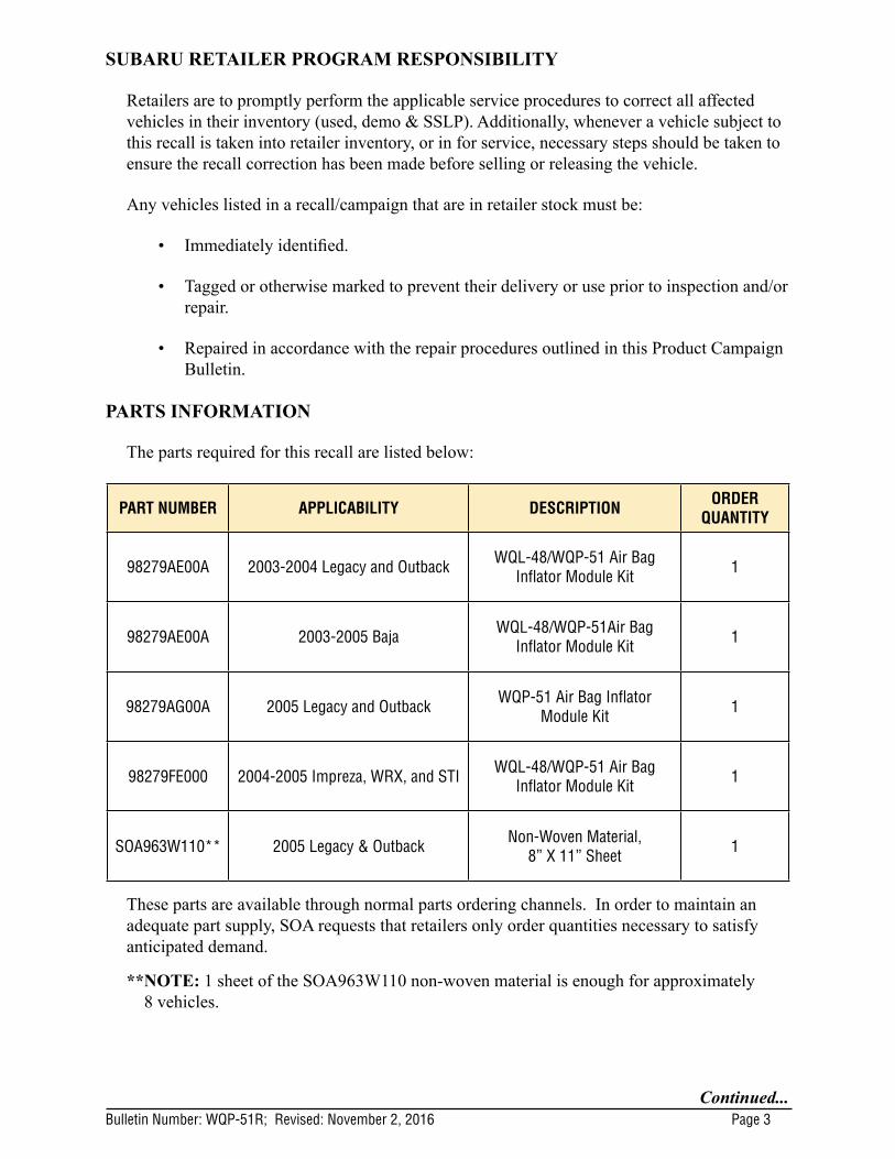
PARTS INFORMATION
The parts required for this recall are listed below:
PART NUMBER APPLICABILITY DESCRIPTION ORDER QUANTITY
98279AE00A 2003-2004 Legacy and Outback WQL-48/WQP-51 Air Bag Inflator Module Kit 1
98279AE00A 2003-2005 Baja WQL-48/WQP-51Air Bag Inflator Module Kit 1
98279AG00A 2005 Legacy and Outback WQP-51 Air Bag Inflator Module Kit 1
98279FE000 2004-2005 Impreza, WRX, and STI WQL-48/WQP-51 Air Bag Inflator Module Kit 1
SOA963W110** 2005 Legacy & Outback Non-Woven Material, 8” X 11” Sheet 1
These parts are available through normal parts ordering channels. In order to maintain an adequate part supply, SOA requests that retailers only order quantities necessary to satisfy anticipated demand.
** NOTE: 1 sheet of the SOA963W110 non-woven material is enough for approximately 8 vehicles.
Bulletin Number: WQP-51R; Revised: November 2, 2016 Page 4Continued...
PART RETURN PROCEDURES
• FedEx will no longer handle the return shipments.• A company called Takata XPO will arrange pick up of the inflators and return them
to Takata.• Once a month or upon accumulating 200 kits for return (whichever comes first)
please call Takata XPO at 1-877-650-3476 for pick up. Please see step 6 of the return instructions.
• Starting in September, 2015 the new inflator return instructions for pick up by Stericycle will be included with each new air bag inflator kit. .
• Upon claim approval, Subaru of America, Inc. will generate a Part Return Notice requesting the old and new inflator serial number information only. DO NOT WAIT FOR TAKATA XPO TO PICK UP THE INFLATOR TO SEND THIS INFORMATION TO THE PARTS COLLECTION CENTER (PCC).
IMPORTANT: Each removed air bag inflator must be returned directly to the supplier, Takata USA, in the same box in which the new one was received.The shipping box contains a bar code label, which will be used by Takata USA to document the replacement of the old inflator with the new inflator. Therefore, it is very important that the removed inflator be returned in the exact same box that contained the newly-installed inflator for that vehicle. If the original box cannot be re-used, please refer to the shipping instructions under “Requesting a new box/ shipping labels.”
• IMPORTANT: When affixing the shipping label to the shipping box do not obstruct the bar code label.
• A completed SOA Warranty Parts Tag (MSA5W402A) must be attached to the returned inflator. The tag must contain the following information: claim number, repair date, full 17-digit VIN, and mileage.
SOA PART RETURN NOTICE• Upon claim approval, Subaru of America, Inc. will generate a Part Return Notice
requesting information only.
• To ensure proper claim credit, the old and new inflator serial numbers must be recorded on the Part Return Notice and sent to SOA Part Collection Center (PCC) as instructed on the return notice.
• The completed Part Return Notice should then be sent using the YRC web portal and utilizing the “Ship Small Parcel” link which will direct the user to the appropriate UPS web page application to complete the shipment. Please keep the UPS tracking number for your records.
• DO NOT WAIT FOR TAKATA XPO TO PICK UP THE PART TO SEND THIS INFORMATION TO THE PCC.
Under no circumstances should the air bag inflator be sent to Subaru of America, Inc.
Please read the ‘Inflator Returns’ instructions included as ‘Appendix A’ of this bulletin carefully, as the return procedure has changed.
• If you continue to receive inventory of inflators with the original FedEx documentation, please follow the instructions in step 4b. of the new ‘Inflator Returns’ instructions. DO NOT CALL FEDEX.

Bulletin Number: WQP-51R; Revised: November 2, 2016 Page 5Continued...
SERVICE PROCEDURE
This Campaign involves the replacement of the inflator portion of the passenger-side front airbag assembly. This procedure will outline removal of the passenger-side airbag assembly and replacement of the inflator component and related wiring harness.
VERY IMPORTANT: Failure to follow these service procedures carefully and correctly may result in an accidental deployment of the inflator and potentially cause serious injury. Please read through and understand these procedures COMPLETELY before beginning repairs. In addition, proper operation of the airbag after reassembly may be compromised if these service procedures are not followed.
Tools Required
DESCRIPTION BRAND OR TYPE QUANTITY
Pliers - 1
Wire Cutters - 1
Needle-Nose Pliers - 1
Torque Wrench Inch-Pound 1
Safety Goggles - 1
Flat-Blade Screwdriver - 1
Scissors - 1
Ratchet1/4” Drive
1
8 mm and 10 mm Socket 1 ea.
Airbag Deployment Fixture J-39401-B 1
NOTE: Although the service procedure is similar for both 2003-04MY Legacy / Outback, 2003-05MY Baja and 2003-05MY Impreza models, there are significant differences in the procedures, especially for 2005MY Legacy / Outback models. For this reason, three different procedures covering all the models listed will be outlined.
CAUTION: Before starting this service procedure, perform a visual inspection of both front airbags looking for any damage or abnormality. Next, turn the ignition switch to the “ON” position and confirm the airbag warning lamp illuminates then extinguishes normally. If it does not or if ANY concern is noted with the airbag system, STOP and report these findings to the customer BEFORE proceeding further. Any concerns identified with the airbag system (when no airbag deployment has occurred), are not related to this campaign and must be ad-dressed separately. Even if the system has a concern, this may not preclude completion of this campaign. If you are unsure about proceeding, document and fully diagnose the concern then contact the SOA Technical Helpline to review your findings. It is in the best interest of the retailer to fully document any concerns found during this preliminary inspection and review with the customer BEFORE proceeding with the campaign service procedure.
Bulletin Number: WQP-51R; Revised: November 2, 2016 Page 6Continued...
• Vehicles that do not contain Genuine Subaru air bags are not eligible for this recall repair. For more information on identifying counterfeit air bags and how to address related customer situations, please refer to STIS for the “Counterfeit Air Bag Information” Dealer Advisory Bulletin dated October 25, 2012 by going to Subarunet>Service>STIS>Online Reference - choose Publication Type: ‘Other/Miscellaneous’ and search keywords: ‘Air Bag’).
• Do not proceed with this repair if your inspection reveals a non-Genuine Subaru air bag module has been installed in the vehicle. Follow the instructions described in the “Counterfeit Air Bag Information” Dealer Advisory Bulletin and contact the SOA Warranty Helpline to close out the recall coverage on the vehicle.
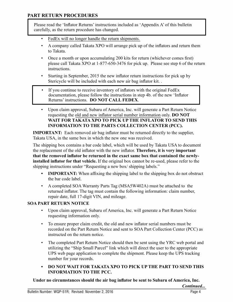
• IMPORTANT: Always examine airbag modules closely before and during removal. Confirm they match the photos of the Genuine Subaru airbag components supplied throughout this bulletin BEFORE proceeding. The photos below are just 2 examples of aftermarket or counterfeit airbag components identified by retailers since the release of this campaign bulletin. These photos are being provided as only 2 examples of what may be a wide variety of non-OEM components.
• If an aftermarket or counterfeit passenger airbag or inflator is identified at any point during the campaign service procedure, STOP IMMEDIATELY. NEVER attempt to remove or otherwise disable any aftermarket or counterfeit device.
• Document the presence of the aftermarket or counterfeit device on the repair order and with photos. Report this information immediately on a Quality Monitoring Report (QMR).
• Once the QMR has been submitted, contact the Subaru Claims Helpline to discuss the details. They will advise you on how to proceed with treatment of the open campaign.
VERY IMPORTANT UPDATE AS OF AUGUST 4, 2016:
Subaru of America, Inc. (Subaru) has been notified by Fuji Heavy Industries (FHI) that some early production 2003 MY Legacy, Outback, and Baja vehicles may have been incorrectly included in the list of vehicles requiring inflator replacement as part of the on-going Takata recalls listed above.
• These early production 2003 MY vehicles (77,000) were equipped with inflators which do not contain ammonium nitrate.
• These inflators which do not contain ammonium nitrate do not require replacement as part of any Subaru airbag recall.
Description of the Remedy
The inspection involves lowering of the glovebox to provide enough access to visually
The shape, holes, and copper-colored stud indicate this
not a Genuine Subaru inflator.
Bulletin Number: WQP-51R; Revised: November 2, 2016 Page 7Continued...
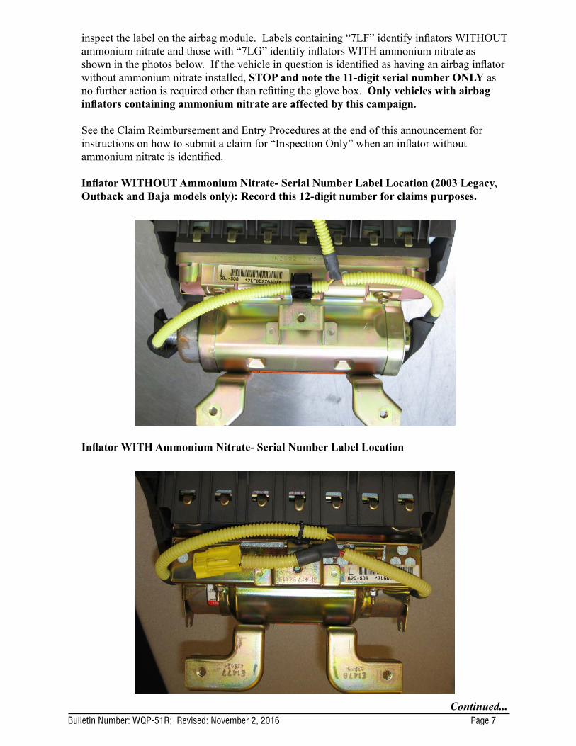
inspect the label on the airbag module. Labels containing “7LF” identify inflators WITHOUT ammonium nitrate and those with “7LG” identify inflators WITH ammonium nitrate as shown in the photos below. If the vehicle in question is identified as having an airbag inflator without ammonium nitrate installed, STOP and note the 11-digit serial number ONLY as no further action is required other than refitting the glove box. Only vehicles with airbag inflators containing ammonium nitrate are affected by this campaign.
See the Claim Reimbursement and Entry Procedures at the end of this announcement for instructions on how to submit a claim for “Inspection Only” when an inflator without ammonium nitrate is identified. Inflator WITHOUT Ammonium Nitrate- Serial Number Label Location (2003 Legacy, Outback and Baja models only): Record this 12-digit number for claims purposes.
Inflator WITH Ammonium Nitrate- Serial Number Label Location

Bulletin Number: WQP-51R; Revised: November 2, 2016 Page 8Continued...
Label Detail
Inflator WITH Ammonium Nitrate“7LG”
Inflator WITHOUT Ammonium Nitrate
“7LF”
Labor Description Labor Operation #
Labor Time
Fail Code
Claim Type
2003MY LEGACY / OUTBACK PASSENGER FRONT AIRBAG INFLATOR INSPECTION ONLY
(Vehicles equipped with inflator WITHOUT ammonium nitrate.)A182-038 0.3 WQP-51 RC
IMPORTANT NOTE: The complete 11-digit airbag module Serial Number MUST be recorded during inspection and entered into the Miscellaneous Detail field as part of the campaign completion / claim entry process.
If you have any questions, please contact the Claims Helpline at 1-866-782-2782.

Bulletin Number: WQP-51R; Revised: November 2, 2016 Page 9Continued...
*SERVICE PROCEDURE FOR 2003-04MY LEGACY, OUTBACK AND 2003-05MY BAJA MODELS*
CAUTION: Refer to the “CAUTION” section in the General Description portion of Airbag System AB in the Body Section of the Service Manual before handling or servicing any airbag module!
STEP 1- PREPARATION:
• Turn the ignition “OFF”.
• Disconnect the Negative (ground) cable from the battery and wait at least 60 seconds before proceeding further.
• Remove the glove box assembly following the procedure in the applicable Service Manual and using the tips below.
The glove box is held in place by 8 screws.
о The 2 upper left and right hand corner screws have a distinctive gold finish and 10mm hex head. It is helpful to leave these 2 screws until last when removing and install first during replacement to support the weight of the assembly.
о It is necessary to remove the knockout plugs (stopper in the Service Manual) to gain access to all the mounting screws.
о It is possible to leave the stoppers in place during servicing by carefully bending in the sides of the glove box until the stoppers are cleared.
• To prevent damage, do not bend them in any further than necessary.
• IMPORTANT: Whenever beginning to remove (or install) the airbag assembly, and periodically while performing the procedure or after stepping away, remove any possible static charge from your body by momentarily touching a clean, bare metal ground point on the vehicle (e.g. the door striker). Remove from your person all electronic devices including cell phones before proceeding.
• Disconnect the airbag module harness connector (A) and release it from the support beam bracket.
Bulletin Number: WQP-51R; Revised: November 2, 2016 Page 10Continued...
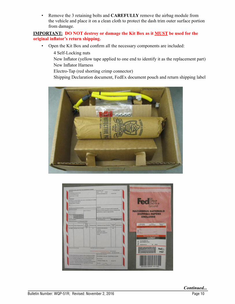
• Remove the 3 retaining bolts and CAREFULLY remove the airbag module from the vehicle and place it on a clean cloth to protect the dash trim outer surface portion from damage.
IMPORTANT: DO NOT destroy or damage the Kit Box as it MUST be used for the original inflator’s return shipping.
• Open the Kit Box and confirm all the necessary components are included: 4 Self-Locking nutsNew Inflator (yellow tape applied to one end to identify it as the replacement part)New Inflator HarnessElectro-Tap (red shorting crimp connector)Shipping Declaration document, FedEx document pouch and return shipping label

Bulletin Number: WQP-51R; Revised: November 2, 2016 Page 11Continued...
• IMPORTANT: The removed airbag module must be mounted to the Airbag Deployment Fixture (part number J-39401-B) as shown in the photo below to better secure it during the inflator and wiring harness component replacement procedures. When mounting the module to the fixture, pay close attention to the harness routing as shown in the photo below. Always perform this work in an area away from others to reduce chances of inadvertent injury should any deployment occur. Take your surroundings into account to avoid possible hazards should inadvertent deployment occur or sources of static or other electricity that could potentially induce such a deployment.
STEP 2- Remove the harness clip from the retainer bracket by rotating the harness / clip 90 degrees then releasing it from the bracket with needle-nose pliers.
STEP 3- CAREFULLY cut the yellow harness cover (approximately 1 1/2 inches) enough to expose the 2 yellow wires inside and provide enough room to install the Electro-Tap (shorting) connector using a scissor or wire cutter (no knives or razors). TAKE YOUR TIME AND BE CAREFUL TO NOT CUT THE 2 YELLOW WIRES!

Bulletin Number: WQP-51R; Revised: November 2, 2016 Page 12Continued...
STEP 4- Short the 2 yellow wires together by installing the Electro-Tap connector. The connector creates a short circuit which acts as a safeguard to prevent against static discharge that may deploy the removed inflator. The tab portion of the Electro-Tap connector MUST be cut off prior to use to insure a good short-circuit is made as shown in the illustration below. Follow the sequence below for installing the Electro-Tap connector. Use pliers to squeeze closed the two sections of the connector together, one section at a time.
STEP 5- Once the Electro-Tap connector is fully crimped in place, cut the 2 yellow wires on the body harness connector side of the Electro-Tap connector.
This tab MUST be cut off
Insert 1 wire in the Electro-Tap
Fold
1 2 3
4
Crimp closed with pliers
Place the other wire in the
Electro-Tap, fold then crimp
closed with pliers
5
CUT

Bulletin Number: WQP-51R; Revised: November 2, 2016 Page 13Continued...
STEP 6- Remove the two 8mm self-locking nuts securing the stopper plate. Loosen but do not remove the other two nuts on the mounting bracket as leaving them in place will help keep the airbag assembly together.
NEVER ATTEMPT TO REMOVE THE HARNESS CONNECTORS FROM THE INFLATOR!
STEP 7- With the stopper plate removed and the other 2 self-locking nuts loosened, unseat the inflator off the mounting bracket end plate then rotate it slightly CLOCKWISE to make it easier to remove as shown below. Slide the original inflator out of the mounting bracket while feeding the cut off portion of the wiring harness through the “D-Shaped” hole in the end plate. NEVER ATTEMPT TO REMOVE THE HARNESS CONNECTORS FROM THE INFLATOR! Place the removed original air bag inflator in the “cradle” of the Kit Box insert.
Stopper Plate

Bulletin Number: WQP-51R; Revised: November 2, 2016 Page 14Continued...
STEP 8- VERY IMPORTANT: Record the FedEx Shipper Receipt Number (located at the top of the return shipping label included with the new inflator) and the 11-digit alpha-numeric serial number for both the new and the removed inflators on the hard copy of the Repair Order. This information will be required for completion of the Part Return Notice which will be forwarded by the retailer to the PCC.
STEP 9- Install the new inflator into the mounting bracket so the yellow taped end aligns with the removed stopper plate. Make sure the “D-shaped” portion of the inflator harness connector boss aligns with the “D-shaped” portion of the hole in the end of the mounting bracket as shown below. When properly installed, the end of the inflator will be seated tight against the mounting bracket. Do not peel the white harness connection dust cover at this time.
STEP 10- As shown below, install but do not fully tighten 2 of the NEW self-locking nuts while holding the stopper plate tight against the inflator. Remove the nuts still installed on the mounting bracket and replace them with 2 NEW self-locking nuts. Once all 4 NEW nuts are in place, torque to 31 - 38 inch pounds in the sequence shown below. Use a marker to mark the nuts after torquing to indicate they have been fully tightened.
3
2
1
4
Inflator properly seated against
mounting bracket (NO GAP)
Bulletin Number: WQP-51R; Revised: November 2, 2016 Page 15Continued...
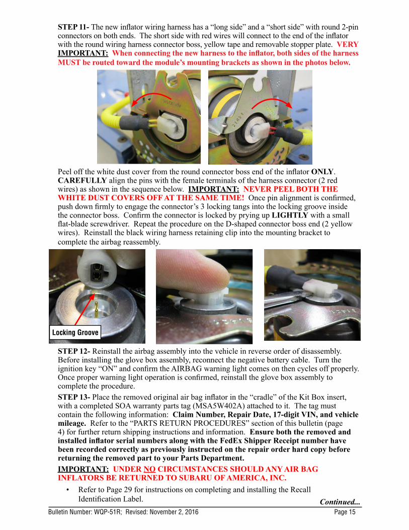
STEP 11- The new inflator wiring harness has a “long side” and a “short side” with round 2-pin connectors on both ends. The short side with red wires will connect to the end of the inflator with the round wiring harness connector boss, yellow tape and removable stopper plate. VERY IMPORTANT: When connecting the new harness to the inflator, both sides of the harness MUST be routed toward the module’s mounting brackets as shown in the photos below.
Peel off the white dust cover from the round connector boss end of the inflator ONLY. CAREFULLY align the pins with the female terminals of the harness connector (2 red wires) as shown in the sequence below. IMPORTANT: NEVER PEEL BOTH THE WHITE DUST COVERS OFF AT THE SAME TIME! Once pin alignment is confirmed, push down firmly to engage the connector’s 3 locking tangs into the locking groove inside the connector boss. Confirm the connector is locked by prying up LIGHTLY with a small flat-blade screwdriver. Repeat the procedure on the D-shaped connector boss end (2 yellow wires). Reinstall the black wiring harness retaining clip into the mounting bracket to complete the airbag reassembly.
STEP 12- Reinstall the airbag assembly into the vehicle in reverse order of disassembly. Before installing the glove box assembly, reconnect the negative battery cable. Turn the ignition key “ON” and confirm the AIRBAG warning light comes on then cycles off properly. Once proper warning light operation is confirmed, reinstall the glove box assembly to complete the procedure.STEP 13- Place the removed original air bag inflator in the “cradle” of the Kit Box insert, with a completed SOA warranty parts tag (MSA5W402A) attached to it. The tag must contain the following information: Claim Number, Repair Date, 17-digit VIN, and vehicle mileage. Refer to the “PARTS RETURN PROCEDURES” section of this bulletin (page 4) for further return shipping instructions and information. Ensure both the removed and installed inflator serial numbers along with the FedEx Shipper Receipt number have been recorded correctly as previously instructed on the repair order hard copy before returning the removed part to your Parts Department. IMPORTANT: UNDER NO CIRCUMSTANCES SHOULD ANY AIR BAG INFLATORS BE RETURNED TO SUBARU OF AMERICA, INC.
• Refer to Page 29 for instructions on completing and installing the Recall Identification Label.
Locking Groove

Bulletin Number: WQP-51R; Revised: November 2, 2016 Page 16Continued...
*SERVICE PROCEDURE FOR 2004-05MY IMPREZA, WRX and STI MODELS*CAUTION: Refer to the “CAUTION” section in the General Description portion of Airbag System AB in the Body Section of the Service Manual before handling or servicing the airbag module!STEP 1- PREPARATION:
• Turn the ignition “OFF”.• Disconnect the Negative (ground) cable from the battery and wait at least 60 seconds
before proceeding further.• Remove the glove box assembly following the procedure in the applicable Service
Manual.IMPORTANT: Whenever beginning to remove (or install) the airbag assembly, and periodically while performing the procedure or after stepping away, remove any possible static charge from your body by momentarily touching a clean, bare metal ground point on the vehicle (e.g. the door striker). Remove from your person all electronic devices including cellphones before proceeding.
• Disconnect the airbag module harness connector from the support beam bracket.
• Remove the 3 retaining bolts and CAREFULLY remove the airbag module from the vehicle and place it on a clean cloth to protect the dash trim surface portion from damage.
NOTE: There may be a Security Module secured with the lower airbag module mounting bolt on some models.
IMPORTANT: DO NOT destroy or damage the kit box as it MUST be used for the original inflator’s return shipping.
• Open the Kit Box and confirm all the necessary components are included: 4 Self-Locking nutsNew Inflator (yellow tape applied to one end to identify it as the replacement part)New Inflator HarnessElectro-Tap (red shorting crimp connector)1 ½” X 2 ¼” piece of self-adhesive Sponge TapeShipping Declaration document, FedEx document pouch and return shipping label

Bulletin Number: WQP-51R; Revised: November 2, 2016 Page 17Continued...
• IMPORTANT: The removed airbag module must be mounted to the Airbag Deployment Fixture (part number J-39401-B) as shown in the photo below to better secure it during the inflator and wiring harness component replacement procedures. Always perform this work in an area away from others to reduce chances of inadvertent injury should any deployment occur. Take your surroundings into account to avoid possible hazards should inadvertent deployment occur or sources of static or other electricity that could potentially induce such a deployment.
STEP 2- Peel the Sponge Tape and remove the harness clip from the retainer bracket by pushing the tangs inward with a flat-blade screwdriver as shown below. Always remove any Sponge Tape adhesive residue from the airbag mounting bracket using mild solvent on a clean shop cloth. CAUTION: Never use any silicone-based products for this purpose.
STEP 3- CAREFULLY cut the yellow harness cover enough (approximately 2 inches) to expose the 2 red or yellow wires inside and provide enough room to install the Electro-Tap (shorting) connector using a wire cutter or scissor (no knives or razors). TAKE YOUR TIME AND BE CAREFUL TO NOT CUT THE 2 WIRES!
Red Wires Yellow Wires

Bulletin Number: WQP-51R; Revised: November 2, 2016 Page 18Continued...
STEP 4- Short the 2 wires together by installing the Electro-Tap connector. The connector creates a short circuit which acts as a safeguard to prevent against static discharge that may deploy the removed inflator. The tab portion of the Electro-Tap connector MUST be cut off prior to use to insure a good short-circuit is made as shown in the illustration below. Follow the sequence below for installing the Electro-Tap connector. Use pliers to squeeze closed the two sections of the connector together, one section at a time.
STEP 5- Once the Electro-Tap connector is fully crimped in place, cut the 2 wires on the body harness connector side of the Electro-Tap connector.
STEP 6- Remove the two 8mm self-locking nuts securing the stopper plate. Loosen but do not remove the other two nuts on the mounting bracket as leaving them in place will help keep the airbag assembly together.
CUT
Remove
This tab MUST be cut off
Insert 1 wire in the Electro-Tap
Fold
2 3
4
Crimp closed with pliers
Place the other wire in the
Electro-Tap, fold then crimp
closed with pliers
5

Bulletin Number: WQP-51R; Revised: November 2, 2016 Page 19Continued...
STEP 7- With the stopper plate removed and the other 2 self-locking nuts loosened, unseat the inflator off the mounting bracket end plate then rotate it slightly CLOCKWISE to make it easier to remove as shown in the photo to the right. Slide the inflator out of its mounting while feeding the cut off portion of the wiring harness through the “D-Shaped” hole in the end of the mounting bracket. NEVER ATTEMPT TO REMOVE THE HARNESS FROM THE INFLATOR! Place the removed original air bag inflator in the “cradle” of the Kit Box insert.
STEP 8- VERY IMPORTANT: Record the FedEx Shipper Receipt Number (located at the top of the return shipping label included with the new inflator) and the 11-digit alpha-numeric serial number for both the new and the removed inflators on the hard copy of the Repair Order. This information will be required for completion of the Part Return Notice which will be forwarded by the retailer to the PCC. The new serial number is also a requirement for claim entry.
STEP 9- Install the new inflator into the mounting bracket with the harness connector end going in first toward the mounting bracket. Make sure the “D-shaped” portion of the inflator harness connector boss aligns with the “D-shaped” portion of the hole in the end of the mounting bracket as shown below. When properly installed, the end of the inflator will be seated tight against the mounting bracket. Do not peel the white harness connection dust cover at this time.
Inflator properly seated against
mounting bracket (NO GAP)

Bulletin Number: WQP-51R; Revised: November 2, 2016 Page 20Continued...
STEP 10- As shown below, install but do not fully tighten 2 of the NEW self-locking nuts while holding the stopper plate tight against the inflator. Remove the nuts still installed on the mounting bracket and replace them with 2 NEW self-locking nuts. Once all 4 NEW nuts are in place, torque to 31 - 38 inch pounds in the sequence shown below. Use a marker to mark the nuts after torquing indicating they have been fully tightened.
STEP 11- VERY IMPORTANT: When connecting the new harness to the inflator, the harness MUST be routed toward the module’s mounting brackets as shown in the photo below. Peel off the white dust cover and CAREFULLY align the 2 inflator pins with the female terminals of the harness connector as shown in the sequence below. Once pin alignment is confirmed, push down firmly to engage the connector’s 2 locking tangs into the locking groove of the connector boss. Confirm the connector is fully locked by prying up LIGHTLY with a small flat-blade screwdriver.
STEP 12- Reinstall the wiring harness retaining clip into its position on the mounting bracket.
Locking Groove

Bulletin Number: WQP-51R; Revised: November 2, 2016 Page 21Continued...
STEP 13- Peel the adhesive backing and install the new Sponge Tape onto the yellow harness tube first then adhere it to the airbag mounting bracket as shown in the illustrations below.
STEP 14- Reinstall the airbag assembly into the vehicle in reverse order of disassembly. NOTE: If the accessory security module is installed to one of the airbag module mounting bolts, torque that specific bolt to 7.5 +/-1ft. lb. rather than the normal 5.4 ft. lb. specified in the Service Manual. Before installing the glove box assembly, reconnect the negative battery cable. Turn the ignition key “ON” and confirm the AIRBAG warning light comes on then cycles off properly. Once proper warning light operation is confirmed, reinstall the glove box assembly while making sure the cord loop for the opening dampener (if equipped) stays connected to complete the procedure.STEP 15- Place the removed air bag inflator in the “cradle” of the Kit Box insert, with a completed SOA warranty parts tag (MSA5W402A) attached to it. The tag must contain the following information: Claim Number, Repair Date, 17-digit VIN, and vehicle mileage. Refer to the “PARTS RETURN PROCEDURES” section of this bulletin (page 4) for further return shipping instructions and information.IMPORTANT: UNDER NO CIRCUMSTANCES SHOULD ANY AIR BAG INFLATORS BE RETURNED TO SUBARU OF AMERICA, INC.
• Refer to Page 29 for instructions on completing and installing the Recall Identification Label.
IMPORTANT: The Sponge tape must be installed more than half-way around the yellow harness tube.
Harness Sponge Tape

Bulletin Number: WQP-51R; Revised: November 2, 2016 Page 22Continued...
*SERVICE PROCEDURE FOR 2005MY LEGACY / OUTBACK MODELS*
CAUTION: Refer to the “CAUTION” section in the General Description portion of Airbag System AB in the Body Section of the Service Manual before handling or servicing any airbag module!
STEP 1- PREPARATION:
• Turn the ignition “OFF”.• Disconnect the Negative (ground) cable from the battery and wait at least 60 seconds
before proceeding further.• Follow the procedures in the applicable Service Manual for removing the instrument
panel assembly as required to access the passenger side airbag module.• Disconnect the wiring harness and remove the airbag module.• Secure the airbag module to the Airbag Deployment Fixture (part number J-39401-B)
as shown in the photo below.
IMPORTANT: Whenever beginning to remove (or install) the airbag assembly, and periodically while performing the procedure or after stepping away, remove any possible static charge from your body by momentarily touching a clean, bare metal ground point on the vehicle (e.g. the door striker). Remove from your person all electronic devices including cell phones before proceeding.
IMPORTANT: DO NOT destroy or damage the Kit Box as it MUST be used for the original inflator’s return shipping.
Open the Kit Box and confirm all the necessary components are included
• 4 Self-Locking nuts• New Inflator (yellow tape applied to one end to identify it as the replacement part)• New Inflator Harness• Electro-Tap (red shorting crimp connector)• New Stopper Plate with D-Shaped hole• Self-Adhesive Foam Protector • Shipping Declaration document, FedEx document pouch and return shipping label

Bulletin Number: WQP-51R; Revised: November 2, 2016 Page 23Continued...
To access the passenger’s airbag module, the complete instrument panel assembly must be removed. Follow the procedures in the applicable Service Manual for removing the instrument panel assembly in addition to the necessary related interior trim components.
NOTE: When removing the “A” pillar trim, be VERY CAREFUL not to damage the upper metal retaining clip. The clip is located just below where the trim panel meets the head liner. If the metal retaining clip becomes damaged or separated from the trim panel, the trim panel MUST be replaced as the clip is not available separately. Use a plastic trim tool to push and release the upper portion of the metal clip from the body. Be careful to not pull the trim panel open any further than necessary to gain access for releasing the clip. There is a plastic retaining clip in the lower portion of the trim panel which will release easily once the upper retaining clip is loose. At reassembly and using a plastic trim tool, make sure the inner lip of the door weatherstrip overlaps the outer fabric edge of the trim panel to help secure it.
Insert Trim Tool
Lip of Door Weatherstrip
Overlaps Fabric Edge of Trim Panel
Push to Release
1 2
3 4

Bulletin Number: WQP-51R; Revised: November 2, 2016 Page 24Continued...
Once the instrument panel assembly has been removed from the vehicle, CAREFULLY separate the airbag module from it.
IMPORTANT: The removed airbag module must be mounted to the Airbag Deployment Fixture (part number J-39401-B) as shown in the photo below to better secure it during the inflator and wiring harness component replacement procedures. When mounting the module to the fixture, pay close attention to the harness routing as shown in the photo below. Always perform this work in an area away from others to reduce chances of inadvertent injury should any deployment occur. Take your surroundings into account to avoid possible hazards should inadvertent deployment occur or sources of static or other electricity that could potentially induce such a deployment.
STEP 2- Remove both sides of the harness from the retainer bracket holders.
Bulletin Number: WQP-51R; Revised: November 2, 2016 Page 25Continued...
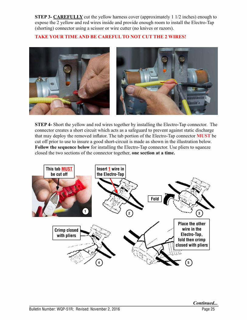
STEP 3- CAREFULLY cut the yellow harness cover (approximately 1 1/2 inches) enough to expose the 2 yellow and red wires inside and provide enough room to install the Electro-Tap (shorting) connector using a scissor or wire cutter (no knives or razors).
TAKE YOUR TIME AND BE CAREFUL TO NOT CUT THE 2 WIRES!
STEP 4- Short the yellow and red wires together by installing the Electro-Tap connector. The connector creates a short circuit which acts as a safeguard to prevent against static discharge that may deploy the removed inflator. The tab portion of the Electro-Tap connector MUST be cut off prior to use to insure a good short-circuit is made as shown in the illustration below. Follow the sequence below for installing the Electro-Tap connector. Use pliers to squeeze closed the two sections of the connector together, one section at a time.
This tab MUST be cut off
Insert 1 wire in the Electro-Tap
Fold
1 2 3
4
Crimp closed with pliers
Place the other wire in the
Electro-Tap, fold then crimp
closed with pliers
5

Bulletin Number: WQP-51R; Revised: November 2, 2016 Page 26Continued...
STEP 5- Once the Electro-Tap connector is fully crimped in place, cut the yellow and red wires on the body harness connector side of the Electro-Tap connector as shown below.
STEP 6- Loosen but do not remove the two 10mm self-locking nuts securing the stopper plate securing the end of the inflator with the blue and white wires as leaving them in place will help keep the airbag assembly together. Remove the two nuts and the stopper plate on the on the opposite end of the inflator mounting bracket and discard them. NEVER ATTEMPT TO REMOVE THE HARNESS CONNECTORS FROM THE INFLATOR! With the stopper plate removed and the other 2 self-locking nuts loosened, slide the original inflator out of the mounting bracket while feeding the cut off portion of the wiring harness under the remaining stopper plate. Place the removed original air bag inflator in the “cradle” of the Kit Box insert.

Bulletin Number: WQP-51R; Revised: November 2, 2016 Page 27Continued...
STEP 7 - VERY IMPORTANT: Record the FedEx Shipper Receipt Number (located at the top of the return shipping label included with the new inflator) and the 11-digit alpha-numeric serial number for both the new and the removed inflators on the hard copy of the Repair Order. This information will be required for completion of the Part Return Notice which will be forwarded by the retailer to the PCC.
STEP 8- Install the new inflator into the mounting bracket so the yellow taped end aligns with the stopper plate still installed on the mounting bracket. Make sure the “D-shaped” portion of the inflator harness connector boss aligns with the “D-shaped” portion of the hole in the new replacement stopper plate as shown below. Do not peel the white harness connection dust cover at this time. Use 2 NEW self-locking nuts to secure the new stopper plate but do not fully tighten them. Remove the other 2 nuts securing the other stopper plate on the mounting bracket and replace them with 2 NEW self-locking nuts. When properly installed, both ends of the inflator will be seated tight against both stopper plates with no gaps.
Properly Aligned
3
2
1
4
No Gap No Gap

Bulletin Number: WQP-51R; Revised: November 2, 2016 Page 28Continued...
STEP 9- Once all 4 NEW nuts are in place, torque to 31 - 38 inch pounds in the sequence shown above. Use a marker to mark the nuts after torquing to indicate they have been fully tightened.
STEP 10- Install the black foam self-adhesive protector onto the D-Shaped stopper and mounting bracket positioned as shown in the photo sequence below. Once adhered in place on the new stopper plate, fold over the excess as shown. Always make sure the placement area for the protector is free of any grease or dirt before application.
3
21
4

Bulletin Number: WQP-51R; Revised: November 2, 2016 Page 29Continued...
STEP 11- The new inflator wiring harness has 2 “sides” with round 2-pin connectors on both ends. The side with the yellow corrugated tube and red / yellow wires will connect to the end of the inflator with the D-Shaped wiring harness connector boss, new stopper plate and foam protector as shown below. Peel off the white dust cover from the D-Shaped end of the inflator ONLY. IMPORTANT: NEVER PEEL BOTH THE WHITE DUST COVERS OFF AT THE SAME TIME! CAREFULLY align the pins with the female terminals of the harness connector (red / yellow wires) as shown in the photos below. Once pin alignment is confirmed, push down firmly to engage the connector’s 3 locking tangs into the locking groove inside the connector boss. Confirm the connector is locked by prying up LIGHTLY with a small flat-blade screwdriver. Repeat the procedure on the opposite end with the blue / white wires.
VERY IMPORTANT: When connecting the new harness to the inflator, both sides of the harness MUST be routed toward the module’s mounting brackets as shown in the photos below.
Locking Groove

Bulletin Number: WQP-51R; Revised: November 2, 2016 Page 30Continued...
STEP 12- Refit the ends of the harness corrugated tubes to the retaining grooves of the mounting bracket as shown to complete the airbag module reassembly.
STEP 13- CAREFULLY reinstall the airbag module assembly into the instrument panel as shown below.
STEP 14- To eliminate a possible source of a rattling sound from the dash, wrap the 2 hooks and locator pin with non-woven material, p.n. SOA963W110 (or an equivalent self-adhesive foam) as shown below.
REMINDER: 1 sheet of the SOA963W110 non-woven material is enough for approximately 8 vehicles.
Hook HookLocator Pin
Bulletin Number: WQP-51R; Revised: November 2, 2016 Page 31Continued...
STEP 15- Reinstall the instrument panel assembly into the vehicle in reverse order of disassembly. Once the negative battery cable has been reconnected, turn the ignition key “ON” and confirm the AIRBAG warning light comes on then cycles off properly. Once proper warning light operation is confirmed, reinstall the remaining components to complete the procedure.
STEP 16- Place the removed original air bag inflator in the “cradle” of the Kit Box insert, with a completed SOA warranty parts tag (MSA5W402A) attached to it. The tag must contain the following information: Claim Number, Repair Date, 17-digit VIN, and vehicle mileage. Refer to the “PART RETURN PROCEDURES” section of this bulletin (page 4) for further return shipping instructions and information. Ensure both the removed and installed inflator serial numbers along with the FedEx Shipper Receipt number have been recorded correctly as previously instructed on the repair order hard copy before returning the removed part to your Parts Department.
IMPORTANT: UNDER NO CIRCUMSTANCES SHOULD ANY AIR BAG INFLATORS BE RETURNED TO SUBARU OF AMERICA, INC.
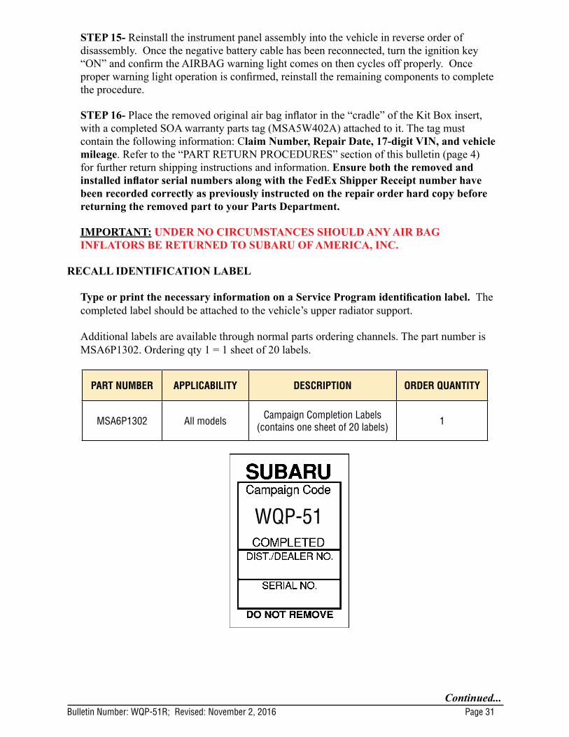
RECALL IDENTIFICATION LABEL
Type or print the necessary information on a Service Program identification label. The completed label should be attached to the vehicle’s upper radiator support.
Additional labels are available through normal parts ordering channels. The part number is MSA6P1302. Ordering qty 1 = 1 sheet of 20 labels.
PART NUMBER APPLICABILITY DESCRIPTION ORDER QUANTITY
MSA6P1302 All models Campaign Completion Labels (contains one sheet of 20 labels) 1
WQP-51

Bulletin Number: WQP-51R; Revised: November 2, 2016 Page 32Continued...
CLAIM REIMBURSEMENT AND ENTRY PROCEDURESCredit to perform this recall will be based on the submission of properly completed repair order information. Retailers may submit claims through ‘Vehicle Claim Entry’ on Subarunet.com.Listed below is claim entry information:
CLAIM TYPE
CAMPAIGN CODE APPLICABILITY LABOR DESCRIPTION LABOR
TIME
RC WQP-51
2003-2004 Legacy and
Outback
2003-2005 Baja
2004-2005 Impreza, WRX,
and STI
A182-031 Front Passenger Air Bag Inflator Replacement 0.8
RC WQP-51 2005 Legacy and Outback A182-031 Front Passenger Air Bag Inflator
Replacement 1.8
PART NUMBER APPLICABILITY DESCRIPTION QUANTITY
98279AE00A 2003-2004 Legacy and Outback
WQL-48/WQP-51 Air Bag Inflator Module Kit 1
98279AE00A 2003-2005 Baja WQL-48/WQP-51 Air Bag Inflator Module Kit 1
98279AG00A 2005 Legacy and Outback WQP-51 Air Bag Inflator Module Kit 1
98279FE0002004-2005
Impreza, WRX, and STI
WQL-48/WQP-51 Air Bag Inflator Module Kit 1
SOA635079** 2005 Legacy & Outback
Non-Woven Material (order part number SOA963W110) 1
** NOTE: For claim entry, use part # SOA635079 for the non-woven material. This part # is non-orderable and used for claim purposes only.
Miscellaneous Detail Enter the serial number of the NEW air bag inflator installed in the “Misc. Details” field.

Bulletin Number: WQP-51R; Revised: November 2, 2016 Page 33Continued...
OWNER NOTIFICATION LETTER
Dear Subaru Owner:
This notice is sent to you in accordance with the National Traffic and Motor Vehicle Safety Act.
Subaru of America, Inc. has decided that a defect which relates to motor vehicle safety exists in certain 2003-2005 model year Subaru Legacy and Outback vehicles, 2003-2005 model year Subaru Baja vehicles, and 2004-2005 model year Subaru Impreza (including WRX/STI) vehicles.
You received this notice because our records indicate that you currently own one of these vehicles.
REASON FOR THE RECALL
The National Highway Traffic Administration (NHTSA) is investigating whether exposure to high absolute humidity may, upon air bag deployment, lead to a rupture of air bag inflators produced by TK Holdings, Inc. (Takata). In cooperation with that investigation, Subaru is conducting this regional recall to replace Takata front passenger air bag inflators in certain vehicles with current or previous registration in the following areas of high absolute humidity:
REMEDY
Subaru will replace the inflator for your front passenger air bag at no cost to you.
Subaru Recall Campaign WQP-51NHTSA Recall No. 14V-763January 2015
IMPORTANT SAFETY RECALLThis notice applies to the VIN identified in the address section printed below.
• The following States and U.S. Territories:o Florida o Hawaii o Puerto Rico o U.S. Virgin Islands o Guam o Saipan o American Samoa
• The counties of Georgia which are adjacent to Florida
• The coastal areas of:
o Alabama o Louisiana o Mississippi o Texas
SAFETY HAZARDIn the event of a crash necessitating deployment of the front passenger air bag, the inflator could rupture with metal fragments striking and potentially seriously injuring the vehicle occupants.
WHAT YOU SHOULD DOYou should immediately contact your Subaru retailer (dealer) for an appointment to have the front passenger air bag inflator replaced with a new one.
Until this repair is performed, do not allow passengers to ride in the front passenger seat.

Bulletin Number: WQP-51R; Revised: November 2, 2016 Page 34Continued...
Although we have not experienced a parts shortage, we will cover a loaner vehicle if your retailer does not have the part in stock to repair your vehicle under this recall. If you are uncomfortable driving the vehicle to your Subaru retailer, please contact your Subaru retailer who will arrange for vehicle pick up.
HOW LONG WILL THE AIR BAG INFLATOR REPLACEMENT TAKE?
The time to replace the front passenger air bag inflator is approximately one hour and 45 minutes for the affected 2005 model year Legacy and Outback vehicles, and approximately 40 minutes for all of the other vehicles affected by this recall. It may be necessary to leave your vehicle for a longer period of time on the day of your scheduled appointment to allow your Subaru retailer flexibility in scheduling. Please present this letter to your Subaru retailer at the time this repair procedure is performed.
CHANGED YOUR ADDRESS OR SOLD YOUR SUBARU?
If you have moved or sold your vehicle, please complete the enclosed prepaid postcard and mail it to us. Or if you prefer to update this information online, please go to www.subaru.com, select ‘Customer Support,’ then select ‘Address Update’ or ‘Ownership Update’ from the drop down menu.
IF YOU NEED FURTHER ASSISTANCE:
To locate the nearest Subaru retailer you can access our website at www.subaru.com and select ‘Find a Retailer.’
For additional information and the most Frequently Asked Questions, please go to:
• http://www.wqp51.service-campaign.com
If you need additional assistance, please contact us directly:
• By e-mail: Go to www.subaru.com and select ‘Customer Support’
• By telephone: 1-800-SUBARU3 (1-800-782-2783) Monday through Thursday between 7:30 a.m. and 8:00 p.m. ET Friday between 10:30 a.m. and 5:00 p.m. ET Saturday between 9:00 a.m. and 3:30 p.m. ET
• By U.S. Postal mail: Write us at Subaru of America, Inc., Attn: Customer-Retailer Services Department, P.O. Box 6000, Cherry Hill, NJ 08034-6000
Please contact us immediately if the Subaru retailer fails or is unable to make the necessary repairs free of charge.
You may also contact the Administrator, National Highway Traffic Safety Administration, 1200 New Jersey Ave. SE, West Building, Washington, DC 20590 or call the toll free Auto Safety Hotline at 1-888-327-4236 (TTY: 1-800-424-9153) or go to http://www.safercar.gov if you believe the Subaru retailer has failed or is unable to remedy your vehicle without charge within a reasonable amount of time.
Your continued satisfaction with your Subaru is important to us. Please understand that we have taken this action in the interest of your safety and your vehicle’s proper operation. We sincerely apologize for any inconvenience this matter may cause and urge you to schedule an appointment as soon as possible to have this repair performed.
Sincerely, Subaru of America, Inc.
Notice to Lessors: Under Federal law the lessor of a vehicle who receives this letter must provide a copy of it to the vehicle lessee(s) within 10 business days from receipt. The lessor must also keep a record of the lessee(s) to whom this letter is sent, the date sent, and the applicable vehicle identification number (VIN). (For the purposes of this section, a lessor means a person or entity that in the last twelve months prior to the date of this notification has been the owner, as referenced on the vehicle’s title, of any five or more leased vehicles. A leased vehicle is a vehicle leased to another person for a term of at least four months.)
A subsidiary of Fuji Heavy Industries Ltd.

Bulletin Number: WQP-51R; Revised: November 2, 2016 Page 35Continued...
SECOND OWNER NOTIFICATION LETTER
Subaru Recall Campaign WQP-51NHTSA Recall No. 14V-763November 2016 – Second Notice
IMPORTANT SAFETY RECALLThis notice applies to the VIN identified in the address section printed below.
Dear Subaru Owner:
This notice is sent to you in accordance with the National Traffic and Motor Vehicle Safety Act.
SUBARU OF AMERICA, INC. has decided that a defect, which relates to motor vehicle safety, exists in certain 2003-2004 model year Subaru Legacy and Outback vehicles and certain 2003-2005 model year Subaru Baja vehicles, equipped with a non-desiccated Takata-sourced passenger side frontal air bag containing the propellant Phase Stabilized Ammonium Nitrate.
You received this notice because our records indicate that you currently own one of these vehicles.
DESCRIPTION OF THE SAFETY DEFECT AND SAFETY HAZARD
The affected vehicles are equipped with a Takata-sourced passenger side frontal air bag that may be susceptible to moisture intrusion. Over time, that could cause the inflator to rupture when the passenger’s frontal air bag deploys in a crash. If the inflator ruptures, metal fragments could strike vehicle occupants, potentially resulting in serious injury or death.
WHAT YOU SHOULD DOYou should immediately contact your Subaru retailer (dealer) for an appointment to have the front passenger air bag inflator replaced with a new one.
Until this repair is performed, do not allow passengers to ride in the front passenger seat.
HOW LONG WILL THE AIR BAG INFLATOR REPLACEMENT TAKE?
The time to replace the front passenger air bag inflator is approximately 45 minutes. It may be necessary to leave your vehicle for a longer period of time on the day of your scheduled appointment. Please present this letter to your Subaru retailer at the time this repair procedure is performed.
CHANGED YOUR ADDRESS OR SOLD YOUR SUBARU?
If you have moved or sold your vehicle, please complete the enclosed prepaid postcard and mail it to us. Or if you prefer to update this information online, please go to www.subaru.com, select ‘Customer Support,’ then select ‘Address Update’ or ‘Ownership Update’ from the drop down menu.

Bulletin Number: WQP-51R; Revised: November 2, 2016 Page 36Continued...
Notice to Lessors: Under Federal law the lessor of a vehicle who receives this letter must provide a copy of it to the vehicle lessee(s) within 10 business days from receipt. The lessor must also keep a record of the lessee(s) to whom this letter is sent, the date sent, and the applicable vehicle identification number (VIN). (For the purposes of this section, a lessor means a person or entity that in the last twelve months prior to the date of this notification has been the owner, as referenced on the vehicle’s title, of any five or more leased vehicles. A leased vehicle is a vehicle leased to another person for a term of at least four months.)
A subsidiary of Fuji Heavy Industries Ltd.
IF YOU NEED FURTHER ASSISTANCE:
To locate the nearest Subaru retailer, you can access our website at www.subaru.com and select ‘Find a Retailer.’
For additional information about future parts availability and the most Frequently Asked Questions, please go to:
• http://www.wqp51.service-campaign.com
If you need additional assistance, please contact us directly:
• By e-mail: Go to www.subaru.com and select ‘Customer Support’
• By telephone: 1-800-SUBARU3 (1-800-782-2783) Monday through Thursday between 7:30 a.m. and 8:00 p.m. ET Friday between 10:30 a.m. and 5:00 p.m. ET Saturday between 9:00 a.m. and 3:30 p.m. ET
• By U.S. Postal mail: Write us at Subaru of America, Inc., Attn: Customer-Retailer Services Department, P.O. Box 6000, Cherry Hill, NJ 08034-6000
Please contact us immediately if the Subaru retailer fails or is unable to make the necessary repairs free of charge.
You may also contact the Administrator, National Highway Traffic Safety Administration, 1200 New Jersey Ave. SE, West Building, Washington, DC 20590 or call the toll free Auto Safety Hotline at 1-888-327-4236 (TTY: 1-800-424-9153) or go to http://www.safercar.gov if you believe the Subaru retailer has failed or is unable to remedy your vehicle without charge within a reasonable amount of time.
Your continued satisfaction with your Subaru is important to us. Please understand that we have taken this action in the interest of your safety and your vehicle’s proper operation. We sincerely apologize for any inconvenience this matter may cause and urge you to schedule an appointment as soon as possible.
Sincerely,
Subaru of America, Inc.
A subsidiary of Fuji Heavy Industries Ltd.

Bulletin Number: WQP-51R; Revised: November 2, 2016 Page 37
SHIPPING DOCUMENTATION AND INSTRUCTIONS (Appendix A)
5. Shipping Instructions – Prepare the Pallet a) Accumulate and palletize Kitsb) Arrange Kits on Pallet as pictured here
• 20 boxes per row/layer (5x4)• 10 rows/layers per pallet (200 boxes)
c) Shrink-wrap Kits to Palletd) Affix Over-pack Label on (1) side of Pallet (Not on Top)
NOTEINFLATOR RETURNS
These Return Instructions are for the Continental US dealerships (48 States). NOTE: Locations outside of the Continental United States (Hawaii, Alaska, Puerto Rico, Virgin Islands INCLUDING Mexico and Canada CANNOT follow below shipping instructions. Instead, dealerships in these locations MUST contact the following Takata/XPO USA representative directly for shipping instructions: Miguel Prigadaa – Tel #: 210-250-5078 or Email: [email protected]
1. Shipping Documents
8. Requesting a New Box / Shipping LabelsIf a new box or replacement shipping labels are needed, please contact the representative listed below by phone or email to request replacement materials.
Primary Contact: Armando Gonzalez - Tel #: 210-250-5079 E-Mail: [email protected]
To help expedite your request, please be prepared to provide the following information: a) Serial number on the original box b) What Type of shipping material needed • Replacement Box• Two Part Return Label• Bill of Lading• ERG Formc) Dealer Shipping Information • Contact name• Dealer Address• Phone Number
4b. Shipping Instructions – Label each Boxa) If you continue receiving Inflator Kits with the original Fedex Documentation:
1. Peel off the backing of the Fedex Ground PRP Shipping label and affix to top of box to left of the Class 9 label.
• Use the scribe line on the box as a guide• The FedEx Ground PRP Shipping label must not touch any
portion of the printing to the right of the scribe line.2. Discard the remaining Documentation3. Do Not contact FedEx
3. Closure Instructionsa) Close the top box flap, per box closure instructions located on front panel of box.
2. Packing Instructionsa) Confirm box is in acceptable condition. If a new boxis needed, follow the New Box instructions located In Box 8 of this page.
b) Place the un-deployed air bag inflator inthe “cradle” of the box insert.
6. Shipping Instructions – Schedule LTL Pickup a) Upon Accumulating 200 kits (1 Over-pack/Pallet) Minimum• Call XPO at 1-877-650-3476• If 200 Kits have not been accumulated in 30 days, please call XPO for
directionc) Have the following Information Available• Dealer #• Quantity of Over-packs/Pallets• Quantity of Passenger Inflator Kits on each Pallet• Email Address where shipping Documentation can be received
a) Box Label• Supplied with each Kit• To be affixed to each box b) Over-pack Label
• To be supplied by XPO.
• To be affixed to the outside of each pallet
c) Bill of Lading• To be supplied by
XPO.• Print 2 copies: 1 for
Dealer Records, 1 for LTL Driver
d) ERG Document• To be supplied by
XPO.• To be provide by the
Dealer to the LTL Driver for each shipment
4a. Shipping Instructions - Label each Boxa) New Labels will begin shipping in each kit starting mid August, 2015
Subaru Inflator Kit will contain this two-part
label:Peel off ‘Ship To’
Label.Affix Label to Box.
Do not cover up Class 9 Marking.
7. Shipping Instructions – Ship a) Give 1 Copy of BOL and 1 Copy of ERG to Driverb) Retain 1 Copy of BOL for Dealership records and archive for 2 Years