Embed Size (px)
Citation preview

Copyright 2009 Carrier Corporation Form 30XW-2PD
Carrier's AquaForce 30XW chillers provide a great combination of perfor-mance and compact footprint for cooling and heat recovery applica-tions. These chillers provide excellent reliability and efficiency at true operat-ing conditions without compromising the environment.• Chlorine-free R-134a HFC
refrigerant• Positive displacement, twin screw
compressors• AHRI (Air Conditioning, Heating,
and Refrigeration Institute) certified efficiencies to 0.468 kW per ton IPLV (integrated part load value)
• Dual independent refrigerant circuits
• Compact footprint, less than 48 in. (1219 mm) wide
• Easy to use controls
Features/BenefitsQuality design and construction make the AquaForce 30XW chillers an excellent choice for modern, efficient chilled water plants.Small footprintThe 30XW chillers feature a compact footprint and are delivered as a single complete package less than 48 in. (1219 mm) wide for easy installation and minimal indoor space. The 30XW chiller footprints may be up to 30% smaller when compared to other chill-ers and may require less mechanical room floor space and smaller concrete pads.
AQUAFORCE®
30XW325-400Water-Cooled Liquid Screw
Chillers
325 to 400 Nominal Tons(1133 to 1354 kW)
ProductData
®
a30-4659.eps

2
Easy installationThe AquaForce® 30XW screw chillers are shipped with starter and unit mounted flow switch installed and can be shipped with a full R-134a refriger-ant charge to minimize installation time. The unit provides single point power connection (using optional con-trol power transformer) and quick, easy piping connections (using Victaulic-type clamp on couplings). The 30XW 200-v, 230-v, 460-v, and 575-v units are designed in accordance with UL (Underwriters Laboratory) and UL Canada (Underwriters Laboratory, Canada) standards to minimize electri-cal inspection time.
Dual circuitsDual independent refrigerant circuits provide reliable, dependable cooling, excellent part load operation, and redundancy. Each circuit includes its own compressor, electronic expansion valve, filter drier, and sight glass to assure operation.
High efficiencyThe Aquaforce 30XW screw chiller efficiency levels meet or exceed energy efficiency requirements of ASHRAE (American Society of Heating, Ventila-tion and Air Conditioning Engineers) 90.1 2007 and CSA (Canadian Stan-dards Association) for both full load and part load operation and is certified to AHRI standards. Per AHRI 550/590, chillers operate at design conditions less than one percent of the time. As a result, superior part load efficiency is required for today's chilled water applications. The 30XW chillers deliver integrated part-load
values (IPLV) as low as 0.468 kW per ton at AHRI conditions while offering the ability to operate in a broad range of applications and climates. This exceptional performance has a signifi-cant impact on energy savings and cost of ownership.
Heat recoveryThe Aquaforce 30XW screw chiller provides up to 140 F (60 C) leaving condenser water (requires 300 psig [2068 kPa] condenser option) when applied in heat recovery applications. Further, the 30XW unit heat control mode can be utilized to maintain a con-stant leaving condenser water tempera-ture. Low source controls provide evaporator suction protection to pre-vent nuisance trips when operating in heat recovery applications. This flexi-ble capability allows a chiller to meet both cooling and heating requirements providing a high level of interchange-ability within a chilled water plant.
Environmental leadershipCarrier has long been committed to the environment and its sustainability. The Aquaforce 30XW screw chiller pro-vides customers with a high-efficiency, chlorine free, long-term solution unaf-fected by refrigerant phase outs. Carrier's decision to utilize non-ozone depleting R-134a refrigerant provides customers with a safe and environmen-tally sound choice without compromis-ing efficiency. In addition, R-134a refrigerant was given an A1 safety rat-ing by ASHRAE, meaning that it is among the safest refrigerants available.
Positive displacement screw compressionPositive displacement compression ensures stable operation under all load conditions without the possibility of compressor surge. High-efficiency rotary twin screw compressors with infinitely variable slide valves allow the chillers to exactly match actual load conditions, delivering excellent part load performance.
Factory testingA quick start-up is assured once instal-lation is complete, since each 30XW unit is manufactured at an ISO (Interna-tional Organization for Standardiza-tion) 9001:2000 listed manufacturing facility to ensure quality. In addition, all 30XW units that are shipped with a full charge of R-134a refrigerant are tested under load at the factory to provide reliable start-up.
Low starting current (inrush)Dual circuit units stage the start up of the compressors thereby reducing the over all current draw by up to 40%.
Constant or variable evapora-tor flowAquaforce 30XW screw chillers are suitable for constant or variable evapo-rator flow.
Hermetic motorThe Aquaforce 30XW chiller utilizes motors that are hermetically sealed from the machine room. Refrigerant is used to cool the motor windings.Carrier's hermetic design eliminates:• Compressor shaft seals that require
maintenance and increase the likeli-hood of refrigerant leaks.
• Machine room cooling requirementsassociated with air-cooled motors,which dissipate heat to the mechan-ical room.
• High noise levels common with air-cooled motors, which radiate noiseto the machine room and adjacentareas.
• Shaft alignment problems that occurwith open-drive designs during start-up and operation, when equipmenttemperature variations cause ther-mal expansion.
Positive pressure designPositive pressure designs eliminate the need for costly low pressure contain-ment devices, reducing the initial cost
Features/Benefits (cont)
Table of contentsPage
Features/Benefits . . . . . . . . . . . . . . . . . . . . . . . . . . . . . . . . . . . . . . . . . 1-4Model Number Nomenclature . . . . . . . . . . . . . . . . . . . . . . . . . . . . . . . . . . 5Capacity Ratings . . . . . . . . . . . . . . . . . . . . . . . . . . . . . . . . . . . . . . . . . . . 6Physical Data . . . . . . . . . . . . . . . . . . . . . . . . . . . . . . . . . . . . . . . . . . . . 7,8Options and Accessories . . . . . . . . . . . . . . . . . . . . . . . . . . . . . . . . . . . 9-11Dimensions. . . . . . . . . . . . . . . . . . . . . . . . . . . . . . . . . . . . . . . . . . . . 12-14Selection Procedure. . . . . . . . . . . . . . . . . . . . . . . . . . . . . . . . . . . . . . . . 15Performance Data . . . . . . . . . . . . . . . . . . . . . . . . . . . . . . . . . . . . . . . 15-18Controls . . . . . . . . . . . . . . . . . . . . . . . . . . . . . . . . . . . . . . . . . . . . . . 19,20Typical Control Wiring Schematics . . . . . . . . . . . . . . . . . . . . . . . . . . . . . 21Application Data . . . . . . . . . . . . . . . . . . . . . . . . . . . . . . . . . . . . . . . . 22-24Typical Piping and Wiring . . . . . . . . . . . . . . . . . . . . . . . . . . . . . . . . . . . 25Electrical Data . . . . . . . . . . . . . . . . . . . . . . . . . . . . . . . . . . . . . . . . . . 26-28Guide Specifications . . . . . . . . . . . . . . . . . . . . . . . . . . . . . . . . . . . . . 29-32

3
of the system. The AquaForce® 30XW chiller's positive pressure design ensures that air, moisture and other performance degrading contaminants are not sucked inside the chiller. Purge units and their associated maintenance are no longer necessary.
Refrigerant isolation valvesThe refrigerant isolation valves enable service personnel to store the refriger-ant charge in the evaporator or con-denser during servicing. These valves also allow the refrigerant to be stored inside the chiller during shipment from the factory minimizing start-up time. During servicing, the in-chiller storage reduces refrigerant loss and eliminates time-consuming transfer procedures. As a self-contained unit, the AquaForce 30XW chiller does not require addi-tional remote storage systems.
Optional suction service valvesThe optional suction service valves allow for further isolation of the com-pressor from the evaporator vessel.
Marine container shipmentThe compact design allows for con-tainer shipment to export destinations, ensuring quality while reducing ship-ping cost.
Heat exchangersThe Aquaforce 30XW chillers utilize mechanically cleanable shell and tube evaporators and condensers available with a complete line of waterbox options to meet project specific requirements. One, two, and three pass arrangements are available to meet a wide variety of flow conditions. Nozzle in head and marine waterboxes are available to meet 150 psig (1034 kPa) and 300 psig (2068 kPa) piping requirements.
Heat exchanger features include:ASME certified constructionAn independent agency certifies the design, manufacture, and testing of all heat exchangers to American Society of Mechanical Engineers (ASME) stan-dards, ensuring heat exchanger safety, reliability and long life. The ASME U-stamp is applied to the refrigerant side of the evaporator and condenser and is applied to the water side of these heat exchangers when 300 psig (2068 kPa) marine waterboxes are provided.
Electronic thermal-dispersion flow switchAn electronic thermal-dispersion flow switch switch is included with the evap-orator. The switch is factory installed and tested and contains no moving parts for high reliability.High performance tubingCarrier's AquaForce chillers utilize advances in heat transfer technology providing compact, high-efficiency heat exchangers. Tubing with advanced internally and externally enhanced geometry improves chiller performance by reducing overall resis-tance to heat transfer while reducing fouling.Evaporator tube expansionEvaporator tube expansion at center support sheets prevents unwanted tube movement and vibration, thereby reducing the possibility of premature tube failure. Tube wall thickness is greater at the expansion location, sup-port sheets, and end tube sheets, to provide maximum strength and long tube life.Closely spaced intermediate sup-port sheetsSupport sheets prevent tube sagging and vibration, thereby increasing heat exchanger life.Refrigerant filter isolation valvesThese valves allow filter replacement without pumping down the chiller, reducing service time and expense.
Microprocessor controlsThe AquaForce 30XW screw chiller controls communicate in easy to under-stand English, making it as easy as pos-sible to monitor and control each chiller while maintaining fluid tempera-tures. Controls are available with French, Portuguese and Spanish as standard configuration options. These controls result in higher chiller reliabil-ity, simplified training and correspond-ingly lower operational and maintenance costs.
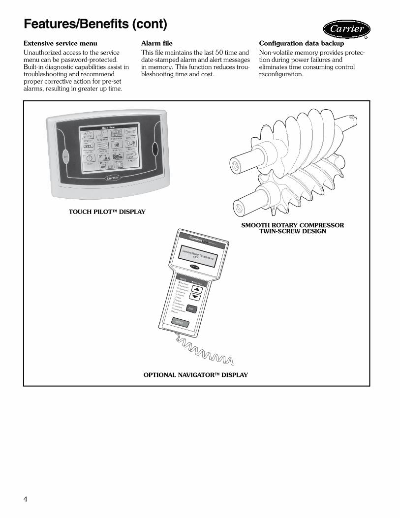
Two user interface options are avail-able, the Touch Pilot™ display and the Navigator™ module.
The Touch Pilot display is an easy to use touch screen display that provides simple navigation for configuration and control of the 30XW units.
Carrier's exclusive handheld Naviga-tor display provides convenience and powerful information in the palm of your hand. The Navigator display helps technicians to quickly diagnose prob-lems and even prevent them from occurring.
All 30XW units are ready to be used with Carrier Comfort Network® (CCN) devices.
Controls features include:Automatic capacity overrideThis function unloads the compressor whenever key safety limits are approached, increasing unit life.Chilled liquid resetReset can be accomplished manually or automatically from the building man-agement system. For a given capacity, reset allows operation at slower com-pressor speeds, saving energy when warmer chilled liquid can be used. Demand limitingThis feature limits the power draw of the chiller during peak loading condi-tions. When incorporated into the CCN building automation system, a red line command holds chillers at their present capacity and prevents any other chillers from starting. If a load shed signal is received, the compres-sors are unloaded to avoid demand charges whenever possible.Ramp loadingRamp loading ensures smooth pull-down of liquid loop temperature and prevents a rapid increase in compres-sor power consumption during the pulldown period.Automated controls testThe test can be executed prior to start-up to verify that the entire control sys-tem is functioning properly.365-day real time clockThis feature allows the operator to pro-gram a yearly schedule for each week, weekends, and holidays.Occupancy schedulesSchedules can be programmed into the controller to ensure that the chiller operates when cooling is required and remains off when not needed by the tenants or process.
4
Extensive service menuUnauthorized access to the service menu can be password-protected. Built-in diagnostic capabilities assist in troubleshooting and recommend proper corrective action for pre-set alarms, resulting in greater up time.
Alarm fileThis file maintains the last 50 time and date-stamped alarm and alert messages in memory. This function reduces trou-bleshooting time and cost.
Configuration data backupNon-volatile memory provides protec-tion during power failures and eliminates time consuming control reconfiguration.
Features/Benefits (cont)
Run StatusService TestTemperaturesPressures
SetpointsInputs
OutputsConfigurationTime Clock
Operating ModesAlarms
ENTER
ESC
MODEAlarm Status
ComfortLink
OPTIONAL NAVIGATOR™ DISPLAY
TOUCH PILOT™ DISPLAY
a30-3924
a30-4456
SMOOTH ROTARY COMPRESSORTWIN-SCREW DESIGN
30-562

5
Model number nomenclature
a30-4744
30XW – 325 6 – – – 4 – 3 B
30XW – AquaForce® Water-Cooled Screw Chiller
Design Series
Unit Size (Nominal Tons) (kW)325 – 325 (1133)350 – 350 (1206)400 – 400 (1354)
Voltage1 – 575-3-602 – 380-3-604 – 230-3-606 – 460-3-607 – 200-3-60
Condenser Options- – 2 Pass, NIH, 150 psig (1034 kPa), Victaulic, Discharge Connections (Std)0 – 2 Pass, NIH, 150 psig (1034 kPa), Victaulic, Suction Connections1 – 2 Pass, NIH, 150 psig (1034 kPa), Flange, Discharge Connections2 – 2 Pass, NIH, 150 psig (1034 kPa), Flange, Suction Connections3 – 2 Pass, NIH, 300 psig (2068 kPa), Victaulic, Discharge Connections4 – 2 Pass, NIH, 300 psig (2068 kPa), Victaulic, Suction Connections5 – 2 Pass, NIH, 300 psig (2068 kPa), Flange, Discharge Connections6 – 2 Pass, NIH, 300 psig (2068 kPa), Flange, Suction Connections7 – 2 Pass, MWB, 150 psig (1034 kPa), Victaulic, Discharge Connections8 – 2 Pass, MWB, 150 psig (1034 kPa), Victaulic, Suction Connections9 – 2 Pass, MWB, 300 psig (2068 kPa), Victaulic, Discharge ConnectionsB – 2 Pass, MWB, 300 psig (2068 kPa), Victaulic, Suction ConnectionsC – 2 Pass, MWB, 150 psig (1034 kPa), Flange, Discharge ConnectionsD – 2 Pass, MWB, 150 psig (1034 kPa), Flange, Suction ConnectionsF – 2 Pass, MWB, 300 psig (2068 kPa), Flange, Discharge ConnectionsG – 2 Pass, MWB, 300 psig (2068 kPa), Flange, Suction ConnectionsH – 1 Pass, NIH, 150 psig (1034 kPa), Flange, Discharge LeavingJ – 1 Pass, NIH, 300 psig (2068 kPa), Flange, Discharge LeavingK – 1 Pass, MWB, 150 psig (1034 kPa), Flange, Discharge LeavingL – 1 Pass, MWB, 300 psig (2068 kPa), Flange, Discharge Leaving
Heat Machine- – Std Condenser/Comfort Cooling (Std)M – Heat Machine Condenser/Comfort Cooling
Evaporator Options- – 2 Pass, NIH, 150 psig (1034 kPa), Victaulic, Discharge Connections (Std)0 – 2 Pass, NIH, 150 psig (1034 kPa), Victaulic, Suction Connections1 – 2 Pass, NIH, 150 psig (1034 kPa), Flange, Discharge Connections2 – 2 Pass, NIH, 150 psig (1034 kPa), Flange, Suction Connections3 – 2 Pass, NIH, 300 psig (2068 kPa), Victaulic, Discharge Connections4 – 2 Pass, NIH, 300 psig (2068 kPa), Victaulic, Suction Connections5 – 2 Pass, NIH, 300 psig (2068 kPa), Flange, Discharge Connections6 – 2 Pass, NIH, 300 psig (2068 kPa), Flange, Suction Connections7 – 2 Pass, MWB, 150 psig (1034 kPa), Victaulic, Discharge Connections8 – 2 Pass, MWB, 150 psig (1034 kPa), Victaulic, Suction Connections9 – 2 Pass, MWB, 300 psig (2068 kPa), Victaulic, Discharge ConnectionsB – 2 Pass, MWB, 300 psig (2068 kPa), Victaulic, Suction ConnectionsC – 2 Pass, MWB, 150 psig (1034 kPa), Flange, Discharge ConnectionsD – 2 Pass, MWB, 150 psig (1034 kPa), Flange, Suction ConnectionsF – 2 Pass, MWB, 300 psig (2068 kPa), Flange, Discharge ConnectionsG – 2 Pass, MWB, 300 psig (2068 kPa), Flange, Suction ConnectionsH – 1 Pass, NIH, 150 psig (1034 kPa), Flange, Discharge LeavingJ – 1 Pass, NIH, 300 psig (2068 kPa), Flange, Discharge LeavingK – 1 Pass, MWB, 150 psig (1034 kPa), Flange, Discharge LeavingL – 1 Pass, MWB, 300 psig (2068 kPa), Flange, Discharge LeavingM – 3 Pass, NIH, 150 psig (1034 kPa), Flange, Discharge LeavingN – 3 Pass, NIH, 150 psig (1034 kPa), Flange, Suction LeavingP – 3 Pass, NIH, 300 psig (2068 kPa), Flange, Discharge LeavingQ – 3 Pass, NIH, 300 psig (2068 kPa), Flange, Suction LeavingR – 3 Pass, MWB, 150 psig (1034 kPa), Flange, Discharge LeavingS – 3 Pass, MWB, 150 psig (1034 kPa), Flange, Suction LeavingT – 3 Pass, MWB, 300 psig (2068 kPa), Flange, Discharge LeavingV – 3 Pass, MWB, 300 psig (2068 kPa), Flange, Suction Leaving
Packaging/Charging OptionsB – R-134a Refrigerant with Bag (Std)C – R-134a Refrigerant with Crate Over Bag D – Nitrogen Refrigerant with BagF – Nitrogen Refrigerant with Crate Over Bag
Controls/Communications Options- – Navigator™ Display0 – Navigator Display, EMM1 – Navigator Display, GFCI Service Option2 – Navigator Display, EMM, GFCI Service Option3 – Touch Pilot™ Display (Std)4 – Touch Pilot, EMM5 – Touch Pilot, GFCI Service Option6 – Touch Pilot, EMM, GFCI Service Option7 – Navigator Display, BACnet™ Translator8 – Navigator Display, EMM, BACnet Translator9 – Navigator Display, GFCI Service Option,
BACnet TranslatorB – Navigator Display, EMM, GFCI Service Option,
BACnet TranslatorC – Touch Pilot Display (Std), BACnet TranslatorD – Touch Pilot Display, EMM, BACnet TranslatorF – Touch Pilot Display, GFCI Service Option,
BACnet TranslatorG – Touch Pilot Display, EMM, GFCI Service Option,
BACnet TranslatorH – Navigator Display, LON TranslatorJ – Navigator Display, EMM, LON TranslatorK – Navigator Display, GFCI Service Option,
LON TranslatorL – Navigator Display, EMM, GFCI Service Option,
LON TranslatorM – Touch Pilot Display (Std), LON TranslatorN – Touch Pilot Display, EMM, LON TranslatorP – Touch Pilot Display, GFCI Service Option,
LON TranslatorQ – Touch Pilot Display, EMM, GFCI Service
Option, LON Translator
Electrical Options- – Single Point, XL Starter, Terminal Block
(Std 380, 460, 575-v)0 – Single Point, Wye-Delta Starter, Terminal
Block (Std 200,230-v)3 – Dual Point, XL Starter, Terminal Block4 – Dual Point, Wye-Delta Starter, Terminal Block7 – Single Point, XL Starter, Non-Fused Disconnect8 – Single Point, Wye-Delta, Non-Fused DisconnectC – Dual Point, XL Starter, Non-Fused DisconnectD – Dual Point, Wye-Delta Starter, Non-Fused
DisconnectH – Single Point, XL Starter, Terminal Block, CPTJ – Single Point, Wye-Delta Starter, Terminal
Block, CPTM – Dual Point, XL Starter, Terminal Block, CPTN – Dual Point, Wye-Delta Starter, Terminal
Block, CPTR – Single Point, XL Starter, Non-Fused
Disconnect, CPTS – Single Point, Wye-Delta, Non-Fused
Disconnect, CPTW – Dual Point, XL Starter, Non-Fused
Disconnect, CPTX – Dual Point, Wye-Delta Starter, Non-Fused
Disconnect, CPT
Refrigeration Circuit Options*4 – Standard Unit 6 – With Suction Service ValvesD – With Minimum Load Control G – With Suction Service Valves and Minimum
Load Control N – With Condenser Insulation for Heat Machine Q – With Suction Service Valves and Condenser
Insulation for Heat Machine X – With Minimum Load Control and Condenser
Insulation for Heat Machine Z – With Suction Service Valves, Minimum Load
Control and Condenser Insulation for Heat Machine
LEGEND
*Evaporator insulation is standard.
Quality AssuranceCertified to ISO 9001:2000
CPT — Control Power Transformer MWB — Marine WaterboxEMM — Energy Management Module NIH — Nozzle-In-HeadGFCI — Ground Fault Circuit Interrupter XL — Across-the-Line StartLON — Local Operating Network

6
LEGEND
NOTES:1. Certified in accordance with AHRI Standard 550/590 at standard
rating conditions.2. Standard rating conditions are as follows:
Evaporator Conditions:Leaving Water Temperature: 44 F (6.7 C)Flow: 2.4 gpm per ton (0.043 L/s per kW)
Condenser Conditions:Entering Water Temperature:85 F (29.4 C)Flow: 3.0 gpm per ton (0.054 L/s per kW)
Fouling Factor (Evaporator):0.00010 hr x sq ft x F per Btuh (0.000018 m2 x K per W)
Fouling Factor (Condenser):0.00025 hr x sq ft x F per Btuh (0.000044 m2 x K per W)
3. IPLV is a single number part-load efficiency value calculated fromthe system full-load efficiency values and corrected for a typicalbuilding air-conditioning application.
4. Contact Carrier for custom ratings.5. Data shown for standard chiller with 2 pass, nozzle-in-head (NIH)
waterboxes.
30XW UNIT SIZE
CAPACITY INPUT POWER
(kW)
EVAPORATOR FLOW
EVAPORATOR PRESSURE DROP
CONDENSER FLOW
CONDENSER PRESSURE DROP FULL LOAD
EFFICIENCY (kW/Ton)
IPLV(kW/Ton)
Tons Output (kW) gpm L/s Ft of
Water kPa gpm L/s Ft of Water kPa
325 322 1132.5 204.8 773 48.8 15.6 46.5 967 61.0 10.9 32.5 0.636 0.468350 343 1206.3 215.7 824 52.0 17.5 52.2 1029 64.9 12.3 36.7 0.629 0.471400 385 1354.0 242.8 924 58.3 21.5 64.1 1155 72.9 15.2 45.3 0.631 0.474
AHRI — Air Conditioning, Heating and Refrigeration InstituteIPLV — Integrated Part Load Value
Capacity ratings
7
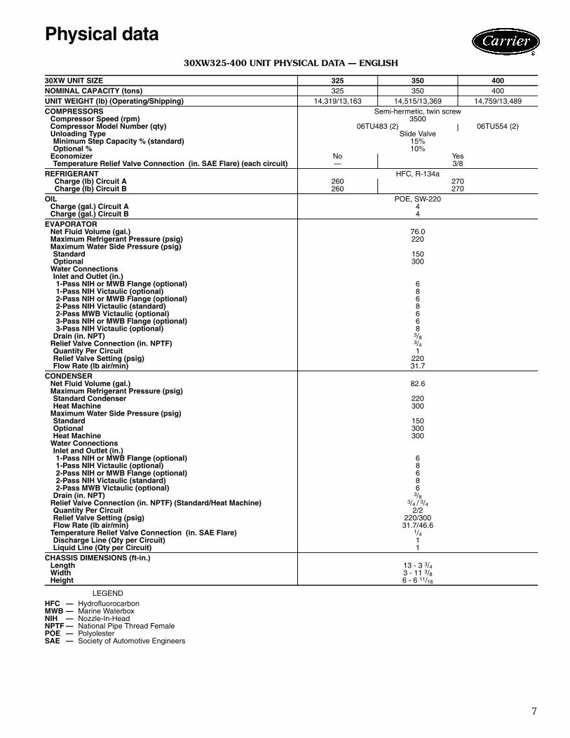
30XW325-400 UNIT PHYSICAL DATA — ENGLISH
LEGEND
30XW UNIT SIZE 325 350 400NOMINAL CAPACITY (tons) 325 350 400UNIT WEIGHT (lb) (Operating/Shipping) 14,319/13,163 14,515/13,369 14,759/13,489COMPRESSORS Semi-hermetic, twin screw
Compressor Speed (rpm) 3500Compressor Model Number (qty) 06TU483 (2) 06TU554 (2)Unloading Type Slide ValveMinimum Step Capacity % (standard) 15%Optional % 10%
Economizer No YesTemperature Relief Valve Connection (in. SAE Flare) (each circuit) — 3/8
REFRIGERANT HFC, R-134a Charge (lb) Circuit A 260 270 Charge (lb) Circuit B 260 270
OIL POE, SW-220Charge (gal.) Circuit A 4Charge (gal.) Circuit B 4
EVAPORATORNet Fluid Volume (gal.) 76.0Maximum Refrigerant Pressure (psig) 220Maximum Water Side Pressure (psig)Standard 150Optional 300
Water ConnectionsInlet and Outlet (in.)1-Pass NIH or MWB Flange (optional) 61-Pass NIH Victaulic (optional) 82-Pass NIH or MWB Flange (optional) 62-Pass NIH Victaulic (standard) 82-Pass MWB Victaulic (optional) 63-Pass NIH or MWB Flange (optional) 63-Pass NIH Victaulic (optional) 8
Drain (in. NPT) 3/8Relief Valve Connection (in. NPTF) 3/4Quantity Per Circuit 1Relief Valve Setting (psig) 220Flow Rate (lb air/min) 31.7
CONDENSERNet Fluid Volume (gal.) 82.6Maximum Refrigerant Pressure (psig)Standard Condenser 220Heat Machine 300
Maximum Water Side Pressure (psig)Standard 150Optional 300Heat Machine 300
Water ConnectionsInlet and Outlet (in.) 1-Pass NIH or MWB Flange (optional) 61-Pass NIH Victaulic (optional) 82-Pass NIH or MWB Flange (optional) 62-Pass NIH Victaulic (standard) 82-Pass MWB Victaulic (optional) 6
Drain (in. NPT) 3/8Relief Valve Connection (in. NPTF) (Standard/Heat Machine) 3/4 / 3/4Quantity Per Circuit 2/2Relief Valve Setting (psig) 220/300Flow Rate (lb air/min) 31.7/46.6
Temperature Relief Valve Connection (in. SAE Flare) 1/4Discharge Line (Qty per Circuit) 1Liquid Line (Qty per Circuit) 1
CHASSIS DIMENSIONS (ft-in.)Length 13 - 3 3/4Width 3 - 11 3/8Height 6 - 6 11/16
HFC — HydrofluorocarbonMWB — Marine WaterboxNIH — Nozzle-In-HeadNPTF — National Pipe Thread FemalePOE — PolyolesterSAE — Society of Automotive Engineers
Physical data
8
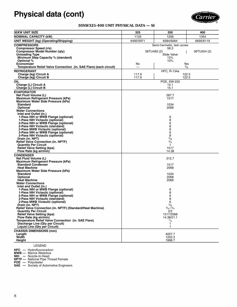
30XW325-400 UNIT PHYSICAL DATA — SI
LEGEND
30XW UNIT SIZE 325 350 400NOMINAL CAPACITY (kW) 1133 1206 1354UNIT WEIGHT (kg) (Operating/Shipping) 6495/5971 6584/6064 6695/6119COMPRESSORS Semi-hermetic, twin screw
Compressor Speed (r/s) 58.3Compressor Model Number (qty) 06TU483 (2) 06TU554 (2)Unloading Type Slide ValveMinimum Step Capacity % (standard) 15%Optional % 10%
Economizer No YesTemperature Relief Valve Connection (in. SAE Flare) (each circuit) — 3/8
REFRIGERANT HFC, R-134a Charge (kg) Circuit A 117.9 122.5 Charge (kg) Circuit B 117.9 122.5
OIL POE, SW-220Charge (L) Circuit A 15.1Charge (L) Circuit B 15.1
EVAPORATORNet Fluid Volume (L) 287.7Maximum Refrigerant Pressure (kPa) 1517Maximum Water Side Pressure (kPa)Standard 1034Optional 2068
Water ConnectionsInlet and Outlet (in.)1-Pass NIH or MWB Flange (optional) 61-Pass NIH Victaulic (optional) 82-Pass NIH or MWB Flange (optional) 62-Pass NIH Victaulic (standard) 82-Pass MWB Victaulic (optional) 63-Pass NIH or MWB Flange (optional) 63-Pass NIH Victaulic (optional) 8
Drain (in. NPT) 3/8Relief Valve Connection (in. NPTF) 3/4Quantity Per Circuit 1Relief Valve Setting (kpa) 1517Flow Rate (kg air/min) 14.38
CONDENSERNet Fluid Volume (L) 312.7Maximum Refrigerant Pressure (kPa)Standard Condenser 1517Heat Machine 2068
Maximum Water Side Pressure (kPa)Standard 1034Optional 2068Heat Machine 2068
Water ConnectionsInlet and Outlet (in.) 1-Pass NIH or MWB Flange (optional) 61-Pass NIH Victaulic (optional) 82-Pass NIH or MWB Flange (optional) 62-Pass NIH Victaulic (standard) 82-Pass MWB Victaulic (optional) 6
Drain (in. NPT) 3/8Relief Valve Connection (in. NPTF) (Standard/Heat Machine) 3/4 / 3/4Quantity Per Circuit 2/2Relief Valve Setting (kpa) 1517/2068Flow Rate (kg air/min) 14.38/21.1
Temperature Relief Valve Connection (in. SAE Flare) 1/4Discharge Line (Qty per Circuit) 1Liquid Line (Qty per Circuit) 1
CHASSIS DIMENSIONS (mm)Length 4057.7Width 1203.3Height 1998.7
HFC — HydrofluorocarbonMWB — Marine WaterboxNIH — Nozzle-In-HeadNPTF — National Pipe Thread FemalePOE — PolyolesterSAE — Society of Automotive Engineers
Physical data (cont)
9
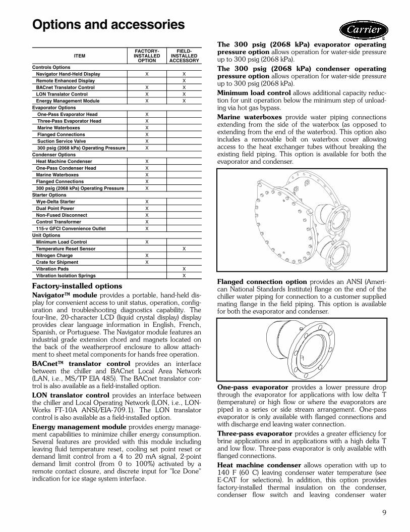
Factory-installed optionsNavigator™ module provides a portable, hand-held dis-play for convenient access to unit status, operation, config-uration and troubleshooting diagnostics capability. Thefour-line, 20-character LCD (liquid crystal display) displayprovides clear language information in English, French,Spanish, or Portuguese. The Navigator module features anindustrial grade extension chord and magnets located onthe back of the weatherproof enclosure to allow attach-ment to sheet metal components for hands free operation.BACnet™ translator control provides an interfacebetween the chiller and BACnet Local Area Network(LAN, i.e., MS/TP EIA 485). The BACnet translator con-trol is also available as a field-installed option.LON translator control provides an interface betweenthe chiller and Local Operating Network (LON, i.e., LON-Works FT-10A ANSI/EIA-709.1). The LON translatorcontrol is also available as a field-installed option.Energy management module provides energy manage-ment capabilities to minimize chiller energy consumption.Several features are provided with this module includingleaving fluid temperature reset, cooling set point reset ordemand limit control from a 4 to 20 mA signal, 2-pointdemand limit control (from 0 to 100%) activated by aremote contact closure, and discrete input for "Ice Done"indication for ice stage system interface.
The 300 psig (2068 kPa) evaporator operatingpressure option allows operation for water-side pressureup to 300 psig (2068 kPa).The 300 psig (2068 kPa) condenser operatingpressure option allows operation for water-side pressureup to 300 psig (2068 kPa).Minimum load control allows additional capacity reduc-tion for unit operation below the minimum step of unload-ing via hot gas bypass.Marine waterboxes provide water piping connectionsextending from the side of the waterbox (as opposed toextending from the end of the waterbox). This option alsoincludes a removable bolt on waterbox cover allowingaccess to the heat exchanger tubes without breaking theexisting field piping. This option is available for both theevaporator and condenser.
Flanged connection option provides an ANSI (Ameri-can National Standards Institute) flange on the end of thechiller water piping for connection to a customer suppliedmating flange in the field piping. This option is availablefor both the evaporator and condenser.
One-pass evaporator provides a lower pressure dropthrough the evaporator for applications with low delta T(temperature) or high flow or where the evaporators arepiped in a series or side stream arrangement. One-passevaporator is only available with flanged connections andwith discharge end leaving water connection.Three-pass evaporator provides a greater efficiency forbrine applications and in applications with a high delta Tand low flow. Three-pass evaporator is only available withflanged connections.Heat machine condenser allows operation with up to140 F (60 C) leaving condenser water temperature (seeE-CAT for selections). In addition, this option providesfactory-installed thermal insulation on the condenser,condenser flow switch and leaving condenser water
ITEMFACTORY-INSTALLED
OPTION
FIELD-INSTALLED
ACCESSORYControls Options Navigator Hand-Held Display X X Remote Enhanced Display X BACnet Translator Control X X LON Translator Control X X Energy Management Module X XEvaporator Options One-Pass Evaporator Head X Three-Pass Evaporator Head X Marine Waterboxes X Flanged Connections X Suction Service Valve X 300 psig (2068 kPa) Operating Pressure XCondenser Options Heat Machine Condenser X One-Pass Condenser Head X Marine Waterboxes X Flanged Connections X 300 psig (2068 kPa) Operating Pressure XStarter Options Wye-Delta Starter X Dual Point Power X Non-Fused Disconnect X Control Transformer X 115-v GFCI Convenience Outlet XUnit Options Minimum Load Control X Temperature Reset Sensor X Nitrogen Charge X Crate for Shipment X Vibration Pads X Vibration Isolation Springs X
Options and accessories
a30-4684.eps
a30-4685

10
temperature sensor to facilitate operating in HEAT mode.Heat machine units require 300 psig (2068 kPa) optionand field-installed thermal insulation on the compressordischarge piping and waterbox heads because of hightemperature.One-pass condenser provides a lower pressure dropthrough the condenser for applications with low delta T(temperature) or high flow or where the condensers arepiped in a series. The one-pass condenser option is onlyavailable with flanged connections and with a dischargeend leaving water connection.Wye-delta start is an alternate starting method whichreduces the inrush current when starting the compressor.Wye delta start is standard on 208-v, and 230-v units,optional for 380-v, 460-v, and 575-v. Dual point power provides a means for connecting twosources of power to dual compressor 30XW chillers. Onesource of power is wired to operate the compressor on theA circuit and one source of power is wired to operate thecompressor on the B circuit of the chiller. Non-fused disconnect provides a no load, lockable,through the door handle disconnect for unit power on thechiller. On dual point power, one disconnect is provided foreach of the two main power supplies. This disconnect doesnot remove the control circuit from power supply. Control transformer is sized to supply the needs of thecontrol circuit from the main power supply. 115-v GFCI convenience outlet includes 4 amp GFI(ground fault interrupt) receptacle. Convenience outlet is115-v female receptacle. Not available with 380-v units.Nitrogen charge provides a 15 lb (6.8 kg) charge ofnitrogen instead of a full factory charge of R-134a refrig-erant to keep the chiller refrigerant circuit dry during ship-ment. This option is recommended for applications wherethe unit will be disassembled prior to installation. Unitsshipped with a nitrogen charge will receive an electricalcontinuity test at the factory prior to shipment.Crate for shipment provides a wooden crate around thechiller. The chiller is bagged prior to being placed in thecrate. This option is recommended for export orders.Suction service valves allow for further isolation of thecompressor from the evaporator vessel.
Field-installed accessoriesRemote enhanced display is a remotely mountedindoor 40-character per line, 16-line display panel for unitmonitoring and diagnostics.
BACnet™ translator control provides an interfacebetween the chiller and BACnet Local Area Network(LAN, i.e., MS/TP EIA 485). The BACnet translator con-trol is also available as a factory-installed option.LON translator control provides an interface betweenthe chiller and Local Operating Network (LON, i.e., LON-Works FT-10A ANSI/EIA-709.1). The LON translatorcontrol is also available as a factory-installed option.Energy management module provides energy manage-ment capabilities to minimize chiller energy consumption.Several features are provided with this module includingleaving fluid temperature reset, cooling set point reset ordemand limit control from a 4 to 20 mA signal, 2-pointdemand limit control (from 0 to 100%) activated by aremote contact closure, and discrete input for "Ice Done"indication for ice stage system interface.Temperature reset sensor provides temperature resetcapability from either the occupied space or outdoor tem-perature sensor.NOTE: Temperature reset capability using return tempera-ture is standard.Vibration isolation pads are neoprene pads for installa-tion under the chiller feet at the jobsite.Vibration springs provide a set of non-siesmic springisolators for installation at the jobsite.Navigator™ module provides a portable, hand-held dis-play for convenient access to unit status, operation, config-uration and troubleshooting diagnostics capability. Thefour-line, 20-character LCD (liquid crystal display) displayprovides clear language information in English, French,Spanish, or Portuguese. The Navigator module features anindustrial grade extension chord and magnets located onthe back of the weatherproof enclosure to allow attach-ment to sheet metal components for hands free operation.
Field-supplied and field-installed insulationEvaporator waterbox insulation must be field installed.When insulating waterboxes, allow for service access andremoval of covers. To estimate waterbox cover areas, referto the following figure.Insulation for discharge piping between the compres-sor and condenser must be field installed on heat machineunits. Refer to the following figure.Condenser waterbox insulation must be field installedon heat machine units. When insulating waterboxes, allowfor service access and removal of covers. To estimatewaterbox cover areas, refer to the following figure.
Options and accessories (cont)

11
FIELD-SUPPLIED AND FIELD-INSTALLED INSULATION
CONDENSER WATERBOXINSULATION NEEDED (HEATMACHINE UNITS ONLY)
CONDENSER WATERBOXINSULATION NEEDED (HEATMACHINE UNITS ONLY)
EVAPORATOR WATERBOXINSULATION NEEDED
EVAPORATOR WATERBOXINSULATION NEEDED
EVAPORATOR WATERBOXINSULATION NEEDED
DISCHARGE PIPINGINSULATION NEEDED (HEATMACHINE UNITS ONLY)
NOTES:1. Field-installed insulation for standard units shown in light gray.2. Field-installed insulation for heat machine units shown in dark gray.3. Back of the unit shown.
a30-4686
12
Dimensions
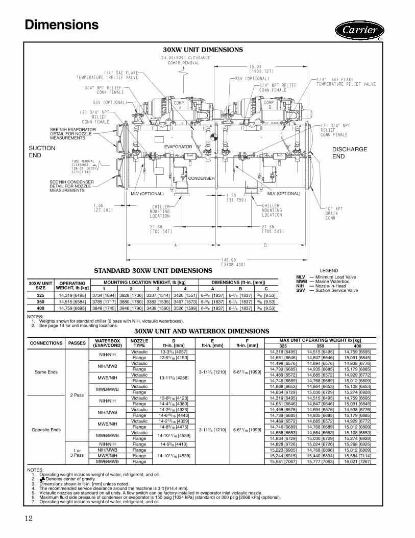
30XW UNIT DIMENSIONS
30XW UNIT AND WATERBOX DIMENSIONS
NOTES:1. Operating weight includes weight of water, refrigerent, and oil.2. Denotes center of gravity.3. Dimensions shown in ft-in. [mm] unless noted.4. The recommended service clearance around the machine is 3 ft [914.4 mm].5. Victaulic nozzles are standard on all units. A flow switch can be factory-installed in evaporator inlet victaulic nozzle.6. Maximum fluid side pressure of condenser or evaporator is 150 psig [1034 kPa] (standard) or 300 psig [2068 kPa] (optional).7. Operating weight includes weight of water, refrigerant, and oil.
CONNECTIONS PASSES WATERBOX (EVAP/COND)
NOZZLETYPE
Dft-in. [mm]
Eft-in. [mm]
Fft-in. [mm]
MAX UNIT OPERATING WEIGHT lb [kg]325 350 400
Same Ends
2 Pass
NIH/NIHVictaulic 13-33/4 [4057]
3-113/8 [1210] 6-611/16 [1999]
14,319 [6495] 14,515 [6495] 14,759 [6695]Flange 13-91/16 [4193] 14,651 [6646] 14,847 [6646] 15,091 [6845]
NIH/MWBVictaulic
13-115/8 [4258]
14,498 [6576] 14,694 [6576] 14,938 [6776]Flange 14,739 [6685] 14,935 [6685] 15,179 [6885]
MWB/NIHVictaulic 14,489 [6572] 14,685 [6572] 14,929 [6772]Flange 14,746 [6689] 14,768 [6689] 15,012 [6809]
MWB/MWBVictaulic 14,668 [6653] 14,864 [6653] 15,108 [6853]Flange 14,834 [6729] 15,030 [6729] 15,274 [6928]
Opposite Ends
NIH/NIHVictaulic 13-65/16 [4123]
3-113/8 [1210] 6-611/16 [1999]
14,319 [6495] 14,515 [6495] 14,759 [6695]Flange 14-47/16 [4380] 14,651 [6646] 14,847 [6646] 15,091 [6845]
NIH/MWBVictaulic 14-23/16 [4323] 14,498 [6576] 14,694 [6576] 14,938 [6776]Flange 14-615/16 [4443] 14,739 [6685] 14,935 [6685] 15,179 [6885]
MWB/NIHVictaulic 14-213/16 [4339] 14,489 [6572] 14,685 [6572] 14,929 [6772]Flange 14-83/16 [4475] 14,746 [6689] 14,768 [6689] 15,012 [6809]
MWB/MWBVictaulic
14-1011/16 [4539]14,668 [6653] 14,864 [6653] 15,108 [6853]
Flange 14,834 [6729] 15,030 [6729] 15,274 [6928]
1 or3 Pass
NIH/NIH Flange 14-55/8 [4410] 14,828 [6726] 15,024 [6726] 15,268 [6925]NIH/MWB Flange
14-1011/16 [4539]15,223 [6905] 14,768 [6896] 15,012 [6809]
MWB/NIH Flange 15,244 [6915] 15,440 [6894] 15,684 [7114]MWB/MWB Flange 15,581 [7067] 15,777 [7063] 16,021 [7267]
SUCTIONEND
DISCHARGEEND
EVAPORATOR
CONDENSERSEE NIH CONDENSERDETAIL FOR NOZZLEMEASUREMENTS
SEE NIH EVAPORATORDETAIL FOR NOZZLEMEASUREMENTS
MLV (OPTIONAL) MLV (OPTIONAL)
a30-4745
STANDARD 30XW UNIT DIMENSIONS
NOTES:1. Weights shown for standard chiller (2 pass with NIH, victaulic waterboxes).2. See page 14 for unit mounting locations.
30XW UNIT SIZE
OPERATING WEIGHT, lb [kg]
MOUNTING LOCATION WEIGHT, lb [kg] DIMENSIONS (ft-in. [mm])1 2 3 4 A B C
325 14,319 [6495] 3734 [1694] 3828 [1736] 3337 [1514] 3420 [1551] 6-3/8 [1837] 6-3/8 [1837] 3/8 [9.53]
350 14,515 [6584] 3785 [1717] 3880 [1760] 3383 [1535] 3467 [1573] 6-3/8 [1837] 6-3/8 [1837] 3/8 [9.53]
400 14,759 [6695] 3848 [1745] 3946 [1790] 3439 [1560] 3526 [1599] 6-3/8 [1837] 6-3/8 [1837] 3/8 [9.53]
LEGEND
MLV — Minimum Load ValveMWB — Marine WaterboxNIH — Nozzle-In-HeadSSV — Suction Service Valve

13
30X
W U
NIT
DIM
EN
SIO
NS (co
nt)
D
DIS
CH
AR
GE
EN
DS
UC
TIO
NE
ND
a30-
4747
INC
OM
ING
CO
NTR
OL
INC
OM
ING
CO
NTR
OL
POW
ER 1
x 7
/8”
POW
ER 1
x 7
/8”
KN
OC
KOU
TK
NO
CKO
UT
DO
OR
CLE
ARA
NC
E SP
AC
ED
OO
R C
LEA
RA
NC
E SP
AC
E
DIS
CH
AR
GE
EN
D
SU
CT
ION
EN
D
a30-
4748
EVA
P 3 3/
16”
[81
mm
]
a30-4755

14
Dimensions (cont)
30XW UNIT DIMENSIONS (cont)
WATERBOX FLANGE DETAIL
a30-4725
UNIT NUMBER OF PASSES
Ain. (mm)
Bin. (mm)
CONNECTION SIZE
Flange Victaulic
30XW325-400
2 61/16 (154) 61/16 (154) 6 8
1 0 (0) 0 (0) 6 8
3 61/16 (154) 61/16 (154) 6 8
UNIT NUMBER OF PASSES
Ain. (mm)
Bin. (mm)
CONNECTION SIZE
Flange Victaulic
30XW325-400
2 71/2 (191) 71/2 (191) 6 6
1 0 (0) 0 (0) 6 —
3 71/2 (191) 71/2 (191) 6 —
UNIT NUMBER OF PASSES
Ain. (mm)
Bin. (mm)
CONNECTION SIZE
Flange Victaulic
30XW325-4002 63/4 (171) 63/4 (171) 6 8
1 0 (0) 0 (0) 6 8
UNIT NUMBER OF PASSES
Ain. (mm)
Bin. (mm)
CONNECTION SIZE
Flange Victaulic
30XW325-4002 73/8 (187) 73/8 (187) 6 6
1 0 (0) 0 (0) 6 —
NIH EVAPORATOR
DISCHARGE DISCHARGEDISCHARGE
SUCTION SUCTIONSUCTION
a30-4751NIH CONDENSER
DISCHARGE
SUCTION
DISCHARGE
SUCTION
a30-4749
MARINE EVAPORATOR
DISCHARGE DISCHARGEDISCHARGE
SUCTION SUCTIONSUCTION
a30-4752MARINE CONDENSER
DISCHARGE DISCHARGE
SUCTION SUCTION
a30-4750
MOUNTINGLOCATIONS a30-4688

15
Carrier’s packaged selection program provides quick,easy selection of Carrier’s water-cooled chillers. The pro-gram considers specific temperature, fluid and flowrequirements among other factors such as fouling and alti-tude corrections.
Before selecting a chiller, consider the following points:Leaving water (fluid) temperature (LWT)• The LWT must be at least 40 F (4.4 C) or greater.• If the LWT requirement is greater than 60 F (15.5 C), a
mixing loop is required.Entering water (fluid) temperature (EWT)• If the EWT requirement is greater than 70 F (21.1 C), a
mixing loop is required. The EWT should not exceed70 F (21.1 C) for extended operation. Pulldown can beaccomplished from 95 F (35 C).
Evaporator flow rate or evaporator delta-T:• The evaporator delta-T (EWT – LWT) must fall between
5 and 20° F (2.8 and 11.1° C) while still meeting themaximum entering requirements.
• For larger or smaller delta-T applications, a mixing loopis required. If the evaporator flow is variable, the rate ofchange of flow should not exceed 10% per minute.The loop volume in circulation must equal or exceed3 gallons per nominal ton (3.2 L per kW) of cooling fortemperature stability and accuracy in normal air condi-tioning applications. In process cooling applications,there should be 6 to 10 gallons per ton (6.5 to 10.8 Lper kW). To achieve this loop volume, it is often neces-sary to install a tank in the loop. The tank should be baf-fled to ensure there is no stratification, and that water(or brine) entering the tank is adequately mixed with liq-uid in the tank. See Water Loop Volume in the Applica-tion Data section.
Evaporator pressure drop:• A high evaporator pressure drop can be expected when
the evaporator delta-T is low. A mixing loop can help toalleviate this situation.
• The three-pass evaporator option is recommended toincrease performance when the evaporator delta T ishigh. This is particularly helpful with brine applications.
Condenser pressure drop:• A high condenser pressure drop can be expected when
the condenser delta-T is low. A one-pass condenser canhelp lower pressure drop.
Series chillers:• One-pass heat exchangers can help lower pressure
drop when heat exchangers are placed in series.Water quality, fouling factor:• Poor water quality can increase the required evaporator
fouling factor.• Higher than standard fouling factors lead to lower
capacity and higher input kW from a given chiller sizecompared to running the same application with betterwater quality (and lower fouling factors).
Temperature reset:• Return water (standard)• Outside air temperature (standard)• Space temperature (accessory sensor required)• 4 to 20 mA (requires an energy management module)Demand limit:• 2-step (requires an energy management module)• 4 to 20 mA (requires an energy management module)• CCN Loadshed
Performance dataEVAPORATOR AND CONDENSER FLOW RATES
*Maximum condenser fluid temperature shown for standard condensingoption. Heat machine option may have leaving fluid temperatures up to140 F (60 C).
30XW UNIT
EVAPORATOR CONDENSER NOMINALLeaving Fluid/Entering Fluid Minimum Entering
FluidMaximum Leaving
FluidEvaporator CondenserMinimum Maximum
40 F (4.4 C)/45 F (7.2 C)
60 F (15.6 C)/70 F (21.1 C) 65 F (18.3 C) 118 F (47.8 C)*
MinimumFlow Rate
MaximumFlow Rate
MinimumFlow Rate
MaximumFlow Rate
NominalFlow Rate
NominalFlow Rate
GPM L/s GPM L/s GPM L/s GPM L/s GPM L/s GPM L/s
325Two pass 411 25.9 1481 93.4 494 31.1 1974 124.5 790 49.8 987 62.3One pass 790 49.8 3126 197.2 987 62.3 3290 207.6 790 49.8 987 62.3
Three pass 247 15.6 987 62.3 — — — — 790 49.8 — —
350Two pass 433 27.3 1557 98.2 519 32.7 2076 131.0 830 52.4 1038 65.5One pass 830 52.4 3287 207.4 1038 65.5 3460 218.3 830 52.4 1038 65.5
Three pass 260 16.4 1038 65.5 — — — — 830 52.4 — —
400Two pass 486 30.7 1751 110.4 584 36.8 2334 147.3 934 58.9 1167 73.6One pass 934 58.9 3696 233.1 1167 73.6 3890 245.4 934 58.9 1167 73.6
Three pass 292 18.4 1167 73.6 — — — — 934 58.9 — —
Selection procedure

16
Performance data (cont)
30XW325-400 EVAPORATOR MARINE WATERBOX
0 500 1000 1500 2000 2500 3000(0) (31.5) (63.1) (94.6) (126.2) (157.7) (189.3)
3
21
pass
passpass
gpm(L/s)
Evaporator Flow Rate
0.00
5.00
10.00
15.00
20.00
25.00
30.00
35.00
40.00
ft wg
(0)
(14.9)
(29.8)
(44.8)
(59.7)
(74.6)
(89.5)
(104.4)
(119.4)
(kPa)
Pre
ssu
re D
rop
NOTE: The table above represents pressure drops only. The table does not imply that the chiller can be properly applied overthe entire range of evaporator water flow rates represented. A30-4691
0 500 1000 1500 2000(0) (31.5) (63.1) (94.6) (126.2)
Evaporator Flow Rate
3
2
1 pass
pass
pass
0.00
5.00
10.00
15.00
20.00
25.00
30.00
35.00
40.00
ft wg
gpm(L/s)
(0)
(14.9)
(29.8)
(44.8)
(59.7)
(74.6)
(89.5)
(104.4)
(119.4)
(kPa)
Pre
ssu
re D
rop
LEGEND
NOTE: The table above represents pressure drops only. The table does not imply that the chiller can be properly applied over theentire range of evaporator water flow rates represented.
NIH — Nozzle-In-Head
30XW325-400 EVAPORATOR NIH FLANGE
A30-4692

17
3
0 500 1000 1500 2000 2500 3000(0) (31.5) (63.1) (94.6) (126.2) (157.7) (189.3)
Evaporator Flow Rate
2 1
pass
pass pass
0.00
5.00
10.00
15.00
20.00
25.00
30.00
35.00
40.00
ft wg
(0)
(14.9)
(29.8)
(44.8)
(59.7)
(74.6)
(89.5)
(104.4)
(119.4)
(kPa)P
ress
ure
Dro
p
gpm(L/s)
30XW325-400 EVAPORATOR NIH VICTAULIC
LEGEND
NOTE: The table above represents pressure drops only. The table does not imply that the chiller can be properly applied over theentire range of evaporator water flow rates represented.
NIH — Nozzle-In-Head A30-4693
0.00
5.00
10.00
15.00
20.00
25.00
30.00
35.00
40.00
ft wg
gpm(L/s)
(0)
(14.9)
(29.8)
(44.8)
(59.7)
(74.6)
(89.5)
(104.4)
(119.4)
(kPa)
0 500 1000 1500 2000 2500 3000 3500(0) (31.5) (63.1) (94.6) (126.2) (157.7) (189.3) (220.8)
Condenser Flow Rate
Pre
ssu
re D
rop
2 pass1 pass
NOTE: The table above represents pressure drops only. The table does not imply that the chiller can be properly applied over theentire range of condenser water flow rates represented.
30XW325-400 CONDENSER MARINE WATERBOX
A30-4694
18
Performance data (cont)
0.00
5.00
10.00
15.00
20.00
25.00
30.00
35.00
40.00
ft wg
(0)
(14.9)
(29.8)
(44.8)
(59.7)
(74.6)
(89.5)
(104.4)
(119.4)
(kPa)
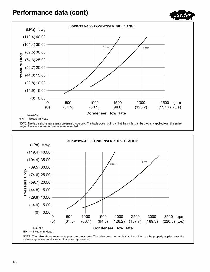
0 500 1000 1500 2000 2500 (0) (31.5) (63.1) (94.6) (126.2) (157.7)
Condenser Flow Rate
Pre
ssu
re D
rop
2 pass 1 pass
gpm(L/s)
30XW325-400 CONDENSER NIH FLANGE
LEGEND
NOTE: The table above represents pressure drops only. The table does not imply that the chiller can be properly applied over the entirerange of evaporator water flow rates represented.
NIH — Nozzle-In-Head A30-4695
2 pass1 pass
0.00
5.00
10.00
15.00
20.00
25.00
30.00
35.00
40.00
ft wg
gpm(L/s)
(0)
(14.9)
(29.8)
(44.8)
(59.7)
(74.6)
(89.5)
(104.4)
(119.4)
(kPa)
0 500 1000 1500 2000 2500 3000 3500(0) (31.5) (63.1) (94.6) (126.2) (157.7) (189.3) (220.8)
Condenser Flow Rate
Pre
ssu
re D
rop
30XW325-400 CONDENSER NIH VICTAULIC
LEGEND
NOTE: The table above represents pressure drops only. The table does not imply that the chiller can be properly applied over theentire range of evaporator water flow rates represented.
NIH — Nozzle-In-Head A30-4696

19
MicroprocessorThe chiller microprocessor controls overall unit operationand controls a number of processes simultaneously. Theseprocesses include internal timers, reading inputs, analog todigital conversions, display control, diagnostic control, out-put relay control, demand limit, capacity control, headpressure control, and temperature reset. Some processesare updated almost continuously, others every 2 to 3 sec-onds, and some every 30 seconds. The microprocessorroutine is started by switching the emergency ON-OFFswitch to the ON position.
Control sequencePre-start — After control switches on, the prestart takesplace. The microprocessor checks itself, and if configured,energizes the evaporator and condenser pumps to theinternal (or CCN) time schedule (or input occupied signalfrom an external system) and waits for temperature tostabilize.Start-up — The chiller will receive a call for cooling whenchilled fluid temperature increases above the set point plusa dead band, or if an override start command is received.If flow has been proven, the first compressor starts 1 to 3minutes after the call for cooling. The controlled pulldownfeature limits compressor loading on start up to reducedemand on start up and unnecessary compressor usage.Capacity control — On the first call for cooling, themicroprocessor starts the compressor on the lead circuit.The microprocessor maintains leaving fluid temperatureset point through intelligent positioning of the slide valve.As the load increases above the compressor's capacity, thecompressor on the lag circuit is started and both compres-sors are staged together. Maintaining set point — The control monitors enteringand leaving chilled water temperature to anticipatechanges in cooling load. The speed at which capacity isadded or reduced is controlled by temperature deviationfrom set point and rate of temperature change of thechilled fluid. The basic logic for determining when to addor remove capacity is a time band integration of deviationfrom set point plus rate of change of leaving fluid tempera-ture. When leaving-fluid temperature is close to the setpoint and slowly moving closer, logic prevents additionalcapacity. Accuracy depends on loop volume, loop flowrate, load and condenser water temperatures.Return fluid temperature compensation — No adjust-ment for cooling range or evaporator flow rate is requiredbecause the control automatically compensates for coolingrange by measuring both return fluid temperature and leav-ing fluid temperature.Low temperature override — This feature preventsLWT (leaving water temperature) from overshooting theset point to prevent nuisance low suction temperaturetrips.High temperature override — This feature allows thechiller to add capacity quickly during rapid load variations.Temperature reset (chilled water reset) — Whenlatent loads in the conditioned space are reduced, it may bepossible to reset the leaving chilled water temperature set
point to a warmer temperature thereby reducing compres-sor power usage and saving energy. Three reset optionsare offered. With any chilled water reset application, hu-midity control should be considered since higher coil tem-peratures will reduce latent capacity. For details on apply-ing a reset option, refer to the Controls, Start-Up, Opera-tion, Service and Troubleshooting guide. Return fluid temperature reset — This featureincreases LWT set point as return (entering) fluid tempera-ture decreases (indicating load decrease). This option maybe used where return fluid temperature provides accurateload indication. No additional hardware is required.Outdoor-air temperature reset — This featureincreases LWT set point as outdoor ambient temperaturesdecreases (indicating load decrease). This reset should onlybe applied where outdoor ambient temperature is an indi-cation of load. A field-installed thermistor is required.Space temperature reset — This feature increases theLWT as space temperature decreases (indicating loaddecrease). This reset should only be applied where spacetemperature is an indication of load. A field-supplied ther-mistor is required.Minimum load control — The main base board (MBB)responds to the supply chilled water temperature to matchcooling load requirements and controls the minimum loadcontrol valve. The minimum load control valve allows hotgas to pass directly into the evaporator circuit permittingthe unit to operate at lower loads with less compressorcycling. Minimum load control should be given consider-ation when operation is anticipated below the minimumunloading step.Pull down control — If pulldown control has beenselected (adjustable setting), no additional capacity is addedas long as the difference between fluid temperature and theset point is greater than 4 F (2.2 C) and rate of change inleaving water temperature is greater than the 90 secondssince the last capacity change, compressors will continueto run unless a safety device trips. This prevents rapidcycling and also helps return oil during short operatingperiods.Maximum operating pressure control — If the enter-ing fluid temperature is 95 F (35 C) and the saturated suc-tion temperature is 50 F (10 C) or higher, the maximumoperating pressure (MOP) feature limits the suction to keepthe chiller online. The control automatically starts thechiller in the unloaded state to eliminate the potential ofcompressor overload due to high head pressure or low suc-tion pressure.Equalized run time — The controller will equalize runtime on each circuit through the lead / lag feature. If a cir-cuit becomes disabled, the control will automatically set theactive circuit to lead, keeping the chiller online at a reducedcapacity.Sensors — Thermistors are used to control temperaturesensing inputs to the microprocessor. No additional ther-mistor sensors are required for leaving chilled water tem-perature, optional return water reset, or outdoor air reset.The following sensors can be used on 30XW units:• Evaporator leaving fluid temperature (T1)
Controls

20
• Evaporator entering fluid temperature (T2)• Suction gas temperature (T4 - Circuit A, T7 - Circuit B)• Economizer gas temperature (T5 - Circuit A, T11 -
Circuit B) (sizes 350, 400 only)• Space temperature (T8)• Discharge gas temperature (T9 - Circuit A, T10 -
Circuit B)• Condenser entering fluid temperature (T12)• Condenser leaving fluid temperature (T13)• Compressor motor temperatureThere are 3 (size 325) or 4 (sizes 350, 400) refrigerantpressure transducers used in each circuit for sensing suc-tion, discharge, oil, and economizer (sizes 350, 400) pres-sure. The microprocessor uses these inputs to controlcapacity.• Saturated condensing temperature• Evaporator saturation temperatureElectronic expansion valve (EXV) — The EXV con-trols refrigerant flow to the evaporator for different operat-ing conditions by varying an orifice size to increase ordecrease the flow area through the valve based on micro-processor input. The orifice is positioned by a steppermotor through approximately 3,600 discrete steps and ismonitored every 3 seconds.
SafetiesAbnormal conditions — All control safeties in the chilleroperate through compressor protection board, controlrelays or the chiller microprocessor. Loss of feedback sig-nal to the MBB will cause the compressor(s) to shut down.For other safeties, the microprocessor makes appropriatedecision to shut down a compressor due to a safety trip orbad sensor reading and displays the appropriate failurecode on the display. Chiller holds in safety mode untilreset; it then reverts to normal control when the unit isreset.Low-pressure safety — This safety will shut down thechiller and display the appropriate alarm code if the systempressure drops below configured minimums.High-pressure safety — This safety will shut down thechiller and display the appropriate alarm code if the com-pressor discharge pressure increases to 185 psig for stan-dard condenser units or 250 psig for high condensing orheat machine units.Compressor anti-cycling — This feature monitors com-pressor starts to limit compressor cycling during periods oflow load.
Loss of flow protection — This feature will shut off thechiller if the detected flow is below the configured mini-mum flow rate. Thermal dispersion flow switches areinstalled in 30XW chillers to confirm evaporator flow.Sensor failures — The microprocessor monitors tem-perature and pressure sensors to ensure readings arewithin the expected range. Loss of communication to asensor or readings outside of the expected range willprompt corrective action.Other safeties — Other safety features include electricoverload, thermal overload protection, oil pressure, loss ofrefrigerant charge, loss of phase protection, reverserotation protection (prevents compressor start), currentimbalance, and ground current.Demand limit function — This function can be used tolimit the total power draw of the chiller to a user-definedset point. The optional energy management module isrequired and can provide either 2-step or 4 to 20 mAdemand limit. This optional electronic board interfaceswith the microprocessor to control the number of com-pressors operating and their operating capacity to limitpower consumption to the user specified value. The microprocessor can control the number of compres-sors operating and their operating capacity to limit powerconsumption to the user specified value. Diagnostics — The microprocessor includes a servicetest feature that displays the condition of each sensor andswitch in the chiller and allows the observer to check forproper operation of the compressors. Refer to the Con-trols, Start Up, Operation, Service and Troubleshootingguide for further information.Default settings — To facilitate quick start-ups, 30XWchillers are pre-configured with a default setting thatassumes stand-alone operation with a 44 F (6.6 C) chilledwater set point. Configuration settings will be based on anyoptions or accessories included with the unit at the time ofmanufacturing. Date and time are set to U.S.A. EasternTime zone and will need reconfiguring based on locationand local time zone. If operation based on occupancyschedule is desired, the schedule must be set duringinstallation.Additional information — Detailed information on con-trols and operation is available in the Controls, Start-Up,Operation, Service and Troubleshooting guide includedwith each unit. Packaged Service Training programs arealso available. Contact your local Carrier representative formore information.
Controls (cont)

21
Typical control wiring schematics
30XW UNIT CONTROL WIRING SCHEMATIC
LEGENDAWG — American Wire Gage NEC — National Electrical CodeCB — Circuit Breaker PMP — Chilled Water PumpCOM — Communication Port PMPI — Chilled Water Pump InterlockEMM — Energy Management Module TB — Terminal BlockEQUIP GND — Equipment Ground Field Power WiringFIOP — Factory-Installed Option Field Control WiringMLV — Minimum Load Valve Factory-Installed Wiring
NOTES:1. Factory wiring is in accordance with UL 1995 standards. Field modifica-
tions or additions must be in compliance with all applicable codes.2. Wiring for main field supply must be rated 75C minimum. Use copper for
all units. Incoming wire size range for the terminal block is #4 AWG to500 kcmil for single point power (two conductors per phase). Incomingwire size range for the terminal blocks for dual point power option is#4 AWG to 500 kcmil for single point power (one conductor per phase).Incoming wire size range for 200/300-v models is 3/0 to 500 kcmil for sin-gle point power (one conductor per phase).
3. Terminals 9 and 10 of TB5 are for field external connections for remoteon-off. The contacts must be rated for dry circuit application capable ofhandling a 24-vac load up to 50 mA.
4. Terminals 1 and 2 of TB5 are for external connections of chilled waterpump interlock. The contacts must be rated for dry circuit applicationcapable of handling a 24-vac load up to 50 mA.
5. Terminals 11 and 13 of TB5 are for control of chilled water pump 1(PMP 1) starter. Terminals 15 and 13 of TB5 are for control of chilledwater pump 2 (PMP 2) starter. Remove factory-installed jumper whenusing pump interlock. The maximum load allowed for the chilled waterpump relay is 5-va sealed, 10-va inrush at 24-v. Field power supply is notrequired.
6. For control of chilled water pumps, a set of normally open contacts ratedfor dry circuit application must be supplied from field-supplied pumpstarter relay. Connect contacts directly to connector at main base boardchannel 18.
7. Terminals 12 and 13 of TB5 are for an alarm relay. The maximum loadallowed for the alarm relay is 10-va sealed, 25-va inrush at 24-v. Fieldpower supply is not required.
8. Make appropriate connections to TB6 as shown for energy managementboard options. The contacts for occupancy override, demand limit, andice done options must be rated for dry circuit application capable for han-dling a 24-vac load up to 50 mA.
9. Terminal blocks TB5 and TB6 are located in the display panel box for allunits. Refer to certified dimensional drawing for each unit to get the exactlocations.
10. Refer to certified dimensional drawings for exact locations of the mainpower and control power entrance locations.
11. For control of condenser pump, connect field-supplied relay (max 5-vasealed, 10-va inrush at 24-v) directly to connector at main base boardchannel 22.
12. For head pressure control option, 0-10-vdc signal wires are factory-installed (violet and brown) from HGBP/COND board channel 9. Refer tocontrols manual for application with field-supplied water regulating valve.
a30-4697

22
Unit storageStore chiller and starter indoors, protected from construc-tion dirt and moisture. Inspect under shipping tarps, bags,or crates to be sure water has not collected during transit.Keep protective shipping covers in place until machine isready for installation. Assure that the inside of the protec-tive cover meets the following criteria:• Temperature is between 40 F (4.4 C) and 120 F
(48.9 C)• Relative humidity is between 10% and 80% (non-
condensing)
Chiller locationUnit should be located indoors on a level surface in an areawith temperatures between 50 F (10 C) and 104 F (40 C).Clearance should be provided around the unit for serviceand local code requirements. See dimensional drawings forspecific unit clearance requirements. Consideration shouldbe given to using rubber-in-shear pads. For applicationsother than ground to slab, it is recommended spring isola-tors are used to minimize structure borne transmission.Acoustic consideration should be given near sound sensi-tive areas.Relief valve vent lines:
1. Vent per local code requirements.2. Each chiller has 2 relief valves on the evaporator, 2
on the condenser and one relief valve on each com-pressor discharge line.
StrainersA screen strainer with minimum screen size of 20 meshmust be installed within 10 ft (3 m) of the inlet pipe con-nection to both the evaporator and condenser to preventdebris from damaging internal tubes of the evaporator. Thepump strainer shall not be used to meet this requirement.
Oversizing chillersOversizing chillers by more than 15% at design conditionsshould be avoided as the system operating efficiency isadversely affected (resulting in greater or excessive electri-cal demand). When future expansion of equipment is antic-ipated, install a single chiller to meet present loadrequirements and add a second chiller to meet the addi-tional load demand. It is also recommended that 2 smallerchillers be installed where operation at minimum load iscritical. The operation of a smaller chiller loaded to agreater percentage over minimum is preferred to operatinga larger chiller at or near its minimum recommended value.Operation at its minimum load should only be done inter-mittently, not for long periods of time. Minimum load con-trol should not be used as a means to allow oversizingchillers.
Evaporator water temperatureMaximum leaving fluid temperature for the unit is 60 F(15.5 C). The unit can start and pull down with up to 95 F(35 C) entering fluid temperature. For sustained operation,it is recommended the fluid temperature not exceed 70 F(21.1 C). Water flowing through the evaporator shouldnever exceed 100 F (37.8 C). Minimum leaving water tem-perature is 40 F (4.4 C).
Evaporator flow rangeFor minimum and maximum evaporator flow rates pleasesee the Evaporator and Condenser Flow Rates table. Ahigh flow rate is generally limited by the maximum pres-sure drop that can be tolerated by the unit. The 30XWchillers are designed for a full load temperature rise of 5 to20 F (2.8 to 11.1 C). See the Carrier selection program forpressure drop values and performance.
Minimum evaporator flowWhen system design conditions require a lower flow (orhigher temperature rise) than the minimum allowable evap-orator flow rate, please follow the recommendationsbelow.• Multiple smaller chillers may be applied in series, each
providing a portion of the design temperature rise.• Try increasing the number of passes in the evaporator
(1, 2, or 3 passes available).• Evaporator fluid may be recirculated to raise the flow
rate to the chiller. The mixed temperature entering theevaporator must be maintained to a minimum of at least5 F (2.8 C) above the leaving chilled fluid tempera-ture and a maximum of no more than 20 F (11.1 C)above the leaving chilled fluid temperature.NOTE: Recirculation flow is shown below.
Maximum evaporator flow
The maximum evaporator flow (approximately 5 F(2.8 C) rise results in a practical maximum pressure dropthrough the evaporator. Optional marine waterboxes mayhelp reduce pressure drop by a small amount. If this isinsufficient, a return fluid may bypass the evaporator tokeep the pressure drop through the evaporator withinacceptable limits. This permits a higher delta T with lowerfluid flow through the evaporator and mixing after theevaporator. NOTE: Bypass flow is shown below.
° °
°°
Application data
RECIRCULATION FLOW
CHILLER EVAPORATOR
a30-4698
BYPASS FLOW
CHILLER EVAPORATOR
a30-4699

23
Variable evaporator flow ratesVariable flow rates may be applied to a standard chiller.The unit will, however, attempt to maintain a constantleaving fluid temperature. In such cases minimum flowmust be in excess of minimum flow given in theEvaporator and Condenser Flow Rates table, and mini-mum loop volume must be in excess of 3 gallons per ton(3.21 L per kW). Combined flow rate and change in loadmust not change by more than 10% per minute. Additionalloop volume may be necessary to ensure fluid is not quicklyrecirculated back to the chiller before the chiller hasadjusted to the previous change in flow rate and loadcondition.
Water loop volumeThe loop volume in circulation must equal or exceed 3 gal.per nominal ton (3.2 L per kW) of cooling for temperaturestability and accuracy in normal air-conditioning applica-tions. In process cooling applications, there should be 6 to10 gallons per ton (6.5 to 10.8 L per kW). To achieve thisloop volume, it is often necessary to install a tank in theloop. The tank should be baffled to ensure there is no strat-ification, and that water (or brine) entering the tank is ade-quately mixed with liquid in the tank. See Tank installationdrawing.
Evaporator fouling factor The fouling factor used to calculate tabulated ratings is0.0001 sq ft hr F/Btu (0.000018 sq m C/W). Asfouling factor is increased, both unit capacity and EER(Energy Efficiency Ratio) decrease. The impact of the foul-ing factor on performance varies significantly with chillersize and application conditions. Ratings must be deter-mined by the Carrier selection program.
Condenser minimum flow rateThe minimum condenser flow rate is shown in the Mini-mum and Maximum Condenser Flow Rate Table. If thecondenser flow rate is below the minimum rate shown, tryincreasing the number of condenser passes (1 or 2 passavailable).
Evaporator and condenser freeze protectionThe solution concentration must be sufficient to protect thechilled water loop to a freeze protection (first crystals)
concentration of at least 15 F (8.3 C) below the leavingfluid temperature set point. If chiller fluid lines are in anarea where ambient conditions fall below 34 F (1.1 C), it isrecommended that an antifreeze solution be added to pro-tect the unit and fluid piping to a temperature 15 F(8.3 C) below the lowest anticipated temperature. Forcorrections to performance, refer to the chiller selectionprogram. NOTE: Use only antifreeze solutions approved for heatexchanger duty. Use of automotive antifreeze is not recom-mended because of the fouling that can occur once theirrelatively short-lived inhibitors break down.
Multiple chillersWhere multiple chillers are required, or where standbycapability is desired, chillers may be installed in parallel.Units may be of the same or different sizes. However,evaporator flow rates must be balanced according to therecommendations of each chiller to ensure proper flow.
Unit software is capable of controlling two units as a sin-gle plant. Refer to the Controls, Start-Up, Operation, Ser-vice and Troubleshooting guide for further details.
Dual chiller controlThe chiller on board controller allows 2 chillers (piped inparallel or series) to operate as a single chilled water plantwith standard control functions coordinated through themaster chiller controller. This feature requires a communi-cation link between the 2 chillers. There are several advan-tages to this type of control:• Redundancy (multiple circuits)• Better low load control (lower tonnage capability)• Lower rigging lift weights (2 machines rather than one
large machine)• Chiller lead-lag operation (evens the wear between the
two machines)
Parallel chiller operationParallel chiller operation is the recommended option fordual chiller control. In this case, each chiller must controlits own dedicated pumps or isolation valves. Balancingvalves are recommended to ensure the proper flow to eachchiller. Two field-supplied and installed dual chiller leavingwater temperature sensors are required (one for each mod-ule) for this function to operate properly.
Consider adding additional isolation valves to isolateeach chiller to allow for service on the machine, and stillallow for partial capacity from the other chiller.
Series chiller operationSeries chiller operation is an alternate control method sup-ported by the chiller control system. Certain applicationsmight require that two chillers be connected in series. Fornominal 10 F (5.6 C) evaporator ranges, use the one-passheat exchanger options to reduce fluid side pressure drop.Use the standard pass arrangement for low flow, high tem-perature rise applications. Two field-supplied and installeddual chiller leaving water temperature sensors are required(one for each module) for this function to operate properly.
⋅ ° ⋅ °
° °
°°
BAD
BAD
GOOD
GOOD
TANK INSTALLATION
a30-3185

24
Consider adding additional piping and isolation valves toisolate each chiller to allow for service on the machine, andstill allow for partial capacity from the other chiller.
Even if evaporators are piped in series, parallel con-denser piping should be considered on constant speedchillers to maximize capacity and efficiency while minimiz-ing condenser pressure drop and saturated condensingtemperatures. If the condensers are piped in series, ensurethat the leaving fluid temperature does not exceed 122 F(50 C) for standard units, or 140 F (60 C) for high con-densing or heat machine condensers.
Electric utility interestsEnergy management — Use of energy managementpractices can significantly reduce operating costs, espe-cially during off-peak modes of operation. Demand limitingand temperature reset are two techniques for accomplish-ing efficient energy management. See Demand Limiting(also called load shedding) section below for further details.Demand limiting (load shedding) — When a utility'sdemand for electricity exceeds a certain level, loads are
shed to keep electricity demand below a prescribed maxi-mum level. Typically, this happens on hot days when airconditioning is most needed. The energy managementmodule (EMM) option can be added to accomplish thisreduction. Demand may be limited on the unit by resettingwater temperature, or by unloading the chiller to a givenpredetermined percentage of the load. Demand limit mayalso be driven by an external 4 to 20 mA signal. These fea-tures require a signal from an intelligent central control. Duty cycling — Duty cycling will cycle an electrical loadat regular intervals regardless of need. This reduces theelectrical demand by "fooling" demand measuring devices.Duty cycling of the entire compressor is NOT recom-mended since motor windings and bearing life will sufferfrom constant cycling.Remote on-off control — Remote on-off control may beapplied by hard-wired connection (see the Controls,Start-Up, Operation, Service and Troubleshooting guide)or by connection to the Carrier Comfort Network® (CCN)system.
Application data (cont)
25
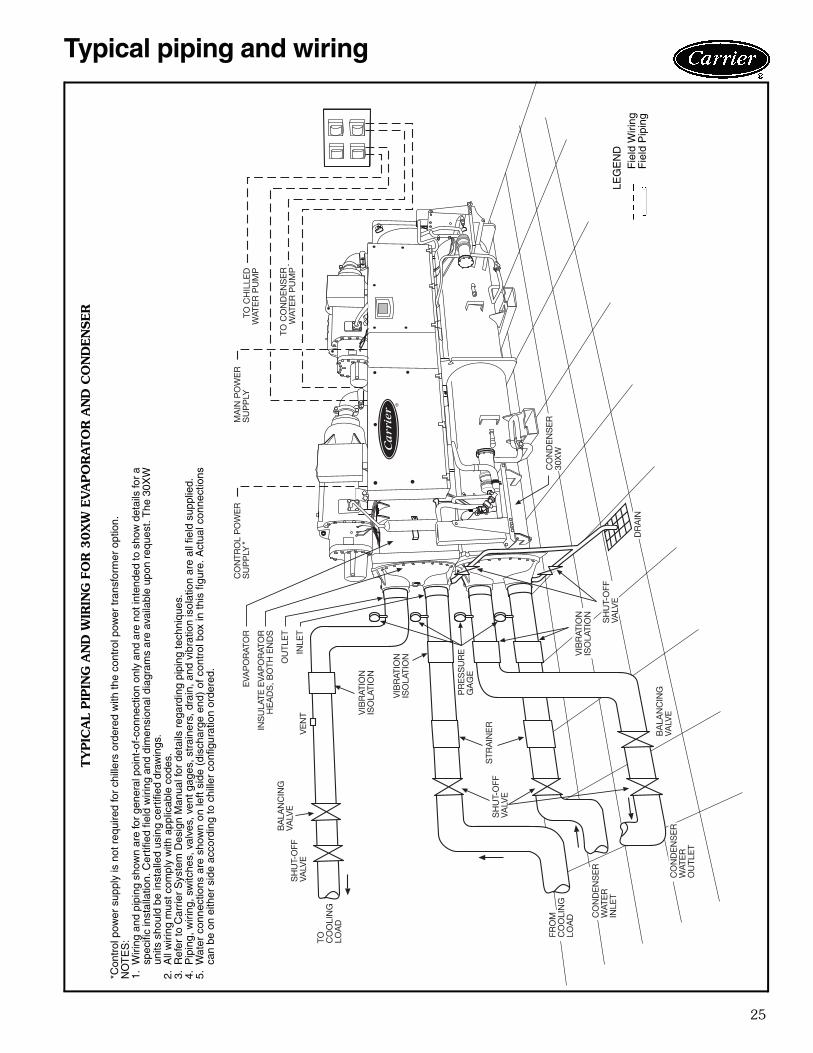
Typical piping and wiringTY
PIC
AL
PIP
ING
AN
D W
IRIN
G F
OR
30X
W E
VA
PO
RATO
R A
ND
CO
ND
EN
SER
EVA
PO
RAT
OR
SH
UT-
OFF
VALV
E
BA
LAN
CIN
GVA
LVE
TO CO
OLI
NG
LOA
D
FRO
MC
OO
LIN
GLO
AD C
ON
DE
NS
ER
WAT
ER
INLE
T
CO
ND
EN
SE
RW
ATE
RO
UTL
ET
VIB
RAT
ION
ISO
LATI
ON
VIB
RAT
ION
ISO
LATI
ON V
IBR
ATIO
NIS
OLA
TIO
N
PR
ES
SU
RE
GA
GE
SH
UT-
OFF
VALV
E
CO
ND
EN
SE
R30
XW
DR
AIN
OU
TLE
T
BA
LAN
CIN
GVA
LVE
SH
UT-
OFF
VALV
E
STR
AIN
ERIN
SU
LATE
EVA
PO
RAT
OR
HE
AD
S, B
OTH
EN
DS
VE
NT
INLE
T
CO
NTR
OL
PO
WE
RS
UP
PLY
*TO
CH
ILLE
DW
ATE
R P
UM
P
TO C
ON
DE
NS
ER
WAT
ER
PU
MP
MA
IN P
OW
ER
SU
PP
LY
*Con
trol
pow
er s
uppl
y is
not
req
uire
d fo
r ch
iller
s or
dere
d w
ith th
e co
ntro
l pow
er tr
ansf
orm
er o
ptio
n.N
OT
ES
:1.
Wiri
ng a
nd p
ipin
g sh
own
are
for
gene
ral p
oint
-of-
conn
ectio
n on
ly a
nd a
re n
ot in
tend
ed to
sho
w d
etai
ls fo
r a
spec
ific
inst
alla
tion.
Cer
tifie
d fie
ld w
iring
and
dim
ensi
onal
dia
gram
s ar
e av
aila
ble
upon
req
uest
. The
30X
Wun
its s
houl
d be
inst
alle
d us
ing
cert
ified
dra
win
gs.
2.A
ll w
iring
mus
t com
ply
with
app
licab
le c
odes
.3.
Ref
er to
Car
rier
Sys
tem
Des
ign
Man
ual f
or d
etai
ls r
egar
ding
pip
ing
tech
niqu
es.
4.P
ipin
g, w
iring
, sw
itche
s, v
alve
s, v
ent g
ages
, str
aine
rs, d
rain
, and
vib
ratio
n is
olat
ion
are
all f
ield
sup
plie
d.5.
Wat
er c
onne
ctio
ns a
re s
how
n on
left
side
(di
scha
rge
end)
of
cont
rol b
ox in
thi
s fig
ure.
Act
ual c
onne
ctio
nsca
n be
on
eith
er s
ide
acco
rdin
g to
chi
ller
conf
igur
atio
n or
dere
d.
a30-4700
LEG
EN
DF
ield
Wiri
ngF
ield
Pip
ing

26
STANDARD SINGLE INPUT POWER CONFIGURATION
LEGEND
NOTES:1. Each main power source must be supplied from a field-supplied fused
electrical service with a (factory-installed or field-installed) disconnectlocated in sight from the unit.
2. Control circuit power must be supplied from a separate source througha field-supplied disconnect. An optional control transformer may beused to provide control circuit power from the main unit power supply.
3. Maximum instantaneous current flow (ICF) during start-up is the pointin the starting sequence where the sum of the LRA for the start-upcompressor, plus the total RLA for all running compressors is at amaximum.
4. Maximum incoming wire size for each terminal block is 500 kcmil.5. Maximum allowable phase imbalance is: voltage, 2%; amps, 5%.6. Use copper conductors only.7. The MOCP is calculated as follows:
MOCP = (2.25) (largest RLA) + the sum of the other RLAs. Size thefuse one size down from the result. The RLAs are listed on thenameplate.
The recommended fuse size in amps (RFA) is calculated as follows:RFA = (1.50) (largest RLA) + the sum of the other RLAs. Size the fuseone size up from the result. The RLAs are listed on the nameplate.
30XW UNITSIZE
UNIT VOLTAGE NO. POWER SUPPLY
CONDUCTORSMCA MOCP
ICF REC FUSE SIZE
CONTROL CIRCUIT
V-Ph-HzSupplied
V-Ph-Hz MCA andMOCPMin Max WD XL
325
200-3-60 187 220 9 920.3 1200 1347.0 — 1200 115-1-60 20230-3-60 207 253 9 799.0 1000 1171.1 — 1000 115-1-60 20380-3-60 342 418 6 487.6 700 710.7 1753.7 600 115-1-60 20460-3-60 414 506 6 401.0 500 586.2 1448.2 450 115-1-60 20575-3-60 518 633 3 317.3 450 467.0 1157.0 400 115-1-60 20
325HM
200-3-60 187 220 12 1168.2 1600 1848.2 — 1600 115-1-60 20230-3-60 207 253 9 1018.4 1200 1608.6 — 1200 115-1-60 20380-3-60 342 418 6 614.5 800 973.1 2452.1 700 115-1-60 20460-3-60 414 506 6 510.8 700 805.0 2027.0 600 115-1-60 20575-3-60 518 633 6 406.8 500 642.8 1620.8 450 115-1-60 20
350
200-3-60 187 220 9 920.3 1200 1347.0 — 1200 115-1-60 20230-3-60 207 253 9 799.0 1000 1171.1 — 1000 115-1-60 20380-3-60 342 418 6 487.6 700 710.7 1753.7 600 115-1-60 20460-3-60 414 506 6 401.0 500 586.2 1448.2 450 115-1-60 20575-3-60 518 633 3 317.3 450 467.0 1157.0 400 115-1-60 20
350HM
200-3-60 187 220 12 1168.2 1600 1848.2 — 1600 115-1-60 20230-3-60 207 253 9 1018.4 1200 1608.6 — 1200 115-1-60 20380-3-60 342 418 6 614.5 800 973.1 2452.1 700 115-1-60 20460-3-60 414 506 6 510.8 700 805.0 2027.0 600 115-1-60 20575-3-60 518 633 6 406.8 500 642.8 1610.8 450 115-1-60 20
400
200-3-60 187 220 9 1041.3 1200 1400.8 — 1200 115-1-60 20230-3-60 207 253 9 902.9 1200 1217.3 — 1200 115-1-60 20380-3-60 342 418 6 545.2 700 736.3 1779.3 700 115-1-60 20460-3-60 414 506 6 452.9 600 609.3 1471.3 600 115-1-60 20575-3-60 518 633 3 366.3 500 488.8 1178.6 450 115-1-60 20
400HM
200-3-60 187 220 12 1329.8 1600 1920.0 — 1600 115-1-60 20230-3-60 207 253 12 1156.7 1600 1670.1 — 1600 115-1-60 20380-3-60 342 418 6 700.9 1000 1011.5 2490.5 800 115-1-60 20460-3-60 414 506 6 579.8 800 835.7 2057.7 700 115-1-60 20575-3-60 518 633 6 464.4 600 668.4 1646.4 600 115-1-60 20
ICF — Maximum Instantaneous Current FlowHM — Heat Machine UnitsLRA — Locked Rotor AmpsMCA — Minimum Circuit Ampacity (for wire sizing)MOCP — Maximum Overcurrent ProtectionRLA — Rated Load AmpsWD — Wye-Delta StartXL — Across-the-Line Start
Electrical data
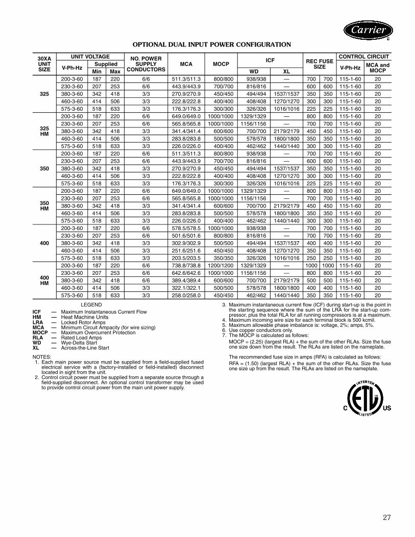
27
OPTIONAL DUAL INPUT POWER CONFIGURATION
LEGEND
NOTES:1. Each main power source must be supplied from a field-supplied fused
electrical service with a (factory-installed or field-installed) disconnectlocated in sight from the unit.
2. Control circuit power must be supplied from a separate source through afield-supplied disconnect. An optional control transformer may be usedto provide control circuit power from the main unit power supply.
3. Maximum instantaneous current flow (ICF) during start-up is the point inthe starting sequence where the sum of the LRA for the start-up com-pressor, plus the total RLA for all running compressors is at a maximum.
4. Maximum incoming wire size for each terminal block is 500 kcmil.5. Maximum allowable phase imbalance is: voltage, 2%; amps, 5%.6. Use copper conductors only.7. The MOCP is calculated as follows:
MOCP = (2.25) (largest RLA) + the sum of the other RLAs. Size the fuseone size down from the result. The RLAs are listed on the nameplate.
The recommended fuse size in amps (RFA) is calculated as follows:RFA = (1.50) (largest RLA) + the sum of the other RLAs. Size the fuseone size up from the result. The RLAs are listed on the nameplate.
30XA UNITSIZE
UNIT VOLTAGE NO. POWER SUPPLY
CONDUCTORSMCA MOCP
ICF REC FUSE SIZE
CONTROL CIRCUIT
V-Ph-HzSupplied
V-Ph-Hz MCA and MOCPMin Max WD XL
325
200-3-60 187 220 6/6 511.3/511.3 800/800 938/938 — 700 700 115-1-60 20230-3-60 207 253 6/6 443.9/443.9 700/700 816/816 — 600 600 115-1-60 20380-3-60 342 418 3/3 270.9/270.9 450/450 494/494 1537/1537 350 350 115-1-60 20460-3-60 414 506 3/3 222.8/222.8 400/400 408/408 1270/1270 300 300 115-1-60 20575-3-60 518 633 3/3 176.3/176.3 300/300 326/326 1016/1016 225 225 115-1-60 20
325HM
200-3-60 187 220 6/6 649.0/649.0 1000/1000 1329/1329 — 800 800 115-1-60 20230-3-60 207 253 6/6 565.8/565.8 1000/1000 1156/1156 — 700 700 115-1-60 20380-3-60 342 418 3/3 341.4/341.4 600/600 700/700 2179/2179 450 450 115-1-60 20460-3-60 414 506 3/3 283.8/283.8 500/500 578/578 1800/1800 350 350 115-1-60 20575-3-60 518 633 3/3 226.0/226.0 400/400 462/462 1440/1440 300 300 115-1-60 20
350
200-3-60 187 220 6/6 511.3/511.3 800/800 938/938 — 700 700 115-1-60 20230-3-60 207 253 6/6 443.9/443.9 700/700 816/816 — 600 600 115-1-60 20380-3-60 342 418 3/3 270.9/270.9 450/450 494/494 1537/1537 350 350 115-1-60 20460-3-60 414 506 3/3 222.8/222.8 400/400 408/408 1270/1270 300 300 115-1-60 20575-3-60 518 633 3/3 176.3/176.3 300/300 326/326 1016/1016 225 225 115-1-60 20
350HM
200-3-60 187 220 6/6 649.0/649.0 1000/1000 1329/1329 — 800 800 115-1-60 20230-3-60 207 253 6/6 565.8/565.8 1000/1000 1156/1156 — 700 700 115-1-60 20380-3-60 342 418 3/3 341.4/341.4 600/600 700/700 2179/2179 450 450 115-1-60 20460-3-60 414 506 3/3 283.8/283.8 500/500 578/578 1800/1800 350 350 115-1-60 20575-3-60 518 633 3/3 226.0/226.0 400/400 462/462 1440/1440 300 300 115-1-60 20
400
200-3-60 187 220 6/6 578.5/578.5 1000/1000 938/938 — 700 700 115-1-60 20230-3-60 207 253 6/6 501.6/501.6 800/800 816/816 — 700 700 115-1-60 20380-3-60 342 418 3/3 302.9/302.9 500/500 494/494 1537/1537 400 400 115-1-60 20460-3-60 414 506 3/3 251.6/251.6 450/450 408/408 1270/1270 350 350 115-1-60 20575-3-60 518 633 3/3 203.5/203.5 350/350 326/326 1016/1016 250 250 115-1-60 20
400HM
200-3-60 187 220 6/6 738.8/738.8 1200/1200 1329/1329 — 1000 1000 115-1-60 20230-3-60 207 253 6/6 642.6/642.6 1000/1000 1156/1156 — 800 800 115-1-60 20380-3-60 342 418 6/6 389.4/389.4 600/600 700/700 2179/2179 500 500 115-1-60 20460-3-60 414 506 3/3 322.1/322.1 500/500 578/578 1800/1800 400 400 115-1-60 20575-3-60 518 633 3/3 258.0/258.0 450/450 462/462 1440/1440 350 350 115-1-60 20
ICF — Maximum Instantaneous Current FlowHM — Heat Machine UnitsLRA — Locked Rotor AmpsMCA — Minimum Circuit Ampacity (for wire sizing)MOCP — Maximum Overcurrent ProtectionRLA — Rated Load AmpsWD — Wye-Delta StartXL — Across-the-Line Start
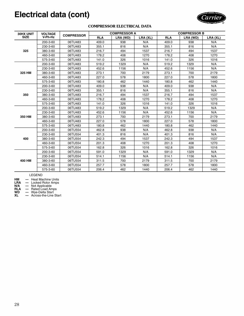
28
COMPRESSOR ELECTRICAL DATA
LEGEND
30HX UNIT SIZE
VOLTAGEV-Ph-Hz COMPRESSOR
COMPRESSOR A COMPRESSOR BRLA LRA (WD) LRA (XL) RLA LRA (WD) LRA (XL)
325
200-3-60 06TU483 409.0 938 N/A 409.0 938 N/A230-3-60 06TU483 355.1 816 N/A 355.1 816 N/A380-3-60 06TU483 216.7 494 1537 216.7 494 1537460-3-60 06TU483 178.2 408 1270 178.2 408 1270575-3-60 06TU483 141.0 326 1016 141.0 326 1016
325 HM
200-3-60 06TU483 519.2 1329 N/A 519.2 1329 N/A230-3-60 06TU483 452.6 1156 N/A 452.6 1156 N/A380-3-60 06TU483 273.1 700 2179 273.1 700 2179460-3-60 06TU483 227.0 578 1800 227.0 578 1800575-3-60 06TU483 180.8 462 1440 180.8 462 1440
350
200-3-60 06TU483 409.0 938 N/A 409.0 938 N/A230-3-60 06TU483 355.1 816 N/A 355.1 816 N/A380-3-60 06TU483 216.7 494 1537 216.7 494 1537460-3-60 06TU483 178.2 408 1270 178.2 408 1270575-3-60 06TU483 141.0 326 1016 141.0 326 1016
350 HM
200-3-60 06TU483 519.2 1329 N/A 519.2 1329 N/A230-3-60 06TU483 452.6 1156 N/A 452.6 1156 N/A380-3-60 06TU483 273.1 700 2179 273.1 700 2179460-3-60 06TU483 227.0 578 1800 227.0 578 1800575-3-60 06TU483 180.8 462 1440 180.8 462 1440
400
200-3-60 06TU554 462.8 938 N/A 462.8 938 N/A230-3-60 06TU554 401.3 816 N/A 401.3 816 N/A380-3-60 06TU554 242.3 494 1537 242.3 494 1537460-3-60 06TU554 201.3 408 1270 201.3 408 1270575-3-60 06TU554 162.8 326 1016 162.8 326 1016
400 HM
200-3-60 06TU554 591.0 1329 N/A 591.0 1329 N/A230-3-60 06TU554 514.1 1156 N/A 514.1 1156 N/A380-3-60 06TU554 311.5 700 2179 311.5 700 2179460-3-60 06TU554 257.7 578 1800 257.7 578 1800575-3-60 06TU554 206.4 462 1440 206.4 462 1440
HM — Heat Machine UnitsLRA — Locked Rotor AmpsN/A — Not ApplicableRLA — Rated Load AmpsWD — Wye-Delta StartXL — Across-the-Line Start
Electrical data (cont)

29
Water-Cooled ChillerHVAC Guide SpecificationsSize Range: 325 to 400 Nominal Tons
(1133 to 1354 kW)Carrier Model Number: 30XWPart 1 — General1.01 SYSTEM DESCRIPTION
Microprocessor controlled water-cooled liquid chillerutilizing screw compressors and electronic expan-sion valves.
1.02 QUALITY ASSURANCEA. Unit shall be rated in accordance with AHRI Stan-
dard 550/590 (U.S.A.), latest edition. B. Unit construction shall comply with ASHRAE 15
Safety Code, NEC, and ASME applicable codes(U.S.A. codes).
C. Unit shall be manufactured in a facility registered toISO 9001:2000 Manufacturing Quality Standard.
D. 200-v, 230-v, 460-v, 575-v, 60 Hz units shall beconstructed in accordance with UL or UL Canadastandards and shall be tested and listed by ETL orETL, Canada, as conforming to those standards.Units shall carry the ETL and ETL, Canada, labels.
1.03 DELIVERY, STORAGE, AND HANDLINGA. Unit controls shall be capable of withstanding 150 F
(65.5 C) storage temperatures in the controlcompartment.
B. Chiller and starter should be stored indoors, pro-tected from construction dirt and moisture. Aninspection should be conducted under shippingtarps, bags, or crates to be sure water has not col-lected during transit. Protective shipping coversshould be kept in place until machine is ready forinstallation. The inside of the protective covershould meet the following criteria:
1. Temperature is between 40 F (4.4 C) and120 F (48.9 C).
2. Relative humidity is between 10% and 80%(non-condensing).
Part 2 — Products2.01 EQUIPMENT
A. General:Factory assembled, single-piece, water-cooled liquidchiller with dual (2) independent refrigerant circuits.Contained within the unit cabinet shall be all factorywiring, piping, controls, refrigerant charge (HFC-134a) and special features required prior to fieldstart-up.
B. Compressors:1. Semi-hermetic twin-screw compressors with
internal muffler and check valve.2. Each compressor shall be equipped with a dis-
charge shutoff valve.
C. Evaporator:1. Shall be tested and stamped in accordance
with ASME Code (U.S.A.) for a refrigerantworking-side pressure of 220 psig (1408 kPa).Water-side pressure rating shall be 150 psig(1034 kPa). In Canada, maximum water-sidepressure shall be 250 psig (1725 kPa), per theCanadian National Registry.
2. Shall be mechanically cleanable shell-and-tubetype with removable heads.
3. Tubes shall be internally enhanced, seamless-copper type, and shall be rolled into tubesheets.
4. Shall be equipped with victaulic fluidconnections.
5. Shell shall be insulated with 3/4-in. (19-mm)closed-cell, polyvinyl chloride foam with a maxi-mum K factor of 0.28. Heads may require fieldinsulation.
6. Shall have a evaporator drain and vent.7. Design shall incorporate 2 independent refrig-
erant circuits.8. Shall include isolation valves to allow isolation
of the refrigerant charge in either the evapora-tor or the condenser.
9. Shall be equipped with factory-installed thermaldispersion chilled fluid flow switch.
D. Condenser:1. Shall be tested and stamped in accordance
with ASME code (U.S.A.) for a refrigerantworking-side pressure of 220 psig (1408 kPa).Water-side pressure rating shall be 150 psig(1034 kPa). In Canada, maximum water-sidepressure shall be 250 psig (1725 kPa), per theCanadian National Registry.
2. Shall be mechanically cleanable shell-and-tubetype with removable heads.
3. Tubes shall be internally enhanced, seamless-copper type, and shall be rolled into tubesheets.
4. Shall be equipped with victaulic waterconnections.
5. Design shall incorporate 2 independent refrig-erant circuits.
E. Heat Machines:1. Condenser shall be tested and stamped in
accordance with ASME Code (U.S.A.) for arefrigerant working-side pressure of 300 psig(2068 kPa).
2. Design shall incorporate 2 independent refrig-erant circuits.
3. Heat machine condensers shall include factory-installed thermal insulation on the condenser,condenser flow switch and leaving watertemperature sensor. Heat machine unitsrequire field-installed thermal insulation on the
Guide specifications

30
compressor discharge piping and waterboxheads because of high temperature.
F. Refrigeration Components:Refrigerant circuit components shall include oil sep-arator, high and low side pressure relief devices, dis-charge and liquid line shutoff valves, filter drier,moisture indicating sight glass, expansion valve,refrigerant economizer (unit sizes 350, 400), andcomplete charge of compressor oil. The units shallhave a complete operating charge of refrigerantHFC-134a.
G. Controls:1. Unit controls shall include the following mini-
mum components: a. Microprocessor with non-volatile memory.
Battery backup system shall not be accepted.b. Separate terminal block for power and
controls.c. Separate 115-v power supply to serve all
controllers, relays, and control components.d. ON/OFF control switch.e. Replaceable solid-state controllers.f. Pressure sensors installed to measure
suction, oil, economizer, and dischargepressure. Thermistors installed to measureevaporator entering and leaving fluidtemperatures.
2. Unit controls shall include the followingfunctions:a. Automatic circuit lead/lag.b. Capacity control based on leaving chilled
fluid temperature and compensated by rateof change of return-fluid temperature withtemperature set point accuracy to 0.1° F(0.05° C).
c. Limiting the chilled fluid temperaturepulldown rate at start-up to an adjustablerange of 0.2° F to 2° F (0.1 to 1.1° C) perminute to prevent excessive demand spikesat start-up.
d. Seven-day time schedule.e. Leaving chilled fluid temperature reset from
return fluid and outside air temperature.f. Chilled water and condenser water pump
start/stop control.g. Chiller control for parallel chiller applications
without addition of hardware modules andcontrol panels (requires thermistors).
h. Timed maintenance scheduling to signalmaintenance activities for strainermaintenance and user-defined maintenanceactivities.
i. Single step demand limit control activated byremote contact closure.
H. Safeties:Unit shall be equipped with thermistors and all nec-essary components in conjunction with the controlsystem to provide the unit with the followingprotections:
1. Loss of refrigerant charge.2. Reverse rotation.3. Low chilled fluid temperature.4. Motor overtemperature.5. High pressure.6. Electrical overload.7. Loss of phase.8. Loss of chilled water flow
I. Diagnostics:1. The control panel shall include, as standard, a
display:a. Touch screen display consisting of ¼ VGA
LCD (liquid crystal display) with adjustablecontrast and backlighting.
b. Display shall allow a user to navigatethrough menus, select desired options andmodify data.
2. Features of the display shall include:a. Display shall be customizable and allow up to
72 data points.b. Display shall support both local equipment
or network made for remote mount.c. Display shall allow access to configuration,
maintenance, service, set point, time sched-ules, alarm history and status data.
d. Display shall have one button for chiller on/off.
e. Display shall include three levels of passwordprotection against unauthorized access toconfiguration and maintenance informa-tion, and display set up parameters.
f. Display shall allow for easy connection of aportable hand held technician tool to accessinformation and upload and/or downloadchiller settings.
g. Display shall be compatible with the CarrierComfort Network® (CCN) system and pro-vide network alarm acknowledgement orindication and provide capability to fullymonitor and control chiller.
h. Display alarms and parameters shall becapable of being displayed in full text.
i. Display shall be capable of displaying the last50 alarms and will store a snapshot of aminimum of 20 status data parameters foreach alarm.
j. Compressor run hours.k. Compressor number of starts.l. Compressor current.
Guide specifications (cont)

31
m. Time of day:1) Display module, in conjunction with the
microprocessor, must also be capable ofdisplaying the output (results) of a ser-vice test. Service test shall verify opera-tion of every switch, thermistor, andcompressor before chiller is started.
2) Diagnostics shall include the ability toreview a list of the 30 most recentalarms with clear language descriptionsof the alarm event. Display of alarmcodes without the ability for clear lan-guage descriptions shall be prohibited.
3) An alarm history buffer shall allow theuser to store no less than 30 alarmevents with clear language descriptions,time and date stamp event entry.
4) The chiller controller shall include multi-ple connection ports for communicatingwith the local equipment network, theCarrier Comfort Network (CCN) sys-tem and the ability to access all chillercontrol functions from any point on thechiller.
5) The control system shall allow softwareupgrade without the need for new hard-ware modules.
J. Operating Characteristics:Unit shall be capable of starting up with 95 F (35 C)entering fluid temperature to the evaporator.
K. Electrical Requirements:1. Unit primary electrical power supply shall enter
the unit at a single location.2. Unit shall operate on 3-phase power at the volt-
age shown in the equipment schedule.3. Control voltage shall be 115-v (60 Hz), single-
phase, separate power supply.L. Special Features:
Certain standard features are not applicable whenthe features designated by * are specified. For assis-tance in amending the specifications, contact yourlocal Carrier Sales office.
* 1. Wye-Delta Starter:Unit shall have a factory-installed, wye-deltastarter to minimize electrical inrush current.
2. Vibration Isolation:Unit shall be supplied with rubber-in-shearvibration isolators for field installation.
3. Control Power Transformer:Unit shall be supplied with a factory-installedcontrols transformer that will supply control cir-cuit power from the main unit power supply.
4. Temperature Reset Sensor:Unit shall reset leaving chilled fluid temperaturebased on outdoor ambient temperature orspace temperature when this sensor is installed.
* 5. Minimum Load Control:Unit shall be equipped with factory-installed,microprocessor-controlled, minimum load con-trol that shall permit unit operation down to10% of full capacity.
6. One-Pass Evaporator:Factory-installed option shall reduce pressuredrop for high flow applications.
7. Three-Pass Evaporator:Factory-installed option shall enhance perfor-mance for low flow applications.
8. Energy Management Module:A factory or field installed module shall providethe following energy management capabilities:4 to 20 mA signals for leaving fluid temperaturereset, cooling set point reset or demand limitcontrol; 2-point demand limit control (from 0 to100%) activated by a remote contact closure;and discrete input for "Ice Done" indication forice storage system interface.
9. BACnet™ Translator Control:Unit shall be supplied with field-installed inter-face between the chiller and a BACnet LocalArea Network (LAN, i.e., MS/TP EIA-485).
10. LON Translator Control:Unit shall be supplied with field-installed inter-face between the chiller and a Local OperatingNetwork (LON, i.e., LonWorks® FT-10AANSI/EIA-709.1).
11. Navigator™ Hand Held Portable Display:a. Portable hand held display module with a
minimum of 4 lines and 20 characters perline, or clear English, Spanish, Portugueseor French language.
b. Display menus shall provide clear languagedescriptions of all menu items, operatingmodes, configuration points and alarm diag-nostics. Reference to factory codes shall notbe accepted.
c. RJ-14 connection plug shall allow displaymodule to be connected to factory-installedreceptacle.
d. Industrial grade coiled extension cord shallallow the display module to be movedaround the chiller.
e. Magnets shall hold the display module toany sheet metal panel to allow hands-freeoperation.
f. Display module shall have NEMA 4xhousing.
g. Display shall have back light and contrastadjustment for easy viewing in bright sun-light or night conditions.
h. Raised surface buttons with positive tactileresponse.

Manufacturer reserves the right to discontinue, or change at any time, specifications or designs without notice and without incurring obligations. Pg 32 Catalog No. 04-52300015-01 Printed in U.S.A. Form 30XW-2PD
Replaces: 30XW-1PD
Carrier Corporation • Syracuse, New York 13221 6-09
Section 9Tab 9a
12. Compressor Suction Service Valve:Standard refrigerant discharge isolation andliquid valves enable service personnel to storethe refrigerant charge in the evaporator orcondenser during servicing. This factory-installed option allows for further isolation ofthe compressor from the evaporator vessel.
13. GFI Convenience Outlet:Shall be factory or field-installed and mountedwith easily accessible 115-v female receptacle.Shall include 4 amp GFI receptacle.
14. 300 psig (2068 kPa) Evaporator OperatingPressure:This option shall provide for water-side pres-sure operation up to 300 psig (2068 kPa).
15. 300 psig (2068 kPa) Condenser OperatingPressure:This option shall provide for water-side pres-sure operation up to 300 psig (2068 kPa).
16. Marine Waterboxes:Marine waterboxes shall provide water pipingconnections extending from the side of thewaterbox (as opposed to extending from theend of the waterbox). This option also includesa removable bolt on waterbox cover allowingaccess to the heat exchanger tubes withoutbreaking the existing field piping. This optionis available for both the evaporator andcondenser.
17. Flanged Connection:The flanged connection option shall providean ANSI flange on the end of the chiller waterpiping for connection to a customer suppliedmating flange in the field piping. This optionis available for both the evaporator andcondenser.
18. One-Pass Condenser:This option shall provide a lower pressuredrop through the condenser for applicationswith low delta T (temperature) or high flow orwhere the condensers are piped in a series.The one-pass condenser option is only avail-able with flanged connections and with a dis-charge end leaving water connection.
19. Dual Point Power:The dual point power option shall provide ameans for connecting two sources of power todual compressor chillers. One source of poweris wired to operate the compressor on the Acircuit and one source of power is wired tooperate the compressor on the B circuit of thechiller.
20. Non-Fused Disconnect:This option shall provide a no load, lockable,through the door handle disconnect for unitpower on the chiller. On dual point power,one disconnect is provided for each of the twomain power supplies. This disconnect doesnot remove the control circuit from powersupply.
21. Control Transformer:The control transformer shall be sized to sup-ply the needs of the control circuit from themain power supply.
22. Nitrogen Charge:A nitrogen charge option is available to pro-vide a 15 lb (6.8 kg) charge of nitrogeninstead of a full factory charge of R-134arefrigerant to keep the chiller refrigerant cir-cuit dry during shipment. This option is rec-ommended for applications where the unit willbe disassembled prior to installation. Unitsshipped with a nitrogen charge will receive anelectrical continuity test at the factory prior toshipment.
23. Crate for Shipment:This option is recommended for exportorders. The chiller will be bagged prior tobeing placed in a wooden crate.
24. Remote Enhanced Display:This option is a remotely mounted indoor40-character per line, 16-line display panel forunit monitoring and diagnostics.
25. Vibration Springs:A set of non-siesmic spring isolators can beprovided for installation at the jobsite.
Guide specifications (cont)