Embed Size (px)
Citation preview
LEE B004-07-09
1
2
3
4
0
ELE
CT
RO
DE
DIA
ME
TE
R (M
M)
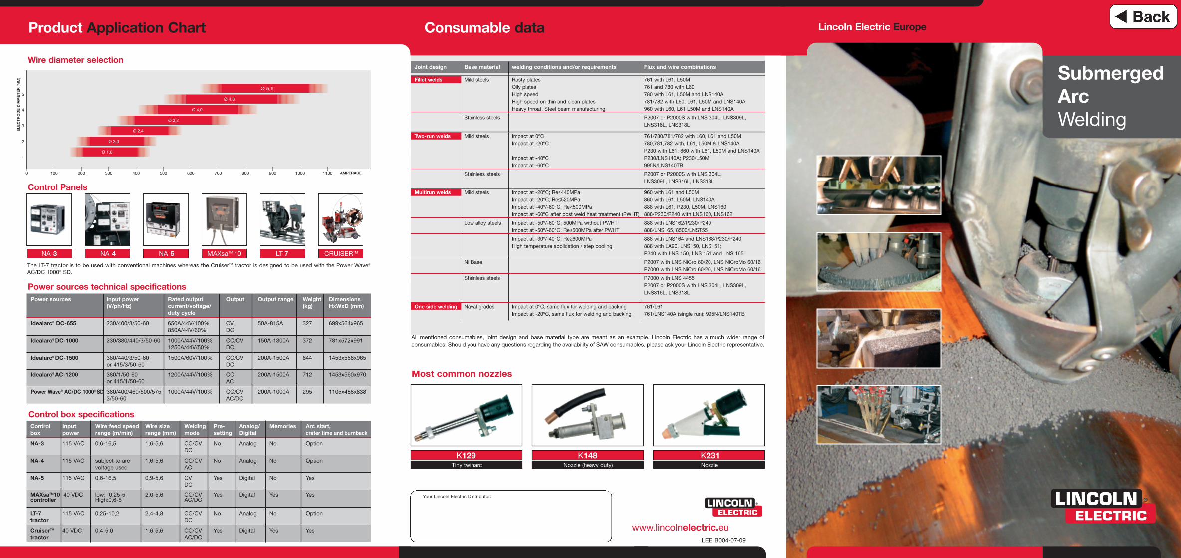
AMPERAGE100 200 300 400 500 600 700 800 900 1000 1100
Ø 1,6
Ø 2,0
Ø 2,4
Ø 3,2
Ø 4,0
Ø 4,8
Ø 5,65
Lincoln Electric Europe
SubmergedArcWelding
Consumable dataProduct Application Chart
www.lincolnelectric.eu
Power sources technical specifications
Control Panels
Wire diameter selection
Your Lincoln Electric Distributor:
Control Input Wire feed speed Wire size Welding Pre- Analog/ Memories Arc start, box power range (m/min) range (mm) mode setting Digital crater time and burnback
NA-3 115 VAC 0,6-16,5 1,6-5,6 CC/CV No Analog No OptionDC
NA-4 115 VAC subject to arc 1,6-5,6 CC/CV No Analog No Optionvoltage used AC
NA-5 115 VAC 0,6-16,5 0,9-5,6 CV Yes Digital No YesDC
MAXsaTM10 40 VDC low: 0,25-5 2,0-5,6 CC/CV Yes Digital Yes Yescontroller High:0,6-8 AC/DC
LT-7 115 VAC 0,25-10,2 2,4-4,8 CC/CV No Analog No Optiontractor DC
CruiserTM 40 VDC 0,4-5,0 1,6-5,6 CC/CV Yes Digital Yes Yestractor AC/DC
Power sources Input power Rated output Output Output range Weight Dimensions (V/ph/Hz) current/voltage/ (kg) HxWxD (mm)
duty cycle
Idealarc® DC-655 230/400/3/50-60 650A/44V/100% CV 50A-815A 327 699x564x965850A/44V/60% DC
Idealarc® DC-1000 230/380/440/3/50-60 1000A/44V/100% CC/CV 150A-1300A 372 781x572x9911250A/44V/50% DC
Idealarc® DC-1500 380/440/3/50-60 1500A/60V/100% CC/CV 200A-1500A 644 1453x566x965or 415/3/50-60 DC
Idealarc® AC-1200 380/1/50-60 1200A/44V/100% CC 200A-1500A 712 1453x560x970or 415/1/50-60 AC
Power Wave® AC/DC 1000® SD 380/400/460/500/575 1000A/44V/100% CC/CV 200A-1000A 295 1105x488x8383/50-60 AC/DC
The LT-7 tractor is to be used with conventional machines whereas the CruiserTM tractor is designed to be used with the Power Wave®
AC/DC 1000® SD.
K129 K148 K231Tiny twinarc Nozzle (heavy duty) Nozzle
Joint design Base material welding conditions and/or requirements Flux and wire combinations
Fillet welds Mild steels Rusty plates 761 with L61, L50MOily plates 761 and 780 with L60High speed 780 with L61, L50M and LNS140AHigh speed on thin and clean plates 781/782 with L60, L61, L50M and LNS140AHeavy throat, Steel beam manufacturing 960 with L60, L61 L50M and LNS140A
Stainless steels P2007 or P2000S with LNS 304L, LNS309L, LNS316L, LNS318L
Two-run welds Mild steels Impact at 0ºC 761/780/781/782 with L60, L61 and L50MImpact at -20ºC 780,781,782 with, L61, L50M & LNS140A
P230 with L61; 860 with L61, L50M and LNS140A Impact at -40ºC P230/LNS140A; P230/L50MImpact at -60ºC 995N/LNS140TB
Stainless steels P2007 or P2000S with LNS 304L, LNS309L, LNS316L, LNS318L
Multirun welds Mild steels Impact at -20ºC; Re≤440MPa 960 with L61 and L50MImpact at -20ºC; Re≤520MPa 860 with L61, L50M, LNS140AImpact at -40º/-60°C; Re<500MPa 888 with L61, P230, L50M, LNS160Impact at -60ºC after post weld heat treatment (PWHT) 888/P230/P240 with LNS160, LNS162
Low alloy steels Impact at -50º/-60°C; 500MPa without PWHT 888 with LNS162/P230/P240Impact at -50º/-60°C; Re≥500MPa after PWHT 888/LNS165, 8500/LNST55
Impact at -30º/-40°C; Re≥600MPa 888 with LNS164 and LNS168/P230/P240High temperature application / step cooling 888 with LA90, LNS150, LNS151;
P240 with LNS 150, LNS 151 and LNS 165
Ni Base P2007 with LNS NiCro 60/20, LNS NiCroMo 60/16P7000 with LNS NiCro 60/20, LNS NiCroMo 60/16
Stainless steels P7000 with LNS 4455P2007 or P2000S with LNS 304L, LNS309L, LNS316L, LNS318L
One side welding Naval grades Impact at 0ºC, same flux for welding and backing 761/L61Impact at -20ºC, same flux for welding and backing 761/LNS140A (single run); 995N/LNS140TB
All mentioned consumables, joint design and base material type are meant as an example. Lincoln Electric has a much wider range ofconsumables. Should you have any questions regarding the availability of SAW consumables, please ask your Lincoln Electric representative.
Most common nozzles
NA-3 NA-4 NA-5 MAXsaTM 10 CRUISERTMLT-7
Control box specifications
SAW Process Applications The new Sub Arc Power Source Generation
Segment and applications• Light & heavy industry with non alloyed products• Pressure vessels with low alloyed products• Pipemills all grades• Offshore with low alloyed products• Process industry with low & high alloyed products
Materials• Carbon steel• Stainless steel• Nickel based alloys
Equipment requirements• Robustness• Outstanding welding performance• High duty cycle• Versatility of welding mode• Modularity
SAW diversity
The Lincoln Solution
Equipment• Excellent arc characteristics with:
3 CV and CC modes for DC-655, DC-1000 and DC-15003 DC+/DC- switch button for DC-655, DC-1000 and DC-15003 3 output studs with overlapping ranges for AC-12003 Possibility to use DC-655 and DC-1000 with GMAW,
SMAW and FCAW processes
• 3 phase input for DC-655, DC-1000, DC-1500
• 1 phase input for AC-1200
• Rugged design for impact resistance and toughness
• IP 23 classified
• 3-year warranty on parts and labour
DC-655
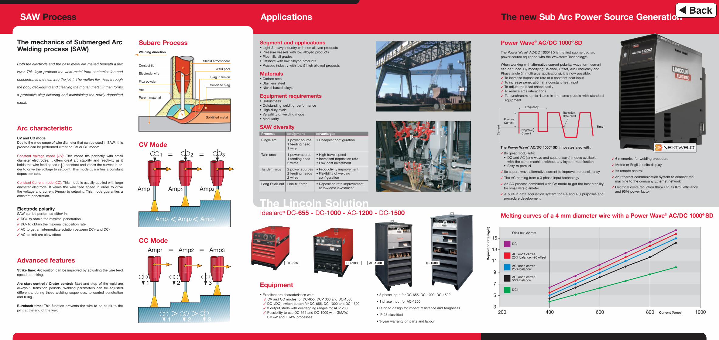
Power Wave® AC/DC 1000® SD
The Power Wave® AC/DC 1000® SD is the first submerged arcpower source equipped with the Waveform Technology®.
When working with alternative current polarity, wave form currentcan be tuned. By modifying Balance, Offset, Arc Frequency andPhase angle (in multi arcs applications), it is now possible:3 To increase deposition rate at a constant heat input3 To increase penetration at a constant heat input3 To adjust the bead shape easily3 To reduce arcs interactions3 To synchronize up to 4 arcs in the same puddle with standard
equipment
Melting curves of a 4 mm diameter wire with a Power Wave® AC/DC 1000® SD
DC-1000 AC-1200 DC-1500
Process equipment advantages
Single arc 1 power source • Cheapest configuration1 feeding head1 wire
Twin arcs 1 power source • High travel speed1 feeding head • Increased deposition rate2 wires • Low cost investment
Tandem arcs 2 power sources • Productivity improvement2 feeding heads • Flexibility of welding 2 wires configuration
Long Stick-out Linc-fill torch • Deposition rate improvement at low cost investment
The Power Wave® AC/DC 1000® SD innovates also with:
3 Its great modularity:• DC and AC (sine wave and square wave) modes available
with the same machine without any layout modification• Easy to parallel
3 Its square wave alternative current to improve arc consistency
3 The AC coming from a 3 phase input technology
3 An AC process combined with CV mode to get the best stabilityfor small wire diameter
3 A built-in data acquisition system for QA and QC purposes andprocedure development
3 6 memories for welding procedure
3 Metric or English units display
3 Its remote control
3 An Ethernet communication system to connect themachine to the company Ethernet network
3 Electrical costs reduction thanks to its 87% efficiencyand 95% power factor
CC Mode
CV Mode
Subarc Process
Frequency
NegativeCurrent
PositiveCurrent
TransitionRate dI/dT
Cur
rent Time
Contact tip
Welding direction
Electrode wire
Flux powder
Arc
Parent material
Shield atmosphere
Weld pool
Slag in fusion
Solidified slag
Solidified metal
= =
Amp1 = Amp2 = Amp3
The mechanics of Submerged ArcWelding process (SAW)
Both the electrode and the base metal are melted beneath a flux
layer. This layer protects the weld metal from contamination and
concentrates the heat into the joint. The molten flux rises through
the pool, deoxidising and cleaning the molten metal. It then forms
a protective slag covering and maintaining the newly deposited
metal.
Arc characteristicCV and CC modeDue to the wide range of wire diameter that can be used in SAW, thisprocess can be performed either on CV or CC mode:
Constant Voltage mode (CV): This mode fits perfectly with smalldiameter electrodes. It offers great arc stability and reactivity as itholds the wire feed speed ( ) constant and varies the current in or-der to drive the voltage to setpoint. This mode guaranties a constantdeposition rate.
Constant Current mode (CC): This mode is usually applied with largediameter electrode. It varies the wire feed speed in order to drive the voltage and current (Amps) to setpoint. This mode guaranties aconstant penetration.
Electrode polaritySAW can be performed either in:
3 DC+ to obtain the maximal penetration
3 DC- to obtain the maximal deposition rate
3 AC to get an intermediate solution between DC+ and DC-
3 AC to limit arc blow effect
Advanced featuresStrike time: Arc ignition can be improved by adjusting the wire feedspeed at striking.
Arc start control / Crater control: Start and stop of the weld arealways 2 transition periods. Welding parameters can be adjusted differently, during these welding sequences, to control penetrationand filling.
Burnback time: This function prevents the wire to be stuck to thejoint at the end of the weld.
1 2 3
Idealarc® DC-655 - DC-1000 - AC-1200 - DC-1500