Embed Size (px)
Citation preview

Copyright 2002 Carrier Corporation Form 30GXN-C1PD
The long-standing Engineering sym-bol for efficiency, η, is now Carrier'ssymbol for air-cooled chiller efficiency.The standard efficiency ECOLOGICand high efficiency ECOLOGIC η TM
30GXN,R air-cooled chillers are de-signed from the ground up to meet theneeds of today and tomorrow.
Features/BenefitsEasy installationThe 30GXN,R unit has a compact design that is up to 50% smaller than earlier air-cooled chillers. The compact footprint can yield substantial installation savings by requiring less structural steel, concrete, security fencing or architectural screen-ing. The 30GXN,R unit is delivered as a complete package for easy installation.
A quick start-up is assured onceinstallation is complete, since each 30GXN,R unit is manufactured at anISO 9001:2000 listed manufacturingfacility to ensure quality. In addition, all units are factory run tested under full load to provide reliable start-up.
Easy to live withThe 30GXN,R units have a quiet, low-vibration design featuring rotary screw compression and “aero-acoustic” fans that reduce sound levels and improve sound quality. Lower sound levels help avoid the need for costly sound barriers that may be needed with other screw compressor chillers. The 30GXN,R con-trols are fully automatic. The leaving-fluid temperature is directly controlled, and the entering-fluid temperature is continu-ously monitored to detect load and flow changes. This combination (an exclusive ComfortLink™ controls advantage) pro-vides the most precise temperature con-trol available. In addition, the 30GXN,R units can handle both quick and slow-loading applications. The 30GXN,R units use chlorine-free HFC-134a refrig-erant to help protect the Earth’s ozone layer and your investment. From a
30GXN,GXR080-528High Efficiency
ECOLOGIC™ and ECOLOGIC η™Air-Cooled Chillers
with ComfortLink™ Controls50 Hz
80 to 525 Nominal Tons (267 to 1750 kW)
ProductData
ECOLOGIC and ECOLOGIC η

2
service standpoint, the 30GXN,R units offer the following features:• Use of HFC-134a refrigerant, a single
compound refrigerant that is easy to handle, readily available, and not sub-ject to phase out
• Mechanically cleanable cooler• Twin screw compressors require little
routine service or maintenance• Easy viewing of suction and discharge
pressures and temperatures using either standard or accessory display module
Rotary screw compressionCarrier chillers utilize the Carrier Carlyle 06N Geared Twin screw compres-sor. Built in a state-of-the-art facility inSyracuse, New York (U.S.A.), these third generation rotary-screw compressors are designed, tested, and built to the highstandards that are expected from the world leader in comfort cooling.
Since operating pressures with HFC-134a are about 30% lower than conventional systems using HCFC-22, internal rotor blowby is reduced, thereby increasing compression efficiency and re-ducing chiller plant size. And, since the Carlyle 06N compressor is liquid cooled, it has a low internal pressure drop that makes it ideally suited for use withHFC-134a. All 06N compressors used in 30GXN,R chillers are equipped with the advanced ComfortLink CompressorProtection Module (CPM). The CPMprotects compressors from phase-loss, reverse rotation, over or under current conditions and ground current failures that can lead to motor burnout, system contamination and costly systemclean-outs.
ComfortLink controlComfortLink is your link to a world of simple and easy to use air-cooled chillers that offer outstanding performance and value. The 30GXN,R liquid chillers em-ploy more than the latest advancedmicroprocessor controls, they utilize an expandable platform that grows as your needs change. From stand-alone opera-tion to remotely monitored and operated multi-chiller plants, ComfortLink con-trols can keep you plugged in.
ComfortLink controls are fully com-municating, and are cable ready for con-nection to a Carrier Comfort Network (CCN). Occupancy scheduling, tempera-ture and pressure readouts, and the ComfortLink handheld Navigator clear language display compliment thestandard features, linking you to a world of carefree comfort. The 30GXN,R chill-ers are built on the legendary perfor-mance of the Carrier model 30G Flotronic™ chiller and share many of the same time-proven features and technolo-gies providing easy operation, quick
installation and start-ups that save you money!
Superior temperature control equals potential for greater productivityWhether in the classroom, on the pro-duction floor, or in the office,ComfortLink controls can help you to adapt to changing weather and business conditions. Accurate temperature control provided by the Carrier ComfortLink system helps to maintain higher levels of indoor air quality, thermal comfort, and productive space.
While many air-cooled chillers use only leaving fluid temperature control, the 30GXN,R chillers utilize leaving fluid tem-perature control with a standardentering fluid temperature compensation. This Carrier exclusive provides smart control and intelligent machine capacity staging to within +.5 F (.4 C) of set point. Unlike many chillers, Carrier model 30GXN,R chillers do not require constant fluid flow. The ability to operate with vari-able flow also allows building owners to realize even greater overall system energy savings in the chilled water pumping sys-tem, and not just at the chiller.
Energy management made easyWhile 30GXN,R chillers have manystandard features such as network com-munications capability and temperature reset based on return fluid temperature, they can also expand as needs change. Supply temperature reset based on out-side air or space temperature is as easy as adding a thermistor. The Energy Man-agement option can allow you to takeadvantage of changing utility rate struc-tures with easy to use load shedding,demand limiting and temperature reset
capabilities. Reset triggered via 4 to20 mA signal makes integrating from an existing building management system simple.
The 30GXN,R comes standard with the ComfortLink Navigator display, available with optional remote service connection port. The Navigator displays information in a clear language format. The 4-line 20-character display can be plugged into the unit at either the control panel or at the remote service port. This allows the service technician to operate the unit from where the maintenance or service work is being performed, mini-mizing downtime and ensuring the sys-tem is ready for operation in the shortest amount of time.
Optional Low AmbientProtection to 0° F (–17.7 C)on all units Factory-installed cooler head heaters and liquid line solenoid valves combined with a pump down cycle provide cooler ambi-ent protection to 0° F (–17.7 C).
Features• Simple and easy to use ComfortLink
communicating controls.• Wide operating envelope from –20 to
125 F (28 to 52 C).• Accurate temperature control with
return fluid compensation.• Built-in dual chiller control, reset from
return.• Superior full and part-load efficiency.• Precise multiple-step capacity.• Low noise operation.• Dual independent refrigerant circuits.• Full load factory run tested.• Wide range of sizes available from
stock.• Compact size.
Table of contentsPage
Features/Benefits . . . . . . . . . . . . . . . . . . . . . . . . . . . . . . . . . . . . . . . . . . . . 1-3Model Number Nomenclature . . . . . . . . . . . . . . . . . . . . . . . . . . . . . . . . . . . . . 4Physical Data . . . . . . . . . . . . . . . . . . . . . . . . . . . . . . . . . . . . . . . . . . . . . . . 5-8Options and Accessories . . . . . . . . . . . . . . . . . . . . . . . . . . . . . . . . . . . . . . 9-11Dimensions . . . . . . . . . . . . . . . . . . . . . . . . . . . . . . . . . . . . . . . . . . . . . . 12-45
Detail Drawings . . . . . . . . . . . . . . . . . . . . . . . . . . . . . . . . . . . . . . . . . . 12-39Mounting Weights . . . . . . . . . . . . . . . . . . . . . . . . . . . . . . . . . . . . . . . . 40-45
Selection Procedure . . . . . . . . . . . . . . . . . . . . . . . . . . . . . . . . . . . . . . . . . . . 46Performance Data . . . . . . . . . . . . . . . . . . . . . . . . . . . . . . . . . . . . . . . . . 47-59Typical Piping and Wiring . . . . . . . . . . . . . . . . . . . . . . . . . . . . . . . . . . . . 60,61Electrical Data . . . . . . . . . . . . . . . . . . . . . . . . . . . . . . . . . . . . . . . . . . . . . 62-68Controls . . . . . . . . . . . . . . . . . . . . . . . . . . . . . . . . . . . . . . . . . . . . . . . . . . . 69Typical Control Wiring Schematic . . . . . . . . . . . . . . . . . . . . . . . . . . . . . . . . . 70Application Data . . . . . . . . . . . . . . . . . . . . . . . . . . . . . . . . . . . . . . . . . . . 71-74Guide Specifications. . . . . . . . . . . . . . . . . . . . . . . . . . . . . . . . . . . . . . . . . 75-78
3
Features/Benefits (cont)
Run StatusService TestTemperaturesPressures
SetpointsInputs
OutputsConfigurationTime Clock
Operating ModesAlarms
ENTER
E S C
M O D EAlarm Status
Leaving Water Temperature4 4 . 0 ° F
N A V I G A T O R ™
C o m f o r t L i n k
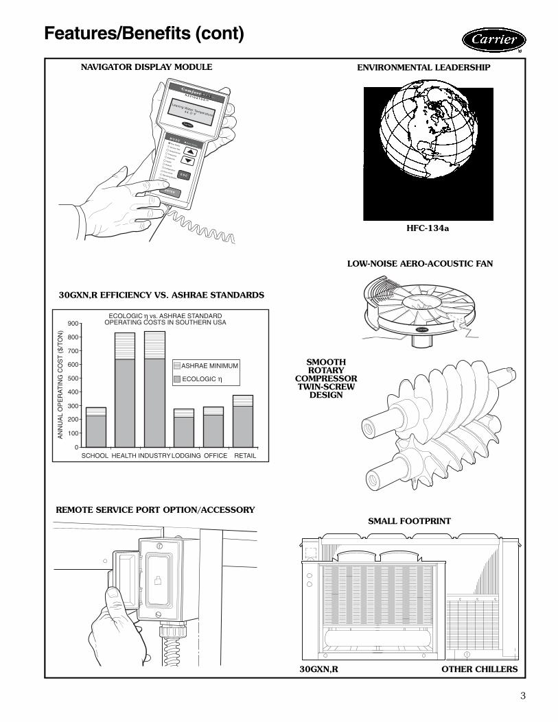
ECOLOGIC vs. ASHRAE STANDARDOPERATING COSTS IN SOUTHERN USA
SCHOOL HEALTH INDUSTRY RETAILOFFICELODGING
AN
NU
AL
OP
ER
AT
ING
CO
ST
($/T
ON
)
900
800
700
600
500
400
300
200
100
0
ASHRAE MINIMUM
ECOLOGIC
η
η
30GXN,R OTHER CHILLERS
REMOTE SERVICE PORT OPTION/ACCESSORYSMALL FOOTPRINT
SMOOTHROTARY
COMPRESSORTWIN-SCREW
DESIGN
LOW-NOISE AERO-ACOUSTIC FAN
30GXN,R EFFICIENCY VS. ASHRAE STANDARDS
ENVIRONMENTAL LEADERSHIPNAVIGATOR DISPLAY MODULE
HFC-134a

4
Model number nomenclature
Packaging1 – Standard Domestic (Coil Cover)2 – Coil Cover and Bottom Skid3 – Standard Export with Coil Cover, Top and Bottom Skid & Shipping Bag4 – Full Export Crate5 – Option #1 above with Factory-Installed Security Grilles6 – Option #2 above with Factory-Installed Security Grilles7 – Option #3 above with Factory-Installed Security Grilles8 – Option #4 above with Factory-Installed Security Grilles
Nominal Sizes – Standard Efficiency080 135 220 275 325 410090 150 225 281 345 440106 160 240 300 350 470115 175 250 301 365 495125 205 264 320 395 520
30GX N 125 – A – 8 4 1 – –
30GX – ECOLOGICη™ Air-CooledChiller with ComfortLink™ Controls
Compressor Start OptionN – Across the Line StartR – Wye-Delta Start
Voltage8 – 230-3-509 – 380/415-3-50
Cooler Head Option– – Standard Cooler Head A – Standard Cooler HeaterM – Minus One Pass Head Duplex “A” ModuleP – Plus One Pass B – Standard Cooler Heater
Head Duplex “B” Module
Optional 115º F Electric Service Rating (Sizes 080-125, 220 and240 only standard efficiency, available on all high efficiencymodels):– – NavigatorE – Navigator and Energy Management ModuleS – “Service Option” Includes Navigator, Energy
Management Module, and Service Port
Enviro-Shield™ Corrosion Protection Options– – Standard Copper Tube/Aluminum FinK – Copper Tube/Aluminum Fin PrecoatedC – Copper Tube/Copper Fin and Copper Tube SheetE – Copper Tube/Aluminum Fin with E-CoatF – Copper Tube/Copper Fin and Copper Tube Sheet
with E-Coat
Electric Service Rating & Control OptionsStandard 125º F Electric Service Rating(Available on all sizes):A – Navigator ModuleF – Navigator and Energy Management ModuleT – “Service Option” (Navigator, Energy Management
and Service Port)
Series – 4
Factory-Installed Options (FIOP)
Nominal Sizes – High Efficiency083 138 228 328 453093 153 253 353 478108 163 268 373 503118 178 283 393 528128 208 303 418
®ISO
9001:2000 #A2260
Quality Assurance
Approvals:
ISO 9001
EN 9000:2000

5
50 Hz UNITS — SI
LEGEND *Each cooler is shipped with approximately 18.9 liters of propolyene glycol to provide freezeprotection during storage and shipment.
†Based on rated external static pressure of 100 Pa or 200 Pa as appropriate.
UNIT SIZE 30GXN,R 080 083 090 093 106 108 115 118 125 128 135 138 150 153 160
OPERATING WEIGHT (kg)Cu-Al 2863 3133 2872 3266 3408 3475 3351 3923 3426 3930 3499 3987 3984 4393 4115Cu-Cu 3169 3448 3179 3582 3724 3791 3667 4399 3741 4406 3817 4418 4461 5028 4614
REFRIGERANT TYPE HFC-134aRefrigerant Charge (kg)
Ckt-A/Ckt-B 48/44 58/56 52/44 61/56 68/56 61/56 73/56 77/68 73/64 86/68 79/79 86/79 71/103 119/81 82/110
COMPRESSORS Semi-Hermetic, Twin ScrewQuantity 2 2 2 2 2 2 2 2 2 2 2 2 2 2 2Economized No No No No No Yes Yes Yes Yes Yes Yes Yes No Yes YesNo. Capacity Steps
Standard 6 6 6 6 6 6 6 6 6 6 6 6 6 6 6Optional (maximum) 8 8 8 8 8 8 8 8 8 8 8 8 8 8 8
Min. Capacity Step (%)Standard 20 20 20 20 20 20 20 20 20 20 20 20 20 20 20Optional 10 10 10 10 10 10 10 10 10 10 10 10 10 10 10
COOLER* Flooded Type Shell and Tube with Enhanced Copper TubesNet Fluid Volume (L) 72 72 72 72 86 86 86 79 126 91 126 91 91 91 108Maximum Refrigerant
Pressure (kPa) 1517 1517 1517 1517 1517 1517 1517 1517 1517 1517 1517 1517 1517 1517 1517
Maximum Fluid SidePressure (kPa) 2069 2069 2069 2069 2069 2069 2069 2069 2069 2069 2069 2069 2069 2069 2069
FLUID CONNECTIONS (in.) Victaulic ConnectionsInlet and Outlet 4 4 4 4 5 5 5 4 5 4 5 4 4 4 5Drain (NPT) 1/2 1/2 1/2 1/2 1/2 1/2 1/2 1/2 1/2 1/2 1/2 1/2 1/2 1/2 1/2
CONDENSER FANSStandard/Low Noise Type Shrouded Axial Type, Vertical Discharge
Fan Speed (r/s) 15.8 15.8 15.8 15.8 15.8 15.8 15.8 15.8 15.8 15.8 15.8 15.8 15.8 15.8 15.8No. Blades...Dia. (mm) 11...762 11...762 11...762 11...762 11...762 11...762 11...762 11...762 11...762 11...762 11...762 11...762 11...762 11...762 11...762No. Fans...Total kW 4...6.4 6...9.6 4...6.4 6...9.6 6...9.6 6...9.6 6...9.6 8...12.8 6...9.6 8...12.8 6...9.6 8...12.8 8...12.8 10...16 8...12.8Total Airflow (L/s) 18 500 27 751 18 500 27 751 27 751 27 751 27 751 37 001 27 751 37 001 27 751 37 001 37 001 46 251 37 001
High Static Type Propeller Type, Vertical DischargeFan Speed (r/s) 24.1 24.1 24.1 24.1 24.1 24.1 24.1 24.1 24.1 24.1 24.1 24.1 24.1 24.1 24.1No. Blades...Dia. (mm) 12...762 12...762 12...762 12...762 12...762 12...762 12...762 12...762 12...762 12...762 12...762 12...762 12...762 12...762 12...762No. Fans...Total kW 4...16.4 6...24.6 4...16.4 6...24.6 6...24.6 6...24.6 6...24.6 8...32.8 6...24.6 8...32.8 6...24.6 8...32.8 8...32.8 10...41 8...32.8Total Airflow (L/s)† 18 500 27 751 18 500 27 751 27 751 27 751 27 751 37 001 27 751 37 001 27 751 37 001 37 001 46 251 37 001
CONDENSER COILS 3/8-in. OD Copper Tubes with Aluminum FinsFins/m 669 669 669 669 669 669 669 669 669 669 669 669 669 669 669No. Rows 3 3 3 4 4 4 3 4 3 4 4 4 4 4 4Total Face Area (sq m) 12.5 15.1 12.5 15.1 15.0 15.1 15.0 20.1 15.0 20.1 20.1 20.1 20.1 26.1 20.1Maximum Working
Pressure (kPa)3103 3103 3103 3103 3103 3103 3103 3103 3103 3103 3103 3103 3103 3103 3103
UNIT SIZE 30GXN,R 163 175 178 205 208 225 228 250 253 264 268 281 301 325 350
OPERATING WEIGHT (kg)Cu-Al 4663 4293 4669 5672 6395 5890 6402 6163 7591 6306 7598 8490 8499 8517 8450Cu-Cu 5419 4922 5426 6300 9045 6514 9052 6920 9045 7077 9052 9944 9953 9971 9994
REFRIGERANT TYPE HFC-134aRefrigerant Charge (kg)
Ckt-A/Ckt-B 119/100 119/94 119/119 109/84 150/79 129/98 154/79 141/84 186/93 154/98 186/98 175/175 181/181 188/188 195/195
COMPRESSORS Semi-Hermetic, Twin ScrewQuantity 2 2 2 3 3 3 3 3 3 3 3 4 4 4 4Economized Yes Yes Yes Yes Yes Yes Yes Yes Yes Yes Yes Yes Yes Yes YesNo. Capacity Steps
Standard 6 6 6 8 8 8 8 8 8 8 8 10 10 10 10Optional (maximum) 8 8 8 10 10 10 10 10 10 10 10 12 12 12 12
Min. Capacity Step (%)Standard 20 20 20 15 15 15 15 15 15 15 15 10 10 10 10Optional 10 10 10 10 10 10 10 10 10 10 10 5 5 5 5
COOLER* Flooded Type Shell and Tube with Enhanced Copper TubesNet Fluid Volume (L) 108 108 108 146 146 163 163 179 179 179 179 212 212 212 212Maximum Refrigerant
Pressure (kPa) 1517 1517 1517 1517 1517 1517 1517 1517 1517 1517 1517 1517 1517 1517 1517
Maximum Fluid SidePressure (kPa) 2069 2069 2069 2069 2069 2069 2069 2069 2069 2069 2069 2069 2069 2069 2069
FLUID CONNECTIONS (in.) Victaulic ConnectionsInlet and Outlet 5 5 5 6 6 6 6 6 6 6 6 8 8 8 8Drain (NPT) 1/2 1/2 1/2 1/2 1/2 1/2 1/2 1/2 1/2 1/2 1/2 1/2 1/2 1/2 1/2
CONDENSER FANSStandard/Low Noise Type Shrouded Axial Type, Vertical Discharge
Fan Speed (r/s) 15.8 15.8 15.8 15.8 15.8 15.8 15.8 15.8 15.8 15.8 15.8 15.8 15.8 15.8 15.8No. Blades...Dia. (mm) 11...762 11...762 11...762 11...762 11...762 11...762 11...762 11...762 11...762 11...762 11...762 11...762 11...762 11...762 11...762No. Fans...Total kW 12...19.2 10...16 12...19.2 10...16 14...22.4 10...16 14...22.4 12.19.2 16...25.6 12...19.2 16...25.6 16...25.6 16...25.6 16...25.6 16...25.6Total Airflow (L/s) 55 501 46 251 55 501 46 251 64 752 46 251 64 752 55 501 74 851 55 501 74 851 74 002 74 002 74 002 74 002
High Static Type Propeller Type, Vertical DischargeFan Speed (r/s) 24.1 24.1 24.1 24.1 24.1 24.1 24.1 24.1 24.1 24.1 24.1 24.1 24.1 24.1 24.1No. Blades...Dia. (mm) 12...762 12...762 12...762 12...762 12...762 12...762 12...762 12...762 12...762 12...762 12...762 12...762 12...762 12...762 12...762No. Fans...Total kW 12...49.2 10...41 12...49.2 10...41 14...57.4 10...41 14...57.4 12...49.2 16...65.6 12...49.2 16...65.6 16...65.6 16...65.6 16...65.6 16...65.6Total Airflow (L/s)† 55 501 46 251 55 501 46 251 64 752 46 251 64 752 55 501 74 851 55 501 74 851 74 002 74 002 74 002 74 002
CONDENSER COILS 3/8-in. OD Copper Tubes with Aluminum FinsFins/m 669 669 669 669 669 669 669 669 669 669 669 669 669 669 669No. Rows 4 3 4 3 4 4 4 3 4 4 4 4 4 4 4Total Face Area (sq m) 30.1 25 30.1 25 35.1 25 35.1 30.1 40.1 30.1 40.1 40.1 40.1 40.1 40.1Maximum Working
Pressure (kPa) 3103 3103 3103 3103 3103 3103 3103 3103 3103 3103 3103 3103 3103 3103 3103
Ckt — CircuitCu-Al — Standard Coils with Copper Tubes and Aluminum FinsCu-Cu — Optional Coils with Copper Tubes and Copper Fins
Physical data

6
50 Hz DUPLEX UNITS — SI
LEGEND *Each cooler is shipped with approximately 18.9 liters of propolyene glycol to providefreeze protection during storage and shipment.
†Based on rated external static pressure of 100 Pa or 200 Pa as appropriate.**Module A/Module B.
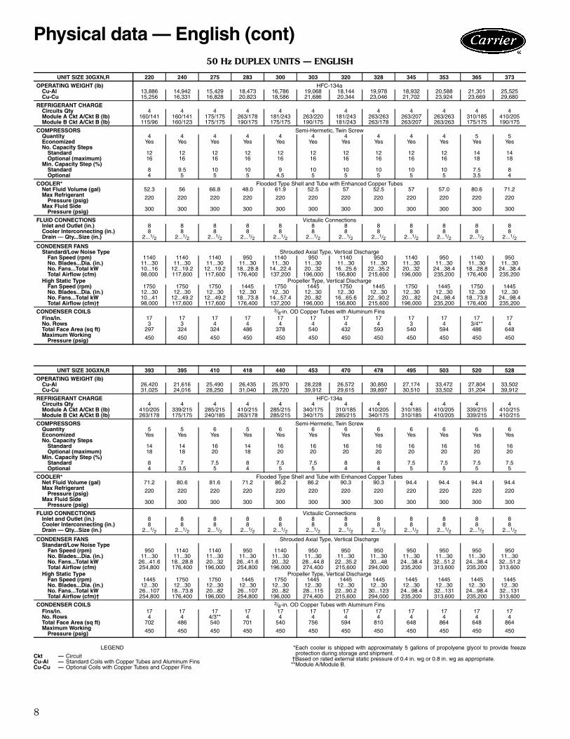
UNIT SIZE 30GXN,R 220 240 275 283 300 303 320 328 345 353 365 373OPERATING WEIGHT (kg)
Cu-Al 6299 6777 6998 8379 7614 8649 8230 9 062 8588 9 339 9 662 11 578Cu-Cu 6920 7408 7633 9445 8431 9837 9228 10 454 9844 10 852 10 736 13 463
REFRIGERANT CHARGE HFC-134aCircuits Qty 4 4 4 4 4 4 4 4 4 4 4 4Module A Ckt A/Ckt B (kg) 73/64 73/64 79/79 119/81 82/110 119/100 82/110 119/119 119/94 119/119 141/84 186/93Module B Ckt A/Ckt B (kg) 52/44 73/56 79/79 86/79 79/79 86/79 82/110 119/81 119/94 119/119 79/79 86/79
COMPRESSORS Semi-Hermetic, Twin ScrewQuantity 4 4 4 4 4 4 4 4 4 4 5 5Economized Yes Yes Yes Yes Yes Yes Yes Yes Yes Yes Yes YesNo. Capacity Steps
Standard 12 12 12 12 12 12 12 12 12 12 14 14Optional (maximum) 16 16 16 16 16 16 16 16 16 16 18 18
Min. Capacity Step (%)Standard 8 9.5 10 10 9 10 10 10 10 10 7.5 8Optional 4 5 5 5 4.5 5 5 5 5 5 3.5 4
COOLER* Flooded Type Shell and Tube with Enhanced Copper TubesNet Fluid Volume (L) 198.0 212.0 252.9 182 234.3 199 215.8 199 215.8 216 305.1 270Max Refrigerant Pressure (kPa) 1517 1517 1517 1517 1517 1517 1517 1517 1517 1517 1517 1517Max Fluid Side Pressure (kPa) 2069 2069 2069 2069 2069 2069 2069 2069 2069 2069 2069 2069
FLUID CONNECTIONS Victaulic ConnectionsInlet and Outlet (in.) 8 8 8 8 8 8 8 8 8 8 8 8Cooler Interconnecting (in.) 8 8 8 8 8 8 8 8 8 8 8 8Drain — Qty...Size (in.) 2...1/2 2...1/2 2...1/2 2...1/2 2...1/2 2...1/2 2...1/2 2...1/2 2...1/2 2...1/2 2...1/2 2...1/2
CONDENSER FANSStandard/Low Noise Type Shrouded Axial Type, Vertical Discharge
Fan Speed (r/s) 24.1 24.1 24.1 24.1 24.1 24.1 24.1 24.1 24.1 24.1 24.1 24.1No. Blades...Dia (mm) 11...762 11...762 11...762 11...762 11...762 11...762 11...762 11...762 11...762 11...762 11...762 11...762No. Fans...Total kW 10...16 12...19.2 12...19.2 18...28.8 14...22.4 20...32 16...25.6 22...35.2 20...32 24...38.4 18...28.8 24...38.4Total Airflow (L/s) 46 251 55 502 55 502 83 252 64 752 92 502 74 002 101 752 92 503 111 003 83 252 111 003
High Static Type Propeller Type, Vertical DischargeFan Speed (r/s) 24.1 2.41 24.1 24.1 24.1 24.1 24.1 24.1 24.1 24.1 24.1 24.1No. Blades...Dia (mm) 12...762 12...762 12...762 12...762 12...762 12...762 12...762 12...762 12...762 12...762 12...762 12...762No. Fans...Total kW 10...41 12...49.2 12...49.2 18...73.8 14...57.4 20...82 16...65.6 22...90.2 20...82 24...98.4 18...73.8 24...98.4Total Airflow (L/s)† 46 251 55 502 55 502 83 252 64 752 92 502 74 002 101 752 92 503 111 003 83 252 111 003
CONDENSER COILS 3/8-in. OD Copper Tubes with Aluminum FinsFins/m 669 669 669 669 669 669 669 669 669 669 669 669No. Rows 3 3 4 4 4 4 4 4 3 4 3/4** 4Total Face Area (sq m) 27.6 30.1 30.1 45.2 35.1 50.2 40.1 55.2 50.2 60.2 45.2 60.2Maximum Working
Pressure (kPa) 3103 3103 3103 3103 3103 3103 3103 3103 3103 3103 3103 3103
UNIT SIZE 30GXN,R 393 395 410 418 440 453 470 478 495 503 520 528OPERATING WEIGHT (kg) HFC-134a
Cu-Al 11 984 9 805 11 562 11 991 11 780 12 804 12 180 13 994 12 580 15 183 12 612 15 197Cu-Cu 14 073 10 894 12 814 14 080 13 027 18 104 13 575 18 097 14 122 15 197 14 154 18 104
REFRIGERANT CHARGECircuits Qty 4 4 4 4 4 4 4 4 4 4 4 4Module A Ckt A/Ckt B (kg) 186/93 154/98 129/98 186/98 129/98 154/79 141/84 186/93 141/84 186/93 154/98 186/98Module B Ckt A/Ckt B (kg) 119/81 79/79 109/84 119/81 129/98 154/79 129/98 154/79 141/84 186/93 154/98 186/98
COMPRESSORS Semi-Hermetic, Twin ScrewQuantity 5 5 6 5 6 6 6 6 6 6 6 6Economized Yes Yes Yes Yes Yes Yes Yes Yes Yes Yes Yes YesNo. Capacity Steps
Standard 14 14 16 14 16 16 16 16 16 16 16 16Optional (maximum) 18 18 20 18 20 20 20 20 20 20 20 20
Min. Capacity Step (%)Standard 8 7 7.5 8 7.5 7.5 8 8 7.5 7.5 7.5 7.5Optional 4 3.5 5 4 5 5 4 4 5 5 5 5
COOLER* Flooded Type Shell and Tube with Enhanced Copper TubesNet Fluid Volume (L) 270 305.1 308.9 270 326.3 326 342 342 357 357 357 357Max Refrigerant Pressure (kPa) 1517 1517 1517 1517 1517 1517 1517 1517 1517 1517 1517 1517Max Fluid Side Pressure (kPa) 2069 2069 2069 2069 2069 2069 2069 2069 2069 2069 2069 2069
FLUID CONNECTIONS Victaulic ConnectionsInlet and Outlet (in.) 8 8 8 8 8 8 8 8 8 8 8 8Cooler Interconnecting (in.) 8 8 8 8 8 8 8 8 8 8 8 8Drain — Qty...Size (in.) 2...1/2 2...1/2 2...1/2 2...1/2 2...1/2 2...1/2 2...1/2 2...1/2 2...1/2 2...1/2 2...1/2 2...1/2
CONDENSER FANSStandard/Low Noise Type Shrouded Axial Type, Vertical Discharge
Fan speed (r/s) 24.1 24.1 24.1 24.1 24.1 24.1 24.1 24.1 24.1 24.1 24.1 24.1No. Blades...Dia (mm) 11...762 11...762 11...762 11...762 11...762 11...762 11...762 11...762 11...762 11...762 11...762 11...762No. Fans...Total kW 26...41.6 18...28.8 20 26...41.6 20 28...44.8 22...35.2 30...48 24...38.4 32...51.2 24...38.4 32...51.2Total Airflow (L/s) 120 253 83 252 92 503 120 253 92 503 129 503 101 752 138 753 111 003 148 004 111 003 148 004
High Static Type Propeller Type, Vertical DischargeFan Speed (r/s) 24.1 24.1 24.1 24.1 24.1 24.1 24.1 24.1 24.1 24.1 24.1 24.1No. Blades...Dia (mm) 12...762 12...762 12...762 12...762 12...762 12...762 12...762 12...762 12...762 12...762 12...762 12...762No. Fans...Total kW 26...107 18...73.8 20...82 26...107 20...32 28...115 22...90.2 30...123 24...98.4 32...131 24...98.4 32...131Total Airflow (L/s)† 120 253 83 252 92 503 120 253 92 503 129 503 101 752 138 753 111 003 148 004 111 003 148 004
CONDENSER COILS 3/8-in. OD Copper Tubes with Aluminum FinsFins/m 669 669 669 669 669 669 669 669 669 669 669 669No. Rows 4 4 4/3** 4 4 4 4 4 5 4 4 4Total Face Area (sq m) 65.2 45.2 50.2 65.2 50.2 70.2 55.2 75.3 60.2 80.3 60.2 80.3Maximum Working
Pressure (kPa) 3103 3103 3103 3103 3103 3103 3103 3103 3103 3103 3103 3103
Ckt — CircuitCu-Al — Standard Coils with Copper Tubes and Aluminum FinsCu-Cu — Optional Coils with Copper Tubes and Copper Fins
Physical data (cont)

7
50 Hz UNITS — ENGLISH
LEGEND *Each cooler is shipped with approximately 5 gallons of propolyene glycol to provide freeze pro-tection during storage and shipment.
†Based on rated external static pressure of 0.4 in. wg or 0.8 in. wg as appropriate.
UNIT SIZE 30GXN,R 080 083 090 093 106 108 115 118 125 128 135 138 150 153 160
OPERATING WEIGHT (lb)Cu-Al 6313 6907 6333 7201 7514 7662 7388 8649 7553 8664 7714 8789 8784 9,684 9,072Cu-Cu 6988 7602 7008 7896 8209 8357 8083 9699 8248 9714 8414 9739 9834 11,084 10,172
REFRIGERANT TYPE HFC-134aRefrigerant Charge (lb)
Ckt-A/Ckt-B 106/96 128/123 115/96 135/123 150/123 135/123 160/123 170/151 160/141 190/151 175/175 190/175 156/228 263/178 181/243
COMPRESSORS Semi-Hermetic, Twin ScrewQuantity 2 2 2 2 2 2 2 2 2 2 2 2 2 2 2Economized No No No No No Yes Yes Yes Yes Yes Yes Yes Yes Yes YesNo. Capacity Steps
Standard 6 6 6 6 6 6 6 6 6 6 6 6 6 6 6Optional (maximum) 8 8 8 8 8 8 8 8 8 8 8 8 8 8 8
Min. Capacity Step (%)Standard 20 20 20 20 20 20 20 20 20 20 20 20 20 20 20Optional 10 10 10 10 10 10 10 10 10 10 10 10 10 10 10
COOLER* Flooded Type Shell and Tube with Enhanced Copper TubesNet Fluid Volume (gal) 18.9 18.9 18.9 18.9 22.6 22.6 22.6 20.9 33.4 24 33.4 24 24 24 28.5Maximum Refrigerant
Pressure (psig) 220 220 220 220 220 220 220 220 220 220 220 220 220 220 220
Maximum Fluid SidePressure (psig) 300 300 300 300 300 300 300 300 300 300 300 300 300 300 300
FLUID CONNECTIONS (in.) Victaulic ConnectionsInlet and Outlet 4 4 4 4 5 5 5 4 5 4 5 4 4 4 5Drain (NPT) 1/2 1/2 1/2 1/2 1/2 1/2 1/2 1/2 1/2 1/2 1/2 1/2 1/2 1/2 1/2
CONDENSER FANSStandard/Low Noise Type Shrouded Axial Type, Vertical Discharge
Fan Speed (rpm) 950 950 950 950 950 950 950 950 950 950 950 950 950 950 950No. Blades...Dia. (in.) 11...30 11...30 11...30 11...30 11...30 11...30 11...30 11...30 11...30 11...30 11...30 11...30 11...30 11...30 11...30No. Fans...Total kW 4...6.4 6...9.6 4...6.4 6...9.6 6...9.6 6...9.6 6...9.6 8...12.8 6...9.6 8...12.8 6...9.6 8...12.8 8...12.8 10...16 8...12.8Total Airflow (cfm) 39,200 58,800 39,200 58,800 58,800 58,800 58,800 78,400 58,800 78,400 58,800 78,400 78,400 98,000 78,400
High Static Type Propeller Type, Vertical DischargeFan Speed (rpm) 1445 1445 1445 1445 1445 1445 1445 1445 1445 1445 1445 1445 1445 1445 1445No. Blades...Dia. (in.) 12...30 12...30 12...30 12...30 12...30 12...30 12...30 12...30 12...30 12...30 12...30 12...30 12...30 12...30 12...30No. Fans...Total kW 4...16.4 6...24.6 4...16.4 6...24.6 6...24.6 6...24 6...24.6 8...32.8 6...24.6 8...32.8 6...24.6 8...32.8 8...32.8 10...41 8...32.8Total Airflow (cfm)† 39,200 58,800 39,200 58,800 58,800 58,800 58,800 78,400 58,800 78,400 78,400 78,400 78,400 98,000 78,400
CONDENSER COILS 3/8-in. OD Copper Tubes with Aluminum FinsFins/in. 17 17 17 17 17 17 17 17 17 17 17 17 17 17 17No. Rows 3 3 3 4 4 4 3 4 3 4 4 4 4 4 4Total Face Area (sq ft) 135 162 135 162 162 162 162 216 162 216 162 216 216 270 216Maximum Working
Pressure (psig) 450 450 450 450 450 450 450 450 450 450 450 450 450 450 450
UNIT SIZE 30GXN,R 163 175 178 205 208 225 228 250 253 264 268 281 301 325 350
OPERATING WEIGHT (lb)Cu-Al 10,279 9,466 10,294 12,505 14,099 12,985 14,114 13,587 16,736 13,902 16,751 18,718 18,738 18,778 18,828Cu-Cu 11,947 10,851 11,962 13,890 19,941 14,360 19,956 15,255 19,941 15,602 19,956 21,923 21,943 21,983 22,033
REFRIGERANT TYPE HFC-134aRefrigerant Charge (lb)
Ckt-A/Ckt-B 263/220 263/207 263/263 240/185 330/175 285/215 340/175 310/185 410/205 339/215 410/215 385/385 400/400 415/415 430/430
COMPRESSORS Semi-Hermetic, Twin ScrewQuantity 2 2 2 3 3 3 3 3 3 3 3 4 4 4 4Economized Yes Yes Yes Yes Yes Yes Yes Yes Yes Yes Yes Yes Yes Yes YesNo. Capacity Steps
Standard 6 6 6 8 8 8 8 8 8 8 8 10 10 10 10Optional (maximum) 8 8 8 10 10 10 10 10 10 10 10 12 12 12 12
Min. Capacity Step (%)Standard 20 20 20 15 15 15 15 15 15 15 15 10 10 10 10Optional 10 10 10 10 10 10 10 10 10 10 10 5 5 5 5
COOLER* Flooded Type Shell and Tube with Enhanced Copper TubesNet Fluid Volume (gal) 28.5 28.5 28.5 38.5 38.5 43.1 43.1 47.2 47.2 47.2 47.2 56.1 56.1 56.1 56.1Maximum Refrigerant
Pressure (psig) 220 220 220 220 220 220 220 220 220 220 220 220 220 220 220
Maximum Fluid SidePressure (psig) 300 300 300 300 300 300 300 300 300 300 300 300 300 300 300
FLUID CONNECTIONS (in.) Victaulic ConnectionsInlet and Outlet 5 5 5 6 6 6 6 6 6 6 6 8 8 8 8Drain (NPT) 1/2 1/2 1/2 1/2 1/2 1/2 1/2 1/2 1/2 1/2 1/2 1/2 1/2 1/2 1/2
CONDENSER FANSStandard/Low Noise Type Shrouded Axial Type, Vertical Discharge
Fan Speed (rpm) 950 950 950 950 950 950 950 950 950 950 960 950 950 950 950No. Blades...Dia. (in.) 11...30 11...30 11...30 11...30 11...30 11...30 11...30 11...30 11...30 11...30 11...30 11...30 11...30 11...30 11...30No. Fans...Total kW 12...19.2 10...16 12...19.2 10...16 14...22.4 10...16 14...22.4 12...19.2 16...25.6 12...19.2 16...25.6 16...25.6 16...25.6 16...25.6 16...25.6Total Airflow (cfm) 117,600 98,000 117,600 98,000 137,200 98,000 137,200 117,600 158,600 117,600 158,600 156,800 156,800 156,800 156,800
High Static Type Propeller Type, Vertical DischargeFan Speed (rpm) 1445 1445 1445 1445 1445 1445 1445 1445 1445 1445 1445 1445 1445 1445 1445No. Blades...Dia. (in.) 12...30 12...30 12...30 12...30 12...30 12...30 12...30 12...30 12...30 12...30 12...30 12...30 12...30 12...30 12...30No. Fans...Total kW 12...49.2 10...41 12...49.2 10...41 14...57.4 10...41 14...57.4 12...49.2 16...65.6 12...49.2 16...65.6 16...65.6 16...65.6 16...65.6 16...65.6Total Airflow (cfm)† 117,600 98,000 117,600 98,000 137,200 98,000 137,200 117,600 158,600 117,600 158,600 158,600 158,600 158,600 158,600
CONDENSER COILS 3/8-in. OD Copper Tubes with Aluminum FinsFins/in. 17 17 17 17 17 17 17 17 17 17 17 17 17 17 17No. Rows 4 3 4 3 4 4 4 3 4 4 4 4 4 4 4Total Face Area (sq ft) 324 270 324 270 378 270 378 324 432 324 432 432 432 432 432Maximum Working
Pressure (psig) 450 450 450 450 450 450 450 450 450 450 450 450 450 450 450
Ckt — CircuitCu-Al — Standard Coils with Copper Tubes and Aluminum FinsCu-Cu — Optional Coils with Copper Tubes and Copper Fins
Physical data — English
8
50 Hz DUPLEX UNITS — ENGLISH
LEGEND *Each cooler is shipped with approximately 5 gallons of propolyene glycol to provide freezeprotection during storage and shipment.
†Based on rated external static pressure of 0.4 in. wg or 0.8 in. wg as appropriate.**Module A/Module B.
UNIT SIZE 30GXN,R 220 240 275 283 300 303 320 328 345 353 365 373
OPERATING WEIGHT (lb) HFC-134aCu-Al 13,886 14,942 15,429 18,473 16,786 19,068 18,144 19,978 18,932 20,588 21,301 25,525Cu-Cu 15,256 16,331 16,828 20,823 18,586 21,686 20,344 23,046 21,702 23,924 23,669 29,680
REFRIGERANT CHARGECircuits Qty 4 4 4 4 4 4 4 4 4 4 4 4Module A Ckt A/Ckt B (lb) 160/141 160/141 175/175 263/178 181/243 263/220 181/243 263/263 263/207 263/263 310/185 410/205Module B Ckt A/Ckt B (lb) 115/96 160/123 175/175 190/175 175/175 190/175 181/243 263/178 263/207 263/263 175/175 190/175
COMPRESSORS Semi-Hermetic, Twin ScrewQuantity 4 4 4 4 4 4 4 4 4 4 5 5Economized Yes Yes Yes Yes Yes Yes Yes Yes Yes Yes Yes YesNo. Capacity Steps
Standard 12 12 12 12 12 12 12 12 12 12 14 14Optional (maximum) 16 16 16 16 16 16 16 16 16 16 18 18
Min. Capacity Step (%)Standard 8 9.5 10 10 9 10 10 10 10 10 7.5 8Optional 4 5 5 5 4.5 5 5 5 5 5 3.5 4
COOLER* Flooded Type Shell and Tube with Enhanced Copper TubesNet Fluid Volume (gal) 52.3 56 66.8 48.0 61.9 52.5 57 52.5 57 57.0 80.6 71.2Max Refrigerant
Pressure (psig) 220 220 220 220 220 220 220 220 220 220 220 220
Max Fluid SidePressure (psig) 300 300 300 300 300 300 300 300 300 300 300 300
FLUID CONNECTIONS Victaulic ConnectionsInlet and Outlet (in.) 8 8 8 8 8 8 8 8 8 8 8 8Cooler Interconnecting (in.) 8 8 8 8 8 8 8 8 8 8 8 8Drain — Qty...Size (in.) 2...1/2 2...1/2 2...1/2 2...1/2 2...1/2 2...1/2 2...1/2 2...1/2 2...1/2 2...1/2 2...1/2 2...1/2
CONDENSER FANSStandard/Low Noise Type Shrouded Axial Type, Vertical Discharge
Fan Speed (rpm) 1140 1140 1140 950 1140 950 1140 950 1140 950 1140 950No. Blades...Dia. (in.) 11...30 11...30 11...30 11...30 11...30 11...30 11...30 11...30 11...30 11...30 11...30 11...30No. Fans...Total kW 10...16 12...19.2 12...19.2 18...28.8 14...22.4 20...32 16...25.6 22...35.2 20...32 24...38.4 18...28.8 24...38.4Total Airflow (cfm) 98,000 117,600 117,600 176,400 137,200 196,000 156,800 215,600 196,000 235,200 176,400 235,200
High Static Type Propeller Type, Vertical DischargeFan Speed (rpm) 1750 1750 1750 1445 1750 1445 1750 1445 1750 1445 1750 1445No. Blades...Dia. (in.) 12...30 12...30 12...30 12...30 12...30 12...30 12...30 12...30 12...30 12...30 12...30 12...30No. Fans...Total kW 10...41 12...49.2 12...49.2 18...73.8 14...57.4 20...82 16...65.6 22...90.2 20....82 24...98.4 18...73.8 24...98.4Total Airflow (cfm)† 98,000 117,600 117,600 176,400 137,200 196,000 156,800 215,600 196,000 235,200 176,400 235,200
CONDENSER COILS 3/8-in. OD Copper Tubes with Aluminum FinsFins/in. 17 17 17 17 17 17 17 17 17 17 17 17No. Rows 3 3 4 4 4 4 4 4 3 4 3/4** 4Total Face Area (sq ft) 297 324 324 486 378 540 432 593 540 594 486 648Maximum Working
Pressure (psig) 450 450 450 450 450 450 450 450 450 450 450 450
UNIT SIZE 30GXN,R 393 395 410 418 440 453 470 478 495 503 520 528
OPERATING WEIGHT (lb)Cu-Al 26,420 21,616 25,490 26,435 25,970 28,228 26,572 30,850 27,174 33,472 27,804 33,502Cu-Cu 31,025 24,016 28,250 31,040 28,720 39,912 29,615 39,897 30,510 33,502 31,204 39,912
REFRIGERANT CHARGE HFC-134aCircuits Qty 4 4 4 4 4 4 4 4 4 4 4 4Module A Ckt A/Ckt B (lb) 410/205 339/215 285/215 410/215 285/215 340/175 310/185 410/205 310/185 410/205 339/215 410/215Module B Ckt A/Ckt B (lb) 263/178 175/175 240/185 263/178 285/215 340/175 285/215 340/175 310/185 410/205 339/215 410/215
COMPRESSORS Semi-Hermetic, Twin ScrewQuantity 5 5 6 5 6 6 6 6 6 6 6 6Economized Yes Yes Yes Yes Yes Yes Yes Yes Yes Yes Yes YesNo. Capacity Steps
Standard 14 14 16 14 16 16 16 16 16 16 16 16Optional (maximum) 18 18 20 18 20 20 20 20 20 20 20 20
Min. Capacity Step (%)Standard 8 7 7.5 8 7.5 7.5 8 8 7.5 7.5 7.5 7.5Optional 4 3.5 5 4 5 5 4 4 5 5 5 5
COOLER* Flooded Type Shell and Tube with Enhanced Copper TubesNet Fluid Volume (gal) 71.2 80.6 81.6 71.2 86.2 86.2 90.3 90.3 94.4 94.4 94.4 94.4Max Refrigerant
Pressure (psig) 220 220 220 220 220 220 220 220 220 220 220 220
Max Fluid SidePressure (psig) 300 300 300 300 300 300 300 300 300 300 300 300
FLUID CONNECTIONS Victaulic ConnectionsInlet and Outlet (in.) 8 8 8 8 8 8 8 8 8 8 8 8Cooler Interconnecting (in.) 8 8 8 8 8 8 8 8 8 8 8 8Drain — Qty...Size (in.) 2...1/2 2...1/2 2...1/2 2...1/2 2...1/2 2...1/2 2...1/2 2...1/2 2...1/2 2...1/2 2...1/2 2...1/2
CONDENSER FANS Shrouded Axial Type, Vertical DischargeStandard/Low Noise Type
Fan Speed (rpm) 950 1140 1140 950 1140 950 950 950 950 950 950 950No. Blades...Dia. (in.) 11...30 11...30 11...30 11...30 11...30 11...30 11...30 11...30 11...30 11...30 11...30 11...30No. Fans...Total kW 26...41.6 18...28.8 20...32 26...41.6 20...32 28...44.8 22...35.2 30...48 24...38.4 32...51.2 24...38.4 32...51.2Total Airflow (cfm) 254,800 176,400 196,000 254,800 196,000 274,400 215,600 294,000 235,200 313,600 235,200 313,600
High Static Type Propeller Type, Vertical DischargeFan Speed (rpm) 1445 1750 1750 1445 1750 1445 1445 1445 1445 1445 1445 1445No. Blades...Dia. (in.) 12...30 12...30 12...30 12...30 12...30 12...30 12...30 12...30 12...30 12...30 12...30 12...30No. Fans...Total kW 26...107 18...73.8 20...82 26...107 20...82 28...115 22...90.2 30...123 24...98.4 32...131 24...98.4 32...131Total Airflow (cfm)† 254,800 176,400 196,000 254,800 196,000 274,400 215,600 294,000 235,200 313,600 235,200 313,600
CONDENSER COILS 3/8-in. OD Copper Tubes with Aluminum FinsFins/in. 17 17 17 17 17 17 17 17 17 17 17 17No. Rows 4 4 4/3** 4 4 4 4 4 4 4 4 4Total Face Area (sq ft) 702 486 540 701 540 756 594 810 648 864 648 864Maximum Working
Pressure (psig) 450 450 450 450 450 450 450 450 450 450 450 450
Ckt — CircuitCu-Al — Standard Coils with Copper Tubes and Aluminum FinsCu-Cu — Optional Coils with Copper Tubes and Copper Fins
Physical data — English (cont)

9
Factory-installed options115 F (46.1 C) electric service rating — Lower elec-tric service temperature ratings reduce the units rated Mini-mum Current Amps (MCA) and Maximum OvercurrentProtection (MOCP) for moderate ambient temperatureapplications (sizes 080 to 125, 220, 240 and all high effi-ciency models).125 F (51.7 C) electric service rating — Higher elec-tric service temperature ratings allows maximum ambienttemperature operation.Remote service port — Provides secondary connectionport for Navigator display. Port is conveniently locatedoutside of the control box for easy access to informationduring operation and maintenance routines.Low ambient protection to 0° F (–17.7 C) — Factory-installed cooler head heaters and liquid line solenoid valvescombined with a pump down cycle provide cooler ambientprotection to 0° F (–17.7 C). Cooler head insulation isrequired with this option.
Energy Management Module — This module providesenergy management capabilities to minimize chiller energyconsumption. Several features are provided with this mod-ule including leaving fluid temperature reset, cooling setpoint selection or demand limit control from a 4 to 20 mAsignal, 2-step demand limit control (from 0 to 100%) acti-vated by a remote contact closure, and discrete input for“Ice Done” indication for ice storage system interface.Wye-delta start — Reduced inrush current start is avail-able as a factory-installed option.Condenser coil options (Enviro-Shield™) — Severaloptions are available to match coil construction to the siteconditions for the best durability. Consult your Carrier rep-resentative for further information.
Alternate cooler heads (plus one pass, minus onepass) — This option changes the standard cooler head toa Plus-One-Pass (for use with low temperature brines), or aMinus-One-Pass (reduced pressure drop for series flowapplications). Consult the Carrier 30GXN,R electronic cat-alog for performance data.Suction isolation valves — Standard refrigerant dis-charge isolation and liquid valves enable service personnelto store the refrigerant charge in the cooler or condenserduring servicing. This factory-installed option allows forfurther isolation of the compressor from the cooler vessel.Medium temperature brine — This option permits sup-ply liquid temperatures to be set below 40 F (4.4 C).Refrigeration circuit components, such as the expansiondevice, are modified at the factory to adjust for lower refrig-erant flow rates.Low-ambient operation Motormaster® control —This factory-installed option permits operation of the30GXN,R units down to –20 F (–29 C) outdoor ambienttemperature. The control is also available as a field-installedaccessory. Also requires field-installed wind baffles. (Motor-master control cannot be used with high-static fan option.)Non-fused disconnect — This option provides non-fuseddisconnect capability for main unit power located at the unit.High-static condenser fans — The high-static fansallow the 30GXN,R unit to be used in applications with anexternal static pressure of up to 0.8 in. wg (200 Pa) atnominal condenser airflow. Two options are available: 0.4in. wg (100 Pa) or 0.8 in. wg (200 Pa). (Not for use withMotormaster control.)Minimum load control — This option allows additionalcapacity reduction for unit operation below the minimumstep of unloading (down to 10% of the unit capacity).Minimum load control is also available as a field-installedaccessory.High ambient fans — This option increases condenserairflow through the use of a variation of the Flying Bird fanand higher capacity motors and provides better perfor-mance at extreme ambient temperature. (Not for use withMotormaster control.)
ITEM FACTORY-INSTALLED OPTION FIELD-INSTALLED ACCESSORYRemote Service Port X XWye-Delta Start XCopper-Fin Condenser Coil XEnviro-Shield™ System Condenser Coil Coatings XAlternate Cooler Heads (plus 1 pass, minus 1 pass) XSuction Isolation Valves XMedium Temperature Brine XNon-Fused Disconnect XHigh-Static/High Ambient Condenser Fans XLow-Ambient Control X XLow-Ambient Protection XMinimum Load Control X XSecurity Guards XControl Display Access Door XCooler Head Insulation XRemote Enhanced Display XChillervisor System Manager III Multi-Unit Control X125 F (51.7 C) Electric Service Relay X115 F (46.1 C) Electric Service Relay XSound Reduction Enclosure/Hail Guards/Wind Baffles XVibration Isolation XTrim Kit XEnergy Management Module X XHigh Ambient Fans XDuplex Flex Pipe X
IMPORTANT: Adding antifreeze solution is the onlycertain means of protecting the unit from freeze-up ifheater fails or electrical service is interrupted during lowtemperatures.
Options and accessories

10
CONDENSER COIL CORROSION PROTECTION OPTIONS
LEGEND
*See page 74 for further description, also see “Environmental Corrosion Protection” for more information (Publications 810-217 and 811-019).
Packaging options — Several packaging options areavailable to provide unit protection during transit to the jobsite.
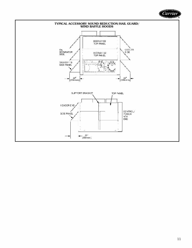
Field-installed accessoriesSecurity guards — This accessory covers the condensercoils, cooler, and compressor areas to protect the unit fromintrusion.Minimum load control — This option allows additionalcapacity reduction for unit operation below the minimumstep of unloading (down to 10% of the minimum unitcapacity). Minimum load control is also available as afactory-installed option.Control display access door — This option provideseasy access to the unit control module through asee-through door without having to open or remove thecontrol box panels.Remote enhanced display — This accessory kit con-tains a remotely mounted 40-character per line, 16-linedisplay panel for unit diagnostics. (for indoor use only)Chillervisor System Manager III multi-unit control— This accessory allows sequencing of between 3 and 8chillers in parallel. Pump control is also provided.Sound reduction enclosures/hail guards/wind baffles— This kit contains a sound enclosure that covers the entireunit to reduce sound levels. Coil protection and wind bafflesare also provided. See Carrier electronic catalog 30GXN,Rchiller program for sound power data and dBA reduction.Low ambient Motormaster head pressure control— Permits starting and operating down to –20 F (–29 C)outside ambient temperature. Requires field-installed windbaffles. (Motormaster control cannot be used with high-static fan option.)
Energy Management Module — This module providesenergy management capabilities to minimize chiller energyconsumption. Several features are provided with this mod-ule including leaving fluid temperature reset, cooling setpoint selection or demand limit control from a 4 to 20 mAsignal; 2-step demand limit control (from 0 to 100%) acti-vated by a remote contact closure; and discrete input for“Ice Done” indication for ice storage system interface.Vibration isolation — The field-installed 1/4-in. neo-prene isolator pads (24-in. x 3-in.) reduce vibration trans-mission from the compressor through the floor and intothe conditioned space.Cooler head insulation — This accessory is designedwith flexible, 3/4-in. (19 mm) PVC foam (closed-cell) toinsulate the cooler heads and economizer vessel to mini-mize heat loss and head sweating.Remote service port — Provides secondary connectionport for Navigator display. Port is conveniently located out-side of the control box for easy access to information dur-ing operation and maintenance routines.Duplex trim kit accessory — The duplex trim kit acces-sory is available for field installation between unit modules.The kit contains sheet metal base rail pieces and allrequired mounting hardware. The kit also allows for inter-connecting piping support.Duplex flex pipe — An 8 in. x 16 in. flexible pipe isavailable for duplex piping to provide chilled water vibra-tion isolation and to complete piping between modules.
ENVIRO-SHIELD™OPTION*
ENVIRONMENT
Standard MildCoastal
ModerateCoastal
SevereCoastal Industrial Combined
Industrial/CoastalAL Fins (Standard Coils) XCU Fins XAL Fins, E-coat X XCU Fins, E-coat XAL Fins, Precoated X
AL — AluminumCU — Copper
OPTION 1 Standard domestic packaging includes a rigid board to protect the condenser coils from physical abrasion.OPTION 2 Includes Option 1 plus a bottom wooden skid.
OPTION 3 Standard export packaging with rigid board coil cover, top and bottom wooden skid & reinforced polymer bag to protect entire unit from splashing waterand debris.
OPTION 4 Full wooden crate surrounding entire unit.
OPTION 5 Option #1 above with factory-installed security grilles.OPTION 6 Option #2 above with factory-installed security grilles.OPTION 7 Option #3 above with factory-installed security grilles.
OPTION 8 Option #4 above with factory-installed security grilles.
Options and accessories (cont)
11
TYPICAL ACCESSORY SOUND REDUCTION/HAIL GUARD/WIND BAFFLE HOODS

12
Dimensions
30G
XN
,R080, 090

13
30G
XN
,R083, 093, 106, 108, 115, 125, 135
14
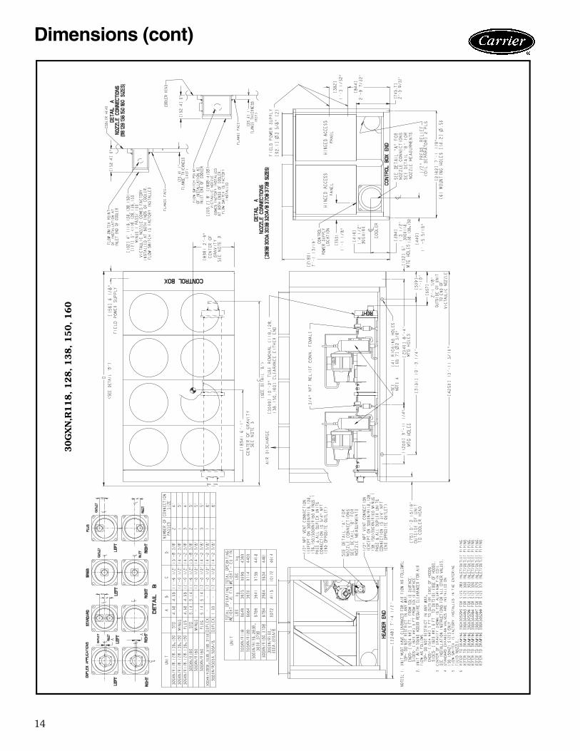
Dimensions (cont)
30G
XN
,R118, 128, 138, 150, 160

15
30G
XN
,R153, 175

16
Dimensions (cont)
30G
XN
,R163, 178

17
30G
XN
,R205, 225

18
Dimensions (cont)
30G
XN
,R208, 228

19
30G
XN
,R250, 264

20
Dimensions (cont)
30G
XN
,R253, 268

21
30G
XN
,R281-3
50
22
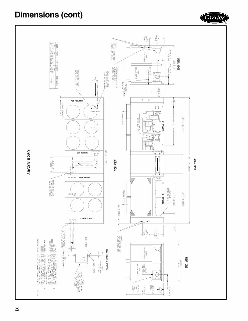
Dimensions (cont)
30G
XN
,R220
23
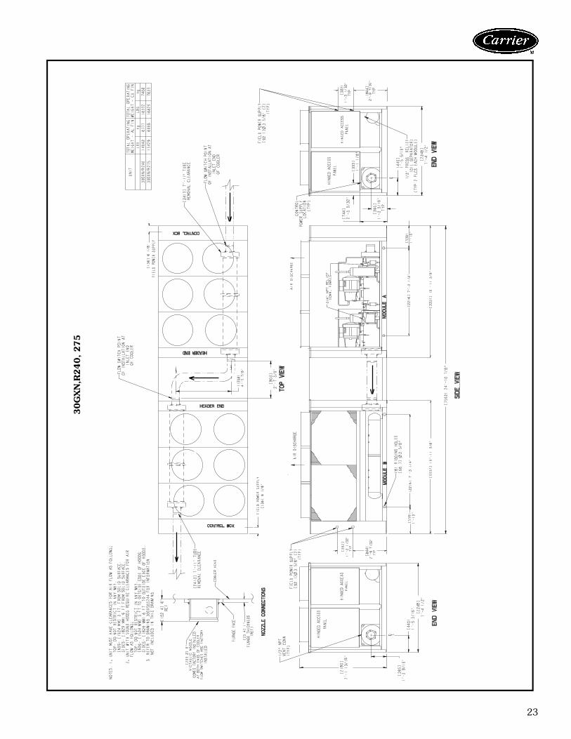
30G
XN
,R240, 275

24
Dimensions (cont)
30G
XN
,R283

25
30G
XN
,R300

26
Dimensions (cont)
30G
XN
,R303
27
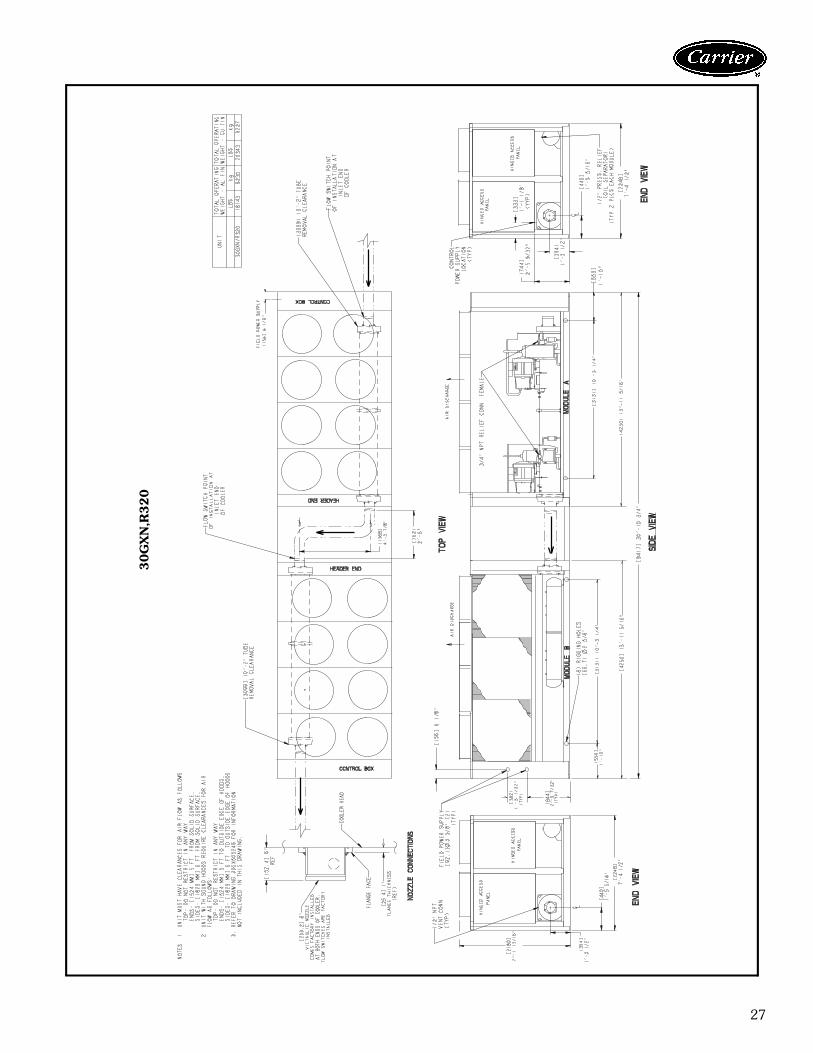
30G
XN
,R320

28
Dimensions (cont)
30G
XN
,R328
29
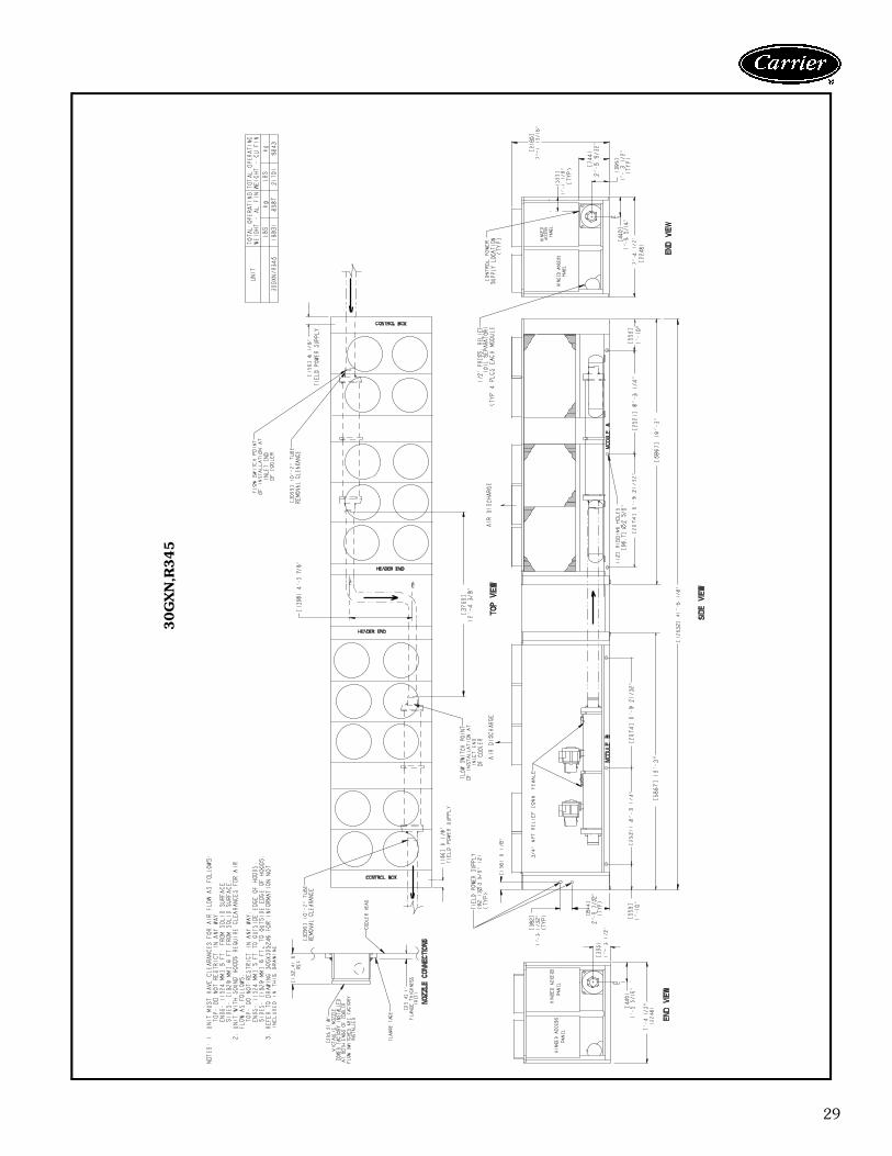
30G
XN
,R345

30
Dimensions (cont)
30G
XN
,R353
31
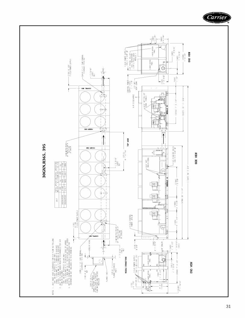
30G
XN
,R365, 395

32
Dimensions (cont)
30G
XN
,R373

33
30G
XN
,R393, 418

34
Dimensions (cont)
30G
XN
,R410, 440

35
30G
XN
,R453

36
Dimensions (cont)
30G
XN
,R470

37
30G
XN
,R478
38
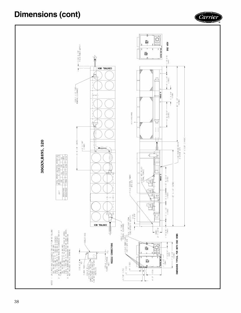
Dimensions (cont)
30G
XN
,R495, 520
39
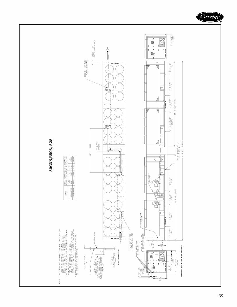
30G
XN
,R503, 528
40
Dimensions (cont)
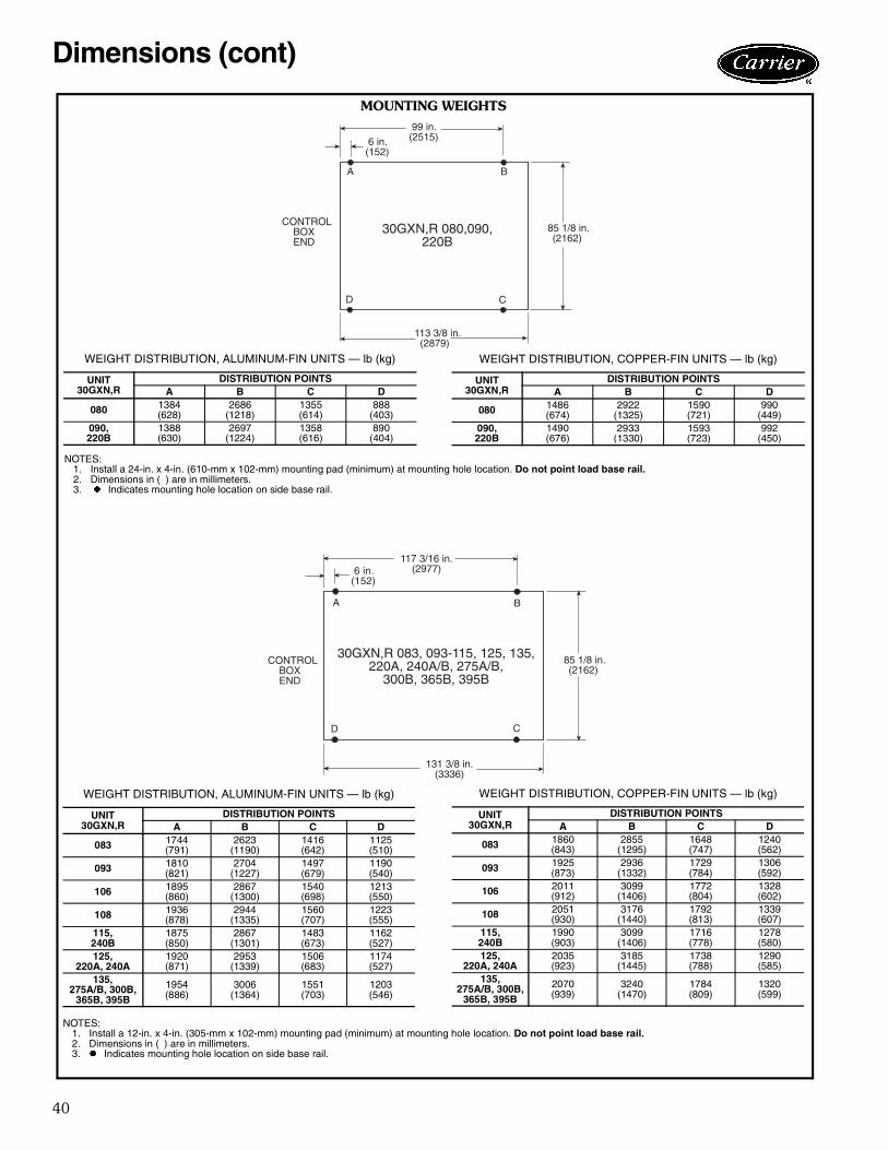
99 in.(2515)6 in.
(152)
D C
113 3/8 in.(2879)
A B
CONTROLBOXEND
85 1/8 in.(2162)
30GXN,R 080,090,220B
6 in.(152)
D C
A B
CONTROLBOXEND
85 1/8 in.(2162)
131 3/8 in.(3336)
117 3/16 in.(2977)
30GXN,R 083, 093-115, 125, 135,220A, 240A/B, 275A/B,
300B, 365B, 395B
WEIGHT DISTRIBUTION, ALUMINUM-FIN UNITS — lb (kg)
UNIT30GXN,R
DISTRIBUTION POINTSA B C D
080 1384(628)
2686(1218)
1355(614)
888(403)
090,220B
1388(630)
2697(1224)
1358(616)
890(404)
NOTES:1. Install a 24-in. x 4-in. (610-mm x 102-mm) mounting pad (minimum) at mounting hole location. Do not point load base rail.2. Dimensions in ( ) are in millimeters.3. � Indicates mounting hole location on side base rail.
WEIGHT DISTRIBUTION, COPPER-FIN UNITS — lb (kg)
UNIT30GXN,R
DISTRIBUTION POINTSA B C D
080 1486(674)
2922(1325)
1590(721)
990(449)
090,220B
1490(676)
2933(1330)
1593(723)
992(450)
WEIGHT DISTRIBUTION, ALUMINUM-FIN UNITS — lb (kg)
UNIT30GXN,R
DISTRIBUTION POINTSA B C D
083 1744(791)
2623(1190)
1416(642)
1125(510)
093 1810(821)
2704(1227)
1497(679)
1190(540)
106 1895(860)
2867(1300)
1540(698)
1213(550)
108 1936(878)
2944(1335)
1560(707)
1223(555)
115,240B
1875(850)
2867(1301)
1483(673)
1162(527)
125,220A, 240A
1920(871)
2953(1339)
1506(683)
1174(527)
135,275A/B, 300B,
365B, 395B
1954(886)
3006(1364)
1551(703)
1203(546)
NOTES:1. Install a 12-in. x 4-in. (305-mm x 102-mm) mounting pad (minimum) at mounting hole location. Do not point load base rail.2. Dimensions in ( ) are in millimeters.3. � Indicates mounting hole location on side base rail.
WEIGHT DISTRIBUTION, COPPER-FIN UNITS — lb (kg)
UNIT30GXN,R
DISTRIBUTION POINTSA B C D
083 1860(843)
2855(1295)
1648(747)
1240(562)
093 1925(873)
2936(1332)
1729(784)
1306(592)
106 2011(912)
3099(1406)
1772(804)
1328(602)
108 2051(930)
3176(1440)
1792(813)
1339(607)
115,240B
1990(903)
3099(1406)
1716(778)
1278(580)
125,220A, 240A
2035(923)
3185(1445)
1738(788)
1290(585)
135,275A/B, 300B,
365B, 395B
2070(939)
3240(1470)
1784(809)
1320(599)
MOUNTING WEIGHTS

41
WEIGHT DISTRIBUTION, ALUMINUM-FIN UNITS — lb (kg)
UNIT30GXN,R
DISTRIBUTION POINTSA B C D E F
118 1757(797)
2001(907)
1524(691)
809(367)
1261(572)
1298(589)
128 1760(798)
2005(910)
1528(693)
810(367)
1262(573)
1299(589)
138, 283B,303B, 373B
1765(801)
2014(913)
1534(696)
811(368)
1265(574)
1300(590)
150 1770(803)
1982(899)
1666(756)
928(421)
1180(535)
1258(570)
160, 300A,320A/B
1830(830)
2075(941)
1743(790)
948(430)
1204(546)
1273(577)
NOTES:1. Install a 24-in. x 4-in. (610-mm x 102-mm) mounting pad (minimum) at mounting hole location. Do not point load base rail.2. Dimensions in ( ) are in millimeters.3. � Indicates mounting hole location on side base rail.
WEIGHT DISTRIBUTION, COPPER-FIN UNITS — lb (kg)
UNIT30GXN,R
DISTRIBUTION POINTSA B C D E F
118 1912(867)
2154(977)
1740(789)
1025(465)
1415(642)
1453(659)
128 1915(869)
2159(979)
1744(791)
1026(465)
1416(642)
1454(659)
138, 283B,303B, 373B
1920(871)
2167(983)
1751(794)
1028(466)
1418(643)
1455(660)
150 1923(872)
2156(978)
1864(846)
1126(511)
1354(614)
1410(640)
160, 300A,320A/B
1993(904)
2257(1024)
1947(883)
1152(523)
1386(629)
1436(652)
WEIGHT DISTRIBUTION, ALUMINUM-FIN UNITS — lb (kg)
UNIT30GXN,R
DISTRIBUTION POINTSA B C D E F G H
153, 283A,328B, 393B,
418B
1278(580)
1230(558)
766(347)
587(266)
556(252)
1386(629)
2076(942)
1805(819)
175,345A/B
1246(565)
1192(541)
744(337)
562(255)
531(241)
1370(621)
2045(927)
1778(806)
NOTES:1. Install a 24-in. x 4-in. (610-mm x 102-mm) mounting pad (minimum) at mounting hole location. Do not point load base rail.2. Dimensions in ( ) are in millimeters.3. � Indicates mounting hole location on side base rail.
WEIGHT DISTRIBUTION, COPPER-FIN UNITS — lb (kg)
UNIT30GXN,R
DISTRIBUTION POINTSA B C D E F G H
153, 283A,328B,
393B, 418B
1414(641)
1446(656)
935(424)
766(348)
735(333)
1556(706)
2291(1039)
1941(880)
175,345A/B
1380(626)
1405(637)
911(413)
739(335)
708(321)
1537(697)
2258(1024)
1913(868)
MOUNTING WEIGHTS (cont)
A B C
DEF
153 3/16 in.(3891)
106 in.(2692)
85 1/8 in.(2162)
167 5/16 in.(4250)
CONTROLBOXEND
6 in.(152)
30GXN,R 118,128,138,150,160,283B, 300A, 303B, 320A/B, 373B
208 1/16 in.(5285)
107 1/2 in.(2731)
157 13/16 in.(4008)
22 3/4 in.(578)
231 in.(5867)
A B C D
H G F E
CONTROLBOXEND
85 1/8 in.(2162)
30GXN,R 153, 175, 283A, 328B,345A/B, 393B, 418B

42
Dimensions (cont)
MOUNTING WEIGHTS (cont)
WEIGHT DISTRIBUTION, ALUMINUM-FIN UNITS — lb (kg)
UNIT30GXN,R
DISTRIBUTION POINTSA B C D E F G H
163,303A 905(411)
1236(560)
1184(537)
825(374)
996(452)
2006(910)
2061(935)
1067(484)
178,328A,353A/B
907(412)
1246(565)
1194(541)
828(376)
1009(457)
2044(927)
2099(952)
1075(488)
WEIGHT DISTRIBUTION, COPPER-FIN UNITS — lb (kg)
UNIT30GXN,R
DISTRIBUTION POINTSA B C D E F G H
163,303A 1116(506)
1409(639)
1419(644)
1039(471)
1211(549)
2241(1017)
2234(1013)
1277(579)
178,328A,353A/B
1118(507)
1419(644)
1429(648)
1043(473)
1223(555)
2279(1034)
2273(1031)
1285(583)
NOTES:1. Install a 24-in. x 4-in. (610-mm x 102-mm) mounting pad (minimum) at mounting hole location. Do not point load base rail.2. Dimensions in ( ) are in millimeters.3. � Indicates mounting hole location on side base rail.
WEIGHT DISTRIBUTION, ALUMINUM-FIN UNITS — lb (kg)
UNIT30GXN,R
DISTRIBUTION POINTSA B C D E F G H I J
205,410B
800(363)
1044(474)
1176(534)
1110(504)
645(293)
1000(454)
1723(782)
1825(828)
1621(735)
1241(563)
225,410A,
440A/B,470B
854(387)
1113(505)
1253(568)
1182(536)
687(312)
1066(483)
1836(833)
1944(882)
1728(784)
1322(600)
WEIGHT DISTRIBUTION, COPPER-FIN UNITS — lb (kg)
UNIT30GXN,R
DISTRIBUTION POINTSA B C D E F G H I J
205,410B
913(414)
1180(535)
1341(608)
1266(574)
736(334)
1141(518)
1966(892)
2082(944)
1880(839)
1441(642)
225,410A,
440A/B,470B
941(427)
1231(559)
1386(629)
1308(593)
760(345)
1180(535)
2030(921)
2150(975)
1910(866)
1464(664)
NOTES:1. Install a 24-in. x 4-in. (610-mm x 102-mm) mounting pad (minimum) at mounting hole location. Do not point load base rail.2. Dimensions in ( ) are in millimeters.3. � Indicates mounting hole location on side base rail.
H G F
266 15/16 in.(6780)
A B C D
E
CONTROLBOXEND
22 3/4 in.(578)
244 1/16 in.(6199)
30GXN, R 163, 178,303A, 328A, 353A/B
85 1/8 in.(2162)
169 3/4 in.(4312)
97 1/16 in.(2466)
J I H G F
231 in.(5867)
A B C D E
85 1/8 in.(2162)
CONTROLBOXEND
22 3/4 in.(578)
58 1/2 in.(1486)
107 1/2 in.(2731)
208 1/16 in.(5285)
173 11/16 in.(4412)
30GXN,R 205, 225,410A/B, 440A/B, 470B

43
A B C D E
H GIK
303 1/4 in.(7703)
CONTROLBOXEND
22 3/4 in.(578)
73 1/16 in.(1856)
229 7/8 in.(5839)
166 11/16 in.(4233)
130 3/16 in.(3307)
30GXN,R 208,228453A, 453B, 478B
85 1/8 in.(2162)
F
L J
280 1/16 in.(7114)
WEIGHT DISTRIBUTION, ALUMINUM-FIN UNITS — lb (kg)
UNIT30GXN,R
DISTRIBUTION POINTSA B C D E F G H I J K L
208 716(325)
570(259)
754(342)
1263(573)
769(349)
983(446)
1638(743)
1617(734)
2404(1090)
1821(826)
847(384)
716(325)
228, 453A/B,478B
716(325)
570(259)
755(342)
1264(573)
769(349)
983(446)
1640(744)
1620(735)
2407(1092)
1824(827)
848(385)
716(325)
WEIGHT DISTRIBUTION, COPPER-FIN UNITS — lb (kg)
UNIT30GXN,R
DISTRIBUTION POINTSA B C D E F G H I J K L
208 948(430)
726(329)
816(370)
1438(652)
846(384)
1169(530)
1824(827)
1695(769)
2578(1170)
1883(854)
1003(455)
948(430)
228, 453A/B,478B
948(430)
726(329)
817(371)
1439(653)
847(384)
1170(531)
1826(828)
1697(770)
2582(1171)
1886(856)
1005(455)
948(430)
NOTES:1. Install a 24-in. x 4-in. (610-mm x 102-mm) mounting pad (minimum) at mounting hole location. Do not point load base rail.2. Dimensions in ( ) are in millimeters.3. � Indicates mounting hole location on side base rail.
MOUNTING WEIGHTS (cont)

44
Dimensions (cont)
A B C D E
85 1/8 in.(2162)
H G FIJ
267 1/4 in.(6788)
CONTROLBOXEND
22 3/4 in.(578)
47 11/16 in.(1211)
219 11/16 in.(5580)
169 3/4 in.(4312)
97 1/16 in.(2465)
30GXN,R 250, 264,365A, 395A, 470A,
495A/B, 520A/B
WEIGHT DISTRIBUTION, ALUMINUM-FIN UNITS — lb (kg)
UNIT30GXN,R
DISTRIBUTION POINTSA B C D E F G H I J
250,365A, 470A, 495A/B
915(415)
1148(521)
1249(567)
1163(527)
868(394)
1340(608)
1793(813)
1927(874)
1772(804)
1412(640)
264, 395A, 520A/B 936(425)
1176(533)
1278(580)
1189(539)
888(403)
1371(622)
1835(832)
1971(894)
1813(822)
1445(656)
WEIGHT DISTRIBUTION, COPPER-FIN UNITS — lb (kg)
UNIT30GXN,R
DISTRIBUTION POINTSA B C D E F G H I J
250,365A, 470A, 495A/B
1027(466)
1290(585)
1402(636)
1305(592)
775(442)
1504(682)
2013(913)
2164(981)
1990(903)
1585(719)
264, 395A, 520A/B 1054(478)
1322(600)
1435(651)
1336(606)
1017(454)
1538(698)
2055(932)
2208(1001)
2032(922)
1621(735)
NOTES:1. Install a 24-in. x 4-in. (610-mm x 102-mm) mounting pad (minimum) at mounting hole location. Do not point load base rail.2. Dimensions in ( ) are in millimeters.3. � Indicates mounting hole location on side base rail.
MOUNTING WEIGHTS (cont)
45
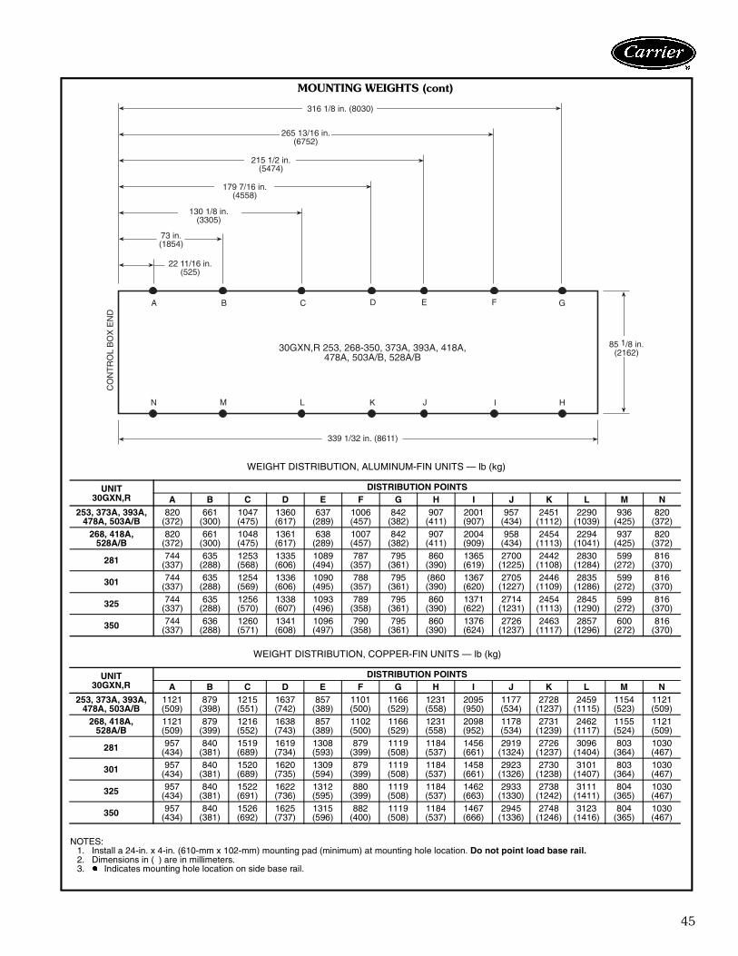
316 1/8 in. (8030)
265 13/16 in.(6752)
215 1/2 in.(5474)
179 7/16 in.(4558)
130 1/8 in.(3305)
73 in.(1854)
85 1/8 in.(2162)30GXN,R 253, 268-350, 373A, 393A, 418A,
478A, 503A/B, 528A/B
A B C D E F G
N M L K J I H
CO
NT
RO
LB
OX
EN
D
22 11/16 in.(525)
339 1/32 in. (8611)
WEIGHT DISTRIBUTION, ALUMINUM-FIN UNITS — lb (kg)
UNIT30GXN,R
DISTRIBUTION POINTSA B C D E F G H I J K L M N
253, 373A, 393A,478A, 503A/B
820(372)
661(300)
1047(475)
1360(617)
637(289)
1006(457)
842(382)
907(411)
2001(907)
957(434)
2451(1112)
2290(1039)
936(425)
820(372)
268, 418A,528A/B
820(372)
661(300)
1048(475)
1361(617)
638(289)
1007(457)
842(382)
907(411)
2004(909)
958(434)
2454(1113)
2294(1041)
937(425)
820(372)
281 744(337)
635(288)
1253(568)
1335(606)
1089(494)
787(357)
795(361)
860(390)
1365(619)
2700(1225)
2442(1108)
2830(1284)
599(272)
816(370)
301 744(337)
635(288)
1254(569)
1336(606)
1090(495)
788(357)
795(361)
(860(390)
1367(620)
2705(1227)
2446(1109)
2835(1286)
599(272)
816(370)
325 744(337)
635(288)
1256(570)
1338(607)
1093(496)
789(358)
795(361)
860(390)
1371(622)
2714(1231)
2454(1113)
2845(1290)
599(272)
816(370)
350 744(337)
636(288)
1260(571)
1341(608)
1096(497)
790(358)
795(361)
860(390)
1376(624)
2726(1237)
2463(1117)
2857(1296)
600(272)
816(370)
WEIGHT DISTRIBUTION, COPPER-FIN UNITS — lb (kg)
UNIT30GXN,R
DISTRIBUTION POINTSA B C D E F G H I J K L M N
253, 373A, 393A,478A, 503A/B
1121(509)
879(398)
1215(551)
1637(742)
857(389)
1101(500)
1166(529)
1231(558)
2095(950)
1177(534)
2728(1237)
2459(1115)
1154(523)
1121(509)
268, 418A,528A/B
1121(509)
879(399)
1216(552)
1638(743)
857(389)
1102(500)
1166(529)
1231(558)
2098(952)
1178(534)
2731(1239)
2462(1117)
1155(524)
1121(509)
281 957(434)
840(381)
1519(689)
1619(734)
1308(593)
879(399)
1119(508)
1184(537)
1456(661)
2919(1324)
2726(1237)
3096(1404)
803(364)
1030(467)
301 957(434)
840(381)
1520(689)
1620(735)
1309(594)
879(399)
1119(508)
1184(537)
1458(661)
2923(1326)
2730(1238)
3101(1407)
803(364)
1030(467)
325 957(434)
840(381)
1522(691)
1622(736)
1312(595)
880(399)
1119(508)
1184(537)
1462(663)
2933(1330)
2738(1242)
3111(1411)
804(365)
1030(467)
350 957(434)
840(381)
1526(692)
1625(737)
1315(596)
882(400)
1119(508)
1184(537)
1467(666)
2945(1336)
2748(1246)
3123(1416)
804(365)
1030(467)
NOTES:1. Install a 24-in. x 4-in. (610-mm x 102-mm) mounting pad (minimum) at mounting hole location. Do not point load base rail.2. Dimensions in ( ) are in millimeters.3. � Indicates mounting hole location on side base rail.
MOUNTING WEIGHTS (cont)

46
Carrier’s electronic catalog chiller selection program pro-vides quick, easy selection of Carrier chillers. The programconsiders specific temperature, fluid, and flow require-ments and other factors, such as fouling and altitude cor-rection. To select a 30GXN,R chiller, use the electroniccatalog or follow one of the procedures below.
SI (50 Hz)I Determine unit size and operating conditions
required to meet given capacity at givenconditions.Given: Capacity. . . . . . . . . . . . . . . . . . . . . . . . . 360 kWLeaving Chilled Water Temp (LCWT) . . . . . . . 6 CCooler Water Temp Rise . . . . . . . . . . . . . . . .6° CCondenser Entering Water Temp . . . . . . . . . 35 CFouling Factor (Cooler) . . . . . . . . . . . . .0.000018NOTE: For other than 6° C temperature rise, datacorrections must be made using the chiller programin the electronic catalog.
II From Cooling Capacity table on page 49 andpressure drop curves on page 56, determineoperating data for selected unit.Unit . . . . . . . . . . . . . . . . . . . . . . . . . 30GXN115Capacity. . . . . . . . . . . . . . . . . . . . . . . .363.7 kWCompressor Motor Power Input . . . . . . .130.7 kWCooler Water Flow . . . . . . . . . . . . . . . . 15.6 L/sCooler Pressure Drop . . . . . . . . . . . . . . 32.2 kPa
ENGLISH (50 Hz)I Determine 30GXN,R unit size and operating
conditions required to meet given capacity atgiven conditions. Given:Capacity. . . . . . . . . . . . . . . . . . . . . . . . 105 TonsLeaving Chilled Water Temp (LCWT) . . . . . . .44 FCooler Water Temp Rise . . . . . . . . . . . . . . . 10° FCondenser Entering Air Temp . . . . . . . . . . . .95 FFouling Factor (Cooler) . . . . . . . . . . . . . .0.00010NOTE: For other than 10° F temperature rise, datacorrections must be made using the chiller programin the electronic catalog. On some units, a changeof controls is also necessary.
II From Cooling Capacities table on page 47and pressure drop curves on page 56, deter-mine operating data for selected unit.Unit . . . . . . . . . . . . . . . . . . . . . . . . . 30GXN115Capacity. . . . . . . . . . . . . . . . . . . . . . . 105.4 tonsPower Input . . . . . . . . . . . . . . . . . . . . .131.7 kWCooler Water Flow . . . . . . . . . . . . . . . 252.7 gpmCooler Pressure Drop . . . . . . . . . .13.8 ft of water
Selection procedure (with example)

47
50 Hz ENGLISH STANDARD UNITS
See Legend on page 53.
LCWT(F)
UNITSIZE
30GXN,R
CONDENSER ENTERING AIR TEMPERATURE (F)85 95 105 115 125
Cap.Tons
InputkW
CoolerFlowRate
(Gpm)
Cap.Tons
InputkW
CoolerFlowRate
(Gpm)
Cap.Tons
InputkW
CoolerFlowRate
(Gpm)
Cap.Tons
InputkW
CoolerFlowRate
(Gpm)
Cap.Tons
InputkW
CoolerFlowRate
(Gpm)
40.00
080 75.3 83.8 180.4 69.3 88.5 165.9 63.1 93.7 151.0 57.1 100.7 136.6 51.5 108.6 123.2090 83.1 96.1 198.8 76.4 101.2 182.9 69.5 107.9 166.4 63.1 116.0 151.1 56.5 123.2 135.3106 95.4 107.2 228.3 87.9 113.0 210.5 80.1 120.4 191.7 72.6 129.0 173.7 65.6 137.9 157.1115 103.4 118.1 247.6 98.5 128.5 235.9 93.4 140.9 223.5 88.2 155.1 211.1 62.8 136.2 150.3125 112.0 129.6 268.2 106.0 140.8 253.8 100.7 154.2 241.1 95.0 170.4 227.4 65.8 153.0 157.5135 122.1 139.4 292.4 115.7 151.2 277.0 109.8 166.0 262.8 103.5 183.2 247.8 56.0 136.8 133.9150 132.9 153.3 318.1 122.3 160.6 292.9 112.0 171.3 268.0 102.1 183.5 244.4 92.8 195.4 222.1160 148.3 172.3 355.0 140.7 186.6 336.8 133.8 203.9 320.2 126.0 224.4 301.6 76.5 178.6 183.1175 157.3 187.0 376.5 150.2 202.5 359.6 142.2 220.6 340.3 134.0 241.5 320.8 86.1 196.8 206.2205 181.8 216.8 435.1 172.6 235.5 413.1 163.4 257.0 391.1 153.8 283.1 368.1 98.6 208.5 236.0220 197.9 226.6 474.6 184.5 243.2 442.8 172.0 262.6 413.0 159.5 287.1 382.5 124.1 277.4 298.0225 202.4 239.1 484.5 192.6 259.7 461.0 182.0 283.9 435.7 170.7 311.6 408.6 108.4 224.6 259.4240 219.7 249.3 526.8 208.4 271.2 499.4 197.6 296.4 473.8 186.3 327.4 447.1 130.3 290.1 312.4250 222.4 269.7 532.4 212.2 291.9 508.0 200.8 319.1 480.8 188.9 349.6 452.1 110.7 226.8 265.0264 237.0 283.0 567.3 226.3 306.7 541.7 213.6 335.3 511.4 200.3 366.9 479.5 112.5 227.4 269.3275 246.8 279.8 592.2 233.7 303.7 560.6 221.7 332.6 531.6 209.0 367.6 500.7 112.5 274.1 269.7281 260.8 299.9 624.3 247.2 326.5 591.8 235.0 355.5 562.7 221.7 391.9 530.8 207.5 432.9 496.7300 275.5 313.1 660.1 261.0 340.0 626.0 248.3 371.6 595.7 234.1 410.2 561.7 135.0 316.6 323.9301 282.1 325.6 675.4 266.6 354.1 638.2 254.0 386.0 608.1 239.2 425.4 572.6 211.9 469.3 507.4320 304.1 347.0 730.2 288.2 376.4 691.1 274.3 410.9 657.3 258.7 451.8 620.5 157.6 358.8 377.9325 302.8 363.2 724.7 287.9 393.6 689.1 273.5 430.7 654.7 257.8 473.5 617.1 151.1 324.3 361.8345 322.1 377.3 772.1 308.1 408.5 738.4 291.3 444.6 698.8 275.2 486.8 659.5 178.1 395.5 427.5350 325.8 403.1 779.8 311.9 437.5 746.5 294.3 478.3 704.6 276.3 525.4 661.3 162.9 349.3 389.9365 351.1 412.8 841.6 333.8 447.0 801.6 316.7 488.8 759.0 298.3 536.2 715.7 170.4 366.0 409.2395 365.5 425.8 875.9 347.6 461.3 833.6 329.5 504.7 789.7 309.7 553.4 743.7 172.3 366.4 413.7410 395.3 461.2 948.4 375.1 500.9 899.3 355.5 546.2 852.2 332.1 599.3 797.4 214.4 436.7 514.0440 416.4 483.8 998.9 395.5 525.3 948.9 374.5 573.2 897.7 349.4 627.8 837.7 224.4 452.9 538.3470 436.5 515.1 1046.6 415.1 558.5 995.7 393.3 608.5 943.5 369.6 667.5 885.8 227.0 454.8 544.3495 456.8 545.4 1094.8 435.0 590.7 1043.8 412.5 643.9 989.7 388.1 705.7 929.9 229.3 457.1 550.2520 486.1 571.6 1165.5 463.2 619.8 1110.4 438.4 676.0 1050.4 409.1 738.5 981.6 233.2 457.9 559.5
44.00
080 81.3 87.4 195.0 75.3 92.1 180.4 68.5 97.0 164.3 61.9 103.6 148.3 55.9 111.6 134.0090 89.7 100.4 215.1 82.8 105.5 198.5 75.5 111.8 180.9 68.3 119.4 163.8 58.3 124.7 139.9106 103.6 111.7 248.3 95.6 117.5 229.1 87.3 124.6 209.2 79.2 132.8 189.8 67.0 138.4 160.5115 110.6 121.0 265.1 105.4 131.7 252.7 99.7 143.7 239.0 94.2 157.7 225.8 67.3 138.5 161.3125 119.8 132.9 287.1 113.3 144.9 271.6 107.4 157.4 257.6 101.4 173.4 243.1 68.2 154.2 163.5135 131.2 142.7 314.6 123.7 155.4 296.5 117.4 168.8 281.5 110.7 186.2 265.5 60.1 138.4 144.0150 144.3 159.9 345.9 133.5 167.5 320.1 122.3 177.1 293.1 111.5 188.8 267.4 101.1 201.6 242.4160 159.2 176.2 381.5 150.2 191.6 360.1 143.0 207.9 342.9 134.8 228.4 323.2 82.0 180.6 196.7175 167.9 192.1 402.5 160.7 207.7 385.3 151.7 225.8 363.7 142.3 245.7 341.1 92.5 199.4 221.7205 194.7 222.7 466.7 184.5 242.0 442.2 174.6 262.6 418.5 164.3 287.8 393.8 105.9 211.2 253.9220 212.8 234.7 510.8 198.9 251.8 477.8 185.1 270.3 444.6 170.0 292.7 408.8 128.8 280.5 308.3225 216.8 246.0 519.7 205.3 266.8 492.2 194.5 290.5 466.3 179.2 316.2 429.5 116.2 228.3 278.6240 234.5 256.0 563.3 223.1 278.8 535.6 211.1 303.3 506.5 196.6 331.6 472.0 136.9 294.3 328.7250 238.2 277.7 570.9 225.9 300.6 541.6 214.4 326.7 514.0 200.4 356.0 480.4 118.8 230.5 284.9264 254.0 291.0 608.8 240.8 315.2 577.3 228.3 343.0 547.4 213.9 374.3 512.8 120.9 230.8 289.8275 264.5 287.0 635.9 250.4 312.2 601.5 237.4 339.5 570.1 222.2 372.7 533.2 121.1 278.2 290.9281 277.5 308.1 665.3 265.5 334.6 636.5 250.7 364.8 601.0 237.4 399.5 569.0 218.4 438.1 523.5300 294.7 321.5 708.0 279.3 349.2 670.2 264.9 379.7 636.8 250.3 416.8 601.2 145.2 322.1 349.0301 301.0 334.3 721.6 285.5 363.5 684.4 271.1 395.3 649.8 255.8 434.2 613.2 212.1 469.3 508.4320 325.2 355.5 780.4 308.2 386.3 739.4 292.8 419.4 703.2 276.5 459.8 663.3 169.4 365.9 407.4325 324.2 372.6 777.1 306.6 404.5 735.0 292.0 439.6 700.1 275.2 482.9 659.7 162.3 329.6 389.0345 343.2 387.4 824.5 328.8 418.9 789.1 311.3 455.1 747.0 288.5 492.2 692.2 191.5 402.9 459.2350 348.3 415.0 834.9 331.6 449.6 794.9 314.0 490.2 752.8 287.5 532.7 689.3 174.5 354.1 418.4365 376.0 424.2 902.5 355.5 459.9 853.5 338.1 499.3 812.6 309.0 541.7 742.5 183.1 370.5 440.1395 391.6 437.1 940.4 370.1 473.8 888.2 352.0 515.5 845.7 320.8 558.8 771.4 185.2 370.7 445.3410 422.6 473.7 1014.9 400.3 514.4 961.7 379.5 558.4 910.9 344.8 605.1 828.0 226.4 442.3 543.5440 444.9 497.4 1067.4 421.7 539.3 1012.7 399.7 586.7 960.2 360.1 633.3 862.5 237.2 459.8 569.6470 466.7 529.3 1120.1 441.9 573.8 1062.2 419.7 623.0 1007.9 379.6 672.1 911.4 243.6 463.7 585.2495 488.4 561.3 1172.6 462.8 607.6 1110.8 439.8 659.1 1056.3 401.3 712.5 963.3 246.3 465.7 591.7520 520.2 587.4 1250.0 492.5 636.2 1182.4 468.0 692.0 1123.2 424.5 746.0 1019.0 250.7 466.4 602.2
Performance data

48
50 Hz ENGLISH STANDARD UNITS (cont)
See Legend on page 53.
LCWT(F)
UNITSIZE
30GXN,R
CONDENSER ENTERING AIR TEMPERATURE (F)85 95 105 115 125
Cap.Tons
InputkW
CoolerFlowRate
(Gpm)
Cap.Tons
InputkW
CoolerFlowRate
(Gpm)
Cap.Tons
InputkW
CoolerFlowRate
(Gpm)
Cap.Tons
InputkW
CoolerFlowRate
(Gpm)
Cap.Tons
InputkW
CoolerFlowRate
(Gpm)
48.00
080 87.6 91.2 210.2 81.2 96.1 194.9 74.3 101.1 178.4 67.2 107.1 161.3 60.5 114.6 145.2090 96.8 105.0 232.4 89.5 110.3 214.7 81.7 116.4 196.0 74.0 123.6 177.7 60.3 125.9 144.7106 112.0 116.5 268.7 103.7 122.3 248.9 95.2 128.8 228.4 86.2 136.7 207.0 69.3 139.6 166.2115 117.9 124.1 282.8 112.2 135.4 269.3 106.5 146.8 255.6 97.6 159.4 234.2 71.9 141.3 172.6125 127.5 136.4 305.9 121.1 148.7 290.6 114.4 161.2 274.6 104.2 174.5 250.2 70.7 156.3 169.7135 139.7 146.4 335.3 132.6 159.5 318.2 125.3 172.9 300.6 116.2 188.3 278.9 64.6 142.3 155.1150 156.3 166.8 375.2 145.3 174.6 348.6 133.3 183.1 319.9 121.3 194.6 291.1 103.5 203.0 248.3160 169.4 181.0 406.6 161.0 196.6 386.3 152.4 212.9 365.7 144.0 232.4 345.5 88.0 185.7 211.2175 178.9 197.2 429.3 171.1 213.2 410.6 162.3 231.1 389.4 147.4 248.6 353.7 99.5 203.7 238.9205 207.3 228.8 497.5 197.0 248.3 472.9 186.3 269.4 447.1 170.8 290.5 409.8 113.3 214.8 272.0220 227.2 242.8 546.2 213.9 260.3 513.9 198.9 279.2 478.7 178.2 297.5 428.3 132.5 283.2 318.3225 231.5 252.9 555.7 218.8 274.2 525.2 207.4 297.7 497.7 181.2 317.3 434.8 120.8 231.2 289.9240 249.2 262.8 599.2 237.8 286.1 571.6 224.9 310.5 540.5 203.2 334.5 487.9 142.9 297.7 343.7250 254.4 285.6 610.6 240.1 309.2 576.2 228.5 334.3 548.3 200.5 356.1 481.3 127.4 235.3 305.6264 271.5 298.7 651.5 255.7 323.5 613.8 243.6 350.8 584.7 211.8 372.8 508.4 129.7 235.4 311.4275 281.8 294.0 677.0 267.9 320.3 643.9 253.1 347.4 608.5 232.4 376.6 558.4 130.7 284.7 314.6281 295.0 315.8 707.9 284.3 342.7 682.2 267.3 373.8 641.6 253.5 407.5 608.4 218.5 438.1 524.4300 313.8 329.6 753.8 298.6 358.1 718.4 282.2 388.0 677.8 264.7 427.4 636.1 156.6 329.7 376.8301 319.6 343.5 767.1 305.6 372.7 733.3 288.3 405.6 691.9 272.8 442.1 654.7 212.2 469.4 509.2320 345.7 365.1 831.0 329.5 396.0 793.0 311.4 429.4 749.2 292.4 467.0 702.8 181.3 374.0 435.9325 345.6 382.6 829.4 327.1 415.7 785.1 310.7 450.3 745.8 293.1 491.9 703.4 173.9 337.4 417.3345 365.1 397.4 876.8 349.4 430.1 839.5 332.1 466.0 799.5 298.4 499.6 717.2 204.6 411.5 492.4350 371.7 426.4 892.0 351.7 461.9 844.1 334.4 501.4 802.6 287.7 532.7 690.5 186.8 363.0 448.4365 400.7 435.8 963.4 379.0 473.1 910.7 359.6 511.6 863.6 315.9 544.5 760.0 196.1 391.3 471.5395 417.9 448.8 1004.6 394.6 487.0 948.8 374.6 527.5 900.0 327.9 561.7 788.7 198.7 388.0 477.6410 449.3 487.0 1079.1 426.8 528.2 1025.6 403.4 582.5 969.5 351.8 607.8 845.8 235.1 446.7 565.2440 474.0 511.2 1138.8 449.1 554.0 1078.4 424.8 612.7 1020.4 362.5 634.5 870.5 243.1 463.4 584.3470 497.1 544.6 1194.5 470.6 589.9 1130.6 445.8 648.2 1070.5 383.7 674.7 921.7 256.2 496.8 615.6495 520.1 577.8 1250.0 492.2 625.1 1182.5 466.9 688.0 1121.8 403.9 714.3 970.7 261.6 502.4 629.8520 554.4 603.9 1331.8 523.9 653.8 1259.4 497.1 722.9 1194.4 427.3 748.4 1026.7 266.7 495.2 641.2
Performance data (cont)

49
50 Hz SI STANDARD UNITS
See Legend on page 53.
LCWT(C)
UNITSIZE
30GXN,R
CONDENSER ENTERING AIR TEMPERATURE (C)30 35 40 45 50
Cap.kW
InputkW
CoolerFlowRate(l/s)
Cap.kW
InputkW
CoolerFlowRate(l/s)
Cap.kW
InputkW
CoolerFlowRate(l/s)
Cap.kW
InputkW
CoolerFlowRate(l/s)
Cap.kW
InputkW
CoolerFlowRate(l/s)
5.00
080 268.1 85.2 11.5 249.1 89.4 10.7 229.1 93.8 9.8 208.5 99.9 8.9 190.8 107.0 8.2090 295.5 97.7 12.7 274.2 102.2 11.8 251.7 108.1 10.8 230.8 115.1 9.9 211.4 122.9 9.1106 340.1 108.7 14.6 315.7 114.0 13.6 290.1 120.7 12.5 266.0 128.3 11.4 242.9 136.6 10.4115 368.2 119.8 15.8 352.6 129.3 15.1 335.7 140.2 14.4 319.2 152.6 13.7 230.1 133.1 9.9125 398.7 131.5 17.1 379.0 141.7 16.3 362.0 153.4 15.5 343.8 167.8 14.8 251.6 148.7 10.8135 434.9 141.4 18.7 413.8 152.3 17.8 394.9 164.9 17.0 375.0 180.3 16.1 260.2 164.5 11.2150 473.9 155.6 20.3 440.3 162.3 18.9 406.1 171.6 17.4 374.4 182.3 16.1 343.8 193.6 14.8160 528.1 174.6 22.7 502.9 187.8 21.6 481.2 202.8 20.7 456.5 221.0 19.6 408.2 240.8 17.5175 559.9 189.6 24.0 537.5 203.7 23.1 511.1 219.9 21.9 485.5 237.7 20.8 316.1 192.3 13.6205 647.1 220.0 27.8 617.3 237.0 26.5 587.5 256.0 25.2 556.7 278.6 23.9 360.5 203.7 15.5220 704.5 230.1 30.3 661.4 245.1 28.4 620.9 261.9 26.7 580.7 283.4 25.0 469.1 273.1 20.2225 720.1 243.0 30.9 688.6 261.3 29.6 654.9 282.9 28.1 618.6 307.0 26.6 396.4 220.1 17.0240 781.9 253.4 33.6 745.3 273.6 32.0 710.0 295.6 30.6 674.8 322.5 29.0 490.1 284.0 21.1250 791.3 273.8 34.0 758.2 294.0 32.5 722.4 318.1 31.0 683.8 344.5 29.4 405.0 222.0 17.4264 843.3 287.3 36.2 808.5 308.9 34.7 768.7 334.1 33.0 725.8 361.3 31.2 411.9 222.4 17.7275 879.4 283.8 37.8 836.4 306.0 36.0 797.9 330.9 34.3 757.4 361.5 32.5 523.5 331.4 22.5281 928.6 304.2 39.9 885.3 328.6 38.0 844.3 354.9 36.2 803.2 386.1 34.5 757.8 421.4 32.5300 980.6 317.9 42.1 933.7 342.2 40.2 892.3 370.1 38.4 847.7 403.9 36.5 663.7 405.6 28.6301 1004.1 330.5 43.1 953.1 356.5 40.9 913.4 384.4 39.2 866.5 419.2 37.2 817.3 457.7 35.1320 1082.4 352.0 46.6 1030.4 379.2 44.3 985.7 409.2 42.4 936.6 445.2 40.3 818.5 482.3 35.2325 1077.4 368.4 46.2 1028.8 396.3 44.2 983.5 428.8 42.2 933.3 466.6 40.1 808.4 508.7 34.7345 1146.2 382.8 49.3 1101.9 411.0 47.4 1047.6 443.5 45.1 995.8 479.6 42.8 654.7 387.1 28.2350 1158.7 409.2 49.7 1114.3 440.3 47.8 1058.8 477.1 45.5 1000.2 516.7 42.9 596.2 341.5 25.6365 1249.1 419.2 53.7 1192.6 450.4 51.3 1138.8 487.0 48.9 1079.8 529.2 46.5 684.0 389.7 29.4395 1300.7 432.1 55.9 1242.1 464.6 53.4 1185.4 502.3 51.0 1121.8 546.0 48.2 691.2 389.8 29.7410 1406.6 468.1 60.5 1340.7 504.4 57.7 1278.8 543.8 54.9 1210.7 591.2 52.1 784.5 427.5 33.7440 1481.4 491.0 63.7 1413.3 528.7 60.8 1347.1 571.2 57.9 1273.5 620.1 54.7 821.6 443.9 35.3470 1552.8 522.8 66.8 1483.3 562.0 63.8 1414.5 606.8 60.9 1338.2 658.5 57.5 830.4 446.1 35.7495 1624.9 553.8 69.8 1554.2 594.6 66.9 1483.3 641.7 63.8 1404.5 696.0 60.4 839.4 447.7 36.1520 1729.1 580.2 74.4 1654.8 623.6 71.1 1576.9 673.8 67.8 1489.6 729.9 64.1 853.8 448.2 36.7
6.00
080 277.5 86.8 11.9 258.4 91.0 11.1 237.4 95.4 10.2 216.6 101.2 9.3 198.1 108.2 8.5090 306.3 99.6 13.2 284.3 104.1 12.2 261.4 109.9 11.2 239.3 116.7 10.3 219.1 124.6 9.4106 352.8 110.8 15.2 328.0 116.1 14.1 301.9 122.5 13.0 276.9 129.9 11.9 252.7 138.1 10.9115 379.3 121.2 16.3 363.7 130.7 15.6 345.7 141.6 14.8 328.8 154.0 14.1 237.5 134.3 10.2125 411.1 133.0 17.7 390.7 143.5 16.8 372.7 154.9 16.0 354.1 169.1 15.2 257.3 149.8 11.0135 449.2 142.9 19.3 426.5 154.1 18.3 407.1 166.2 17.5 386.6 181.6 16.6 263.8 165.1 11.3150 491.4 158.5 21.1 457.7 165.4 19.7 422.5 174.2 18.1 389.2 184.7 16.7 357.0 196.1 15.3160 545.5 176.3 23.4 517.9 189.9 22.2 495.9 204.6 21.3 470.7 222.6 20.2 410.8 240.9 17.6175 576.5 192.1 24.8 554.2 206.0 23.8 526.2 222.0 22.6 500.5 239.8 21.5 326.7 193.7 14.0205 667.8 222.7 28.7 635.5 240.0 27.3 605.5 258.5 26.0 573.7 280.9 24.6 372.3 205.1 16.0220 728.5 233.7 31.3 684.0 249.1 29.4 642.1 265.6 27.7 600.0 286.3 25.9 482.1 274.9 20.7225 742.7 245.9 31.9 708.7 264.5 30.4 674.9 285.8 29.0 637.2 310.2 27.4 409.3 221.8 17.6240 805.5 256.2 34.7 769.0 276.7 33.1 731.8 298.4 31.5 695.3 324.9 29.9 501.7 285.3 21.6250 816.0 277.5 35.1 779.8 297.9 33.5 743.9 321.4 32.0 704.2 348.2 30.2 418.2 223.7 18.0264 870.0 290.9 37.4 831.5 312.6 35.7 792.0 337.7 34.0 747.8 365.3 32.1 425.5 224.0 18.3275 907.7 286.9 39.1 862.3 309.9 37.1 822.7 334.4 35.4 781.5 364.5 33.6 533.7 332.1 23.0281 954.9 308.0 41.0 914.2 332.3 39.3 869.1 359.1 37.3 828.2 389.5 35.6 781.7 425.1 33.6300 1010.9 321.6 43.5 962.6 346.4 41.5 918.8 373.9 39.5 874.0 406.9 37.6 672.5 405.9 28.9301 1035.5 334.0 44.5 983.3 360.6 42.2 940.1 388.8 40.4 893.0 423.0 38.4 835.1 460.4 35.9320 1115.6 355.9 48.0 1061.8 383.4 45.7 1015.2 413.3 43.7 965.1 449.3 41.5 822.6 481.9 35.3325 1111.1 372.8 47.7 1058.4 401.2 45.5 1012.7 432.8 43.5 961.1 471.3 41.3 812.8 508.2 34.9345 1179.2 387.2 50.8 1134.6 415.7 48.8 1079.3 448.2 46.5 1025.4 484.0 44.1 676.6 390.6 29.1350 1193.9 414.7 51.3 1145.3 445.8 49.2 1090.1 482.2 46.8 1029.8 521.7 44.2 615.2 343.6 26.4365 1288.3 424.2 55.4 1227.1 456.2 52.8 1173.0 491.3 50.5 1112.2 533.9 47.8 701.0 392.2 30.2395 1341.7 437.2 57.7 1277.9 470.2 54.9 1221.0 507.5 52.5 1155.9 551.4 49.7 709.1 392.2 30.5410 1449.9 473.7 62.4 1380.6 510.1 59.4 1316.1 550.0 56.6 1238.7 594.8 53.3 810.1 430.6 34.9440 1526.5 497.0 65.7 1455.0 535.1 62.6 1386.9 577.4 59.7 1303.6 624.0 56.0 848.3 447.7 36.5470 1600.3 529.2 68.8 1525.2 569.2 65.7 1456.5 613.1 62.7 1377.7 664.7 59.3 857.5 450.0 36.9495 1674.6 560.8 72.0 1597.9 602.5 68.7 1526.6 648.7 65.7 1445.8 702.5 62.2 866.8 452.0 37.3520 1782.7 587.6 76.7 1700.9 631.5 73.2 1624.3 681.0 69.8 1534.4 736.8 66.0 881.7 452.3 38.0
7.00
080 287.2 88.5 12.3 267.7 92.7 11.5 246.6 97.0 10.6 225.0 102.7 9.7 205.5 109.6 8.8090 316.7 101.6 13.6 294.6 106.2 12.7 271.0 111.8 11.6 248.1 118.5 10.7 224.4 125.6 9.6106 365.5 112.9 15.7 340.4 118.3 14.6 314.2 124.4 13.5 287.9 131.5 12.4 262.3 139.8 11.3115 390.9 122.4 16.8 374.2 132.4 16.1 356.3 142.8 15.3 338.5 155.3 14.5 245.2 135.6 10.5125 423.3 134.6 18.2 402.5 145.4 17.3 383.5 156.5 16.5 364.2 170.8 15.7 263.2 151.4 11.3135 463.6 144.5 19.9 439.3 156.1 18.9 419.3 167.6 18.0 398.3 183.0 17.1 267.6 166.1 11.5150 509.9 161.6 21.9 476.3 168.6 20.5 439.6 176.8 18.9 404.3 187.2 17.4 371.7 198.5 16.0160 562.5 178.4 24.2 533.8 192.5 22.9 510.4 206.9 21.9 484.9 225.0 20.8 409.4 241.1 17.6175 593.6 194.4 25.5 571.0 208.3 24.5 542.2 224.5 23.3 515.4 242.4 22.2 337.8 195.1 14.5205 688.2 225.3 29.6 655.3 243.0 28.2 623.8 261.5 26.8 590.9 283.6 25.4 384.6 206.3 16.5220 751.4 237.5 32.3 707.8 253.0 30.5 663.1 269.6 28.6 619.9 289.8 26.7 494.0 277.5 21.3225 765.9 249.0 32.9 728.9 268.0 31.3 695.3 288.9 29.9 656.5 313.3 28.2 422.4 223.4 18.2240 829.1 259.2 35.7 792.4 279.9 34.1 753.7 301.7 32.4 716.4 327.3 30.7 513.5 287.3 22.1250 841.2 281.2 36.2 801.8 301.8 34.5 765.9 324.9 32.9 724.8 352.0 31.2 431.7 225.5 18.6264 897.0 294.5 38.6 854.8 316.4 36.7 816.0 341.2 35.1 770.4 369.1 33.1 439.4 225.6 18.9275 935.2 290.4 40.3 889.5 313.4 38.3 847.8 337.4 36.5 805.6 367.2 34.7 542.7 333.1 23.4281 981.8 311.7 42.2 943.8 335.9 40.6 894.5 362.9 38.4 853.8 392.8 36.7 805.9 428.9 34.6300 1042.0 325.2 44.9 992.4 350.6 42.7 945.8 377.5 40.7 899.8 410.2 38.7 675.3 406.7 29.0301 1064.8 338.3 45.8 1014.6 364.8 43.6 967.1 393.4 41.6 919.7 427.1 39.5 846.5 461.5 36.4320 1149.3 360.0 49.5 1094.9 387.7 47.1 1044.6 417.2 45.0 993.7 452.8 42.8 820.2 482.0 35.3325 1145.5 377.1 49.2 1088.3 405.9 46.8 1042.7 436.9 44.8 989.5 475.3 42.5 810.1 508.5 34.8345 1213.1 391.9 52.2 1167.2 420.5 50.2 1111.9 452.8 47.8 1047.9 487.1 45.2 699.3 394.2 30.1350 1229.8 420.0 52.9 1176.8 451.3 50.6 1122.0 487.4 48.2 1059.7 527.5 45.5 634.4 346.8 27.3365 1328.3 429.3 57.2 1262.3 461.9 54.3 1206.8 496.6 52.0 1144.3 539.0 49.3 718.9 395.4 31.0395 1383.5 442.3 59.6 1314.1 475.6 56.5 1257.1 512.1 54.2 1182.8 554.7 50.9 726.5 395.7 31.3410 1493.5 479.6 64.3 1421.5 516.6 61.2 1354.6 556.0 58.3 1267.0 598.7 54.5 835.4 434.5 36.0440 1572.0 503.2 67.6 1497.0 541.7 64.4 1427.1 583.9 61.5 1334.0 628.4 57.4 875.5 451.9 37.7470 1648.2 536.0 70.9 1568.7 576.2 67.5 1498.2 620.3 64.5 1403.1 667.7 60.4 884.6 454.6 38.1495 1725.0 568.3 74.2 1643.0 610.6 70.7 1570.1 656.5 67.5 1472.4 706.9 63.3 893.9 456.8 38.5520 1837.1 595.0 79.0 1747.8 639.1 75.2 1671.4 688.6 71.9 1563.5 741.7 67.2 910.3 456.7 39.2
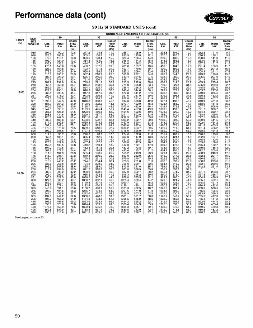
50
50 Hz SI STANDARD UNITS (cont)
See Legend on page 53.
LCWT(C)
UNITSIZE
30GXN,R
CONDENSER ENTERING AIR TEMPERATURE (C)30 35 40 45 50
Cap.kW
InputkW
CoolerFlowRate(l/s)
Cap.kW
InputkW
CoolerFlowRate(l/s)
Cap.kW
InputkW
CoolerFlowRate(l/s)
Cap.kW
InputkW
CoolerFlowRate(l/s)
Cap.kW
InputkW
CoolerFlowRate(l/s)
8.00
080 297.0 90.2 12.8 277.2 94.5 11.9 255.7 98.9 11.0 233.8 104.2 10.1 212.8 111.0 9.1090 328.0 103.6 14.1 305.1 108.3 13.1 280.9 113.8 12.1 257.5 120.3 11.1 226.9 126.1 9.8106 378.9 115.1 16.3 353.6 120.4 15.2 326.4 126.4 14.0 299.3 133.3 12.9 268.8 141.0 11.6115 402.4 124.0 17.3 384.8 134.0 16.5 366.8 144.3 15.8 348.5 156.6 15.0 253.0 136.5 10.9125 435.7 136.2 18.7 414.7 147.2 17.8 394.6 158.2 17.0 375.4 171.6 16.1 267.2 151.7 11.5135 478.1 146.0 20.6 453.7 157.9 19.5 431.8 169.7 18.6 410.0 184.6 17.6 271.4 166.9 11.7150 528.9 164.8 22.7 493.7 171.8 21.2 457.7 179.6 19.7 420.0 189.8 18.1 385.7 201.2 16.6160 579.3 180.5 24.9 550.9 194.5 23.7 525.2 209.4 22.6 499.5 226.8 21.5 408.3 241.1 17.6175 610.9 196.7 26.3 587.4 210.9 25.3 558.9 227.1 24.0 526.7 244.3 22.6 349.3 196.8 15.0205 708.1 228.2 30.4 675.1 245.8 29.0 642.4 264.5 27.6 608.6 286.0 26.2 396.5 207.9 17.0220 774.9 241.2 33.4 731.6 256.7 31.5 685.1 273.8 29.5 634.3 292.0 27.3 501.3 278.6 21.6225 789.7 252.0 34.0 749.8 271.2 32.2 715.9 292.0 30.8 668.1 314.8 28.7 435.9 225.4 18.7240 852.4 262.0 36.7 815.3 283.3 35.1 775.9 305.0 33.4 730.5 329.4 31.5 525.9 289.3 22.7250 866.9 284.7 37.3 824.1 305.7 35.4 788.4 328.3 33.9 746.4 355.5 32.1 445.5 227.6 19.2264 924.6 298.1 39.8 878.3 320.1 37.8 840.4 344.6 36.1 793.4 373.1 34.1 453.7 227.6 19.5275 963.1 293.5 41.4 917.0 317.0 39.5 872.8 341.2 37.6 826.5 369.3 35.6 549.0 335.5 23.7281 1009.3 315.2 43.4 973.6 339.3 41.9 921.0 367.0 39.6 879.3 396.5 37.8 830.3 432.2 35.7300 1072.5 329.0 46.2 1022.2 354.7 44.0 972.8 381.4 41.9 926.2 413.6 39.9 678.4 407.7 29.2301 1093.9 342.5 47.0 1046.3 368.9 45.0 994.6 398.0 42.8 947.4 430.6 40.7 843.9 461.0 36.3320 1181.9 364.3 51.0 1128.0 392.2 48.6 1073.7 422.0 46.3 1023.4 456.2 44.1 818.0 481.8 35.2325 1180.3 381.7 50.8 1120.7 411.0 48.2 1072.4 442.0 46.1 1018.4 479.8 43.8 807.7 508.6 34.7345 1247.5 396.7 53.7 1199.9 425.4 51.7 1145.4 457.6 49.3 1069.9 491.0 46.1 721.7 398.7 31.1350 1266.6 425.0 54.5 1208.6 456.8 52.0 1154.6 492.6 49.6 1073.5 529.9 46.2 654.4 350.7 28.1365 1368.6 434.6 58.9 1299.1 467.7 55.9 1241.1 502.0 53.5 1155.0 540.1 49.8 738.9 399.0 31.8395 1425.9 447.3 61.4 1351.8 481.5 58.2 1292.9 517.7 55.6 1201.1 557.5 51.7 747.1 398.9 32.2410 1535.6 485.6 66.1 1463.9 522.7 63.1 1393.2 562.7 60.0 1283.5 601.5 55.2 860.9 441.5 37.1440 1617.9 509.5 69.6 1539.8 548.2 66.3 1467.9 590.4 63.2 1348.2 630.7 58.0 902.0 464.2 38.8470 1697.4 542.4 73.1 1613.1 583.5 69.4 1540.6 627.4 66.3 1420.9 671.4 61.2 911.3 463.5 39.2495 1775.9 575.3 76.5 1689.1 618.0 72.7 1614.2 663.7 69.5 1491.7 711.2 64.2 921.4 466.2 39.7520 1892.2 601.6 81.4 1797.8 646.8 77.4 1718.0 696.0 74.0 1585.0 745.9 68.2 938.5 464.3 40.4
10.00
080 317.1 93.7 13.6 296.3 98.2 12.8 274.6 102.6 11.8 251.4 107.4 10.8 228.5 113.8 9.8090 350.1 108.1 15.1 326.4 112.9 14.0 302.0 117.9 13.0 276.4 124.1 11.9 232.9 127.1 10.0106 406.2 119.6 17.5 379.9 124.8 16.4 351.2 130.3 15.1 322.5 137.4 13.9 275.9 142.0 11.9115 425.1 127.0 18.3 407.4 137.0 17.5 388.8 147.5 16.7 364.7 159.0 15.7 269.0 138.6 11.6125 459.8 139.5 19.8 440.2 150.4 18.9 417.0 162.1 17.9 389.6 173.6 16.8 275.4 152.7 11.9135 504.2 149.6 21.7 482.4 161.5 20.8 457.2 173.8 19.7 434.1 187.1 18.7 279.9 168.4 12.0150 567.9 171.2 24.4 531.9 178.4 22.9 493.4 185.7 21.2 454.1 195.5 19.5 412.7 205.8 17.8160 611.3 184.9 26.3 585.4 198.9 25.2 555.2 213.9 23.9 529.1 230.2 22.8 408.9 240.9 17.6175 645.7 201.4 27.8 619.8 216.0 26.7 593.0 232.0 25.5 545.0 247.3 23.5 372.3 201.7 16.0205 748.4 233.6 32.2 715.3 251.5 30.8 679.8 270.7 29.3 632.3 288.7 27.2 420.6 212.1 18.1220 816.9 248.2 35.2 774.5 264.4 33.4 726.5 281.0 31.3 663.3 297.2 28.6 508.8 279.8 21.9225 835.5 258.6 36.0 794.3 278.0 34.2 756.0 299.1 32.5 684.4 316.7 29.5 463.1 230.6 19.9240 895.3 267.9 38.6 855.1 289.0 36.9 813.5 311.0 35.1 759.1 333.2 32.7 542.2 291.0 23.4250 918.7 292.0 39.5 871.2 313.8 37.5 831.8 336.5 35.8 756.7 357.1 32.6 0 0 0264 980.3 305.2 42.2 928.9 328.0 40.0 887.0 352.7 38.2 805.4 374.7 34.7 481.1 233.3 20.7275 1009.4 299.3 43.5 966.3 323.3 41.6 916.3 348.2 39.5 860.7 373.4 37.1 557.3 336.7 24.0281 1065.0 322.3 45.8 1030.5 347.3 44.4 979.0 375.3 42.1 929.2 405.5 40.0 864.9 436.9 37.2300 1127.4 336.2 48.7 1080.7 362.1 46.6 1025.4 389.4 44.2 970.5 424.7 41.8 685.1 409.1 29.5301 1153.3 350.7 49.6 1110.4 377.3 47.8 1050.7 407.1 45.2 1002.2 438.7 43.1 845.5 461.4 36.4320 1242.3 372.4 53.5 1192.4 400.3 51.4 1126.1 430.1 48.6 1070.8 479.1 46.2 820.9 482.0 35.4325 1246.2 391.1 53.6 1188.7 420.9 51.2 1131.3 452.5 48.7 1075.9 487.7 46.3 809.5 508.5 34.8345 1308.2 404.6 56.3 1256.7 434.5 54.3 1201.6 474.0 51.8 1094.5 495.2 47.2 755.6 405.5 32.6350 1341.1 435.8 57.7 1272.6 467.6 54.8 1218.9 503.3 52.5 1075.5 530.7 46.3 693.9 359.3 29.9365 1437.1 444.2 62.0 1368.6 478.0 59.0 1301.1 521.7 56.0 1176.2 542.2 50.7 765.5 417.0 33.0395 1507.2 458.2 64.9 1434.3 493.5 61.8 1358.5 566.9 58.5 1222.2 559.5 52.7 775.4 411.2 33.4410 1606.6 495.6 69.2 1533.6 533.4 66.1 1454.2 595.2 62.7 1312.7 604.8 56.5 892.6 444.5 38.5440 1695.1 520.6 73.0 1614.4 559.7 69.5 1530.4 634.3 65.9 1365.3 632.8 58.7 936.9 465.4 40.4470 1776.6 553.9 76.5 1690.4 595.6 72.9 1605.3 665.1 69.1 1433.3 672.8 61.7 949.5 479.8 40.9495 1859.8 587.9 80.1 1768.5 631.4 76.2 1680.5 712.9 72.4 1512.0 713.8 65.1 959.8 483.2 41.3520 1990.6 615.6 85.7 1881.8 659.6 81.1 1791.0 738.7 77.1 1598.6 748.0 68.9 978.2 476.9 42.1
Performance data (cont)
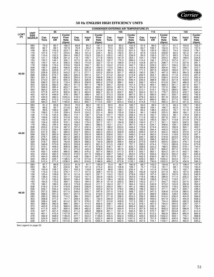
51
50 Hz ENGLISH HIGH EFFICIENCY UNITS
See Legend on page 53.
LCWT(F)
UNITSIZE
30GXN,R
CONDENSER ENTERING AIR TEMPERATURE (F)85 95 105 115 125
Cap.Tons
InputkW
CoolerFlowRate
(Gpm)
Cap.Tons
InputkW
CoolerFlowRate
(Gpm)
Cap.Tons
InputkW
CoolerFlowRate
(Gpm)
Cap.Tons
InputkW
CoolerFlowRate
(Gpm)
Cap.Tons
InputkW
CoolerFlowRate
(Gpm)
40.00
083 75.3 80.7 180.2 69.8 85.3 167.1 63.9 90.2 152.9 57.5 96.0 137.7 51.7 103.6 123.7093 82.7 89.1 197.9 76.9 94.2 184.1 70.5 99.5 168.7 63.7 106.1 152.6 57.5 114.5 137.5108 93.5 103.3 223.7 89.1 113.1 213.4 84.2 123.2 201.5 79.5 135.9 190.2 74.4 150.8 178.1118 101.5 110.7 243.0 98.2 121.2 235.1 92.5 132.5 221.4 87.6 144.9 209.8 82.5 161.2 197.4128 110.4 122.2 264.4 106.2 133.3 254.3 100.2 145.2 239.9 95.0 159.3 227.5 89.5 176.6 214.2138 121.7 136.8 291.2 116.1 149.1 277.8 109.9 161.9 263.1 104.1 178.6 249.2 98.0 198.0 234.6153 133.7 149.1 320.1 127.2 161.6 304.5 120.7 175.3 289.0 114.2 192.1 273.3 107.0 211.1 256.2163 144.7 161.4 346.5 139.0 174.9 332.7 131.5 189.9 314.9 124.8 207.0 298.7 117.4 227.6 281.1178 158.6 179.4 379.6 150.8 193.7 361.0 143.2 210.0 342.7 135.2 229.2 323.7 126.5 251.0 302.8208 190.7 208.5 456.6 183.4 226.9 439.0 173.5 246.4 415.4 164.8 269.9 394.6 155.7 298.7 372.7228 199.4 222.8 477.3 190.4 241.9 455.9 180.7 262.6 432.5 171.2 287.9 409.8 160.9 317.5 385.3253 226.9 255.3 543.2 217.3 277.1 520.2 205.9 301.7 492.8 195.2 330.7 467.3 183.3 364.3 438.8268 236.5 274.7 566.2 226.3 297.4 541.7 214.2 324.0 512.8 202.5 354.7 484.8 111.6 218.9 267.2283 261.3 288.1 626.6 250.0 312.8 599.8 236.5 339.7 567.4 224.4 373.0 538.0 210.9 412.2 505.4303 273.0 301.0 655.3 262.2 326.8 628.8 248.2 354.9 595.4 235.5 388.9 565.3 221.9 429.8 532.2328 299.3 331.8 718.4 285.8 358.8 685.2 270.8 389.1 649.1 256.7 425.4 615.8 240.7 466.9 577.5353 325.6 362.5 780.4 311.0 391.4 746.9 294.7 424.6 707.4 279.3 463.1 669.3 261.7 507.6 627.7373 356.0 395.4 853.7 341.7 429.6 820.1 323.0 467.5 774.3 307.0 513.0 737.0 288.7 567.6 692.1393 364.2 404.4 872.7 348.0 437.5 834.6 329.8 474.4 790.5 313.1 519.1 752.0 289.5 569.1 694.3418 377.8 427.6 905.6 361.3 463.0 865.7 341.9 503.7 820.7 324.0 551.3 776.7 225.3 433.7 540.4453 407.6 449.9 978.1 390.7 488.4 937.3 370.3 530.8 887.5 351.3 580.5 842.1 330.7 640.2 792.6478 435.9 482.5 1045.5 418.5 523.4 1003.8 395.9 569.5 949.9 376.2 623.5 901.8 353.8 688.5 848.3503 464.2 515.3 1112.6 446.1 559.0 1069.0 422.0 609.1 1012.1 401.0 666.5 962.1 377.0 735.6 903.7528 484.0 554.7 1160.6 464.2 600.7 1112.5 439.1 654.4 1052.4 414.8 715.3 995.5 231.0 441.6 554.2
44.00
083 81.3 83.8 194.9 75.6 88.2 181.3 69.5 93.4 166.7 63.0 98.5 151.0 56.3 105.7 135.0093 89.2 92.7 213.8 83.2 97.6 199.3 76.6 103.1 183.7 69.6 109.1 166.7 62.5 117.0 149.9108 99.6 106.0 238.7 95.8 115.9 229.6 90.2 126.7 216.3 85.2 138.5 204.2 76.7 151.9 183.8118 108.2 113.6 259.4 104.9 124.2 251.4 99.9 135.9 239.4 94.1 148.6 225.5 88.6 164.1 212.4128 117.8 125.4 282.4 114.1 136.7 273.6 107.7 149.5 258.3 101.9 162.7 244.3 96.1 179.9 230.3138 129.6 140.5 310.8 125.1 153.0 300.0 117.8 167.0 282.4 111.6 182.0 267.6 105.1 201.8 251.9153 142.5 152.6 341.6 137.0 165.2 328.3 129.0 179.4 309.3 122.5 195.5 293.7 114.8 214.9 275.3163 154.4 165.8 370.1 149.2 179.4 357.7 141.1 194.9 338.3 134.0 211.7 321.1 126.0 232.5 302.1178 169.2 184.4 405.6 162.5 199.0 389.5 153.1 215.7 367.0 145.4 234.7 348.6 136.1 256.8 326.2208 203.2 213.6 487.2 197.2 232.4 472.7 186.2 253.5 446.4 176.6 274.9 423.5 166.9 304.1 400.1228 212.5 229.1 509.3 204.8 248.6 490.8 193.5 270.3 463.8 183.6 294.4 440.0 172.6 324.1 413.9253 241.9 262.1 580.0 233.7 284.2 560.3 220.3 309.9 528.0 209.5 337.9 502.2 196.8 372.6 471.8268 252.3 282.9 604.8 242.3 305.9 580.8 228.6 333.1 548.0 214.6 362.0 514.6 119.8 222.8 287.1283 278.1 295.2 667.2 268.3 320.9 644.4 253.4 349.3 608.7 240.1 380.6 576.8 223.6 418.3 536.8303 290.6 309.2 697.8 280.9 335.9 674.0 266.5 365.4 640.4 252.2 398.2 605.8 237.7 437.5 571.3328 318.7 340.6 764.8 306.8 368.2 735.9 289.8 399.4 695.8 274.9 434.9 659.6 258.0 476.1 619.8353 346.8 372.8 832.9 333.8 402.5 801.0 315.5 436.2 757.1 299.3 474.4 719.3 280.8 518.4 673.8373 379.1 406.0 909.9 366.3 441.6 878.9 346.7 481.1 832.7 328.6 525.2 788.5 309.6 579.1 744.4393 387.8 415.2 931.3 373.6 449.4 896.6 353.5 487.6 848.5 335.3 530.7 806.2 307.2 578.3 737.1418 402.1 439.6 966.0 386.2 476.2 927.4 366.0 517.3 878.1 343.1 562.1 824.2 241.4 442.1 580.1453 434.0 462.5 1042.8 419.0 501.9 1006.4 396.7 546.2 953.0 376.2 594.6 902.9 352.2 652.1 845.9478 464.0 495.8 1113.5 448.1 538.4 1075.0 424.8 585.7 1020.1 402.5 639.0 967.0 379.1 702.4 910.2503 494.2 529.1 1186.5 477.8 574.6 1146.9 452.5 625.8 1085.6 429.2 683.1 1030.2 404.0 751.7 970.6528 515.4 571.2 1238.5 495.2 618.6 1188.9 469.2 672.8 1126.1 438.5 730.6 1052.5 247.8 450.9 595.3
48.00
083 87.7 86.8 210.5 81.6 91.7 195.9 75.4 96.7 180.9 68.7 102.0 164.8 61.5 108.4 147.6093 96.1 96.1 230.6 89.7 101.3 215.2 83.0 106.8 199.1 75.7 112.6 181.7 68.1 119.9 163.4108 105.9 108.7 254.1 102.3 118.8 245.6 96.8 130.0 232.4 91.1 141.6 218.6 79.1 152.7 189.8118 115.3 116.3 276.7 111.7 127.2 268.1 107.6 139.2 258.1 100.8 152.8 241.9 95.0 167.0 228.0128 125.4 128.8 301.0 121.6 140.5 291.7 116.2 153.5 278.8 109.2 167.4 262.0 102.9 183.3 246.9138 138.0 144.5 331.1 133.6 157.4 320.6 126.6 172.0 303.9 119.4 186.9 286.6 111.4 205.2 267.4153 151.5 156.2 363.6 146.4 169.3 351.4 138.4 183.8 332.2 130.9 199.6 314.2 119.0 217.1 285.6163 164.2 170.2 394.1 159.0 184.4 381.6 151.9 200.0 364.5 143.2 217.7 343.7 135.0 237.0 324.1178 180.1 189.5 432.3 173.8 204.8 417.1 164.3 221.7 394.4 155.5 240.9 373.2 145.9 262.8 350.2208 216.2 219.4 518.9 209.8 238.6 503.5 200.5 260.1 481.2 189.0 283.0 453.6 178.5 309.3 428.4228 226.1 235.4 542.6 218.8 255.7 525.0 207.6 278.2 498.2 196.3 302.3 471.1 182.7 329.7 438.4253 257.2 269.2 617.4 249.0 292.7 597.6 237.0 318.5 568.7 223.7 347.5 536.8 210.8 380.5 505.8268 268.2 291.2 643.7 257.5 315.6 618.0 244.8 342.6 587.5 224.4 368.9 538.6 128.0 228.2 307.3283 295.3 302.8 710.2 286.1 329.5 687.5 271.8 358.5 653.5 256.2 389.6 616.0 236.0 424.9 566.9303 308.8 317.2 741.7 299.4 345.1 720.4 285.8 375.6 686.8 269.4 409.0 647.9 253.1 445.9 608.3328 338.4 349.1 814.2 327.3 378.3 787.7 310.6 409.9 747.3 293.1 446.5 704.4 268.8 482.0 646.6353 368.5 382.9 885.1 356.1 414.4 856.5 338.1 448.3 813.2 318.1 487.2 764.5 294.5 526.7 707.7373 402.6 416.9 968.0 390.3 454.3 938.2 372.1 494.8 893.9 350.5 539.1 842.1 330.9 591.1 796.0393 411.9 425.7 990.4 398.9 462.0 959.1 378.8 500.9 910.4 357.9 542.9 859.3 322.8 586.8 775.4418 427.1 451.2 1026.3 411.2 489.8 988.8 391.1 531.4 940.3 361.3 572.7 867.7 254.8 451.1 612.4453 461.1 475.4 1107.8 446.7 516.3 1072.6 425.5 561.8 1022.5 401.6 612.5 965.8 368.4 660.9 884.9478 492.9 508.9 1184.6 477.7 553.4 1148.0 455.5 602.3 1094.2 429.5 655.8 1032.2 403.1 716.1 968.8503 524.9 543.0 1262.2 508.7 591.0 1222.2 485.8 642.9 1167.5 457.8 701.9 1099.5 430.0 766.2 1032.9528 547.4 587.5 1314.8 526.1 637.8 1265.4 501.4 692.0 1205.0 457.9 744.1 1100.1 264.0 462.0 635.2

52
50 Hz SI HIGH EFFICIENCY UNITS
See Legend on page 53.
LCWT(C)
UNITSIZE
30GXN,R
CONDENSER ENTERING AIR TEMPERATURE (C)30 35 40 45 50
Cap.kW
InputkW
CoolerFlowRate(l/s)
Cap.kW
InputkW
CoolerFlowRate(l/s)
Cap.kW
InputkW
CoolerFlowRate(l/s)
Cap.kW
InputkW
CoolerFlowRate(l/s)
Cap.kW
InputkW
CoolerFlowRate(l/s)
5.00
083 268.0 81.9 11.5 250.6 86.0 10.8 231.9 90.5 10.0 211.6 95.3 9.1 191.6 101.6 8.2093 294.4 90.4 12.6 275.6 95.1 11.8 255.5 99.8 11.0 234.1 105.3 10.0 212.9 112.4 9.1108 333.0 104.8 14.3 319.6 113.7 13.7 302.7 123.1 13.0 287.8 133.7 12.4 271.8 146.8 11.7118 361.6 112.5 15.5 351.5 122.0 15.1 333.5 132.2 14.3 317.3 142.9 13.6 301.0 156.8 12.9128 393.6 123.9 16.9 380.7 134.1 16.3 360.7 145.0 15.5 344.0 156.8 14.8 326.4 172.1 14.0138 433.4 138.9 18.6 416.1 150.0 17.9 395.4 161.8 17.0 376.9 175.8 16.2 357.6 192.6 15.3153 476.3 151.1 20.4 455.9 162.4 19.6 433.9 174.9 18.6 413.8 189.3 17.8 391.0 206.0 16.8163 515.8 163.8 22.1 498.3 175.9 21.4 473.1 189.6 20.3 451.9 204.2 19.4 428.5 222.4 18.4178 565.0 181.9 24.3 540.5 195.1 23.2 514.6 209.7 22.1 490.4 226.4 21.1 462.4 245.5 19.8208 679.7 211.6 29.2 657.2 228.2 28.2 624.0 246.1 26.8 596.3 265.6 25.6 567.3 291.1 24.4228 710.3 226.2 30.5 682.4 243.5 29.3 649.4 262.3 27.9 619.8 283.9 26.6 587.4 309.7 25.2253 808.4 259.1 34.7 778.7 278.9 33.4 739.7 301.1 31.8 707.2 325.9 30.4 669.4 356.0 28.7268 842.1 278.9 36.1 809.7 299.5 34.8 769.4 323.4 33.0 733.6 349.8 31.5 407.7 214.3 17.5283 930.6 292.4 40.1 895.4 314.9 38.5 850.3 339.4 36.6 811.9 367.5 34.9 769.3 401.6 33.1303 972.5 305.6 41.8 938.4 329.1 40.4 893.5 354.9 38.4 852.1 384.0 36.7 809.1 418.7 34.8328 1065.8 336.7 45.9 1023.6 361.1 44.0 973.5 388.6 41.8 929.4 420.0 40.0 879.0 456.1 37.8353 1159.6 367.9 49.8 1113.6 394.3 47.9 1059.7 424.0 45.6 1011.5 457.7 43.5 955.8 496.2 41.1373 1268.2 401.5 54.5 1224.1 432.4 52.6 1162.1 467.0 49.9 1110.6 505.9 47.7 1053.3 553.4 45.3393 1297.2 410.4 55.7 1246.3 440.5 53.6 1185.9 473.8 51.1 1133.2 512.5 48.7 1073.2 557.2 46.2418 1344.7 434.2 57.8 1292.8 466.3 55.6 1230.1 502.9 52.9 1172.5 544.4 50.4 821.8 424.0 35.4453 1451.9 456.9 62.5 1399.1 491.8 60.2 1331.3 530.2 57.2 1271.5 573.0 54.6 1205.5 624.9 51.9478 1552.8 489.7 66.8 1497.9 527.2 64.4 1425.1 568.9 61.3 1360.5 615.8 58.5 1290.5 671.5 55.5503 1653.6 522.9 71.1 1596.8 563.0 68.6 1518.6 608.2 65.3 1450.6 658.3 62.4 1375.5 718.3 59.2528 1722.8 563.3 74.1 1659.4 605.3 71.3 1579.0 653.4 67.8 1504.1 707.0 64.7 843.2 432.7 36.3
6.00
083 277.4 83.3 11.9 259.7 87.3 11.2 240.9 91.9 10.3 220.4 96.5 9.5 199.4 102.7 8.6093 304.8 92.0 13.1 285.5 96.6 12.3 265.3 101.4 11.4 243.5 106.7 10.5 221.4 113.6 9.5108 342.5 106.1 14.7 329.9 115.0 14.2 312.6 124.6 13.4 297.0 134.9 12.8 280.6 148.0 12.1118 372.3 113.7 16.0 361.9 123.3 15.5 345.5 133.6 14.8 327.5 144.7 14.1 310.8 158.1 13.4128 405.2 125.4 17.4 393.0 135.7 16.9 373.0 146.8 16.0 354.9 158.5 15.2 337.0 173.6 14.5138 446.0 140.6 19.2 430.4 151.9 18.5 407.9 164.0 17.5 388.8 177.3 16.7 368.9 194.6 15.8153 490.1 152.8 21.1 471.4 164.1 20.2 447.1 176.7 19.2 427.1 190.8 18.3 403.7 207.7 17.3163 530.9 165.7 22.8 514.1 178.0 22.1 488.5 191.8 21.0 466.5 206.6 20.0 442.2 224.6 19.0178 581.7 184.3 25.0 559.0 197.4 24.0 530.4 212.2 22.8 506.9 228.8 21.8 478.1 248.1 20.5208 699.3 213.9 30.0 679.5 230.6 29.2 644.4 249.1 27.7 615.1 268.2 26.4 585.3 293.5 25.1228 730.9 229.0 31.4 705.2 246.5 30.3 670.0 265.7 28.8 639.6 286.8 27.5 606.1 312.9 26.0253 832.1 262.2 35.7 805.1 282.0 34.6 762.7 304.7 32.8 730.0 329.2 31.4 691.0 359.6 29.7268 866.8 282.7 37.2 835.1 303.4 35.9 792.3 327.4 34.0 756.2 353.9 32.5 420.5 216.3 18.1283 957.4 295.7 41.2 924.3 318.6 39.8 877.5 343.6 37.8 836.6 371.0 36.0 793.9 405.0 34.2303 1000.4 309.3 43.0 967.7 333.3 41.6 922.7 359.3 39.7 878.5 388.1 37.8 834.8 422.5 35.9328 1096.8 340.5 47.2 1056.6 365.4 45.5 1003.7 393.2 43.2 958.2 424.3 41.2 907.3 460.2 39.0353 1193.3 372.5 51.4 1149.7 399.3 49.4 1092.6 429.4 47.0 1043.0 462.8 44.9 987.0 501.3 42.4373 1304.9 406.2 56.1 1262.5 437.9 54.3 1200.2 473.2 51.7 1144.5 511.7 49.2 1087.0 558.5 46.8393 1334.9 415.2 57.4 1287.0 445.9 55.3 1223.9 479.9 52.7 1168.1 517.9 50.2 1108.1 562.5 47.6418 1383.8 439.4 59.6 1331.9 472.3 57.3 1268.2 509.2 54.5 1207.5 550.5 52.0 848.2 428.0 36.5453 1493.5 462.6 64.3 1444.2 497.8 62.2 1374.1 537.0 59.1 1310.9 579.7 56.4 1244.1 630.8 53.5478 1597.5 495.7 68.7 1544.5 533.9 66.4 1471.2 576.0 63.3 1402.3 622.7 60.4 1332.1 678.0 57.3503 1701.2 529.2 73.2 1646.7 569.9 70.8 1567.4 615.5 67.4 1495.6 665.6 64.3 1419.6 725.1 61.1528 1772.4 570.7 76.2 1708.5 613.2 73.5 1626.9 661.5 70.0 1544.9 714.4 66.4 870.6 437.3 37.5
7.00
083 287.2 84.8 12.3 269.2 88.7 11.6 250.0 93.3 10.7 229.1 98.0 9.8 207.8 103.8 8.9093 315.2 93.7 13.5 295.8 98.1 12.7 275.0 103.1 11.8 253.0 108.2 10.9 229.9 114.9 9.9108 352.2 107.4 15.1 340.4 116.2 14.6 322.5 126.1 13.9 306.3 136.3 13.2 289.6 149.1 12.4118 383.1 115.1 16.5 372.5 124.6 16.0 357.5 135.2 15.4 337.9 146.6 14.5 320.9 159.4 13.8128 416.9 127.0 17.9 405.4 137.3 17.4 385.7 148.9 16.6 366.3 160.5 15.7 347.8 175.1 14.9138 458.9 142.2 19.7 444.9 153.6 19.1 421.1 166.3 18.1 401.1 179.3 17.2 380.6 196.2 16.4153 504.2 154.4 21.7 487.0 165.6 20.9 460.9 178.8 19.8 440.3 192.5 18.9 416.4 209.6 17.9163 546.4 167.7 23.5 530.1 180.1 22.8 504.8 194.1 21.7 481.1 209.2 20.7 456.6 226.6 19.6178 598.8 186.6 25.7 577.9 199.7 24.8 546.8 214.8 23.5 523.2 231.4 22.5 493.9 251.0 21.2208 719.5 216.2 30.9 700.1 233.3 30.1 666.6 252.3 28.6 634.4 271.8 27.3 603.6 295.9 25.9228 752.0 231.9 32.3 727.7 249.6 31.3 691.0 269.2 29.7 659.8 290.0 28.4 625.4 316.0 26.9253 856.3 265.3 36.8 830.4 285.4 35.7 788.4 308.5 33.9 752.2 333.5 32.3 713.2 363.2 30.7268 892.2 286.4 38.3 860.0 307.5 37.0 817.5 331.7 35.1 778.2 358.6 33.4 433.4 218.3 18.6283 984.0 299.0 42.3 953.5 322.2 41.0 905.5 347.9 39.0 861.8 374.9 37.1 818.2 408.4 35.2303 1028.4 313.1 44.3 997.5 337.4 42.9 952.7 363.8 41.0 905.2 392.6 39.0 860.7 426.2 37.1328 1127.8 344.7 48.5 1089.6 369.8 46.9 1035.6 397.6 44.6 987.4 428.6 42.5 935.6 464.9 40.3353 1227.3 377.2 52.8 1185.5 404.3 51.1 1127.7 434.5 48.5 1074.5 468.2 46.3 1018.3 506.7 43.8373 1341.6 411.2 57.7 1301.0 443.6 56.0 1239.3 479.1 53.4 1179.1 517.5 50.8 1121.1 563.8 48.2393 1372.6 420.1 59.1 1327.4 451.3 57.1 1262.9 485.7 54.3 1203.7 523.0 51.9 1139.4 567.3 49.0418 1422.5 444.9 61.3 1371.5 478.2 59.0 1307.2 515.0 56.2 1239.4 555.6 53.4 875.9 432.9 37.7453 1536.0 468.1 66.1 1488.1 504.2 64.1 1418.0 543.9 61.1 1350.5 586.7 58.1 1282.2 636.9 55.2478 1642.1 501.9 70.7 1591.4 540.8 68.5 1518.2 583.3 65.3 1444.8 629.9 62.2 1373.1 684.6 59.1503 1748.9 535.8 75.3 1697.0 577.0 73.0 1618.1 623.0 69.6 1540.2 673.6 66.2 1463.8 732.3 63.0528 1822.3 578.5 78.5 1757.8 621.5 75.7 1677.0 669.9 72.2 1585.3 722.5 68.3 898.5 442.3 38.7
Performance data (cont)
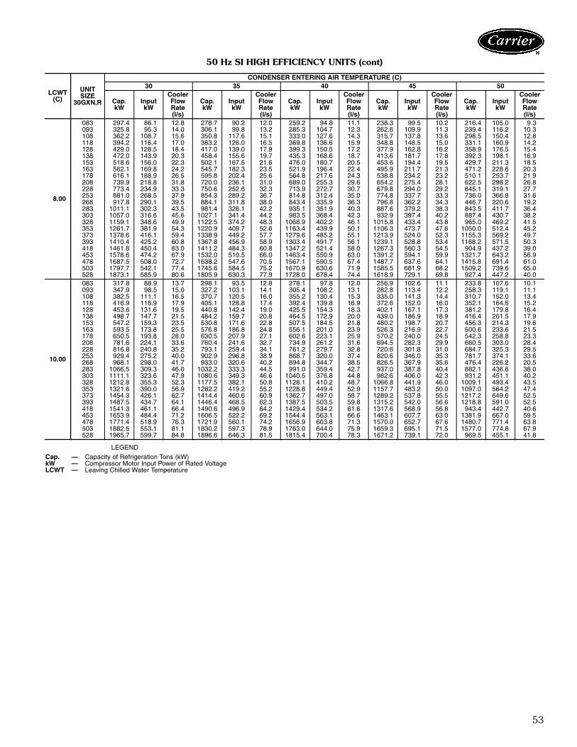
53
50 Hz SI HIGH EFFICIENCY UNITS (cont)
LEGEND
LCWT(C)
UNITSIZE
30GXN,R
CONDENSER ENTERING AIR TEMPERATURE (C)30 35 40 45 50
Cap.kW
InputkW
CoolerFlowRate(l/s)
Cap.kW
InputkW
CoolerFlowRate(l/s)
Cap.kW
InputkW
CoolerFlowRate(l/s)
Cap.kW
InputkW
CoolerFlowRate(l/s)
Cap.kW
InputkW
CoolerFlowRate(l/s)
8.00
083 297.4 86.1 12.8 278.7 90.2 12.0 259.2 94.8 11.1 238.3 99.5 10.2 216.4 105.0 9.3093 325.8 95.3 14.0 306.1 99.8 13.2 285.3 104.7 12.3 262.6 109.9 11.3 239.4 116.2 10.3108 362.2 108.7 15.6 350.8 117.6 15.1 333.0 127.6 14.3 315.7 137.8 13.6 298.5 150.4 12.8118 394.2 116.4 17.0 383.2 126.0 16.5 369.8 136.6 15.9 348.8 148.5 15.0 331.1 160.9 14.2128 429.0 128.5 18.4 417.0 139.0 17.9 399.3 150.5 17.2 377.9 162.8 16.2 358.9 176.5 15.4138 472.0 143.9 20.3 458.4 155.6 19.7 435.3 168.6 18.7 413.6 181.7 17.8 392.3 198.1 16.9153 518.6 156.0 22.3 502.1 167.5 21.6 476.0 180.7 20.5 453.6 194.4 19.5 429.7 211.3 18.5163 562.1 169.8 24.2 545.7 182.3 23.5 521.9 196.4 22.4 495.9 211.7 21.3 471.2 228.6 20.3178 616.1 188.9 26.5 595.8 202.4 25.6 564.8 217.6 24.3 538.8 234.2 23.2 510.1 253.7 21.9208 739.9 218.8 31.8 720.0 236.1 31.0 689.0 255.3 29.6 654.2 275.4 28.1 622.5 298.2 26.8228 773.4 234.9 33.3 750.6 252.6 32.3 713.9 272.7 30.7 679.8 294.0 29.2 645.1 319.1 27.7253 881.0 268.5 37.9 854.3 289.2 36.7 814.8 312.4 35.0 774.8 337.7 33.3 736.0 366.8 31.6268 917.8 290.1 39.5 884.1 311.8 38.0 843.4 335.9 36.3 796.8 362.2 34.3 446.7 220.6 19.2283 1011.1 302.3 43.5 981.4 326.1 42.2 935.1 351.9 40.3 887.6 379.2 38.3 843.5 411.7 36.4303 1057.0 316.6 45.6 1027.1 341.4 44.2 983.5 368.4 42.3 932.9 397.4 40.2 887.4 430.7 38.2328 1159.1 348.6 49.9 1122.5 374.2 48.3 1068.9 402.2 46.1 1015.8 433.4 43.8 965.0 469.2 41.5353 1261.7 381.9 54.3 1220.9 409.7 52.6 1163.4 439.9 50.1 1106.3 473.7 47.6 1050.0 512.4 45.2373 1378.6 416.1 59.4 1338.9 449.2 57.7 1279.6 485.2 55.1 1213.9 524.0 52.3 1155.3 569.2 49.7393 1410.4 425.2 60.8 1367.8 456.9 58.9 1303.4 491.7 56.1 1239.1 528.8 53.4 1168.2 571.5 50.3418 1461.8 450.4 63.0 1411.2 484.3 60.8 1347.2 521.4 58.0 1267.3 560.3 54.5 904.9 437.2 39.0453 1578.6 474.2 67.9 1532.0 510.5 66.0 1463.4 550.9 63.0 1391.2 594.1 59.9 1321.7 643.2 56.9478 1687.5 508.0 72.7 1638.2 547.6 70.5 1567.1 590.5 67.4 1487.7 637.6 64.1 1415.8 691.4 61.0503 1797.7 542.1 77.4 1745.6 584.5 75.2 1670.9 630.6 71.9 1585.5 681.9 68.2 1509.2 739.6 65.0528 1873.1 585.9 80.6 1805.9 630.3 77.9 1728.0 678.4 74.4 1618.9 729.1 69.8 927.4 447.2 40.0
10.00
083 317.8 88.9 13.7 298.1 93.5 12.8 278.1 97.8 12.0 256.9 102.6 11.1 233.8 107.6 10.1093 347.9 98.5 15.0 327.2 103.1 14.1 305.4 108.2 13.1 282.8 113.4 12.2 258.3 119.1 11.1108 382.5 111.1 16.5 370.7 120.5 16.0 355.2 130.4 15.3 335.0 141.3 14.4 310.7 152.0 13.4118 416.9 118.9 17.9 405.1 128.8 17.4 392.4 139.8 16.9 372.6 152.0 16.0 352.1 164.6 15.2128 453.6 131.6 19.5 440.8 142.4 19.0 425.5 154.3 18.3 402.1 167.1 17.3 381.2 179.8 16.4138 498.7 147.7 21.5 484.2 159.7 20.8 464.5 172.9 20.0 439.0 186.9 18.9 416.4 201.5 17.9153 547.2 159.3 23.5 530.8 171.6 22.8 507.5 184.5 21.8 480.2 198.7 20.7 456.3 214.3 19.6163 593.5 173.8 25.5 576.8 186.8 24.8 556.1 201.0 23.9 526.3 216.9 22.7 500.6 233.6 21.5178 650.5 193.8 28.0 630.5 207.9 27.1 602.6 223.1 25.9 570.2 240.0 24.5 542.3 258.8 23.3208 781.6 224.1 33.6 760.4 241.6 32.7 734.9 261.2 31.6 694.5 282.3 29.9 660.5 303.0 28.4228 816.8 240.8 35.2 793.1 259.4 34.1 761.2 279.7 32.8 720.6 301.8 31.0 684.7 325.3 29.5253 929.4 275.2 40.0 902.9 296.8 38.9 868.7 320.0 37.4 820.6 346.0 35.3 781.7 374.1 33.6268 968.1 298.0 41.7 933.0 320.6 40.2 894.8 344.7 38.5 826.5 367.9 35.6 476.4 226.2 20.5283 1066.5 309.3 46.0 1032.2 333.3 44.5 991.0 359.4 42.7 937.0 387.8 40.4 882.1 436.6 38.0303 1111.1 323.6 47.9 1080.6 349.3 46.6 1040.5 376.8 44.8 982.6 406.0 42.3 931.2 451.1 40.2328 1212.8 355.3 52.3 1177.5 382.1 50.8 1128.1 410.2 48.7 1066.8 441.9 46.0 1009.1 493.4 43.5353 1321.6 390.0 56.9 1282.2 419.2 55.2 1228.8 449.4 52.9 1157.7 483.2 50.0 1097.0 564.2 47.4373 1454.3 426.1 62.7 1414.4 460.6 60.9 1362.7 497.0 58.7 1289.2 537.8 55.5 1217.2 649.6 52.5393 1487.5 434.7 64.1 1446.4 468.5 62.3 1387.5 503.5 59.8 1315.2 542.0 56.6 1218.8 591.0 52.5418 1541.3 461.1 66.4 1490.6 496.9 64.2 1429.4 534.2 61.6 1317.6 568.9 56.8 943.4 442.7 40.6453 1653.9 484.4 71.2 1606.5 522.2 69.2 1544.4 563.1 66.6 1463.1 607.7 63.0 1381.9 667.0 59.5478 1771.4 518.9 76.3 1721.9 560.1 74.2 1656.9 603.8 71.3 1570.0 652.7 67.6 1480.7 771.4 63.8503 1882.5 553.1 81.1 1830.2 597.3 78.9 1763.0 644.0 75.9 1659.3 695.1 71.5 1577.0 774.8 67.9528 1965.7 599.7 84.8 1896.6 646.3 81.5 1815.4 700.4 78.3 1671.2 739.1 72.0 969.5 455.1 41.8
Cap. — Capacity of Refrigeration Tons (kW)kW — Compressor Motor Input Power of Rated VoltageLCWT — Leaving Chilled Water Temperature

54
UNIT OPERATING RANGE*
*Maximum ambient temperature and percent of unit capacity will vary based on unit loadand return water temperature. All models are qualified for use at 125 F (46 C). Somemodels may require the high ambient fan option. Contact your local Carrier representativeto obtain performance data using the Carrier electronic catalog.
†For applications requiring cooler leaving water temperature operation at less than 40 F(4.4 C), the units require the use of antifreeze and application may require one of the spe-cial order brine options. Contact your local Carrier representative for more information.
**For applications requiring cooler entering water temperature operation at less than 45 F(7.2 C), contact your local Carrier representative for unit selection using the Carrier elec-tronic catalog.
††Requires optional or accessory low ambient kit for operation below 15 F (–9 C). All othermodels require the low ambient control for operation below 0° F (– 17.8 C).
NOTES:1. The 30GXN,R units will start with loop temperatures up to 95 F (35 C).2. Nominal flow rates required at ARI conditions 44 F (7 C) leaving fluid temperature, 54 F
(12 C) entering water temperature, 95 F (35 C) ambient. Fouling factor 0.00010 ft2-hr-F/Btu (0.000018 m2-K/kW).
3. To obtain proper temperature control, cooler loop fluid volume must be at least 3 gal/ton(3.23 L/kW) of chiller nominal capacity for air conditioning and at least 6 gal/ton (6.5 L/kW)for process applications or systems that must operate in low ambient temperatures (below32 F [0° C]).
4. Where winds of 5 mph (2.2 m/s) or greater are anticipated at outdoor ambient tempera-tures below 32 F (0° C), wind baffles are required.
ITEM MAX MIN NOMINALCooler Leaving Fluid Temperature† 60 F (15 C) 40 F (4.4 C) —Cooler Entering Fluid Temperature** 70 F (21.1 C) 45 F (7.2 C) —
Cooler Flow Rates 30GXN,R Cooler Number ofPasses
Max Cooler Temp Difference Reference Min Flow Rate† Nominal Flow RateF C Gpm L/s Gpm L/s
080, 083minus 1 pass 2 13 7.4 136 8.6
182 11.5std 3 20 11.1 91 5.7plus 1 pass 4 27 14.8 68 4.3
090, 093minus 1 pass 2 13 7.4 149 9.4
199 12.6std 3 20 11.1 100 6.3plus 1 pass 4 27 14.8 75 4.7
106, 108minus 1 pass 2 13 7.4 176 11.1
234 14.8std 3 20 11.1 117 7.4plus 1 pass 4 27 14.8 88 5.5
115minus 1 pass 2 13 7.4 191 12.0
254 16.1std 3 20 11.1 127 8.0plus 1 pass 4 27 14.8 95 6.0
118minus 1 pass 1 10 5.6 254 16.1
254 16.1std 2 20 11.1 127 8.0plus 1 pass 3 30 16.7 85 5.4
125minus 1 pass 2 13 7.4 209 13.2
278 17.6std 3 20 11.1 139 8.8plus 1 pass 4 27 14.8 104 6.6
128minus 1 pass 1 10 5.6 278 17.6
278 17.6std 2 20 11.1 139 8.8plus 1 pass 3 30 16.7 93 5.9
135minus 1 pass 2 13 7.4 229 14.4
305 19.2std 3 20 11.1 152 9.6plus 1 pass 4 27 14.8 114 7.2
138minus 1 pass 1 10 5.6 305 19.2
305 19.2std 2 20 11.1 152 9.6plus 1 pass 3 30 16.7 102 6.4
150, 153minus 1 pass 1 10 5.6 336 21.2
336 21.2std 2 20 11.1 168 10.6plus 1 pass 3 30 16.7 112 7.1
160, 163minus 1 pass 1 10 5.6 364 23.0
364 23.0std 2 20 11.1 182 11.5plus 1 pass 3 30 16.7 121 7.7
175, 178††minus 1 pass 1 10 5.6 401 25.3
401 25.3std 2 20 11.1 200 12.6plus 1 pass 3 30 16.7 134 8.4
205, 208††minus 1 pass 1 10 5.6 461 29.1
461 29.1std 2 20 11.1 230 14.5plus 1 pass 3 30 16.7 154 9.7
225, 228††minus 1 pass 1 10 5.6 502 31.6
502 31.6std 2 20 11.1 251 15.8plus 1 pass 3 30 16.7 167 10.5
250, 253††minus 1 pass 1 10 5.6 562 35.4
562 35.4std 2 20 11.1 281 17.7plus 1 pass 3 30 16.7 187 11.8
264, 268††minus 1 pass 1 10 5.6 588 37.1
588 37.1std 2 20 11.1 294 18.6plus 1 pass 3 30 16.7 196 12.4
281††minus 1 pass 1 10 5.6 641 40.5
641 40.5std 2 20 11.1 321 20.2plus 1 pass 3 30 16.7 214 13.5
301††minus 1 pass 1 10 5.6 689 43.4
689 43.4std 2 20 11.1 344 21.7plus 1 pass 3 30 16.7 230 14.5
325††minus 1 pass 1 10 5.6 741 46.8
741 46.8std 2 20 11.1 371 23.4plus 1 pass 3 30 16.7 247 15.6
350††minus 1 pass 1 10 5.6 801 50.5
801 50.5std 2 20 11.1 401 25.3plus 1 pass 3 30 16.7 267 16.8
Performance data (cont)
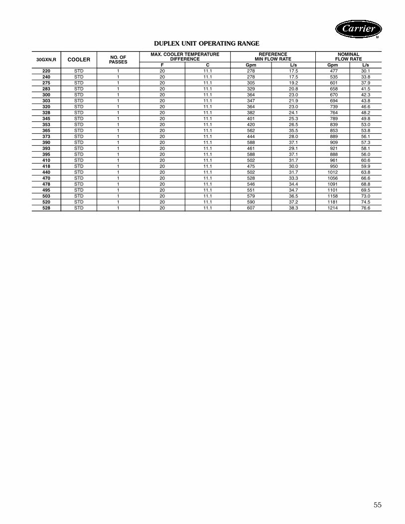
55
DUPLEX UNIT OPERATING RANGE
30GXN,R COOLER NO. OFPASSES
MAX. COOLER TEMPERATUREDIFFERENCE
REFERENCEMIN FLOW RATE
NOMINALFLOW RATE
F C Gpm L/s Gpm L/s220 STD 1 20 11.1 278 17.5 477 30.1240 STD 1 20 11.1 278 17.5 535 33.8275 STD 1 20 11.1 305 19.2 601 37.9283 STD 1 20 11.1 329 20.8 658 41.5300 STD 1 20 11.1 364 23.0 670 42.3303 STD 1 20 11.1 347 21.9 694 43.8320 STD 1 20 11.1 364 23.0 739 46.6328 STD 1 20 11.1 382 24.1 764 48.2345 STD 1 20 11.1 401 25.3 789 49.8353 STD 1 20 11.1 420 26.5 839 53.0365 STD 1 20 11.1 562 35.5 853 53.8373 STD 1 20 11.1 444 28.0 889 56.1390 STD 1 20 11.1 588 37.1 909 57.3393 STD 1 20 11.1 461 29.1 921 58.1395 STD 1 20 11.1 588 37.1 888 56.0410 STD 1 20 11.1 502 31.7 961 60.6418 STD 1 20 11.1 475 30.0 950 59.9440 STD 1 20 11.1 502 31.7 1012 63.8470 STD 1 20 11.1 528 33.3 1056 66.6478 STD 1 20 11.1 546 34.4 1091 68.8495 STD 1 20 11.1 551 34.7 1101 69.5503 STD 1 20 11.1 579 36.5 1158 73.0520 STD 1 20 11.1 590 37.2 1181 74.5528 STD 1 20 11.1 607 38.3 1214 76.6

56
Performance data (cont)
080,
083,
090,
093
106,
108,
115
118,
125,
135
128,
138,
150,
153
160,
163,
175
178
50
40
30
20
1098
7
6
5
4
3
2
1100 200 300 400 500 600 700
COOLER FLOW RATE (GPM)
PR
ES
SU
RE
DR
OP
(ftw
g)
080,
083,
090,
093
106,
108,
115
118,
125,
135
128,
138,
150,
153
160,
163,
175
178
200
100
90
80
70
60
50
40
30
20
10
10 20 30 40
COOLER FLOW RATE (L/s)
PR
ES
SU
RE
DR
OP
(kP
a)
1000
100
10
110 100
COOLER FLOW RATE (L/s)
PR
ES
SU
RE
DR
OP
(kpa
)
205, 208
225, 228
250, 253, 264, 268
100
10
1100 1000
COOLER FLOW RATE (GPM)
PR
ES
SU
RE
DR
OP
(ftw
g)
205,
208
225
228
250,
253,
264,
268
NOTE: Ft of water = 2.31 x psig.
30GXN,R080-178 COOLER PRESSURE DROP —ENGLISH30GXN,R080-178 COOLER PRESSURE DROP —
SI
30GXN,R205-268 COOLER PRESSURE DROP —ENGLISH
30GXN,R205-268 COOLER PRESSURE DROP —SI

57
1000
100
10
110
COOLER FLOW RATE (L/s)100
PR
ES
SU
RE
DR
OP
(kpa
)
100
10
1100
COOLER FLOW RATE (GPM)10000
PR
ES
SU
RE
DR
OP
(ftw
g)
30GXN,R281-350 COOLER PRESSURE DROP —SI
NOTE: Ft of water = 2.31 x psig.
30GXN,R281-350 COOLER PRESSURE DROP —ENGLISH
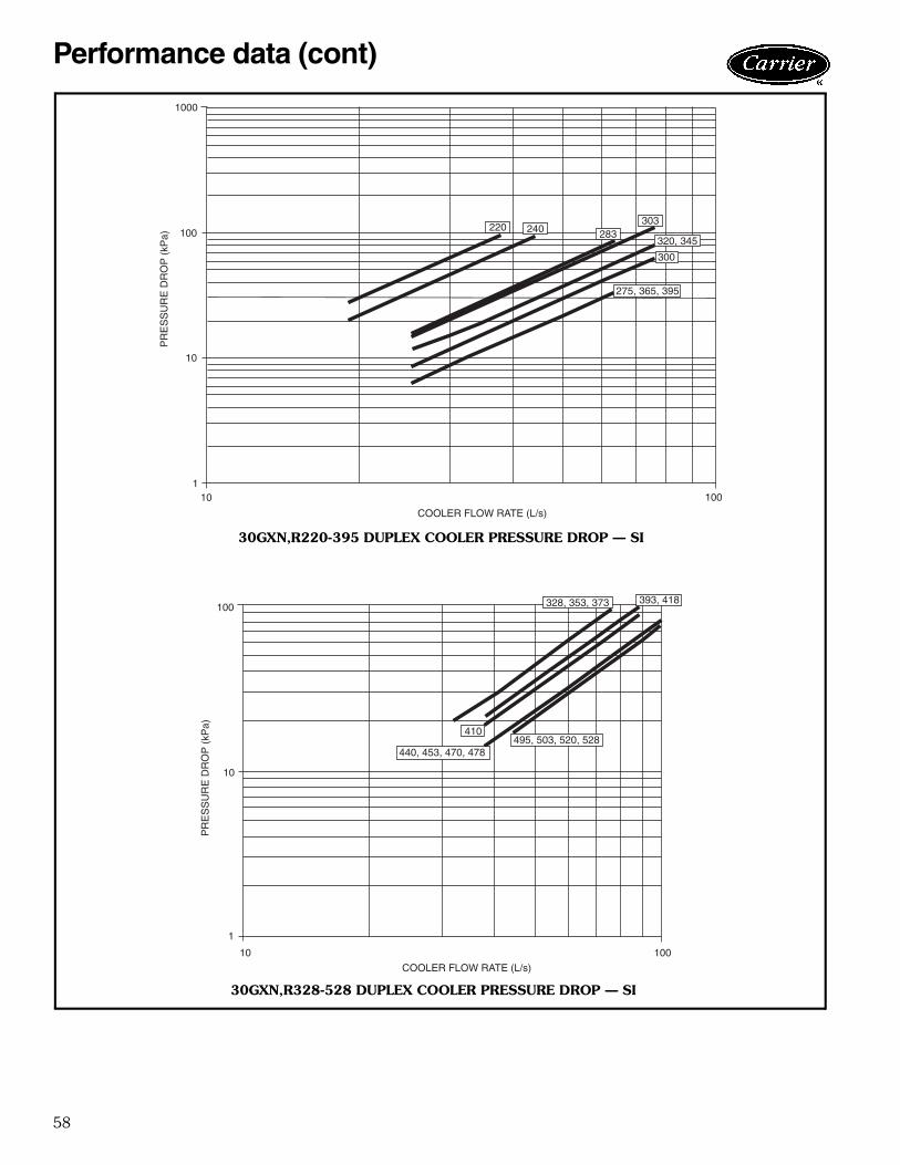
58
Performance data (cont)
100
COOLER FLOW RATE (L/s)
10
1000
100
10
PR
ES
SU
RE
DR
OP
(kP
a)
1
220 240 283303
300
320, 345
275, 365, 395
100
COOLER FLOW RATE (L/s)
10
100
10
PR
ES
SU
RE
DR
OP
(kP
a)
1
410
328, 353, 373 393, 418
495, 503, 520, 528440, 453, 470, 478
30GXN,R220-395 DUPLEX COOLER PRESSURE DROP — SI
30GXN,R328-528 DUPLEX COOLER PRESSURE DROP — SI

59
100001000
COOLER FLOW RATE (GPM)
100
1
10
100
PR
ES
SU
RE
DR
OP
(ftw
g)
240283
303
300
320, 345
275, 365, 395
220
100
10
1
100 1000 10000
COOLER FLOW RATE (GPM)
PR
ES
SU
RE
DR
OP
(ftw
g)
328, 353, 373
410
393, 418
495, 503, 520, 528
440, 453, 470, 478
30GXN,R220-395 DUPLEX COOLER PRESSURE DROP — ENGLISH
30GXN,R328-528 DUPLEX COOLER PRESSURE DROP — ENGLISH

60
Typical piping and wiring
NOTES:1. Chiller must be installed level (1/8 in. per linear foot, [1 cm per linear meter]) to maintain
proper compressor oil return.2. Wiring and piping shown are general points-of-connection guides only and are not intended
for a specific installation. Wiring and piping shown are for a quick overview of system andare not in accordance with recognized standards.
3. All wiring must comply with applicable local and national codes.4. All piping must follow standard piping techniques.
LEGENDAUX — AuxiliaryCKT — CircuitFD — Field-Supplied DisconnectST — Starter
Airflow Through Condenser
Airflow Through Air-HandlingUnitPower WiringChilled Water Piping

61
Typical piping and wiring — duplex units
NOTES:1. Chiller must be installed level (1/8 in. per linear foot [1 cm per linear meter]) to maintain
proper compressor oil return and hydraulics.2. Wiring and piping shown are general points-of-connection guides only and are not intended
for a specific installation. Wiring and piping shown are for a quick overview of system andare not in accordance with recognized standards.
3. All wiring must comply with applicable local and national codes.4. All piping must follow standard piping techniques.
LEGENDAUX — AuxiliaryCKT — CircuitFD — Field-Supplied DisconnectST — Starter
Airflow Through Condenser
Airflow Through Air-HandlingUnitPower WiringChilled Water Piping

62
ELECTRICAL DATA REDUCED AMBIENT 115 F DATA
LEGEND
*Wye-delta start is standard. Across-the-line start is not available.†Circuit A/Circuit B.
NOTES:1. Main power must be supplied from a field-supplied fused electrical service with
a (factory or field-installed) disconnect located in sight from the unit.2. On 230-3-50 units, cooler heaters, oil heaters and control circuiting power must
be supplied from a separate source via a field-supplied disconnect. On 380/415-3-50 units, control voltage is tapped from line to neutral. No additional sup-ply is required. If a separate power source is required, disconnect the wiresbetween the control and power terminal blocks.
3. Maximum incoming wire size for each terminal block is 500 kcmil.4. Maximum allowable supply voltage phase imbalance is voltage 2%.5. Never operate a motor where a phase imbalance in supply voltage is greater
than 2%.
UNIT30GXN,R
UNIT VOLTAGEPOWERSUPPLY
QTY. REQD
STANDARD CONDENSER FAN CONTROL CIRCUIT
V-Hz(3 Ph)
Supplied # PowerSupply
ConductorsMCA MOCP
ICF Rec Fuse Size V-Hz(Single Ph)
MCA andMOCPMin Max XL WD XL WD
080 230-50 207 253 1 3 340.6 450 * 510.9 * 400 230-50 15380/415-50 342 440 1 3 205.6 250 805.1 316.1 250 250 230-50 15
083 230-50 207 253 1 3 319.4 450 * 506.6 * 400 230-50 15380/415-50 342 440 1 3 192.8 250 802.9 313.9 225 225 230-50 15
090 230-50 207 253 1 6 385.5 500 * 581.9 * 450 230-50 15380/415-50 342 440 1 3 232.8 300 946.1 360.1 300 300 230-50 15
093 230-50 207 253 1 6 352.0 500 * 577.6 * 400 230-50 15380/415-50 342 440 1 3 212.4 300 943.9 357.9 250 250 230-50 15
106 230-50 207 253 1 6 455.5 600 * 645.6 * 600 230-50 15380/415-50 342 440 1 3 274.6 400 1056.6 399.6 350 350 230-50 15
108 230-50 207 253 1 6 418.9 600 * 650.5 * 500 230-50 15380/415-50 342 440 1 3 252.8 350 1059.9 402.9 300 300 230-50 15
115 230-50 207 253 1 6 493.7 700 * 793.7 * 600 230-50 15380/415-50 342 440 1 3 297.9 450 1331.5 492.5 350 350 230-50 15
118 230-50 207 253 1 6 457.1 600 * 688.7 * 600 230-50 15380/415-50 342 440 1 3 275.9 350 1083.0 426.0 350 350 230-50 15
125 230-50 207 253 1 6 525.7 700 * 825.7 * 600 230-50 15380/415-50 342 440 1 3 317.2 450 1350.8 511.8 400 400 230-50 15
128 230-50 207 253 1 6 487.7 700 * 822.7 * 600 230-50 15380/415-50 342 440 1 3 294.4 400 1349.0 510.0 350 350 230-50 15
138 230-50 207 253 1 6 529.8 700 * 864.8 * 600 230-50 15380/415-50 342 440 1 3 319.8 450 1374.4 535.4 400 400 230-50 15
153 230-50 207 253 1 6 609.7 800 * 894.6 * 700 230-50 15380/415-50 342 440 1 3 368.0 500 1420.0 555.0 450 450 230-50 15
163 230-50 207 253 2 9 417.7/284† 700/500† * 702.7/619.0† * 500/350† 230-50 15380/415-50 342 440 1 6 389.3 500 1441.3 576.3 450 450 230-50 15
178 230-50 207 253 2 9 417.7/353† 800/600† * 985.1/638.0 * 800/450† 230-50 15380/415-50 342 440 1 6 422.6 500 1474.6 609.6 500 500 230-50 15
208 230-50 207 253 2 9 511/358† 700/500† * 846.2/590.0† * 600/450† 230-50 15380/415-50 342 440 1 6 477 600 1531.1 692.1 600 600 230-50 15
228 230-50 207 253 2 9 580/358† 800/500† * 901.4/590.0† * 700/450† 230-50 15380/415-50 342 440 1 6 518 600 1570.1 725.4 600 600 230-50 15
253 230-50 207 253 2 12 635/404† 800/600† * 920.4/739.0† * 800/500† 230-50 15380/415-50 342 440 1 6 573 700 1624.8 780.0 700 700 230-50 15
268 230-50 207 253 2 12 635/473† 800/700† * 920.4/758.0† * 800/600† 230-50 15380/415-50 342 440 1 6 606 700 1658.0 793.0 700 700 230-50 15
ICF — Maximum Instantaneous Current FlowMCA — Minimum Circuit Ampacity (for wire sizing)MOCP — Maximum Overcurrent ProtectionRec Fuse Size — Recommended Dual-Element Fuse Amps (150% of largest
compressor rated load amps [RLA] plus 100% of remainingcompressor RLAs and sum of condenser fan full load amps[FLAs]. Choose next largest standard fuse size.)
WD — Wye-Delta StartXL — Across-the-Line Start
IMPORTANT: Contact your local electric utility company immediately ifthe supply voltage phase imbalance is more than 2%.
Electrical data
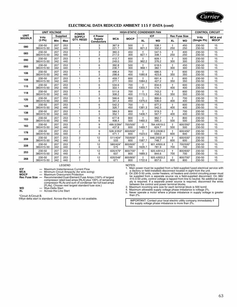
63
ELECTRICAL DATA REDUCED AMBIENT 115 F DATA (cont)
LEGEND
*Circuit A/Circuit B.†Wye-delta start is standard. Across-the-line start is not available.
NOTES:1. Main power must be supplied from a field-supplied fused electrical service with
a (factory or field-installed) disconnect located in sight from the unit.2. On 230-3-50 units, cooler heaters, oil heaters and control circuiting power must
be supplied from a separate source via a field-supplied disconnect. On 380/415-3-50 units, control voltage is tapped from line to neutral. No additional sup-ply is required. If a separate power source is required, disconnect the wiresbetween the control and power terminal blocks.
3. Maximum incoming wire size for each terminal block is 500 kcmil.4. Maximum allowable supply voltage phase imbalance is voltage 2%.5. Never operate a motor where a phase imbalance in supply voltage is greater
than 2%.
UNIT30GXN,R
UNIT VOLTAGEPOWERSUPPLY
QTY. REQD
HIGH-STATIC CONDENSER FAN CONTROL CIRCUIT
V-Hz(3 Ph)
Supplied # PowerSupply
ConductorsMCA MOCP
ICF Rec Fuse Size V-Hz(Single Ph)
MCA andMOCPMin Max XL WD XL WD
080 230-50 207 253 1 3 367.9 500 † 538.1 † 450 230-50 15380/415-50 342 440 1 3 221.7 300 821.2 332.2 250 250 230-50 15
083 230-50 207 253 1 3 360.3 450 † 547.5 † 400 230-50 15380/415-50 342 440 1 3 217.0 300 827.1 338.1 250 250 230-50 15
090 230-50 207 253 1 6 412.7 600 † 609.1 † 500 230-50 15380/415-50 342 440 1 3 249.0 350 962.2 376.2 300 300 230-50 15
093 230-50 207 253 1 6 392.8 500 † 618.5 † 450 230-50 15380/415-50 342 440 1 3 236.7 300 968.1 382.1 300 300 230-50 15
106 230-50 207 253 1 6 496.4 700 † 686.5 † 600 230-50 15380/415-50 342 440 1 3 298.8 400 1080.8 423.8 350 350 230-50 15
108 230-50 207 253 1 6 459.7 600 † 691.4 † 600 230-50 15380/415-50 342 440 1 3 277.1 350 1084.2 427.2 350 350 230-50 15
115 230-50 207 253 1 6 534.6 700 † 834.6 † 600 230-50 15380/415-50 342 440 1 3 322.1 450 1355.7 516.7 400 400 230-50 15
118 230-50 207 253 1 6 511.6 700 † 743.2 † 600 230-50 15380/415-50 342 440 1 3 308.2 400 1115.3 458.3 350 350 230-50 15
125 230-50 207 253 1 6 566.6 800 † 866.6 † 700 230-50 15380/415-50 342 440 1 3 341.4 450 1375.0 536.0 400 400 230-50 15
128 230-50 207 253 1 6 542.2 700 † 877.2 † 600 230-50 15380/415-50 342 440 1 3 326.7 450 1381.3 542.3 400 400 230-50 15
138 230-50 207 253 1 6 584.3 800 † 919.3 † 700 230-50 15380/415-50 342 440 1 3 352.1 450 1406.7 567.7 400 400 230-50 15
153 230-50 207 253 1 6 677.8 800 † 962.7 † 800 230-50 15380/415-50 342 440 1 6 408.4 500 1460.3 595.3 500 500 230-50 15
163 230-50 207 253 2 9 499.5/284* 700/500* † 784.4/619.0 † 600/350* 230-50 15380/415-50 342 440 1 6 437.8 600 1489.7 624.7 500 500 230-50 15
178 230-50 207 253 2 9 528.3/353* 800/600* † 813.2/638.0 † 600/450* 230-50 15380/415-50 342 440 1 6 471.1 600 1523.0 658.0 600 600 230-50 15
208 230-50 207 253 2 12 511/424* 700/600* † 846.2/655.8* † 600/500* 230-50 15380/415-50 342 440 1 6 533 600 1587.7 748.7 600 600 230-50 15
228 230-50 207 253 2 12 580/424* 800/600* † 901.4/655.8 † 700/500* 230-50 15380/415-50 342 440 1 6 575 700 1626.7 781.9 700 700 230-50 15
253 230-50 207 253 2 12 635/479* 800/700* † 920.4/814.2 † 800/600* 230-50 15380/415-50 342 440 1 6 637 800 1689.3 844.6 700 700 230-50 15
268 230-50 207 253 2 12 635/548* 800/800* † 920.4/833.2 † 800/700* 230-50 15380/415-50 342 440 1 6 671 800 1722.6 857.6 800 800 230-50 15
ICF — Maximum Instantaneous Current FlowMCA — Minimum Circuit Ampacity (for wire sizing)MOCP — Maximum Overcurrent ProtectionRec Fuse Size — Recommended Dual-Element Fuse Amps (150% of largest
compressor rated load amps [RLA] plus 100% of remainingcompressor RLAs and sum of condenser fan full load amps[FLAs]. Choose next largest standard fuse size.)
WD — Wye-Delta StartXL — Across-the-Line Start
IMPORTANT: Contact your local electric utility company immediately ifthe supply voltage phase imbalance is more than 2%.

64
ELECTRICAL DATA HIGH AMBIENT 125 F DATA, STANDARD CONDENSER FAN
LEGEND
*Circuit A/Circuit B.†Wye-delta start is standard. Across-the-line start is not available.**Amperages in ( ) are for units with cooler heaters installed.
NOTES:1. Main power must be supplied from a field-supplied fused electrical service with a (fac-
tory or field-installed) disconnect located in sight from the unit.2. On 230-3-50 units, cooler heaters, oil heaters and control circuiting power must be
supplied from a separate source via a field-supplied disconnect. On 380/415-3-50units, control voltage is tapped from line to neutral. No additional supply is required. Ifa separate power source is required, disconnect the wires between the control andpower terminal blocks.
3. Maximum incoming wire size for each terminal block is 500 kcmil.4. Maximum allowable supply voltage phase imbalance is voltage 2%.5. Never operate a motor where a phase imbalance in supply voltage is greater than
2%.
UNIT30GXN,R
UNIT VOLTAGE POWERSUPPLY
QTY. REQ’D
STANDARD CONDENSER FAN CONTROL CIRCUIT
V-Hz(3 Ph)
Supplied # Power SupplyConductors MCA MOCP
ICF Rec Fuse Size V-Hz(Single Ph)
MCA andMOCP**Min Max XL WD XL WD
080 230-50 207 253 1 3 352.4 500 † 514.7 † 400 230-50 15380/415-50 342 440 1 3 212.8 300 807.6 318.6 250 250 230-50 15
083 230-50 207 253 1 3 328.3 450 † 510.1 † 400 230-50 15380/415-50 342 440 1 3 198.2 250 805.0 316.0 225 225 230-50 15
090 230-50 207 253 1 6 400.5 500 † 585.7 † 450 230-50 15380/415-50 342 440 1 3 241.7 350 948.6 362.6 300 300 230-50 15
093 230-50 207 253 1 3 364.1 500 † 581.1 † 450 230-50 15380/415-50 342 440 1 3 219.8 300 946.0 360.0 250 250 230-50 15
106 230-50 207 253 1 6 462.6 700 † 649.4 † 600 230-50 15380/415-50 342 440 1 3 278.6 400 1059.1 402.1 350 350 230-50 15
108 230-50 207 253 1 6 438.4 600 † 663.6 † 500 230-50 15380/415-50 342 440 1 3 264.6 350 1067.8 410.8 300 300 230-50 15
115 230-50 207 253 1 6 497.5 700 † 797.5 † 600 230-50 15380/415-50 342 440 1 3 300.5 450 1334.1 495.1 350 350 230-50 15
118 230-50 207 253 1 6 481.0 600 † 706.2 † 600 230-50 15380/415-50 342 440 1 3 290.3 400 1093.6 436.6 350 350 230-50 15
125 230-50 207 253 1 6 528.3 700 † 828.3 † 600 230-50 15380/415-50 342 440 1 3 318.5 450 1352.1 513.1 400 400 230-50 15
128 230-50 207 253 1 6 540.3 700 † 840.2 † 700 230-50 15380/415-50 342 440 1 3 326.1 450 1359.6 520.6 400 400 230-50 15
135 230-50 207 253 1 6 559.0 800 † 859.0 † 700 230-50 15380/415-50 342 440 1 3 341.5 450 1375.1 536.1 400 400 230-50 15
138 230-50 207 253 1 6 570.0 800 † 869.9 † 700 230-50 15380/415-50 342 440 1 3 344.0 450 1377.5 538.5 400 400 230-50 15
150 230-50 207 253 1 6 605.4 800 † 900.6 † 700 230-50 15380/415-50 342 440 1 3 366.8 500 1395.7 556.7 450 450 230-50 15
153 230-50 207 253 1 6 653.0 800 † 899.7 † 800 230-50 15380/415-50 342 440 1 3 394.2 500 1423.0 558.0 450 450 230-50 15
160 230-50 207 253 1 6 689.5 1000 † 936.3 † 800 230-50 15380/415-50 342 440 1 6 415.7 600 1445.0 580.0 500 500 230-50 15
163 230-50 207 253 2 9 456.0/319* 700/500* † 702.7/619.0* † 600/400* 230-50 15380/415-50 342 440 1 6 429.3 600 1458.2 593.2 500 500 230-50 15
175 230-50 207 253 2 12 445.0/391.1* 700/700* † 691.9/638.0* † 600/500* 230-50 15380/415-50 342 440 1 6 456.8 600 1486.2 621.2 600 600 230-50 15
178 230-50 207 253 2 12 456.0/319* 1000/700 † 1015.8/638.0* † 1000/500* 230-50 15380/415-50 342 440 1 6 464.2 600 1493.1 628.1 600 600 230-50 15
205 230-50 207 253 2 12 465/466* 700/700* † 765.2/713.0* † 600/600* 230-50 15 (25)380-415-50 342 440 1 6 511 600 1540.1 696.7 600 600 230-50 15 (25)
208 230-50 207 253 2 12 574/365* 800/500* † 874.3/590.0* † 700/450* 230-50 15380/415-50 342 440 1 6 518 600 1551.1 712.1 600 600 230-50 15
225 230-50 207 253 2 12 568/466* 800/700* † 815.0/713.0* † 700/600* 230-50 15 (25)380/415-50 342 440 1 6 563 700 1592.7 727.7 700 700 230-50 15 (25)
228 230-50 207 253 2 12 647/365* 800/500* † 932.0/590.0* † 800/450* 230-50 15380/415-50 342 440 1 6 561 700 1590.1 746.9 700 700 230-50 15
250 230-50 207 253 2 12 646/481* 800/700* † 931.9/728.0* † 800/600* 230-50 15 (25)380/415-50 342 440 1 6 617 800 1646.6 803.2 700 700 230-50 15 (25)
253 230-50 207 253 2 12 704/439* 1000/600* † 951.0/739.0* † 800/600* 230-50 15380/415-50 342 440 1 6 631 800 1660.1 817.0 700 700 230-50 15
264 230-50 207 253 2 12 704/481* 1000/700* † 950.9/728.0* † 800/600* 230-50 15 (25)380/415-50 342 440 1 6 652 800 1681.2 816.2 700 700 230-50 15 (25)
268 230-50 207 253 2 12 704/511 1000/800 † 951.0/758.0 † 800/600* 230-50 15380/415-50 342 440 1 6 666 800 1695.0 830.0 800 800 230-50 15
281 380/415-50 342 440 1 6 689 800 1718.8 853.6 800 800 230-50 15 (25)
301 380/415-50 342 440 2 9 365/417* 500/600* 1394.5/1446.7* 529.5/581.7* 450/500* 450/500* 230-50 15 (25)
325 380/415-50 342 440 2 12 390/442* 500/600* 1418.9/1471.1* 553.9/606.1* 450/500* 450/500* 230-50 15 (25)
350 380/415-50 342 440 2 12 424/476* 600/600* 1453.5/1505.7* 588.5/640.7* 500/600* 500/600* 230-50 15 (25)
ICF — Maximum Instantaneous Current FlowMCA — Minimum Circuit Ampacity (for wire sizing)MOCP — Maximum Overcurrent ProtectionRec Fuse Size — Recommended Dual-Element Fuse Amps (150% of largest
compressor rated load amps [RLA] plus 100% of remainingcompressor RLAs and sum of condenser fan full load amps[FLAs]. Choose next largest standard fuse size.)
WD — Wye-Delta StartXL — Across-the-Line Start
IMPORTANT: Contact your local electric utility company immediately ifthe supply voltage phase imbalance is more than 2%.
Electrical data (cont)

65
ELECTRICAL DATA HIGH AMBIENT 125 F DATA, DUPLEX UNITS (Standard Condenser Fan)
LEGEND
*Circuit A/Circuit B.†Wye-delta start is standard. Across-the-line start is not available.**Amperages in ( ) are for units with cooler heaters installed.
NOTES:1. Main power must be supplied from a field-supplied fused electrical service with a
(factory or field-installed) disconnect located in sight from the unit.2. On 230-3-50 units, cooler heaters, oil heaters and control circuiting power must be
supplied from a separate source via a field-supplied disconnect. On 380/415-3-50units, control voltage is tapped from line to neutral. No additional supply is required. Ifa separate power source is required, disconnect the wires between the control andpower terminal blocks.
3. Maximum incoming wire size for each terminal block is 500 kcmil.4. Maximum allowable supply voltage phase imbalance is voltage 2%.5. Never operate a motor where a phase imbalance in supply voltage is greater than
2%.
UNIT30GXN,R
UNIT VOLTAGE POWERSUPPLY
QTY. REQ’D
STANDARD CONDENSER FAN CONTROL CIRCUITV-Hz
(3 Ph)Supplied # Power Supply
Conductors MCA MOCPICF Rec Fuse Size V-Hz
(Single Ph)MCA andMOCP**Min Max XL WD XL WD
220B 230-50 207 253 1 6 400.5 500 † 585.7 † 450 230-50 15380/415-50 342 440 1 3 241.7 350 948.6 362.6 300 300 230-50 15
240B 230-50 207 253 1 6 497.5 700 † 797.5 † 600 230-50 15380/415-50 342 440 1 3 300.5 450 1334.1 495.1 350 350 230-50 15
220A, 240A 230-50 207 253 1 6 528.3 700 † 828.3 † 600 230-50 15380/415-50 342 440 1 3 318.5 450 1352.1 513.1 400 400 230-50 15
275A/B, 300B,365B, 395B
230-50 207 253 1 6 559.0 800 † 859.0 † 700 230-50 15380/415-50 342 440 1 3 341.5 450 1375.1 536.1 400 400 230-50 15
283B, 303B,373B
230-50 207 253 1 6 570.0 800 † 869.9 † 700 230-50 15380/415-50 342 440 1 3 344.0 450 1377.5 538.5 400 400 230-50 15
283A, 328B,393B, 418B
230-50 207 253 1 6 653.0 800 † 899.7 † 800 230-50 15380/415-50 342 440 1 3 394.2 500 1423.0 558.0 450 450 230-50 15
303A 230-50 207 253 2 9 456.0/319* 700/500* † 702.7/619.0* † 600/400* 230-50 15380/415-50 342 440 1 6 429.3 600 1458.2 593.2 500 500 230-50 15
328A,353A/B
230-50 207 253 2 12 456.0/391* 1000/700* † 1015.8/638.0* † 1000/500* 230-50 15380/415-50 342 440 1 6 464.2 600 1493.1 628.1 600 600 230-50 15
300A,320A/B
230-50 207 253 1 6 689.5 1000 † 936.3 † 800 230-50 15380/415-50 342 440 1 6 415.7 600 1445.0 580.0 500 500 230-50 15
345A/B 230-50 207 253 2 12 445.0/391.1* 700/700* † 691.9/638.0* † 600/500* 230-50 15380/415-50 342 440 1 6 456.8 600 1486.2 621.2 600 600 230-50 15
410B 230-50 207 253 2 12 465/466* 700/700* † 765.2/713.0* † 600/600* 230-50 15 (25)380-415-50 342 440 1 6 511 600 1540.1 696.7 600 600 230-50 15 (25)
410A,440A/B, 470B
230-50 207 253 2 12 568/466* 800/700* † 815.0/713.0* † 700/600* 230-50 15 (25)380/415-50 342 440 1 6 563 700 1592.7 727.7 700 700 230-50 15 (25)
365A, 470A,495A/B
230-50 207 253 2 12 646/481* 800/700* † 931.9/728.0* † 800/600* 230-50 15 (25)380/415-50 342 440 1 6 617 800 1646.6 803.2 700 700 230-50 15 (25)
395A,520A/B
230-50 207 253 2 12 704/481* 1000/700* † 950.9/728.0* † 800/600* 230-50 15 (25)380/415-50 342 440 1 6 652 800 1681.2 816.2 700 700 230-50 15 (25)
453A/B,478B
230-50 207 253 2 12 647/365* 800/500* 932.0/590.0* 800/450* 230-50 15 (25)380/415-50 342 440 1 6 561 700 1590.1 746.9 700 700 230-50 15 (25)
373A, 393A478A, 503A/B
230-50 207 253 2 12 704/439* 1000/600* † 951.0/739.0* † 800/600* 230-50 15 (25)380/415-50 342 440 1 6 631 800 1660.1 817.0 700 700 230-50 15 (25)
418A, 528A/B 230-50 207 253 2 12 704/511* 1000/800* † 951.0/758.0* † 800/600* 230-50 15 (25)380/415-50 342 440 1 6 666 800 1695.0 830.0 800 800 230-50 15 (25)
ICF — Maximum Instantaneous Current FlowMCA — Minimum Circuit Ampacity (for wire sizing)MOCP — Maximum Overcurrent ProtectionRec Fuse Size — Recommended Dual-Element Fuse Amps (150% of
largest compressor rated load amps [RLA] plus 100%of remaining compressor RLAs and sum of condenserfan full load amps [FLAs]. Choose next largest standardfuse size.)
WD — Wye-Delta StartXL — Across-the-Line Start
IMPORTANT: Contact your local electric utility company immediately ifthe supply voltage phase imbalance is more than 2%.
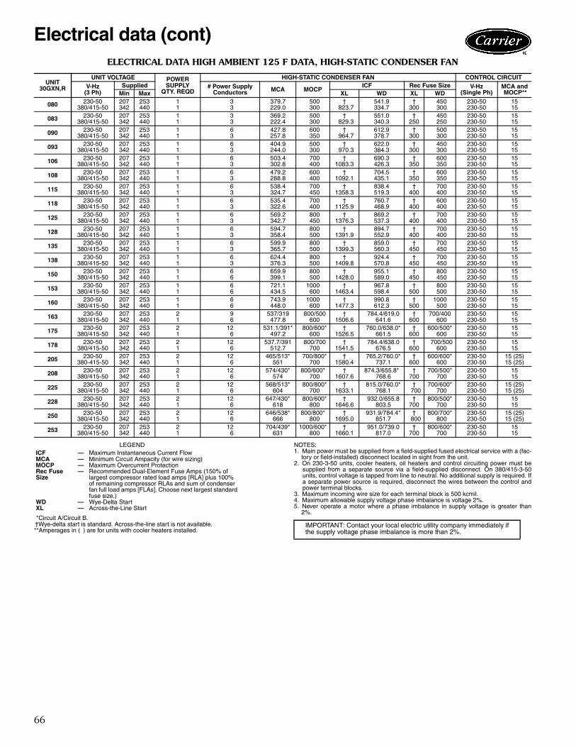
66
ELECTRICAL DATA HIGH AMBIENT 125 F DATA, HIGH-STATIC CONDENSER FAN
LEGEND
*Circuit A/Circuit B.†Wye-delta start is standard. Across-the-line start is not available.**Amperages in ( ) are for units with cooler heaters installed.
NOTES:1. Main power must be supplied from a field-supplied fused electrical service with a (fac-
tory or field-installed) disconnect located in sight from the unit.2. On 230-3-50 units, cooler heaters, oil heaters and control circuiting power must be
supplied from a separate source via a field-supplied disconnect. On 380/415-3-50units, control voltage is tapped from line to neutral. No additional supply is required. Ifa separate power source is required, disconnect the wires between the control andpower terminal blocks.
3. Maximum incoming wire size for each terminal block is 500 kcmil.4. Maximum allowable supply voltage phase imbalance is voltage 2%.5. Never operate a motor where a phase imbalance in supply voltage is greater than
2%.
UNIT30GXN,R
UNIT VOLTAGE POWERSUPPLY
QTY. REQD
HIGH-STATIC CONDENSER FAN CONTROL CIRCUITV-Hz
(3 Ph)Supplied # Power Supply
Conductors MCA MOCPICF Rec Fuse Size V-Hz
(Single Ph)MCA andMOCP**Min Max XL WD XL WD
080 230-50 207 253 1 3 379.7 500 † 541.9 † 450 230-50 15380/415-50 342 440 1 3 229.0 300 823.7 334.7 300 300 230-50 15
083 230-50 207 253 1 3 369.2 500 † 551.0 † 450 230-50 15380/415-50 342 440 1 3 222.4 300 829.3 340.3 250 250 230-50 15
090 230-50 207 253 1 6 427.8 600 † 612.9 † 500 230-50 15380/415-50 342 440 1 3 257.8 350 964.7 378.7 300 300 230-50 15
093 230-50 207 253 1 6 404.9 500 † 622.0 † 450 230-50 15380/415-50 342 440 1 3 244.0 300 970.3 384.3 300 300 230-50 15
106 230-50 207 253 1 6 503.4 700 † 690.3 † 600 230-50 15380/415-50 342 440 1 3 302.8 400 1083.3 426.3 350 350 230-50 15
108 230-50 207 253 1 6 479.2 600 † 704.5 † 600 230-50 15380/415-50 342 440 1 3 288.8 400 1092.1 435.1 350 350 230-50 15
115 230-50 207 253 1 6 538.4 700 † 838.4 † 700 230-50 15380/415-50 342 440 1 3 324.7 450 1358.3 519.3 400 400 230-50 15
118 230-50 207 253 1 6 535.4 700 † 760.7 † 600 230-50 15380/415-50 342 440 1 3 322.6 400 1125.9 468.9 400 400 230-50 15
125 230-50 207 253 1 6 569.2 800 † 869.2 † 700 230-50 15380/415-50 342 440 1 3 342.7 450 1376.3 537.3 400 400 230-50 15
128 230-50 207 253 1 6 594.7 800 † 894.7 † 700 230-50 15380/415-50 342 440 1 3 358.4 500 1391.9 552.9 400 400 230-50 15
135 230-50 207 253 1 6 599.9 800 † 859.0 † 700 230-50 15380/415-50 342 440 1 3 365.7 500 1399.3 560.3 450 450 230-50 15
138 230-50 207 253 1 6 624.4 800 † 924.4 † 700 230-50 15380/415-50 342 440 1 3 376.3 500 1409.8 570.8 450 450 230-50 15
150 230-50 207 253 1 6 659.9 800 † 955.1 † 800 230-50 15380/415-50 342 440 1 6 399.1 500 1428.0 589.0 450 450 230-50 15
153 230-50 207 253 1 6 721.1 1000 † 967.8 † 800 230-50 15380/415-50 342 440 1 6 434.5 600 1463.4 598.4 500 500 230-50 15
160 230-50 207 253 1 6 743.9 1000 † 990.8 † 1000 230-50 15380/415-50 342 440 1 6 448.0 600 1477.3 612.3 500 500 230-50 15
163 230-50 207 253 2 9 537/319 800/500 † 784.4/619.0 † 700/400 230-50 15380/415-50 342 440 1 6 477.8 600 1506.6 641.6 600 600 230-50 15
175 230-50 207 253 2 12 531.1/391* 800/600* † 760.0/638.0* † 600/500* 230-50 15380/415-50 342 440 1 6 497.2 600 1526.5 661.5 600 600 230-50 15
178 230-50 207 253 2 12 537.7/391 800/700 † 784.4/638.0 † 700/500 230-50 15380/415-50 342 440 1 6 512.7 700 1541.5 676.5 600 600 230-50 15
205 230-50 207 253 2 12 465/513* 700/800* † 765.2/760.0* † 600/600* 230-50 15 (25)380-415-50 342 440 1 6 551 700 1580.4 737.1 600 600 230-50 15 (25)
208 230-50 207 253 2 12 574/430* 800/600* † 874.3/655.8* † 700/500* 230-50 15380/415-50 342 440 1 6 574 700 1607.6 768.6 700 700 230-50 15
225 230-50 207 253 2 12 568/513* 800/800* † 815.0/760.0* † 700/600* 230-50 15 (25)380/415-50 342 440 1 6 604 700 1633.1 768.1 700 700 230-50 15 (25)
228 230-50 207 253 2 12 647/430* 800/600* † 932.0/655.8 † 800/500* 230-50 15380/415-50 342 440 1 6 618 800 1646.6 803.5 700 700 230-50 15
250 230-50 207 253 2 12 646/538* 800/800* † 931.9/784.4* † 800/700* 230-50 15 (25)380/415-50 342 440 1 6 666 800 1695.0 851.7 800 800 230-50 15 (25)
253 230-50 207 253 2 12 704/439* 1000/600* † 951.0/739.0 † 800/600* 230-50 15380/415-50 342 440 1 6 631 800 1660.1 817.0 700 700 230-50 15
ICF — Maximum Instantaneous Current FlowMCA — Minimum Circuit Ampacity (for wire sizing)MOCP — Maximum Overcurrent ProtectionRec FuseSize
— Recommended Dual-Element Fuse Amps (150% oflargest compressor rated load amps [RLA] plus 100%of remaining compressor RLAs and sum of condenserfan full load amps [FLAs]. Choose next largest standardfuse size.)
WD — Wye-Delta StartXL — Across-the-Line Start
IMPORTANT: Contact your local electric utility company immediately ifthe supply voltage phase imbalance is more than 2%.
Electrical data (cont)

67
ELECTRICAL DATA HIGH AMBIENT 125 F DATA, HIGH-STATIC CONDENSER FAN (cont)
LEGEND
*Circuit A/Circuit B.†Wye-delta start is standard. Across-the-line start is not available.**Amperages in ( ) are for units with cooler heaters installed.
NOTES:1. Main power must be supplied from a field-supplied fused electrical service with a
(factory or field-installed) disconnect located in sight from the unit.2. On 230-3-50 units, cooler heaters, oil heaters and control circuiting power must be
supplied from a separate source via a field-supplied disconnect. On 380/415-3-50units, control voltage is tapped from line to neutral. No additional supply is required. Ifa separate power source is required, disconnect the wires between the control andpower terminal blocks.
3. Maximum incoming wire size for each terminal block is 500 kcmil.4. Maximum allowable supply voltage phase imbalance is voltage 2%.5. Never operate a motor where a phase imbalance in supply voltage is greater than
2%.
UNIT30GXN,R
UNIT VOLTAGE POWERSUPPLY
QTY. REQD
HIGH-STATIC CONDENSER FAN CONTROL CIRCUITV-Hz
(3 Ph)Supplied # Power Supply
Conductors MCA MOCPICF Rec Fuse Size V-Hz
(Single Ph)MCA andMOCP**Min Max XL WD XL WD
264 230-50 207 253 2 12 704/538* 1000/800* † 950.9/784.4* † 800/700* 230-50 15 (25)380/415-50 342 440 1 6 700 800 1729.7 864.7 800 800 230-50 15 (25)
268 230-50 207 253 2 12 704/586* 1000/800* † 951.0/739.0* 800/600* 230-50 15380/415-50 342 440 1 6 731 800 1759.6 894.6 800 800 230-50 15
281 380/415-50 342 440 1 6 754 800 1783.4 918.4 1000 1000 230-50 15 (25)301 380/415-50 342 440 2 9 365/482* 500/600* 1394.5/1511.3* 529.5/646.3* 450/600* 450/600* 230-50 15 (25)325 380/415-50 342 440 2 12 390/506* 500/600* 1418.9/1535.7* 553.9/670.7* 450/600* 450/600* 230-50 15 (25)350 380/415-50 342 440 2 12 424/541* 600/700* 1453.5/1570.3* 588.5/705.3* 500/600* 500/600* 230-50 15 (25)
ICF — Maximum Instantaneous Current FlowMCA — Minimum Circuit Ampacity (for wire sizing)MOCP — Maximum Overcurrent ProtectionRec Fuse Size — Recommended Dual-Element Fuse Amps (150% of
largest compressor rated load amps [RLA] plus 100%of remaining compressor RLAs and sum of condenserfan full load amps [FLAs]. Choose next largest standardfuse size.)
WD — Wye-Delta StartXL — Across-the-Line Start
IMPORTANT: Contact your local electric utility company immediately ifthe supply voltage phase imbalance is more than 2%.

68
ELECTRICAL DATA HIGH AMBIENT 125 F DATA, DUPLEX UNITS (High Static Condenser Fan)
LEGEND
*Circuit A/Circuit B.†Wye-delta start is standard. Across-the-line start is not available.**Amperages in ( ) are for units with cooler heaters installed.
NOTES:1. Main power must be supplied from a field-supplied fused electrical service with a
(factory or field-installed) disconnect located in sight from the unit.2. On 230-3-50 units, cooler heaters, oil heaters and control circuiting power must be
supplied from a separate source via a field-supplied disconnect. On 380/415-3-50units, control voltage is tapped from line to neutral. No additional supply is required. Ifa separate power source is required, disconnect the wires between the control andpower terminal blocks.
3. Maximum incoming wire size for each terminal block is 500 kcmil.4. Maximum allowable supply voltage phase imbalance is voltage 2%.5. Never operate a motor where a phase imbalance in supply voltage is greater than
2%.
UNIT30GXN,R
UNIT VOLTAGE POWERSUPPLY
QTY. REQD
HIGH-STATIC CONDENSER FAN CONTROL CIRCUITV-Hz
(3 Ph)Supplied # Power Supply
Conductors MCA MOCPICF Rec Fuse Size V-Hz
(Single Ph)MCA andMOCP**Min Max XL WD XL WD
220B 230-50 207 253 1 6 427.8 600 † 612.9 † 500 230-50 15380/415-50 342 440 1 3 257.8 350 964.7 378.7 300 300 230-50 15
240B 230-50 207 253 1 6 538.4 700 † 838.4 † 700 230-50 15380/415-50 342 440 1 3 324.7 450 1358.3 519.3 400 400 230-50 15
220A, 240A 230-50 207 253 1 6 569.2 800 † 869.2 † 700 230-50 15380/415-50 342 440 1 3 342.7 450 1376.3 537.3 400 400 230-50 15
275A/B, 300B,365B, 395B
230-50 207 253 1 6 599.9 800 † 859.0 † 700 230-50 15380/415-50 342 440 1 3 365.7 500 1399.3 560.3 450 450 230-50 15
283B, 303B,373B
230-50 207 253 1 6 624.4 800 † 924.4 † 700 230-50 15380/415-50 342 440 1 3 376.3 500 1409.8 570.8 450 450 230-50 15
283A, 328B,393B, 418B
230-50 207 253 1 6 721.1 1000 † 967.8 † 800 230-50 15380/415-50 342 440 1 6 434.5 600 1463.4 598.4 500 500 230-50 15
303A 230-50 207 253 2 9 537.7/319* 800/500* † 784.4/619.0* † 700/400* 230-50 15380/415-50 342 440 1 6 477.8 600 1506.6 641.6 600 600 230-50 15
328A, 353A,353B
230-50 207 253 2 12 537.7/391* 800/700* † 784.4/638.0* † 700/500* 230-50 15380/415-50 342 440 1 6 512.7 700 1541.5 676.5 600 600 230-50 15
300A, 320A/B 230-50 207 253 1 6 743.9 1000 † 990.8 † 1000 230-50 15380/415-50 342 440 1 6 448.0 600 1477.3 612.3 500 500 230-50 15
345A/B 230-50 207 253 2 12 531.1/391* 800/600* † 760.0/638.0* † 600/500* 230-50 15380/415-50 342 440 1 6 497.2 600 1526.5 661.5 600 600 230-50 15
410B 230-50 207 253 2 12 465/513* 700/800* † 765.2/760.0* † 600/600* 230-50 15 (25)380-415-50 342 440 1 6 551 700 1580.4 737.1 600 600 230-50 15 (25)
410A, 440A/B,470B
230-50 207 253 2 12 568/513* 800/800* † 815.0/760.0* † 700/600* 230-50 15 (25)380/415-50 342 440 1 6 604 700 1633.1 768.1 700 700 230-50 15 (25)
365A, 470A,495A/B
230-50 207 253 2 12 646/481* 800/700* † 931.9/728.0* † 800/600* 230-50 15 (25)380/415-50 342 440 1 6 617 800 1646.6 8032 700 700 230-50 15 (25)
395A, 520A/B 230-50 207 253 2 12 704/538* 1000/800* † 950.9/784.4* † 800/700* 230-50 15 (25)380/415-50 342 440 1 6 700 800 1729.7 864.7 800 800 230-50 15 (25)
453A, 453B,478B
230-50 207 253 2 12 647/430* 800/600* † 932.0/655.8* † 800/500* 230-50 15380/415-50 342 440 1 6 618 800 1646.6 803.5 700 700 230-50 15
373A, 393A, 478A,503A, 503B
230-50 207 253 2 12 704/439* 1000/600* † 951.0/739.0* † 800/600* 230-60 15380/415-50 342 440 1 6 631 800 1660.1 817.0 700 700 230-60 15
418A, 528A,528B
230-50 207 253 2 12 704/586* 1000/800* † 951.0/833.2* † 800/700* 230-50 15380/415-50 342 440 1 6 731 800 1759.6 894.6 800 800 230-50 15
ICF — Maximum Instantaneous Current FlowMCA — Minimum Circuit Ampacity (for wire sizing)MOCP — Maximum Overcurrent ProtectionRec Fuse Size — Recommended Dual-Element Fuse Amps (150% of
largest compressor rated load amps [RLA] plus 100%of remaining compressor RLAs and sum of condenserfan full load amps [FLAs]. Choose next largest standardfuse size.)
WD — Wye-Delta StartXL — Across-the-Line Start
IMPORTANT: Contact your local electric utility company immediately ifthe supply voltage phase imbalance is more than 2%.
Electrical data (cont)

69
The standard microprocessor-based control in the30GXN,R units provides the following functions:• leaving fluid temperature control (using both entering
and leaving fluid sensors)• 7-day time sequence of both pump and chiller• temperature reset from return fluid (standard) or from
outdoor ambient, occupied space temperature, 4 to20 mA signal, or via the optional Carrier Comfort Net-work (CCN).
• automatic compressor lead-lag switching based on com-pressor accumulated run times and number of cycles.
• automatic temperature range across the cooleradjustment
• fully automatic control of the chiller componentsA 4-line, 20-character per line display is used to accom-plish the following (see figure below):• perform service test procedures• set schedules and set points• identify operating mode and run status conditions• display current temperatures and pressures being used
by the control for internal calculations• identify abnormal (alarm or alert) conditions• configure unit operation
Sequence of operationThe control has a 44.0 F (6.2 C) leaving fluid temperature(LWT) set point as shipped from the factory. If temperaturereset or demand limiting is in effect, this set point maychange.Start-up — The chiller start when the circulating pump isenergized and the flow has been proven. The compressorstarts unloaded.NOTE: The starting compressor is determined by the auto-matic lead/lag feature.
If the entering fluid temperature is 85 F (29 C) or higherand the saturated suction temperature is 50 F (10 C) orhigher, the maximum operating pressure (MOP) featurelimits the suction pressure to keep the chiller on line.Normal operation — The entering fluid temperaturesensor senses changes in entering fluid temperature toanticipate changes in the cooling load. Based on leavingfluid temperature, the control will add or delete capacity tomaintain a constant leaving fluid temperature.Transition to off — The chiller unloads once the “time-to-stop” signal has been given. This signal can be eitherinternal or external (remote).Safeties — The 30GXN,R control as shipped from thefactory automatically deenergizes any active compressorthat experiences any of the following:• electrical overload• thermal overload protection• high pressure• low oil pressure• loss of refrigerant charge• loss of phase protection• reverse rotation (control prevents compressor start)• current imbalance• ground current fault• low chilled fluid temperature• loss of chilled water flow
Additional informationDetailed information on controls and operation is availablein the Controls, Start-Up, Operation and Troubleshootingguide included with each unit. Packaged Service Trainingprograms are also available. Contact your Carrier repre-sentative for more information.Dual chiller control — The ComfortLink™ controllerallows 2 chillers (piped in series or parallel) to operate as asingle chilled water plant with standard control functionscoordinated through the master chiller controller. Thisstandard ComfortLink feature requires a communicationlink between the 2 chillers and an additional thermistor forparallel operation.ECOLOGIC η, ECOLOGIC™ control — ECOLOGICand ECOLOGIC η control keeps the chiller on line duringperiods of extreme operating conditions. If the enteringfluid temperature is 85 F (29 C) or higher and the saturatedsuction temperature is 50 F (10 C) or higher the maximumoperating pressure (MOP) feature limits the suction to keepthe chiller online. The control automatically starts thechiller in the unloaded state to eliminate the potential ofcompressor overload due to high head pressure or lowsuction pressure. The controller will equalize run time oneach circuit through the lead/lag feature. If a circuitbecomes disabled, the control will automatically set theactive circuit to lead, keeping the chiller online at a reducedcapacity.
Controls
Run StatusService TestTemperaturesPressures
SetpointsInputs
OutputsConfigurationTime Clock
Operating ModesAlarms
ENTER
E S C
M O D EAlarm Status
TIMEEWTLWTSETP
1 2 . 5 85 4 . 6 ° F4 4 . 0 ° F4 4 . 0 ° F
N A V I G A T O R ™
C o m f o r t L i n k
NAVIGATOR DISPLAY MODULE — STANDARD

70
Typical control wiring schematic
LEGENDA — AlarmCWP — Chilled Water PumpCWPI — Chilled Water Pump InterlockEMM — Energy Management ModuleFIOP — Factory-Installed OptionLWT — Leaving Water ThermistorOAT — Outdoor-Air ThermistorSPT — Space Temperature ThermistorTB — Terminal Block
Field WiringField Control WiringFactory-Installed Wiring
NOTES:1. Factory wiring is in accordance with National Electrical Code (NEC) U.S.A. only. Field modifications or
additions must be in compliance with all applicable codes.2. Wiring for main field power supply must be rated 75° C minimum. Use copper conductors for all units.
Maximum incoming wire size for each terminal block is 500 kcmil.3. Power for control circuit should be supplied from a separate source (except 380/415-v units) through a
field-supplied disconnect with 15-amp maximum protection for 230-volt control circuit. Connect controlcircuit power to terminals 1 and 2 of TB4. Control circuit conductors for all units must be copper only.Control circuit power is factory wired for 380/415-v units. If a separate power source is required, discon-nect the wires between the power terminal block and the control terminal block.
4. Terminals 13 and 14 of TB5 are for field external connection for remote on-off. The contacts must berated for dry circuit application capable of handling a 24-vac load up to 50 mA.
5. Terminals 1 and 2 of TB5 are for Chilled Water Pump Interlock (CWPI) functions. If added, chilled waterpump interlock contacts must be wired in series with flow switch contacts. The contacts must be rated fordry circuit application capable of handling a 24-vac load up to 50 mA load. Chilled Water Flow Switch(CWFS) is factory installed.
6. Terminals 10 and 12 of TB5 are for control of chilled water pump starter. The maximum load allowed forthe chilled water pump relay is 75-va sealed, 360-va inrush at 230 volt. Field power supply is notrequired.
7. Terminals 11 and 12 of TB5 are for alarm relay. The maximum load allowed for the alarm relay is 75-vasealed, 360-va inrush at 230 volt. Field power supply is not required.
8. Make appropriate connections to TB6 as shown for energy management board options. The contacts forDemand Limit and Ice Done options must be rated for dry circuit application capable of handling a 24-vacload up to 50 mA.

71
Leveling unitUnit must be level within 1/8 in. per ft (1 cm per meter)when installed to ensure proper oil return to thecompressor.
While most outdoor locations are suitable for 30GXN,Runits, the roof is a common site that represents a problemif roof has been pitched to aid in water removal. To assureproper oil return, be sure that unit is level, particularly in itsmajor lengthwise dimension, as compressor oil return pip-ing runs in that direction.
It should be determined prior to installation if any spe-cial treatment is required to assure a level installation.Piping duplex units — 30GXN,R Duplex Chillers areshipped and rigged as 2 separate units. The units must bepiped in series. Module A must be placed on the returnside, Module B should be placed on the leaving chilled fluidside. Minimum spacing of 36-in. (914.4 mm) between chill-ers is recommended to provide adequate service access andpiping clearance. If the accessory trim kit is used; themodules must be aligned according to the criteria given inthe accessory installation instruction. A flexible pipecoupling should be used to allow for module misalignment.Grooved pipe fittings are recommended for use on theinterconnecting piping to allow maintenance (cooler tubecleaning) access and to avoid excessive weld slag formbeing flushed through the cooler during initial start-up.
Cooler fluid temperature1. Maximum leaving chilled-fluid temperature (LCWT) is
60 F (21 C). Unit can start and pull down with up to95 F (35 C) entering-fluid temperature due to MOP(maximum operating pressure) feature of the expansionvalve. For sustained operation, it is recommended thatentering fluid temperature not exceed 70 F (21.1 C).
2. Minimum LCWT is 40 F (4.4 C) for standard units.Optional brine units are required for operation withleaving fluid temperatures in the range of 40 to 15 F(4.4 to –9 C). For ratings below 40 F (4.4 C) LCWT,contact your local Carrier representative.
3. Minimum entering chilled-fluid temperature (ECWT)is 45 F (7.2 C). Maximum ECWT is 70 F (21.1 C).
Leaving-fluid temperature resetThe accessory reset sensor can be applied to the chiller toprovide reset of LCWT in constant fluid flow systems.Reset reduces compressor power usage at part load whendesign LCWT is not necessary. Note that resetting LCWTmay affect other air-conditioning system components. Forexample, humidity control should be considered, sincehigher coil temperatures resulting from reset will reducelatent heat capacity of air handlers and fan coils in the air-conditioning system. Three reset applications are offered: From return-fluid temperature — Increases LCWT setpoint as return (or entering) fluid temperature decreases(indicating load decrease). Option may be used in anyapplication where return fluid provides accurate load indi-cation. Limitation of return-fluid reset is that the LCWTmay only be reset to value of design return-fluid tempera-ture. No additional hardware is required.
From outdoor-air temperature — Increases LCWT asoutdoor ambient temperature decreases (indicating loaddecrease). This reset should be applied only where outdoorambient temperature is an accurate indication of load. Afield-supplied thermistor is required.From occupied space temperature — IncreasesLCWT as space temperature decreases (indicating loaddecrease). This reset should be applied only where spacetemperature is an accurate indication of load. A field-supplied thermistor is required.
Cooler temperature riseRatings and performance data in this publication are for acooling temperature rise of 10° F (5.6° C). Units may beoperated at a different temperature rise, provided flowlimits are not exceeded and corrections to capacity, etc.,are made. For minimum flow rates, see the Unit OperatingRanges table. High flow rate is limited by pressure dropthat can be tolerated. If another temperature rise is used,apply LCWT correction as given in the Carrier electroniccatalog 30GXN,R chiller program.Minimum cooler flow — Flow (maximum cooler tem-perature rise) for standard units is shown in the Unit Oper-ating Ranges table. Maximum change in temperature is20° F (11.1° C). When flow rate required is lower (or rise ishigher), follow recommendations below:• Multiple smaller chillers can be applied in series, each
providing a portion of the design temperature rise.• Some chilled fluid can be recirculated through the cooler
to raise flow rate. However, mixed temperature enteringcooler must be maintained at a minimum of at least 5° F(2.8° C) above the leaving chilled fluid temperature.
• Special reduced pass or multiple pass heads cooler canbe used. Contact your Carrier representative for furtherinformation.
NOTE: Recirculation flow is shown below.
Application data
RECIRCULATION FLOW

72
Maximum cooler flow (> 5 gpm/ton or < 5° F rise[> 0.09 L/s • kW or 2.7° C rise]) — Maximum flowresults in practical maximum pressure drop through cooler.
Return fluid can bypass the cooler to keep pressure dropthrough cooler within acceptable limits. This permits ahigher ∆T with lower fluid flow through cooler and mixingafter the cooler. Contact your Carrier representative ifpressure drop appears excessive.NOTE: Bypass flow is shown below.
Variable cooler flow rates — These variable flow ratesmay be applied to standard 30GXN,R series chillers. Theunit will attempt to maintain a constant leaving chilled-fluidtemperature. In such cases, minimum fluid volume must bein excess of 3 gal per ton (3.23 L per kW) and flow ratemust change in steps of less than 10% per minute. Apply6 gal per ton (6.5 L per kW) fluid loop volume minimum ifflow rate changes more rapidly.Chilled fluid loop volume — The chilled fluid loopvolume in circulation must equal or exceed 3 gal per nomi-nal ton of cooling (3.23 L per kW) for temperature stabilityand accuracy in normal air conditioning applications.For example, a 30GXN,R106 with a nominal capacity of97.5 tons (342.8 kW) would require 292.5 gal (1106 L) incirculation in the system loop.
For process jobs where accuracy is vital, or for operationat ambient temperatures below 32 F (0° C) with low unitloading conditions, there should be from 6 to 10 gal perton (6.5 to 10.8 L per kW). To achieve this volume, it is of-ten necessary to install a tank in the loop. Tank should bebaffled to ensure there is no stratification, and that water(or brine) entering tank is adequately mixed with liquid inthe tank. See below.
Fouling factor — The factor used to calculate tabulated rat-ings was 0.00010 ft2 • hr • F/Btu (.000018 m2 • °C/W). Asfouling factor is increased, unit capacity decreases and com-pressor power increases. To determine selections at other foul-ing factors, use the chiller program in the electronic catalog.
High ambient temperatureHigh outdoor ambient chiller start-up and operation (fullyloaded) is possible for standard 30GXN,GXR chillers at ambi-ent temperatures up to 125 F (52 C) at nominal voltage. Insome cases, where return water temperature is expected toexceed 60 F (15.5 C), an accessory kit may be required.
Low ambient temperature operationWith certain field provisions as described below, units willstart and operate down to —
0° F (–18 C) for 30GXN,R080-16315 F (–9 C) for 30GXN,R175-528If operation is intended below these limits, the Carrier
accessory Motormaster® condenser head pressure controland its associated components must be added. The Motor-master control allows operation down to –20 F (–29 C).Consult your Carrier representative for details.NOTE: Minimum load on chiller must be above minimumstep of unloading.Wind baffles (field-installed accessory) — Bafflesmust be added to all units for operation below 32 F (0° C)if wind velocity is anticipated to be greater than 5 mph(8 km/h).Cooler freeze protection — If chiller refrigerant or fluidlines are in an area where ambient conditions fall below32 F (0° C), it is required that an antifreeze solution beadded to protect the unit and fluid piping to a temperature15° F (8.3° C) below the lowest anticipated temperature.For corrections to performance, refer to the chiller pro-gram in the electronic catalog.
Use only antifreeze solutions approved for heat ex-changer duty. Use of automotive antifreezes is not recom-mended because of the fouling that can occur once theirrelatively short-lived inhibitors break down.
Select concentration based on either Burst or FreezeProtection as dictated by application. Additional freezeprotection is available through the use of the low ambientprotection option. Since power is sometimes lost for ex-tended periods during winter storms (particularly in subur-ban and rural areas) freeze protection will only be effectiveif back-up power supply can be assured for the unit’s con-trol circuit, heater and cooler pump.
If not protected with an antifreeze solution, drainingcooler and outdoor piping is recommended if system willnot be used during freezing weather conditions.
Oversizing chillersOversizing chillers by more than 15% at design conditionsmust be avoided as the system operating efficiency will be
IMPORTANT: Adding antifreeze solution is the onlycertain means of protecting the unit from freeze-up ifthe cooler heater fails or electrical service is interruptedduring low ambient temperatures.
Application data (cont)
BYPASS FLOW
TANK INSTALLATION
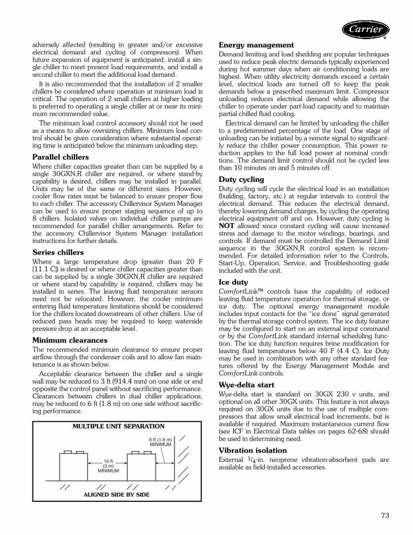
73
adversely affected (resulting in greater and/or excessiveelectrical demand and cycling of compressors). Whenfuture expansion of equipment is anticipated, install a sin-gle chiller to meet present load requirements, and install asecond chiller to meet the additional load demand.
It is also recommended that the installation of 2 smallerchillers be considered where operation at minimum load iscritical. The operation of 2 small chillers at higher loadingis preferred to operating a single chiller at or near its mini-mum recommended value.
The minimum load control accessory should not be usedas a means to allow oversizing chillers. Minimum load con-trol should be given consideration where substantial operat-ing time is anticipated below the minimum unloading step.
Parallel chillersWhere chiller capacities greater than can be supplied by asingle 30GXN,R chiller are required, or where stand-bycapability is desired, chillers may be installed in parallel.Units may be of the same or different sizes. However,cooler flow rates must be balanced to ensure proper flowto each chiller. The accessory Chillervisor System Managercan be used to ensure proper staging sequence of up to8 chillers. Isolated valves on individual chiller pumps arerecommended for parallel chiller arrangements. Refer tothe accessory Chillervisor System Manager installationinstructions for further details.
Series chillers Where a large temperature drop (greater than 20 F[11.1 C]) is desired or where chiller capacities greater thancan be supplied by a single 30GXN,R chiller are requiredor where stand-by capability is required, chillers may beinstalled in series. The leaving fluid temperature sensorsneed not be relocated. However, the cooler minimumentering fluid temperature limitations should be consideredfor the chillers located downstream of other chillers. Use ofreduced pass heads may be required to keep watersidepressure drop at an acceptable level.
Minimum clearancesThe recommended minimum clearance to ensure properairflow through the condenser coils and to allow fan main-tenance is as shown below.
Acceptable clearance between the chiller and a singlewall may be reduced to 3 ft (914.4 mm) on one side or endopposite the control panel without sacrificing performance.Clearances between chillers in dual chiller applications,may be reduced to 6 ft (1.8 m) on one side without sacrific-ing performance.
Energy managementDemand limiting and load shedding are popular techniquesused to reduce peak electric demands typically experiencedduring hot summer days when air conditioning loads arehighest. When utility electricity demands exceed a certainlevel, electrical loads are turned off to keep the peakdemands below a prescribed maximum limit. Compressorunloading reduces electrical demand while allowing thechiller to operate under part-load capacity and to maintainpartial chilled fluid cooling.
Electrical demand can be limited by unloading the chillerto a predetermined percentage of the load. One stage ofunloading can be initiated by a remote signal to significant-ly reduce the chiller power consumption. This power re-duction applies to the full load power at nominal condi-tions. The demand limit control should not be cycled lessthan 10 minutes on and 5 minutes off.
Duty cyclingDuty cycling will cycle the electrical load in an installation(building, factory, etc.) at regular intervals to control theelectrical demand. This reduces the electrical demand,thereby lowering demand charges, by cycling the operatingelectrical equipment off and on. However, duty cycling isNOT allowed since constant cycling will cause increasedstress and damage to the motor windings, bearings, andcontrols. If demand must be controlled the Demand Limitsequence in the 30GXN,R control system is recom-mended. For detailed information refer to the Controls,Start-Up, Operation, Service, and Troubleshooting guideincluded with the unit.
Ice dutyComfortLink™ controls have the capability of reducedleaving fluid temperature operation for thermal storage, orice duty. The optional energy management moduleincludes input contacts for the “ice done” signal generatedby the thermal storage control system. The ice duty featuremay be configured to start on an external input commandor by the ComfortLink standard internal scheduling func-tion. The ice duty function requires brine modification forleaving fluid temperatures below 40 F (4.4 C). Ice Dutymay be used in combination with any other standard fea-tures offered by the Energy Management Module andComfortLink controls.
Wye-delta startWye-delta start is standard on 30GX 230 v units, andoptional on all other 30GX units. This feature is not alwaysrequired on 30GX units due to the use of multiple com-pressors that allow small electrical load increments, but isavailable if required. Maximum instantaneous current flow(see ICF in Electrical Data tables on pages 62-68) shouldbe used in determining need.
Vibration isolationExternal 1/4-in. neoprene vibration-absorbent pads areavailable as field-installed accessories.
10 ft(3 m)
MINIMUM
6 ft (1.8 m)MINIMUM
MULTIPLE UNIT SEPARATION
ALIGNED SIDE BY SIDE
74
StrainersA strainer with a minimum screen size of 20 mesh must beinstalled in the entering cooler fluid line, 10 ft (3.3 m)ahead of the cooler.
Condenser coil corrosion protection (Enviro-Shield™)Pre-coated aluminum-fin coils have a durable epoxy-phenolic coating applied to the fin prior to the fin stampingprocess to provide protection in mildly corrosive coastalenvironments. Pre-coated coils have an inert barrierbetween the aluminum fin and copper tube. This barrierelectrically disconnects the dissimilar metals to minimizethe potential for galvanic corrosion. This economicaloption provides substantial corrosion protection beyondthe standard uncoated coil construction.Copper-fin coils provide increased corrosion resistancein moderate coastal environments where industrial air pol-lution is not present. All copper coils eliminate bi-metallicconstruction to eliminate the potential for galvanic corro-sion. Application in industrial environments is not rec-ommended due to potential attack from sulfur, sulfur oxide,nitrogen oxides, carbon and several other industrial air-borne contaminants. In moderate seacoast environments,copper-fin coils have extended life compared to standardor pre-coated aluminum-fin coils.
E-coated aluminum-fin coils have a extremely flexibleand durable epoxy coating uniformly applied to all coilsurfaces. Unlikely brittle phenolic dip and bake coatings,E-coat provides superior protection with unmatched flexi-bility, edge coverage, metal adhesion, thermal perfor-mance and most importantly, corrosion resistance.E-coated coils provide this protection since all coil surfacesare completely encapsulated from environmental contami-nation. Specify E-coated aluminum-fin coils for industrialenvironments with high levels of air pollution. This optionalso provides better protection compared to standard orpre-coated aluminum-fin coils in industrial environments.E-coated copper-fin coils have the same flexible anddurable epoxy coating as E-coated aluminum-fin coils.However, this option combines the natural salt and envi-ronment resistance of all-copper construction with thehighest level of corrosion protection. Specify E-coatedcopper-fin coils in the harshest combination of coastal andindustrial environments.
Operating efficiencyChiller full load operating efficiency is directly related to theannual operating cost of the machine. An increase inchiller efficiency can have a very dramatic impact onannual operating expense.
Application data (cont)

75
Air-Cooled Liquid ChillerHVAC Guide SpecificationsSize Range: 80 to 525 Tons (267 to 1750 kW) Nominal (50 Hz)Carrier Model Number: 30GXN, GXRPart 1 — General1.01 SYSTEM DESCRIPTION
Microprocessor controlled, air-cooled liquid chillerutilizing HFC-134a, screw compressors, and elec-tronic expansion devices.
1.02 QUALITY ASSURANCEA. Unit shall be rated in accordance with ARI Standard
550/590, latest revision (U.S.A.).B. Unit construction shall comply with ASHRAE 15
Safety Code, NEC, and ASME applicable codes(U.S.A. codes).
C. Unit shall be manufactured in a facility registered toISO 9001:2000 Manufacturing Quality Standard.
D. Unit shall be full load run tested at the factory.1.03 DELIVERY, STORAGE AND HANDLING
A. Unit controls shall be capable of withstanding150 F (66 C) storage temperatures in the controlcompartment.
B. Unit shall be stored and handled per unit manufac-turer's recommendations.
Part 2 — Products2.01 EQUIPMENT
A. General:Factory assembled, single-piece or factory config-ured duplex chassis, air-cooled liquid chiller. Con-tained within the unit cabinet shall be all factorywiring, piping, controls, refrigerant charge(HFC-134a), and special features required prior tofield start-up.
B. Efficiency:Chiller shall have a minimum full load operating effi-ciency of _____ EER as rated in accordancewith and certified per ARI 550/590-98 (U.S.A.Standard).
C. Unit Cabinet:1. Frame shall be of heavy-gage galvanized steel.2. Cabinet shall be galvanized steel casing with a
pre-painted finish.3. Cabinet shall be capable of withstanding
500-hour salt spray test in accordance with theASTM (U.S.A.) B-117 standard.
D. Fans:1. Condenser fans shall be direct-driven, 11-blade
airfoil cross-section, reinforced polymer con-struction, shrouded-axial type, and shall be stat-ically and dynamically balanced with inherentcorrosion resistance. Air shall be dischargedvertically upward.
2. Fans shall be protected by coated steel wiresafety guards.
E. Compressors:1. Unit shall have semi-hermetic twin-screw, gear-
driven compressors with internal muffler andcheck valve.
2. Each compressor shall be equipped with a dis-charge shutoff valve.
3. Capacity control shall be provided by pilot-operated solenoid valve, capable of reducingunit capacity to 10% of full load. Compressorshall start in unloaded condition.
4. Motor cooling shall be provided by direct liquidinjection and protected internal overloadthermistor.
5. Lube oil system shall include pre-filter and inter-nal filter capable of filtration to 4 microns.
6. Rubber-in-shear isolation.F. Cooler:
1. Cooler shall be tested and stamped in accor-dance with ASME code (U.S.A.) for a refrigerantworking-side pressure of 220 psig (1517 kPa)and shall be tested for a maximum fluid-sidepressure of 300 psig (2068 kPa) (in Canada,250 psig [1724 kPa] per Canadian NationalRegistry requirements).
2. Shall be mechanically cleanable shell-and-tubetype with removable heads.
3. Tubes shall be internally enhanced, seamless-copper type, and shall be rolled into tube sheets.
4. Shall be equipped with mechanical groovedVictaulic-type fluid connections.
5. Shell shall be insulated with 3/4-in. (19 mm)closed-cell, polyvinyl-chloride foam with a maxi-mum K factor of 0.28.
6. Shall incorporate 2 independent refrigerantcircuits.
7. Shall have a cooler drain and vent.8. Shall incorporate a refrigerant level sensing
device.9. Low Ambient Protection: Unit shall have fac-
tory-installed head-mounted cooler heater,liquid line solenoid vales and pumpout cycle toprotect cooler from ambient temperature freezedown to 0° F (–17 C).
G. Condenser:1. Coil shall be air-cooled with integral subcooler,
and shall be constructed of aluminum finsmechanically bonded to seamless copper tubes.The tubes are then cleaned, dehydrated, andsealed.
2. Condenser coils shall be leak tested and shall bepressure tested at 450 psig (3103 kPa).
3. Refrigeration Components: Refrigerant circuitcomponents shall include oil separator, highand low side pressure relief device, dischargeand liquid line shutoff valves, filter drier, mois-ture indicating sight glass, electronic expansiondevice, refrigerant economizer (size 106-528units), and complete operating charge of bothrefrigerant HFC-134a and compressor oil.
Guide specifications

76
4. The chiller shall include the ability to isolate therefrigerant charge in either the cooler or thecondenser.
H. Controls, Safeties, and Diagnostics:1. Controls:
a. Unit controls shall include the following min-imum components:
1) Microprocessor with non-volatile mem-ory. Battery backup system shall not beaccepted.
2) Power and control circuit terminalblocks.
3) ON/OFF control switch.4) Replaceable solid-state relay panels.5) Thermistor installed to measure satu-
rated condensing temperature, coolersaturation temperature, compressorreturn gas temperature, and coolerentering and leaving fluid temperatures.
b. Unit controls shall include the followingfunctions as standard:
1) Automatic circuit lead/lag.2) Capacity control based on leaving
chilled fluid temperature and compen-sated by rate of change of return-fluidtemperature with temperature set pointaccuracy to 0.1° F (0.06° C).
3) Limiting the chilled fluid temperaturepull-down rate at start-up to an adjust-able range of 0.2° F to 2° F (0.11° C to1.1° C) per minute to prevent excessivedemand spikes at start-up.
4) Seven-day time schedule.5) Leaving chilled fluid temperature reset
from return fluid, outdoor-air tempera-ture, space temperature, or 4 to 20 mAinput.
6) Demand limit control with 2-stage con-trol (0 to 100% each) or through 4 to20 mA input (0 to 100%).
7) Chilled water pump start/stop control.8) Dual chiller control for series chiller
applications without addition of hard-ware modules or additional thermistors.
9) Amperage readout per compressor with%MTA per compressor.
10) Auto-restart after power failure.c. The control panel shall include, as standard,
a portable hand held display module with aminimum of 4 lines and 20 characters perline, of clear English, Spanish, Portuguese orFrench language. Display menus shall pro-vide clear language descriptions of all menuitems, operating modes, configurationpoints and alarm diagnostics. Reference tofactory codes shall not be accepted. Anindustrial grade coiled extension cord shallallow the display module to be movedaround the chiller. Magnets shall hold thedisplay module to any sheet metal panel toallow hands-free operation. Display moduleshall have NEMA 4x housing suitable for use
in outdoor environments. Display shall haveback light and contrast adjustment for easyviewing in bright sunlight or night condi-tions. The display module shall have raisedsurface buttons with positive tactileresponse.
d. The chiller controller shall include multipleconnection ports for communicating withthe local equipment network, the CarrierComfort Network (CCN) and the ability toaccess all chiller control functions from anypoint on the chiller.
e. The control system shall allow software up-grade without the need for new hardwaremodules.
2. Safeties:a. Unit shall be equipped with thermistors and
all necessary components in conjunctionwith the control system to provide the unitwith the following protections:
1) Loss of refrigerant charge.2) Reverse rotation.3) Low chilled fluid temperature.4) Low oil pressure (each compressor
circuit).5) Voltage imbalance.6) Ground current fault.7) Thermal overload.8) High pressure.9) Electrical overload.
10) Loss of phase.11) Current imbalance.12) Loss of chilled water flow.
b. Fan motors shall have inherent overcurrentprotection.
3. Diagnostics:a. The display module shall be capable of indi-
cating the safety lockout condition by dis-playing the information in clear language atthe display. Information displayed shallinclude:
1) Compressor lockout.2) Loss of charge.3) Low fluid flow.4) Low oil pressure.5) Cooler freeze protection.6) High or low suction superheat.7) Thermistor malfunction.8) Entering and leaving-fluid temperature.9) Evaporator and condenser pressure.
10) Electronic expansion valve positions.11) All set points.12) Time of day.
Guide specifications (cont)

77
b. Display module, in conjunction with themicroprocessor, must also be capable of dis-playing the output results of a service test.Service test shall verify operation of everyswitch, thermistor, fan, and compressorbefore chiller is started. User shall be able toforce each output device.
c. Diagnostics shall include the ability to reviewa list of the 20 most recent alarms with clearlanguage descriptions of the alarm event.Display of alarm codes without the abilityfor clear language descriptions shall beprohibited.
d. An alarm history buffer shall allow the userto store no less than 20 alarm events withclear language descriptions, time and datestamp event entry.
I. Operating Characteristics:1. Unit shall be capable of starting and running at
outdoor ambient temperatures from 32 F to125 F (0° to 52 C) for 080-178 units and 15 to125 F (–11 to 52 C) for 205-525 units.
2. Unit shall be capable of starting up with 95 F(35 C) entering fluid temperature to the cooler.
J. Motors:Condenser-fan motors shall be totally enclosed3-phase type with permanently lubricated bearingsand Class F insulation.
K. Electrical Requirements:1. Unit primary electrical power supply shall enter
the unit at a single location (some units havemultiple poles).
2. Primary electrical power supply shall be rated towithstand 115 F (46 C) operating ambient asstandard or 125 F (52 C) optional.
3. Unit shall operate on 3-phase power at the volt-age shown in the equipment schedule.
4. Control voltage shall be 230 v, single-phase.5. Unit shall be shipped with factory control and
power wiring installed.L. Special Features:
Certain standard features are not applicable whenthe features designed by * are specified. For assis-tance in amending the specifications, contact yourCarrier Sales office.
1. Wye-Delta Starter:Unit shall have a factory-installed, wye-deltastart to minimize electrical inrush current.
* 2. Low-Ambient Operation:Unit shall be capable of starting and running atoutdoor ambient temperatures down to –20 F(–29 C) with the addition of antifreeze in thecooler circuit, wind baffles, and field- or factory-installed low-ambient kit.a. Factory-mounted or field-supplied low ambient
head pressure control shall be accomplishedvia electronic variable speed condenser fanmotor drive system.
3. Low Ambient Protection:Unit shall be supplied with factory mountedcooler head heaters and liquid line valves com-bined with a pumpdown cycle to provide coolerfreeze protection down to 0° F (–17.7 C).
4. Non-Fused Disconnect:Unit shall be supplied with factory-installed,non-fused electrical disconnect for main powersupply.
5. Loss-of-Flow Protection:Unit shall be supplied with factory-installedthermal dispersion type proof-of-flow sensingswitch.
6. Optional Condenser Coil Materials:a. Pre-coated aluminum-fin coils:
Shall have a durable epoxy-phenolic coatingto provide protection in mildly corrosivecoastal environments. Coating shall beapplied to the aluminum fin stock prior tothe fin stamping process to create an inertbarrier between the aluminum fin and cop-per tube. Epoxy-phenolic barrier shall mini-mize galvanic action between dissimilarmetals.
b. Copper-fin coils:Shall be constructed of copper fins mechani-cally bonded to copper tubes and coppertube sheets. Galvanized steel tube sheetsshall not be acceptable. A polymer strip shallprevent coil assembly from contacting sheetmetal coil pan to minimize potential for gal-vanic corrosion between the coil and pan.All copper construction shall provide protec-tion in moderate coastal environments.
c. E-Coat aluminum-fin coils:Shall have a flexible epoxy polymer coatinguniformly applied to all coil surface areaswithout material bridging between fins.Coating process shall ensure complete coilencapsulation. Color shall be high glossblack with gloss - 60° of 65-90% per ASTMID523-89 (U.S.A. Standard). Uniform dryfilm thickness from 0.8 to 1.2 mil on all sur-face areas including fin edges. Superiorhardness characteristics of 2H per ASTMD3363-92A (U.S.A. Standard) and crosshatch adhesion of 4B-5B per ASTMD3359-93 (U.S.A. Standard). Impact resis-tance shall be up to 160 in./lbs. (ASTMD2794-93, U.S.A. Standard). Humidity andwater immersion resistance shall be up tominimum 1000 and 250 hours respectively(ASTM D2247-92 and ASTM D870-92,U.S.A Standards). Corrosion durability shallbe confirmed through testing to no less than3000 hours salt spray per ASTM B117-90(U.S.A. Standard). Coil construction shall bealuminum fins mechanically bonded to cop-per tubes.

78
d. E-Coat copper-fin coils:Shall have a flexible epoxy polymer coatinguniformly applied to all coil surface areaswithout material bridging between fins.Coating process shall ensure complete coilencapsulation. Color shall be high glossblack with gloss - 60° of 65-90% per ASTMD523-89 (U.S.A. Standard). Uniform dryfilm thickness from 0.8 to 1.2 mil on all sur-face areas including fin edges. Superiorhardness characteristics of 2H per ASTMD3363-92A (U.S.A. Standard) and crosshatch adhesion of 4B-5B per ASTMD3359-93 (U.S.A. Standard). Impact resis-tance shall be up to 160 in./lbs. (ASTMD2794-93, U.S.A. Standard). Humidity andwater immersion resistance shall be up tominimum 1000 and 250 hours respectively(ASTM D2247-92 and ASTM D870-92,U.S.A. Standards). Corrosion durability shallbe confirmed through testing to no less than3000 hours salt spray per ASTM B117-90(U.S.A. Standard). Coil construction shall becopper-fins mechanically bonded to coppertubes with copper tube sheets. Galvanizedsteel tube sheets shall not be acceptable. Apolymer strip shall prevent coil assemblyfrom contacting sheet metal coil pan tomaintain coating integrity and minimize cor-rosion potential between the coil and pan.
7. Remote Enhanced Display:Unit shall be supplied with indoor-mounted,remote, 40-character per line, 16-line displaypanel for field installation.
8. Medium Temperature Brine:Unit shall be factory modified to start and oper-ate at leaving chilled fluid temperatures between15 F (–9 C) and 40 F (40 C).
9. Chiller System Manager Multi-Unit Control:Field-installed control shall sequence between 2and 8 chillers in parallel in a single system. Sys-tem shall control chilled and condenser waterpumps.
10. Minimum Load Control:Unit shall be equipped with factory (or field) in-stalled, microprocessor-controlled, minimum-load control that shall permit unit operationbelow 10% capacity.
11. Energy Management Control Module:A factory or field-installed module shall providethe following energy management capabilities:4 to 20 mA signals for leaving fluid temperaturereset, cooling set point selection or demandlimit control; 2-step demand limit control (from0 to 100%) activated by a remote contact clo-sure; and discrete input for “Ice Done” indica-tion for ice storage system interface.
12. Security Guards:Unit shall be supplied with factory (or field) in-stalled, PVC-coated grilles to protect the con-denser, cooler, and compressor.
*13. High-Static/High Ambient Condenser Fans:Unit shall have factory-installed condenser fanscapable of generating 0.4 in. wg (100 Pa) or0.8 in. wg (200 Pa) external static pressure atnominal condenser airflow. The 0.4 in. wg(100 Pa) shall provide additional condenser airflow and additional capacity up to 125 F (52 C).
14. Sound Reduction Enclosures/Hail Guards/Wind Baffles:Field-installed accessory kit shall include sheetmetal hoods with sound absorbing panelsdesigned to reduce sound levels, protect coilsfrom hail damage and baffle the wind for lowambient operation.
15. Vibration Isolation:Vibration isolation pads shall be supplied forfield installation at unit mounting points. Padsshall help to reduce vibration transmission intothe occupied space.
16. Alternate Cooler Heads:a. Plus-one-pass — Unit shall be equipped with
plus-one-pass cooler heads to be used withlow temperature brine options.
b. Minus-one-pass — Unit shall be equippedwith minus-one-pass cooler heads withreduced water-side pressure drop for seriesflow duplex models or high chilled waterflow applications.
17. Control Display Access Door:Unit shall be provided with a transparent con-trol box door that allows see-through viewing ofcontrol display without opening the controlbox.
18. Cooler Head Insulation:Unit shall be supplied with field-installed coolerinsulation that shall cover the cooler heads.
19. Suction Isolation Valves:Unit shall be supplied with factory-installed suc-tion isolation valves.
20. Remote Service Port:Unit shall be supplied with factory or field-installed remote connection port for hand helddisplay device connectivity. Port shall be femaleRJ-14 receptacle housed in cast aluminum,weatherproof enclosure with spring loadedweather-sealed hinged door. Remote serviceport shall be located adjacent to mechanicalcomponents to allow convenient access to diag-nostic and operational information while stand-ing next to the mechanical component.
Guide specifications (cont)


Manufacturer reserves the right to discontinue, or change at any time, specifications or designs without notice and without incurring obligations.Pg 80 Catalog No. 003-099 Printed in U.S.A. PC 903 Form 30GXN-C1PD
Replaces: 30GXN-2PD, 30GXN-1APDBook 2Tab 5c
Carrier Corporation • Syracuse, New York 13221 1203 2-02