Embed Size (px)
Citation preview
Producing Lenses With 3D Printers
Christopher Olah ([email protected])hacklab.to
October 25, 2011
Abstract: A technique for producing optical quality lenses with 3D printersis explored. 3D printed positives of the lens are interpolated with plastic wrapand then used to produce molds. Polyester casting resin is then used to producelenses. Low-quality lenses are produced, and the causes of failure are discussed.
Keywords: 3D printing, optics, lenses, casting
Contents
1 Introduction 1
2 Procedure 22.1 Producing Lens Positive . . . . . . . . . . . . . . . . . . . . . . . 22.2 Interpolation . . . . . . . . . . . . . . . . . . . . . . . . . . . . . 32.3 Making the Mold . . . . . . . . . . . . . . . . . . . . . . . . . . . 42.4 Casting the Resin . . . . . . . . . . . . . . . . . . . . . . . . . . . 42.5 Post-Casting . . . . . . . . . . . . . . . . . . . . . . . . . . . . . 5
3 Results 5
4 Conclusion 7
1 Introduction
The desire to produce optical equipment with 3D printers arises for a number ofdifferent reasons. The author, having produced an experimental surface-orientedCAD program, was personally drawn to it as an application that needed precisenon-planar surfaces. Saner motivations include getting components of specificdimensions for projects, creating non-traditional components for experimenta-tion, or simply the joy of having made the lenses yourself. And while one canhand make lenses and mirrors, as is popular in amateur telescope making, sand-ing glass into the desired shape is very time consuming.
1

It may seem at first that it would be easier to 3D print mirrors, smooth-ing them with some sort of post-processing (eg. sanding or coating) and thenturning them into mirrors. Both of these, the author discovered, are easier saidthan done.
While a 3D printed object can be substantially smoothed by sanding, smallcracks tend to remain problematic, at least for FDM objects; furthermore, atleast with ABS objects, sanding is somewhat tedious because the dust is anirritant to the lungs and precautions must be taken. On the other hand, coatingshave the unfortunate tendency of pooling in regions, causing the surface to ceaseto be the desired one and nullifying the reasons for 3D printing in the first place.
But the real problem lies in actually turning them into mirrors, since theobvious approaches like spray-painting aren’t able to reach adequate qualityand silvering and aluminizing require chemical skill, equipment, and involvehazardous chemicals.
On the other hand, products for casting transparent objects are readilyavailable thanks to the artistic community. This makes producing lenses anappealing approach.
2 Procedure
The author considered and even experimented with a number of approachesfor casting the lenses, including a sort of inverse-lost-wax molding with watersoluble plastic and directly using 3D printed molds, before settling on using 3Dprinted positives to make molds and then using those. This decision was madefor a number of reasons:
1. There was more opportunity for interpolation
2. A soft medium made objects easier to remove
3. A single print can be used to produce numerous lenses
2.1 Producing Lens Positive
The first thing that needs to be done is producing a positive model of the desiredlens. The following code will produce a plano-convex lens in surfcad:1
1 from su r f cad import ∗23 F = STLFile ( ” l e n s . s t l ” )4 parabo la top = c i r c u l a r s u r f a c e (lambda r , t : 9−r ∗∗2/75 , 15)56 s i d e = c y l i n d e r i c a l s u r f a c e (lambda t , h : 15 , 6)78 F . add ( parabo la top . s u r f a c e ( ) )9 F . add ( s i d e . s u r f a c e ( ) )
10 F . add ( s i d e . bottom loop ( ) . c l o s e ( ) )
1github.com/colah/surfcad
2

1112 F . end ( )
Or in the author’s most recent CAD project, ImplicitCAD:2
1 import Imp l i c i t23 out = intersect4 ( z s u r f a c e \(x , y ) −> 9−(xˆ2+yˆ2)/75 )5 ( c y l i nd e r 15 10)67 writeSTL (−16 ,−16 , −1) (16 ,16 ,11 ) 1 ” l en s . s t l ” out
Once the model is printed, a bit of post processing in the form of sandingmakes sense.
2.2 Interpolation
Even the lower end of optical precision is a high-standard, and 3D printers can’tdirectly reach it. Some form of interpolation is essential.
As it turns out, pulling plastic wrap over the surface goes a long ways towardsimproving the quality of the surface because it performs linear interpolationbetween the peaks created by discrete layers. And interpolation between ahundred or so points over a few centimeters is a fairly good approximation of asmooth, slow changing curve, where as the layer by layer construction of most3D printers isn’t anywhere close.
A thin layer of oil can prevent wrinkles from forming if you need to applymultiple layers of plastic wrap. Furthermore, in some types of wrap that don’treally cooperate with interpolation (the one the author experienced this with isunbranded), a film of oil acting as a cushion between two layers of plastic wrapwill. The oil can also act as a mold release.
2github.com/colah/ImplicitCAD
3

2.3 Making the Mold
The author experimented with using plastic wrap coated clay and silicone puttyfor the mold. While the silicone putty is much easier to work with, the resultsof the plastic wrap are at least as good, if not better because of improvedinterpolation.
Either way, the mold medium is prepared and the interpolated positive im-pressed into it. It is important to make sure that the mold is level, but also notto fidget trying to fix it since that will cause wrinkles.
If the material needs time to set, don’t take it out early: damaging yourmold isn’t worth a few extra minutes.
Mold release should be applied here.
2.4 Casting the Resin
The author tried several epoxies and resins, having the most success CLEARPolyester Casting Resin: in addition to being much clearer than the other oneswe tried, it was less viscous than the others, which helps prevent bubbles. Itseems highly probable that there are other, better, choices, that were not tested.
4

Most epoxies and resins need to be stirred in the preparation process; it isvery important at this stage to avoid making bubbles. In some epoxies, bubbleswill burst on contact with CO2, so holding one’s breath and then breathing onit will pop them.
Once prepared, slowly poor your resin on the edge not shifting – this avoidsbubbles and creases on the surface.
It is important to note that epoxies and resins can give off noxious gasses.Read the included safety information/MSDS.
2.5 Post-Casting
Gently remove your object from the mold. If you cast into plastic wrap, notremoving the wrap is an option to consider
Depending on your resin/epoxy choice, your lens may be soft and sticky fordays afterwards. This bodes caution. Be careful where you set it, and makesure others understand that they should hold you lens by the edges before youpass it to them.
3 Results
While the author’s results are not yet comparable to the results of commerciallenses, they are definitely lenses.
The lenses can focus parallel light to a certain point, though flaws preventone from reach the pin-prick focus a commercially produced lens can achieve.
5
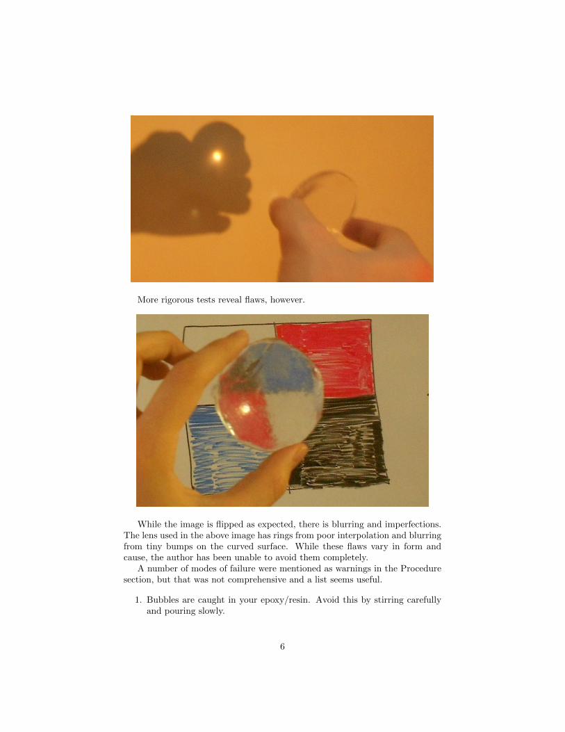
More rigorous tests reveal flaws, however.
While the image is flipped as expected, there is blurring and imperfections.The lens used in the above image has rings from poor interpolation and blurringfrom tiny bumps on the curved surface. While these flaws vary in form andcause, the author has been unable to avoid them completely.
A number of modes of failure were mentioned as warnings in the Proceduresection, but that was not comprehensive and a list seems useful.
1. Bubbles are caught in your epoxy/resin. Avoid this by stirring carefullyand pouring slowly.
6

2. Casting material dripping out of your mold as it sets causes ripples on thesurface. This is more of an issue when the liquid is very viscous.
3. Air flow or vibration causes ripples.
4. Premature removal of the lens from its mold results in damage to thesurface.
5. Droplets of mold release create tiny flaws in surfaces.
6. Setting lenses with ‘tacky’ surfaces on most other surfaces will damagethem.
7. Finger prints can easily form if a soft lens is not handled from the edge.
Additionally, if one is using a plastic wrap coated mold, there is the addi-tional concern of plastic wrap popping up during setting. Depending on howlong the lens has had to set, it may bend and wrinkle or pop out of the mold –both are problematic.
4 Conclusion
While the lenses that have been produced with the outlined technique are incom-parable to commercial optics, and fall short of the quality needed for most visualapplications, they are of sufficient quality to be used for some low-precision lightdistribution applications like collimating light in a flashlight. Furthermore, thewide variety in modes of failure is reason to believe that much higher qualitycan be achieved, since each one, evidently, can be defeated individually. It issimply a matter of perfecting the technique.
The author intends to pursue this until he can 3D print a telescope...
7