Embed Size (px)
Citation preview
Prodigy and
Prodigy Plus
Cuber Technical
Training C0330, C0530, C0630
C0830, C1030
C0322, C0522
C1448, C1848, C2148 C0722
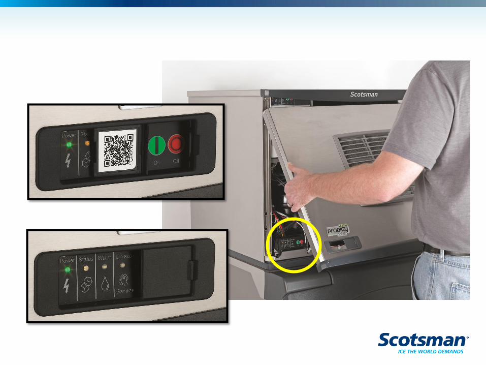
What’s New – Prodigy Plus
•Panels
– Air flow front to back
– Front pulls out at bottom
– Indicator lights and switch access at bottom front
•Controller
– Connects to lower light and switch panel
– New part number, new service controller will work on
any Prodigy cuber
– Cleaning process one button push
• No longer has to empty sump to add water
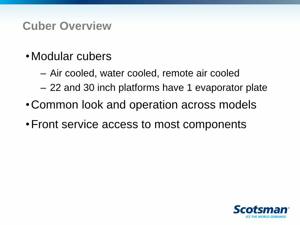
Cuber Overview
•Modular cubers
– Air cooled, water cooled, remote air cooled
– 22 and 30 inch platforms have 1 evaporator plate
•Common look and operation across models
•Front service access to most components
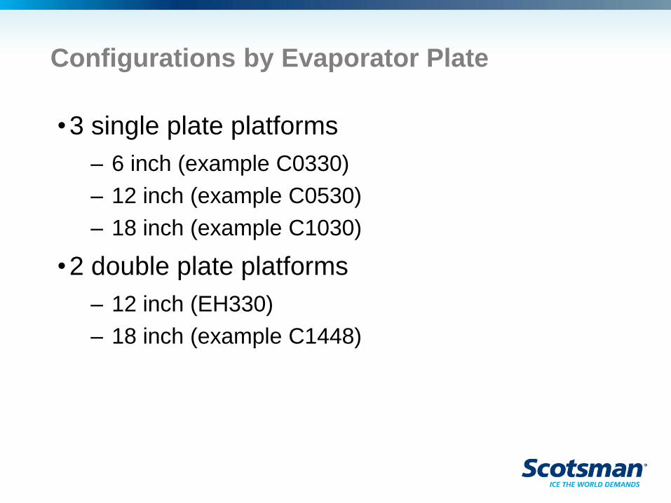
Configurations by Evaporator Plate
•3 single plate platforms
– 6 inch (example C0330)
– 12 inch (example C0530)
– 18 inch (example C1030)
•2 double plate platforms
– 12 inch (EH330)
– 18 inch (example C1448)

Installation
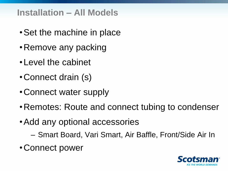
Installation – All Models
•Set the machine in place
•Remove any packing
•Level the cabinet
•Connect drain (s)
•Connect water supply
•Remotes: Route and connect tubing to condenser
•Add any optional accessories
– Smart Board, Vari Smart, Air Baffle, Front/Side Air In
•Connect power
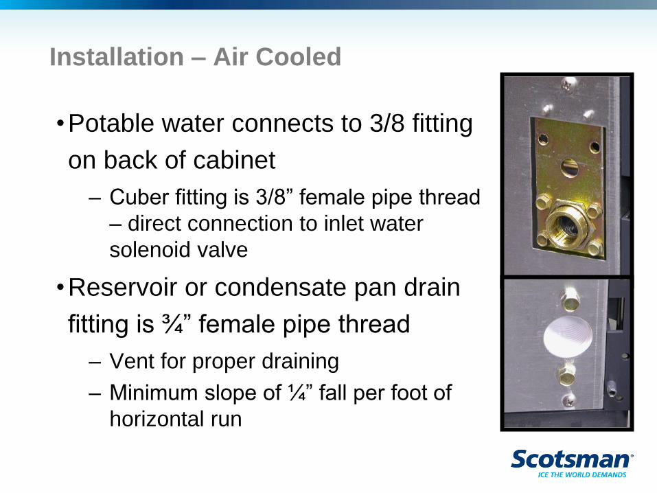
Installation – Air Cooled
•Potable water connects to 3/8 fitting
on back of cabinet
– Cuber fitting is 3/8” female pipe thread
– direct connection to inlet water
solenoid valve
•Reservoir or condensate pan drain
fitting is ¾” female pipe thread
– Vent for proper draining
– Minimum slope of ¼” fall per foot of
horizontal run
Air Flow
•A, B or C series
– Air flows in the left side and out the back
– 48 inch is in the left and front and out the back
•D series, Prodigy Plus
– Air flows in the front and out the back
– 48 inch is in the left and front and out the back
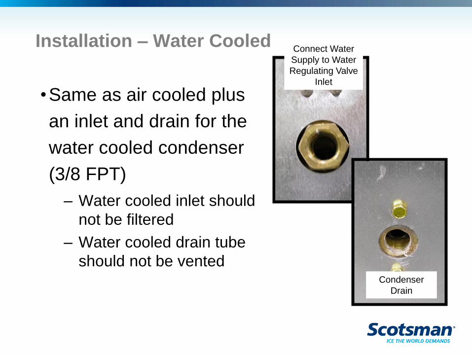
Installation – Water Cooled
•Same as air cooled plus
an inlet and drain for the
water cooled condenser
(3/8 FPT)
– Water cooled inlet should
not be filtered
– Water cooled drain tube
should not be vented
Connect Water
Supply to Water
Regulating Valve
Inlet
Condenser
Drain
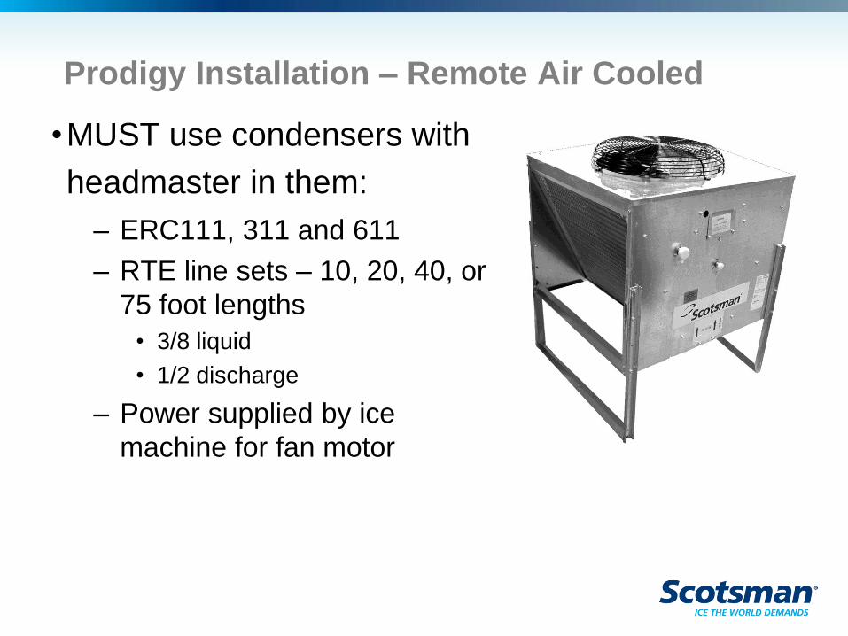
Prodigy Installation – Remote Air Cooled
•MUST use condensers with
headmaster in them:
– ERC111, 311 and 611
– RTE line sets – 10, 20, 40, or
75 foot lengths
• 3/8 liquid
• 1/2 discharge
– Power supplied by ice
machine for fan motor
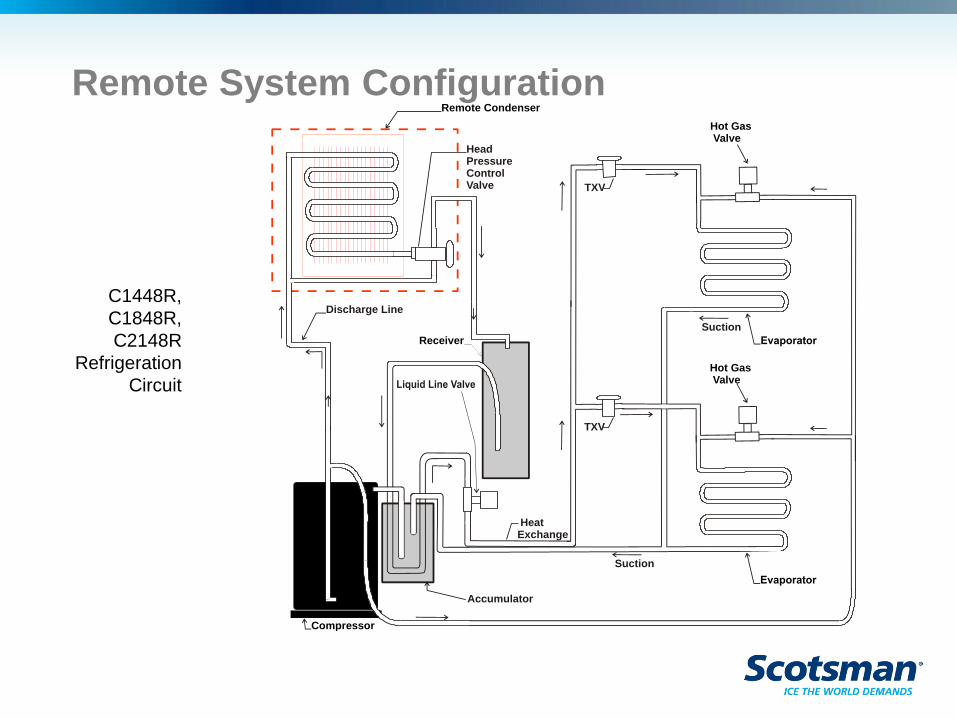
Remote System Configuration
C1448R,
C1848R,
C2148R
Refrigeration
Circuit
Receiver
Compressor
Remote Condenser
Hot Gas Valve
Hot Gas Valve
Discharge Line
Accumulator
Head PressureControl Valve
Heat Exchange
Suction
TXV
Suction
TXV
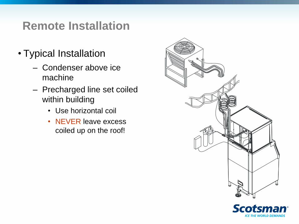
Remote Installation
• Typical Installation
– Condenser above ice
machine
– Precharged line set coiled
within building
• Use horizontal coil
• NEVER leave excess
coiled up on the roof!
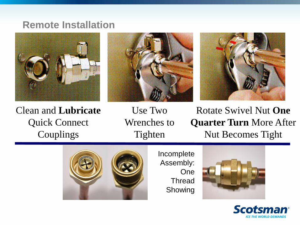
Clean and Lubricate
Quick Connect
Couplings
Use Two
Wrenches to
Tighten
Rotate Swivel Nut One
Quarter Turn More After
Nut Becomes Tight
Remote Installation
Incomplete
Assembly:
One
Thread
Showing
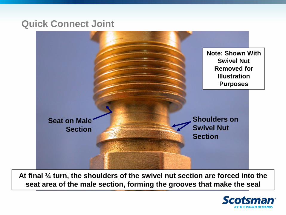
Quick Connect Joint
Shoulders on
Swivel Nut
Section
Seat on Male
Section
Note: Shown With
Swivel Nut
Removed for
Illustration
Purposes
At final ¼ turn, the shoulders of the swivel nut section are forced into the
seat area of the male section, forming the grooves that make the seal
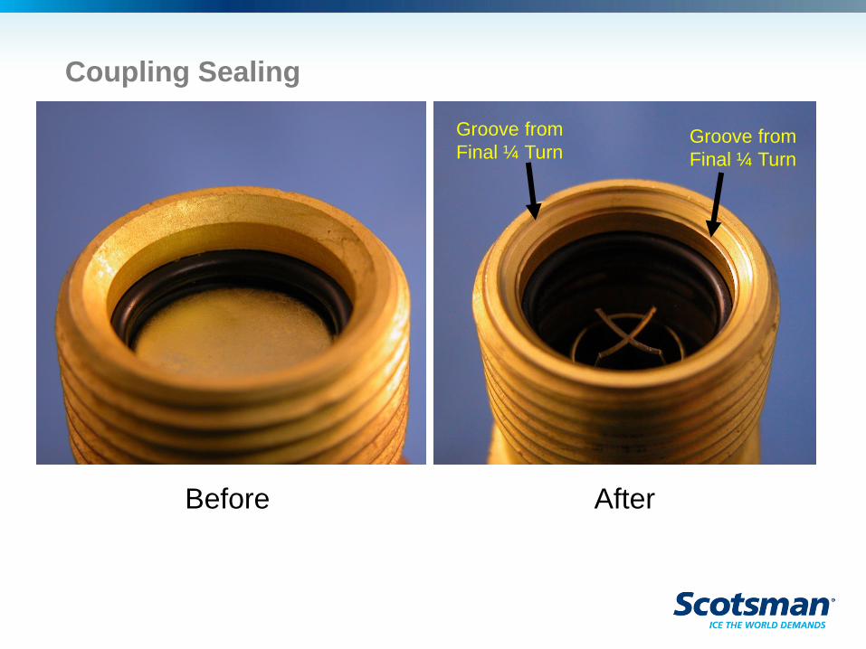
Coupling Sealing
Before After
Groove from
Final ¼ Turn Groove from
Final ¼ Turn

Cuber Operation
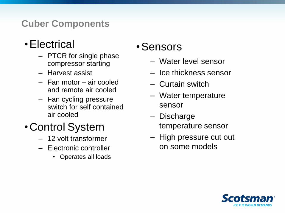
Cuber Components
•Electrical – PTCR for single phase
compressor starting
– Harvest assist
– Fan motor – air cooled and remote air cooled
– Fan cycling pressure switch for self contained air cooled
•Control System – 12 volt transformer
– Electronic controller
• Operates all loads
•Sensors
– Water level sensor
– Ice thickness sensor
– Curtain switch
– Water temperature
sensor
– Discharge
temperature sensor
– High pressure cut out
on some models
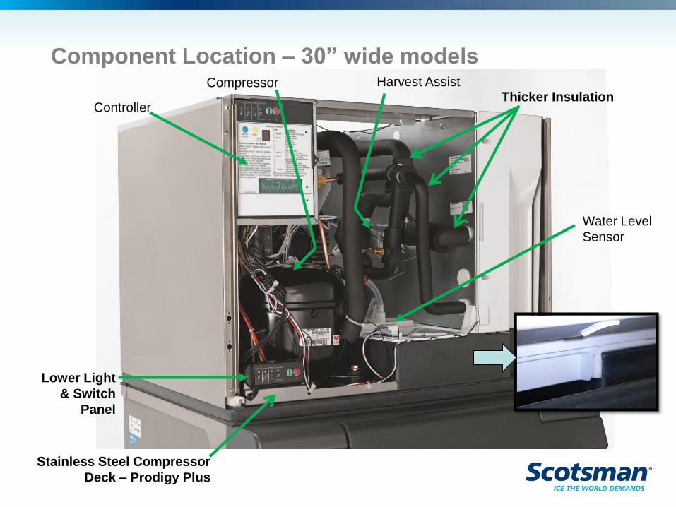
Component Location – 30” wide models
Controller
Harvest Assist
Lower Light
& Switch
Panel
Compressor
Water Level
Sensor
Stainless Steel Compressor
Deck – Prodigy Plus
Thicker Insulation
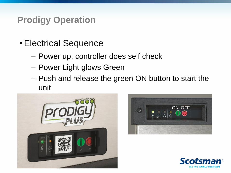
Prodigy Operation
•Electrical Sequence
– Power up, controller does self check
– Power Light glows Green
– Push and release the green ON button to start the
unit
ON OFF
Cuber Start Up – Air and Water Cooled
•Reservoir emptied and refilled
– Purge valve opens, water pump starts
– Hot gas and harvest assist solenoid activate
– Inlet water valve opens, water fills the reservoir
– Purge valve closes, pump shuts off
•When the reservoir is full, the water stops and
the compressor and pump start
– Fan motor will start when discharge pressure
increases to cut in point of fan cycle switch
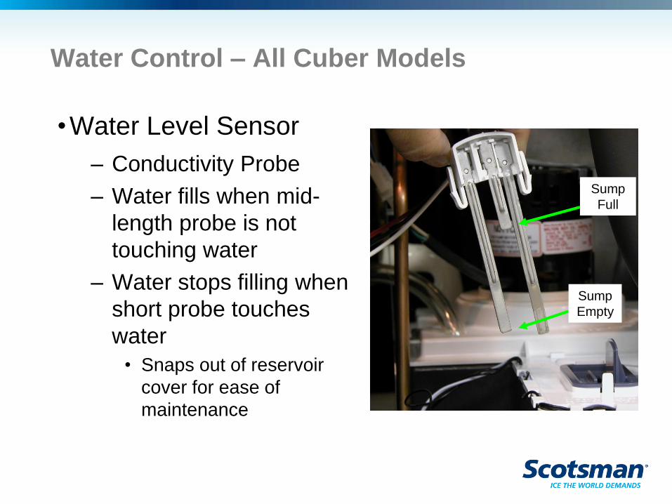
Water Control – All Cuber Models
•Water Level Sensor
– Conductivity Probe
– Water fills when mid-
length probe is not
touching water
– Water stops filling when
short probe touches
water
• Snaps out of reservoir
cover for ease of
maintenance
Sump
Full
Sump
Empty
Freeze Cycle
•Hot gas valve closes and harvest assist pin
retracts after 5 seconds of freeze.
– Allows compressor to start with minimal discharge
pressure
•Freeze continues until reservoir temp falls to
preset point, then pump stops for 30 seconds.
– The dry freeze is an anti-slush process
Operation - Freeze
•Compressor: ON
•Water pump: ON
•Fan motor: ON
•Purge valve: OFF
• Inlet water solenoid: OFF
•Harvest assist: OFF (after 5 seconds)
•Hot Gas valve: OFF (after 5 seconds)
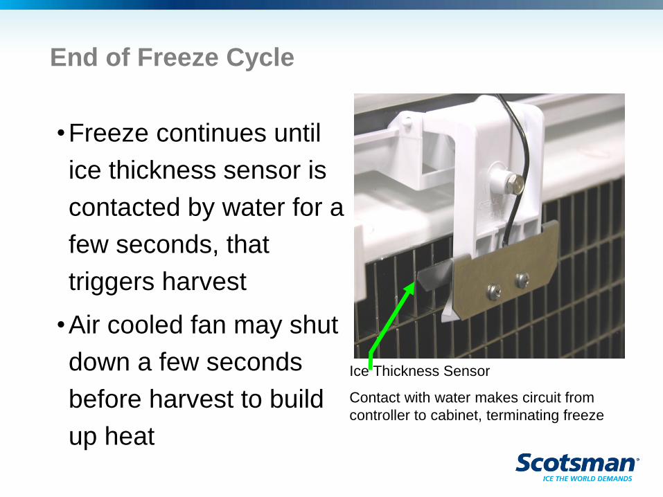
End of Freeze Cycle
•Freeze continues until
ice thickness sensor is
contacted by water for a
few seconds, that
triggers harvest
•Air cooled fan may shut
down a few seconds
before harvest to build
up heat
Ice Thickness Sensor
Contact with water makes circuit from
controller to cabinet, terminating freeze
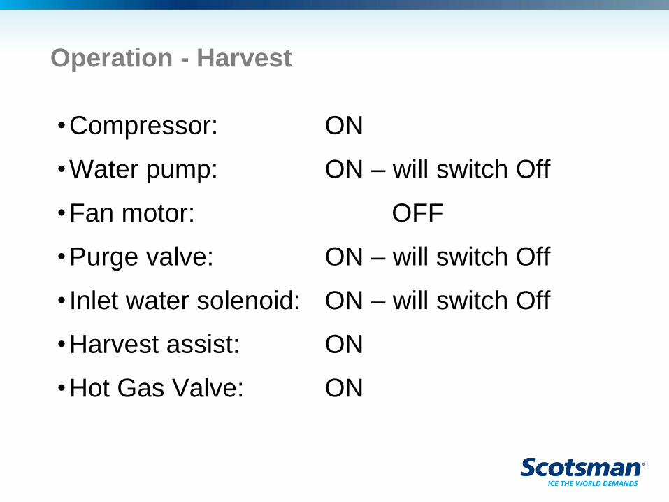
Operation - Harvest
•Compressor: ON
•Water pump: ON – will switch Off
•Fan motor: OFF
•Purge valve: ON – will switch Off
• Inlet water solenoid: ON – will switch Off
•Harvest assist: ON
•Hot Gas Valve: ON
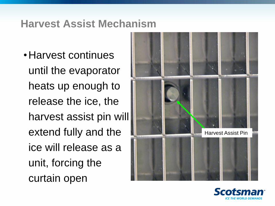
Harvest Assist Mechanism
•Harvest continues
until the evaporator
heats up enough to
release the ice, the
harvest assist pin will
extend fully and the
ice will release as a
unit, forcing the
curtain open
Harvest Assist Pin
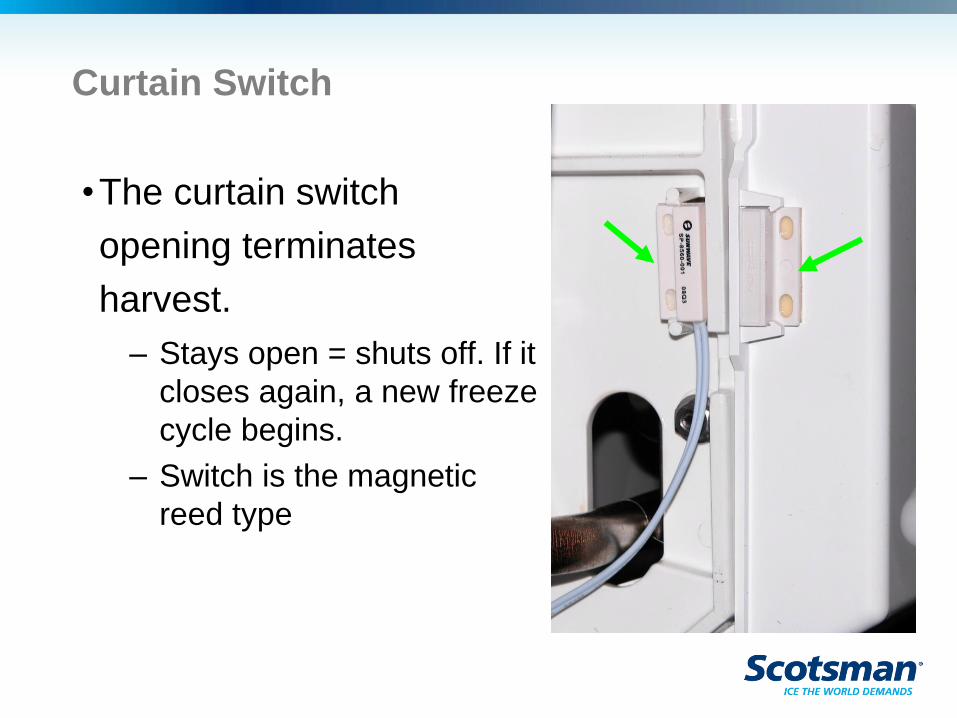
Curtain Switch
•The curtain switch
opening terminates
harvest.
– Stays open = shuts off. If it
closes again, a new freeze
cycle begins.
– Switch is the magnetic
reed type
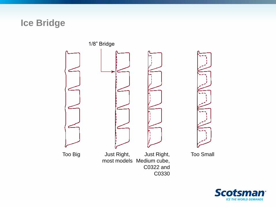
Ice Bridge
1/8” Bridge
Too Small Too Big Just Right,
most models
Just Right,
Medium cube,
C0322 and
C0330
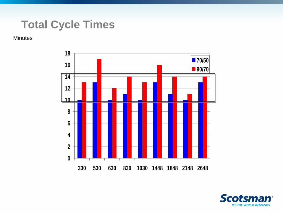
Total Cycle Times
0
2
4
6
8
10
12
14
16
18
330 530 630 830 1030 1448 1848 2148 2648
70/50
90/70
Minutes
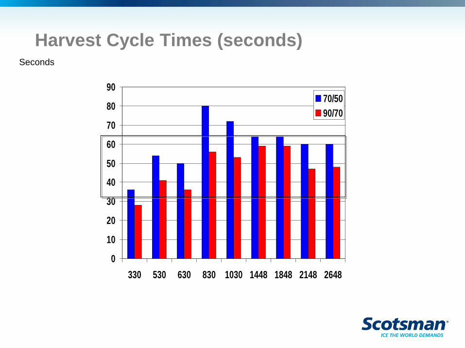
Harvest Cycle Times (seconds)
0
10
20
30
40
50
60
70
80
90
330 530 630 830 1030 1448 1848 2148 2648
70/50
90/70
Seconds
Bin Full
•The curtain switch is the bin full detector
– A full bin keeps the curtain from closing
– When open during harvest for more than 30 seconds
shuts the unit off
– 2 plate models must have both curtain switches open
to end harvest, and at least one to stay open for
more than 30 seconds to stop ice making.
•KVS / Vari Smart control can also shut the
machine off
– Based on ice level and setting of the control
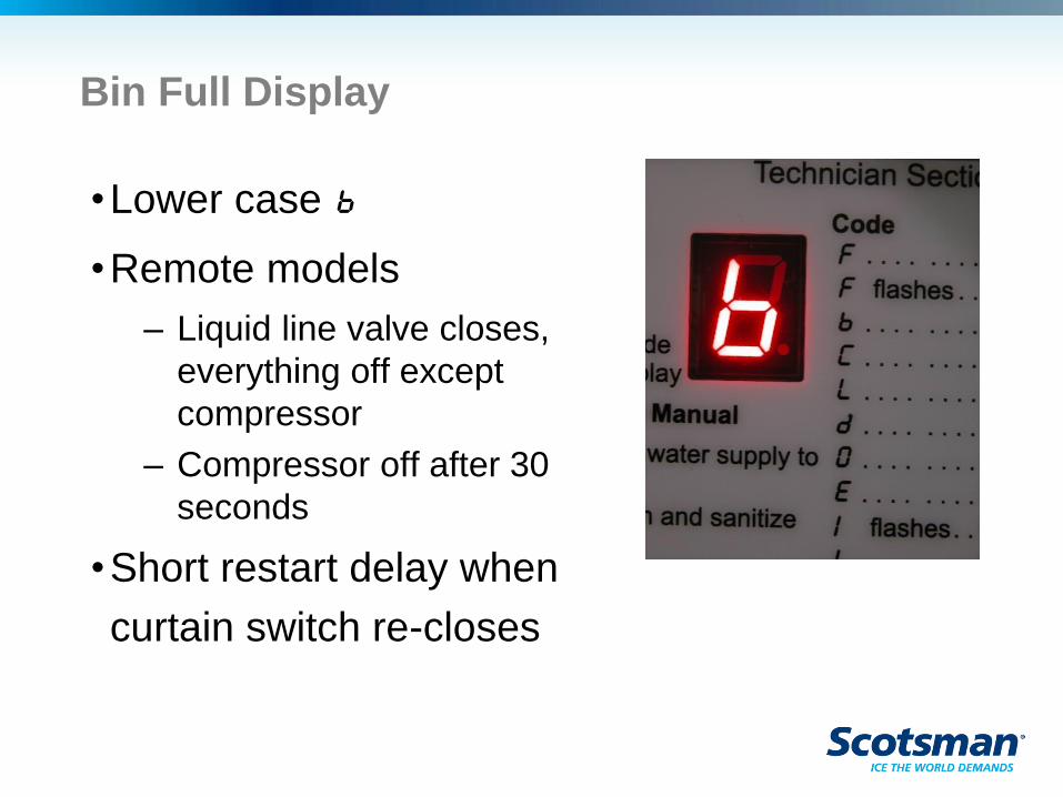
Bin Full Display
•Lower case b
•Remote models
– Liquid line valve closes,
everything off except
compressor
– Compressor off after 30
seconds
•Short restart delay when
curtain switch re-closes
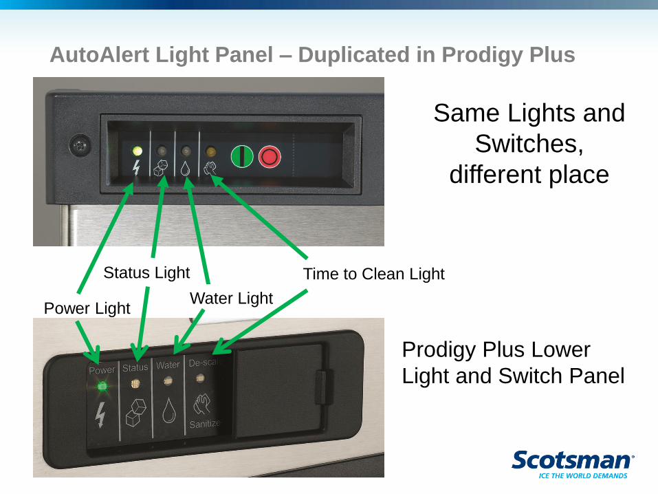
AutoAlert Light Panel – Duplicated in Prodigy Plus
Power Light
Status Light
Water Light
Time to Clean Light
Prodigy Plus Lower
Light and Switch Panel
Same Lights and
Switches,
different place
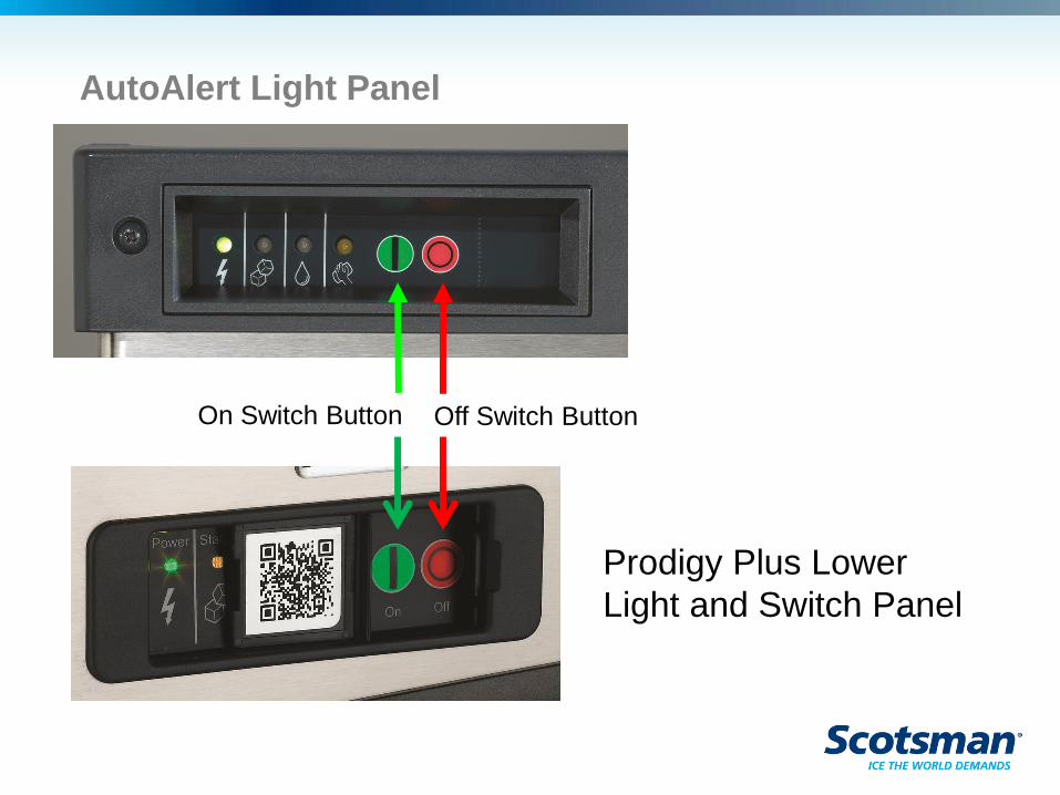
AutoAlert Light Panel
On Switch Button Off Switch Button
Prodigy Plus Lower
Light and Switch Panel
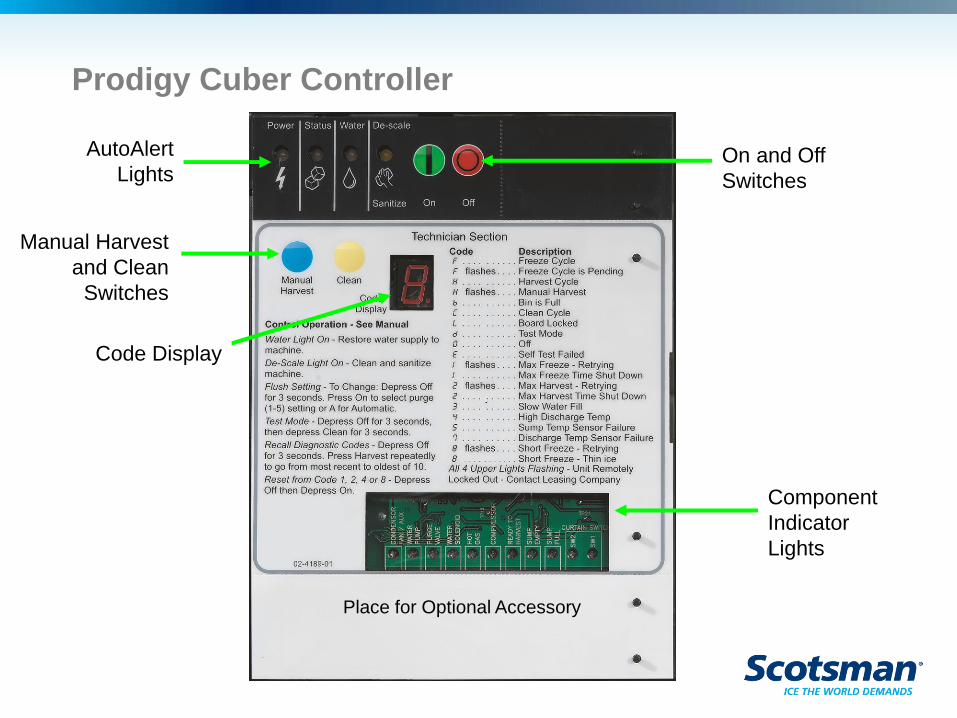
Prodigy Cuber Controller
AutoAlert
Lights
Manual Harvest
and Clean
Switches
Code Display
On and Off
Switches
Component
Indicator
Lights
Place for Optional Accessory
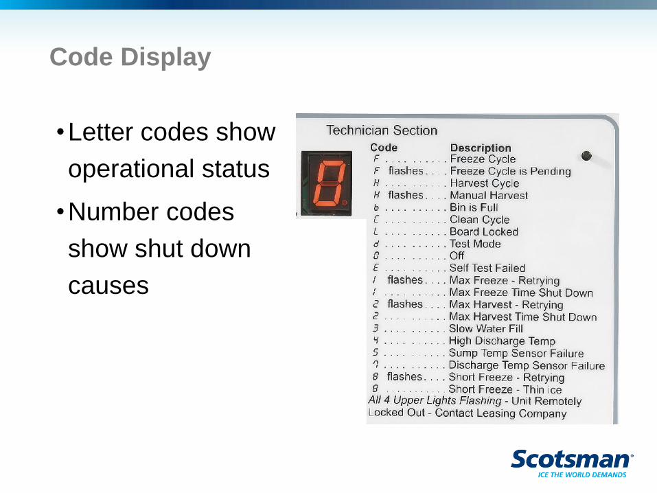
Code Display
•Letter codes show
operational status
•Number codes
show shut down
causes
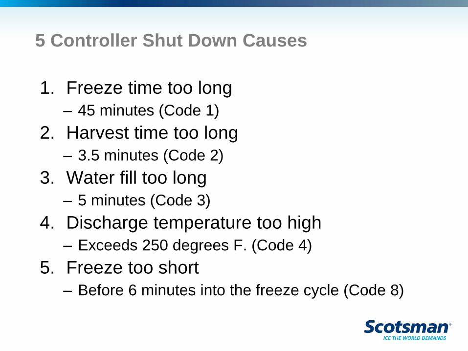
5 Controller Shut Down Causes
1. Freeze time too long
– 45 minutes (Code 1)
2. Harvest time too long
– 3.5 minutes (Code 2)
3. Water fill too long
– 5 minutes (Code 3)
4. Discharge temperature too high
– Exceeds 250 degrees F. (Code 4)
5. Freeze too short
– Before 6 minutes into the freeze cycle (Code 8)
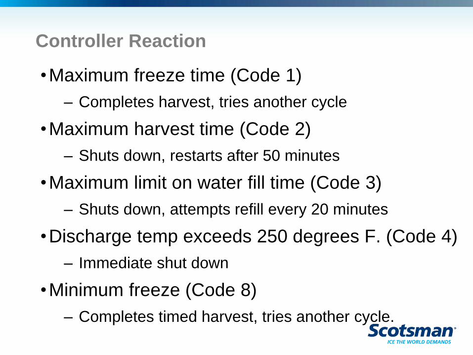
Controller Reaction
•Maximum freeze time (Code 1)
– Completes harvest, tries another cycle
•Maximum harvest time (Code 2)
– Shuts down, restarts after 50 minutes
•Maximum limit on water fill time (Code 3)
– Shuts down, attempts refill every 20 minutes
•Discharge temp exceeds 250 degrees F. (Code 4)
– Immediate shut down
•Minimum freeze (Code 8)
– Completes timed harvest, tries another cycle.
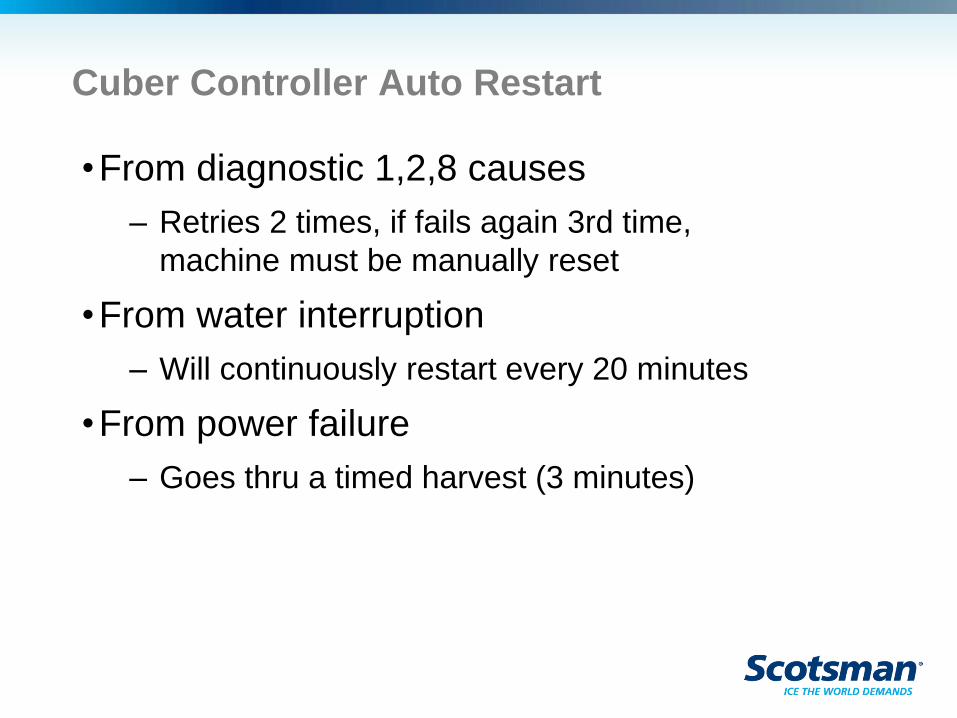
Cuber Controller Auto Restart
•From diagnostic 1,2,8 causes
– Retries 2 times, if fails again 3rd time,
machine must be manually reset
•From water interruption
– Will continuously restart every 20 minutes
•From power failure
– Goes thru a timed harvest (3 minutes)
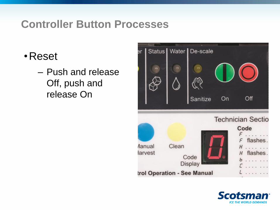
Controller Button Processes
•Reset
– Push and release
Off, push and
release On
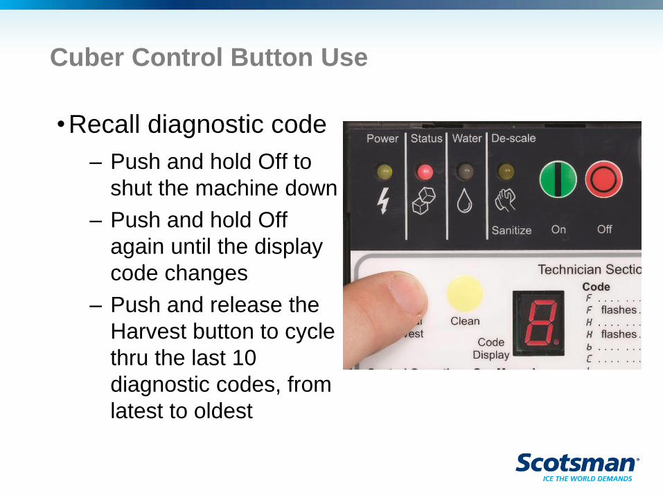
Cuber Control Button Use
•Recall diagnostic code
– Push and hold Off to
shut the machine down
– Push and hold Off
again until the display
code changes
– Push and release the
Harvest button to cycle
thru the last 10
diagnostic codes, from
latest to oldest
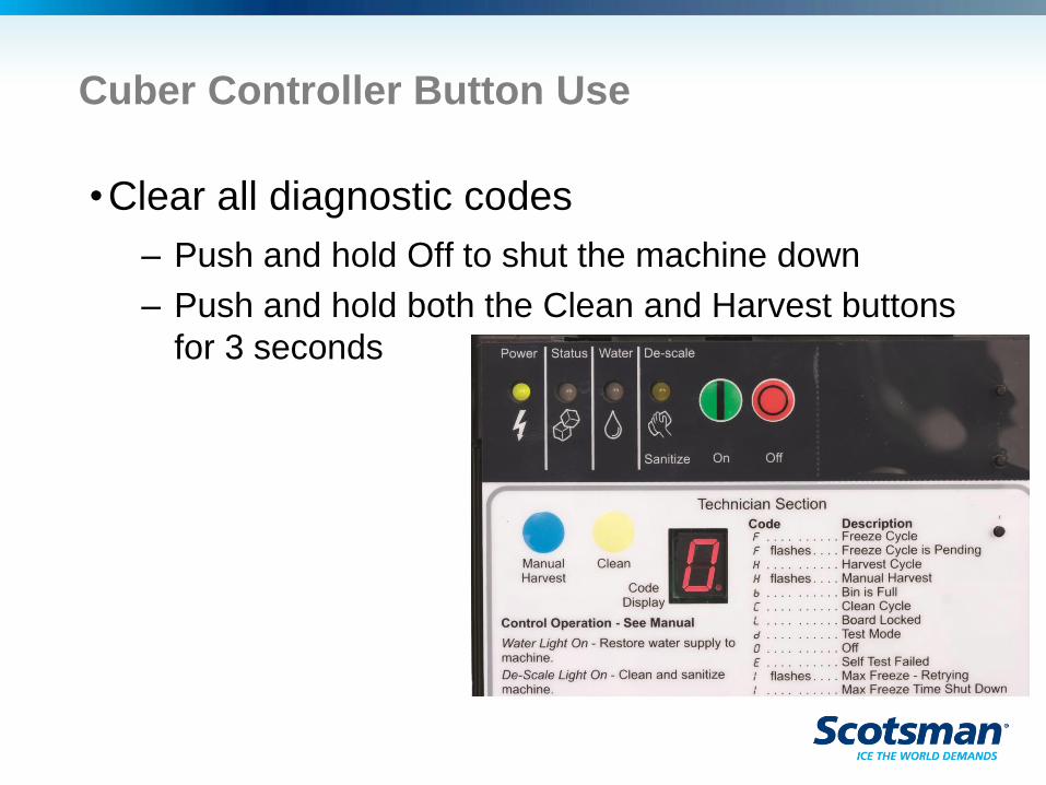
Cuber Controller Button Use
•Clear all diagnostic codes
– Push and hold Off to shut the machine down
– Push and hold both the Clean and Harvest buttons
for 3 seconds
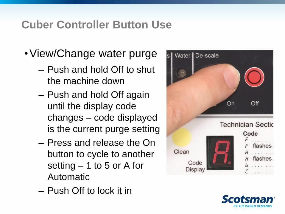
Cuber Controller Button Use
•View/Change water purge
– Push and hold Off to shut
the machine down
– Push and hold Off again
until the display code
changes – code displayed
is the current purge setting
– Press and release the On
button to cycle to another
setting – 1 to 5 or A for
Automatic
– Push Off to lock it in
WaterSense Automatic Purge
•Checks conductivity of reservoir water at start up
– Must be not less than 10 microSiemens/cm
•Adjusts purge water amount based on water’s TDS
– Display shows an A if set to Automatic (factory default)
•Purge can also be manually set
– 1 is minimum
– 5 is maximum
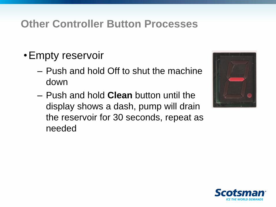
Other Controller Button Processes
•Empty reservoir
– Push and hold Off to shut the machine
down
– Push and hold Clean button until the
display shows a dash, pump will drain
the reservoir for 30 seconds, repeat as
needed

Cuber Diagnostics
Most Common Service Call
•No Ice
– Why?
– Dirty ice machine – sensors and water
distributor fouled, purge ineffective
– Lack of water – filter plugged
– Lack of air – filter plugged, condenser dirty
Second Most Common Service Call
•Poor performance – not keeping up
– Why?
– Machine is too hot, cycle time long
• Dirty
• Installed too close to other equipment
• In a corner, in a closet
• Not enough HVAC
• Bad installation
Cuber Cycle Time
•Freeze plus harvest time equals total cycle
•Example: C1030 air cooled at 70/50 = 9-10
minutes cycle time.
•Hot environment, air, water or both, adds heat
load and makes the machine have longer cycles
•Sometimes it isn’t broken. Measure cycle time, if
normal and the bridge thickness is also correct,
the machine is making all it can.
Diagnostic Process
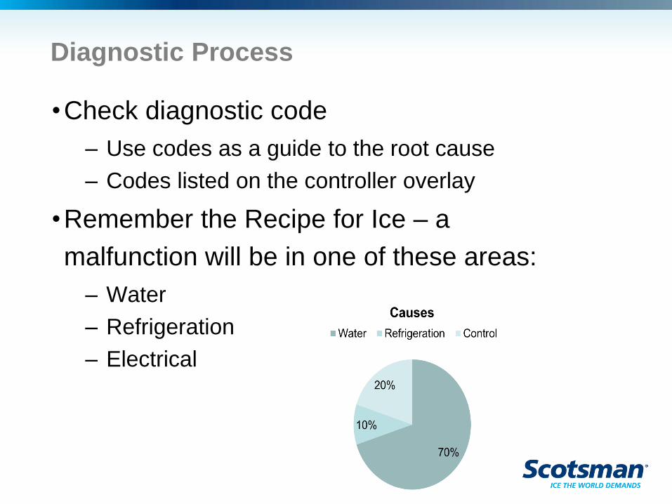
•Check diagnostic code
– Use codes as a guide to the root cause
– Codes listed on the controller overlay
•Remember the Recipe for Ice – a
malfunction will be in one of these areas:
– Water
– Refrigeration
– Electrical
Diagnostics
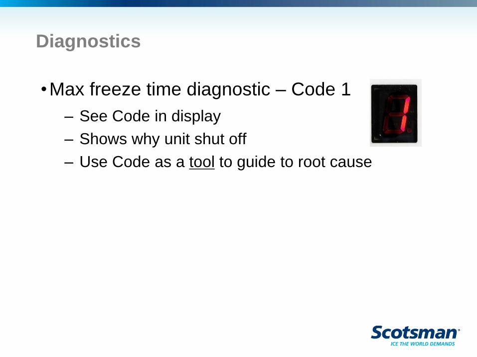
•Max freeze time diagnostic – Code 1
– See Code in display
– Shows why unit shut off
– Use Code as a tool to guide to root cause
Diagnostic Aids
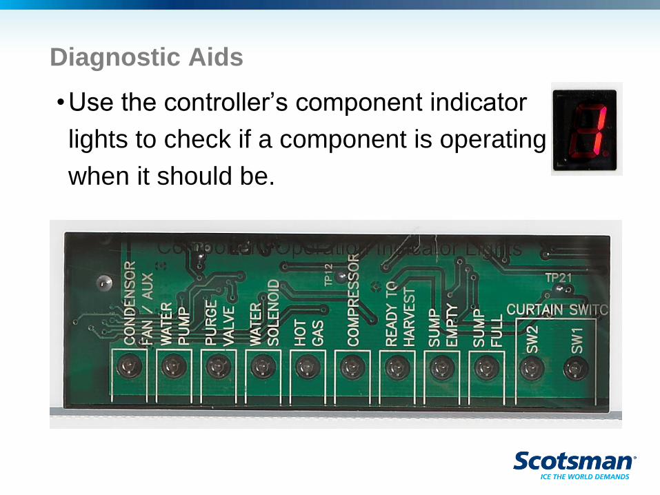
•Use the controller’s component indicator
lights to check if a component is operating
when it should be.
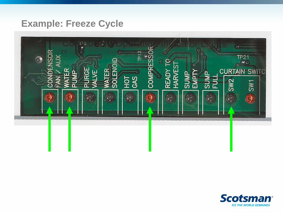
Example: Freeze Cycle
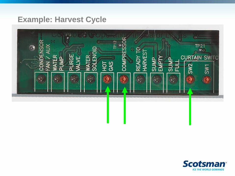
Example: Harvest Cycle
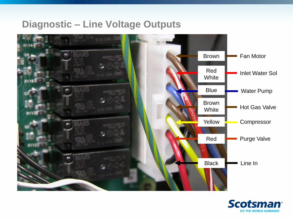
Diagnostic – Line Voltage Outputs
Fan Motor
Inlet Water Sol
Line In
Purge Valve
Compressor
Hot Gas Valve
Water Pump
Brown
Red
White
Blue
Brown
White
Yellow
Red
Black
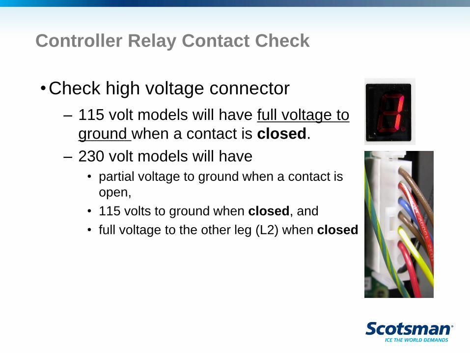
Controller Relay Contact Check
•Check high voltage connector
– 115 volt models will have full voltage to
ground when a contact is closed.
– 230 volt models will have
• partial voltage to ground when a contact is
open,
• 115 volts to ground when closed, and
• full voltage to the other leg (L2) when closed
Diagnostics
•Max freeze time diagnostic – Code 1
– Limit is 45 minutes
– Typical cycle is much shorter
• 15 to 20 minutes
– Long freeze cycle causes:
• Lack of water
• Lack of refrigeration effect
• Not sensing ice formation
Diagnostics – Code 1
•Lack of water flow potential causes:
– False Sump Full signal from Water Level
Sensor – dirt buildup
• Water will not be added if Sensor is shorted and
signaling Sump Full
– Water pump failure – potential scale caused
– Leaking Purge Valve – potential scale
caused
Diagnostics Code 1
•Lack of refrigeration may be caused by:
– Dirty air filters
– Fan motor or fan pressure control failure
– Water supply to water cooled condenser failure
– Low charge
– TXV superheat not correct
– Compressor contactor failure
– Compressor overheated or off
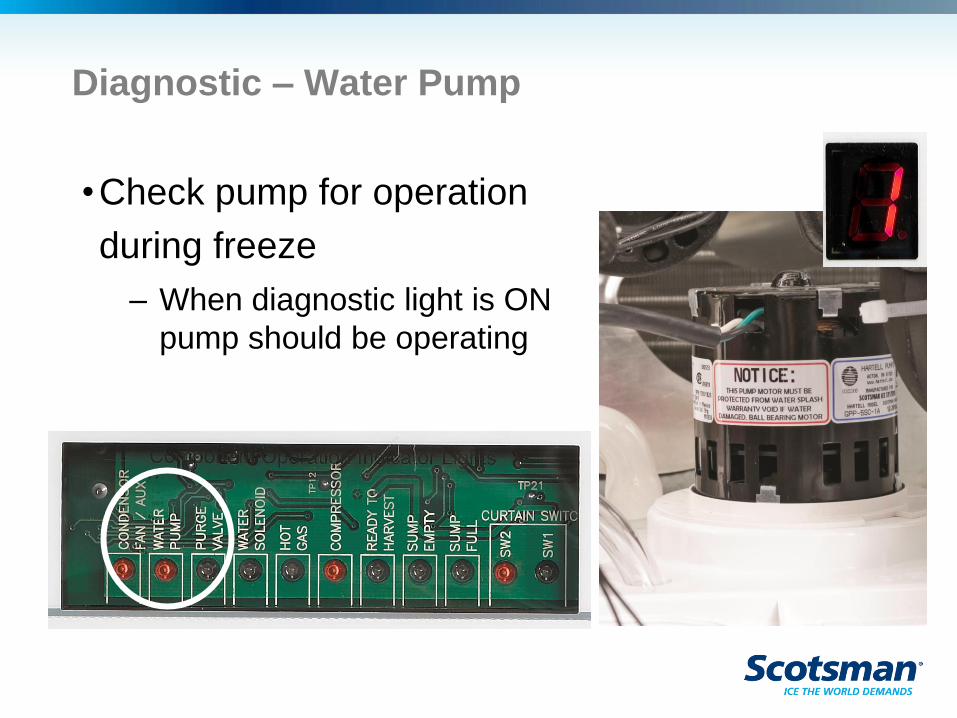
Diagnostic – Water Pump
•Check pump for operation
during freeze
– When diagnostic light is ON
pump should be operating
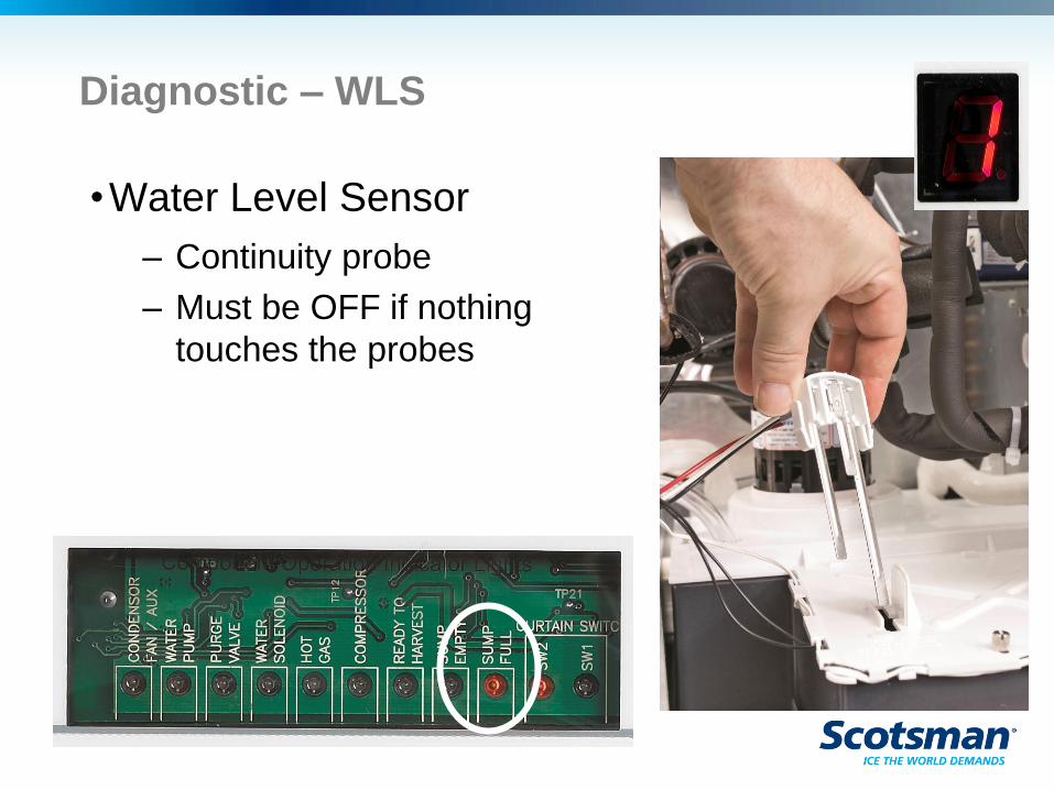
Diagnostic – WLS
•Water Level Sensor
– Continuity probe
– Must be OFF if nothing
touches the probes
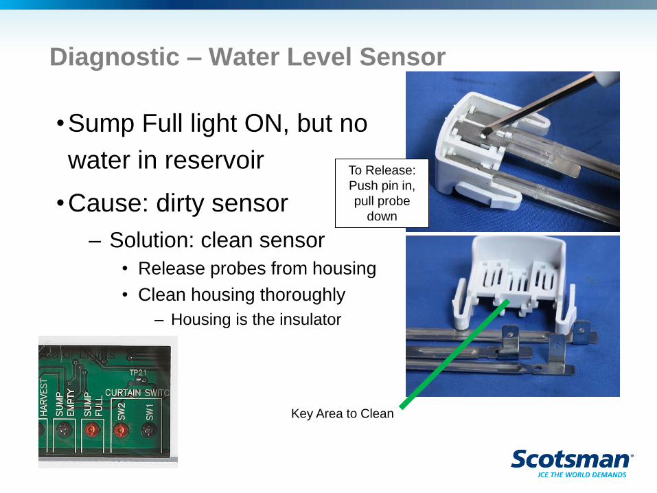
Diagnostic – Water Level Sensor
•Sump Full light ON, but no
water in reservoir
•Cause: dirty sensor
– Solution: clean sensor
• Release probes from housing
• Clean housing thoroughly
– Housing is the insulator
Key Area to Clean
To Release:
Push pin in,
pull probe
down
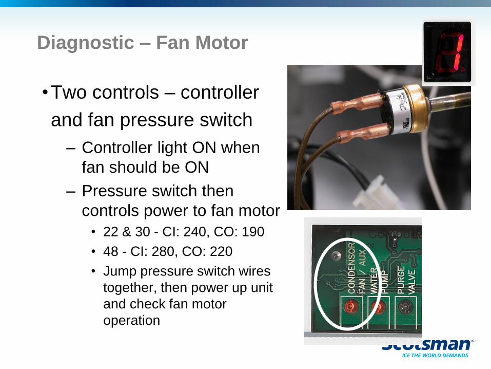
Diagnostic – Fan Motor
•Two controls – controller
and fan pressure switch
– Controller light ON when
fan should be ON
– Pressure switch then
controls power to fan motor
• 22 & 30 - CI: 240, CO: 190
• 48 - CI: 280, CO: 220
• Jump pressure switch wires
together, then power up unit
and check fan motor
operation
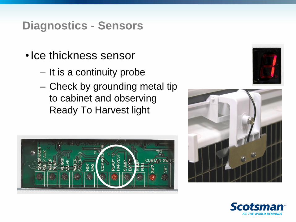
Diagnostics - Sensors
• Ice thickness sensor
– It is a continuity probe
– Check by grounding metal tip
to cabinet and observing
Ready To Harvest light
Diagnostics
•Max harvest time – Code 2
– Limit is 3 ½ minutes
– Normal time is between one and two
minutes
– Long harvest cycle possibly caused by:
• No ice due to no water after max freeze
• Harvest assist not functioning correctly
– Not extending or retracting
• Hot gas valve not opening
• Curtain switch not sensing when curtain opens
• Poor or No ice formation
• Low refrigerant charge
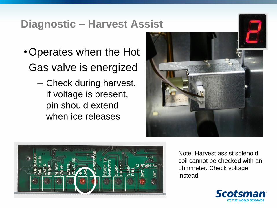
Diagnostic – Harvest Assist
•Operates when the Hot
Gas valve is energized
– Check during harvest,
if voltage is present,
pin should extend
when ice releases
Note: Harvest assist solenoid
coil cannot be checked with an
ohmmeter. Check voltage
instead.
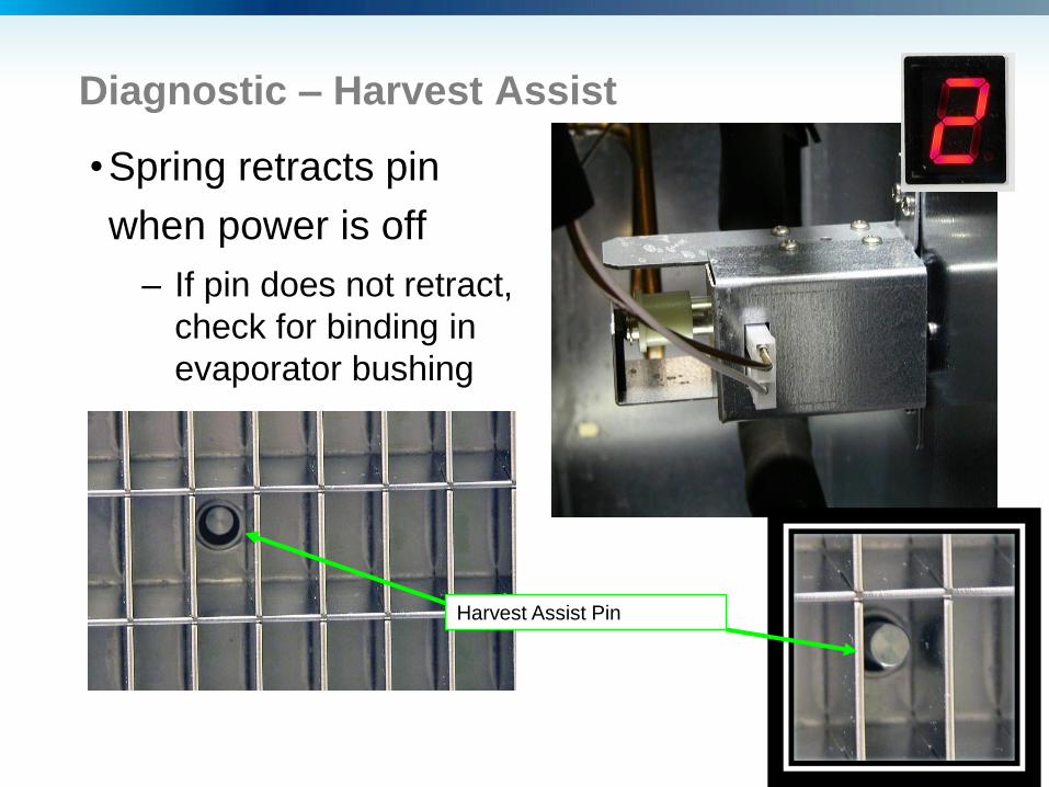
Diagnostic – Harvest Assist
•Spring retracts pin
when power is off
– If pin does not retract,
check for binding in
evaporator bushing
Harvest Assist Pin
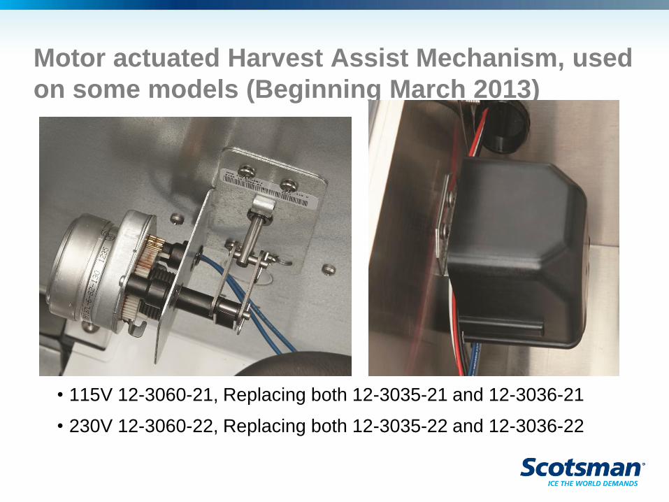
Motor actuated Harvest Assist Mechanism, used
on some models (Beginning March 2013)
• 115V 12-3060-21, Replacing both 12-3035-21 and 12-3036-21
• 230V 12-3060-22, Replacing both 12-3035-22 and 12-3036-22
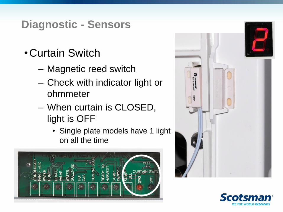
Diagnostic - Sensors
•Curtain Switch
– Magnetic reed switch
– Check with indicator light or
ohmmeter
– When curtain is CLOSED,
light is OFF
• Single plate models have 1 light
on all the time
Diagnostic – Hot Gas Valve
•Opens at start up and during harvest
•One per evaporator
•Line voltage coil
•Check power to coil when hot gas indicator light
is on
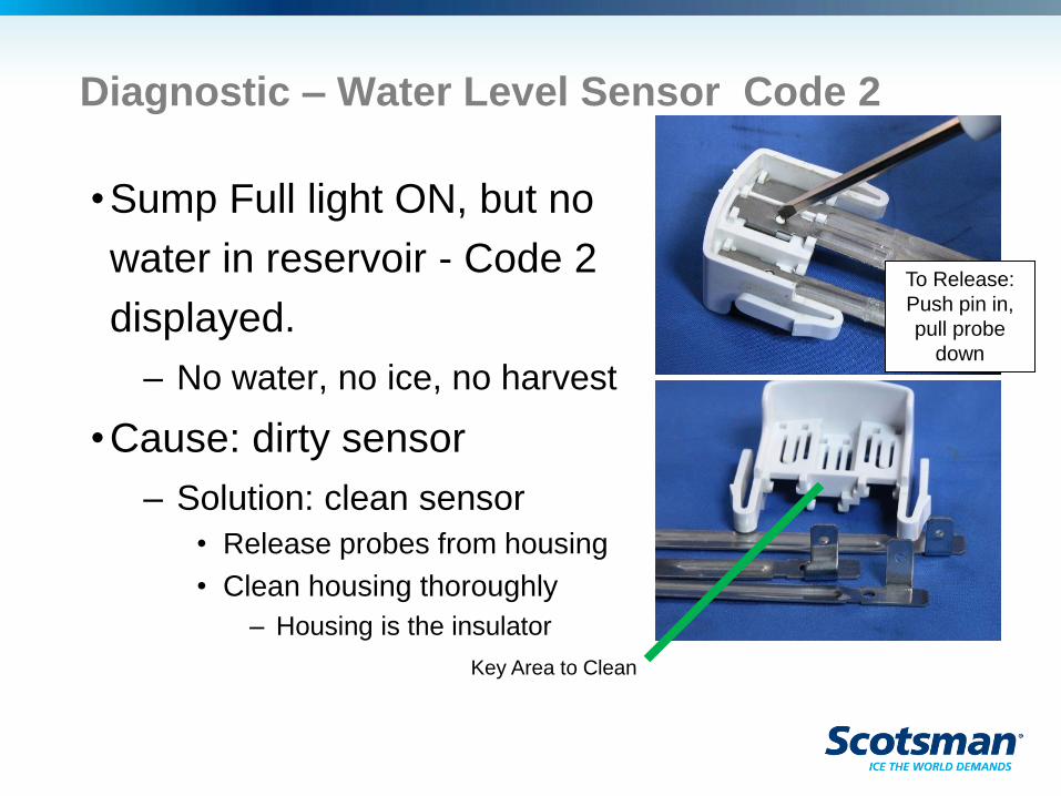
Diagnostic – Water Level Sensor Code 2
•Sump Full light ON, but no
water in reservoir - Code 2
displayed.
– No water, no ice, no harvest
•Cause: dirty sensor
– Solution: clean sensor
• Release probes from housing
• Clean housing thoroughly
– Housing is the insulator
Key Area to Clean
To Release:
Push pin in,
pull probe
down
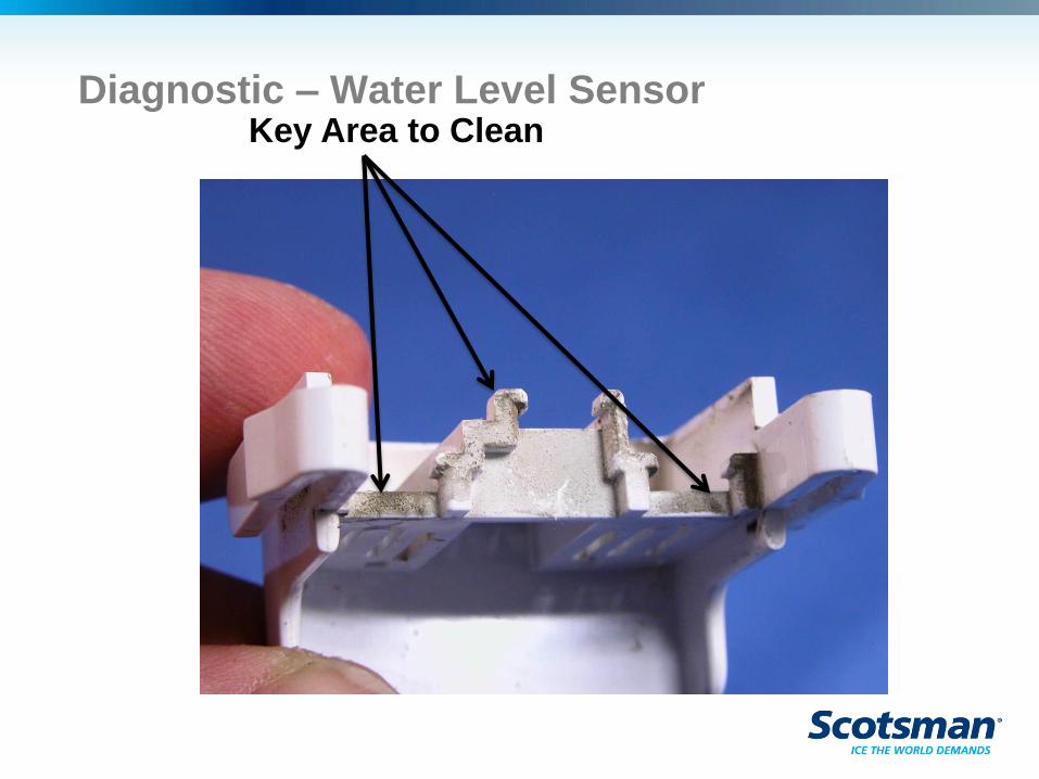
Key Area to Clean Diagnostic – Water Level Sensor
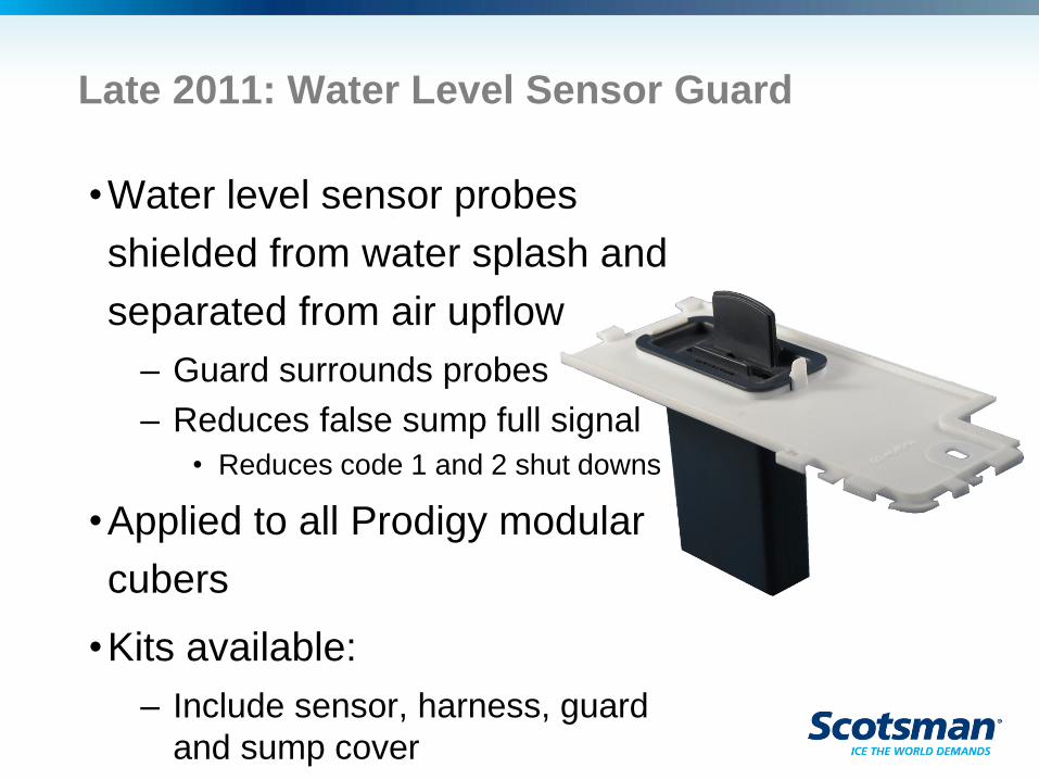
Late 2011: Water Level Sensor Guard
•Water level sensor probes
shielded from water splash and
separated from air upflow
– Guard surrounds probes
– Reduces false sump full signal
• Reduces code 1 and 2 shut downs
•Applied to all Prodigy modular
cubers
•Kits available:
– Include sensor, harness, guard
and sump cover
Diagnostics
•Slow or no water fill – Code 3
– Limit on fill time is 5 minutes
– Longer fill times possibly caused by:
• Water supply shut off
• Water filters plugged up
• Inlet water solenoid valve failure
• Controller not opening inlet water solenoid valve
• Purge valve leak
Purge valve
•Opens every cycle to drain some water;
dilutes mineral buildup
– Must drain freely – gravity drain
• External tubing can be a restriction – check for
venting and kinks
– Must open
– Must not leak by
• Reservoir will refill if Sump Empty detected
– Purge can be mis-adjusted by controller
setting
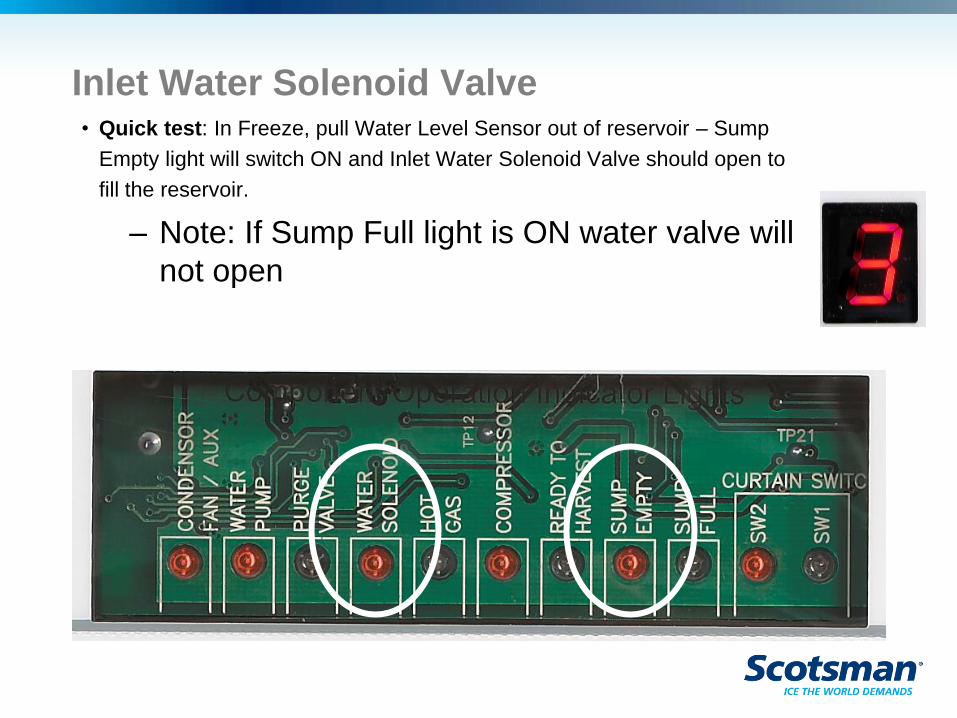
Inlet Water Solenoid Valve • Quick test: In Freeze, pull Water Level Sensor out of reservoir – Sump
Empty light will switch ON and Inlet Water Solenoid Valve should open to
fill the reservoir.
– Note: If Sump Full light is ON water valve will
not open
Diagnostics
•High discharge temperature – Code 4
– Immediate and complete shut off if
discharge temperature reaches 250oF.
– Possible causes of high discharge
temperature
• Fan motor failure
• Extreme high ambient
• Hot gas valve leak thru
• Too much superheat
Diagnostic - Sensors
•Display codes 5 or 7 indicate a sensor
failure
– Check by measuring resistance of
thermistor and comparing to the table at that
temperature
• Table of resistances in manual or handbook,
same as for CM3
•Operation can continue without
thermistor use, diagnostic code 5 will be
displayed when they are disconnected
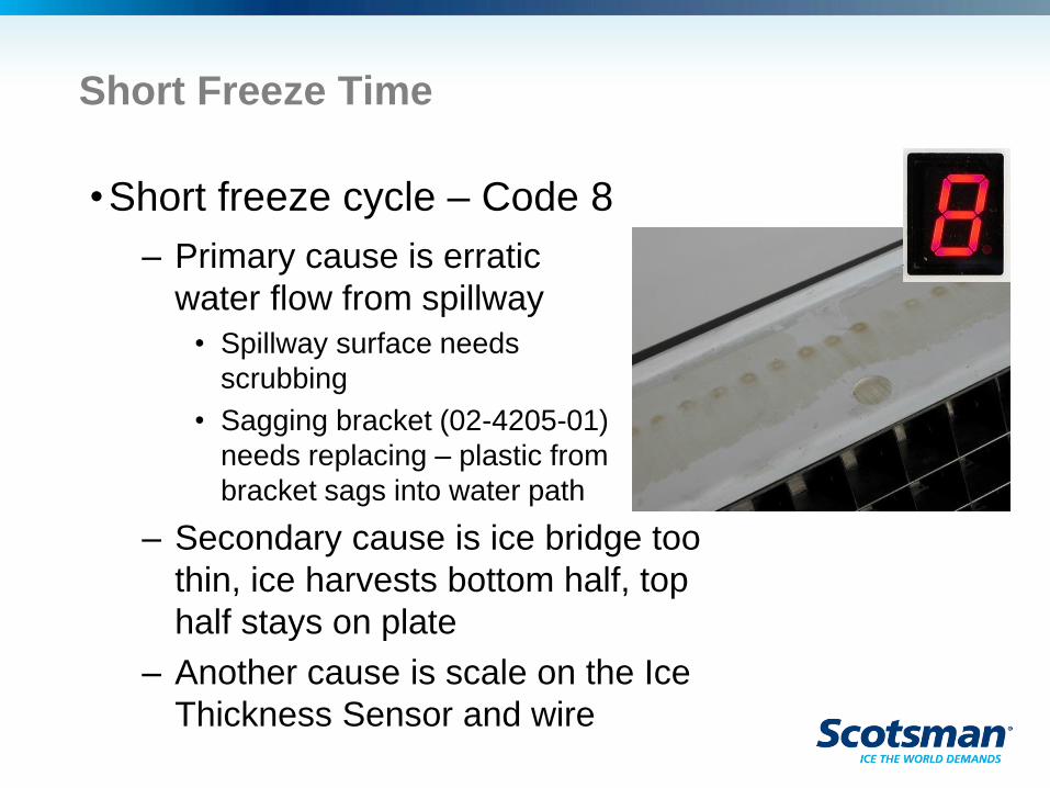
Short Freeze Time
•Short freeze cycle – Code 8
– Primary cause is erratic
water flow from spillway
• Spillway surface needs
scrubbing
• Sagging bracket (02-4205-01)
needs replacing – plastic from
bracket sags into water path
– Secondary cause is ice bridge too
thin, ice harvests bottom half, top
half stays on plate
– Another cause is scale on the Ice
Thickness Sensor and wire
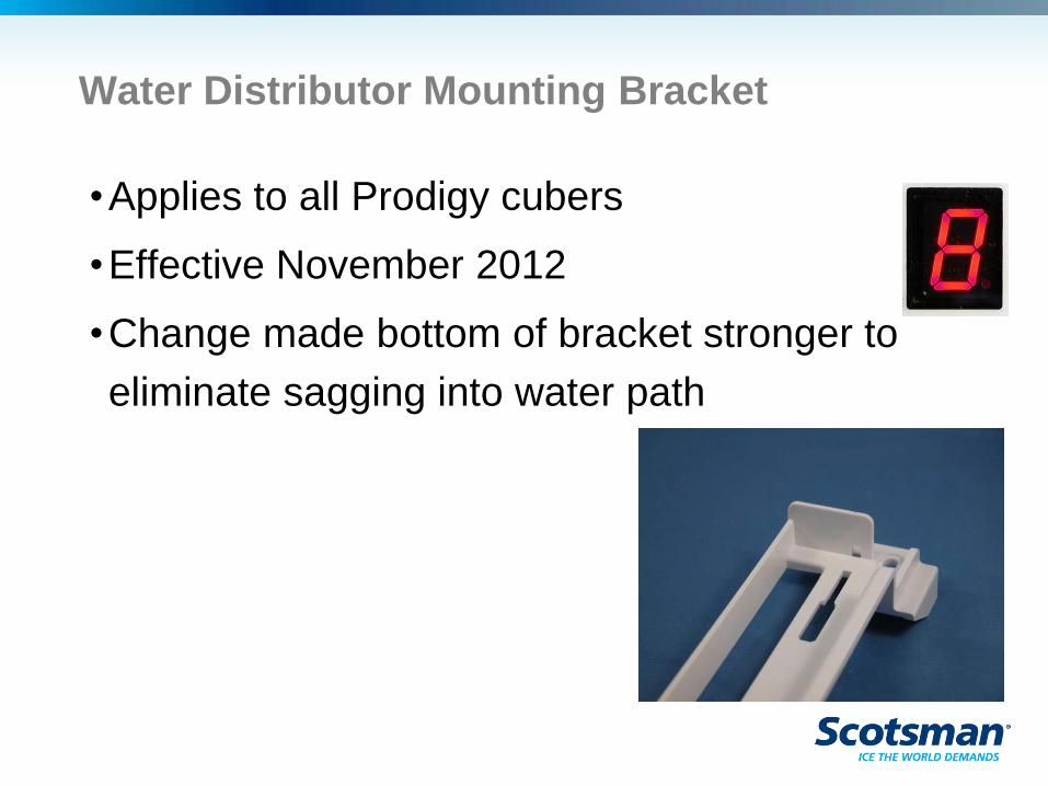
Water Distributor Mounting Bracket
•Applies to all Prodigy cubers
•Effective November 2012
•Change made bottom of bracket stronger to
eliminate sagging into water path
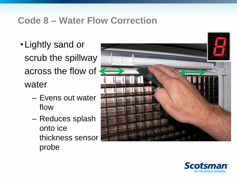
Code 8 – Water Flow Correction
•Lightly sand or
scrub the spillway
across the flow of
water
– Evens out water
flow
– Reduces splash
onto ice
thickness sensor
probe
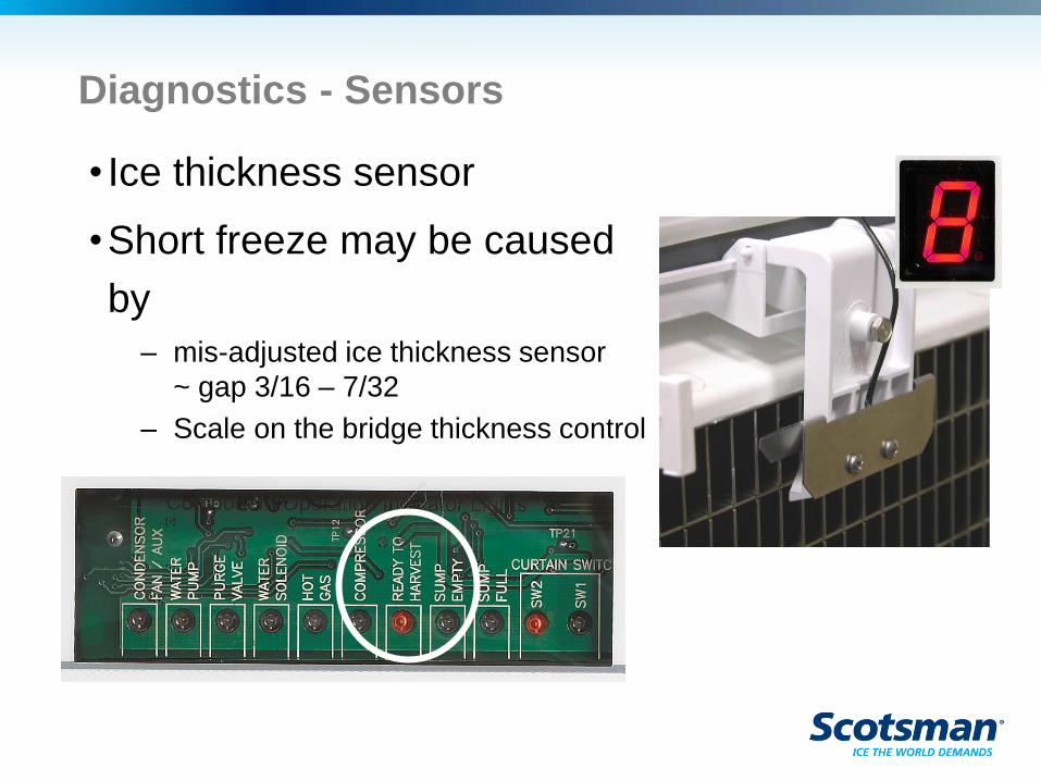
Diagnostics - Sensors
• Ice thickness sensor
•Short freeze may be caused
by
– mis-adjusted ice thickness sensor
~ gap 3/16 – 7/32
– Scale on the bridge thickness control
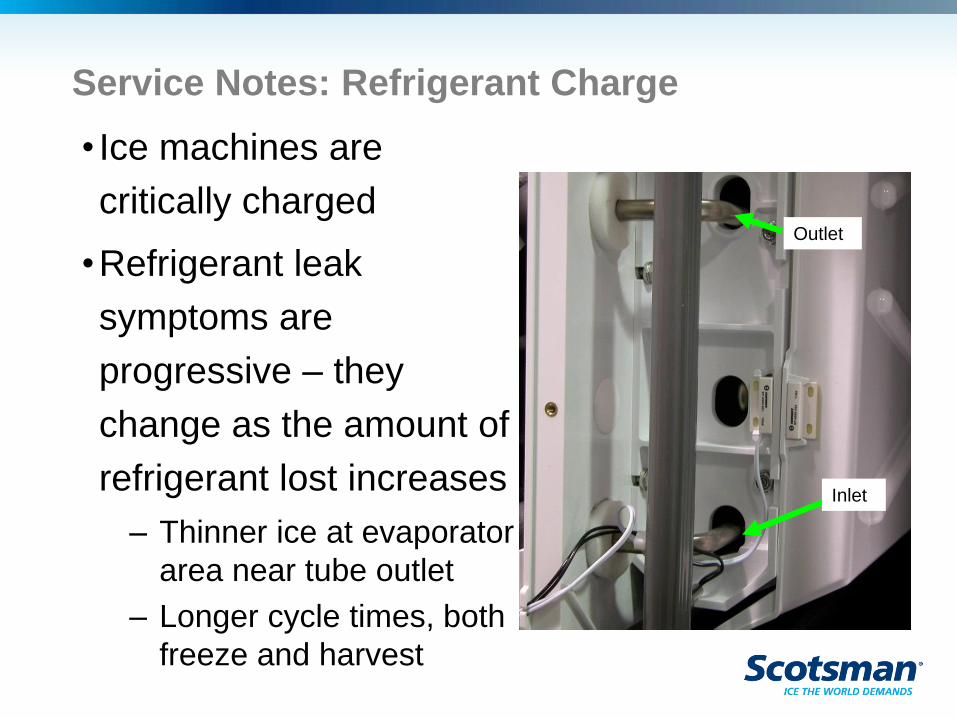
Service Notes: Refrigerant Charge
• Ice machines are
critically charged
•Refrigerant leak
symptoms are
progressive – they
change as the amount of
refrigerant lost increases
– Thinner ice at evaporator
area near tube outlet
– Longer cycle times, both
freeze and harvest
Outlet
Inlet
Diagnostics
•No ice complaint
– Machine is not making ice
– Bin is not full
– Status light is on
– Code b is displayed
– Possible causes:
• Curtain is open or off the unit
• Curtain switch is open
• Vari-smart is installed and set too low
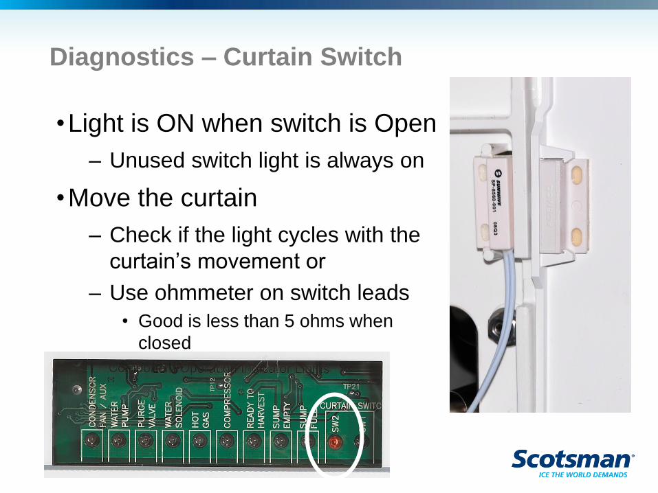
Diagnostics – Curtain Switch
•Light is ON when switch is Open
– Unused switch light is always on
•Move the curtain
– Check if the light cycles with the
curtain’s movement or
– Use ohmmeter on switch leads
• Good is less than 5 ohms when
closed
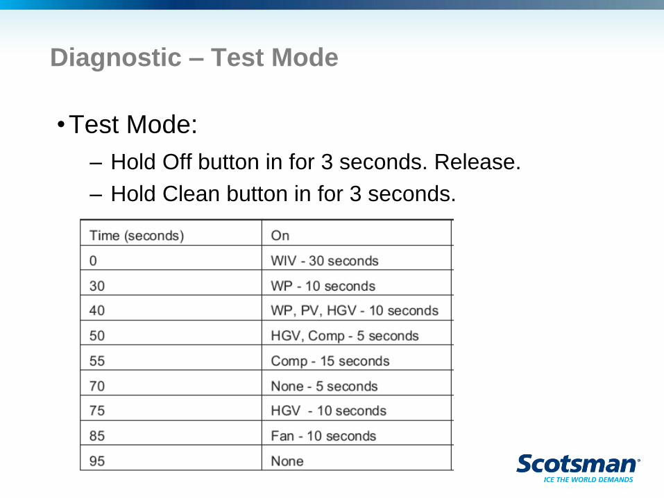
Diagnostic – Test Mode
•Test Mode:
– Hold Off button in for 3 seconds. Release.
– Hold Clean button in for 3 seconds.
Diagnostic - Power
•Continuous power supply is critical
•Remember: Auto restarts from power interruption
– Poor electrical connection can cause frequent to
continuous auto restarts
– If cord connected, try another outlet as a diagnostic
• Outlets wear out, can be defective and have poor
connections

Maintenance and
Cleaning
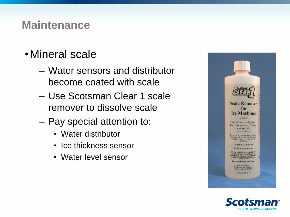
Maintenance
•Mineral scale
– Water sensors and distributor
become coated with scale
– Use Scotsman Clear 1 scale
remover to dissolve scale
– Pay special attention to:
• Water distributor
• Ice thickness sensor
• Water level sensor

Scale Removal and Sanitizing
•Begin by removing the ice from the bin or
dispenser.
•Sanitize the bin or dispenser at the end of the ice
machine cleaning process.
•You will need:
– Nickel safe ice machine cleaner
– Sanitizer
– Bucket, spray bottle, cloths, soft brush, gloves
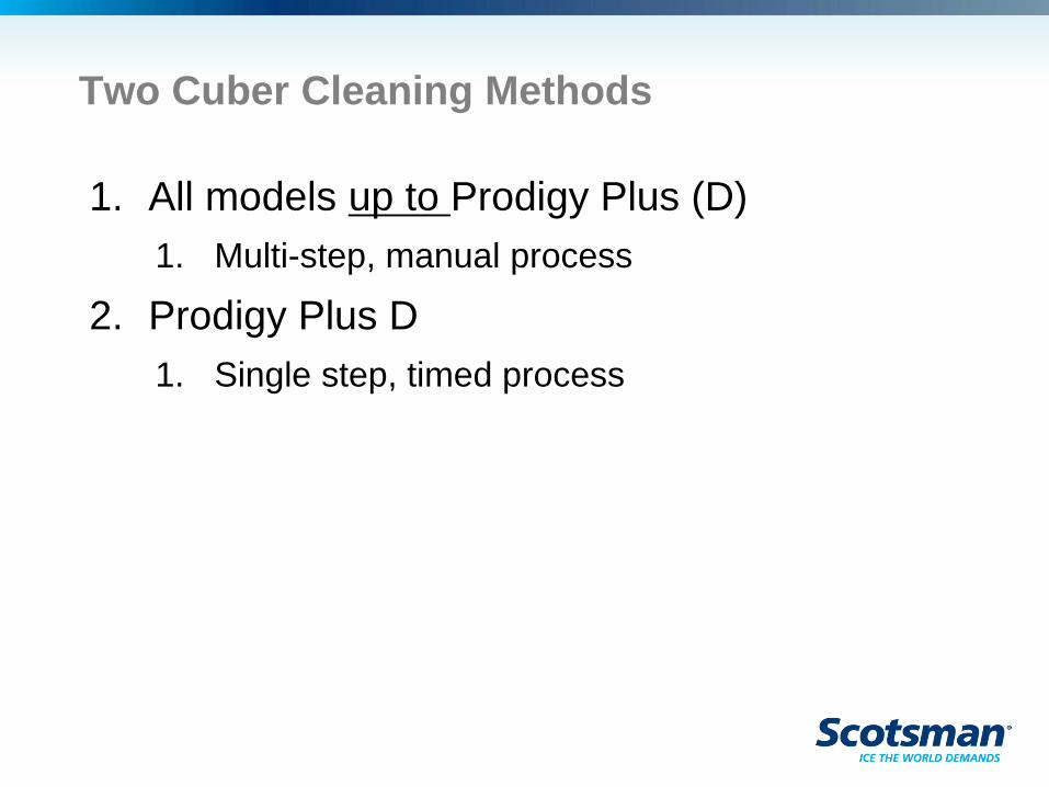
Two Cuber Cleaning Methods
1. All models up to Prodigy Plus (D)
1. Multi-step, manual process
2. Prodigy Plus D
1. Single step, timed process
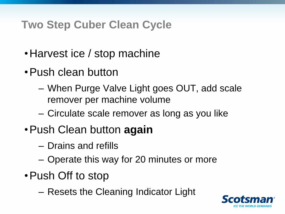
Two Step Cuber Clean Cycle
•Harvest ice / stop machine
•Push clean button
– When Purge Valve Light goes OUT, add scale
remover per machine volume
– Circulate scale remover as long as you like
•Push Clean button again
– Drains and refills
– Operate this way for 20 minutes or more
•Push Off to stop
– Resets the Cleaning Indicator Light
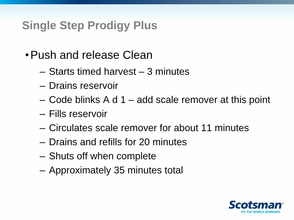
Single Step Prodigy Plus
•Push and release Clean
– Starts timed harvest – 3 minutes
– Drains reservoir
– Code blinks A d 1 – add scale remover at this point
– Fills reservoir
– Circulates scale remover for about 11 minutes
– Drains and refills for 20 minutes
– Shuts off when complete
– Approximately 35 minutes total
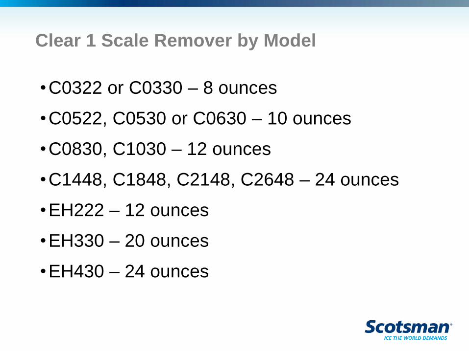
Clear 1 Scale Remover by Model
•C0322 or C0330 – 8 ounces
•C0522, C0530 or C0630 – 10 ounces
•C0830, C1030 – 12 ounces
•C1448, C1848, C2148, C2648 – 24 ounces
•EH222 – 12 ounces
•EH330 – 20 ounces
•EH430 – 24 ounces
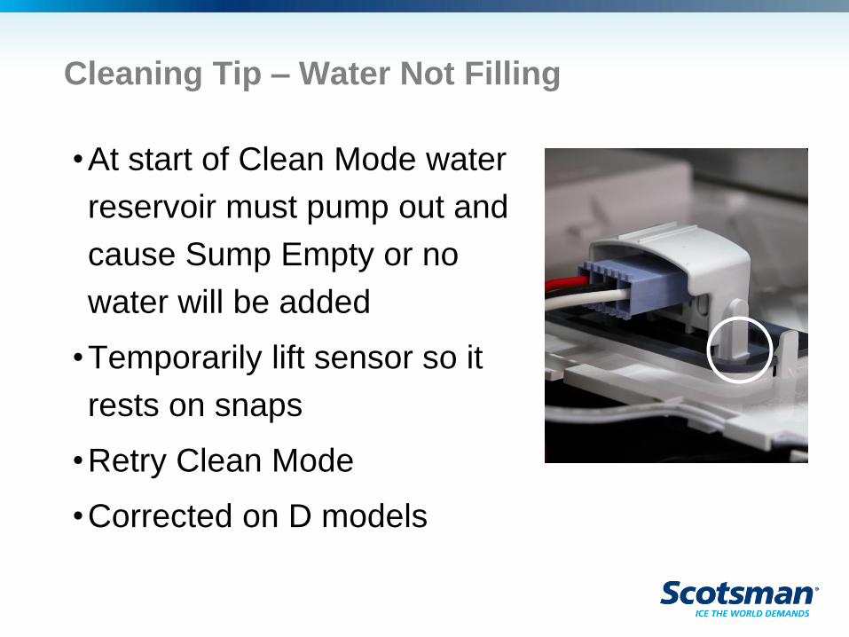
Cleaning Tip – Water Not Filling
•At start of Clean Mode water
reservoir must pump out and
cause Sump Empty or no
water will be added
•Temporarily lift sensor so it
rests on snaps
•Retry Clean Mode
•Corrected on D models
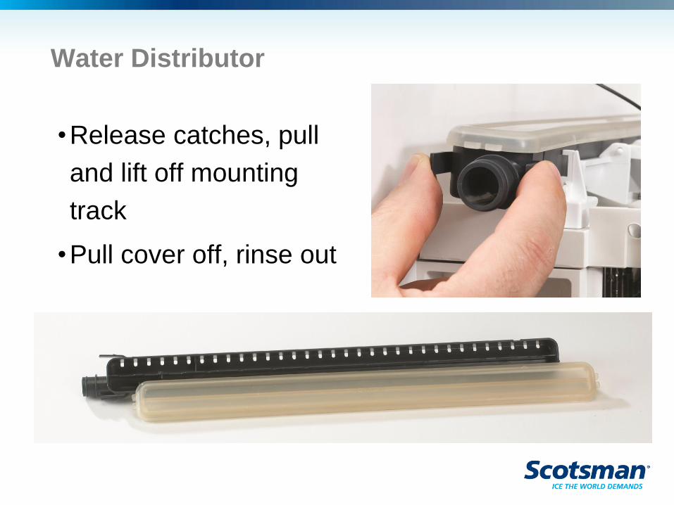
Water Distributor
•Release catches, pull
and lift off mounting
track
•Pull cover off, rinse out
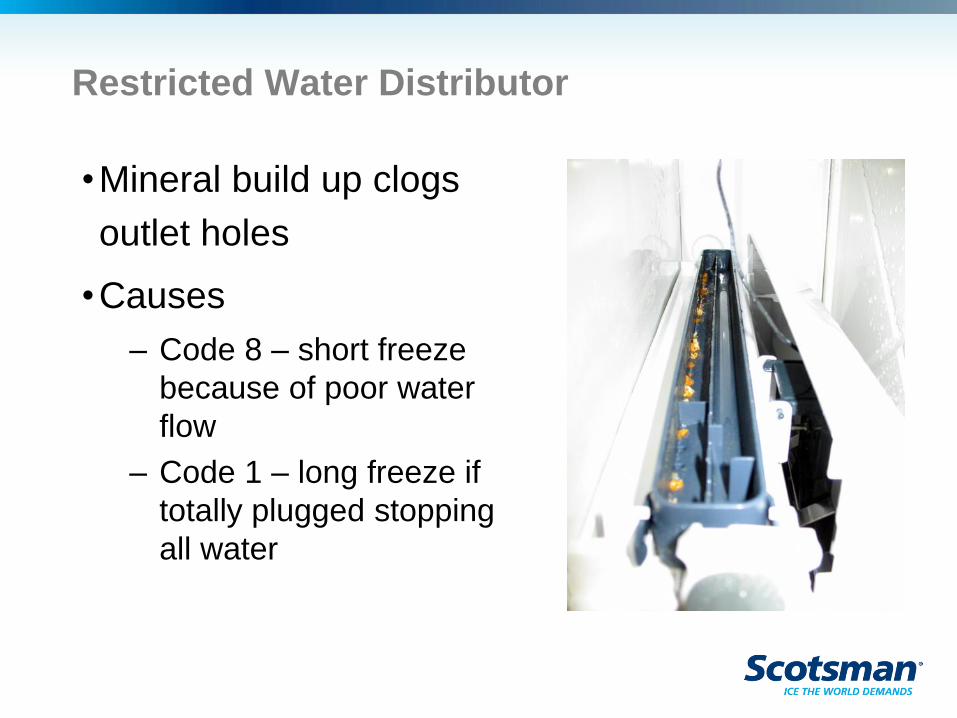
Restricted Water Distributor
•Mineral build up clogs
outlet holes
•Causes
– Code 8 – short freeze
because of poor water
flow
– Code 1 – long freeze if
totally plugged stopping
all water
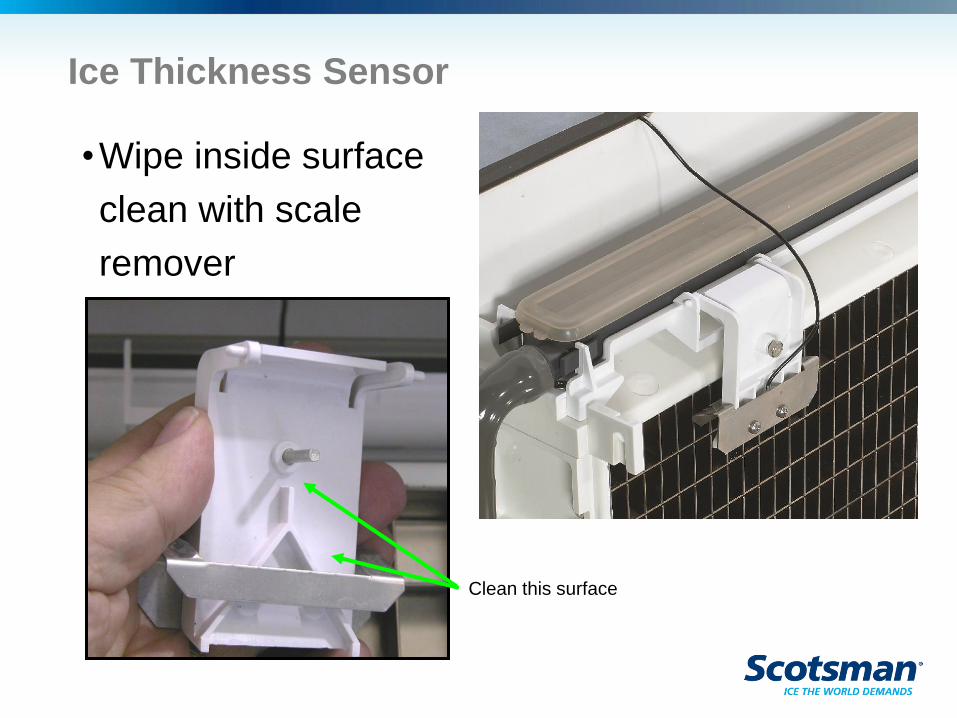
Ice Thickness Sensor
•Wipe inside surface
clean with scale
remover
Clean this surface
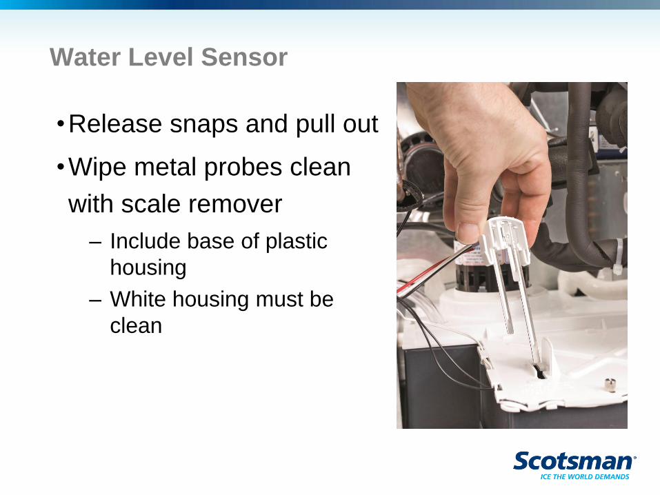
Water Level Sensor
•Release snaps and pull out
•Wipe metal probes clean
with scale remover
– Include base of plastic
housing
– White housing must be
clean
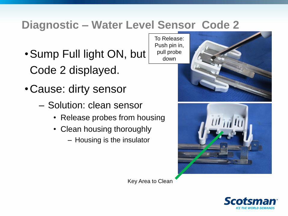
Diagnostic – Water Level Sensor Code 2
•Sump Full light ON, but no water in reservoir -
Code 2 displayed.
•Cause: dirty sensor
– Solution: clean sensor
• Release probes from housing
• Clean housing thoroughly
– Housing is the insulator
Key Area to Clean
To Release:
Push pin in,
pull probe
down
Additional Item to Clean
•Curtain – remove
•Right side liner - remove
•Sump cover – remove
•Pump – remove from bracket
•Pump bracket – remove
•Hose – remove
•Wash curtain, liner, sump cover, pump bracket
and hose in sink
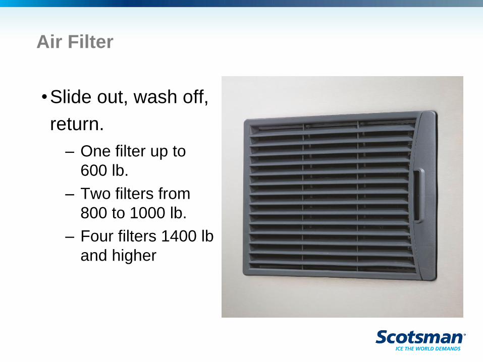
Air Filter
•Slide out, wash off,
return.
– One filter up to
600 lb.
– Two filters from
800 to 1000 lb.
– Four filters 1400 lb
and higher

Cuber Service and
Updates
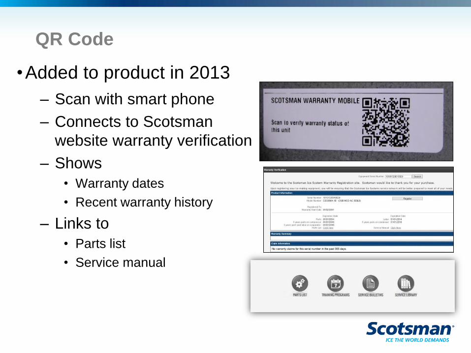
QR Code
•Added to product in 2013
– Scan with smart phone
– Connects to Scotsman
website warranty verification
– Shows
• Warranty dates
• Recent warranty history
– Links to
• Parts list
• Service manual
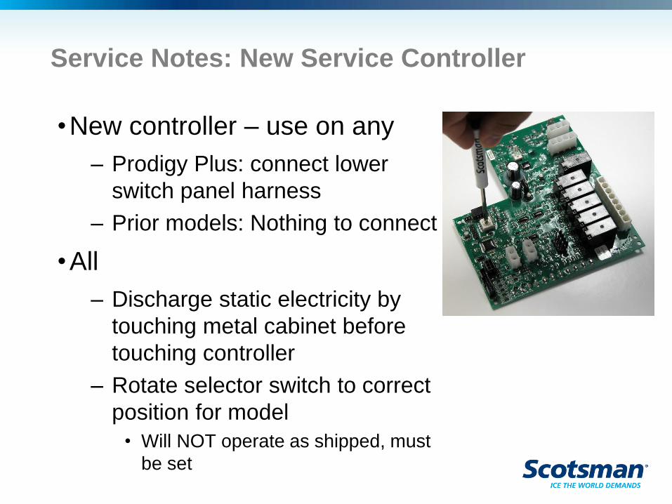
Service Notes: New Service Controller
•New controller – use on any
– Prodigy Plus: connect lower
switch panel harness
– Prior models: Nothing to connect
•All
– Discharge static electricity by
touching metal cabinet before
touching controller
– Rotate selector switch to correct
position for model
• Will NOT operate as shipped, must
be set
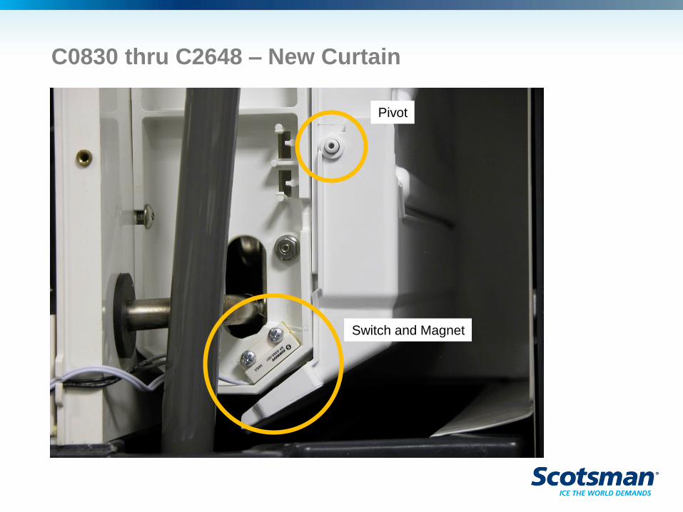
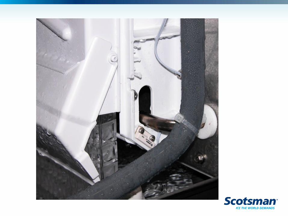
C0830 thru C2648 – New Curtain
Pivot
Switch and Magnet
Key Items to Remember
•Most common service is for a dirty machine
• Includes too short or too long freeze cycles
•Cleaning the machine with the Clean Mode
resets the clean light and resets the auto purge
Technical Service: 1-800-533-6006
www.scotsman-ice.com

Are there any questions?