Embed Size (px)
Citation preview
Installation and Basic 9304m Configuration Guide 9308m 9315m
ProCurve Routing Switches
www.procurve.com


Installation and Basic Configuration
Guide
for ProCurve 9300 Series Routing Switches
Software versions 07.8.00a or Greater
Copyright 2000, 2003, 2005 Hewlett-Packard Company, LP. The information contained herein is subject to change without notice.
Publication number
5990-6028
June 2005
Applicable Products
ProCurve 9304M (J4139A) ProCurve 9308M (J4138A) ProCurve 9315M (J4874A)
Trademark Credits
Microsoft®, Windows®, and Windows NT® are U.S. registered trademarks of Microsoft Corporation.
Adobe® and Acrobat® are trademarks of Adobe Systems Incorporated.
Disclaimer
The information contained in this document is subject to change without notice.
HEWLETT-PACKARD COMPANY MAKES NO WARRANTY OF ANY KIND WITH REGARD TO THIS MATERIAL, INCLUDING BUT NOT LIMITED TO, THE IMPLIED WARRANTIES OF MERCHANTABILITY AND FITNESS FOR A PARTICULAR PURPOSE. Hewlett-Packard shall not be liable for errors contained herein or for incidental or consequential damages in connection with the furnishing, performance or use of this material.
The only warranties for HP products and services are set forth in the express Warranty statements accompanying such products and services. Nothing herein should be construed as constituting an additional warranty. HP shall not be liable for technical or editorial errors or omissions contained herein.
Hewlett-Packard assumes no responsibility for the use or reliability of its software on equipment that is not furnished by Hewlett-Packard.
Warranty
See the Customer Support and Warranty booklet included with the product.
A copy of the specific warranty terms applicable to your Hewlett-Packard product and replacement parts can be obtained from your HP Sales and Service Office or authorized dealer.
Safety Considerations
Prior to the installation and use of this product, review all safety markings and instructions.
Instruction Manual Symbol.
If the product is marked with the above symbol, refer to the product manual to protect the product from damage.
WARNING Denotes a hazard that can cause injury.
CAUTION Denotes a hazard that can damage equipment or data.
Do not proceed beyond a WARNING or CAUTION notice until you have understood the hazard and have taken appropriate precautions.
Use of control, adjustments or performance procedures other than those specified herein may result in hazardous radiation exposure.
Grounding
This product provides a protective earthing terminal. There must be an uninterrupted safety earth ground from the main power source to the product’s input wiring terminals, power cord or supplied power cord set. Whenever it is likely that the protection has been impaired, disconnect the power cord until the ground has been restored.
If your LAN covers an area served by more than one power distribution system, be sure their safety grounds are securely interconnected.
LAN cables may occasionally be subject to hazardous transient voltages (such as lightning or disturbances in the electrical utilities power grid). Handle exposed metal components of the network with caution.
For more safety information, see “Safety and EMC Regulatory Statements”, beginning on page xix and the Quick Start Guide for your HP 9300M Routing Switch product.
Servicing
There are no user-serviceable parts inside the userinstallable modules comprising the product. Any servicing, adjustment, maintenance or repair must be performed only by service-trained personnel.
ii

Contents
Organization of Product Documentation............................................... xv
Safety and EMC Regulatory Statements............................................... xix Safety Information .................................................................................................................................... xix
Grounding .......................................................................................................................................... xix Servicing ............................................................................................................................................ xix
Informations concernant la sécurité ........................................................................................................... xx Hinweise zur Sicherheit ............................................................................................................................ xxi Considerazioni sulla sicurezza .................................................................................................................xxii Consideraciones sobre seguridad ...........................................................................................................xxiii Safety Information (Japan) ......................................................................................................................xxiv Safety Information (China) ....................................................................................................................... xxv Lasers ......................................................................................................................................................xxvi EMC Regulatory Statements ...................................................................................................................xxvi
U.S.A. ................................................................................................................................................xxvi Canada ..............................................................................................................................................xxvi Australia/New Zealand ......................................................................................................................xxvi Japan ................................................................................................................................................xxvi Korea ................................................................................................................................................xxvii Taiwan ..............................................................................................................................................xxvii Regulatory Model Identification Number ..........................................................................................xxvii
Chapter 1 Getting Started ........................................................................................ 1-1 Introduction ...............................................................................................................................................1-1 Software Versions Covered ......................................................................................................................1-1 Audience ...................................................................................................................................................1-1 Conventions ..............................................................................................................................................1-1 Terminology ..............................................................................................................................................1-2 Support and Warranty Information ...........................................................................................................1-2
June 2005 iii
Installation and Basic Configuration Guide for ProCurve 9300 Series Routing Switches
Related Publications .................................................................................................................................1-2
Chapter 2 Installation ............................................................................................... 2-1 Unpacking a System .................................................................................................................................2-1
Package Contents ..............................................................................................................................2-1 General Requirements .......................................................................................................................2-1
Installation Procedures .............................................................................................................................2-2 Summary ............................................................................................................................................2-2 Installation Precautions ......................................................................................................................2-3
Preparing the Installation Site ...................................................................................................................2-4 Cabling Infrastructure .........................................................................................................................2-4 Installation Location ...........................................................................................................................2-4
Installing (or Removing) Optional Modules ...............................................................................................2-4 Installing Modules ..............................................................................................................................2-4 Removing Modules ............................................................................................................................2-5
Installing and Removing (Optional) Mini-GBICs .......................................................................................2-6 Software Version and Management Module Requirement ................................................................2-6 Installing or Removing a Mini-GBIC ...................................................................................................2-6 Installation Notes ................................................................................................................................2-7 Software Support for Mini-GBIC Ports ...............................................................................................2-7
Removing and Installing XENPAK Optics ................................................................................................2-7 Removing a XENPAK Optic ...............................................................................................................2-7 Installing a XENPAK Optic .................................................................................................................2-8 Software Support for XENPAK Optics ...............................................................................................2-8
Cleaning the Fiber Optic Connectors .......................................................................................................2-8 Installing (or Removing) Redundant Power Supplies ...............................................................................2-8
Determining Power Supply Status .....................................................................................................2-8 Installing Power Supplies ...................................................................................................................2-9 Removing Power Supplies ...............................................................................................................2-10
Verifying Proper Operation .....................................................................................................................2-12 Attaching a PC or Terminal ....................................................................................................................2-13
Attaching a PC or Terminal Using a Serial Port ...............................................................................2-13 Attaching a PC or Terminal Using a Direct LAN Connection ...........................................................2-13
Assigning a Permanent Password ..........................................................................................................2-15 How To Assign a Password .............................................................................................................2-16
Assign a Permanent IP Address .............................................................................................................2-17 Mounting the Device ...............................................................................................................................2-18
Desktop Installation ..........................................................................................................................2-18 Rack Mount Installation ....................................................................................................................2-19
Connecting Power to the Device ............................................................................................................2-20 Connecting Network Devices .................................................................................................................2-20
Connectors .......................................................................................................................................2-21 Connecting to Other Switches, Routing Switches, and Ethernet Hubs ............................................2-22 Connecting to Workstations, Servers or Routing Switches ..............................................................2-23 Troubleshooting Network Connections ............................................................................................2-23
June 2005 iv
Contents
Verifying Proper Connections .................................................................................................................2-23 Pinging an IP Address ......................................................................................................................2-23 Tracing a Route ................................................................................................................................2-24
Managing the Device ..............................................................................................................................2-24 Logging on Through the CLI ............................................................................................................2-24 Searching and Filtering Output from CLI Commands ......................................................................2-26 Logging On Through the Web Management Interface .....................................................................2-31
Swapping Modules .................................................................................................................................2-33 Removing the Old Module ................................................................................................................2-33 Installing the New Module ................................................................................................................2-33
Next Steps ..............................................................................................................................................2-37
Chapter 3 Using Redundant Management Modules.............................................. 3-1 Configuration Considerations ...................................................................................................................3-1 Temperature Sensor .................................................................................................................................3-1 Switchover ................................................................................................................................................3-2
Management Sessions .......................................................................................................................3-2 Syslog and SNMP Traps ....................................................................................................................3-2 MAC Address Changes ......................................................................................................................3-2
Configuring the Redundant Management Parameters .............................................................................3-3 Installing Redundant Management Modules ......................................................................................3-3 Determining Redundant Management Module Status .......................................................................3-7 Displaying Switchover Messages .......................................................................................................3-9 File Synchronization Between the Active and Standby Redundant Management Modules .............3-10 Switching Over to the Standby Redundant Management Module ...................................................3-15
Chapter 4 Using the T-Flow Redundant Management Module............................. 4-1 Overview ...................................................................................................................................................4-1
Management and Co-Processing CPUs ............................................................................................4-1 Temperature Sensor ..........................................................................................................................4-2 Management Redundancy .................................................................................................................4-2 TSP Load Sharing ..............................................................................................................................4-3
Changing the Management Session from the MP to a TSP .....................................................................4-8 Logging In to a TSP ...........................................................................................................................4-8 Logging Out from the TSP .................................................................................................................4-8 TSP Commands .................................................................................................................................4-8
Displaying T-Flow Module Information .....................................................................................................4-9 Displaying the Software Version Running on the Module ..................................................................4-9 Displaying the Software Versions Installed on the Module ..............................................................4-10 Displaying General Module Information ...........................................................................................4-11 Determining Module Status ..............................................................................................................4-12 Determining the Slot Allocations for the TSPs .................................................................................4-14
June 2005 v

Installation and Basic Configuration Guide for ProCurve 9300 Series Routing Switches
Chapter 5 Using the 2-Port 10-Gigabit Ethernet Module ...................................... 5-1 1-Port 10 Gigabit Ethernet Module (Discontinued) ...................................................................................5-1
System Requirements ........................................................................................................................5-2 Hardware on the 1-Port 10 Gigabit Ethernet Module .........................................................................5-2 Features Not Supported on the 1-Port 10 Gigabit Ethernet Module ..................................................5-2 Replacing the Optics on the 1-Port 10 Gigabit Ethernet Module .......................................................5-2
2-Port 10-Gigabit Ethernet Modules with XENPAK Optics .......................................................................5-2 System Requirements ........................................................................................................................5-3 Hardware on the XENPAK-Based 10 Gigabit Ethernet Module .........................................................5-3 Features Not Supported on XENPAK-based 10 Gigabit Ethernet Modules .......................................5-3
Cleaning the Fiber Optic Connectors .......................................................................................................5-3 Cabling 10 Gigabit Ethernet Modules .......................................................................................................5-3 Port LEDs .................................................................................................................................................5-4 Troubleshooting Network Connections .....................................................................................................5-4 Link Fault Signaling (LFS) ........................................................................................................................5-5
Determining the 10 Gigabit Ethernet Module Installed in Your System .............................................5-6 Configuring Link Fault Signalling ........................................................................................................5-6
Remote Fault Notification (RFN) on Fiber Connections ...........................................................................5-6 Configuration Notes ...........................................................................................................................5-7 RFN Enhancements in 07.8.00 ..........................................................................................................5-7 Enabling Remote Fault Notification ....................................................................................................5-7 Viewing Which Fiber Ports Have RFN Enabled .................................................................................5-8
Upgrading an FPGA on a 10 Gigabit Ethernet Module ............................................................................5-8 Displaying the Installed FPGA Revisions ...........................................................................................5-9
Chapter 6 Configuring Basic Features ................................................................... 6-1 Using the Web Management Interface for Basic Configuration Changes ................................................6-2 Configuring Basic System Parameters .....................................................................................................6-3
Entering System Administration Information ......................................................................................6-3 Configuring Simple Network Management (SNMP) Parameters .......................................................6-4 Configuring an Interface as the Source for All Telnet Packets .........................................................6-10 Cancelling an Outbound Telnet Session ..........................................................................................6-11 Configuring an Interface as the Source for All TFTP Packets ..........................................................6-11 Specifying a Simple Network Time Protocol (SNTP) Server ............................................................6-11 Setting the System Clock .................................................................................................................6-13 Changing the Default Gigabit Negotiation Mode ..............................................................................6-15 Limiting Broadcast, Multicast, or Unknown-Unicast Rates ...............................................................6-17 Configuring CLI Banners ..................................................................................................................6-18 Configuring Terminal Display ...........................................................................................................6-19 Checking the Length of Terminal Displays .......................................................................................6-20
Configuring Basic Port Parameters ........................................................................................................6-20 Assigning a Port Name ....................................................................................................................6-22 Modifying Port Speed .......................................................................................................................6-23
June 2005 vi
Contents
Modifying Port Mode ........................................................................................................................6-24 Disabling or Re-Enabling a Port .......................................................................................................6-24 Disabling or Re-Enabling Flow Control ............................................................................................6-25 Changing the 802.3x Gigabit Negotiation Mode ..............................................................................6-26 Modifying Port Priority (QoS) ...........................................................................................................6-27
Configuring Basic Layer 2 Parameters ...................................................................................................6-27 Enabling or Disabling the Spanning Tree Protocol (STP) ................................................................6-27 Changing the MAC Age Time ..........................................................................................................6-30 Configuring Static MAC Entries ........................................................................................................6-31 Enabling Port-Based VLANs ............................................................................................................6-33 Defining MAC Address Filters ..........................................................................................................6-34 Defining Broadcast and Multicast Filters ..........................................................................................6-40 Locking a Port To Restrict Addresses ..............................................................................................6-42
Enabling or Disabling Routing Protocols ................................................................................................6-42 Displaying and Modifying System Parameter Default Settings ..............................................................6-43 Using the Temperature Sensor ..............................................................................................................6-47
Displaying the Temperature .............................................................................................................6-47 Displaying Temperature Messages ..................................................................................................6-48 Changing Temperature Warning and Shutdown Levels ..................................................................6-48 Changing the Chassis Polling Interval .............................................................................................6-49
Assigning a Mirror Port and Monitor Ports ..............................................................................................6-50 Configuration Guidelines for Monitoring Inbound Traffic ..................................................................6-50 Configuring Port Mirroring and Monitoring on 9300 Series Devices ................................................6-51 Monitoring an Individual Trunk Port .................................................................................................6-52 Monitoring 802.3ad Aggregate Links ...............................................................................................6-53 Mirror Ports for Policy-Based Routing (PBR) Traffic ........................................................................6-54 Displaying the Current Mirror and Monitor Port Configuration
on 9300 Series Devices .............................................................................................................6-55
Chapter 7 Configuring Trunk Groups and Dynamic Link Aggregation ............................................................ 7-1 Configuring Trunk Groups ........................................................................................................................7-1
Trunk Group Connectivity to a Server ................................................................................................7-2 Trunk Group Rules .............................................................................................................................7-3 Trunk Group Load Sharing .................................................................................................................7-8 Configuring a Trunk Group ...............................................................................................................7-11 Additional Trunking Options .............................................................................................................7-15 Server Trunk Group Load Sharing Enhancements and Options
(Release 07.7.00 and Higher) ...................................................................................................7-17 Enabling Optimized Server Trunk Load Balancing (T-Flow only) ....................................................7-19 Displaying Trunk Group Configuration Information ..........................................................................7-22
Dynamic Link Aggregation ......................................................................................................................7-27 Usage Notes ....................................................................................................................................7-27 Configuration Rules ..........................................................................................................................7-27 802.3ad Enhancements in Release 07.6.04 ....................................................................................7-29
June 2005 vii

Installation and Basic Configuration Guide for ProCurve 9300 Series Routing Switches
Enabling Link Aggregation ...............................................................................................................7-32 Link Aggregation Parameters ...........................................................................................................7-33 Displaying and Determining the Status of Aggregate Links .............................................................7-37 Clearing the Negotiated Link Aggregations ......................................................................................7-41
Chapter 8 Configuring Spanning Tree Protocol (STP) and Advanced STP Features ................................................................. 8-1 Configuring Standard STP Parameters ....................................................................................................8-1
STP Parameters and Defaults ...........................................................................................................8-2 Enabling or Disabling the Spanning Tree Protocol (STP) ..................................................................8-3 Changing STP Bridge and Port Parameters ......................................................................................8-4 Displaying STP Information ................................................................................................................8-8
Configuring Advanced STP Features .....................................................................................................8-19 Fast Port Span .................................................................................................................................8-19 Fast Uplink Span ..............................................................................................................................8-21 802.1W Rapid Spanning Tree (RSTP) .............................................................................................8-22 802.1W Draft 3 .................................................................................................................................8-58 Single Spanning Tree (SSTP) ..........................................................................................................8-62 SuperSpan™ ....................................................................................................................................8-64 STP per VLAN Group .......................................................................................................................8-71
PVST/PVST+ Compatibility ....................................................................................................................8-75 PVST/PVST+ Compatibility – 07.6.04 and Later .............................................................................8-75 PVST/PVST+ Compatibility – Earlier Than 07.6.01b .......................................................................8-81
Chapter 9 Configuring Uni-Directional Link Detection (UDLD)............................ 9-1 Configuration Considerations ...................................................................................................................9-1 Configuring UDLD ....................................................................................................................................9-2
Changing the Keepalive Interval ........................................................................................................9-2 Changing the Keepalive Retries .........................................................................................................9-2 UDLD for Tagged Ports ......................................................................................................................9-2
Displaying UDLD Information ...................................................................................................................9-3 Displaying Information for All Ports ....................................................................................................9-3 Displaying Information for a Single Port .............................................................................................9-4
Clearing UDLD Statistics ..........................................................................................................................9-5
Chapter 10 Configuring Metro Features................................................................. 10-1 Topology Groups ....................................................................................................................................10-1
Master VLAN and Member VLANs ..................................................................................................10-2 Control Ports and Free Ports ...........................................................................................................10-2 Configuration Considerations ...........................................................................................................10-2 Configuring a Topology Group .........................................................................................................10-3 Displaying Topology Group Information ...........................................................................................10-3
viii June 2005

Contents
Metro Ring Protocol (MRP) ....................................................................................................................10-5 MRP Rings Without Shared Interfaces (MRP Phase 1) ...................................................................10-6 MRP Rings with Shared Interfaces (MRP Phase 2) .........................................................................10-6 Ring Initialization ..............................................................................................................................10-8 How Ring Breaks Are Detected and Healed ..................................................................................10-10 Master VLANs and Customer VLANs ............................................................................................10-12 Configuring MRP ............................................................................................................................10-14 Using MRP Diagnostics .................................................................................................................10-15 Displaying MRP Information ...........................................................................................................10-16 MRP CLI Example ..........................................................................................................................10-19
Virtual Switch Redundancy Protocol (VSRP) .......................................................................................10-21 Layer 2 and Layer 3 Redundancy ..................................................................................................10-22 Master Election and Failover ..........................................................................................................10-22 VSRP-Aware Security Features .....................................................................................................10-26 VSRP Parameters ..........................................................................................................................10-26 Configuring Basic VSRP Parameters Using the CLI ......................................................................10-29 Configuring Optional VSRP Parameters Using the CLI .................................................................10-30 Displaying VSRP Information Using the CLI ..................................................................................10-37 Configuring VSRP Using the Web Management Interface ............................................................10-40 Displaying VSRP Statistics Using the Web Management Interface ...............................................10-43
Chapter 11 Configuring Virtual LANs (VLANs)...................................................... 11-1 Overview .................................................................................................................................................11-1
Types of VLANs ...............................................................................................................................11-1 Default VLAN ...................................................................................................................................11-4 802.1q Tagging ................................................................................................................................11-5 Spanning Tree Protocol (STP) .........................................................................................................11-7 Virtual Routing Interfaces .................................................................................................................11-8 VLAN and Virtual Routing Interface Groups ....................................................................................11-8 Dynamic, Static, and Excluded Port Membership ............................................................................11-8 Super Aggregated VLANs ..............................................................................................................11-10 Trunk Group Ports and VLAN Membership ...................................................................................11-11 Summary of VLAN Configuration Rules .........................................................................................11-11
Routing Between VLANs ......................................................................................................................11-11 Virtual Routing Interfaces ..............................................................................................................11-12 Bridging and Routing the Same Protocol Simultaneously
on the Same Device ................................................................................................................11-12 Routing Between VLANs Using Virtual Routing Interfaces ............................................................11-12 Dynamic Port Assignment ..............................................................................................................11-13 Assigning a Different VLAN ID to the Default VLAN ......................................................................11-13 Assigning Trunk Group Ports .........................................................................................................11-13 Configuring Port-Based VLANs ......................................................................................................11-13 Modifying a Port-Based VLAN .......................................................................................................11-17
Configuring IP Subnet, IPX Network and Protocol-Based VLANs ........................................................11-20 Configuration Example ...................................................................................................................11-20
June 2005 ix
Installation and Basic Configuration Guide for ProCurve 9300 Series Routing Switches
Routing Between VLANs Using Virtual Routing Interfaces .................................................................11-21 Configuring AppleTalk Cable VLANs ....................................................................................................11-28
Configuration Guidelines ................................................................................................................11-28 Configuration Example ...................................................................................................................11-29
Configuring Protocol VLANs With Dynamic Ports ................................................................................11-31 Aging of Dynamic Ports ..................................................................................................................11-31 Configuration Guidelines ................................................................................................................11-31 Configuring an IP, IPX, or AppleTalk Protocol VLAN with Dynamic Ports .....................................11-31 Configuring an IP Subnet VLAN with Dynamic Ports .....................................................................11-32 Configuring an IPX Network VLAN with Dynamic Ports .................................................................11-32
Configuring Uplink Ports Within a Port-Based VLAN ...........................................................................11-33 Configuring the Same IP Subnet Address on Multiple Port-Based VLANs ..........................................11-33
Using Separate ACLs on IP Follower Virtual Routing Interfaces ...................................................11-37 Configuring VLAN Groups and Virtual Routing Interface Groups .........................................................11-38
Configuring a VLAN Group ............................................................................................................11-38 Configuring a Virtual Routing Interface Group ...............................................................................11-39 Displaying the VLAN Group and Virtual Routing Interface Group Information ...............................11-40 Allocating Memory for More VLANs or Virtual Routing Interfaces .................................................11-41
Configuring Super Aggregated VLANs .................................................................................................11-42 Configuring Aggregated VLANs .....................................................................................................11-44 Verifying the Configuration .............................................................................................................11-46 Complete CLI Examples ................................................................................................................11-46
Configuring Private VLANs ...................................................................................................................11-49 Implementation Notes ....................................................................................................................11-50 Configuring a Private VLAN ...........................................................................................................11-50 Enabling Broadcast or Unknown Unicast Traffic to the Private VLAN ...........................................11-52 CLI Example for Figure 11.18 ........................................................................................................11-53
Dual-Mode VLAN Ports ........................................................................................................................11-54 EP Module Hardware Flooding for Layer 2 Multicast and Broadcast Packets .....................................11-56 Configuring VLANs Using the Web Management Interface .................................................................11-57
Configuring a Port-Based VLAN ....................................................................................................11-57 Configuring a Protocol-Based VLAN ..............................................................................................11-58 Configuring an IP Subnet VLAN .....................................................................................................11-59 Configuring an IPX Network VLAN ................................................................................................11-61 Configuring an AppleTalk Cable VLAN ..........................................................................................11-62
Displaying VLAN Information ................................................................................................................11-63 Displaying System-Wide VLAN Information ...................................................................................11-63 Displaying VLAN Information for Specific Ports .............................................................................11-64
Chapter 12 Configuring IP Multicast Traffic Reduction ........................................ 12-1 Enabling IP Multicast Traffic Reduction ..................................................................................................12-1
Changing the IGMP Mode ................................................................................................................12-2 Disabling IGMP on Individual Ports ..................................................................................................12-3 Modifying the Query Interval ............................................................................................................12-4 Modifying the Age Interval ................................................................................................................12-4
June 2005x
Contents
Filtering Multicast Groups ................................................................................................................12-4 Displaying IP Multicast Information ........................................................................................................12-5
Displaying Multicast Information on Routing Switches ...................................................................12-10 Displaying IP Multicast Statistics ....................................................................................................12-12 Clearing IP Multicast Statistics .......................................................................................................12-13 Clearing IGMP Group Flows ..........................................................................................................12-13
Chapter 13 Configuring GARP VLAN Registration Protocol (GVRP)........................................ 13-1 Application Examples .............................................................................................................................13-1
Dynamic Core and Fixed Edge ........................................................................................................13-2 Dynamic Core and Dynamic Edge ...................................................................................................13-3 Fixed Core and Dynamic Edge ........................................................................................................13-4 Fixed Core and Fixed Edge .............................................................................................................13-4
VLAN Names ..........................................................................................................................................13-4 Configuration Considerations .................................................................................................................13-4 Configuring GVRP ..................................................................................................................................13-5
Changing the GVRP Base VLAN ID ................................................................................................13-5 Increasing the Maximum Configurable Value of the Leaveall Timer ................................................13-6 Enabling GVRP ................................................................................................................................13-6 Disabling VLAN Advertising .............................................................................................................13-6 Disabling VLAN Learning .................................................................................................................13-7 Changing the GVRP Timers .............................................................................................................13-7
Converting a VLAN Created by GVRP into a Statically-Configured VLAN .............................................13-8 Displaying GVRP Information .................................................................................................................13-9
Displaying GVRP Configuration Information ....................................................................................13-9 Displaying GVRP VLAN Information ..............................................................................................13-12 Displaying GVRP Statistics ............................................................................................................13-14 Displaying CPU Utilization Statistics ..............................................................................................13-15 Displaying GVRP Diagnostic Information .......................................................................................13-17
Clearing GVRP Statistics ......................................................................................................................13-17 CLI Examples .......................................................................................................................................13-17
Dynamic Core and Fixed Edge ......................................................................................................13-17 Dynamic Core and Dynamic Edge .................................................................................................13-18 Fixed Core and Dynamic Edge ......................................................................................................13-19 Fixed Core and Fixed Edge ...........................................................................................................13-19
Chapter 14 Enabling the FDP and Reading Cisco Discovery Protocol (CDP) Packets........................................... 14-1 Using FDP ..............................................................................................................................................14-1
Configuring FDP ...............................................................................................................................14-1 Displaying FDP Information .............................................................................................................14-2 Clearing FDP and CDP Information .................................................................................................14-5
June 2005 xi
Installation and Basic Configuration Guide for ProCurve 9300 Series Routing Switches
Reading CDP Packets ............................................................................................................................14-5 Enabling Interception of CDP Packets Globally ...............................................................................14-6 Enabling Interception of CDP Packets on an Interface ....................................................................14-6 Displaying CDP Information .............................................................................................................14-6 Clearing CDP Information ................................................................................................................14-8
Chapter 15 Updating Software Images and Configuration Files ............................................................................... 15-1 Determining the Software Versions Installed and Running on a Device ................................................15-1
Determining the Flash Image Version Running on the Device ........................................................15-1 Determining the Boot Image Version Running on the Device ..........................................................15-2 Determining the Image Versions Installed in Flash Memory ............................................................15-2
Image File Types ....................................................................................................................................15-2 Upgrading Software in Release 07.6.04 and Later .................................................................................15-3 Upgrading Software (Non-T-Flow) ..........................................................................................................15-3
Upgrading the Boot Code .................................................................................................................15-4 Upgrading the Flash Code ...............................................................................................................15-4
Upgrading Software (T-Flow) .................................................................................................................15-5 Upgrading the MP Boot Code ..........................................................................................................15-5 Upgrading the TSP Boot Code .........................................................................................................15-5 Upgrading the MP Flash Code .........................................................................................................15-6 Upgrading the TSP Flash Code .......................................................................................................15-6 Changing the Default Boot Source ...................................................................................................15-7
Using SNMP to Upgrade Software .........................................................................................................15-8 Upgrading Switching Processors on a Routing Switch ....................................................................15-8
Changing the Block Size for TFTP File Transfers ..................................................................................15-9 Rebooting .............................................................................................................................................15-10 Loading and Saving Configuration Files ...............................................................................................15-11
Replacing the Startup Configuration with the Running Configuration ............................................15-12 Replacing the Running Configuration with the Startup Configuration ............................................15-12 Logging Changes to the Startup-Config File ..................................................................................15-12 Copying a Configuration File to or from a TFTP Server .................................................................15-13 Dynamic Configuration Loading .....................................................................................................15-14 Maximum File Sizes for Startup-Config File and Running-Config ..................................................15-16 Using SNMP to Save and Load Configuration Information ............................................................15-17 Erasing Image and Configuration Files ..........................................................................................15-18
Scheduling a System Reload ...............................................................................................................15-18 Reloading at a Specific Time .........................................................................................................15-18 Reloading after a Specific Amount of Time ....................................................................................15-19 Displaying the Amount of Time Remaining Before a Scheduled Reload .......................................15-19 Canceling a Scheduled Reload ......................................................................................................15-19
Diagnostic Error Codes and Remedies for TFTP Transfers .................................................................15-20
June 2005 xii

Contents
APPENDIX A Using Syslog ...........................................................................................A-1 Overview .................................................................................................................................................. A-1 Displaying Syslog Messages ................................................................................................................... A-2 Configuring the Syslog Service ............................................................................................................... A-3
Displaying the Syslog Configuration ................................................................................................. A-3 Displaying and Configuring Syslog Buffer Parameters Using the Web
Management Interface ................................................................................................................ A-7 Disabling or Re-Enabling Syslog ....................................................................................................... A-9 Specifying a Syslog Server ............................................................................................................... A-9 Specifying an Additional Syslog Server ............................................................................................ A-9 Disabling Logging of a Message Level ........................................................................................... A-10 Changing the Number of Entries the Local Buffer Can Hold ........................................................... A-10 Changing the Log Facility ................................................................................................................ A-11 Displaying the Interface Name in Syslog Messages ....................................................................... A-12 Clearing the Syslog Messages from the Local Buffer ..................................................................... A-12 Displaying TCP/UDP Port Numbers in Syslog Messages .............................................................. A-12
Syslog Messages .................................................................................................................................. A-13
APPENDIX B Enhanced Performance (EP) Chassis Modules ...................................B-1 Determining Your Device Type ................................................................................................................ B-1 EP Modules ............................................................................................................................................. B-1 The EP Management Module .................................................................................................................. B-2
Hardware Overview ........................................................................................................................... B-2 J4885A EP Management Module ..................................................................................................... B-3
EP Gigabit Ethernet Forwarding Module ................................................................................................. B-4 J4895A 16-Port Forwarding Module ................................................................................................. B-4
EP 10/100 Ethernet Forwarding Modules ................................................................................................ B-4 J4881A/B 48-Port Enterprise Forwarding Module ............................................................................. B-4 J4889A/B 48-Port Telco Forwarding Module .................................................................................... B-5
Configuration Considerations .................................................................................................................. B-7
APPENDIX C Software Specifications .........................................................................C-1 IEEE Compliance .................................................................................................................................... C-1 RFC Support ............................................................................................................................................ C-2 Internet Drafts .......................................................................................................................................... C-4
APPENDIX D Hardware Specifications ........................................................................D-1 Control Features ...................................................................................................................................... D-1
Control Panels ................................................................................................................................... D-1 Ports .................................................................................................................................................. D-2 LEDs ................................................................................................................................................. D-3
June 2005 xiii
Installation and Basic Configuration Guide for ProCurve 9300 Series Routing Switches
Reset Button ..................................................................................................................................... D-3 Power Specifications ............................................................................................................................... D-4 Physical Dimensions ............................................................................................................................... D-4 Operating Environment ............................................................................................................................ D-5 Storage Environment ............................................................................................................................... D-5 Electromagnetic Emissions ..................................................................................................................... D-5 Safety Agency Approvals ........................................................................................................................ D-5 Laser ........................................................................................................................................................ D-5
APPENDIX E Cautions and Warnings..........................................................................E-1 Cautions .................................................................................................................................................. E-1 Warnings ................................................................................................................................................. E-7
INDEX ..................................................................................................Index-1
xiv June 2005

Organization of Product Documentation
NOTE: HP periodically updates the ProCurve 9300/9400 Series Routing Switch documentation. For the latest version of any of these publications, visit the ProCurve website at:
http://www.procurve.com
Click on Technical Support, then Product manuals.
NOTE: All manuals listed below are available on the ProCurve website, and also on the Documentation CD shipped with your HP product.
Installation and Basic Configuration Guide for ProCurve 9300 Series Routing Switches This is an electronic (PDF) guide containing product safety and EMC regulatory statements as well as installation and basic configuration information, and software and hardware specifications.
Topics Specific to the 9300 Series Routing Switches • Product mounting instructions
• Module installation
• Basic access and connectivity configuration (passwords, IP addresses)
• Redundant management module commands and file systems
• Cooling system commands and information
• Basic software feature configuration (SNMP, clock, mirror/monitor ports)
• Configuring for these features:
• Uni-Directional Link Detection (UDLD)
• Metro Ring Protocol (MRP)
• Virtual Switch Redundancy Protocol (VSRP)
• GVRP (dynamic VLANs)
• Software update instructions
• Hardware specs
• Software specs (e.g. RFC support, IEEE compliance)
June 2005 xv
Installation and Basic Configuration Guide for ProCurve 9300 Series Routing Switches
Information on Configuring Features for 9300 Series and 9408sl Routing Switches • Port settings
• VLANS
• Trunks
• Spanning Tree Protocol
• Syslog
Quick Start Guide for ProCurve 9300 Series Routing Switches This is a printed guide you can use as an easy reference to the installation and product safety information needed for out-of-box setup, plus the general product safety and EMC regulatory statements of which you should be aware when installing and using a Routing Switch.
Installation and Basic Configuration Guide for the ProCurve 9408sl Routing Switch This is a printed guide that describes the ProCurve 9408sl and provides procedures for installing modules and AC power supplies into the ProCurve 9408sl, cabling the 10-Gigabit Ethernet interface ports, and performing a basic configuration of the software.
Topics Specific to the 9408sl Routing Switch • Product overview and architecture
• Product mounting instructions
• Module installation
• Basic access and connectivity configuration (passwords, IP addresses)
• Management Module redundancy and file systems
• Interacting with the cooling system, switch fabric module, and interface modules
• Basic software feature configuration (SNMP, clock, mirror/monitor ports)
• Hardware maintenance instructions
• Software update instructions
• Hardware specs
• Safety and regulatory statements
• Software specs (e.g. RFC support, IEEE compliance)
Advanced Configuration and Management Guide for ProCurve 9300/9400 Series Routing Switches This is an electronic (PDF) guide that contains advanced configuration information for routing protocols and Quality of Service (QoS). In addition, appendixes in this guide contain reference information for network monitoring, policies, and filters.
Information on Configuring Features • Quality of Service (QoS)
• Access Control Lists (ACLs)
• Rate limiting
• IPv4 routing
• RIP
• IP Multicast
• OSPF
• BGP4
• Multi-protocol BGP (MBGP)
• Network Address Translation (NAT)
xvi June 2005
• VRRP and VRRPE (VRRP extended)
• IPX routing
• AppleTalk routing
• Route health injection
• RMON, NetFlow, and sFlow monitoring
IPv6 Configuration Guide for the ProCurve 9408sl Routing Switch This is an electronic (PDF) guide that describes the IPv6 software and features. It provides conceptual information about IPv6 addressing and explains how to configure basic IPv6 connectivity and the IPv6 routing protocols. The software procedures explain how to perform tasks using the CLI.
Command Line Interface Reference for ProCurve 9300/9400 Series Routing Switches This is an electronic (PDF) guide that provides a dictionary of CLI commands and syntax.
Security Guide for ProCurve 9300/9400 Series Routing Switches This is an electronic (PDF) guide that provides procedures for securing management access to HP devices and for protecting against Denial of Service (DoS) attacks.
Diagnostic Guide for ProCurve 9300/9400 Series Routing Switches This is an electronic (PDF) guide that describes the diagnostic commands available on HP devices. The software procedures show how to perform tasks using the Command Line Interface (CLI).
Removing and Installing XENPAK Optics This is a printed instruction sheet describing the correct preparation and procedure for removing and installing XENPAK optics on the 10-Gigabit Ethernet modules.
Read Me First The "Read Me First" document, printed on bright yellow paper, is included with every chassis and module. It contains an overview of software release information, a brief "Getting Started" section, an included parts list, troubleshooting tips, operating notes, and other information that is not included elsewhere in the product documentation. It also includes:
• software update instructions
• operating notes for this release
Release Notes These documents describe features and other information that becomes available between revisions of the main product guides. New releases of such documents will be available on HP's ProCurve website. To register to receive email notice from HP when a new software release is available, visit:
http://www.procurve.com
In the "My Procurve" box on the right, click on "Register".
Product Documentation CD: A Tool for Finding Specific Information and/or Printing Selected Pages This CD is shipped with your ProCurve Routing Switch product and provides the following:
• A README file describing the CD contents and use, including easy instructions on how to search the book files for specific information
• A Contents file to give you easy access to the documentation on the CD
• Separate PDF files of the individual chapters and appendixes in the major guides, enabling you to easily print individual chapters, appendixes, and selected pages
• Single PDF files for each of the major guides, enabling you to use the Adobe® Acrobat® Reader to easily search for detailed information
• Additional files. These may include such items as additional Read Me files and release notes.
June 2005 xvii

Installation and Basic Configuration Guide for ProCurve 9300 Series Routing Switches
xviii June 2005

Safety and EMC Regulatory Statements
Safety Information
Documentation reference symbol. If the product is marked with this symbol, refer to the product documentation to get ! more information about the product.
WARNING A WARNING in the manual denotes a hazard that can cause injury or death.
CAUTION A CAUTION in the manual denotes a hazard that can damage equipment.
Do not proceed beyond a WARNING or CAUTION notice until you have understood the hazardous conditions and have taken appropriate steps.
Grounding These are safety class I products and have protective earthing terminals. There must be an uninterruptible safety earth ground from the main power source to the product's input wiring terminals, power cord, or supplied power cord set. Whenever it is likely that the protection has been impaired, disconnect the power cord until the ground has been restored.
For LAN cable grounding:
• If your LAN covers an area served by more than one power distribution system, be sure their safety grounds are securely interconnected.
• LAN cables may occasionally be subject to hazardous transient voltages (such as lightning or disturbances in the electrical utilities power grid). Handle exposed metal components of the network with caution.
Servicing There are no user-serviceable parts inside these products. Any servicing, adjustment, maintenance, or repair must be performed only by service-trained personnel.
These products do not have a power switch; they are powered on when the power cord is plugged in.
June 2005 xix

Installation and Basic Configuration Guide for ProCurve 9300 Series Routing Switches
Informations concernant la sécurité
Symbole de référence à la documentation. Si le produit est marqué de ce symbole, reportez-vous à la documentation du ! produit afin d'obtenir des informations plus détaillées.
WARNING Dans la documentation, un WARNING indique un danger susceptible d'entraîner des dommages corporels ou la mort.
CAUTION Un texte de mise en garde intitulé CAUTION indique un danger susceptible de causer des dommages à l'équipement.
Ne continuez pas au-delà d'une rubrique WARNING ou CAUTION avant d'avoir bien compris les conditions présentant un danger et pris les mesures appropriées.
Cet appareil est un produit de classe I et possède une borne de mise à la terre. La source d'alimentation principale doit être munie d'une prise de terre de sécurité installée aux bornes du câblage d'entrée, sur le cordon d'alimentation ou le cordon de raccordement fourni avec le produit. Lorsque cette protection semble avoir été endommagée, débrancher le cordon d'alimentation jusqu'à ce que la mise à la terre ait été réparée.
Mise à la terre du câble de réseau local:
• si votre réseau local s'étend sur une zone desservie par plus d'un système de distribution de puissance, assurez-vous que les prises de terre de sécurité soient convenablement interconnectées.
• Les câbles de réseaux locaux peuvent occasionnellement être soumis à des surtensions transitoires dangereuses (telles que la foudre ou des perturbations dans le réseau d'alimentation public). Manipulez les composants métalliques du réseau avec précautions.
Aucune pièce contenue à l'intérieur de ce produit ne peut être réparée par l'utilisateur. Tout dépannage, réglage, entretien ou réparation devra être confié exclusivement à un personnel qualifié.
Cet appareil ne comporte pas de commutateur principal ; la mise sous tension est effectuée par branchement du cordon d'alimentation.
June 2005 xx
Hinweise zur Sicherheit
! Symbol für Dokumentationsverweis. Wenn das Produkt mit diesem Symbol markiert ist, schlagen Sie bitte in der Produktdokumentation nach, um mehr Informationen über das Produkt zu erhalten.
WARNING Symbol für Dokumentationsverweis. Wenn das Produkt mit diesem Symbol markiert ist, schlagen Sie bitte in der Produktdokumentation nach, um mehr Informationen über das Produkt zu erhalten.
CAUTION Symbol für Dokumentationsverweis. Wenn das Produkt mit diesem Symbol markiert ist, schlagen Sie bitte in der Produktdokumentation nach, um mehr Informationen über das Produkt zu erhalten.
Fahren Sie nach dem Hinweis WARNING oder CAUTION erst fort, nachdem Sie den Gefahrenzustand verstanden und die entsprechenden Maßnahmen ergriffen haben.
Dies ist ein Gerät der Sicherheitsklasse I und verfügt über einen schützenden Erdungsterminal. Der Betrieb des Geräts erfordert eine ununterbrochene Sicherheitserdung von der Hauptstromquelle zu den Geräteingabeterminals, den Netzkabeln oder dem mit Strom belieferten Netzkabelsatz voraus. Sobald Grund zur Annahme besteht, daß der Schutz beeinträchtigt worden ist, das Netzkabel aus der Wandsteckdose herausziehen, bis die Erdung wiederhergestellt ist.
Für LAN-Kabelerdung:
• Wenn Ihr LAN ein Gebiet umfaßt, das von mehr als einem Stromverteilungssystem beliefert wird, müssen Sie sich vergewissern, daß die Sicherheitserdungen fest untereinander verbunden sind.
• LAN-Kabel können gelegentlich gefährlichen Übergangsspannungen ausgesetzt werden (beispielsweise durch Blitz oder Störungen in dem Starkstromnetz des Elektrizitätswerks). Bei der Handhabung exponierter Metallbestandteile des Netzwerkes Vorsicht walten lassen.
Dieses Gerät enthält innen keine durch den Benutzer zu wartenden Teile. Wartungs-, Anpassungs-, Instandhaltungs- oder Reparaturarbeiten dürfen nur von geschultem Bedienungspersonal durchgeführt werden.
Dieses Gerät hat keinen Netzschalter; es wird beim Anschließen des Netzkabels eingeschaltet.
June 2005 xxi
Installation and Basic Configuration Guide for ProCurve 9300 Series Routing Switches
Considerazioni sulla sicurezza
Simbolo di riferimento alla documentazione. Se il prodotto è contrassegnato da questo simbolo, fare riferimento alla ! documentazione sul prodotto per ulteriori informazioni su di esso.
WARNING La dicitura WARNINGdenota un pericolo che può causare lesioni o morte.
CAUTION La dicituraCAUTION denota un pericolo che può danneggiare le attrezzature.
Non procedere oltre un avviso di WARNING o di CAUTIONprima di aver compreso le condizioni di rischio e aver provveduto alle misure del caso.
Questo prodotto è omologato nella classe di sicurezza I ed ha un terminale protettivo di collegamento a terra. Dev'essere installato un collegamento a terra di sicurezza, non interrompibile che vada dalla fonte d'alimentazione principale ai terminali d'entrata, al cavo d'alimentazione oppure al set cavo d'alimentazione fornito con il prodotto. Ogniqualvolta vi sia probabilità di danneggiamento della protezione, disinserite il cavo d'alimentazione fino a quando il collegaento a terra non sia stato ripristinato.
Per la messa a terra dei cavi LAN:
• se la vostra LAN copre un'area servita da più di un sistema di distribuzione elettrica, accertatevi che i collegamenti a terra di sicurezza siano ben collegati fra loro;
• i cavi LAN possono occasionalmente andare soggetti a pericolose tensioni transitorie (ad esempio, provocate da lampi o disturbi nella griglia d'alimentazione della società elettrica); siate cauti nel toccare parti esposte in metallo della rete.
Nessun componente di questo prodotto può essere riparato dall'utente. Qualsiasi lavoro di riparazione, messa a punto, manutenzione o assistenza va effettuato esclusivamente da personale specializzato.
Questo apparato non possiede un commutatore principale; si mette scotto tensione all'inserirsi il cavo d'alimentazione.
xxii June 2005
Consideraciones sobre seguridad
Símbolo de referencia a la documentación. Si el producto va marcado con este símbolo, consultar la documentación del ! producto a fin de obtener mayor información sobre el producto.
WARNING Una WARNING en la documentación señala un riesgo que podría resultar en lesiones o la muerte.
CAUTION Una CAUTION en la documentación señala un riesgo que podría resultar en averías al equipo.
No proseguir después de un símbolo de WARNING o CAUTION hasta no haber entendido las condiciones peligrosas y haber tomado las medidas apropiadas.
Este aparato se enmarca dentro de la clase I de seguridad y se encuentra protegido por una borna de puesta a tierra. Es preciso que exista una puesta a tierra continua desde la toma de alimentación eléctrica hasta las bornas de los cables de entrada del aparato, el cable de alimentación o el juego de cable de alimentación suministrado. Si existe la probabilidad de que la protección a tierra haya sufrido desperfectos, desenchufar el cable de alimentación hasta haberse subsanado el problema.
Puesta a tierra del cable de la red local (LAN):
• Si la LAN abarca un área cuyo suministro eléctrico proviene de más de una red de distribución de electricidad, cerciorarse de que las puestas a tierra estén conectadas entre sí de modo seguro.
• Es posible que los cables de la LAN se vean sometidos de vez en cuando a voltajes momentáneos que entrañen peligro (rayos o alteraciones en la red de energía eléctrica). Manejar con precaución los componentes de metal de la LAN que estén al descubierto.
Este aparato no contiene pieza alguna susceptible de reparación por parte del usuario. Todas las reparaciones, ajustes o servicio de mantenimiento debe realizarlos solamente el técnico.
Este producto no tiene interruptor de potencia; se activa cuando se enchufa el cable de alimentación.
June 2005 xxiii
Installation and Basic Configuration Guide for ProCurve 9300 Series Routing Switches
Safety Information (Japan)
xxiv June 2005
Safety Information (China)
June 2005 xxv

Installation and Basic Configuration Guide for ProCurve 9300 Series Routing Switches
Lasers The Gigabit-SX, Gigabit-LX, and Gigabit LH-LC Modules are Class 1 Laser Products.
Laser Klasse 1
The modules comply with IEC 60825-1, IEC 60825-2
EMC Regulatory Statements
U.S.A. FCC Class A
This equipment has been tested and found to comply with the limits for a Class A digital device, pursuant to Part 15 of the FCC Rules. These limits are designed to provide reasonable protection against interference when the equipment is operated in a commercial environment. This equipment generates, uses, and can radiate radio frequency energy and, if not installed and used in accordance with the instruction manual, may cause interference to radio communications. Operation of this equipment in a residential area may cause interference in which case the user will be required to correct the interference at his own expense.
Canada This product complies with Class A Canadian EMC requirements.
Australia/New Zealand This product complies with Australia/New Zealand EMC Class A requirements.
Japan VCCI Class A
xxvi June 2005

Korea
Taiwan
Regulatory Model Identification Number
For regulatory identification purposes, the HP ProCurve Routing Switch 9315M has been assigned a Regulatory Model Number. The Regulatory Model Number for this routing switch is RSVLC-0203.
This regulatory number should not be confused with the marketing name (HP ProCurve Routing Switch 9315M), or product numbers (J4874A, J4875A).
June 2005 xxvii

Installation and Basic Configuration Guide for ProCurve 9300 Series Routing Switches
xxviii June 2005

Chapter 1 Getting Started
Introduction
NOTE: This Installation and Basic Configuration Guide for ProCurve 9300 Series Routing Switches is intended as a supplement to the printed Quick Start Guide included with your Routing Switch chassis. The printed Quick Start Guide is the primary document for unpacking a ProCurve Routing Switch and performing the Routing Switch installation. The latest version of the Quick Start Guide is available on the ProCurve Web site:
http://www.procurve.com (Click on Technical Support, then Product Manuals.)
This guide describes how to install, configure, and monitor the following devices:
• ProCurve Routing Switch 9315M
• ProCurve Routing Switch 9308M
• ProCurve Routing Switch 9304M
Software Versions Covered This edition describes software release 07.8.00a for the following ProCurve products:
• 9304M
• 9308M
• 9315M
Audience This manual is designed for system administrators with a working knowledge of Layer 2 and Layer 3 switching and routing.
If you are using a ProCurve Routing Switch, you should be familiar with the following protocols if applicable to your network—IP, RIP, OSPF, BGP4, IGMP, PIM, DVMRP, IPX, AppleTalk, and VRRP.
Conventions This guide uses the following typographical conventions:
Italic highlights the title of another publication and occasionally emphasizes a word or phrase.
June 2005 1 - 1

Installation and Basic Configuration Guide for ProCurve 9300 Series Routing Switches
Bold highlights a CLI command.
Bold Italic highlights a term that is being defined.
Underline highlights a link on the Web management interface.
Capitals highlights field names and buttons that appear in the Web management interface.
NOTE: A note emphasizes an important fact or calls your attention to a dependency.
WARNING: A warning calls your attention to a possible hazard that can cause injury or death.
CAUTION: A caution calls your attention to either a possible hazard that can damage equipment or an action that can produce an operating problem or other unwanted results.
Terminology The following table defines basic product terms used in this guide.
Term
chassis
or
Chassis device
EP
and
Standard
Routing Switch
or
router
Switch
ProCurveRS#
Definition
A Routing Switch that accepts optional modules or power supplies. The ProCurve 9304M, 9308M, 9315M, and 9408sl Routing Switches are Chassis devices.
9300 Series Chassis devices can be EP or Standard devices, depending on whether the management module is an EP or Standard module.
A Layer 2 and Layer 3 device that switches and routes network traffic. The term router is sometimes used in this document in descriptions of a Routing Switch’s Layer 3 routing protocol features.
A Layer 2 device that switches network traffic.
An example Command Line Interface (CLI) prompt. Actual prompts show the product number for the device, such as HP9304#.
Support and Warranty Information Refer to Support is as Close as the World Wide Web, which was shipped with your ProCurve Routing Switch.
Related Publications Refer to the “Organization of Product Documentation” on page xv for a list of publications for your ProCurve Routing Switch.
1 - 2 June 2005
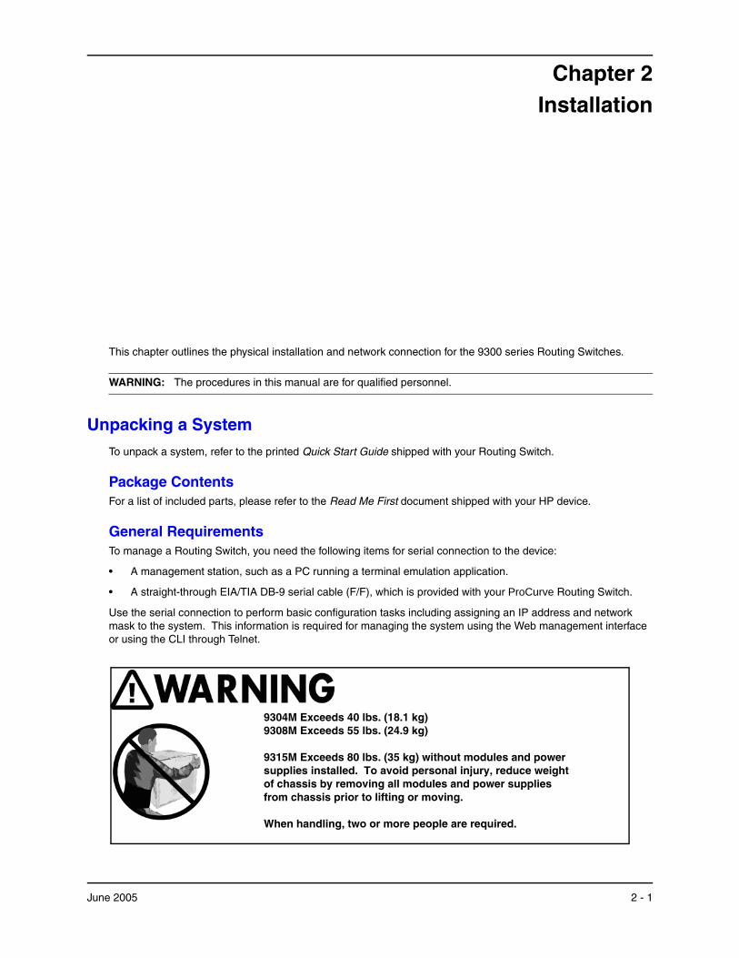
Chapter 2 Installation
This chapter outlines the physical installation and network connection for the 9300 series Routing Switches.
WARNING: The procedures in this manual are for qualified personnel.
Unpacking a System To unpack a system, refer to the printed Quick Start Guide shipped with your Routing Switch.
Package Contents For a list of included parts, please refer to the Read Me First document shipped with your HP device.
General Requirements To manage a Routing Switch, you need the following items for serial connection to the device:
• A management station, such as a PC running a terminal emulation application.
• A straight-through EIA/TIA DB-9 serial cable (F/F), which is provided with your ProCurve Routing Switch.
Use the serial connection to perform basic configuration tasks including assigning an IP address and network mask to the system. This information is required for managing the system using the Web management interface or using the CLI through Telnet.
9304M Exceeds 40 lbs. (18.1 kg) 9308M Exceeds 55 lbs. (24.9 kg)
9315M Exceeds 80 lbs. (35 kg) without modules and power supplies installed. To avoid personal injury, reduce weight of chassis by removing all modules and power supplies from chassis prior to lifting or moving.
When handling, two or more people are required.
June 2005 2 - 1
Installation and Basic Configuration Guide for ProCurve 9300 Series Routing Switches
WARNING: Do not use the extraction handles on the power supply units to lift or carry the 9300 series Routing Switch. The power supply extraction handles are not intended to support the weight of the system and must never be used to lift or move the chassis.
Installation Procedures
Summary Follow the steps listed below to install your Routing Switch. Details for each of the steps highlighted below are provided in the rest of this chapter.
1. Preparing the installation site (page 2-4). Ensure that the physical environment that will host the Routing Switch has the proper cabling and ventilation.
2. Installing (or Removing) Optional Modules (page 2-4). There are several optional modules designed for any of the module slots on the 9300 series Routing Switches. Depending on where you will install the Routing Switch, it may be easier to install the modules first. However, the modules are “hot swappable”, and can be installed or removed after the Routing Switch is mounted and powered-on.
NOTE: If you are installing a second Redundant Management module, see “Using Redundant Management Modules” on page 3-1 for complete installation, configuration, and management instructions for this module.
3. (Optional) Installing (or Removing) Redundant Power Supplies (page 2-8). The 9304M can hold one or two power supplies. The 9308M and 9315M can hold up to four power supplies. If you have a power supply to install, it may be easier to install it before mounting the Routing Switch, although the power supplies are “hot swappable”, and can be installed or removed after the Routing Switch is mounted and powered-on.
CAUTION: Remove the power cord from a power supply before you install it in or remove it from the Routing Switch. Otherwise, damage to the power supply or the Routing Switch could result. (The Routing Switch can be running while a power supply is being installed or removed, but the power supply itself should not be connected to a power source.)
4. Verifying Proper Operation (page 2-12). Verify that the system and module LEDs are registering the proper LED state after power-on of the system.
5. Attaching a PC or Terminal (page 2-13). A terminal or PC serial port connection is all that is required to support configuration on the Routing Switch.
6. Assign a Permanent Password (page 2-15). No default password is assigned to HP devices. For additional access security, assign a password.
7. Assign Permanent IP Addresses (page 2-17). Before attaching equipment to the device, assign an interface IP address to the subnet on which it will be located. Initial IP address assignment is done using the Command Line Interface (CLI) with either a direct serial connection or using Telnet with a direct terminal-todevice LAN connection. The subsequent IP address assignments used with Routing Switches can be done via Telnet or the Web management interface.
8. Mounting the Device (page 2-18). ProCurve Routing Switches support both desktop and rack-mount installation.
9. Connecting Power to the Device (page 2-20). Once the device is physically installed, plug the device into a nearby power source in keeping with regulatory requirements outlined in this manual.
10. Connecting Network Devices (page 2-20). Once the device is powered on and IP addresses are assigned, the device is ready to accept network equipment.
CAUTION: Use the CESD grounding tap (provided by HP) before connecting Category 5 or better UTP copper networking cables.
2 - 2 June 2005

Installation
11. Verifying Proper Connections (page 2-23). Test IP connectivity to other devices by pinging them and tracing routes.
12. Managing the device (page 2-24). Continue configuring the device using the CLI or the Web management interface.
13. Swapping Modules (page 2-33). If you are removing a module and placing a module of another type in its slot, you need to reconfigure the chassis slot for the module.
Installation PrecautionsFollow these precautions when installing a ProCurve Routing Switch:
WARNING: All fiber-optic interfaces use Class 1M Lasers.
WARNING: The 9304M chassis exceeds 40 lbs. (18 kg), or 47.7 lbs.(21.6 kg) when fully populated with modules and power supplies. Also, the 9308M chassis exceeds 55 lbs. (24.9 kg) or 69.1 lbs. (31.3 kg) when fully populated with modules and power supplies. TWO OR MORE PEOPLE ARE REQUIRED WHEN LIFTING, HANDLING, OR MOUNTING THESE ROUTING SWITCHES.
WARNING: The 9315M chassis exceeds 80 lbs (35 kg.) without modules and power supplies installed. To avoid personal injury, reduce weight of chassis by removing all modules and power supplies from chassis prior to lifting or moving. TWO OR MORE PEOPLE ARE REQUIRED WHEN LIFTING, HANDLING, OR MOUNTING THIS ROUTING SWITCH.
WARNING: Do not lift the 15-slot chassis using the lifting handles unless the chassis is empty. TO REDUCE WEIGHT, REMOVE THE POWER SUPPLIES AND INTERFACE MODULES BEFORE LIFTING THE CHASSIS.
WARNING: Do not use the extraction handles on the power supply units to lift or carry the Routing Switch. The power supply extraction handles are not intended to support the weight of the system and must never be used to lift or move the chassis.
WARNING: The rack or cabinet housing the Routing Switch should be adequately secured to prevent it from becoming unstable and/or falling over.
WARNING: To increase rack stability, devices installed in a rack or cabinet should be mounted as low as possible, with the heaviest device at the bottom and progressively lighter devices installed above.
WARNING: Make sure that the power source circuits are properly grounded, then use the power cord supplied with the device to connect it to the power source. If the installation requires a different power cord than the one supplied with the device, be sure to use a power cord displaying the mark of the safety agency that defines the regulations for power cords in your country. The mark is your assurance that the power cord can be used safely with the device.
CAUTION:
• Note that the AC outlets should be near the Routing Switch, and should be easily accessible in case the Routing Switch must be powered off.
• Ensure that the device does not overload the power circuits, wiring, and over-current protection. To determine the possibility of overloading the supply circuits, add together the ampere ratings of all devices installed on the same circuit as the Routing Switch. Compare this total with the rating limit for the circuit. The maximum ampere ratings are usually printed on the devices, near their AC power connectors.
June 2005 2 - 3
Installation and Basic Configuration Guide for ProCurve 9300 Series Routing Switches
• Do not install the device in an environment where the operating ambient temperature might exceed 40 degrees C (104 degrees F).
• Make sure the air flow around the front, sides, and back of the device is not restricted.
• To provide additional safety and proper airflow to the device, make sure that slot cover plates are installed on all chassis slots that do not have either a module or power supply installed.
• Disconnect the power cord(s) from all power sources to completely remove power from the device.
• Never leave tools inside the Routing Switch.
• When installing or removing a power supply, disconnect the power cord(s) from all power sources to completely remove power from the device.
• Before connecting Category 5 or better UTP copper networking cables to a chassis module on the 9300 series, use the CESD grounding tap (shipped with the 9304M and 9308M and with chassis modules designed for UTP copper networking cables). See the Cable Grounding Instructions included with the CESD grounding tap. If you did not receive a CESD grounding tap kit (HP part number 5064-9974) with the above HP products, you can request one without charge from your HP Customer Care Center (CCC). To contact the CCC for your area, see the support and warranty booklet (Support is as Close as the World Wide Web!) shipped with your HP product. CCCs are also listed in the HP ProCurve Networking Service and Support Guide available at http://www.procurve.com. (Click on Technical Support, then Support Services.)
Preparing the Installation Site
Cabling InfrastructureEnsure that the proper cabling is installed in the site. Refer to the Quick Start Guide for a summary of supported cabling types and their specifications.
Installation LocationBefore installing the device, plan its location and orientation relative to other devices and equipment. Allow at least three inches (3") of space at the front of the device for the twisted-pair, fiber-optic and power cabling. Also, a minimum of three inches (3") of space should be allowed between the sides and the back of the device and walls or other obstructions.
NOTE: Use at least two separate branch circuits for the power. This provides redundancy in case one of the circuits fails.
Installing (or Removing) Optional Modules
Installing ModulesTo install a module in the chassis, do the following:
1. Put on an ESD wrist strap and attach the copper tape to a metal surface (e.g. an equipment rack) to act as ground.
WARNING: To avoid risk of shock, do not attach the copper tape to the air flow panel of the power supply.
2. Remove the blank face plate from the slot in which the module is to be installed. Place the blank face plate in a safe place for future use.
3. Remove the module from its packaging.
4. Insert the module into the chassis slot and glide the card along the card guide until the card ejectors on the front of the module touch the chassis.
2 - 4 June 2005
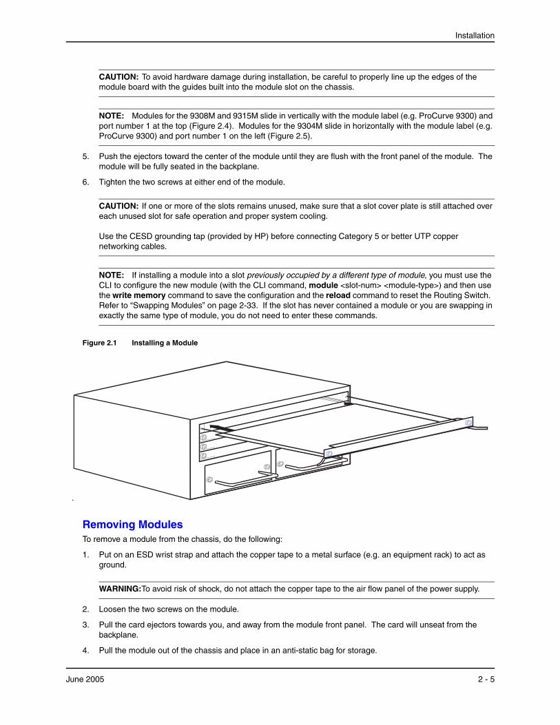
Installation
CAUTION: To avoid hardware damage during installation, be careful to properly line up the edges of the module board with the guides built into the module slot on the chassis.
NOTE: Modules for the 9308M and 9315M slide in vertically with the module label (e.g. ProCurve 9300) and port number 1 at the top (Figure 2.4). Modules for the 9304M slide in horizontally with the module label (e.g. ProCurve 9300) and port number 1 on the left (Figure 2.5).
5. Push the ejectors toward the center of the module until they are flush with the front panel of the module. The module will be fully seated in the backplane.
6. Tighten the two screws at either end of the module.
CAUTION: If one or more of the slots remains unused, make sure that a slot cover plate is still attached over each unused slot for safe operation and proper system cooling. Use the CESD grounding tap (provided by HP) before connecting Category 5 or better UTP copper networking cables.
NOTE: If installing a module into a slot previously occupied by a different type of module, you must use the CLI to configure the new module (with the CLI command, module <slot-num> <module-type>) and then use the write memory command to save the configuration and the reload command to reset the Routing Switch. Refer to “Swapping Modules” on page 2-33. If the slot has never contained a module or you are swapping in exactly the same type of module, you do not need to enter these commands.
Figure 2.1 Installing a Module
Removing ModulesTo remove a module from the chassis, do the following:
1. Put on an ESD wrist strap and attach the copper tape to a metal surface (e.g. an equipment rack) to act as ground.
WARNING:To avoid risk of shock, do not attach the copper tape to the air flow panel of the power supply.
2. Loosen the two screws on the module.
3. Pull the card ejectors towards you, and away from the module front panel. The card will unseat from the backplane.
4. Pull the module out of the chassis and place in an anti-static bag for storage.
June 2005 2 - 5

Installation and Basic Configuration Guide for ProCurve 9300 Series Routing Switches
5. Cover the slot with the blank face plate that shipped with the chassis.
CAUTION: If you remove a module and do not replace it, cover the slot opening with one of the blank plates you received with the Routing Switch to provide additional safety and airflow for the system.
NOTE: Modules can be installed and removed when the unit is powered on (hot swap). There is no need to power the system down. You do not need to change the slot’s configuration unless you plan to insert a different type of module. Refer to “Swapping Modules” on page 2-33.
Installing and Removing (Optional) Mini-GBICsThis section provides installation information for the following HP ProCurve Mini-GBIC products:
• J4858A ProCurve Gigabit-SX Mini-GBIC or J4858B ProCurve Gigabit-SX Mini-GBIC with an LC connector: Supports multi-mode fiber; LC connector.
• J4859A ProCurve Gigabit-LX Mini-GBIC or J4859B ProCurve Gigabit-LX Mini-GBIC with an LC connector: Supports single-mode and multi-mode fiber; LC connector. Multi-Mode LX supports a shorter distance than single-mode LX.
• J4860A ProCurve Gigabit LH Mini-GBIC or J4860B ProCurve Gigabit-LH with an LC connector: Supports single-mode fiber; LC connector.
• J8177B ProCurve 1000Base-T Mini-GBIC with an RJ-45 connector.
You can install any combination of the above mini-GBICs in the ProCurve 9300 mini-GBIC modules. See “Cable Length” on page 2-21 for cabling information.
Software Version and Management Module RequirementAll the ProCurve mini-GBICs listed above are supported on the current version of boot code (07.06.05) and software (07.8.00a). However, the J8177B 1000Base-T mini-GBIC is supported only in EP modules.
Installing or Removing a Mini-GBICTo install a mini-GBIC:
1. Put on an electrostatic discharge (ESD) wrist strap and attach the copper tape to a metal surface (such as an equipment rack) to act as ground.
2. Remove the mini-GBIC from its protective packaging.
3. Gently insert the mini-GBIC into the slot on the front panel of the module until the mini-GBIC clicks into place. The mini-GBICs are keyed to prevent incorrect insertion. A tab on the bottom of the mini-GBIC locks the mini-GBIC to the front panel of the module.
4. Remove the protective covering from the port connectors and store the covering for future use.
5. Insert the interface cable.
To remove a mini-GBIC:
1. Put on an ESD wrist strap and attach the copper tape to a metal surface (such as an equipment rack) to act as ground.
2. Disconnect the interface cable from the mini-GBIC.
3. Insert the protective covering into the port connectors.
4. Do one of the following:
• If the mini-GBIC has a bail, swing the bail out, and then gently pull on it to slide the mini-GBIC out of the module.
2 - 6 June 2005
Installation
• If the mini-GBIC has a movable collar, push the collar in towards the front panel of the routing switch and and then gently pull on the mini-GBIC to slide it out of the module.
5. Pull the mini-GBIC out of the module.
6. Store the mini-GBIC in a safe, static-free place.
Installation Notes1000Base-SX Ports
The 1000Base-SX mini-GBIC ports operate in full-duplex mode and support multi-mode fiber cabling through LC connectors. A 1000Base-SX mini-GBIC port must be connected to another 1000Base-SX port. Connection to a 1000Base-LX port or a 1000Base-LH port is not supported.
1000Base-LX Ports
The 1000Base-LX mini-GBIC ports operate in full-duplex mode and support both single-mode fiber (SMF) and multi-mode fiber (MMF) cabling through LC connectors. A 1000Base-LX mini-GBIC port must be connected to another 1000Base-LX port. Connection to a 1000Base-SX port or a 1000Base-LH port is not supported.
1000Base-LH Ports
The 1000Base-LH mini-GBIC ports operate in full-duplex mode and supports single-mode fiber (SMF) cabling through LC connectors. A 1000Base-LH mini-GBIC port must be connected to another 1000Base-LH port. Connection to a 1000Base-LX or 1000Base-SX mini-GBIC port is not supported.
Software Support for Mini-GBIC PortsHewlett-Packard offers and supports only mini-GBICs that include an HP label (product numbers J4858A/B, J4859A/B, J4860A/B, and J8177B) for use with ProCurve 9300 Mini-GBIC Module. Use of other brands of mini-GBICs or the use of HP mini-GBICs in non-HP devices is not supported.
Removing and Installing XENPAK OpticsYou can remove a XENPAK optic from a 10 Gigabit Ethernet module and replace it with a new one while the HP device is powered on and running.
Before performing either of these tasks, have the following on hand:
• An electrostatic discharge (ESD) wrist strap
WARNING: For safety reasons, the ESD wrist strap provided with your product contains a series limiting resistor. If a replacement ESD strap is used, make certain that it contains a series limiting resistor with at least 1MOhm of resistance. Also, make certain the strap is not connected to any internal part of your ProCurve chassis.
• The protective covering that you removed from the port connectors when you initially installed the XENPAK optic
• The new XENPAK optic (if you are installing one)
• A small flathead screwdriver
Removing a XENPAK OpticTo remove a XENPAK optic from a 10 Gigabit Ethernet module, do the following:
1. Put on the ESD wrist strap and attach the copper tape to a metal surface (such as an equipment rack) to act as ground.
2. Disconnect the two fiber cable connectors from the port connectors.
3. Insert the protective covering into the port connectors.
June 2005 2 - 7
Installation and Basic Configuration Guide for ProCurve 9300 Series Routing Switches
4. Using the flathead screwdriver if necessary, loosen the two thumbscrews on the ends of the XENPAK optic.
5. Pull the XENPAK optic out of the port, and place it in an anti-static bag for storage if desired.
Installing a XENPAK OpticTo install a XENPAK optic in a 10 Gigabit Ethernet module, do the following:
1. Put on the ESD wrist strap and attach the copper tape to a metal surface (such as an equipment rack) to act as ground.
2. Remove the new XENPAK optic from its protective packaging.
3. Gently insert the the XENPAK optic into the module until it clicks into place. The XENPAK optics are keyed to prevent incorrect insertion.
Secure the XENPAK optic by tightening the two thumb-screws. If desired, you can further tighten the thumb-screws using the flathead screwdriver.
Software Support for XENPAK OpticsHewlett-Packard offers and supports only XENPAK optics that include an HP label (product number J8173A, J8175A, or J8176A) for use with the J8174A HP ProCurve 9300 XENPAK module. Use of other brands of optics or the use of HP-labeled XENPAK optics in non-HP device is not supported.
Cleaning the Fiber Optic ConnectorsTo avoid problems with the connection between the fiber-optic module connectors and the fiber cable connectors, HP strongly recommends cleaning both connectors each time you disconnect and reconnect them. In particular, dust can accumulate in the connectors and cause problems such as reducing the optic launch power.
To clean the fiber cable connectors, HP recommends using a fiber-optic reel-type cleaner. You can purchase this type of cleaner from the following Web site:
http://www.fisfiber.com/fisfiber.com/Home_Page.asp
To clean the fiber-optic module connectors, HP recommends using a product that dispenses dust-free air, such as Micro-Blast. You can purchase such a product from the following Web site:
http://www.microcare.com/product/solvents/PS-50.html.
When cleaning a fiber-optic module connector, do not use unfiltered air from an air compressor, cotton swabs, or other types of swab applicators. These types of products may leave lint or dust in the connector.
Also, when not using a fiber-optic module connector, make sure to keep the protective covering on.
Installing (or Removing) Redundant Power Supplies
Determining Power Supply StatusIf you are replacing a power supply that has failed and you are not sure which supply has failed, enter the following command at any CLI command prompt:
ProCurveRS# show chassis
2 - 8 June 2005
Installation
This command displays status information for the fans and the power supplies. The power supplies are numbered in the display. The power supply numbers correspond to the following positions. These positions assume you are facing the front of the chassis, not the rear.
Table 2.1: Power Supply Positions in HP ProCurve 9300 Devices
Product Power Supply 1 Position
Power Supply 2 Position
Power Supply 3 Position
Power Supply 4 Position
9304M left side right side n/a n/a
9308M bottom second from bottom
second from top top
9315M left side second left second right right side
Installing Power SuppliesTo install a power supply in the chassis, do the following:
CAUTION: Install the J4147A Power Supply only in the 9308M (J4138A) and 9304M (J4139A) Routing Switch chassis. Install the J4875A Power Supply only in the 9315M (J4875A) Routing Switch. The J4147A and J4875A Power Supplies are not interchangeable.
CAUTION: Power supplies are hot swappable but they should be disconnected from AC power before being installed or removed. That is, the Routing Switch can be running while a power supply is being installed or removed, but the power supply itself should not be connected to a power source. Otherwise, damage to the power supply or the Routing Switch could result.
1. Use a screwdriver to remove the blank power supply face plate. This will expose the empty power supply slot.
2. Remove the power supply from its packaging; or, if the power supply is connected to a power source, remove the power cable.
3. Holding the bar on the front panel of the power supply, insert the power supply into the empty power supply slot using the module guides provided on either side of the compartment.
CAUTION: Carefully follow the mechanical guides on each side of the power supply slot and make sure the power supply is properly inserted in the guides. Never insert the power supply upside down.
4. Continue to slide the power supply towards the back of the chassis until the two metal rods and the connector make contact with the back connector. Then push the power supply until the front panel of the power supply is flush with the rest of the chassis.
5. Use a screwdriver to tighten the two screws on either side of the power supply.
6. Connect the power cord to the front of the power supply.
7. Connect the power plug into an outlet.
June 2005 2 - 9

Installation and Basic Configuration Guide for ProCurve 9300 Series Routing Switches
Figure 2.2 Installing a Power Supply
Removing Power SuppliesTo remove a power supply module from the chassis, do the following:
CAUTION: Power supplies are hot swappable but they should be disconnected from AC power before being installed or removed. That is, the Routing Switch can be running while a power supply is being installed or removed, but the power supply itself should not be connected to a power source. Otherwise, damage to the power supply or the Routing Switch could result.
1. Unplug the power supply AC power cord from the outlet.
2. Disconnect the power cord from the power supply.
3. Use a screwdriver to loosen the screws on either side of the power supply.
4. Holding the bar on the front panel of the power supply, pull outward, disconnecting the power supply from the backplane.
5. Continue to pull the power supply until it is removed from the chassis.
6. Place the power supply in an anti-static bag for storage.
7. Cover the power supply slot with the blank power supply cover that came with the device.
8. Use a screwdriver to tighten the screws.
2 - 10 June 2005
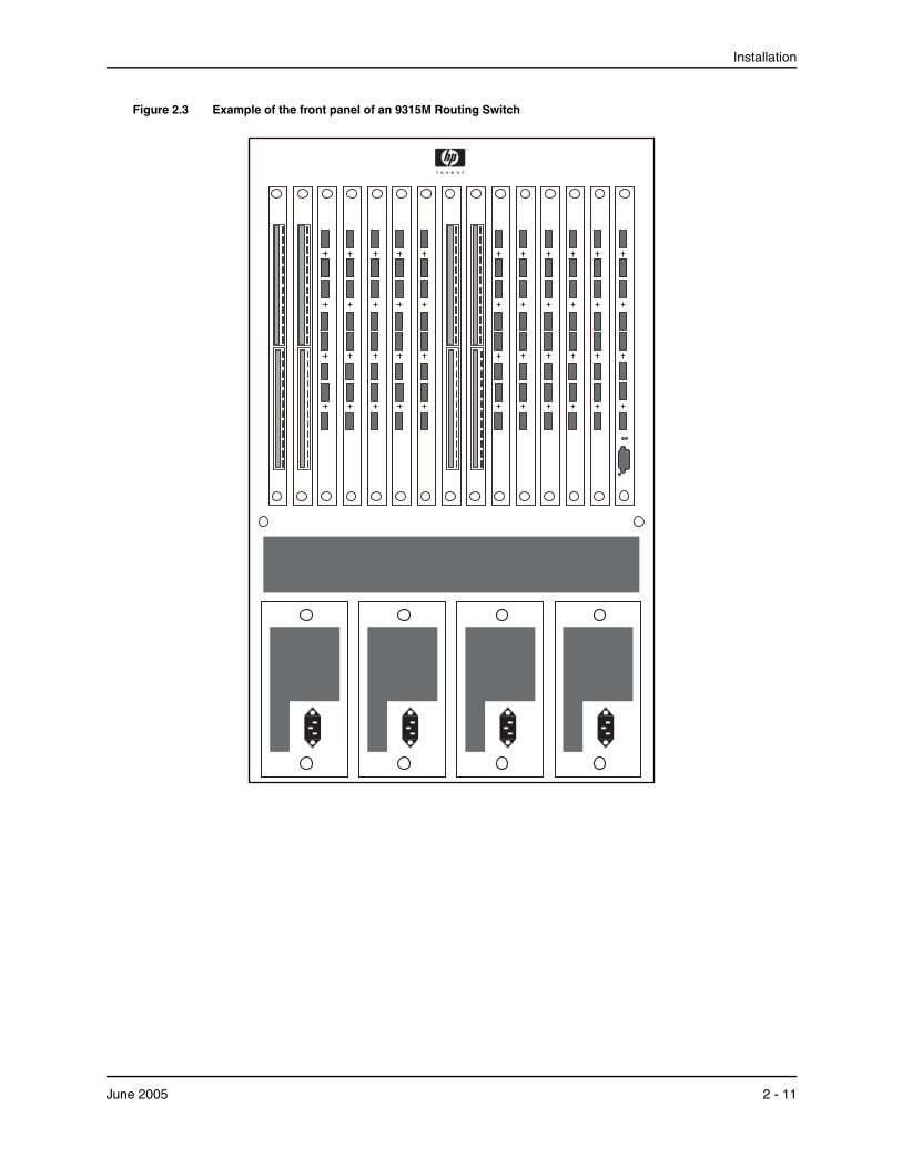
Installation
Figure 2.3 Example of the front panel of an 9315M Routing Switch
June 2005 2 - 11
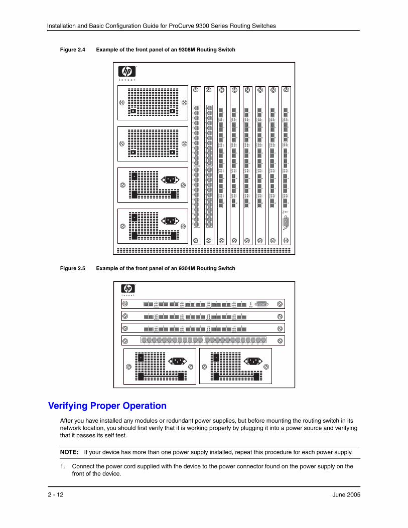
Installation and Basic Configuration Guide for ProCurve 9300 Series Routing Switches
Figure 2.4 Example of the front panel of an 9308M Routing Switch
35
42
Link
Activity
61
78
Link
Activity
Link
Activity
Link
Activity
1 2 3 4 5 6 7 8 9 10 11 1213 14 15 16 17 18 19 20 21 22 23 24
Link
Activity
Link
Activity
Link
Activity
Link
Activity
35
42
61
78
1 2 3 4 5 6 7 8 9 10 11 1213 14 15 16 17 18 19 20 21 22 23 24
35
42
Link
Activity
61
78
Link
Activity
Link
Activity
Link
Activity
35
42
Link
Activity
61
78
Link
Activity
Link
Activity
Link
Activity
35
42
Link
Activity
61
78
Link
Activity
Link
Activity
Link
Activity
Link
Activity
13
67
85
42
Pw
r
Link
Activity
Link
Activity
Link
Activity
Figure 2.5 Example of the front panel of an 9304M Routing Switch
Link
Activity
1 3 6 7 8542
Pwr
Link
Activity
Link
Activity
Link
Activity
3 542Link
Activity
61 7 8Link
Activity
Link
Activity
Link
Activity
1 2 3 4 5 6 7 8 9 10 11 12 13 14 15 16 17 18 19 20 21 22 23 24
3 542Link
Activity
61 7 8Link
Activity
Link
Activity
Link
Activity
Verifying Proper OperationAfter you have installed any modules or redundant power supplies, but before mounting the routing switch in its network location, you should first verify that it is working properly by plugging it into a power source and verifying that it passes its self test.
NOTE: If your device has more than one power supply installed, repeat this procedure for each power supply.
1. Connect the power cord supplied with the device to the power connector found on the power supply on the front of the device.
2 - 12 June 2005
Installation
2. Insert the other end into a properly grounded electrical outlet.
NOTE: The devices do not have power switches. They are powered on when the power cord is connected to the device and to a power source. If your installation requires a different power cord than that supplied with the device, be sure to obtain a power cord displaying the mark of the safety agency that defines the regulations for power cords in your country. The mark is your assurance that the power cord can be used safely with the device.
3. Verify proper operation by observing the LEDs. Make sure the LED on each power supply is a solid green. Also make sure that some of the port LEDs on each module momentarily light up. The LEDs indicate that the device is performing diagnostics. After the diagnostics are complete, the LEDs will be dark except for the ones that are attached by cables to other devices. If the links on these cables are good and the connected device is powered on, the link LEDs will light.
NOTE: If all of the LEDs on a module do not light up during the diagnostics, this does not indicate an error. Only some of the LEDs are lighted during the diagnostics.
For more details on specific LED conditions after system start-up, refer to the Quick Start Guide.
Attaching a PC or TerminalTo assign an IP address, you must have access to the Command Line Interface (CLI). The CLI is a text-based interface that can be accessed through a direct serial connection to the device and through Telnet connections. The CLI is described in detail in the Command Line Interface Reference for ProCurve 9300/9400 Series Routing Switches.
You need to assign a permanent IP address using the CLI. You can access the CLI by attaching a serial cable to the Console port. After you assign an IP address, you can access the system through Telnet or the Web management interface.
Attaching a PC or Terminal Using a Serial PortTo attach a management station using the serial port:
1. Connect a PC or terminal to the serial port of the system via the (serial) console cable. The serial port is a male DB-9 connector. Generally, a PC port will require a cable with a female DB-9 connector. Terminal connections will vary, requiring either a DB-9 or DB-25 connector, male or female.
A console cable is provided with your Routing Switch. Cable pin-outs and signalling for the serial port are shown in Figure 2.6 and Figure 2.7.
2. If you are using a PC for a terminal, run a terminal emulation program on the PC.
3. Set the terminal or PC terminal emulation program to the parameters shown below:
• Baud: 9600 bps
• Data bits: 8
• Parity: None
• Stop bits: 1
• Flow control: None
Attaching a PC or Terminal Using a Direct LAN ConnectionTo attach a management station using a direct LAN connection:
NOTE: Use this procedure if you are unable to make the serial connection described above.
June 2005 2 - 13

Installation and Basic Configuration Guide for ProCurve 9300 Series Routing Switches
Important! Cable Grounding Instructions
HP provides a cable-grounding kit for use with 9304M/9308M/9315M chassis modules designed for UTP copper networking cable connections. Use this grounding kit to help prevent ESD damage to your Routing Switch components when connecting cables to the modules.
CAUTION: Before connecting Category 5 or better UTP copper networking cables to a chassis module on the 9300 series, use the CESD grounding tap (shipped with the 9304M/9308M/9315M and with chassis modules designed for UTP copper networking cables). See the Cable Grounding Instructions included with the CESD grounding tap. If you did not receive a CESD grounding tap kit (HP part number 5064-9974) with the above HP products, you can request one without charge from your HP Customer Care Center (CCC). To contact the CCC for your area, see the support and warranty booklet (Support is as Close as the World Wide Web!) shipped with your HP product. CCCs are also listed in the HP ProCurve Networking Service and Support Guide available at http://www.procurve.com. (Click on Technical Support, then Support Services.)
1. Directly connect the LAN port on a Telnet-capable terminal device such as a laptop or desktop PC to port 1 in slot 1.
2. Configure the terminal device with an IP address and subnet mask that assigns the terminal to the same subnet as the Routing Switch's IP address for port 1, slot 1.
3. From the DOS prompt, enter telnet <ip-addr> to access the Routing Switch CLI, where <ip-addr> is the IP address for the Routing Switch port.
When you establish the serial connection to the device, press Enter to display the CLI prompt for your Routing Switch. For example:
HP9304>
HP9308>
HP9315>
NOTE: For simplicity, CLI examples for the routing switches generally show the command prompt "HP9300". This command prompt represents either the 9300 series unless otherwise noted.
If you see one of these prompts, you are now connected to the system and can proceed to “Assigning a Permanent Password” on page 2-15.
You can customize the prompt by changing the system name. See “Entering System Administration Information” on page 6-3.
If you do not see one of these prompts:
1. Make sure the cable is securely connected to your PC and to the HP device.
2. Check the settings in your terminal emulation program. In addition to the session settings listed above, make sure the terminal emulation session is running on the same serial port you attached to the HP device.
The EIA/TIA 232 serial communication port serves as a connection point for management by a PC or SNMP workstation. ProCurve Routing Switches come with a standard male DB-9 connector, shown in Figure 2.6.
2 - 14 June 2005
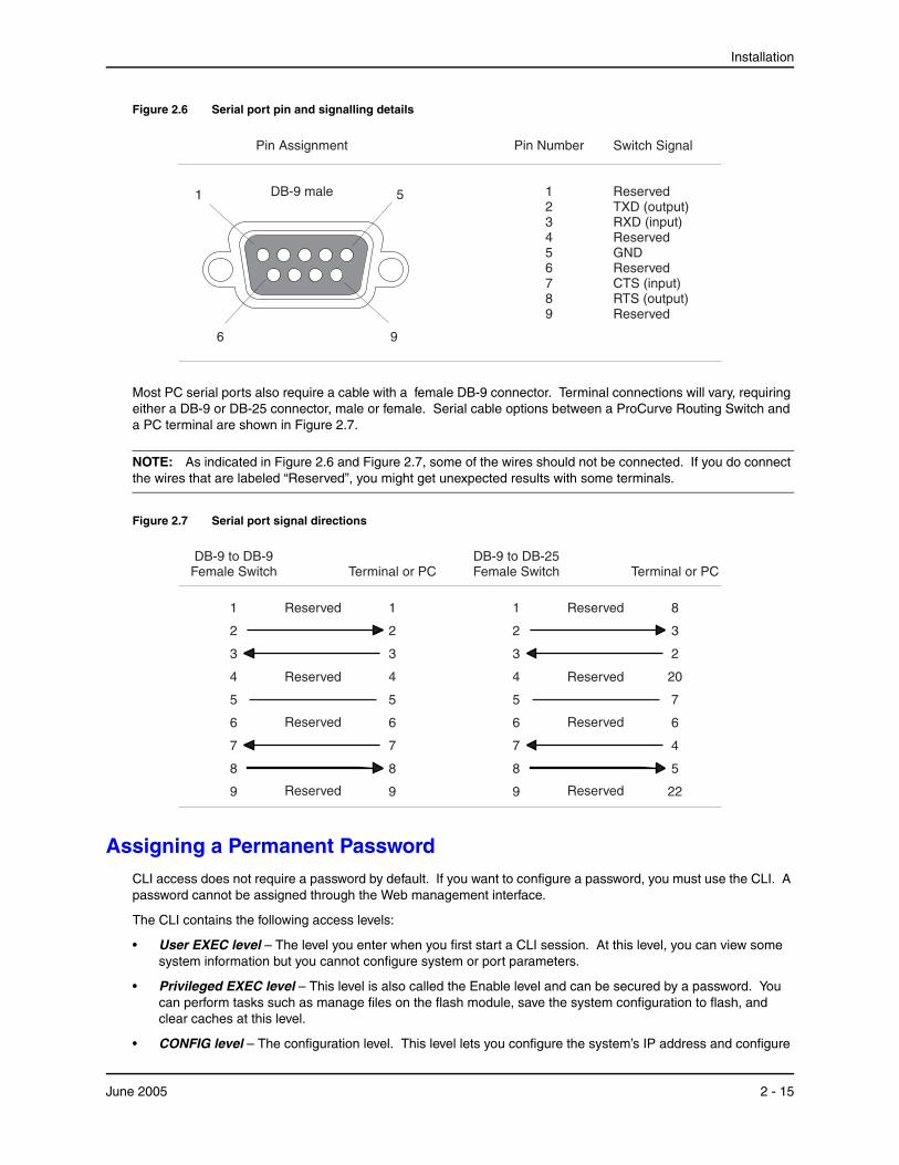
Installation
Figure 2.6 Serial port pin and signalling details
1 5
96
Pin Assignment
DB-9 male
Pin Number
123456789
Switch Signal
ReservedTXD (output)RXD (input)
GND
CTS (input)RTS (output)
Reserved
Reserved
Reserved
Most PC serial ports also require a cable with a female DB-9 connector. Terminal connections will vary, requiring either a DB-9 or DB-25 connector, male or female. Serial cable options between a ProCurve Routing Switch and a PC terminal are shown in Figure 2.7.
NOTE: As indicated in Figure 2.6 and Figure 2.7, some of the wires should not be connected. If you do connect the wires that are labeled “Reserved”, you might get unexpected results with some terminals.
Figure 2.7 Serial port signal directions
1
2
3
4
5
6
7
8
9
1
2
3
4
5
6
7
8
9
Reserved
DB-9 to DB-9Female Switch
Reserved
Reserved
Reserved
Terminal or PC
1
2
3
4
5
6
7
8
9
8
3
2
20
7
6
4
5
22
Reserved
DB-9 to DB-25Female Switch
Reserved
Reserved
Reserved
Terminal or PC
Assigning a Permanent PasswordCLI access does not require a password by default. If you want to configure a password, you must use the CLI. A password cannot be assigned through the Web management interface.
The CLI contains the following access levels:
• User EXEC level – The level you enter when you first start a CLI session. At this level, you can view some system information but you cannot configure system or port parameters.
• Privileged EXEC level – This level is also called the Enable level and can be secured by a password. You can perform tasks such as manage files on the flash module, save the system configuration to flash, and clear caches at this level.
• CONFIG level – The configuration level. This level lets you configure the system’s IP address and configure
June 2005 2 - 15

Installation and Basic Configuration Guide for ProCurve 9300 Series Routing Switches
switching and routing features. To access the CONFIG mode, you must already be logged into the Privileged level of the EXEC mode.
By default, there are no CLI passwords. To secure CLI access, you must assign passwords.
NOTE: You must use the CLI to assign a password. You cannot assign a password using the Web management interface or an SNMP network management application.
You can set the following levels of Enable passwords:
• Super User – Allows complete read-and-write access to the system. This is generally for system administrators and is the only password level that allows you to configure passwords. You must set a super user password before you can set other types of passwords.
• Port Configuration – Allows read-and-write access for specific ports but not for global (system-wide) parameters.
• Read Only – Allows access to the Privileged EXEC mode and CONFIG mode but only with read access.
How To Assign a PasswordWhen you first connect to the CLI, you are at the User EXEC level of the CLI. This is the first level of the CLI. The next level is the Privileged EXEC level. You need to get to the global CONFIG level of the CONFIG command structure to assign a permanent password.
To reach the global CONFIG level and assign passwords, use the following steps:
1. At the opening prompt, enter the following command to go from the User EXEC level to the Privileged EXEC level:
ProCurveRS> enable
2. Access the configuration level of the CLI by entering the following command:
ProCurveRS# configure terminal Privileged EXEC Level
ProCurveRS(config)# Global CONFIG Level
3. To set the super-user password:
ProCurveRS(config)# enable super-user-password <string>
NOTE: You must set a super-user password before you can set other types of passwords.
4. To set the port-configuration and read-only passwords:
ProCurveRS(config)# enable read-only-password <string>
ProCurveRS(config)# enable port-config-password <string>
How to Recover From a Lost Password
Recovery from a lost password requires direct access to the serial port and a system reset of the device.
NOTE: You can perform this procedure only from the CLI.
To recover from a lost password:
1. Start a CLI session over the serial interface to the device.
2. Reboot the device.
3. While the system is booting, before the initial system prompt appears, enter b to enter the boot monitor mode.
4. Enter no password at the prompt. This command cannot be abbreviated. This command will cause the device to bypass the system password check.
2 - 16 June 2005
Installation
5. Enter boot system flash primary.
6. After the console prompt reappears, assign a new password.
Assign a Permanent IP AddressBefore attaching a ProCurve Routing Switch to your network, you must assign an interface IP address to the subnet on which the Routing Switch will be located. For subsequent addresses, you also can use the CLI through Telnet or use the Web management interface.
Using a serial connection is the recommended method for assigning the first IP address on a Routing Switch. (You also can use Telnet with a direct, terminal-to-device LAN connection if necessary—see “Attaching a PC or Terminal Using a Direct LAN Connection” on page 2-13.)
On the 9300 series, you can configure up to 24 IP interfaces on each port, virtual interface, and loopback interface. See “Displaying and Modifying System Parameter Default Settings” on page 6-43.
The following procedure shows how to add an IP address and mask to a Routing Switch port.
1. At the opening CLI prompt, enter enable.
ProCurveRS> enable
2. If you are prompted for the password you created in “Assigning a Permanent Password” on page 2-15, enter the password.
CAUTION: Use Step 3 only for new systems. If you enter this command on a system you have already configured, the command erases the configuration. If you accidentally do erase the configuration on a configured system, enter the write memory command to save the running configuration to the startup-config file.
3. For new systems only, enter the following command at the Privileged EXEC level prompt (for example, ProCurveRS#), then press Enter. This command erases the factory test configuration if still present:
ProCurveRS# erase startup-config
4. Access the configuration level of the CLI by entering the following command:
ProCurveRS# configure terminal Privileged EXEC Level
ProCurveRS(config)# Global CONFIG Level
5. Set the IP and mask addresses.
ProCurveRS(config)# int e 1/5
ProCurveRS(config-if-1/5)# ip address 192.22.3.44 255.255.255.0
NOTE: You can use the syntax, ip address <ip-addr> /<mask-bits> if you know the subnet mask length. In the above example, you could enter ip address 192.22.3.44/24.
Syntax: enable [<password>]
Syntax: configure terminal
Syntax: [no] ip address <ip-addr> <ip-mask> [secondary]
or
Syntax: [no] ip address <ip-addr>/<mask-bits> [secondary]
Use the secondary parameter if you have already configured an IP address within the same subnet on the interface.
June 2005 2 - 17

Installation and Basic Configuration Guide for ProCurve 9300 Series Routing Switches
Mounting the Device The ProCurve Routing Switches can be installed on a desktop or in a rack.
WARNING: The 9304M chassis exceeds 40 lbs. (18 kg), or 47.7 lbs.(21.6 kg) when fully populated with modules and power supplies. Also, the 9308M chassis exceeds 55 lbs. (24.9 kg) or 69.1 lbs. (31.3 kg) when fully populated with modules and power supplies. TWO OR MORE PEOPLE ARE REQUIRED WHEN LIFTING, HANDLING, OR MOUNTING THESE ROUTING SWITCHES.
WARNING: The 9315M chassis exceeds 80 lbs (35 kg.) without modules and power supplies installed. To avoid personal injury, reduce weight of chassis by removing all modules and power supplies from chassis prior to lifting or moving. TWO OR MORE PEOPLE ARE REQUIRED WHEN LIFTING, HANDLING, OR MOUNTING THIS ROUTING SWITCH.
WARNING: Do not lift the 15-slot chassis using the lifting handles unless the chassis is empty. TO REDUCE WEIGHT, REMOVE THE POWER SUPPLIES AND INTERFACE MODULES BEFORE LIFTING THE CHASSIS.
WARNING: Do not use the extraction handles on the power supply units to lift or carry the Routing Switch. The power supply extraction handles are not intended to support the weight of the system and must never be used to lift or move the chassis.
WARNING: Make sure the rack or cabinet housing the Routing Switch is adequately secured to prevent it from becoming unstable and/or falling over.
WARNING: To increase rack stability, mount the devices you install in a rack or cabinet as low as possible, with the heaviest device at the bottom and progressively lighter devices installed above.
Desktop Installation1. Set the device on a flat desktop, table, or shelf. Use a sturdy surface in an uncluttered area. You may want
to secure the networking cables and power cord to the table legs or other part of the surface structure to help prevent people from tripping over them.
2. Make sure that adequate ventilation is provided for the system—a minimum of three inches (3") clearance is recommended on all sides.
NOTE: Make sure the air flow is unrestricted around the front, sides, and back of the Routing Switch.
3. Proceed to “Connecting Power to the Device” on page 2-20.
2 - 18 June 2005
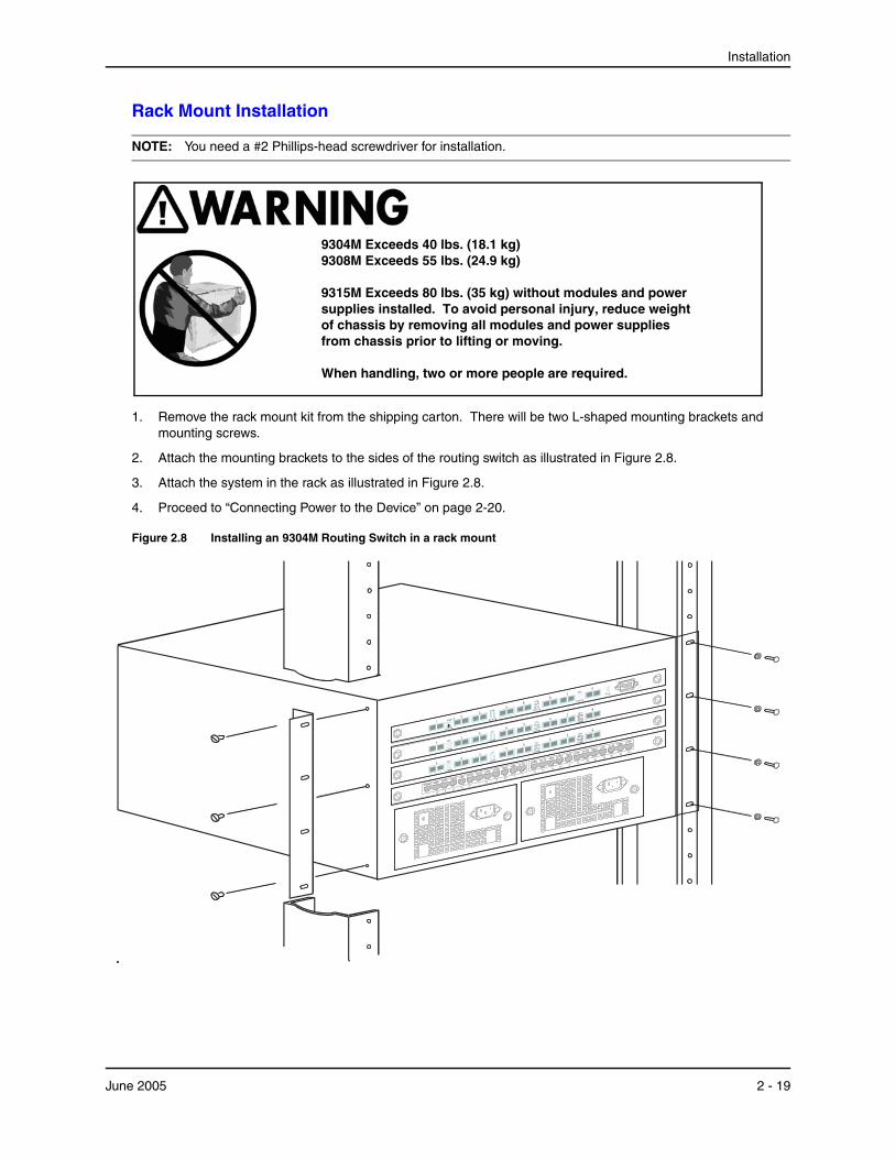
Installation
Rack Mount Installation
NOTE: You need a #2 Phillips-head screwdriver for installation.
9304M Exceeds 40 lbs. (18.1 kg)9308M Exceeds 55 lbs. (24.9 kg)
9315M Exceeds 80 lbs. (35 kg) without modules and power supplies installed. To avoid personal injury, reduce weight of chassis by removing all modules and power supplies from chassis prior to lifting or moving.
When handling, two or more people are required.
1. Remove the rack mount kit from the shipping carton. There will be two L-shaped mounting brackets and mounting screws.
2. Attach the mounting brackets to the sides of the routing switch as illustrated in Figure 2.8.
3. Attach the system in the rack as illustrated in Figure 2.8.
4. Proceed to “Connecting Power to the Device” on page 2-20.
Figure 2.8 Installing an 9304M Routing Switch in a rack mount
June 2005 2 - 19
Installation and Basic Configuration Guide for ProCurve 9300 Series Routing Switches
Connecting Power to the DeviceWith physical installation of the Routing Switch complete, it is now time to power up the system and connect the network devices.
CAUTION:
• There is no separate on/off power switch for the device. The device is powered on when the power cord is connected to a power supply and to a power source. To turn the system off, simply unplug the power cord(s).
• The power sockets should be installed near the device and should be easily accessible.
• If your installation requires a different power cord than the one supplied with the device, be sure to use a power cord displaying the mark of the safety agency that defines the regulations for power cords in your country. The mark is your assurance that the power cord can be used safely with the system.
• For additional warnings and cautions, refer to the “Installation Precautions” on page 2-3.
NOTE: When you power on a Routing Switch that requires multiple power supplies, make sure you apply power to all the supplies (or at least the minimum number of supplies required for your configuration) at the same time. Otherwise, the device either will not boot at all, or will boot and then repeatedly display a warning message stating that you need to add more power supplies.
1. Ensure that all modules and power supplies are properly inserted, and that no module slots or power supply slots are uncovered.
WARNING: Electrical shock hazard. Never allow any part of your body to be inside the chassis when the device is connected to a power source or to the network.
2. Remove the power cord from the shipping package.
3. Attach the AC power cord to the AC connector on the front panel of the Routing Switch. If more than one power supply is installed, attach a power cord for each power supply.
4. Insert the power cord plug(s) into the appropriate outlet(s).
Connecting Network DevicesProCurve Routing Switches can support connections to other vendors’ Routing Switches and hubs as well as to other ProCurve Routing Switches and hubs.
Important! Cable Grounding Instructions
HP provides a cable-grounding kit for use with 9300 series chassis modules designed for UTP copper networking cable connections. Use this grounding kit to help prevent ESD damage to your Routing Switch components when connecting cables to the modules.
CAUTION: Before connecting Category 5 or better UTP copper networking cables to a chassis module on the 9304M or 9308M, use the CESD grounding tap (shipped with the 9300 series and with chassis modules designed for UTP copper networking cables). See the Cable Grounding Instructions included with the CESD grounding tap. If you did not receive a CESD grounding tap kit (HP part number 5064-9974) with the above HP products, you can request one without charge from your HP Customer Care Center (CCC). To contact the CCC for your area, see the support and warranty booklet (Support is as Close as the World Wide Web!) shipped with your HP product. CCCs are also listed in the HP ProCurve Networking Service and Support Guide available at http://www.hp.com/go/hpprocurve. (Click on Technical Support, then Support Services.)
2 - 20 June 2005
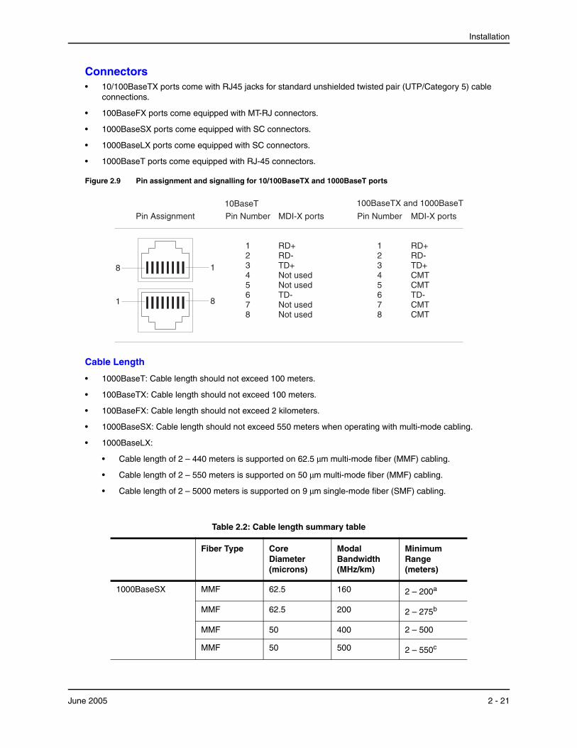
Installation
Connectors• 10/100BaseTX ports come with RJ45 jacks for standard unshielded twisted pair (UTP/Category 5) cable
connections.
• 100BaseFX ports come equipped with MT-RJ connectors.
• 1000BaseSX ports come equipped with SC connectors.
• 1000BaseLX ports come equipped with SC connectors.
• 1000BaseT ports come equipped with RJ-45 connectors.
Figure 2.9 Pin assignment and signalling for 10/100BaseTX and 1000BaseT ports
Pin Assignment Pin Number
12345678
Pin Number
12345678
8 1
1 8
MDI-X ports
RD+RD-TD+Not used
TD-Not used
Not usedNot used
100BaseTX and 1000BaseT10BaseT
MDI-X ports
RD+RD-TD+CMT
TD-CMT
CMTCMT
Cable Length
• 1000BaseT: Cable length should not exceed 100 meters.
• 100BaseTX: Cable length should not exceed 100 meters.
• 100BaseFX: Cable length should not exceed 2 kilometers.
• 1000BaseSX: Cable length should not exceed 550 meters when operating with multi-mode cabling.
• 1000BaseLX:
• Cable length of 2 – 440 meters is supported on 62.5 μm multi-mode fiber (MMF) cabling.
• Cable length of 2 – 550 meters is supported on 50 μm multi-mode fiber (MMF) cabling.
• Cable length of 2 – 5000 meters is supported on 9 μm single-mode fiber (SMF) cabling.
Table 2.2: Cable length summary table
Fiber Type Core Diameter (microns)
Modal Bandwidth (MHz/km)
Minimum Range (meters)
1000BaseSX MMF 62.5 160 2 – 200a
MMF 62.5 200 2 – 275b
MMF 50 400 2 – 500
MMF 50 500 2 – 550c
June 2005 2 - 21

Installation and Basic Configuration Guide for ProCurve 9300 Series Routing Switches
NOTE: Cable installation and network configuration will affect overall transmission capability. The numbers provided above represent the accepted recommendations of the various standards. For network-specific recommendations, consult your local HP reseller or system engineer.
Connecting to Other Switches, Routing Switches, and Ethernet HubsFor connections to Ethernet hubs, a 10/100BaseTX or 1000BaseT switch, or another ProCurve Routing Switch, a crossover cable is required (Figure 2.10 or Figure 2.11). If the hub is equipped with an uplink port, it will require a straight-through cable instead of a crossover cable.
Figure 2.10 UTP crossover cable for 10/100BaseTX
1
2
3
4
5
6
7
8
1
2
3
4
5
6
7
8
1 8
UTP Crossover Cable10/100BaseTX
unused
unused
unused
unused
unused
unused
unused
unused
1000BaseLX MMF 62.5 500 2 – 550
MMF 50 400 2 – 550
MMF 50 500 2 – 550
SMF 9 n/a 2 – 5000
a. The TIA 568 building wiring standard specifies 160/500 MHz/km MMF (Multi-mode Fiber).
b. The international ISO/IEC 11801 building wiring standard specifies 200/500 MHz*km MMF.
c. The ANSI Fibre Channel specification specifies 500/500 MHz/km 50 micron MMF and 500/500 MHz*km fiber has been proposed for addition to ISO/IEC 11801.
Table 2.2: Cable length summary table
Fiber Type Core Diameter (microns)
Modal Bandwidth (MHz/km)
Minimum Range (meters)
2 - 22 June 2005
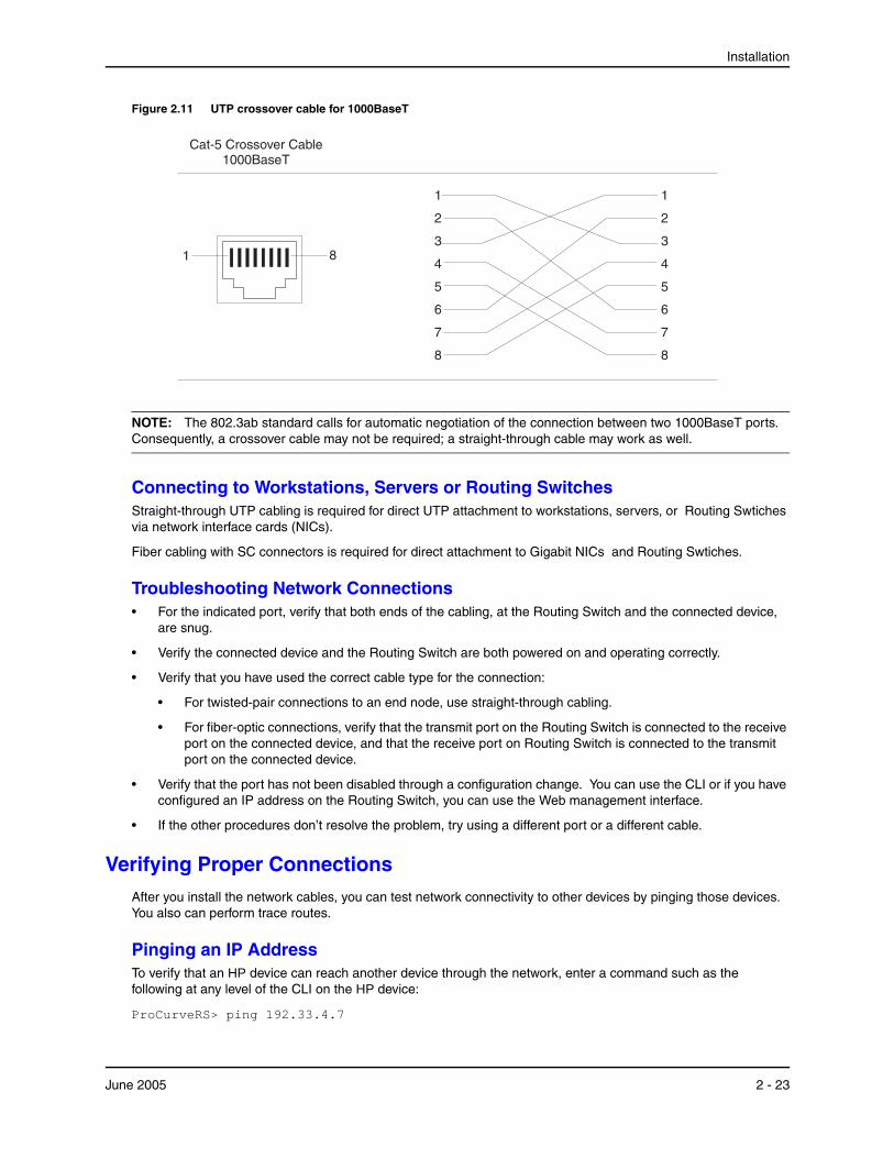
Installation
Figure 2.11 UTP crossover cable for 1000BaseT
1
2
3
4
5
6
7
8
1
2
3
4
5
6
7
8
1 8
Cat-5 Crossover Cable1000BaseT
NOTE: The 802.3ab standard calls for automatic negotiation of the connection between two 1000BaseT ports. Consequently, a crossover cable may not be required; a straight-through cable may work as well.
Connecting to Workstations, Servers or Routing SwitchesStraight-through UTP cabling is required for direct UTP attachment to workstations, servers, or Routing Swtiches via network interface cards (NICs).
Fiber cabling with SC connectors is required for direct attachment to Gigabit NICs and Routing Swtiches.
Troubleshooting Network Connections• For the indicated port, verify that both ends of the cabling, at the Routing Switch and the connected device,
are snug.
• Verify the connected device and the Routing Switch are both powered on and operating correctly.
• Verify that you have used the correct cable type for the connection:
• For twisted-pair connections to an end node, use straight-through cabling.
• For fiber-optic connections, verify that the transmit port on the Routing Switch is connected to the receive port on the connected device, and that the receive port on Routing Switch is connected to the transmit port on the connected device.
• Verify that the port has not been disabled through a configuration change. You can use the CLI or if you have configured an IP address on the Routing Switch, you can use the Web management interface.
• If the other procedures don’t resolve the problem, try using a different port or a different cable.
Verifying Proper ConnectionsAfter you install the network cables, you can test network connectivity to other devices by pinging those devices. You also can perform trace routes.
Pinging an IP AddressTo verify that an HP device can reach another device through the network, enter a command such as the following at any level of the CLI on the HP device:
ProCurveRS> ping 192.33.4.7
June 2005 2 - 23
Installation and Basic Configuration Guide for ProCurve 9300 Series Routing Switches
Syntax: ping <ip addr> | <hostname> [source <ip addr>] [count <num>] [timeout <msec>] [ttl <num>] [size <byte>] [quiet] [numeric] [no-fragment] [verify] [data <1-to-4 byte hex>] [brief]
See the Command Line Interface Reference for ProCurve 9300/9400 Series Routing Switches for information about its parameters.
NOTE: If you address the ping to the IP broadcast address, the device lists the first four responses to the ping.
Tracing a RouteTo determine the path through which an HP device can reach another device, enter a command such as the following at any level of the CLI on the HP device:
ProCurveRS> traceroute 192.33.4.7
Syntax: traceroute <host-ip-addr> [maxttl <value>] [minttl <value>] [numeric] [timeout <value>] [source-ip <ip addr>]
The CLI displays trace route information for each hop as soon as the information is received. Traceroute requests display all responses to a given TTL. In addition, if there are multiple equal-cost routes to the destination, the HP device displays up to three responses by default. See the Command Line Interface Reference for ProCurve 9300/9400 Series Routing Switches for information about the command syntax.
Managing the DeviceYou can manage an HP device using the following applications:
• Command Line Interface (CLI) – a text-based interface accessible through a direct serial connection or a Telnet session.
• Web management interface – A GUI-based management interface accessible through an HTTP (web browser) connection.
• SNMP network management application – An application such as HP ProCurve Manager for Routing Switches & Hubs or HP OpenView.
Logging on Through the CLIOnce an IP address is assigned to an interface on the ProCurve Routing Switch, you can access the CLI either through the direct serial connection to the device or through a local or remote Telnet session.
You can initiate a local Telnet or SNMP connection by attaching a straight-through RJ-45 cable to a port and specifying the assigned management station IP address.
The commands in the CLI are organized into the following levels:
• User EXEC level – Lets you display information and perform basic tasks such as pings and traceroutes.
• Privileged EXEC level – Lets you use the same commands as those at the User EXEC level plus configuration commands that do not require saving the changes to the system-config file.
• CONFIG level – Lets you make configuration changes to the device. To save the changes across reboots, you need to save them to the system-config file. The CONFIG level contains sub-levels for individual ports, for VLANs, for routing protocols, and other configuration areas.
NOTE: By default, any user who can open a serial or Telnet connection to the HP device can access all these CLI levels. To secure access, you can configure Enable passwords or local user accounts, and you can configure the device to use a RADIUS or TACACS/TACACS+ server for authentication. See the Security Guide for ProCurve 9300/9400 Series Routing Switches.
2 - 24 June 2005

Installation
On-Line Help
To display a list of available commands or command options, enter “?” or press Tab. If you have not entered part of a command at the command prompt, all the commands supported at the current CLI level are listed. If you enter part of a command, then enter “?” or press Tab, the CLI lists the options you can enter at this point in the command string.
If you enter an invalid command followed by ?, a message appears indicating the command was unrecognized. For example:
ProCurveRS(config)# rooter ip Unrecognized command
Command Completion
The CLI supports command completion, so you do not need to enter the entire name of a command or option. As long as you enter enough characters of the command or option name to avoid ambiguity with other commands or options, the CLI understands what you are typing.
Scroll Control
By default, the CLI uses a page mode to paginate displays that are longer than the number of rows in your terminal emulation window. For example, if you display a list of all the commands at the global CONFIG level but your terminal emulation window does not have enough rows to display them all at once, the page mode stops the display and lists your choices for continuing the display.
Here is an example:
aaa all-client appletalk arp boot
some lines omitted for brevity... ipx lock-address logging mac --More--, next page: Space, next line: Return key, quit: Control-c
The software provides the following scrolling options:
• Press the Space bar to display the next page (one screen at time).
• Press the Return or Enter key to display the next line (one line at a time).
• Press CTRL + C to cancel the display.
Line Editing Commands
The CLI supports the following line editing commands. To enter a line-editing command, use the CTRL-key combination for the command by pressing and holding the CTRL key, then pressing the letter associated with the command.
Table 2.3: CLI Line Editing Commands
Ctrl-Key Combination Description
Ctrl-A Moves to the first character on the command line.
Ctrl-B Moves the cursor back one character.
June 2005 2 - 25

Installation and Basic Configuration Guide for ProCurve 9300 Series Routing Switches
For a complete list of CLI commands and syntax information for each command, see the Command Line Interface Reference for ProCurve 9300/9400 Series Routing Switches.
Searching and Filtering Output from CLI CommandsYou can filter CLI output from show commands and at the --More-- prompt. You can search for individual characters, strings, or construct complex regular expressions to filter the output.
Searching and Filtering Output from show commands
You can filter output from show commands to display lines containing a specified string, lines that do not contain a specified string, or output starting with a line containing a specified string. The search string is a regular expression consisting of a single character or string of characters. You can use special characters to construct complex regular expressions. See “Using Special Characters in Regular Expressions” on page 2-29 for information on special characters used with regular expressions.
Displaying Lines Containing a Specified StringThe following command filters the output of the show interface command for port 3/11 so it displays only lines containing the word “Internet”. This command can be used to display the IP address of the interface.
ProCurveRS# show interface e 3/11 | include Internet Internet address is 192.168.1.11/24, MTU 1500 bytes, encapsulation ethernet
Syntax: <show-command> | include <regular-expression>
NOTE: The vertical bar ( | ) is part of the command.
Note that the regular expression specified as the search string is case sensitive. In the example above, a search string of “Internet” would match the line containing the IP address, but a search string of “internet” would not.
Ctrl-C Escapes and terminates command prompts and ongoing tasks (such as lengthy displays), and displays a fresh command prompt.
Ctrl-D Deletes the character at the cursor.
Ctrl-E Moves to the end of the current command line.
Ctrl-F Moves the cursor forward one character.
Ctrl-K Deletes all characters from the cursor to the end of the command line.
Ctrl-L; Ctrl-R Repeats the current command line on a new line.
Ctrl-N Enters the next command line in the history buffer.
Ctrl-P Enters the previous command line in the history buffer.
Ctrl-U; Ctrl-X Deletes all characters from the cursor to the beginning of the command line.
Ctrl-W Deletes the last word you typed.
Ctrl-Z Moves from any CONFIG level of the CLI to the Privileged EXEC level; at the Privileged EXEC level, moves to the User EXEC level.
Table 2.3: CLI Line Editing Commands (Continued)
Ctrl-Key Combination Description
2 - 26 June 2005
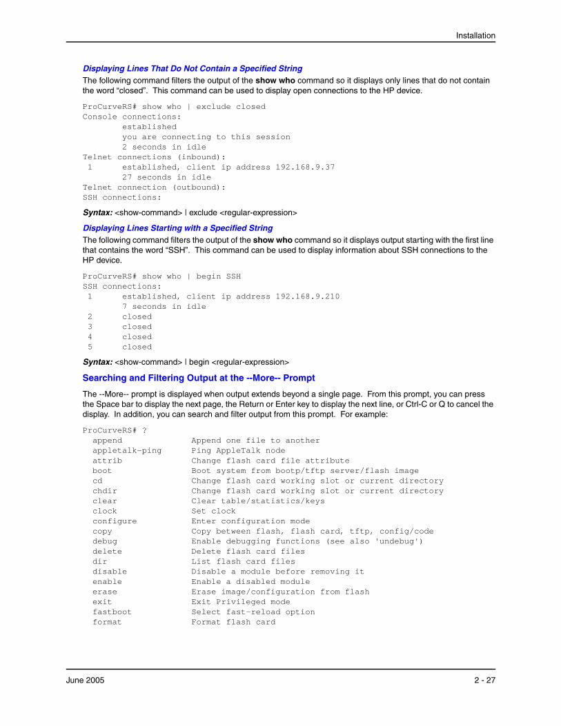
Installation
Displaying Lines That Do Not Contain a Specified StringThe following command filters the output of the show who command so it displays only lines that do not contain the word “closed”. This command can be used to display open connections to the HP device.
ProCurveRS# show who | exclude closed Console connections: established you are connecting to this session 2 seconds in idle Telnet connections (inbound): 1 established, client ip address 192.168.9.37 27 seconds in idle Telnet connection (outbound): SSH connections:
Syntax: <show-command> | exclude <regular-expression>
Displaying Lines Starting with a Specified StringThe following command filters the output of the show who command so it displays output starting with the first line that contains the word “SSH”. This command can be used to display information about SSH connections to the HP device.
ProCurveRS# show who | begin SSH SSH connections: 1 established, client ip address 192.168.9.210 7 seconds in idle 2 closed 3 closed 4 closed 5 closed
Syntax: <show-command> | begin <regular-expression>
Searching and Filtering Output at the --More-- Prompt
The --More-- prompt is displayed when output extends beyond a single page. From this prompt, you can press the Space bar to display the next page, the Return or Enter key to display the next line, or Ctrl-C or Q to cancel the display. In addition, you can search and filter output from this prompt. For example:
ProCurveRS# ? append Append one file to another appletalk-ping Ping AppleTalk node attrib Change flash card file attribute boot Boot system from bootp/tftp server/flash image cd Change flash card working slot or current directory chdir Change flash card working slot or current directory clear Clear table/statistics/keys clock Set clock configure Enter configuration mode copy Copy between flash, flash card, tftp, config/code debug Enable debugging functions (see also 'undebug') delete Delete flash card files dir List flash card files disable Disable a module before removing it enable Enable a disabled module erase Erase image/configuration from flash exit Exit Privileged mode fastboot Select fast-reload option format Format flash card
June 2005 2 - 27

Installation and Basic Configuration Guide for ProCurve 9300 Series Routing Switches
gignpa Gigabit processor commands hd Display hex dump of flash card file kill Kill active CLI session --More--, next page: Space, next line: Return key, quit: Control-c
At the --More-- prompt, you can press the forward slash key ( / ) and then enter a search string. The HP device displays output starting from the first line that contains the search string, similar to the begin option for show commands. For example:
--More--, next page: Space, next line: Return key, quit: Control-c /telnet
The results of the search are displayed:
searching... telnet Telnet by name or IP address temperature temperature sensor commands terminal display syslog traceroute TraceRoute to IP node undebug Disable debugging functions (see also 'debug') undelete Undelete flash card files whois WHOIS lookup write Write running configuration to flash or terminal
To display lines containing only a specified search string (similar to the include option for show commands) press the plus sign key ( + ) at the --More-- prompt and then enter the search string.
--More--, next page: Space, next line: Return key, quit: Control-c +telnet
The filtered results are displayed:
filtering... telnet Telnet by name or IP address
To display lines that do not contain a specified search string (similar to the exclude option for show commands) press the minus sign key ( - ) at the --More-- prompt and then enter the search string.
--More--, next page: Space, next line: Return key, quit: Control-c -telnet
The filtered results are displayed:
filtering... sync-standby Synchronize active and standby module temperature temperature sensor commands terminal display syslog traceroute TraceRoute to IP node undebug Disable debugging functions (see also 'debug') undelete Undelete flash card files whois WHOIS lookup write Write running configuration to flash or terminal
As with the commands for filtering output from show commands, the search string is a regular expression consisting of a single character or string of characters. You can use special characters to construct complex regular expressions. See the next section for information on special characters used with regular expressions.
2 - 28 June 2005
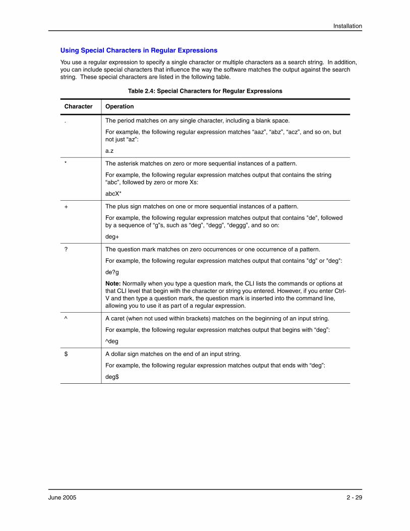
Installation
Using Special Characters in Regular Expressions
You use a regular expression to specify a single character or multiple characters as a search string. In addition, you can include special characters that influence the way the software matches the output against the search string. These special characters are listed in the following table.
Table 2.4: Special Characters for Regular Expressions
Character Operation
. The period matches on any single character, including a blank space.
For example, the following regular expression matches “aaz”, “abz”, “acz”, and so on, but not just “az”:
a.z
* The asterisk matches on zero or more sequential instances of a pattern.
For example, the following regular expression matches output that contains the string “abc”, followed by zero or more Xs:
abcX*
+ The plus sign matches on one or more sequential instances of a pattern.
For example, the following regular expression matches output that contains "de", followed by a sequence of “g”s, such as “deg”, “degg”, “deggg”, and so on:
deg+
? The question mark matches on zero occurrences or one occurrence of a pattern.
For example, the following regular expression matches output that contains "dg" or "deg":
de?g
Note: Normally when you type a question mark, the CLI lists the commands or options at that CLI level that begin with the character or string you entered. However, if you enter Ctrl-V and then type a question mark, the question mark is inserted into the command line, allowing you to use it as part of a regular expression.
^ A caret (when not used within brackets) matches on the beginning of an input string.
For example, the following regular expression matches output that begins with “deg”:
^deg
$ A dollar sign matches on the end of an input string.
For example, the following regular expression matches output that ends with “deg”:
deg$
June 2005 2 - 29
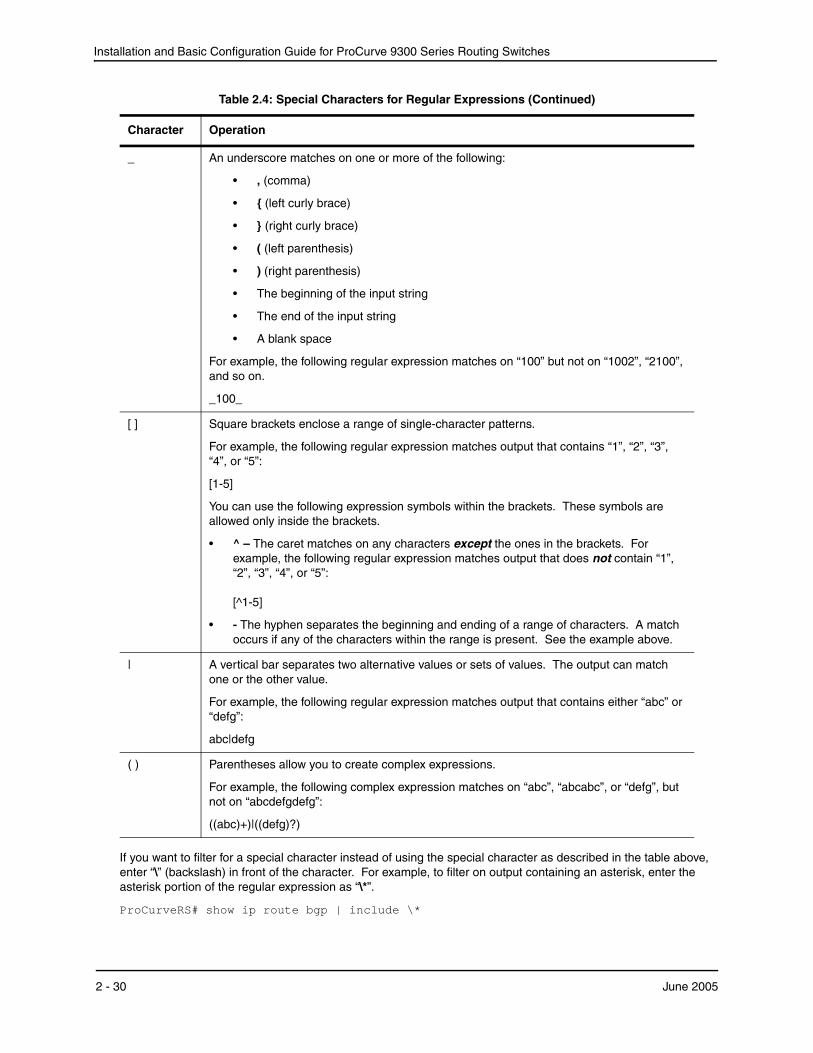
Installation and Basic Configuration Guide for ProCurve 9300 Series Routing Switches
If you want to filter for a special character instead of using the special character as described in the table above, enter “\” (backslash) in front of the character. For example, to filter on output containing an asterisk, enter the asterisk portion of the regular expression as “\*”.
ProCurveRS# show ip route bgp | include \*
_ An underscore matches on one or more of the following:
• , (comma)
• { (left curly brace)
• } (right curly brace)
• ( (left parenthesis)
• ) (right parenthesis)
• The beginning of the input string
• The end of the input string
• A blank space
For example, the following regular expression matches on “100” but not on “1002”, “2100”, and so on.
_100_
[ ] Square brackets enclose a range of single-character patterns.
For example, the following regular expression matches output that contains “1”, “2”, “3”, “4”, or “5”:
[1-5]
You can use the following expression symbols within the brackets. These symbols are allowed only inside the brackets.
• ^ – The caret matches on any characters except the ones in the brackets. For example, the following regular expression matches output that does not contain “1”, “2”, “3”, “4”, or “5”: [^1-5]
• - The hyphen separates the beginning and ending of a range of characters. A match occurs if any of the characters within the range is present. See the example above.
| A vertical bar separates two alternative values or sets of values. The output can match one or the other value.
For example, the following regular expression matches output that contains either “abc” or “defg”:
abc|defg
( ) Parentheses allow you to create complex expressions.
For example, the following complex expression matches on “abc”, “abcabc”, or “defg”, but not on “abcdefgdefg”:
((abc)+)|((defg)?)
Table 2.4: Special Characters for Regular Expressions (Continued)
Character Operation
2 - 30 June 2005
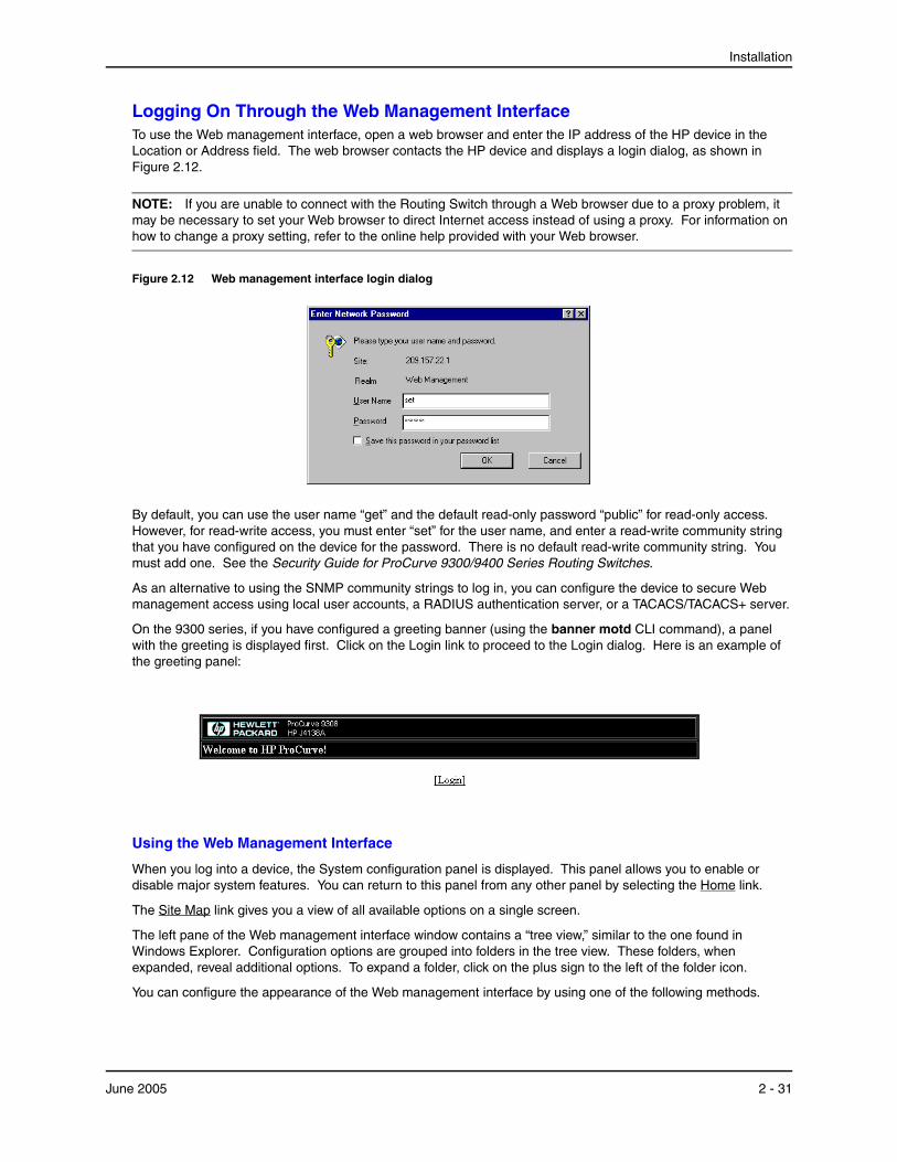
Installation
Logging On Through the Web Management InterfaceTo use the Web management interface, open a web browser and enter the IP address of the HP device in the Location or Address field. The web browser contacts the HP device and displays a login dialog, as shown in Figure 2.12.
NOTE: If you are unable to connect with the Routing Switch through a Web browser due to a proxy problem, it may be necessary to set your Web browser to direct Internet access instead of using a proxy. For information on how to change a proxy setting, refer to the online help provided with your Web browser.
Figure 2.12 Web management interface login dialog
By default, you can use the user name “get” and the default read-only password “public” for read-only access. However, for read-write access, you must enter “set” for the user name, and enter a read-write community string that you have configured on the device for the password. There is no default read-write community string. You must add one. See the Security Guide for ProCurve 9300/9400 Series Routing Switches.
As an alternative to using the SNMP community strings to log in, you can configure the device to secure Web management access using local user accounts, a RADIUS authentication server, or a TACACS/TACACS+ server.
On the 9300 series, if you have configured a greeting banner (using the banner motd CLI command), a panel with the greeting is displayed first. Click on the Login link to proceed to the Login dialog. Here is an example of the greeting panel:
Using the Web Management Interface
When you log into a device, the System configuration panel is displayed. This panel allows you to enable or disable major system features. You can return to this panel from any other panel by selecting the Home link.
The Site Map link gives you a view of all available options on a single screen.
The left pane of the Web management interface window contains a “tree view,” similar to the one found in Windows Explorer. Configuration options are grouped into folders in the tree view. These folders, when expanded, reveal additional options. To expand a folder, click on the plus sign to the left of the folder icon.
You can configure the appearance of the Web management interface by using one of the following methods.
June 2005 2 - 31

Installation and Basic Configuration Guide for ProCurve 9300 Series Routing Switches
USING THE CLI
Using the CLI, you can modify the appearance of the Web management interface with the web-management command.
To cause the Web management interface to display the List view by default:
ProCurveRS(config)# web-management list-menu
To disable the front panel frame:
ProCurveRS(config)# no web-management front-panel
When you save the configuration with the write memory command, the changes will take place the next time you start the Web management interface, or if you are currently running the Web management interface, the changes will take place when you click the Refresh button on your browser.
USING THE WEB MANAGEMENT INTERFACE
1. Click on the plus sign next to Configure in the tree view to expand the list of configuration options.
2. Click on the plus sign next to System in the tree view to expand the list of system configuration links.
3. Click on the plus sign next to Management in the tree view to expand the list of system management links.
4. Click on the Web Preference link to display the Web Management Preferences panel.
5. Enable or disable elements on the Web management interface by clicking on the appropriate radio buttons on the panel. The following figure identifies the elements you can change.
Front Panel
Front Panel
Page Menu
Bottom Frame
Menu Frame
Menu Type(Tree View
Frame
shown)
NOTE: The tree view is available when you use the Web management interface with Netscape 4.0 or higher or Internet Explorer 4.0 or higher browsers. If you use the Web management interface with an older browser, the Web management interface displays the List view only, and the Web Management Preferences panel does not include an option to display the tree view.
6. When you have finished, click the Apply button on the panel, then click the Refresh button on your browser to activate the changes.
2 - 32 June 2005
Installation
7. To save the configuration, click the plus sign next to the Command folder, then click the Save to Flash link.
NOTE: The only changes that become permanent are the settings to the Menu Type and the Front Panel Frame. Any other elements you enable or disable will go back to their default settings the next time you start the Web management interface.
Swapping Modules
Removing the Old ModuleTo remove anon- management module, disable the module first before removing it. Disabling the module before removing it prevent a brief service interruption on other non-management modules.The brief interruption can be caused by the routing switch reinitializing other modules when you remove an enabled module.
NOTE: The disable module and enable module commands are not applicable to management modules. You do not need to disable a management module in software before removing it.
To disable a non-management module, enter a command such as the following at the Privileged EXEC level of the CLI:
ProCurveRS# disable module 3
This command disables the module in slot 3.
Syntax: disable module <slot-num>
The <slot-num> parameter specifies the slot number.
• Slots in a 4-slot chassis are numbered 1 – 4, from top to bottom.
• Slots in an 8-slot chassis are numbered 1 – 8, from left to right.
• Slots in a 15-slot chassis are numbered 1 – 15, from left to right.
NOTE: If you remove the module without first disabling it, the routing switch re-initializes the other modules in the chassis, causing a brief interruption in service after which normal operation resumes.
If you decide, after disabling a module, that you do not want to remove the module, re-enable the module using the following command:
ProCurveRS# enable module 3
Syntax: enable module <slot-num>
NOTE: You do not need to enable a module after inserting it in the chassis. The module is automatically enabled when you insert the module into a live chassis or when you power on the chassis.
NOTE: If you plan to replace a removed module with a different type of module, you must configure the slot for the module. To configure a slot for a module, use the module command at the global CONFIG level of the CLI. See “Installing the New Module” on page 2-33.
Installing the New ModulePhysically insert a module into a Routing Switch. Next, you need to enter the location and type of module in the software, unless you either reboot the device or are replacing one module with another of the same type.
Slots on the 9304M are numbered 1 – 4, from top to bottom.
Slots on the 9308M are numbered 1 – 8, from left to right.
June 2005 2 - 33
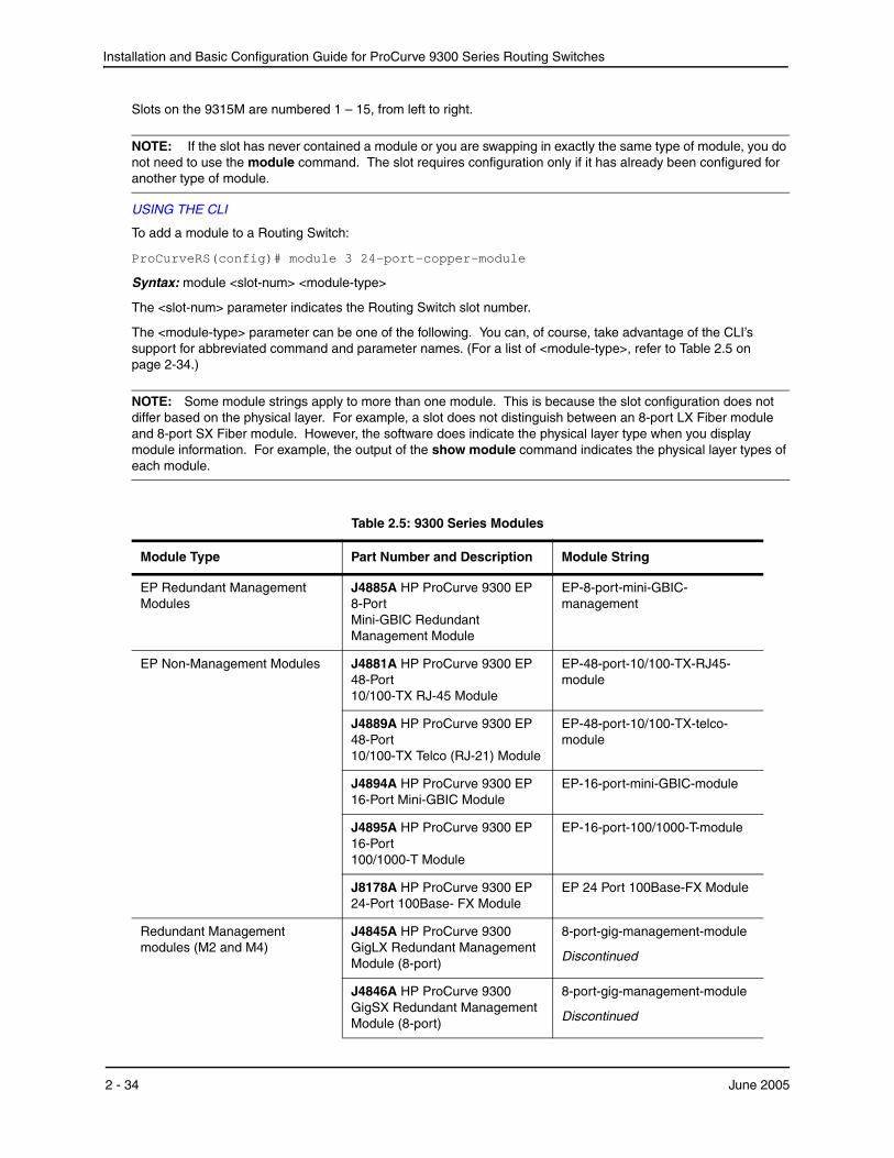
Installation and Basic Configuration Guide for ProCurve 9300 Series Routing Switches
Slots on the 9315M are numbered 1 – 15, from left to right.
NOTE: If the slot has never contained a module or you are swapping in exactly the same type of module, you do not need to use the module command. The slot requires configuration only if it has already been configured for another type of module.
USING THE CLI
To add a module to a Routing Switch:
ProCurveRS(config)# module 3 24-port-copper-module
Syntax: module <slot-num> <module-type>
The <slot-num> parameter indicates the Routing Switch slot number.
The <module-type> parameter can be one of the following. You can, of course, take advantage of the CLI’s support for abbreviated command and parameter names. (For a list of <module-type>, refer to Table 2.5 on page 2-34.)
NOTE: Some module strings apply to more than one module. This is because the slot configuration does not differ based on the physical layer. For example, a slot does not distinguish between an 8-port LX Fiber module and 8-port SX Fiber module. However, the software does indicate the physical layer type when you display module information. For example, the output of the show module command indicates the physical layer types of each module.
Table 2.5: 9300 Series Modules
Module Type Part Number and Description Module String
EP Redundant Management Modules
J4885A HP ProCurve 9300 EP 8-Port Mini-GBIC Redundant Management Module
EP-8-port-mini-GBIC-management
EP Non-Management Modules J4881A HP ProCurve 9300 EP 48-Port 10/100-TX RJ-45 Module
EP-48-port-10/100-TX-RJ45-module
J4889A HP ProCurve 9300 EP 48-Port 10/100-TX Telco (RJ-21) Module
EP-48-port-10/100-TX-telco-module
J4894A HP ProCurve 9300 EP 16-Port Mini-GBIC Module
EP-16-port-mini-GBIC-module
J4895A HP ProCurve 9300 EP 16-Port 100/1000-T Module
EP-16-port-100/1000-T-module
J8178A HP ProCurve 9300 EP 24-Port 100Base- FX Module
EP 24 Port 100Base-FX Module
Redundant Management modules (M2 and M4)
J4845A HP ProCurve 9300 GigLX Redundant Management Module (8-port)
8-port-gig-management-module
Discontinued
J4846A HP ProCurve 9300 GigSX Redundant Management Module (8-port)
8-port-gig-management-module
Discontinued
2 - 34 June 2005
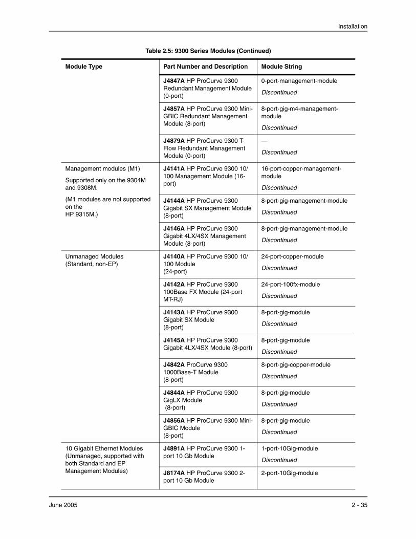
Installation
J4847A HP ProCurve 9300 Redundant Management Module (0-port)
0-port-management-module
Discontinued
J4857A HP ProCurve 9300 Mini-GBIC Redundant Management Module (8-port)
8-port-gig-m4-management-module
Discontinued
J4879A HP ProCurve 9300 T-Flow Redundant Management Module (0-port)
—
Discontinued
Management modules (M1)
Supported only on the 9304M and 9308M.
(M1 modules are not supported on the HP 9315M.)
J4141A HP ProCurve 9300 10/100 Management Module (16-port)
16-port-copper-management-module
Discontinued
J4144A HP ProCurve 9300 Gigabit SX Management Module (8-port)
8-port-gig-management-module
Discontinued
J4146A HP ProCurve 9300 Gigabit 4LX/4SX Management Module (8-port)
8-port-gig-management-module
Discontinued
Unmanaged Modules (Standard, non-EP)
J4140A HP ProCurve 9300 10/100 Module (24-port)
24-port-copper-module
Discontinued
J4142A HP ProCurve 9300 100Base FX Module (24-port MT-RJ)
24-port-100fx-module
Discontinued
J4143A HP ProCurve 9300 Gigabit SX Module (8-port)
8-port-gig-module
Discontinued
J4145A HP ProCurve 9300 Gigabit 4LX/4SX Module (8-port)
8-port-gig-module
Discontinued
J4842A ProCurve 9300 1000Base-T Module (8-port)
8-port-gig-copper-module
Discontinued
J4844A HP ProCurve 9300 GigLX Module (8-port)
8-port-gig-module
Discontinued
J4856A HP ProCurve 9300 Mini-GBIC Module (8-port)
8-port-gig-module
Discontinued
10 Gigabit Ethernet Modules (Unmanaged, supported with both Standard and EP Management Modules)
J4891A HP ProCurve 9300 1-port 10 Gb Module
1-port-10Gig-module
Discontinued
J8174A HP ProCurve 9300 2-port 10 Gb Module
2-port-10Gig-module
Table 2.5: 9300 Series Modules (Continued)
Module Type Part Number and Description Module String
June 2005 2 - 35
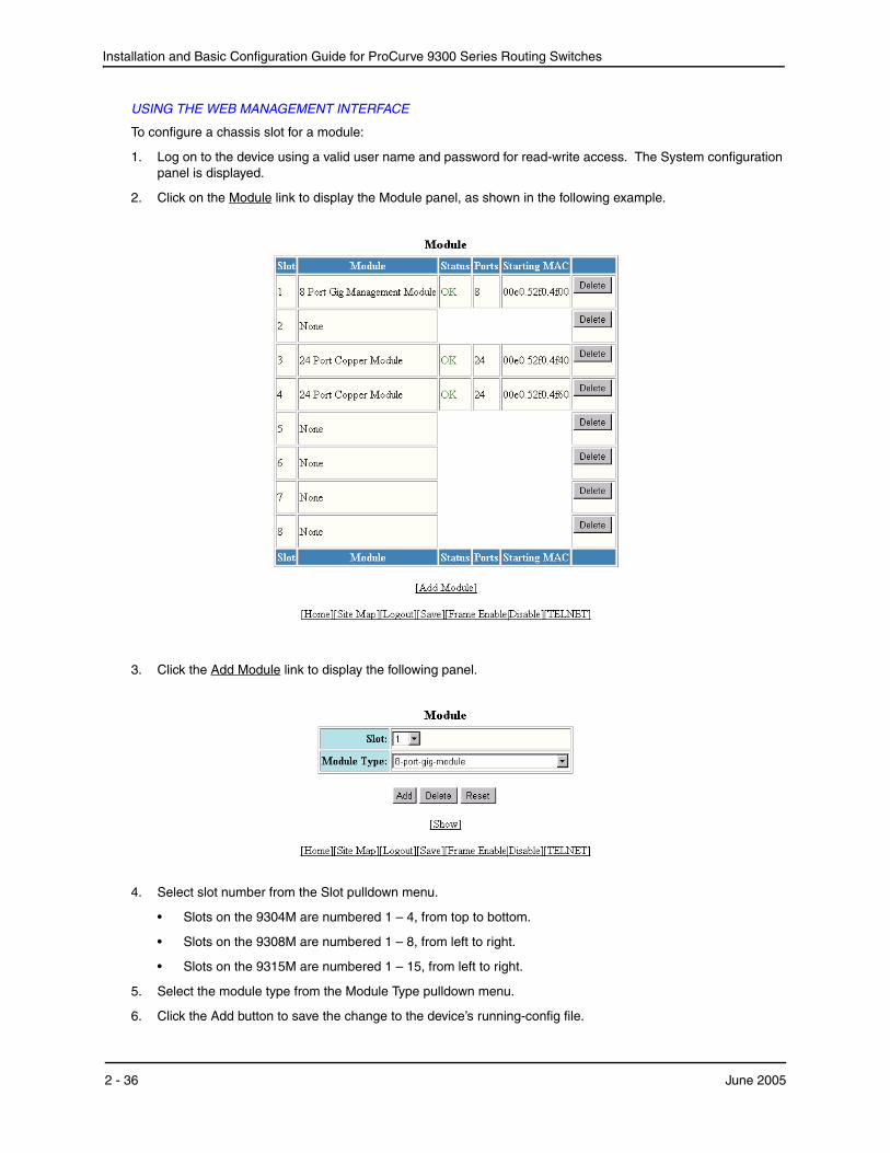
Installation and Basic Configuration Guide for ProCurve 9300 Series Routing Switches
USING THE WEB MANAGEMENT INTERFACE
To configure a chassis slot for a module:
1. Log on to the device using a valid user name and password for read-write access. The System configuration panel is displayed.
2. Click on the Module link to display the Module panel, as shown in the following example.
3. Click the Add Module link to display the following panel.
4. Select slot number from the Slot pulldown menu.
• Slots on the 9304M are numbered 1 – 4, from top to bottom.
• Slots on the 9308M are numbered 1 – 8, from left to right.
• Slots on the 9315M are numbered 1 – 15, from left to right.
5. Select the module type from the Module Type pulldown menu.
6. Click the Add button to save the change to the device’s running-config file.
2 - 36 June 2005

Installation
7. Select the Save link at the bottom of the dialog. Select Yes when prompted to save the configuration change to the startup-config file on the device’s flash memory.
Next StepsOnce the initial installation steps are completed, you can proceed with enabling routing protocols and configuring specific features on the Routing Switches as described in “Configuring Basic Features” on page 6-1.
Configuration details for all routing protocols and advanced VLAN features can be found in the Advanced Configuration and Management Guide for ProCurve 9300/9400 Series Routing Switches.
June 2005 2 - 37

Installation and Basic Configuration Guide for ProCurve 9300 Series Routing Switches
2 - 38 June 2005
Chapter 3Using Redundant Management Modules
This chapter describes the redundant management modules and how to configure and manage them. Redundant management modules provide increased routing capacity and failover for 9300 series Routing Switches.
See the following sections for information:
• “Configuring the Redundant Management Parameters” on page 3-3
• “File Synchronization Between the Active and Standby Redundant Management Modules” on page 3-10
• “Switching Over to the Standby Redundant Management Module” on page 3-15
The redundant management modules are fully-functional CPU management modules for Routing Switches. You can use one or two redundant management modules in these devices.
You can use one or two redundant management modules in a Routing Switch. Using two redundant management modules adds fault protection against system outage. The two modules work together as active and standby management modules. If the active module becomes unavailable, the standby module automatically takes over system operation.
NOTE: This chapter does not describe management features that are specific to the T-Flow Redundant Management Module, such as logging on to individual CPUs. See “Using the T-Flow Redundant Management Module” on page 4-1.
Configuration Considerations• The Management Modules 2 and 4 support redundancy.
• You can use one or two redundant management modules in a Routing Switch.
• You cannot use older management modules in the same Routing Switch with redundant management modules.
Temperature SensorThe redundant management modules contain a temperature sensor. You can use the CLI or Web management interface to display the active redundant management module's temperature and to change the warning and shutdown temperature levels. See “Using the Temperature Sensor” on page 6-47.
June 2005 3 - 1
Installation and Basic Configuration Guide for ProCurve 9300 Series Routing Switches
SwitchoverWhen you power on or reload a Routing Switch that contains two redundant management modules, the active redundant management module is selected based on the chassis slot previously specified by you or according to the lower slot number.
After the active module is selected, the active module loads its boot and flash code (boot and system software) and its system-config file and manages the system. The standby module also boots, using its own boot code but using the active module's flash code and system-config file. The standby module monitors the heartbeat of the active module. If the active module becomes unavailable, the standby module notices the absence of the heartbeat and assumes management control of the system.
NOTE: By default, the system does not use the boot code on the active module to boot the standby module. If you upgrade the boot code on the active module and the code contains a problem, you can still use the system by running the older boot code that is on the standby module. You can configure the standby to synchronize with the active module's boot code. See “File Synchronization Between the Active and Standby Redundant Management Modules” on page 3-10.
The standby module's system-config file is updated whenever the system-config file on the active module is updated. In addition, the running-config file on the standby module is updated at regular intervals to match the active module's running-config data. Thus, when a switchover occurs, the standby module also can reinstate the configuration data in the active module's running-config.
Following this switchover to the standby module, the standby module becomes the active module and continues to manage the system. When the other redundant management module (the one that used to be the active module) becomes available again or is replaced, that module becomes the standby module.
The active module also monitors the standby module. If the standby module becomes unavailable, the active module tries to reboot the standby module. You can display the status of each module using the CLI or the Web management interface, as described in “Determining Redundant Management Module Status” on page 3-7.
Management SessionsYou can establish management sessions only with the active redundant management module, not with the standby redundant management module. During switchover, all the CLI, Web management interface, and SNMP management application sessions open on the system are closed. To manage the system following a switchover, you must open a new management session. Although the system's MAC addresses change following switchover, the IP addresses do not. You can open new management sessions on the same IP addresses you were using before the switchover if desired.
To establish a serial connection to the CLI, you must move the serial cable to the serial port on the active redundant management module.
Syslog and SNMP TrapsWhen a switchover occurs, the software sends a Syslog message to the local Syslog buffer and also to the Syslog server, if you have configured the HP device to use one. In addition, if you have configured an SNMP trap receiver, the software sends an SNMP trap to the receiver.
When the system is powered on or otherwise reset normally, the software sends a cold start message and trap. However, if the system is reset as the result of switchover to the standby redundant management module, the software instead sends a switchover message and trap.
MAC Address ChangesThe MAC addresses in the system are based on the MAC address of the active management module. During switchover, the system's MAC addresses change and the system sends out gratuitous ARP requests to flush the old MAC addresses from the ARP caches on attached IP devices, and update the caches with the HP device’s new MAC addresses.
3 - 2 June 2005
Using Redundant Management Modules
NOTE: The 15-slot chassis makes use of locally administered MAC addresses. If your site already uses locally administered MAC addresses of the HP OUI, which is 00e052, there could be a MAC address conflict with one of the ports on the HP device.
Configuring the Redundant Management ParametersYou can configure the following redundant management module parameters:
• Installation parameters:
• Slot configuration. As with other module types, you must configure a chassis slot for the type of module you are installing in the slot.
• Active redundant management module slot. By default, the redundant management module with the lower slot number is the active module.
• Operational parameters:
• Boot code synchronization. By default, the standby redundant management module does not automatically synchronize to the boot code version installed on the active module. The standby module does automatically synchronize to the flash code (system software) on the active module.
• Synchronization interval for running-config file
• Warning and shutdown temperatures
Installing Redundant Management ModulesTo install a redundant management module, perform the following tasks:
• Configure the chassis slot to receive the module.
NOTE: The system must be running a version of software that supports the module you want to install.
• Insert the module.
• Specify the default active module (if you do not want to use the system default, which is the redundant management module with the lower slot number).
In addition, if you use a TFTP or BootP server to boot the active module, you need to copy the flash code (system software) into the primary or secondary flash on the active redundant management module, then direct the active redundant management module to use the code to boot the standby module.
A standby redundant management module does not boot from a TFTP or BootP server.
NOTE: The slots in a 15-slot chassis are divided among 4 internal regions. Slots 1 – 4 belong to the same region; slots 5 – 8 belong to the same region; slots 9 – 12 belong to the same region, and slots 13 – 15 belong to the same region. If you are using redundant management modules, HP recommends that you place both management modules in slots belonging to the same region. For example, if you place one management module in slot 5, HP recommends that you place the other management module in slot 6, 7, or 8. This note does not apply to 4-slot or 8-slot chassis.
Configuring the Chassis to Receive the Module
When you plan to insert a module into a chassis slot, you first must configure the slot to receive the module unless the slot already contains the same type of module.
June 2005 3 - 3
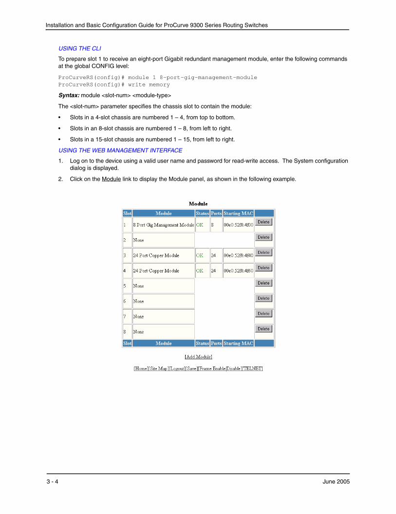
Installation and Basic Configuration Guide for ProCurve 9300 Series Routing Switches
USING THE CLI
To prepare slot 1 to receive an eight-port Gigabit redundant management module, enter the following commands at the global CONFIG level:
ProCurveRS(config)# module 1 8-port-gig-management-module ProCurveRS(config)# write memory
Syntax: module <slot-num> <module-type>
The <slot-num> parameter specifies the chassis slot to contain the module:
• Slots in a 4-slot chassis are numbered 1 – 4, from top to bottom.
• Slots in an 8-slot chassis are numbered 1 – 8, from left to right.
• Slots in a 15-slot chassis are numbered 1 – 15, from left to right.
USING THE WEB MANAGEMENT INTERFACE
1. Log on to the device using a valid user name and password for read-write access. The System configuration dialog is displayed.
2. Click on the Module link to display the Module panel, as shown in the following example.
3 - 4 June 2005
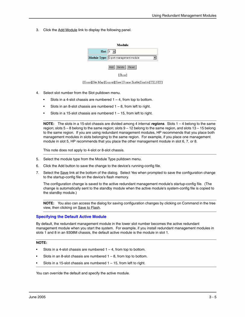
Using Redundant Management Modules
3. Click the Add Module link to display the following panel.
4. Select slot number from the Slot pulldown menu.
• Slots in a 4-slot chassis are numbered 1 – 4, from top to bottom.
• Slots in an 8-slot chassis are numbered 1 – 8, from left to right.
• Slots in a 15-slot chassis are numbered 1 – 15, from left to right.
NOTE: The slots in a 15-slot chassis are divided among 4 internal regions. Slots 1 – 4 belong to the same region; slots 5 – 8 belong to the same region; slots 9 – 12 belong to the same region, and slots 13 – 15 belong to the same region. If you are using redundant management modules, HP recommends that you place both management modules in slots belonging to the same region. For example, if you place one management module in slot 5, HP recommends that you place the other management module in slot 6, 7, or 8. This note does not apply to 4-slot or 8-slot chassis.
5. Select the module type from the Module Type pulldown menu.
6. Click the Add button to save the change to the device’s running-config file.
7. Select the Save link at the bottom of the dialog. Select Yes when prompted to save the configuration change to the startup-config file on the device’s flash memory.
The configuration change is saved to the active redundant management module's startup-config file. (The change is automatically sent to the standby module when the active module's system-config file is copied to the standby module.)
NOTE: You also can access the dialog for saving configuration changes by clicking on Command in the tree view, then clicking on Save to Flash.
Specifying the Default Active Module
By default, the redundant management module in the lower slot number becomes the active redundant management module when you start the system. For example, if you install redundant management modules in slots 1 and 8 in an 9308M chassis, the default active module is the module in slot 1.
NOTE:
• Slots in a 4-slot chassis are numbered 1 – 4, from top to bottom.
• Slots in an 8-slot chassis are numbered 1 – 8, from top to bottom.
• Slots in a 15-slot chassis are numbered 1 – 15, from left to right.
You can override the default and specify the active module.
June 2005 3 - 5
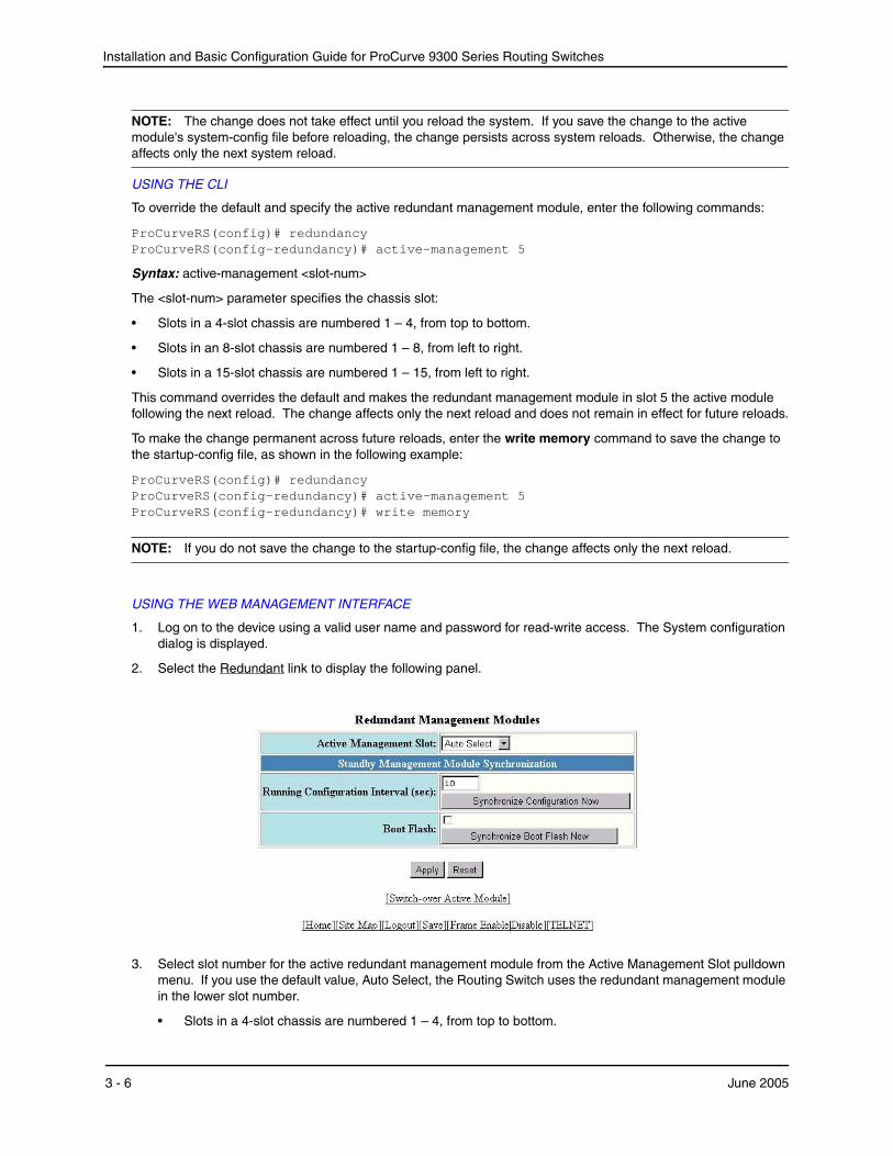
Installation and Basic Configuration Guide for ProCurve 9300 Series Routing Switches
NOTE: The change does not take effect until you reload the system. If you save the change to the active module's system-config file before reloading, the change persists across system reloads. Otherwise, the change affects only the next system reload.
USING THE CLI
To override the default and specify the active redundant management module, enter the following commands:
ProCurveRS(config)# redundancy ProCurveRS(config-redundancy)# active-management 5
Syntax: active-management <slot-num>
The <slot-num> parameter specifies the chassis slot:
• Slots in a 4-slot chassis are numbered 1 – 4, from top to bottom.
• Slots in an 8-slot chassis are numbered 1 – 8, from left to right.
• Slots in a 15-slot chassis are numbered 1 – 15, from left to right.
This command overrides the default and makes the redundant management module in slot 5 the active module following the next reload. The change affects only the next reload and does not remain in effect for future reloads.
To make the change permanent across future reloads, enter the write memory command to save the change to the startup-config file, as shown in the following example:
ProCurveRS(config)# redundancy ProCurveRS(config-redundancy)# active-management 5 ProCurveRS(config-redundancy)# write memory
NOTE: If you do not save the change to the startup-config file, the change affects only the next reload.
USING THE WEB MANAGEMENT INTERFACE
1. Log on to the device using a valid user name and password for read-write access. The System configuration dialog is displayed.
2. Select the Redundant link to display the following panel.
3. Select slot number for the active redundant management module from the Active Management Slot pulldown menu. If you use the default value, Auto Select, the Routing Switch uses the redundant management module in the lower slot number.
• Slots in a 4-slot chassis are numbered 1 – 4, from top to bottom.
3 - 6 June 2005
Using Redundant Management Modules
• Slots in an 8-slot chassis are numbered 1 – 8, from left to right.
• Slots in a 15-slot chassis are numbered 1 – 15, from left to right.
4. Click the Apply button to send the configuration change to the active module’s running-config file.
5. If you want the change to remain in effect following the next system reload, select the Save link to save the configuration change to the active redundant management module's startup-config file. (The change is automatically sent to the standby module when the active module's system-config file is copied to the standby module.)
NOTE: If you do not save the change to the startup-config file, the change affects only the next reload.
NOTE: The other options on this panel are described in later sections.
Inserting the Module
You can remove and insert modules when the system is powered on. Make sure you adhere to the cautions noted in “Installation Precautions” on page 2-3.
1. Put on an ESD wrist strap and attach the copper tape to a metal surface (such as an equipment rack) to act as ground.
2. Remove the module or faceplate from the slot:
3. If you are replacing another module, loosen the two screws on the module you are removing.
• Pull the card ejectors towards you, away from the module front panel. The card will unseat from the backplane.
• Pull the module out of the chassis and place in an anti-static bag for storage.
4. If you are installing a redundant management module in an unoccupied module slot, remove the blank faceplate from the slot in which the module is to be installed. Place the blank faceplate in a safe place for future use.
5. Remove the redundant management module from its packaging.
6. Insert the module into the chassis slot and glide the card along the card guide until the card ejectors on the front of the module touch the chassis.
• Modules for 4-slot chassis slide in horizontally with the module label on the left.
• Modules for 8-slot chassis slide in vertically with the module label at the top.
• Modules for 15-slot chassis slide in vertically with the module label at the top.
7. Push the ejectors toward the center of the module until they are flush with the front panel of the module. The module will be fully seated in the backplane.
8. Tighten the two screws at either end of the module.
9. If you do not use one or more of the slots, make sure that a slot faceplate is still attached over each unused slot for safe operation and proper system cooling.
Determining Redundant Management Module StatusYou can determine the status of a redundant management module in the following ways:
• Status LED – The redundant management module has two green LEDs on the right side of the CLI serial port. The lower LED shows the management status.
• Module information in software – The module information displayed by the software indicates whether the module is the active module, the standby module, or has another status.
June 2005 3 - 7
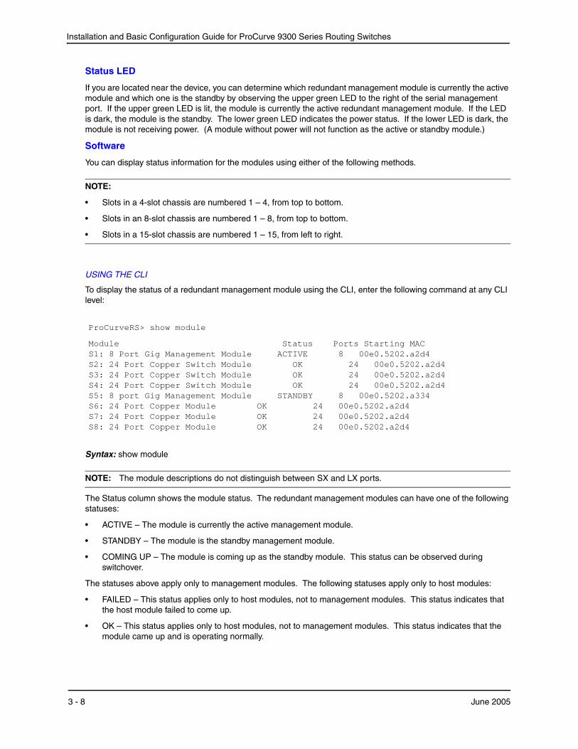
Installation and Basic Configuration Guide for ProCurve 9300 Series Routing Switches
Status LED
If you are located near the device, you can determine which redundant management module is currently the active module and which one is the standby by observing the upper green LED to the right of the serial management port. If the upper green LED is lit, the module is currently the active redundant management module. If the LED is dark, the module is the standby. The lower green LED indicates the power status. If the lower LED is dark, the module is not receiving power. (A module without power will not function as the active or standby module.)
Software
You can display status information for the modules using either of the following methods.
NOTE:
• Slots in a 4-slot chassis are numbered 1 – 4, from top to bottom.
• Slots in an 8-slot chassis are numbered 1 – 8, from top to bottom.
• Slots in a 15-slot chassis are numbered 1 – 15, from left to right.
USING THE CLI
To display the status of a redundant management module using the CLI, enter the following command at any CLI level:
ProCurveRS> show module
Module Status Ports Starting MAC S1: 8 Port Gig Management Module ACTIVE 8 00e0.5202.a2d4 S2: 24 Port Copper Switch Module OK 24 00e0.5202.a2d4 S3: 24 Port Copper Switch Module OK 24 00e0.5202.a2d4 S4: 24 Port Copper Switch Module OK 24 00e0.5202.a2d4 S5: 8 port Gig Management Module STANDBY 8 00e0.5202.a334 S6: 24 Port Copper Module OK 24 00e0.5202.a2d4 S7: 24 Port Copper Module OK 24 00e0.5202.a2d4 S8: 24 Port Copper Module OK 24 00e0.5202.a2d4
Syntax: show module
NOTE: The module descriptions do not distinguish between SX and LX ports.
The Status column shows the module status. The redundant management modules can have one of the following statuses:
• ACTIVE – The module is currently the active management module.
• STANDBY – The module is the standby management module.
• COMING UP – The module is coming up as the standby module. This status can be observed during switchover.
The statuses above apply only to management modules. The following statuses apply only to host modules:
• FAILED – This status applies only to host modules, not to management modules. This status indicates that the host module failed to come up.
• OK – This status applies only to host modules, not to management modules. This status indicates that the module came up and is operating normally.
3 - 8 June 2005
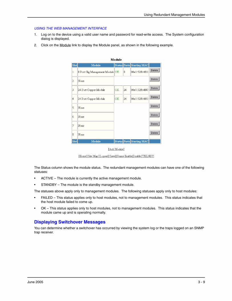
Using Redundant Management Modules
USING THE WEB MANAGEMENT INTERFACE
1. Log on to the device using a valid user name and password for read-write access. The System configuration dialog is displayed.
2. Click on the Module link to display the Module panel, as shown in the following example.
The Status column shows the module status. The redundant management modules can have one of the following statuses:
• ACTIVE – The module is currently the active management module.
• STANDBY – The module is the standby management module.
The statuses above apply only to management modules. The following statuses apply only to host modules:
• FAILED – This status applies only to host modules, not to management modules. This status indicates that the host module failed to come up.
• OK – This status applies only to host modules, not to management modules. This status indicates that the module came up and is operating normally.
Displaying Switchover MessagesYou can determine whether a switchover has occurred by viewing the system log or the traps logged on an SNMP trap receiver.
June 2005 3 - 9
Installation and Basic Configuration Guide for ProCurve 9300 Series Routing Switches
USING THE CLI
To view the system log, enter the following command at any level of the CLI:
ProCurveRS> show log
Syslog logging: enabled (0 messages dropped, 0 flushes, 0 overruns) Buffer logging: level ACDMEINW, 8 messages logged level code: A=alert C=critical D=debugging M=emergency E=error I=informational N=notification W=warning Static Log Buffer: Dynamic Log Buffer (50 entries): at 0 days 0 hours 0 minutes 0 seconds, level alert Management module at slot 1 state changed, changed state from standby to active
USING THE WEB MANAGEMENT INTERFACE
1. Log on to the device using a valid user name and password for read-write access. The System configuration dialog is displayed.
2. Click on the plus sign next to Monitor in the tree view to display the Monitor options.
3. Select the System Log link to display the system log.
File Synchronization Between the Active and Standby Redundant Management ModulesEach redundant management module contains four files that can be synchronized between the two modules:
• Boot code – The code the module runs when it first starts up. By default, the boot code is not synchronized between redundant management modules. This ensures that the system can still operate if a new version of boot code contains a bug that prohibits normal operation. If the new code on the active module does not work properly, the system can still run using the older version of boot code on the standby module. You can configure the standby redundant management module to synchronize with the active redundant management module's boot code whenever the boot code on the active module is updated or the system starts up.
• Flash code (system software) – The flash code is automatically synchronized between the redundant management modules. When the system starts up, the active redundant management module sends its flash code to the standby redundant management module to boot the module.
NOTE: The flash code on T-Flow TSP CPUs (non-management CPUs) is not automatically synchronized. To synchronize the flash code on the TSP CPUs, use the vm copy tftp flash command, described in “Immediately Synchronizing Software” on page 3-13. The flash code on the CPU is automatically synchronized.
• System-config file – The system-config file is automatically copied from the active redundant management module to the standby redundant management module when the system starts up. The file is also copied to the standby module whenever you save changes to the file. If switchover occurs, the standby redundant management module loads system parameters from the running-config data that was last received from the active redundant management module. If the standby module did not receive running-config data from the active module, the standby module uses configuration information in the system-config file copied from the active module.
3 - 10 June 2005
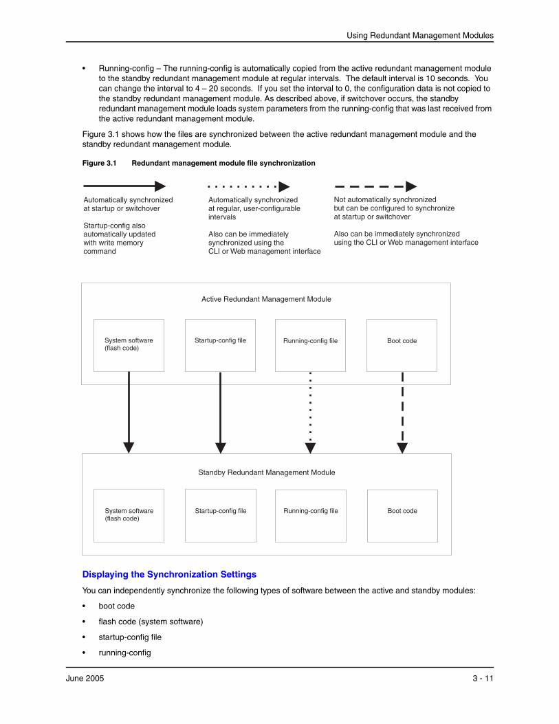
Using Redundant Management Modules
• Running-config – The running-config is automatically copied from the active redundant management module to the standby redundant management module at regular intervals. The default interval is 10 seconds. You can change the interval to 4 – 20 seconds. If you set the interval to 0, the configuration data is not copied to the standby redundant management module. As described above, if switchover occurs, the standby redundant management module loads system parameters from the running-config that was last received from the active redundant management module.
Figure 3.1 shows how the files are synchronized between the active redundant management module and the standby redundant management module.
Figure 3.1 Redundant management module file synchronization
Standby ModuleRedundant Management
Boot codeSystem software(flash code)
Running-config fileStartup-config file
Not automatically synchronizedbut can be configured to synchronizeat startup or switchover
Also can be immediately synchronizedusing the CLI or Web management interface
Boot codeSystem software(flash code)
Running-config fileStartup-config file
Active ModuleRedundant Management
Automatically synchronizedat startup or switchover
Startup-config alsoautomatically updatedwith write memorycommand
Automatically synchronizedat regular, user-configurableintervals
Also can be immediatelysynchronized using theCLI or Web management interface
Displaying the Synchronization Settings
You can independently synchronize the following types of software between the active and standby modules:
• boot code
• flash code (system software)
• startup-config file
• running-config
June 2005 3 - 11
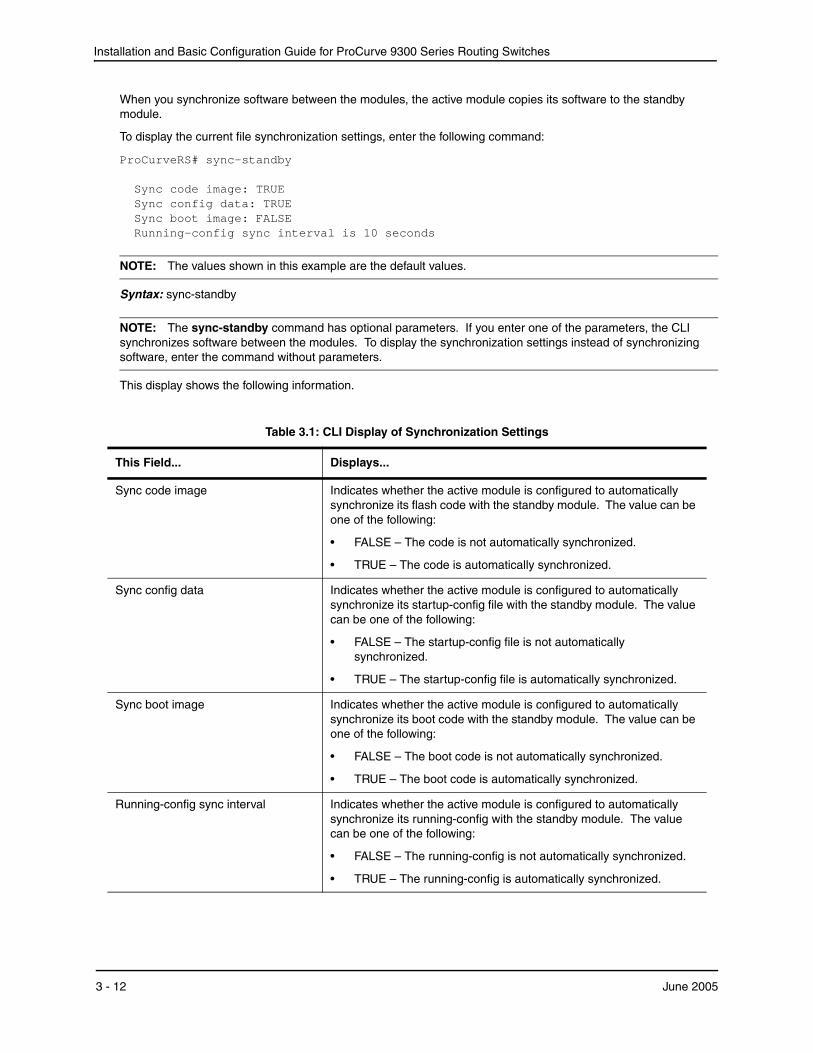
Installation and Basic Configuration Guide for ProCurve 9300 Series Routing Switches
When you synchronize software between the modules, the active module copies its software to the standby module.
To display the current file synchronization settings, enter the following command:
ProCurveRS# sync-standby Sync code image: TRUE Sync config data: TRUE Sync boot image: FALSE Running-config sync interval is 10 seconds
NOTE: The values shown in this example are the default values.
Syntax: sync-standby
NOTE: The sync-standby command has optional parameters. If you enter one of the parameters, the CLI synchronizes software between the modules. To display the synchronization settings instead of synchronizing software, enter the command without parameters.
This display shows the following information.
Table 3.1: CLI Display of Synchronization Settings
This Field... Displays...
Sync code image Indicates whether the active module is configured to automatically synchronize its flash code with the standby module. The value can be one of the following:
• FALSE – The code is not automatically synchronized.
• TRUE – The code is automatically synchronized.
Sync config data Indicates whether the active module is configured to automatically synchronize its startup-config file with the standby module. The value can be one of the following:
• FALSE – The startup-config file is not automatically synchronized.
• TRUE – The startup-config file is automatically synchronized.
Sync boot image Indicates whether the active module is configured to automatically synchronize its boot code with the standby module. The value can be one of the following:
• FALSE – The boot code is not automatically synchronized.
• TRUE – The boot code is automatically synchronized.
Running-config sync interval Indicates whether the active module is configured to automatically synchronize its running-config with the standby module. The value can be one of the following:
• FALSE – The running-config is not automatically synchronized.
• TRUE – The running-config is automatically synchronized.
3 - 12 June 2005
Using Redundant Management Modules
Immediately Synchronizing Software
You can immediately synchronize software between the active and standby management modules. When you synchronize software, the active module copies the software you specify to the standby module, replacing the software on the standby module.
To synchronize software, use either of the following methods.
USING THE CLI
To immediately synchronize the boot code on the standby module with the boot code on the active module, enter the following command at the Privileged EXEC level of the CLI:
ProCurveRS# sync-standby boot
Syntax: sync-standby boot
To immediately synchronize the flash code (system software) on the standby module with the boot code on the active module, enter the following command at the Privileged EXEC level of the CLI:
ProCurveRS# sync-standby code
Syntax: sync-standby code
NOTE: The sync-standby code command does not synchronize the TSP CPUs (non-management CPUs) on the T-Flow. To synchronize the TSP CPUs, use the following command: vm copy tftp flash <tftp-server-ip-addr> <image-file-name> primary | secondary This command upgrades the TSP CPU flash code on all TSP CPUs on both T-Flow modules in the chassis.
To immediately synchronize the running-config on the standby module with the running-config on the active module, enter the following command at the Privileged EXEC level of the CLI:
ProCurveRS# sync-standby running-config
Syntax: sync-standby running-config
To immediately synchronize the startup-config file on the standby module with the startup-config file on the active module, enter the following command at the Privileged EXEC level of the CLI:
ProCurveRS# sync-standby startup-config
Syntax: sync-standby startup-config
USING THE WEB MANAGEMENT INTERFACE
NOTE: This procedure applies only to synchronizing the boot code and the running-config. To immediately synchronize the flash code or the startup-config file, use the CLI procedure above.
1. Log on to the device using a valid user name and password for read-write access. The System configuration dialog is displayed.
June 2005 3 - 13

Installation and Basic Configuration Guide for ProCurve 9300 Series Routing Switches
2. Select the Redundant link to display the following panel.
3. Click the button for the code or file you want to immediately synchronize:
• To synchronize the running-config, select the Synchronize Configuration Now button.
• To synchronize the boot flash code, select the Synchronize Boot Flash Now button.
As soon as you click the button, the Web management interface immediately performs the synchronization.
Automating Synchronization of Software
Automatic synchronization of the flash code, running-config, and system-config file is enabled by default. Automatic synchronization of the boot code is disabled by default.
To change the automatic synchronization setting, use one of the following methods.
USING THE CLI
The CLI commands for automating synchronization of software between the active and standby modules is the same as the syntax for immediately synchronizing the software. The only difference is the CLI level where you enter the commands.
• To immediately synchronize software, enter the command at the Privileged EXEC level.
• To automate synchronization starting with the next software reload or system reset and each reload or reset after that, enter the command at the Redundancy CONFIG level.
Automatic synchronization of the flash code, running-config, and system-config file is enabled by default. Automatic synchronization of the boot code is disabled by default. To change the automatic synchronization setting, use one of the following commands:
Syntax: [no] sync-standby boot
Syntax: [no] sync-standby code
Syntax: [no] sync-standby startup-config
Syntax: [no] sync-standby running-config [<num>]
To disable automatic synchronization of the boot code, flash code, or startup-config file, enter “no” in front of the command.
The <num> parameter with the sync-standby running-config command specifies the synchronization interval. You can specify from 4 – 20 seconds. The default is 10 seconds.
To disable automatic synchronization of the running-config, set the synchronization interval (the <num> parameter) to 0.
3 - 14 June 2005
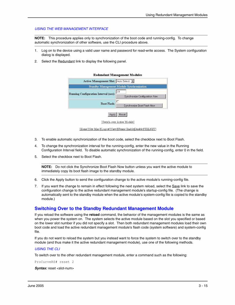
Using Redundant Management Modules
USING THE WEB MANAGEMENT INTERFACE
NOTE: This procedure applies only to synchronization of the boot code and running-config. To change automatic synchronization of other software, use the CLI procedure above.
1. Log on to the device using a valid user name and password for read-write access. The System configuration dialog is displayed.
2. Select the Redundant link to display the following panel.
3. To enable automatic synchronization of the boot code, select the checkbox next to Boot Flash.
4. To change the synchronization interval for the running-config, enter the new value in the Running Configuration Interval field. To disable automatic synchronization of the running-config, enter 0 in the field.
5. Select the checkbox next to Boot Flash.
NOTE: Do not click the Synchronize Boot Flash Now button unless you want the active module to immediately copy its boot flash image to the standby module.
6. Click the Apply button to send the configuration change to the active module’s running-config file.
7. If you want the change to remain in effect following the next system reload, select the Save link to save the configuration change to the active redundant management module's startup-config file. (The change is automatically sent to the standby module when the active module's system-config file is copied to the standby module.)
Switching Over to the Standby Redundant Management ModuleIf you reload the software using the reload command, the behavior of the management modules is the same as when you power the system on. The system selects the active module based on the slot you specified or based on the lower slot number if you did not specify a slot. Then both redundant management modules load their own boot code and load the active redundant management module's flash code (system software) and system-config file.
If you do not want to reload the system but you instead want to force the system to switch over to the standby module (and thus make it the active redundant management module), use one of the following methods.
USING THE CLI
To switch over to the other redundant management module, enter a command such as the following:
ProCurveRS# reset 2
Syntax: reset <slot-num>
June 2005 3 - 15
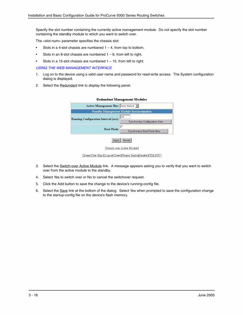
Installation and Basic Configuration Guide for ProCurve 9300 Series Routing Switches
Specify the slot number containing the currently active management module. Do not specify the slot number containing the standby module to which you want to switch over.
The <slot-num> parameter specifies the chassis slot:
• Slots in a 4-slot chassis are numbered 1 – 4, from top to bottom.
• Slots in an 8-slot chassis are numbered 1 – 8, from left to right.
• Slots in a 15-slot chassis are numbered 1 – 15, from left to right.
USING THE WEB MANAGEMENT INTERFACE
1. Log on to the device using a valid user name and password for read-write access. The System configuration dialog is displayed.
2. Select the Redundant link to display the following panel.
3. Select the Switch-over Active Module link. A message appears asking you to verify that you want to switch over from the active module to the standby.
4. Select Yes to switch over or No to cancel the switchover request.
5. Click the Add button to save the change to the device’s running-config file.
6. Select the Save link at the bottom of the dialog. Select Yes when prompted to save the configuration change to the startup-config file on the device’s flash memory.
3 - 16 June 2005
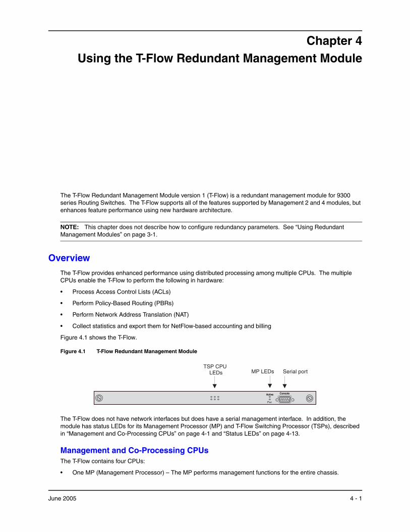
Chapter 4Using the T-Flow Redundant Management Module
The T-Flow Redundant Management Module version 1 (T-Flow) is a redundant management module for 9300 series Routing Switches. The T-Flow supports all of the features supported by Management 2 and 4 modules, but enhances feature performance using new hardware architecture.
NOTE: This chapter does not describe how to configure redundancy parameters. See “Using Redundant Management Modules” on page 3-1.
OverviewThe T-Flow provides enhanced performance using distributed processing among multiple CPUs. The multiple CPUs enable the T-Flow to perform the following in hardware:
• Process Access Control Lists (ACLs)
• Perform Policy-Based Routing (PBRs)
• Perform Network Address Translation (NAT)
• Collect statistics and export them for NetFlow-based accounting and billing
Figure 4.1 shows the T-Flow.
Figure 4.1 T-Flow Redundant Management Module
ConsoleActive
Pwr
TSP CPULEDs
ConsoleActive
Serial portMP LEDs
The T-Flow does not have network interfaces but does have a serial management interface. In addition, the module has status LEDs for its Management Processor (MP) and T-Flow Switching Processor (TSPs), described in “Management and Co-Processing CPUs” on page 4-1 and “Status LEDs” on page 4-13.
Management and Co-Processing CPUsThe T-Flow contains four CPUs:
• One MP (Management Processor) – The MP performs management functions for the entire chassis.
June 2005 4 - 1
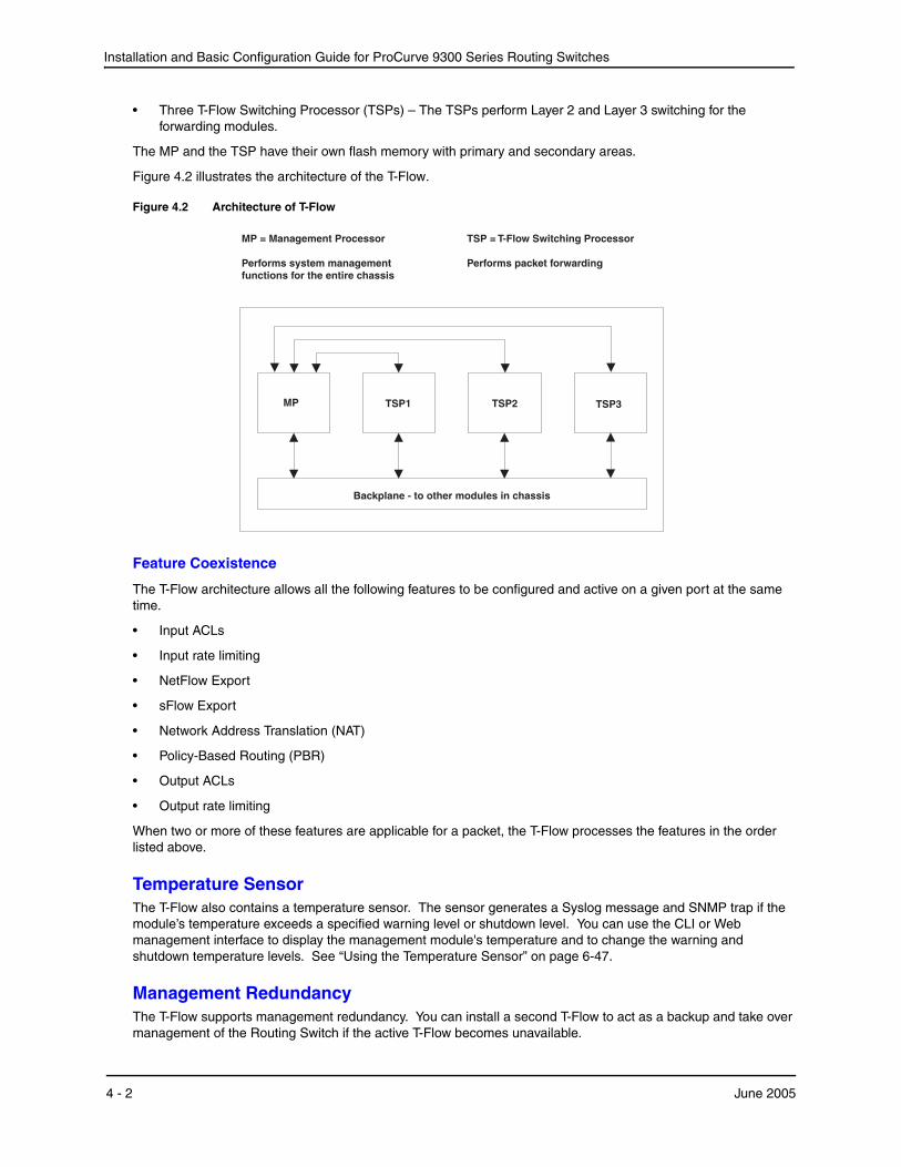
Installation and Basic Configuration Guide for ProCurve 9300 Series Routing Switches
• Three T-Flow Switching Processor (TSPs) – The TSPs perform Layer 2 and Layer 3 switching for the forwarding modules.
The MP and the TSP have their own flash memory with primary and secondary areas.
Figure 4.2 illustrates the architecture of the T-Flow.
Figure 4.2 Architecture of T-Flow
TSP2
Backplane - to other modules in chassis
TSP = T-Flow Switching Processor
Performs packet forwarding
TSP3MP TSP1
MP = Management Processor
Performs system managementfunctions for the entire chassis
Feature Coexistence
The T-Flow architecture allows all the following features to be configured and active on a given port at the same time.
• Input ACLs
• Input rate limiting
• NetFlow Export
• sFlow Export
• Network Address Translation (NAT)
• Policy-Based Routing (PBR)
• Output ACLs
• Output rate limiting
When two or more of these features are applicable for a packet, the T-Flow processes the features in the order listed above.
Temperature SensorThe T-Flow also contains a temperature sensor. The sensor generates a Syslog message and SNMP trap if the module’s temperature exceeds a specified warning level or shutdown level. You can use the CLI or Web management interface to display the management module's temperature and to change the warning and shutdown temperature levels. See “Using the Temperature Sensor” on page 6-47.
Management RedundancyThe T-Flow supports management redundancy. You can install a second T-Flow to act as a backup and take over management of the Routing Switch if the active T-Flow becomes unavailable.
4 - 2 June 2005
Using the T-Flow Redundant Management Module
Management redundancy is described in “Using Redundant Management Modules” on page 3-1. Management redundancy using a pair of T-Flow modules works as described in the chapter, with the following important differences:
• The TSP CPUs on both modules actively process traffic. Only the MP CPU on the standby module is in backup mode. The TSP CPUs on the standby module actively process traffic.
• The TSP CPU flash code is not automatically synchronized. To synchronize the flash code on the TSP CPUs, use the vm copy tftp flash command, described in “File Synchronization Between the Active and Standby Redundant Management Modules” on page 3-10. The flash code on the CPU is automatically synchronized.
• If you use a pair of T-Flow management modules in a chassis for redundancy, the device does not reassign the forwarding modules assigned to the TSP CPUs on the active module to the other module following a hot swap. See the next section.
Management Redundancy and Hot Swap
If you use a pair of T-Flow management modules in a chassis for redundancy, the device does not reassign the forwarding modules assigned to the TSP CPUs on the active module to the other module following a hot swap. This is true in the following cases:
• If you insert a standby T-Flow into an active device, the device does not replicate the assignments of the forwarding modules to the TSP CPUs on the standby module. To work around this issue, use the vm-map command to assign the forwarding modules to the TSP CPUs on the standby module after you insert the module.
• If you remove a standby T-Flow module that has taken over forwarding on an active device, the forwarding modules assigned to the TSP CPUs on the standby module are not reassigned to the TSP CPUs on the default active module. To avoid traffic interruption, use the vm-map command to assign the forwarding modules to the TSP CPUs on the default active T-Flow module before removing the standby module.
To list the TSP CPU assignments, enter the following command: show vm-map
To assign forwarding modules to TSP CPUs, enter the following command:
vm vm-map <from-slotnum> vm-slot <to-slotnum> vm-cpu <cpunum>
The <from-slotnum> parameter specifies the slot that contains the forwarding module.
The <to-slotnum> parameter specifies the slot that contains the T-Flow.
The <cpunum> parameter specifies the VSM CPU on <to-slotnum> that will perform the processing. The VSM CPUs are numbered from 1 – 3.
TSP Load SharingThe T-Flow optimizes performance by distributing responsibility for the forwarding modules across the TSPs, so that each TSP has sole responsibility for a given forwarding module and the modules are as evenly distributed across the TSPs in terms of bandwidth.
When you power on or reset the T-Flow, the module assigns each of the forwarding modules to a TSP according to each module’s weight. A forwarding module’s weight is a number that represents its total forwarding capacity. The weight is measured in units of 1 for each 100 Mbps. For example, Table 4.1 shows the weights for some common forwarding module types. Notice that the weight for 10/100 modules is based on the higher bandwidth (100 Mbps instead of 10 Mbps) for all ports.
June 2005 4 - 3
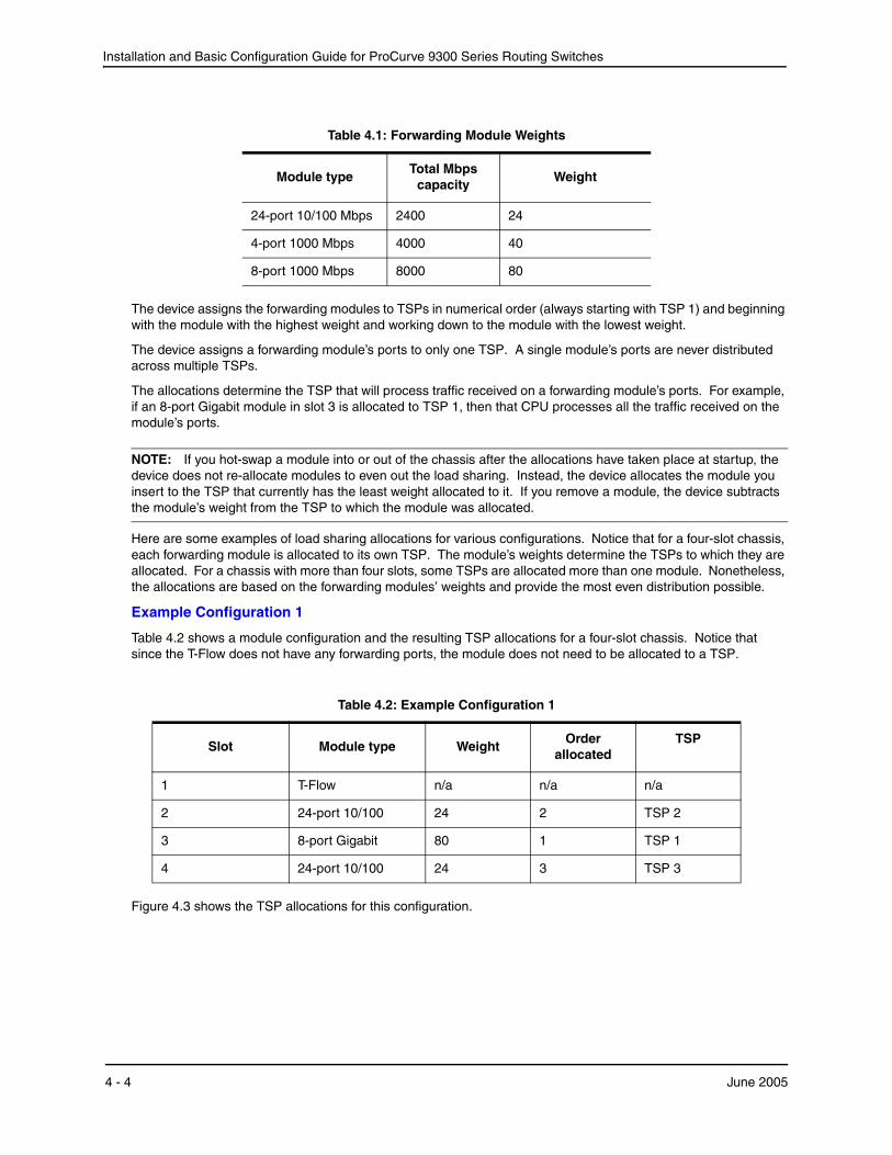
Installation and Basic Configuration Guide for ProCurve 9300 Series Routing Switches
Table 4.1: Forwarding Module Weights
Module typeTotal Mbps
capacityWeight
24-port 10/100 Mbps 2400 24
4-port 1000 Mbps 4000 40
8-port 1000 Mbps 8000 80
The device assigns the forwarding modules to TSPs in numerical order (always starting with TSP 1) and beginning with the module with the highest weight and working down to the module with the lowest weight.
The device assigns a forwarding module’s ports to only one TSP. A single module’s ports are never distributed across multiple TSPs.
The allocations determine the TSP that will process traffic received on a forwarding module’s ports. For example, if an 8-port Gigabit module in slot 3 is allocated to TSP 1, then that CPU processes all the traffic received on the module’s ports.
NOTE: If you hot-swap a module into or out of the chassis after the allocations have taken place at startup, the device does not re-allocate modules to even out the load sharing. Instead, the device allocates the module you insert to the TSP that currently has the least weight allocated to it. If you remove a module, the device subtracts the module’s weight from the TSP to which the module was allocated.
Here are some examples of load sharing allocations for various configurations. Notice that for a four-slot chassis, each forwarding module is allocated to its own TSP. The module’s weights determine the TSPs to which they are allocated. For a chassis with more than four slots, some TSPs are allocated more than one module. Nonetheless, the allocations are based on the forwarding modules’ weights and provide the most even distribution possible.
Example Configuration 1
Table 4.2 shows a module configuration and the resulting TSP allocations for a four-slot chassis. Notice that since the T-Flow does not have any forwarding ports, the module does not need to be allocated to a TSP.
Table 4.2: Example Configuration 1
Slot Module type WeightOrder
allocatedTSP
1 T-Flow n/a n/a n/a
2 24-port 10/100 24 2 TSP 2
3 8-port Gigabit 80 1 TSP 1
4 24-port 10/100 24 3 TSP 3
Figure 4.3 shows the TSP allocations for this configuration.
4 - 4 June 2005
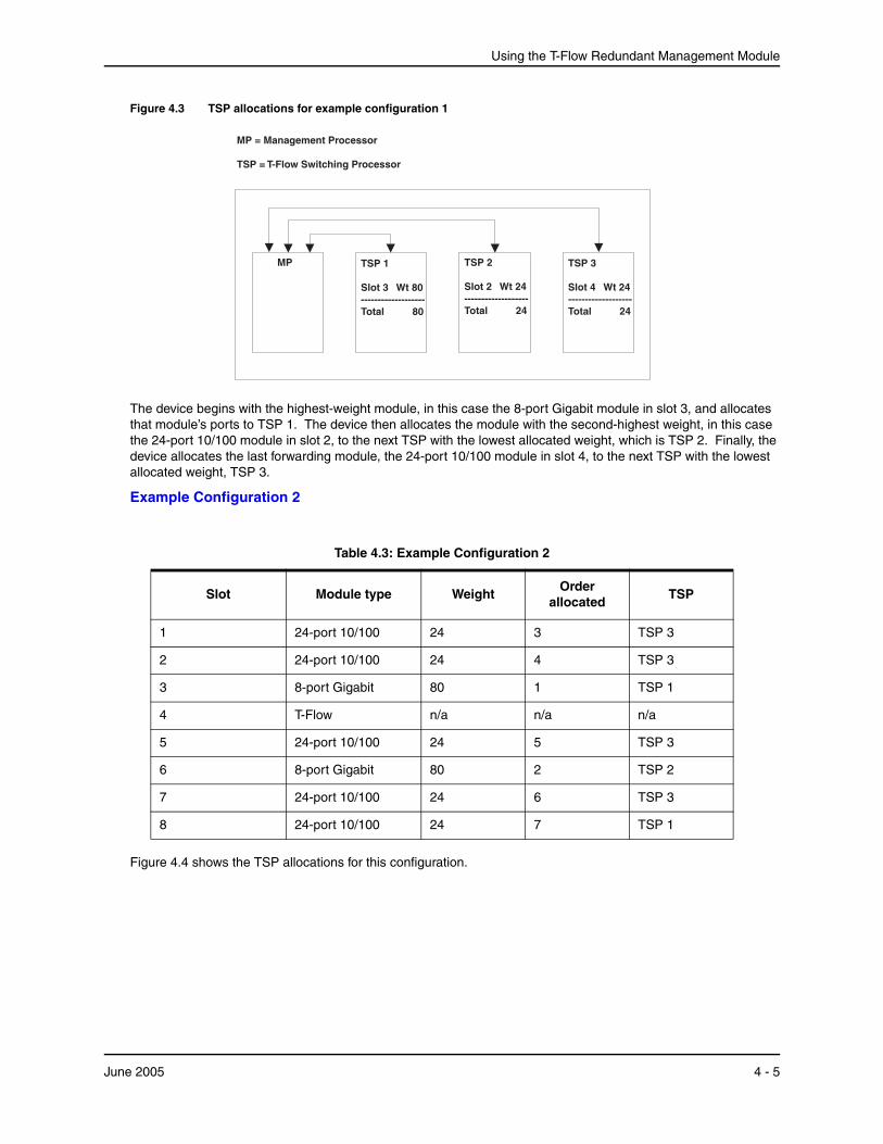
Using the T-Flow Redundant Management Module
Figure 4.3 TSP allocations for example configuration 1
TSP 2
Slot 2 Wt 24-------------------Total 24
TSP 3
Slot 4 Wt 24-------------------Total 24
MP TSP 1
Slot 3 Wt 80-------------------Total 80
MP = Management Processor
TSP = T-Flow Switching Processor
The device begins with the highest-weight module, in this case the 8-port Gigabit module in slot 3, and allocates that module’s ports to TSP 1. The device then allocates the module with the second-highest weight, in this case the 24-port 10/100 module in slot 2, to the next TSP with the lowest allocated weight, which is TSP 2. Finally, the device allocates the last forwarding module, the 24-port 10/100 module in slot 4, to the next TSP with the lowest allocated weight, TSP 3.
Example Configuration 2
Table 4.3: Example Configuration 2
Slot Module type WeightOrder
allocatedTSP
1 24-port 10/100 24 3 TSP 3
2 24-port 10/100 24 4 TSP 3
3 8-port Gigabit 80 1 TSP 1
4 T-Flow n/a n/a n/a
5 24-port 10/100 24 5 TSP 3
6 8-port Gigabit 80 2 TSP 2
7 24-port 10/100 24 6 TSP 3
8 24-port 10/100 24 7 TSP 1
Figure 4.4 shows the TSP allocations for this configuration.
June 2005 4 - 5
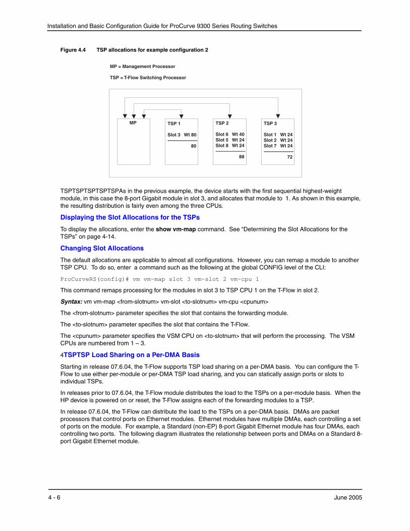
Installation and Basic Configuration Guide for ProCurve 9300 Series Routing Switches
Figure 4.4 TSP allocations for example configuration 2
TSP 2
Slot 6 Wt 40Slot 5 Wt 24Slot 8 Wt 24-------------------
88
TSP 3
Slot 1 Wt 24Slot 2 Wt 24Slot 7 Wt 24-------------------
72
MP TSP 1
Slot 3 Wt 80-------------------
80
MP = Management Processor
TSP = T-Flow Switching Processor
TSPTSPTSPTSPTSPAs in the previous example, the device starts with the first sequential highest-weight module, in this case the 8-port Gigabit module in slot 3, and allocates that module to 1. As shown in this example, the resulting distribution is fairly even among the three CPUs.
Displaying the Slot Allocations for the TSPs
To display the allocations, enter the show vm-map command. See “Determining the Slot Allocations for the TSPs” on page 4-14.
Changing Slot Allocations
The default allocations are applicable to almost all configurations. However, you can remap a module to another TSP CPU. To do so, enter a command such as the following at the global CONFIG level of the CLI:
ProCurveRS(config)# vm vm-map slot 3 vm-slot 2 vm-cpu 1
This command remaps processing for the modules in slot 3 to TSP CPU 1 on the T-Flow in slot 2.
Syntax: vm vm-map <from-slotnum> vm-slot <to-slotnum> vm-cpu <cpunum>
The <from-slotnum> parameter specifies the slot that contains the forwarding module.
The <to-slotnum> parameter specifies the slot that contains the T-Flow.
The <cpunum> parameter specifies the VSM CPU on <to-slotnum> that will perform the processing. The VSM CPUs are numbered from 1 – 3.
4TSPTSP Load Sharing on a Per-DMA Basis
Starting in release 07.6.04, the T-Flow supports TSP load sharing on a per-DMA basis. You can configure the T-Flow to use either per-module or per-DMA TSP load sharing, and you can statically assign ports or slots to individual TSPs.
In releases prior to 07.6.04, the T-Flow module distributes the load to the TSPs on a per-module basis. When the HP device is powered on or reset, the T-Flow assigns each of the forwarding modules to a TSP.
In release 07.6.04, the T-Flow can distribute the load to the TSPs on a per-DMA basis. DMAs are packet processors that control ports on Ethernet modules. Ethernet modules have multiple DMAs, each controlling a set of ports on the module. For example, a Standard (non-EP) 8-port Gigabit Ethernet module has four DMAs, each controlling two ports. The following diagram illustrates the relationship between ports and DMAs on a Standard 8-port Gigabit Ethernet module.
4 - 6 June 2005
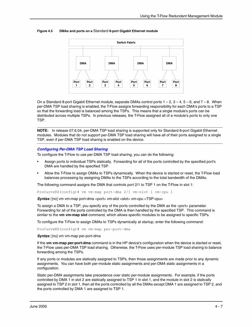
Using the T-Flow Redundant Management Module
Figure 4.5 DMAs and ports on a Standard 8-port Gigabit Ethernet module
DMA
Port7
Port8
DMA
Port5
Port6
DMA
Port3
Port4
DMA
Port1
Port2
Switch Fabric
On a Standard 8-port Gigabit Ethernet module, separate DMAs control ports 1 – 2, 3 – 4, 5 – 6, and 7 – 8. When per-DMA TSP load sharing is enabled, the T-Flow assigns forwarding responsibility for each DMA’s ports to a TSP so that the forwarding load is balanced among the TSPs. This means that a single module’s ports can be distributed across multiple TSPs. In previous releases, the T-Flow assigned all of a module’s ports to only one TSP.
NOTE: In release 07.6.04, per-DMA TSP load sharing is supported only for Standard 8-port Gigabit Ethernet modules. Modules that do not support per-DMA TSP load sharing will have all of their ports assigned to a single TSP, even if per-DMA TSP load sharing is enabled on the device.
Configuring Per-DMA TSP Load SharingTo configure the T-Flow to use per-DMA TSP load sharing, you can do the following:
• Assign ports to individual TSPs statically. Forwarding for all of the ports controlled by the specified port’s DMA are handled by the specified TSP.
• Allow the T-Flow to assign DMAs to TSPs dynamically. When the device is started or reset, the T-Flow load balances processing by assigning DMAs to the TSPs according to the total bandwidth of the DMAs.
The following command assigns the DMA that controls port 2/1 to TSP 1 on the T-Flow in slot 1:
ProCurveRS(config)# vm vm-map port-dma 2/1 vm-slot 1 vm-cpu 1
Syntax: [no] vm vm-map port-dma <port> vm-slot <slot> vm-cpu <TSP-cpu>
To assign a DMA to a TSP, you specify any of the ports controlled by the DMA as the <port> parameter. Forwarding for all of the ports controlled by the DMA is then handled by the specified TSP. This command is similar to the vm vm-map slot command, which allows specific modules to be assigned to specific TSPs.
To configure the T-Flow to assign DMAs to TSPs dynamically at startup, enter the following command:
ProCurveRS(config)# vm vm-map per-port-dma
Syntax: [no] vm vm-map per-port-dma
If the vm vm-map per-port-dma command is in the HP device’s configuration when the device is started or reset, the T-Flow uses per-DMA TSP load sharing. Otherwise, the T-Flow uses per-module TSP load sharing to balance forwarding among the TSPs.
If any ports or modules are statically assigned to TSPs, then those assignments are made prior to any dynamic assignments. You can have both per-module static assignments and per-DMA static assignments in a configuration.
Static per-DMA assignments take precedence over static per-module assignments. For example, if the ports controlled by DMA 1 in slot 2 are statically assigned to TSP 1 in slot 1, and the module in slot 2 is statically assigned to TSP 2 in slot 1, then all the ports controlled by all the DMAs except DMA 1 are assigned to TSP 2, and the ports controlled by DMA 1 are assigned to TSP 1.
June 2005 4 - 7
Installation and Basic Configuration Guide for ProCurve 9300 Series Routing Switches
Changing the Management Session from the MP to a TSPBy default, management sessions you open with the T-Flow are established with the MP. However, you can establish a session directly with a TSP. Each TSP supports some commands at the Privileged EXEC level.
NOTE: You can enter configuration commands only to the MP, not directly to a TSP.
The CLI provides a remote login facility for changing the management session to a TSP. When you log in to a TSP, the CLI management session changes from the MP to the TSP. At this point, commands apply only to the TSP. To enter commands to the MP, you must log out of the TSP. The CLI prompt changes to indicate the chassis slot number and TSP you are logged on to.
Logging In to a TSPTo log in to a TSP, enter a command such as the following at the Privileged EXEC level of the CLI:
ProCurveRS# rconsole 2 1 ProCurveRS2/1 #
This command changes the management session from the MP to TSP 1 on the T-Flow in slot 2. Notice that the end of the command prompt changes to indicate the slot number and TSP number.
Syntax: rconsole <slotnum> <cpunum>
The <slotnum> parameter specifies the chassis slot that contains the module.
• Slots in a four-slot chassis are numbered 1 – 4, from top to bottom.
• Slots in an eight-slot chassis are numbered 1 – 8, from left to right.
• Slots in a fifteen-slot chassis are numbered 1 – 15, from left to right.
The <cpunum> parameter specifies the TSP. The TSPs are numbered from 1 – 3.
Logging Out from the TSPTo log out from a management session with a TSP, enter the following command at the User EXEC or Privileged EXEC level:
ProCurveRS2/1 # rconsole-exit ProCurveRS#
Syntax: rconsole-exit
NOTE: You must enter the entire command name (rconsole-exit). The CLI will not accept abbreviated forms of the command.
TSP CommandsThe following commands are supported at the TSP command prompt:
• rconsole-exit – Logs out of the TSP.
• show ? – Displays the available show commands. The following show commands are available:
• show arp – Displays the ARP table.
• show filter – Displays configured filters.
• show ip access-lists – Shows the configured ACLs.
• show ip cache – Shows the IP cache.
• show ip nat – Shows NAT information.
• show ip route – Shows the IP route table.
4 - 8 June 2005
Using the T-Flow Redundant Management Module
• show mac-address – Shows the MAC table.
• show running-config – Shows the running-config.
• show usage – Shows Layer 4 session table information.
• show trunk – Shows trunk group information.
• show vlans – Shows VLAN information.
• write terminal – Displays the running-config on the management console.
With a few exceptions, the command syntax and displays are the same as described in the Command Line Interface Reference for ProCurve 9300/9400 Series Routing Switches. Here are the exceptions:
• The show ip route command displays only 20 entries at a time. The command has an optional parameter, <num>, that indicates the entry at which you want the display to begin.
• The output of the show trunk and show vlans commands is different from the output format for these commands when entered on the MP.
Displaying T-Flow Module InformationYou can display the following T-Flow information:
• Software versions – see “Displaying the Software Version Running on the Module” on page 4-9
• General module information – “Displaying General Module Information” on page 4-11
• Module status – see “Determining Module Status” on page 4-12
• Slot allocations for the TSPs – see “Determining the Slot Allocations for the TSPs” on page 4-14
The commands in this section are supported on the MP, not on the TSPs.
Displaying the Software Version Running on the ModuleTo display the software version running on the T-Flow, use either of the following methods.
June 2005 4 - 9
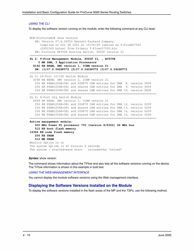
Installation and Basic Configuration Guide for ProCurve 9300 Series Routing Switches
USING THE CLI
To display the software version running on the module, enter the following command at any CLI level:
MON-ProCurveRS# show version SW: Version 07.6.04T53 Hewlett-Packard Company Compiled on Oct 28 2001 at 15:54:49 labeled as T-FlowR07500 (2852369 bytes) from Primary T-Flowr07500.bin HW: ProCurve HP9308 Routing Switch, SYSIF version 21 ========================================================================== SL 2: T-Flow Management Module, SYSIF II, , ACTIVE 0 MB SHM, 3 Application Processors 8192 KB BRAM, SMC version 1, ICBM version 21 SW: (1)07.6.042SPT72 (2)07.6.042SPT72 (3)07.6.042SPT72 ========================================================================== SL 3: 24-Port 10/100 Switch Module 2048 KB BRAM, SMC version 2, ICBM version 21 256 KB PRAM(256K+0K) and 2048*8 CAM entries for DMA 8, version 0808 256 KB PRAM(256K+0K) and shared CAM entries for DMA 9, version 0808 256 KB PRAM(256K+0K) and shared CAM entries for DMA 10, version 0808 ========================================================================== SL 4: 8-Port Gig Switch Module 2048 KB BRAM, SMC version 1, ICBM version 21 256 KB PRAM(256K+0K) and 2048*8 CAM entries for DMA 12, version 0209 256 KB PRAM(256K+0K) and shared CAM entries for DMA 13, version 0209 256 KB PRAM(256K+0K) and 2048*8 CAM entries for DMA 14, version 0209 256 KB PRAM(256K+0K) and shared CAM entries for DMA 15, version 0209 ========================================================================== Active management module: 500 MHz Power PC processor 750 (version 8/8302) 66 MHz bus 512 KB boot flash memory 16384 KB code flash memory 256 KB SRAM 512 MB DRAM Monitor Option is on The system uptime is 42 minutes 6 seconds The system : started=warm start reloaded=by "reload"
Syntax: show version
The command shows information about the T-Flow and also lists all the software versions running on the device. The T-Flow information is shown in this example in bold text.
USING THE WEB MANAGEMENT INTERFACE
You cannot display the module software versions using the Web management interface.
Displaying the Software Versions Installed on the ModuleTo display the software versions installed in the flash areas of the MP and the TSPs, use the following method.
4 - 10 June 2005
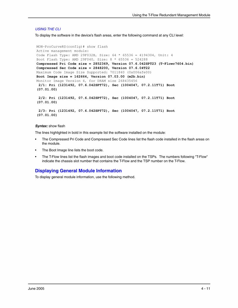
Using the T-Flow Redundant Management Module
USING THE CLI
To display the software in the device’s flash areas, enter the following command at any CLI level:
MON-ProCurveRS(config)# show flash Active management module: Code Flash Type: AMD 29F032B, Size: 64 * 65536 = 4194304, Unit: 4 Boot Flash Type: AMD 29F040, Size: 8 * 65536 = 524288 Compressed Pri Code size = 2852369, Version 07.6.042SPT23 (T-Flowr7604.bin) Compressed Sec Code size = 2848200, Version 07.6.04T22 Maximum Code Image Size Supported: 7011840 (0x006afe00) Boot Image size = 162664, Version 07.03.00 (m2b.bin) Monitor Image Version 4, for DRAM size 268435456 2/1: Pri (1231492, 07.6.042SPT72), Sec (1004047, 07.2.11T71) Boot (07.01.00) 2/2: Pri (1231492, 07.6.042SPT72), Sec (1004047, 07.2.11T71) Boot (07.01.00) 2/3: Pri (1231492, 07.6.042SPT72), Sec (1004047, 07.2.11T71) Boot (07.01.00)
Syntax: show flash
The lines highlighted in bold in this example list the software installed on the module:
• The Compressed Pri Code and Compressed Sec Code lines list the flash code installed in the flash areas on the module.
• The Boot Image line lists the boot code.
• The T-Flow lines list the flash images and boot code installed on the TSPs. The numbers following "T-Flow" indicate the chassis slot number that contains the T-Flow and the TSP number on the T-Flow.
Displaying General Module InformationTo display general module information, use the following method.
June 2005 4 - 11
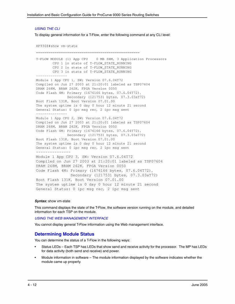
Installation and Basic Configuration Guide for ProCurve 9300 Series Routing Switches
USING THE CLI
To display general information for a T-Flow, enter the following command at any CLI level:
HP9308#show vm-state
==================================================
T-FLOW MODULE (1) App CPU 0 MB SHM, 3 Application Processors CPU 1 in state of T-FLOW_STATE_RUNNING CPU 2 in state of T-FLOW_STATE_RUNNING CPU 3 in state of T-FLOW_STATE_RUNNING --------------- Module 1 App CPU 1, SW: Version 07.6.04T72 Compiled on Jun 27 2003 at 21:20:01 labeled as TSP07604 DRAM 268M, BRAM 262K, FPGA Version 0050 Code Flash 4M: Primary (1676166 bytes, 07.6.04T72), Secondary (1217531 bytes, 07.3.03aT72) Boot Flash 131K, Boot Version 07.01.00 The system uptime is 0 day 0 hour 12 minute 21 second General Status: 0 ipc msg rec, 2 ipc msg sent --------------- Module 1 App CPU 2, SW: Version 07.6.04T72 Compiled on Jun 27 2003 at 21:20:01 labeled as TSP07604 DRAM 268M, BRAM 262K, FPGA Version 0050 Code Flash 4M: Primary (1676166 bytes, 07.6.04T72), Secondary (1217531 bytes, 07.3.03aT72) Boot Flash 131K, Boot Version 07.01.00 The system uptime is 0 day 0 hour 12 minute 21 second General Status: 0 ipc msg rec, 2 ipc msg sent --------------- Module 1 App CPU 3, SW: Version 07.6.04T72 Compiled on Jun 27 2003 at 21:20:01 labeled as TSP07604 DRAM 268M, BRAM 262K, FPGA Version 0050 Code Flash 4M: Primary (1676166 bytes, 07.6.04T72), Secondary (1217531 bytes, 07.3.03aT72) Boot Flash 131K, Boot Version 07.01.00 The system uptime is 0 day 0 hour 12 minute 21 second General Status: 0 ipc msg rec, 2 ipc msg sent
Syntax: show vm-state
This command displays the state of the T-Flow, the software version running on the module, and detailed information for each TSP on the module.
USING THE WEB MANAGEMENT INTERFACE
You cannot display general T-Flow information using the Web management interface.
Determining Module StatusYou can determine the status of a T-Flow in the following ways:
• Status LEDs – Each TSP has LEDs that show send and receive activity for the processor. The MP has LEDs for data activity (both send and receive) and power.
• Module information in software – The module information displayed by the software indicates whether the module came up properly.
4 - 12 June 2005
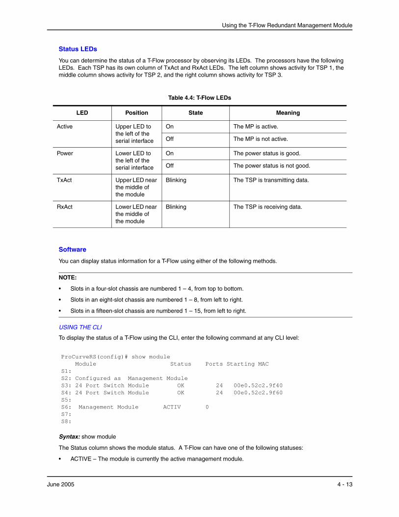
Using the T-Flow Redundant Management Module
Status LEDs
You can determine the status of a T-Flow processor by observing its LEDs. The processors have the following LEDs. Each TSP has its own column of TxAct and RxAct LEDs. The left column shows activity for TSP 1, the middle column shows activity for TSP 2, and the right column shows activity for TSP 3.
Table 4.4: T-Flow LEDs
LED Position State Meaning
Active Upper LED to the left of the serial interface
On The MP is active.
Off The MP is not active.
Power Lower LED to the left of the serial interface
On The power status is good.
Off The power status is not good.
TxAct Upper LED near the middle of the module
Blinking The TSP is transmitting data.
RxAct Lower LED near the middle of the module
Blinking The TSP is receiving data.
Software
You can display status information for a T-Flow using either of the following methods.
NOTE:
• Slots in a four-slot chassis are numbered 1 – 4, from top to bottom.
• Slots in an eight-slot chassis are numbered 1 – 8, from left to right.
• Slots in a fifteen-slot chassis are numbered 1 – 15, from left to right.
USING THE CLI
To display the status of a T-Flow using the CLI, enter the following command at any CLI level:
ProCurveRS(config)# show module Module Status Ports Starting MAC S1: S2: Configured as Management Module S3: 24 Port Switch Module OK 24 00e0.52c2.9f40 S4: 24 Port Switch Module OK 24 00e0.52c2.9f60 S5: S6: Management Module ACTIV 0 S7: S8:
Syntax: show module
The Status column shows the module status. A T-Flow can have one of the following statuses:
• ACTIVE – The module is currently the active management module.
June 2005 4 - 13
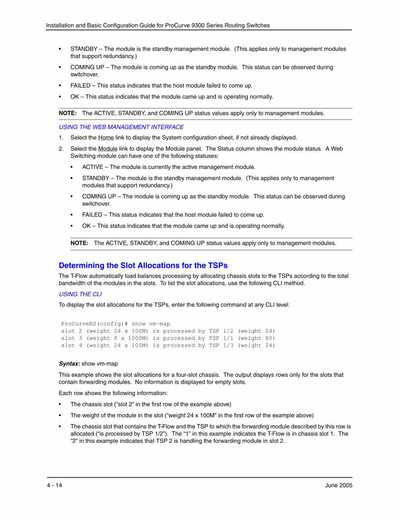
Installation and Basic Configuration Guide for ProCurve 9300 Series Routing Switches
• STANDBY – The module is the standby management module. (This applies only to management modules that support redundancy.)
• COMING UP – The module is coming up as the standby module. This status can be observed during switchover.
• FAILED – This status indicates that the host module failed to come up.
• OK – This status indicates that the module came up and is operating normally.
NOTE: The ACTIVE, STANDBY, and COMING UP status values apply only to management modules.
USING THE WEB MANAGEMENT INTERFACE
1. Select the Home link to display the System configuration sheet, if not already displayed.
2. Select the Module link to display the Module panel. The Status column shows the module status. A Web Switching module can have one of the following statuses:
• ACTIVE – The module is currently the active management module.
• STANDBY – The module is the standby management module. (This applies only to management modules that support redundancy.)
• COMING UP – The module is coming up as the standby module. This status can be observed during switchover.
• FAILED – This status indicates that the host module failed to come up.
• OK – This status indicates that the module came up and is operating normally.
NOTE: The ACTIVE, STANDBY, and COMING UP status values apply only to management modules.
Determining the Slot Allocations for the TSPsThe T-Flow automatically load balances processing by allocating chassis slots to the TSPs according to the total bandwidth of the modules in the slots. To list the slot allocations, use the following CLI method.
USING THE CLI
To display the slot allocations for the TSPs, enter the following command at any CLI level:
ProCurveRS(config)# show vm-map slot 2 (weight 24 x 100M) is processed by TSP 1/2 (weight 24) slot 3 (weight 8 x 1000M) is processed by TSP 1/1 (weight 80) slot 4 (weight 24 x 100M) is processed by TSP 1/3 (weight 24)
Syntax: show vm-map
This example shows the slot allocations for a four-slot chassis. The output displays rows only for the slots that contain forwarding modules. No information is displayed for empty slots.
Each row shows the following information:
• The chassis slot (“slot 2” in the first row of the example above)
• The weight of the module in the slot (“weight 24 x 100M” in the first row of the example above)
• The chassis slot that contains the T-Flow and the TSP to which the forwarding module described by this row is allocated (“is processed by TSP 1/2”). The “1” in this example indicates the T-Flow is in chassis slot 1. The “2” in this example indicates that TSP 2 is handling the forwarding module in slot 2.
4 - 14 June 2005

Using the T-Flow Redundant Management Module
• The total weight assigned to the TSP (“weight 24“ in the first row of this example).
NOTE: If the ports on a module are not up, the output says "will be processed" instead of "is processed" and the weight is listed as "0". In this case, the T-Flow reserves a TSP for the module but does not add weight for the module’s ports to the reserved TSP.
NOTE: For reference, this example matches “Example Configuration 1” on page 4-4.
When per-DMA TSP load sharing is enabled on the device, the show vm-map command displays static TSP assignments. For example:
ProCurveRS# show vm-map slot 1 (weight 80 x 100M): e 1/5-1/6 is processed by TSP processor 4/2 e 1/7-1/8 is processed by TSP processor 4/3 slot 2 (weight 24 x 100M) is processed by TSP processor 4/1 Static configuration: slot 1 (weight 80 x 100M): e 1/1-1/2 is processed by TSP processor 4/3 e 1/3-1/4 is processed by TSP processor 4/1
In the example above, per-DMA TSP load sharing has been enabled on the device. The module in slot 1 supports per-DMA TSP load sharing, but the module in slot 2 does not. The T-Flow is located in slot 4.
On the module in slot 1, the DMAs controlling ports 1 – 2 and 3 – 4 have been statically assigned to TSPs. The DMAs controlling the other ports on the module have been dynamically assigned to TSPs based on the weight of the DMAs.
All of the ports on the module in slot 2 are assigned to TSP 4/1. Since the module does not support per-DMA TSP load sharing, all of its ports are assigned to a single TSP.
June 2005 4 - 15

Installation and Basic Configuration Guide for ProCurve 9300 Series Routing Switches
4 - 16 June 2005
Chapter 5Using the 2-Port 10-Gigabit Ethernet Module
NOTE: For information on installing or removing either a 10-Gigabit Ethernet module or the XENPAK optics used with the J8174A 2-port 10-Gigabit Ethernet module, refer to any of the following:
• Chapter 2, “Installation” on page 2-1
• Quick Start Guide for ProCurve 9300 Series Routing Switches (included with 9300M series chassis models).
• Removing and Installing XENPAK Optics, an instruction sheet included in the Documentation CD shipped with HP ProCurve Series 9300 modules
HP periodically updates the Routing Switch 9300M series documentation. You can download the latest version of the documentation for your Routing Switch by visiting the HP Procurve website at:
http://www.procurve.com
Click on technical support, then product manuals.
This chapter describes the HP 2-port 10-Gigabit Ethernet modules. It contains the following topics:
• “1-Port 10 Gigabit Ethernet Module (Discontinued)” below
• “2-Port 10-Gigabit Ethernet Modules with XENPAK Optics” on page 5-2
• “Cleaning the Fiber Optic Connectors” on page 5-3
• “Cabling 10 Gigabit Ethernet Modules” on page 5-3
• “Port LEDs” on page 5-4
• “Troubleshooting Network Connections” on page 5-4
• “Upgrading an FPGA on a 10 Gigabit Ethernet Module” on page 5-8
1-Port 10 Gigabit Ethernet Module (Discontinued) The 1-port 10 Gigabit Ethernet module provides the following types of 10 Gigabit Ethernet interfaces:
• 1310nm serial for single-mode fiber – part number J4891A
Figure 5.1 shows the front panel of a 1-port 10 Gigabit Ethernet module.
June 2005 5 - 1
Installation and Basic Configuration Guide for ProCurve 9300 Series Routing Switches
Figure 5.1 Front panel of 1-port 10 Gigabit Ethernet module
Link
Activity
1
This module provides one 10 Gigabit interface. The interfaces operate at full duplex. For the serial port types listed above, use the matching fiber type with an SC connector. For example, if you are using the 1310nm serial module for single-mode fiber, attach a 1310nm single-mode fiber cable that has an SC connector.
HP 10 Gigabit Ethernet modules are compliant with the IEEE 802.3ae 10-Gigabit Ethernet standard.
System RequirementsThe 1-port 10 Gigabit Ethernet modules are supported in the following products:
• 9304M, 9308M, and 9315M
• All M2 and M4 management modules, including the J4885A EP mini-GBIC management module. (M1 management modules do not support the 1-port 10 Gigabit module.)
Hardware on the 1-Port 10 Gigabit Ethernet ModuleEach 1-port 10 Gigabit Ethernet module uses a single 10 Gigabit Ethernet MAC controller, separate transmit and receive controllers, and five Field-Programmable Gate Arrays (FPGAs). The FPGAs enable you to easily implement architecture upgrades without changing the hardware. The software includes a CLI command you can use to upgrade the FPGAs if needed. See “Upgrading an FPGA on a 10 Gigabit Ethernet Module” on page 5-8.
The 10 Gigabit Ethernet standard does not include link auto-negotiation. An HP 10 Gigabit Ethernet port is unable to detect a link failure at the other end of the link if the failure is on the receive side of the remote link. However, the HP 10 Gigabit Ethernet port can detect a link failure if the failure occurs on the transmit side of the remote link.
NOTE: The non-XENPAK 10 Gigabit Ethernet module can function in the same chassis with HP’s XENPAK-based 2-Port 10-Gigabit Ethernet modules.
Features Not Supported on the 1-Port 10 Gigabit Ethernet ModuleThe following features are not supported on the non-XENPAK 10 Gigabit Ethernet module in the current release:
• Rate limiting
• QoS
• IP multicast on tagged ports
• Jumbo packets, if the module is used in a chassis that contains Standard (non-EP) modules. When you use the module in a chassis containing EP modules, jumbo packets are supported.
Replacing the Optics on the 1-Port 10 Gigabit Ethernet ModuleIf you need to replace the optics on the non-XENPAK 10 Gigabit Ethernet module, contact Hewlett-Packard.
2-Port 10-Gigabit Ethernet Modules with XENPAK OpticsSoftware release 07.6.04 introduced support for the J8174A 2-port 10-Gigabit Ethernet module with XENPAK optics.
Figure 5.2 shows the front panel of a 2-port 10 Gigabit Ethernet Module.
5 - 2 June 2005
Using the 2-Port 10-Gigabit Ethernet Module
Figure 5.2 Front panel of 2-port 10 Gigabit Ethernet module
Link
Activity1
TX RXLink
Activity2
TX RX
10G
E
2-port
The 10 Gigabit Ethernet interfaces operate at full duplex. The module uses GBIC-like XENPAK Multisource Agreement (MSA) optics. The XENPAK optics are hot-swappable, allowing you to change the optics without removing the module from the chassis.
System RequirementsThe XENPAK-based J8174A 2-port 10 Gigabit Ethernet module is supported in the 9304M, 9308M, and 9315M.
Hardware on the XENPAK-Based 10 Gigabit Ethernet ModuleEach port on the XENPAK-based 10 Gigabit Ethernet modules has a 10 Gigabit Ethernet MAC controller and separate transmit and receive controllers. The modules have two kinds of FPGAs. The FPGAs enable you to easily implement architecture upgrades without changing the hardware. The software includes a CLI command you can use to upgrade the FPGAs if needed. See “Upgrading an FPGA on a 10 Gigabit Ethernet Module” on page 5-8.
NOTE: The XENPAK-based 10 Gigabit Ethernet modules can function in the same chassis with the non-XENPAK-based 1-port 10 Gigabit Ethernet modules.
Features Not Supported on XENPAK-based 10 Gigabit Ethernet ModulesThe XENPAK-based 10 Gigabit Ethernet modules support all of the applicable Layer 2 and Layer 3 features in software release 07.6.04 and earlier. The following features are not supported in the current release:
• Rate limiting
• Jumbo packets, if the module is used in a chassis that contains Standard (non-EP) modules. When you use the module in a chassis containing EP modules, jumbo packets are supported.
Cleaning the Fiber Optic ConnectorsTo avoid problems with the connection between the fiber-optic module connectors and the fiber cable connectors, HP strongly recommends cleaning both connectors each time you disconnect and reconnect them. In particular, dust can accumulate in the connectors and cause problems such as reducing the optic launch power.
To clean the fiber cable connectors, HP recommends using a fiber-optic reel-type cleaner. You can purchase this type of cleaner from the following Web site:
http://www.fisfiber.com/fisfiber.com/Home_Page.asp
To clean the fiber-optic module connectors, HP recommends using a product that dispenses dust-free air, such as Micro-Blast. You can purchase such a product from the following Web site:
http://www.microcare.com/product/solvents/PS-50.html.
When cleaning a fiber-optic module connector, do not use unfiltered air from an air compressor, cotton swabs, or other types of swab applicators. These types of products may leave lint or dust in the connector.
Also, when not using a fiber-optic module connector, make sure to keep the protective covering on.
Cabling 10 Gigabit Ethernet ModulesTo cable a 10 Gigabit Ethernet module, do the following:
1. Remove the protective covering from the fiber-optic port connectors and store the covering for future use.
June 2005 5 - 3
Installation and Basic Configuration Guide for ProCurve 9300 Series Routing Switches
2. Before attaching cables to the module, HP strongly recommends cleaning the cable connectors and the port connectors. For more information, see “Cleaning the Fiber Optic Connectors”.
3. Gently insert the two cable connectors (a tab on each connector should face upward) into the port connectors until the tabs lock into place.
4. Observe the link and active LEDs to determine if the network connections are functioning properly. For more information about the LED indicators, see Table 5.1.
Port LEDsThe LEDs listed in Table 5.1 provide status information for 10 Gigabit Ethernet ports. All types of HP 10 Gigabit Ethernet modules use the same port LEDs.
Table 5.1: LEDs for 10 Gigabit Ethernet Ports
LED Position State Meaning
Link Top On Port is connected.
Off No port connection exists.
Activity Bottom On Traffic is being transmitted and received on that port.
Off No traffic is being transmitted.
Blinking Traffic is being transmitted and received on that port.
Troubleshooting Network ConnectionsAfter you attach cables to the 10 Gigabit Ethernet modules, you can observe the LEDs to determine if the network connections are functioning properly. Table 5.2 outlines possible abnormal states of each LED, and what to do if an LED indicates an abnormal state.
5 - 4 June 2005
Using the 2-Port 10-Gigabit Ethernet Module
Table 5.2: Network Connection-Related LED States
LED Abnormal State
Meaning/Action
Link Off A link is not established with the remote port. You can do the following:
• Verify that the connection to the other network device has been properly made. Also, make certain that the other network device is powered on and operating correctly.
• Verify that the transmit port on the HP device is connected to the receive port on the other network device, and that the receive port on the HP device is connected to the transmit port on the other network device. If you are not certain, remove the two cable connectors from the port connector and reinsert them in the port connector, reversing their order.
• Dust may have accumulated in the cable connector or port connector. For information about cleaning the connectors, see “Cleaning the Fiber Optic Connectors” on page 5-3.
• If the other actions don’t resolve the problem, try using a different port or a different cable.
Activity Off for an extended period.
The port is not transmitting or receiving user packets. You can do the following:
• Check the Link LED to make sure the link is still established with the remote port. If not, take the actions described in the Meaning/Action column for the Link LED.
• Verify that the port has not been disabled through a configuration change. You can use the CLI to do this. If you have configured an IP address on the device, you also can use the Web management interface .
If a problem persists after taking these actions, contact HP Technical Support.
Link Fault Signaling (LFS)
NOTE: This feature is supported in software releases 07.6.02 and later.
Link Fault Signalling (LFS) is a physical layer protocol that enables communication on a link between two 10 Gigabit Ethernet devices. When configured on an HP 10 Gigabit Ethernet port, the port can detect and report fault conditions on transmit and receive ports.
HP’s 10 Gigabit Ethernet devices include the following:
• First generation device:
• 1-port 10 Gigabit Ethernet Module
• Second generation devices:
• 2-port 10 Gigabit Ethernet Module with XENPAK optics
HP introduced LFS in software release 07.6.02, thereby enabling HP’s 10 Gigabit Ethernet devices to communicate critical link status information.
June 2005 5 - 5
Installation and Basic Configuration Guide for ProCurve 9300 Series Routing Switches
In release 07.6.03, HP’s implementation of LFS became compliant with the IEEE standard, however, you could enable it only between two First generation 10 Gigabit Ethernet devices, or between two Second generation 10 Gigabit Ethernet devices. LFS support was not available between First generation and Second generation 10 Gigabit Ethernet devices.
In software release 07.6.04 and later, HP’s software supports LFS among all 10 Gigabit Ethernet devices, including LFS support between First and Second generation devices.
Determining the 10 Gigabit Ethernet Module Installed in Your SystemTo determine which 10 Gigabit Ethernet Module your system is running, enter the show flash command at the Privileged EXEC level of the CLI. The output of the show flash command will help you determine which module is installed, as follows:
• First generation devices (1-port 10 Gigabit Ethernet Modules) will show five FPGA images.
• Second generation devices (2-port 10 Gigabit Ethernet Modules with XENPAK optics) will display two FPGA images.
Configuring Link Fault SignallingConfiguration procedures for LFS differ depending on your 10 Gigabit Ethernet hardware configuration. See “Determining the 10 Gigabit Ethernet Module Installed in Your System” on page 5-6.
To configure LFS, follow the appropriate procedures, below.
Enabling LFS Between Two First Generation Devices or Between Two Second Generation Devices
To enable LFS between two First generation 10 Gigabit Ethernet devices, or between two Second generation 10 Gigabit Ethernet devices, enter commands such as the following on both ends of the link:
ProCurveRS(config)# interface e 1/1 ProCurveRS(config-if-e1000-1/1)# link-fault-signal
Syntax: [no] link-fault-signal
Use the no form of the command to disable LFS.
LFS is OFF by default.
Enabling LFS Between a First Generation Device and a Second Generation Device
To enable LFS between a First generation 10 Gigabit Ethernet device and a Second generation 10 Gigabit Ethernet device, enter commands such as the following:
1. On the First generation 10 Gigabit Ethernet device, enter commands such as the following:
ProCurveRS(config)# interface e 1/1 ProCurveRS(config-if-e1000-1/1)# link-fault-signal
2. On the Second generation 10 Gigabit Ethernet device, enter commands such as the following:
ProCurveRS(config)# interface e 1/1 ProCurveRS(config-if-e1000-1/1)# link-fault-signal legacy
Syntax: [no] link-fault-signal legacy
Use the no form of the command to disable LFS.
LFS is OFF by default.
Remote Fault Notification (RFN) on Fiber ConnectionsFor fiber-optic connections, you can optionally configure a transmit port to notify the receive port on the remote device whenever the transmit port becomes disabled.
5 - 6 June 2005
Using the 2-Port 10-Gigabit Ethernet Module
When you enable this feature, the transmit port notifies the remote port whenever the fiber cable is either physically disconnected or has failed. When this occurs and the feature is enabled, the device disables the link and turns OFF both LEDs associated with the ports.
By default, Remote Fault Notification (RFN) is disabled. In this case, if the transmit port becomes physically disabled or fails, the link still appears as though it is enabled and the LEDs for both ports remain ON.
Configuration Notes• RFN is supported in software releases 07.6.05 and later.
• This feature is only available for Gigabit Ethernet Fiber ports. It is not available for 10/100 ports and Gigabit Ethernet Copper ports.
RFN Enhancements in 07.8.00Software releases prior to 07.8.00 provide support for Remote Fault Notification (RFN) on individual interfaces only.
Software release 07.8.00 provides enhanced support for RFN by making it available:
• Globally, on the entire device
• On a trunk group
• On an individual interface
Configuration Considerations
• Configuring RFN on a global basis enables RFN on every port and takes precedence over RFN configurations on trunk groups and on individual interfaces.
• When RFN is enabled both globally and on a trunk group, and you remove a secondary port in a trunk group, the secondary port becomes disabled and the primary port in the trunk group remains enabled.
• When RFN is enabled both globally and on a trunk group, the trunk group behaves as follows:
• If a primary port in a trunk group fails, only the primary port reports an RFN error. None of the other (secondary) ports in the trunk group will report an RFN error.
• If a secondary port in a trunk group fails, the secondary port reports an RFN error even though the primary port has not failed and is still enabled.
• When RFN is not enabled globally, but is enabled on a trunk group, the trunk group behaves as follows:
• If the primary port in a trunk group fails, the primary port will report an error. All other trunk ports will not report errors and will remain enabled.
• If a secondary port in a trunk group fails and the primary port is still enabled and has not failed, the secondary trunk port will report an error and all other trunk ports will remain enabled.
Enabling Remote Fault NotificationTo enable RFN globally, on the entire device, enter the following command:
ProCurveRS(config)# gig-default auto-gig rfn
To enable RFN on a trunk group, enter the command on the primary port of the trunk group, as shown in the following example:
ProCurveRS(config)# int e 1/1 ProCurveRS(config-if-e1000-1/1)# gig-default auto-gig rfn
To enable RFN on an individual interface, enter commands such as the following:
ProCurveRS(config)# int e 1/2 ProCurveRS(config-if-e1000-1/2)# gig-default auto-gig rfn
Syntax: [no] gig-default auto-gig rfn
June 2005 5 - 7
Installation and Basic Configuration Guide for ProCurve 9300 Series Routing Switches
To disable RFN after enabling it, use the no parameter with the command.
Viewing Which Fiber Ports Have RFN EnabledUse the show run command to view which fiber ports have RFN enabled. The following shows an example output.
ProCurveRS Router# sh run
Building configuration... Current configuration : 349 bytes ver 07.7.00b1T51
module 1 jc-8-port-gig-m4-management-module module 2 jc-16-port-gig-fiber-module module 3 jc-8-port-gig-module module 8 jc-16-port-gig-copper-module
no global-stp
no spanning-tree
ip address 2.2.2.2 255.255.255.255
auto-cam-repaint
pram-write-retry
interface ethernet 1/2
gig-default auto-gig rfn
Upgrading an FPGA on a 10 Gigabit Ethernet Module
NOTE: If an upgrade is required for any of the FPGA files, you must upgrade all the FPGA files.
1. Complete the upgrades of the boot code and flash code, if required.
2. Enter commands such as the following at the Privileged EXEC level of the CLI for the J4891A 1-port 10-Gigabit module:
ProCurveRS# 10gig copy tftp flash 10.10.10.10 rxbmgr.bin ProCurveRS# 10gig copy tftp flash 10.10.10.10 rxpp.bin ProCurveRS# 10gig copy tftp flash 10.10.10.10 txaccum.bin ProCurveRS# 10gig copy tftp flash 10.10.10.10 txpp.bin ProCurveRS# 10gig copy tftp flash 10.10.10.10 ageram.bin
For the J8174A 2-port 10-Gigabit module, enter:
ProCurveRS# 10gig copy tftp flash 10.10.10.10 xpp.bin ProCurveRS# 10gig copy tftp flash 10.10.10.10 xtm.bin
Syntax: 10gig copy tftp flash <ip-addr> <filename> [module <slotnum>]
where:
• tftp – The tftp parameter indicates that the file is on a TFTP server.
• <ip-addr> – specifies the IP address of the TFTP server, if you specify tftp.
• <filename> – specifies the FPGA file name.
5 - 8 June 2005
Using the 2-Port 10-Gigabit Ethernet Module
NOTE: You can store and copy the FPGA files using any valid filename; however, HP recommends that you use the file names listed in the “Software Image Files” section of the release notes. The device uses information within the files to install them in the correct FPGAs. The show flash command lists the FPGAs. For an example of the show flash output, see “Displaying the Installed FPGA Revisions” on page 5-9.
• module <slotnum> – optionally, specifies the modules on which you want to install the upgrade. If you do not specify a slot number, the command upgrades the FPGA on all 10 Gigabit Ethernet modules in the chassis.
3. Reload the software by entering one of the following commands:
• reload (this command boots from the default boot source, which is the primary flash area by default)
• boot system flash primary | secondary
NOTE: The show flash command will list the new FPGA code versions but the new versions do not take effect until you reload the software.
Displaying the Installed FPGA RevisionsTo display the software versions installed in flash memory on the management module and the FPGA versions installed on the 10 Gigabit Ethernet modules, enter the following command:
ProCurveRS# show flash Active management module: Code Flash Type: AMD 29LV033C, Size: 64 * 65536 = 4194304, Unit: 4 Boot Flash Type: AMD 29LV040B, Size: 8 * 65536 = 524288 Compressed Pri Code size = 2813111, Version 07.6.04b130T53 (h2r07603b130.bin) Compressed Sec Code size = 2799367, Version 07.6.04b79T53 (h2r07603b79.bin) Maximum Code Image Size Supported: 6815232 (0x0067fe00) Boot Image size = 275128, Version 07.06.04 (m2b07602.bin) Monitor Image Version 4, for DRAM size 268435456 Used Configuration Flash Size=2092, Max Configuration Flash Size=524288. 10 GIG module slot 2 X10G RXBMGR FGPA version: 80 revision: 6 2001/11/15 15:38:43 X10G RXPP FGPA version: 81 revision: 13 2002/06/17 17:28:53 X10G TXACCUM FGPA version: 82 revision: 6 2001/12/12 18:51:43 X10G TXPP FGPA version: 83 revision: 11 2002/08/16 19:15:36 X10G AGERAM FGPA version: 84 revision: 4 2001/10/26 19:53:24 2x10 GIG module slot 3 2X10G XTM FGPA version: 89 revision: 34 2003/02/07 01:35:52 2X10G XPPE FGPA version: 88 revision: 34 2003/02/25 05:08:30
Syntax: show flash
The boot code and flash code versions are listed in the "Compressed Pri Code size", "Compressed Sec Code size", and "Boot Image size" lines of the display. The FPGA versions are listed separately for each 10 Gigabit Ethernet module. In this example, the chassis contains a non-XENPAK-based 1-port 10 Gigabit Ethernet module in slot 2, and a XENPAK-based 2-port 10 Gigabit Ethernet module in slot 3. Notice that the FPGA names match the file names listed in the release notes.
June 2005 5 - 9

Installation and Basic Configuration Guide for ProCurve 9300 Series Routing Switches
5 - 10 June 2005

Chapter 6Configuring Basic Features
This chapter describes how to configure basic, non-protocol features on HP devices using the CLI and Web management interface.
This chapter contains procedures for configuring the following parameters:
• Basic system parameters – see “Configuring Basic System Parameters” on page 6-3
• Basic port parameters – see “Configuring Basic Port Parameters” on page 6-20
• Basic Layer 2 parameters – see “Configuring Basic Layer 2 Parameters” on page 6-27
• Basic Layer 3 parameters – see “Enabling or Disabling Routing Protocols” on page 6-42
• System defaults and table sizes – see “Displaying and Modifying System Parameter Default Settings” on page 6-43
• Temperature sensor parameters – see “Using the Temperature Sensor” on page 6-47
• Mirror ports (for traffic diagnosis and troubleshooting) – see “Assigning a Mirror Port and Monitor Ports” on page 6-50
HP devices are configured at the factory with default parameters that allow you to begin using the basic features of the system immediately. However, many of the advanced features such as VLANs or routing protocols for the Routing Switch must first be enabled at the system (global) level before they can be configured.
• If you use the Command Line Interface (CLI) to configure system parameters, you can find these system level parameters at the Global CONFIG level of the CLI.
• If you use the Web management interface, you enable or disable system level parameters on the System configuration panel, which is displayed by default when you start a management session. Figure 6.1 shows an example of the System configuration panel on an 9300 series Routing Switch.
NOTE: Before assigning or modifying any Routing Switch parameters, you must assign the IP subnet (interface) addresses for each port.
NOTE: This chapter does not describe how to configure Virtual LANs (VLANs) or link aggregation. For VLAN configuration information, see “Configuring Virtual LANs (VLANs)” on page 11-1. For link aggregation information, see “Configuring Trunk Groups and Dynamic Link Aggregation” on page 7-1.
June 2005 6 - 1
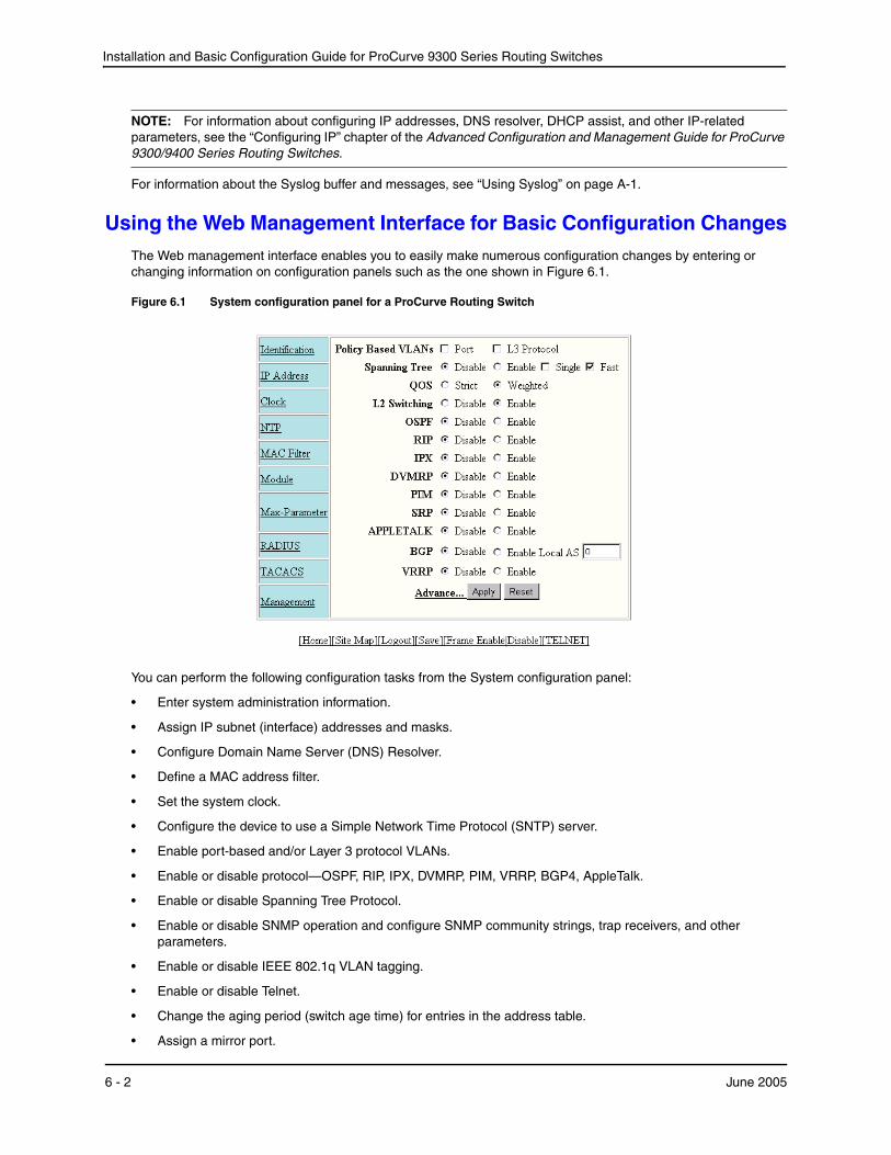
Installation and Basic Configuration Guide for ProCurve 9300 Series Routing Switches
NOTE: For information about configuring IP addresses, DNS resolver, DHCP assist, and other IP-related parameters, see the “Configuring IP” chapter of the Advanced Configuration and Management Guide for ProCurve 9300/9400 Series Routing Switches.
For information about the Syslog buffer and messages, see “Using Syslog” on page A-1.
Using the Web Management Interface for Basic Configuration ChangesThe Web management interface enables you to easily make numerous configuration changes by entering or changing information on configuration panels such as the one shown in Figure 6.1.
Figure 6.1 System configuration panel for a ProCurve Routing Switch
You can perform the following configuration tasks from the System configuration panel:
• Enter system administration information.
• Assign IP subnet (interface) addresses and masks.
• Configure Domain Name Server (DNS) Resolver.
• Define a MAC address filter.
• Set the system clock.
• Configure the device to use a Simple Network Time Protocol (SNTP) server.
• Enable port-based and/or Layer 3 protocol VLANs.
• Enable or disable protocol—OSPF, RIP, IPX, DVMRP, PIM, VRRP, BGP4, AppleTalk.
• Enable or disable Spanning Tree Protocol.
• Enable or disable SNMP operation and configure SNMP community strings, trap receivers, and other parameters.
• Enable or disable IEEE 802.1q VLAN tagging.
• Enable or disable Telnet.
• Change the aging period (switch age time) for entries in the address table.
• Assign a mirror port.
6 - 2 June 2005

Configuring Basic Features
• Modify system parameters.
• Add or delete modules.
• Modify tag type.
• Modify telnet timeout period.
• Modify broadcast limit.
• Enable or disable management using the Web management interface.
• Configure redundant management module parameters (Routing Switches with Management 2 or higher modules only).
The procedures in this chapter describe how to configure these parameters.
Configuring Basic System ParametersThe procedures in this section describe how to configure the following basic system parameters:
• System name, contact, and location – see “Entering System Administration Information” on page 6-3
• SNMP trap receiver, trap source address, and other parameters – see “Configuring Simple Network Management (SNMP) Parameters” on page 6-4
• Single source address for all Telnet packets – “Configuring an Interface as the Source for All Telnet Packets” on page 6-10
• Single source address for all TFTP packets – “Configuring an Interface as the Source for All TFTP Packets” on page 6-11
• System time using a Simple Network Time Protocol (SNTP) server or local system counter – see “Specifying a Simple Network Time Protocol (SNTP) Server” on page 6-11 and “Setting the System Clock” on page 6-13
• Default Gigabit negotiation mode – see “Changing the Default Gigabit Negotiation Mode” on page 6-15
• Broadcast, multicast, or unknown-unicast limits, if required to support slower third-party devices – see “Limiting Broadcast, Multicast, or Unknown-Unicast Rates” on page 6-17
• Banners that are displayed on users’ terminals when they enter the Privileged EXEC CLI level or access the device through Telnet – see “Configuring CLI Banners” on page 6-18.
• Terminal display length – see “Configuring Terminal Display” on page 6-19.
NOTE: For information about the Syslog buffer and messages, see “Using Syslog” on page A-1.
Entering System Administration InformationYou can configure a system name, contact, and location for a ProCurve Routing Switch and save the information locally in the configuration file for future reference. This information is not required for system operation but is suggested. When you configure a system name, the name replaces the default system name in the CLI command prompt. For example, if the system is an 9308M, the system name you configure replaces “ProCurveRS” in the command prompt.
The name, contact, and location each can be up to 32 alphanumeric characters.
USING THE CLI
Here is an example of how to configure a Routing Switch name, system contact, and location:
ProCurveRS(config)# hostname home home(config)# snmp-server contact Suzy Sanchez home(config)# snmp-server location Centerville home(config)# end home# write memory
June 2005 6 - 3
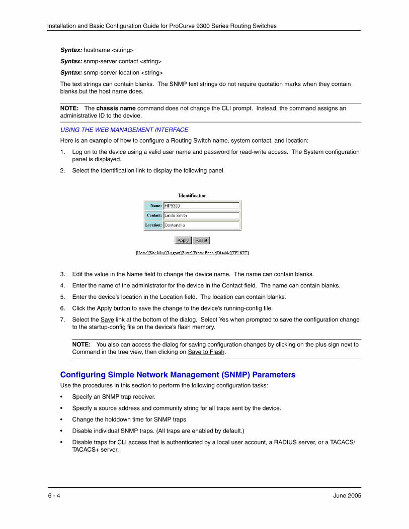
Installation and Basic Configuration Guide for ProCurve 9300 Series Routing Switches
Syntax: hostname <string>
Syntax: snmp-server contact <string>
Syntax: snmp-server location <string>
The text strings can contain blanks. The SNMP text strings do not require quotation marks when they contain blanks but the host name does.
NOTE: The chassis name command does not change the CLI prompt. Instead, the command assigns an administrative ID to the device.
USING THE WEB MANAGEMENT INTERFACE
Here is an example of how to configure a Routing Switch name, system contact, and location:
1. Log on to the device using a valid user name and password for read-write access. The System configuration panel is displayed.
2. Select the Identification link to display the following panel.
3. Edit the value in the Name field to change the device name. The name can contain blanks.
4. Enter the name of the administrator for the device in the Contact field. The name can contain blanks.
5. Enter the device’s location in the Location field. The location can contain blanks.
6. Click the Apply button to save the change to the device’s running-config file.
7. Select the Save link at the bottom of the dialog. Select Yes when prompted to save the configuration change to the startup-config file on the device’s flash memory.
NOTE: You also can access the dialog for saving configuration changes by clicking on the plus sign next to Command in the tree view, then clicking on Save to Flash.
Configuring Simple Network Management (SNMP) ParametersUse the procedures in this section to perform the following configuration tasks:
• Specify an SNMP trap receiver.
• Specify a source address and community string for all traps sent by the device.
• Change the holddown time for SNMP traps
• Disable individual SNMP traps. (All traps are enabled by default.)
• Disable traps for CLI access that is authenticated by a local user account, a RADIUS server, or a TACACS/TACACS+ server.
6 - 4 June 2005
Configuring Basic Features
NOTE: To add and modify “get” (read-only) and “set” (read-write) community strings, see the Security Guide for ProCurve 9300/9400 Series Routing Switches.
Specifying an SNMP Trap Receiver
You can specify a trap receiver to ensure that all SNMP traps sent by the HP device go to the same SNMP trap receiver or set of receivers, typically one or more host devices on the network. When you specify the host, you also specify a community string. The HP device sends all the SNMP traps to the specified host(s) and includes the specified community string. Administrators can therefore filter for traps from an HP device based on IP address or community string.
When you add a trap receiver, the software automatically encrypts the community string you associate with the receiver when the string is displayed by the CLI or Web management interface. If you want the software to show the community string in the clear, you must explicitly specify this when you add a trap receiver. In either case, the software does not encrypt the string in the SNMP traps sent to the receiver.
To specify the host to which the device sends all SNMP traps, use one of the following methods.
USING THE CLI
To add a trap receiver and encrypt the display of the community string, enter commands such as the following:
To specify an SNMP trap receiver and change the UDP port that will be used to receive traps, enter a command such as the following:
ProCurveRS(config)# # snmp-server host 2.2.2.2 0 mypublic port 200 ProCurveRS(config)# write memory
Syntax: snmp-server host <ip-addr> [0 | 1] <string> [port <value>]
The <ip-addr> parameter specifies the IP address of the trap receiver.
The 0 | 1 parameter specifies whether you want the software to encrypt the string (1) or show the string in the clear (0). The default is 0.
The <string> parameter specifies an SNMP community string configured on the HP device. The string can be a read-only string or a read-write string. The string is not used to authenticate access to the trap host but is instead a useful method for filtering traps on the host. For example, if you configure each of your HP devices that use the trap host to send a different community string, you can easily distinguish among the traps from different HP devices based on the community strings.
The command in the example above adds trap receiver 2.2.2.2 and configures the software to encrypt display of the community string. When you save the new community string to the startup-config file (using the write memory command), the software adds the following command to the file:
snmp-server host 2.2.2.2 1 <encrypted-string>
To add a trap receiver and configure the software to encrypt display of the community string in the CLI and Web management interface, enter commands such as the following:
ProCurveRS(config)# snmp-server host 2.2.2.2 0 HP9300-12 ProCurveRS(config)# write memory
The port <value> parameter allows you to specify which UDP port will be used by the trap receiver. This parameter allows you to configure several trap receivers in a system. With this parameter, a network management application can coexist in the same system. HP devices can be configured to send copies of traps to more than one network management application.
USING THE WEB MANAGEMENT INTERFACE
1. Log on to the device using a valid user name and password for read-write access.
2. Click the Management link to display the Management configuration panel.
June 2005 6 - 5
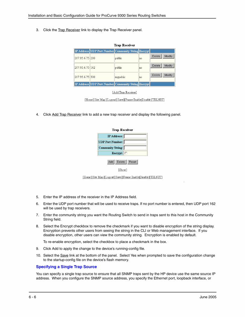
Installation and Basic Configuration Guide for ProCurve 9300 Series Routing Switches
3. Click the Trap Receiver link to display the Trap Receiver panel.
4. Click Add Trap Receiver link to add a new trap receiver and display the following panel.
5. Enter the IP address of the receiver in the IP Address field.
6. Enter the UDP port number that will be used to receive traps. If no port number is entered, then UDP port 162 will be used by trap receivers.
7. Enter the community string you want the Routing Switch to send in traps sent to this host in the Community String field.
8. Select the Encrypt checkbox to remove the checkmark if you want to disable encryption of the string display. Encryption prevents other users from seeing the string in the CLI or Web management interface. If you disable encryption, other users can view the community string. Encryption is enabled by default.
To re-enable encryption, select the checkbox to place a checkmark in the box.
9. Click Add to apply the change to the device’s running-config file.
10. Select the Save link at the bottom of the panel. Select Yes when prompted to save the configuration change to the startup-config file on the device’s flash memory.
Specifying a Single Trap Source
You can specify a single trap source to ensure that all SNMP traps sent by the HP device use the same source IP address. When you configure the SNMP source address, you specify the Ethernet port, loopback interface, or
6 - 6 June 2005
Configuring Basic Features
virtual routing interface that is the source for the traps. The HP device then uses the lowest-numbered IP address configured on the port or interface as the source IP address in the SNMP traps sent by the device.
Identifying a single source IP address for SNMP traps provides the following benefits:
• If your trap receiver is configured to accept traps only from specific links or IP addresses, you can use this feature to simplify configuration of the trap receiver by configuring the HP device to always send the traps from the same link or source address.
• If you specify a loopback interface as the single source for SNMP traps, SNMP trap receivers can receive traps regardless of the states of individual links. Thus, if a link to the trap receiver becomes unavailable but the receiver can be reached through another link, the receiver still receives the trap, and the trap still has the source IP address of the loopback interface.
To specify a port, loopback interface, or virtual routing interface whose lowest-numbered IP address the HP device must use as the source for all SNMP traps sent by the device, use the following CLI method.
USING THE CLI
To configure the device to send all SNMP traps from the first configured IP address on port 4/11, enter the following commands:
ProCurveRS(config)# snmp-server trap-source ethernet 4/11 ProCurveRS(config)# write memory
Syntax: snmp-server trap-source loopback <num> | ethernet <portnum> | ve <num>
The <num> parameter is a loopback interface or virtual routing interface number. If you specify an Ethernet port, the <portnum> is the port’s number.
To specify a loopback interface as the device’s SNMP trap source, enter commands such as the following:
ProCurveRS(config)# int loopback 1 ProCurveRS(config-lbif-1)# ip address 10.0.0.1/24 ProCurveRS(config-lbif-1)# exit ProCurveRS(config)# snmp-server trap-source loopback 1
The commands in this example configure loopback interface 1, assign IP address 10.00.1/24 to the loopback interface, then designate the interface as the SNMP trap source for this Routing Switch. Regardless of the port the HP device uses to send traps to the receiver, the traps always arrive from the same source IP address.
USING THE WEB MANAGEMENT INTERFACE
You cannot configure a trap source using the Web management interface.
Setting the SNMP Trap Holddown Time
When an HP device starts up, the software waits for Layer 2 convergence (STP) and Layer 3 convergence (OSPF) before beginning to send SNMP traps to external SNMP servers. Until convergence occurs, the device might not be able to reach the servers, in which case the messages are lost.
By default, an HP device uses a one-minute holddown time to wait for the convergence to occur before starting to send SNMP traps. After the holddown time expires, the device sends the traps, including traps such as “cold start” or “warm start” that occur before the holddown time expires.
You can change the holddown time to a value from one second to ten minutes.
USING THE CLI
To change the holddown time for SNMP traps, enter a command such as the following at the global CONFIG level of the CLI:
ProCurveRS(config)# snmp-server enable traps holddown-time 30
The command in this example changes the holddown time for SNMP traps to 30 seconds. The device waits 30 seconds to allow convergence in STP and OSPF before sending traps to the SNMP trap receiver.
Syntax: [no] snmp-server enable traps holddown-time <secs>
June 2005 6 - 7
Installation and Basic Configuration Guide for ProCurve 9300 Series Routing Switches
The <secs> parameter specifies the number of seconds and can be from 1 – 600 (ten minutes). The default is 60 seconds.
USING THE WEB MANAGEMENT INTERFACE
You cannot configure the parameter using the Web management interface.
Disabling SNMP Traps
ProCurve Routing Switches come with SNMP trap generation enabled by default for all traps. You can selectively disable one or more of the following traps.
NOTE: By default, all SNMP traps are enabled at system startup.
• SNMP authentication key
• Power supply failure
• Fan failure
• Cold start
• Link up
• Link down
• Bridge new root
• Bridge topology change
• Locked address violation
• Module insert
• Module remove
• BGP4
• OSPF
• VRRP
• VRRPE
USING THE CLI
To stop link down occurrences from being reported, enter the following:
ProCurveRS(config)# no snmp-server enable traps link-down
Syntax: [no] snmp-server enable traps <trap-type>
NOTE: For a list of the trap values, see the Command Line Interface Reference for ProCurve 9300/9400 Series Routing Switches.
USING THE WEB MANAGEMENT INTERFACE
To enable or disable individual SNMP traps:
1. Log on to the device using a valid user name and password for read-write access. The System configuration panel is displayed.
2. Select the Management link to display the Management panel.
3. Click on the Trap link to display the list of traps that you can enable or disable.
4. Select the Disable or Enable button next to the trap you want to disable or enable.
5. Click the Apply button to save the change to the device’s running-config file.
6. Select the Save link at the bottom of the dialog. Select Yes when prompted to save the configuration change to the startup-config file on the device’s flash memory.
6 - 8 June 2005
Configuring Basic Features
Disabling Syslog Messages and Traps for CLI Access
HP devices send Syslog messages and SNMP traps when a user logs into or out of the User EXEC or Privileged EXEC level of the CLI. The feature applies to users whose access is authenticated by an authentication-method list based on a local user account, RADIUS server, or TACACS/TACACS+ server.
NOTE: The Privileged EXEC level is sometimes called the “Enable” level, because the command for accessing this level is enable.
The feature is enabled by default.
Examples of Syslog Messages for CLI AccessWhen a user whose access is authenticated by a local user account, a RADIUS server, or a TACACS/TACACS+ server logs into or out of the CLI’s User EXEC or Privileged EXEC mode, the software generates a Syslog message and trap containing the following information:
• The time stamp
• The user name
• Whether the user logged in or out
• The CLI level the user logged into or out of (User EXEC or Privileged EXEC level)
NOTE: Messages for accessing the User EXEC level apply only to access through Telnet. The device does not authenticate initial access through serial connections but does authenticate serial access to the Privileged EXEC level. Messages for accessing the Privileged EXEC level apply to access through the serial connection or Telnet.
The following examples show login and logout messages for the User EXEC and Privileged EXEC levels of the CLI:
ProCurveRS(config)# show logging
Syslog logging: enabled (0 messages dropped, 0 flushes, 0 overruns) Buffer logging: level ACDMEINW, 12 messages logged level code: A=alert C=critical D=debugging M=emergency E=error I=informational N=notification W=warning
Static Log Buffer: Dec 15 19:04:14:A:Fan 1, fan on right connector, failed Dynamic Log Buffer (50 entries): Oct 15 18:01:11:info:dg logout from USER EXEC mode Oct 15 17:59:22:info:dg logout from PRIVILEGE EXEC mode Oct 15 17:38:07:info:dg login to PRIVILEGE EXEC mode Oct 15 17:38:03:info:dg login to USER EXEC mode
Syntax: show logging
The first message (the one on the bottom) indicates that user “dg” logged in to the CLI’s User EXEC level on October 15 at 5:38 PM and 3 seconds (Oct 15 17:38:03). The same user logged into the Privileged EXEC level four seconds later.
The user remained in the Privileged EXEC mode until 5:59 PM and 22 seconds. (The user could have used the CONFIG modes as well. Once you access the Privileged EXEC level, no further authentication is required to access the CONFIG levels.) At 6:01 PM and 11 seconds, the user ended the CLI session.
Disabling the Syslog Messages and TrapsLogging of CLI access is enabled by default. If you want to disable the logging, use the following method.
June 2005 6 - 9
Installation and Basic Configuration Guide for ProCurve 9300 Series Routing Switches
USING THE CLI
To disable logging of CLI access, enter the following commands:
ProCurveRS(config)# no logging enable user-login ProCurveRS(config)# write memory ProCurveRS(config)# end ProCurveRS# reload
Syntax: [no] logging enable user-login
USING THE WEB MANAGEMENT INTERFACE
You cannot disable logging of CLI access using the Web management interface.
Configuring an Interface as the Source for All Telnet PacketsYou can designate the lowest-numbered IP address configured an interface as the source IP address for all Telnet packets from the Routing Switch. Identifying a single source IP address for Telnet packets provides the following benefits:
• If your Telnet server is configured to accept packets only from specific links or IP addresses, you can use this feature to simplify configuration of the Telnet server by configuring the HP device to always send the Telnet packets from the same link or source address.
• If you specify a loopback interface as the single source for Telnet packets, Telnet servers can receive the packets regardless of the states of individual links. Thus, if a link to the Telnet server becomes unavailable but the client or server can be reached through another link, the client or server still receives the packets, and the packets still have the source IP address of the loopback interface.
The software contains separate CLI commands for specifying the source interface for Telnet, TACACS/TACACS+, and RADIUS packets. You can configure a source interface for one or more of these types of packets.
To specify an interface as the source for all Telnet packets from the device, use the following CLI method. The software uses the lowest-numbered IP address configured on the interface as the source IP address for Telnet packets originated by the device.
USING THE CLI
To specify the lowest-numbered IP address configured on a virtual routing interface as the device’s source for all Telnet packets, enter commands such as the following:
ProCurveRS(config)# int loopback 2 ProCurveRS(config-lbif-2)# ip address 10.0.0.2/24 ProCurveRS(config-lbif-2)# exit ProCurveRS(config)# ip telnet source-interface loopback 2
The commands in this example configure loopback interface 2, assign IP address 10.0.0.2/24 to the interface, then designate the interface as the source for all Telnet packets from the Routing Switch.
Syntax: ip telnet source-interface ethernet <portnum> | loopback <num> | ve <num>
The following commands configure an IP interface on an Ethernet port and designate the address port as the source for all Telnet packets from the Routing Switch.
ProCurveRS(config)# interface ethernet 1/4 ProCurveRS(config-if-1/4)# ip address 209.157.22.110/24 ProCurveRS(config-if-1/4)# exit ProCurveRS(config)# ip telnet source-interface ethernet 1/4
USING THE WEB MANAGEMENT INTERFACE
You cannot configure a single Telnet source using the Web management interface.
6 - 10 June 2005
Configuring Basic Features
Cancelling an Outbound Telnet SessionIf you want to cancel a Telnet session from the console to a remote Telnet server (for example, if the connection is frozen), you can terminate the Telnet session by doing the following:
1. At the console, press Ctrl-^ (Ctrl-Shift-6).
2. Press the X key to terminate the Telnet session.
Pressing Ctrl-^ twice in a row causes a single Ctrl-^ character to be sent to the Telnet server. After you press Ctrl-^, pressing any key other than X or Ctrl-^ returns you to the Telnet session.
Configuring an Interface as the Source for All TFTP PacketsYou can configure the device to use the lowest-numbered IP address configured on a loopback interface, virtual routing interface, or Ethernet port as the source for all TFTP packets from the device. The software uses the lowest-numbered IP address configured on the interface as the source IP address for the packets.
For example, to specify the lowest-numbered IP address configured on a virtual routing interface as the device’s source for all TFTP packets, enter commands such as the following:
ProCurveRS(config)# int ve 1 ProCurveRS(config-vif-1)# ip address 10.0.0.3/24 ProCurveRS(config-vif-1)# exit
ProCurveRS(config)# ip tftp source-interface ve 1
The commands in this example configure virtual routing interface 1, assign IP address 10.0.0.3/24 to the interface, then designate the interface's address as the source address for all TFTP packets
Syntax: [no] ip tftp source-interface ethernet <portnum> | loopback <num> | ve <num>
The default is the lowest-numbered IP address configured on the port through which the packet is sent. The address therefore changes, by default, depending on the port.
Specifying a Simple Network Time Protocol (SNTP) ServerYou can configure Routing Switches to consult SNTP servers for the current system time and date.
NOTE: ProCurve Routing Switches do not retain time and date information across power cycles. Unless you want to reconfigure the system time counter each time the system is reset, Hewlett-Packard recommends that you use the SNTP feature.
USING THE CLI
To identify an SNTP server with IP address 208.99.8.95 to act as the clock reference for a Routing Switch, enter the following:
ProCurveRS(config)# sntp server 208.99.8.95
Syntax: sntp server <ip-addr> | <hostname> [<version>]
The <version> parameter specifies the SNTP version the server is running and can be from 1 – 4. The default is 1. You can configure up to three SNTP servers by entering three separate sntp server commands.
By default, the Routing Switch polls its SNTP server every 30 minutes (1800 seconds). To configure the Routing Switch to poll for clock updates from a SNTP server every 15 minutes, enter the following:
ProCurveRS(config)# sntp poll-interval 900
Syntax: [no] sntp poll-interval <1-65535>
June 2005 6 - 11
Installation and Basic Configuration Guide for ProCurve 9300 Series Routing Switches
To display information about SNTP associations, enter the following command:
ProCurveRS# show sntp associations address ref clock st when poll delay disp ~207.95.6.102 0.0.0.0 16 202 4 0.0 5.45 ~207.95.6.101 0.0.0.0 16 202 0 0.0 0.0 * synced, ~ configured
Syntax: show sntp associations
The following table describes the information displayed by the show sntp associations command.
Table 6.1: Output from the show sntp associations command
This Field... Displays...
(leading character) One or both of the following:
* Synchronized to this peer
~ Peer is statically configured
address IP address of the peer
ref clock IP address of the peer’s reference clock
st NTP stratum level of the peer
when Amount of time since the last NTP packet was received from the peer
poll Poll interval in seconds
delay Round trip delay in milliseconds
disp Dispersion in seconds
To display information about SNTP status, enter the following command:
ProCurveRS# show sntp status Clock is unsynchronized, stratum = 0, no reference clock precision is 2**0 reference time is 0 .0 clock offset is 0.0 msec, root delay is 0.0 msec root dispersion is 0.0 msec, peer dispersion is 0.0 msec
Syntax: show sntp status
The following table describes the information displayed by the show sntp status command.
Table 6.2: Output from the show sntp status command
This Field... Indicates...
unsynchronized System is not synchronized to an NTP peer.
synchronized System is synchronized to an NTP peer.
stratum NTP stratum level of this system
6 - 12 June 2005
Configuring Basic Features
USING THE WEB MANAGEMENT INTERFACE
To identify a reference SNTP server for the system:
1. Log on to the device using a valid user name and password for read-write access. The System configuration panel is displayed.
2. Select the NTP link to display the NTP panel.
3. Optionally change the polling time by editing the value in the Polling Time field, then click Apply to save the change in the device’s running-config file. You can specify a number from 1 – 65535.
4. Select the NTP Server link to display the NTP Server panel.
NOTE: If you have already configured an SNTP server, the server information is listed; otherwise, select the Add NTP Server link at the bottom of the panel to add a new SNTP server.
5. Enter the IP address of the SNTP server.
6. Select the SNTP version the server is running from the version field’s pulldown menu. The default version is 1.
7. Click the Add button to save the change to the device’s running-config file.
8. Repeat steps 5 – 7 up to two more times to add a total of three SNTP servers.
9. Select the Save link at the bottom of the dialog. Select Yes when prompted to save the configuration change to the startup-config file on the device’s flash memory.
Setting the System ClockIn addition to SNTP support, ProCurve Routing Switches also allow you to set the system time counter. The time counter setting is not retained across power cycles and is not automatically synchronized with an SNTP server. The counter merely starts the system time and date clock with the time and date you specify.
NOTE: You can synchronize the time counter with your SNTP server time by entering the sntp sync command from the Privileged EXEC level of the CLI.
NOTE: Unless you identify an SNTP server for the system time and date, you will need to re-enter the time and date following each reboot.
For more details about SNTP, see “Specifying a Simple Network Time Protocol (SNTP) Server” on page 6-11.
reference clock IP Address of the peer (if any) to which the unit is synchronized
precision Precision of this system's clock (in Hz)
reference time Reference time stamp
clock offset Offset of clock to synchronized peer
root delay Total delay along the path to the root clock
root dispersion Dispersion of the root path
peer dispersion Dispersion of the synchronized peer
Table 6.2: Output from the show sntp status command (Continued)
This Field... Indicates...
June 2005 6 - 13

Installation and Basic Configuration Guide for ProCurve 9300 Series Routing Switches
USING THE CLI
To set the system time and date to 10:15:05 on October 15, 1999, enter the following command:
ProCurveRS# clock set 10:15:05 10-15-99
Syntax: [no] clock set <hh:mm:ss> <mm-dd-yy> | <mm-dd-yyyy>
By default, ProCurve Routing Switches do not change the system time for daylight savings time. To enable daylight savings time, enter the following command:
ProCurveRS# clock summer-time
Syntax: clock summer-time
Although SNTP servers typically deliver the time and date in Greenwich Mean Time (GMT), you can configure the Routing Switch to adjust the time for any one-hour offset from GMT or for one of the following U.S. time zones:
• US Pacific (default)
• Alaska
• Aleutian
• Arizona
• Central
• East-Indiana
• Eastern
• Hawaii
• Michigan
• Mountain
• Pacific
• Samoa
The default is US Pacific.
To change the time zone to Australian East Coast time (which is normally 10 hours ahead of GMT), enter the following command:
ProCurveRS(config)# clock timezone gmt gmt+10
Syntax: clock timezone gmt gmt | us <time-zone>
You can enter one of the following values for <time-zone>:
• US time zones (us): alaska, aleutian, arizona, central, east-indiana, eastern, hawaii, michigan, mountain, pacific, samoa.
• GMT time zones (gmt): gmt+12, gmt+11, gmt+10...gmt+01, gmt+00, gmt-01...gmt-10, gmt-11, gmt-12.
USING THE WEB MANAGEMENT INTERFACE
To set the local time for the system:
1. Log on to the device using a valid user name and password for read-write access. The System configuration panel is displayed.
6 - 14 June 2005
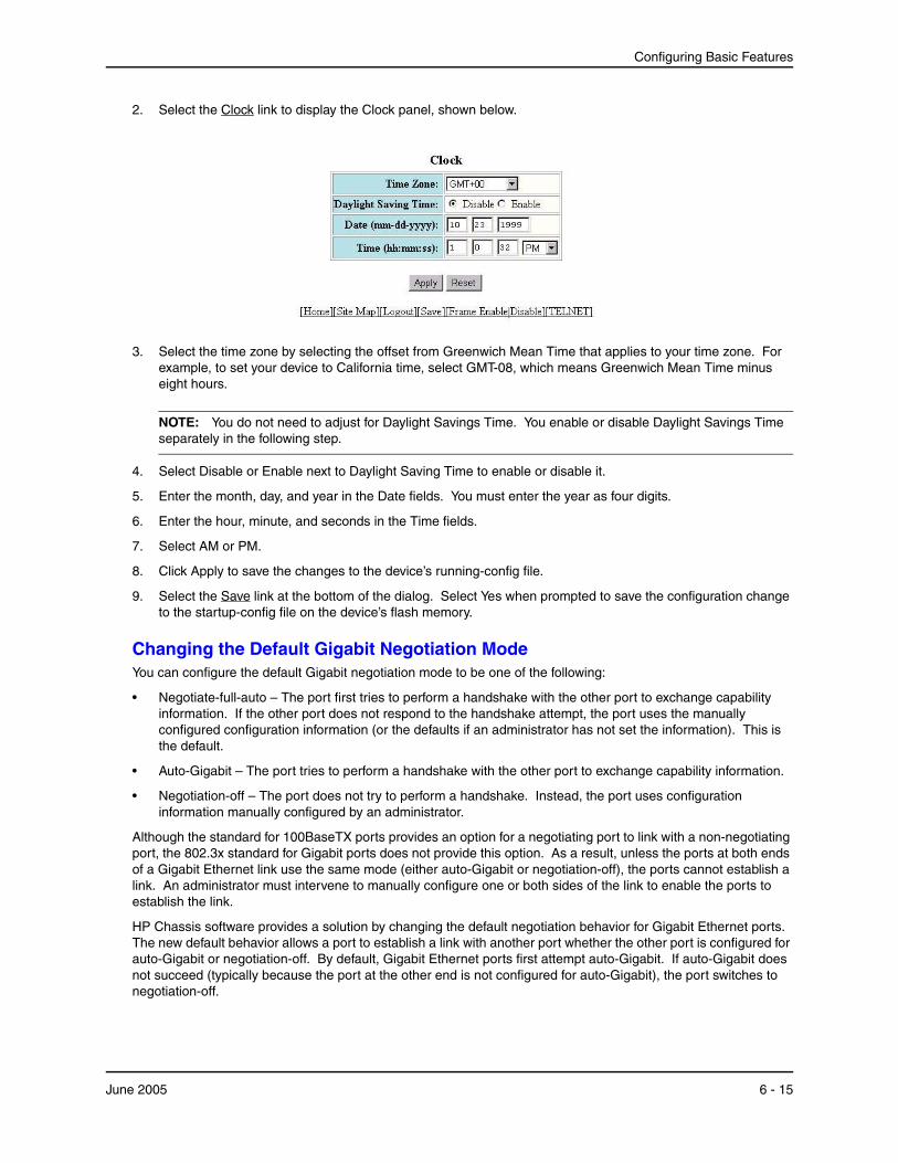
Configuring Basic Features
2. Select the Clock link to display the Clock panel, shown below.
3. Select the time zone by selecting the offset from Greenwich Mean Time that applies to your time zone. For example, to set your device to California time, select GMT-08, which means Greenwich Mean Time minus eight hours.
NOTE: You do not need to adjust for Daylight Savings Time. You enable or disable Daylight Savings Time separately in the following step.
4. Select Disable or Enable next to Daylight Saving Time to enable or disable it.
5. Enter the month, day, and year in the Date fields. You must enter the year as four digits.
6. Enter the hour, minute, and seconds in the Time fields.
7. Select AM or PM.
8. Click Apply to save the changes to the device’s running-config file.
9. Select the Save link at the bottom of the dialog. Select Yes when prompted to save the configuration change to the startup-config file on the device’s flash memory.
Changing the Default Gigabit Negotiation ModeYou can configure the default Gigabit negotiation mode to be one of the following:
• Negotiate-full-auto – The port first tries to perform a handshake with the other port to exchange capability information. If the other port does not respond to the handshake attempt, the port uses the manually configured configuration information (or the defaults if an administrator has not set the information). This is the default.
• Auto-Gigabit – The port tries to perform a handshake with the other port to exchange capability information.
• Negotiation-off – The port does not try to perform a handshake. Instead, the port uses configuration information manually configured by an administrator.
Although the standard for 100BaseTX ports provides an option for a negotiating port to link with a non-negotiating port, the 802.3x standard for Gigabit ports does not provide this option. As a result, unless the ports at both ends of a Gigabit Ethernet link use the same mode (either auto-Gigabit or negotiation-off), the ports cannot establish a link. An administrator must intervene to manually configure one or both sides of the link to enable the ports to establish the link.
HP Chassis software provides a solution by changing the default negotiation behavior for Gigabit Ethernet ports. The new default behavior allows a port to establish a link with another port whether the other port is configured for auto-Gigabit or negotiation-off. By default, Gigabit Ethernet ports first attempt auto-Gigabit. If auto-Gigabit does not succeed (typically because the port at the other end is not configured for auto-Gigabit), the port switches to negotiation-off.
June 2005 6 - 15
Installation and Basic Configuration Guide for ProCurve 9300 Series Routing Switches
Backward Compatibility
When you upgrade a Routing Switch that is running software older than 05.2.00, the new software makes modifications to the running-config and startup-config files to ensure that the negotiation settings remain unchanged for the installed device. For new devices running 05.2.00, the default for all Gigabit Ethernet ports is negotiate-full-auto.
To provide the backward compatibility, the software places a line in the running-config file to identify the software version that generated the file. For software release 05.2.00, the version line is as follows: “version 05.2.00”. When you save configuration changes to the startup-config file, the software assumes, based on the presence of the version line in the running-config file, that the device is running software release 05.2.00 or later, which contains the change to the Gigabit Ethernet negotiation default.
If the device already has a startup-config file when you update to software release 05.2.00, the software adds the following command to the startup-config file: gig-default neg-off. This command sets the global negotiation mode to negotiation-off, the default behavior in software releases earlier than 05.2.00. By setting the default mode to negotiation-off, the new software ensures that the device’s Gigabit Ethernet links continue to operate as before. (Although you cannot set a global default for Gigabit Ethernet negotiation in software releases earlier than 05.2.00, the implicit default behavior is negotiation-off.)
If the startup-config file contains the auto-gig command to configure individual ports for auto-Gigabit, the command is changed to the new format, gig-default auto-gig. Thus, the ports continue to use the auto-Gigabit setting.
Changing the Negotiation Mode
You can change the negotiation mode globally and for individual ports. Use either of the following methods.
USING THE CLI
To change the mode globally, enter a command such as the following:
ProCurveRS(config)# gig-default neg-off
This command changes the global setting to negotiation-off. The global setting applies to all Gigabit Ethernet ports except those for which you set a different negotiation mode on the port level.
To change the mode for individual ports, enter commands such as the following:
ProCurveRS(config)# int ethernet 4/1 to 4/4 ProCurveRS(config-mif-4/1-4/4)# gig-default auto-gig
This command overrides the global setting and sets the negotiation mode to auto-Gigabit for ports 4/1 – 4/4.
Here is the syntax for globally changing the negotiation mode.
Syntax: gig-default neg-full-auto | auto-gig | neg-off
Here is the syntax for changing the negotiation mode on individual ports.
Syntax: gig-default neg-full-auto | auto-gig | neg-off
USING THE WEB MANAGEMENT INTERFACE
To change the global default:
1. Log on to the device using a valid user name and password for read-write access. The System configuration panel is displayed.
2. Select the Advance link to display the advanced System parameters panel.
3. Select one of the following values from the Gig Port Default field’s pulldown menu:
• Neg-off – The port does not try to perform a handshake. Instead, the port uses configuration information manually configured by an administrator.
• Auto-Gig – The port tries to perform a handshake with the other port to exchange capability information.
• Neg-Full-Auto – The port first tries to perform a handshake with the other port to exchange capability information. If the other port does not respond to the handshake attempt, the port uses the manually
6 - 16 June 2005
Configuring Basic Features
configured configuration information (or the defaults if an administrator has not set the information).
4. Click Apply to save the changes to the device’s running-config file.
5. Select the Save link at the bottom of the dialog. Select Yes when prompted to save the configuration change to the startup-config file on the device’s flash memory.
To override the global negotiation mode for an individual port:
1. Log on to the device using a valid user name and password for read-write access. The System configuration panel is displayed.
2. Click on the plus sign next to Configure in the tree view to display the configuration options.
3. Click on the plus sign next to Port in the tree view to display the configuration options.
4. Select the link for the port type you want to change (for example, Ethernet) to display the Port table.
5. Click on the Modify button next to the row of information for the port you want to reconfigure.
6. Select one of the following values from the Gig Port Default field’s pulldown menu:
• Default – The port uses the negotiation mode that was set at the global level.
• Neg-off – The port does not try to perform a handshake. Instead, the port uses configuration information manually configured by an administrator.
• Auto-Gig – The port tries to perform a handshake with the other port to exchange capability information.
• Neg-Full-Auto – The port first tries to perform a handshake with the other port to exchange capability information. If the other port does not respond to the handshake attempt, the port uses the manually configured configuration information (or the defaults if an administrator has not set the information).
7. Click Apply to save the changes to the device’s running-config file.
8. Select the Save link at the bottom of the dialog. Select Yes when prompted to save the configuration change to the startup-config file on the device’s flash memory.
Limiting Broadcast, Multicast, or Unknown-Unicast RatesHP devices can forward all traffic at wire speed. However, some third-party networking devices cannot handle high forwarding rates for broadcast, multicast, or unknown-unicast packets. You can limit the number of broadcast, multicast, or unknown-unicast packets an HP device forwards each second using the following methods.
The limits are individually configurable for broadcasts, multicasts, and unknown-unicasts. You can configure limits globally and on individual ports. The valid range is 1 – 4294967295 packets per second. If you specify 0, limiting is disabled. Limiting is disabled by default.
NOTE: By default, IP Multicast (including IGMP) is disabled. You can enable it using the ip multicast passive | active command. As long as IP Multicast is enabled (regardless of whether it is passive or active), no IP Multicast packets (not even IGMP packets) are limited.
Limiting Broadcasts
To limit the number of broadcast packets an HP device can forward each second, use the following CLI method.
USING THE CLI
To globally limit the number of broadcast packets an 9300 series Routing Switch forwards to 100,000 per second, enter the following command at the global CONFIG level of the CLI:
ProCurveRS(config)# broadcast limit 100000 ProCurveRS(config)# write memory
To limit the number of broadcast packets sent on port 1/3 to 80,000, enter the following commands:
ProCurveRS(config)# int ethernet 1/3 ProCurveRS(config-if-1/3)# broadcast limit 80000
June 2005 6 - 17

Installation and Basic Configuration Guide for ProCurve 9300 Series Routing Switches
ProCurveRS(config-if-1/3)# write memory
USING THE WEB MANAGEMENT INTERFACE
You cannot perform this procedure using the Web management interface.
Limiting Multicasts
To limit the number of multicast packets an HP device can forward each second, use the following CLI method.
USING THE CLI
To globally limit the number of multicast packets an 9300 series Routing Switch forwards to 120,000 per second, enter the following command at the global CONFIG level of the CLI:
ProCurveRS(config)# multicast limit 120000 ProCurveRS(config)# write memory
To limit the number of multicast packets sent on port 3/6 to 55,000, enter the following commands:
ProCurveRS(config)# int ethernet 3/6 ProCurveRS(config-if-3/6)# multicast limit 55000 ProCurveRS(config-if-3/6)# write memory
USING THE WEB MANAGEMENT INTERFACE
You cannot perform this procedure using the Web management interface.
Limiting Unknown Unicasts
To limit the number unknown unicast packets an HP device can forward each second, use the following CLI method.
USING THE CLI
To globally limit the number of unknown unicast packets an 9300 series Routing Switch forwards to 110,000 per second, enter the following command at the global CONFIG level of the CLI:
ProCurveRS(config)# unknown-unicast limit 110000 ProCurveRS(config)# write memory
To limit the number of unknown unicast packets sent on port 4/2 to 40,000, enter the following commands:
ProCurveRS(config)# int ethernet 4/2 ProCurveRS(config-if-4/2)# unknown-unicast limit 40000 ProCurveRS(config-if-4/2)# write memory
USING THE WEB MANAGEMENT INTERFACE
You cannot perform this procedure using the Web management interface.
Configuring CLI BannersHP devices can be configured to display a greeting message on users’ terminals when they enter the Privileged EXEC CLI level or access the device through Telnet. In addition, an HP device can display a message on the Console when an incoming Telnet CLI session is detected.
Setting a Message of the Day Banner
You can configure the HP device to display a message on a user’s terminal when he or she establishes a Telnet CLI session. For example, to display the message “Welcome to HP ProCurve!” when a Telnet CLI session is established:
ProCurveRS(config)# banner motd $ (Press Return) Enter TEXT message, End with the character '$'. Welcome to HP ProCurve!! $
A delimiting character is established on the first line of the banner motd command. You begin and end the message with this delimiting character. The delimiting character can be any character except “ (double-quotation mark) and cannot appear in the banner text. In this example, the delimiting character is $ (dollar sign). The text in
6 - 18 June 2005
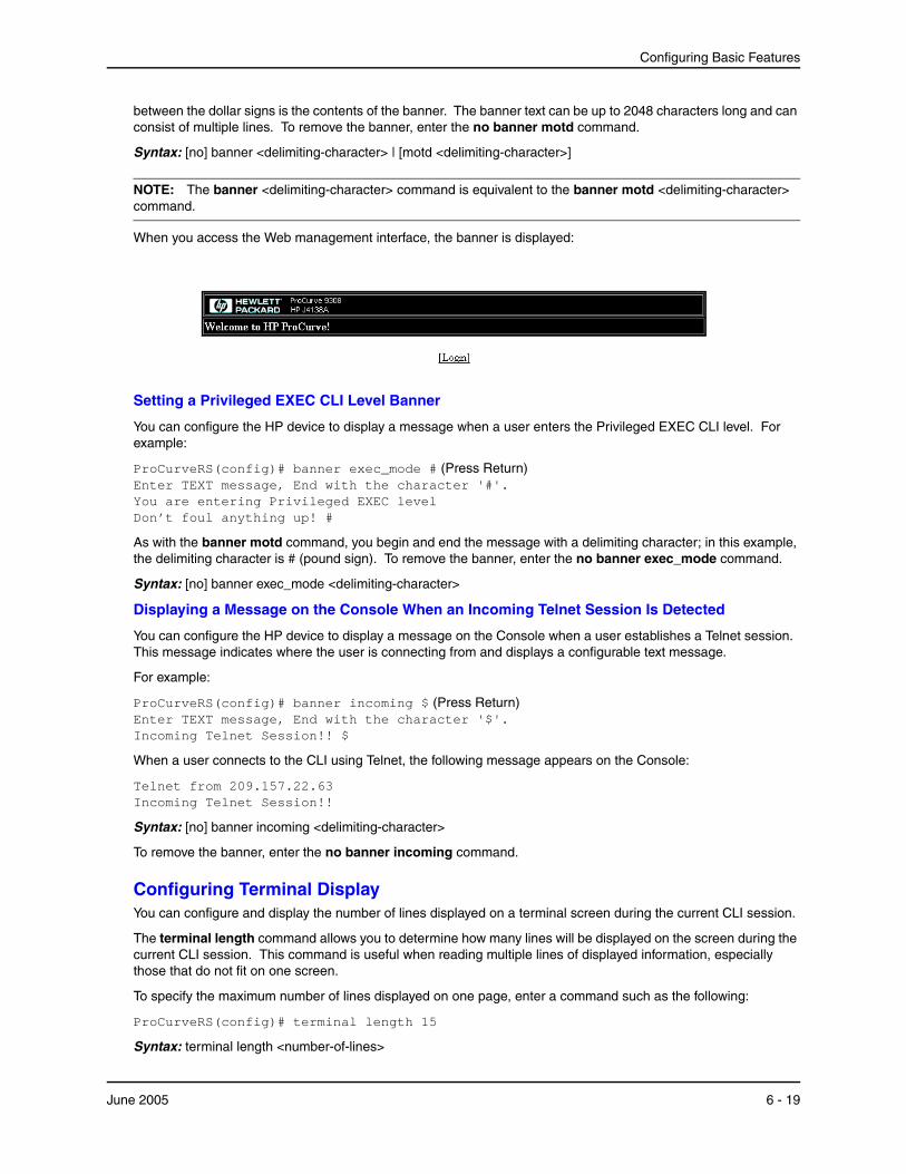
Configuring Basic Features
between the dollar signs is the contents of the banner. The banner text can be up to 2048 characters long and can consist of multiple lines. To remove the banner, enter the no banner motd command.
Syntax: [no] banner <delimiting-character> | [motd <delimiting-character>]
NOTE: The banner <delimiting-character> command is equivalent to the banner motd <delimiting-character> command.
When you access the Web management interface, the banner is displayed:
Setting a Privileged EXEC CLI Level Banner
You can configure the HP device to display a message when a user enters the Privileged EXEC CLI level. For example:
ProCurveRS(config)# banner exec_mode # (Press Return) Enter TEXT message, End with the character '#'. You are entering Privileged EXEC level Don’t foul anything up! #
As with the banner motd command, you begin and end the message with a delimiting character; in this example, the delimiting character is # (pound sign). To remove the banner, enter the no banner exec_mode command.
Syntax: [no] banner exec_mode <delimiting-character>
Displaying a Message on the Console When an Incoming Telnet Session Is Detected
You can configure the HP device to display a message on the Console when a user establishes a Telnet session. This message indicates where the user is connecting from and displays a configurable text message.
For example:
ProCurveRS(config)# banner incoming $ (Press Return) Enter TEXT message, End with the character '$'. Incoming Telnet Session!! $
When a user connects to the CLI using Telnet, the following message appears on the Console:
Telnet from 209.157.22.63 Incoming Telnet Session!!
Syntax: [no] banner incoming <delimiting-character>
To remove the banner, enter the no banner incoming command.
Configuring Terminal DisplayYou can configure and display the number of lines displayed on a terminal screen during the current CLI session.
The terminal length command allows you to determine how many lines will be displayed on the screen during the current CLI session. This command is useful when reading multiple lines of displayed information, especially those that do not fit on one screen.
To specify the maximum number of lines displayed on one page, enter a command such as the following:
ProCurveRS(config)# terminal length 15
Syntax: terminal length <number-of-lines>
June 2005 6 - 19
Installation and Basic Configuration Guide for ProCurve 9300 Series Routing Switches
The <number-of-lines> parameter indicates the maximum number of lines that will be displayed on a full screen of text during the current session. If the displayed information requires more than one page, the terminal pauses. Pressing the space bar displays the next page.
The default for <number-of-lines> is 24. Entering a value of 0 prevents the terminal from pausing between multiple output pages:
Checking the Length of Terminal DisplaysThe show terminal command specifies the number of lines that will be displayed on the screen as specified by the terminal length, page display, and skip-page-display commands. It also shows if the enable skip-page-display command has been configured. The enable skip-page-display command allows you to use the skip-page-display to disable the configured page-display settings.
ProCurveRS(config)# show terminal Length: 24 lines Page display mode (session): enabled Page display mode (global): enabled
Configuring Basic Port ParametersThe procedures in this section describe how to configure the following port parameters:
• Name – see “Assigning a Port Name” on page 6-22
• Speed – see “Modifying Port Speed” on page 6-23
• Mode (half-duplex or full-duplex) – see “Modifying Port Mode” on page 6-24
• Status – see “Disabling or Re-Enabling a Port” on page 6-24
• Flow control – see “Disabling or Re-Enabling Flow Control” on page 6-25
• Gigabit negotiate mode – see “Changing the 802.3x Gigabit Negotiation Mode” on page 6-26
• QoS priority – see “Modifying Port Priority (QoS)” on page 6-27
NOTE: To modify Layer 2, Layer 3, or Layer 4 features on a port, see the appropriate section in this chapter or other chapters. For example, to modify Spanning Tree Protocol (STP) parameters for a port, see “Modifying STP Bridge and Port Parameters” on page 6-28.
NOTE: To configure trunk groups or dynamic link aggregation, see “Configuring Trunk Groups and Dynamic Link Aggregation” on page 7-1.
All HP ports are pre-configured with default values that allow the device to be fully operational at initial startup without any additional configuration. However, in some cases, changes to the port parameters may be necessary to adjust to attached devices or other network requirements.
The current port configuration for all ports is displayed when you select the Port link from the Configure tree. You can easily determine a port’s state by observing the color in the Port field.
• Red – indicates there is no link.
• Green – indicates the link is good.
6 - 20 June 2005
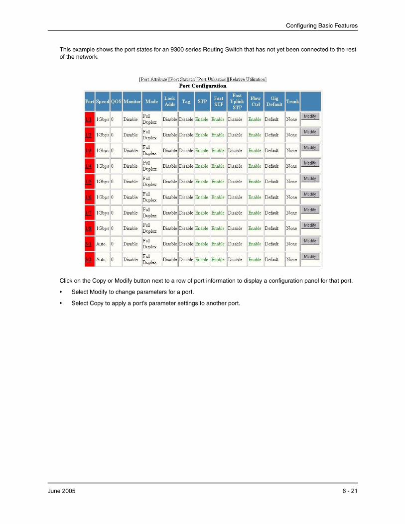
Configuring Basic Features
This example shows the port states for an 9300 series Routing Switch that has not yet been connected to the rest of the network.
Click on the Copy or Modify button next to a row of port information to display a configuration panel for that port.
• Select Modify to change parameters for a port.
• Select Copy to apply a port’s parameter settings to another port.
June 2005 6 - 21
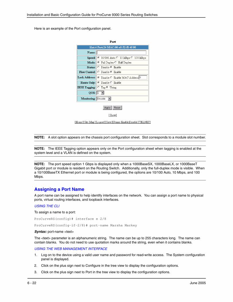
Installation and Basic Configuration Guide for ProCurve 9300 Series Routing Switches
Here is an example of the Port configuration panel.
NOTE: A slot option appears on the chassis port configuration sheet. Slot corresponds to a module slot number.
NOTE: The IEEE Tagging option appears only on the Port configuration sheet when tagging is enabled at the system level and a VLAN is defined on the system.
NOTE: The port speed option 1 Gbps is displayed only when a 1000BaseSX, 1000BaseLX, or 1000BaseT Gigabit port or module is resident on the Routing Switch. Additionally, only the full-duplex mode is visible. When a 10/100BaseTX Ethernet port or module is being configured, the options are 10/100 Auto, 10 Mbps, and 100 Mbps.
Assigning a Port NameA port name can be assigned to help identify interfaces on the network. You can assign a port name to physical ports, virtual routing interfaces, and loopback interfaces.
USING THE CLI
To assign a name to a port:
ProCurveRS(config)# interface e 2/8
ProCurveRS(config-if-2/8)# port-name Marsha Markey
Syntax: port-name <text>
The <text> parameter is an alphanumeric string. The name can be up to 255 characters long. The name can contain blanks. You do not need to use quotation marks around the string, even when it contains blanks.
USING THE WEB MANAGEMENT INTERFACE
1. Log on to the device using a valid user name and password for read-write access. The System configuration panel is displayed.
2. Click on the plus sign next to Configure in the tree view to display the configuration options.
3. Click on the plus sign next to Port in the tree view to display the configuration options.
6 - 22 June 2005
Configuring Basic Features
4. Select the link to the port type you want (for example, Ethernet) to display the Port table.
5. Click on the Modify button next to the row of information for the port you want to reconfigure.
6. Enter a name in the Name field.
7. Click Apply to save the changes to the device’s running-config file.
8. Select the Save link at the bottom of the dialog. Select Yes when prompted to save the configuration change to the startup-config file on the device’s flash memory.
Modifying Port SpeedEach of the 10BaseT/100BaseTX ports is designed to auto-sense and auto-negotiate the speed and mode of the connected device. If the attached device does not support this operation, you can manually enter the port speed to operate at either 10 Mbps or 100 Mbps. The default value for 10BaseT/100BaseTX ports is 10/100 Auto-sense.
The 100BaseFX ports operate in the full-duplex mode at 100 Mbps only and cannot be modified.
The 1000BaseSX, 1000BaseLX, and 1000BaseT ports operate in the full-duplex mode at one Gigabit only and cannot be modified.
NOTE: Modifying the port speed of a port that has a pre-configured rate limit policy may result in the inability to remove the port's rate limit policy.
USING THE CLI
To change the port speed of interface 1/8 from the default of 10/100 auto-sense to 10 Mbps operating at full-duplex, enter the following:
ProCurveRS(config)# interface e 1/8 ProCurveRS(config-if-1/8)# speed-duplex 10-full
Syntax: speed-duplex <value>
The <value> can be one of the following:
• 10-full
• 10-half
• 100-full
• 100-half
• auto
The default is auto.
USING THE WEB MANAGEMENT INTERFACE
To modify port speed:
1. Log on to the device using a valid user name and password for read-write access. The System configuration panel is displayed.
2. Click on the plus sign next to Configure in the tree view to display the configuration options.
3. Click on the plus sign next to Port in the tree view to display the configuration options.
4. Select the link to the port type you want (for example, Ethernet) to display the Port table.
5. Click on the Modify button next to the row of information for the port you want to reconfigure.
6. Click next to Full Duplex if you want to change the mode to full-duplex only. (This applies only to 10/100 ports.)
7. Click Disable or Enable next to Auto Negotiate to enable or disable auto-negotiation.
8. Click Apply to save the changes to the device’s running-config file.
June 2005 6 - 23
Installation and Basic Configuration Guide for ProCurve 9300 Series Routing Switches
9. Select the Save link at the bottom of the dialog. Select Yes when prompted to save the configuration change to the startup-config file on the device’s flash memory.
Modifying Port ModeYou can configure a port to accept either full-duplex (bi-directional) or half-duplex (uni-directional) traffic. This option is available only for 10/100 Mbps ports. The 100BaseFx, 1000BaseSx, and 1000BaseLx ports operate only at full-duplex.
USING THE CLI
Port duplex mode and port speed are modified by the same command.
To change the port speed of interface 1/8 from the default of 10/100 auto-sense to 10 Mbps operating at full-duplex, enter the following:
ProCurveRS(config)# interface e 1/8 ProCurveRS(config-if-1/8)# speed-duplex 10-full
Syntax: speed-duplex <value>
The <value> can be one of the following:
• 10-full
• 10-half
• 100-full
• 100-half
• auto
The default is auto.
USING THE WEB MANAGEMENT INTERFACE
To modify port mode:
1. Log on to the device using a valid user name and password for read-write access. The System configuration panel is displayed.
2. Click on the plus sign next to Configure in the tree view to display the configuration options.
3. Click on the plus sign next to Port in the tree view to display the configuration options.
4. Select the link to the port type you want (for example, Ethernet) to display the Port table.
5. Click on the Modify button next to the row of information for the port you want to reconfigure.
6. Click next to Full Duplex to select or de-select full duplex mode. Full-duplex mode is selected when the radio button (small circle) next to Full Duplex contains a black dot.
7. Click Apply to save the changes to the device’s running-config file.
8. Select the Save link at the bottom of the dialog. Select Yes when prompted to save the configuration change to the startup-config file on the device’s flash memory.
Disabling or Re-Enabling a PortThe port can be made inactive (disable) or active (enable) by selecting the appropriate status option. The default value for a port is enabled.
USING THE CLI
To disable port 8 on module 1 of a ProCurve Routing Switch, enter the following:
ProCurveRS(config)# interface e 1/8 ProCurveRS(config-if-1/8)# disable
Syntax: disable
6 - 24 June 2005
Configuring Basic Features
Syntax: enable
You also can disable or re-enable a virtual routing interface. To do so, enter commands such as the following:
ProCurveRS(config)# interface ve v1 ProCurveRS(config-vif-1)# disable
Syntax: disable
To re-enable a virtual routing interface, enter the enable command at the Interface configuration level. For example, to re-enable virtual routing interface v1, enter the following command:
ProCurveRS(config-vif-1)# enable
Syntax: enable
USING THE WEB MANAGEMENT INTERFACE
To disable or enable a port:
1. Log on to the device using a valid user name and password for read-write access. The System configuration panel is displayed.
2. Click on the plus sign next to Configure in the tree view to display the configuration options.
3. Click on the plus sign next to Port in the tree view to display the configuration options.
4. Select the link to the port type you want (for example, Ethernet) to display the Port table.
5. Click on the Modify button next to the row of information for the port you want to reconfigure.
6. Select either Enable or Disable option next to the Status option.
7. Click Apply to save the changes to the device’s running-config file.
8. Select the Save link at the bottom of the dialog. Select Yes when prompted to save the configuration change to the startup-config file on the device’s flash memory.
NOTE: You cannot disable or re-enable a virtual routing interface using the Web management interface.
Disabling or Re-Enabling Flow ControlYou can configure full-duplex ports on a system to operate with or without flow control (802.3x). Flow control is enabled by default.
USING THE CLI
To disable flow control on full-duplex ports on a system, enter the following:
ProCurveRS(config)# no flow-control
To turn the feature back on:
ProCurveRS(config)# flow-control
Syntax: [no] flow-control
USING THE WEB MANAGEMENT INTERFACE
To disable or enable flow control on full-duplex ports on a system:
1. Log on to the device using a valid user name and password for read-write access. The System configuration panel is displayed.
2. Click on the plus sign next to Configure in the tree view to display the configuration options.
3. Click on the plus sign next to Port in the tree view to display the configuration options.
4. Select the link to the port type you want (for example, Ethernet) to display the Port table.
5. Click on the Modify button next to the row of information for the port you want to reconfigure.
June 2005 6 - 25

Installation and Basic Configuration Guide for ProCurve 9300 Series Routing Switches
6. Select either Enable or Disable next to Flow Control.
7. Click Apply to save the changes to the device’s running-config file.
8. Select the Save link at the bottom of the dialog. Select Yes when prompted to save the configuration change to the startup-config file on the device’s flash memory.
Specifying Threshold Values for Flow Control
The 802.3x flow control specification provides a method for slowing traffic from a sender when a port is receiving more traffic than it can handle. Specifically, the receiving device can send out 802.3x PAUSE frames that request that the sender stop sending traffic for a period of time.
In software release 07.6.00 and higher, the HP device generates 802.3x PAUSE frames when the number of buffers available to a module's Buffer Manager (BM) drops below a threshold value. A module's BM can start running out of buffers when a port receives more traffic than it can handle. In addition, the device drops the lowest priority traffic when the number of available buffers drops below a second threshold. When the number of available buffers returns to a higher level, the device sends out another PAUSE frame that tells the sender to resume sending traffic normally. You can specify values for both thresholds, as well as the module where the thresholds are to take effect.
NOTE: To use this feature, 802.3x flow control must be enabled globally on the device. By default, 802.3x flow control is enabled on HP devices, but can be disabled with the no flow-control command.
To specify threshold values for flow control, enter the following command:
ProCurveRS(config)# qd-flow sink 75 sunk 50 slot 1
Syntax: qd-flow sink <sinking-threshold> sunk <sunk-threshold> slot <slot>
The threshold values are percentages of the total number of buffers available to a module's Buffer Manager.
When the <sinking-threshold> is reached, the HP device sends out 802.3x PAUSE frames telling the sender to stop sending traffic for a period of time.
When the <sunk-threshold> is reached, the HP device drops traffic at the specified priority level.
The <slot> parameter specifies the location of the module where the thresholds are to take effect.
Changing the 802.3x Gigabit Negotiation ModeThe globally configured Gigabit negotiation mode for 802.3x flow control is the default mode for all Gigabit ports. You can override the globally configured default and set individual ports to the following:
• Negotiate-full-auto – The port first tries to perform a handshake with the other port to exchange capability information. If the other port does not respond to the handshake attempt, the port uses the manually configured configuration information (or the defaults if an administrator has not set the information). This is the default.
• Auto-Gigabit – The port tries to perform a handshake with the other port to exchange capability information.
• Negotiation-off – The port does not try to perform a handshake. Instead, the port uses configuration information manually configured by an administrator.
USING THE CLI
To change the mode for individual ports, enter commands such as the following:
ProCurveRS(config)# int ethernet 4/1 to 4/4 ProCurveRS(config-mif-4/1-4/4)# gig-default auto-gig
This command overrides the global setting and sets the negotiation mode to auto-Gigabit for ports 4/1 – 4/4.
Syntax: gig-default neg-full-auto | auto-gig | neg-off
USING THE WEB MANAGEMENT INTERFACE
To override the global 802.3x negotiation mode for an Gigabit individual port:
6 - 26 June 2005
Configuring Basic Features
1. Log on to the device using a valid user name and password for read-write access. The System configuration panel is displayed.
2. Click on the plus sign next to Configure in the tree view to display the configuration options.
3. Click on the plus sign next to Port in the tree view to display the configuration options.
4. Select the link to the port type you want (for example, Ethernet) to display the Port table.
5. Click on the Modify button next to the row of information for the port you want to reconfigure.
6. Select one of the following values from the Gig Port Default field’s pulldown menu:
• Default – The port uses the negotiation mode that was set at the global level.
• Neg-off – The port does not try to perform a handshake. Instead, the port uses configuration information manually configured by an administrator.
• Auto-Gig – The port tries to perform a handshake with the other port to exchange capability information.
• Neg-Full-Auto – The port first tries to perform a handshake with the other port to exchange capability information. If the other port does not respond to the handshake attempt, the port uses the manually configured configuration information (or the defaults if an administrator has not set the information).
7. Click Apply to save the changes to the device’s running-config file.
8. Select the Save link at the bottom of the dialog. Select Yes when prompted to save the configuration change to the startup-config file on the device’s flash memory.
NOTE: You also can access the dialog for saving configuration changes by clicking on Command in the tree view, then clicking on Save to Flash.
Modifying Port Priority (QoS)You can give preference to the inbound traffic on specific ports by changing the Quality of Service (QoS) level on those ports. For information and procedures, see the “Configuring Quality of Service” chapter in the Advanced Configuration and Management Guide for ProCurve 9300/9400 Series Routing Switches.
Configuring Basic Layer 2 ParametersThe procedures in this section describe how to configure the following Layer 2 parameters.
• Spanning Tree Protocol (STP) – see “Enabling or Disabling the Spanning Tree Protocol (STP)” on page 6-27
NOTE: The procedures in this chapter describe how to configure basic STP parameters. For more information about STP, see “Configuring Spanning Tree Protocol (STP) and Advanced STP Features” on page 8-1.
• Aging time for learned MAC address entries – see “Changing the MAC Age Time” on page 6-30
• Static, non-aging MAC address entries – see “Configuring Static MAC Entries” on page 6-31
• Port-based VLANs – see “Enabling Port-Based VLANs” on page 6-33
• MAC address filters – see “Defining MAC Address Filters” on page 6-34
• Broadcast and Multicast Filters – see “Defining Broadcast and Multicast Filters” on page 6-40
• Port locks – see “Locking a Port To Restrict Addresses” on page 6-42
Enabling or Disabling the Spanning Tree Protocol (STP)The STP (IEEE 802.1d bridge protocol) is supported on all ProCurve Routing Switches. STP detects and eliminates logical loops in the network. STP also ensures that the least cost path is taken when multiple paths
June 2005 6 - 27
Installation and Basic Configuration Guide for ProCurve 9300 Series Routing Switches
exist between ports or VLANs. If the selected path fails, STP searches for and then establishes an alternate path to prevent or limit retransmission of data.
STP must be enabled at the system level to allow assignment of this capability on the VLAN level. STP is disabled by default.
NOTE: The procedures in this chapter describe how to configure basic STP parameters. For more information about STP, see “Configuring Spanning Tree Protocol (STP) and Advanced STP Features” on page 8-1.
USING THE CLI
To enable STP for all ports on a ProCurve Routing Switch:
ProCurveRS(config)# spanning tree
Syntax: [no] spanning-tree
USING THE WEB MANAGEMENT INTERFACE
1. Log on to the device using a valid user name and password for read-write access. The System configuration panel is displayed.
2. Select Enable next to Spanning Tree.
NOTE: For information about the Single and Fast checkboxes, see “Single Spanning Tree (SSTP)” and “Fast Uplink Span” in the Advanced Configuration and Management Guide for ProCurve 9300/9400 Series Routing Switches.
3. Click Apply to save the changes to the device’s running-config file.
4. Select the Save link at the bottom of the dialog. Select Yes when prompted to save the configuration change to the startup-config file on the device’s flash memory.
Modifying STP Bridge and Port Parameters
You can modify the following STP Parameters:
• Bridge parameters – forward delay, maximum age, hello time, and priority
• Port parameters – priority and path cost
STP Bridge ParametersYou can configure the following STP parameters:
• Forward Delay – The period of time a bridge will wait (the listen and learn period) before forwarding data packets. Possible values: 4 – 30 seconds. Default is 15.
• Maximum Age – The interval a bridge will wait for receipt of a hello packet before initiating a topology change. Possible values: 6 – 40 seconds. Default is 20.
• Hello Time – The interval of time between each configuration BPDU sent by the root bridge. Possible values: 1 – 10 seconds. Default is 2.
• Priority – A parameter used to identify the root bridge in a network. The bridge with the lowest value has the highest priority and is the root. Possible values: 0 – 65,535. Default is 32,768.
STP Port ParametersSpanning Tree Protocol port parameters priority and path cost are preconfigured with default values. If the default parameters meet your network requirements, no other action is required.
You can configure the following STP port parameters:
• Port Priority – This parameter can be used to assign a higher (or lower) priority to a port. In the event that traffic is re-routed, this parameter gives the port forwarding preference over lower priority ports within a VLAN or on the Routing Switch (when no VLANs are configured for the system). Ports are re-routed based on their priority. A higher numerical value means a lower priority; thus, the highest priority is 0. Possible values: 0 – 255. Default is 128.
6 - 28 June 2005
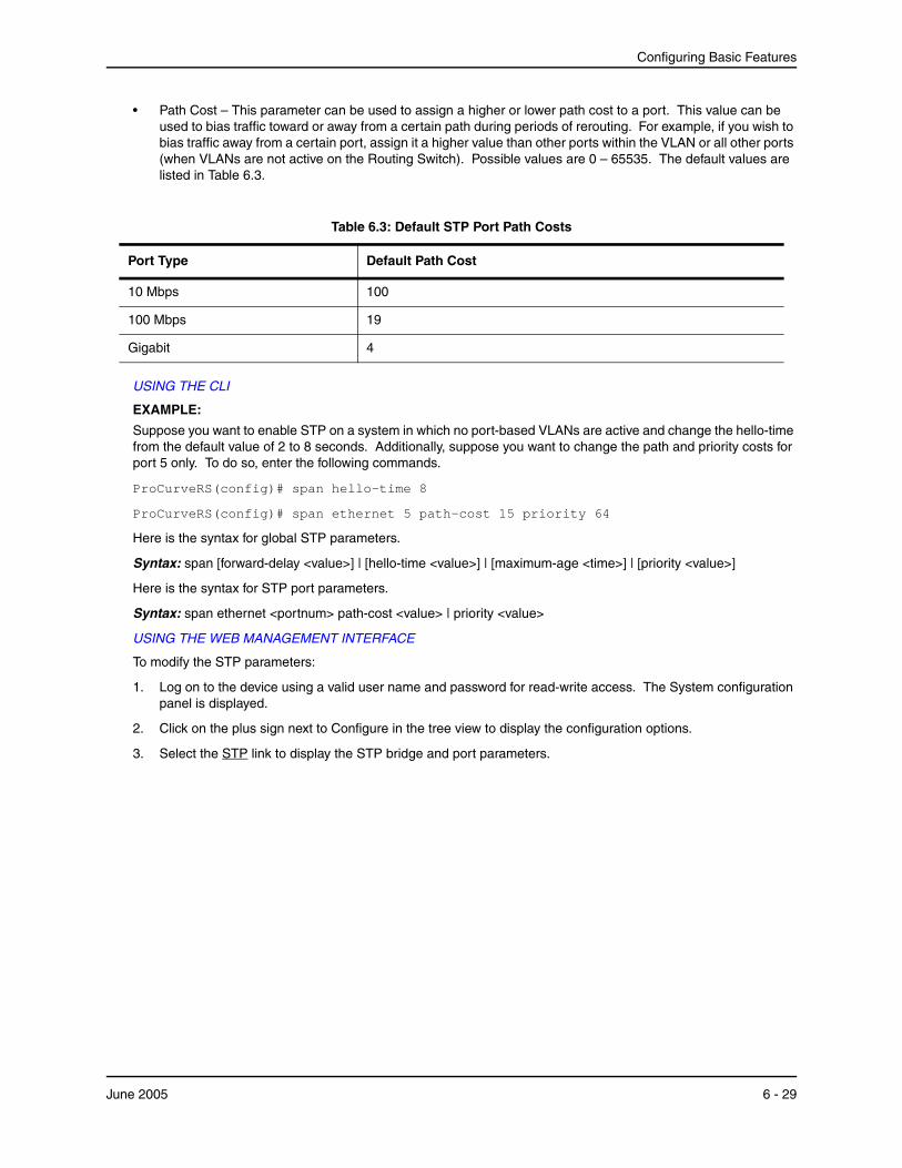
Configuring Basic Features
• Path Cost – This parameter can be used to assign a higher or lower path cost to a port. This value can be used to bias traffic toward or away from a certain path during periods of rerouting. For example, if you wish to bias traffic away from a certain port, assign it a higher value than other ports within the VLAN or all other ports (when VLANs are not active on the Routing Switch). Possible values are 0 – 65535. The default values are listed in Table 6.3.
Table 6.3: Default STP Port Path Costs
Port Type Default Path Cost
10 Mbps 100
100 Mbps 19
Gigabit 4
USING THE CLI
EXAMPLE:
Suppose you want to enable STP on a system in which no port-based VLANs are active and change the hello-time from the default value of 2 to 8 seconds. Additionally, suppose you want to change the path and priority costs for port 5 only. To do so, enter the following commands.
ProCurveRS(config)# span hello-time 8
ProCurveRS(config)# span ethernet 5 path-cost 15 priority 64
Here is the syntax for global STP parameters.
Syntax: span [forward-delay <value>] | [hello-time <value>] | [maximum-age <time>] | [priority <value>]
Here is the syntax for STP port parameters.
Syntax: span ethernet <portnum> path-cost <value> | priority <value>
USING THE WEB MANAGEMENT INTERFACE
To modify the STP parameters:
1. Log on to the device using a valid user name and password for read-write access. The System configuration panel is displayed.
2. Click on the plus sign next to Configure in the tree view to display the configuration options.
3. Select the STP link to display the STP bridge and port parameters.
June 2005 6 - 29
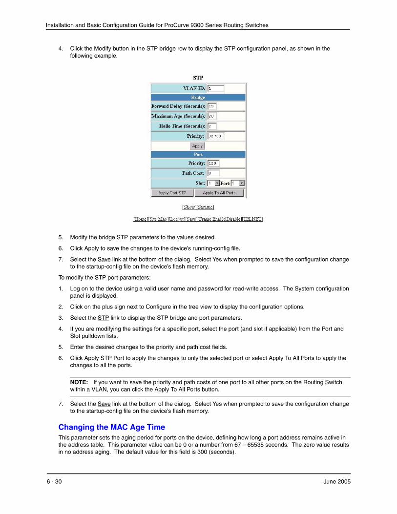
Installation and Basic Configuration Guide for ProCurve 9300 Series Routing Switches
4. Click the Modify button in the STP bridge row to display the STP configuration panel, as shown in the following example.
5. Modify the bridge STP parameters to the values desired.
6. Click Apply to save the changes to the device’s running-config file.
7. Select the Save link at the bottom of the dialog. Select Yes when prompted to save the configuration change to the startup-config file on the device’s flash memory.
To modify the STP port parameters:
1. Log on to the device using a valid user name and password for read-write access. The System configuration panel is displayed.
2. Click on the plus sign next to Configure in the tree view to display the configuration options.
3. Select the STP link to display the STP bridge and port parameters.
4. If you are modifying the settings for a specific port, select the port (and slot if applicable) from the Port and Slot pulldown lists.
5. Enter the desired changes to the priority and path cost fields.
6. Click Apply STP Port to apply the changes to only the selected port or select Apply To All Ports to apply the changes to all the ports.
NOTE: If you want to save the priority and path costs of one port to all other ports on the Routing Switch within a VLAN, you can click the Apply To All Ports button.
7. Select the Save link at the bottom of the dialog. Select Yes when prompted to save the configuration change to the startup-config file on the device’s flash memory.
Changing the MAC Age TimeThis parameter sets the aging period for ports on the device, defining how long a port address remains active in the address table. This parameter value can be 0 or a number from 67 – 65535 seconds. The zero value results in no address aging. The default value for this field is 300 (seconds).
6 - 30 June 2005
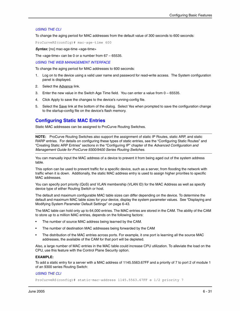
Configuring Basic Features
USING THE CLI
To change the aging period for MAC addresses from the default value of 300 seconds to 600 seconds:
ProCurveRS(config)# mac-age-time 600
Syntax: [no] mac-age-time <age-time>
The <age-time> can be 0 or a number from 67 – 65535.
USING THE WEB MANAGEMENT INTERFACE
To change the aging period for MAC addresses to 600 seconds:
1. Log on to the device using a valid user name and password for read-write access. The System configuration panel is displayed.
2. Select the Advance link.
3. Enter the new value in the Switch Age Time field. You can enter a value from 0 – 65535.
4. Click Apply to save the changes to the device’s running-config file.
5. Select the Save link at the bottom of the dialog. Select Yes when prompted to save the configuration change to the startup-config file on the device’s flash memory.
Configuring Static MAC EntriesStatic MAC addresses can be assigned to ProCurve Routing Switches.
NOTE: ProCurve Routing Switches also support the assignment of static IP Routes, static ARP, and static RARP entries. For details on configuring these types of static entries, see the “Configuring Static Routes” and “Creating Static ARP Entries” sections in the “Configuring IP” chapter of the Advanced Configuration and Management Guide for ProCurve 9300/9400 Series Routing Switches.
You can manually input the MAC address of a device to prevent it from being aged out of the system address table.
This option can be used to prevent traffic for a specific device, such as a server, from flooding the network with traffic when it is down. Additionally, the static MAC address entry is used to assign higher priorities to specific MAC addresses.
You can specify port priority (QoS) and VLAN membership (VLAN ID) for the MAC Address as well as specify device type of either Routing Switch or host.
The default and maximum configurable MAC table sizes can differ depending on the device. To determine the default and maximum MAC table sizes for your device, display the system parameter values. See “Displaying and Modifying System Parameter Default Settings” on page 6-43.
The MAC table can hold only up to 64,000 entries. The MAC entries are stored in the CAM. The ability of the CAM to store up to a million MAC entries, depends on the following factors:
• The number of source MAC address being learned by the CAM.
• The number of destination MAC addresses being forwarded by the CAM
• The distribution of the MAC entries across ports. For example, it one port is learning all the source MAC addresses, the available of the CAM for that port will be depleted.
Also, a large number of MAC entries in the MAC table could increase CPU utilization. To alleviate the load on the CPU, use this feature with the Control Plane Security option.
EXAMPLE:
To add a static entry for a server with a MAC address of 1145.5563.67FF and a priority of 7 to port 2 of module 1 of an 9300 series Routing Switch:
USING THE CLI
ProCurveRS(config)# static-mac-address 1145.5563.67FF e 1/2 priority 7
June 2005 6 - 31
Installation and Basic Configuration Guide for ProCurve 9300 Series Routing Switches
Syntax: [no] static-mac-address <mac-addr> ethernet <portnum> [to <portnum> ethernet <portnum>] [priority <number>] [host-type | router-type | fixed-host]
The priority can be 0 – 7 (0 is lowest priority and 7 is highest priority).
The default priority is 0. The default type is host-type.
NOTE: The location of the static-mac-address command in the CLI depends on whether you configure port-based VLANs on the device. If the device does not have more than one port-based VLAN (VLAN 1, which is the default VLAN that contains all the ports), the static-mac-address command is at the global CONFIG level of the CLI. If the device has more than one port-based VLAN, then the static-mac-address command is not available at the global CONFIG level. In this case, the command is available at the configuration level for each port-based VLAN.
USING THE WEB MANAGEMENT INTERFACE
1. Log on to the device using a valid user name and password for read-write access. The System configuration panel is displayed.
2. Click on the plus sign next to Configure in the tree view to display the list of configuration options.
3. Select the Static Station link.
• If the system already contains static MAC addresses and you are adding a new static MAC address, click on the Add Static Station link to display the Static Station Table configuration panel, as shown in the following example.
• If you are modifying an existing static MAC address, click on the Modify button to the right of the row describing the static MAC address to display the Static Station Table configuration panel, as shown in the following example.
4. Enter or edit the MAC address, if needed. Specify the address in the following format: xx-xx-xx-xx-xx-xx.
5. Change the VLAN number if needed by editing the value in the VLAN ID field.
6. Select the port number from the Slot and Port pulldown lists.
7. Select a QoS level from 0 – 7 from the QoS field’s pulldown menu. For information about QoS, see the “Configuring Quality of Service” chapter in the Advanced Configuration and Management Guide for ProCurve 9300/9400 Series Routing Switches.
8. Click the Add button (to add a new static MAC entry) or the Modify button (if you are modifying an existing entry) to save the change to the device’s running-config file.
9. Click the Apply button to save the change to the device’s running-config file.
10. Select the Save link at the bottom of the dialog, then select Yes when prompted to save the configuration change to the startup-config file on the device’s flash memory.
6 - 32 June 2005
Configuring Basic Features
Configuring Static ARP Entries
HP recommends that you configure a static ARP entry to match the static MAC entry. In fact, the software automatically creates a static MAC entry when you create a static ARP entry.
NOTE: When a static MAC entry has a corresponding static ARP entry, you cannot delete the static MAC entry unless you first delete the static ARP entry.
To create a static ARP entry for a static MAC entry, enter a command such as the following:
ProCurveRS(config)# arp 1 192.53.4.2 aaaa.bbbb.cccc ethernet 1
The arp command allows you to specify only one port number. To create a static ARP entry for a static MAC entry that is associated with multiple ports, specify the first (lowest-numbered) port associated with the static MAC entry.
Syntax: [no] arp <num> <ip-addr> <mac-addr> ethernet <portnum>
The <num> parameter specifies the entry number.
Enabling Port-Based VLANsPort and protocol VLANs must first be enabled at the system (global) level before they can be configured at the VLAN level. For details on configuring VLANs, refer to “Configuring Virtual LANs (VLANs)” in the Advanced Configuration and Management Guide for ProCurve 9300/9400 Series Routing Switches.
USING THE CLI
When using the CLI, port and protocol-based VLANs are created by entering one of the following commands at the global CONFIG level of the CLI.
To create a port-based VLAN, enter commands such as the following:
ProCurveRS(config)# vlan 222 by port
ProCurveRS(config)# vlan 222 name Mktg
Syntax: vlan <num> by port
Syntax: vlan <num> name <string>
The <num> parameter specifies the VLAN ID. The valid range for VLAN IDs starts at 1 on all systems but the upper limit of the range differs depending on the device. In addition, you can change the upper limit on some devices using the vlan max-vlans... command. See the Command Line Interface Reference for ProCurve 9300/9400 Series Routing Switches.
The <string> parameter is the VLAN name and can be a string up to 16 characters. You can use blank spaces in the name if you enclose the name in double quotes (for example, “Product Marketing”.)
NOTE: The second command is optional and also creates the VLAN if the VLAN does not already exist. You can enter the first command after you enter the second command if you first exit to the global CONFIG level of the CLI.
USING THE WEB MANAGEMENT INTERFACE
To enable port-based VLANs on the Routing Switch:
1. Log on to the device using a valid user name and password for read-write access. The System configuration panel is displayed.
2. Click the box for Port, next to Policy Based VLANs to enable port-based VLANs.
3. Click Apply to save the changes to the device’s running-config file.
4. Select the Save link at the bottom of the dialog. Select Yes when prompted to save the configuration change to the startup-config file on the device’s flash memory.
June 2005 6 - 33
Installation and Basic Configuration Guide for ProCurve 9300 Series Routing Switches
Assigning IEEE 802.1q Tagging to a Port
When a port is tagged, it allows communication among the different VLANs to which it is assigned. A common use for this might be to place an email server that multiple groups may need access to on a tagged port, which in turn, is resident in all VLANs that need access to the server.
NOTE: Tagging is disabled by default on individual ports.
NOTE: Tagging does not apply to the default VLAN.
For details on configuring port-based VLANs, refer to “Configuring Virtual LANs (VLANs)” in the Advanced Configuration and Management Guide for ProCurve 9300/9400 Series Routing Switches.
USING THE CLI
When using the CLI, ports are defined as either tagged or untagged at the VLAN level.
EXAMPLE:
Suppose you want to make port 5 on module 1 a member of port-based VLAN 4, a tagged port. To do so, enter the following:
ProCurveRS(config)# vlan 4
ProCurveRS(config-vlan-4)# tagged e 1/5
Syntax: tagged ethernet <portnum> [to <portnum> [ethernet <portnum>]]
USING THE WEB MANAGEMENT INTERFACE
To apply 802.1q tagging to a port:
1. Log on to the device using a valid user name and password for read-write access. The System configuration panel is displayed.
2. Click on the plus sign next to Configure in the tree view to display the configuration options.
3. Click on the plus sign next to Port in the tree view to display the configuration options.
4. Select the link to the port type you want (for example, Ethernet) to display the Port table.
5. Click on the Modify button next to the row of information for the port you want to reconfigure.
6. Select Enable next to IEEE Tagging.
NOTE: This option appears only if you are modifying a port that is a member of a port-based VLAN other than the default VLAN. Tagging does not apply to ports that are not in a port-based VLAN and does not apply to the default VLAN.
7. Click Apply to save the changes to the device’s running-config file.
8. Select the Save link at the bottom of the dialog. Select Yes when prompted to save the configuration change to the startup-config file on the device’s flash memory.
Defining MAC Address FiltersMAC layer filtering enables you to build access lists based on MAC layer headers in the Ethernet/IEEE 802.3 frame. You can filter on the source and destination MAC addresses as well as other information such as the EtherType, LLC1 DSAP or SSAP numbers, and a SNAP EtherType. The filters apply to incoming traffic only.
NOTE: MAC filters do not block management access to the HP device. For example, if you apply a filter to block a specific host, the filter blocks switch traffic from the host but does not prevent the host from establishing a management connection to the device through Telnet. To block management access, use an Access Control List (ACL). See the “IP Access Control Lists (ACLs)“ chapter of the Advanced Configuration and Management Guide for ProCurve 9300/9400 Series Routing Switches.
6 - 34 June 2005
Configuring Basic Features
NOTE: You cannot use Layer 2 filters to filter Layer 4 information. To filter Layer 4 information, use IP access policies. See the “Policies and Filters” appendix in the Advanced Configuration and Management Guide for ProCurve 9300/9400 Series Routing Switches.
You configure MAC filters globally, then apply them to individual interfaces. To apply MAC filters to an interface, you add the filters to that interface’s MAC filter group.
NOTE: In software release 07.6.04, you can apply MAC filters to virtual routing interfaces. For more information, see “Configuring MAC Address Filters for Virtual Routing Ports” on page 6-39.
The device takes the action associated with the first matching filter. If the packet does not match any of the filters in the access list, the default action is to drop the packet. If you want the system to permit traffic by default, you must specifically indicate this by making the last entry in the access list a permit filter. Here is an example: mac filter <last-index-number> permit any any
For Routing Switches, the MAC filter is applied only to those inbound packets that are to be switched. This includes those ports associated with a virtual routing interface. However, the filter is not applied to the virtual routing interface. It is applied to the physical port.
NOTE: Inbound traffic on a port to which a Layer 2 MAC filter is assigned is sent to the CPU for processing.
NOTE: Use MAC Layer 2 filters only for switched traffic. If a routing protocol (for example, IP or IPX) is configured on an interface, a MAC filter defined on that interface is not applied to inbound packets. If you want to filter inbound route traffic, configure a route filter.
When you create a MAC filter, it takes effect immediately. You do not need to reset the system. However, you do need to save the configuration to flash memory to retain the filters across system resets.
For complete MAC filter examples, see the Command Line Interface Reference for ProCurve 9300/9400 Series Routing Switches.
Configuring MAC Address Filters for Physical Ports
NOTE: In software releases 07.6.04 and later, you can apply MAC filters to virtual routing interfaces. For more information, see “Configuring MAC Address Filters for Virtual Routing Ports” on page 6-39.
To define a MAC filter, use one of the following methods.
USING THE CLI
To configure and apply a MAC filter, enter commands such as the following:
ProCurveRS(config)# mac filter 1 deny 3565.3475.3676 ffff.0000.0000 any etype eq 806 ProCurveRS(config)# mac filter 1 permit any any ProCurveRS(config)# int e 1/1 ProCurveRS(config-if-1/1)# mac filter-group 1
These commands configure a filter to deny ARP traffic with a source MAC address that begins with “3565” to any destination. The second filter permits all traffic that is not denied by another filter.
NOTE: Once you apply a MAC filter to a port, the device drops all Layer 2 traffic on the port that does not match a MAC permit filter on the port.
Syntax: mac filter <filter-num> permit | deny any | <H.H.H> any | <H.H.H> etype | IIc | snap <operator> <frame-type>
The <filter-num> can be a number from 1 – 128.
The permit | deny argument determines the action the software takes when a match occurs.
June 2005 6 - 35

Installation and Basic Configuration Guide for ProCurve 9300 Series Routing Switches
The <src-mac> <mask> | any parameter specifies the source MAC address. You can enter a specific address value and a comparison mask or the keyword any to filter on all MAC addresses. Specify the mask using f’s (ones) and zeros. For example, to match on the first two bytes of the address aabb.ccdd.eeff, use the mask ffff.0000.0000. In this case, the filter matches on all MAC addresses that contain "aabb" as the first two bytes. The filter accepts any value for the remaining bytes of the MAC address. If you specify any, do not specify a mask. In this case, the filter matches on all MAC addresses.
The <dest-mac> <mask> | any parameter specifies the destination MAC address. The syntax rules are the same as those for the <src-mac> <mask> | any parameter.
Use the etype | llc | snap argument if you want to filter on information beyond the source and destination address. The MAC filter allows for you to filter on the following encapsulation types:
• etype (Ethertype) – a two byte field indicating the protocol type of the frame. This can range from 0x0600 to 0xFFFF.
• llc (IEEE 802.3 LLC1 SSAP and DSAP) – a two byte sequence providing similar function as the EtherType but for an IEEE 802.3 frame.
• snap (IEEE 802.3 LLC1 SNAP) – a specific LLC1 type packet.
To determine which type of frame is used on your network, use a protocol analyzer. If byte 12 of an Ethernet packet is equal to or greater than 0600 (hex), it is an Ethernet framed packet. Any number below this indicates an IEEE 802.3 frame (byte 12 will now indicate the length of the data field). Some well-known Ethernet types are 0800 (TCP/IP), 0600 (XNS), and 8137 (Novell Netware). Refer to RFC 1042 for a complete listing of EtherTypes.
For IEEE 802.3 frame, you can further distinguish the SSAP and DSAP of LLC header. Some well-known SAPs include: FE (OSI), F0 (NetBIOS), 42 (Spanning Tree BPDU), and AA (SNAP). Usually the DSAP and SSAP are the same.
NOTE: You must type in both bytes, otherwise the software will fill the field, left justified with a 00. Refer to RFC 1042 for a complete listing of SAP numbers.
SNAP is defined as an IEEE 802.3 frame with the SSAP, DSAP, and control field set to AA, AA, and 03. Immediately following these is a five-byte SNAP header. The first three bytes in this header are not used by the MAC filters. However, the next two bytes usually are set to the EtherType, so you can define the EtherType inside the SNAP header that you want to filter on.
The eq | gt | lt | neq argument specifies the possible operator: eq (equal), gt (greater than), lt (less than) and neq (not equal).
The <frame-type> argument is a hexadecimal number for the frame type. For example, the hex number for ARP is 806.
To globally enable logging for filtered packets, enter the following command:
ProCurveRS(config)# mac filter log-enable
Syntax: mac filter log-enable
To enable logging for filtered packets on a specific port, enter the following commands:
ProCurveRS(config)# int e 1/1 ProCurveRS(config-if-1/1)# mac filter-group log-enable
Syntax: mac filter-group log-enable
To assign MAC filter 1 to interface port 1 on slot 1, enter the following commands:
ProCurveRS(config)# int e 1/1 ProCurveRS(config-if-1/1)# mac filter-group 1
Syntax: mac filter-group <filter-list>
NOTE: The filters must be applied as a group. For example, if you want to apply four filters to an interface, they must all appear on the same command line.
6 - 36 June 2005
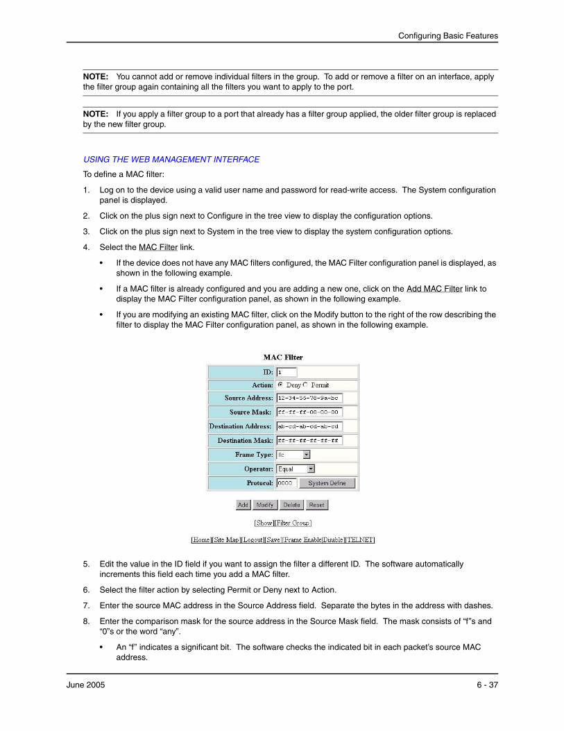
Configuring Basic Features
NOTE: You cannot add or remove individual filters in the group. To add or remove a filter on an interface, apply the filter group again containing all the filters you want to apply to the port.
NOTE: If you apply a filter group to a port that already has a filter group applied, the older filter group is replaced by the new filter group.
USING THE WEB MANAGEMENT INTERFACE
To define a MAC filter:
1. Log on to the device using a valid user name and password for read-write access. The System configuration panel is displayed.
2. Click on the plus sign next to Configure in the tree view to display the configuration options.
3. Click on the plus sign next to System in the tree view to display the system configuration options.
4. Select the MAC Filter link.
• If the device does not have any MAC filters configured, the MAC Filter configuration panel is displayed, as shown in the following example.
• If a MAC filter is already configured and you are adding a new one, click on the Add MAC Filter link to display the MAC Filter configuration panel, as shown in the following example.
• If you are modifying an existing MAC filter, click on the Modify button to the right of the row describing the filter to display the MAC Filter configuration panel, as shown in the following example.
5. Edit the value in the ID field if you want to assign the filter a different ID. The software automatically increments this field each time you add a MAC filter.
6. Select the filter action by selecting Permit or Deny next to Action.
7. Enter the source MAC address in the Source Address field. Separate the bytes in the address with dashes.
8. Enter the comparison mask for the source address in the Source Mask field. The mask consists of “f”s and “0”s or the word “any”.
• An “f” indicates a significant bit. The software checks the indicated bit in each packet’s source MAC address.
June 2005 6 - 37
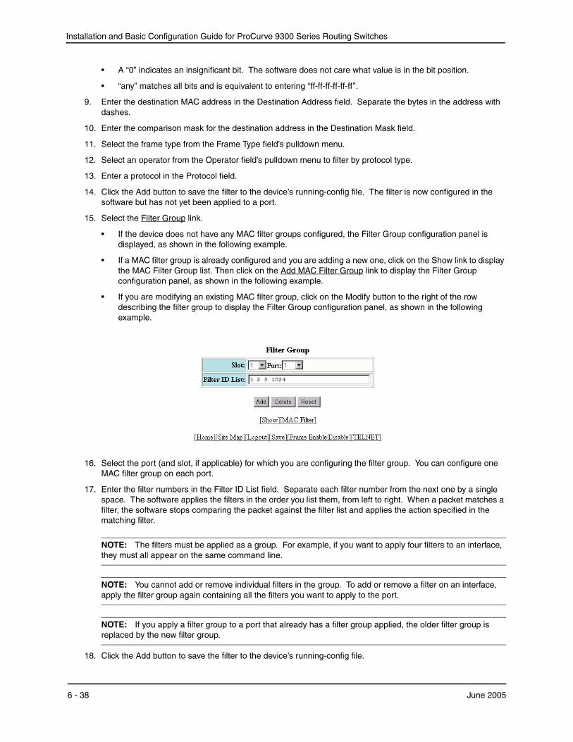
Installation and Basic Configuration Guide for ProCurve 9300 Series Routing Switches
• A “0” indicates an insignificant bit. The software does not care what value is in the bit position.
• “any” matches all bits and is equivalent to entering “ff-ff-ff-ff-ff-ff”.
9. Enter the destination MAC address in the Destination Address field. Separate the bytes in the address with dashes.
10. Enter the comparison mask for the destination address in the Destination Mask field.
11. Select the frame type from the Frame Type field’s pulldown menu.
12. Select an operator from the Operator field’s pulldown menu to filter by protocol type.
13. Enter a protocol in the Protocol field.
14. Click the Add button to save the filter to the device’s running-config file. The filter is now configured in the software but has not yet been applied to a port.
15. Select the Filter Group link.
• If the device does not have any MAC filter groups configured, the Filter Group configuration panel is displayed, as shown in the following example.
• If a MAC filter group is already configured and you are adding a new one, click on the Show link to display the MAC Filter Group list. Then click on the Add MAC Filter Group link to display the Filter Group configuration panel, as shown in the following example.
• If you are modifying an existing MAC filter group, click on the Modify button to the right of the row describing the filter group to display the Filter Group configuration panel, as shown in the following example.
16. Select the port (and slot, if applicable) for which you are configuring the filter group. You can configure one MAC filter group on each port.
17. Enter the filter numbers in the Filter ID List field. Separate each filter number from the next one by a single space. The software applies the filters in the order you list them, from left to right. When a packet matches a filter, the software stops comparing the packet against the filter list and applies the action specified in the matching filter.
NOTE: The filters must be applied as a group. For example, if you want to apply four filters to an interface, they must all appear on the same command line.
NOTE: You cannot add or remove individual filters in the group. To add or remove a filter on an interface, apply the filter group again containing all the filters you want to apply to the port.
NOTE: If you apply a filter group to a port that already has a filter group applied, the older filter group is replaced by the new filter group.
18. Click the Add button to save the filter to the device’s running-config file.
6 - 38 June 2005

Configuring Basic Features
19. Select the Save link at the bottom of the dialog. Select Yes when prompted to save the configuration change to the startup-config file on the device’s flash memory.
Configuring MAC Address Filters for Virtual Routing Ports
Software release 07.6.04 allows you to apply MAC filters to virtual routing interfaces; however, MAC filters used on a virtual routing interface can only deny packets. Permit is not available. Packets are denied based on their source MAC address. The Routing Switch will drop any Layer 2 or Layer 3 packet that originated from the specified source MAC address.
NOTE: No etype arguments will be checked.
To apply a MAC filter on a virtual routing interface using the CLI, first create a filter group that denies specific source MAC addresses using the mac filter-group command. (Refer to theInstallation and Basic Configuration Guide for ProCurve 9300 Series Routing Switches for details.) Then use the mac deny-src-mac-filter-grp... command to apply them to virtual routing interfaces. Enter commands such as the following:
ProCurveRS(config)# interface ve 2 ProCurveRS(config-vif-2)# mac filter 1 deny 00a0.cc77.a18d ffff.ffff.ffff any ProCurveRS(config-vif-2)# mac filter 2 deny 0010.2222.3333 ffff.ffff.ffff any ProCurveRS(config-vif-2)# mac deny-src-mac-filter-grp 1 2
Syntax: [no] mac deny-src-mac-filter-group <number>
<number> is the number of the ID of the filter that you’ve defined. You can enter up to eight filter IDs.
Enabling Logging of Packets Denied by MAC Filters
You can configure the HP device to generate Syslog entries and SNMP traps for packets that are denied by Layer 2 MAC filters. You can enable logging of denied packets on a global basis or an individual port basis.
The first time an entry in a MAC filter denies a packet and logging is enabled for that entry, the software generates a Syslog message and an SNMP trap. Messages for packets denied by MAC filters are at the warning level of the Syslog.
When the first Syslog entry for a packet denied by a MAC filter is generated, the software starts a five-minute MAC filter timer. After this, the software sends Syslog messages every five minutes. The messages list the number of packets denied by each MAC filter during the previous five-minute interval. If a MAC filter does not deny any packets during the five-minute interval, the software does not generate a Syslog entry for that MAC filter.
NOTE: For a MAC filter to be eligible to generate a Syslog entry for denied packets, logging must be enabled for the filter. The Syslog contains entries only for the MAC filters that deny packets and have logging enabled.
When the software places the first entry in the log, the software also starts the five-minute timer for subsequent log entries. Thus, five minutes after the first log entry, the software generates another log entry and SNMP trap for denied packets.
USING THE CLI
To configure Layer 2 MAC filter logging globally, enter the following CLI commands at the global CONFIG level:
ProCurveRS(config)# mac filter log-enable ProCurveRS(config)# write memory
Syntax: [no] mac filter log-enable
To configure Layer 2 MAC filter logging for MAC filters applied to ports 1/1 and 3/3, enter the following CLI commands:
ProCurveRS(config)# int ethernet 1/1 ProCurveRS(config-if-1/1)# mac filter-group log-enable ProCurveRS(config-if-1/1)# int ethernet 3/3 ProCurveRS(config-if-3/3)# mac filter-group log-enable ProCurveRS(config-if-3/3)# write memory
June 2005 6 - 39
Installation and Basic Configuration Guide for ProCurve 9300 Series Routing Switches
Syntax: [no] mac filter-group log-enable
USING THE WEB MANAGEMENT INTERFACE
You cannot configure a Layer 2 MAC filter to generate Syslog entries and SNMP traps for denied packets using the Web management interface.
Defining Broadcast and Multicast FiltersYou can filter Layer 2 broadcast and multicast packets on specific ports.
• Layer 2 broadcast packets have the value “FFFFFFFFFFFF” (all ones) in the destination MAC address field. You can configure broadcast filters for all types of IP packets or for UDP packets.
• Layer 2 multicast packets have a multicast address in the destination MAC address field. You can configure multicast filters to filter on all MAC addresses or a specific multicast address.
You can configure up to eight of each type of filter.
To configure a Layer 2 broadcast or multicast filter, you define the filter globally to either filter out all types of broadcasts or to filter out only IP UDP broadcasts. After configuring a broadcast or multicast filter, you apply it to specific ports. Broadcast and multicast filters apply only to outbound traffic.
When defining the filter, you can specify a port-based VLAN ID. If a port is a member of more than one VLAN and is a tagged port, specifying a VLAN ID causes the filter to be applied only to traffic for the specified VLAN on the tagged ports to which you apply the filter. Otherwise, the filter applies to all the VLANs of which the port is a member.
The filters are applied in numerical order, beginning with filter number 1. As soon as the software finds a matching filter for a given packet, the filtering process stops for that packet. For example, if you configure filter 1 to filter all broadcast traffic and filter 2 to filter only IP UDP traffic, filter 1 will always be true for any broadcast packet, and thus the software will never consult filter 2 for ports that you configure to use filter 1.
Configuring a Layer 2 Broadcast Filter
To configure a broadcast filter, you must have access to the CONFIG level of the CLI. You can configure up to eight broadcast filters on a device.
Syntax: [no] broadcast filter <filter-id> any | ip udp [vlan <vlan-id>]
Syntax: [no] exclude-ports ethernet <portnum> to <portnum>
Or
Syntax: [no] exclude-ports ethernet <portnum> ethernet <portnum>
The exclude-ports command specifies the ports to which the filter applies.
The <filter-id> specifies the filter number and can a number from 1 – 8. The software applies the filters in ascending numerical order. As soon as a match is found, the software takes the action specified by the filter (block the broadcast) does not compare the packet against additional broadcast filters.
You can specify any or ip udp as the type of broadcast traffic to filter. The any parameter prevents all broadcast traffic from being sent on the specified ports. The ip udp parameter prevents all IP UDP broadcasts from being sent on the specified ports but allows other types of broadcast traffic.
If you specify a port-based VLAN ID, the filter applies only to the broadcast domain of the specified VLAN, not to all broadcast domains (VLANs) on the device.
As soon as you press Enter after entering the command, the CLI changes to the configuration level for the filter you are configuring. You specify the ports to which the filter applies at the filter's configuration level.
NOTE: This is the same command syntax as that used for configuring port-based VLANs. Use the first command for adding a range of ports. Use the second command for adding separate ports (not in a range). You also can combine the syntax. For example, you can enter exclude-ports ethernet 1/4 ethernet 2/6 to 2/9.
6 - 40 June 2005
Configuring Basic Features
Configuration ExamplesTo configure a Layer 2 broadcast filter to filter all types of broadcasts, then apply the filter to ports 1/1, 1/2, and 1/3, enter the following commands:
ProCurveRS(config)# broadcast filter 1 any
ProCurveRS(config-bcast-filter-id-1)# exclude-ports ethernet 1/1 to 1/3
ProCurveRS(config-bcast-filter-id-1)# write memory
To configure two filters, one to filter IP UDP traffic on ports 1/1 – 1/4, and the other to filter all broadcast traffic on port 4/6, enter the following commands:
ProCurveRS(config)# broadcast filter 2 ip udp
ProCurveRS(config-bcast-filter-id-2)# exclude-ports ethernet 1/1 to 1/4
ProCurveRS(config-bcast-filter-id-2)# exit
ProCurveRS(config)# broadcast filter 3 any
ProCurveRS(config-bcast-filter-id-3)# exclude-ports ethernet 4/6
ProCurveRS(config-bcast-filter-id-3)# write memory
To configure an IP UDP broadcast filter and apply that applies only to port-based VLAN 10, then apply the filter to two ports within the VLAN, enter the following commands:
ProCurveRS(config)# broadcast filter 4 ip udp vlan 10
ProCurveRS(config-bcast-filter-id-4)# exclude-ports eth 1/1 eth 1/3
ProCurveRS(config-bcast-filter-id-4)# write memory
Configuring a Layer 2 Multicast Filter
To configure a multicast filter, you must have access to the CONFIG level of the CLI. You can configure up to eight multicast filters on a device.
Syntax: [no] multicast filter <filter-id> any | ip udp mac <multicast-address> | any [mask <mask>] [vlan <vlan-id>]
The parameter values are the same as the for the broadcast filter command. In addition, the multicast filter command requires the mac <multicast-address> | any parameter, which specifies the multicast address. Enter mac any to filter on all multicast addresses.
Enter mac followed by a specific multicast address to filter only on that multicast address. To filter on a range of multicast addresses, use the mask <mask> parameter. For example, to filter on multicast groups 0100.5e00.5200 – 0100.5e00.52ff, use mask ffff.ffff.ff00. The default mask matches all bits (is all Fs). You can leave the mask off if you want the filter to match on all bits in the multicast address.
Configuration ExamplesTo configure a Layer 2 multicast filter to filter all multicast groups, then apply the filter to ports 2/4, 2/5, and 2/8, enter the following commands:
ProCurveRS(config)# multicast filter 1 any
ProCurveRS(config-mcast-filter-id-1)# exclude-ports ethernet 2/4 to 2/5 ethernet 2/8
ProCurveRS(config-mcast-filter-id-1)# write memory
To configure a multicast filter to block all multicast traffic destined for multicast addresses 0100.5e00.5200 – 0100.5e00.52ff on port 4/8, enter the following commands:
ProCurveRS(config)# multicast filter 2 any 0100.5e00.5200 mask ffff.ffff.ff00
ProCurveRS(config-mcast-filter-id-2)# exclude-ports ethernet 4/8
ProCurveRS(config-mcast-filter-id-2)# write memory
June 2005 6 - 41

Installation and Basic Configuration Guide for ProCurve 9300 Series Routing Switches
The software calculates the range by combining the mask with the multicast address. In this example, all but the last eight bits in the mask are “significant bits” (ones). The last eight bits are zeros and thus match on any value. Each “f” or “0” is four bits.
Locking a Port To Restrict AddressesAddress-lock filters allow you to limit the number of devices that have access to a specific port. Access violations are reported as SNMP traps. By default this feature is disabled. A maximum of 2048 entries can be specified for access. The default address count is eight.
NOTE: In release 07.6.04, a more robust version of this feature was introduced. See “Using the MAC Port Security Feature” in the Security Guide for ProCurve 9300/9400 Series Routing Switches.
USING THE CLI
EXAMPLE:
To enable address locking for port 2/1 and place a limit of 15 entries:
ProCurveRS(config)# lock e 2/1 addr 15
Syntax: lock-address ethernet <portnum> [addr-count <num>]
USING THE WEB MANAGEMENT INTERFACE
To enable address locking on a port:
1. Log on to the device using a valid user name and password for read-write access. The System configuration panel is displayed.
2. Click on the plus sign next to Configure in the tree view to display the configuration options.
3. Click on the plus sign next to Port in the tree view to display the configuration options.
4. Select the link to the port type you want (for example, Ethernet) to display the Port table.
5. Click on the Modify button next to the row of information for the port you want to reconfigure.
6. Select Enable next to Lock Address.
7. Enter the maximum number of MAC addresses you want the device to learn on the port in the MAC Address field.
8. Click Apply to save the changes to the device’s running-config file.
9. Select the Save link at the bottom of the dialog. Select Yes when prompted to save the configuration change to the startup-config file on the device’s flash memory.
Enabling or Disabling Routing ProtocolsProCurve Routing Switches support the following protocols:
• AppleTalk
• BGP4
• DVMRP
• IP
• IPX
• OSPF
• PIM
• RIP
• VRRP
6 - 42 June 2005
Configuring Basic Features
• VRRPE
By default, IP routing is enabled on Routing Switches. All other protocols are disabled, so you must enable them to configure and use them.
NOTE: The following protocols require a system reset before the protocol will be active on the system: PIM, DVMRP, RIP, and IPX. To reset a system, select the Reload link (Web) or enter the reload command at the privileged level of the CLI.
USING THE CLI
To enable a protocol on a ProCurve Routing Switch, enter Routing Switch at the global CONFIG level, followed by the protocol to be enabled. The following example shows how to enable OSPF:
ProCurveRS(config)# router ospf
ProCurveRS(config)# end
ProCurveRS# write memory
ProCurveRS# reload
Syntax: router appletalk | bgp | dvmrp | ipx | ospf | pim | rip | vrrp | vrrpe
USING THE WEB MANAGEMENT INTERFACE
To enable protocols on a Routing Switch:
1. Log on to the device using a valid user name and password for read-write access. The System configuration panel is displayed.
2. Select the Enable option next to the protocol(s) to be enabled.
NOTE: If you are enabling BGP4, you must also specify the local AS number in the Local AS field.
3. Click Apply to save the changes to the device’s running-config file.
4. Select the Save link at the bottom of the dialog. Select Yes when prompted to save the configuration change to the startup-config file on the device’s flash memory.
NOTE: You also can access the dialog for saving configuration changes by clicking on Command in the tree view, then clicking on Save to Flash.
If you enable PIM, DVMRP, RIP, or IPX, you must reload the software to place the change into effect.
1. Click on the plus sign next to Command in the tree view to list the command options.
2. Select the Reload link and select Yes when the Web management interface asks you whether you really want to reload the software.
Displaying and Modifying System Parameter Default SettingsHP devices have default table sizes for the following parameters. The table sizes determine the maximum number of entries the tables can hold. You can adjust individual table sizes to accommodate your configuration needs.
• MAC address entries
• Layer 2 Port VLANs supported on a system
• Layer 3 Protocol VLANs supported on a system
• Layer 4 sessions supported
• IP cache size
• ARP entries
June 2005 6 - 43
Installation and Basic Configuration Guide for ProCurve 9300 Series Routing Switches
• IP routes
• IP route filters
• IP subnets per port and per device
• Static routes
• IGMP
• DVMRP routes
• IPX/SAP entries
• IPX/RIP entries
• IPX/SAP filters
• IPX/RIP filters
• IPX forwarding filters
• AppleTalk routes
• AppleTalk zones
The tables you can configure as well the defaults and valid ranges for each table differ depending on the HP device you are configuring.
NOTE: If you increase the number of subnet addresses you can configure on each port to a higher amount, you might also need to increase the total number of subnets that you can configure on the device.
To display and configure the adjustable tables on a device, use one of the following methods.
NOTE: Changing the table size for a parameter reconfigures the device’s memory. Whenever you reconfigure the memory on an HP device, you must save the change to the startup-config file, then reload the software to place the change into effect.
6 - 44 June 2005

Configuring Basic Features
USING THE CLI
To display the configurable tables and their defaults and maximum values, enter the following command at any level of the CLI:
ProCurveRS# show default values
sys log buffers:50 mac age time:300 sec telnet sessions:5 ip arp age:10 min bootp relay max hops:4 ip ttl:64 hops ip addr per intf:24 when multicast enabled : igmp group memb.:140 sec igmp query:60 sec when ospf enabled : ospf dead:40 sec ospf hello:10 sec ospf retrans:5 sec ospf transit delay:1 sec when bgp enabled : bgp local pref.:100 bgp keep alive:60 sec bgp hold:180 sec bgp metric:10 bgp local as:1 bgp cluster id:0 bgp ext. distance:20 bgp int. distance:200 bgp local distance:200 System Parameters Default Maximum Current ip-arp 8000 64000 8000 ip-static-arp 1024 2048 1024 atalk-route 512 1536 512 atalk-zone-port 64 255 64 atalk-zone-sys 255 1024 255 dvmrp 2048 32000 2048 igmp 256 1024 256 ip-cache 128000 256000 128000 ip-filter-port 512 4096 512 ip-filter-sys 1024 8192 1024 ipx-forward-filter 256 1024 256 ipx-rip-entry 3072 32728 3072 ipx-rip-filter 256 1024 256 ipx-sap-entry 6144 32768 6144 ipx-sap-filter 256 1024 256 l3-vlan 32 2048 32 ip-qos-session 2048 32000 2048 l4-real-server 1024 2048 1024 l4-virtual-server 256 512 256 l4-server-port 2048 4096 2048 mac 8000 64000 8000 ip-route 128000 200000 128000 ip-static-route 512 2048 512 vlan 16 2048 16 spanning-tree 32 128 32 mac-filter-port 32 512 32 mac-filter-sys 64 1024 64 ip-subnet-port 24 128 24 session-limit 131072 500000 131072 view 10 65535 10 virtual-interface 255 2048 255
June 2005 6 - 45
Installation and Basic Configuration Guide for ProCurve 9300 Series Routing Switches
Information for the configurable tables appears under the columns that are shown in bold type in this example. To simplify configuration, the command parameter you enter to configure the table is used for the table name. For example, to increase the capacity of the IP route table, enter the following commands:
ProCurveRS(config)# system-max ip-route 120000
ProCurveRS(config)# write memory
ProCurveRS(config)# exit
ProCurveRS# reload
NOTE: If you accidentally enter a value that is not within the valid range of values, the CLI will display the valid range for you.
To increase the number of IP subnet interfaces you can configure on each port on a Routing Switch from 24 to 64, then increase the total number of IP interfaces you can configure on the device from 256 to 512, enter the following commands:
ProCurveRS(config)# system-max subnet-per-interface 64 ProCurveRS(config)# write memory ProCurveRS(config)# exit ProCurveRS# reload
Syntax: system-max subnet-per-interface <num>
The <num> parameter specifies the maximum number of subnet addresses per port and can be from 1 – 64. The default is 24.
Syntax: system-max subnet-per-system <num>
The <num> parameter specifies the maximum number of subnet addresses for the entire device and can be from 1 – 512. The default is 256.
ProCurveRS(config)# system-max subnet-per-system 512 ProCurveRS(config)# write memory ProCurveRS(config)# exit ProCurveRS# reload
USING THE WEB MANAGEMENT INTERFACE
To modify a table size using the Web management interface:
1. Log on to the device using a valid user name and password for read-write access. The System configuration panel is displayed.
2. Select the Max-Parameter link to display the Configure System Parameter Maximum Value table. This table lists the settings and valid ranges for all the configurable table sizes on the device.
3. Click the Modify button next to the row for the table you want to change.
4. Enter the new value for the table size. The value you enter specifies the maximum number of entries the table can hold.
5. Click Apply to save the changes to the device’s running-config file.
6. Select the Save link at the bottom of the dialog. Select Yes when prompted to save the configuration change to the startup-config file on the device’s flash memory.
7. Click on the plus sign next to Command in the tree view to list the command options.
8. Select the Reload link and select Yes when the Web management interface asks you whether you really want to reload the software. Changes to table sizes do not take effect until you reload the software.
6 - 46 June 2005

Configuring Basic Features
Using the Temperature SensorThe following products and modules have a temperature sensor:
• T-Flow Redundant Management Module
• Management Modules 2 and 4
The redundant management modules contain a temperature sensor. The temperature sensor generates a Syslog message and SNMP trap if the temperature exceeds a specified warning level or shutdown level, and can shut the module down if the temperature exceeds the safe threshold. You can use the CLI or Web management interface to display the temperature and to change the warning and shutdown temperature levels. The software reads the temperature sensor according to the chassis poll time, which is 60 seconds by default.
If the temperature equals or exceeds the shutdown temperature for five consecutive polls of the temperature by the software, the software shuts down the module to prevent damage.
You can display the temperature of the module. You also can change the warning and shutdown temperatures and the chassis poll time.
Displaying the TemperatureBy default, the software polls the temperature sensor on the module every 60 seconds to get the current temperature. This poll rate is controlled by the chassis poll time, which also controls how often the software polls other system components. You can display the temperature of the module using either of the following methods.
USING THE CLI
To display the temperature of a module, enter the following command at any level of the CLI:
ProCurveRS> show chassis
power supply 1 not present power supply 2 not present power supply 3 ok power supply 4 not present power supply 1 to 4 from bottom to top fan 1 ok fan 2 bad fan 3 ok fan 4 ok Current temperature : 34.5 C degrees Warning level : 45 C degrees, shutdown level : 55 C degrees
Syntax: show chassis
USING THE WEB MANAGEMENT INTERFACE
1. Log on to the device using a valid user name and password for read-write access. The System configuration dialog is displayed.
2. Click on the plus sign next to Monitor in the tree view to display the monitoring options.
3. Select the Device link to display the Device Information panel. The temperature is listed in the Temperature field. The temperature information is color coded to indicate the state.
• Green indicates the temperature is within the normal operating range.
• Orange indicates the temperature has reached the warning level.
• Red indicates the temperature has reached the shutdown level.
NOTE: You also can display the Device Information panel by clicking on the graphic of the chassis panel, in the upper right frame. The graphic is shown only if the Web management interface frames are enabled.
June 2005 6 - 47
Installation and Basic Configuration Guide for ProCurve 9300 Series Routing Switches
Displaying Temperature MessagesThe software sends a Syslog message and an SNMP trap if the temperature crosses the warning or shutdown thresholds. The following methods describe how to view the system log on the device. If you have configured the device to use a Syslog server or SNMP trap receiver, see the documentation for the server or receiver.
USING THE CLI
To display the system log, enter the following command at any CLI level:
ProCurveRS# show log
Syslog logging: enabled (0 messages dropped, 0 flushes, 0 overruns) Buffer logging: level ACDMEINW, 8 messages logged level code: A=alert C=critical D=debugging M=emergency E=error I=informational N=notification W=warning Static Log Buffer: Dynamic Log Buffer (50 entries): at 0 days 0 hours 2 minutes 0 seconds, level alert Temperature 48.0 C degrees, warning level 45.0 C degrees, shutdown level 55.0 C degrees at 0 days 0 hours 1 minutes 0 seconds, level alert Temperature 50.0 C degrees, warning level 45.0 C degrees, shutdown level 55.0 C degrees
USING THE WEB MANAGEMENT INTERFACE
1. Log on to the device using a valid user name and password for read-write access. The System configuration dialog is displayed.
2. Click on the plus sign next to Monitor in the tree view to display the Monitor options.
3. Select the System Log link to display the system log.
Changing Temperature Warning and Shutdown LevelsThe default warning temperature is 45.0 C degrees. The default shutdown temperature is 55.0 C degrees. You can change the warning and shutdown temperatures using the following commands. The valid range for each value is 0 – 125 C degrees.
NOTE: You cannot set the warning temperature to a value higher than the shutdown temperature.
USING THE CLI
To change the temperature at which the module sends a warning, enter a command such as the following at the Privileged EXEC level of the CLI:
ProCurveRS# temperature warning 47
Syntax: temperature warning <value>
The <value> can be 0 – 125.
To change the shutdown temperature, enter a command such as the following at Privileged EXEC level of the CLI:
ProCurveRS# temperature shutdown 57
Syntax: temperature shutdown <value>
The <value> can be 0 – 125.
6 - 48 June 2005
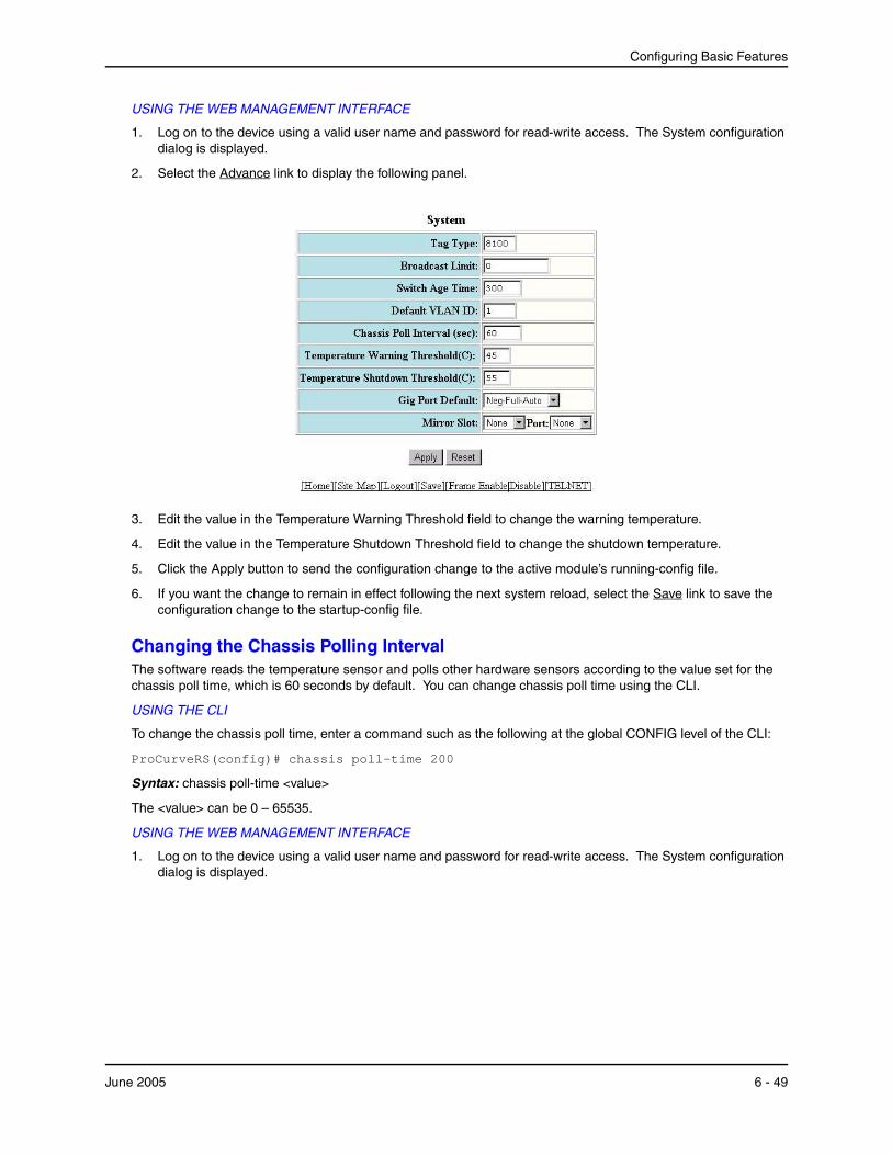
Configuring Basic Features
USING THE WEB MANAGEMENT INTERFACE
1. Log on to the device using a valid user name and password for read-write access. The System configuration dialog is displayed.
2. Select the Advance link to display the following panel.
3. Edit the value in the Temperature Warning Threshold field to change the warning temperature.
4. Edit the value in the Temperature Shutdown Threshold field to change the shutdown temperature.
5. Click the Apply button to send the configuration change to the active module’s running-config file.
6. If you want the change to remain in effect following the next system reload, select the Save link to save the configuration change to the startup-config file.
Changing the Chassis Polling IntervalThe software reads the temperature sensor and polls other hardware sensors according to the value set for the chassis poll time, which is 60 seconds by default. You can change chassis poll time using the CLI.
USING THE CLI
To change the chassis poll time, enter a command such as the following at the global CONFIG level of the CLI:
ProCurveRS(config)# chassis poll-time 200
Syntax: chassis poll-time <value>
The <value> can be 0 – 65535.
USING THE WEB MANAGEMENT INTERFACE
1. Log on to the device using a valid user name and password for read-write access. The System configuration dialog is displayed.
June 2005 6 - 49
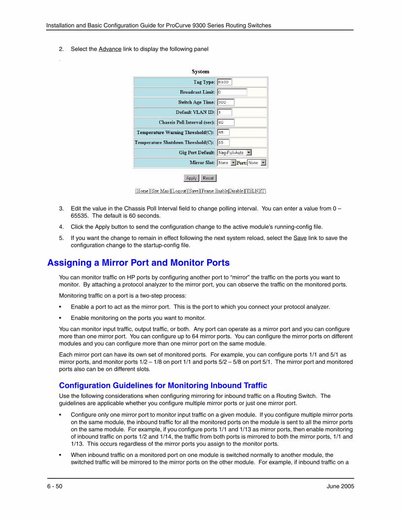
Installation and Basic Configuration Guide for ProCurve 9300 Series Routing Switches
2. Select the Advance link to display the following panel
.
3. Edit the value in the Chassis Poll Interval field to change polling interval. You can enter a value from 0 – 65535. The default is 60 seconds.
4. Click the Apply button to send the configuration change to the active module’s running-config file.
5. If you want the change to remain in effect following the next system reload, select the Save link to save the configuration change to the startup-config file.
Assigning a Mirror Port and Monitor PortsYou can monitor traffic on HP ports by configuring another port to “mirror” the traffic on the ports you want to monitor. By attaching a protocol analyzer to the mirror port, you can observe the traffic on the monitored ports.
Monitoring traffic on a port is a two-step process:
• Enable a port to act as the mirror port. This is the port to which you connect your protocol analyzer.
• Enable monitoring on the ports you want to monitor.
You can monitor input traffic, output traffic, or both. Any port can operate as a mirror port and you can configure more than one mirror port. You can configure up to 64 mirror ports. You can configure the mirror ports on different modules and you can configure more than one mirror port on the same module.
Each mirror port can have its own set of monitored ports. For example, you can configure ports 1/1 and 5/1 as mirror ports, and monitor ports 1/2 – 1/8 on port 1/1 and ports 5/2 – 5/8 on port 5/1. The mirror port and monitored ports also can be on different slots.
Configuration Guidelines for Monitoring Inbound Traffic Use the following considerations when configuring mirroring for inbound traffic on a Routing Switch. The guidelines are applicable whether you configure multiple mirror ports or just one mirror port.
• Configure only one mirror port to monitor input traffic on a given module. If you configure multiple mirror ports on the same module, the inbound traffic for all the monitored ports on the module is sent to all the mirror ports on the same module. For example, if you configure ports 1/1 and 1/13 as mirror ports, then enable monitoring of inbound traffic on ports 1/2 and 1/14, the traffic from both ports is mirrored to both the mirror ports, 1/1 and 1/13. This occurs regardless of the mirror ports you assign to the monitor ports.
• When inbound traffic on a monitored port on one module is switched normally to another module, the switched traffic will be mirrored to the mirror ports on the other module. For example, if inbound traffic on a
6 - 50 June 2005
Configuring Basic Features
monitored port on the module in slot 1 is switched to the module in slot 2, mirror ports on the module in slot 2 will receive copies of the traffic. These guidelines do not apply to outbound traffic.
• If you are concurrently monitoring more than one set of ports on a non-9408sl device, there are additional restrictions on which ports can be mirror ports for monitoring inbound traffic:
• On Standard (non-EP) Routing Switches, do not use any of the ports on the management module as a mirror port for monitoring inbound traffic.
• On Enhanced Performance Routing Switches, do not use any of the 4 lowest-numbered Gigabit Ethernet ports, or the 24 lowest-numbered 10/100 ports on the management module as a mirror port for monitoring inbound traffic.
NOTE: These restrictions do not apply to 9408sl devices. On 9408sl devices, any port can be mirrored and monitored except for the management port.
Notes Regarding Monitoring of Routing Switch Traffic
• For inbound traffic that is routed (not switched), if the traffic is forwarded by the hardware and thus bypasses the CPU, the port that receives the traffic changes the source and destination MAC addresses of the packet before sending the packet to its outbound port and the mirror port.
• For outbound traffic that is routed (not switched), the source MAC address of the traffic that is copied to the mirror port has the MAC address of the mirror port rather than the monitored port's MAC address. This happens because the routed traffic sent by the router interface must address itself as the sender of the packet, to the neighboring Routing Switch. This behavior cannot be turned off for the monitored traffic, so the mirror port's MAC address is substituted for the mirror copy of the packet. In this case, the source MAC address of the mirror port is equivalent to that of the monitored port.
Configuring Port Mirroring and Monitoring on 9300 Series DevicesUse one of the methods below to configure port mirroring and monitoring for 9300 series devices.
USING THE CLI
Suppose you want to diagnose the in and out traffic on port 3 on a module in slot 4 of a 9300 series, and use port 1 in slot 4 as the mirror port. To do so, enter the following commands:
ProCurveRS(config)# mirror-port ethernet 4/1 ProCurveRS(config)# interface ethernet 4/3 ProCurveRS(config-if-4/3)# monitor ethernet 4/1 both
Syntax: [no] mirror-port ethernet <portnum>
The <portnum> parameter specifies the port. You can configure up to 64 mirror ports on a Routing Switch.
Syntax: [no] monitor ethernet <portnum> [ethernet <portnum>...] both | in | out
The <portnum> parameter specifies the mirror port(s).
The both | in | out parameter specifies the traffic direction you want to monitor on the mirror port. There is no default.
NOTE: You can configure multiple mirror ports on the same module. However, if you mirror inbound traffic to any of the mirror ports on the module, the traffic is mirrored to all the mirror ports on the module. If you plan to mirror outbound traffic only, you can use multiple mirror ports on the same module without the traffic being duplicated on the other mirror ports on the module.
NOTE: If you configure the device to monitor inbound traffic on multiple ports and use a single mirror port for the traffic, disabling monitoring on one of the ports also disables monitoring on the other ports. For example, if you configure the device to monitor inbound traffic on ports 1/1 and 1/2 and to mirror the traffic to port 2/1, if you then disable monitoring of inbound traffic on port 1/2, the software also disables monitoring of inbound traffic on port
June 2005 6 - 51
Installation and Basic Configuration Guide for ProCurve 9300 Series Routing Switches
1/1. This guideline does not apply to monitoring outbound traffic. Disabling monitoring for outbound traffic does not affect other ports that use the same mirror port. If you specify both for the traffic direction to be monitored, only the inbound traffic monitoring is disabled on the other ports.
To configure more than one mirror port, enter commands such as the following:
ProCurveRS(config)# mirror-port ethernet 1/1 ProCurveRS(config)# mirror-port ethernet 5/1 ProCurveRS(config)# mirror-port ethernet 5/1 ProCurveRS(config)# mirror-port ethernet 5/2
These commands configure four mirror ports.
The following commands configure ports on the module in slot 1 to be mirrored by port 1/1:
ProCurveRS(config)# interface ethernet 1/2 ProCurveRS(config-if-1/2)# monitor ethernet 1/1 in ProCurveRS(config-if-1/2)# interface ethernet 1/3 ProCurveRS(config-if-1/3)# monitor ethernet 1/1 in ProCurveRS(config-if-1/3)# interface ethernet 1/4 ProCurveRS(config-if-1/4)# monitor ethernet 1/1 in
These commands configure the inbound traffic on ports 1/2 – 1/4 to be mirrored to port 1/1.
USING THE WEB MANAGEMENT INTERFACE
Suppose you want to diagnose the in and out on traffic on port 3 on a module in slot 4 of an 9300 series using port 1 in slot 4. To do so:
1. Log on to the device using a valid user name and password for read-write access. The System configuration panel is displayed.
2. Select the Advance link to display the advanced system configuration panel.
3. Select the slot (if applicable) and port from the corresponding pulldown menus next to Mirror Slot. In this example, select slot 4 and port 1.
4. Click Apply to save the changes to the device’s running-config file.
5. Click on the plus sign next to Configure in the tree view to display the configuration options.
6. Click on the plus sign next to Port in the tree view to display the configuration options.
7. Select the link to the port type you want (for example, Ethernet) to display the Port table.
8. Click the Modify button next to the port you want to monitor. In this example, select port 3 on the module in slot 4 (4/3).
9. Select the traffic direction you want to monitor. For this example, select the In & Out.
10. Click Apply to save the changes to the device’s running-config file.
11. Select the Save link at the bottom of the dialog. Select Yes when prompted to save the configuration change to the startup-config file on the device’s flash memory.
Monitoring an Individual Trunk PortBy default, when you monitor the primary port in a trunk group, aggregated traffic for all the ports in the trunk group is copied to the mirror port. You can configure the device to monitor individual ports in a trunk group. You can monitor the primary port or a secondary port individually.
NOTE: In the current release, you can use only one mirror port for each monitored trunk port.
6 - 52 June 2005

Configuring Basic Features
To monitor traffic on an individual port in a trunk group, enter commands such as the following:
ProCurveRS(config)# mirror ethernet 2/1 ProCurveRS(config)# trunk switch ethernet 4/1 to 4/8 ProCurveRS(config-trunk-4/1-4/8)# config-trunk-ind ProCurveRS(config-trunk-4/1-4/8)# monitor ethe-port-monitored 4/5 ethernet 2/1 in
Syntax: [no] config-trunk-ind
Syntax: [no] monitor ethe-port-monitored <portnum> | named-port-monitored <portname> ethernet <portnum> in | out | both
The config-trunk-ind command enables configuration of individual ports in the trunk group. You need to enter the config-trunk-ind command only once in a trunk group. After you enter the command, all applicable port configuration commands apply to individual ports only.
NOTE: If you enter no config-trunk-ind, all port configuration commands are removed from the individual ports and the configuration of the primary port is applied to all the ports. Also, once you enter the no config-trunk-ind command, the enable, disable, and monitor commands are valid only on the primary port and apply to the entire trunk group.
The monitor ethe-port-monitored command in this example enables monitoring of the inbound traffic on port 4/5.
• The ethe-port-monitored <portnum> | named-port-monitored <portname> parameter specifies the trunk port you want to monitor. Use ethe-port-monitored <portnum> to specify a port number. Use named-port-monitored <portname> to specify a trunk port name.
• The ethernet <portnum> parameter specifies the port to which the traffic analyzer is attached.
• The in | out | both parameter specifies the traffic direction to be monitored.
Monitoring 802.3ad Aggregate LinksStarting in software release 07.8.00, you can monitor 802.3ad aggregate links, as well as individual ports within 802.3ad aggregate links.
NOTE: The terms 802.3ad aggregate link and dynamic trunk group are used interchangeably in this section and mean the same thing.
Configuration Note
• This feature is supported in software releases 07.8.00 and later.
• This feature is supported on any port that can be configured with 802.3ad link aggregation.
Configuring Port Monitoring on 802.3ad Aggregate Links
By default, when you enable monitoring on the primary port of an 802.3ad aggregate link, the device copies the traffic for all the ports in the dynamic trunk group to the mirror port.
To monitor all of the ports in an 802.3ad aggregate link, enter commands such as the following on the primary port of the dynamic trunk group:
ProCurveRS(config)# interface e1/1 ProCurveRS(config-if-e100-1/1)# link-aggregate monitor ethernet-port-monitored e 1/1 e 1/10 both
These commands enable monitoring of the entire dynamic trunk group and copy both incoming and outgoing traffic to port 1/10, the assigned mirror port. Note that the mirror port (in this case, port 1/10) must already be configured as a mirror port.
Syntax: link-aggregate monitor ethernet-port-monitored ethernet <monitor slot/port> <mirror slot/port> both | in | out
The <monitor slot/port> parameter specifies the port to monitor.
June 2005 6 - 53
Installation and Basic Configuration Guide for ProCurve 9300 Series Routing Switches
The <mirror slot/port> parameter specifies the port that will receive copies of the monitored port’s traffic.
The both | in | out parameter specifies the traffic direction to monitor. There is no default.
Configuring Port Monitoring on an Individual Port in an 802.3ad Aggregate Link
To monitor traffic on an individual port in a dynamic trunk group, enter commands such as the following:
ProCurveRS(config)#interface e1/1 ProCurveRS(config-if-e100-1/1)# link-aggregate config-ind-monitor ProCurveRS(config-if-e100-1/1)# link-aggregate monitor ethernet-port-monitored ethernet 1/1 ethernet 1/10 in
Syntax: [no] link-aggregate config-ind-monitor
Syntax: link-aggregate monitor ethernet-port-monitored ethernet <monitor slot/port> <mirror slot/port> in | out | both
The link-aggregate config-ind-monitor command enables configuration of individual ports in the dynamic trunk group. Enter this command only once in a dynamic trunk group configuration. After you enter this command, all applicable port configuration commands apply to individual ports only.
NOTE: If you enter no link-aggregate config-ind-monitor, the device removes all monitor configuration commands from the individual ports and applies the primary port’s configuration to all the ports. Also, once you enter the no link-aggregate config-ind-monitor command, any monitor configuration command you enter thereafter applies to the entire trunk group.
The link-aggregate monitor ethernet-port-monitored ethernet command in this example enables monitoring of inbound traffic on port 1/1.
• The <monitor slot/port> parameter specifies the port to monitor.
• The <mirror slot/port> parameter specifies the port that will receive copies of the monitored port’s traffic.
• The in | out | both parameter specifies the traffic direction to monitor. There is no default.
Mirror Ports for Policy-Based Routing (PBR) Traffic
NOTE: This feature applies to hardware-based PBR, which is currently supported only on EP and on 10 Gigabit Ethernet modules. Also, this feature is not supported on 9408sl devices.
Software release 07.6.04 and later allows you to mirror traffic on ports that have policy-based routing (PBR) enabled. This feature is useful for monitoring traffic, debugging, and enabling application-specific mirroring.
The PBR mirror interface feature allows continued hardware forwarding and, at the same time, enables you to determine exactly which traffic flows get routed using the policies defined by PBR.
The following section provides a general overview of hardware-based PBR. For more specific information about hardware based PBR, see the chapter “EP Hardware-Based IP Access Control Lists (ACLs)” in the Advanced Configuration and Management Guide for ProCurve 9300/9400 Series Routing Switches.
About Hardware-Based PBR
Hardware-based Policy-Based Routing (PBR) routes traffic in hardware based on policies you define. A PBR policy specifies the next hop for traffic that matches the policy. A PBR policy also can use an ACL to perform QoS mapping and marking for traffic that matches the policy.
To configure PBR, you define the policies using IP ACLs and route maps, then enable PBR globally or on individual interfaces. The device programs the ACLs into the Layer 4 CAM on the interfaces and routes traffic that matches the ACLs according to the instructions in the route maps. You also can map and mark the traffic's QoS information using the QoS options of the ACLs.
6 - 54 June 2005

Configuring Basic Features
Configuring Mirror Ports for PBR Traffic
When you configure a physical or virtual port to act as a mirror port for PBR traffic, outgoing packets that match the permit Access Control List (ACL) clause in the route map are copied to the mirror port(s) that you specify. You can specify up to four mirror ports for each PBR route map instance.
For example, to capture all traffic forwarded to an SSL port and mirror it to port 5, enter commands such as the following:
ProCurveRS(config)# route-map ssl-pbr-map permit 1 ProCurveRS(config-routemap ssl-pbr-map)# match ip address 100 ProCurveRS(config-routemap ssl-pbr-map)# set mirror-interface 5 ProCurveRS(config-routemap ssl-pbr-map)# set next-hop 10.10.10.1 ProCurveRS(config-routemap ssl-pbr-map)# exit ProCurveRS(config)# interface e 5 ProCurveRS(config-if-5)# port-name mirror-port ProCurveRS(config-if-mirror-port)# interface e 10 ProCurveRS(config-if-10)# ip policy route-map ssl-pbr-map ProCurveRS(config-if-10)# exit ProCurveRS(config)# access-list 100 permit tcp any any eq ssl
The above commands complete the following configuration tasks:
1. Configures an entry in the PBR route map named “ssl-pbr-map” . The match statement matches on IP information in ACL 100. The set mirror-interface statement specifies interface e 5 as the mirror port for matched ACL permit clauses. The set next-hop statement sets the IP address of the route’s next hop Routing Switch to 10.10.10.1.
2. Identifies interface e 5 as a mirror port by assigning the name “mirror-port”.
3. Enables PBR and applies the route map “ssl-pbr-map” on interface e 10.
4. Creates an extended ACL (100) that permits all TCP traffic destined for an for an SSL port.
NOTE: This section describes the syntax for the new CLI Route Map level command, set mirror-interface. For more information about the other existing commands and syntax shown in the above example, see the Command Line Interface Reference for ProCurve 9300/9400 Series Routing Switches or the Advanced Configuration and Management Guide for ProCurve 9300/9400 Series Routing Switches.
Syntax: set mirror-interface <slot number>/<port number>
The <slot number> parameter specifies the port number on a ProCurve Routing Switch.
The <port number> parameter specifies the mirror port number.
You can specify up to 4 mirror ports for each PBR route map instance. To do so, enter the set mirror interface command for each mirror port.
Displaying the Current Mirror and Monitor Port Configuration on 9300 Series DevicesYou can display the current port mirroring and monitoring configuration using the following CLI method.
June 2005 6 - 55

Installation and Basic Configuration Guide for ProCurve 9300 Series Routing Switches
USING THE CLI
To display the current mirroring and monitoring configuration, enter the following command at any level of the CLI:
ProCurveRS(config)# show monitor
Mirror Interface: ethernet 4/1 Monitored Interfaces: Both Input Output --------------------------------------------------- ethernet 4/3
Syntax: show monitor
This example shows the monitoring and mirroring configuration set up by the commands in the example in the previous section. Port 4/1 is the mirror interface, to which the software copies (“mirrors”) the traffic on port 4/3. In this case, both directions of traffic on the monitored port are mirrored to port 4/1.
If only the incoming traffic is mirrored, the monitored interface is listed under Input. If only the outbound traffic is mirrored, the monitored interface is listed under Output.
USING THE WEB MANAGEMENT INTERFACE
You cannot display this information using the Web management interface.
6 - 56 June 2005
Chapter 7Configuring Trunk Groups
and Dynamic Link Aggregation
This chapter describes how to configure trunk groups and 802.3ad link aggregation.
• Trunk groups are manually-configured aggregate links containing multiple ports.
• 802.3ad link aggregation is a protocol that dynamically creates and manages trunk groups.
NOTE: You can use both types of trunking on the same device. However, you can use only one type of trunking for a given port. For example, you can configure port 1/1 as a member of a static trunk group or you can enable 802.3ad link aggregation on the port, but you cannot do both.
Configuring Trunk GroupsThe Trunk Group feature allows you to manually configure multiple high-speed load-sharing links between two ProCurve Routing Switches or between a ProCurve Routing Switch and a server. You can configure up to 8 ports as a trunk group, supporting transfer rates of up to 8 Gbps of bi-directional traffic.
In addition to enabling load sharing of traffic, trunk groups provide redundant, alternate paths for traffic if any of the segments fail.
Figure 7.1 shows an example of a configuration that uses trunk groups.
June 2005 7 - 1
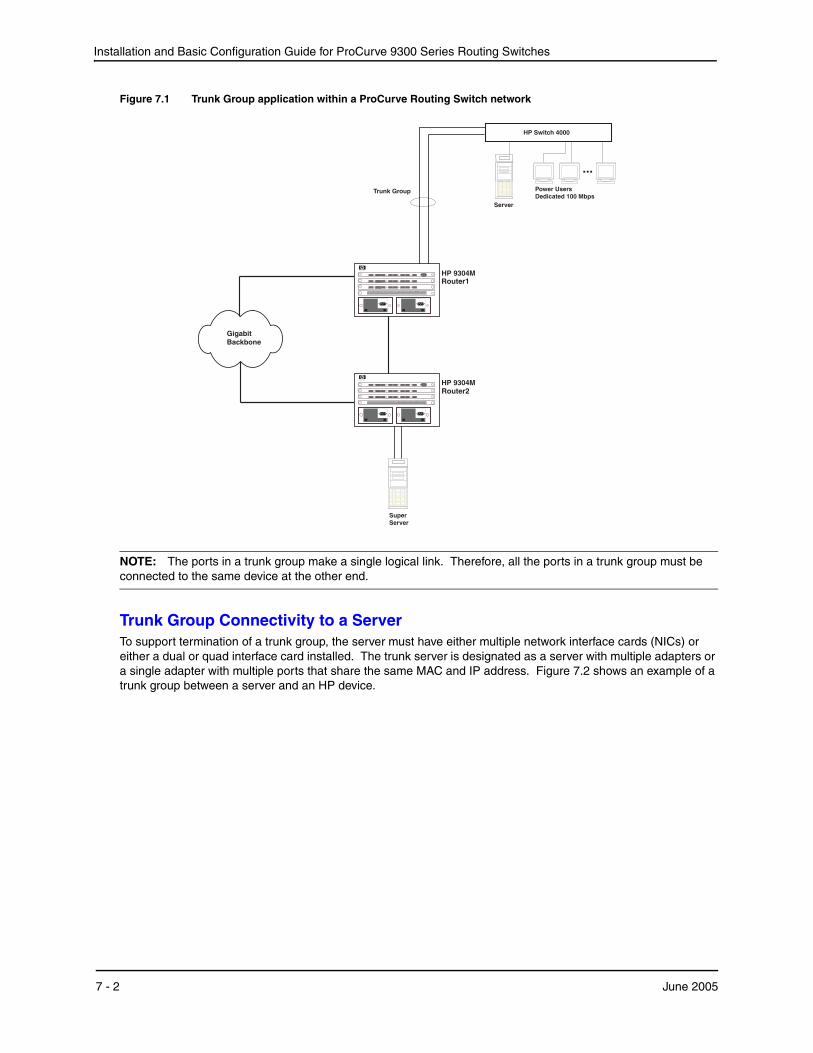
Installation and Basic Configuration Guide for ProCurve 9300 Series Routing Switches
Figure 7.1 Trunk Group application within a ProCurve Routing Switch network
GigabitBackbone
HP 9304M
SuperServer
HP 9304M
Server
...
Power UsersDedicated 100 Mbps
HP Switch 4000
Trunk Group
Router1
Router2
NOTE: The ports in a trunk group make a single logical link. Therefore, all the ports in a trunk group must be connected to the same device at the other end.
Trunk Group Connectivity to a ServerTo support termination of a trunk group, the server must have either multiple network interface cards (NICs) or either a dual or quad interface card installed. The trunk server is designated as a server with multiple adapters or a single adapter with multiple ports that share the same MAC and IP address. Figure 7.2 shows an example of a trunk group between a server and an HP device.
7 - 2 June 2005
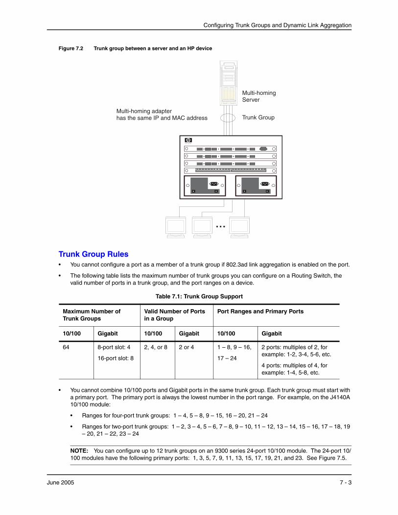
Configuring Trunk Groups and Dynamic Link Aggregation
Figure 7.2 Trunk group between a server and an HP device
......
Multi-homing adapterhas the same IP and MAC address
Multi-homingServer
Trunk Group
Trunk Group Rules• You cannot configure a port as a member of a trunk group if 802.3ad link aggregation is enabled on the port.
• The following table lists the maximum number of trunk groups you can configure on a Routing Switch, the valid number of ports in a trunk group, and the port ranges on a device.
Table 7.1: Trunk Group Support
Maximum Number of Trunk Groups
Valid Number of Ports in a Group
Port Ranges and Primary Ports
10/100 Gigabit 10/100 Gigabit 10/100 Gigabit
64 8-port slot: 4
16-port slot: 8
2, 4, or 8 2 or 4 1 – 8, 9 – 16,
17 – 24
2 ports: multiples of 2, for example: 1-2, 3-4, 5-6, etc.
4 ports: multiples of 4, for example: 1-4, 5-8, etc.
• You cannot combine 10/100 ports and Gigabit ports in the same trunk group. Each trunk group must start with a primary port. The primary port is always the lowest number in the port range. For example, on the J4140A 10/100 module:
• Ranges for four-port trunk groups: 1 – 4, 5 – 8, 9 – 15, 16 – 20, 21 – 24
• Ranges for two-port trunk groups: 1 – 2, 3 – 4, 5 – 6, 7 – 8, 9 – 10, 11 – 12, 13 – 14, 15 – 16, 17 – 18, 19 – 20, 21 – 22, 23 – 24
NOTE: You can configure up to 12 trunk groups on an 9300 series 24-port 10/100 module. The 24-port 10/100 modules have the following primary ports: 1, 3, 5, 7, 9, 11, 13, 15, 17, 19, 21, and 23. See Figure 7.5.
June 2005 7 - 3
Installation and Basic Configuration Guide for ProCurve 9300 Series Routing Switches
• Port assignment on a module must be contiguous. The port range on the module cannot contain gaps. For example, you can configure ports 1, 2, 3, and 4 on a module together as a trunk group but not ports 1, 3, and 4 (excluding 2).
• Port assignment cannot be across multiple trunk group boundaries.All the ports must be connected to the same device at the other end.
• All trunk group member properties must match the lead port of the trunk group with respect to the following parameters:
• Port tag type (untagged or tagged port)
• Port speed and duplex
• QoS priority
To change port parameters, you must change them on the primary port. The software automatically applies the changes to the other ports in the trunk group.
• Make sure the device on the other end of the trunk link can support the same number of ports in the link.
• You can trunk two 10 Gigabit Ethernet ports together. The first port must be in an odd-numbered chassis slot and the second port must be in the following even-numbered slot. Trunking of 10-Gigabit Ethernet ports requires software release 07.6.01b or later. See “Configuring a Trunk Group of 10-Gigabit Ethernet Ports” on page 7-14.
Figure 7.3 shows an example of a valid 2-port trunk group link between devices. The trunk groups in this example are switch trunk groups, between two HP devices. Ports in a valid 2-port trunk group on one device are connected to two ports in a valid 2-port trunk group on another device. The same rules apply to 4-port trunk groups.
7 - 4 June 2005
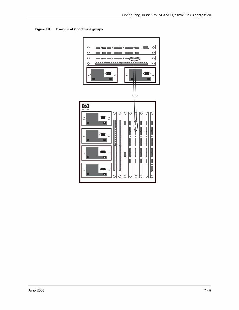
Configuring Trunk Groups and Dynamic Link Aggregation
Figure 7.3 Example of 2-port trunk groups
June 2005 7 - 5
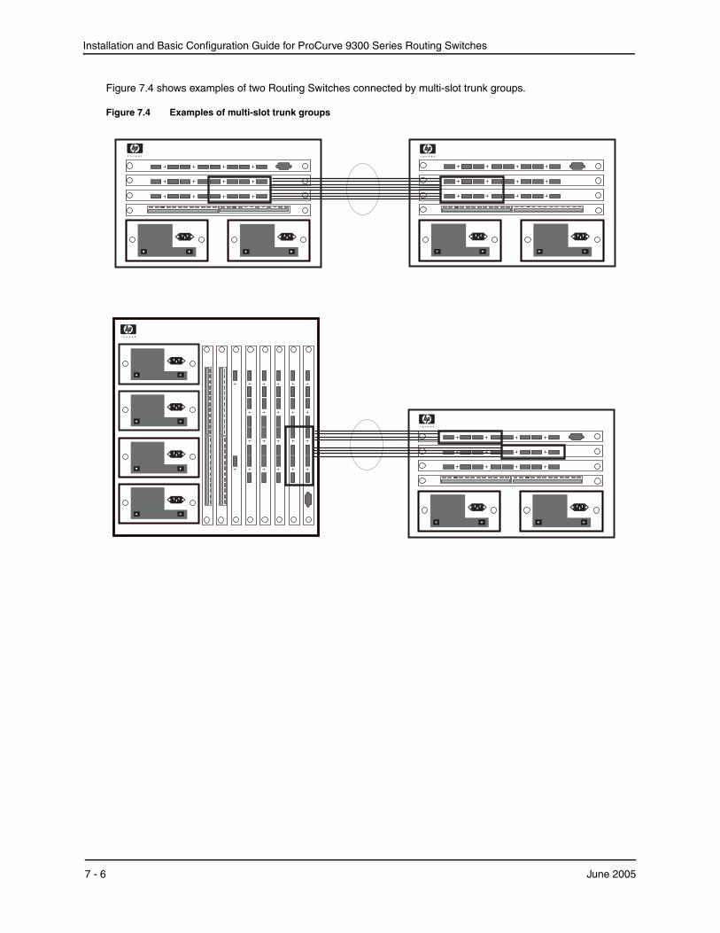
Installation and Basic Configuration Guide for ProCurve 9300 Series Routing Switches
Figure 7.4 shows examples of two Routing Switches connected by multi-slot trunk groups.
Figure 7.4 Examples of multi-slot trunk groups
7 - 6 June 2005
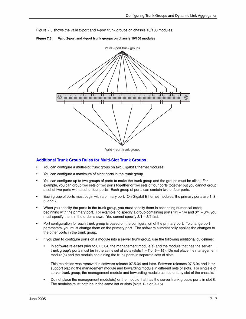
Configuring Trunk Groups and Dynamic Link Aggregation
Figure 7.5 shows the valid 2-port and 4-port trunk groups on chassis 10/100 modules.
Figure 7.5 Valid 2-port and 4-port trunk groups on chassis 10/100 modules
Valid 2-port trunk groups
1 2 3 4 5 6 7 8 9 10 11 12 13 14 15 16 17 18 19 20 21 22 23 24
Valid 4-port trunk groups
Additional Trunk Group Rules for Multi-Slot Trunk Groups
• You can configure a multi-slot trunk group on two Gigabit Ethernet modules.
• You can configure a maximum of eight ports in the trunk group.
• You can configure up to two groups of ports to make the trunk group and the groups must be alike. For example, you can group two sets of two ports together or two sets of four ports together but you cannot group a set of two ports with a set of four ports. Each group of ports can contain two or four ports.
• Each group of ports must begin with a primary port. On Gigabit Ethernet modules, the primary ports are 1, 3, 5, and 7.
• When you specify the ports in the trunk group, you must specify them in ascending numerical order, beginning with the primary port. For example, to specify a group containing ports 1/1 – 1/4 and 3/1 – 3/4, you must specify them in the order shown. You cannot specify 3/1 – 3/4 first.
• Port configuration for each trunk group is based on the configuration of the primary port. To change port parameters, you must change them on the primary port. The software automatically applies the changes to the other ports in the trunk group.
• If you plan to configure ports on a module into a server trunk group, use the following additional guidelines:
• In software releases prior to 07.5.04, the management module(s) and the module that has the server trunk group’s ports must be in the same set of slots (slots 1 – 7 or 9 – 15). Do not place the management module(s) and the module containing the trunk ports in separate sets of slots. This restriction was removed in software release 07.5.04 and later. Software releases 07.5.04 and later support placing the management module and forwarding module in different sets of slots. For single-slot server trunk group, the management module and forwarding module can be on any slot of the chassis.
• Do not place the management module(s) or the module that has the server trunk group’s ports in slot 8. The modules must both be in the same set or slots (slots 1–7 or 9–15).
June 2005 7 - 7

Installation and Basic Configuration Guide for ProCurve 9300 Series Routing Switches
These guidelines apply to a server trunk group that is configured on a single module or on a pair of modules (multi-slot trunk group). You do not need to follow these guidelines for a switch trunk group.
Trunk Group Load SharingWhen you configure a trunk group, you specify whether the trunk group is a “switch” trunk group or a “server” trunk group:
• Switch trunk group – Use this type of trunk group to connect one ProCurve Routing Switch to another ProCurve Routing Switch.
• Server trunk group – Use this type of trunk group to connect a ProCurve Routing Switch to a file server or single host device.
The HP device load shares across the ports in the trunk group. The method used for the load sharing depends on the following:
• Traffic type – Layer 2 or Layer 3
• Trunk type – Switch or server
• For certain traffic, port type on which the traffic enters the HP device (Gigabit or 10/100)
NOTE: The port type applies only to Layer 2 traffic on a server trunk group configured on a Routing Switch.
NOTE: On a device managed by a T-Flow, you can optimize server trunk load sharing on individual ports. See “Enabling Optimized Server Trunk Load Balancing (T-Flow only)” on page 7-19.
NOTE: Starting in software release 07.7.00, EP devices load balance IP traffic on server trunks based on source and destination TCP and UDP application ports (Layer 4 information), as well as on source and destination IP addresses (Layer 3 information). In addition, software release 07.7.00 enables you to configure server trunk load balancing per packet and to specify the maximum number of hash buckets per server trunk. See “Server Trunk Group Load Sharing Enhancements and Options (Release 07.7.00 and Higher)” on page 7-17.
For switch trunk groups, load sharing occurs as follows:
• For switched traffic, load sharing is based on the destination MAC address
• For routed traffic, load sharing is based on the destination IP address
To select a port, the device determines the port in the trunk group that has the fewest number of flows. Traffic for the destination address is sent over the selected port.
For server trunk groups, which connect a ProCurve Routing Switch to a file server or single host device, load sharing occurs as follows:
• For switched traffic, load sharing is based on source MAC address
• For routed traffic, load sharing is based on the combination of source and destination IP addresses
To select a port, the device calculates a hash value derived from source and destination IP addresses, then uses the hash value to select a port from the available ports in the trunk group.
Trunk Load Sharing with EP Modules
Table 7.2 lists how Enhanced Performance devices load balance traffic .
7 - 8 June 2005
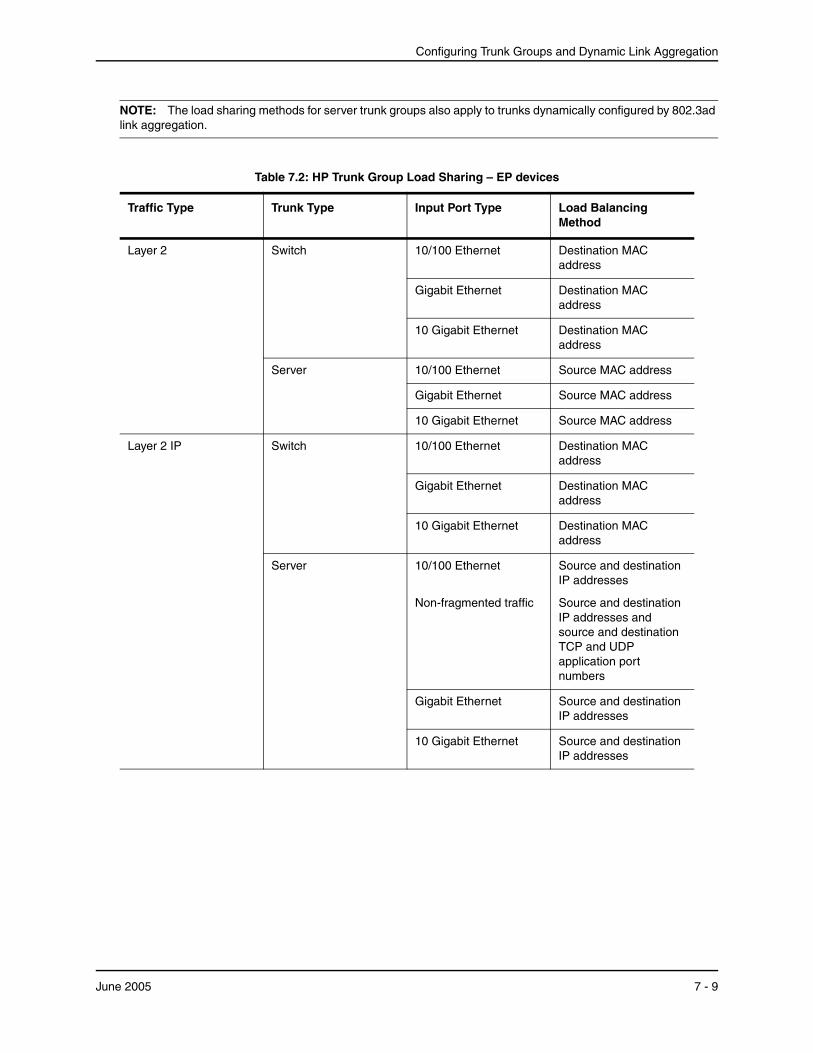
Configuring Trunk Groups and Dynamic Link Aggregation
NOTE: The load sharing methods for server trunk groups also apply to trunks dynamically configured by 802.3ad link aggregation.
Table 7.2: HP Trunk Group Load Sharing – EP devices
Traffic Type Trunk Type Input Port Type Load Balancing Method
Layer 2 Switch 10/100 Ethernet Destination MAC address
Gigabit Ethernet Destination MAC address
10 Gigabit Ethernet Destination MAC address
Server 10/100 Ethernet Source MAC address
Gigabit Ethernet Source MAC address
10 Gigabit Ethernet Source MAC address
Layer 2 IP Switch 10/100 Ethernet Destination MAC address
Gigabit Ethernet Destination MAC address
10 Gigabit Ethernet Destination MAC address
Server 10/100 Ethernet
Non-fragmented traffic
Source and destination IP addresses
Source and destination IP addresses and source and destination TCP and UDP application port numbers
Gigabit Ethernet Source and destination IP addresses
10 Gigabit Ethernet Source and destination IP addresses
June 2005 7 - 9

Installation and Basic Configuration Guide for ProCurve 9300 Series Routing Switches
Trunk Load Sharing with Standard (non-EP) Modules
Table 7.3 lists how Standard (non-EP) Routing Switches load balance traffic .
Table 7.3: HP Trunk Group Load Sharing
Traffic Layer Trunk Group Type Traffic Type Load-Sharing Basis
Layer 3 Switch IP Destination IP address
IPX Destination IPX address
AppleTalk Destination AppleTalk address
All other traffic types Destination MAC address
Server IP Destination IP address
IPX Destination IPX address
AppleTalk Destination AppleTalk address
All other traffic types Destination MAC address
Layer 3 IP Switcha 10/100 Ethernet Destination IP address
Gigabit Ethernet Destination IP address
10 Gigabit Ethernet Destination IP address
Server 10/100 Ethernet
Non-fragmented trafficb
Source and destination IP addresses
Source and destination IP addresses and source and destination TCP and UDP application port
numberb
Gigabit Ethernet Source and destination IP addresses
10 Gigabit Ethernet Source and destination IP addresses
a.By default, Layer 3 IP traffic uses ip load-sharing by-host. Refer to the Command Line Interface Reference for ProCurve 9300/9400 Series Routing Switches for details on this command.b.New in 07.6.01
Table 7.2: HP Trunk Group Load Sharing – EP devices (Continued)
Traffic Type Trunk Type Input Port Type Load Balancing Method
7 - 10 June 2005
Configuring Trunk Groups and Dynamic Link Aggregation
Configuring a Trunk Group1. Disconnect the cables from those ports on both systems that will be connected by the trunk group. Do not
configure the trunk groups with the cables connected.
NOTE: If you connect the cables before configuring the trunk groups and then rebooting, the traffic on the ports can create a spanning tree loop.
2. Configure the trunk group on one of the two Routing Switches involved in the configuration.
3. Save the configuration changes to the startup-config file.
4. Dynamically place the new trunk configuration into effect by entering the trunk deploy command at the global CONFIG level of the CLI.
NOTE: If you are running a software release earlier than 07.5.04, you must reload the software to place a trunk configuration change into effect.
5. If the device at the other end of the trunk group is another Routing Switch, repeat Steps 2 – 4 for the other device.
6. When the trunk groups on both devices are operational, reconnect the cables to those ports that are now configured as trunk groups, starting with the first port (lead port) of each trunk group.
7. To verify the link is operational, use the show trunk command.
Example 1: Configuring the Trunk Groups Shown in Figure 7.1
To configure the trunk groups shown in Figure 7.1, enter the following commands. Notice that the commands are entered on multiple devices.
USING THE CLI
To configure the trunk group link between Router1 and Router2:
NOTE: The text shown in italics in the CLI example below shows messages echoed to the screen in answer to the CLI commands entered.
Router1(config)# trunk switch e 1/5 to 1/8 Trunk 2 is created for next power cycle. Please save configuration to flash and reboot. Router1(config)# write memory Write startup-config in progress. .Write startup-config done. Router1(config)# exit Router1# reload
NOTE: This example uses devices that are not running software release 07.5.004 or later. Devices running software earlier than 07.5.004 must be reloaded in order to place trunk configuration changes into effect. On devices running 07.5.004 or later, you can dynamically place trunk configuration changes into effect by entering the trunk deploy command at the global CONFIG level of the CLI.
To configure the trunk group link between Router2 and the server:
Router2(config)# trunk server e 1/3 to 1/4 Trunk 0 is created for next power cycle. Please save configuration to flash and reboot. Router2(config)# write memory Write startup-config in progress. .Write startup-config done. Router2(config)# exit Router2# reload
June 2005 7 - 11
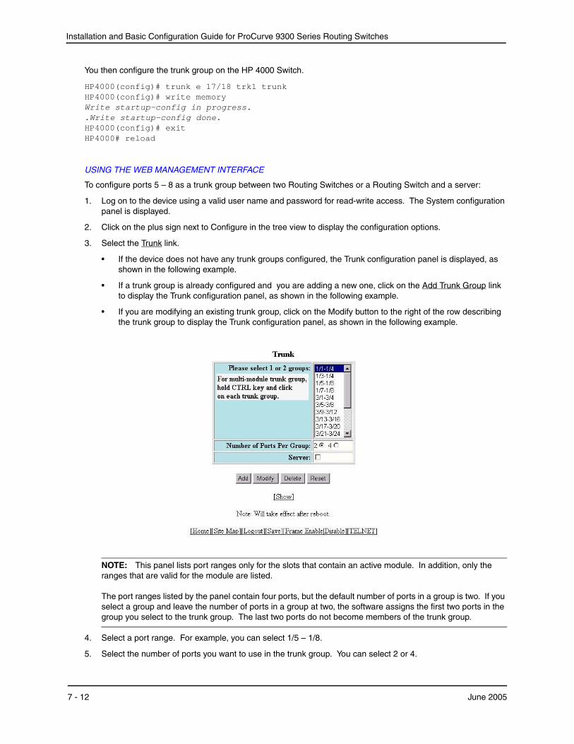
Installation and Basic Configuration Guide for ProCurve 9300 Series Routing Switches
You then configure the trunk group on the HP 4000 Switch.
HP4000(config)# trunk e 17/18 trk1 trunk HP4000(config)# write memory Write startup-config in progress. .Write startup-config done. HP4000(config)# exit HP4000# reload
USING THE WEB MANAGEMENT INTERFACE
To configure ports 5 – 8 as a trunk group between two Routing Switches or a Routing Switch and a server:
1. Log on to the device using a valid user name and password for read-write access. The System configuration panel is displayed.
2. Click on the plus sign next to Configure in the tree view to display the configuration options.
3. Select the Trunk link.
• If the device does not have any trunk groups configured, the Trunk configuration panel is displayed, as shown in the following example.
• If a trunk group is already configured and you are adding a new one, click on the Add Trunk Group link to display the Trunk configuration panel, as shown in the following example.
• If you are modifying an existing trunk group, click on the Modify button to the right of the row describing the trunk group to display the Trunk configuration panel, as shown in the following example.
NOTE: This panel lists port ranges only for the slots that contain an active module. In addition, only the ranges that are valid for the module are listed. The port ranges listed by the panel contain four ports, but the default number of ports in a group is two. If you select a group and leave the number of ports in a group at two, the software assigns the first two ports in the group you select to the trunk group. The last two ports do not become members of the trunk group.
4. Select a port range. For example, you can select 1/5 – 1/8.
5. Select the number of ports you want to use in the trunk group. You can select 2 or 4.
7 - 12 June 2005

Configuring Trunk Groups and Dynamic Link Aggregation
6. Click in the checkbox next to Server to place a checkmark in the box if the other end of the trunk group is a server. If the other end of the connection is a ProCurve Routing Switch, do not click this checkbox.
7. Click Apply to save the changes to the device’s running-config file.
8. Select the Save link at the bottom of the dialog. Select Yes when prompted to save the configuration change to the startup-config file on the device’s flash memory.
9. Click on the plus sign next to Command in the tree view to list the command options.
10. Select the Reload link and select Yes when the Web management interface asks you whether you really want to reload the software.
11. 4If the other end of the trunk group is a Routing Switch, log in to the other device and follow the steps above.
Example 2: Configuring a Trunk Group That Spans Multiple Gigabit Ethernet Modules in a Routing Switch
To configure a trunk group that spans two modules in a 9300 series Routing Switch, use one of the following methods.
USING THE CLI
To configure a trunk group consisting of two groups of ports, 1/1 – 1/4 on module 1 and 4/5 – 4/8 on module 4, enter the following commands:
ProCurveRS(config)# trunk ethernet 1/1 to 1/4 ethernet 4/5 to 4/8 ProCurveRS(config-trunk-1/1-4/8)# write memory ProCurveRS(config-trunk-1/1-4/8)# exit ProCurveRS(config)# trunk deploy
NOTE: The trunk deploy command dynamically places trunk configuration changes into effect, without a software reload. This command is supported only in software release 07.5.04 and later. If you are running a release earlier than 07.5.04, you must reload the software to place trunk configuration changes into effect.
CLI Syntax
Syntax: [no] trunk [server | switch] ethernet <primary-portnum> to <portnum> ethernet <primary-portnum> to <portnum>
Syntax: trunk deploy
The server | switch parameter specifies whether the trunk ports will be connected to a server or to another Routing Switch. This parameter affects the type of load balancing performed by the HP device. See “Trunk Group Load Sharing” on page 7-8. The default is switch.
Each ethernet parameter introduces a port group.
The <primary-portnum> to <portnum> parameters specify a port group. Notice that each port group must begin with a primary port. After you enter this command, the primary port of the first port group specified (which must be the group with the lower port numbers) becomes the primary port for the entire trunk group. For Gigabit Ethernet modules, the primary ports are 1, 3, 5, and 7.
To configure a trunk group consisting of two groups of two ports each, enter commands such as the following:
ProCurveRS(config)# trunk ethernet 1/1 to 1/2 ethernet 3/3 to 3/4 ProCurveRS(config)# write memory ProCurveRS(config)# trunk deploy
Notice that the groups of ports meet the criteria for a multi-slot trunk group. Each group contains the same number of ports (two) and begins on a primary port (1/1 and 3/3).
USING THE WEB MANAGEMENT INTERFACE
1. Log on to the device using a valid user name and password for read-write access. The System configuration panel is displayed.
2. Click on the plus sign next to Configure in the tree view to display the configuration options.
June 2005 7 - 13
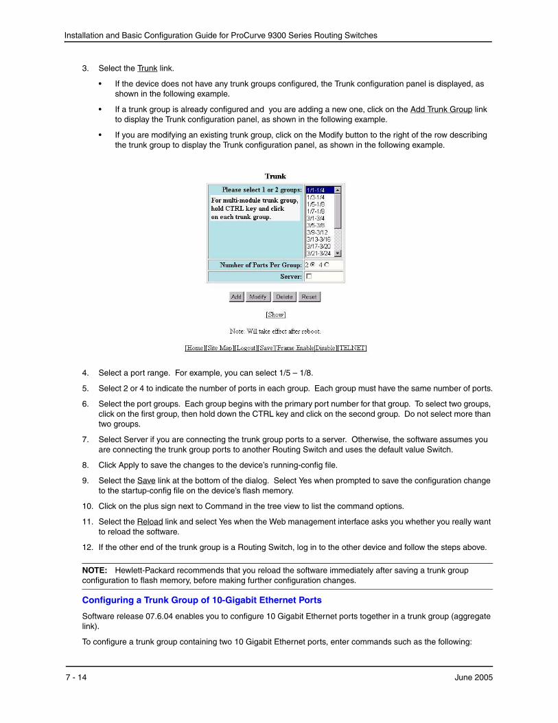
Installation and Basic Configuration Guide for ProCurve 9300 Series Routing Switches
3. Select the Trunk link.
• If the device does not have any trunk groups configured, the Trunk configuration panel is displayed, as shown in the following example.
• If a trunk group is already configured and you are adding a new one, click on the Add Trunk Group link to display the Trunk configuration panel, as shown in the following example.
• If you are modifying an existing trunk group, click on the Modify button to the right of the row describing the trunk group to display the Trunk configuration panel, as shown in the following example.
4. Select a port range. For example, you can select 1/5 – 1/8.
5. Select 2 or 4 to indicate the number of ports in each group. Each group must have the same number of ports.
6. Select the port groups. Each group begins with the primary port number for that group. To select two groups, click on the first group, then hold down the CTRL key and click on the second group. Do not select more than two groups.
7. Select Server if you are connecting the trunk group ports to a server. Otherwise, the software assumes you are connecting the trunk group ports to another Routing Switch and uses the default value Switch.
8. Click Apply to save the changes to the device’s running-config file.
9. Select the Save link at the bottom of the dialog. Select Yes when prompted to save the configuration change to the startup-config file on the device’s flash memory.
10. Click on the plus sign next to Command in the tree view to list the command options.
11. Select the Reload link and select Yes when the Web management interface asks you whether you really want to reload the software.
12. If the other end of the trunk group is a Routing Switch, log in to the other device and follow the steps above.
NOTE: Hewlett-Packard recommends that you reload the software immediately after saving a trunk group configuration to flash memory, before making further configuration changes.
Configuring a Trunk Group of 10-Gigabit Ethernet Ports
Software release 07.6.04 enables you to configure 10 Gigabit Ethernet ports together in a trunk group (aggregate link).
To configure a trunk group containing two 10 Gigabit Ethernet ports, enter commands such as the following:
7 - 14 June 2005
Configuring Trunk Groups and Dynamic Link Aggregation
ProCurveRS(config)# trunk ethernet 1/1 to 2/1 ProCurveRS(config-trunk-1/1-2/1)# write memory ProCurveRS(config-trunk-1/1-2/1)# exit ProCurveRS(config)# trunk deploy
These commands configure a trunk group consisting of 10 Gigabit Ethernet ports 1/1 and 2/1, then deploy the trunk group. The trunk configuration does not take effect until you deploy it.
Syntax: [no] trunk [server | switch] ethernet <primary-portnum> to <secondary-portnum>
Syntax: trunk deploy
The server | switch parameter specifies whether the trunk ports will be connected to a server or to another Routing Switch. This parameter affects the type of load balancing performed by the HP device. See “Trunk Group Load Sharing” on page 7-8. The default is switch.
The <primary-portnum> parameter specifies the trunk group’s primary port. You must specify an odd-numbered slot. See the table “Trunk Group Support” on page 7-3 for valid primary ports.
The <secondary-portnum> parameter specifies the secondary port in the trunk group. You must specify a port that is in the next slot number up from the primary port. For example, if the primary port is 1/1, specify 2/1 as the secondary port.
NOTE: Two-port trunk groups are supported for 10 Gigabit Ethernet. You cannot specify more than two ports.
To display configuration information and load-sharing statistics for the trunk group, enter the show trunk command. See “Displaying Trunk Group Configuration Information” on page 7-22.
Additional Trunking OptionsThe CLI contains commands for doing the following:
• Naming a trunk port
• Disabling or re-enabling a trunk port
• Deleting a trunk group
NOTE: To monitor the traffic on a trunk port, see “Monitoring an Individual Trunk Port” on page 6-52.
Naming a Trunk Port
To name an individual port in a trunk group, enter a command such as the following at the trunk group configuration level:
ProCurveRS(config-trunk-4/1-4/4)# port-name customer1 ethernet 4/2
Syntax: [no] port-name <text> ethernet <portnum>
The <text> parameter specifies the port name. The name can be up to 50 characters long.
This command assigns the name “customer1” to port 4/2 in the trunk group consisting of ports 4/1 – 4/4.
Disabling or Re-Enabling a Trunk Port
You can disable or re-enable individual ports in a trunk group. To disable an individual port in a trunk group, enter commands such as the following at the trunk group configuration level:
ProCurveRS(config-trunk-4/1-4/4)# config-trunk-ind ProCurveRS(config-trunk-4/1-4/4)# disable ethernet 4/2
Syntax: [no] config-trunk-ind
Syntax: [no] disable ethernet <portnum>
The config-trunk-ind command enables configuration of individual ports in the trunk group. If you do not use this command, the disable command will be valid only for the primary port in the trunk group and will disable all ports
June 2005 7 - 15

Installation and Basic Configuration Guide for ProCurve 9300 Series Routing Switches
in the trunk group. You need to enter the config-trunk-ind command only once in a trunk group. After you enter the command, all applicable port configuration commands apply to individual ports only.
NOTE: If you enter no config-trunk-ind, all port configuration commands are removed from the individual ports and the configuration of the primary port is applied to all the ports. Also, once you enter the no config-trunk-ind command, the enable, disable, and monitor commands are valid only on the primary port and apply to the entire trunk group.
The disable command disables the port. The states of other ports in the trunk group are not affected.
If you have configured a name for the trunk port, you can specify the port name, as shown in the following example:
ProCurveRS(config-trunk-4/1-4/4)# config-trunk-ind ProCurveRS(config-trunk-4/1-4/4)# disable customer1
Syntax: disable <portname>
To enable an individual port in a trunk group, enter commands such as the following at the trunk group configuration level:
ProCurveRS(config-trunk-4/1-4/4)# config-trunk-ind ProCurveRS(config-trunk-4/1-4/4)# enable ethernet 4/2
Syntax: enable ethernet <portnum>
Syntax: enable <portname>
Disabling or Re-Enabling a Range or List of Trunk PortsTo disable a range of ports in a trunk group, enter commands such as the following:
ProCurveRS(config)# trunk switch ethernet 2/1 to 2/8 ProCurveRS(config-trunk-2/1-2/8)# config-trunk-ind ProCurveRS(config-trunk-2/1-2/8)# disable ethernet 2/2 to 2/5
This command disables ports 2/2 – 2/5 in trunk group 2/1 – 2/8.
To disable a list of ports, enter a command such as the following:
ProCurveRS(config-trunk-2/1-2/8)# disable ethernet 2/2 ethernet 2/4 ethernet 2/7
This command disables ports 2/2, 2/4, and 2/7 in the trunk group.
You can specify a range and a list on the same command line. For example, to re-enable some trunk ports, enter a command such as the following:
ProCurveRS(config-trunk-2/1-2/8)# enable ethernet 2/2 to 2/5 ethernet 2/7
Syntax: [no] disable ethernet <portnum> [to <portnum> | ethernet <portnum>]
Syntax: [no] enable ethernet <portnum> [to <portnum> | ethernet <portnum>]
The to <portnum> parameter indicates that you are specifying a range. Specify the lower port number in the range first, then to, then the higher port number in the range.
The ethernet <portnum> parameter specifies an individual port. You can enter this parameter multiple times to specify a list, as shown in the examples above.
Deleting a Trunk Group
To delete a trunk group, use either of the following methods.
USING THE CLI
To delete a trunk group, use “no” in front of the command you used to create the trunk group. For example, to remove one of the trunk groups configured in the examples above, enter the following command:
ProCurveRS(config)# no trunk ethernet 1/1 to 1/2 ethernet 3/3 to 3/4
Syntax: no trunk ethernet <portnum> to <portnum>
7 - 16 June 2005

Configuring Trunk Groups and Dynamic Link Aggregation
USING THE WEB MANAGEMENT INTERFACE
To delete a trunk group:
1. Disconnect the ports to the server or Routing Switch at the other end of the trunk.
2. Log on to the device using a valid user name and password for read-write access. The System configuration panel is displayed.
3. Click on the plus sign next to Configure in the tree view to display the configuration options.
4. Select the Trunk link to display a table listing the configured trunk groups.
5. Click the Delete button next to the trunk group you want to delete.
6. Select the Save link at the bottom of the dialog. Select Yes when prompted to save the configuration change to the startup-config file on the device’s flash memory.
7. Click on the plus sign next to Command in the tree view to list the command options.
8. Select the Reload link and select Yes when the Web management interface asks you whether you really want to reload the software.
NOTE: If the other end of the trunk group is a Routing Switch, log in to the other system and follow the applicable steps above.
Server Trunk Group Load Sharing Enhancements and Options (Release 07.7.00 and Higher)Software release 07.7.00 introduced the following server trunk load balancing enhancements and options on HP’s EP devices:
• Load balancing IP traffic based on TCP and UDP application ports
• Ability to configure load balancing per packet
• Ability to configure the maximum number of hash buckets per server trunk
These new features improve the overall performance of server trunk load balancing for Layer 2 and Layer 3 IP traffic.
NOTE: These enhancements apply to server trunks only.
NOTE: These enhancements apply to IP traffic only.
Server Trunk Load Balancing Based on Application Ports
In software release 07.7.00 and later, HP’s EP devices load balance IP traffic on server trunks based on source and destination TCP and UDP application ports (Layer 4 information), as well as on source and destination IP addresses (Layer 3 information). Previous releases supported server trunk load balancing based on Layer 3 information only. Adding Layer 4 information to the load balancing scheme enables the HP device to efficiently forward traffic to server trunk group ports.
You do not need to perform any configuration steps to enable this support. If you configure the device for server trunking, it automatically load balances traffic over server trunks based on Layer 3 and Layer 4 information.
For information about configuring server trunks, see the "Configuring Trunk Groups and Dynamic Link Aggregation" chapter in the Advanced Configuration and Management Guide for ProCurve 9300/9400 Series Routing Switches.
Note Regarding Fragmented PacketsThe descriptions above apply to non-fragmented packets. For fragmented packets, the HP device uses the source and destination IP addresses only, so that all fragments in a session are forwarded over the same port.
June 2005 7 - 17
Installation and Basic Configuration Guide for ProCurve 9300 Series Routing Switches
Configuring Server Trunk Load Balancing Per Packet
NOTE: The configuration commands in this section apply to incoming (trunk) ports only.
Starting in release 07.7.00, you can configure the ports on an HP device to load balance IP traffic based on individual packets received on the interface. When you enable this feature, the device uses the IP packet headers to load balance the traffic among all the ports in the trunk group.
You configure this feature at the Interface level of the CLI, and not globally (on the entire device). When you configure this feature on the primary port of the trunk group, the software automatically applies it to the other ports in the trunk group.
To enable this feature, enter commands such as the following:
ProCurveRS(config)# interface e 1/1 ProCurveRS(config-if-e10000-1/1)# serv-trunk-per-pkt-lb
When interface e 1 receives IP packets destined for a trunk port, it uses information in the IP packet header to select the trunk port on which to forward the traffic.
Syntax: [no] serv-trunk-per-pkt-lb
Configuring the Maximum Number of Hash Buckets for Server Trunks
NOTE: This section applies to ProCurve Routing Switches only.
Server trunks use hash buckets to implement packet forwarding and load balancing. The hash buckets enable forwarding of packets in hardware, as opposed to forwarding them in software (sending them to the CPU). Packets forwarded in hardware travel faster in comparison to packets sent to the CPU for processing.
When the HP device learns that a specific packet has to go through an outgoing port, it places an entry in the hash bucket. The entry defines the data path from the incoming port to the outgoing port. When the device receives subsequent packets destined for the same path, it retrieves the entry in the hash bucket and forwards the packets accordingly.
In releases prior to 07.7.00, the HP device allocates a fixed number of hash buckets for each server trunk. This number is not configurable.
In software release 07.7.00, depending on the number of server trunks configured on the HP device, you can specify the maximum number of hash buckets per server trunk, up to a maximum of 256. In addition, the total number of hash buckets for all server trunks combined has increased. The 9315M supports a total of 1024 hash buckets, and the 9304M and 9308M support a total of 8192 hash buckets.
Increasing the number of hash buckets per server trunk enhances the speed and efficiency at which the HP device forwards and load balances IP packets on server trunk ports.
Table 7.4 shows the hash bucket configurations supported on the 9315M.
Table 7.4: Configurable Hash Buckets on the 9315M
Maximum Number of Hash Buckets per Server Trunk
Number of Server Trunks Total Number of Hash Buckets for all Server Trunks Combined
16 – default value 15 240
32 15 480
64 15 960
128 8 1024
256 4 1024
7 - 18 June 2005
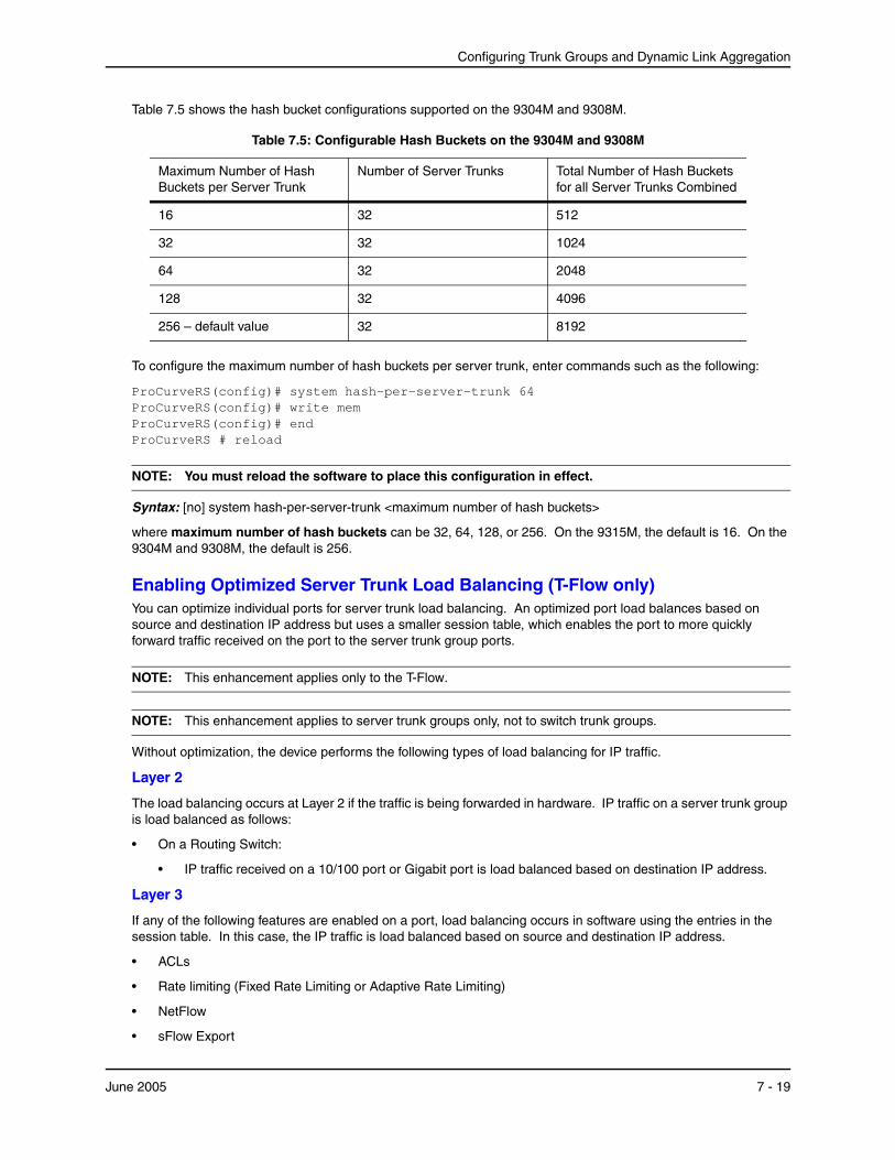
Configuring Trunk Groups and Dynamic Link Aggregation
Table 7.5 shows the hash bucket configurations supported on the 9304M and 9308M.
Table 7.5: Configurable Hash Buckets on the 9304M and 9308M
Maximum Number of Hash Buckets per Server Trunk
Number of Server Trunks Total Number of Hash Buckets for all Server Trunks Combined
16 32 512
32 32 1024
64 32 2048
128 32 4096
256 – default value 32 8192
To configure the maximum number of hash buckets per server trunk, enter commands such as the following:
ProCurveRS(config)# system hash-per-server-trunk 64 ProCurveRS(config)# write mem ProCurveRS(config)# end ProCurveRS # reload
NOTE: You must reload the software to place this configuration in effect.
Syntax: [no] system hash-per-server-trunk <maximum number of hash buckets>
where maximum number of hash buckets can be 32, 64, 128, or 256. On the 9315M, the default is 16. On the 9304M and 9308M, the default is 256.
Enabling Optimized Server Trunk Load Balancing (T-Flow only)You can optimize individual ports for server trunk load balancing. An optimized port load balances based on source and destination IP address but uses a smaller session table, which enables the port to more quickly forward traffic received on the port to the server trunk group ports.
NOTE: This enhancement applies only to the T-Flow.
NOTE: This enhancement applies to server trunk groups only, not to switch trunk groups.
Without optimization, the device performs the following types of load balancing for IP traffic.
Layer 2
The load balancing occurs at Layer 2 if the traffic is being forwarded in hardware. IP traffic on a server trunk group is load balanced as follows:
• On a Routing Switch:
• IP traffic received on a 10/100 port or Gigabit port is load balanced based on destination IP address.
Layer 3
If any of the following features are enabled on a port, load balancing occurs in software using the entries in the session table. In this case, the IP traffic is load balanced based on source and destination IP address.
• ACLs
• Rate limiting (Fixed Rate Limiting or Adaptive Rate Limiting)
• NetFlow
• sFlow Export
June 2005 7 - 19
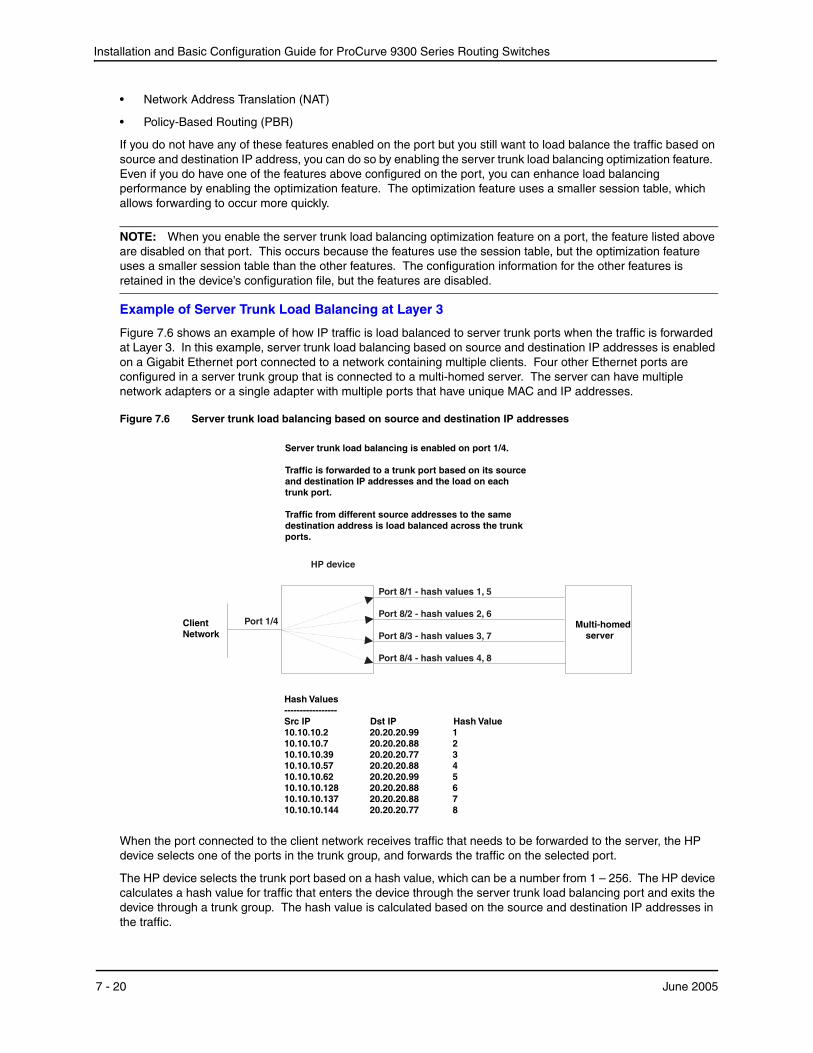
Installation and Basic Configuration Guide for ProCurve 9300 Series Routing Switches
• Network Address Translation (NAT)
• Policy-Based Routing (PBR)
If you do not have any of these features enabled on the port but you still want to load balance the traffic based on source and destination IP address, you can do so by enabling the server trunk load balancing optimization feature. Even if you do have one of the features above configured on the port, you can enhance load balancing performance by enabling the optimization feature. The optimization feature uses a smaller session table, which allows forwarding to occur more quickly.
NOTE: When you enable the server trunk load balancing optimization feature on a port, the feature listed above are disabled on that port. This occurs because the features use the session table, but the optimization feature uses a smaller session table than the other features. The configuration information for the other features is retained in the device’s configuration file, but the features are disabled.
Example of Server Trunk Load Balancing at Layer 3
Figure 7.6 shows an example of how IP traffic is load balanced to server trunk ports when the traffic is forwarded at Layer 3. In this example, server trunk load balancing based on source and destination IP addresses is enabled on a Gigabit Ethernet port connected to a network containing multiple clients. Four other Ethernet ports are configured in a server trunk group that is connected to a multi-homed server. The server can have multiple network adapters or a single adapter with multiple ports that have unique MAC and IP addresses.
Figure 7.6 Server trunk load balancing based on source and destination IP addresses
When the port connected to the client network receives traffic that needs to be forwarded to the server, the HP device selects one of the ports in the trunk group, and forwards the traffic on the selected port.
The HP device selects the trunk port based on a hash value, which can be a number from 1 – 256. The HP device calculates a hash value for traffic that enters the device through the server trunk load balancing port and exits the device through a trunk group. The hash value is calculated based on the source and destination IP addresses in the traffic.
7 - 20 June 2005
Configuring Trunk Groups and Dynamic Link Aggregation
After the HP device calculates the hash value for the traffic, the device examines the trunk ports connected to the destination address and selects the port with the fewest hash values already assigned. After calculating a hash value and assigning the value to a port, the device always uses the same port to forward traffic for the same source and destination IP addresses.
For example, the first time the HP device receives traffic from 10.10.10.7 addressed to 20.20.20.88, the device calculates the hash value 2 for the traffic. The device then checks the trunk ports to see whether a port is assigned to hash value 2.
• If a trunk port is assigned to hash value 2, the device uses that port to forward the traffic.
• Otherwise, the device assigns hash value 2 to the trunk port with the fewest hash values already assigned to it. The device continues to use this port for traffic with hash value 2, until a state change occurs on a trunk port or a trunk port is added or removed.
Trunk ports keep the hash values that are assigned to them until a trunk port’s state changes or a trunk port is added or removed. When any of these changes occurs, the HP device clears the hash values from all of the trunk ports and begins calculating and assigning hash values again for new traffic.
Configuration Considerations
• You can enable the server trunk load balancing optimization feature on an individual port basis only. You cannot enable the feature on a virtual routing interface basis. This is true even if you have assigned a virtual routing interface to the trunk ports.
• Each TSP CPU has a separate hash bucket for the ports managed by the CPU. The buckets are independent of one another. Thus, if you enable the feature on more than one port and the ports are not managed by the same CPU, it is possible for the same hash values to be assigned to more than one trunk port, because the values are assigned separately by each CPU.
• When you enable the server trunk load balancing optimization feature on a port, the following features are disabled on the port:
• ACLs
• Rate limiting (Fixed Rate Limiting or Adaptive Rate Limiting)
• NetFlow
• sFlow Export
• Network Address Translation (NAT)
• Policy-Based Routing (PBR)
The features are disabled because the server trunk load balancing optimization feature uses a simpler session table whose forwarding entries are keyed by source and destination IP addresses only. The features listed above require use of the standard session table, which also includes keys for the IP protocol and the source and destination TCP or UDP application ports (when the IP protocol is TCP or UDP).
The configuration information for these features remains in the device’s configuration file but the features are disabled on the port.
Enabling Server Trunk Load Balancing Optimization (T-Flow ModuleOnly)
To enable server trunk load balancing optimization, you enable the feature on the ports that will receive the traffic that needs to be load balanced. To enable the optimization feature on a port, enter the following command at the configuration level for the port:
ProCurveRS(config-if-e1000-1/4)# stlb
Syntax: [no] stlb
Displaying Server Trunk Load Balancing Information
To display the current hash assignments for server trunk ports, log on to the TSP CPU that is managing the ports, then enter the show trunk command. Here is an example.
June 2005 7 - 21

Installation and Basic Configuration Guide for ProCurve 9300 Series Routing Switches
ProCurveRS# rconsole 2 1 ProCurveRS2/1 # show trunk ProCurveRS2/1 #Number of trunk groups: 1 Note: Value in () is for server trunk hashing. TRUNK ID: 71 server:1 multi-slot:0 configured ports: 8/1 8/2 8/3 8/4 active ports : 8/1 (2) 8/2 (2) 8/3 (2) 8/4 (1) ProCurveRS2/1 # rconsole-exit
The rconsole 2 1 command logs on to TSP CPU 1 on the T-Flow module in slot 2.
The show trunk command displays the trunk information for the ports managed by the CPU. The server trunk load balancing information is shown in bold type in this example. The number in parentheses indicates how many hash values are assigned to the port. The CPU assigns the hash values evenly to the trunk ports managed by the CPU. In this example, the next time the device needs to assign a hash value, the device will assign the value to port 8/4.
The rconsole-exit command logs out of the TSP CPU.
Syntax: show trunk
For information about the T-Flow, including how the module distributes management of the ports in the chassis, see “Using the T-Flow Redundant Management Module” on page 4-1.
Displaying Trunk Group Configuration InformationTo display configuration information for the trunk groups configured on the Routing Switch, use one of the following methods. Each method displays information for configured trunk groups and operational trunk groups. A configured trunk group is one that has been configured in the software but has not been placed into operation by a reset or reboot. An operational trunk group is one that has been placed into operation by a reset or reboot.
USING THE CLI
Enter the following command at any CLI level:
ProCurveRS(config)# show trunk Configured trunks: Trunk Type Ports 1 Switch 1/1 1/2 1/3 1/4 2/1 2/2 2/3 2/4 Operational trunks: Trunk Type Ports Duplex Speed Tag Priority 1 Switch 1/1 1/2 1/3 1/4 2/1 2/2 2/3 2/4 None None No level0
Syntax: show trunk [ethernet <portnum> to <portnum>]
The following table describes the information displayed by the show trunk command.
Table 7.6: CLI Trunk Group Information
This Field... Displays...
Trunk The trunk group number. The software numbers the groups in the display to make the display easy to use.
Type The type of trunk group, which can be one of the following:
• Server – The trunk group is connected to a server.
• Switch – The trunk group is connected to another Routing Switch.
7 - 22 June 2005
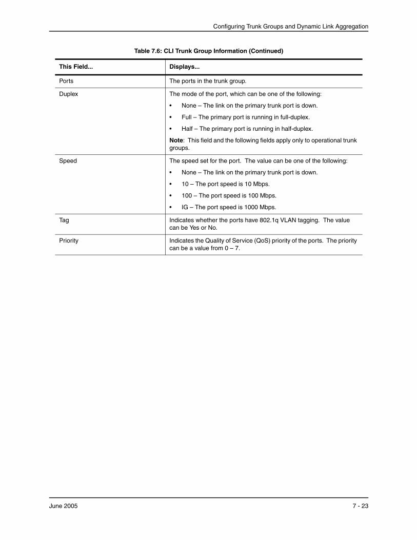
Configuring Trunk Groups and Dynamic Link Aggregation
Ports The ports in the trunk group.
Duplex The mode of the port, which can be one of the following:
• None – The link on the primary trunk port is down.
• Full – The primary port is running in full-duplex.
• Half – The primary port is running in half-duplex.
Note: This field and the following fields apply only to operational trunk groups.
Speed The speed set for the port. The value can be one of the following:
• None – The link on the primary trunk port is down.
• 10 – The port speed is 10 Mbps.
• 100 – The port speed is 100 Mbps.
• IG – The port speed is 1000 Mbps.
Tag Indicates whether the ports have 802.1q VLAN tagging. The value can be Yes or No.
Priority Indicates the Quality of Service (QoS) priority of the ports. The priority can be a value from 0 – 7.
Table 7.6: CLI Trunk Group Information (Continued)
This Field... Displays...
June 2005 7 - 23
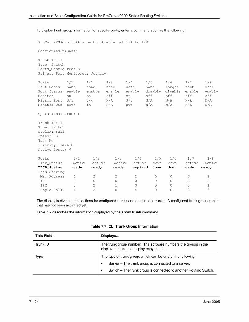
Installation and Basic Configuration Guide for ProCurve 9300 Series Routing Switches
To display trunk group information for specific ports, enter a command such as the following:
ProCurveRS(config)# show trunk ethernet 1/1 to 1/8 Configured trunks: Trunk ID: 1 Type: Switch Ports_Configured: 8 Primary Port Monitored: Jointly Ports 1/1 1/2 1/3 1/4 1/5 1/6 1/7 1/8 Port Names none none none none none longna test none Port_Status enable enable enable enable disable disable enable enable Monitor on on off on off off off off Mirror Port 3/3 3/4 N/A 3/5 N/A N/A N/A N/A Monitor Dir both in N/A out N/A N/A N/A N/A Operational trunks: Trunk ID: 1 Type: Switch Duplex: Full Speed: 1G Tag: No Priority: level0 Active Ports: 6 Ports 1/1 1/2 1/3 1/4 1/5 1/6 1/7 1/8 Link_Status active active active active down down active active LACP_Status ready ready ready expired down down ready ready Load Sharing Mac Address 3 2 2 2 0 0 6 1 IP 0 0 0 0 0 0 0 0 IPX 0 2 1 0 0 0 0 1 Apple Talk 1 2 0 4 0 0 0 3
The display is divided into sections for configured trunks and operational trunks. A configured trunk group is one that has not been activated yet.
Table 7.7 describes the information displayed by the show trunk command.
Table 7.7: CLI Trunk Group Information
This Field... Displays...
Trunk ID The trunk group number. The software numbers the groups in the display to make the display easy to use.
Type The type of trunk group, which can be one of the following:
• Server – The trunk group is connected to a server.
• Switch – The trunk group is connected to another Routing Switch.
7 - 24 June 2005
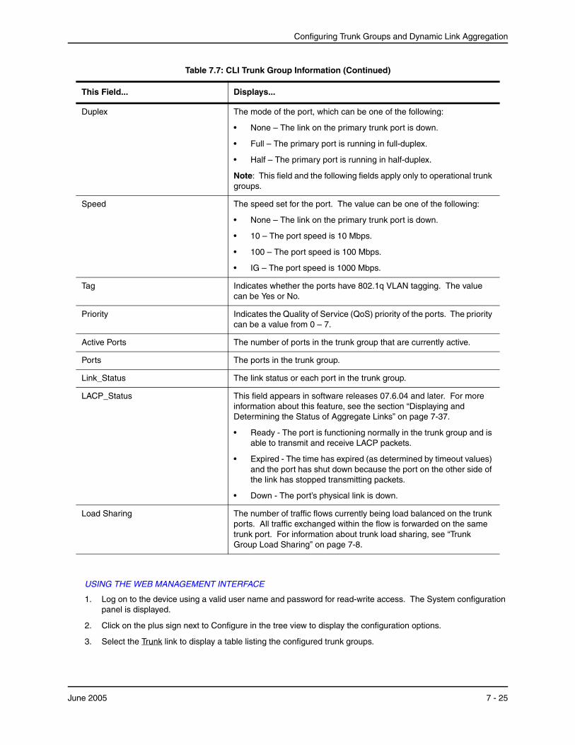
Configuring Trunk Groups and Dynamic Link Aggregation
USING THE WEB MANAGEMENT INTERFACE
1. Log on to the device using a valid user name and password for read-write access. The System configuration panel is displayed.
2. Click on the plus sign next to Configure in the tree view to display the configuration options.
3. Select the Trunk link to display a table listing the configured trunk groups.
Duplex The mode of the port, which can be one of the following:
• None – The link on the primary trunk port is down.
• Full – The primary port is running in full-duplex.
• Half – The primary port is running in half-duplex.
Note: This field and the following fields apply only to operational trunk groups.
Speed The speed set for the port. The value can be one of the following:
• None – The link on the primary trunk port is down.
• 10 – The port speed is 10 Mbps.
• 100 – The port speed is 100 Mbps.
• IG – The port speed is 1000 Mbps.
Tag Indicates whether the ports have 802.1q VLAN tagging. The value can be Yes or No.
Priority Indicates the Quality of Service (QoS) priority of the ports. The priority can be a value from 0 – 7.
Active Ports The number of ports in the trunk group that are currently active.
Ports The ports in the trunk group.
Link_Status The link status or each port in the trunk group.
LACP_Status This field appears in software releases 07.6.04 and later. For more information about this feature, see the section “Displaying and Determining the Status of Aggregate Links” on page 7-37.
• Ready - The port is functioning normally in the trunk group and is able to transmit and receive LACP packets.
• Expired - The time has expired (as determined by timeout values) and the port has shut down because the port on the other side of the link has stopped transmitting packets.
• Down - The port’s physical link is down.
Load Sharing The number of traffic flows currently being load balanced on the trunk ports. All traffic exchanged within the flow is forwarded on the same trunk port. For information about trunk load sharing, see “Trunk Group Load Sharing” on page 7-8.
Table 7.7: CLI Trunk Group Information (Continued)
This Field... Displays...
June 2005 7 - 25

Installation and Basic Configuration Guide for ProCurve 9300 Series Routing Switches
This display shows the following information.
Table 7.8: Web Management Trunk Group Information
This Field... Displays...
Connection Type The type of trunk group, which can be one of the following:
• Server – The trunk group is connected to a server.
• Switch – The trunk group is connected to another Routing Switch.
Port Members The ports in the trunk group.
7 - 26 June 2005
Configuring Trunk Groups and Dynamic Link Aggregation
Dynamic Link AggregationThe software supports the IEEE 802.3ad standard for link aggregation. This standard describes the Link Aggregation Control Protocol (LACP), a mechanism for allowing ports on both sides of a redundant link to configure themselves into a trunk link (aggregate link), without the need for manual configuration of the ports into trunk groups.
When you enable link aggregation on a group of HP ports, the HP ports can negotiate with the ports at the remote ends of the links to establish trunk groups.
Usage Notes• You cannot use 802.3ad link aggregation on a port configured as a member of a static trunk group.
• This feature is supported only for 10/100 and Gigabit Ethernet ports.
• When the feature dynamically adds or changes a trunk group, the show trunk command displays the trunk as both configured and active. However, the show running-config or write terminal command does not contain a trunk command defining the new or changed trunk group.
• If the feature places a port into a trunk group as a secondary port, all configuration information except information related to link aggregation is removed from the port. For example, if port 1/3 has an IP interface, and the link aggregation feature places port 1/3 into a trunk group consisting of ports 1/1 – 1/4, the IP interface is removed from the port.
• If you use this feature on a Routing Switch that is running OSPF or BGP4, the feature causes these protocols to reset when a dynamic link change occurs. The reset includes ending and restarting neighbor sessions with OSPF and BGP4 peers, and clearing and relearning dynamic route entries and forwarding cache entries. Although the reset causes a brief interruption, the protocols automatically resume normal operation.
• You can enable link aggregation on 802.1q tagged ports (ports that belong to more than one port-based VLAN) in software release 07.7.00 and later.
• Dynamic Operation of Allocation Keys (section 43.6.2 in the 802.3ad specification) is supported in release 07.7.00 and later.
Configuration RulesHP ports follow the same configuration rules for dynamically created aggregate links as they do for statically configured trunk groups. See “Trunk Group Rules” on page 7-3 and “Trunk Group Load Sharing” on page 7-8.
Figure 7.7 on page 7-28 shows some examples of valid aggregate links.
June 2005 7 - 27
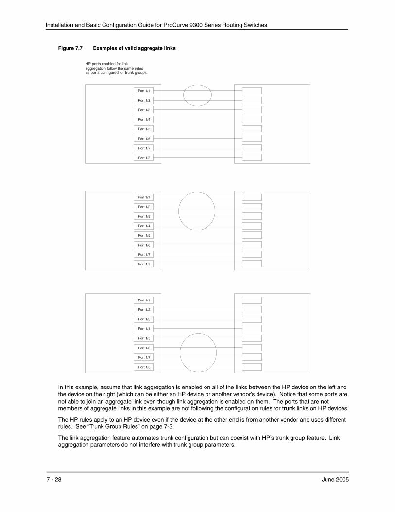
Installation and Basic Configuration Guide for ProCurve 9300 Series Routing Switches
Figure 7.7 Examples of valid aggregate links
Port 1/2
Port 1/4
Port 1/1
Port 1/6
Port 1/3
Port 1/7
Port 1/8
Port 1/5
Port 1/2
Port 1/4
Port 1/1
Port 1/6
Port 1/3
Port 1/7
Port 1/8
Port 1/5
HP ports enabled for linkaggregation follow the same rulesas ports configured for trunk groups.
Port 1/4
Port 1/1
Port 1/6
Port 1/3
Port 1/7
Port 1/8
Port 1/5
Port 1/2
In this example, assume that link aggregation is enabled on all of the links between the HP device on the left and the device on the right (which can be either an HP device or another vendor’s device). Notice that some ports are not able to join an aggregate link even though link aggregation is enabled on them. The ports that are not members of aggregate links in this example are not following the configuration rules for trunk links on HP devices.
The HP rules apply to an HP device even if the device at the other end is from another vendor and uses different rules. See “Trunk Group Rules” on page 7-3.
The link aggregation feature automates trunk configuration but can coexist with HP’s trunk group feature. Link aggregation parameters do not interfere with trunk group parameters.
7 - 28 June 2005
Configuring Trunk Groups and Dynamic Link Aggregation
NOTE: Use the link aggregation feature only if the device at the other end of the links you want to aggregate also supports IEEE 802.3ad link aggregation. Otherwise, you need to manually configure the trunk links.
Link aggregation support is disabled by default. You can enable the feature on an individual port basis, in active or passive mode.
• Active mode – When you enable a port for active link aggregation, the HP port can exchange standard LACP Protocol Data Unit (LACPDU) messages to negotiate trunk group configuration with the port on the other side of the link. In addition, the HP port actively sends LACPDU messages on the link to search for a link aggregation partner at the other end of the link, and can initiate an LACPDU exchange to negotiate link aggregation parameters with an appropriately configured remote port.
• Passive mode – When you enable a port for passive link aggregation, the HP port can exchange LACPDU messages with the port at the remote end of the link, but the HP port cannot search for a link aggregation port or initiate negotiation of an aggregate link. Thus, the port at the remote end of the link must initiate the LACPDU exchange.
NOTE: HP recommends that you disable or remove the cables from the ports you plan to enable for dynamic link aggregation. Doing so prevents the possibility that LACP will use a partial configuration to talk to the other side of a link. A partial configuration does not cause errors, but does sometimes require LACP to be disabled and re-enabled on both sides of the link to ensure that a full configuration is used. It's easier to disable a port or remove its cable first. This applies both for active link aggregation and passive link aggregation.
802.3ad Enhancements in Release 07.6.04Software release 07.6.04 contains the following enhancements to 802.3ad support:
• Adaptation to trunk disappearance. The HP device will tear down an aggregate link if the device at the other end of the link reboots or brings all the links down. Tearing the aggregate link down prevents a mismatch if the other device has a different trunk configuration following the reboot or re-establishment of the links.
• The criteria for being eligible to be in an aggregate link are more flexible. A range of ports can contain down ports and still be eligible to become an aggregate link.
Adaptation to Trunk Disappearance
Release 07.6.04 prevents trunk mismatches caused when one device changes the number of ports in group of ports that has become part of an 802.3 aggregate link. In 07.6.04 and later, if a device changes the number of ports in an active aggregate link, the HP device on the other end of the link tears down the link. Once the other device recovers, 802.3 can renegotiate the link without a mismatch.
In previous releases, it is possible for a trunk mismatch to occur between two devices that have established an aggregate link. This can occur if one of the devices reboots or brings the trunk links down, then re-establishes the links but with a different number of trunk ports. Figure 7.8 shows an example.
June 2005 7 - 29
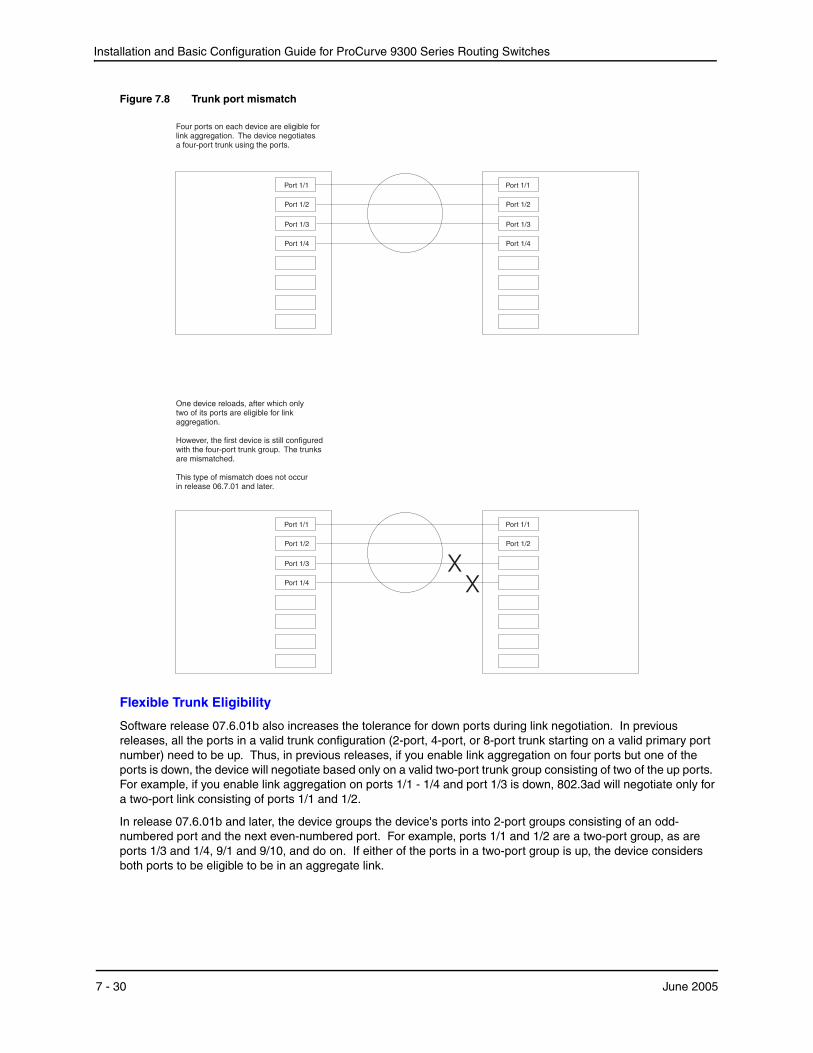
Installation and Basic Configuration Guide for ProCurve 9300 Series Routing Switches
Figure 7.8 Trunk port mismatch
One device reloads, after which onlytwo of its ports are eligible for linkaggregation.
However, the first device is still configuredwith the four-port trunk group. The trunksare mismatched.
This type of mismatch does not occurin release 06.7.01 and later.
Port 1/1
Port 1/2
Port 1/4
Port 1/1
Port 1/3
Port 1/2
Four ports on each device are eligible forlink aggregation. The device negotiatesa four-port trunk using the ports.
Port 1/4
Port 1/1
Port 1/3
Port 1/2
Port 1/4
Port 1/1
Port 1/3
Port 1/2
XX
Flexible Trunk Eligibility
Software release 07.6.01b also increases the tolerance for down ports during link negotiation. In previous releases, all the ports in a valid trunk configuration (2-port, 4-port, or 8-port trunk starting on a valid primary port number) need to be up. Thus, in previous releases, if you enable link aggregation on four ports but one of the ports is down, the device will negotiate based only on a valid two-port trunk group consisting of two of the up ports. For example, if you enable link aggregation on ports 1/1 - 1/4 and port 1/3 is down, 802.3ad will negotiate only for a two-port link consisting of ports 1/1 and 1/2.
In release 07.6.01b and later, the device groups the device's ports into 2-port groups consisting of an odd-numbered port and the next even-numbered port. For example, ports 1/1 and 1/2 are a two-port group, as are ports 1/3 and 1/4, 9/1 and 9/10, and do on. If either of the ports in a two-port group is up, the device considers both ports to be eligible to be in an aggregate link.
7 - 30 June 2005
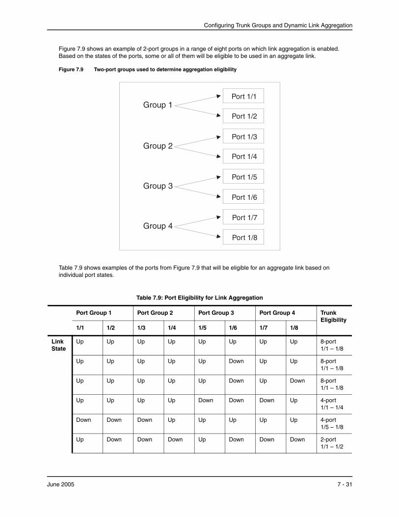
Configuring Trunk Groups and Dynamic Link Aggregation
Figure 7.9 shows an example of 2-port groups in a range of eight ports on which link aggregation is enabled. Based on the states of the ports, some or all of them will be eligible to be used in an aggregate link.
Figure 7.9 Two-port groups used to determine aggregation eligibility
Port 1/2
Port 1/4
Port 1/1
Port 1/6
Port 1/3
Port 1/7
Port 1/8
Port 1/5
Group 2
Group 3
Group 4
Group 1
Table 7.9 shows examples of the ports from Figure 7.9 that will be eligible for an aggregate link based on individual port states.
Table 7.9: Port Eligibility for Link Aggregation
Port Group 1 Port Group 2 Port Group 3 Port Group 4 Trunk Eligibility
1/1 1/2 1/3 1/4 1/5 1/6 1/7 1/8
Link State
Up Up Up Up Up Up Up Up 8-port 1/1 – 1/8
Up Up Up Up Up Down Up Up 8-port 1/1 – 1/8
Up Up Up Up Up Down Up Down 8-port 1/1 – 1/8
Up Up Up Up Down Down Down Up 4-port 1/1 – 1/4
Down Down Down Up Up Up Up Up 4-port 1/5 – 1/8
Up Down Down Down Up Down Down Down 2-port 1/1 – 1/2
June 2005 7 - 31
Installation and Basic Configuration Guide for ProCurve 9300 Series Routing Switches
As shown in these examples, all or a subset of the ports within a port range will be eligible for formation into an aggregate link based on port states. Notice that the sets of ports that are eligible for the aggregate link must be valid static trunk configurations. For example, a 4-port link consisting of ports 1/4 – 1/7 is not valid because this port configuration is not valid for static trunk groups on the HP device.
Enabling Link AggregationBy default, link aggregation is disabled on all ports. To enable the feature, use one of the following CLI methods.
USING THE CLI
To enable link aggregation on a set of ports, enter commands such as the following at the interface configuration level of the CLI.
NOTE: Configuration commands for link aggregation differ depending on whether you are using the default link aggregation key automatically assigned by the software, or if you are assigning a different, unique key. Follow the commands below, according to the type of key you are using. For more information about keys, see “Key” on page 7-33.
Using the Default Key Assigned by the SoftwareProCurveRS(config)# interface ethernet 1/1 ProCurveRS(config-if-e1000-1/1)# link-aggregate active ProCurveRS(config)# interface ethernet 1/2 ProCurveRS(config-if-e1000-1/2)# link-aggregate active
The commands in this example enable the active mode of link aggregation on ports 1/1 and 1/2. The ports can send and receive LACPDU messages. Note that these ports will use the default key, since one has not been explicitly configured.
Assigning a Unique KeyProCurveRS(config)# interface ethernet 1/1 ProCurveRS(config-if-e1000-1/1)# link-aggregate configure key 10000 ProCurveRS(config-if-e1000-1/1)# link-aggregate active ProCurveRS(config)# interface ethernet 1/2 ProCurveRS(config-if-e1000-1/2)# link-aggregate configure key 10000 ProCurveRS(config-if-e1000-1/2)# link-aggregate active
The commands in this example assign the key 10000 and enable the active mode of link aggregation on ports 1/1 and 1/2. The ports can send and receive LACPDU messages.
NOTE: As shown in this example, when configuring a key, it is pertinent that you assign the key prior to enabling link aggregation.
The following commands enable passive link aggregation on ports 1/5 – 1/8:
ProCurveRS(config)# interface ethernet 1/5 to 1/8 ProCurveRS(config-mif-1/5-1/8)# link-aggregate passive
The commands in this example enable the passive mode of link aggregation on ports 1/5 – 1/8. These ports wait for the other end of the link to contact them. After this occurs, the ports can send and receive LACPDU messages.
To disable link aggregation on a port, enter a command such as the following:
ProCurveRS(config-if-e1000-1/8)# link-aggregate off
Syntax: [no] link-aggregate active | passive | off
Syntax: [no] link-aggregate configure [system-priority <num>] | [port-priority <num>] | [key <num>] | [type server | switch]
7 - 32 June 2005

Configuring Trunk Groups and Dynamic Link Aggregation
NOTE: For more information about keys, including details about the syntax shown above, see “Key” on page 7-33.
Link Aggregation ParametersYou can change the settings for the following link aggregation parameters, on an individual port basis:
• System priority
• Port priority
• Link type
• Key
System Priority
The system priority specifies the HP device’s link aggregation priority relative to the devices at the other ends of the links on which link aggregation is enabled. A higher value indicates a lower priority. You can specify a priority from 0 – 65535. The default is 1.
NOTE: If you are connecting the HP device to another vendor’s device and the link aggregation feature is not working, set the system priority on the HP device to a lower priority (a higher priority value). In some cases, this change allows the link aggregation feature to operate successfully between the two devices.
Link Type
The link type specifies whether the trunk is connecting to a server (server link) or to another networking device (switch link). The default link type is switch.
Key
Every port that is 802.3ad-enabled has a key. The key identifies the group of potential trunk ports to which the port belongs. Ports with the same key are called a key group and are eligible to be in the same trunk group.
When you enable link-aggregation on a tagged or untagged port, HP’s software assigns a default key to the port. The default key is based on the position of the port within an eight-port group (the maximum number of ports in a trunk group on a Routing Switch). The software assigns the keys in ascending numerical order, beginning with key 0 for the first group of eight ports. For example, a 24-port module in chassis slot 1 contains keys 0, 1, and 2 by default. Ports 1/1 – 1/8 have key 0, ports 1/9 – 1/16 have key 1, and so on.
All ports within an aggregate link must have the same key. However, if the device has ports that are connected to two different devices, and the port groups allow the ports to form into separate aggregate links with the two devices, then each group of ports can have the same key while belonging to separate aggregate links with different devices. Figure 7.10 on page 7-34 shows an example.
June 2005 7 - 33
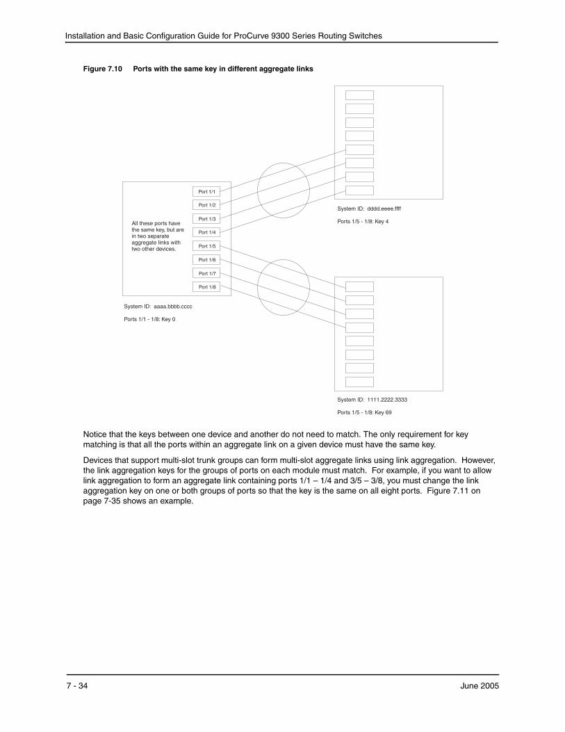
Installation and Basic Configuration Guide for ProCurve 9300 Series Routing Switches
Figure 7.10 Ports with the same key in different aggregate links
Port 1/2
Port 1/4
Port 1/1
Port 1/6
Port 1/3
Port 1/7
Port 1/8
Port 1/5
System ID: 1111.2222.3333
Ports 1/5 - 1/8: Key 69
All these ports havethe same key, but arein two separateaggregate links withtwo other devices.
System ID: aaaa.bbbb.cccc
Ports 1/1 - 1/8: Key 0
System ID: dddd.eeee.ffff
Ports 1/5 - 1/8: Key 4
Notice that the keys between one device and another do not need to match. The only requirement for key matching is that all the ports within an aggregate link on a given device must have the same key.
Devices that support multi-slot trunk groups can form multi-slot aggregate links using link aggregation. However, the link aggregation keys for the groups of ports on each module must match. For example, if you want to allow link aggregation to form an aggregate link containing ports 1/1 – 1/4 and 3/5 – 3/8, you must change the link aggregation key on one or both groups of ports so that the key is the same on all eight ports. Figure 7.11 on page 7-35 shows an example.
7 - 34 June 2005
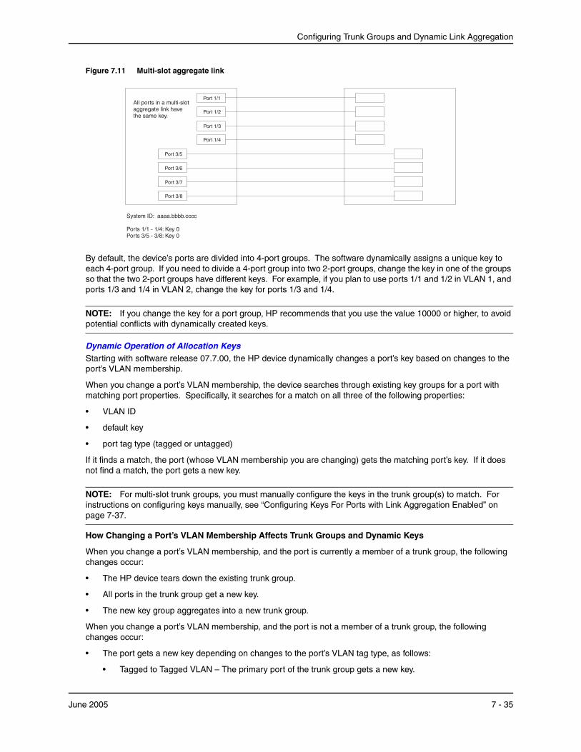
Configuring Trunk Groups and Dynamic Link Aggregation
Figure 7.11 Multi-slot aggregate link
All ports in a multi-slotaggregate link havethe same key.
Port 1/2
Port 1/4
Port 1/1
Port 3/6
Port 1/3
Port 3/7
Port 3/8
Port 3/5
System ID: aaaa.bbbb.cccc
Ports 1/1 - 1/4: Key 0Ports 3/5 - 3/8: Key 0
By default, the device’s ports are divided into 4-port groups. The software dynamically assigns a unique key to each 4-port group. If you need to divide a 4-port group into two 2-port groups, change the key in one of the groups so that the two 2-port groups have different keys. For example, if you plan to use ports 1/1 and 1/2 in VLAN 1, and ports 1/3 and 1/4 in VLAN 2, change the key for ports 1/3 and 1/4.
NOTE: If you change the key for a port group, HP recommends that you use the value 10000 or higher, to avoid potential conflicts with dynamically created keys.
Dynamic Operation of Allocation KeysStarting with software release 07.7.00, the HP device dynamically changes a port’s key based on changes to the port’s VLAN membership.
When you change a port’s VLAN membership, the device searches through existing key groups for a port with matching port properties. Specifically, it searches for a match on all three of the following properties:
• VLAN ID
• default key
• port tag type (tagged or untagged)
If it finds a match, the port (whose VLAN membership you are changing) gets the matching port’s key. If it does not find a match, the port gets a new key.
NOTE: For multi-slot trunk groups, you must manually configure the keys in the trunk group(s) to match. For instructions on configuring keys manually, see “Configuring Keys For Ports with Link Aggregation Enabled” on page 7-37.
How Changing a Port’s VLAN Membership Affects Trunk Groups and Dynamic Keys
When you change a port’s VLAN membership, and the port is currently a member of a trunk group, the following changes occur:
• The HP device tears down the existing trunk group.
• All ports in the trunk group get a new key.
• The new key group aggregates into a new trunk group.
When you change a port’s VLAN membership, and the port is not a member of a trunk group, the following changes occur:
• The port gets a new key depending on changes to the port’s VLAN tag type, as follows:
• Tagged to Tagged VLAN – The primary port of the trunk group gets a new key.
June 2005 7 - 35
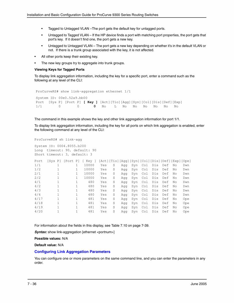
Installation and Basic Configuration Guide for ProCurve 9300 Series Routing Switches
• Tagged to Untagged VLAN –The port gets the default key for untagged ports.
• Untagged to Tagged VLAN – If the HP device finds a port with matching port properties, the port gets that port’s key. If it doesn’t find one, the port gets a new key.
• Untagged to Untagged VLAN – The port gets a new key depending on whether it’s in the default VLAN or not. If there is a trunk group associated with the key, it is not affected.
• All other ports keep their existing key.
• The new key groups try to aggregate into trunk groups.
Viewing Keys for Tagged Ports
To display link aggregation information, including the key for a specific port, enter a command such as the following at any level of the CLI:
ProCurveRS# show link-aggregation ethernet 1/1
System ID: 00e0.52a9.bb00 Port [Sys P] [Port P] [ Key ] [Act][Tio][Agg][Syn][Col][Dis][Def][Exp] 1/1 0 0 0 No L No No No No No No
The command in this example shows the key and other link aggregation information for port 1/1.
To display link aggregation information, including the key for all ports on which link aggregation is enabled, enter the following command at any level of the CLI:
ProCurveRS# sh link-agg
System ID: 0004.8055.b200 Long timeout: 90, default: 90 Short timeout: 3, default: 3
Port [Sys P] [Port P] [ Key ] [Act][Tio][Agg][Syn][Col][Dis][Def][Exp][Ope] 1/1 1 1 10000 Yes S Agg Syn Col Dis Def No Dwn 1/2 1 1 10000 Yes S Agg Syn Col Dis Def No Dwn 2/1 1 1 10000 Yes S Agg Syn Col Dis Def No Dwn 2/2 1 1 10000 Yes S Agg Syn Col Dis Def No Dwn 4/1 1 1 480 Yes S Agg Syn Col Dis Def No Dwn 4/2 1 1 480 Yes S Agg Syn Col Dis Def No Dwn 4/3 1 1 480 Yes S Agg Syn Col Dis Def No Dwn 4/4 1 1 480 Yes S Agg Syn Col Dis Def No Dwn 4/17 1 1 481 Yes S Agg Syn Col Dis Def No Ope 4/18 1 1 481 Yes S Agg Syn Col Dis Def No Ope 4/19 1 1 481 Yes S Agg Syn Col Dis Def No Ope 4/20 1 1 481 Yes S Agg Syn Col Dis Def No Ope
For information about the fields in this display, see Table 7.10 on page 7-39.
Syntax: show link-aggregation [ethernet <portnum>]
Possible values: N/A
Default value: N/A
Configuring Link Aggregation Parameters
You can configure one or more parameters on the same command line, and you can enter the parameters in any order.
7 - 36 June 2005

Configuring Trunk Groups and Dynamic Link Aggregation
NOTE: For key configuration only, configuration commands differ depending on whether or not link aggregation is enabled on the port(s). Follow the appropriate set of commands below, according to your system’s configuration.
For example, to change a port group’s key from the one assigned by the software to another value, enter commands such as the following:
NOTE: Use this command sequence to change the key for ports that do not have link aggregation enabled, and for all other link aggregation parameters (i.e., system priority, port priority, and link type).
ProCurveRS(config)# interface ethernet 1/1 to 1/4 ProCurveRS(config-mif-1/1-1/4)# link-aggregate configure key 10000 ProCurveRS(config-mif-1/1-1/4)# interface ethernet 3/5 to 3/8 ProCurveRS(config-mif-3/5-3/8)# link-aggregate configure key 10000
Configuring Keys For Ports with Link Aggregation Enabled
NOTE: As shown in this command sequence, to change the key on ports that already have link aggregation enabled, you must first turn OFF link aggregation, configure the new key, then re-enable link aggregation.
ProCurveRS(config)# interface ethernet 1/1 to 1/4 ProCurveRS(config-mif-1/1-1/4)# link-aggregate off ProCurveRS(config-mif-1/1-1/4)# link-aggregate configure key 10000 ProCurveRS(config-mif-1/1-1/4)# link-aggregate active ProCurveRS(config-mif-1/1-1/4)# interface ethernet 3/5 to 3/8 ProCurveRS(config-mif-3/5-3/8)# link-aggregate off ProCurveRS(config-mif-3/5-3/8)# link-aggregate configure key 10000 ProCurveRS(config-mif-3/5-3/8)# link-aggregate active
These commands change the key for ports 1/1 – 1/4 and 3/5 – 3/8 to 10000. Since all ports in an aggregate link must have the same key, the command in this example enables ports 1/1 – 1/4 and 3/5 – 3/8 to form a multi-slot aggregate link.
Syntax: [no] link-aggregate configure [system-priority <num>] | [port-priority <num>] | [key <num>] | [type server | switch]
The system-priority <num> parameter specifies the HP device’s link aggregation priority. A higher value indicates a lower priority. You can specify a priority from 0 – 65535. The default is 1.
The port-priority <num> parameter specifies an individual port’s priority within the port group. A higher value indicates a lower priority. You can specify a priority from 0 – 65535. The default is 1.
The key <num> parameter identifies the group of ports that are eligible to be aggregated into a trunk group. The software automatically assigns a key to each group of ports. The software assigns the keys in ascending numerical order, beginning with 0. You can change a port group’s key to a value from 0 – 65535.
NOTE: If you change the key for a port group, HP recommends that you use the value 10000 or higher, to avoid potential conflicts with dynamically created keys.
The type server | switch parameter specifies whether the port group is connected to a server (server) or to another networking device (switch). The default is switch.
You can enter one or more of the command’s parameters on the same command line, in any order.
Displaying and Determining the Status of Aggregate LinksSoftware release 07.6.04 and later provides the ability to determine the status of ports that are members of an aggregate link, and whether or not LACPDU messages are being transmitted between the ports. In releases prior to 07.6.04, this level of detail was not readily available. With the link aggregation enhancement, the show link-aggregation command provides the ability to view the status of dynamic links.
June 2005 7 - 37
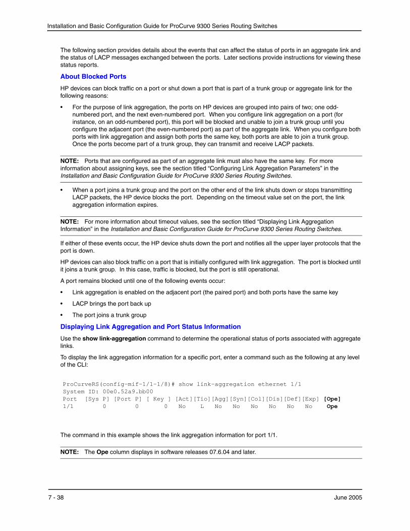
Installation and Basic Configuration Guide for ProCurve 9300 Series Routing Switches
The following section provides details about the events that can affect the status of ports in an aggregate link and the status of LACP messages exchanged between the ports. Later sections provide instructions for viewing these status reports.
About Blocked Ports
HP devices can block traffic on a port or shut down a port that is part of a trunk group or aggregate link for the following reasons:
• For the purpose of link aggregation, the ports on HP devices are grouped into pairs of two; one odd-numbered port, and the next even-numbered port. When you configure link aggregation on a port (for instance, on an odd-numbered port), this port will be blocked and unable to join a trunk group until you configure the adjacent port (the even-numbered port) as part of the aggregate link. When you configure both ports with link aggregation and assign both ports the same key, both ports are able to join a trunk group. Once the ports become part of a trunk group, they can transmit and receive LACP packets.
NOTE: Ports that are configured as part of an aggregate link must also have the same key. For more information about assigning keys, see the section titled “Configuring Link Aggregation Parameters” in the Installation and Basic Configuration Guide for ProCurve 9300 Series Routing Switches.
• When a port joins a trunk group and the port on the other end of the link shuts down or stops transmitting LACP packets, the HP device blocks the port. Depending on the timeout value set on the port, the link aggregation information expires.
NOTE: For more information about timeout values, see the section titled “Displaying Link Aggregation Information” in the Installation and Basic Configuration Guide for ProCurve 9300 Series Routing Switches.
If either of these events occur, the HP device shuts down the port and notifies all the upper layer protocols that the port is down.
HP devices can also block traffic on a port that is initially configured with link aggregation. The port is blocked until it joins a trunk group. In this case, traffic is blocked, but the port is still operational.
A port remains blocked until one of the following events occur:
• Link aggregation is enabled on the adjacent port (the paired port) and both ports have the same key
• LACP brings the port back up
• The port joins a trunk group
Displaying Link Aggregation and Port Status Information
Use the show link-aggregation command to determine the operational status of ports associated with aggregate links.
To display the link aggregation information for a specific port, enter a command such as the following at any level of the CLI:
ProCurveRS(config-mif-1/1-1/8)# show link-aggregation ethernet 1/1 System ID: 00e0.52a9.bb00 Port [Sys P] [Port P] [ Key ] [Act][Tio][Agg][Syn][Col][Dis][Def][Exp] [Ope] 1/1 0 0 0 No L No No No No No No Ope
The command in this example shows the link aggregation information for port 1/1.
NOTE: The Ope column displays in software releases 07.6.04 and later.
7 - 38 June 2005
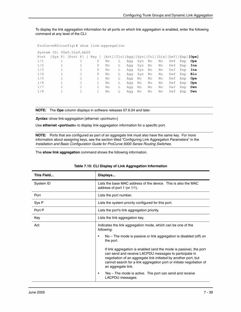
Configuring Trunk Groups and Dynamic Link Aggregation
To display the link aggregation information for all ports on which link aggregation is enabled, enter the following command at any level of the CLI:
ProCurveRS(config)# show link-aggregation
System ID: 00e0.52a9.bb00 Port [Sys P] [Port P] [ Key ] [Act][Tio][Agg][Syn][Col][Dis][Def][Exp][Ope] 1/1 1 1 0 No L Agg Syn No No Def Exp Ope 1/2 1 1 0 No L Agg Syn No No Def Exp Ina 1/3 1 1 0 No L Agg Syn No No Def Exp Ina 1/4 1 1 0 No L Agg Syn No No Def Exp Blo 1/5 1 1 1 No L Agg No No No Def Exp Ope 1/6 1 1 1 No L Agg No No No Def Exp Ope 1/7 1 1 1 No L Agg No No No Def Exp Dwn 1/8 1 1 1 No L Agg No No No Def Exp Dwn
NOTE: The Ope column displays in software releases 07.6.04 and later.
Syntax: show link-aggregation [ethernet <portnum>]
Use ethernet <portnum> to display link-aggregation information for a specific port.
NOTE: Ports that are configured as part of an aggregate link must also have the same key. For more information about assigning keys, see the section titled “Configuring Link Aggregation Parameters” in the Installation and Basic Configuration Guide for ProCurve 9300 Series Routing Switches.
The show link aggregation command shows the following information.
Table 7.10: CLI Display of Link Aggregation Information
This Field... Displays...
System ID Lists the base MAC address of the device. This is also the MAC address of port 1 (or 1/1).
Port Lists the port number.
Sys P Lists the system priority configured for this port.
Port P Lists the port’s link aggregation priority.
Key Lists the link aggregation key.
Act Indicates the link aggregation mode, which can be one of the following:
• No – The mode is passive or link aggregation is disabled (off) on the port. If link aggregation is enabled (and the mode is passive), the port can send and receive LACPDU messages to participate in negotiation of an aggregate link initiated by another port, but cannot search for a link aggregation port or initiate negotiation of an aggregate link.
• Yes – The mode is active. The port can send and receive LACPDU messages.
June 2005 7 - 39
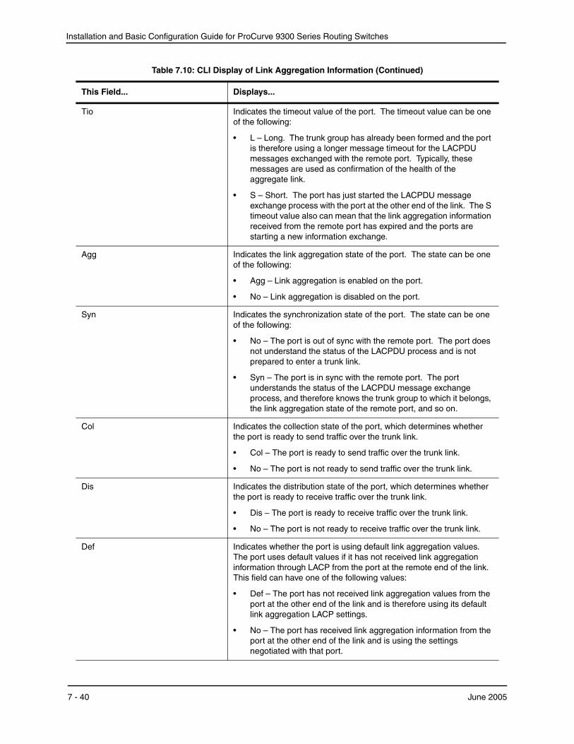
Installation and Basic Configuration Guide for ProCurve 9300 Series Routing Switches
Tio Indicates the timeout value of the port. The timeout value can be one of the following:
• L – Long. The trunk group has already been formed and the port is therefore using a longer message timeout for the LACPDU messages exchanged with the remote port. Typically, these messages are used as confirmation of the health of the aggregate link.
• S – Short. The port has just started the LACPDU message exchange process with the port at the other end of the link. The S timeout value also can mean that the link aggregation information received from the remote port has expired and the ports are starting a new information exchange.
Agg Indicates the link aggregation state of the port. The state can be one of the following:
• Agg – Link aggregation is enabled on the port.
• No – Link aggregation is disabled on the port.
Syn Indicates the synchronization state of the port. The state can be one of the following:
• No – The port is out of sync with the remote port. The port does not understand the status of the LACPDU process and is not prepared to enter a trunk link.
• Syn – The port is in sync with the remote port. The port understands the status of the LACPDU message exchange process, and therefore knows the trunk group to which it belongs, the link aggregation state of the remote port, and so on.
Col Indicates the collection state of the port, which determines whether the port is ready to send traffic over the trunk link.
• Col – The port is ready to send traffic over the trunk link.
• No – The port is not ready to send traffic over the trunk link.
Dis Indicates the distribution state of the port, which determines whether the port is ready to receive traffic over the trunk link.
• Dis – The port is ready to receive traffic over the trunk link.
• No – The port is not ready to receive traffic over the trunk link.
Def Indicates whether the port is using default link aggregation values. The port uses default values if it has not received link aggregation information through LACP from the port at the remote end of the link. This field can have one of the following values:
• Def – The port has not received link aggregation values from the port at the other end of the link and is therefore using its default link aggregation LACP settings.
• No – The port has received link aggregation information from the port at the other end of the link and is using the settings negotiated with that port.
Table 7.10: CLI Display of Link Aggregation Information (Continued)
This Field... Displays...
7 - 40 June 2005
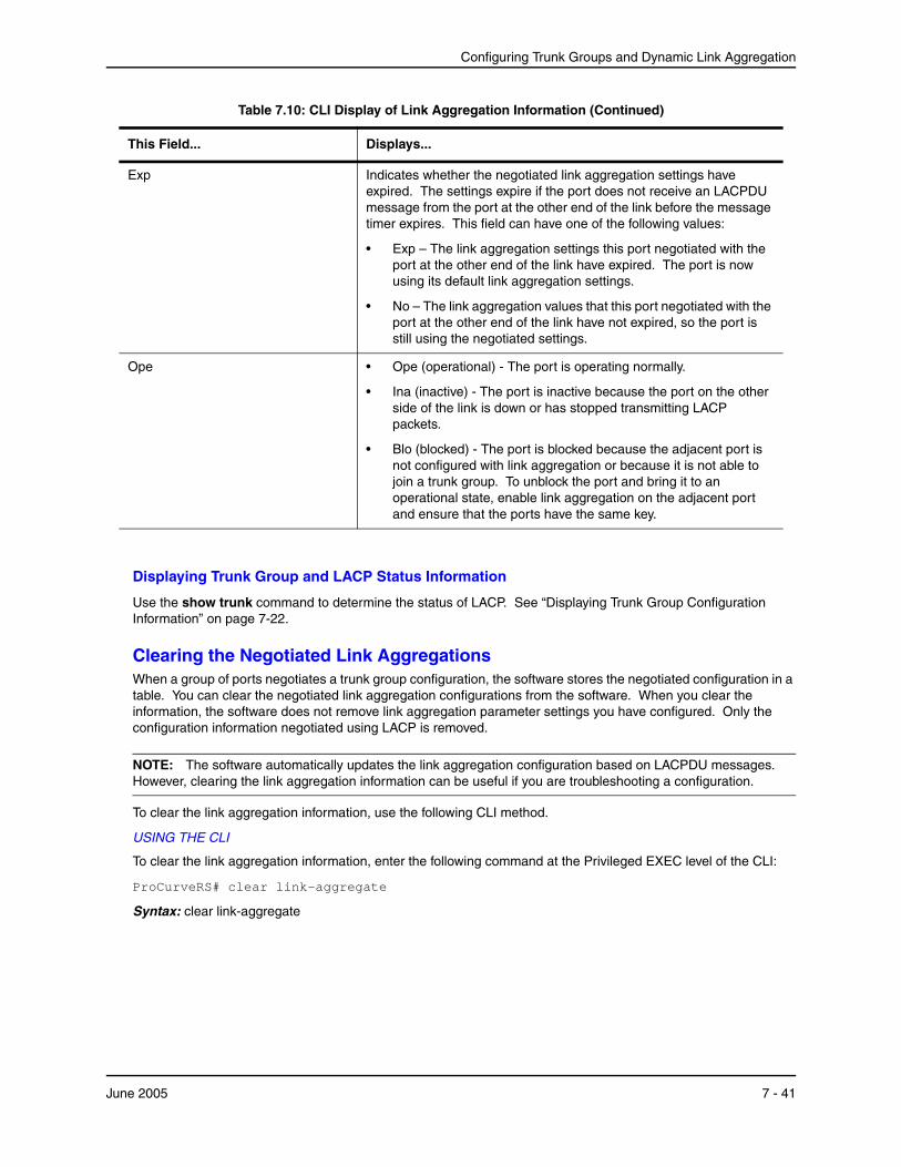
Configuring Trunk Groups and Dynamic Link Aggregation
Displaying Trunk Group and LACP Status Information
Use the show trunk command to determine the status of LACP. See “Displaying Trunk Group Configuration Information” on page 7-22.
Clearing the Negotiated Link AggregationsWhen a group of ports negotiates a trunk group configuration, the software stores the negotiated configuration in a table. You can clear the negotiated link aggregation configurations from the software. When you clear the information, the software does not remove link aggregation parameter settings you have configured. Only the configuration information negotiated using LACP is removed.
NOTE: The software automatically updates the link aggregation configuration based on LACPDU messages. However, clearing the link aggregation information can be useful if you are troubleshooting a configuration.
To clear the link aggregation information, use the following CLI method.
USING THE CLI
To clear the link aggregation information, enter the following command at the Privileged EXEC level of the CLI:
ProCurveRS# clear link-aggregate
Syntax: clear link-aggregate
Exp Indicates whether the negotiated link aggregation settings have expired. The settings expire if the port does not receive an LACPDU message from the port at the other end of the link before the message timer expires. This field can have one of the following values:
• Exp – The link aggregation settings this port negotiated with the port at the other end of the link have expired. The port is now using its default link aggregation settings.
• No – The link aggregation values that this port negotiated with the port at the other end of the link have not expired, so the port is still using the negotiated settings.
Ope • Ope (operational) - The port is operating normally.
• Ina (inactive) - The port is inactive because the port on the other side of the link is down or has stopped transmitting LACP packets.
• Blo (blocked) - The port is blocked because the adjacent port is not configured with link aggregation or because it is not able to join a trunk group. To unblock the port and bring it to an operational state, enable link aggregation on the adjacent port and ensure that the ports have the same key.
Table 7.10: CLI Display of Link Aggregation Information (Continued)
This Field... Displays...
June 2005 7 - 41

Installation and Basic Configuration Guide for ProCurve 9300 Series Routing Switches
7 - 42 June 2005
Chapter 8Configuring Spanning Tree Protocol (STP)
and Advanced STP Features
The Spanning Tree Protocol (STP) eliminates Layer 2 loops in networks, by selectively blocking some ports and allowing other ports to forward traffic, based on global (bridge) and local (port) parameters you can configure.
This chapter describes how to configure Spanning Tree Protocol (STP) parameters on HP ProCurve Routing Switches.
This chapter also describes advanced Layer 2 features that enable you to overcome limitations in the standard 802.1d Spanning Tree Protocol (STP). These are the advanced features:
• Fast Port Span
• Fast Uplink Span
• Single-instance STP
• SuperSpan
• STP per VLAN group
• Per VLAN Spanning Tree (PVST) and PVST+ Compatibility
Configuration procedures are provided for the standard STP bridge and port parameters as well as advanced STP parameters.
• To configure standard STP parameters, see “Configuring Standard STP Parameters”.
• To configure advanced parameters, see “Configuring Advanced STP Features” on page 8-19.
Configuring Standard STP ParametersProCurve Routing Switches support standard STP as described in the IEEE 802.1D specification. STP is disabled by default on Routing Switches.
By default, each port-based VLAN on an HP device runs a separate spanning tree (a separate instance of STP). An HP device has one port-based VLAN (VLAN 1) by default that contains all the device’s ports. Thus, by default each HP device has one spanning tree. However, if you configure additional port-based VLANs on an HP device, then each of those VLANs on which STP is enabled and VLAN 1 all run separate spanning trees.
If you configure a port-based VLAN on the device, the VLAN has the same STP state as the default STP state on the device. On Routing Switches, new VLANs have STP disabled by default. You can enable or disable STP in each VLAN separately. In addition, you can enable or disable STP on individual ports.
June 2005 8 - 1
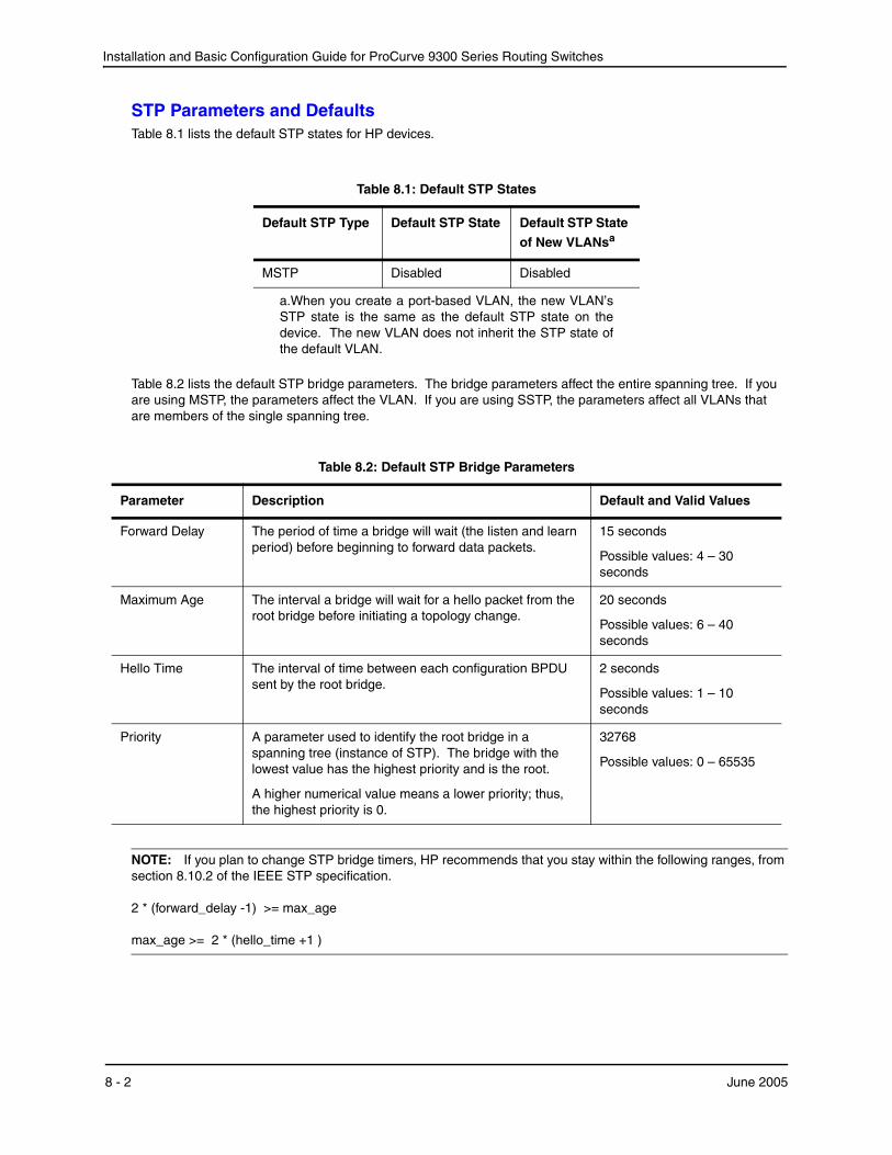
Installation and Basic Configuration Guide for ProCurve 9300 Series Routing Switches
STP Parameters and DefaultsTable 8.1 lists the default STP states for HP devices.
Table 8.1: Default STP States
Default STP Type Default STP State Default STP State of New VLANs
a.When you create a port-based VLAN, the new VLAN’s STP state is the same as the default STP state on the device. The new VLAN does not inherit the STP state of the default VLAN.
a
MSTP Disabled Disabled
Table 8.2 lists the default STP bridge parameters. The bridge parameters affect the entire spanning tree. If you are using MSTP, the parameters affect the VLAN. If you are using SSTP, the parameters affect all VLANs that are members of the single spanning tree.
Table 8.2: Default STP Bridge Parameters
Parameter Description Default and Valid Values
Forward Delay The period of time a bridge will wait (the listen and learn period) before beginning to forward data packets.
15 seconds
Possible values: 4 – 30 seconds
Maximum Age The interval a bridge will wait for a hello packet from the root bridge before initiating a topology change.
20 seconds
Possible values: 6 – 40 seconds
Hello Time The interval of time between each configuration BPDU sent by the root bridge.
2 seconds
Possible values: 1 – 10 seconds
Priority A parameter used to identify the root bridge in a spanning tree (instance of STP). The bridge with the lowest value has the highest priority and is the root.
A higher numerical value means a lower priority; thus, the highest priority is 0.
32768
Possible values: 0 – 65535
NOTE: If you plan to change STP bridge timers, HP recommends that you stay within the following ranges, from section 8.10.2 of the IEEE STP specification. 2 * (forward_delay -1) >= max_age max_age >= 2 * (hello_time +1 )
8 - 2 June 2005
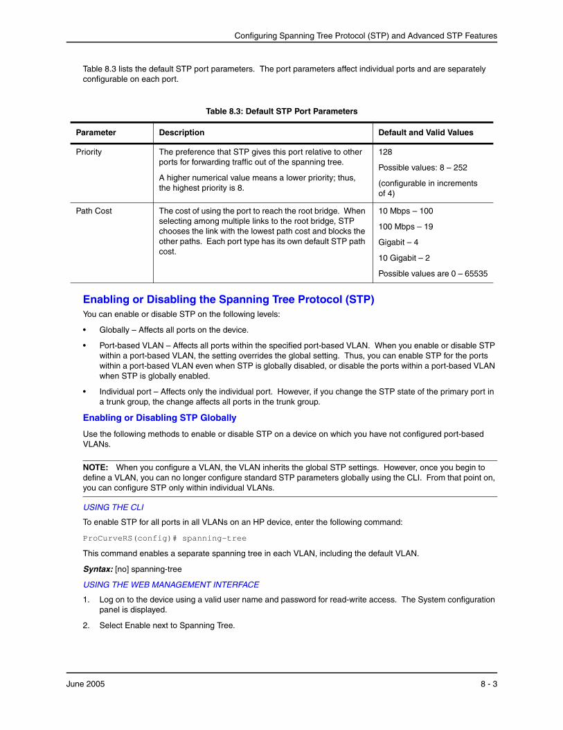
Configuring Spanning Tree Protocol (STP) and Advanced STP Features
Table 8.3 lists the default STP port parameters. The port parameters affect individual ports and are separately configurable on each port.
Table 8.3: Default STP Port Parameters
Parameter Description Default and Valid Values
Priority The preference that STP gives this port relative to other ports for forwarding traffic out of the spanning tree.
A higher numerical value means a lower priority; thus, the highest priority is 8.
128
Possible values: 8 – 252
(configurable in increments of 4)
Path Cost The cost of using the port to reach the root bridge. When selecting among multiple links to the root bridge, STP chooses the link with the lowest path cost and blocks the other paths. Each port type has its own default STP path cost.
10 Mbps – 100
100 Mbps – 19
Gigabit – 4
10 Gigabit – 2
Possible values are 0 – 65535
Enabling or Disabling the Spanning Tree Protocol (STP)You can enable or disable STP on the following levels:
• Globally – Affects all ports on the device.
• Port-based VLAN – Affects all ports within the specified port-based VLAN. When you enable or disable STP within a port-based VLAN, the setting overrides the global setting. Thus, you can enable STP for the ports within a port-based VLAN even when STP is globally disabled, or disable the ports within a port-based VLAN when STP is globally enabled.
• Individual port – Affects only the individual port. However, if you change the STP state of the primary port in a trunk group, the change affects all ports in the trunk group.
Enabling or Disabling STP Globally
Use the following methods to enable or disable STP on a device on which you have not configured port-based VLANs.
NOTE: When you configure a VLAN, the VLAN inherits the global STP settings. However, once you begin to define a VLAN, you can no longer configure standard STP parameters globally using the CLI. From that point on, you can configure STP only within individual VLANs.
USING THE CLI
To enable STP for all ports in all VLANs on an HP device, enter the following command:
ProCurveRS(config)# spanning-tree
This command enables a separate spanning tree in each VLAN, including the default VLAN.
Syntax: [no] spanning-tree
USING THE WEB MANAGEMENT INTERFACE
1. Log on to the device using a valid user name and password for read-write access. The System configuration panel is displayed.
2. Select Enable next to Spanning Tree.
June 2005 8 - 3
Installation and Basic Configuration Guide for ProCurve 9300 Series Routing Switches
NOTE: For information about the Single and Fast checkboxes, see “Single Spanning Tree (SSTP)” on page 8-62 and “Fast Uplink Span” on page 8-21.
3. Click Apply to save the changes to the device’s running-config file.
4. Select the Save link at the bottom of the dialog. Select Yes when prompted to save the configuration change to the startup-config file on the device’s flash memory.
Enabling or Disabling STP in a Port-Based VLAN
Use the following procedure to disable or enable STP on a device on which you have configured a port-based VLAN. Changing the STP state in a VLAN affects only that VLAN.
USING THE CLI
To enable STP for all ports in a port-based VLAN, enter commands such as the following:
ProCurveRS(config)# vlan 10 ProCurveRS(config-vlan-10)# spanning-tree
Syntax: [no] spanning-tree
USING THE WEB MANAGEMENT INTERFACE
You cannot enable or disable STP on individual VLANs using the Web management interface.
Enabling or Disabling STP on an Individual Port
Use the following procedure to disable or enable STP on an individual port.
NOTE: If you change the STP state of the primary port in a trunk group, the change affects all ports in the trunk group.
USING THE CLI
To enable STP on an individual port, enter commands such as the following:
ProCurveRS(config)# interface 1/1 ProCurveRS(config-if-1/1)# spanning-tree
Syntax: [no] spanning-tree
USING THE WEB MANAGEMENT INTERFACE
You cannot enable or disable STP on individual ports using the Web management interface.
Changing STP Bridge and Port ParametersTable 8.2 on page 8-2 and Table 8.3 on page 8-3 list the default STP parameters. If you need to change the default value for an STP parameter, use the following procedures.
Changing STP Bridge Parameters
To change STP bridge parameters, use either of the following methods.
NOTE: If you plan to change STP bridge timers, HP recommends that you stay within the following ranges, from section 8.10.2 of the IEEE STP specification. 2 * (forward_delay -1) >= max_age max_age >= 2 * (hello_time +1 )
USING THE CLI
To change an HP device’s STP bridge priority to the highest value to make the device the root bridge, enter the following command:
8 - 4 June 2005
Configuring Spanning Tree Protocol (STP) and Advanced STP Features
ProCurveRS(config)# spanning-tree priority 0
The command in this example changes the priority on a device on which you have not configured port-based VLANs. The change applies to the default VLAN. If you have configured a port-based VLAN on the device, you can configure the parameters only at the configuration level for individual VLANs. Enter commands such as the following:
ProCurveRS(config)# vlan 20 ProCurveRS(config-vlan-20)# spanning-tree priority 0
To make this change in the default VLAN, enter the following commands:
ProCurveRS(config)# vlan 1 ProCurveRS(config-vlan-1)# spanning-tree priority 0
Syntax: [no] spanning-tree [forward-delay <value>] | [hello-time <value>] | [maximum-age <value>] | [priority <value>]
The forward-delay <value> parameter specifies the forward delay and can be a value from 4 – 30 seconds. The default is 15 seconds.
NOTE: You can configure an HP device for faster convergence (including a shorter forward delay) using Fast Span or Fast Uplink Span. See “Configuring Advanced STP Features” on page 8-19.
The hello-time <value> parameter specifies the hello time and can be a value from 1 – 10 seconds. The default is 2 seconds.
NOTE: This parameter applies only when this device or VLAN is the root bridge for its spanning tree.
The maximum-age <value> parameter specifies the amount of time the device waits for receipt of a hello packet before initiating a topology change. You can specify from 6 – 40 seconds. The default is 20 seconds.
The priority <value> parameter specifies the priority and can be a value from 0 – 65535. A higher numerical value means a lower priority. Thus, the highest priority is 0. The default is 32768.
You can specify some or all of these parameters on the same command line. If you specify more than one parameter, you must specify them in the order shown above, from left to right.
USING THE WEB MANAGEMENT INTERFACE
To modify the STP parameters:
1. Log on to the device using a valid user name and password for read-write access. The System configuration panel is displayed.
2. Click on the plus sign next to Configure in the tree view to display the configuration options.
3. Select the STP link to display the STP bridge and port parameters.
June 2005 8 - 5
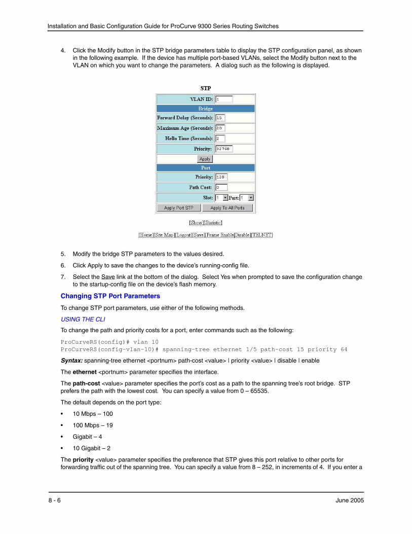
Installation and Basic Configuration Guide for ProCurve 9300 Series Routing Switches
4. Click the Modify button in the STP bridge parameters table to display the STP configuration panel, as shown in the following example. If the device has multiple port-based VLANs, select the Modify button next to the VLAN on which you want to change the parameters. A dialog such as the following is displayed.
5. Modify the bridge STP parameters to the values desired.
6. Click Apply to save the changes to the device’s running-config file.
7. Select the Save link at the bottom of the dialog. Select Yes when prompted to save the configuration change to the startup-config file on the device’s flash memory.
Changing STP Port Parameters
To change STP port parameters, use either of the following methods.
USING THE CLI
To change the path and priority costs for a port, enter commands such as the following:
ProCurveRS(config)# vlan 10 ProCurveRS(config-vlan-10)# spanning-tree ethernet 1/5 path-cost 15 priority 64
Syntax: spanning-tree ethernet <portnum> path-cost <value> | priority <value> | disable | enable
The ethernet <portnum> parameter specifies the interface.
The path-cost <value> parameter specifies the port’s cost as a path to the spanning tree’s root bridge. STP prefers the path with the lowest cost. You can specify a value from 0 – 65535.
The default depends on the port type:
• 10 Mbps – 100
• 100 Mbps – 19
• Gigabit – 4
• 10 Gigabit – 2
The priority <value> parameter specifies the preference that STP gives this port relative to other ports for forwarding traffic out of the spanning tree. You can specify a value from 8 – 252, in increments of 4. If you enter a
8 - 6 June 2005
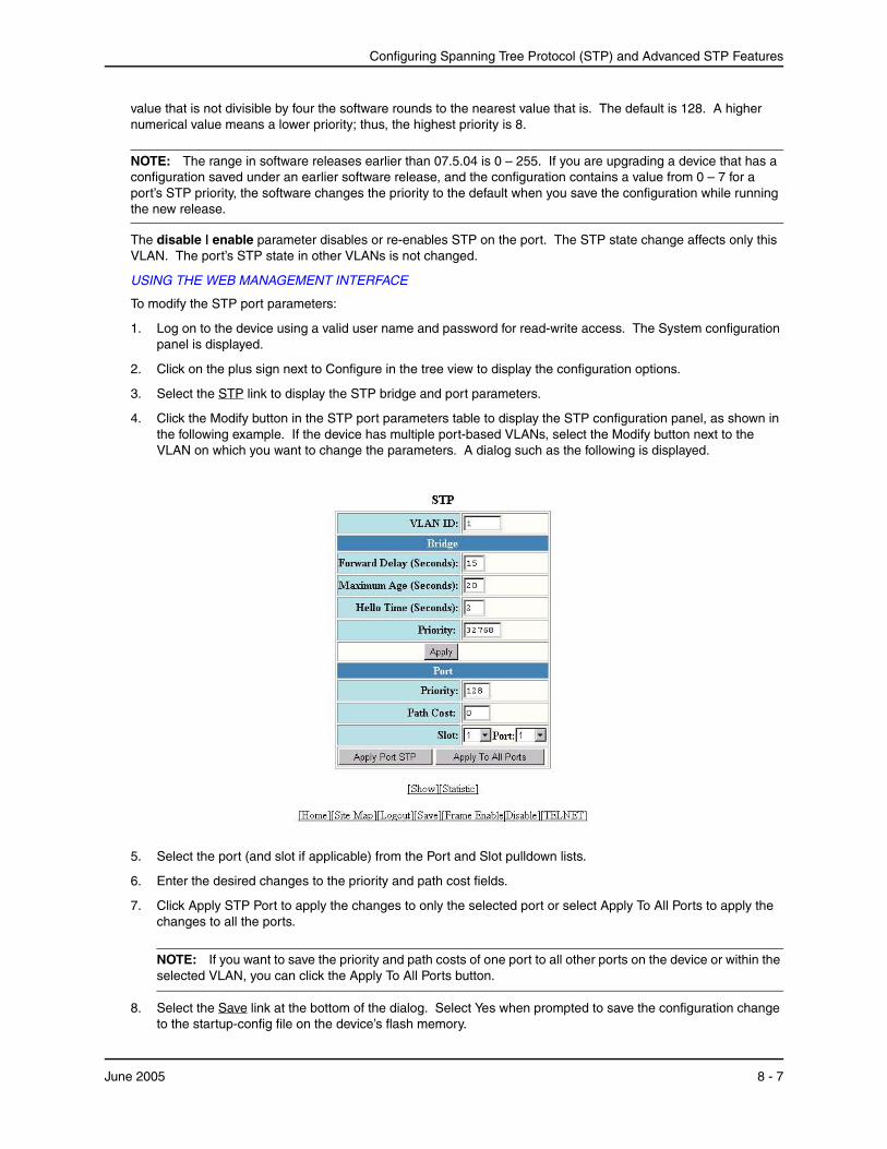
Configuring Spanning Tree Protocol (STP) and Advanced STP Features
value that is not divisible by four the software rounds to the nearest value that is. The default is 128. A higher numerical value means a lower priority; thus, the highest priority is 8.
NOTE: The range in software releases earlier than 07.5.04 is 0 – 255. If you are upgrading a device that has a configuration saved under an earlier software release, and the configuration contains a value from 0 – 7 for a port’s STP priority, the software changes the priority to the default when you save the configuration while running the new release.
The disable | enable parameter disables or re-enables STP on the port. The STP state change affects only this VLAN. The port’s STP state in other VLANs is not changed.
USING THE WEB MANAGEMENT INTERFACE
To modify the STP port parameters:
1. Log on to the device using a valid user name and password for read-write access. The System configuration panel is displayed.
2. Click on the plus sign next to Configure in the tree view to display the configuration options.
3. Select the STP link to display the STP bridge and port parameters.
4. Click the Modify button in the STP port parameters table to display the STP configuration panel, as shown in the following example. If the device has multiple port-based VLANs, select the Modify button next to the VLAN on which you want to change the parameters. A dialog such as the following is displayed.
5. Select the port (and slot if applicable) from the Port and Slot pulldown lists.
6. Enter the desired changes to the priority and path cost fields.
7. Click Apply STP Port to apply the changes to only the selected port or select Apply To All Ports to apply the changes to all the ports.
NOTE: If you want to save the priority and path costs of one port to all other ports on the device or within the selected VLAN, you can click the Apply To All Ports button.
8. Select the Save link at the bottom of the dialog. Select Yes when prompted to save the configuration change to the startup-config file on the device’s flash memory.
June 2005 8 - 7
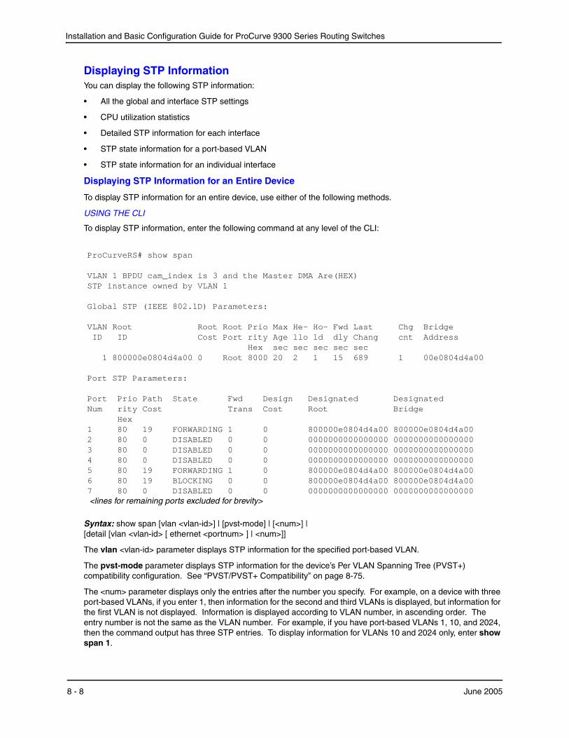
Installation and Basic Configuration Guide for ProCurve 9300 Series Routing Switches
Displaying STP InformationYou can display the following STP information:
• All the global and interface STP settings
• CPU utilization statistics
• Detailed STP information for each interface
• STP state information for a port-based VLAN
• STP state information for an individual interface
Displaying STP Information for an Entire Device
To display STP information for an entire device, use either of the following methods.
USING THE CLI
To display STP information, enter the following command at any level of the CLI:
ProCurveRS# show span VLAN 1 BPDU cam_index is 3 and the Master DMA Are(HEX) STP instance owned by VLAN 1 Global STP (IEEE 802.1D) Parameters: VLAN Root Root Root Prio Max He- Ho- Fwd Last Chg Bridge ID ID Cost Port rity Age llo ld dly Chang cnt Address Hex sec sec sec sec sec 1 800000e0804d4a00 0 Root 8000 20 2 1 15 689 1 00e0804d4a00 Port STP Parameters: Port Prio Path State Fwd Design Designated Designated Num rity Cost Trans Cost Root Bridge Hex 1 80 19 FORWARDING 1 0 800000e0804d4a00 800000e0804d4a00 2 80 0 DISABLED 0 0 0000000000000000 0000000000000000 3 80 0 DISABLED 0 0 0000000000000000 0000000000000000 4 80 0 DISABLED 0 0 0000000000000000 0000000000000000 5 80 19 FORWARDING 1 0 800000e0804d4a00 800000e0804d4a00 6 80 19 BLOCKING 0 0 800000e0804d4a00 800000e0804d4a00 7 80 0 DISABLED 0 0 0000000000000000 0000000000000000 <lines for remaining ports excluded for brevity>
Syntax: show span [vlan <vlan-id>] | [pvst-mode] | [<num>] | [detail [vlan <vlan-id> [ ethernet <portnum> ] | <num>]]
The vlan <vlan-id> parameter displays STP information for the specified port-based VLAN.
The pvst-mode parameter displays STP information for the device’s Per VLAN Spanning Tree (PVST+) compatibility configuration. See “PVST/PVST+ Compatibility” on page 8-75.
The <num> parameter displays only the entries after the number you specify. For example, on a device with three port-based VLANs, if you enter 1, then information for the second and third VLANs is displayed, but information for the first VLAN is not displayed. Information is displayed according to VLAN number, in ascending order. The entry number is not the same as the VLAN number. For example, if you have port-based VLANs 1, 10, and 2024, then the command output has three STP entries. To display information for VLANs 10 and 2024 only, enter show span 1.
8 - 8 June 2005
Configuring Spanning Tree Protocol (STP) and Advanced STP Features
The detail parameter and its additional optional parameters display detailed information for individual ports. See “Displaying Detailed STP Information for Each Interface” on page 8-14.
The show span command shows the following information.
Table 8.4: CLI Display of STP Information
This Field... Displays...
Global STP Parameters
VLAN ID The port-based VLAN that contains this spanning tree (instance of STP). VLAN 1 is the default VLAN. If you have not configured port-based VLANs on this device, all STP information is for VLAN 1.
Root ID The ID assigned by STP to the root bridge for this spanning tree.
Root Cost The cumulative cost from this bridge to the root bridge. If this device is the root bridge, then the root cost is 0.
Root Port The port on this device that connects to the root bridge. If this device is the root bridge, then the value is “Root” instead of a port number.
Priority Hex This device or VLAN’s STP priority. The value is shown in hexadecimal format.
Note: If you configure this value, specify it in decimal format. See “Changing STP Bridge Parameters” on page 8-4.
Max age sec The number of seconds this device or VLAN waits for a hello message from the root bridge before deciding the root has become unavailable and performing a reconvergence.
Hello sec The interval between each configuration BPDU sent by the root bridge.
Hold sec The minimum number of seconds that must elapse between transmissions of consecutive Configuration BPDUs on a port.
Fwd dly sec The number of seconds this device or VLAN waits following a topology change and consequent reconvergence.
Last Chang sec The number of seconds since the last time a topology change occurred.
Chg cnt The number of times the topology has changed since this device was reloaded.
Bridge Address The STP address of this device or VLAN.
Note: If this address is the same as the Root ID, then this device or VLAN is the root bridge for its spanning tree.
Port STP Parameters
Port Num The port number.
Priority Hex The port’s STP priority, in hexadecimal format.
Note: If you configure this value, specify it in decimal format. See “Changing STP Port Parameters” on page 8-6.
Path Cost The port’s STP path cost.
June 2005 8 - 9
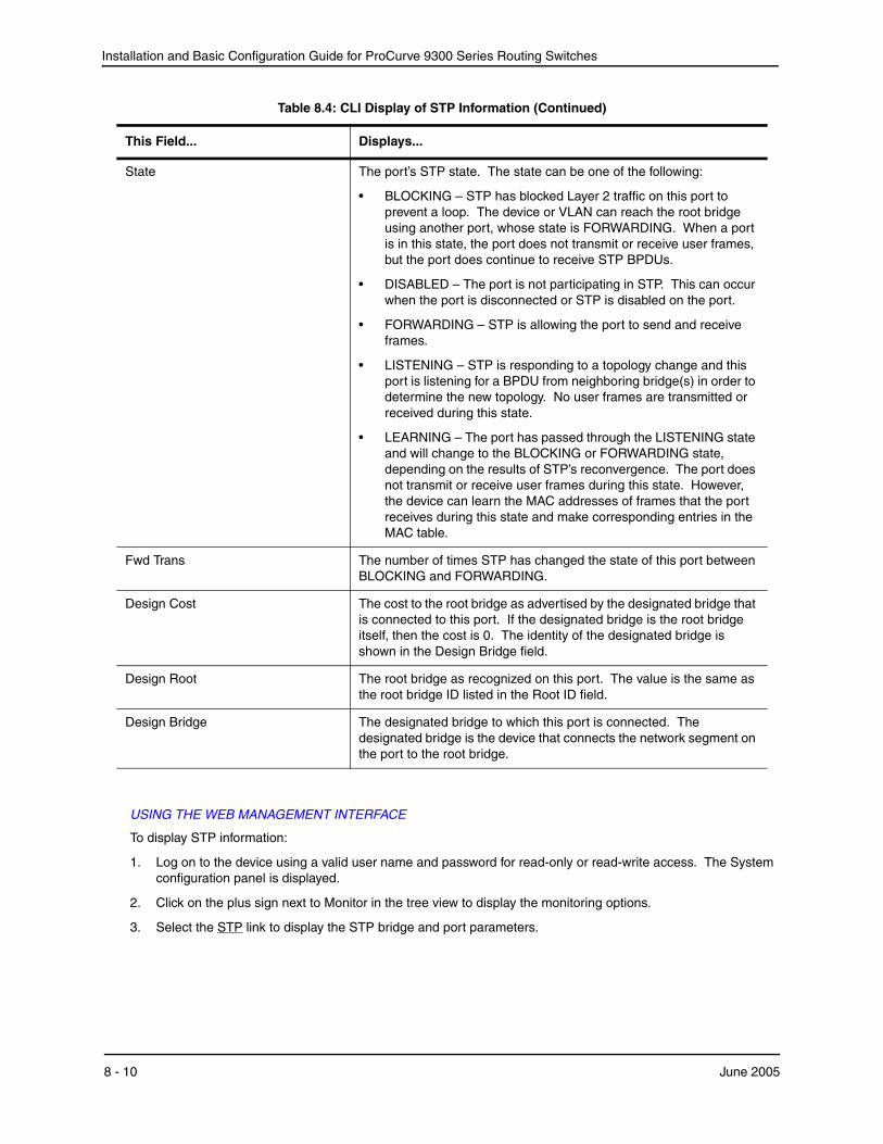
Installation and Basic Configuration Guide for ProCurve 9300 Series Routing Switches
USING THE WEB MANAGEMENT INTERFACE
To display STP information:
1. Log on to the device using a valid user name and password for read-only or read-write access. The System configuration panel is displayed.
2. Click on the plus sign next to Monitor in the tree view to display the monitoring options.
3. Select the STP link to display the STP bridge and port parameters.
State The port’s STP state. The state can be one of the following:
• BLOCKING – STP has blocked Layer 2 traffic on this port to prevent a loop. The device or VLAN can reach the root bridge using another port, whose state is FORWARDING. When a port is in this state, the port does not transmit or receive user frames, but the port does continue to receive STP BPDUs.
• DISABLED – The port is not participating in STP. This can occur when the port is disconnected or STP is disabled on the port.
• FORWARDING – STP is allowing the port to send and receive frames.
• LISTENING – STP is responding to a topology change and this port is listening for a BPDU from neighboring bridge(s) in order to determine the new topology. No user frames are transmitted or received during this state.
• LEARNING – The port has passed through the LISTENING state and will change to the BLOCKING or FORWARDING state, depending on the results of STP’s reconvergence. The port does not transmit or receive user frames during this state. However, the device can learn the MAC addresses of frames that the port receives during this state and make corresponding entries in the MAC table.
Fwd Trans The number of times STP has changed the state of this port between BLOCKING and FORWARDING.
Design Cost The cost to the root bridge as advertised by the designated bridge that is connected to this port. If the designated bridge is the root bridge itself, then the cost is 0. The identity of the designated bridge is shown in the Design Bridge field.
Design Root The root bridge as recognized on this port. The value is the same as the root bridge ID listed in the Root ID field.
Design Bridge The designated bridge to which this port is connected. The designated bridge is the device that connects the network segment on the port to the root bridge.
Table 8.4: CLI Display of STP Information (Continued)
This Field... Displays...
8 - 10 June 2005
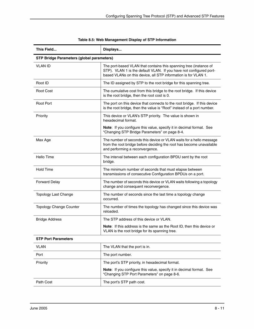
Configuring Spanning Tree Protocol (STP) and Advanced STP Features
Table 8.5: Web Management Display of STP Information
This Field... Displays...
STP Bridge Parameters (global parameters)
VLAN ID The port-based VLAN that contains this spanning tree (instance of STP). VLAN 1 is the default VLAN. If you have not configured port-based VLANs on this device, all STP information is for VLAN 1.
Root ID The ID assigned by STP to the root bridge for this spanning tree.
Root Cost The cumulative cost from this bridge to the root bridge. If this device is the root bridge, then the root cost is 0.
Root Port The port on this device that connects to the root bridge. If this device is the root bridge, then the value is “Root” instead of a port number.
Priority This device or VLAN’s STP priority. The value is shown in hexadecimal format.
Note: If you configure this value, specify it in decimal format. See “Changing STP Bridge Parameters” on page 8-4.
Max Age The number of seconds this device or VLAN waits for a hello message from the root bridge before deciding the root has become unavailable and performing a reconvergence.
Hello Time The interval between each configuration BPDU sent by the root bridge.
Hold Time The minimum number of seconds that must elapse between transmissions of consecutive Configuration BPDUs on a port.
Forward Delay The number of seconds this device or VLAN waits following a topology change and consequent reconvergence.
Topology Last Change The number of seconds since the last time a topology change occurred.
Topology Change Counter The number of times the topology has changed since this device was reloaded.
Bridge Address The STP address of this device or VLAN.
Note: If this address is the same as the Root ID, then this device or VLAN is the root bridge for its spanning tree.
STP Port Parameters
VLAN The VLAN that the port is in.
Port The port number.
Priority The port’s STP priority, in hexadecimal format.
Note: If you configure this value, specify it in decimal format. See “Changing STP Port Parameters” on page 8-6.
Path Cost The port’s STP path cost.
June 2005 8 - 11
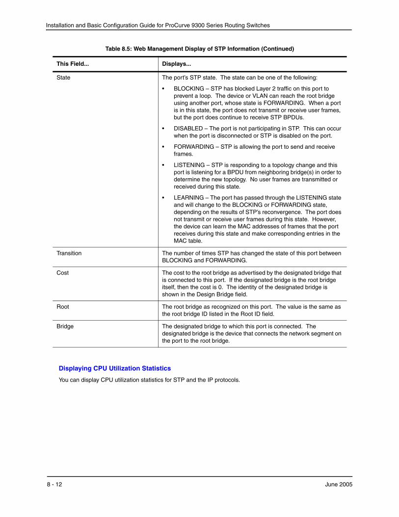
Installation and Basic Configuration Guide for ProCurve 9300 Series Routing Switches
Displaying CPU Utilization Statistics
You can display CPU utilization statistics for STP and the IP protocols.
State The port’s STP state. The state can be one of the following:
• BLOCKING – STP has blocked Layer 2 traffic on this port to prevent a loop. The device or VLAN can reach the root bridge using another port, whose state is FORWARDING. When a port is in this state, the port does not transmit or receive user frames, but the port does continue to receive STP BPDUs.
• DISABLED – The port is not participating in STP. This can occur when the port is disconnected or STP is disabled on the port.
• FORWARDING – STP is allowing the port to send and receive frames.
• LISTENING – STP is responding to a topology change and this port is listening for a BPDU from neighboring bridge(s) in order to determine the new topology. No user frames are transmitted or received during this state.
• LEARNING – The port has passed through the LISTENING state and will change to the BLOCKING or FORWARDING state, depending on the results of STP’s reconvergence. The port does not transmit or receive user frames during this state. However, the device can learn the MAC addresses of frames that the port receives during this state and make corresponding entries in the MAC table.
Transition The number of times STP has changed the state of this port between BLOCKING and FORWARDING.
Cost The cost to the root bridge as advertised by the designated bridge that is connected to this port. If the designated bridge is the root bridge itself, then the cost is 0. The identity of the designated bridge is shown in the Design Bridge field.
Root The root bridge as recognized on this port. The value is the same as the root bridge ID listed in the Root ID field.
Bridge The designated bridge to which this port is connected. The designated bridge is the device that connects the network segment on the port to the root bridge.
Table 8.5: Web Management Display of STP Information (Continued)
This Field... Displays...
8 - 12 June 2005
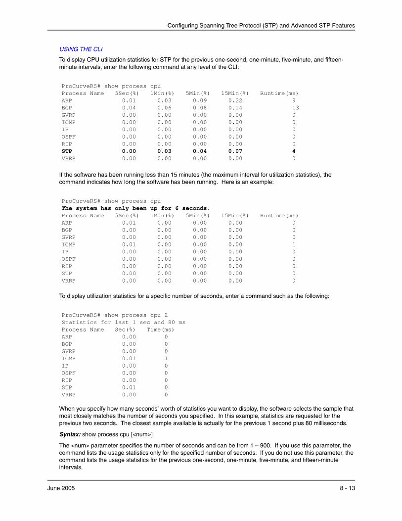
Configuring Spanning Tree Protocol (STP) and Advanced STP Features
USING THE CLI
To display CPU utilization statistics for STP for the previous one-second, one-minute, five-minute, and fifteen-minute intervals, enter the following command at any level of the CLI:
ProCurveRS# show process cpu Process Name 5Sec(%) 1Min(%) 5Min(%) 15Min(%) Runtime(ms) ARP 0.01 0.03 0.09 0.22 9 BGP 0.04 0.06 0.08 0.14 13 GVRP 0.00 0.00 0.00 0.00 0 ICMP 0.00 0.00 0.00 0.00 0 IP 0.00 0.00 0.00 0.00 0 OSPF 0.00 0.00 0.00 0.00 0 RIP 0.00 0.00 0.00 0.00 0 STP 0.00 0.03 0.04 0.07 4 VRRP 0.00 0.00 0.00 0.00 0
If the software has been running less than 15 minutes (the maximum interval for utilization statistics), the command indicates how long the software has been running. Here is an example:
ProCurveRS# show process cpu The system has only been up for 6 seconds. Process Name 5Sec(%) 1Min(%) 5Min(%) 15Min(%) Runtime(ms) ARP 0.01 0.00 0.00 0.00 0 BGP 0.00 0.00 0.00 0.00 0 GVRP 0.00 0.00 0.00 0.00 0 ICMP 0.01 0.00 0.00 0.00 1 IP 0.00 0.00 0.00 0.00 0 OSPF 0.00 0.00 0.00 0.00 0 RIP 0.00 0.00 0.00 0.00 0 STP 0.00 0.00 0.00 0.00 0 VRRP 0.00 0.00 0.00 0.00 0
To display utilization statistics for a specific number of seconds, enter a command such as the following:
ProCurveRS# show process cpu 2 Statistics for last 1 sec and 80 ms Process Name Sec(%) Time(ms) ARP 0.00 0 BGP 0.00 0 GVRP 0.00 0 ICMP 0.01 1 IP 0.00 0 OSPF 0.00 0 RIP 0.00 0 STP 0.01 0 VRRP 0.00 0
When you specify how many seconds’ worth of statistics you want to display, the software selects the sample that most closely matches the number of seconds you specified. In this example, statistics are requested for the previous two seconds. The closest sample available is actually for the previous 1 second plus 80 milliseconds.
Syntax: show process cpu [<num>]
The <num> parameter specifies the number of seconds and can be from 1 – 900. If you use this parameter, the command lists the usage statistics only for the specified number of seconds. If you do not use this parameter, the command lists the usage statistics for the previous one-second, one-minute, five-minute, and fifteen-minute intervals.
June 2005 8 - 13
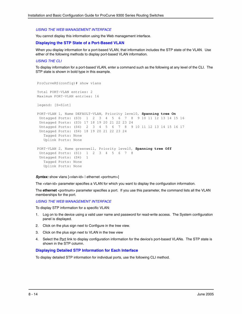
Installation and Basic Configuration Guide for ProCurve 9300 Series Routing Switches
USING THE WEB MANAGEMENT INTERFACE
You cannot display this information using the Web management interface.
Displaying the STP State of a Port-Based VLAN
When you display information for a port-based VLAN, that information includes the STP state of the VLAN. Use either of the following methods to display port-based VLAN information.
USING THE CLI
To display information for a port-based VLAN, enter a command such as the following at any level of the CLI. The STP state is shown in bold type in this example.
ProCurveRS(config)# show vlans Total PORT-VLAN entries: 2 Maximum PORT-VLAN entries: 16 legend: [S=Slot] PORT-VLAN 1, Name DEFAULT-VLAN, Priority level0, Spanning tree On Untagged Ports: (S3) 1 2 3 4 5 6 7 8 9 10 11 12 13 14 15 16 Untagged Ports: (S3) 17 18 19 20 21 22 23 24 Untagged Ports: (S4) 2 3 4 5 6 7 8 9 10 11 12 13 14 15 16 17 Untagged Ports: (S4) 18 19 20 21 22 23 24 Tagged Ports: None Uplink Ports: None PORT-VLAN 2, Name greenwell, Priority level0, Spanning tree Off Untagged Ports: (S1) 1 2 3 4 5 6 7 8 Untagged Ports: (S4) 1 Tagged Ports: None Uplink Ports: None
Syntax: show vlans [<vlan-id> | ethernet <portnum>]
The <vlan-id> parameter specifies a VLAN for which you want to display the configuration information.
The ethernet <portnum> parameter specifies a port. If you use this parameter, the command lists all the VLAN memberships for the port.
USING THE WEB MANAGEMENT INTERFACE
To display STP information for a specific VLAN:
1. Log on to the device using a valid user name and password for read-write access. The System configuration panel is displayed.
2. Click on the plus sign next to Configure in the tree view.
3. Click on the plus sign next to VLAN in the tree view
4. Select the Port link to display configuration information for the device’s port-based VLANs. The STP state is shown in the STP column.
Displaying Detailed STP Information for Each Interface
To display detailed STP information for individual ports, use the following CLI method.
8 - 14 June 2005
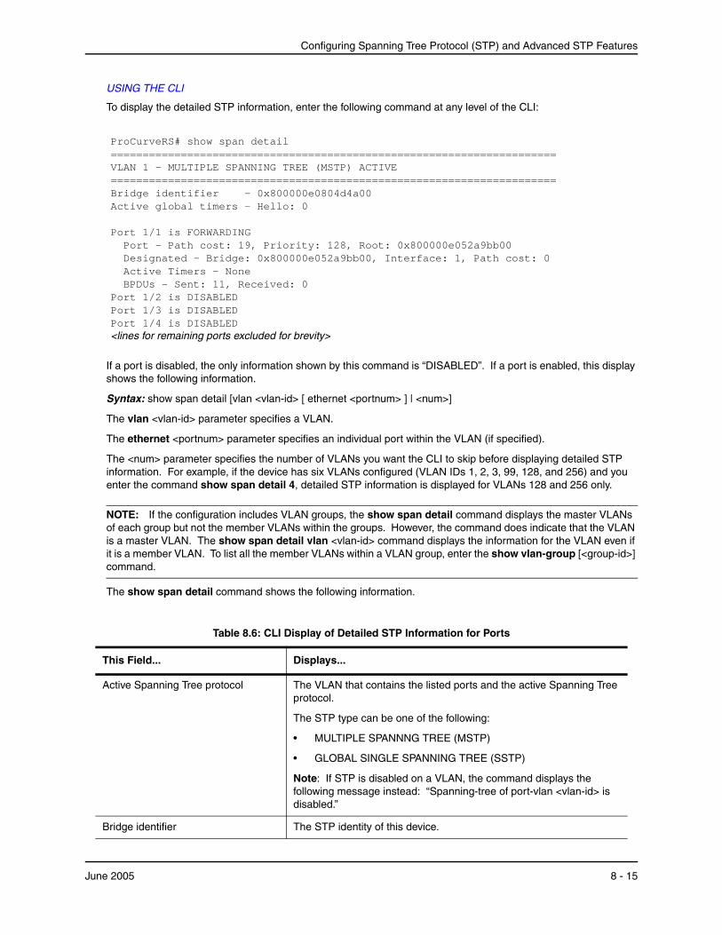
Configuring Spanning Tree Protocol (STP) and Advanced STP Features
USING THE CLI
To display the detailed STP information, enter the following command at any level of the CLI:
ProCurveRS# show span detail ====================================================================== VLAN 1 - MULTIPLE SPANNING TREE (MSTP) ACTIVE ====================================================================== Bridge identifier - 0x800000e0804d4a00 Active global timers - Hello: 0 Port 1/1 is FORWARDING Port - Path cost: 19, Priority: 128, Root: 0x800000e052a9bb00 Designated - Bridge: 0x800000e052a9bb00, Interface: 1, Path cost: 0 Active Timers - None BPDUs - Sent: 11, Received: 0 Port 1/2 is DISABLED Port 1/3 is DISABLED Port 1/4 is DISABLED <lines for remaining ports excluded for brevity>
If a port is disabled, the only information shown by this command is “DISABLED”. If a port is enabled, this display shows the following information.
Syntax: show span detail [vlan <vlan-id> [ ethernet <portnum> ] | <num>]
The vlan <vlan-id> parameter specifies a VLAN.
The ethernet <portnum> parameter specifies an individual port within the VLAN (if specified).
The <num> parameter specifies the number of VLANs you want the CLI to skip before displaying detailed STP information. For example, if the device has six VLANs configured (VLAN IDs 1, 2, 3, 99, 128, and 256) and you enter the command show span detail 4, detailed STP information is displayed for VLANs 128 and 256 only.
NOTE: If the configuration includes VLAN groups, the show span detail command displays the master VLANs of each group but not the member VLANs within the groups. However, the command does indicate that the VLAN is a master VLAN. The show span detail vlan <vlan-id> command displays the information for the VLAN even if it is a member VLAN. To list all the member VLANs within a VLAN group, enter the show vlan-group [<group-id>] command.
The show span detail command shows the following information.
Table 8.6: CLI Display of Detailed STP Information for Ports
This Field... Displays...
Active Spanning Tree protocol The VLAN that contains the listed ports and the active Spanning Tree protocol.
The STP type can be one of the following:
• MULTIPLE SPANNNG TREE (MSTP)
• GLOBAL SINGLE SPANNING TREE (SSTP)
Note: If STP is disabled on a VLAN, the command displays the following message instead: “Spanning-tree of port-vlan <vlan-id> is disabled.”
Bridge identifier The STP identity of this device.
June 2005 8 - 15
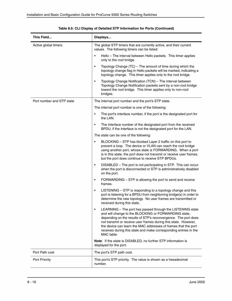
Installation and Basic Configuration Guide for ProCurve 9300 Series Routing Switches
Active global timers The global STP timers that are currently active, and their current values. The following timers can be listed:
• Hello – The interval between Hello packets. This timer applies only to the root bridge.
• Topology Change (TC) – The amount of time during which the topology change flag in Hello packets will be marked, indicating a topology change. This timer applies only to the root bridge.
• Topology Change Notification (TCN) – The interval between Topology Change Notification packets sent by a non-root bridge toward the root bridge. This timer applies only to non-root bridges.
Port number and STP state The internal port number and the port’s STP state.
The internal port number is one of the following:
• The port’s interface number, if the port is the designated port for the LAN.
• The interface number of the designated port from the received BPDU, if the interface is not the designated port for the LAN.
The state can be one of the following:
• BLOCKING – STP has blocked Layer 2 traffic on this port to prevent a loop. The device or VLAN can reach the root bridge using another port, whose state is FORWARDING. When a port is in this state, the port does not transmit or receive user frames, but the port does continue to receive STP BPDUs.
• DISABLED – The port is not participating in STP. This can occur when the port is disconnected or STP is administratively disabled on the port.
• FORWARDING – STP is allowing the port to send and receive frames.
• LISTENING – STP is responding to a topology change and this port is listening for a BPDU from neighboring bridge(s) in order to determine the new topology. No user frames are transmitted or received during this state.
• LEARNING – The port has passed through the LISTENING state and will change to the BLOCKING or FORWARDING state, depending on the results of STP’s reconvergence. The port does not transmit or receive user frames during this state. However, the device can learn the MAC addresses of frames that the port receives during this state and make corresponding entries in the MAC table.
Note: If the state is DISABLED, no further STP information is displayed for the port.
Port Path cost The port’s STP path cost.
Port Priority This port’s STP priority. The value is shown as a hexadecimal number.
Table 8.6: CLI Display of Detailed STP Information for Ports (Continued)
This Field... Displays...
8 - 16 June 2005
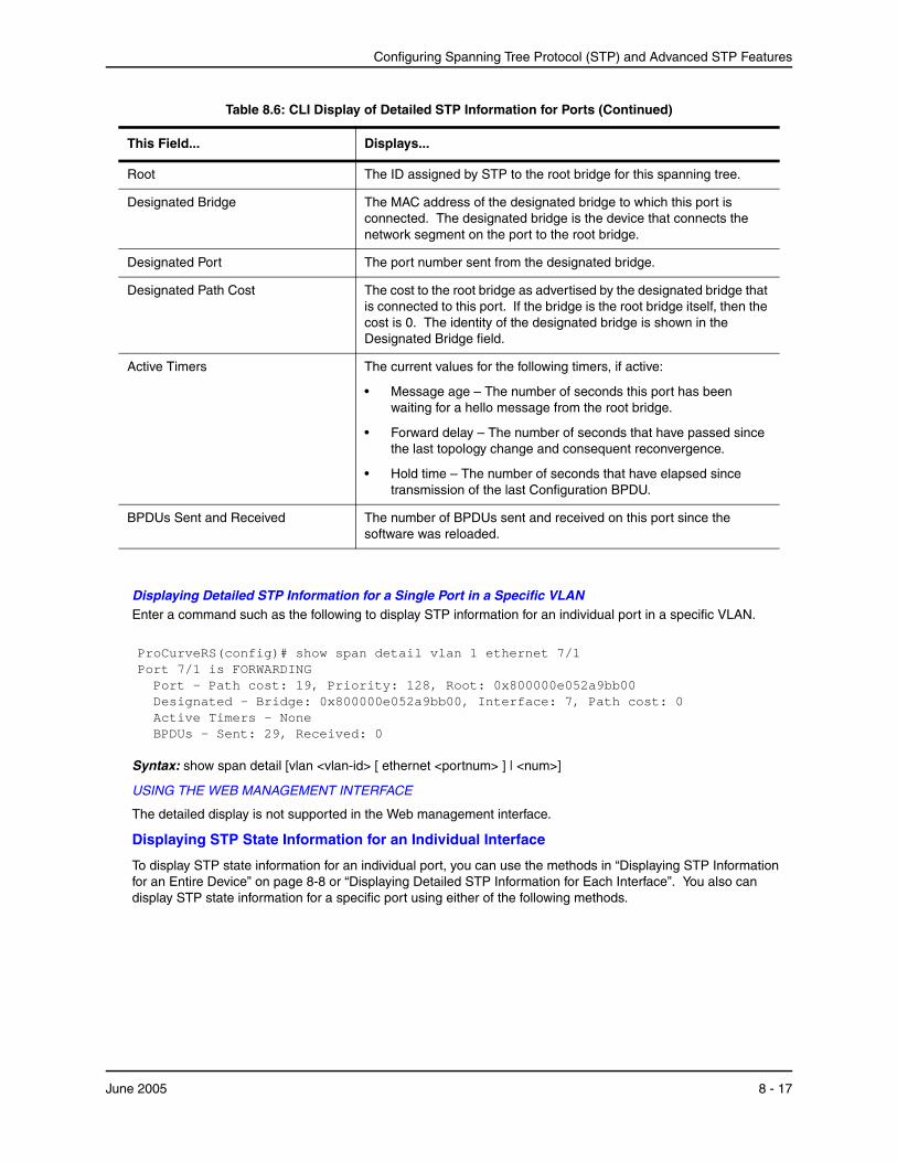
Configuring Spanning Tree Protocol (STP) and Advanced STP Features
Displaying Detailed STP Information for a Single Port in a Specific VLANEnter a command such as the following to display STP information for an individual port in a specific VLAN.
ProCurveRS(config)# show span detail vlan 1 ethernet 7/1 Port 7/1 is FORWARDING Port - Path cost: 19, Priority: 128, Root: 0x800000e052a9bb00 Designated - Bridge: 0x800000e052a9bb00, Interface: 7, Path cost: 0 Active Timers - None BPDUs - Sent: 29, Received: 0
Syntax: show span detail [vlan <vlan-id> [ ethernet <portnum> ] | <num>]
USING THE WEB MANAGEMENT INTERFACE
The detailed display is not supported in the Web management interface.
Displaying STP State Information for an Individual Interface
To display STP state information for an individual port, you can use the methods in “Displaying STP Information for an Entire Device” on page 8-8 or “Displaying Detailed STP Information for Each Interface”. You also can display STP state information for a specific port using either of the following methods.
Root The ID assigned by STP to the root bridge for this spanning tree.
Designated Bridge The MAC address of the designated bridge to which this port is connected. The designated bridge is the device that connects the network segment on the port to the root bridge.
Designated Port The port number sent from the designated bridge.
Designated Path Cost The cost to the root bridge as advertised by the designated bridge that is connected to this port. If the bridge is the root bridge itself, then the cost is 0. The identity of the designated bridge is shown in the Designated Bridge field.
Active Timers The current values for the following timers, if active:
• Message age – The number of seconds this port has been waiting for a hello message from the root bridge.
• Forward delay – The number of seconds that have passed since the last topology change and consequent reconvergence.
• Hold time – The number of seconds that have elapsed since transmission of the last Configuration BPDU.
BPDUs Sent and Received The number of BPDUs sent and received on this port since the software was reloaded.
Table 8.6: CLI Display of Detailed STP Information for Ports (Continued)
This Field... Displays...
June 2005 8 - 17
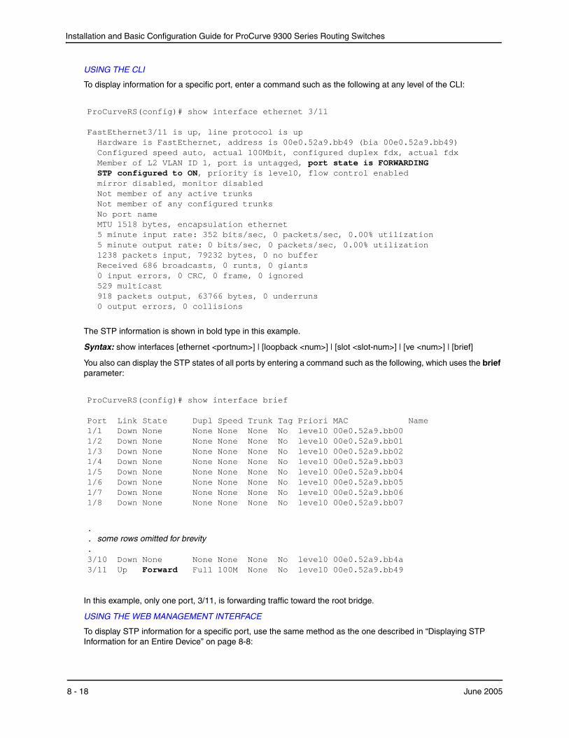
Installation and Basic Configuration Guide for ProCurve 9300 Series Routing Switches
USING THE CLI
To display information for a specific port, enter a command such as the following at any level of the CLI:
ProCurveRS(config)# show interface ethernet 3/11 FastEthernet3/11 is up, line protocol is up Hardware is FastEthernet, address is 00e0.52a9.bb49 (bia 00e0.52a9.bb49) Configured speed auto, actual 100Mbit, configured duplex fdx, actual fdx Member of L2 VLAN ID 1, port is untagged, port state is FORWARDING STP configured to ON, priority is level0, flow control enabled mirror disabled, monitor disabled Not member of any active trunks Not member of any configured trunks No port name MTU 1518 bytes, encapsulation ethernet 5 minute input rate: 352 bits/sec, 0 packets/sec, 0.00% utilization 5 minute output rate: 0 bits/sec, 0 packets/sec, 0.00% utilization 1238 packets input, 79232 bytes, 0 no buffer Received 686 broadcasts, 0 runts, 0 giants 0 input errors, 0 CRC, 0 frame, 0 ignored 529 multicast 918 packets output, 63766 bytes, 0 underruns 0 output errors, 0 collisions
The STP information is shown in bold type in this example.
Syntax: show interfaces [ethernet <portnum>] | [loopback <num>] | [slot <slot-num>] | [ve <num>] | [brief]
You also can display the STP states of all ports by entering a command such as the following, which uses the brief parameter:
ProCurveRS(config)# show interface brief Port Link State Dupl Speed Trunk Tag Priori MAC Name 1/1 Down None None None None No level0 00e0.52a9.bb00 1/2 Down None None None None No level0 00e0.52a9.bb01 1/3 Down None None None None No level0 00e0.52a9.bb02 1/4 Down None None None None No level0 00e0.52a9.bb03 1/5 Down None None None None No level0 00e0.52a9.bb04 1/6 Down None None None None No level0 00e0.52a9.bb05 1/7 Down None None None None No level0 00e0.52a9.bb06 1/8 Down None None None None No level0 00e0.52a9.bb07
.
. some rows omitted for brevity
. 3/10 Down None None None None No level0 00e0.52a9.bb4a 3/11 Up Forward Full 100M None No level0 00e0.52a9.bb49
In this example, only one port, 3/11, is forwarding traffic toward the root bridge.
USING THE WEB MANAGEMENT INTERFACE
To display STP information for a specific port, use the same method as the one described in “Displaying STP Information for an Entire Device” on page 8-8:
8 - 18 June 2005

Configuring Spanning Tree Protocol (STP) and Advanced STP Features
1. Log on to the device using a valid user name and password for read-only or read-write access. The System configuration panel is displayed.
2. Click on the plus sign next to Monitor in the tree view to display the monitoring options.
3. Select the STP link to display the STP bridge and port parameters.
Configuring Advanced STP FeaturesThis section describes how to configure the following features:
• Fast Port Span – see “Fast Port Span”
• Fast Uplink Span – see “Fast Uplink Span” on page 8-21
• 802.1W Rapid Spanning Tree (RSTP) – see “802.1W Rapid Spanning Tree (RSTP)” on page 8-22
• 802.1W Draft 3 RSTP – see “802.1W Draft 3” on page 8-58
• Single-instance STP – see “Single Spanning Tree (SSTP)” on page 8-62
• SuperSpan – see “SuperSpan™” on page 8-64
• STP per VLAN group – see “STP per VLAN Group” on page 8-71
• Per VLAN Spanning Tree+ (PVST+) Compatibility – see “PVST/PVST+ Compatibility” on page 8-75
Fast Port SpanWhen STP is running on a device, message forwarding is delayed during the spanning tree recalculation period following a topology change. The STP forward delay parameter specifies the period of time a bridge waits before forwarding data packets. The forward delay controls the listening and learning periods of STP reconvergence. You can configure the forward delay to a value from 4 – 30 seconds. The default is 15 seconds. Thus, using the standard forward delay, convergence requires 30 seconds (15 seconds for listening and an additional 15 seconds for learning) when the default value is used.
This slow convergence is undesirable and unnecessary in some circumstances. The Fast Port Span feature allows certain ports to enter the forwarding state in four seconds. Specifically, Fast Port Span allows faster convergence on ports that are attached to end stations and thus do not present the potential to cause Layer 2 forwarding loops. Because the end stations cannot cause forwarding loops, they can safely go through the STP state changes (blocking to listening to learning to forwarding) more quickly than is allowed by the standard STP convergence time. Fast Port Span performs the convergence on these ports in four seconds (two seconds for listening and two seconds for learning).
In addition, Fast Port Span enhances overall network performance in the following ways:
• Fast Port Span reduces the number of STP topology change notifications on the network. When an end station attached to a Fast Span port comes up or down, the HP device does not generate a topology change notification for the port. In this situation, the notification is unnecessary since a change in the state of the host does not affect the network’s topology.
• Fast Port Span eliminates unnecessary MAC cache aging that can be caused by topology change notifications. Bridging devices age out the learned MAC addresses in their MAC caches if the addresses are unrefreshed for a given period of time, sometimes called the MAC aging interval. When STP sends a topology change notification, devices that receive the notification use the value of the STP forward delay to quickly age out their MAC caches. For example, if a device’s normal MAC aging interval is 5 minutes, the aging interval changes temporarily to the value of the forward delay (for example, 15 seconds) in response to an STP topology change. In normal STP, the accelerated cache aging occurs even when a single host goes up or down. Because Fast Port Span does not send a topology change notification when a host on a Fast Port Span port goes up or down, the unnecessary cache aging that can occur in these circumstances under normal STP is eliminated.
Fast Port Span is a system-wide parameter and is enabled by default. Thus, when you boot a device with software release 06.6.05 or later, all the ports that are attached only to end stations run Fast Port Span. For ports that are
June 2005 8 - 19

Installation and Basic Configuration Guide for ProCurve 9300 Series Routing Switches
not eligible for Fast Port Span, such as ports connected to other networking devices, the device automatically uses the normal STP settings. If a port matches any of the following criteria, the port is ineligible for Fast Port Span and uses normal STP instead:
• The port is 802.1q tagged
• The port is a member of a trunk group
• The port has learned more than one active MAC address
• An STP Configuration BPDU has been received on the port, thus indicating the presence of another bridge on the port.
You also can explicitly exclude individual ports from Fast Port Span if needed. For example, if the only uplink ports for a wiring closet switch are Gigabit ports, you can exclude the ports from Fast Port Span.
Disabling and Re-enabling Fast Port Span
Fast Port Span is a system-wide parameter and is enabled by default. Thus all ports that are eligible for Fast Port Span use it.
To disable or re-enable Fast Port Span, use one of the following methods.
USING THE CLI
To disable Fast Port Span, enter the following commands:
ProCurveRS(config)# no fast port-span ProCurveRS(config)# write memory
Syntax: [no] fast port-span
NOTE: The fast port-span command has additional parameters that let you exclude specific ports. These parameters are shown in the following section.
To re-enable Fast Port Span, enter the following commands:
ProCurveRS(config)# fast port-span ProCurveRS(config)# write memory
USING THE WEB MANAGEMENT INTERFACE
1. Log on to the device using a valid user name and password for read-write access.
2. Click the Fast checkbox next to Spanning Tree to remove the checkmark from the box.
3. Click Apply to apply the change to the device’s running-config.
4. Select the Save link at the bottom of the panel. Select Yes when prompted to save the configuration change to the startup-config file on the device’s flash memory.
Excluding Specific Ports from Fast Port Span
You can exclude individual ports from Fast Port Span while leaving Fast Port Span enabled globally. To do so, use one of the following methods.
USING THE CLI
To exclude a port from Fast Port Span, enter commands such as the following:
ProCurveRS(config)# fast port-span exclude ethernet 1/1 ProCurveRS(config)# write memory
To exclude a set of ports from Fast Port Span, enter commands such as the following:
ProCurveRS(config)# fast port-span exclude ethernet 1/1 ethernet 2/1 ethernet 3/2 ProCurveRS(config)# write memory
To exclude a contiguous (unbroken) range of ports from Fast Span, enter commands such as the following:
ProCurveRS(config)# fast port-span exclude ethernet 1/1 to 1/24
8 - 20 June 2005

Configuring Spanning Tree Protocol (STP) and Advanced STP Features
ProCurveRS(config)# write memory
Syntax: [no] fast port-span [exclude ethernet <portnum> [ethernet <portnum>… | to <portnum>]]
To re-enable Fast Port Span on a port, enter a command such as the following:
ProCurveRS(config)# no fast port-span exclude ethernet 1/1 ProCurveRS(config)# write memory
This command re-enables Fast Port Span on port 1/1 only and does not re-enable Fast Port Span on other excluded ports. You also can re-enable Fast Port Span on a list or range of ports using the syntax shown above this example.
To re-enable Fast Port Span on all excluded ports, disable and then re-enable Fast Port Span by entering the following commands:
ProCurveRS(config)# no fast port-span ProCurveRS(config)# fast port-span ProCurveRS(config)# write memory
Disabling and then re-enabling Fast Port Span clears the exclude settings and thus enables Fast Port Span on all eligible ports. To make sure Fast Port Span remains enabled on the ports following a system reset, save the configuration changes to the startup-config file after you re-enable Fast Port Span. Otherwise, when the system resets, those ports will again be excluded from Fast Port Span.
USING THE WEB MANAGEMENT INTERFACE
You cannot exclude individual ports from Fast Span using the Web management interface.
Fast Uplink SpanThe Fast Port Span feature described in the previous section enhances STP performance for end stations. The Fast Uplink feature enhances STP performance for wiring closet switches with redundant uplinks. Using the default value for the standard STP forward delay, convergence following a transition from an active link to a redundant link can take 30 seconds (15 seconds for listening and an additional 15 seconds for learning).
You can use the Fast Uplink feature on an HP device deployed as a wiring closet switch to decrease the convergence time for the uplink ports to another device to just four seconds (two seconds for listening and two seconds for learning). The wiring closet switch must be an HP device but the device at the other end of the link can be an HP device or another vendor’s switch. Configuration of the Fast Uplink Span feature takes place entirely on the HP device.
To configure the Fast Uplink Span feature, specify a group of ports that have redundant uplinks on the wiring closet switch (HP device) as members of a Fast Uplink Group. If the active link becomes unavailable, the Fast Uplink Span feature transitions the forwarding to one of the other ports in four seconds. You can configure one Fast Uplink Span group on the device. All Fast Uplink Span ports are members of the same Fast Uplink Span group.
NOTE: To avoid the potential for temporary bridging loops, Hewlett-Packard recommends that you use the Fast Uplink feature only for wiring closet switches (switches at the edge of the network cloud). In addition, enable the feature only on a group of ports intended for redundancy, so that at any given time only one of the ports is expected to be in the forwarding state.
Fast Uplink Span Rules for Trunk Groups
If you add a port to a Fast Uplink Span group that is a member of a trunk group, the following rules apply:
• If you add the primary port of a trunk group to the Fast Uplink Span group, all other ports in the trunk group are automatically included in the group. Similarly, if you remove the primary port in a trunk group from the Fast Uplink Span group, the other ports in the trunk group are automatically removed from the Fast Uplink Span group.
• You cannot add a subset of the ports in a trunk group to the Fast Uplink Span group. All ports in a trunk group have the same Fast Uplink Span property, as they do for other port properties.
June 2005 8 - 21
Installation and Basic Configuration Guide for ProCurve 9300 Series Routing Switches
• If the working trunk group is partially down but not completely down, no switch-over to the backup occurs. This behavior is the same as in the standard STP feature.
• If the working trunk group is completely down, a backup trunk group can go through an accelerated transition only if the following are true:
• The trunk group is included in the fast uplink group.
• All other ports except those in this trunk group are either disabled or blocked. The accelerated transition applies to all ports in this trunk group.
• When the original working trunk group comes back (partially or fully), the transition back to the original topology is accelerated if the conditions listed above are met.
Configuring a Fast Uplink Port Group
To enable Fast Uplink, use one of the following methods.
USING THE CLI
To configure a group of ports for Fast Uplink Span, enter the following commands:
ProCurveRS(config)# fast uplink-span ethernet 4/1 to 4/4 ProCurveRS(config)# write memory
Syntax: [no] fast uplink-span [ethernet <portnum> [ethernet <portnum>… | to <portnum>]]
This example configures four ports, 4/1 – 4/4, as a Fast Uplink Span group. In this example, all four ports are connected to a wiring closet switch. Only one of the links is expected to be active at any time. The other links are redundant. For example, if the link on port 4/1 is the active link on the wiring closet switch but becomes unavailable, one of the other links takes over. Because the ports are configured in a Fast Uplink Span group, the STP convergence takes about four seconds instead of taking 30 seconds or longer using the standard STP forward delay.
If you add a port that is the primary port of a trunk group, all ports in the trunk group become members of the Fast Uplink Span group.
You can add ports to a Fast Uplink Span group by entering the fast uplink-span command additional times with additional ports. The device can have only one Fast Uplink Span group, so all the ports you identify as Fast Uplink Span ports are members of the same group.
To remove a Fast Uplink Span group or to remove individual ports from a group, use “no” in front of the appropriate fast uplink-span command. For example, to remove ports 4/3 and 4/4 from the Fast Uplink Span group configured above, enter the following commands:
ProCurveRS(config)# no fast uplink-span ethernet 4/3 to 4/4 ProCurveRS(config)# write memory
If you delete a port that is the primary port of a trunk group, all ports in the trunk group are removed from the Fast Uplink Span group.
USING THE WEB MANAGEMENT INTERFACE
You cannot configure the Fast Uplink Span feature using the Web management interface.
802.1W Rapid Spanning Tree (RSTP)HP’s earlier implementation of Rapid Spanning Tree Protocol (RSTP), which was 802.1W Draft 3, provided only a subset of the IEEE 802.1W standard; whereas the 802.1W RSTP feature provides the full standard. The implementation of the 802.1W Draft 3 is referred to as RSTP Draft 3.
RSTP Draft3 will continue to be supported on HP devices for backward compatibility. However, customers who are currently using RSTP Draft 3 should migrate to 802.1W.
The 802.1W feature is supported on all Routing Switches. It provides rapid traffic reconvergence for point-to-point links within a few milliseconds (0 – 500 milliseconds), following the failure of a bridge or bridge port. This reconvergence occurs more rapidly than the reconvergence provided by the 802.1D (Spanning Tree Protocol (STP)) or by RSTP Draft 3.
8 - 22 June 2005
Configuring Spanning Tree Protocol (STP) and Advanced STP Features
NOTE: This rapid convergence will not occur on ports connected to shared media devices, such as hubs. To take advantage of the rapid convergence provided by 802.1W, make sure to explicitly configure all point-to-point links in a topology.
The convergence provided by the standard 802.1W protocol occurs more rapidly than the convergence provided by previous spanning tree protocols because:
• Classic or legacy 802.1D STP protocol requires a newly selected Root port to go through listening and learning stages before traffic convergence can be achieved. The 802.1D traffic convergence time is calculated using the following formula:
2 x FORWARD_DELAY + BRIDGE_MAX_AGE.
If default values are used in the parameter configuration, convergence can take up to 50 seconds. (In this document STP will be referred to as 802.1D.)
• RSTP Draft 3 works only on bridges that have Alternate ports, which are the precalculated “next best root port”. (Alternate ports provide back up paths to the root bridge.) Although convergence occurs from 0 – 500 milliseconds in RSTP Draft 3, the spanning tree topology reverts to the 802.1D convergence if an Alternate port is not found.
• Convergence in 802.1w bridge is not based on any timer values. Rather, it is based on the explicit handshakes between Designated ports and their connected Root ports to achieve convergence in less than 500 milliseconds.
Bridges and Bridge Port Roles
A bridge in an 802.1W rapid spanning tree topology is assigned as the root bridge if it has the highest priority (lowest bridge identifier) in the topology. Other bridges are referred to as non-root bridges.
Unique roles are assigned to ports on the root and non-root bridges. Role assignments are based on the following information contained in the Rapid Spanning Tree Bridge Packet Data Unit (RST BPDU):
• Root bridge ID
• Path cost value
• Transmitting bridge ID
• Designated port ID
802.1W algorithm uses this information to determine if the RST BPDU received by a port is superior to the RST BPDU that the port transmits. The two values are compared in the order as given above, starting with the Root bridge ID. The RST BPDU with a lower value is considered superior. The superiority and inferiority of the RST BPDU is used to assign a role to a port.
If the value of the received RST BPDU is the same as that of the transmitted RST BPDU, then the port ID in the RST BPDUs are compared. The RST BPDU with the lower port ID is superior. Port roles are then calculated appropriately.
The port’s role is included in the BPDU that it transmits. The BPDU transmitted by an 802.1W port is referred to as an RST BPDU, while it is operating in 802.1W mode.
Ports can have one of the following roles:
• Root – Provides the lowest cost path to the root bridge from a specific bridge
• Designated – Provides the lowest cost path to the root bridge from a LAN to which it is connected
• Alternate – Provides an alternate path to the root bridge when the root port goes down
• Backup – Provides a backup to the LAN when the Designated port goes down
• Disabled – Has no role in the topology
June 2005 8 - 23
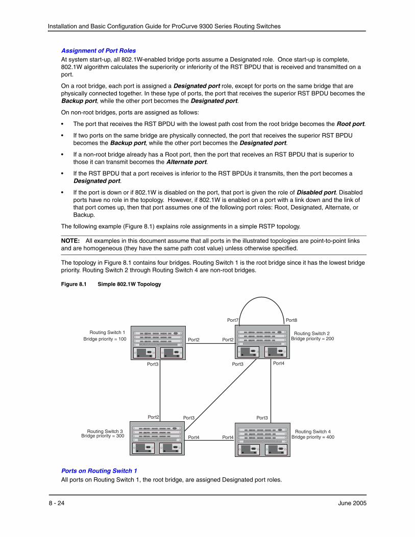
Installation and Basic Configuration Guide for ProCurve 9300 Series Routing Switches
Assignment of Port RolesAt system start-up, all 802.1W-enabled bridge ports assume a Designated role. Once start-up is complete, 802.1W algorithm calculates the superiority or inferiority of the RST BPDU that is received and transmitted on a port.
On a root bridge, each port is assigned a Designated port role, except for ports on the same bridge that are physically connected together. In these type of ports, the port that receives the superior RST BPDU becomes the Backup port, while the other port becomes the Designated port.
On non-root bridges, ports are assigned as follows:
• The port that receives the RST BPDU with the lowest path cost from the root bridge becomes the Root port.
• If two ports on the same bridge are physically connected, the port that receives the superior RST BPDU becomes the Backup port, while the other port becomes the Designated port.
• If a non-root bridge already has a Root port, then the port that receives an RST BPDU that is superior to those it can transmit becomes the Alternate port.
• If the RST BPDU that a port receives is inferior to the RST BPDUs it transmits, then the port becomes a Designated port.
• If the port is down or if 802.1W is disabled on the port, that port is given the role of Disabled port. Disabled ports have no role in the topology. However, if 802.1W is enabled on a port with a link down and the link of that port comes up, then that port assumes one of the following port roles: Root, Designated, Alternate, or Backup.
The following example (Figure 8.1) explains role assignments in a simple RSTP topology.
NOTE: All examples in this document assume that all ports in the illustrated topologies are point-to-point links and are homogeneous (they have the same path cost value) unless otherwise specified.
The topology in Figure 8.1 contains four bridges. Routing Switch 1 is the root bridge since it has the lowest bridge priority. Routing Switch 2 through Routing Switch 4 are non-root bridges.
Figure 8.1 Simple 802.1W Topology
Port2 Port2
Port7 Port8
Port3
Port3
Port4Port4
Port3
Port2 Port3
Bridge priority = 200
Bridge priority = 400Bridge priority = 300
Bridge priority = 100Routing Switch 1
Routing Switch 3 Routing Switch 4
Routing Switch 2
Port4
Ports on Routing Switch 1All ports on Routing Switch 1, the root bridge, are assigned Designated port roles.
8 - 24 June 2005

Configuring Spanning Tree Protocol (STP) and Advanced STP Features
Ports on Routing Switch 2Port2 on Routing Switch 2 directly connects to the root bridge; therefore, Port2 is the Root port.
Routing Switch 2’s bridge priority value is superior to that of Routing Switch 3 and Routing Switch 4; therefore, the ports on Routing Switch 2 that connect to Routing Switch 3 and Routing Switch 4 are given the Designated port role.
Furthermore, Port7 and Port8 on Routing Switch 2 are physically connected. The RST BPDUs transmitted by Port7 are superior to those Port8 transmits. Therefore, Routing Switch 2 Port8 is the Backup port and Port7 is the Designated port.
Ports on Routing Switch 3Port2 on Routing Switch 3 directly connects to the Designated port on the root bridge; therefore, it assumes the Root port role.
The root path cost of the RST BPDUs received on Port4/Routing Switch 3 is inferior to the RST BPDUs transmitted by the port; therefore, Port4/Routing Switch 3 becomes the Designated port.
Similarly Routing Switch 3 has a bridge priority value inferior to Routing Switch 2. Port3 on Routing Switch 3 connects to Port 3 on Routing Switch 2. This port will be given the Alternate port role, since a Root port is already established on this bridge.
Ports Routing Switch 4Routing Switch 4 is not directly connected to the root bridge. It has two ports with superior incoming RST BPDUs from two separate LANs: Port3 and Port4. The RST BPDUs received on Port3 are superior to the RST BPDUs received on port 4; therefore, Port3 becomes the Root port and Port4 becomes the Alternate port.
Edge Ports and Edge Port Roles
HP’s implementation of 802.1W allows ports that are configured as Edge ports to be present in an 802.1W topology. (Figure 8.2). Edge ports are ports of a bridge that connect to workstations or computers. Edge ports do not register any incoming BPDU activities.
Edge ports assume Designated port roles. Port flapping does not cause any topology change events on Edge ports since 802.1W does not consider Edge ports in the spanning tree calculations.
June 2005 8 - 25
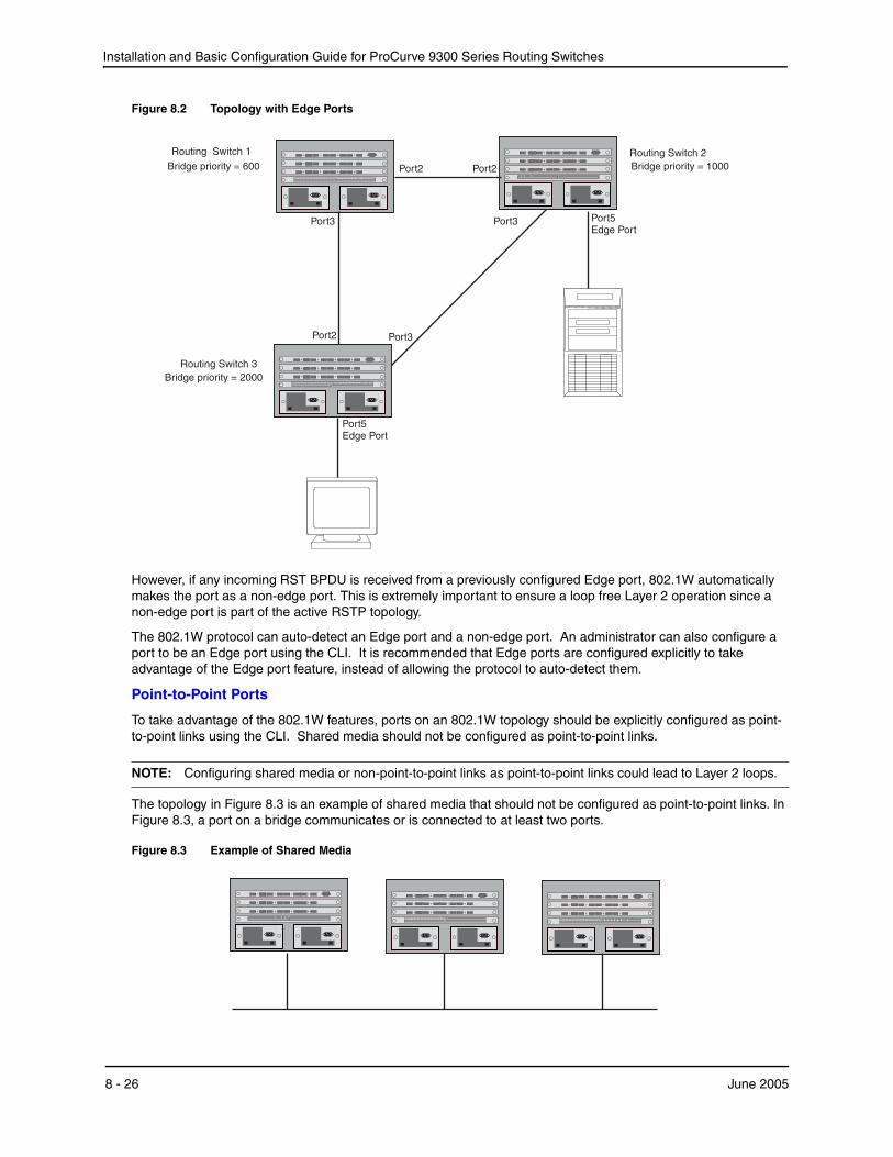
Installation and Basic Configuration Guide for ProCurve 9300 Series Routing Switches
Figure 8.2 Topology with Edge Ports
Port2 Port2
Port3Port3
Port2 Port3
Bridge priority = 1000
Bridge priority = 2000
Bridge priority = 600
Port5Edge Port
Port5Edge Port
Routing 1Switch
Routing Switch 3
Routing 2Switch
However, if any incoming RST BPDU is received from a previously configured Edge port, 802.1W automatically makes the port as a non-edge port. This is extremely important to ensure a loop free Layer 2 operation since a non-edge port is part of the active RSTP topology.
The 802.1W protocol can auto-detect an Edge port and a non-edge port. An administrator can also configure a port to be an Edge port using the CLI. It is recommended that Edge ports are configured explicitly to take advantage of the Edge port feature, instead of allowing the protocol to auto-detect them.
Point-to-Point Ports
To take advantage of the 802.1W features, ports on an 802.1W topology should be explicitly configured as point-to-point links using the CLI. Shared media should not be configured as point-to-point links.
NOTE: Configuring shared media or non-point-to-point links as point-to-point links could lead to Layer 2 loops.
The topology in Figure 8.3 is an example of shared media that should not be configured as point-to-point links. In Figure 8.3, a port on a bridge communicates or is connected to at least two ports.
Figure 8.3 Example of Shared Media
8 - 26 June 2005
Configuring Spanning Tree Protocol (STP) and Advanced STP Features
Bridge Port States
Ports roles can have one of the following states:
• Forwarding – 802.1W is allowing the port to send and receive all packets.
• Discarding – 802.1W has blocked data traffic on this port to prevent a loop. The device or VLAN can reach the root bridge using another port, whose state is forwarding. When a port is in this state, the port does not transmit or receive data frames, but the port does continue to receive RST BPDUs. This state corresponds to the listening and blocking states of 802.1D.
• Learning – 802.1W is allowing MAC entries to be added to the filtering database but does not permit forwarding of data frames. The device can learn the MAC addresses of frames that the port receives during this state and make corresponding entries in the MAC table.
• Disabled – The port is not participating in 802.1W. This can occur when the port is disconnected or 802.1W is administratively disabled on the port.
A port on a non-root bridge with the role of Root port is always in a forwarding state. If another port on that bridge assumes the Root port role, then the old Root port moves into a discarding state as it assumes another port role.
A port on a non-root bridge with a Designated role starts in the discarding state. When that port becomes elected to the Root port role, 802.1W quickly places it into a forwarding state. However, if the Designated port is an Edge port, then the port starts and stays in a forwarding state and it cannot be elected as a Root port.
A port with an Alternate or Backup role is always in a discarding state. If the port’s role changes to Designated, then the port changes into a forwarding state.
If a port on one bridge has a Designated role and that port is connected to a port on another bridge that has an Alternate or Backup role, the port with a Designated role cannot be given a Root port role until two instances of the forward delay timer expires on that port.
Edge Port and Non-Edge Port States
As soon as a port is configured as an Edge port using the CLI, it goes into a forwarding state instantly (in less than 100 msec):
When the link to a port comes up and 802.1W detects that the port is an Edge port, that port instantly goes into a forwarding state.
If 802.1W detects that port as a non-edge port, the port goes into a forwarding state within four seconds of link up or after two hello timer expires on the port.
Changes to Port Roles and States
To achieve convergence in a topology, a port’s role and state changes as it receives and transmits new RST BPDUs. Changes in a port’s role and state constitute a topology change. Besides the superiority and inferiority of the RST BPDU, bridge-wide and per-port state machines are used to determine a port’s role as well as a port’s state. Port state machines also determine when port role and state changes occur.
State MachinesThe bridge uses the Port Role Selection state machine to determine if port role changes are required on the bridge. This state machine performs a computation when one of the following events occur:
• New information is received on any port on the bridge
• The timer expires for the current information on a port on the bridge
Each port uses the following state machines:
• Port Information – This state machine keeps track of spanning-tree information currently used by the port. It records the origin of the information and ages out any information that was derived from an incoming BPDU.
• Port Role Transition – This state machine keeps track of the current port role and transitions the port to the appropriate role when required. It moves the Root port and the Designated port into forwarding states and moves the Alternate and Backup ports into discarding states.
• Port Transmit – This state machine is responsible for BPDU transmission. It checks to ensure only the
June 2005 8 - 27

Installation and Basic Configuration Guide for ProCurve 9300 Series Routing Switches
maximum number of BPDUs per hello interval are sent every second. Based on what mode it is operating in, it sends out either legacy BPDUs or RST BPDUs. In this document legacy BPDUs are also referred to as STP BPDUs.
• Port Protocol Migration – This state machine deals with compatibility with 802.1D bridges. When a legacy BPDU is detected on a port, this state machine configures the port to transmit and receive legacy BPDUs and operate in the legacy mode.
• Topology Change – This state machine detects, generates, and propagates topology change notifications. It acknowledges Topology Change Notice (TCN) messages when operating in 802.1D mode. It also flushes the MAC table when a topology change event takes place.
• Port State Transition – This state machine transitions the port to a discarding, learning, or forwarding state and performs any necessary processing associated with the state changes.
• Port Timers – This state machine is responsible for triggering any of the state machines described above, based on expiration of specific port timers.
In contrast to the 802.1D standard, the 802.1W standard does not have any bridge specific timers. All timers in the CLI are applied on a per-port basis, even though they are configured under bridge parameters.
802.1W state machines attempt to quickly place the ports into either a forwarding or discarding state. Root ports are quickly placed in forwarding state when both of the following events occur:
• It is assigned to be the Root port.
• It receives an RST BPDU with a proposal flag from a Designated port. The proposal flag is sent by ports with a Designated role when they are ready to move into a forwarding state.
When a the role of Root port is given to another port, the old Root port is instructed to reroot. The old Root port goes into a discarding state and negotiates with its peer port for a new role and a new state. A peer port is the port on the other bridge to which the port is connected. For example, in Figure 8.4, Port1 of Routing Switch 200 is the peer port of Port2 of Routing Switch 100.
A port with a Designated role is quickly placed into a forwarding state if one of the following occurs:
• The Designated port receives an RST BPDU that contains an agreement flag from a Root port
• The Designated port is an Edge port
However, a Designated port that is attached to an Alternate port or a Backup port must wait until the forward delay timer expires twice on that port while it is still in a Designated role, before it can proceed to the forwarding state.
Backup ports are quickly placed into discarding states.
Alternate ports are quickly placed into discarding states.
A port operating in 802.1W mode may enter a learning state to allow MAC entries to be added to the filtering database; however, this state is transient and lasts only a few milliseconds, if the port is operating in 802.1W mode and if the port meets the conditions for rapid transition.
Handshake Mechanisms To rapidly transition a Designated or Root port into a forwarding state, the Port Role Transition state machine uses handshake mechanisms to ensure loop free operations. It uses one type of handshake if no Root port has been assigned on a bridge, and another type if a Root port has already been assigned.
Handshake When No Root Port is ElectedIf a Root port has not been assigned on a bridge, 802.1W uses the Proposing -> Proposed -> Sync -> Synced -> Agreed handshake:
• Proposing – The Designated port on the root bridge sends an RST BPDU packet to its peer port that contains a proposal flag. The proposal flag is a signal that indicates that the Designated port is ready to put itself in a forwarding state (Figure 8.4). The Designated port continues to send this flag in its RST BPDU until it is placed in a forwarding state (Figure 8.7) or is forced to operate in 802.1D mode. (See “Compatibility of 802.1W with 802.1D” on page 48.)
• Proposed – When a port receives an RST BPDU with a proposal flag from the Designated port on its point-to-
8 - 28 June 2005
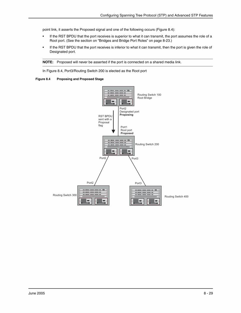
Configuring Spanning Tree Protocol (STP) and Advanced STP Features
point link, it asserts the Proposed signal and one of the following occurs (Figure 8.4):
• If the RST BPDU that the port receives is superior to what it can transmit, the port assumes the role of a Root port. (See the section on “Bridges and Bridge Port Roles” on page 8-23.)
• If the RST BPDU that the port receives is inferior to what it can transmit, then the port is given the role of Designated port.
NOTE: Proposed will never be asserted if the port is connected on a shared media link.
In Figure 8.4, Port3/Routing Switch 200 is elected as the Root port
Figure 8.4 Proposing and Proposed Stage
Routing Switch 100Root Bridge
Routing Switch 200
Routing Switch 400Routing Switch 300
Port2Designated portProposing
Port1Root portProposed
Port2
Port2 Port3
Port3
RST BPDUsent with aProposalflag
June 2005 8 - 29
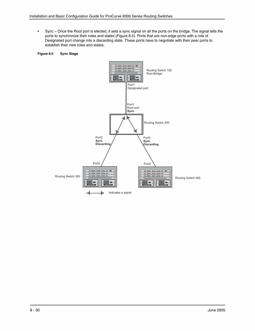
Installation and Basic Configuration Guide for ProCurve 9300 Series Routing Switches
• Sync – Once the Root port is elected, it sets a sync signal on all the ports on the bridge. The signal tells the ports to synchronize their roles and states (Figure 8.5). Ports that are non-edge ports with a role of Designated port change into a discarding state. These ports have to negotiate with their peer ports to establish their new roles and states.
Figure 8.5 Sync Stage
Routing Switch 100Root Bridge
Routing Switch 200
Routing Switch 400Routing Switch 300
Port1Designated port
Port1Root portSync
Port2SyncDiscarding
Port2 Port3
Port3SyncDiscarding
Indicates a signal
8 - 30 June 2005
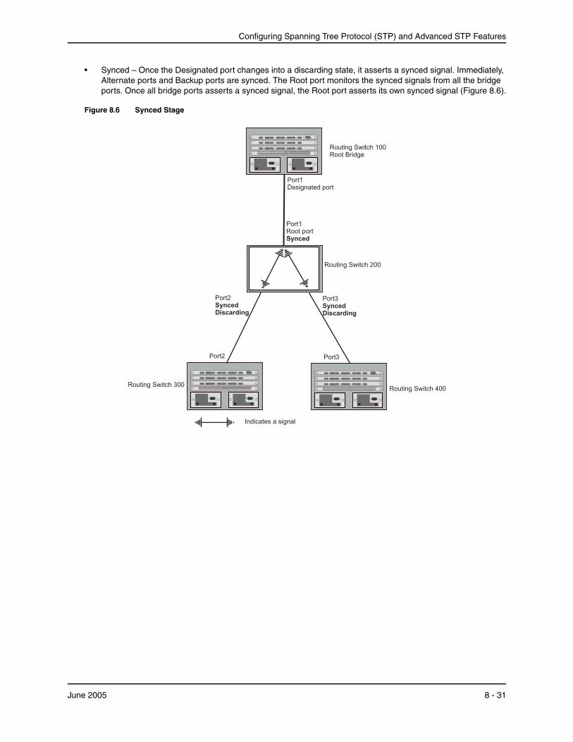
Configuring Spanning Tree Protocol (STP) and Advanced STP Features
• Synced – Once the Designated port changes into a discarding state, it asserts a synced signal. Immediately, Alternate ports and Backup ports are synced. The Root port monitors the synced signals from all the bridge ports. Once all bridge ports asserts a synced signal, the Root port asserts its own synced signal (Figure 8.6).
Figure 8.6 Synced Stage
Routing Switch 100Root Bridge
Routing Switch 200
Routing Switch 400Routing Switch 300
Port1Designated port
Port1Root portSynced
Port2SyncedDiscarding
Port2 Port3
Port3SyncedDiscarding
Indicates a signal
June 2005 8 - 31
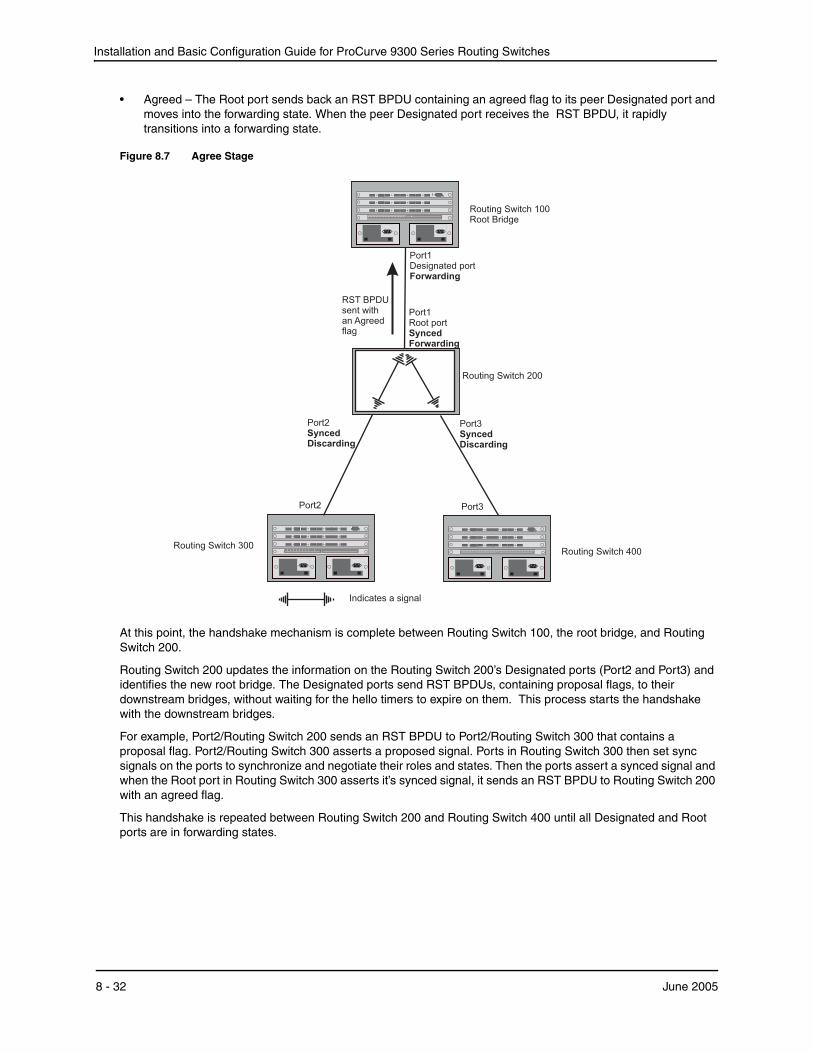
Installation and Basic Configuration Guide for ProCurve 9300 Series Routing Switches
• Agreed – The Root port sends back an RST BPDU containing an agreed flag to its peer Designated port and moves into the forwarding state. When the peer Designated port receives the RST BPDU, it rapidly transitions into a forwarding state.
Figure 8.7 Agree Stage
Routing Switch 100Root Bridge
Routing Switch 200
Routing Switch 400Routing Switch 300
Port1Designated portForwarding
Port1Root portSyncedForwarding
Port2SyncedDiscarding
Port2 Port3
Port3SyncedDiscarding
RST BPDUsent withan Agreedflag
Indicates a signal
At this point, the handshake mechanism is complete between Routing Switch 100, the root bridge, and Routing Switch 200.
Routing Switch 200 updates the information on the Routing Switch 200’s Designated ports (Port2 and Port3) and identifies the new root bridge. The Designated ports send RST BPDUs, containing proposal flags, to their downstream bridges, without waiting for the hello timers to expire on them. This process starts the handshake with the downstream bridges.
For example, Port2/Routing Switch 200 sends an RST BPDU to Port2/Routing Switch 300 that contains a proposal flag. Port2/Routing Switch 300 asserts a proposed signal. Ports in Routing Switch 300 then set sync signals on the ports to synchronize and negotiate their roles and states. Then the ports assert a synced signal and when the Root port in Routing Switch 300 asserts it’s synced signal, it sends an RST BPDU to Routing Switch 200 with an agreed flag.
This handshake is repeated between Routing Switch 200 and Routing Switch 400 until all Designated and Root ports are in forwarding states.
8 - 32 June 2005

Configuring Spanning Tree Protocol (STP) and Advanced STP Features
Handshake When a Root Port Has Been ElectedIf a non-root bridge already has a Root port, 802.1W uses a different type of handshake. For example, in Figure 8.8, a new root bridge is added to the topology.
Figure 8.8 Addition of a New Root Bridge
Switch 100
Switch 200
Switch 400Switch 300
Port1Designated port
Port1Root port
Port2
Port2 Port3
Port3
Switch 60
Designated portPort4Designated port
Port2Designatedport
Port2
Port4
June 2005 8 - 33
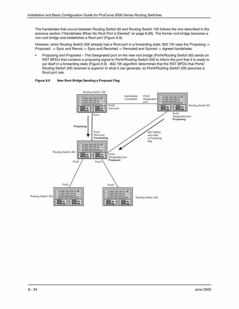
Installation and Basic Configuration Guide for ProCurve 9300 Series Routing Switches
The handshake that occurs between Routing Switch 60 and Routing Switch 100 follows the one described in the previous section (“Handshake When No Root Port is Elected” on page 8-28). The former root bridge becomes a non-root bridge and establishes a Root port (Figure 8.9).
However, since Routing Switch 200 already had a Root port in a forwarding state, 802.1W uses the Proposing -> Proposed -> Sync and Reroot -> Sync and Rerooted -> Rerooted and Synced -> Agreed handshake:
• Proposing and Proposed – The Designated port on the new root bridge (Port4/Routing Switch 60) sends an RST BPDU that contains a proposing signal to Port4/Routing Switch 200 to inform the port that it is ready to put itself in a forwarding state (Figure 8.9). 802.1W algorithm determines that the RST BPDU that Port4/Routing Switch 200 received is superior to what it can generate, so Port4/Routing Switch 200 assumes a Root port role.
Figure 8.9 New Root Bridge Sending a Proposal Flag
Routing Switch 100
Routing Switch 200
Routing Switch 400Routing Switch 300
Port1
Port1Root portForwarding
Port2
Port2 Port3
Port3
Routing Switch 60
Port4Designated portProposing
Port2Designatedport
Port2Root port
Port4Designated portProposed
HandshakeCompleted
RST BPDUsent witha Proposingflag
Proposing
8 - 34 June 2005

Configuring Spanning Tree Protocol (STP) and Advanced STP Features
• Sync and Reroot – The Root port then asserts a sync and a reroot signal on all the ports on the bridge. The signal tells the ports that a new Root port has been assigned and they are to renegotiate their new roles and states. The other ports on the bridge assert their sync and reroot signals. Information about the old Root port is discarded from all ports. Designated ports change into discarding states (Figure 8.10).
Figure 8.10 Sync and Reroot
Routing Switch 100
Routing Switch 200
Routing Switch 400Routing Switch 300
Port1
Port1Root portSyncRerootForwarding
Port2SyncRerootDiscarding
Port2 Port3
Port3SyncRerootDiscarding
Routing Switch 60
Port4Designated portProposing
Port2Designatedport
Port2Root port
Port4Root portSyncRerootDiscarding
Indicates a signal
Proposing
June 2005 8 - 35
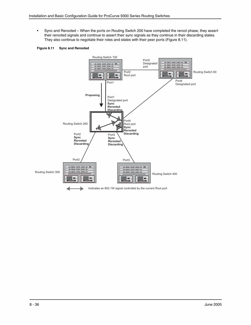
Installation and Basic Configuration Guide for ProCurve 9300 Series Routing Switches
• Sync and Rerooted – When the ports on Routing Switch 200 have completed the reroot phase, they assert their rerooted signals and continue to assert their sync signals as they continue in their discarding states. They also continue to negotiate their roles and states with their peer ports (Figure 8.11).
Figure 8.11 Sync and Rerooted
Routing Switch 100
Routing Switch 200
Routing Switch 400Routing Switch 300
Port1
Port1Designated portSyncRerootedDiscarding
Port2SyncRerootedDiscarding
Port2 Port3
Port3SyncRerootedDiscarding
Routing Switch 60
Port4Designated port
Port2Designatedport
Port2Root port
Port4Root portSyncRerootedDiscarding
Indicates an 802.1W signal controlled by the current Root port
Proposing
8 - 36 June 2005
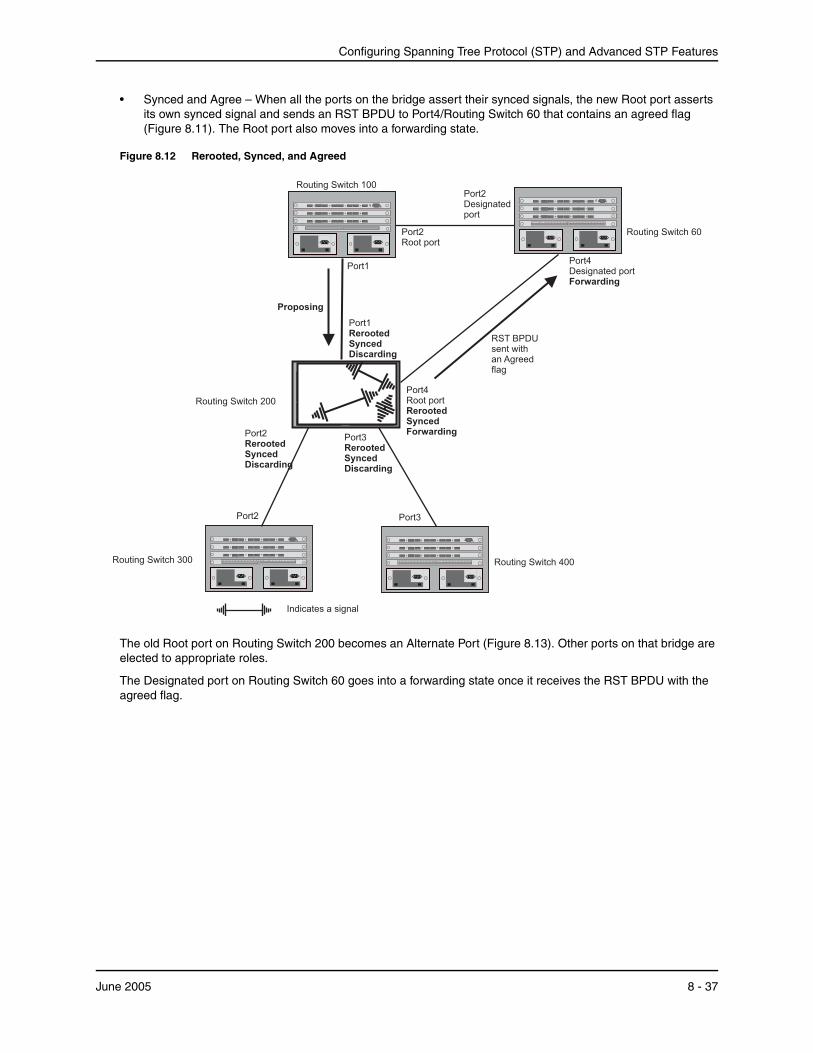
Configuring Spanning Tree Protocol (STP) and Advanced STP Features
• Synced and Agree – When all the ports on the bridge assert their synced signals, the new Root port asserts its own synced signal and sends an RST BPDU to Port4/Routing Switch 60 that contains an agreed flag (Figure 8.11). The Root port also moves into a forwarding state.
Figure 8.12 Rerooted, Synced, and Agreed
Routing Switch 100
Routing Switch 200
Routing Switch 400Routing Switch 300
Port1
Port1RerootedSyncedDiscarding
Port2RerootedSyncedDiscarding
Port2 Port3
Port3RerootedSyncedDiscarding
Routing Switch 60
Port4Designated portForwarding
Port2Designatedport
Port2Root port
Port4Root portRerootedSyncedForwarding
RST BPDUsent withan Agreedflag
Indicates a signal
Proposing
The old Root port on Routing Switch 200 becomes an Alternate Port (Figure 8.13). Other ports on that bridge are elected to appropriate roles.
The Designated port on Routing Switch 60 goes into a forwarding state once it receives the RST BPDU with the agreed flag.
June 2005 8 - 37

Installation and Basic Configuration Guide for ProCurve 9300 Series Routing Switches
Figure 8.13 Handshake Completed After Election of New Root Port
Routing Switch 100
Routing Switch 200
Routing Switch 400Routing Switch 300
Port1
Port1Alternate port
Port2
Port2 Port3
Port3
Routing Switch 60
Port4Designated port
Port2Designatedport
Port2Root port
Port4Root port
Proposing
Proposing
Port2
Proposing
Recall that Routing Switch 200 sent the agreed flag to Port4/Routing Switch 60 and not to Port1/Routing Switch 100 (the port that connects Routing Switch 100 to Routing Switch 200). Therefore, Port1/Routing Switch 100 does not go into forwarding state instantly. It waits until two instances of the forward delay timer expires on the port before it goes into forwarding state.
At this point the handshake between the Routing Switch 60 and Routing Switch 200 is complete.
The remaining bridges (Routing Switch 300 and Routing Switch 400) may have to go through the reroot handshake if a new Root port needs to be assigned.
8 - 38 June 2005
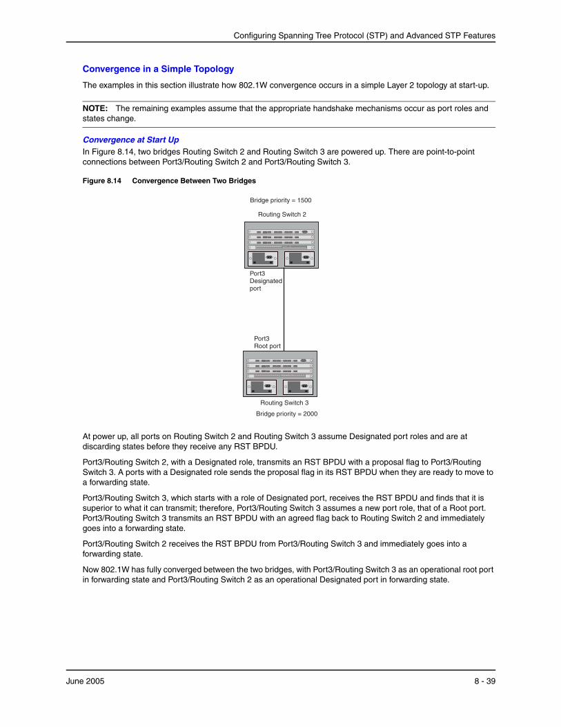
Configuring Spanning Tree Protocol (STP) and Advanced STP Features
Convergence in a Simple Topology
The examples in this section illustrate how 802.1W convergence occurs in a simple Layer 2 topology at start-up.
NOTE: The remaining examples assume that the appropriate handshake mechanisms occur as port roles and states change.
Convergence at Start UpIn Figure 8.14, two bridges Routing Switch 2 and Routing Switch 3 are powered up. There are point-to-point connections between Port3/Routing Switch 2 and Port3/Routing Switch 3.
Figure 8.14 Convergence Between Two Bridges
Port3Designatedport
Port3Root port
Bridge priority = 2000
Bridge priority = 1500
Routing Switch 2
Routing Switch 3
At power up, all ports on Routing Switch 2 and Routing Switch 3 assume Designated port roles and are at discarding states before they receive any RST BPDU.
Port3/Routing Switch 2, with a Designated role, transmits an RST BPDU with a proposal flag to Port3/Routing Switch 3. A ports with a Designated role sends the proposal flag in its RST BPDU when they are ready to move to a forwarding state.
Port3/Routing Switch 3, which starts with a role of Designated port, receives the RST BPDU and finds that it is superior to what it can transmit; therefore, Port3/Routing Switch 3 assumes a new port role, that of a Root port. Port3/Routing Switch 3 transmits an RST BPDU with an agreed flag back to Routing Switch 2 and immediately goes into a forwarding state.
Port3/Routing Switch 2 receives the RST BPDU from Port3/Routing Switch 3 and immediately goes into a forwarding state.
Now 802.1W has fully converged between the two bridges, with Port3/Routing Switch 3 as an operational root port in forwarding state and Port3/Routing Switch 2 as an operational Designated port in forwarding state.
June 2005 8 - 39
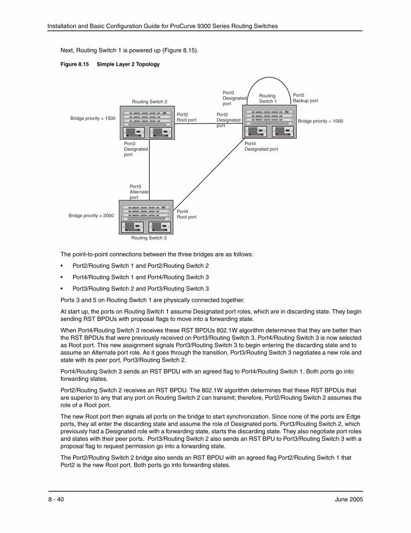
Installation and Basic Configuration Guide for ProCurve 9300 Series Routing Switches
Next, Routing Switch 1 is powered up (Figure 8.15).
Figure 8.15 Simple Layer 2 Topology
Port2Root port
Port2Designatedport
Port3Designatedport
Port5Backup port
Port4Designated port
Port3Designatedport
Port3Alternateport
Port4Root port
Bridge priority = 1000
Bridge priority = 2000
Bridge priority = 1500
Routing1SwitchRouting Switch 2
Routing 3Switch
The point-to-point connections between the three bridges are as follows:
• Port2/Routing Switch 1 and Port2/Routing Switch 2
• Port4/Routing Switch 1 and Port4/Routing Switch 3
• Port3/Routing Switch 2 and Port3/Routing Switch 3
Ports 3 and 5 on Routing Switch 1 are physically connected together.
At start up, the ports on Routing Switch 1 assume Designated port roles, which are in discarding state. They begin sending RST BPDUs with proposal flags to move into a forwarding state.
When Port4/Routing Switch 3 receives these RST BPDUs 802.1W algorithm determines that they are better than the RST BPDUs that were previously received on Port3/Routing Switch 3. Port4/Routing Switch 3 is now selected as Root port. This new assignment signals Port3/Routing Switch 3 to begin entering the discarding state and to assume an Alternate port role. As it goes through the transition, Port3/Routing Switch 3 negotiates a new role and state with its peer port, Port3/Routing Switch 2.
Port4/Routing Switch 3 sends an RST BPDU with an agreed flag to Port4/Routing Switch 1. Both ports go into forwarding states.
Port2/Routing Switch 2 receives an RST BPDU. The 802.1W algorithm determines that these RST BPDUs that are superior to any that any port on Routing Switch 2 can transmit; therefore, Port2/Routing Switch 2 assumes the role of a Root port.
The new Root port then signals all ports on the bridge to start synchronization. Since none of the ports are Edge ports, they all enter the discarding state and assume the role of Designated ports. Port3/Routing Switch 2, which previously had a Designated role with a forwarding state, starts the discarding state. They also negotiate port roles and states with their peer ports. Port3/Routing Switch 2 also sends an RST BPU to Port3/Routing Switch 3 with a proposal flag to request permission go into a forwarding state.
The Port2/Routing Switch 2 bridge also sends an RST BPDU with an agreed flag Port2/Routing Switch 1 that Port2 is the new Root port. Both ports go into forwarding states.
8 - 40 June 2005

Configuring Spanning Tree Protocol (STP) and Advanced STP Features
Now, Port3/Routing Switch 3 is currently in a discarding state and is negotiating a port role. It received RST BPDUs from Port3/Routing Switch 2. The 802.1W algorithm determines that the RST BPDUs Port3/Routing Switch 3 received are superior to those it can transmit; however, they are not superior to those that are currently being received by the current Root port (Port4). Therefore, Port3 retains the role of Alternate port.
Ports 3/Routing Switch 1 and Port5/Routing Switch 1 are physically connected. Port5/Routing Switch 1 received RST BPDUs that are superior to those received on Port3/Routing Switch 1; therefore, Port5/Routing Switch 1 is given the Backup port role while Port3 is given the Designated port role. Port3/Routing Switch 1, does not go directly into a forwarding state. It waits until the forward delay time expires twice on that port before it can proceed to the forwarding state.
Once convergence is achieved, the active Layer 2 forwarding path converges as shown in Figure 8.16.
Figure 8.16 Active Layer 2 Path
Port2 Port2
Port7 Port8
Port3
Port3
Port4Port4
Port3
Port2 Port3
Routing Switch 2Bridge priority = 200
Routing Switch 4Bridge priority = 400
Routing Switch 3Bridge priority = 300
Routing Switch 1Bridge priority = 1000
Port4
Port5
Port3
Port3
Routing Switch 6Bridge priority = 900
Routing Switch 5Bridge priority = 60
Port2
Port5 Port5
Port4
Indicates the active Layer 2 path
June 2005 8 - 41

Installation and Basic Configuration Guide for ProCurve 9300 Series Routing Switches
Convergence After a Link Failure
What happens if a link in the 802.1W topology fails?
For example, Port2/Routing Switch , which is the port that connects Routing Switch 2 to the root bridge (Routing Switch 1), fails. Both Routing Switch 2 and Routing Switch 1 notice the topology change (Figure 8.17).
Figure 8.17 Link Failure in the Topology
Port2Port2
Port3 Port5
Port4Port3
Port3 Port4
Bridge priority = 1000
Bridge priority = 2000
Bridge priority = 1500
RoutingSwitch 1Routing 2Switch
Routing Switch 3
Routing Switch 1 sets its Port2 into a discarding state.
At the same time, Routing Switch 2 assumes the role of a root bridge since its root port failed and it has no operational Alternate port. Port3/Routing Switch 2, which currently has a Designated port role, sends an RST BPDU to Routing Switch 3. The RST BPDU contains a proposal flag and a bridge ID of Routing Switch 2 as its root bridge ID.
When Port3/Routing Switch 3 receives the RST BPDUs, 802.1W algorithm determines that they are inferior to those that the port can transmit. Therefore, Port3/Routing Switch 3 is given a new role, that of a Designated port. Port3/Routing Switch 3 then sends an RST BPDU with a proposal flag to Routing Switch 2, along with the new role information. However, the root bridge ID transmitted in the RST BPDU is still Routing Switch 1.
When Port3/Routing Switch 2 receives the RST BPDU, 802.1W algorithm determines that it is superior to the RST BPDU that it can transmit; therefore, Port3/Routing Switch 2 receives a new role; that of a Root port. Port3/Routing Switch 2 then sends an RST BPDU with an agreed flag to Port3/Routing Switch 3. Port3/Routing Switch 2 goes into a forwarding state.
When Port3/Routing Switch 3 receives the RST BPDU that Port3/Routing Switch 2 sent, Port3/Routing Switch 3 changes into a forwarding state, which then completes the full convergence of the topology.
Convergence at Link Restoration
When Port2/Routing Switch 2 is restored, both Routing Switch 2 and Routing Switch 1 recognize the change. Port2/Routing Switch 1 starts assuming the role of a Designated port and sends an RST BPDU containing a proposal flag to Port2/Routing Switch 2.
When Port2/Routing Switch 2 receives the RST BPDUs, 802.1W algorithm determines that the RST BPDUs the port received are better than those received on Port3/Routing Switch 3; therefore, Port2/Routing Switch 2 is given the role of a Root port. All the ports on Routing Switch 2 are informed that a new Root port has been assigned which then signals all the ports to synchronize their roles and states. Port3/Routing Switch 2, which was the
8 - 42 June 2005
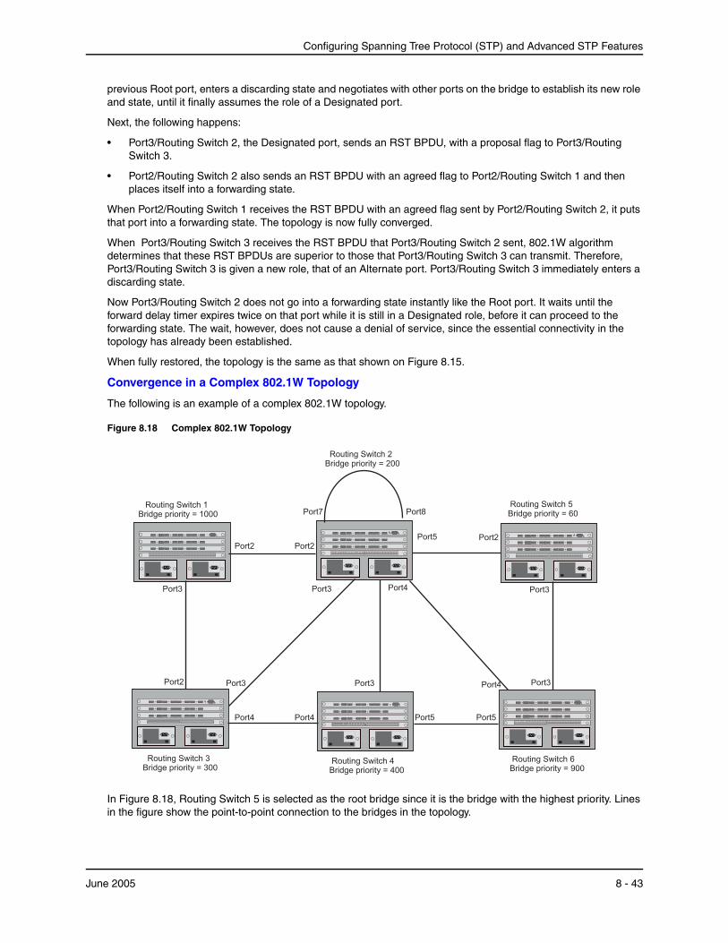
Configuring Spanning Tree Protocol (STP) and Advanced STP Features
previous Root port, enters a discarding state and negotiates with other ports on the bridge to establish its new role and state, until it finally assumes the role of a Designated port.
Next, the following happens:
• Port3/Routing Switch 2, the Designated port, sends an RST BPDU, with a proposal flag to Port3/Routing Switch 3.
• Port2/Routing Switch 2 also sends an RST BPDU with an agreed flag to Port2/Routing Switch 1 and then places itself into a forwarding state.
When Port2/Routing Switch 1 receives the RST BPDU with an agreed flag sent by Port2/Routing Switch 2, it puts that port into a forwarding state. The topology is now fully converged.
When Port3/Routing Switch 3 receives the RST BPDU that Port3/Routing Switch 2 sent, 802.1W algorithm determines that these RST BPDUs are superior to those that Port3/Routing Switch 3 can transmit. Therefore, Port3/Routing Switch 3 is given a new role, that of an Alternate port. Port3/Routing Switch 3 immediately enters a discarding state.
Now Port3/Routing Switch 2 does not go into a forwarding state instantly like the Root port. It waits until the forward delay timer expires twice on that port while it is still in a Designated role, before it can proceed to the forwarding state. The wait, however, does not cause a denial of service, since the essential connectivity in the topology has already been established.
When fully restored, the topology is the same as that shown on Figure 8.15.
Convergence in a Complex 802.1W Topology
The following is an example of a complex 802.1W topology.
Figure 8.18 Complex 802.1W Topology
Port2 Port2
Port7 Port8
Port3
Port3
Port4Port4
Port3
Port2 Port3
Routing 2Bridge priority = 200
Switch
Routing 4Bridge priority = 400
SwitchRouting 3Bridge priority = 300
Switch
Routing Switch 1Bridge priority = 1000
Port4
Port5
Port3
Port3
Routing 6Bridge priority = 900
Switch
Routing 5Bridge priority = 60
Switch
Port2
Port5 Port5
Port4
In Figure 8.18, Routing Switch 5 is selected as the root bridge since it is the bridge with the highest priority. Lines in the figure show the point-to-point connection to the bridges in the topology.
June 2005 8 - 43
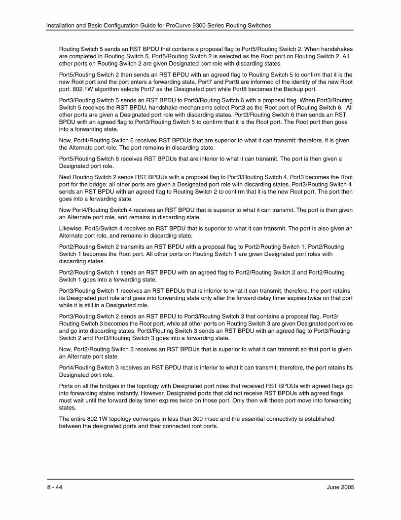
Installation and Basic Configuration Guide for ProCurve 9300 Series Routing Switches
Routing Switch 5 sends an RST BPDU that contains a proposal flag to Port5/Routing Switch 2. When handshakes are completed in Routing Switch 5, Port5/Routing Switch 2 is selected as the Root port on Routing Switch 2. All other ports on Routing Switch 2 are given Designated port role with discarding states.
Port5/Routing Switch 2 then sends an RST BPDU with an agreed flag to Routing Switch 5 to confirm that it is the new Root port and the port enters a forwarding state. Port7 and Port8 are informed of the identity of the new Root port. 802.1W algorithm selects Port7 as the Designated port while Port8 becomes the Backup port.
Port3/Routing Switch 5 sends an RST BPDU to Port3/Routing Switch 6 with a proposal flag. When Port3/Routing Switch 5 receives the RST BPDU, handshake mechanisms select Port3 as the Root port of Routing Switch 6. All other ports are given a Designated port role with discarding states. Port3/Routing Switch 6 then sends an RST BPDU with an agreed flag to Port3/Routing Switch 5 to confirm that it is the Root port. The Root port then goes into a forwarding state.
Now, Port4/Routing Switch 6 receives RST BPDUs that are superior to what it can transmit; therefore, it is given the Alternate port role. The port remains in discarding state.
Port5/Routing Switch 6 receives RST BPDUs that are inferior to what it can transmit. The port is then given a Designated port role.
Next Routing Switch 2 sends RST BPDUs with a proposal flag to Port3/Routing Switch 4. Port3 becomes the Root port for the bridge; all other ports are given a Designated port role with discarding states. Port3/Routing Switch 4 sends an RST BPDU with an agreed flag to Routing Switch 2 to confirm that it is the new Root port. The port then goes into a forwarding state.
Now Port4/Routing Switch 4 receives an RST BPDU that is superior to what it can transmit. The port is then given an Alternate port role, and remains in discarding state.
Likewise, Port5/Switch 4 receives an RST BPDU that is superior to what it can transmit. The port is also given an Alternate port role, and remains in discarding state.
Port2/Routing Switch 2 transmits an RST BPDU with a proposal flag to Port2/Routing Switch 1. Port2/Routing Switch 1 becomes the Root port. All other ports on Routing Switch 1 are given Designated port roles with discarding states.
Port2/Routing Switch 1 sends an RST BPDU with an agreed flag to Port2/Routing Switch 2 and Port2/Routing Switch 1 goes into a forwarding state.
Port3/Routing Switch 1 receives an RST BPDUs that is inferior to what it can transmit; therefore, the port retains its Designated port role and goes into forwarding state only after the forward delay timer expires twice on that port while it is still in a Designated role.
Port3/Routing Switch 2 sends an RST BPDU to Port3/Routing Switch 3 that contains a proposal flag. Port3/Routing Switch 3 becomes the Root port, while all other ports on Routing Switch 3 are given Designated port roles and go into discarding states. Port3/Routing Switch 3 sends an RST BPDU with an agreed flag to Port3/Routing Switch 2 and Port3/Routing Switch 3 goes into a forwarding state.
Now, Port2/Routing Switch 3 receives an RST BPDUs that is superior to what it can transmit so that port is given an Alternate port state.
Port4/Routing Switch 3 receives an RST BPDU that is inferior to what it can transmit; therefore, the port retains its Designated port role.
Ports on all the bridges in the topology with Designated port roles that received RST BPDUs with agreed flags go into forwarding states instantly. However, Designated ports that did not receive RST BPDUs with agreed flags must wait until the forward delay timer expires twice on those port. Only then will these port move into forwarding states.
The entire 802.1W topology converges in less than 300 msec and the essential connectivity is established between the designated ports and their connected root ports.
8 - 44 June 2005
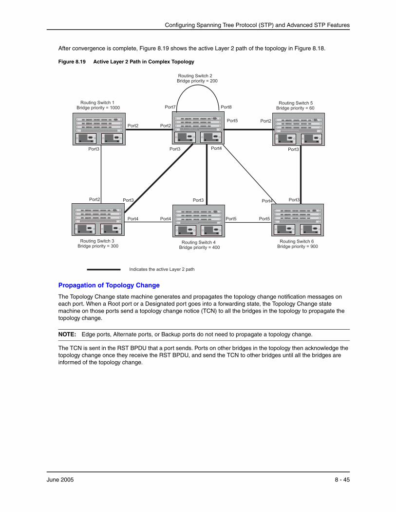
Configuring Spanning Tree Protocol (STP) and Advanced STP Features
After convergence is complete, Figure 8.19 shows the active Layer 2 path of the topology in Figure 8.18.
Figure 8.19 Active Layer 2 Path in Complex Topology
Port2 Port2
Port7 Port8
Port3
Port3
Port4Port4
Port3
Port2 Port3
Routing Switch 2Bridge priority = 200
Routing Switch 4Bridge priority = 400
Routing Switch 3Bridge priority = 300
Routing Switch 1Bridge priority = 1000
Port4
Port5
Port3
Port3
Routing Switch 6Bridge priority = 900
Routing Switch 5Bridge priority = 60
Port2
Port5 Port5
Port4
Indicates the active Layer 2 path
Propagation of Topology Change
The Topology Change state machine generates and propagates the topology change notification messages on each port. When a Root port or a Designated port goes into a forwarding state, the Topology Change state machine on those ports send a topology change notice (TCN) to all the bridges in the topology to propagate the topology change.
NOTE: Edge ports, Alternate ports, or Backup ports do not need to propagate a topology change.
The TCN is sent in the RST BPDU that a port sends. Ports on other bridges in the topology then acknowledge the topology change once they receive the RST BPDU, and send the TCN to other bridges until all the bridges are informed of the topology change.
June 2005 8 - 45
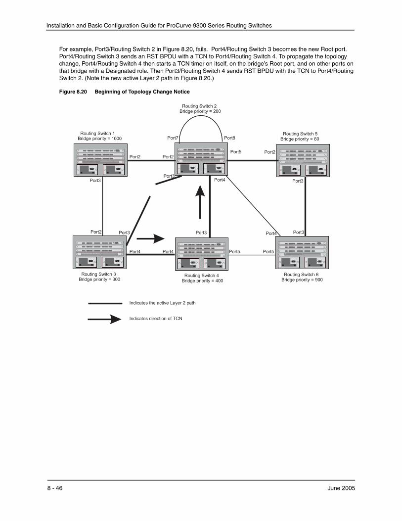
Installation and Basic Configuration Guide for ProCurve 9300 Series Routing Switches
For example, Port3/Routing Switch 2 in Figure 8.20, fails. Port4/Routing Switch 3 becomes the new Root port. Port4/Routing Switch 3 sends an RST BPDU with a TCN to Port4/Routing Switch 4. To propagate the topology change, Port4/Routing Switch 4 then starts a TCN timer on itself, on the bridge’s Root port, and on other ports on that bridge with a Designated role. Then Port3/Routing Switch 4 sends RST BPDU with the TCN to Port4/Routing Switch 2. (Note the new active Layer 2 path in Figure 8.20.)
Figure 8.20 Beginning of Topology Change Notice
Port2 Port2
Port7 Port8
Port3
Port3
Port4Port4
Port3
Port2 Port3
Routing Switch 2Bridge priority = 200
Routing Switch 4Bridge priority = 400
Routing Switch 3Bridge priority = 300
Routing Switch 1Bridge priority = 1000
Port4
Port5
Port3
Port3
Routing Switch 6Bridge priority = 900
Routing Switch 5Bridge priority = 60
Port2
Port5 Port5
Port4
Indicates the active Layer 2 path
Indicates direction of TCN
8 - 46 June 2005

Configuring Spanning Tree Protocol (STP) and Advanced STP Features
Routing Switch 2 then starts the TCN timer on the Designated ports and sends RST BPDUs that contain the TCN as follows (Figure 8.21):
• Port5/Routing Switch 2 sends the TCN to Port2/Routing Switch 5
• Port4/Routing Switch 2 sends the TCN to Port4/Routing Switch 6
• Port2/Routing Switch 2 sends the TCN to Port2/Routing Switch 1
Figure 8.21 Sending TCN to Bridges Connected to Routing Switch 2
Port2 Port2
Port7 Port8
Port3
Port3
Port4Port4
Port3
Port2 Port3
Routing 2Bridge priority = 200
Switch
Routing 4Bridge priority = 400
SwitchRouting Switch 3Bridge priority = 300
Routing 1Bridge priority = 1000
Switch
Port4
Port5
Port3
Port3
Routing 6Bridge priority = 900
Switch
Routing 5Bridge priority = 60
Switch
Port2
Port5 Port5
Port4
Indicates the active Layer 2 path
Indicates direction of TCN
June 2005 8 - 47
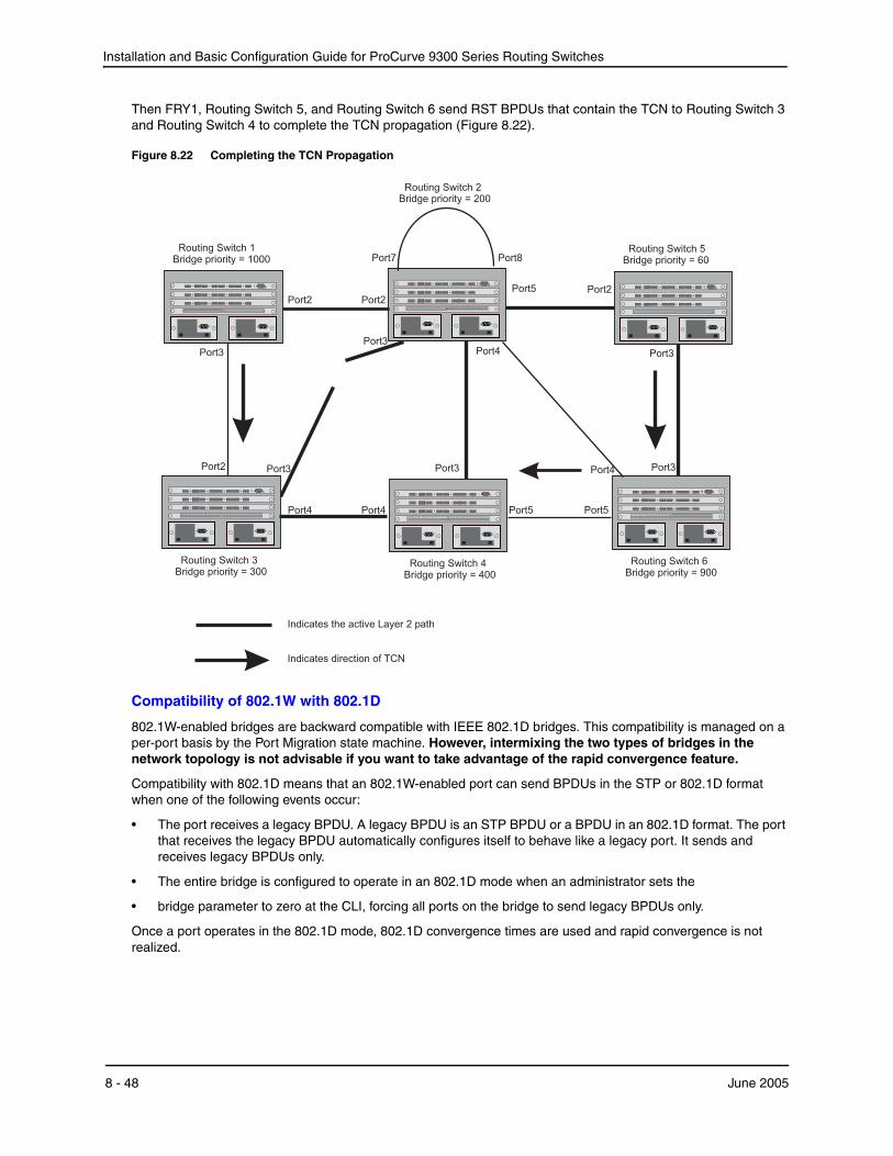
Installation and Basic Configuration Guide for ProCurve 9300 Series Routing Switches
Then FRY1, Routing Switch 5, and Routing Switch 6 send RST BPDUs that contain the TCN to Routing Switch 3 and Routing Switch 4 to complete the TCN propagation (Figure 8.22).
Figure 8.22 Completing the TCN Propagation
Port2 Port2
Port7 Port8
Port3
Port3
Port4Port4
Port3
Port2 Port3
Routing 2Bridge priority = 200
Switch
Routing 4Bridge priority = 400
SwitchRouting Switch 3Bridge priority = 300
Routing S 1Bridge priority = 1000
witch
Port4
Port5
Port3
Port3
Routing 6Bridge priority = 900
Switch
Routing S 5Bridge priority = 60
witch
Port2
Port5 Port5
Port4
Indicates the active Layer 2 path
Indicates direction of TCN
Compatibility of 802.1W with 802.1D
802.1W-enabled bridges are backward compatible with IEEE 802.1D bridges. This compatibility is managed on a per-port basis by the Port Migration state machine. However, intermixing the two types of bridges in the network topology is not advisable if you want to take advantage of the rapid convergence feature.
Compatibility with 802.1D means that an 802.1W-enabled port can send BPDUs in the STP or 802.1D format when one of the following events occur:
• The port receives a legacy BPDU. A legacy BPDU is an STP BPDU or a BPDU in an 802.1D format. The port that receives the legacy BPDU automatically configures itself to behave like a legacy port. It sends and receives legacy BPDUs only.
• The entire bridge is configured to operate in an 802.1D mode when an administrator sets the
• bridge parameter to zero at the CLI, forcing all ports on the bridge to send legacy BPDUs only.
Once a port operates in the 802.1D mode, 802.1D convergence times are used and rapid convergence is not realized.
8 - 48 June 2005
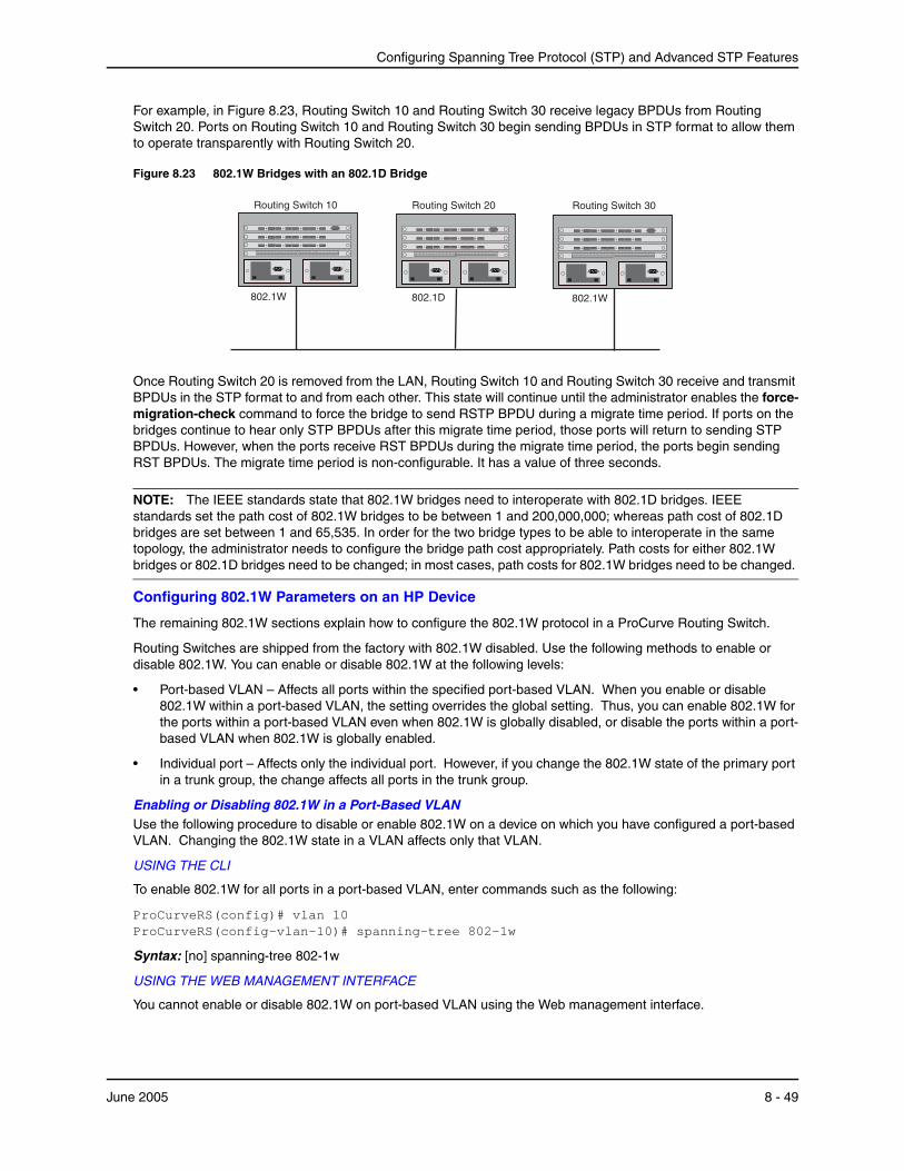
Configuring Spanning Tree Protocol (STP) and Advanced STP Features
For example, in Figure 8.23, Routing Switch 10 and Routing Switch 30 receive legacy BPDUs from Routing Switch 20. Ports on Routing Switch 10 and Routing Switch 30 begin sending BPDUs in STP format to allow them to operate transparently with Routing Switch 20.
Figure 8.23 802.1W Bridges with an 802.1D Bridge
Routing Switch 10 Routing 20Switch Routing 30Switch
802.1W 802.1W802.1D
Once Routing Switch 20 is removed from the LAN, Routing Switch 10 and Routing Switch 30 receive and transmit BPDUs in the STP format to and from each other. This state will continue until the administrator enables the force-migration-check command to force the bridge to send RSTP BPDU during a migrate time period. If ports on the bridges continue to hear only STP BPDUs after this migrate time period, those ports will return to sending STP BPDUs. However, when the ports receive RST BPDUs during the migrate time period, the ports begin sending RST BPDUs. The migrate time period is non-configurable. It has a value of three seconds.
NOTE: The IEEE standards state that 802.1W bridges need to interoperate with 802.1D bridges. IEEE standards set the path cost of 802.1W bridges to be between 1 and 200,000,000; whereas path cost of 802.1D bridges are set between 1 and 65,535. In order for the two bridge types to be able to interoperate in the same topology, the administrator needs to configure the bridge path cost appropriately. Path costs for either 802.1W bridges or 802.1D bridges need to be changed; in most cases, path costs for 802.1W bridges need to be changed.
Configuring 802.1W Parameters on an HP Device
The remaining 802.1W sections explain how to configure the 802.1W protocol in a ProCurve Routing Switch.
Routing Switches are shipped from the factory with 802.1W disabled. Use the following methods to enable or disable 802.1W. You can enable or disable 802.1W at the following levels:
• Port-based VLAN – Affects all ports within the specified port-based VLAN. When you enable or disable 802.1W within a port-based VLAN, the setting overrides the global setting. Thus, you can enable 802.1W for the ports within a port-based VLAN even when 802.1W is globally disabled, or disable the ports within a port-based VLAN when 802.1W is globally enabled.
• Individual port – Affects only the individual port. However, if you change the 802.1W state of the primary port in a trunk group, the change affects all ports in the trunk group.
Enabling or Disabling 802.1W in a Port-Based VLAN Use the following procedure to disable or enable 802.1W on a device on which you have configured a port-based VLAN. Changing the 802.1W state in a VLAN affects only that VLAN.
USING THE CLI
To enable 802.1W for all ports in a port-based VLAN, enter commands such as the following:
ProCurveRS(config)# vlan 10 ProCurveRS(config-vlan-10)# spanning-tree 802-1w
Syntax: [no] spanning-tree 802-1w
USING THE WEB MANAGEMENT INTERFACE
You cannot enable or disable 802.1W on port-based VLAN using the Web management interface.
June 2005 8 - 49
Installation and Basic Configuration Guide for ProCurve 9300 Series Routing Switches
Enabling or Disabling 802.1W on a Single Spanning TreeTo enable 802.1W for all ports of a single spanning tree, use the procedure in this section.
USING THE CLI
Enter a command such as the following:
ProCurveRS(config-vlan-10)# spanning-tree single 802-1w
Syntax: [no] spanning-tree single 802-1w
USING THE WEB MANAGEMENT INTERFACE
You cannot enable or disable 802.1W on a single spanning tree using the Web management interface.
Disabling or Enabling 802.1W on an Individual PortThe spanning-tree 802-1w or spanning-tree single 802-1w command must be used to initially enable 802.1W on ports. Both commands enable 802.1W on all ports that belong to the VLAN or to the single spanning tree.
Once 802.1W is enabled on a port, it can be disabled on individual ports. 802.1W that have been disabled on individual ports can then be enabled as required.
NOTE: If you change the 802.1W state of the primary port in a trunk group, the change affects all ports in that trunk group.
USING THE CLI
To disable or enable 802.1W on an individual port, enter commands such as the following:
ProCurveRS(config)# interface 1/1 ProCurveRS(config-if-1/1)# no spanning-tree
Syntax: [no] spanning-tree
USING THE WEB MANAGEMENT INTERFACE
You cannot enable or disable 802.1W on individual ports using the Web management interface.
Changing 802.1W Bridge ParametersWhen you make changes to 802.1W bridge parameters, the changes are applied to individual ports on the bridge. To change 802.1W bridge parameters, use the following methods.
USING THE CLI
To designate a priority for a bridge, enter a command such as the following:
ProCurveRS(config)# spanning-tree 802-1w priority 10
The command in this example changes the priority on a device on which you have not configured port-based VLANs. The change applies to the default VLAN. If you have configured a port-based VLAN on the device, you can configure the parameters only at the configuration level for individual VLANs. Enter commands such as the following:
ProCurveRS(config)# vlan 20 ProCurveRS(config-vlan-20)# spanning-tree 802-1w priority 0
To make this change in the default VLAN, enter the following commands:
ProCurveRS(config)# vlan 1 ProCurveRS(config-vlan-1)# spanning-tree 802-1w priority 0
Syntax: spanning-tree 802-1w [forward-delay <value>] | [hello-time <value>] | [max-age <time>] | [force-version <value>] | [priority <value>]
The forward-delay <value> parameter specifies how long a port waits before it forwards an RST BPDU after a topology change. This can be a value from 4 – 30 seconds. The default is 15 seconds.
8 - 50 June 2005
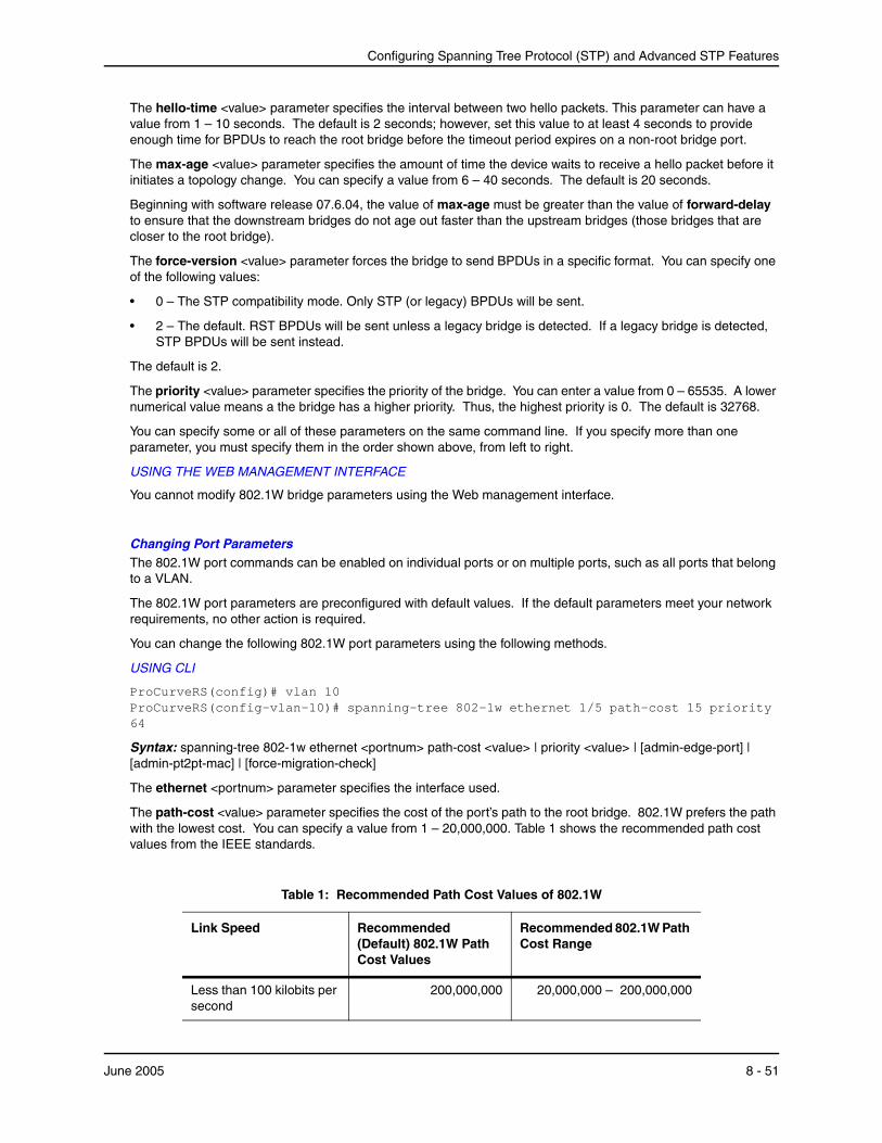
Configuring Spanning Tree Protocol (STP) and Advanced STP Features
The hello-time <value> parameter specifies the interval between two hello packets. This parameter can have a value from 1 – 10 seconds. The default is 2 seconds; however, set this value to at least 4 seconds to provide enough time for BPDUs to reach the root bridge before the timeout period expires on a non-root bridge port.
The max-age <value> parameter specifies the amount of time the device waits to receive a hello packet before it initiates a topology change. You can specify a value from 6 – 40 seconds. The default is 20 seconds.
Beginning with software release 07.6.04, the value of max-age must be greater than the value of forward-delay to ensure that the downstream bridges do not age out faster than the upstream bridges (those bridges that are closer to the root bridge).
The force-version <value> parameter forces the bridge to send BPDUs in a specific format. You can specify one of the following values:
• 0 – The STP compatibility mode. Only STP (or legacy) BPDUs will be sent.
• 2 – The default. RST BPDUs will be sent unless a legacy bridge is detected. If a legacy bridge is detected, STP BPDUs will be sent instead.
The default is 2.
The priority <value> parameter specifies the priority of the bridge. You can enter a value from 0 – 65535. A lower numerical value means a the bridge has a higher priority. Thus, the highest priority is 0. The default is 32768.
You can specify some or all of these parameters on the same command line. If you specify more than one parameter, you must specify them in the order shown above, from left to right.
USING THE WEB MANAGEMENT INTERFACE
You cannot modify 802.1W bridge parameters using the Web management interface.
Changing Port Parameters The 802.1W port commands can be enabled on individual ports or on multiple ports, such as all ports that belong to a VLAN.
The 802.1W port parameters are preconfigured with default values. If the default parameters meet your network requirements, no other action is required.
You can change the following 802.1W port parameters using the following methods.
USING CLI
ProCurveRS(config)# vlan 10 ProCurveRS(config-vlan-10)# spanning-tree 802-1w ethernet 1/5 path-cost 15 priority 64
Syntax: spanning-tree 802-1w ethernet <portnum> path-cost <value> | priority <value> | [admin-edge-port] | [admin-pt2pt-mac] | [force-migration-check]
The ethernet <portnum> parameter specifies the interface used.
The path-cost <value> parameter specifies the cost of the port’s path to the root bridge. 802.1W prefers the path with the lowest cost. You can specify a value from 1 – 20,000,000. Table 1 shows the recommended path cost values from the IEEE standards.
Table 1: Recommended Path Cost Values of 802.1W
Link Speed Recommended (Default) 802.1W Path Cost Values
Recommended 802.1W Path Cost Range
Less than 100 kilobits per second
200,000,000 20,000,000 – 200,000,000
June 2005 8 - 51
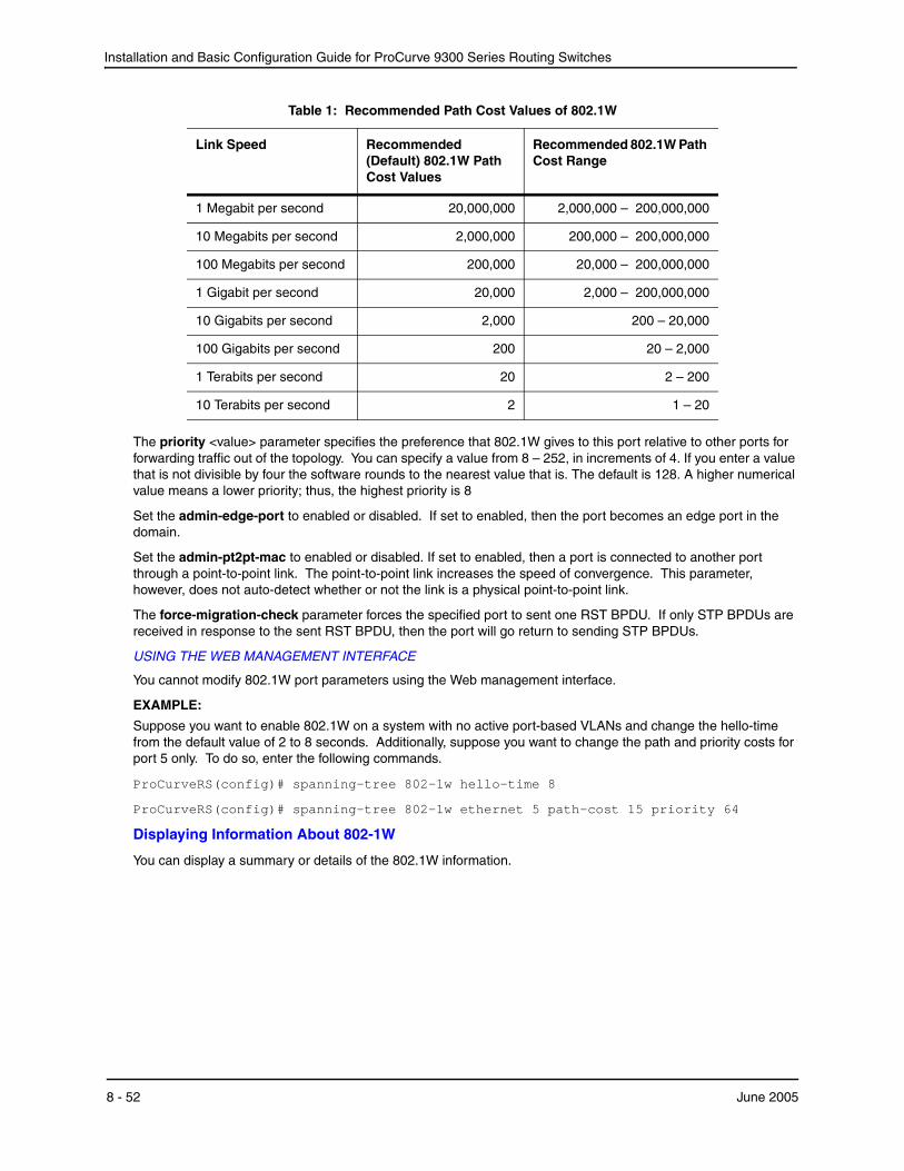
Installation and Basic Configuration Guide for ProCurve 9300 Series Routing Switches
The priority <value> parameter specifies the preference that 802.1W gives to this port relative to other ports for forwarding traffic out of the topology. You can specify a value from 8 – 252, in increments of 4. If you enter a value that is not divisible by four the software rounds to the nearest value that is. The default is 128. A higher numerical value means a lower priority; thus, the highest priority is 8
Set the admin-edge-port to enabled or disabled. If set to enabled, then the port becomes an edge port in the domain.
Set the admin-pt2pt-mac to enabled or disabled. If set to enabled, then a port is connected to another port through a point-to-point link. The point-to-point link increases the speed of convergence. This parameter, however, does not auto-detect whether or not the link is a physical point-to-point link.
The force-migration-check parameter forces the specified port to sent one RST BPDU. If only STP BPDUs are received in response to the sent RST BPDU, then the port will go return to sending STP BPDUs.
USING THE WEB MANAGEMENT INTERFACE
You cannot modify 802.1W port parameters using the Web management interface.
EXAMPLE:
Suppose you want to enable 802.1W on a system with no active port-based VLANs and change the hello-time from the default value of 2 to 8 seconds. Additionally, suppose you want to change the path and priority costs for port 5 only. To do so, enter the following commands.
ProCurveRS(config)# spanning-tree 802-1w hello-time 8
ProCurveRS(config)# spanning-tree 802-1w ethernet 5 path-cost 15 priority 64
Displaying Information About 802-1W
You can display a summary or details of the 802.1W information.
1 Megabit per second 20,000,000 2,000,000 – 200,000,000
10 Megabits per second 2,000,000 200,000 – 200,000,000
100 Megabits per second 200,000 20,000 – 200,000,000
1 Gigabit per second 20,000 2,000 – 200,000,000
10 Gigabits per second 2,000 200 – 20,000
100 Gigabits per second 200 20 – 2,000
1 Terabits per second 20 2 – 200
10 Terabits per second 2 1 – 20
Table 1: Recommended Path Cost Values of 802.1W
Link Speed Recommended (Default) 802.1W Path Cost Values
Recommended 802.1W Path Cost Range
8 - 52 June 2005
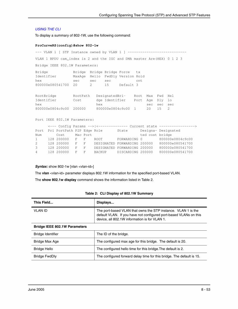
Configuring Spanning Tree Protocol (STP) and Advanced STP Features
USING THE CLI
To display a summary of 802-1W, use the following command:
ProCurveRS(config)#show 802-1w
--- VLAN 1 [ STP Instance owned by VLAN 1 ] ----------------------------
VLAN 1 BPDU cam_index is 2 and the IGC and DMA master Are(HEX) 0 1 2 3
Bridge IEEE 802.1W Parameters:
Bridge Bridge Bridge Bridge Force tx Identifier MaxAge Hello FwdDly Version Hold hex sec sec sec cnt 800000e080541700 20 2 15 Default 3
RootBridge RootPath DesignatedBri- Root Max Fwd Hel Identifier Cost dge Identifier Port Age Dly lo hex hex sec sec sec 800000e0804c9c00 200000 800000e0804c9c00 1 20 15 2
Port IEEE 802.1W Parameters:
<--- Config Params -->|<-------------- Current state -----------------> Port Pri PortPath P2P Edge Role State Designa- Designated Num Cost Mac Port ted cost bridge 1 128 200000 F F ROOT FORWARDING 0 800000e0804c9c00 2 128 200000 F F DESIGNATED FORWARDING 200000 800000e080541700 3 128 200000 F F DESIGNATED FORWARDING 200000 800000e080541700 4 128 200000 F F BACKUP DISCARDING 200000 800000e080541700
Syntax: show 802-1w [vlan <vlan-id>]
The vlan <vlan-id> parameter displays 802.1W information for the specified port-based VLAN.
The show 802.1w display command shows the information listed in Table 2.
Table 2: CLI Display of 802.1W Summary
This Field... Displays...
VLAN ID The port-based VLAN that owns the STP instance. VLAN 1 is the default VLAN. If you have not configured port-based VLANs on this device, all 802.1W information is for VLAN 1.
Bridge IEEE 802.1W Parameters
Bridge Identifier The ID of the bridge.
Bridge Max Age The configured max age for this bridge. The default is 20.
Bridge Hello The configured hello time for this bridge.The default is 2.
Bridge FwdDly The configured forward delay time for this bridge. The default is 15.
June 2005 8 - 53
Installation and Basic Configuration Guide for ProCurve 9300 Series Routing Switches
Force-Version The configured force version value. One of the following value is displayed:
• 0 – The bridge has been forced to operate in an STP compatibility mode.
• 2 – The bridge has been forced to operate in an 802.1W mode. (This is the default.)
txHoldCnt The number of BPDUs that can be transmitted per Hello Interval. The default is 3.
Root Bridge Identifier ID of the Root bridge that is associated with this bridge
Root Path Cost The cost to reach the root bridge from this bridge. If the bridge is the root bridge, then this parameter shows a value of zero.
Designated Bridge Identifier The bridge from where the root information was received.It can be from the root bridge itself, but it could also be from another bridge.
Root Port The port on which the root information was received. This is the port that is connected to the Designated Bridge.
Max Age The max age is derived from the Root port. An 802.1W-enabled bridge uses this value, along with the hello and message age parameters to compute the effective age of an RST BPDU.
The message age parameter is generated by the Designated port and transmitted in the RST BPDU. RST BPDUs transmitted by a Designated port of the root bridge contains a message value of zero.
Effective age is the amount of time the Root port, Alternate port, or Backup port retains the information it received from its peer Designated port. Effective age is reset every time a port receives an RST BPDU from its Designated port. If a Root port does not receive an RST BPDU from its peer Designated port for a duration more than the effective age, the Root port ages out the existing information and recomputes the topology.
If the port is operating in 802.1D compatible mode, then max age functionality is the same as in 802.1D (STP).
Fwd Dly The number of seconds a non-edge Designated port waits until it can apply any of the following transitions, if the RST BPDU it receives does not have an agreed flag:
• Discarding state to learning state
• Learning state to forwarding state
When a non-edge port receives the RST BPDU it goes into forwarding state within 4 seconds or after two hello timers expire on the port.
Fwd Dly is also the number of seconds that a Root port waits for an RST BPDU with a proposal flag before it applies the state transitions listed above.
If the port is operating in 802.1D compatible mode, then forward delay functionality is the same as in 802.1D (STP).
Table 2: CLI Display of 802.1W Summary (Continued)
This Field... Displays...
8 - 54 June 2005
Configuring Spanning Tree Protocol (STP) and Advanced STP Features
Hello The hello value derived from the Root port. It is the number of seconds between two Hello packets.
Port IEEE 802.1W Parameters
Port Num The port number shown in a slot#/port# format.
Pri The configured priority of the port. The default is 128 or 0x80.
Port Path Cost The configured path cost on a link connected to this port.
P2P Mac Indicates if the point-to-point-mac parameter is configured to be a point-to-point link:
• T – The link is configured as a point-to-point link.
• F – The link is not configured as a point-to-point link. This is the default.
Edge port Indicates if the port is configured as an operational Edge port:
• T – The port is configured as an Edge port.
• F – The port is not configured as an Edge port. This is the default.
Role The current role of the port:
• Root
• Designated
• Alternate
• Backup
• Disabled
Refer to “Bridges and Bridge Port Roles” on page 8-23 for definitions of the roles.
State The port’s current 802.1W state. A port can have one of the following states:
• Forwarding
• Discarding
• Learning
• Disabled
Refer to “Bridge Port States” on page 8-27 and “Edge Port and Non-Edge Port States” on page 8-27.
Designated Cost The best root path cost that this port received, including the best root path cost that it can transmit.
Designated Bridge The ID of the bridge that sent the best RST BPDU that was received on this port.
Table 2: CLI Display of 802.1W Summary (Continued)
This Field... Displays...
June 2005 8 - 55
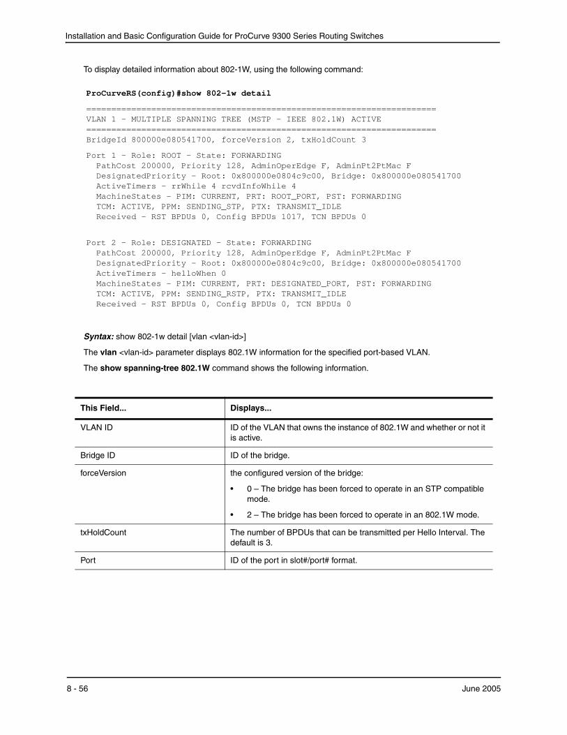
Installation and Basic Configuration Guide for ProCurve 9300 Series Routing Switches
To display detailed information about 802-1W, using the following command:
ProCurveRS(config)#show 802-1w detail
====================================================================== VLAN 1 - MULTIPLE SPANNING TREE (MSTP - IEEE 802.1W) ACTIVE ====================================================================== BridgeId 800000e080541700, forceVersion 2, txHoldCount 3
Port 1 - Role: ROOT - State: FORWARDING PathCost 200000, Priority 128, AdminOperEdge F, AdminPt2PtMac F DesignatedPriority - Root: 0x800000e0804c9c00, Bridge: 0x800000e080541700 ActiveTimers - rrWhile 4 rcvdInfoWhile 4 MachineStates - PIM: CURRENT, PRT: ROOT_PORT, PST: FORWARDING TCM: ACTIVE, PPM: SENDING_STP, PTX: TRANSMIT_IDLE Received - RST BPDUs 0, Config BPDUs 1017, TCN BPDUs 0
Port 2 - Role: DESIGNATED - State: FORWARDING PathCost 200000, Priority 128, AdminOperEdge F, AdminPt2PtMac F DesignatedPriority - Root: 0x800000e0804c9c00, Bridge: 0x800000e080541700 ActiveTimers - helloWhen 0 MachineStates - PIM: CURRENT, PRT: DESIGNATED_PORT, PST: FORWARDING TCM: ACTIVE, PPM: SENDING_RSTP, PTX: TRANSMIT_IDLE Received - RST BPDUs 0, Config BPDUs 0, TCN BPDUs 0
Syntax: show 802-1w detail [vlan <vlan-id>]
The vlan <vlan-id> parameter displays 802.1W information for the specified port-based VLAN.
The show spanning-tree 802.1W command shows the following information.
This Field... Displays...
VLAN ID ID of the VLAN that owns the instance of 802.1W and whether or not it is active.
Bridge ID ID of the bridge.
forceVersion the configured version of the bridge:
• 0 – The bridge has been forced to operate in an STP compatible mode.
• 2 – The bridge has been forced to operate in an 802.1W mode.
txHoldCount The number of BPDUs that can be transmitted per Hello Interval. The default is 3.
Port ID of the port in slot#/port# format.
8 - 56 June 2005
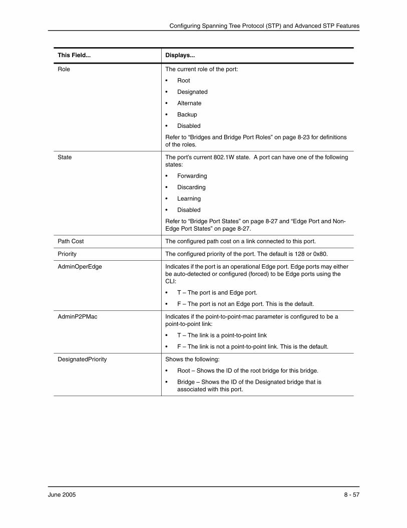
Configuring Spanning Tree Protocol (STP) and Advanced STP Features
Role The current role of the port:
• Root
• Designated
• Alternate
• Backup
• Disabled
Refer to “Bridges and Bridge Port Roles” on page 8-23 for definitions of the roles.
State The port’s current 802.1W state. A port can have one of the following states:
• Forwarding
• Discarding
• Learning
• Disabled
Refer to “Bridge Port States” on page 8-27 and “Edge Port and Non-Edge Port States” on page 8-27.
Path Cost The configured path cost on a link connected to this port.
Priority The configured priority of the port. The default is 128 or 0x80.
AdminOperEdge Indicates if the port is an operational Edge port. Edge ports may either be auto-detected or configured (forced) to be Edge ports using the CLI:
• T – The port is and Edge port.
• F – The port is not an Edge port. This is the default.
AdminP2PMac Indicates if the point-to-point-mac parameter is configured to be a point-to-point link:
• T – The link is a point-to-point link
• F – The link is not a point-to-point link. This is the default.
DesignatedPriority Shows the following:
• Root – Shows the ID of the root bridge for this bridge.
• Bridge – Shows the ID of the Designated bridge that is associated with this port.
This Field... Displays...
June 2005 8 - 57
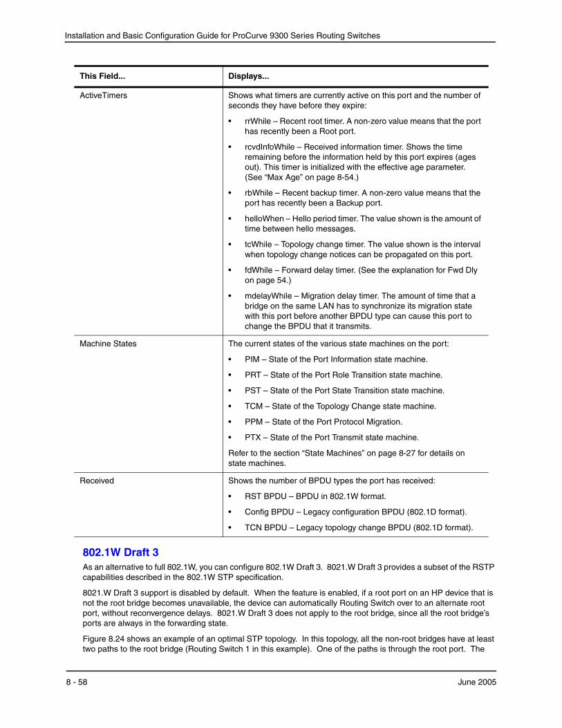
Installation and Basic Configuration Guide for ProCurve 9300 Series Routing Switches
802.1W Draft 3As an alternative to full 802.1W, you can configure 802.1W Draft 3. 8021.W Draft 3 provides a subset of the RSTP capabilities described in the 802.1W STP specification.
8021.W Draft 3 support is disabled by default. When the feature is enabled, if a root port on an HP device that is not the root bridge becomes unavailable, the device can automatically Routing Switch over to an alternate root port, without reconvergence delays. 8021.W Draft 3 does not apply to the root bridge, since all the root bridge’s ports are always in the forwarding state.
Figure 8.24 shows an example of an optimal STP topology. In this topology, all the non-root bridges have at least two paths to the root bridge (Routing Switch 1 in this example). One of the paths is through the root port. The
ActiveTimers Shows what timers are currently active on this port and the number of seconds they have before they expire:
• rrWhile – Recent root timer. A non-zero value means that the port has recently been a Root port.
• rcvdInfoWhile – Received information timer. Shows the time remaining before the information held by this port expires (ages out). This timer is initialized with the effective age parameter. (See “Max Age” on page 8-54.)
• rbWhile – Recent backup timer. A non-zero value means that the port has recently been a Backup port.
• helloWhen – Hello period timer. The value shown is the amount of time between hello messages.
• tcWhile – Topology change timer. The value shown is the interval when topology change notices can be propagated on this port.
• fdWhile – Forward delay timer. (See the explanation for Fwd Dly on page 54.)
• mdelayWhile – Migration delay timer. The amount of time that a bridge on the same LAN has to synchronize its migration state with this port before another BPDU type can cause this port to change the BPDU that it transmits.
Machine States The current states of the various state machines on the port:
• PIM – State of the Port Information state machine.
• PRT – State of the Port Role Transition state machine.
• PST – State of the Port State Transition state machine.
• TCM – State of the Topology Change state machine.
• PPM – State of the Port Protocol Migration.
• PTX – State of the Port Transmit state machine.
Refer to the section “State Machines” on page 8-27 for details on state machines.
Received Shows the number of BPDU types the port has received:
• RST BPDU – BPDU in 802.1W format.
• Config BPDU – Legacy configuration BPDU (802.1D format).
• TCN BPDU – Legacy topology change BPDU (802.1D format).
This Field... Displays...
8 - 58 June 2005
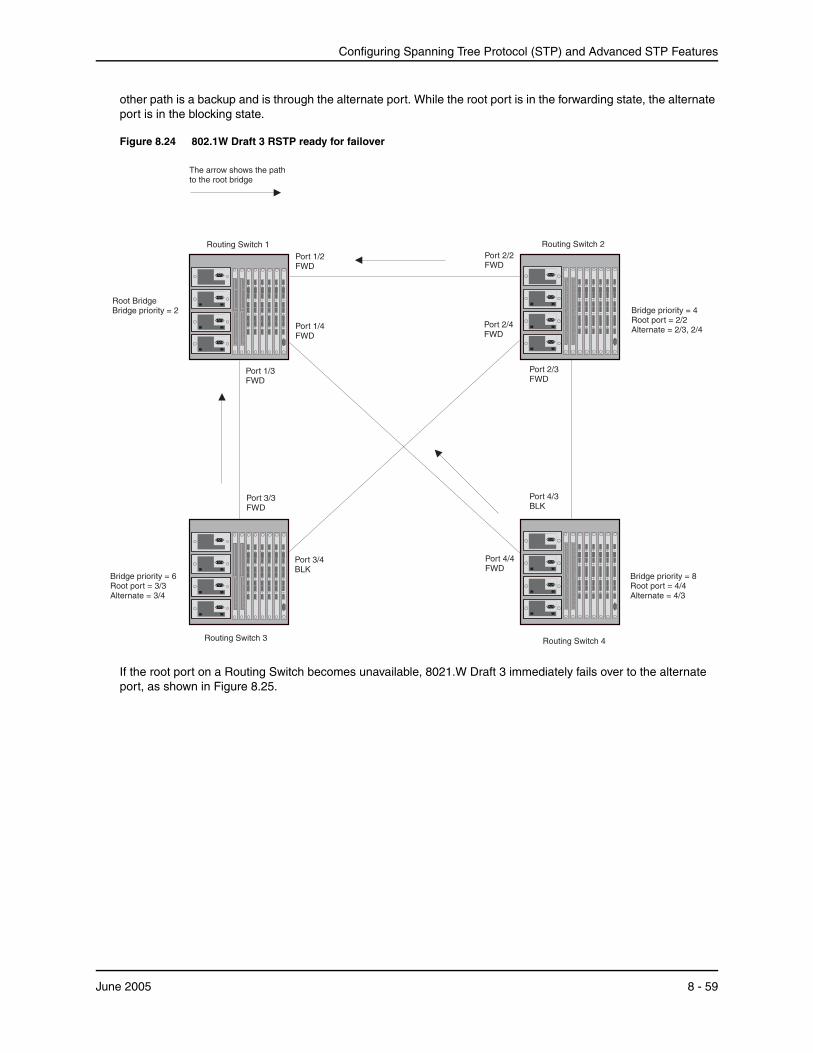
Configuring Spanning Tree Protocol (STP) and Advanced STP Features
other path is a backup and is through the alternate port. While the root port is in the forwarding state, the alternate port is in the blocking state.
Figure 8.24 802.1W Draft 3 RSTP ready for failover
Routing Switch 4Routing Switch 3
Routing Switch 2
Port 2/4FWD
Bridge priority = 6Root port = 3/3Alternate = 3/4
Port 2/2FWD
Port 2/3FWD
Port 1/2FWD
Port 3/4BLK
Port 1/4FWD
Port 1/3FWD
Port 4/4FWD
Port 3/3FWD
Port 4/3BLK
Routing Switch 1
The arrow shows the pathto the root bridge
Bridge priority = 8Root port = 4/4Alternate = 4/3
Bridge priority = 4Root port = 2/2Alternate = 2/3, 2/4
Root BridgeBridge priority = 2
If the root port on a Routing Switch becomes unavailable, 8021.W Draft 3 immediately fails over to the alternate port, as shown in Figure 8.25.
June 2005 8 - 59
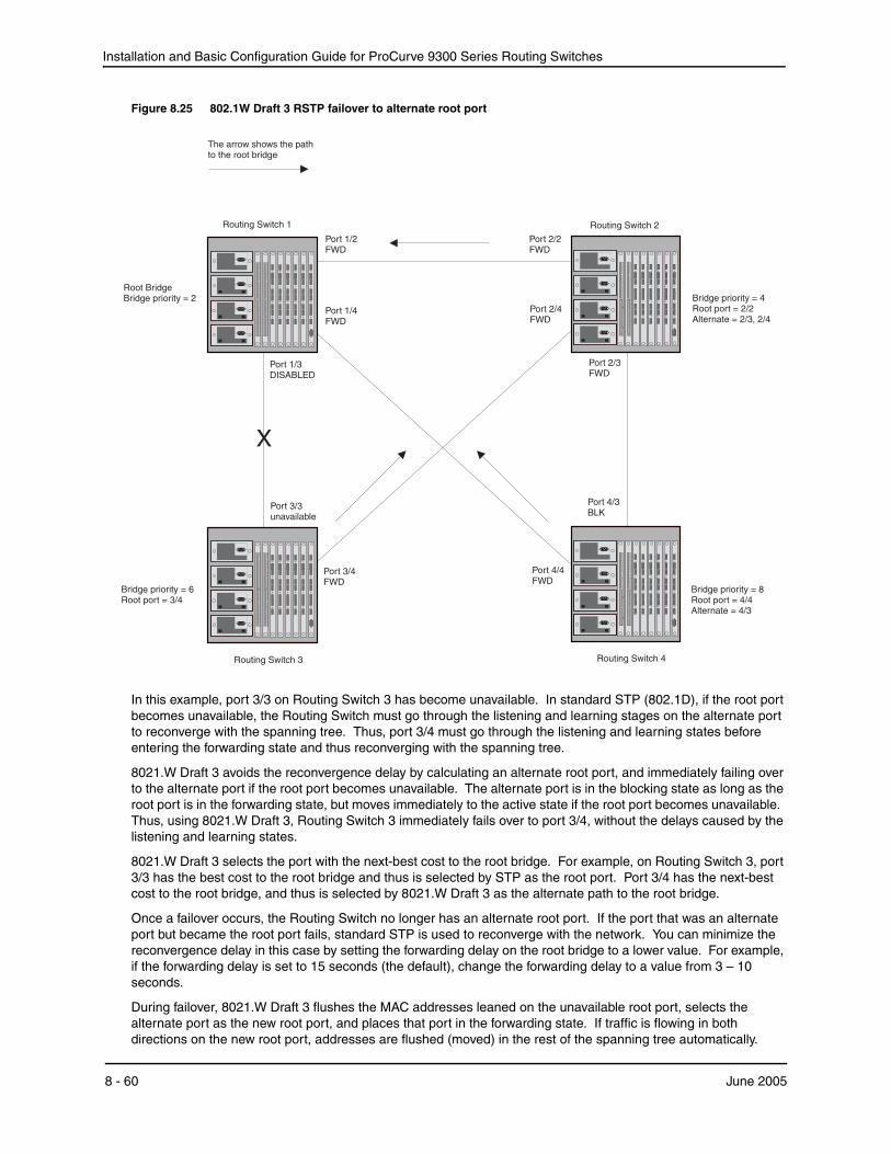
Installation and Basic Configuration Guide for ProCurve 9300 Series Routing Switches
Figure 8.25 802.1W Draft 3 RSTP failover to alternate root port
Routing Switch 4Routing Switch 3
Routing Switch 2
Port 2/4FWD
Bridge priority = 6Root port = 3/4
Port 2/2FWD
Port 2/3FWD
Port 1/2FWD
Port 3/4FWD
Port 1/4FWD
Port 1/3DISABLED
Port 4/4FWD
Port 3/3unavailable
Port 4/3BLK
Routing Switch 1
The arrow shows the pathto the root bridge
Bridge priority = 8Root port = 4/4Alternate = 4/3
Bridge priority = 4Root port = 2/2Alternate = 2/3, 2/4
Root BridgeBridge priority = 2
X
In this example, port 3/3 on Routing Switch 3 has become unavailable. In standard STP (802.1D), if the root port becomes unavailable, the Routing Switch must go through the listening and learning stages on the alternate port to reconverge with the spanning tree. Thus, port 3/4 must go through the listening and learning states before entering the forwarding state and thus reconverging with the spanning tree.
8021.W Draft 3 avoids the reconvergence delay by calculating an alternate root port, and immediately failing over to the alternate port if the root port becomes unavailable. The alternate port is in the blocking state as long as the root port is in the forwarding state, but moves immediately to the active state if the root port becomes unavailable. Thus, using 8021.W Draft 3, Routing Switch 3 immediately fails over to port 3/4, without the delays caused by the listening and learning states.
8021.W Draft 3 selects the port with the next-best cost to the root bridge. For example, on Routing Switch 3, port 3/3 has the best cost to the root bridge and thus is selected by STP as the root port. Port 3/4 has the next-best cost to the root bridge, and thus is selected by 8021.W Draft 3 as the alternate path to the root bridge.
Once a failover occurs, the Routing Switch no longer has an alternate root port. If the port that was an alternate port but became the root port fails, standard STP is used to reconverge with the network. You can minimize the reconvergence delay in this case by setting the forwarding delay on the root bridge to a lower value. For example, if the forwarding delay is set to 15 seconds (the default), change the forwarding delay to a value from 3 – 10 seconds.
During failover, 8021.W Draft 3 flushes the MAC addresses leaned on the unavailable root port, selects the alternate port as the new root port, and places that port in the forwarding state. If traffic is flowing in both directions on the new root port, addresses are flushed (moved) in the rest of the spanning tree automatically.
8 - 60 June 2005
Configuring Spanning Tree Protocol (STP) and Advanced STP Features
Reconvergence Time
Spanning tree reconvergence using 8021.W Draft 3 can occur within one second.
After the spanning tree reconverges following the topology change, traffic also must reconverge on all the bridges attached to the spanning tree. This is true regardless of whether 8021.W Draft 3 or standard STP is used to reconverge the spanning tree.
Traffic reconvergence happens after the spanning tree reconvergence, and is achieved by flushing the Layer 2 information on the bridges.
• Following 8021.W Draft 3 reconvergence of the spanning tree, traffic reconvergence occurs in the time it takes for the bridge to detect the link changes plus the STP maximum age set on the bridge.
• If standard STP reconvergence occurs instead, traffic reconvergence takes two times the forward delay plus the maximum age.
NOTE: 8021.W Draft 3 does not apply when a failed root port comes back up. In this case, standard STP is used.
Configuration Considerations
8021.W Draft 3 is disabled by default. To ensure optimal performance of the feature before you enable it:
• Configure the bridge priorities so that the root bridge is one that supports 8021.W Draft 3. (Use an HP device or third-party device that supports 8021.W Draft 3.)
• Change the forwarding delay on the root bridge to a value lower than the default 15 seconds. HP recommends a value from 3 – 10 seconds. The lower forwarding delay helps reduce reconvergence delays in cases where 8021.W Draft 3 is not applicable, such as when a failed root port comes back up.
• Configure the bridge priorities and root port costs so that each device has an active path to the root bridge if its root port becomes unavailable. For example, port 3/4 is connected to port 2/4 on Routing Switch 2, which has the second most favorable bridge priority in the spanning tree.
NOTE: If reconvergence involves changing the state of a root port on a bridge that supports 802.1D STP but not 8021.W Draft 3, then reconvergence still requires the amount of time it takes for the ports on the 802.1D bridge to change state to forwarding (as needed), and receive BPDUs from the root bridge for the new topology.
Enabling 8021.W Draft 3
8021.W Draft 3 is disabled by default. The procedure for enabling the feature differs depending on whether single STP is enabled on the device.
NOTE: STP must be enabled before you can enable 8021.W Draft 3.
Enabling 8021.W Draft 3 When Single STP Is Not EnabledTo enable 8021.W Draft 3 on a device that is not running single STP, use the following CLI method.
USING THE CLI
By default, each port-based VLAN on the device has its own spanning tree. To enable 8021.W Draft 3 in a port-based VLAN, enter commands such as the following:
ProCurveRS(config)# vlan 10 ProCurveRS(config-vlan-10)# spanning-tree rstp
Syntax: [no] spanning-tree rstp
This command enables 8021.W Draft 3. You must enter the command separately in each port-based VLAN in which you want to run 8021.W Draft 3.
June 2005 8 - 61
Installation and Basic Configuration Guide for ProCurve 9300 Series Routing Switches
NOTE: This command does not also enable STP. To enable STP, first enter the spanning-tree command without the rstp parameter. After you enable STP, enter the spanning-tree rstp command to enable 8021.W Draft 3.
To disable 8021.W Draft 3, enter the following command:
ProCurveRS(config-vlan-10)# no spanning-tree rstp
Enabling 8021.W Draft 3 When Single STP Is EnabledTo enable 8021.W Draft 3 on a device that is running single STP, enter the following command at the global CONFIG level of the CLI:
ProCurveRS(config)# spanning-tree single rstp
Syntax: [no] spanning-tree single rstp
This command enables 8021.W Draft 3 on the whole device.
NOTE: This command does not also enable single STP. To enable single STP, first enter the spanning-tree single command without the rstp parameter. After you enable single STP, enter the spanning-tree single rstp command to enable 8021.W Draft 3.
To disable 8021.W Draft 3 on a device that is running single STP, enter the following command:
ProCurveRS(config)# no spanning-tree single rstp
Single Spanning Tree (SSTP)By default, each port-based VLAN on an HP device runs a separate spanning tree, which you can enable or disable on an individual VLAN basis.
Alternatively, you can configure an HP device to run a single spanning tree across all ports and VLANs on the device. The Single STP feature (SSTP) is especially useful for connecting an HP device to third-party devices that run a single spanning tree in accordance with the 802.1q specification.
SSTP uses the same parameters, with the same value ranges and defaults, as the default STP support on HP devices. See “STP Parameters and Defaults” on page 8-2.
SSTP Defaults
SSTP is disabled by default. When you enable the feature, all VLANs on which STP is enabled become members of a single spanning tree. All VLANs on which STP is disabled are excluded from the single spanning tree.
• To add a VLAN to the single spanning tree, enable STP on that VLAN.
• To remove a VLAN from the single spanning tree, disable STP on that VLAN.
When you enable SSTP, all the ports that are in port-based VLANs with STP enabled become members of a single spanning tree domain. Thus, the ports share a single BPDU broadcast domain. The HP device places all the ports in a non-configurable VLAN, 4094, to implement the SSTP domain. However, this VLAN does not affect port membership in the port-based VLANs you have configured. Other broadcast traffic is still contained within the individual port-based VLANs. Therefore, you can use SSTP while still using your existing VLAN configurations without changing your network. In addition, SSTP does not affect 802.1q tagging. Tagged and untagged ports alike can be members of the single spanning tree domain.
NOTE: When SSTP is enabled, the BPDUs on tagged ports go out untagged.
If you disable SSTP, all VLANs that were members of the single spanning tree run MSTP instead. In MSTP, each VLAN has its own spanning tree. VLANs that were not members of the single spanning tree were not enabled for STP. Therefore, STP remains disabled on those VLANs.
Enabling SSTP
To enable SSTP, use one of the following methods.
8 - 62 June 2005

Configuring Spanning Tree Protocol (STP) and Advanced STP Features
NOTE: If the device has only one port-based VLAN (the default VLAN), then the device is already running a single instance of STP. In this case, you do not need to enable SSTP. You need to enable SSTP only if the device contains more than one port-based VLAN and you want all the ports to be in the same STP broadcast domain.
USING THE CLI
To configure the HP device to run a single spanning tree, enter the following command at the global CONFIG level.
ProCurveRS(config)# spanning-tree single
NOTE: If the device has only one port-based VLAN, the CLI command for enabling SSTP is not listed in the CLI. The command is listed only if you have configured a port-based VLAN.
To change a global STP parameter, enter a command such as the following at the global CONFIG level:
ProCurveRS(config) spanning-tree single priority 2
This command changes the STP priority for all ports to 2.
To change an STP parameter for a specific port, enter commands such as the following:
ProCurveRS(config) spanning-tree single ethernet 1/1 priority 10
The commands shown above override the global setting for STP priority and set the priority to 10 for port 1/1.
Here is the syntax for the global STP parameters.
Syntax: [no] spanning-tree single [forward-delay <value>] [hello-time <value>] | [maximum-age <time>] | [priority <value>]
Here is the syntax for the STP port parameters.
Syntax: [no] spanning-tree single [ethernet <portnum> path-cost <value> | priority <value>]
NOTE: Both commands listed above are entered at the global CONFIG level.
USING THE WEB MANAGEMENT INTERFACE
1. Log on to the device using a valid user name and password for read-write access.
2. Click the Single checkbox next to Spanning Tree to place a checkmark in the box.
3. Make sure Enable, not Disable, is selected next to Spanning Tree.
4. Click Apply to apply the change to the device’s running-config.
5. Select the Save link at the bottom of the panel. Select Yes when prompted to save the configuration change to the startup-config file on the device’s flash memory.
Displaying SSTP information
To verify that SSTP is in effect, enter the following commands at any level of the CLI:
ProCurveRS(config)# show span
Syntax: show span [vlan <vlan-id>] | [pvst-mode] | [<num>] | [detail [vlan <vlan-id> [ ethernet <portnum> ] | <num>]]
The vlan <vlan-id> parameter displays STP information for the specified port-based VLAN.
The pvst-mode parameter displays STP information for the device’s Per VLAN Spanning Tree (PVST+) compatibility configuration. See “PVST/PVST+ Compatibility” on page 8-75.
The <num> parameter displays only the entries after the number you specify. For example, on a device with three port-based VLANs, if you enter 1, then information for the second and third VLANs is displayed, but information for the first VLAN is not displayed. Information is displayed according to VLAN number, in ascending order. The entry number is not the same as the VLAN number. For example, if you have port-based VLANs 1, 10, and 2024,
June 2005 8 - 63
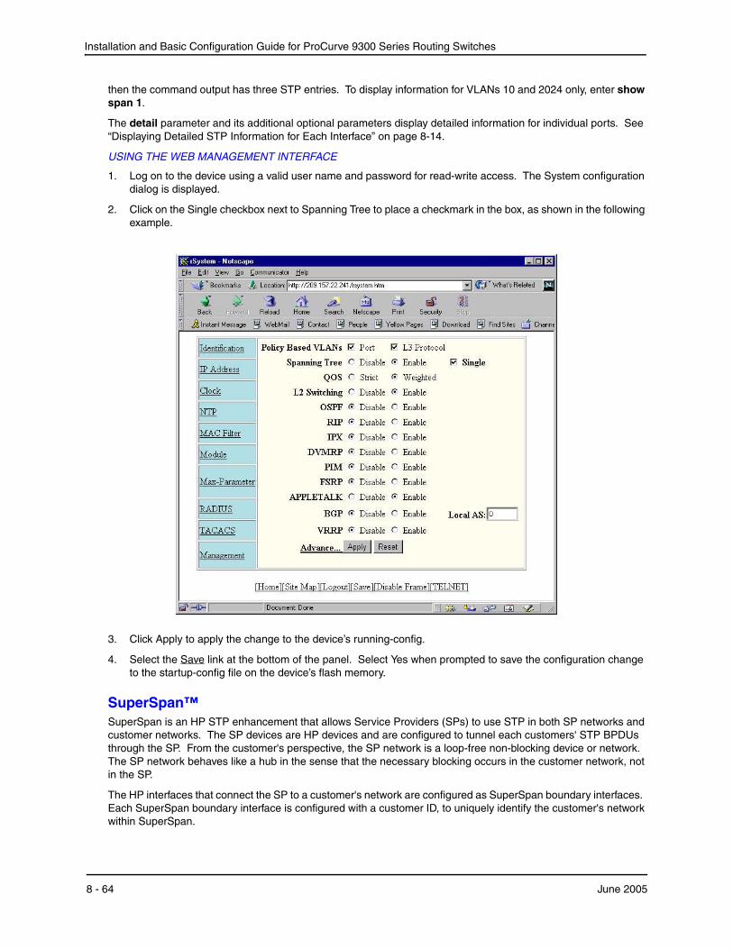
Installation and Basic Configuration Guide for ProCurve 9300 Series Routing Switches
then the command output has three STP entries. To display information for VLANs 10 and 2024 only, enter show span 1.
The detail parameter and its additional optional parameters display detailed information for individual ports. See “Displaying Detailed STP Information for Each Interface” on page 8-14.
USING THE WEB MANAGEMENT INTERFACE
1. Log on to the device using a valid user name and password for read-write access. The System configuration dialog is displayed.
2. Click on the Single checkbox next to Spanning Tree to place a checkmark in the box, as shown in the following example.
3. Click Apply to apply the change to the device’s running-config.
4. Select the Save link at the bottom of the panel. Select Yes when prompted to save the configuration change to the startup-config file on the device’s flash memory.
SuperSpan™SuperSpan is an HP STP enhancement that allows Service Providers (SPs) to use STP in both SP networks and customer networks. The SP devices are HP devices and are configured to tunnel each customers' STP BPDUs through the SP. From the customer's perspective, the SP network is a loop-free non-blocking device or network. The SP network behaves like a hub in the sense that the necessary blocking occurs in the customer network, not in the SP.
The HP interfaces that connect the SP to a customer's network are configured as SuperSpan boundary interfaces. Each SuperSpan boundary interface is configured with a customer ID, to uniquely identify the customer's network within SuperSpan.
8 - 64 June 2005
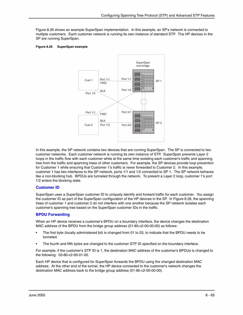
Configuring Spanning Tree Protocol (STP) and Advanced STP Features
Figure 8.26 shows an example SuperSpan implementation. In this example, an SP's network is connected to multiple customers. Each customer network is running its own instance of standard STP. The HP devices in the SP are running SuperSpan.
Figure 8.26 SuperSpan example
Port 2/1
SuperSpanroot bridge
Port 1/2
FWD
Cust 2
BLK
BLK
SP 2
Cust 1 Port 1/1
Port 1/2
FWDSP 1
Port 1/1
Port 1/2 Port 2/2
Port 1/1
In this example, the SP network contains two devices that are running SuperSpan. The SP is connected to two customer networks. Each customer network is running its own instance of STP. SuperSpan prevents Layer 2 loops in the traffic flow with each customer while at the same time isolating each customer’s traffic and spanning tree from the traffic and spanning trees of other customers. For example, the SP devices provide loop prevention for Customer 1 while ensuring that Customer 1’s traffic is never forwarded to Customer 2. In this example, customer 1 has two interfaces to the SP network, ports 1/1 and 1/2 connected to SP 1. The SP network behaves like a non-blocking hub. BPDUs are tunneled through the network. To prevent a Layer 2 loop, customer 1’s port 1/2 enters the blocking state.
Customer ID
SuperSpan uses a SuperSpan customer ID to uniquely identify and forward traffic for each customer. You assign the customer ID as part of the SuperSpan configuration of the HP devices in the SP. In Figure 8.26, the spanning trees of customer 1 and customer 2 do not interfere with one another because the SP network isolates each customer’s spanning tree based on the SuperSpan customer IDs in the traffic.
BPDU Forwarding
When an HP device receives a customer's BPDU on a boundary interface, the device changes the destination MAC address of the BPDU from the bridge group address (01-80-c2-00-00-00) as follows:
• The first byte (locally administered bit) is changed from 01 to 03, to indicate that the BPDU needs to be tunneled.
• The fourth and fifth bytes are changed to the customer STP ID specified on the boundary interface.
For example, if the customer's STP ID is 1, the destination MAC address of the customer's BPDUs is changed to the following: 03-80-c2-00-01-00.
Each HP device that is configured for SuperSpan forwards the BPDU using the changed destination MAC address. At the other end of the tunnel, the HP device connected to the customer's network changes the destination MAC address back to the bridge group address (01-80-c2-00-00-00).
June 2005 8 - 65
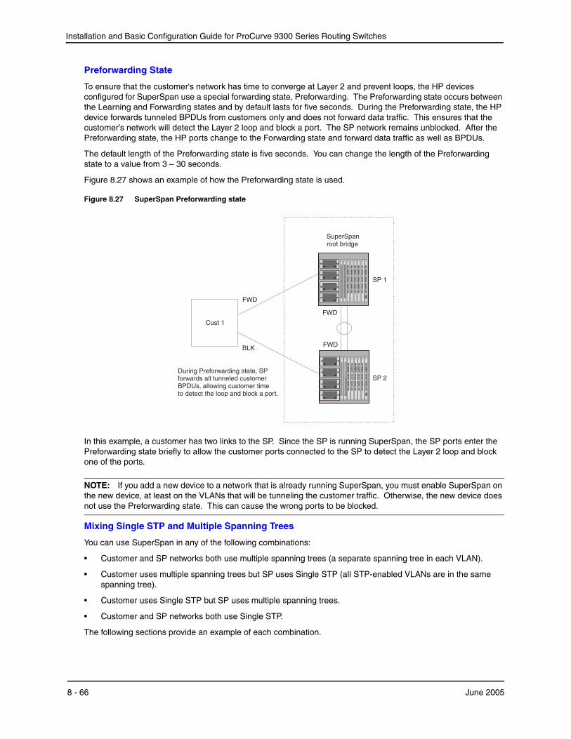
Installation and Basic Configuration Guide for ProCurve 9300 Series Routing Switches
Preforwarding State
To ensure that the customer's network has time to converge at Layer 2 and prevent loops, the HP devices configured for SuperSpan use a special forwarding state, Preforwarding. The Preforwarding state occurs between the Learning and Forwarding states and by default lasts for five seconds. During the Preforwarding state, the HP device forwards tunneled BPDUs from customers only and does not forward data traffic. This ensures that the customer’s network will detect the Layer 2 loop and block a port. The SP network remains unblocked. After the Preforwarding state, the HP ports change to the Forwarding state and forward data traffic as well as BPDUs.
The default length of the Preforwarding state is five seconds. You can change the length of the Preforwarding state to a value from 3 – 30 seconds.
Figure 8.27 shows an example of how the Preforwarding state is used.
Figure 8.27 SuperSpan Preforwarding state
During Preforwarding state, SPforwards all tunneled customerBPDUs, allowing customer timeto detect the loop and block a port.
BLK
SP 2
Cust 1
FWD
SP 1
FWD
FWD
SuperSpanroot bridge
In this example, a customer has two links to the SP. Since the SP is running SuperSpan, the SP ports enter the Preforwarding state briefly to allow the customer ports connected to the SP to detect the Layer 2 loop and block one of the ports.
NOTE: If you add a new device to a network that is already running SuperSpan, you must enable SuperSpan on the new device, at least on the VLANs that will be tunneling the customer traffic. Otherwise, the new device does not use the Preforwarding state. This can cause the wrong ports to be blocked.
Mixing Single STP and Multiple Spanning Trees
You can use SuperSpan in any of the following combinations:
• Customer and SP networks both use multiple spanning trees (a separate spanning tree in each VLAN).
• Customer uses multiple spanning trees but SP uses Single STP (all STP-enabled VLANs are in the same spanning tree).
• Customer uses Single STP but SP uses multiple spanning trees.
• Customer and SP networks both use Single STP.
The following sections provide an example of each combination.
8 - 66 June 2005

Configuring Spanning Tree Protocol (STP) and Advanced STP Features
NOTE: All the combinations listed above are supported when the boundary ports joining the SP SuperSpan domain to the client spanning trees are untagged. For example, all these combinations are valid in super aggregated VLAN configurations. If the boundary ports are tagged, you cannot use Single STP in the client network in combination with multiple spanning trees in the SP SuperSpan domain.
Customer and SP Use Multiple Spanning TreesFigure 8.28 shows an example of SuperSpan where both the customer network and the SP network use multiple spanning trees (a separate spanning tree in each port-based VLAN).
Figure 8.28 Customer and SP using multiple spanning trees
Customer
Region
Provider
Region
R 10
R 20
R100
R200
tagged to multiple vlan R xx
Root bridge for VLAN xx
2/1
2/1
1/1
3/1
2/2
2/2
stp-boundary
untagged to vlan 100
Both the customer and SP regions are running multiple spanning trees (one per port-based VLAN) in the Layer 2 switched network. The customer network contains VLANs 10 and 20 while the SP network contains VLANs 100 and 200. Customer traffic from VLAN 10 and VLAN 20 is aggregated by VLAN 100 in the SP since the boundary ports, 2/1 on R100 and R200, are untagged members of VLAN 100. By adjusting the bridge priority on VLANs 10 and 20, the customer can select a different root bridge for each spanning tree running in the customer network.
In the above example, STP in VLAN 10 will select R10 as the root bridge and make 1/1 on R10 forwarding while blocking port 3/1 on R20. The opposite occurs for STP in VLAN 20. As a result, both links connecting the customer and SP regions are fully utilized and serve as backup links at the same time, providing loop-free, non-blocking connectivity. In the SP network, multiple STP instances are running (one for VLAN 100 and one for VLAN 200) to ensure loop-free, non-blocking connectivity in each VLAN.
SuperSPAN boundaries are configured at port 2/1 of R100 and R200. Since the customer’s traffic will be aggregated into VLAN 100 at the SP, the SP network appears to the customer to be a loop-free non-blocking hub to the customer network when port 2/2 on R200 is blocked by STP in VLAN 100.
Customer Uses Multiple Spanning Trees But SP Uses Single STPFigure 8.29 shows an example of SuperSpan where the customer network uses multiple spanning trees while the SP network uses Single STP.
June 2005 8 - 67
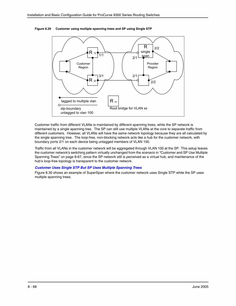
Installation and Basic Configuration Guide for ProCurve 9300 Series Routing Switches
Figure 8.29 Customer using multiple spanning trees and SP using Single STP
Customer
Region
Provider
Region
R 10
R 20
Rsingle
span
tagged to multiple vlan R xx
Root bridge for VLAN xx
2/1
2/1
1/1
3/1
2/2
2/2
stp-boundary
untagged to vlan 100
Customer traffic from different VLANs is maintained by different spanning trees, while the SP network is maintained by a single spanning tree. The SP can still use multiple VLANs at the core to separate traffic from different customers. However, all VLANs will have the same network topology because they are all calculated by the single spanning tree. The loop-free, non-blocking network acts like a hub for the customer network, with boundary ports 2/1 on each device being untagged members of VLAN 100.
Traffic from all VLANs in the customer network will be aggregated through VLAN 100 at the SP. This setup leaves the customer network’s switching pattern virtually unchanged from the scenario in “Customer and SP Use Multiple Spanning Trees” on page 8-67, since the SP network still is perceived as a virtual hub, and maintenance of the hub's loop-free topology is transparent to the customer network.
Customer Uses Single STP But SP Uses Multiple Spanning TreesFigure 8.30 shows an example of SuperSpan where the customer network uses Single STP while the SP uses multiple spanning trees.
8 - 68 June 2005
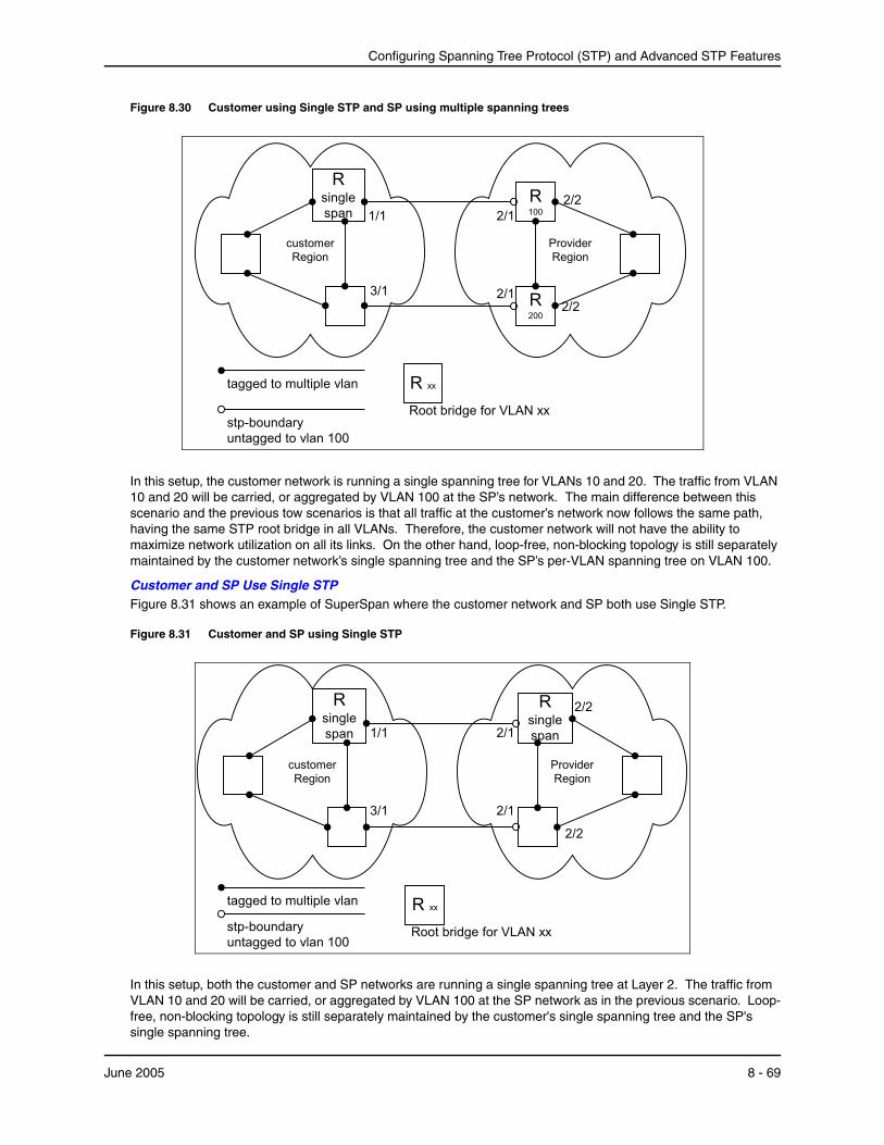
Configuring Spanning Tree Protocol (STP) and Advanced STP Features
Figure 8.30 Customer using Single STP and SP using multiple spanning trees
customer
Region
Provider
Region
Rsingle
span
R100
R200
tagged to multiple vlan R xx
Root bridge for VLAN xx
2/1
2/1
1/1
3/1
2/2
2/2
stp-boundary
untagged to vlan 100
In this setup, the customer network is running a single spanning tree for VLANs 10 and 20. The traffic from VLAN 10 and 20 will be carried, or aggregated by VLAN 100 at the SP’s network. The main difference between this scenario and the previous tow scenarios is that all traffic at the customer’s network now follows the same path, having the same STP root bridge in all VLANs. Therefore, the customer network will not have the ability to maximize network utilization on all its links. On the other hand, loop-free, non-blocking topology is still separately maintained by the customer network’s single spanning tree and the SP’s per-VLAN spanning tree on VLAN 100.
Customer and SP Use Single STPFigure 8.31 shows an example of SuperSpan where the customer network and SP both use Single STP.
Figure 8.31 Customer and SP using Single STP
customer
Region
Provider
Region
Rsingle
span
Rsingle
span
tagged to multiple vlan
stp-boundary
untagged to vlan 100
R xx
Root bridge for VLAN xx
1/1
3/1
2/1
2/1
2/2
2/2
In this setup, both the customer and SP networks are running a single spanning tree at Layer 2. The traffic from VLAN 10 and 20 will be carried, or aggregated by VLAN 100 at the SP network as in the previous scenario. Loop-free, non-blocking topology is still separately maintained by the customer's single spanning tree and the SP's single spanning tree.
June 2005 8 - 69
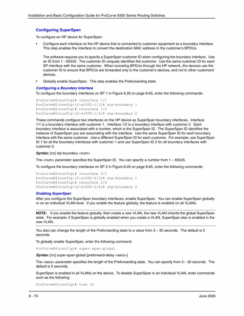
Installation and Basic Configuration Guide for ProCurve 9300 Series Routing Switches
Configuring SuperSpan
To configure an HP device for SuperSpan:
• Configure each interface on the HP device that is connected to customer equipment as a boundary interface. This step enables the interface to convert the destination MAC address in the customer's BPDUs. The software requires you to specify a SuperSpan customer ID when configuring the boundary interface. Use an ID from 1 – 65535. The customer ID uniquely identifies the customer. Use the same customer ID for each SP interface with the same customer. When tunneling BPDUs through the HP network, the devices use the customer ID to ensure that BPDUs are forwarded only to the customer's devices, and not to other customers' devices.
• Globally enable SuperSpan. This step enables the Preforwarding state.
Configuring a Boundary InterfaceTo configure the boundary interfaces on SP 1 in Figure 8.26 on page 8-65, enter the following commands:
ProCurveRS(config)# interface 1/1 ProCurveRS(config-if-e1000-1/1)# stp-boundary 1 ProCurveRS(config)# interface 1/2 ProCurveRS(config-if-e1000-1/2)# stp-boundary 2
These commands configure two interfaces on the HP device as SuperSpan boundary interfaces. Interface 1/1 is a boundary interface with customer 1. Interface 1/2 is a boundary interface with customer 2. Each boundary interface is associated with a number, which is the SuperSpan ID. The SuperSpan ID identifies the instance of SuperSpan you are associating with the interface. Use the same SuperSpan ID for each boundary interface with the same customer. Use a different SuperSpan ID for each customer. For example, use SuperSpan ID 1 for all the boundary interfaces with customer 1 and use SuperSpan ID 2 for all boundary interfaces with customer 2.
Syntax: [no] stp-boundary <num>
The <num> parameter specifies the SuperSpan ID. You can specify a number from 1 – 65535.
To configure the boundary interfaces on SP 2 in Figure 8.26 on page 8-65, enter the following commands:
ProCurveRS(config)# interface 2/1 ProCurveRS(config-if-e1000-2/1)# stp-boundary 1 ProCurveRS(config)# interface 2/2 ProCurveRS(config-if-e1000-2/2)# stp-boundary 2
Enabling SuperSpanAfter you configure the SuperSpan boundary interfaces, enable SuperSpan. You can enable SuperSpan globally or on an individual VLAN level. If you enable the feature globally, the feature is enabled on all VLANs.
NOTE: If you enable the feature globally, then create a new VLAN, the new VLAN inherits the global SuperSpan state. For example, if SuperSpan is globally enabled when you create a VLAN, SuperSpan also is enabled in the new VLAN.
You also can change the length of the Preforwarding state to a value from 3 – 30 seconds. The default is 5 seconds.
To globally enable SuperSpan, enter the following command:
ProCurveRS(config)# super-span-global
Syntax: [no] super-span-global [preforward-delay <secs>]
The <secs> parameter specifies the length of the Preforwarding state. You can specify from 3 – 30 seconds. The default is 5 seconds.
SuperSpan is enabled in all VLANs on the device. To disable SuperSpan in an individual VLAN, enter commands such as the following:
ProCurveRS(config)# vlan 10
8 - 70 June 2005
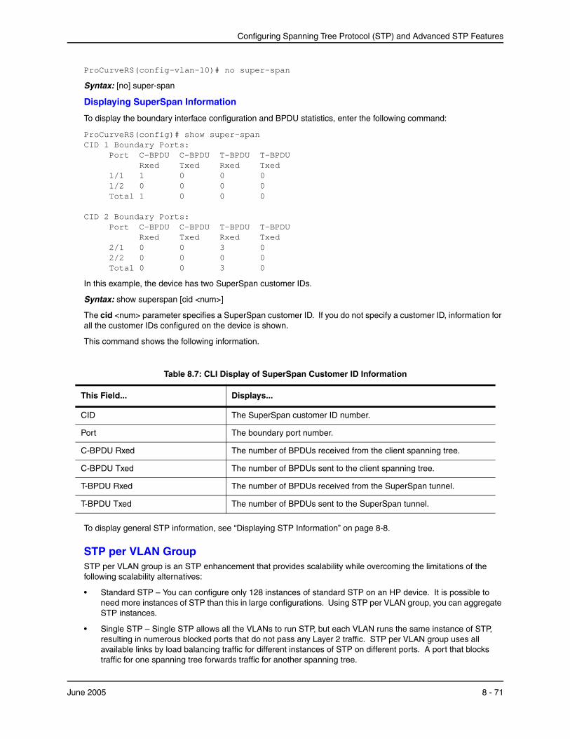
Configuring Spanning Tree Protocol (STP) and Advanced STP Features
ProCurveRS(config-vlan-10)# no super-span
Syntax: [no] super-span
Displaying SuperSpan Information
To display the boundary interface configuration and BPDU statistics, enter the following command:
ProCurveRS(config)# show super-span CID 1 Boundary Ports: Port C-BPDU C-BPDU T-BPDU T-BPDU Rxed Txed Rxed Txed 1/1 1 0 0 0 1/2 0 0 0 0 Total 1 0 0 0 CID 2 Boundary Ports: Port C-BPDU C-BPDU T-BPDU T-BPDU Rxed Txed Rxed Txed 2/1 0 0 3 0 2/2 0 0 0 0 Total 0 0 3 0
In this example, the device has two SuperSpan customer IDs.
Syntax: show superspan [cid <num>]
The cid <num> parameter specifies a SuperSpan customer ID. If you do not specify a customer ID, information for all the customer IDs configured on the device is shown.
This command shows the following information.
Table 8.7: CLI Display of SuperSpan Customer ID Information
This Field... Displays...
CID The SuperSpan customer ID number.
Port The boundary port number.
C-BPDU Rxed The number of BPDUs received from the client spanning tree.
C-BPDU Txed The number of BPDUs sent to the client spanning tree.
T-BPDU Rxed The number of BPDUs received from the SuperSpan tunnel.
T-BPDU Txed The number of BPDUs sent to the SuperSpan tunnel.
To display general STP information, see “Displaying STP Information” on page 8-8.
STP per VLAN GroupSTP per VLAN group is an STP enhancement that provides scalability while overcoming the limitations of the following scalability alternatives:
• Standard STP – You can configure only 128 instances of standard STP on an HP device. It is possible to need more instances of STP than this in large configurations. Using STP per VLAN group, you can aggregate STP instances.
• Single STP – Single STP allows all the VLANs to run STP, but each VLAN runs the same instance of STP, resulting in numerous blocked ports that do not pass any Layer 2 traffic. STP per VLAN group uses all available links by load balancing traffic for different instances of STP on different ports. A port that blocks traffic for one spanning tree forwards traffic for another spanning tree.
June 2005 8 - 71
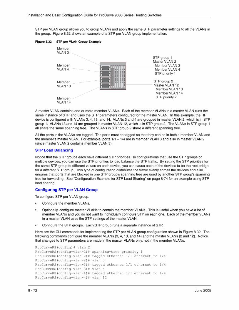
Installation and Basic Configuration Guide for ProCurve 9300 Series Routing Switches
STP per VLAN group allows you to group VLANs and apply the same STP parameter settings to all the VLANs in the group. Figure 8.32 shows an example of a STP per VLAN group implementation.
Figure 8.32 STP per VLAN Group Example
MemberVLAN 14
STP group 2
Member VLAN 14STP priority 2
Master VLAN 12Member VLAN 13
MemberVLAN 4
MemberVLAN 13
MemberVLAN 3
STP group 1Master VLAN 2Member VLAN 3Member VLAN 4STP priority 1
A master VLAN contains one or more member VLANs. Each of the member VLANs in a master VLAN runs the same instance of STP and uses the STP parameters configured for the master VLAN. In this example, the HP device is configured with VLANs 3, 4, 13, and 14. VLANs 3 and 4 are grouped in master VLAN 2, which is in STP group 1. VLANs 13 and 14 are grouped in master VLAN 12, which is in STP group 2. The VLANs in STP group 1 all share the same spanning tree. The VLANs in STP group 2 share a different spanning tree.
All the ports in the VLANs are tagged. The ports must be tagged so that they can be in both a member VLAN and the member's master VLAN. For example, ports 1/1 – 1/4 are in member VLAN 3 and also in master VLAN 2 (since master VLAN 2 contains member VLAN 3).
STP Load Balancing
Notice that the STP groups each have different STP priorities. In configurations that use the STP groups on multiple devices, you can use the STP priorities to load balance the STP traffic. By setting the STP priorities for the same STP group to different values on each device, you can cause each of the devices to be the root bridge for a different STP group. This type of configuration distributes the traffic evenly across the devices and also ensures that ports that are blocked in one STP group’s spanning tree are used by another STP group’s spanning tree for forwarding. See “Configuration Example for STP Load Sharing” on page 8-74 for an example using STP load sharing.
Configuring STP per VLAN Group
To configure STP per VLAN group:
• Configure the member VLANs.
• Optionally, configure master VLANs to contain the member VLANs. This is useful when you have a lot of member VLANs and you do not want to individually configure STP on each one. Each of the member VLANs in a master VLAN uses the STP settings of the master VLAN.
• Configure the STP groups. Each STP group runs a separate instance of STP.
Here are the CLI commands for implementing the STP per VLAN group configuration shown in Figure 8.32. The following commands configure the member VLANs (3, 4, 13, and 14) and the master VLANs (2 and 12). Notice that changes to STP parameters are made in the master VLANs only, not in the member VLANs.
ProCurveRS(config)# vlan 2 ProCurveRS(config-vlan-2)# spanning-tree priority 1 ProCurveRS(config-vlan-2)# tagged ethernet 1/1 ethernet to 1/4 ProCurveRS(config-vlan-2)# vlan 3 ProCurveRS(config-vlan-3)# tagged ethernet 1/1 ethernet to 1/4 ProCurveRS(config-vlan-3)# vlan 4 ProCurveRS(config-vlan-4)# tagged ethernet 1/1 ethernet to 1/4 ProCurveRS(config-vlan-4)# vlan 12
8 - 72 June 2005

Configuring Spanning Tree Protocol (STP) and Advanced STP Features
ProCurveRS(config-vlan-12)# spanning-tree priority 2 ProCurveRS(config-vlan-12)# tagged ethernet 1/1 ethernet to 1/4 ProCurveRS(config-vlan-12)# vlan 13 ProCurveRS(config-vlan-13)# tagged ethernet 1/1 ethernet to 1/4 ProCurveRS(config-vlan-13)# vlan 14 ProCurveRS(config-vlan-14)# tagged ethernet 1/1 ethernet to 1/4 ProCurveRS(config-vlan-14)# exit
The following commands configure the STP groups.
ProCurveRS(config)# stp-group 1 ProCurveRS(config-stp-group-1)# master-vlan 2 ProCurveRS(config-stp-group-1)# member-vlan 3 to 4 ProCurveRS(config-stp-group-1)# exit ProCurveRS(config)# stp-group 2 ProCurveRS(config-stp-group-2)# master-vlan 12 ProCurveRS(config-stp-group-2)# member-vlan 13 to 14
Syntax: [no] stp-group <num>
This command changes the CLI to the STP group configuration level. The following commands are valid at this level. The <num> parameter specifies the STP group ID and can be from 1 – 32.
Syntax: [no] master-vlan <num>
This command adds a master VLAN to the STP group. The master VLAN contains the STP settings for all the VLANs in the STP per VLAN group. The <num> parameter specifies the VLAN ID. An STP group can contain one master VLAN.
NOTE: If you delete the master VLAN from an STP group, the software automatically assigns the first member VLAN in the group to be the new master VLAN for the group.
Syntax: [no] member-vlan <num> [to <num>]
This command adds additional VLANs to the STP group. These VLANs also inherit the STP settings of the master VLAN in the group.
Syntax: [no] member-group <num>
This command adds a member group (a VLAN group) to the STP group. All the VLANs in the member group inherit the STP settings of the master VLAN in the group. The <num> parameter specifies the VLAN group ID.
NOTE: This command is optional and is not used in the example above. For an example of this command, see “Configuration Example for STP Load Sharing”.
June 2005 8 - 73
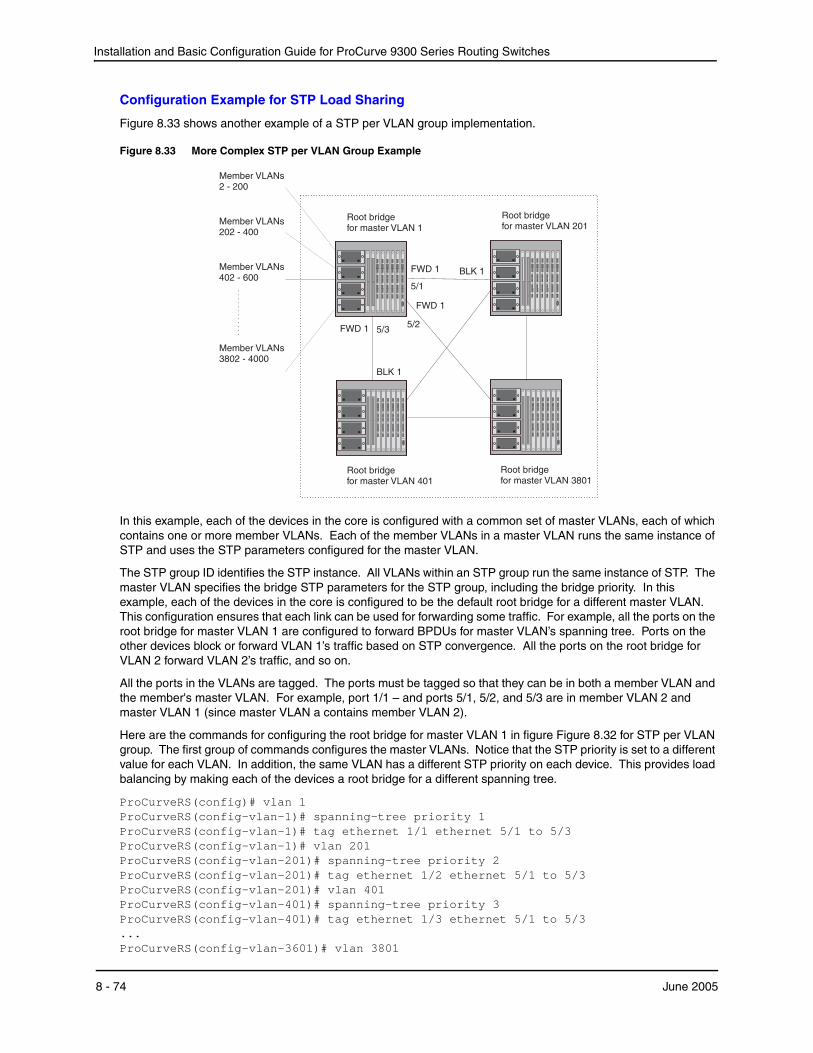
Installation and Basic Configuration Guide for ProCurve 9300 Series Routing Switches
Configuration Example for STP Load Sharing
Figure 8.33 shows another example of a STP per VLAN group implementation.
Figure 8.33 More Complex STP per VLAN Group Example
Root bridgefor master VLAN 401
Root bridgefor master VLAN 3801
Root bridgefor master VLAN 1
Root bridgefor master VLAN 201
FWD 1
5/3FWD 1
BLK 1
FWD 1 BLK 1
Member VLANs3802 - 4000
5/1
5/2
Member VLANs2 - 200
Member VLANs202 - 400
Member VLANs402 - 600
In this example, each of the devices in the core is configured with a common set of master VLANs, each of which contains one or more member VLANs. Each of the member VLANs in a master VLAN runs the same instance of STP and uses the STP parameters configured for the master VLAN.
The STP group ID identifies the STP instance. All VLANs within an STP group run the same instance of STP. The master VLAN specifies the bridge STP parameters for the STP group, including the bridge priority. In this example, each of the devices in the core is configured to be the default root bridge for a different master VLAN. This configuration ensures that each link can be used for forwarding some traffic. For example, all the ports on the root bridge for master VLAN 1 are configured to forward BPDUs for master VLAN’s spanning tree. Ports on the other devices block or forward VLAN 1’s traffic based on STP convergence. All the ports on the root bridge for VLAN 2 forward VLAN 2’s traffic, and so on.
All the ports in the VLANs are tagged. The ports must be tagged so that they can be in both a member VLAN and the member's master VLAN. For example, port 1/1 – and ports 5/1, 5/2, and 5/3 are in member VLAN 2 and master VLAN 1 (since master VLAN a contains member VLAN 2).
Here are the commands for configuring the root bridge for master VLAN 1 in figure Figure 8.32 for STP per VLAN group. The first group of commands configures the master VLANs. Notice that the STP priority is set to a different value for each VLAN. In addition, the same VLAN has a different STP priority on each device. This provides load balancing by making each of the devices a root bridge for a different spanning tree.
ProCurveRS(config)# vlan 1 ProCurveRS(config-vlan-1)# spanning-tree priority 1 ProCurveRS(config-vlan-1)# tag ethernet 1/1 ethernet 5/1 to 5/3 ProCurveRS(config-vlan-1)# vlan 201 ProCurveRS(config-vlan-201)# spanning-tree priority 2 ProCurveRS(config-vlan-201)# tag ethernet 1/2 ethernet 5/1 to 5/3 ProCurveRS(config-vlan-201)# vlan 401 ProCurveRS(config-vlan-401)# spanning-tree priority 3 ProCurveRS(config-vlan-401)# tag ethernet 1/3 ethernet 5/1 to 5/3 ... ProCurveRS(config-vlan-3601)# vlan 3801
8 - 74 June 2005
Configuring Spanning Tree Protocol (STP) and Advanced STP Features
ProCurveRS(config-vlan-3801)# spanning-tree priority 20 ProCurveRS(config-vlan-3801)# tag ethernet 1/20 ethernet 5/1 to 5/3 ProCurveRS(config-vlan-3801)# exit
The next group of commands configures VLAN groups for the member VLANs. Notice that the VLAN groups do not contain the VLAN numbers assigned to the master VLANs. Also notice that no STP parameters are configured for the groups of member VLANs. Each group of member VLANs will inherit its STP settings from its master VLAN.
Set the bridge priority for each master VLAN to the highest priority (1) on one of the devices in the STP per VLAN group configuration. By setting the bridge priority to the highest priority, you make the device the default root bridge for the spanning tree. To ensure STP load balancing, make each of the devices the default root bridge for a different master VLAN.
ProCurveRS(config)# vlan-group 1 vlan 2 to 200 ProCurveRS(config-vlan-group-1)# tag ethernet 1/1 ethernet 5/1 to 5/3 ProCurveRS(config-vlan-group-1)# vlan-group 2 vlan 202 to 400 ProCurveRS(config-vlan-group-2)# tag ethernet 1/2 ethernet 5/1 to 5/3 ProCurveRS(config-vlan-group-2)# vlan-group 3 vlan 402 to 600 ProCurveRS(config-vlan-group-2)# tag ethernet 1/3 ethernet 5/1 to 5/3 ... ProCurveRS(config-vlan-group-19)# vlan-group 20 vlan 3082 to 4000 ProCurveRS(config-vlan-group-20)# tag ethernet 1/20 ethernet 5/1 to 5/3 ProCurveRS(config-vlan-group-20)# exit
The following group of commands configures the STP groups. Each STP group in this configuration contains one master VLAN, which contains a VLAN group. This example shows that an STP group also can contain additional VLANs (VLANs not configured in a VLAN group).
ProCurveRS(config)# stp-group 1 ProCurveRS(config-stp-group-1)# master-vlan 1 ProCurveRS(config-stp-group-1)# member-group 1 ProCurveRS(config-stp-group-1)# member-vlan 4001 4004 to 4010 ProCurveRS(config-stp-group-1)# stp-group 2 ProCurveRS(config-stp-group-2)# master-vlan 201 ProCurveRS(config-stp-group-2)# member-group 2 ProCurveRS(config-stp-group-2)# member-vlan 4002 4003 4011 to 4015 ProCurveRS(config-stp-group-2)# stp-group 3 ProCurveRS(config-stp-group-3)# master-vlan 401 ProCurveRS(config-stp-group-3)# member-group 3 ... ProCurveRS(config-stp-group-19)# stp-group 20 ProCurveRS(config-stp-group-20)# master-vlan 3081 ProCurveRS(config-stp-group-20)# member-group 20
PVST/PVST+ CompatibilityThe following sections describe the Per VLAN Spanning Tree (PVST) and PVST+ compatibility features on HP devices. Use the section that matches the software release you are using:
• For release 07.6.04 and later, see “PVST/PVST+ Compatibility – 07.6.04 and Later”.
• For releases 07.1.10 – 07.6.00, see “PVST/PVST+ Compatibility – Earlier Than 07.6.01b” on page 8-81.
PVST/PVST+ Compatibility – 07.6.04 and LaterSoftware release 07.6.04 enhances HP support for Cisco's Per VLAN Spanning Tree plus (PVST+), by allowing an
HP device to run multiple spanning trees (MSTP) while also interoperating with IEEE 802.1Q devices1.
1.Cisco user documentation for PVST/PVST+ refers to the IEEE 802.1Q spanning tree as the Common Spanning Tree (CST).
June 2005 8 - 75
Installation and Basic Configuration Guide for ProCurve 9300 Series Routing Switches
Previous releases allow an HP device to interoperate with IEEE 802.1Q devices only when the HP device is configured for Single STP (SSTP). In this case, the HP device is operating as an IEEE 802.1Q device but cannot run multiple spanning trees. The current release and previous releases allow the HP device to interoperate with PVST when the HP device is configured for MSTP.
NOTE: HP ports automatically detect PVST+ BPDUs and enable support for the BPDUs once detected. You do not need to perform any configuration steps to enable PVST+ support. However, to support the IEEE 802.1Q BPDUs, you might need to enable dual-mode support.
HP’s support for Cisco's Per VLAN Spanning Tree plus (PVST+), allows an HP device to run multiple spanning trees (MSTP) while also interoperating with IEEE 802.1Q devices. HP ports automatically detect PVST+ BPDUs and enable support for the BPDUs once detected. The enhancement allows a port that is in PVST+ compatibility mode due to auto-detection to revert to the default MSTP mode when one of the following events occurs:
• The link is disconnected or broken
• The link is administratively disabled
• The link is disabled by interaction with the link-keepalive protocol
This enhancement allows a port that was originally interoperating with PVST+ to revert to MSTP when connected to an HP device.
Overview of PVST and PVST+
Per VLAN Spanning Tree (PVST) is a Cisco proprietary protocol that allows a Cisco device to have multiple spanning trees. The Cisco device can interoperate with spanning trees on other PVST devices but cannot interoperate with IEEE 802.1Q devices. An IEEE 802.1Q device has all its ports running a single spanning tree. PVST+ is an extension of PVST that allows a Cisco device to also interoperate with devices that are running a single spanning tree (IEEE 802.1Q).
The enhanced PVST+ support in release 07.6.04 allows an HP device to interoperate with PVST spanning trees and the IEEE 802.1Q spanning tree at the same time.
IEEE 802.1Q and PVST regions cannot interoperate directly but can interoperate indirectly through PVST+ regions. PVST BPDUs are tunneled through 802.1Q regions, while PVST BPDUs for VLAN 1 (the IEEE 802.1Q VLAN) are processed by PVST+ regions. Figure 8.34 shows the interaction of IEEE 802.1Q, PVST, and PVST+ regions.
8 - 76 June 2005

Configuring Spanning Tree Protocol (STP) and Advanced STP Features
Figure 8.34 Interaction of IEEE 802.1Q, PVST, and PVST+ regions
PVST Region
IEEE 802.1Q Region
802.1D BPDUs
PVST BPDUs tunneled through
the IEEE 802.1Q region
Do not
connect
dual mode
port
dual mode
port
802.1D BPDUs
PVST BPDUs
(over ISL trunks)
PVST+ Region
PVST BPDUs
(over ISL trunks)
PVST+ Region
VLAN Tags and Dual Mode
To support the IEEE 802.1Q (Common Spanning Tree) portion of PVST+, a port must be a member of VLAN 1. Cisco devices always use VLAN 1 to support the IEEE 802.1Q portion of PVST+.
For the port to also support the other VLANs (the PVST+ VLANs) in tagged mode, the dual-mode feature must be enabled on the port. The dual-mode feature enables the port to send and receive both tagged and untagged frames. When the dual-mode feature is enabled, the port is an untagged member of one of its VLANs and is at the same time a tagged member of all its other VLANs.
The untagged frames are supported on the port’s Port Native VLAN. By default, the Port Native VLAN is the
same as the device’s Default VLAN1, which by default is VLAN 1. Thus, to support IEEE 802.1Q in a typical configuration, the port must be able to send and receive untagged frames for VLAN 1 and tagged frames for the other VLANs.
If you want to use tagged frames on VLAN 1, you can change the default VLAN ID to an ID other than 1. You also can specify the VLAN on which you want the port to send and receive untagged frames (the Port Native VLAN). The Port Native VLAN ID does not need to be the same as the Default VLAN.
NOTE: Support for the IEEE 802.1Q spanning tree always uses VLAN 1, regardless of whether the devices are configured to use tagged or untagged frames on the VLAN.
Configuring PVST+ Support
PVST+ support is automatically enabled when the port receives a PVST BPDU. You can manually enable the support at any time or disable the support if desired.
If you want a tagged port to also support IEEE 802.1Q BPDUs, you need to enable the dual-mode feature on the port. The dual-mode feature is disabled by default and must be enabled manually.
Starting with release 07.6.04, a port that is in PVST+ compatibility mode due to auto-detection reverts to the default MSTP mode when one of the following events occurs:
1.Cisco PVST/PVST+ documentation refers to the Default VLAN as the Default Native VLAN.
June 2005 8 - 77
Installation and Basic Configuration Guide for ProCurve 9300 Series Routing Switches
• The link is disconnected or broken
• The link is administratively disabled
• The link is disabled by interaction with the link-keepalive protocol
This allows a port that was originally interoperating with PVST+ to revert to MSTP when connected to an HP device.
Enabling PVST+ Support ManuallyTo immediately enable PVST+ support on a port, enter commands such as the following:
ProCurveRS(config)# interface ethernet 1/1 ProCurveRS(config-if-1/1)# pvst-mode
Syntax: [no] pvst-mode
NOTE: If you disable PVST+ support, the software still automatically enables PVST+ support if the port receives a BPDU with PVST+ format.
Enabling Dual-Mode SupportTo enable the dual-mode feature on a port, enter the following command at the interface configuration level for the port:
ProCurveRS(config-if-1/1)# dual-mode
Syntax: [no] dual-mode [<vlan-id>]
The <vlan-id> specifies the port’s Port Native VLAN. This is the VLAN on which the port will support untagged frames. By default, the Port Native VLAN is the same as the default VLAN (which is VLAN 1 by default).
For more information about the dual-mode feature, see “Dual-Mode VLAN Ports” on page 11-54.
Displaying PVST+ Support Information
To display PVST+ information for ports on an HP device, enter the following command at any level of the CLI:
ProCurveRS(config)# show span pvst-mode PVST+ Enabled on: Port Method 1/1 Set by configuration 1/2 Set by configuration 2/10 Set by auto-detect 3/12 Set by configuration 4/24 Set by auto-detect
Syntax: show span pvst-mode
NOTE: This command is present in earlier releases but the output format has been changed to reflect the feature enhancements.
This command displays the following information.
Table 35: CLI Display of PVST+ Information
This Field... Displays...
Port The HP port number.
Note: The command lists information only for the ports on which PVST+ support is enabled.
8 - 78 June 2005

Configuring Spanning Tree Protocol (STP) and Advanced STP Features
Configuration Examples
The following examples show configuration examples for two common configurations:
• Untagged IEEE 802.1Q BPDUs on VLAN 1 and tagged PVST+ BPDUs on other VLANs
• Tagged IEEE 802.1Q BPDUs on VLAN 1 and untagged BPDUs on another VLAN
Tagged Port Using Default VLAN 1 as its Port Native VLANFigure 8.36 shows an example of a PVST+ configuration that uses VLAN 1 as the untagged default VLAN and VLANs 2, 3, and 4 as tagged VLANs.
Figure 8.36 Default VLAN 1 for untagged BPDUs
Untagged IEEE BPDU for VLAN 1Untagged PVST BPDU for VLAN 1Tagged PVST BPDUs for VLANs 2, 3, 4
Ciscodevice
Port 3/2Port 1/1
To implement this configuration, enter the following commands.
Commands on the HP Device
ProCurveRS(config)# vlan-group 1 vlan 2 to 4 ProCurveRS(config-vlan-group-1)# tagged ethernet 1/1 ProCurveRS(config-vlan-group-1)# exit ProCurveRS(config)# interface ethernet 1/1 ProCurveRS(config-if-1/1)# dual-mode ProCurveRS(config-if-1/1)# pvst-mode
These commands configure a VLAN group containing VLANs 2, 3, and 4, add port 1/1 as a tagged port to the VLANs, and enable the dual-mode feature and PVST+ support on the port. The dual-mode feature allows the port to send and receive untagged frames for the default VLAN (VLAN 1 in this case) in addition to tagged frames for VLANs 2, 3, and 4. Enabling the PVST+ support ensures that the port is ready to send and receive PVST+ BPDUs. If you do not manually enable PVST+ support, the support is not enabled until the port receives a PVST+ BPDU.
The configuration leaves the default VLAN and the port’s Port Native VLAN unchanged. The default VLAN is 1 and the port’s Port Native VLAN also is 1. The dual-mode feature supports untagged frames on the default VLAN only. Thus, port 1/1 can send and receive untagged BPDUs for VLAN 1 and can send and receive tagged BPDUs for the other VLANs.
Port 1/1 will process BPDUs as follows:
• Process IEEE 802.1Q BPDUs for VLAN 1.
• Process tagged PVST BPDUs for VLANs 2, 3, and 4.
• Drop untagged PVST BPDUs for VLAN 1.
Method The method by which PVST+ support was enabled on the port. The method can be one of the following:
• Set by configuration – You enabled the support.
• Set by auto-detect – The support was enabled automatically when the port received a PVST+ BPDU.
Table 35: CLI Display of PVST+ Information (Continued)
This Field... Displays...
June 2005 8 - 79
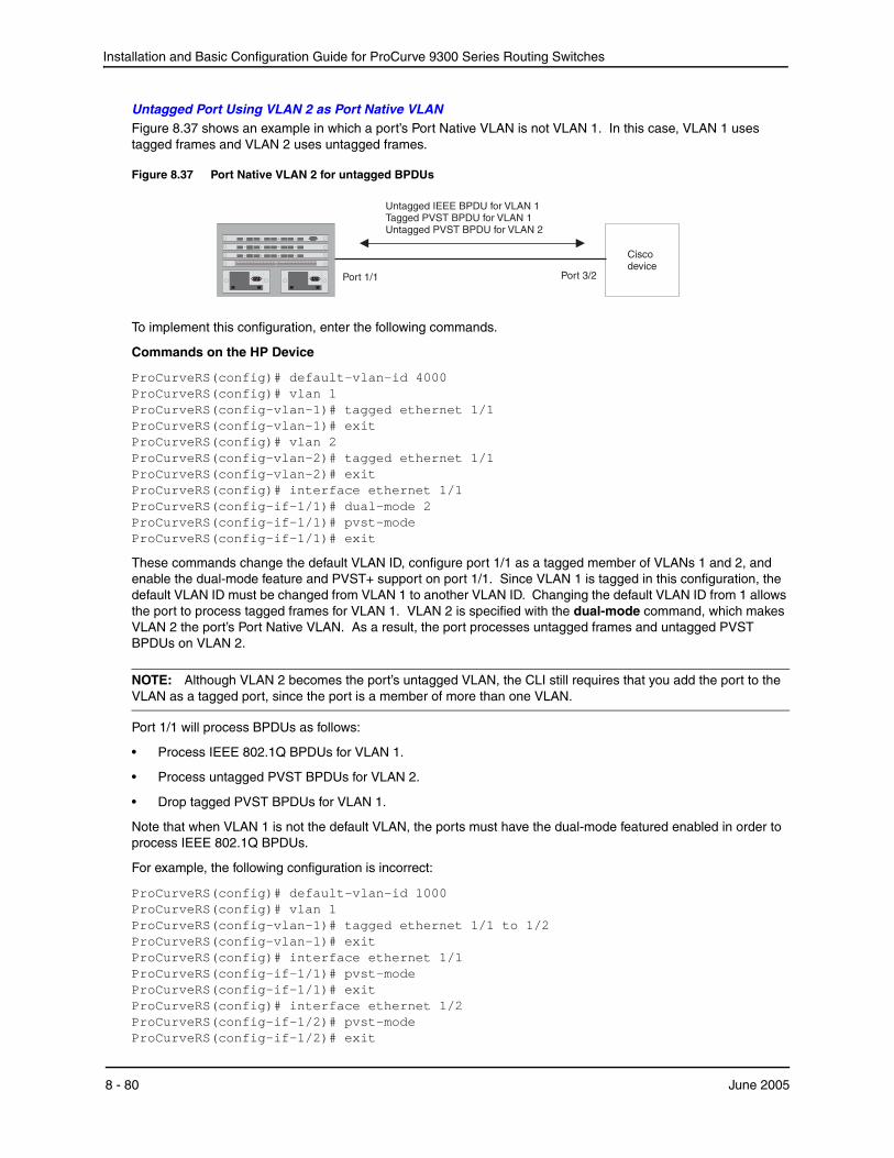
Installation and Basic Configuration Guide for ProCurve 9300 Series Routing Switches
Untagged Port Using VLAN 2 as Port Native VLANFigure 8.37 shows an example in which a port’s Port Native VLAN is not VLAN 1. In this case, VLAN 1 uses tagged frames and VLAN 2 uses untagged frames.
Figure 8.37 Port Native VLAN 2 for untagged BPDUs
Untagged IEEE BPDU for VLAN 1Tagged PVST BPDU for VLAN 1Untagged PVST BPDU for VLAN 2
Ciscodevice
Port 3/2Port 1/1
To implement this configuration, enter the following commands.
Commands on the HP Device
ProCurveRS(config)# default-vlan-id 4000 ProCurveRS(config)# vlan 1 ProCurveRS(config-vlan-1)# tagged ethernet 1/1 ProCurveRS(config-vlan-1)# exit ProCurveRS(config)# vlan 2 ProCurveRS(config-vlan-2)# tagged ethernet 1/1 ProCurveRS(config-vlan-2)# exit ProCurveRS(config)# interface ethernet 1/1 ProCurveRS(config-if-1/1)# dual-mode 2 ProCurveRS(config-if-1/1)# pvst-mode ProCurveRS(config-if-1/1)# exit
These commands change the default VLAN ID, configure port 1/1 as a tagged member of VLANs 1 and 2, and enable the dual-mode feature and PVST+ support on port 1/1. Since VLAN 1 is tagged in this configuration, the default VLAN ID must be changed from VLAN 1 to another VLAN ID. Changing the default VLAN ID from 1 allows the port to process tagged frames for VLAN 1. VLAN 2 is specified with the dual-mode command, which makes VLAN 2 the port’s Port Native VLAN. As a result, the port processes untagged frames and untagged PVST BPDUs on VLAN 2.
NOTE: Although VLAN 2 becomes the port’s untagged VLAN, the CLI still requires that you add the port to the VLAN as a tagged port, since the port is a member of more than one VLAN.
Port 1/1 will process BPDUs as follows:
• Process IEEE 802.1Q BPDUs for VLAN 1.
• Process untagged PVST BPDUs for VLAN 2.
• Drop tagged PVST BPDUs for VLAN 1.
Note that when VLAN 1 is not the default VLAN, the ports must have the dual-mode featured enabled in order to process IEEE 802.1Q BPDUs.
For example, the following configuration is incorrect:
ProCurveRS(config)# default-vlan-id 1000 ProCurveRS(config)# vlan 1 ProCurveRS(config-vlan-1)# tagged ethernet 1/1 to 1/2 ProCurveRS(config-vlan-1)# exit ProCurveRS(config)# interface ethernet 1/1 ProCurveRS(config-if-1/1)# pvst-mode ProCurveRS(config-if-1/1)# exit ProCurveRS(config)# interface ethernet 1/2 ProCurveRS(config-if-1/2)# pvst-mode ProCurveRS(config-if-1/2)# exit
8 - 80 June 2005
Configuring Spanning Tree Protocol (STP) and Advanced STP Features
In the configuration above, all PVST BPDUs associated with VLAN 1 would be discarded. Since IEEE BPDUs associated with VLAN 1 are untagged, they are discarded because the ports in VLAN 1 are tagged. Effectively, the BPDUs are never processed by the Spanning Tree Protocol. STP assumes that there is no better bridge on the network and sets the ports to FORWARDING. This could cause a Layer 2 loop.
The following configuration is correct:
ProCurveRS(config)# default-vlan-id 1000 ProCurveRS(config)# vlan 1 ProCurveRS(config-vlan-1)# tagged ethernet 1/1 to 1/2 ProCurveRS(config-vlan-1)# exit ProCurveRS(config)# interface ethernet 1/1 ProCurveRS(config-if-1/1)# pvst-mode ProCurveRS(config-if-1/1)# dual-mode ProCurveRS(config-if-1/1)# exit ProCurveRS(config)# interface ethernet 1/2 ProCurveRS(config-if-1/2)# pvst-mode ProCurveRS(config-if-1/2)# dual-mode ProCurveRS(config-if-1/2)# exit
Setting the ports as dual-mode ensures that the untagged IEEE 802.1Q BPDUs reach the VLAN 1 instance.
PVST/PVST+ Compatibility – Earlier Than 07.6.01bHP devices that are configured to support a separate spanning tree in each port-based VLAN can interoperate with Cisco devices that are running Per VLAN Spanning Tree (PVST) or PVST+, Cisco proprietary STP implementations that support separate spanning trees in each port-based VLAN.
An HP device configured to run a separate spanning tree in each port-based VLAN automatically enables PVST/PVST+ support on a port if that port receives an STP BPDU with PVST/PVST+ format. You also can enable PVST/PVST+ support statically as well as display PVST/PVST+ information for each port.
The information in this section is for reference. If you are running PVST/PVST+ on the Cisco devices and the default support for separate spanning trees in each VLAN on the HP devices, then no configuration is necessary for the devices to share spanning tree information.
NOTE: If you plan to use the PVST/PVST+ support, do not use VLAN 1. PVST+ uses VLAN 1 as a single STP broadcast domain and thus uses a different BPDU format than for other VLANs.
PVST
Each spanning tree (that is, each instance of STP) has one device called the root bridge. The root bridge is the control point for the spanning tree, and sends STP status and topology change information to the other devices in the spanning tree by sending BPDUs to the other devices. The other devices forward the BPDUs as needed.
The format of an STP BPDU differs depending on whether it is a Cisco PVST BPDU or an HP BPDU. HP and Cisco devices also can support single STP BPDUs, which use another format.
• An HP device configured with a separate spanning tree in each VLAN sends BPDUs in standard IEEE 802.1D format, but includes a proprietary four-byte tag. The tag identifies the VLAN the BPDU is for.
• A Cisco device configured for PVST sends the BPDUs to multicast MAC address 01-00-0C-CC-CC-CD. If the device is configured for PVST+, then the device sends BPDUs for all VLANs except VLAN 1 to 01-00-0C-CC-CC-CD. The device sends BPDUs in VLAN 1 to 01-80-C2-00-00-00, the single STP address (see below and “PVST+”).
• An HP device configured for single STP (IEEE 802.1Q) sends untagged BPDUs to the well-known STP MAC address 01-80-C2-00-00-00.
NOTE: Cisco devices can be configured to interoperate with devices that support IEEE 802.1Q single STP, but the devices cannot be configured to run single STP.
June 2005 8 - 81
Installation and Basic Configuration Guide for ProCurve 9300 Series Routing Switches
HP’s PVST support enables HP and Cisco devices that have separate spanning trees in each VLAN to interoperate. The HP PVST support is automatically enabled when a port receives a PVST BPDU and does not require configuration on the HP or Cisco device.
When PVST is enabled on an HP port, that port sends BPDUs in PVST format instead of HP’s spanning tree format.
PVST+
HP devices and Cisco devices support separate spanning trees on an individual port-based VLAN basis. However, until the IEEE standard for multiple spanning trees is finalized, vendors are using different methods to support multiple spanning trees within their own products. PVST+ is an extension to PVST that enables a Cisco device to interoperate with other devices that are running a single spanning tree (IEEE 802.1Q) while still running a separate spanning tree in each VLAN.
PVST+ uses 802.1Q single STP BPDUs on VLAN 1 and PVST BPDUs (which have a proprietary format) for other VLANs. In this case, the Cisco device uses devices running 802.1Q as tunnels for PVST (non-802.1Q) traffic. The 802.1Q single STP BPDUs are addressed to the well-known STP MAC address 01-80-C2-00-00-00. The PVST BPDUs for the other VLANs are addressed to multicast address 01-00-0C-CC-CC-CD.
The PVST+ method can require manual configuration of STP parameters on the 802.1Q devices to ensure that traffic for the PVST VLANs is not blocked. In addition, the opportunities to adjust STP parameters to load balance traffic on a VLAN basis are limited when using PVST+.
Using HP Single STP with Cisco PVST+Since HP’s single STP feature complies with IEEE 802.1Q (the single STP specification), you also can use an HP device running single STP to interoperate with a Cisco device running PVST+. When you enable single STP on an HP device, the PVST compatibility feature is not enabled, even if a port receives a PVST BPDU.
Enabling PVST/PVST+ Statically
PVST/PVST+ support is automatically enabled on a port if the port receives a BPDU in PVST/PVST+ format. However, you can statically enable PVST/PVST+ support on a port if desired. In this case, the support is enabled immediately and support for HP tagged BPDUs is disabled at the same time. To enable the PVST/PVST+ support, use the following CLI method.
NOTE: When PVST/PVST+ support is enabled on a port, support for HP BPDUs is disabled.
USING THE CLI
To enable PVST/PVST+ support on a port, enter commands such as the following:
ProCurveRS(config)# interface ethernet 1/1 ProCurveRS(config-if-1/1)# pvst-mode
Syntax: [no] pvst-mode
NOTE: If you disable PVST/PVST+ support, the software still automatically enables PVST/PVST+ support if the port receives an STP BPDU with PVST/PVST+ format.
USING THE WEB MANAGEMENT INTERFACE
You cannot enable PVST support using the Web management interface.
Displaying PVST Information
To display PVST information, use the following CLI method.
USING THE CLI
To display PVST information for ports on an HP device, enter the following command at any level of the CLI:
ProCurveRS(config)# show span pvst-mode
8 - 82 June 2005
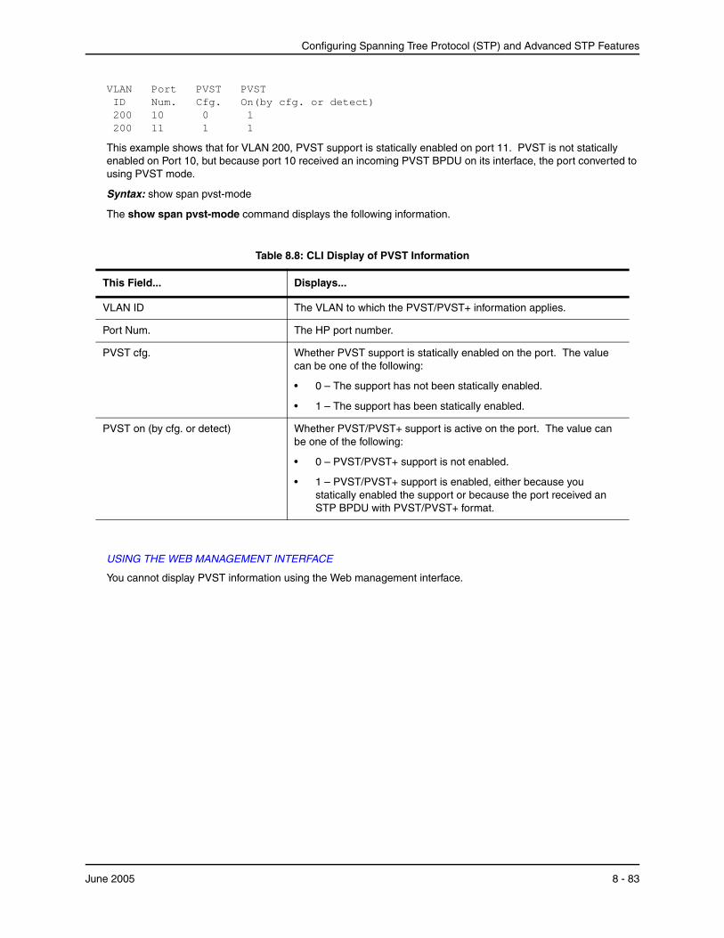
Configuring Spanning Tree Protocol (STP) and Advanced STP Features
VLAN Port PVST PVST ID Num. Cfg. On(by cfg. or detect) 200 10 0 1 200 11 1 1
This example shows that for VLAN 200, PVST support is statically enabled on port 11. PVST is not statically enabled on Port 10, but because port 10 received an incoming PVST BPDU on its interface, the port converted to using PVST mode.
Syntax: show span pvst-mode
The show span pvst-mode command displays the following information.
Table 8.8: CLI Display of PVST Information
This Field... Displays...
VLAN ID The VLAN to which the PVST/PVST+ information applies.
Port Num. The HP port number.
PVST cfg. Whether PVST support is statically enabled on the port. The value can be one of the following:
• 0 – The support has not been statically enabled.
• 1 – The support has been statically enabled.
PVST on (by cfg. or detect) Whether PVST/PVST+ support is active on the port. The value can be one of the following:
• 0 – PVST/PVST+ support is not enabled.
• 1 – PVST/PVST+ support is enabled, either because you statically enabled the support or because the port received an STP BPDU with PVST/PVST+ format.
USING THE WEB MANAGEMENT INTERFACE
You cannot display PVST information using the Web management interface.
June 2005 8 - 83

Installation and Basic Configuration Guide for ProCurve 9300 Series Routing Switches
8 - 84 June 2005
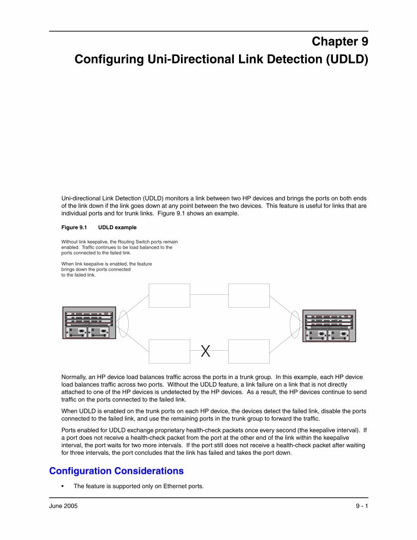
Chapter 9Configuring Uni-Directional Link Detection (UDLD)
Uni-directional Link Detection (UDLD) monitors a link between two HP devices and brings the ports on both ends of the link down if the link goes down at any point between the two devices. This feature is useful for links that are individual ports and for trunk links. Figure 9.1 shows an example.
Figure 9.1 UDLD example
X
Without link keepalive, the Routing Switch ports remainenabled. Traffic continues to be load balanced to theports connected to the failed link.
When link keepalive is enabled, the featurebrings down the ports connectedto the failed link.
Link
Activity
1 3 6 7 8542
Pwr
Link
Activity
Link
Activity
Link
Activity
3 542Link
Activity
61 7 8Link
Activity
Link
Activity
Link
Activity
1 2 3 4 5 6 7 8 9 10 11 12 13 14 15 16 17 18 19 20 21 22 23 24
3 542Link
Activity
61 7 8Link
Activity
Link
Activity
Link
Activity
Link
Activity
1 3 6 7 8542
Pwr
Link
Activity
Link
Activity
Link
Activity
3 542Link
Activity
61 7 8Link
Activity
Link
Activity
Link
Activity
1 2 3 4 5 6 7 8 9 10 11 12 13 14 15 16 17 18 19 20 21 22 23 24
3 542Link
Activity
61 7 8Link
Activity
Link
Activity
Link
Activity
Normally, an HP device load balances traffic across the ports in a trunk group. In this example, each HP device load balances traffic across two ports. Without the UDLD feature, a link failure on a link that is not directly attached to one of the HP devices is undetected by the HP devices. As a result, the HP devices continue to send traffic on the ports connected to the failed link.
When UDLD is enabled on the trunk ports on each HP device, the devices detect the failed link, disable the ports connected to the failed link, and use the remaining ports in the trunk group to forward the traffic.
Ports enabled for UDLD exchange proprietary health-check packets once every second (the keepalive interval). If a port does not receive a health-check packet from the port at the other end of the link within the keepalive interval, the port waits for two more intervals. If the port still does not receive a health-check packet after waiting for three intervals, the port concludes that the link has failed and takes the port down.
Configuration Considerations• The feature is supported only on Ethernet ports.
June 2005 9 - 1
Installation and Basic Configuration Guide for ProCurve 9300 Series Routing Switches
• To configure UDLD on a trunk group, you must configure the feature on each port of the group individually. Configuring UDLD on a trunk group’s primary port enables the feature on that port only.
• Dynamic trunking is not supported. If you want to configure a trunk group that contains ports on which UDLD is enabled, you must remove the UDLD configuration from the ports. After you create the trunk group, you can re-add the UDLD configuration.
Configuring UDLDTo enable UDLD on a port, enter a command such as the following at the global CONFIG level of the CLI:
ProCurveRS(config)# link-keepalive ethernet 1/1
Syntax: [no] link-keepalive ethernet <portnum> [ethernet <portnum>]
To enable the feature on a trunk group, enter commands such as the following:
ProCurveRS(config)# link-keepalive ethernet 1/1 ethernet 1/2 ProCurveRS(config)# link-keepalive ethernet 1/3 ethernet 1/4
These commands enable UDLD on ports 1/1 – 1/4. You can specify up to two ports on the same command line.
Changing the Keepalive IntervalBy default, ports enabled for UDLD send a link health-check packet once every 500 ms. You can change the interval to a value from 1 – 60, where 1 is 100 ms, 2 is 200 ms, and so on. To change the interval, enter a command such as the following:
ProCurveRS(config)# link-keepalive interval 3
Syntax: [no] link-keepalive interval <num>
The <num> parameter specifies how often the ports send a UDLD packet. You can specify from 1 – 60, in 100 ms increments. The default is 5 (500 ms).
Changing the Keepalive RetriesBy default, a port waits one second to receive a health-check reply packet from the port at the other end of the link. If the port does not receive a reply, the port tries four more times by sending up to four more health-check packets. If the port still does not receive a reply after the maximum number of retries, the port goes down.
You can change the maximum number of keepalive attempts to a value from 3 – 10. To change the maximum number of attempts, enter a command such as the following:
ProCurveRS(config)# link-keepalive retries 4
Syntax: [no] link-keepalive retries <num>
The <num> parameter specifies the maximum number of times the port will try the health check. You can specify a value from 3 – 10. The default is 5.
UDLD for Tagged PortsThe default implementation of UDLD sends the packets untagged, even across tagged ports. If the untagged UDLD packet is received by a third-party switch, that switch may reject the packet. As a result, UDLD may be limited only to HP devices, since UDLD may not function on third-party switches.
Beginning with Enterprise software release 07.6.06, you can configure ports to send out UDLD control packets that are tagged with a specific VLAN ID as tagged UDLD control packets. The enhancement also allows third party switches to receive the control packets that are tagged with the specified VLAN.
To allow ports to receive and send UDLD control packets tagged with a specific VLAN ID, enter commands such as the following:
ProCurveRS(config)# link-keepalive ethernet 1/18 vlan 22
9 - 2 June 2005
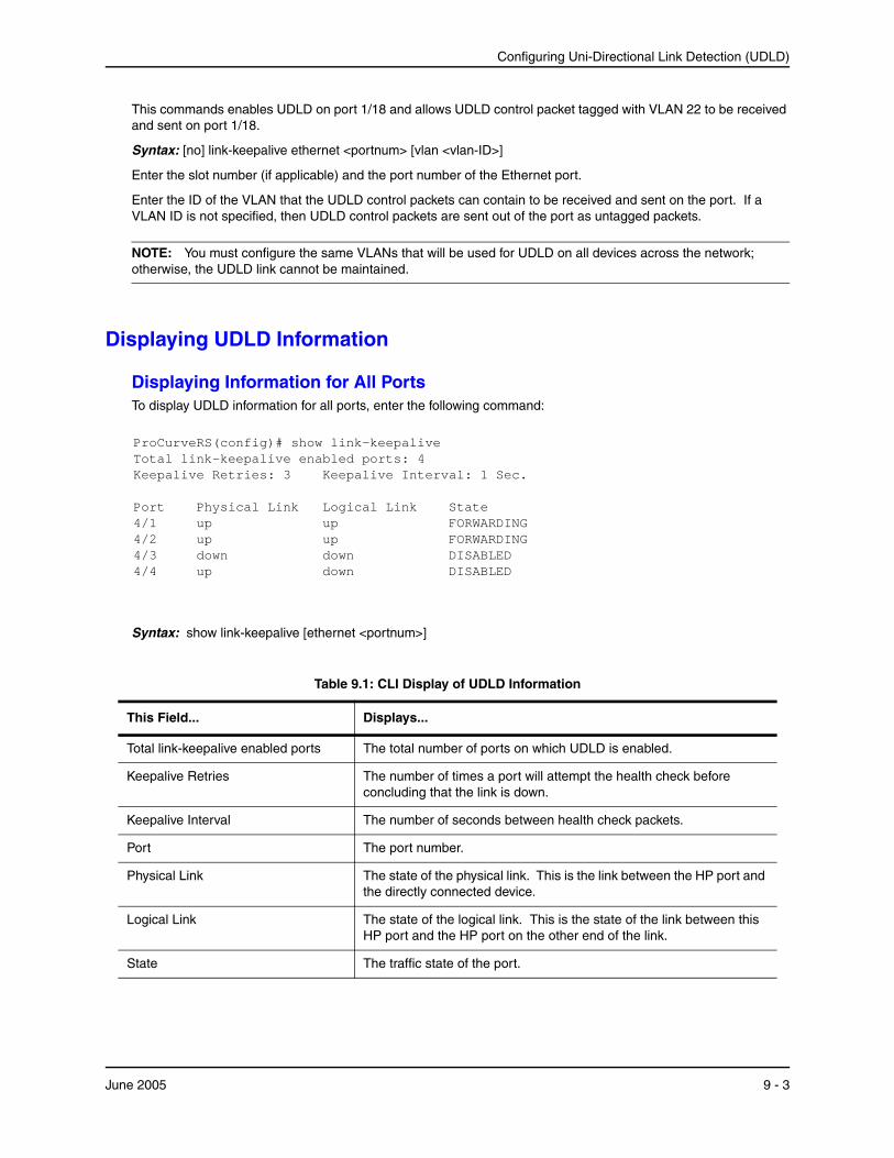
Configuring Uni-Directional Link Detection (UDLD)
This commands enables UDLD on port 1/18 and allows UDLD control packet tagged with VLAN 22 to be received and sent on port 1/18.
Syntax: [no] link-keepalive ethernet <portnum> [vlan <vlan-ID>]
Enter the slot number (if applicable) and the port number of the Ethernet port.
Enter the ID of the VLAN that the UDLD control packets can contain to be received and sent on the port. If a VLAN ID is not specified, then UDLD control packets are sent out of the port as untagged packets.
NOTE: You must configure the same VLANs that will be used for UDLD on all devices across the network; otherwise, the UDLD link cannot be maintained.
Displaying UDLD Information
Displaying Information for All PortsTo display UDLD information for all ports, enter the following command:
ProCurveRS(config)# show link-keepalive Total link-keepalive enabled ports: 4 Keepalive Retries: 3 Keepalive Interval: 1 Sec. Port Physical Link Logical Link State 4/1 up up FORWARDING 4/2 up up FORWARDING 4/3 down down DISABLED 4/4 up down DISABLED
Syntax: show link-keepalive [ethernet <portnum>]
Table 9.1: CLI Display of UDLD Information
This Field... Displays...
Total link-keepalive enabled ports The total number of ports on which UDLD is enabled.
Keepalive Retries The number of times a port will attempt the health check before concluding that the link is down.
Keepalive Interval The number of seconds between health check packets.
Port The port number.
Physical Link The state of the physical link. This is the link between the HP port and the directly connected device.
Logical Link The state of the logical link. This is the state of the link between this HP port and the HP port on the other end of the link.
State The traffic state of the port.
June 2005 9 - 3
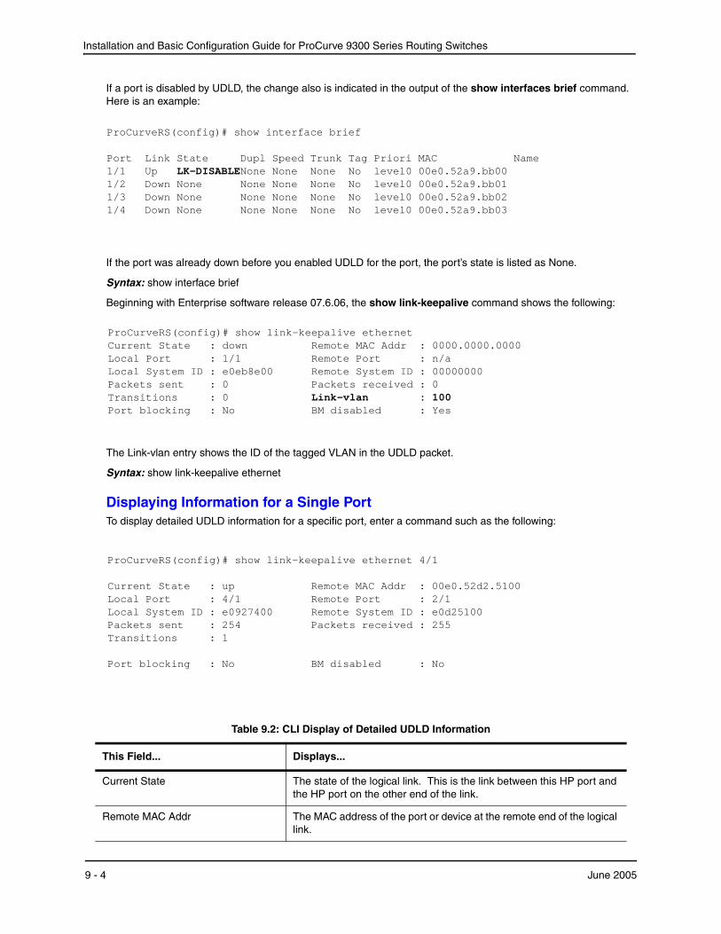
Installation and Basic Configuration Guide for ProCurve 9300 Series Routing Switches
If a port is disabled by UDLD, the change also is indicated in the output of the show interfaces brief command. Here is an example:
ProCurveRS(config)# show interface brief Port Link State Dupl Speed Trunk Tag Priori MAC Name 1/1 Up LK-DISABLENone None None No level0 00e0.52a9.bb00 1/2 Down None None None None No level0 00e0.52a9.bb01 1/3 Down None None None None No level0 00e0.52a9.bb02 1/4 Down None None None None No level0 00e0.52a9.bb03
If the port was already down before you enabled UDLD for the port, the port’s state is listed as None.
Syntax: show interface brief
Beginning with Enterprise software release 07.6.06, the show link-keepalive command shows the following:
ProCurveRS(config)# show link-keepalive ethernet Current State : down Remote MAC Addr : 0000.0000.0000 Local Port : 1/1 Remote Port : n/a Local System ID : e0eb8e00 Remote System ID : 00000000 Packets sent : 0 Packets received : 0 Transitions : 0 Link-vlan : 100 Port blocking : No BM disabled : Yes
The Link-vlan entry shows the ID of the tagged VLAN in the UDLD packet.
Syntax: show link-keepalive ethernet
Displaying Information for a Single PortTo display detailed UDLD information for a specific port, enter a command such as the following:
ProCurveRS(config)# show link-keepalive ethernet 4/1 Current State : up Remote MAC Addr : 00e0.52d2.5100 Local Port : 4/1 Remote Port : 2/1 Local System ID : e0927400 Remote System ID : e0d25100 Packets sent : 254 Packets received : 255 Transitions : 1 Port blocking : No BM disabled : No
Table 9.2: CLI Display of Detailed UDLD Information
This Field... Displays...
Current State The state of the logical link. This is the link between this HP port and the HP port on the other end of the link.
Remote MAC Addr The MAC address of the port or device at the remote end of the logical link.
9 - 4 June 2005
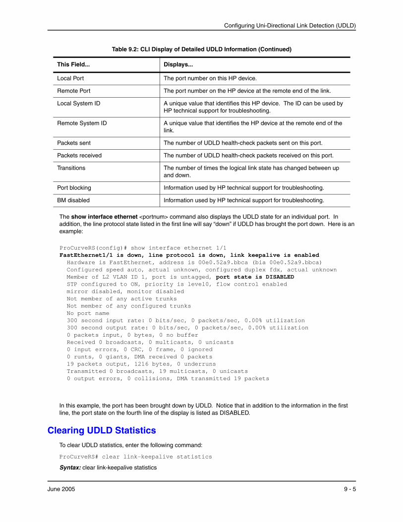
Configuring Uni-Directional Link Detection (UDLD)
The show interface ethernet <portnum> command also displays the UDLD state for an individual port. In addition, the line protocol state listed in the first line will say “down” if UDLD has brought the port down. Here is an example:
ProCurveRS(config)# show interface ethernet 1/1 FastEthernet1/1 is down, line protocol is down, link keepalive is enabled Hardware is FastEthernet, address is 00e0.52a9.bbca (bia 00e0.52a9.bbca) Configured speed auto, actual unknown, configured duplex fdx, actual unknown Member of L2 VLAN ID 1, port is untagged, port state is DISABLED STP configured to ON, priority is level0, flow control enabled mirror disabled, monitor disabled Not member of any active trunks Not member of any configured trunks No port name 300 second input rate: 0 bits/sec, 0 packets/sec, 0.00% utilization 300 second output rate: 0 bits/sec, 0 packets/sec, 0.00% utilization 0 packets input, 0 bytes, 0 no buffer Received 0 broadcasts, 0 multicasts, 0 unicasts 0 input errors, 0 CRC, 0 frame, 0 ignored 0 runts, 0 giants, DMA received 0 packets 19 packets output, 1216 bytes, 0 underruns Transmitted 0 broadcasts, 19 multicasts, 0 unicasts 0 output errors, 0 collisions, DMA transmitted 19 packets
In this example, the port has been brought down by UDLD. Notice that in addition to the information in the first line, the port state on the fourth line of the display is listed as DISABLED.
Clearing UDLD StatisticsTo clear UDLD statistics, enter the following command:
ProCurveRS# clear link-keepalive statistics
Syntax: clear link-keepalive statistics
Local Port The port number on this HP device.
Remote Port The port number on the HP device at the remote end of the link.
Local System ID A unique value that identifies this HP device. The ID can be used by HP technical support for troubleshooting.
Remote System ID A unique value that identifies the HP device at the remote end of the link.
Packets sent The number of UDLD health-check packets sent on this port.
Packets received The number of UDLD health-check packets received on this port.
Transitions The number of times the logical link state has changed between up and down.
Port blocking Information used by HP technical support for troubleshooting.
BM disabled Information used by HP technical support for troubleshooting.
Table 9.2: CLI Display of Detailed UDLD Information (Continued)
This Field... Displays...
June 2005 9 - 5

Installation and Basic Configuration Guide for ProCurve 9300 Series Routing Switches
This command clears the Packets sent, Packets received, and Transitions counters in the show link keepalive ethernet <portnum> display.
9 - 6 June 2005
Chapter 10Configuring Metro Features
This chapter describes the following Metro features:
• Topology groups – A topology group enables you to control the Layer 2 protocol configuration and Layer 2 state of a set of ports in multiple VLANs based on the configuration and states of those ports in a single master VLAN. One instance of the Layer 2 protocol controls all the VLANs. See “Topology Groups”.
• Metro Ring Protocol – MRP is an alternative to STP that provides Layer 2 redundancy and sub-second failover in ring topologies. See “Metro Ring Protocol (MRP)” on page 10-5.
• Virtual Switch Redundancy Protocol (VSRP) – VSRP is an alternative to STP that provides Layer 2 and Layer 3 redundancy and sub-second failover in mesh topologies. See “Virtual Switch Redundancy Protocol (VSRP)” on page 10-21.
You can use these features individually or in combination to provide fast, reliable, and easy to configure Layer 2 connectivity in your Metro network.
Topology GroupsA topology group is a named set of VLANs that share a Layer 2 topology. Topology groups simplify configuration and enhance scalability of Layer 2 protocols by allowing you to run a single instance of a Layer 2 protocol on multiple VLANs.
You can use topology groups with the following Layer 2 protocols:
• STP
• MRP
• VSRP
• 802.1W
Topology groups simplify Layer 2 configuration and provide scalability by enabling you to use the same instance of a Layer 2 protocol for multiple VLANs. For example, if an HP device is deployed in a Metro network and provides forwarding for two MRP rings that each contain 128 VLANs, you can configure a topology group for each ring. If a link failure in a ring causes a topology change, the change is applied to all the VLANs in the ring’s topology group. Without topology groups, you would need to configure a separate ring for each VLAN.
June 2005 10 - 1
Installation and Basic Configuration Guide for ProCurve 9300 Series Routing Switches
NOTE: If you plan to use a configuration saved under an earlier software release and the configuration contains STP groups, the CLI converts the STP groups into topology groups when you save the configuration under software release 07.6.01b. For backward compatibility, you can still use the STP group commands. However, the CLI converts the commands into the topology group syntax. Likewise, the show stp-group command displays STP topology groups.
Master VLAN and Member VLANsEach topology group contains a master VLAN and can contain one or more member VLANs and VLAN groups.
• Master VLAN – The master VLAN contains the configuration information for the Layer 2 protocol. For example, if you plan to use the topology group for MRP, the topology group’s master VLAN contains the ring configuration information.
• Member VLANs – The member VLANs are additional VLANs that share ports with the master VLAN. The Layer 2 protocol settings for the ports in the master VLAN apply to the same ports in the member VLANs. A change to the master VLAN’s Layer 2 protocol configuration or Layer 2 topology affects all the member VLANs. Member VLANs do not independently run a Layer 2 protocol.
• Member VLAN groups – A VLAN group is a named set of VLANs. The VLANs within a VLAN group have the same ports and use the same values for other VLAN parameters.
When a Layer 2 topology change occurs on a port in the master VLAN, the same change is applied to that port in all the member VLANs that contain the port. For example, if you configure a topology group whose master VLAN contains ports 1/1 and 1/2, a Layer 2 state change on port 1/1 applies to port 1/1 in all the member VLANs that contain that port. However, the state change does not affect port 1/1 in VLANs that are not members of the topology group.
Control Ports and Free PortsA port that is in a topology group can be a control port or a free port.
• Control port – A control port is a port in the master VLAN, and is therefore controlled by the Layer 2 protocol configured in the master VLAN. The same port in all the member VLANs is controlled by the master VLAN’s Layer 2 protocol. Each member VLAN must contain all of the control ports and can contain additional ports.
• Free port – A free port is not controlled by the master VLAN’s Layer 2 protocol. The master VLAN can contain free ports. (In this case, the Layer 2 protocol is disabled on those ports.) In addition, any ports in the member VLANs that are not also in the master VLAN are free ports.
NOTE: Since free ports are not controlled by the master port’s Layer 2 protocol, they are assumed to always be in the Forwarding state.
Configuration Considerations• You can configure up to 256 topology groups. Each group can control up to 4096 VLANs. A VLAN cannot be
controlled by more than one topology group.
• You must configure the master VLAN and member VLANs or member VLAN groups before you configure the topology group.
• The topology group must contain a master VLAN and can also contain individual member VLANs, VLAN groups, or a combination of individual member VLANs and VLAN groups.
• Once you add a VLAN as a member of a topology group, all the Layer 2 protocol information on the VLAN is deleted.
10 - 2 June 2005
Configuring Metro Features
Configuring a Topology GroupTo configure a topology group, enter commands such as the following:
ProCurveRS(config)# topology-group 2 ProCurveRS(config-topo-group-2)# master-vlan 2 ProCurveRS(config-topo-group-2)# member-vlan 3 ProCurveRS(config-topo-group-2)# member-vlan 4 ProCurveRS(config-topo-group-2)# member-vlan 5 ProCurveRS(config-topo-group-2)# member-group 2
These commands create topology group 2 and add the following:
• Master VLAN 2
• Member VLANs 2, 3, and 4
• Member VLAN group 2
Syntax: [no] topology-group <group-id>
The <group-id> parameter specifies the topology group ID and can be from 1 – 256.
Syntax: [no] master-vlan <vlan-id>
This command adds the master VLAN. The VLAN must already be configured. Make sure all the Layer 2 protocol settings in the VLAN are correct for your configuration before you add the VLAN to the topology group. A topology group can have only one master VLAN.
NOTE: If you remove the master VLAN (by entering no master-vlan <vlan-id>), the software selects the next-highest numbered member VLAN as the new master VLAN. For example, if you remove master VLAN 2 from the example above, the CLI converts member VLAN 3 into the new master VLAN. The new master VLAN inherits the Layer 2 protocol settings of the older master VLAN.
NOTE: If you add a new master VLAN to a topology group that already has a master VLAN, the new master VLAN replaces the older master VLAN. All member VLANs and VLAN groups follow the Layer 2 protocol settings of the new master VLAN.
Syntax: [no] member-vlan <vlan-id>
The <vlan-id> parameter specifies a VLAN ID. The VLAN must already be configured.
Syntax: [no] member-group <num>
The <num> specifies a VLAN group ID. The VLAN group must already be configured.
NOTE: Once you add a VLAN or VLAN group as a member of a topology group, all the Layer 2 protocol configuration information for the VLAN or group is deleted. For example, if STP is configured on a VLAN and you add the VLAN to a topology group, the STP configuration is removed from the VLAN. Once you add the VLAN to a topology group, the VLAN uses the Layer 2 protocol settings of the master VLAN. If you remove a member VLAN or VLAN group from a topology group, you will need to reconfigure the Layer 2 protocol information in the VLAN or VLAN group.
Displaying Topology Group InformationThe following sections show how to display STP information and topology group information for VLANS.
June 2005 10 - 3

Installation and Basic Configuration Guide for ProCurve 9300 Series Routing Switches
Displaying STP Information
To display STP information for a VLAN, enter a command such as the following:
ProCurveRS(config)# show span vlan 4 VLAN 4 BPDU cam_index is 14344 and the Master DMA Are(HEX) 18 1A STP instance owned by VLAN 2
This example shows STP information for VLAN 4. The line shown in bold type indicates that the VLAN’s STP configuration is controlled by VLAN 2. This information indicates that VLAN 4 is a member of a topology group and VLAN 2 is the master VLAN in that topology group.
Displaying Topology Group Information
To display topology group information, enter the following command:
ProCurveRS(config)# show topology-group Topology Group 3 ================= master-vlan 2 member-vlan none Common control ports L2 protocol ethernet 1/1 MRP ethernet 1/2 MRP ethernet 1/5 VSRP ethernet 2/22 VSRP Per vlan free ports ethernet 2/3 Vlan 2 ethernet 2/4 Vlan 2 ethernet 2/11 Vlan 2 ethernet 2/12 Vlan 2
Syntax: show topology-group [<group-id>]
This display shows the following information.
Table 10.1: CLI Display of Topology Group Information
This Field... Displays...
master-vlan The master VLAN for the topology group. The settings for STP, MRP, or VSRP on the control ports in the master VLAN apply to all control ports in the member VLANs within the topology group.
member-vlan The member VLANs in the topology group.
Common control ports The master VLAN ports that are configured with Layer 2 protocol information. The Layer 2 protocol configuration and state of these ports in the master VLAN applies to the same port numbers in all the member VLANs.
L2 protocol The Layer 2 protocol configured on the control ports. The Layer 2 protocol can be one of the following:
• MRP
• STP
• VSRP
10 - 4 June 2005
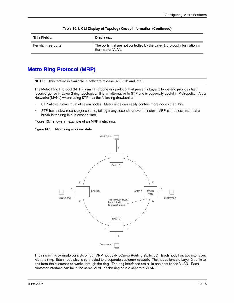
Configuring Metro Features
Metro Ring Protocol (MRP)
NOTE: This feature is available in software release 07.6.01b and later.
The Metro Ring Protocol (MRP) is an HP proprietary protocol that prevents Layer 2 loops and provides fast reconvergence in Layer 2 ring topologies. It is an alternative to STP and is especially useful in Metropolitan Area Networks (MANs) where using STP has the following drawbacks:
• STP allows a maximum of seven nodes. Metro rings can easily contain more nodes than this.
• STP has a slow reconvergence time, taking many seconds or even minutes. MRP can detect and heal a break in the ring in sub-second time.
Figure 10.1 shows an example of an MRP metro ring.
Figure 10.1 Metro ring – normal state
F
F
F
B
F
Switch D
F
F
Customer A
F
F
F
F
F
This interface blocksLayer 2 trafficto prevent a loop
Switch A
Switch B
MasterNode
Customer ACustomer A
Customer A
Switch C
The ring in this example consists of four MRP nodes (ProCurve Routing Switches). Each node has two interfaces with the ring. Each node also is connected to a separate customer network. The nodes forward Layer 2 traffic to and from the customer networks through the ring. The ring interfaces are all in one port-based VLAN. Each customer interface can be in the same VLAN as the ring or in a separate VLAN.
Per vlan free ports The ports that are not controlled by the Layer 2 protocol information in the master VLAN.
Table 10.1: CLI Display of Topology Group Information (Continued)
This Field... Displays...
June 2005 10 - 5
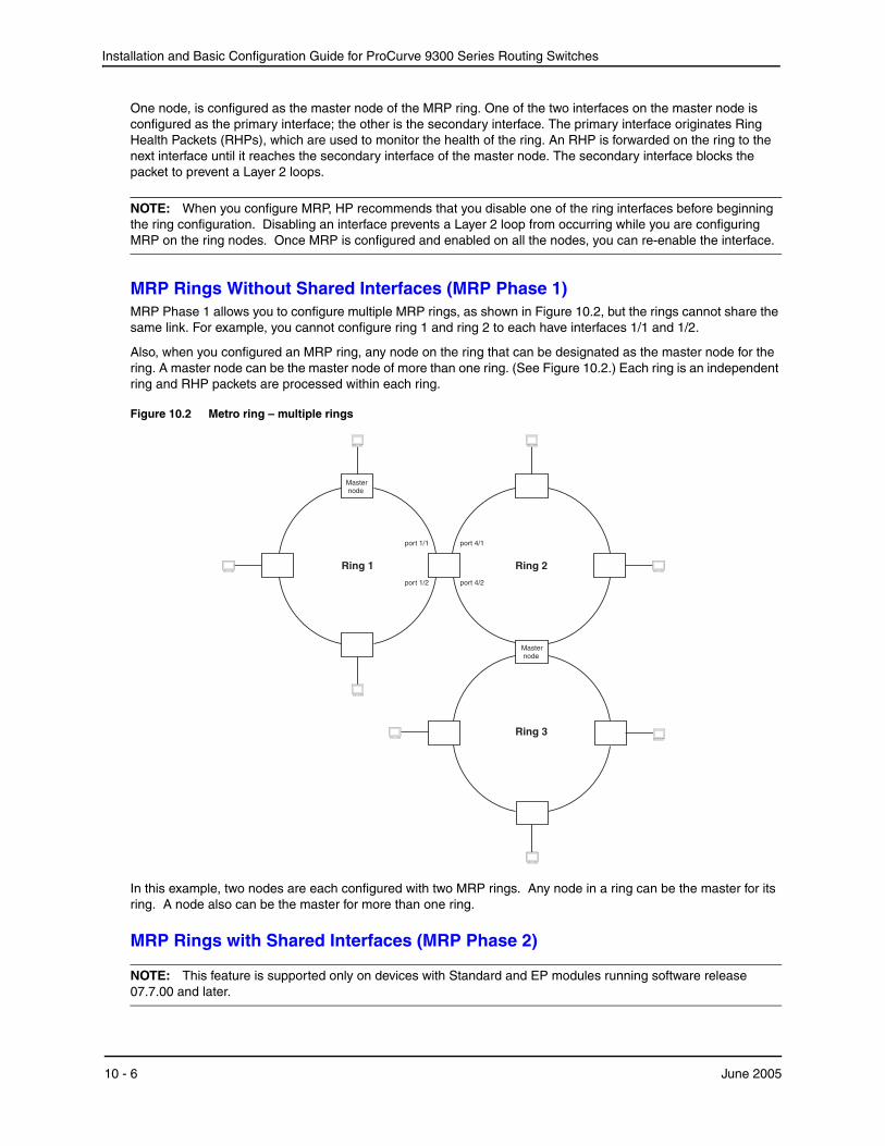
Installation and Basic Configuration Guide for ProCurve 9300 Series Routing Switches
One node, is configured as the master node of the MRP ring. One of the two interfaces on the master node is configured as the primary interface; the other is the secondary interface. The primary interface originates Ring Health Packets (RHPs), which are used to monitor the health of the ring. An RHP is forwarded on the ring to the next interface until it reaches the secondary interface of the master node. The secondary interface blocks the packet to prevent a Layer 2 loops.
NOTE: When you configure MRP, HP recommends that you disable one of the ring interfaces before beginning the ring configuration. Disabling an interface prevents a Layer 2 loop from occurring while you are configuring MRP on the ring nodes. Once MRP is configured and enabled on all the nodes, you can re-enable the interface.
MRP Rings Without Shared Interfaces (MRP Phase 1)MRP Phase 1 allows you to configure multiple MRP rings, as shown in Figure 10.2, but the rings cannot share the same link. For example, you cannot configure ring 1 and ring 2 to each have interfaces 1/1 and 1/2.
Also, when you configured an MRP ring, any node on the ring that can be designated as the master node for the ring. A master node can be the master node of more than one ring. (See Figure 10.2.) Each ring is an independent ring and RHP packets are processed within each ring.
Figure 10.2 Metro ring – multiple rings
Ring 3
Ring 2Ring 1
port 4/1
Masternode
port 1/2 port 4/2
port 1/1
Masternode
In this example, two nodes are each configured with two MRP rings. Any node in a ring can be the master for its ring. A node also can be the master for more than one ring.
MRP Rings with Shared Interfaces (MRP Phase 2)
NOTE: This feature is supported only on devices with Standard and EP modules running software release 07.7.00 and later.
10 - 6 June 2005
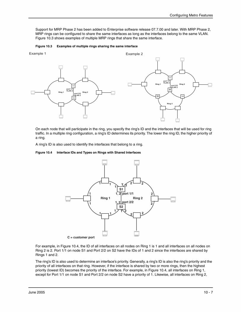
Configuring Metro Features
Support for MRP Phase 2 has been added to Enterprise software release 07.7.00 and later. With MRP Phase 2, MRP rings can be configured to share the same interfaces as long as the interfaces belong to the same VLAN. Figure 10.3 shows examples of multiple MRP rings that share the same interface.
Figure 10.3 Examples of multiple rings sharing the same interface
Ring 1port 2/2VLAN 2
Ring 2
port 1/1VLAN 2
S2
S1
Example 1 Example 2
Ring 1port 2/2VLAN 2
Ring 2
port 1/1VLAN 2
Ring 3
S1
S1S3 S4
S1S2
On each node that will participate in the ring, you specify the ring’s ID and the interfaces that will be used for ring traffic. In a multiple ring configuration, a ring’s ID determines its priority. The lower the ring ID, the higher priority of a ring.
A ring’s ID is also used to identify the interfaces that belong to a ring.
Figure 10.4 Interface IDs and Types on Rings with Shared Interfaces
Ring 1 Ring 21, 2
1, 2
11
1
1
1 11
1
22 2
2
2
222
T
T
S1
S2
C = customer port
port 1/1
port 2/2
For example, in Figure 10.4, the ID of all interfaces on all nodes on Ring 1 is 1 and all interfaces on all nodes on Ring 2 is 2. Port 1/1 on node S1 and Port 2/2 on S2 have the IDs of 1 and 2 since the interfaces are shared by Rings 1 and 2.
The ring’s ID is also used to determine an interface’s priority. Generally, a ring’s ID is also the ring’s priority and the priority of all interfaces on that ring. However, if the interface is shared by two or more rings, then the highest priority (lowest ID) becomes the priority of the interface. For example, in Figure 10.4, all interfaces on Ring 1, except for Port 1/1 on node S1 and Port 2/2 on node S2 have a priority of 1. Likewise, all interfaces on Ring 2,
June 2005 10 - 7

Installation and Basic Configuration Guide for ProCurve 9300 Series Routing Switches
except for Port 1/1 on node S1 and Port 2/2 on node S2 have a priority of 2. Port 1/1 on S1 and Port 2/2 on S2 have a priority of 1 since 1 is the highest priority (lowest ID) of the rings that share the interface.
If a node has interfaces that have different IDs, the interfaces that belong to the ring with the highest priority become regular ports. Those interfaces that do not belong to the ring with the highest priority become tunnel ports. In Figure 10.4, nodes S1 and S2 have interfaces that belong to Rings 1 and 2. Those interfaces with a priority of 1 are regular ports. The interfaces with a priority of 2 are the tunnel ports since they belong to Ring 2, which has a lower priority than Ring 1.
Selection of Master Node on Shared Interfaces
Allowing MRP rings to share interfaces limits the nodes that can be designated as the master node. Any node on an MRP ring that does not have a shared interface can be designated as the ring’s master node. However, if all nodes on the ring have shared interfaces, nodes that do not have tunnel ports can be designated as the master node of that ring. If none of the nodes meet these criteria, you must change the rings’ priorities by reconfiguring the rings’ ID.
In Figure 10.4, any of the nodes on Ring 1, even S1 or S2, can be a master node since none of its interfaces are tunnel ports. However in Ring 2, neither S1 nor S2 can be a master node since these nodes contain tunnel ports.
Ring InitializationThe ring shown in Figure 10.1 shows the port states in a fully initialized ring without any broken links. Figure 10.5 shows the initial state of the ring, when MRP is first enabled on the ring’s switches. All ring interfaces on the master node and member nodes begin in the Preforwarding state (PF).
Figure 10.5 Metro ring – initial state
F
PF
F
P F
Switch D
PF
PF
Customer A
PF
F
PF
PF
PF
Switch C Switch A
Switch B
MasterNode
Customer ACustomer A
Customer A
F
All ports start inPreforwarding state.
Primary port on Masternode sends RHP 1
MRP uses Ring Health Packets (RHPs) to monitor the health of the ring. An RHP is an MRP protocol packet. The source address is the MAC address of the master node and the destination MAC address is a protocol address for MRP. The Master node generates RHPs and sends them on the ring. The state of a ring port depends on the RHPs.
10 - 8 June 2005
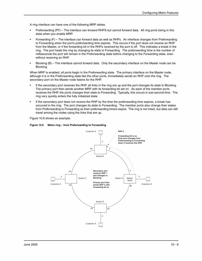
Configuring Metro Features
A ring interface can have one of the following MRP states:
• Preforwarding (PF) – The interface can forward RHPS but cannot forward data. All ring ports being in this state when you enable MRP.
• Forwarding (F) – The interface can forward data as well as RHPs. An interface changes from Preforwarding to Forwarding when the port’s preforwarding time expires. This occurs if the port does not receive an RHP from the Master, or if the forwarding bit in the RHPs received by the port is off. This indicates a break in the ring. The port heals the ring by changing its state to Forwarding. The preforwarding time is the number of milliseconds the port will remain in the Preforwarding state before changing to the Forwarding state, even without receiving an RHP.
• Blocking (B) – The interface cannot forward data. Only the secondary interface on the Master node can be Blocking.
When MRP is enabled, all ports begin in the Preforwarding state. The primary interface on the Master node, although it is in the Preforwarding state like the other ports, immediately sends an RHP onto the ring. The secondary port on the Master node listens for the RHP.
• If the secondary port receives the RHP, all links in the ring are up and the port changes its state to Blocking. The primary port then sends another MRP with its forwarding bit set on. As each of the member ports receives the RHP, the ports changes their state to Forwarding. Typically, this occurs in sub-second time. The ring very quickly enters the fully initialized state.
• If the secondary port does not receive the RHP by the time the preforwarding time expires, a break has occurred in the ring. The port changes its state to Forwarding. The member ports also change their states from Preforwarding to Forwarding as their preforwarding timers expire. The ring is not intact, but data can still travel among the nodes using the links that are up.
Figure 10.6 shows an example.
Figure 10.6 Metro ring – from Preforwarding to Forwarding
F
PF
F
B
Switch D
PF
PF
Customer A
F
F
RHP 2
Forwarding bit is on.Each port changes fromPreforwarding to Forwardingwhen it receives this RHP.
PF
PF
Switch C Switch A
Switch B
MasterNode
Customer ACustomer A
Customer A
F
Secondary portreceives RHP 1and changes toBlocking
Primary port thensends RHP 2 withforwarding bit on
F
June 2005 10 - 9

Installation and Basic Configuration Guide for ProCurve 9300 Series Routing Switches
Each RHP also has a sequence number. MRP can use the sequence number to determine the round-trip time for RHPs in the ring. See “Using MRP Diagnostics” on page 10-15.
Figure 10.7 shows an example of how RHP packets are processed normally in MRP rings with shared interfaces.
Figure 10.7 Flow of RHP packets on MRP Rings with Shared Interfaces
Ring 1 Ring 2
1,2
1,2
11
11
(primary interface) port 2/1
1
1
22
2
2
222
T
T
S1
S2
Master node Master node
(secondary interface) port 2/2 port 3/2 (secondary interface)
port 3/1 (primary interface)
2
1
1
= Ring 2 RHP packet= Ring 1 RHP packet
S4S3
Port 2/1 on Ring 1’s master node is the primary interface of the master node. The primary interface forwards an RHP packet on the ring. Since all the interfaces on Ring 1 are regular ports, the RHP packet is forwarded to all the interfaces until it reaches Port 2/2, the secondary interface of the master node. Port 2/2 then blocks the packet to complete the process.
On Ring 2, Port 3/1, is the primary interface of the master node. It sends an RHP packet on the ring. Since all ports on S4 are regular ports, the RHP packet is forwarded on those interfaces. When the packet reaches S2, the receiving interface is a tunnel port. The port compares the packet’s priority to its priority. Since the packet’s priority is the same as the tunnel port’s priority, the packet is forwarded up the link shared by Rings 1 and 2.
When the RHP packet reaches the interface on node S2 shared by Rings 1 and 2, the packet is forwarded since its priority is less than the interface’s priority. The packet continues to be forwarded to node S1 until it reaches the tunnel port on S1. That tunnel port determines that the RHP packet’s priority is equal to the port’s priority and forwards the packet. The RHP packet is forwarded to the remaining interfaces on Ring 2 until it reaches port 3/2, the secondary interface of the master node. Port 3/2 then blocks the packet to prevent a loop.
When the RHP packet from Ring 2 reached S2, it was also forwarded from S2 to S3 on Ring 1 since the port on S2 has a higher priority than the RHP packet. The packets is forwarded around Ring 1 until it reaches port 2/2, Ring 1’s the secondary port. The RHP packet is then blocked by that port.
How Ring Breaks Are Detected and HealedFigure 10.8 shows ring interface states following a link break. MRP quickly heals the ring and preserves connectivity among the customer networks.
10 - 10 June 2005
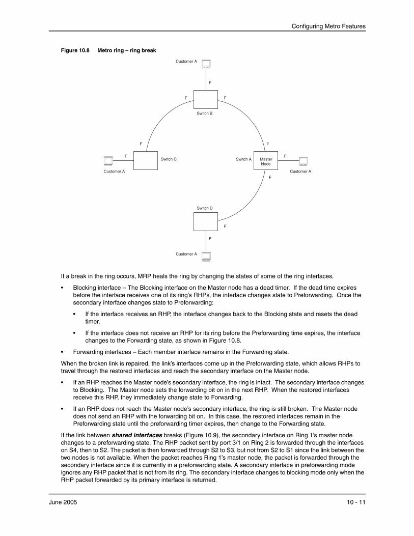
Configuring Metro Features
Figure 10.8 Metro ring – ring break
F
F
F
Switch D
F
Customer A
F
F
F
F
F
Switch C Switch A
Switch B
MasterNode
Customer ACustomer A
Customer A
F
If a break in the ring occurs, MRP heals the ring by changing the states of some of the ring interfaces.
• Blocking interface – The Blocking interface on the Master node has a dead timer. If the dead time expires before the interface receives one of its ring’s RHPs, the interface changes state to Preforwarding. Once the secondary interface changes state to Preforwarding:
• If the interface receives an RHP, the interface changes back to the Blocking state and resets the dead timer.
• If the interface does not receive an RHP for its ring before the Preforwarding time expires, the interface changes to the Forwarding state, as shown in Figure 10.8.
• Forwarding interfaces – Each member interface remains in the Forwarding state.
When the broken link is repaired, the link’s interfaces come up in the Preforwarding state, which allows RHPs to travel through the restored interfaces and reach the secondary interface on the Master node.
• If an RHP reaches the Master node’s secondary interface, the ring is intact. The secondary interface changes to Blocking. The Master node sets the forwarding bit on in the next RHP. When the restored interfaces receive this RHP, they immediately change state to Forwarding.
• If an RHP does not reach the Master node’s secondary interface, the ring is still broken. The Master node does not send an RHP with the forwarding bit on. In this case, the restored interfaces remain in the Preforwarding state until the preforwarding timer expires, then change to the Forwarding state.
If the link between shared interfaces breaks (Figure 10.9), the secondary interface on Ring 1’s master node changes to a preforwarding state. The RHP packet sent by port 3/1 on Ring 2 is forwarded through the interfaces on S4, then to S2. The packet is then forwarded through S2 to S3, but not from S2 to S1 since the link between the two nodes is not available. When the packet reaches Ring 1’s master node, the packet is forwarded through the secondary interface since it is currently in a preforwarding state. A secondary interface in preforwarding mode ignores any RHP packet that is not from its ring. The secondary interface changes to blocking mode only when the RHP packet forwarded by its primary interface is returned.
June 2005 10 - 11
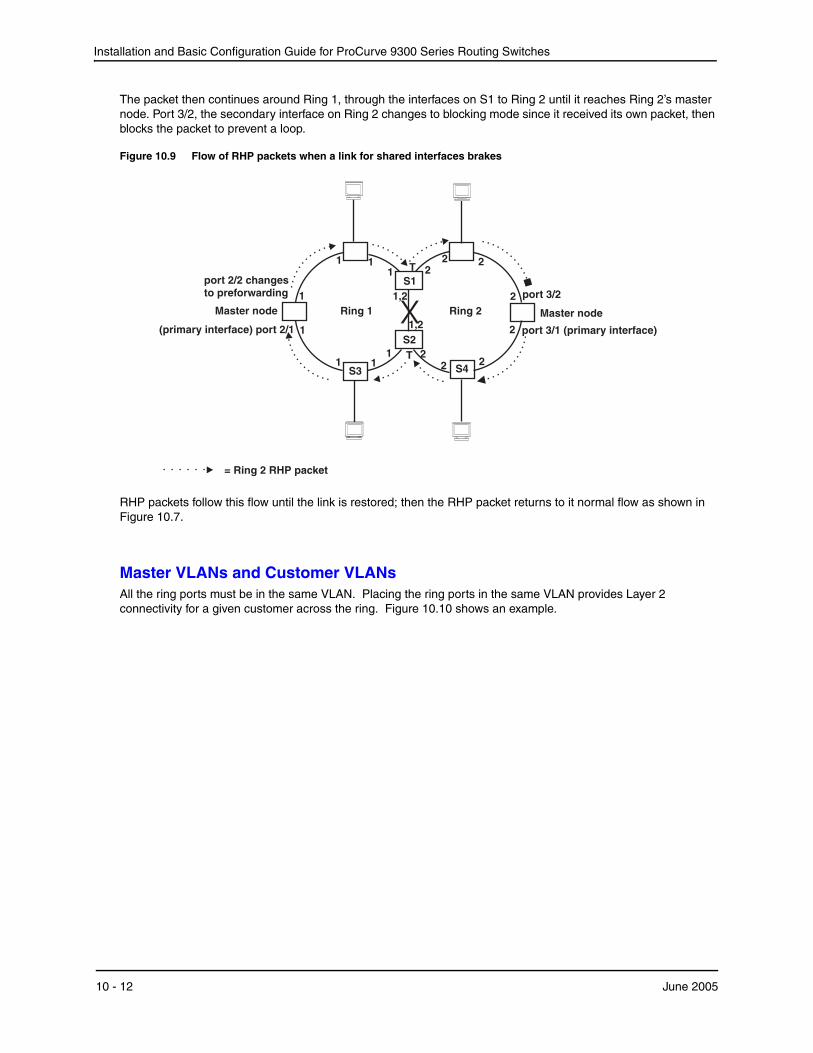
Installation and Basic Configuration Guide for ProCurve 9300 Series Routing Switches
The packet then continues around Ring 1, through the interfaces on S1 to Ring 2 until it reaches Ring 2’s master node. Port 3/2, the secondary interface on Ring 2 changes to blocking mode since it received its own packet, then blocks the packet to prevent a loop.
Figure 10.9 Flow of RHP packets when a link for shared interfaces brakes
Ring 1 Ring 21,2
1,2
11
11
(primary interface) port 2/1
1
1
22
2
2
222
T
T
S1
S2
Master node Master node
port 2/2 changesto preforwarding port 3/2
port 3/1 (primary interface)
2
1
1
= Ring 2 RHP packet
X
S3 S4
RHP packets follow this flow until the link is restored; then the RHP packet returns to it normal flow as shown in Figure 10.7.
Master VLANs and Customer VLANsAll the ring ports must be in the same VLAN. Placing the ring ports in the same VLAN provides Layer 2 connectivity for a given customer across the ring. Figure 10.10 shows an example.
10 - 12 June 2005
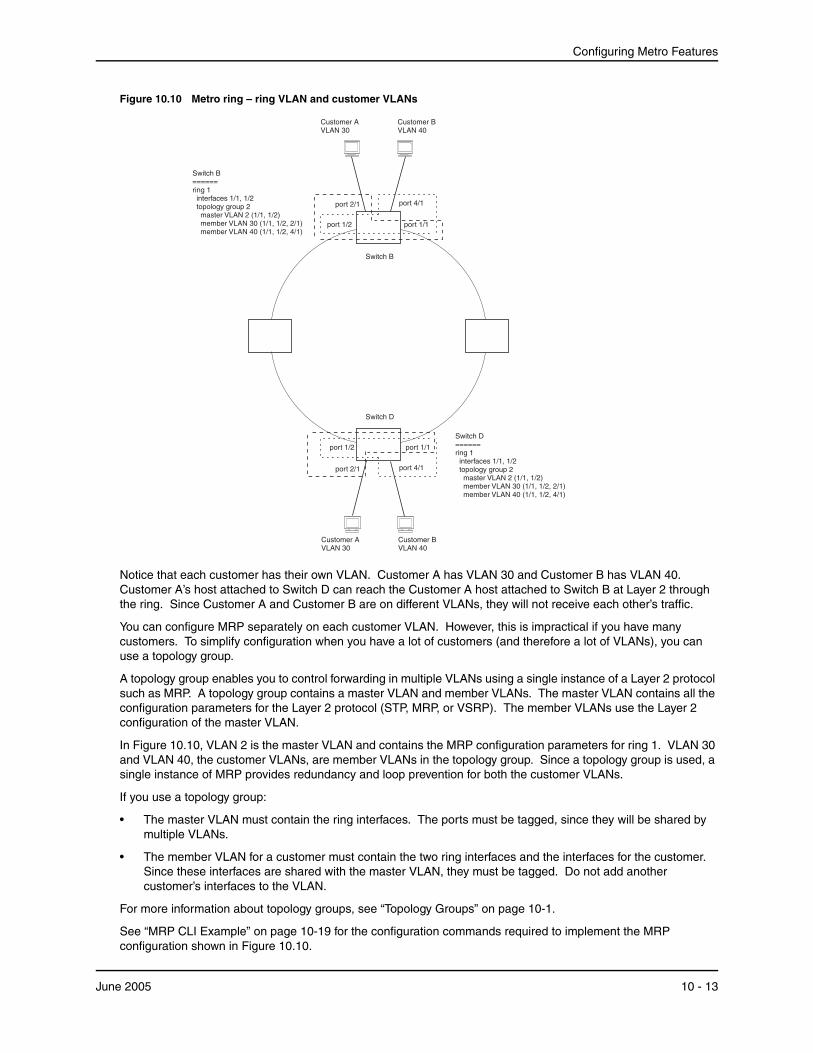
Configuring Metro Features
Figure 10.10 Metro ring – ring VLAN and customer VLANs
port 4/1
Switch D
port 1/1port 1/2
Switch B
Customer BVLAN 40
port 2/1
Customer AVLAN 30
Switch B======ring 1
interfaces 1/1, 1/2topology group 2
master VLAN 2 (1/1, 1/2)member VLAN 30 (1/1, 1/2, 2/1)member VLAN 40 (1/1, 1/2, 4/1)
port 4/1
port 1/1port 1/2
Customer BVLAN 40
port 2/1
Customer AVLAN 30
Switch D======ring 1
interfaces 1/1, 1/2topology group 2
master VLAN 2 (1/1, 1/2)member VLAN 30 (1/1, 1/2, 2/1)member VLAN 40 (1/1, 1/2, 4/1)
Notice that each customer has their own VLAN. Customer A has VLAN 30 and Customer B has VLAN 40. Customer A’s host attached to Switch D can reach the Customer A host attached to Switch B at Layer 2 through the ring. Since Customer A and Customer B are on different VLANs, they will not receive each other’s traffic.
You can configure MRP separately on each customer VLAN. However, this is impractical if you have many customers. To simplify configuration when you have a lot of customers (and therefore a lot of VLANs), you can use a topology group.
A topology group enables you to control forwarding in multiple VLANs using a single instance of a Layer 2 protocol such as MRP. A topology group contains a master VLAN and member VLANs. The master VLAN contains all the configuration parameters for the Layer 2 protocol (STP, MRP, or VSRP). The member VLANs use the Layer 2 configuration of the master VLAN.
In Figure 10.10, VLAN 2 is the master VLAN and contains the MRP configuration parameters for ring 1. VLAN 30 and VLAN 40, the customer VLANs, are member VLANs in the topology group. Since a topology group is used, a single instance of MRP provides redundancy and loop prevention for both the customer VLANs.
If you use a topology group:
• The master VLAN must contain the ring interfaces. The ports must be tagged, since they will be shared by multiple VLANs.
• The member VLAN for a customer must contain the two ring interfaces and the interfaces for the customer. Since these interfaces are shared with the master VLAN, they must be tagged. Do not add another customer’s interfaces to the VLAN.
For more information about topology groups, see “Topology Groups” on page 10-1.
See “MRP CLI Example” on page 10-19 for the configuration commands required to implement the MRP configuration shown in Figure 10.10.
June 2005 10 - 13

Installation and Basic Configuration Guide for ProCurve 9300 Series Routing Switches
Configuring MRPTo configure MRP, perform the following tasks. You need to perform the first task on only one of the nodes. Perform the remaining tasks on all the nodes.
• Disable one of the ring interfaces. This prevents a Layer 2 loop from occurring while you are configuring the devices for MRP.
• Add an MRP ring to a port-based VLAN. When you add a ring, the CLI changes to the configuration level for the ring, where you can perform the following tasks.
• Optionally, specify a name for the ring.
• On the master node only, enable the device to be the master for the ring. Each ring can have only one master node.
• Specify the MRP interfaces. Each device has two interfaces to an MRP ring.
• Optionally, change the hello time and the preforwarding time. These parameters control how quickly failover occurs following a change in the state of a link in the ring.
• Enable the ring.
• Optionally, add the ring’s VLAN to a topology group to add more VLANs to the ring. If you use a topology group, make sure you configure MRP on the group’s master VLAN. See “Topology Groups” on page 10-1.
• Re-enable the interface you disabled to prevent a Layer 2 loop. Once MRP is enabled, MRP will prevent the Layer 2 loop.
Adding an MRP Ring to a VLAN
To add an MRP ring to a VLAN, enter commands such as the following.
NOTE: If you plan to use a topology group to add VLANs to the ring, make sure you configure MRP on the topology group’s master VLAN.
ProCurveRS(config)# vlan 2 ProCurveRS(config-vlan-2)# metro-ring 1 ProCurveRS(config-vlan-2-mrp-1)# name CustomerA ProCurveRS(config-vlan-2-mrp-1)# master ProCurveRS(config-vlan-2-mrp-1)# ring-interface ethernet 1/1 ethernet 1/2 ProCurveRS(config-vlan-2-mrp-1)# enable
These commands configure an MRP ring on VLAN 2. The ring ID is 1, the ring name is CustomerA, and this node (this HP device) is the master for the ring. The ring interfaces are 1/1 and 1/2. Interface 1/1 is the primary interface and 1/2 is the secondary interface. The primary interface will initiate RHPs by default. The ring takes effect in VLAN 2.
To configure MRP rings with shared interfaces, enter commands such as the following:
ProCurveRS(config)# vlan 2 ProCurveRS(config-vlan-2)# metro-ring 1 ProCurveRS(config-vlan-2-mrp-1)# name CustomerA ProCurveRS(config-vlan-2-mrp-1)# ring-interface ethernet 1/1 ethernet 1/2 ProCurveRS(config-vlan-2-mrp-1)# enable ProCurveRS(config-vlan-2-mrp-1)# metro-ring 2 ProCurveRS(config-vlan-2-mrp-2)# name CustomerB ProCurveRS(config-vlan-2-mrp-2)# ring-interface ethernet 1/1 ethernet 1/2 ProCurveRS(config-vlan-2-mrp-1)# enable
Syntax: [no] metro-ring <ring-id>
The <ring-id> parameter specifies the ring ID and can be from 1 – 255. Configure the same ring ID on each of the nodes in the ring.
Syntax: [no] name <string>
10 - 14 June 2005
Configuring Metro Features
The <string> parameter specifies a name for the ring. The name is optional, but it can be up to 20 characters long and can include blank spaces. If you use a name that has blank spaces, enclose the name in double quotation marks (for example: “Customer A”).
Syntax: [no] master
Configures this node as the master node for the ring. Enter this command only on one node in the ring. The node is a member (non-master) node by default.
Syntax: [no] ring-interface ethernet <primary-if> ethernet <secondary-if>
The ethernet <primary-if> parameter specifies the primary interface. On the master node, the primary interface is the one that originates RHPs. Ring control traffic and Layer 2 data traffic will flow in the outward direction from this interface by default. On member nodes, the direction of traffic flow depends on the traffic direction selected by the master node. Therefore, on a member node, the order in which you enter the interfaces does not matter.
The ethernet <secondary-if> parameter specifies the secondary interface.
NOTE: To take advantage of every interface in a Metro network, you can configure another MRP ring and either configure a different Master node for the ring or reverse the configuration of the primary and secondary interfaces on the Master node. Configuring multiple rings enables you to use all the ports in the ring. The same port can forward traffic one ring while blocking traffic for another ring.
Syntax: [no] enable
The enable command enables the ring.
Changing the Hello and PreForwarding Times
You also can change the RHP hello time and preforwarding time. To do so, enter commands such as the following:
ProCurveRS(config-vlan-2-mrp-1)# hello-time 200 ProCurveRS(config-vlan-2-mrp-1)# preforwarding-time 400
These commands change the hello time to 200 ms and change the preforwarding time to 400 ms.
NOTE: The preforwarding time must be at least twice the value of the hello time and must be a multiple of the hello time.
Syntax: [no] hello-time <ms>
Syntax: [no] preforwarding-time <ms>
The <ms> specifies the number of milliseconds. For the hello time, you can specify from 100 – 1000 (one second). The default hello time is 100 ms. The preforwarding time can be from 200 – 5000 ms, but must be at least twice the value of the hello time and must be a multiple of the hello time. The default preforwarding time is 300 ms. A change to the hello time or preforwarding time takes effect as soon as you enter the command.
NOTE: You can use MRP ring diagnostics to determine whether you need to change the hello time and preforwarding time. See “Using MRP Diagnostics”.
Using MRP DiagnosticsThe MRP diagnostics feature calculates how long it takes for RHP packets to travel through the ring. When you enable MRP diagnostics, the software tracks RHP packets according to their sequence numbers and calculates how long it takes an RHP packet to travel one time through the entire ring. When you display the diagnostics, the CLI shows the average round-trip time for the RHP packets sent since you enabled diagnostics. The calculated results have a granularity of 1 microsecond.
Enabling MRP Diagnostics
To enable MRP diagnostics for a ring, enter the following command on the Master node, at the configuration level for the ring:
June 2005 10 - 15
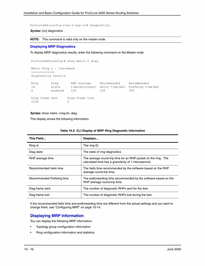
Installation and Basic Configuration Guide for ProCurve 9300 Series Routing Switches
ProCurveRS(config-vlan-2-mrp-1)# diagnostics
Syntax: [no] diagnostics
NOTE: This command is valid only on the master node.
Displaying MRP Diagnostics
To display MRP diagnostics results, enter the following command on the Master node:
ProCurveRS(config)# show metro 2 diag Metro Ring 2 - CustomerA ============= diagnostics results Ring Diag RHP average Recommended Recommended id state time(microsec) hello time(ms) Prefwing time(ms) 2 enabled 125 100 300 Diag frame sent Diag frame lost 1230 0
Syntax: show metro <ring-id> diag
This display shows the following information.
Table 10.2: CLI Display of MRP Ring Diagnostic Information
This Field... Displays...
Ring id The ring ID.
Diag state The state of ring diagnostics.
RHP average time The average round-trip time for an RHP packet on the ring. The calculated time has a granularity of 1 microsecond.
Recommended hello time The hello time recommended by the software based on the RHP average round-trip time.
Recommended Prefwing time The preforwarding time recommended by the software based on the RHP average round-trip time.
Diag frame sent The number of diagnostic RHPs sent for the test.
Diag frame lost The number of diagnostic RHPs lost during the test.
If the recommended hello time and preforwarding time are different from the actual settings and you want to change them, see “Configuring MRP” on page 10-14.
Displaying MRP InformationYou can display the following MRP information:
• Topology group configuration information
• Ring configuration information and statistics
10 - 16 June 2005
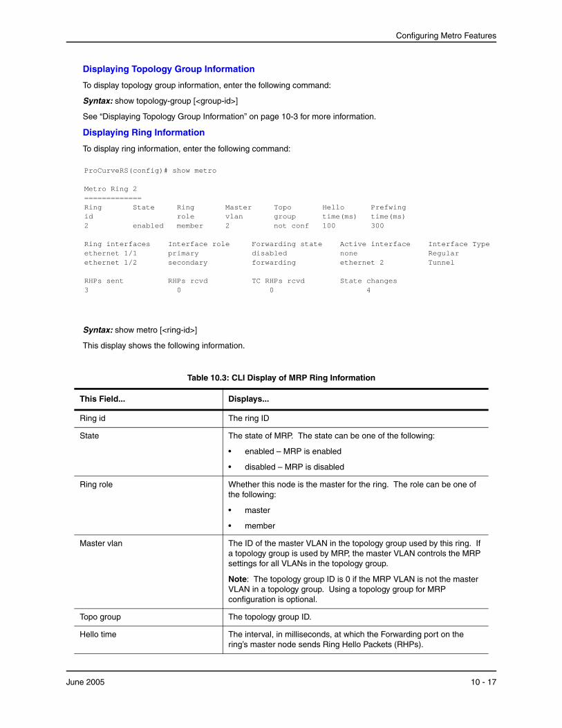
Configuring Metro Features
Displaying Topology Group Information
To display topology group information, enter the following command:
Syntax: show topology-group [<group-id>]
See “Displaying Topology Group Information” on page 10-3 for more information.
Displaying Ring Information
To display ring information, enter the following command:
ProCurveRS(config)# show metro Metro Ring 2 ============= Ring State Ring Master Topo Hello Prefwing id role vlan group time(ms) time(ms) 2 enabled member 2 not conf 100 300 Ring interfaces Interface role Forwarding state Active interface Interface Type ethernet 1/1 primary disabled none Regular ethernet 1/2 secondary forwarding ethernet 2 Tunnel RHPs sent RHPs rcvd TC RHPs rcvd State changes 3 0 0 4
Syntax: show metro [<ring-id>]
This display shows the following information.
Table 10.3: CLI Display of MRP Ring Information
This Field... Displays...
Ring id The ring ID
State The state of MRP. The state can be one of the following:
• enabled – MRP is enabled
• disabled – MRP is disabled
Ring role Whether this node is the master for the ring. The role can be one of the following:
• master
• member
Master vlan The ID of the master VLAN in the topology group used by this ring. If a topology group is used by MRP, the master VLAN controls the MRP settings for all VLANs in the topology group.
Note: The topology group ID is 0 if the MRP VLAN is not the master VLAN in a topology group. Using a topology group for MRP configuration is optional.
Topo group The topology group ID.
Hello time The interval, in milliseconds, at which the Forwarding port on the ring’s master node sends Ring Hello Packets (RHPs).
June 2005 10 - 17
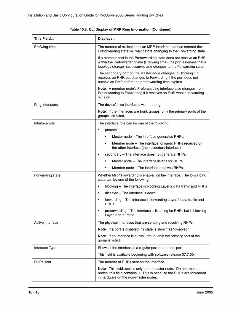
Installation and Basic Configuration Guide for ProCurve 9300 Series Routing Switches
Prefwing time The number of milliseconds an MRP interface that has entered the Preforwarding state will wait before changing to the Forwarding state.
If a member port in the Preforwarding state does not receive an RHP within the Preforwarding time (Prefwing time), the port assumes that a topology change has occurred and changes to the Forwarding state.
The secondary port on the Master node changes to Blocking if it receives an RHP, but changes to Forwarding if the port does not receive an RHP before the preforwarding time expires.
Note: A member node’s Preforwarding interface also changes from Preforwarding to Forwarding if it receives an RHP whose forwarding bit is on.
Ring interfaces The device’s two interfaces with the ring.
Note: If the interfaces are trunk groups, only the primary ports of the groups are listed.
Interface role The interface role can be one of the following:
• primary
• Master node – The interface generates RHPs.
• Member node – The interface forwards RHPs received on the other interface (the secondary interface).
• secondary – The interface does not generate RHPs.
• Master node – The interface listens for RHPs.
• Member node – The interface receives RHPs.
Forwarding state Whether MRP Forwarding is enabled on the interface. The forwarding state can be one of the following:
• blocking – The interface is blocking Layer 2 data traffic and RHPs
• disabled – The interface is down
• forwarding – The interface is forwarding Layer 2 data traffic and RHPs
• preforwarding – The interface is listening for RHPs but is blocking Layer 2 data traffic
Active interface The physical interfaces that are sending and receiving RHPs.
Note: If a port is disabled, its state is shown as “disabled”.
Note: If an interface is a trunk group, only the primary port of the group is listed.
Interface Type Shows if the interface is a regular port or a tunnel port.
This field is available beginning with software release 07.7.00.
RHPs sent The number of RHPs sent on the interface.
Note: This field applies only to the master node. On non-master nodes, this field contains 0. This is because the RHPs are forwarded in hardware on the non-master nodes.
Table 10.3: CLI Display of MRP Ring Information (Continued)
This Field... Displays...
10 - 18 June 2005
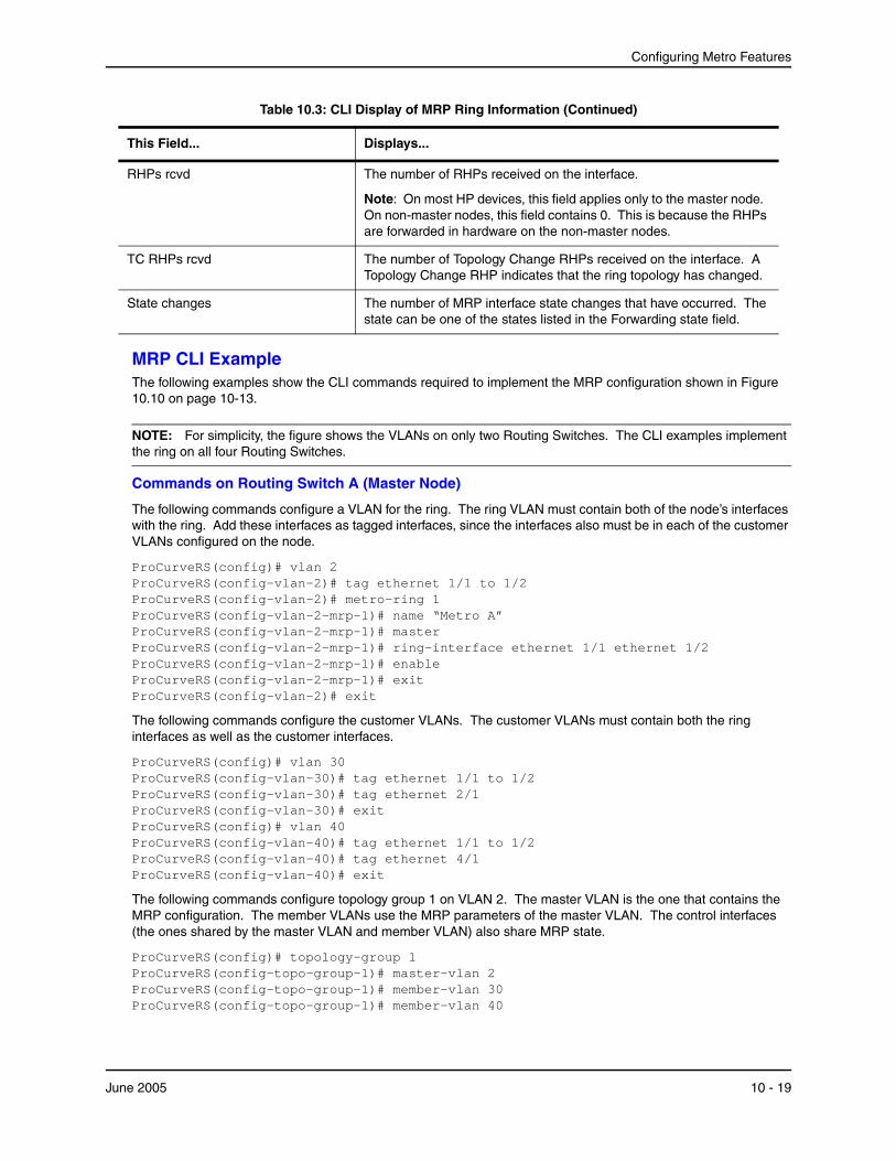
Configuring Metro Features
MRP CLI ExampleThe following examples show the CLI commands required to implement the MRP configuration shown in Figure 10.10 on page 10-13.
NOTE: For simplicity, the figure shows the VLANs on only two Routing Switches. The CLI examples implement the ring on all four Routing Switches.
Commands on Routing Switch A (Master Node)
The following commands configure a VLAN for the ring. The ring VLAN must contain both of the node’s interfaces with the ring. Add these interfaces as tagged interfaces, since the interfaces also must be in each of the customer VLANs configured on the node.
ProCurveRS(config)# vlan 2 ProCurveRS(config-vlan-2)# tag ethernet 1/1 to 1/2 ProCurveRS(config-vlan-2)# metro-ring 1 ProCurveRS(config-vlan-2-mrp-1)# name “Metro A” ProCurveRS(config-vlan-2-mrp-1)# master ProCurveRS(config-vlan-2-mrp-1)# ring-interface ethernet 1/1 ethernet 1/2 ProCurveRS(config-vlan-2-mrp-1)# enable ProCurveRS(config-vlan-2-mrp-1)# exit ProCurveRS(config-vlan-2)# exit
The following commands configure the customer VLANs. The customer VLANs must contain both the ring interfaces as well as the customer interfaces.
ProCurveRS(config)# vlan 30 ProCurveRS(config-vlan-30)# tag ethernet 1/1 to 1/2 ProCurveRS(config-vlan-30)# tag ethernet 2/1 ProCurveRS(config-vlan-30)# exit ProCurveRS(config)# vlan 40 ProCurveRS(config-vlan-40)# tag ethernet 1/1 to 1/2 ProCurveRS(config-vlan-40)# tag ethernet 4/1 ProCurveRS(config-vlan-40)# exit
The following commands configure topology group 1 on VLAN 2. The master VLAN is the one that contains the MRP configuration. The member VLANs use the MRP parameters of the master VLAN. The control interfaces (the ones shared by the master VLAN and member VLAN) also share MRP state.
ProCurveRS(config)# topology-group 1 ProCurveRS(config-topo-group-1)# master-vlan 2 ProCurveRS(config-topo-group-1)# member-vlan 30 ProCurveRS(config-topo-group-1)# member-vlan 40
RHPs rcvd The number of RHPs received on the interface.
Note: On most HP devices, this field applies only to the master node. On non-master nodes, this field contains 0. This is because the RHPs are forwarded in hardware on the non-master nodes.
TC RHPs rcvd The number of Topology Change RHPs received on the interface. A Topology Change RHP indicates that the ring topology has changed.
State changes The number of MRP interface state changes that have occurred. The state can be one of the states listed in the Forwarding state field.
Table 10.3: CLI Display of MRP Ring Information (Continued)
This Field... Displays...
June 2005 10 - 19
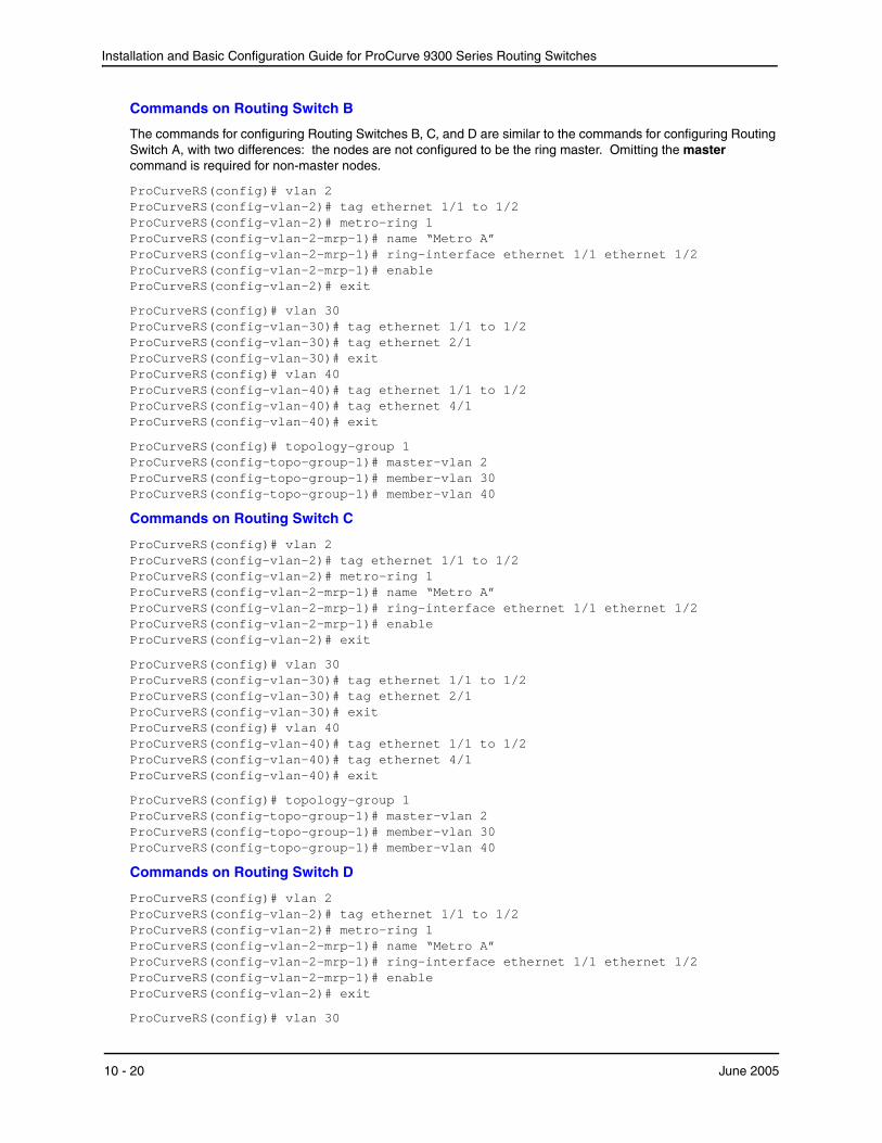
Installation and Basic Configuration Guide for ProCurve 9300 Series Routing Switches
Commands on Routing Switch B
The commands for configuring Routing Switches B, C, and D are similar to the commands for configuring Routing Switch A, with two differences: the nodes are not configured to be the ring master. Omitting the master command is required for non-master nodes.
ProCurveRS(config)# vlan 2 ProCurveRS(config-vlan-2)# tag ethernet 1/1 to 1/2 ProCurveRS(config-vlan-2)# metro-ring 1 ProCurveRS(config-vlan-2-mrp-1)# name “Metro A” ProCurveRS(config-vlan-2-mrp-1)# ring-interface ethernet 1/1 ethernet 1/2 ProCurveRS(config-vlan-2-mrp-1)# enable ProCurveRS(config-vlan-2)# exit
ProCurveRS(config)# vlan 30 ProCurveRS(config-vlan-30)# tag ethernet 1/1 to 1/2 ProCurveRS(config-vlan-30)# tag ethernet 2/1 ProCurveRS(config-vlan-30)# exit ProCurveRS(config)# vlan 40 ProCurveRS(config-vlan-40)# tag ethernet 1/1 to 1/2 ProCurveRS(config-vlan-40)# tag ethernet 4/1 ProCurveRS(config-vlan-40)# exit
ProCurveRS(config)# topology-group 1 ProCurveRS(config-topo-group-1)# master-vlan 2 ProCurveRS(config-topo-group-1)# member-vlan 30 ProCurveRS(config-topo-group-1)# member-vlan 40
Commands on Routing Switch C
ProCurveRS(config)# vlan 2 ProCurveRS(config-vlan-2)# tag ethernet 1/1 to 1/2 ProCurveRS(config-vlan-2)# metro-ring 1 ProCurveRS(config-vlan-2-mrp-1)# name “Metro A” ProCurveRS(config-vlan-2-mrp-1)# ring-interface ethernet 1/1 ethernet 1/2 ProCurveRS(config-vlan-2-mrp-1)# enable ProCurveRS(config-vlan-2)# exit
ProCurveRS(config)# vlan 30 ProCurveRS(config-vlan-30)# tag ethernet 1/1 to 1/2 ProCurveRS(config-vlan-30)# tag ethernet 2/1 ProCurveRS(config-vlan-30)# exit ProCurveRS(config)# vlan 40 ProCurveRS(config-vlan-40)# tag ethernet 1/1 to 1/2 ProCurveRS(config-vlan-40)# tag ethernet 4/1 ProCurveRS(config-vlan-40)# exit
ProCurveRS(config)# topology-group 1 ProCurveRS(config-topo-group-1)# master-vlan 2 ProCurveRS(config-topo-group-1)# member-vlan 30 ProCurveRS(config-topo-group-1)# member-vlan 40
Commands on Routing Switch D
ProCurveRS(config)# vlan 2 ProCurveRS(config-vlan-2)# tag ethernet 1/1 to 1/2 ProCurveRS(config-vlan-2)# metro-ring 1 ProCurveRS(config-vlan-2-mrp-1)# name “Metro A” ProCurveRS(config-vlan-2-mrp-1)# ring-interface ethernet 1/1 ethernet 1/2 ProCurveRS(config-vlan-2-mrp-1)# enable ProCurveRS(config-vlan-2)# exit
ProCurveRS(config)# vlan 30
10 - 20 June 2005
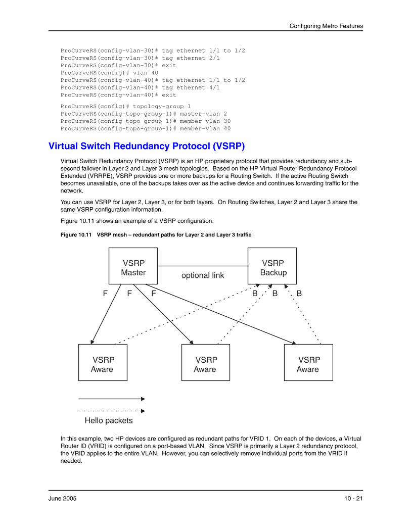
Configuring Metro Features
ProCurveRS(config-vlan-30)# tag ethernet 1/1 to 1/2 ProCurveRS(config-vlan-30)# tag ethernet 2/1 ProCurveRS(config-vlan-30)# exit ProCurveRS(config)# vlan 40 ProCurveRS(config-vlan-40)# tag ethernet 1/1 to 1/2 ProCurveRS(config-vlan-40)# tag ethernet 4/1 ProCurveRS(config-vlan-40)# exit
ProCurveRS(config)# topology-group 1 ProCurveRS(config-topo-group-1)# master-vlan 2 ProCurveRS(config-topo-group-1)# member-vlan 30 ProCurveRS(config-topo-group-1)# member-vlan 40
Virtual Switch Redundancy Protocol (VSRP)Virtual Switch Redundancy Protocol (VSRP) is an HP proprietary protocol that provides redundancy and sub-second failover in Layer 2 and Layer 3 mesh topologies. Based on the HP Virtual Router Redundancy Protocol Extended (VRRPE), VSRP provides one or more backups for a Routing Switch. If the active Routing Switch becomes unavailable, one of the backups takes over as the active device and continues forwarding traffic for the network.
You can use VSRP for Layer 2, Layer 3, or for both layers. On Routing Switches, Layer 2 and Layer 3 share the same VSRP configuration information.
Figure 10.11 shows an example of a VSRP configuration.
Figure 10.11 VSRP mesh – redundant paths for Layer 2 and Layer 3 traffic
B
VSRPAware
VSRPMaster optional link
VSRPAware
Hello packets
VSRPBackup
B BFF F
VSRPAware
In this example, two HP devices are configured as redundant paths for VRID 1. On each of the devices, a Virtual Router ID (VRID) is configured on a port-based VLAN. Since VSRP is primarily a Layer 2 redundancy protocol, the VRID applies to the entire VLAN. However, you can selectively remove individual ports from the VRID if needed.
June 2005 10 - 21
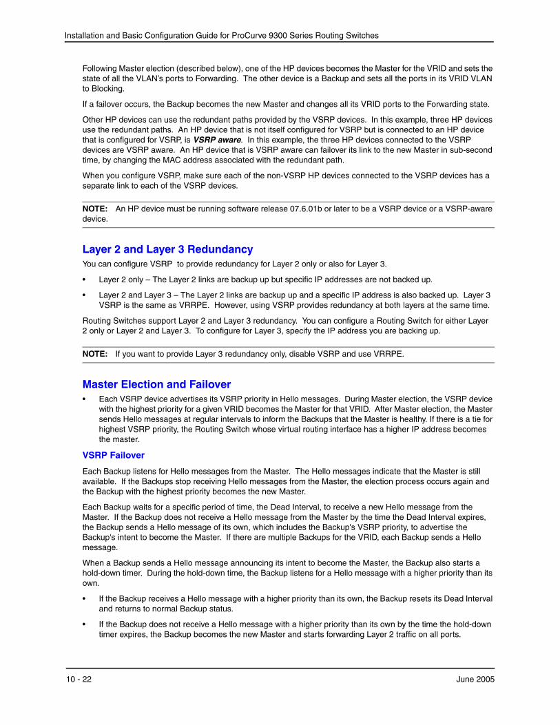
Installation and Basic Configuration Guide for ProCurve 9300 Series Routing Switches
Following Master election (described below), one of the HP devices becomes the Master for the VRID and sets the state of all the VLAN’s ports to Forwarding. The other device is a Backup and sets all the ports in its VRID VLAN to Blocking.
If a failover occurs, the Backup becomes the new Master and changes all its VRID ports to the Forwarding state.
Other HP devices can use the redundant paths provided by the VSRP devices. In this example, three HP devices use the redundant paths. An HP device that is not itself configured for VSRP but is connected to an HP device that is configured for VSRP, is VSRP aware. In this example, the three HP devices connected to the VSRP devices are VSRP aware. An HP device that is VSRP aware can failover its link to the new Master in sub-second time, by changing the MAC address associated with the redundant path.
When you configure VSRP, make sure each of the non-VSRP HP devices connected to the VSRP devices has a separate link to each of the VSRP devices.
NOTE: An HP device must be running software release 07.6.01b or later to be a VSRP device or a VSRP-aware device.
Layer 2 and Layer 3 RedundancyYou can configure VSRP to provide redundancy for Layer 2 only or also for Layer 3.
• Layer 2 only – The Layer 2 links are backup up but specific IP addresses are not backed up.
• Layer 2 and Layer 3 – The Layer 2 links are backup up and a specific IP address is also backed up. Layer 3 VSRP is the same as VRRPE. However, using VSRP provides redundancy at both layers at the same time.
Routing Switches support Layer 2 and Layer 3 redundancy. You can configure a Routing Switch for either Layer 2 only or Layer 2 and Layer 3. To configure for Layer 3, specify the IP address you are backing up.
NOTE: If you want to provide Layer 3 redundancy only, disable VSRP and use VRRPE.
Master Election and Failover• Each VSRP device advertises its VSRP priority in Hello messages. During Master election, the VSRP device
with the highest priority for a given VRID becomes the Master for that VRID. After Master election, the Master sends Hello messages at regular intervals to inform the Backups that the Master is healthy. If there is a tie for highest VSRP priority, the Routing Switch whose virtual routing interface has a higher IP address becomes the master.
VSRP Failover
Each Backup listens for Hello messages from the Master. The Hello messages indicate that the Master is still available. If the Backups stop receiving Hello messages from the Master, the election process occurs again and the Backup with the highest priority becomes the new Master.
Each Backup waits for a specific period of time, the Dead Interval, to receive a new Hello message from the Master. If the Backup does not receive a Hello message from the Master by the time the Dead Interval expires, the Backup sends a Hello message of its own, which includes the Backup's VSRP priority, to advertise the Backup's intent to become the Master. If there are multiple Backups for the VRID, each Backup sends a Hello message.
When a Backup sends a Hello message announcing its intent to become the Master, the Backup also starts a hold-down timer. During the hold-down time, the Backup listens for a Hello message with a higher priority than its own.
• If the Backup receives a Hello message with a higher priority than its own, the Backup resets its Dead Interval and returns to normal Backup status.
• If the Backup does not receive a Hello message with a higher priority than its own by the time the hold-down timer expires, the Backup becomes the new Master and starts forwarding Layer 2 traffic on all ports.
10 - 22 June 2005
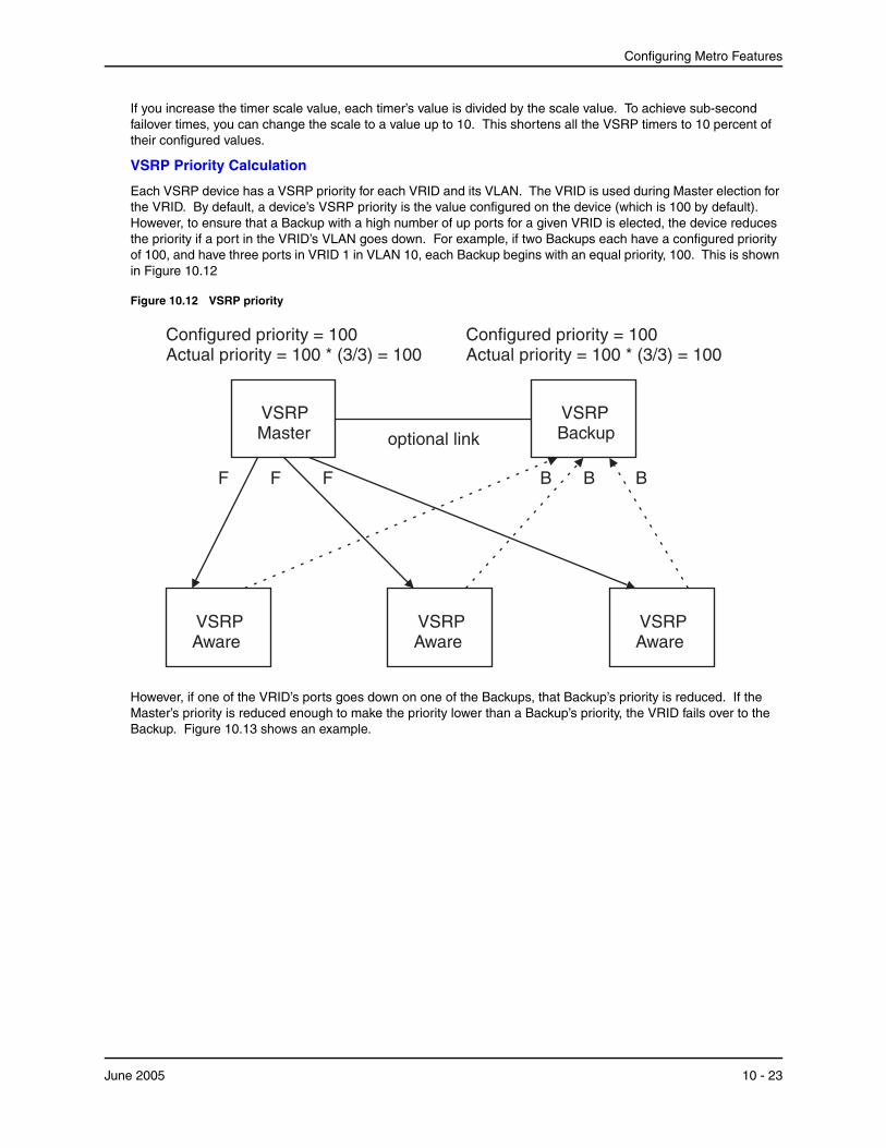
Configuring Metro Features
If you increase the timer scale value, each timer’s value is divided by the scale value. To achieve sub-second failover times, you can change the scale to a value up to 10. This shortens all the VSRP timers to 10 percent of their configured values.
VSRP Priority Calculation
Each VSRP device has a VSRP priority for each VRID and its VLAN. The VRID is used during Master election for the VRID. By default, a device’s VSRP priority is the value configured on the device (which is 100 by default). However, to ensure that a Backup with a high number of up ports for a given VRID is elected, the device reduces the priority if a port in the VRID’s VLAN goes down. For example, if two Backups each have a configured priority of 100, and have three ports in VRID 1 in VLAN 10, each Backup begins with an equal priority, 100. This is shown in Figure 10.12
Figure 10.12 VSRP priority
B
VSRPAware
VSRPMaster optional link
VSRPAware
Configured priority = 100Actual priority = 100 * (3/3) = 100
VSRPBackup
B BFF
VSRPAware
F
Configured priority = 100Actual priority = 100 * (3/3) = 100
However, if one of the VRID’s ports goes down on one of the Backups, that Backup’s priority is reduced. If the Master’s priority is reduced enough to make the priority lower than a Backup’s priority, the VRID fails over to the Backup. Figure 10.13 shows an example.
June 2005 10 - 23
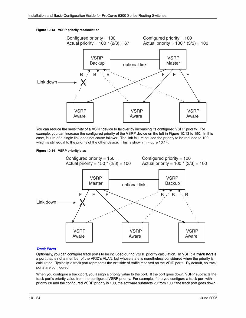
Installation and Basic Configuration Guide for ProCurve 9300 Series Routing Switches
Figure 10.13 VSRP priority recalculation
F
VSRPAware
VSRPBackup optional link
VSRPAware
VSRPMaster
F FBB B
VSRPAware
Configured priority = 100Actual priority = 100 * (3/3) = 100
Configured priority = 100Actual priority = 100 * (2/3) = 67
XLink down
You can reduce the sensitivity of a VSRP device to failover by increasing its configured VSRP priority. For example, you can increase the configured priority of the VSRP device on the left in Figure 10.13 to 150. In this case, failure of a single link does not cause failover. The link failure caused the priority to be reduced to 100, which is still equal to the priority of the other device. This is shown in Figure 10.14.
Figure 10.14 VSRP priority bias
Configured priority = 100Actual priority = 100 * (3/3) = 100
Configured priority = 150Actual priority = 150 * (2/3) = 100
B
VSRPAware
VSRPMaster optional link
VSRPAware
VSRPBackup
B BFF
VSRPAware
F
XLink down
Track PortsOptionally, you can configure track ports to be included during VSRP priority calculation. In VSRP, a track port is a port that is not a member of the VRID’s VLAN, but whose state is nonetheless considered when the priority is calculated. Typically, a track port represents the exit side of traffic received on the VRID ports. By default, no track ports are configured.
When you configure a track port, you assign a priority value to the port. If the port goes down, VSRP subtracts the track port’s priority value from the configured VSRP priority. For example, if the you configure a track port with priority 20 and the configured VSRP priority is 100, the software subtracts 20 from 100 if the track port goes down,
10 - 24 June 2005
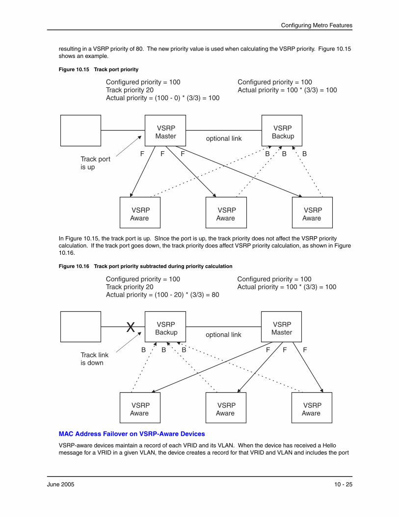
Configuring Metro Features
resulting in a VSRP priority of 80. The new priority value is used when calculating the VSRP priority. Figure 10.15 shows an example.
Figure 10.15 Track port priority
B
VSRPAware
VSRPMaster optional link
VSRPAware
Configured priority = 100Actual priority = 100 * (3/3) = 100
VSRPBackup
B BFTrack portis up
VSRPAware
F
Configured priority = 100Track priority 20Actual priority = (100 - 0) * (3/3) = 100
F
In Figure 10.15, the track port is up. SInce the port is up, the track priority does not affect the VSRP priority calculation. If the track port goes down, the track priority does affect VSRP priority calculation, as shown in Figure 10.16.
Figure 10.16 Track port priority subtracted during priority calculation
VSRPAware
VSRPBackup optional link
VSRPAware
Configured priority = 100Actual priority = 100 * (3/3) = 100
VSRPMaster
Track linkis down
VSRPAware
Configured priority = 100Track priority 20Actual priority = (100 - 20) * (3/3) = 80
X
FF FBB B
MAC Address Failover on VSRP-Aware Devices
VSRP-aware devices maintain a record of each VRID and its VLAN. When the device has received a Hello message for a VRID in a given VLAN, the device creates a record for that VRID and VLAN and includes the port
June 2005 10 - 25
Installation and Basic Configuration Guide for ProCurve 9300 Series Routing Switches
number in the record. Each subsequent time the device receives a Hello message for the same VRID and VLAN, the device checks the port number.
• If the port number is the same as the port that previously received a Hello message, the VSRP-aware device assumes that the message came from the same VSRP Master that sent the previous message.
• If the port number does not match, the VSRP-aware device assumes that a VSRP failover has occurred to a new Master, and moves the MAC addresses learned on the previous port to the new port.
The VRID records age out if unused. This can occur if the VSRP-aware device becomes disconnected from the Master. The VSRP-aware device will wait for a Hello message for the period of time equal to the following:
VRID Age = Dead Interval + Hold-down Interval + (3 x Hello Interval)
The values for these timers are determined by the VSRP device sending the Hello messages. If the Master uses the default timer values, the age time for VRID records on the VSRP-aware devices is as follows:
3 + 2 + (3 x 1) = 8 seconds
In this case, if the VSRP-aware device does not receive a new Hello message for a VRID in a given VLAN, on any port, the device assumes the connection to the Master is unavailable and removes the VRID record.
Timer Scale
The VSRP Hello interval, Dead interval, Backup Hello interval, and Hold-down interval timers are individually configurable. You also can easily change all the timers at the same time while preserving the ratios among their values. To do so, change the timer scale. The timer scale is a value used by the software to calculate the timers. The software divides a timer’s value by the timer scale value. By default, the scale is 1. This means the VSRP timer values are the same as the values in the configuration.
VSRP-Aware Security FeaturesSoftware release 07.6.04 and later enhances the security of VSRP-aware switches against unauthorized VSRP hello packets by enabling you to configure VSRP-aware security parameters.
Without VSRP-aware security configured, a VSRP-aware device passively learns the authentication method conveyed by the received VSRP hello packet. The VSRP-aware device then stores the authentication method until it ages out with the aware entry.
With VSRP-aware security, you can:
• Define the specific authentication parameters that a VSRP-aware device will use on a VSRP backup switch. The authentication parameters that you define will not age out.
• Define a list of ports that have authentic VSRP backup switch connections. For ports included in the list, the VSRP-aware switch will process VSRP hello packets using the VSRP-aware security configuration. Conversely, for ports not included in the list, the VSRP-aware switch will not use the VSRP-aware security configuration.
If VSRP hello packets do not meet the acceptance criteria, the VSRP-aware device forwards the packets normally, without any VSRP-aware security processing.
VSRP ParametersTable 10.4 lists the VSRP parameters.
Table 10.4: VSRP Parameters
Parameter Description Default See page...
Protocol VSRP state
Note: On a Routing Switch, you must disable VSRP to use VRRPE or VRRP.
Enabled 10-30
10 - 26 June 2005

Configuring Metro Features
Virtual Router ID (VRID)
The ID of the virtual switch you are creating by configuring multiple devices as redundant links. You must configure the same VRID on each device that you want to use to back up the links.
None 10-29
Timer scale The value used by the software to calculate all VSRP timers. Increasing the timer scale value decreases the length of all the VSRP timers equally, without changing the ratio of one timer to another.
1 10-30
Interface Parameters
Authentication type
The type of authentication the VSRP devices use to validate VSRP packets. On Routing Switches, the authentication type must match the authentication type the VRID’s port uses with other routing protocols such as OSPF.
• No authentication – The interfaces do not use authentication. This is the VRRP default.
• Simple – The interface uses a simple text-string as a password in packets sent on the interface. If the interface uses simple password authentication, the VRID configured on the interface must use the same authentication type and the same password.
Note: MD5 is not supported.
No authentication 10-31
VSRP-Aware Security Parameters
VSRP-Aware Authentication type
The type of authentication the VSRP-aware devices will use on a VSRP backup switch.
• No authentication – The device does not accept incoming packets that have authentication strings.
• Simple – The device uses a simple text-string as the authentication string for accepting incoming packets.
Not configured 10-32
VRID Parameters
VSRP device type
Whether the device is a VSRP Backup for the VRID.
All VSRP devices for a given VRID are Backups.
Not configured 10-29
VSRP ports The ports in the VRID’s VLAN that you want to use as VRID interfaces. You can selectively exclude individual ports from VSRP while allowing them to remain in the VLAN.
All ports in the VRID’s VLAN
10-32
Table 10.4: VSRP Parameters (Continued)
Parameter Description Default See page...
June 2005 10 - 27
Installation and Basic Configuration Guide for ProCurve 9300 Series Routing Switches
VRID IP address
A gateway address you are backing up. Configuring an IP address provides VRRPE Layer 3 redundancy in addition to VSRP LAyer 2 redundancy.
The VRID IP address must be in the same subnet as a real IP address configured on the VSRP interface, but cannot be the same as a real IP address configured on the interface.
None 10-33
Backup priority A numeric value that determines a Backup’s preferability for becoming the Master for the VRID. During negotiation, the device with the highest priority becomes the Master.
In VSRP, all devices are Backups and have the same priority by default.
If two or more Backups are tied with the highest priority, the Backup with the highest IP address becomes the Master for the VRID.
100 for all Backups 10-33
Preference of timer source
When you save a Backup’s configuration, the software can save the configured VSRP timer values or the VSRP timer values received from the Master.
Saving the current timer values instead of the configured ones helps ensure consistent timer usage for all the VRID’s devices.
Note: The Backup always gets its timer scale value from the Master.
Configured timer values are saved
10-33
Time-to-Live (TTL)
The maximum number of hops a VSRP Hello packet can traverse before being dropped. You can specify from 1 – 255.
2 10-34
Hello interval The amount of time between Hello messages from the Master to the Backups for a given VRID.
The interval can be from 1 – 84 seconds.
One second 10-34
Dead interval The amount of time a Backup waits for a Hello message from the Master for the VRID before determining that the Master is no longer active.
If the Master does not send a Hello message before the dead interval expires, the Backups negotiate (compare priorities) to select a new Master for the VRID.
Three times the Hello Interval
10-34
Table 10.4: VSRP Parameters (Continued)
Parameter Description Default See page...
10 - 28 June 2005
Configuring Metro Features
Configuring Basic VSRP Parameters Using the CLITo configure VSRP, perform the following required tasks:
Backup Hello state and interval
The amount of time between Hello messages from a Backup to the Master.
The message interval can be from 60 – 3600 seconds.
You must enable the Backup to send the messages. The messages are disabled by default on Backups. The current Master sends Hello messages by default.
Disabled
60 seconds when enabled
10-35
Hold-down interval
The amount of time a Backup that has sent a Hello packet announcing its intent to become Master waits before beginning to forward traffic for the VRID. The hold-down interval prevents Layer 2 loops from occurring during VSRP’s rapid failover.
The interval can from 1 – 84 seconds.
2 seconds 10-35
Track priority A VSRP priority value assigned to the tracked port(s). If a tracked port’s link goes down, the VRID port’s VSRP priority is reduced by the amount of the tracked port’s priority.
5 10-35
Track port A track port is a port or virtual routing interface that is outside the VRID but whose link state is tracked by the VRID. Typically, the tracked interface represents the other side of VRID traffic flow through the device.
If the link for a tracked interface goes down, the VSRP priority of the VRID interface is changed, causing the devices to renegotiate for Master.
None 10-36
Backup preempt mode
Prevents a Backup with a higher VSRP priority from taking control of the VRID from another Backup that has a lower priority but has already assumed control of the VRID.
Enabled 10-36
VRID active state
The active state of the VSRP VRID. Disabled 10-29
RIP Parameters
Suppression of RIP advertisements
A Routing Switch that is running RIP normally advertises routes to a backed up VRID even when the Routing Switch is not currently the active Routing Switch for the VRID. Suppression of these advertisements helps ensure that other Routing Switches do not receive invalid route paths for the VRID.
Note: This parameter is valid only on Routing Switches.
Disabled
(routes are advertised)
10-36
Table 10.4: VSRP Parameters (Continued)
Parameter Description Default See page...
June 2005 10 - 29
Installation and Basic Configuration Guide for ProCurve 9300 Series Routing Switches
• Configure a port-based VLAN containing the ports for which you want to provide VSRP service.
NOTE: If you already have a port-based VLAN but only want to use VSRP on a sub-set of the VLANs ports, you can selectively remove ports from VSRP service in the VLAN. See “Removing a Port from the VRID’s VLAN” on page 10-32.
• Configure a VRID.
• Specify that the device is a backup. Since VSRP, like VRRPE, does not have an “owner”, all VSRP devices are backups. The active device for a VRID is elected based on the VRID priority, which is configurable.
• Activate the VRID.
The following example shows a simple VSRP configuration.
ProCurveRS(config)# vlan 200 ProCurveRS(config-vlan-200)# tag ethernet 1/1 to 1/8 ProCurveRS(config-vlan-200)# vsrp vrid 1 ProCurveRS(config-vlan-200-vrid-1)# backup ProCurveRS(config-vlan-200-vrid-1)# activate
Syntax: [no] vsrp vrid <num>
The <num> parameter specifies the VRID and can be from 1 – 255.
Syntax: [no] backup [priority <value>] [track-priority <value>]
This command is required. In VSRP, all devices on which a VRID are configured are Backups. The Master is then elected based on the VSRP priority of each device. There is no “owner” device as there is in VRRP.
For information about the command’s optional parameters, see the following:
• “Changing the Backup Priority” on page 10-33
• “Changing the Default Track Priority” on page 10-35
Syntax: [no] activate
or
Syntax: enable | disable
Configuring Optional VSRP Parameters Using the CLIThe following sections describe how to configure optional VSRP parameters.
Disabling or Re-Enabling VSRP
VSRP is enabled by default. On a Routing Switch, if you want to use VRRP or VRRPE for Layer 3 redundancy instead of VSRP, you need to disable VSRP first. To do so, enter the following command at the global CONFIG level:
ProCurveRS(config)# no router vsrp router vsrp is disabled. All vsrp config data will be lost when writing to flash
To re-enable the protocol, enter the following command:
ProCurveRS(config)# router vsrp
Syntax: [no] router vsrp
Changing the Timer Scale
To achieve sub-second failover times, you can shorten the duration of all VSRP timers by adjusting the timer scale. The timer scale is a value used by the software to calculate the timers. By default, the scale value is 1. If you increase the timer scale, each timer’s value is divided by the scale value. Using the timer scale to adjust VSRP
10 - 30 June 2005
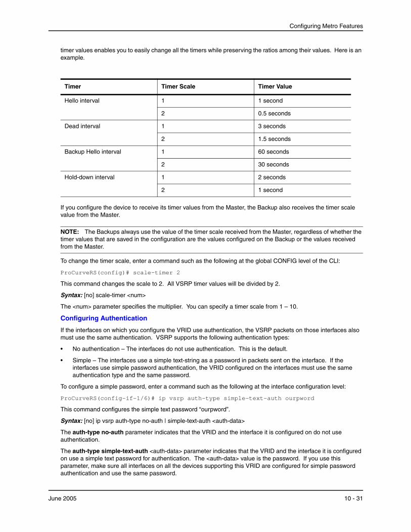
Configuring Metro Features
timer values enables you to easily change all the timers while preserving the ratios among their values. Here is an example.
Timer Timer Scale Timer Value
Hello interval 1 1 second
2 0.5 seconds
Dead interval 1 3 seconds
2 1.5 seconds
Backup Hello interval 1 60 seconds
2 30 seconds
Hold-down interval 1 2 seconds
2 1 second
If you configure the device to receive its timer values from the Master, the Backup also receives the timer scale value from the Master.
NOTE: The Backups always use the value of the timer scale received from the Master, regardless of whether the timer values that are saved in the configuration are the values configured on the Backup or the values received from the Master.
To change the timer scale, enter a command such as the following at the global CONFIG level of the CLI:
ProCurveRS(config)# scale-timer 2
This command changes the scale to 2. All VSRP timer values will be divided by 2.
Syntax: [no] scale-timer <num>
The <num> parameter specifies the multiplier. You can specify a timer scale from 1 – 10.
Configuring Authentication
If the interfaces on which you configure the VRID use authentication, the VSRP packets on those interfaces also must use the same authentication. VSRP supports the following authentication types:
• No authentication – The interfaces do not use authentication. This is the default.
• Simple – The interfaces use a simple text-string as a password in packets sent on the interface. If the interfaces use simple password authentication, the VRID configured on the interfaces must use the same authentication type and the same password.
To configure a simple password, enter a command such as the following at the interface configuration level:
ProCurveRS(config-if-1/6)# ip vsrp auth-type simple-text-auth ourpword
This command configures the simple text password “ourpword”.
Syntax: [no] ip vsrp auth-type no-auth | simple-text-auth <auth-data>
The auth-type no-auth parameter indicates that the VRID and the interface it is configured on do not use authentication.
The auth-type simple-text-auth <auth-data> parameter indicates that the VRID and the interface it is configured on use a simple text password for authentication. The <auth-data> value is the password. If you use this parameter, make sure all interfaces on all the devices supporting this VRID are configured for simple password authentication and use the same password.
June 2005 10 - 31
Installation and Basic Configuration Guide for ProCurve 9300 Series Routing Switches
Configuring Security Features on a VSRP-Aware Device
NOTE: This feature is available in software releases 07.6.04 and later.
The VSRP-aware security feature enables you to:
• Define the specific authentication parameters that a VSRP-aware device will use on a VSRP backup switch. The authentication parameters that you define will not age out.
• Define a list of ports that have authentic VSRP backup switch connections. For ports included in the list, the VSRP-aware switch will process VSRP hello packets using the VSRP-aware security configuration. Conversely, for ports not included in the list, the VSRP-aware switch will not use the VSRP-aware security configuration.
If VSRP hello packets do not meet the acceptance criteria, the VSRP-aware device forwards the packets normally, without any VSRP-aware security processing.
Specifying an Authentication String for VSRP Hello PacketsThe following configuration defines pri-key as the authentication string for accepting incoming VSRP hello packets. In this example, the VSRP-aware device will accept all incoming packets that have this authorization string.
ProCurveRS(config)# vlan 10 ProCurveRS(config-vlan-10)# vsrp-aware vrid 3 simple-text-auth pri-key
Syntax: vsrp-aware vrid <vrid number> simple text auth <string>
Specifying no Authentication for VSRP Hello PacketsThe following configuration specifies no authentication as the preferred VSRP-aware security method. In this case, the VSRP device will not accept incoming packets that have authentication strings.
ProCurveRS(config)# vlan 10 ProCurveRS(config-vlan-10)# vsrp-aware vrid 2 no-auth
Syntax: vsrp-aware vrid <vrid number> no-auth
The following configuration specifies no authentication for VSRP hello packets received on ports 1/1, 1/2, 1/3, and 1/4 in VRID 4. For these ports, the VSRP device will not accept incoming packets that have authentication strings.
ProCurveRS(config)# vlan 10 ProCurveRS(config-vlan-10)# vsrp-aware vrid 4 no-auth port-list ethe 1/1 to 1/4
Syntax: vsrp-aware vrid <vrid number> no-auth port-list <port range>
<vrid number> is a valid VRID (from 1 to 255).
no-auth specifies no authentication as the preferred VSRP-aware security method. The VSRP device will not accept incoming packets that have authentication strings.
simple-text-auth <string> specifies the authentication string for accepting VSRP hello packets, where <string> can be up to 8 characters.
port-list <port range> specifies the range of ports to include in the configuration.
Removing a Port from the VRID’s VLAN
By default, all the ports in the VLAN on which you configure a VRID are interfaces for the VRID. You can remove a port from the VRID while allowing it to remain in the VLAN.
Removing a port is useful in the following cases:
• There is no risk of a loop occurring, such as when the port is attached directly to an end host.
• You plan to use a port in an MRP ring.
To remove a port from a VRID, enter a command such as the following at the configuration level for the VRID:
ProCurveRS(config-vlan-200-vrid-1)# no include-port ethernet 1/2
10 - 32 June 2005
Configuring Metro Features
Syntax: [no] include-port ethernet <portnum>
The ethernet <portnum> parameter specifies the port you are removing from the VRID. The port remains in the VLAN but its forwarding state is not controlled by VSRP.
Configuring a VRID IP Address
If you are configuring a Routing Switch for VSRP, you can specify an IP address to back up. When you specify an IP address, VSRP provides redundancy for the address. This is useful if you want to back up the gateway address used by hosts attached to the VSRP Backups.
VSRP does not require you to specify an IP address. If you do not specify an address, VSRP provides Layer 2 redundancy. If you do specify an address, VSRP provides Layer 2 and Layer 3 redundancy.
The Layer 3 redundancy support is the same as VRRPE support. For information, see the “Configuring VRRP and VRRPE“ chapter in the Advanced Configuration and Management Guide for ProCurve 9300/9400 Series Routing Switches.
NOTE: The VRID IP address must be in the same subnet as a real IP address configured on the VSRP interface, but cannot be the same as a real IP address configured on the interface.
NOTE: Failover applies to both Layer 2 and Layer 3.
To specify an IP address to back up, enter a command such as the following at the configuration level for the VRID:
ProCurveRS(config-vlan-200-vrid-1)# ip-address 10.10.10.1
Syntax: [no] ip-address <ip-addr>
or
Syntax: [no] ip address <ip-addr>
Changing the Backup Priority
When you enter the backup command to configure the device as a VSRP Backup for the VRID, you also can change the backup priority and the track priority.
• The backup priority is used for election of the Master. The VSRP Backup with the highest priority value for the VRID is elected as the Master for that VRID. The default priority is 100. If two or more Backups are tied with the highest priority, the Backup with the highest IP address becomes the Master for the VRID.
• The track priority is used with the track port feature. See “VSRP Priority Calculation” on page 10-23 and “Changing the Default Track Priority” on page 10-35.
To change the backup priority, enter a command such as the following at the configuration level for the VRID:
ProCurveRS(config-vlan-200-vrid-1)# backup priority 75
Syntax: [no] backup [priority <value>] [track-priority <value>]
The priority <value> parameter specifies the VRRP priority for this interface and VRID. You can specify a value from 3 – 254. The default is 100.
For a description of the track-priority <value> parameter, see “Changing the Default Track Priority” on page 10-35.
Saving the Timer Values Received from the Master
The Hello messages sent by a VRID’s master contain the VRID values for the following VSRP timers:
• Hello interval
• Dead interval
• Backup Hello interval
June 2005 10 - 33
Installation and Basic Configuration Guide for ProCurve 9300 Series Routing Switches
• Hold-down interval
By default, each Backup saves the configured timer values to its startup-config file when you save the device’s configuration.
You can configure a Backup to instead save the current timer values received from the Master when you save the configuration. Saving the current timer values instead of the configured ones helps ensure consistent timer usage for all the VRID’s devices.
NOTE: The Backups always use the value of the timer scale received from the Master, regardless of whether the timer values that are saved in the configuration are the values configured on the Backup or the values received from the Master.
To configure a Backup to save the VSRP timer values received from the Master instead of the timer values configured on the Backup, enter the following command:
ProCurveRS(config-vlan-200-vrid-1)# save-current-values
Syntax: [no] save-current-values
Changing the Time-To-Live (TTL)
A VSRP Hello packet’s TTL specifies how many hops the packet can traverse before being dropped. You can specify from 1 – 255. The default TTL is 2. When a VSRP device (Master or Backup) sends a VSRP HEllo packet, the device subtracts one from the TTL. Thus, if the TTL is 2, the device that originates the Hello packet sends it out with a TTL of 1. Each subsequent device that receives the packet also subtracts one from the packet’s TTL. When the packet has a TTL of 1, the receiving device subtracts 1 and then drops the packet because the TTL is zero.
NOTE: An MRP ring is considered to be a single hop, regardless of the number of nodes in the ring.
To change the TTL for a VRID, enter a command such as the following at the configuration level for the VRID:
ProCurveRS(config-vlan-200-vrid-1)# initial-ttl 5
Syntax: [no] initial-ttl <num>
The <num> parameter specifies the TTL and can be from 1 – 255. The default TTL is 2.
Changing the Hello Interval
The Master periodically sends Hello messages to the Backups. To change the Hello interval, enter a command such as the following at the configuration level for the VRID:
ProCurveRS(config-vlan-200-vrid-1)# hello-interval 10
Syntax: [no] hello-interval <num>
The <num> parameter specifies the interval and can be from 1 – 84 seconds. The default is 1 second.
NOTE: The default Dead interval is three times the Hello interval plus one-half second. Generally, if you change the Hello interval, you also should change the Dead interval on the Backups.
NOTE: If you change the timer scale, the change affects the actual number of seconds.
Changing the Dead Interval
The Dead interval is the number of seconds a Backup waits for a Hello message from the Master before determining that the Master is dead. The default is 3 seconds. This is three times the default Hello interval.
To change the Dead interval, enter a command such as the following at the configuration level for the VRID:
ProCurveRS(config-vlan-200-vrid-1)# dead-interval 30
Syntax: [no] dead-interval <num>
10 - 34 June 2005

Configuring Metro Features
The <num> parameter specifies the interval and can be from 1 – 84 seconds. The default is 3 seconds.
NOTE: If you change the timer scale, the change affects the actual number of seconds.
Changing the Backup Hello State and Interval
By default, Backups do not send Hello messages to advertise themselves to the Master. You can enable these messages if desired and also change the message interval.
To enable a Backup to send Hello messages to the Master, enter a command such as the following at the configuration level for the VRID:
ProCurveRS(config-vlan-200-vrid-1)# advertise backup
Syntax: [no] advertise backup
When a Backup is enabled to send Hello messages, the Backup sends a Hello message to the Master every 60 seconds by default. You can change the interval to be up to 3600 seconds.
To change the Backup Hello interval, enter a command such as the following at the configuration level for the VRID:
ProCurveRS(config-vlan-200-vrid-1)# backup-hello-interval 180
Syntax: [no] backup-hello-interval <num>
The <num> parameter specifies the message interval and can be from 60 – 3600 seconds. The default is 60 seconds.
NOTE: If you change the timer scale, the change affects the actual number of seconds.
Changing the Hold-Down Interval
The hold-down interval prevents Layer 2 loops from occurring during failover, by delaying the new Master from forwarding traffic long enough to ensure that the failed Master is really unavailable.
To change the Hold-down interval, enter a command such as the following at the configuration level for the VRID:
ProCurveRS(config-vlan-200-vrid-1)# hold-down-interval 4
Syntax: [no] hold-down-interval <num>
The <num> parameter specifies the hold-down interval and can be from 1 – 84 seconds. The default is 2 seconds.
NOTE: If you change the timer scale, the change affects the actual number of seconds.
Changing the Default Track Priority
When you configure a VRID to track the link state of other interfaces, if one of the tracked interface goes down, the software changes the VSRP priority of the VRID interface.
The software reduces the VRID priority by the amount of the priority of the tracked interface that went down. For example, if the VSRP interface’s priority is 100 and a tracked interface with track priority 60 goes down, the software changes the VSRP interface’s priority to 40. If another tracked interface goes down, the software reduces the VRID’s priority again, by the amount of the tracked interface’s track priority.
The default track priority for all track ports is 1. You can change the default track priority or override the default for an individual track port.
• To change the default track priority, use the backup track-priority command, described below.
• To override the default track priority for a specific track port, use the track-port command. See “Specifying a Track Port” on page 10-36.
To change the track priority, enter a command such as the following at the configuration level for the VRID:
ProCurveRS(config-vlan-200-vrid-1)# backup track-priority 2
June 2005 10 - 35
Installation and Basic Configuration Guide for ProCurve 9300 Series Routing Switches
Syntax: [no] backup [priority <value>] [track-priority <value>]
Specifying a Track Port
You can configure the VRID on one interface to track the link state of another interface on the device. This capability is useful for tracking the state of the exit interface for the path for which the VRID is providing redundancy. See “VSRP Priority Calculation” on page 10-23.
To configure a VRID to track an interface, enter a command such as the following at the configuration level for the VRID:
ProCurveRS(config-vlan-200-vrid-1)# track-port e 2/4
Syntax: [no] track-port ethernet <portnum> | ve <num> [priority <num>]
The priority <num> parameter changes the VSRP priority of the interface. If this interface goes down, the VRID’s VSRP priority is reduced by the amount of the track port priority you specify here.
NOTE: The priority <num> option changes the priority of the specified interface, overriding the default track port priority. To change the default track port priority, use the backup track-priority <num> command.
Disabling or Re-Enabling Backup Pre-Emption
By default, a Backup that has a higher priority than another Backup that has become the Master can preempt the Master, and take over the role of Master. If you want to prevent this behavior, disable preemption.
Preemption applies only to Backups and takes effect only when the Master has failed and a Backup has assumed ownership of the VRID. The feature prevents a Backup with a higher priority from taking over as Master from another Backup that has a lower priority but has already become the Master of the VRID.
Preemption is especially useful for preventing flapping in situations where there are multiple Backups and a Backup with a lower priority than another Backup has assumed ownership, because the Backup with the higher priority was unavailable when ownership changed.
If you enable the non-preempt mode (thus disabling the preemption feature) on all the Backups, the Backup that becomes the Master following the disappearance of the Master continues to be the Master. The new Master is not preempted.
To disable preemption on a Backup, enter a command such as the following at the configuration level for the VRID:
ProCurveRS(config-vlan-200-vrid-1)# non-preempt-mode
Syntax: [no] non-preempt-mode
Suppressing RIP Advertisement from Backups
Normally, for Layer 3 a VSRP Backup includes route information for a backed up IP address in RIP advertisements. As a result, other Routing Switches receive multiple paths for the backed up interface and might sometimes unsuccessfully use the path to the Backup rather than the path to the Master.
You can prevent the Backups from advertising route information for the backed up interface by enabling suppression of the advertisements.
NOTE: This parameter applies only if you specified an IP address to back up and is valid only on Routing Switches.
To suppress RIP advertisements, enter the following commands:
Router2(config)# router rip Router2(config-rip-router)# use-vrrp-path
Syntax: [no] use-vrrp-path
10 - 36 June 2005
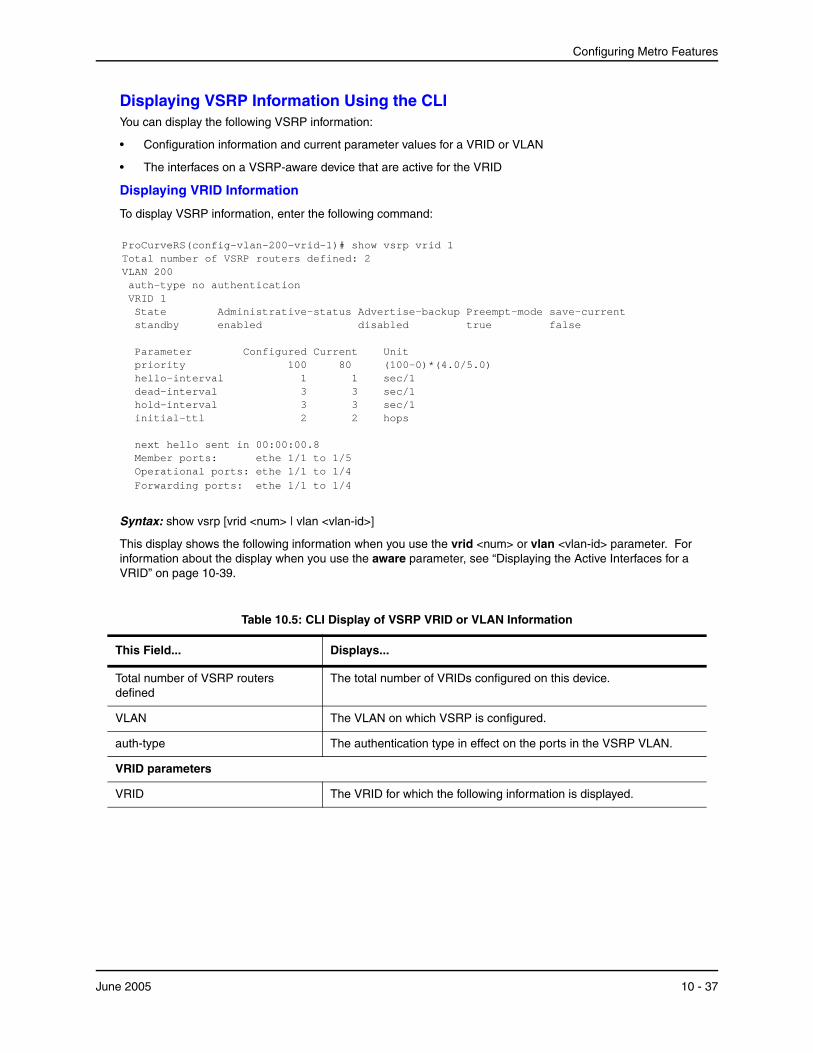
Configuring Metro Features
Displaying VSRP Information Using the CLIYou can display the following VSRP information:
• Configuration information and current parameter values for a VRID or VLAN
• The interfaces on a VSRP-aware device that are active for the VRID
Displaying VRID Information
To display VSRP information, enter the following command:
ProCurveRS(config-vlan-200-vrid-1)# show vsrp vrid 1 Total number of VSRP routers defined: 2 VLAN 200 auth-type no authentication VRID 1 State Administrative-status Advertise-backup Preempt-mode save-current standby enabled disabled true false Parameter Configured Current Unit priority 100 80 (100-0)*(4.0/5.0) hello-interval 1 1 sec/1 dead-interval 3 3 sec/1 hold-interval 3 3 sec/1 initial-ttl 2 2 hops next hello sent in 00:00:00.8 Member ports: ethe 1/1 to 1/5 Operational ports: ethe 1/1 to 1/4 Forwarding ports: ethe 1/1 to 1/4
Syntax: show vsrp [vrid <num> | vlan <vlan-id>]
This display shows the following information when you use the vrid <num> or vlan <vlan-id> parameter. For information about the display when you use the aware parameter, see “Displaying the Active Interfaces for a VRID” on page 10-39.
Table 10.5: CLI Display of VSRP VRID or VLAN Information
This Field... Displays...
Total number of VSRP routers defined
The total number of VRIDs configured on this device.
VLAN The VLAN on which VSRP is configured.
auth-type The authentication type in effect on the ports in the VSRP VLAN.
VRID parameters
VRID The VRID for which the following information is displayed.
June 2005 10 - 37
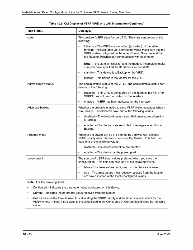
Installation and Basic Configuration Guide for ProCurve 9300 Series Routing Switches
state This device’s VSRP state for the VRID. The state can be one of the following:
• initialize – The VRID is not enabled (activated). If the state remains “initialize” after you activate the VRID, make sure that the VRID is also configured on the other Routing Switches and that the Routing Switches can communicate with each other. Note: If the state is “initialize” and the mode is incomplete, make sure you have specified the IP address for the VRID.
• standby – This device is a Backup for the VRID.
• master – This device is the Master for the VRID.
Administrative-status The administrative status of the VRID. The administrative status can be one of the following:
• disabled – The VRID is configured on the interface but VSRP or VRRPE has not been activated on the interface.
• enabled – VSRP has been activated on the interface.
Advertise-backup Whether the device is enabled to send VSRP Hello messages when it is a Backup. This field can have one of the following values:
• disabled – The device does not send Hello messages when it is a Backup.
• enabled – The device does send Hello messages when it is a Backup.
Preempt-mode Whether the device can be pre-empted by a device with a higher VSRP priority after this device becomes the Master. This field can have one of the following values:
• disabled – The device cannot be pre-empted.
• enabled – The device can be pre-empted.
save-current The source of VSRP timer values preferred when you save the configuration. This field can have one of the following values:
• false – The timer values configured on this device are saved.
• true – The timer values most recently received from the Master are saved instead of the locally configured values.
Note: For the following fields:
• Configured – indicates the parameter value configured on this device.
• Current – indicates the parameter value received from the Master.
• Unit – indicates the formula used tor calculating the VSRP priority and the timer scales in effect for the VSRP timers. A timer’s true value is the value listed in the Configured or Current field divided by the scale value.
Table 10.5: CLI Display of VSRP VRID or VLAN Information (Continued)
This Field... Displays...
10 - 38 June 2005
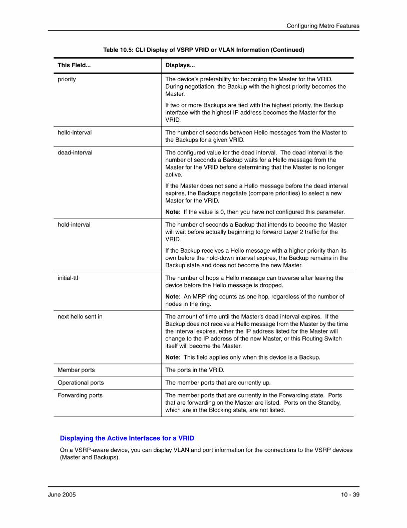
Configuring Metro Features
Displaying the Active Interfaces for a VRID
On a VSRP-aware device, you can display VLAN and port information for the connections to the VSRP devices (Master and Backups).
priority The device’s preferability for becoming the Master for the VRID. During negotiation, the Backup with the highest priority becomes the Master.
If two or more Backups are tied with the highest priority, the Backup interface with the highest IP address becomes the Master for the VRID.
hello-interval The number of seconds between Hello messages from the Master to the Backups for a given VRID.
dead-interval The configured value for the dead interval. The dead interval is the number of seconds a Backup waits for a Hello message from the Master for the VRID before determining that the Master is no longer active.
If the Master does not send a Hello message before the dead interval expires, the Backups negotiate (compare priorities) to select a new Master for the VRID.
Note: If the value is 0, then you have not configured this parameter.
hold-interval The number of seconds a Backup that intends to become the Master will wait before actually beginning to forward Layer 2 traffic for the VRID.
If the Backup receives a Hello message with a higher priority than its own before the hold-down interval expires, the Backup remains in the Backup state and does not become the new Master.
initial-ttl The number of hops a Hello message can traverse after leaving the device before the Hello message is dropped.
Note: An MRP ring counts as one hop, regardless of the number of nodes in the ring.
next hello sent in The amount of time until the Master’s dead interval expires. If the Backup does not receive a Hello message from the Master by the time the interval expires, either the IP address listed for the Master will change to the IP address of the new Master, or this Routing Switch itself will become the Master.
Note: This field applies only when this device is a Backup.
Member ports The ports in the VRID.
Operational ports The member ports that are currently up.
Forwarding ports The member ports that are currently in the Forwarding state. Ports that are forwarding on the Master are listed. Ports on the Standby, which are in the Blocking state, are not listed.
Table 10.5: CLI Display of VSRP VRID or VLAN Information (Continued)
This Field... Displays...
June 2005 10 - 39

Installation and Basic Configuration Guide for ProCurve 9300 Series Routing Switches
To display the active VRID interfaces, enter the following command on the VSRP-aware device:
ProCurveRS(config-vlan-200-vrid-1)# show vsrp aware Aware port listing VLAN ID VRID Last Port 100 1 3/2 200 2 4/1
Syntax: show vsrp aware
This display shows the following information when you use the aware parameter. For information about the display when you use the vrid <num> or vlan <vlan-id> parameter, see “Displaying VRID Information” on page 10-37.
Table 10.6: CLI Display of VSRP-Aware Information
This Field... Displays...
VLAN ID The VLAN that contains the VSRP-aware device’s connection with the VSRP Master and Backups.
VRID The VRID.
Last Port The most recent active port connection to the VRID. This is the port connected to the current Master. If a failover occurs, the VSRP-aware device changes the port to the port connected to the new Master. The VSRP-aware device uses this port to send and receive data through the backed up node.
Configuring VSRP Using the Web Management InterfaceYou can use the Web management interface to configure VSRP.
Enabling and Disabling VSRP
To enable VRRP, do the following:
1. Log on to the device using a valid user name and password for read-write access. The General System configuration panel is displayed.
2. Click Enable next to VSRP to enable it, or Disable to disable it.
3. Click the Apply button to apply your changes.
4. Select the Save link at the bottom of the dialog. Select Yes when prompted to save the configuration change to the startup-config file on the device’s flash memory.
Configuring VSRP Parameters
To configure VSRP parameters using the Web management interface, do the following:
1. Log on to the device using a valid user name and password for read-write access. The General System configuration panel is displayed.
2. Click on the plus sign next to Monitor in the tree view to expand the list of configuration options.
3. Click on the plus sign next to VSRP in the tree view to expand the list of configuration options.
4. Click on the Virtual Switch link.
• If virtual switches have been configured for the device, you see a list of virtual routers. Click the Modify button if you want to make changes to a virtual switch’s parameters, of click the Add virtual switch link to add a VSRP interface.
10 - 40 June 2005
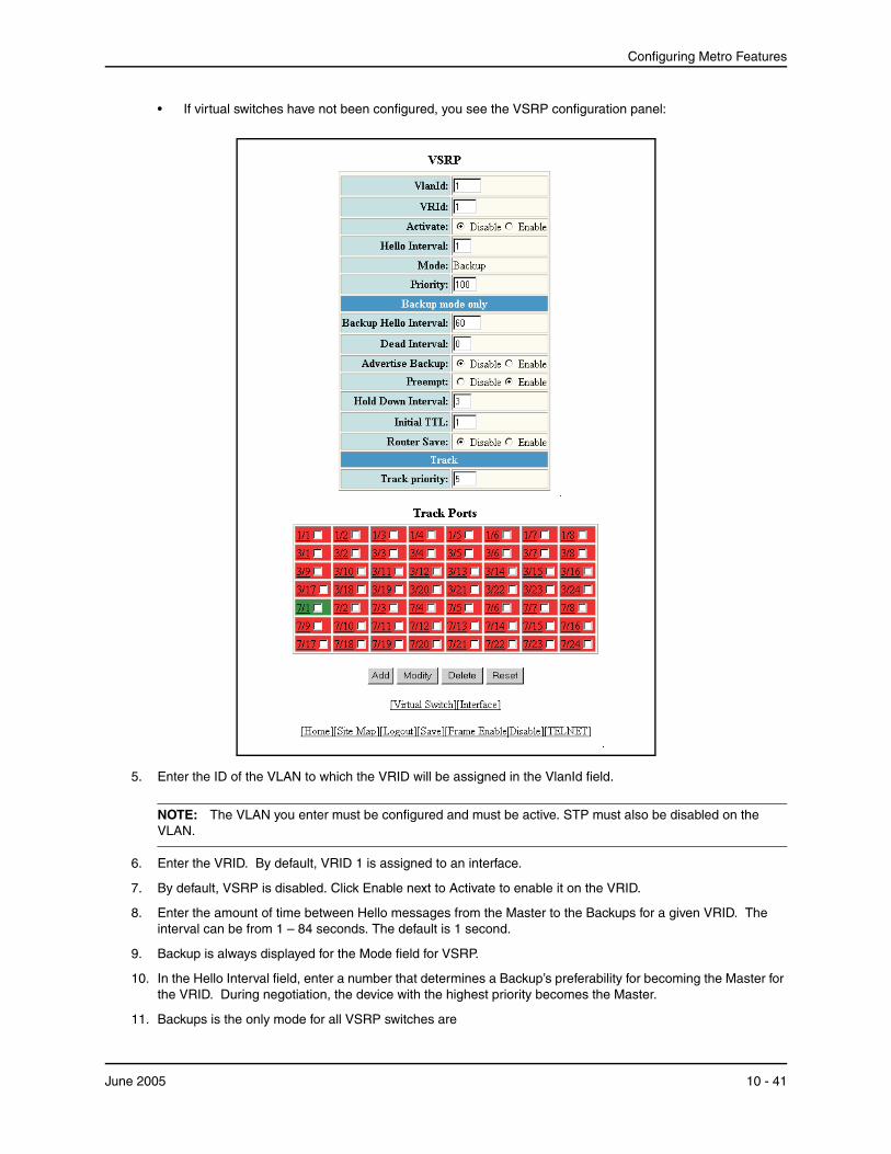
Configuring Metro Features
• If virtual switches have not been configured, you see the VSRP configuration panel:
5. Enter the ID of the VLAN to which the VRID will be assigned in the VlanId field.
NOTE: The VLAN you enter must be configured and must be active. STP must also be disabled on the VLAN.
6. Enter the VRID. By default, VRID 1 is assigned to an interface.
7. By default, VSRP is disabled. Click Enable next to Activate to enable it on the VRID.
8. Enter the amount of time between Hello messages from the Master to the Backups for a given VRID. The interval can be from 1 – 84 seconds. The default is 1 second.
9. Backup is always displayed for the Mode field for VSRP.
10. In the Hello Interval field, enter a number that determines a Backup’s preferability for becoming the Master for the VRID. During negotiation, the device with the highest priority becomes the Master.
11. Backups is the only mode for all VSRP switches are
June 2005 10 - 41

Installation and Basic Configuration Guide for ProCurve 9300 Series Routing Switches
12. Enter a value for Priority. If two or more Backups are tied with the highest priority, the Backup with the highest IP address becomes the Master for the VRID. The default Backup Priority is 100.
13. Enter a value for Backup Hello Interval. This interval is the number of seconds between Hello messages from the Master to the Backups for a given VRID. The interval can from 60 –3600 seconds, with 60 seconds as the default.
You must enable the Backup to send messages (advertise backup).
14. In the Dead Interval field. enter he amount of time a Backup waits for a Hello message from the Master for the VRID before determining that the Master is no longer active.
If the Master does not send a Hello message before the dead interval expires, the Backups negotiate (compare priorities) to select a new Master for the VRID.
15. Select Enable for Advertise Backup if you want to advertise routes to a backed up VRID even when the Routing Switch is not the current active Routing Switches for the VRID. Disabling the advertisements helps ensure that other Routing Switches do not receive invalid route paths for the VRID. The default is Disabled.
16. Select Enable for the Preempt field to prevent a Backup with a higher VSRP priority from taking control of the VRID from another Backup that has a lower priority but has already assumed control of the VRID. Select Disable if you do not want to disable this feature. The default is enabled.
17. Enter a value for the Hold Down Interval field. This is the amount of time a Backup that has sent a Hello packet announcing its intent to become Master waits before beginning to forward traffic for the VRID. The hold-down interval prevents Layer 2 loops from occurring during VSRP’s rapid failover. The interval can from 1 – 84 seconds. The default is 2 seconds.
18. Indicate the maximum time-to-live value, which is the number of hops a VSRP Hello packet can traverse before being dropped. You can specify from 1 – 255. The default is 2.
19. Click Enable for Router Save if you want the Backup to save the VSRP timer values received from the Master instead of the timer values configured on the Backup (above). VSRP timer values that will be saved are:
• Hello interval
• Dead interval
• Backup Hello interval
• Hold-down interval
20. Enter the Track Priority value or leave it blank to use the default. If a tracked port’s link goes down, the VRID port’s VSRP priority is reduced by the amount of the tracked port’s priority. The default priority is 5.
21. In the Track Ports section, place a check mark in the box for a port whose link state is tracked by the VRID. Typically, the tracked interface represents the other side of VRID traffic flow through the device.
If the link for a tracked interface goes down, the VSRP priority of the VRID interface is changed, causing the devices to renegotiate for Master.
22. Click the Add button to add the VSRP switch.
23. Select the Save link at the bottom of the dialog. Select Yes when prompted to save the configuration change to the startup-config file on the device’s flash memory.
Modifying Authentication Parameters
You can modify the password that was configured for a VSRP interface on a separate panel of the Web management interface.
1. Log on to the device using a valid user name and password for read-write access. The General System configuration panel is displayed.
2. Click on the plus sign next to Monitor in the tree view to expand the list of configuration options.
3. Click on the plus sign next to VSRP in the tree view to expand the list of configuration options.
10 - 42 June 2005

Configuring Metro Features
4. Click on the Interface link to display the VSRP Interface table, which lists all the VSRP interfaces on the device that have been configured.
5. Click the Modify button for the interface that you want to configure to display the VSRP Interface configuration panel.
6. Select the Authentication Type, either None, Simple Text Password or Ip Auth header.
7. Enter a password if the authentication is Simple Text Password. Leave this field blank if other password types are used.
8. Click the Apply button to the update the information for the VSRP.
9. Select the Save link at the bottom of the dialog. Select Yes when prompted to save the configuration change to the startup-config file on the device’s flash memory.
Displaying VSRP Statistics Using the Web Management InterfaceTo display VSRP statistics using the Web management interface:
1. Log on to the device using a valid user name and password for read-write access. The System configuration panel is displayed.
2. Click on the plus sign next to Monitor in the tree view to expand the list of configuration options.
3. Click on the plus sign next to VSRP in the tree view to expand the list of configuration options.
June 2005 10 - 43
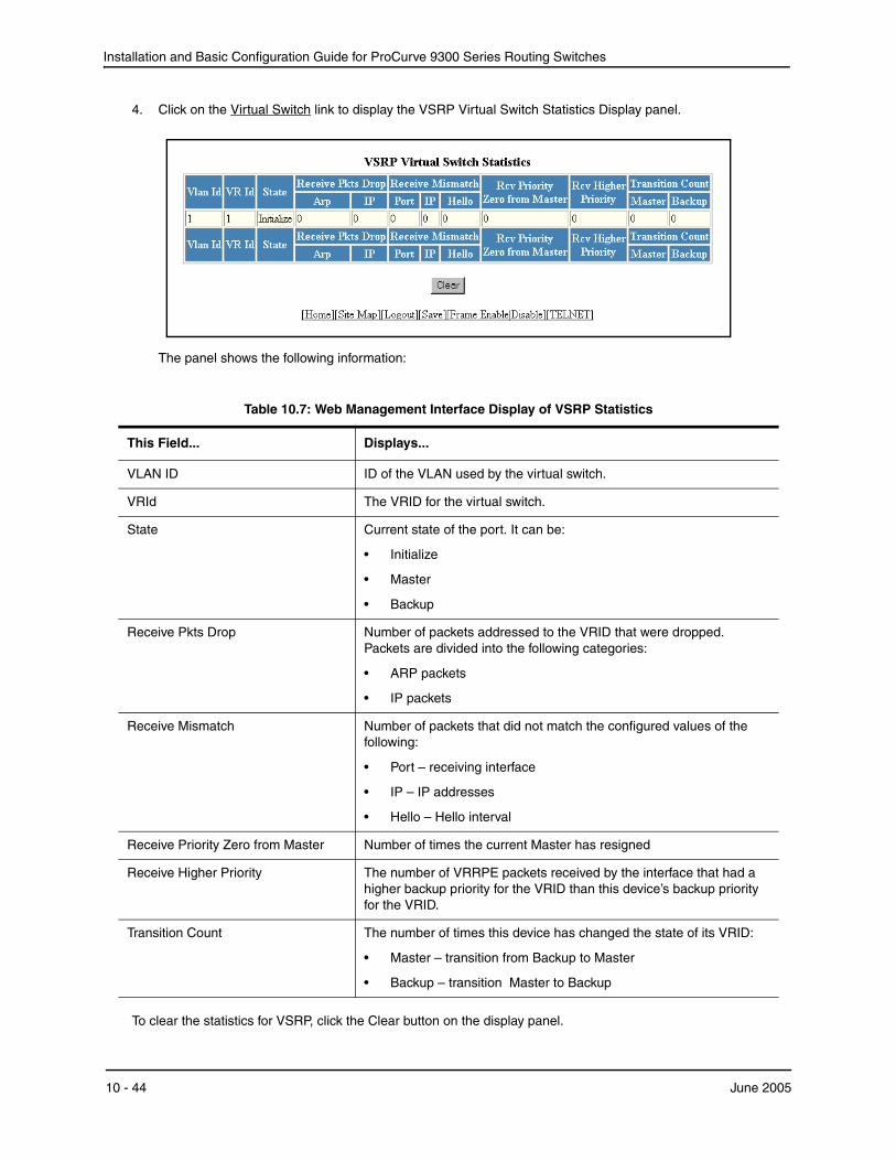
Installation and Basic Configuration Guide for ProCurve 9300 Series Routing Switches
4. Click on the Virtual Switch link to display the VSRP Virtual Switch Statistics Display panel.
The panel shows the following information:
Table 10.7: Web Management Interface Display of VSRP Statistics
This Field... Displays...
VLAN ID ID of the VLAN used by the virtual switch.
VRId The VRID for the virtual switch.
State Current state of the port. It can be:
• Initialize
• Master
• Backup
Receive Pkts Drop Number of packets addressed to the VRID that were dropped. Packets are divided into the following categories:
• ARP packets
• IP packets
Receive Mismatch Number of packets that did not match the configured values of the following:
• Port – receiving interface
• IP – IP addresses
• Hello – Hello interval
Receive Priority Zero from Master Number of times the current Master has resigned
Receive Higher Priority The number of VRRPE packets received by the interface that had a higher backup priority for the VRID than this device’s backup priority for the VRID.
Transition Count The number of times this device has changed the state of its VRID:
• Master – transition from Backup to Master
• Backup – transition Master to Backup
To clear the statistics for VSRP, click the Clear button on the display panel.
10 - 44 June 2005

Configuring Metro Features
June 2005 10 - 45

Installation and Basic Configuration Guide for ProCurve 9300 Series Routing Switches
10 - 46 June 2005
Chapter 11Configuring Virtual LANs (VLANs)
This chapter describes how to configure Virtual LANs (VLANs) on ProCurve Routing Switches.
The “Overview” section provides basic information about HP’s VLAN options. Following this section, other sections provide configuration procedures and examples.
To display configuration information for VLANs, see “Displaying VLAN Information” on page 11-63.
For complete syntax information for the CLI commands shown in this chapter, see the Command Line Interface Reference for ProCurve 9300/9400 Series Routing Switches.
Most of the configuration examples in this chapter are based on CLI commands. For Web management procedures, see “Configuring VLANs Using the Web Management Interface” on page 11-57.
NOTE: For information about the GARP VLAN Registration Protocol (GVRP), see “Configuring GARP VLAN Registration Protocol (GVRP)” on page 13-1.
OverviewThis section describes the HP VLAN features. Configuration procedures and examples appear in later sections of this chapter.
Types of VLANsYou can configure the following types of VLANs on HP devices.
• Layer 2 port-based VLAN – a set of physical ports that share a common, exclusive Layer 2 broadcast domain
• Layer 3 protocol VLANs – a subset of ports within a port-based VLAN that share a common, exclusive broadcast domain for Layer 3 broadcasts of the specified protocol type
• IP subnet VLANs – a subset of ports in a port-based VLAN that share a common, exclusive subnet broadcast domain for a specified IP subnet
• IPX network VLANs – a subset of ports in a port-based VLAN that share a common, exclusive network broadcast domain for a specified IPX network
• AppleTalk cable VLANs – a subset of ports in a port-based VLAN that share a common, exclusive network broadcast domain for a specified AppleTalk cable range
When an HP device receives a packet on a port that is a member of a VLAN, the device forwards the packet based on the following VLAN hierarchy:
June 2005 11 - 1
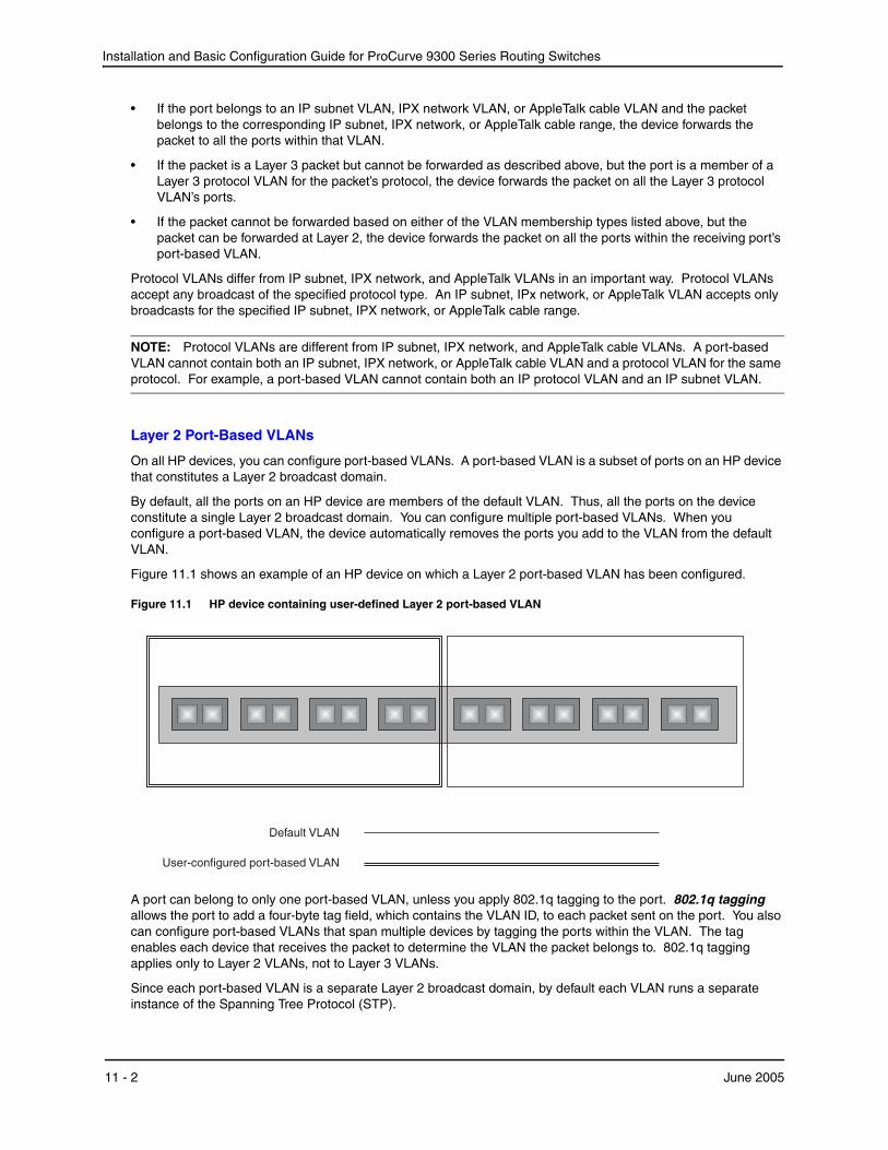
Installation and Basic Configuration Guide for ProCurve 9300 Series Routing Switches
• If the port belongs to an IP subnet VLAN, IPX network VLAN, or AppleTalk cable VLAN and the packet belongs to the corresponding IP subnet, IPX network, or AppleTalk cable range, the device forwards the packet to all the ports within that VLAN.
• If the packet is a Layer 3 packet but cannot be forwarded as described above, but the port is a member of a Layer 3 protocol VLAN for the packet’s protocol, the device forwards the packet on all the Layer 3 protocol VLAN’s ports.
• If the packet cannot be forwarded based on either of the VLAN membership types listed above, but the packet can be forwarded at Layer 2, the device forwards the packet on all the ports within the receiving port’s port-based VLAN.
Protocol VLANs differ from IP subnet, IPX network, and AppleTalk VLANs in an important way. Protocol VLANs accept any broadcast of the specified protocol type. An IP subnet, IPx network, or AppleTalk VLAN accepts only broadcasts for the specified IP subnet, IPX network, or AppleTalk cable range.
NOTE: Protocol VLANs are different from IP subnet, IPX network, and AppleTalk cable VLANs. A port-based VLAN cannot contain both an IP subnet, IPX network, or AppleTalk cable VLAN and a protocol VLAN for the same protocol. For example, a port-based VLAN cannot contain both an IP protocol VLAN and an IP subnet VLAN.
Layer 2 Port-Based VLANs
On all HP devices, you can configure port-based VLANs. A port-based VLAN is a subset of ports on an HP device that constitutes a Layer 2 broadcast domain.
By default, all the ports on an HP device are members of the default VLAN. Thus, all the ports on the device constitute a single Layer 2 broadcast domain. You can configure multiple port-based VLANs. When you configure a port-based VLAN, the device automatically removes the ports you add to the VLAN from the default VLAN.
Figure 11.1 shows an example of an HP device on which a Layer 2 port-based VLAN has been configured.
Figure 11.1 HP device containing user-defined Layer 2 port-based VLAN
Default VLAN
User-configured port-based VLAN
A port can belong to only one port-based VLAN, unless you apply 802.1q tagging to the port. 802.1q tagging allows the port to add a four-byte tag field, which contains the VLAN ID, to each packet sent on the port. You also can configure port-based VLANs that span multiple devices by tagging the ports within the VLAN. The tag enables each device that receives the packet to determine the VLAN the packet belongs to. 802.1q tagging applies only to Layer 2 VLANs, not to Layer 3 VLANs.
Since each port-based VLAN is a separate Layer 2 broadcast domain, by default each VLAN runs a separate instance of the Spanning Tree Protocol (STP).
11 - 2 June 2005

Configuring Virtual LANs (VLANs)
Layer 2 traffic is bridged within a port-based VLAN and Layer 2 broadcasts are sent to all the ports within the VLAN.
Layer 3 Protocol-Based VLANs
If you want some or all of the ports within a port-based VLAN to be organized according to Layer 3 protocol, you must configure a Layer 3 protocol-based VLAN within the port-based VLAN.
You can configure each of the following types of protocol-based VLAN within a port-based VLAN. All the ports in the Layer 3 VLAN must be in the same Layer 2 VLAN.
• AppleTalk – The device sends AppleTalk broadcasts to all ports within the AppleTalk protocol VLAN.
• IP – The device sends IP broadcasts to all ports within the IP protocol VLAN.
• IPX – The device sends IPX broadcasts to all ports within the IPX protocol VLAN.
• DECnet – The device sends DECnet broadcasts to all ports within the DECnet protocol VLAN.
• NetBIOS – The device sends NetBIOS broadcasts to all ports within the NetBIOS protocol VLAN.
• Other – The device sends broadcasts for all protocol types other than those listed above to all ports within the VLAN.
Figure 11.2 shows an example of Layer 3 protocol VLANs configured within a Layer 2 port-based VLAN.
Figure 11.2 Layer 3 protocol VLANs within a Layer 2 port-based VLAN
Default VLAN
User-configured port-based VLAN
Protocol VLAN, IP sub-net VLAN,IPX network VLANor AppleTalk VLAN
Integrated Switch Routing (ISR)
Hewlett-Packard’ Integrated Switch Routing (ISR) feature enables VLANs configured on Routing Switches to route Layer 3 traffic from one protocol VLAN or IP subnet, IPX network, or AppleTalk cable VLAN to another. Normally, to route traffic from one IP subnet, IPX network, or AppleTalk cable VLAN to another, you would need to forward the traffic to an external Routing Switch. The VLANs provide Layer 3 broadcast domains for these protocols but do not in themselves provide routing services for these protocols. This is true even if the source and destination IP subnets, IPX networks, or AppleTalk cable ranges are on the same device.
ISR eliminates the need for an external Routing Switch by allowing you to route between VLANs using virtual routing interfaces (ves). A virtual routing interface is a logical port on which you can configure Layer 3 routing parameters. You configure a separate virtual routing interface on each VLAN that you want to be able to route from or to. For example, if you configure two IP subnet VLANs on a Routing Switch, you can configure a virtual
June 2005 11 - 3
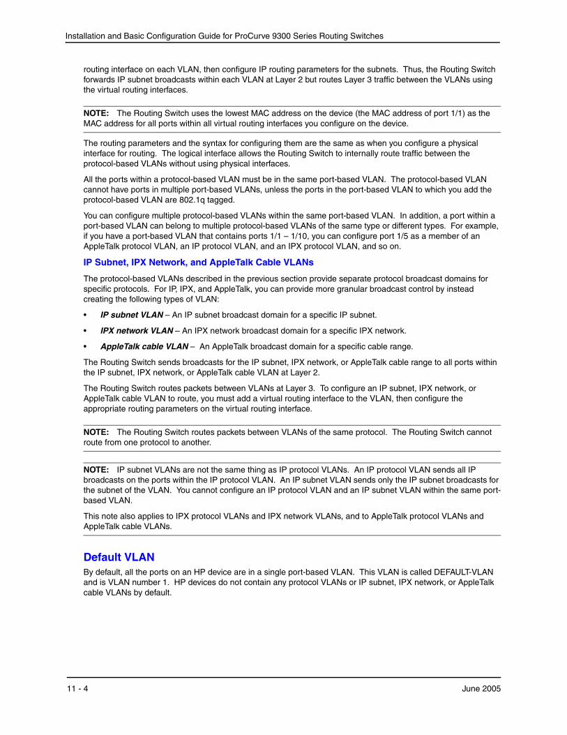
Installation and Basic Configuration Guide for ProCurve 9300 Series Routing Switches
routing interface on each VLAN, then configure IP routing parameters for the subnets. Thus, the Routing Switch forwards IP subnet broadcasts within each VLAN at Layer 2 but routes Layer 3 traffic between the VLANs using the virtual routing interfaces.
NOTE: The Routing Switch uses the lowest MAC address on the device (the MAC address of port 1/1) as the MAC address for all ports within all virtual routing interfaces you configure on the device.
The routing parameters and the syntax for configuring them are the same as when you configure a physical interface for routing. The logical interface allows the Routing Switch to internally route traffic between the protocol-based VLANs without using physical interfaces.
All the ports within a protocol-based VLAN must be in the same port-based VLAN. The protocol-based VLAN cannot have ports in multiple port-based VLANs, unless the ports in the port-based VLAN to which you add the protocol-based VLAN are 802.1q tagged.
You can configure multiple protocol-based VLANs within the same port-based VLAN. In addition, a port within a port-based VLAN can belong to multiple protocol-based VLANs of the same type or different types. For example, if you have a port-based VLAN that contains ports 1/1 – 1/10, you can configure port 1/5 as a member of an AppleTalk protocol VLAN, an IP protocol VLAN, and an IPX protocol VLAN, and so on.
IP Subnet, IPX Network, and AppleTalk Cable VLANs
The protocol-based VLANs described in the previous section provide separate protocol broadcast domains for specific protocols. For IP, IPX, and AppleTalk, you can provide more granular broadcast control by instead creating the following types of VLAN:
• IP subnet VLAN – An IP subnet broadcast domain for a specific IP subnet.
• IPX network VLAN – An IPX network broadcast domain for a specific IPX network.
• AppleTalk cable VLAN – An AppleTalk broadcast domain for a specific cable range.
The Routing Switch sends broadcasts for the IP subnet, IPX network, or AppleTalk cable range to all ports within the IP subnet, IPX network, or AppleTalk cable VLAN at Layer 2.
The Routing Switch routes packets between VLANs at Layer 3. To configure an IP subnet, IPX network, or AppleTalk cable VLAN to route, you must add a virtual routing interface to the VLAN, then configure the appropriate routing parameters on the virtual routing interface.
NOTE: The Routing Switch routes packets between VLANs of the same protocol. The Routing Switch cannot route from one protocol to another.
NOTE: IP subnet VLANs are not the same thing as IP protocol VLANs. An IP protocol VLAN sends all IP broadcasts on the ports within the IP protocol VLAN. An IP subnet VLAN sends only the IP subnet broadcasts for the subnet of the VLAN. You cannot configure an IP protocol VLAN and an IP subnet VLAN within the same port-based VLAN.
This note also applies to IPX protocol VLANs and IPX network VLANs, and to AppleTalk protocol VLANs and AppleTalk cable VLANs.
Default VLANBy default, all the ports on an HP device are in a single port-based VLAN. This VLAN is called DEFAULT-VLAN and is VLAN number 1. HP devices do not contain any protocol VLANs or IP subnet, IPX network, or AppleTalk cable VLANs by default.
11 - 4 June 2005
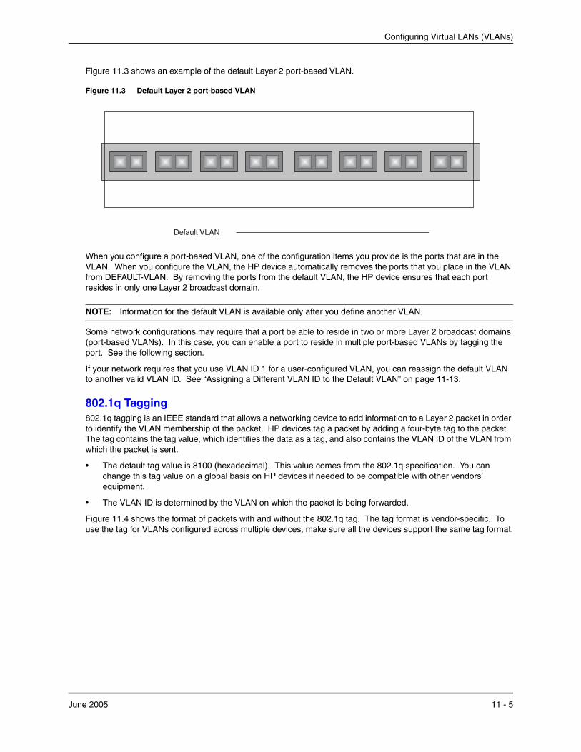
Configuring Virtual LANs (VLANs)
Figure 11.3 shows an example of the default Layer 2 port-based VLAN.
Figure 11.3 Default Layer 2 port-based VLAN
Default VLAN
When you configure a port-based VLAN, one of the configuration items you provide is the ports that are in the VLAN. When you configure the VLAN, the HP device automatically removes the ports that you place in the VLAN from DEFAULT-VLAN. By removing the ports from the default VLAN, the HP device ensures that each port resides in only one Layer 2 broadcast domain.
NOTE: Information for the default VLAN is available only after you define another VLAN.
Some network configurations may require that a port be able to reside in two or more Layer 2 broadcast domains (port-based VLANs). In this case, you can enable a port to reside in multiple port-based VLANs by tagging the port. See the following section.
If your network requires that you use VLAN ID 1 for a user-configured VLAN, you can reassign the default VLAN to another valid VLAN ID. See “Assigning a Different VLAN ID to the Default VLAN” on page 11-13.
802.1q Tagging802.1q tagging is an IEEE standard that allows a networking device to add information to a Layer 2 packet in order to identify the VLAN membership of the packet. HP devices tag a packet by adding a four-byte tag to the packet. The tag contains the tag value, which identifies the data as a tag, and also contains the VLAN ID of the VLAN from which the packet is sent.
• The default tag value is 8100 (hexadecimal). This value comes from the 802.1q specification. You can change this tag value on a global basis on HP devices if needed to be compatible with other vendors’ equipment.
• The VLAN ID is determined by the VLAN on which the packet is being forwarded.
Figure 11.4 shows the format of packets with and without the 802.1q tag. The tag format is vendor-specific. To use the tag for VLANs configured across multiple devices, make sure all the devices support the same tag format.
June 2005 11 - 5
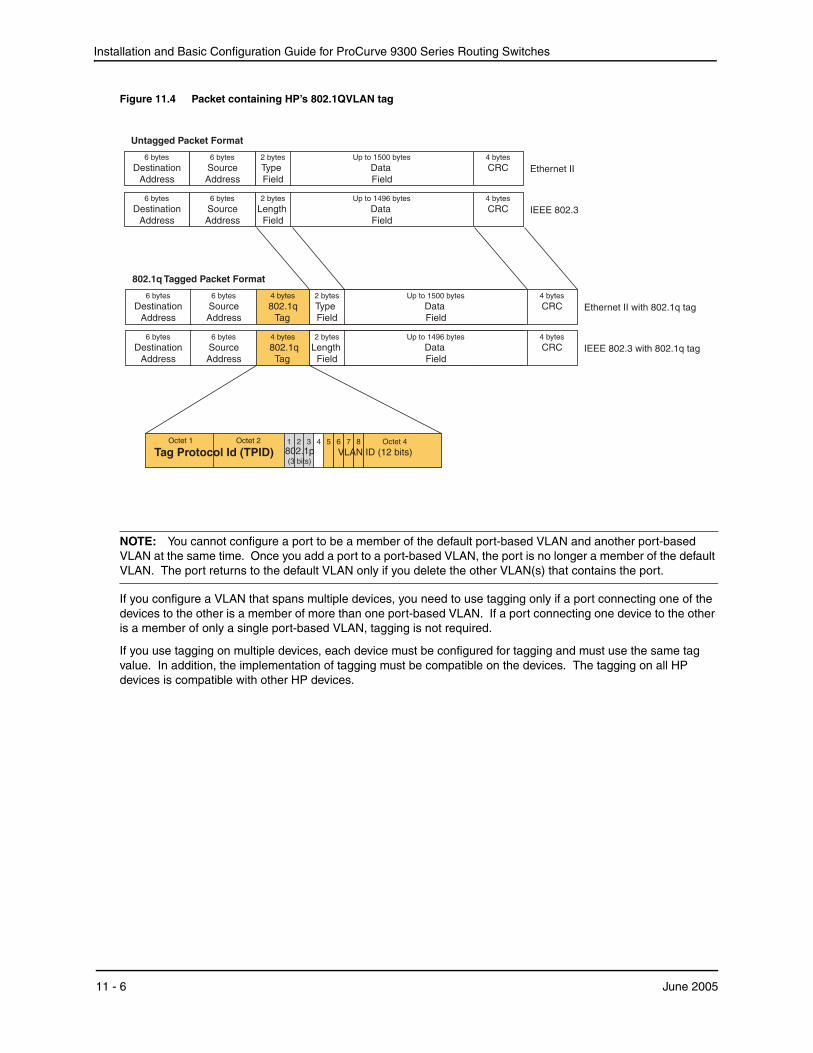
Installation and Basic Configuration Guide for ProCurve 9300 Series Routing Switches
Figure 11.4 Packet containing HP’s 802.1QVLAN tag
6 bytes
DestinationAddress
2 bytes
LengthField
Up to 1496 bytes
DataField
4 bytes
CRC IEEE 802.3
6 bytes
SourceAddress
6 bytes
DestinationAddress
2 bytes
TypeField
Up to 1500 bytes
DataField
4 bytes
CRC Ethernet II6 bytes
SourceAddress
2 bytes
LengthField
Up to 1496 bytes
DataField
4 bytes
CRC IEEE 802.3 with 802.1q tag
2 bytes
TypeField
Up to 1500 bytes
DataField
4 bytes
CRC Ethernet II with 802.1q tag
4 bytes
802.1qTag
4 bytes
802.1qTag
802.1q Tagged Packet Format
Octet 1 Octet 2
Tag Protocol Id (TPID)5 6 7 8 Octet 4
VLAN ID (12 bits)1 2 3 4802.1p(3 bits)
6 bytes
DestinationAddress
2 bytes
LengthField
Up to 1496 bytes
DataField
4 bytes
CRC IEEE 802.36 bytes
SourceAddress
6 bytes
DestinationAddress
2 bytes
TypeField
Up to 1500 bytes
DataField
4 bytes
CRC Ethernet II6 bytes
SourceAddress
Untagged Packet Format
NOTE: You cannot configure a port to be a member of the default port-based VLAN and another port-based VLAN at the same time. Once you add a port to a port-based VLAN, the port is no longer a member of the default VLAN. The port returns to the default VLAN only if you delete the other VLAN(s) that contains the port.
If you configure a VLAN that spans multiple devices, you need to use tagging only if a port connecting one of the devices to the other is a member of more than one port-based VLAN. If a port connecting one device to the other is a member of only a single port-based VLAN, tagging is not required.
If you use tagging on multiple devices, each device must be configured for tagging and must use the same tag value. In addition, the implementation of tagging must be compatible on the devices. The tagging on all HP devices is compatible with other HP devices.
11 - 6 June 2005
Configuring Virtual LANs (VLANs)
Figure 11.5 shows an example of two devices that have the same Layer 2 port-based VLANs configured across them. Notice that only one of the VLANs requires tagging.
Figure 11.5 VLANs configured across multiple devices
User-configured port-based VLAN
VLAN A VLAN A/B VLAN B
VLAN A VLAN A/B VLAN B
Segment 1
Segment 2
Spanning Tree Protocol (STP)STP is disabled by default on ProCurve Routing Switches.
Also by default, each port-based VLAN has a separate instance of STP. Thus, when STP is globally enabled, each port-based VLAN on the device runs a separate spanning tree.
You can enable or disable STP on the following levels:
• Globally – Affects all ports on the device.
NOTE: If you configure a port-based VLAN on the device, the VLAN has the same STP state as the default STP state on the device. On Routing Switches, new VLANs have STP disabled by default. You can enable or disable STP in each VLAN separately. In addition, you can enable or disable STP on individual ports.
• Port-based VLAN – Affects all ports within the specified port-based VLAN.
STP is a Layer 2 protocol. Thus, you cannot enable or disable STP for individual protocol VLANs or for IP subnet, IPX network, or AppleTalk cable VLANs. The STP state of a port-based VLAN containing these other types of VLANs determines the STP state for all the Layer 2 broadcasts within the port-based VLAN. This is true even though Layer 3 protocol broadcasts are sent on Layer 2 within the VLAN.
It is possible that STP will block one or more ports in a protocol VLAN that uses a virtual routing interface to route to other VLANs. For IP protocol and IP subnet VLANs, even though some of the physical ports of the virtual routing interface are blocked, the virtual routing interface can still route so long as at least one port in the virtual routing interface’s protocol VLAN is not blocked by STP.
June 2005 11 - 7
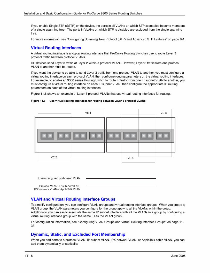
Installation and Basic Configuration Guide for ProCurve 9300 Series Routing Switches
If you enable Single STP (SSTP) on the device, the ports in all VLANs on which STP is enabled become members of a single spanning tree. The ports in VLANs on which STP is disabled are excluded from the single spanning tree.
For more information, see “Configuring Spanning Tree Protocol (STP) and Advanced STP Features” on page 8-1.
Virtual Routing InterfacesA virtual routing interface is a logical routing interface that ProCurve Routing Switches use to route Layer 3 protocol traffic between protocol VLANs.
HP devices send Layer 3 traffic at Layer 2 within a protocol VLAN. However, Layer 3 traffic from one protocol VLAN to another must be routed.
If you want the device to be able to send Layer 3 traffic from one protocol VLAN to another, you must configure a virtual routing interface on each protocol VLAN, then configure routing parameters on the virtual routing interfaces. For example, to enable an 9300 series Routing Switch to route IP traffic from one IP subnet VLAN to another, you must configure a virtual routing interface on each IP subnet VLAN, then configure the appropriate IP routing parameters on each of the virtual routing interfaces.
Figure 11.6 shows an example of Layer 3 protocol VLANs that use virtual routing interfaces for routing.
Figure 11.6 Use virtual routing interfaces for routing between Layer 3 protocol VLANs
User-configured port-based VLAN
Protocol VLAN, IP sub-net VLAN,IPX network VLANor AppleTalk VLAN
VE 2
VE 1
VE 4
VE 3
VLAN and Virtual Routing Interface GroupsTo simplify configuration, you can configure VLAN groups and virtual routing interface groups. When you create a VLAN group, the VLAN parameters you configure for the group apply to all the VLANs within the group. Additionally, you can easily associate the same IP subnet interface with all the VLANs in a group by configuring a virtual routing interface group with the same ID as the VLAN group.
For configuration information, see “Configuring VLAN Groups and Virtual Routing Interface Groups” on page 11-38.
Dynamic, Static, and Excluded Port MembershipWhen you add ports to a protocol VLAN, IP subnet VLAN, IPX network VLAN, or AppleTalk cable VLAN, you can add them dynamically or statically:
11 - 8 June 2005
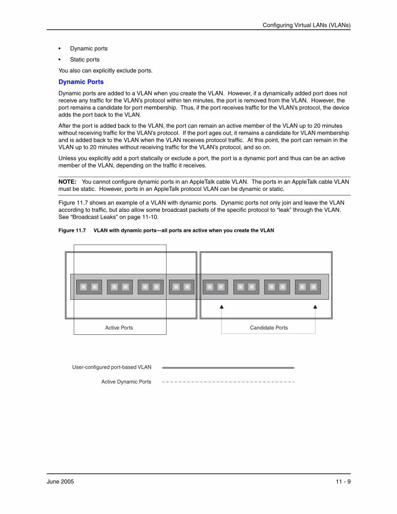
Configuring Virtual LANs (VLANs)
• Dynamic ports
• Static ports
You also can explicitly exclude ports.
Dynamic Ports
Dynamic ports are added to a VLAN when you create the VLAN. However, if a dynamically added port does not receive any traffic for the VLAN’s protocol within ten minutes, the port is removed from the VLAN. However, the port remains a candidate for port membership. Thus, if the port receives traffic for the VLAN’s protocol, the device adds the port back to the VLAN.
After the port is added back to the VLAN, the port can remain an active member of the VLAN up to 20 minutes without receiving traffic for the VLAN’s protocol. If the port ages out, it remains a candidate for VLAN membership and is added back to the VLAN when the VLAN receives protocol traffic. At this point, the port can remain in the VLAN up to 20 minutes without receiving traffic for the VLAN’s protocol, and so on.
Unless you explicitly add a port statically or exclude a port, the port is a dynamic port and thus can be an active member of the VLAN, depending on the traffic it receives.
NOTE: You cannot configure dynamic ports in an AppleTalk cable VLAN. The ports in an AppleTalk cable VLAN must be static. However, ports in an AppleTalk protocol VLAN can be dynamic or static.
Figure 11.7 shows an example of a VLAN with dynamic ports. Dynamic ports not only join and leave the VLAN according to traffic, but also allow some broadcast packets of the specific protocol to “leak” through the VLAN. See “Broadcast Leaks” on page 11-10.
Figure 11.7 VLAN with dynamic ports—all ports are active when you create the VLAN
User-configured port-based VLAN
Active Dynamic Ports
Active Ports Candidate Ports
June 2005 11 - 9
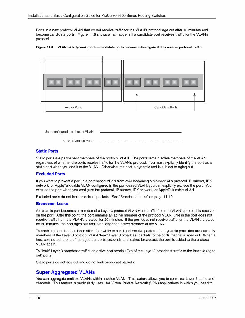
Installation and Basic Configuration Guide for ProCurve 9300 Series Routing Switches
Ports in a new protocol VLAN that do not receive traffic for the VLAN’s protocol age out after 10 minutes and become candidate ports. Figure 11.8 shows what happens if a candidate port receives traffic for the VLAN’s protocol.
Figure 11.8 VLAN with dynamic ports—candidate ports become active again if they receive protocol traffic
User-configured port-based VLAN
Active Dynamic Ports
Active Ports Candidate Ports
Static Ports
Static ports are permanent members of the protocol VLAN. The ports remain active members of the VLAN regardless of whether the ports receive traffic for the VLAN’s protocol. You must explicitly identify the port as a static port when you add it to the VLAN. Otherwise, the port is dynamic and is subject to aging out.
Excluded Ports
If you want to prevent a port in a port-based VLAN from ever becoming a member of a protocol, IP subnet, IPX network, or AppleTalk cable VLAN configured in the port-based VLAN, you can explicitly exclude the port. You exclude the port when you configure the protocol, IP subnet, IPX network, or AppleTalk cable VLAN.
Excluded ports do not leak broadcast packets. See “Broadcast Leaks” on page 11-10.
Broadcast Leaks
A dynamic port becomes a member of a Layer 3 protocol VLAN when traffic from the VLAN's protocol is received on the port. After this point, the port remains an active member of the protocol VLAN, unless the port does not receive traffic from the VLAN's protocol for 20 minutes. If the port does not receive traffic for the VLAN's protocol for 20 minutes, the port ages out and is no longer an active member of the VLAN.
To enable a host that has been silent for awhile to send and receive packets, the dynamic ports that are currently members of the Layer 3 protocol VLAN "leak" Layer 3 broadcast packets to the ports that have aged out. When a host connected to one of the aged out ports responds to a leaked broadcast, the port is added to the protocol VLAN again.
To "leak" Layer 3 broadcast traffic, an active port sends 1/8th of the Layer 3 broadcast traffic to the inactive (aged out) ports.
Static ports do not age out and do not leak broadcast packets.
Super Aggregated VLANsYou can aggregate multiple VLANs within another VLAN. This feature allows you to construct Layer 2 paths and channels. This feature is particularly useful for Virtual Private Network (VPN) applications in which you need to
11 - 10 June 2005
Configuring Virtual LANs (VLANs)
provide a private, dedicated Ethernet connection for an individual client to transparently reach its subnet across multiple networks.
For an application example and configuration information, see “Configuring Super Aggregated VLANs” on page 11-42.
Trunk Group Ports and VLAN MembershipA trunk group is a set of physical ports that are configured to act as a single physical interface. Each trunk group’s port configuration is based on the configuration of the lead port, which is the lowest numbered port in the group.
If you add a trunk group’s lead port to a VLAN, all of the ports in the trunk group become members of that VLAN.
Summary of VLAN Configuration RulesA hierarchy of VLANs exists between the Layer 2 and Layer 3 protocol-based VLANs:
• Port-based VLANs are at the lowest level of the hierarchy.
• Layer 3 protocol-based VLANs, IP, IPX, AppleTalk, Decnet, and NetBIOS are at the middle level of the hierarchy.
• IP subnet, IPX network, and AppleTalk cable VLANs are at the top of the hierarchy.
NOTE: You cannot have a protocol-based VLAN and a subnet or network VLAN of the same protocol type in the same port-based VLAN. For example, you can have an IPX protocol VLAN and IP subnet VLAN in the same port-based VLAN, but you cannot have an IP protocol VLAN and an IP subnet VLAN in the same port-based VLAN, nor can you have an IPX protocol VLAN and an IPX network VLAN in the same port-based VLAN.
As an HP device receives packets, the VLAN classification starts from the highest level VLAN first. Therefore, if an interface is configured as a member of both a port-based VLAN and an IP protocol VLAN, IP packets coming into the interface are classified as members of the IP protocol VLAN because that VLAN is higher in the VLAN hierarchy.
Multiple VLAN Membership Rules
• A port can belong to multiple, unique, overlapping Layer 3 protocol-based VLANs without VLAN tagging.
• A port can belong to multiple, overlapping Layer 2 port-based VLANs only if the port is a tagged port. Packets sent out of a tagged port use an 802.1q-tagged frame.
• When both port and protocol-based VLANs are configured on a given device, all protocol VLANs must be strictly contained within a port-based VLAN. A protocol VLAN cannot include ports from multiple port-based VLANs. This rule is required to ensure that port-based VLANs remain loop-free Layer 2 broadcast domains.
• IP protocol VLANs and IP subnet VLANs cannot operate concurrently on the system or within the same port-based VLAN.
• IPX protocol VLANs and IPX network VLANs cannot operate concurrently on the system or within the same port-based VLAN.
• If you first configure IP and IPX protocol VLANs before deciding to partition the network by IP subnet and IPX network VLANs, then you need to delete those VLANs before creating the IP subnet and IPX network VLANs.
• Removing a configured port-based VLAN from a Hewlett-Packard Routing Switch automatically removes any protocol-based VLAN, IP subnet VLAN, AppleTalk cable VLAN, or IPX network VLAN, or any Virtual Ethernet router interfaces defined within the Port-based VLAN.
Routing Between VLANsProCurve Routing Switches can locally route IP, IPX, and Appletalk between VLANs defined within a single Routing Switch. All other routable protocols or protocol VLANs (for example, DecNet) must be routed by another external Routing Switch capable of routing the protocol.
June 2005 11 - 11
Installation and Basic Configuration Guide for ProCurve 9300 Series Routing Switches
Virtual Routing Interfaces You need to configure virtual routing interfaces if an IP, IPX, or Appletalk protocol VLAN, IP subnet VLAN, AppleTalk cable VLAN, or IPX network VLAN needs to route protocols to another port-based VLAN on the same Routing Switch. A virtual routing interface can be associated with the ports in only a single port-based VLAN. Virtual router interfaces must be defined at the highest level of the VLAN hierarchy.
If you do not need to further partition the port-based VLAN by defining separate Layer 3 VLANs, you can define a single virtual routing interface at the port-based VLAN level and enable IP, IPX, and Appletalk routing on a single virtual routing interface.
Bridging and Routing the Same Protocol Simultaneously on the Same DeviceSome configurations may require simultaneous switching and routing of the same single protocol across different sets of ports on the same Routing Switch. When IP, IPX, or Appletalk routing is enabled on a ProCurve Routing Switch, you can route these protocols on specific interfaces while bridging them on other interfaces. In this scenario, you can create two separate backbones for the same protocol, one bridged and one routed.
To bridge IP, IPX, or Appletalk at the same time these protocols are being routed, you need to configure an IP protocol, IP subnet, IPX protocol, IPX network, or Appletalk protocol VLAN and not assign a virtual routing interface to the VLAN. Packets for these protocols are bridged or switched at Layer 2 across ports on the Routing Switch that are included in the Layer 3 VLAN. If these VLANs are built within port-based VLANs, they can be tagged across a single set of backbone fibers to create separate Layer 2 switched and Layer 3 routed backbones for the same protocol on a single physical backbone.
Routing Between VLANs Using Virtual Routing InterfacesHP calls the ability to route between VLANs with virtual routing interfaces Integrated Switch Routing (ISR). There are some important concepts to understand before designing an ISR backbone.
Virtual router interfaces can be defined on port-based, IP protocol, IP subnet, IPX protocol, IPX network, AppleTalk protocol, and AppleTalk cable VLANs.
To create any type of VLAN on a ProCurve Routing Switch, Layer 2 forwarding must be enabled. When Layer 2 forwarding is enabled, the Routing Switch becomes a Switch on all ports for all non-routable protocols.
If the router interfaces for IP, IPX, or AppleTalk are configured on physical ports, then routing occurs independent of the Spanning Tree Protocol (STP). However, if the router interfaces are defined for any type VLAN, they are virtual routing interfaces and are subject to the rules of STP.
If your backbone is consisted of virtual routing interfaces all within the same STP domain, it is a bridged backbone, not a routed one. This means that the set of backbone interfaces that are blocked by STP will be blocked for routed protocols as well. The routed protocols will be able to cross these paths only when the STP state of the link is FORWARDING. This problem is easily avoided by proper network design.
When designing an ISR network, pay attention to your use of virtual routing interfaces and the spanning-tree domain. Full backbone routing can be achieved by configuring routing on each physical interface that connects to the backbone. Routing is independent of STP when configured on a physical interface.
If your ISR design requires that you switch IP, IPX, or Appletalk at Layer 2 while simultaneously routing the same protocols over a single backbone, then create multiple port-based VLANs and use VLAN tagging on the backbone links to separate your Layer 2 switched and Layer 3 routed networks.
There is a separate STP domain for each port-based VLAN. Routing occurs independently across port-based VLANs or STP domains. You can define each end of each backbone link as a separate tagged port-based VLAN. Routing will occur independently across the port-based VLANs. Because each port-based VLAN’s STP domain is a single point-to-point backbone connection, you are guaranteed to never have an STP loop. STP will never block the virtual router interfaces within the tagged port-based VLAN, and you will have a fully routed backbone.
11 - 12 June 2005
Configuring Virtual LANs (VLANs)
Dynamic Port AssignmentAll switch ports are dynamically assigned to any non-routable VLAN on ProCurve Routing Switches. To maintain explicit control of the VLAN, you can explicitly exclude ports when configuring any non-routable Layer 3 VLAN on a ProCurve Routing Switch.
If you do not want the ports to have dynamic membership, you can add them statically. This eliminates the need to explicitly exclude the ports that you do not want to participate in a particular Layer 3 VLAN.
Assigning a Different VLAN ID to the Default VLANWhen you enable port-based VLANs, all ports in the system are added to the default VLAN. By default, the default VLAN ID is “VLAN 1”. The default VLAN is not configurable. If you want to use the VLAN ID “VLAN 1” as a configurable VLAN, you can assign a different VLAN ID to the default VLAN.
To reassign the default VLAN to a different VLAN ID, enter the following command:
ProCurveRS(config)# default-vlan-id 4095
Syntax: [no] default-vlan-d <vlan-id>
You must specify a valid VLAN ID that is not already in use. For example, if you have already defined VLAN 10, do not try to use “10” as the new VLAN ID for the default VLAN. Valid VLAN IDs are numbers from 1 – 4096.
NOTE: Changing the default VLAN name does not change the properties of the default VLAN. Changing the name allows you to use the VLAN ID “1” as a configurable VLAN.
Assigning Trunk Group PortsWhen a “lead” trunk group port is assigned to a VLAN, all other members of the trunk group are automatically added to that VLAN. A lead port is the first port of a trunk group port range; for example, “1” in 1 – 4 or “5” in 5 – 8. See “Trunk Group Rules” in the Installation and Basic Configuration Guide for ProCurve 9300 Series Routing Switches for more information.
Configuring Port-Based VLANsPort-based VLANs allow you to provide separate spanning tree protocol (STP) domains or broadcast domains on a port-by-port basis.
This section describes how to perform the following tasks for port-based VLANs using the CLI:
• Create a VLAN.
• Delete a VLAN.
• Modify a VLAN.
• Assign a higher priority to the VLAN.
• Change a VLAN’s priority.
• Enable or disable STP on the VLAN.
EXAMPLE:
Figure 11.9 shows a simple port-based VLAN configuration using a single ProCurve Routing Switch. All ports within each VLAN are untagged. One untagged port within each VLAN is used to connect the Routing Switch to another Routing Switch (in this example, an 9308M) for Layer 3 connectivity between the two port-based VLANs.
June 2005 11 - 13
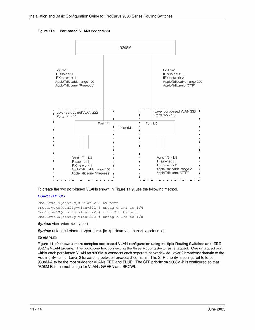
Installation and Basic Configuration Guide for ProCurve 9300 Series Routing Switches
Figure 11.9 Port-based VLANs 222 and 333
Port 1/2IP sub-net 2IPX network 2AppleTalk cable range 200AppleTalk zone “CTP”
9308M
Ports 1/6 - 1/8IP sub-net 2IPX network 2AppleTalk cable range 2AppleTalk zone “CTP”
9308M
Port 1/1IP sub-net 1IPX network 1AppleTalk cable range 100AppleTalk zone “Prepress”
Layer port-based VLAN 333Ports 1/5 - 1/8
Port 1/5
Layer port-based VLAN 222Ports 1/1 - 1/4
Ports 1/2 - 1/4IP sub-net 1IPX network 1AppleTalk cable range 100AppleTalk zone “Prepress”
Port 1/1
To create the two port-based VLANs shown in Figure 11.9, use the following method.
USING THE CLI
ProCurveRS(config)# vlan 222 by port ProCurveRS(config-vlan-222)# untag e 1/1 to 1/4 ProCurveRS(config-vlan-222)# vlan 333 by port ProCurveRS(config-vlan-333)# untag e 1/5 to 1/8
Syntax: vlan <vlan-id> by port
Syntax: untagged ethernet <portnum> [to <portnum> | ethernet <portnum>]
EXAMPLE:
Figure 11.10 shows a more complex port-based VLAN configuration using multiple Routing Switches and IEEE 802.1q VLAN tagging. The backbone link connecting the three Routing Switches is tagged. One untagged port within each port-based VLAN on 9308M-A connects each separate network wide Layer 2 broadcast domain to the Routing Switch for Layer 3 forwarding between broadcast domains. The STP priority is configured to force 9308M-A to be the root bridge for VLANs RED and BLUE. The STP priority on 9308M-B is configured so that 9308M-B is the root bridge for VLANs GREEN and BROWN.
11 - 14 June 2005
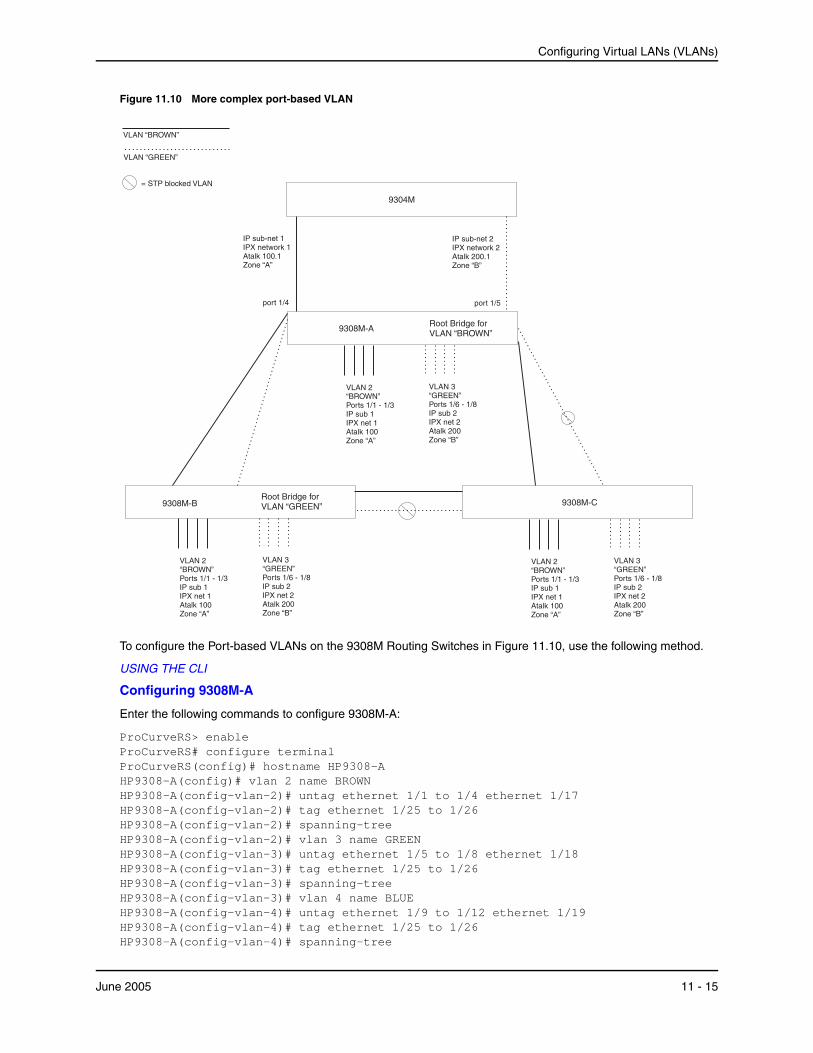
Configuring Virtual LANs (VLANs)
Figure 11.10 More complex port-based VLAN
9308M-C
IP sub-net 2IPX network 2Atalk 200.1Zone “B”
port 1/5
IP sub-net 1IPX network 1Atalk 100.1Zone “A”
9308M-A
VLAN 3“GREEN”Ports 1/6 - 1/8IP sub 2IPX net 2Atalk 200Zone “B”
VLAN 2“BROWN”Ports 1/1 - 1/3IP sub 1IPX net 1Atalk 100Zone “A”
9308M-B
9304M
Root Bridge forVLAN “BROWN”
Root Bridge forVLAN “GREEN”
port 1/4
= STP blocked VLAN
VLAN “BROWN”
VLAN “GREEN”
VLAN 3“GREEN”Ports 1/6 - 1/8IP sub 2IPX net 2Atalk 200Zone “B”
VLAN 2“BROWN”Ports 1/1 - 1/3IP sub 1IPX net 1Atalk 100Zone “A”
VLAN 3“GREEN”Ports 1/6 - 1/8IP sub 2IPX net 2Atalk 200Zone “B”
VLAN 2“BROWN”Ports 1/1 - 1/3IP sub 1IPX net 1Atalk 100Zone “A”
To configure the Port-based VLANs on the 9308M Routing Switches in Figure 11.10, use the following method.
USING THE CLI
Configuring 9308M-A
Enter the following commands to configure 9308M-A:
ProCurveRS> enable ProCurveRS# configure terminal ProCurveRS(config)# hostname HP9308-A HP9308-A(config)# vlan 2 name BROWN HP9308-A(config-vlan-2)# untag ethernet 1/1 to 1/4 ethernet 1/17 HP9308-A(config-vlan-2)# tag ethernet 1/25 to 1/26 HP9308-A(config-vlan-2)# spanning-tree HP9308-A(config-vlan-2)# vlan 3 name GREEN HP9308-A(config-vlan-3)# untag ethernet 1/5 to 1/8 ethernet 1/18 HP9308-A(config-vlan-3)# tag ethernet 1/25 to 1/26 HP9308-A(config-vlan-3)# spanning-tree HP9308-A(config-vlan-3)# vlan 4 name BLUE HP9308-A(config-vlan-4)# untag ethernet 1/9 to 1/12 ethernet 1/19 HP9308-A(config-vlan-4)# tag ethernet 1/25 to 1/26 HP9308-A(config-vlan-4)# spanning-tree
June 2005 11 - 15
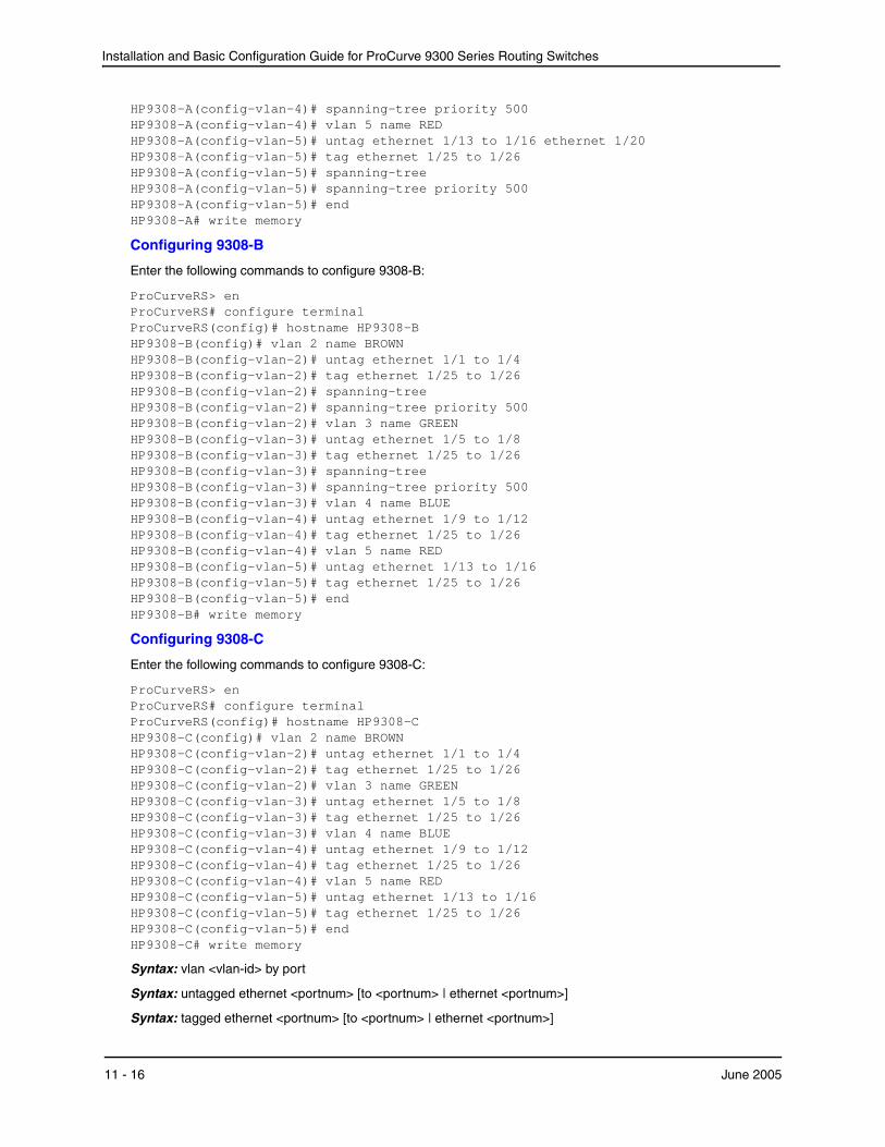
Installation and Basic Configuration Guide for ProCurve 9300 Series Routing Switches
HP9308-A(config-vlan-4)# spanning-tree priority 500 HP9308-A(config-vlan-4)# vlan 5 name RED HP9308-A(config-vlan-5)# untag ethernet 1/13 to 1/16 ethernet 1/20 HP9308-A(config-vlan-5)# tag ethernet 1/25 to 1/26 HP9308-A(config-vlan-5)# spanning-tree HP9308-A(config-vlan-5)# spanning-tree priority 500 HP9308-A(config-vlan-5)# end HP9308-A# write memory
Configuring 9308-B
Enter the following commands to configure 9308-B:
ProCurveRS> en ProCurveRS# configure terminal ProCurveRS(config)# hostname HP9308-B HP9308-B(config)# vlan 2 name BROWN HP9308-B(config-vlan-2)# untag ethernet 1/1 to 1/4 HP9308-B(config-vlan-2)# tag ethernet 1/25 to 1/26 HP9308-B(config-vlan-2)# spanning-tree HP9308-B(config-vlan-2)# spanning-tree priority 500 HP9308-B(config-vlan-2)# vlan 3 name GREEN HP9308-B(config-vlan-3)# untag ethernet 1/5 to 1/8 HP9308-B(config-vlan-3)# tag ethernet 1/25 to 1/26 HP9308-B(config-vlan-3)# spanning-tree HP9308-B(config-vlan-3)# spanning-tree priority 500 HP9308-B(config-vlan-3)# vlan 4 name BLUE HP9308-B(config-vlan-4)# untag ethernet 1/9 to 1/12 HP9308-B(config-vlan-4)# tag ethernet 1/25 to 1/26 HP9308-B(config-vlan-4)# vlan 5 name RED HP9308-B(config-vlan-5)# untag ethernet 1/13 to 1/16 HP9308-B(config-vlan-5)# tag ethernet 1/25 to 1/26 HP9308-B(config-vlan-5)# end HP9308-B# write memory
Configuring 9308-C
Enter the following commands to configure 9308-C:
ProCurveRS> en ProCurveRS# configure terminal ProCurveRS(config)# hostname HP9308-C HP9308-C(config)# vlan 2 name BROWN HP9308-C(config-vlan-2)# untag ethernet 1/1 to 1/4 HP9308-C(config-vlan-2)# tag ethernet 1/25 to 1/26 HP9308-C(config-vlan-2)# vlan 3 name GREEN HP9308-C(config-vlan-3)# untag ethernet 1/5 to 1/8 HP9308-C(config-vlan-3)# tag ethernet 1/25 to 1/26 HP9308-C(config-vlan-3)# vlan 4 name BLUE HP9308-C(config-vlan-4)# untag ethernet 1/9 to 1/12 HP9308-C(config-vlan-4)# tag ethernet 1/25 to 1/26 HP9308-C(config-vlan-4)# vlan 5 name RED HP9308-C(config-vlan-5)# untag ethernet 1/13 to 1/16 HP9308-C(config-vlan-5)# tag ethernet 1/25 to 1/26 HP9308-C(config-vlan-5)# end HP9308-C# write memory
Syntax: vlan <vlan-id> by port
Syntax: untagged ethernet <portnum> [to <portnum> | ethernet <portnum>]
Syntax: tagged ethernet <portnum> [to <portnum> | ethernet <portnum>]
11 - 16 June 2005
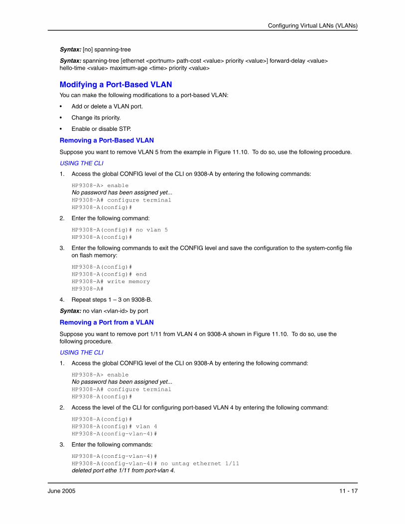
Configuring Virtual LANs (VLANs)
Syntax: [no] spanning-tree
Syntax: spanning-tree [ethernet <portnum> path-cost <value> priority <value>] forward-delay <value> hello-time <value> maximum-age <time> priority <value>
Modifying a Port-Based VLANYou can make the following modifications to a port-based VLAN:
• Add or delete a VLAN port.
• Change its priority.
• Enable or disable STP.
Removing a Port-Based VLAN
Suppose you want to remove VLAN 5 from the example in Figure 11.10. To do so, use the following procedure.
USING THE CLI
1. Access the global CONFIG level of the CLI on 9308-A by entering the following commands:
HP9308-A> enable No password has been assigned yet... HP9308-A# configure terminal HP9308-A(config)#
2. Enter the following command:
HP9308-A(config)# no vlan 5 HP9308-A(config)#
3. Enter the following commands to exit the CONFIG level and save the configuration to the system-config file on flash memory:
HP9308-A(config)# HP9308-A(config)# end HP9308-A# write memory HP9308-A#
4. Repeat steps 1 – 3 on 9308-B.
Syntax: no vlan <vlan-id> by port
Removing a Port from a VLAN
Suppose you want to remove port 1/11 from VLAN 4 on 9308-A shown in Figure 11.10. To do so, use the following procedure.
USING THE CLI
1. Access the global CONFIG level of the CLI on 9308-A by entering the following command:
HP9308-A> enable No password has been assigned yet... HP9308-A# configure terminal HP9308-A(config)#
2. Access the level of the CLI for configuring port-based VLAN 4 by entering the following command:
HP9308-A(config)# HP9308-A(config)# vlan 4 HP9308-A(config-vlan-4)#
3. Enter the following commands:
HP9308-A(config-vlan-4)# HP9308-A(config-vlan-4)# no untag ethernet 1/11 deleted port ethe 1/11 from port-vlan 4.
June 2005 11 - 17
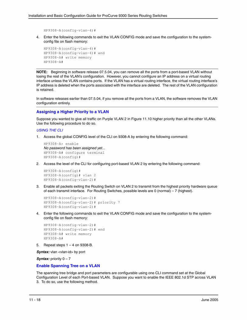
Installation and Basic Configuration Guide for ProCurve 9300 Series Routing Switches
HP9308-A(config-vlan-4)#
4. Enter the following commands to exit the VLAN CONFIG mode and save the configuration to the system-config file on flash memory:
HP9308-A(config-vlan-4)# HP9308-A(config-vlan-4)# end HP9308-A# write memory HP9308-A#
NOTE: Beginning in software release 07.5.04, you can remove all the ports from a port-based VLAN without losing the rest of the VLAN’s configuration. However, you cannot configure an IP address on a virtual routing interface unless the VLAN contains ports. If the VLAN has a virtual routing interface, the virtual routing interface’s IP address is deleted when the ports associated with the interface are deleted. The rest of the VLAN configuration is retained. In software releases earlier than 07.5.04, if you remove all the ports from a VLAN, the software removes the VLAN configuration entirely.
Assigning a Higher Priority to a VLAN
Suppose you wanted to give all traffic on Purple VLAN 2 in Figure 11.10 higher priority than all the other VLANs. Use the following procedure to do so.
USING THE CLI
1. Access the global CONFIG level of the CLI on 9308-A by entering the following command:
HP9308-A> enable No password has been assigned yet... HP9308-A# configure terminal HP9308-A(config)#
2. Access the level of the CLI for configuring port-based VLAN 2 by entering the following command:
HP9308-A(config)# HP9308-A(config)# vlan 2 HP9308-A(config-vlan-2)#
3. Enable all packets exiting the Routing Switch on VLAN 2 to transmit from the highest priority hardware queue of each transmit interface. For Routing Switches, possible levels are 0 (normal) – 7 (highest).
HP9308-A(config-vlan-2)# HP9308-A(config-vlan-2)# priority 7 HP9308-A(config-vlan-2)#
4. Enter the following commands to exit the VLAN CONFIG mode and save the configuration to the system-config file on flash memory:
HP9308-A(config-vlan-2)# HP9308-A(config-vlan-2)# end HP9308-A# write memory HP9308-A#
5. Repeat steps 1 – 4 on 9308-B.
Syntax: vlan <vlan-id> by port
Syntax: priority 0 – 7
Enable Spanning Tree on a VLAN
The spanning tree bridge and port parameters are configurable using one CLI command set at the Global Configuration Level of each Port-based VLAN. Suppose you want to enable the IEEE 802.1d STP across VLAN 3. To do so, use the following method.
11 - 18 June 2005
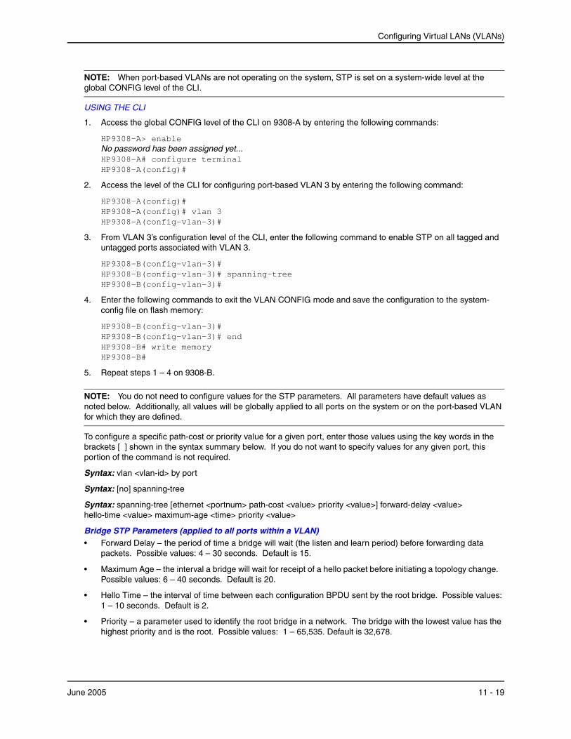
Configuring Virtual LANs (VLANs)
NOTE: When port-based VLANs are not operating on the system, STP is set on a system-wide level at the global CONFIG level of the CLI.
USING THE CLI
1. Access the global CONFIG level of the CLI on 9308-A by entering the following commands:
HP9308-A> enable No password has been assigned yet... HP9308-A# configure terminal HP9308-A(config)#
2. Access the level of the CLI for configuring port-based VLAN 3 by entering the following command:
HP9308-A(config)# HP9308-A(config)# vlan 3 HP9308-A(config-vlan-3)#
3. From VLAN 3’s configuration level of the CLI, enter the following command to enable STP on all tagged and untagged ports associated with VLAN 3.
HP9308-B(config-vlan-3)# HP9308-B(config-vlan-3)# spanning-tree HP9308-B(config-vlan-3)#
4. Enter the following commands to exit the VLAN CONFIG mode and save the configuration to the system-config file on flash memory:
HP9308-B(config-vlan-3)# HP9308-B(config-vlan-3)# end HP9308-B# write memory HP9308-B#
5. Repeat steps 1 – 4 on 9308-B.
NOTE: You do not need to configure values for the STP parameters. All parameters have default values as noted below. Additionally, all values will be globally applied to all ports on the system or on the port-based VLAN for which they are defined.
To configure a specific path-cost or priority value for a given port, enter those values using the key words in the brackets [ ] shown in the syntax summary below. If you do not want to specify values for any given port, this portion of the command is not required.
Syntax: vlan <vlan-id> by port
Syntax: [no] spanning-tree
Syntax: spanning-tree [ethernet <portnum> path-cost <value> priority <value>] forward-delay <value> hello-time <value> maximum-age <time> priority <value>
Bridge STP Parameters (applied to all ports within a VLAN)• Forward Delay – the period of time a bridge will wait (the listen and learn period) before forwarding data
packets. Possible values: 4 – 30 seconds. Default is 15.
• Maximum Age – the interval a bridge will wait for receipt of a hello packet before initiating a topology change. Possible values: 6 – 40 seconds. Default is 20.
• Hello Time – the interval of time between each configuration BPDU sent by the root bridge. Possible values: 1 – 10 seconds. Default is 2.
• Priority – a parameter used to identify the root bridge in a network. The bridge with the lowest value has the highest priority and is the root. Possible values: 1 – 65,535. Default is 32,678.
June 2005 11 - 19

Installation and Basic Configuration Guide for ProCurve 9300 Series Routing Switches
Port Parameters (applied to a specified port within a VLAN)• Path Cost – a parameter used to assign a higher or lower path cost to a port. Possible values: 1 – 65535.
Default is (1000/Port Speed) for Half-Duplex ports and is (1000/Port Speed)/2 for Full-Duplex ports.
• Priority – value determines when a port will be rerouted in relation to other ports. Possible values: 0 – 255. Default is 128.
Configuring IP Subnet, IPX Network and Protocol-Based VLANsProtocol-based VLANs provide the ability to define separate broadcast domains for several unique Layer 3 protocols within a single Layer 2 broadcast domain. Some applications for this feature might include security between departments with unique protocol requirements. This feature enables you to limit the amount of broadcast traffic end-stations, servers, and Routing Switches need to accept.
NOTE: See “Configuring AppleTalk Cable VLANs” on page 11-28 for information about configuring an AppleTalk cable VLAN.
Configuration ExampleSuppose you want to create five separate Layer 3 broadcast domains within a single Layer 2 STP broadcast domain:
• Three broadcast domains, one for each of three separate IP subnets
• One for IPX Network 1
• One for the Appletalk protocol
Also suppose you want a single router interface to be present within all of these separate broadcast domains, without using IEEE 802.1q VLAN tagging or any proprietary form of VLAN tagging.
Figure 11.11 shows this configuration.
Figure 11.11 Protocol-based (Layer 3) VLANs
Port 1/8IP sub-net 1
IPX network 1AppleTalk cable 100
IP sub-net 2
9304M
9308M
AppleTalk cable 100
IP sub-net 1
IP sub-net 2
IPX network 1
port 1/8
Ports 1/4 - 1/6, 1/8IP sub-net 2
Ports 1/1 - 1/6, 1/8IPX network 1
Ports 1/4 - 1/6, 1/8AppleTalkcable 100
Ports 1/1 - 1/3, 1/8IP sub-net 1
11 - 20 June 2005
Configuring Virtual LANs (VLANs)
To configure the VLANs shown in Figure 11.11, use the following procedure.
USING THE CLI
1. To permanently assign ports 1/1 – 1/8 and port 1/25 to IP subnet VLAN 1.1.1.0, enter the following commands:
HP9304> en No password has been assigned yet... HP9304# config t HP9304(config)# HP9304(config)# ip-subnet 1.1.1.0/24 name Green HP9304(config-ip-subnet)# no dynamic HP9304(config-ip-subnet)# static ethernet 1/1 to 1/8 ethernet 1/25
2. To permanently assign ports 1/9 – 1/16 and port 1/25 to IP subnet VLAN 1.1.2.0, enter the following commands:
HP9304(config-ip-subnet)# ip-subnet 1.1.2.0/24 name Yellow HP9304(config-ip-subnet)# no dynamic HP9304(config-ip-subnet)# static ethernet 1/9 to 1/16 ethernet 1/25
3. To permanently assign ports 1/17 – 1/25 to IP subnet VLAN 1.1.3.0, enter the following commands:
HP9304(config-ip-subnet)# ip-subnet 1.1.3.0/24 name Brown HP9304(config-ip-subnet)# no dynamic HP9304(config-ip-subnet)# static ethernet 1/17 to 1/25
4. To permanently assign ports 1/1 – 1/12 and port 1/25 to IPX network 1 VLAN, enter the following commands:
HP9304(config-ip-subnet)# ipx-network 1 ethernet_802.3 name Blue HP9304(config-ipx-network)# no dynamic HP9304(config-ipx-network)# static ethernet 1/1 to 1/12 ethernet 1/25 HP9304(config-ipx-network)#
5. To permanently assign ports 1/12 – 1/25 to Appletalk VLAN, enter the following commands:
HP9304(config-ipx-proto)# atalk-proto name Red HP9304(config-atalk-proto)# no dynamic HP9304(config-atalk-proto)# static ethernet 1/13 to 1/25 HP9304(config-atalk-proto)# end HP9304# write memory HP9304#
Syntax: ip-subnet <ip-addr> <ip-mask> [name <string>]
Syntax: ipx-network <ipx-network-number> <frame-encapsulation-type> netbios-allow | netbios-disallow [name <string>]
Syntax: ip-proto | ipx-proto | atalk-proto | decnet-proto | netbios-proto | other-proto static | exclude | dynamic ethernet <portnum> [to <portnum>] [name <string>]
Routing Between VLANs Using Virtual Routing InterfacesProCurve Routing Switches offer the ability to create a virtual routing interface within a Layer 2 STP port-based VLAN or within each Layer 3 protocol, IP subnet, or IPX network VLAN. This combination of multiple Layer 2 and/or Layer 3 broadcast domains and virtual routing interfaces are the basis for Hewlett-Packard’s very powerful Integrated Switch Routing (ISR) technology. ISR is very flexible and can solve many networking problems. The following example is meant to provide ideas by demonstrating some of the concepts of ISR.
Example: Suppose you want to move routing out to each of three buildings in a network. Remember that the only protocols present on VLAN 2 and VLAN 3 are IP and IPX. Therefore, you can eliminate tagged ports 25 and 26 from both VLAN 2 and VLAN 3 and create new tagged port-based VLANs to support separate IP subnets and IPX networks for each backbone link.
June 2005 11 - 21

Installation and Basic Configuration Guide for ProCurve 9300 Series Routing Switches
You also need to create unique IP subnets and IPX networks within VLAN 2 and VLAN 3 at each building. This will create a fully routed IP and IPX backbone for VLAN 2 and VLAN 3. However, VLAN 4 has no protocol restrictions across the backbone. In fact there are requirements for NetBIOS and DecNet to be bridged among the three building locations. The IP subnet and IPX network that exists within VLAN 4 must remain a flat Layer 2 switched STP domain. You enable routing for IP and IPX on a virtual routing interface only on HP9304-A. This will provide the flat IP and IPX segment with connectivity to the rest of the network. Within VLAN 4 IP and IPX will follow the STP topology. All other IP subnets and IPX networks will be fully routed and have use of all paths at all times during normal operation.
Figure 11.12 shows the configuration described above.
11 - 22 June 2005
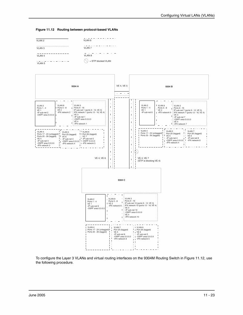
Configuring Virtual LANs (VLANs)
Figure 11.12 Routing between protocol-based VLANs
VLAN 8
= STP blocked VLAN
VLAN 7Port 26 (tagged)VE 6-IP sub-net 8-IPX network 8
VLAN 2Ports 1 - 4VE 1-IP sub-net 6
VLAN 8Ports 5 - 8VE 2-IPX network 6
VLAN 3Ports 9 - 16IP sub-net 7 (ports 9 - 12, VE 3)IPX network 7 (ports 13 - 16, VE 4)VE 3-IP sub-net 7-OSPF area 0.0.0.0VE 4-IPX network 7
VLAN 4Ports 17 - 24 (untagged)Ports 25 - 26 (tagged)
VLAN 5Port 25 (tagged)VE 5-IP sub-net 4-OSPF area 0.0.0.0-IPX network 4
VLAN 6Port 26 (tagged)VE 6-IP sub-net 5-OSPF area 0.0.0.0-IPX network 5
VLAN 2Ports 1 - 4VE 1-IP sub-net 9-OSPF area 0.0.0.0
VLAN 8Ports 5 - 8VE 2-IPX network 9
VLAN 3Ports 9 - 16IP sub-net 10 (ports 9 - 12, VE 3)IPX network 10 (ports 13 - 16, VE 4)VE 3-IP sub-net 10-OSPF area 0.0.0.0VE 4-IPX network 10
VLAN 4Ports 17 - 24 (untagged)Ports 25 - 26 (tagged)
VLAN 7Port 25 (tagged)VE 5-IP sub-net 8-OSPF area 0.0.0.0-IPX network 8
9304 B
VLAN 6Port 26 (tagged)VE 7-IP sub-net 5-OSPF 0.0.0.0-IPX network 5
VLAN 2Ports 1 - 4VE 1-IP sub-net 2-OSPF area 0.0.0.0
VLAN 8Ports 5 - 8VE 2-IPX network 2
VLAN 3Ports 9 - 16IP sub-net 1 (ports 9 - 12, VE 3)IPX network 1 (ports 13 - 16, VE 4)VE 3-IP sub-net 1-OSPF area 0.0.0.0VE 4-IPX network 1
VLAN 4Ports 17 - 24 (untagged)Ports 25 - 26 (tagged)VE 5-IP sub-net 3-OSPF area 0.0.0.0-IPX network 3
VLAN 5Port 25 (tagged)VE 6-IP sub-net 4-OSPF area 0.0.0.0-IPX network 4
VLAN 6
VLAN 7
VLAN 5
VE 4, VE 7(STP is blocking VE 4)
VLAN 2
VLAN 3
VLAN 4
VE 4, VE 5
VE 4, VE 6
9304 A
9304 C
To configure the Layer 3 VLANs and virtual routing interfaces on the 9304M Routing Switch in Figure 11.12, use the following procedure.
June 2005 11 - 23

Installation and Basic Configuration Guide for ProCurve 9300 Series Routing Switches
USING THE CLI
Configuring HP9304-A
Enter the following commands to configure HP9304-A. The following commands enable OSPF or RIP routing and IPX routing.
HP9304> en No password has been assigned yet... HP9304# configure terminal HP9304(config)# hostname HP9304-A HP9304-A(config)# router ospf HP9304-A(config-ospf-router)# area 0.0.0.0 normal HP9304-A(config-ospf-router)# router ipx ipx routing enabled for next power cycle. Please save configuration to flash and reboot. HP9304-A(config-ospf-router)#
The following commands create the port-based VLAN 2. In the previous example, an external 9304M defined the router interfaces for VLAN 2. With ISR, routing for VLAN 2 is done locally within each 9304M. Therefore, there are two ways you can solve this problem. One way is to create a unique IP subnet and IPX network VLAN, each with its own virtual routing interface and unique IP or IPX address within VLAN 2 on each 9304M. In this example, this is the configuration used for VLAN 3. The second way is to split VLAN 2 into two separate port-based VLANs and create a virtual router interface within each port-based VLAN. Later in this example, this second option is used to create a port-based VLAN 8 to show that there are multiple ways to accomplish the same task with ISR.
You also need to create the Other-Protocol VLAN within port-based VLAN 2 and 8 to prevent unwanted protocols from being Layer 2 switched within port-based VLAN 2 or 8. Note that the only port-based VLAN that requires STP in this example is VLAN 4. You will need to configure the rest of the network to prevent the need to run STP.
HP9304-A(config-ospf-router)# vlan 2 name IP-Subnet_1.1.2.0/24 HP9304-A(config-vlan-2)# untag e 1/1 to 1/4 HP9304-A(config-vlan-2)# no spanning-tree HP9304-A(config-vlan-2)# router-interface ve1 HP9304-A(config-vlan-2)# other-proto name block_other_protocols HP9304-A(config-vlan-other-proto)# no dynamic HP9304-A(config-vlan-other-proto)# exclude e 1/1 to 1/4
Once you have defined the port-based VLAN and created the virtual routing interface, you need to configure the virtual routing interface just as you would configure a physical interface.
HP9304-A(config-vlan-other-proto)# interface ve1 HP9304-A(config-vif-1)# ip address 1.1.2.1/24 HP9304-A(config-vif-1)# ip ospf area 0.0.0.0
Do the same thing for VLAN 8.
HP9304-A(config-vif-1)# vlan 8 name IPX_Network2 HP9304-A(config-vlan-8)# untag ethernet 1/5 to 1/8 HP9304-A(config-vlan-8)# no spanning-tree HP9304-A(config-vlan-8)# router-interface ve 2 HP9304-A(config-vlan-8)# other-proto name block-other-protocols HP9304-A(config-vlan-other-proto)# no dynamic HP9304-A(config-vlan-other-proto)# exclude ethernet 1/5 to 1/8 HP9304-A(config-vlan-other-proto)# int ve2 HP9304-A(config-vif-2)# ipx network 2 ethernet_802.3 HP9304-A(config-vif-2)#
The next thing you need to do is create VLAN 3. This is very similar to the previous example with the addition of virtual routing interfaces to the IP subnet and IPX network VLANs. Also there is no need to exclude ports from the IP subnet and IPX network VLANs on the Routing Switch.
HP9304-A(config-vif-2)# vlan 3 name IP_Sub_&_IPX_Net_VLAN HP9304-A(config-vlan-3)# untag e 1/9 to 1/16
11 - 24 June 2005
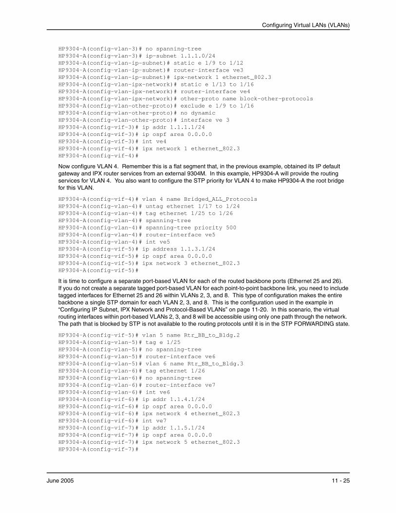
Configuring Virtual LANs (VLANs)
HP9304-A(config-vlan-3)# no spanning-tree HP9304-A(config-vlan-3)# ip-subnet 1.1.1.0/24 HP9304-A(config-vlan-ip-subnet)# static e 1/9 to 1/12 HP9304-A(config-vlan-ip-subnet)# router-interface ve3 HP9304-A(config-vlan-ip-subnet)# ipx-network 1 ethernet_802.3 HP9304-A(config-vlan-ipx-network)# static e 1/13 to 1/16 HP9304-A(config-vlan-ipx-network)# router-interface ve4 HP9304-A(config-vlan-ipx-network)# other-proto name block-other-protocols HP9304-A(config-vlan-other-proto)# exclude e 1/9 to 1/16 HP9304-A(config-vlan-other-proto)# no dynamic HP9304-A(config-vlan-other-proto)# interface ve 3 HP9304-A(config-vif-3)# ip addr 1.1.1.1/24 HP9304-A(config-vif-3)# ip ospf area 0.0.0.0 HP9304-A(config-vif-3)# int ve4 HP9304-A(config-vif-4)# ipx network 1 ethernet_802.3 HP9304-A(config-vif-4)#
Now configure VLAN 4. Remember this is a flat segment that, in the previous example, obtained its IP default gateway and IPX router services from an external 9304M. In this example, HP9304-A will provide the routing services for VLAN 4. You also want to configure the STP priority for VLAN 4 to make HP9304-A the root bridge for this VLAN.
HP9304-A(config-vif-4)# vlan 4 name Bridged_ALL_Protocols HP9304-A(config-vlan-4)# untag ethernet 1/17 to 1/24 HP9304-A(config-vlan-4)# tag ethernet 1/25 to 1/26 HP9304-A(config-vlan-4)# spanning-tree HP9304-A(config-vlan-4)# spanning-tree priority 500 HP9304-A(config-vlan-4)# router-interface ve5 HP9304-A(config-vlan-4)# int ve5 HP9304-A(config-vif-5)# ip address 1.1.3.1/24 HP9304-A(config-vif-5)# ip ospf area 0.0.0.0 HP9304-A(config-vif-5)# ipx network 3 ethernet_802.3 HP9304-A(config-vif-5)#
It is time to configure a separate port-based VLAN for each of the routed backbone ports (Ethernet 25 and 26). If you do not create a separate tagged port-based VLAN for each point-to-point backbone link, you need to include tagged interfaces for Ethernet 25 and 26 within VLANs 2, 3, and 8. This type of configuration makes the entire backbone a single STP domain for each VLAN 2, 3, and 8. This is the configuration used in the example in “Configuring IP Subnet, IPX Network and Protocol-Based VLANs” on page 11-20. In this scenario, the virtual routing interfaces within port-based VLANs 2, 3, and 8 will be accessible using only one path through the network. The path that is blocked by STP is not available to the routing protocols until it is in the STP FORWARDING state.
HP9304-A(config-vif-5)# vlan 5 name Rtr_BB_to_Bldg.2 HP9304-A(config-vlan-5)# tag e 1/25 HP9304-A(config-vlan-5)# no spanning-tree HP9304-A(config-vlan-5)# router-interface ve6 HP9304-A(config-vlan-5)# vlan 6 name Rtr_BB_to_Bldg.3 HP9304-A(config-vlan-6)# tag ethernet 1/26 HP9304-A(config-vlan-6)# no spanning-tree HP9304-A(config-vlan-6)# router-interface ve7 HP9304-A(config-vlan-6)# int ve6 HP9304-A(config-vif-6)# ip addr 1.1.4.1/24 HP9304-A(config-vif-6)# ip ospf area 0.0.0.0 HP9304-A(config-vif-6)# ipx network 4 ethernet_802.3 HP9304-A(config-vif-6)# int ve7 HP9304-A(config-vif-7)# ip addr 1.1.5.1/24 HP9304-A(config-vif-7)# ip ospf area 0.0.0.0 HP9304-A(config-vif-7)# ipx network 5 ethernet_802.3 HP9304-A(config-vif-7)#
June 2005 11 - 25
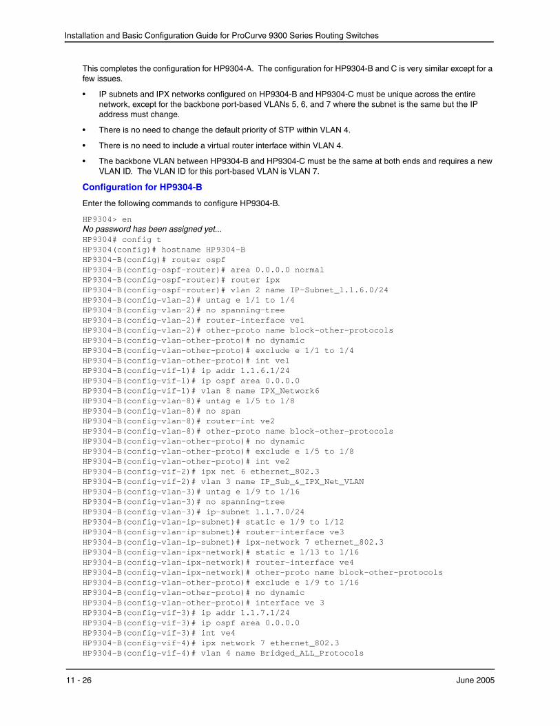
Installation and Basic Configuration Guide for ProCurve 9300 Series Routing Switches
This completes the configuration for HP9304-A. The configuration for HP9304-B and C is very similar except for a few issues.
• IP subnets and IPX networks configured on HP9304-B and HP9304-C must be unique across the entire network, except for the backbone port-based VLANs 5, 6, and 7 where the subnet is the same but the IP address must change.
• There is no need to change the default priority of STP within VLAN 4.
• There is no need to include a virtual router interface within VLAN 4.
• The backbone VLAN between HP9304-B and HP9304-C must be the same at both ends and requires a new VLAN ID. The VLAN ID for this port-based VLAN is VLAN 7.
Configuration for HP9304-B
Enter the following commands to configure HP9304-B.
HP9304> en No password has been assigned yet... HP9304# config t HP9304(config)# hostname HP9304-B HP9304-B(config)# router ospf HP9304-B(config-ospf-router)# area 0.0.0.0 normal HP9304-B(config-ospf-router)# router ipx HP9304-B(config-ospf-router)# vlan 2 name IP-Subnet_1.1.6.0/24 HP9304-B(config-vlan-2)# untag e 1/1 to 1/4 HP9304-B(config-vlan-2)# no spanning-tree HP9304-B(config-vlan-2)# router-interface ve1 HP9304-B(config-vlan-2)# other-proto name block-other-protocols HP9304-B(config-vlan-other-proto)# no dynamic HP9304-B(config-vlan-other-proto)# exclude e 1/1 to 1/4 HP9304-B(config-vlan-other-proto)# int ve1 HP9304-B(config-vif-1)# ip addr 1.1.6.1/24 HP9304-B(config-vif-1)# ip ospf area 0.0.0.0 HP9304-B(config-vif-1)# vlan 8 name IPX_Network6 HP9304-B(config-vlan-8)# untag e 1/5 to 1/8 HP9304-B(config-vlan-8)# no span HP9304-B(config-vlan-8)# router-int ve2 HP9304-B(config-vlan-8)# other-proto name block-other-protocols HP9304-B(config-vlan-other-proto)# no dynamic HP9304-B(config-vlan-other-proto)# exclude e 1/5 to 1/8 HP9304-B(config-vlan-other-proto)# int ve2 HP9304-B(config-vif-2)# ipx net 6 ethernet_802.3 HP9304-B(config-vif-2)# vlan 3 name IP_Sub_&_IPX_Net_VLAN HP9304-B(config-vlan-3)# untag e 1/9 to 1/16 HP9304-B(config-vlan-3)# no spanning-tree HP9304-B(config-vlan-3)# ip-subnet 1.1.7.0/24 HP9304-B(config-vlan-ip-subnet)# static e 1/9 to 1/12 HP9304-B(config-vlan-ip-subnet)# router-interface ve3 HP9304-B(config-vlan-ip-subnet)# ipx-network 7 ethernet_802.3 HP9304-B(config-vlan-ipx-network)# static e 1/13 to 1/16 HP9304-B(config-vlan-ipx-network)# router-interface ve4 HP9304-B(config-vlan-ipx-network)# other-proto name block-other-protocols HP9304-B(config-vlan-other-proto)# exclude e 1/9 to 1/16 HP9304-B(config-vlan-other-proto)# no dynamic HP9304-B(config-vlan-other-proto)# interface ve 3 HP9304-B(config-vif-3)# ip addr 1.1.7.1/24 HP9304-B(config-vif-3)# ip ospf area 0.0.0.0 HP9304-B(config-vif-3)# int ve4 HP9304-B(config-vif-4)# ipx network 7 ethernet_802.3 HP9304-B(config-vif-4)# vlan 4 name Bridged_ALL_Protocols
11 - 26 June 2005
Configuring Virtual LANs (VLANs)
HP9304-B(config-vlan-4)# untag ethernet 1/17 to 1/24 HP9304-B(config-vlan-4)# tag ethernet 1/25 to 1/26 HP9304-B(config-vlan-4)# spanning-tree HP9304-B(config-vlan-4)# vlan 5 name Rtr_BB_to_Bldg.1 HP9304-B(config-vlan-5)# tag e 1/25 HP9304-B(config-vlan-5)# no spanning-tree HP9304-B(config-vlan-5)# router-interface ve5 HP9304-B(config-vlan-5)# vlan 7 name Rtr_BB_to_Bldg.3 HP9304-B(config-vlan-7)# tag ethernet 1/26 HP9304-B(config-vlan-7)# no spanning-tree HP9304-B(config-vlan-7)# router-interface ve6 HP9304-B(config-vlan-7)# int ve5 HP9304-B(config-vif-5)# ip addr 1.1.4.2/24 HP9304-B(config-vif-5)# ip ospf area 0.0.0.0 HP9304-B(config-vif-5)# ipx network 4 ethernet_802.3 HP9304-B(config-vif-5)# int ve6 HP9304-B(config-vif-6)# ip addr 1.1.8.1/24 HP9304-B(config-vif-6)# ip ospf area 0.0.0.0 HP9304-B(config-vif-6)# ipx network 8 ethernet_802.3 HP9304-B(config-vif-6)#
Configuration for HP9304-C
Enter the following commands to configure HP9304-C.
HP9304> en No password has been assigned yet... HP9304# config t HP9304(config)# hostname HP9304-C HP9304-C(config)# router ospf HP9304-C(config-ospf-router)# area 0.0.0.0 normal HP9304-C(config-ospf-router)# router ipx HP9304-C(config-ospf-router)# vlan 2 name IP-Subnet_1.1.9.0/24 HP9304-C(config-vlan-2)# untag e 1/1 to 1/4 HP9304-C(config-vlan-2)# no spanning-tree HP9304-C(config-vlan-2)# router-interface ve1 HP9304-C(config-vlan-2)# other-proto name block-other-protocols HP9304-C(config-vlan-other-proto)# no dynamic HP9304-C(config-vlan-other-proto)# exclude e 1/1 to 1/4 HP9304-C(config-vlan-other-proto)# int ve1 HP9304-C(config-vif-1)# ip addr 1.1.9.1/24 HP9304-C(config-vif-1)# ip ospf area 0.0.0.0 HP9304-C(config-vif-1)# vlan 8 name IPX_Network9 HP9304-C(config-vlan-8)# untag e 1/5 to 1/8 HP9304-C(config-vlan-8)# no span HP9304-C(config-vlan-8)# router-int ve2 HP9304-C(config-vlan-8)# other-proto name block-other-protocols HP9304-C(config-vlan-other-proto)# no dynamic HP9304-C(config-vlan-other-proto)# exclude e 1/5 to 1/8 HP9304-C(config-vlan-other-proto)# int ve2 HP9304-C(config-vif-2)# ipx net 9 ethernet_802.3 HP9304-C(config-vif-2)# vlan 3 name IP_Sub_&_IPX_Net_VLAN HP9304-C(config-vlan-3)# untag e 1/9 to 1/16 HP9304-C(config-vlan-3)# no spanning-tree HP9304-C(config-vlan-3)# ip-subnet 1.1.10.0/24 HP9304-C(config-vlan-ip-subnet)# static e 1/9 to 1/12 HP9304-C(config-vlan-ip-subnet)# router-interface ve3 HP9304-C(config-vlan-ip-subnet)# ipx-network 10 ethernet_802.3 HP9304-C(config-vlan-ipx-network)# static e 1/13 to 1/16 HP9304-C(config-vlan-ipx-network)# router-interface ve4
June 2005 11 - 27

Installation and Basic Configuration Guide for ProCurve 9300 Series Routing Switches
HP9304-C(config-vlan-ipx-network)# other-proto name block-other-protocols HP9304-C(config-vlan-other-proto)# exclude e 1/9 to 1/16 HP9304-C(config-vlan-other-proto)# no dynamic HP9304-C(config-vlan-other-proto)# interface ve 3 HP9304-C(config-vif-3)# ip addr 1.1.10.1/24 HP9304-C(config-vif-3)# ip ospf area 0.0.0.0 HP9304-C(config-vif-3)# int ve4 HP9304-C(config-vif-4)# ipx network 10 ethernet_802.3 HP9304-C(config-vif-4)# vlan 4 name Bridged_ALL_Protocols HP9304-C(config-vlan-4)# untag ethernet 1/17 to 1/24 HP9304-C(config-vlan-4)# tag ethernet 1/25 to 1/26 HP9304-C(config-vlan-4)# spanning-tree HP9304-C(config-vlan-4)# vlan 7 name Rtr_BB_to_Bldg.2 HP9304-C(config-vlan-7)# tag e 1/25 HP9304-C(config-vlan-7)# no spanning-tree HP9304-C(config-vlan-7)# router-interface ve5 HP9304-C(config-vlan-7)# vlan 6 name Rtr_BB_to_Bldg.1 HP9304-C(config-vlan-6)# tag ethernet 1/26 HP9304-C(config-vlan-6)# no spanning-tree HP9304-C(config-vlan-6)# router-interface ve6 HP9304-C(config-vlan-6)# int ve5 HP9304-C(config-vif-5)# ip addr 1.1.8.2/24 HP9304-C(config-vif-5)# ip ospf area 0.0.0.0 HP9304-C(config-vif-5)# ipx network 8 ethernet_802.3 HP9304-C(config-vif-5)# int ve6 HP9304-C(config-vif-6)# ip addr 1.1.5.2/24 HP9304-C(config-vif-6)# ip ospf area 0.0.0.0 HP9304-C(config-vif-6)# ipx network 5 ethernet_802.3 HP9304-C(config-vif-6)#
Configuring AppleTalk Cable VLANsYou can configure up to eight AppleTalk cable VLANs within a port-based VLAN.
To configure an AppleTalk cable VLAN, you create a port-based VLAN, then create up to eight cable VLANs within the port-based VLAN. You create the AppleTalk cable VLAN by assigning a number to the VLAN, optionally naming the cable VLAN, assigning ports from the port-based VLAN, and specifying the router interface (virtual routing interface) on which the Routing Switch will send and receive traffic for the cable VLAN.
All the ports in an AppleTalk cable VLAN are within the same AppleTalk cable range. The device switches traffic within the VLAN and routes traffic between VLANs.
Configuration GuidelinesUse the following guidelines when configuring AppleTalk cable VLANs:
• Up to eight AppleTalk cable VLANs are supported in a protocol-based VLAN. Each VLAN must be numbered from 1 – 8.
• Each AppleTalk cable VLAN can have only one router interface. The router interface must be a virtual routing interface.
• The AppleTalk cable VLANs cannot overlap. Thus, you cannot use the same port in more than one AppleTalk cable VLAN.
• You must add the ports to the AppleTalk cable VLAN using the static option. You cannot use the dynamic or exclude options.
• You cannot have an AppleTalk cable VLAN and an AppleTalk protocol VLAN in the same port-based VLAN. If you already have an AppleTalk protocol VLAN in the port-based VLAN, you must delete the AppleTalk protocol VLAN first, then configure the AppleTalk cable VLAN.
11 - 28 June 2005
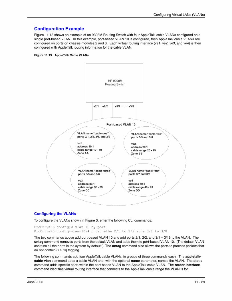
Configuring Virtual LANs (VLANs)
Configuration ExampleFigure 11.13 shows an example of an 9308M Routing Switch with four AppleTalk cable VLANs configured on a single port-based VLAN. In this example, port-based VLAN 10 is configured, then AppleTalk cable VLANs are configured on ports on chassis modules 2 and 3. Each virtual routing interface (ve1, ve2, ve3, and ve4) is then configured with AppleTalk routing information for the cable VLAN.
Figure 11.13 AppleTalk Cable VLANs
e3/1 e3/8. . .e2/1 e2/2
Port-based VLAN 10
VLAN name “cable-four”ports 3/7 and 3/8
ve4address 40.1cable range 40 - 49Zone DD
VLAN name “cable-one”ports 2/1, 2/2, 3/1, and 3/2
ve1address 10.1cable range 10 - 19Zone AA
VLAN name “cable-two”ports 3/3 and 3/4
ve2address 20.1cable range 20 - 29Zone BB
VLAN name “cable-three”ports 3/5 and 3/6
ve3address 30.1cable range 30 - 39Zone CC
HP 9308MRouting Switch
Configuring the VLANs
To configure the VLANs shown in Figure 3, enter the following CLI commands:
ProCurveRS(config)# vlan 10 by port ProCurveRS(config-vlan-10)# untag ethe 2/1 to 2/2 ethe 3/1 to 3/8
The two commands above add port-based VLAN 10 and add ports 2/1, 2/2, and 3/1 – 3/16 to the VLAN. The untag command removes ports from the default VLAN and adds them to port-based VLAN 10. (The default VLAN contains all the ports in the system by default.) The untag command also allows the ports to process packets that do not contain 802.1q tagging.
The following commands add four AppleTalk cable VLANs, in groups of three commands each. The appletalk-cable-vlan command adds a cable VLAN and, with the optional name parameter, names the VLAN. The static command adds specific ports within the port-based VLAN to the AppleTalk cable VLAN. The router-interface command identifies virtual routing interface that connects to the AppleTalk cable range the VLAN is for.
June 2005 11 - 29
Installation and Basic Configuration Guide for ProCurve 9300 Series Routing Switches
ProCurveRS(config-vlan-10)# appletalk-cable-vlan 1 name cable-one ProCurveRS(config-vlan-10)# static ethe 2/1 to 2/2 ethe 3/1 to 3/2 ProCurveRS(config-vlan-10)# router-interface ve 1 ProCurveRS(config-vlan-10)# appletalk-cable-vlan 2 name cable-two ProCurveRS(config-vlan-10)# static ethe 3/3 to 3/4 ProCurveRS(config-vlan-10)# router-interface ve 2 ProCurveRS(config-vlan-10)# appletalk-cable-vlan 3 name cable-three ProCurveRS(config-vlan-10)# static ethe 3/5 to 3/6 ProCurveRS(config-vlan-10)# router-interface ve 3 ProCurveRS(config-vlan-10)# appletalk-cable-vlan 4 name cable-four ProCurveRS(config-vlan-10)# static ethe 3/7 to 3/8 ProCurveRS(config-vlan-10)# router-interface ve 4
Syntax: appletalk-cable-vlan <vlan-id> [name <string>]
The <vlan-id> can be from 1 – 8.
The name <string> parameter specifies a name and can be a string up to 32 characters long.
Configuring the Router Interfaces
The following commands configure the router interfaces (virtual routing interfaces) associated with the AppleTalk cable VLANs. The interface ve commands add the virtual routing interfaces to the system. (The router-interface commands above refer to these interfaces but do not add them. You must add the interfaces using the interface ve command.)
For each virtual routing interface, additional commands configure the AppleTalk routing parameters for the interface. Notice that each virtual routing interface has a separate set of routing parameters. The routing parameters on each virtual routing interface are independent of the routing parameters on other virtual routing interfaces. Since each AppleTalk cable VLAN is associated with a separate virtual routing interface, each AppleTalk cable VLAN has a distinct set of routing parameters, separate from the routing parameters on other AppleTalk VLANs. In effect, each virtual routing interface contains a separate AppleTalk Routing Switch.
The appletalk address command configures the AppleTalk interface address on the virtual routing interface. The appletalk cable-range command specifies the cable range for the network. The appletalk routing command enables AppleTalk routing on the virtual routing interface. The zone-name commands add zones to the network. For information about the AppleTalk routing commands, see the “Configuring AppleTalk” chapter in the Advanced Configuration and Management Guide for ProCurve 9300/9400 Series Routing Switches.
The write memory command at the end of the example saves the configuration to the startup-config file.
ProCurveRS(config-vlan-10)# interface ve 1 ProCurveRS(config-vif-1)# appletalk cable-range 10 - 19 ProCurveRS(config-vif-1)# appletalk address 10.1 ProCurveRS(config-vif-1)# appletalk zone-name AA ProCurveRS(config-vif-1)# appletalk routing ProCurveRS(config-vif-1)# interface ve 2 ProCurveRS(config-vif-2)# appletalk cable-range 20 - 29 ProCurveRS(config-vif-2)# appletalk address 20.1 ProCurveRS(config-vif-2)# appletalk zone-name BB ProCurveRS(config-vif-2)# appletalk routing ProCurveRS(config-vif-2)# interface ve 3 ProCurveRS(config-vif-3)# appletalk cable-range 30 - 39 ProCurveRS(config-vif-3)# appletalk address 30.1 ProCurveRS(config-vif-3)# appletalk zone-name CC ProCurveRS(config-vif-3)# appletalk routing ProCurveRS(config-vif-3)# interface ve 4 ProCurveRS(config-vif-4)# appletalk cable-range 40 - 49 ProCurveRS(config-vif-4)# appletalk address 40.1 ProCurveRS(config-vif-4)# appletalk zone-name DD ProCurveRS(config-vif-4)# appletalk routing ProCurveRS(config-vif-4)# write memory
11 - 30 June 2005
Configuring Virtual LANs (VLANs)
Configuring Protocol VLANs With Dynamic PortsThe configuration examples for protocol VLANs in the sections above show how to configure the VLANs using static ports. You also can configure the following types of protocol VLANs with dynamic ports:
• AppleTalk protocol
• IP protocol
• IPX protocol
• IP subnet
• IPX network
NOTE: The software does not support dynamically adding ports to AppleTalk cable VLANs. Conceptually, an AppleTalk cable VLAN consists of a single network cable, connected to a single port. Therefore, dynamic addition and removal of ports is not applicable.
NOTE: You cannot route to or from protocol VLANs with dynamically added ports.
Aging of Dynamic PortsWhen you add the ports to the VLAN, the software automatically adds them all to the VLAN. However, dynamically added ports age out. If the age time for a dynamic port expires, the software removes the port from the VLAN. If that port receives traffic for the IP subnet or IPX network, the software adds the port to the VLAN again and starts the aging timer over. Each time the port receives traffic for the VLAN's IP subnet or IPX network, the aging timer starts over.
Dynamic ports within any protocol VLAN age out after 10 minutes, if no member protocol traffic is received on a port within the VLAN. The aged out port, however, remains as a candidate dynamic port for that VLAN. The port becomes active in the VLAN again if member protocol traffic is received on that port.
Once a port is re-activated, the aging out period for the port is reset to 20 minutes. Each time a member protocol packet is received by a candidate dynamic port (aged out port) the port becomes active again and the aging out period is reset for 20 minutes.
Configuration Guidelines• You cannot dynamically add a port to a protocol VLAN if the port has any routing configuration parameters.
For example, the port cannot have a virtual routing interface, IP subnet address, IPX network address, or AppleTalk network address configured on it.
• Once you dynamically add a port to a protocol VLAN, you cannot configure routing parameters on the port.
• Dynamic VLAN ports are not required or supported on AppleTalk cable VLANs.
Configuring an IP, IPX, or AppleTalk Protocol VLAN with Dynamic PortsTo configure an IP, IPX, or AppleTalk protocol VLAN with dynamic ports, use one of the following methods.
USING THE CLI
To configure port-based VLAN 10, then configure an IP protocol VLAN within the port-based VLAN with dynamic ports, enter the following commands such as the following:
ProCurveRS(config)# vlan 10 by port ProCurveRS(config-vlan-10)# untag ethernet 1/1 to 1/6 added untagged port ethe 1/1 to 1/6 to port-vlan 30. ProCurveRS(config-vlan-10)# ip-proto name IP_Prot_VLAN ProCurveRS(config-vlan-10)# dynamic ProCurveRS(config)# write memory
Syntax: vlan <vlan-id> by port [name <string>]
June 2005 11 - 31
Installation and Basic Configuration Guide for ProCurve 9300 Series Routing Switches
Syntax: untagged ethernet <portnum> to <portnum>
Or
Syntax: untagged ethernet <portnum> ethernet <portnum>
NOTE: Use the first untagged command for adding a range of ports. Use the second command for adding separate ports (not in a range).
Syntax: ip-proto [name <string>]
Syntax: ipx-proto [name <string>]
Syntax: appletalk-cable-vlan <num> [name <string>]
Syntax: dynamic
The procedure is similar for IPX and AppleTalk protocol VLANs. Enter ipx-proto or atalk-proto instead of ip-proto.
Configuring an IP Subnet VLAN with Dynamic PortsTo configure an IP subnet VLAN with dynamic ports, use one of the following methods.
USING THE CLI
To configure port-based VLAN 10, then configure an IP subnet VLAN within the port-based VLAN with dynamic ports, enter commands such as the following:
ProCurveRS(config)# vlan 10 by port name IP_VLAN ProCurveRS(config-vlan-10)# untag ethernet 1/1 to 1/6 added untagged port ethe 1/1 to 1/6 to port-vlan 10. ProCurveRS(config-vlan-10)# ip-subnet 1.1.1.0/24 name Mktg-LAN ProCurveRS(config-vlan-10)# dynamic ProCurveRS(config)# write memory
These commands create a port-based VLAN on chassis ports 1/1 – 1/6 named “Mktg-LAN”, configure an IP subnet VLAN within the port-based VLAN, and then add ports from the port-based VLAN dynamically.
Syntax: vlan <vlan-id> by port [name <string>]
Syntax: untagged ethernet <portnum> to <portnum>
Or
Syntax: untagged ethernet <portnum> ethernet <portnum>
NOTE: Use the first untagged command for adding a range of ports. Use the second command for adding separate ports (not in a range).
Syntax: ip-subnet <ip-addr> <ip-mask> [name <string>]
Or
Syntax: ip-subnet <ip-addr>/<mask-bits> [name <string>]
Syntax: dynamic
Configuring an IPX Network VLAN with Dynamic PortsTo configure an IPX network VLAN with dynamic ports, use one of the following methods.
USING THE CLI
To configure port-based VLAN 20, then configure an IPX network VLAN within the port-based VLAN with dynamic ports, enter commands such as the following:
ProCurveRS(config)# vlan 20 by port name IPX_VLAN
11 - 32 June 2005
Configuring Virtual LANs (VLANs)
ProCurveRS(config-vlan-10)# untag ethernet 2/1 to 2/6 added untagged port ethe 2/1 to 2/6 to port-vlan 20. ProCurveRS(config-vlan-10)# ipx-network abcd ethernet_ii name Eng-LAN ProCurveRS(config-vlan-10)# dynamic ProCurveRS(config)# write memory
These commands create a port-based VLAN on chassis ports 2/1 – 2/6 named “Eng-LAN”, configure an IPX network VLAN within the port-based VLAN, and then add ports from the port-based VLAN dynamically.
Syntax: vlan <vlan-id> by port [name <string>]
Syntax: untagged ethernet <portnum> to <portnum>
Or
Syntax: untagged ethernet <portnum> ethernet <portnum>
NOTE: Use the first untagged command for adding a range of ports. Use the second command for adding separate ports (not in a range).
Syntax: ipx-network <network-addr> ethernet_ii | ethernet_802.2 | ethernet_802.3 | ethernet_snap [name <string>]
Syntax: dynamic
Configuring Uplink Ports Within a Port-Based VLANYou can configure a subset of the ports in a port-based VLAN as uplink ports. When you configure uplink ports in a port-based VLAN, the device sends all broadcast and unknown-unicast traffic from a port in the VLAN to the uplink ports, but not to other ports within the VLAN. Thus, the uplink ports provide tighter broadcast control within the VLAN.
For example, if two ports within a port-based VLAN are Gigabit ports attached to the network and the other ports in the VLAN are 10/100 ports attached to clients, you can configure the two ports attached to the network as uplink ports. In this configuration, broadcast and unknown-unicast traffic in the VLAN does not go to all ports in the VLAN. The traffic goes only to the uplink ports. The clients on the network do not receive broadcast and unknown-unicast traffic from other ports, including other clients.
To configure uplink ports in a port-based VLAN, use the following CLI method.
USING THE CLI
To configure a port-based VLAN containing uplink ports, enter commands such as the following:
ProCurveRS(config)# vlan 10 by port ProCurveRS(config-vlan-10)# untag ethernet 1/1 to 1/24 ProCurveRS(config-vlan-10)# untag ethernet 2/1 to 2/2 ProCurveRS(config-vlan-10)# uplink-switch ethernet 2/1 to 2/2
Syntax: [no] uplink-switch ethernet <portnum> [to <portnum> | ethernet <portnum>]
In this example, 24 ports on a 10/100 module and two Gigabit ports on a Gigabit module are added to port-based VLAN 10. The two Gigabit ports are then configured as uplink ports.
USING THE WEB MANAGEMENT INTERFACE
You cannot configure uplink ports in a port-based VLAN using the Web management interface.
Configuring the Same IP Subnet Address on Multiple Port-Based VLANs
For an HP device to route between port-based VLANs, you must add a virtual routing interface to each VLAN. Generally, you also configure a unique IP subnet address on each virtual routing interface. For example, if you have three port-based VLANs, you add a virtual routing interface to each VLAN, then add a separate IP subnet
June 2005 11 - 33
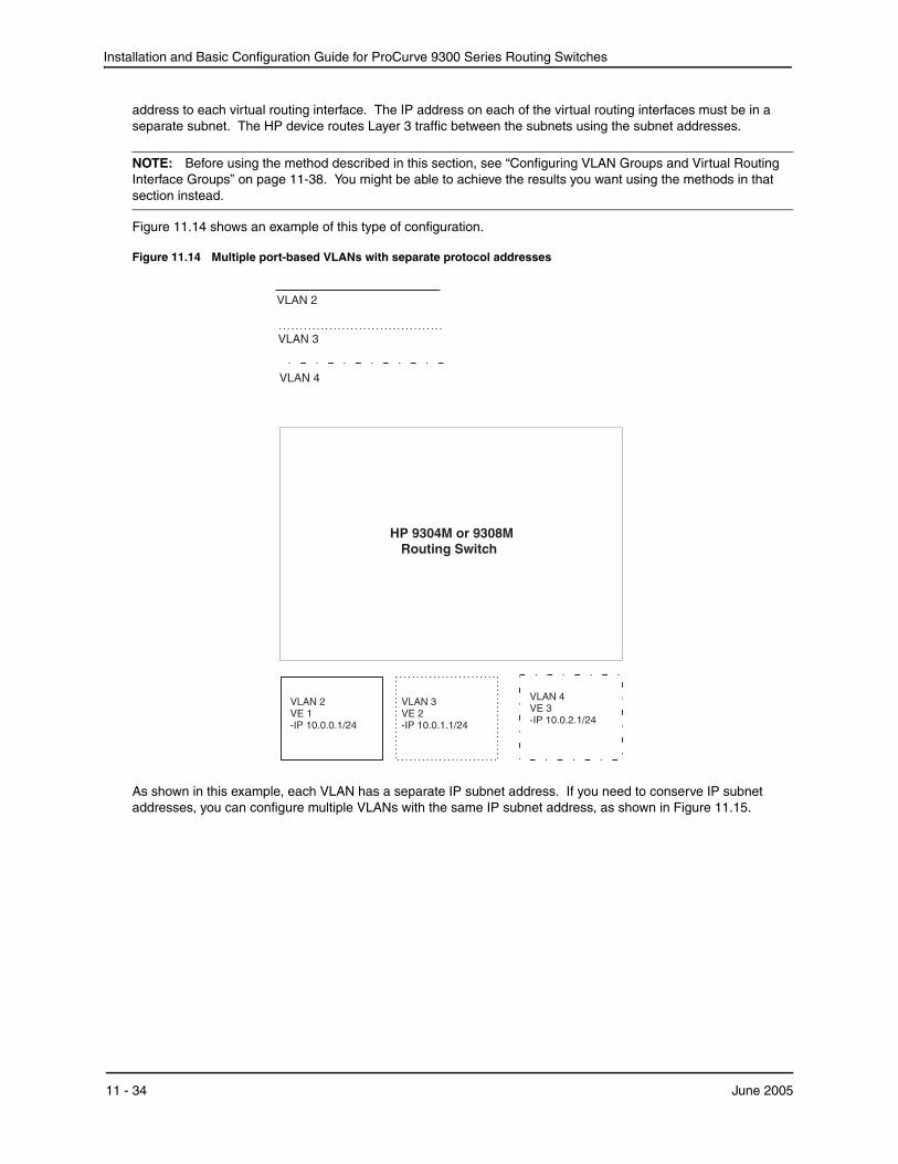
Installation and Basic Configuration Guide for ProCurve 9300 Series Routing Switches
address to each virtual routing interface. The IP address on each of the virtual routing interfaces must be in a separate subnet. The HP device routes Layer 3 traffic between the subnets using the subnet addresses.
NOTE: Before using the method described in this section, see “Configuring VLAN Groups and Virtual Routing Interface Groups” on page 11-38. You might be able to achieve the results you want using the methods in that section instead.
Figure 11.14 shows an example of this type of configuration.
Figure 11.14 Multiple port-based VLANs with separate protocol addresses
VLAN 2VE 1-IP 10.0.0.1/24
VLAN 4VE 3-IP 10.0.2.1/24
VLAN 2
VLAN 3
VLAN 4
VLAN 3VE 2-IP 10.0.1.1/24
HP 9304M or 9308MRouting Switch
As shown in this example, each VLAN has a separate IP subnet address. If you need to conserve IP subnet addresses, you can configure multiple VLANs with the same IP subnet address, as shown in Figure 11.15.
11 - 34 June 2005
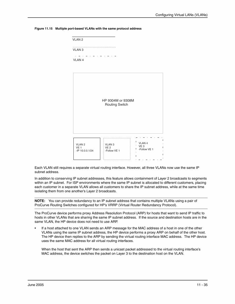
Configuring Virtual LANs (VLANs)
Figure 11.15 Multiple port-based VLANs with the same protocol address
HP 9304M or 9308MRouting Switch
VLAN 2VE 1-IP 10.0.0.1/24
VLAN 4VE 3-Follow VE 1
VLAN 2
VLAN 3
VLAN 4
VLAN 3VE 2-Follow VE 1
Each VLAN still requires a separate virtual routing interface. However, all three VLANs now use the same IP subnet address.
In addition to conserving IP subnet addresses, this feature allows containment of Layer 2 broadcasts to segments within an IP subnet. For ISP environments where the same IP subnet is allocated to different customers, placing each customer in a separate VLAN allows all customers to share the IP subnet address, while at the same time isolating them from one another’s Layer 2 broadcasts.
NOTE: You can provide redundancy to an IP subnet address that contains multiple VLANs using a pair of ProCurve Routing Switches configured for HP’s VRRP (Virtual Router Redundancy Protocol).
The ProCurve device performs proxy Address Resolution Protocol (ARP) for hosts that want to send IP traffic to hosts in other VLANs that are sharing the same IP subnet address. If the source and destination hosts are in the same VLAN, the HP device does not need to use ARP.
• If a host attached to one VLAN sends an ARP message for the MAC address of a host in one of the other VLANs using the same IP subnet address, the HP device performs a proxy ARP on behalf of the other host. The HP device then replies to the ARP by sending the virtual routing interface MAC address. The HP device uses the same MAC address for all virtual routing interfaces. When the host that sent the ARP then sends a unicast packet addressed to the virtual routing interface’s MAC address, the device switches the packet on Layer 3 to the destination host on the VLAN.
June 2005 11 - 35
Installation and Basic Configuration Guide for ProCurve 9300 Series Routing Switches
NOTE: If the HP device’s ARP table does not contain the requested host, the HP device forwards the ARP request on Layer 2 to the same VLAN as the one that received the ARP request. Then the device sends an ARP for the destination to the other VLANs that are using the same IP subnet address.
• If the destination is in the same VLAN as the source, the HP device does not need to perform a proxy ARP.
To configure multiple VLANs to use the same IP subnet address:
• Configure each VLAN, including adding tagged or untagged ports.
• Configure a separate virtual routing interface for each VLAN, but do not add an IP subnet address to more than one of the virtual routing interfaces.
• Configure the virtual routing interfaces that do not have the IP subnet address to “follow” the virtual routing interface that does have the address.
To configure the VLANs shown in Figure 11.15, you could enter the following commands.
ProCurveRS(config)# vlan 1 by port ProCurveRS(config-vlan-1)# untag ethernet 1/1 ProCurveRS(config-vlan-1)# tag ethernet 1/8 ProCurveRS(config-vlan-1)# router-interface ve 1
Syntax: ip follow ve <num>
The commands above configure port-based VLAN 1. The VLAN has one untagged port (1/1) and a tagged port (1/8). In this example, all three VLANs contain port 1/8 so the port must be tagged to allow the port to be in multiple VLANs. You can configure VLANs to share a Layer 3 protocol interface regardless of tagging. A combination of tagged and untagged ports is shown in this example to demonstrate that sharing the interface does not change other VLAN features.
Notice that each VLAN still requires a unique virtual routing interface.
The following commands configure port-based VLANs 2 and 3.
ProCurveRS(config-vlan-1)# vlan 2 by port ProCurveRS(config-vlan-2)# untag ethernet 1/2 ProCurveRS(config-vlan-2)# tag ethernet 1/8 ProCurveRS(config-vlan-2)# router-interface ve 2 ProCurveRS(config-vlan-2)# vlan 3 by port ProCurveRS(config-vlan-3)# untag ethernet 1/5 to 1/6 ProCurveRS(config-vlan-3)# tag ethernet 1/8 ProCurveRS(config-vlan-3)# router-interface ve 3
The following commands configure an IP subnet address on virtual routing interface 1.
ProCurveRS(config-vlan-3)# interface ve 1 ProCurveRS(config-vif-1)# ip address 10.0.0.1/24
The following commands configure virtual routing interfaces 2 and 3 to “follow” the IP subnet address configured on virtual routing interface 1.
ProCurveRS(config-vif-1)# interface ve 2 ProCurveRS(config-vif-2)# ip follow ve 1 ProCurveRS(config-vif-2)# interface ve 3 ProCurveRS(config-vif-3)# ip follow ve 1
NOTE: Since virtual routing interfaces 2 and 3 do not have their own IP subnet addresses but instead are “following” virtual routing interface a’s IP address, you still can configure an IPX or AppleTalk interface on virtual routing interfaces 2 and 3.
11 - 36 June 2005

Configuring Virtual LANs (VLANs)
Using Separate ACLs on IP Follower Virtual Routing Interfaces
NOTE: This section applies to flow-based ACLs only.
The IP follower feature allows multiple virtual routing interfaces to share the same IP address. One virtual routing interface has the IP address and the other virtual routing interfaces are configured to follow the virtual routing interface that has the address.
By default, the follower interfaces are secured by the ACLs that are applied to the interface that has the address. In fact, an ACL applied to a follower interface is ignored. For example, if you configure virtual routing interfaces 1, 2, and 3, and configure interfaces 2 and 3 to follow interface 1, then the ACLs applied to interface 1 also apply to interfaces 2 and 3. Any ACLs applied separately to interface 2 or 3 are ignored.
You can enable a follower virtual routing interface to use the ACLs you apply to it instead of using the ACLs applied to the interface that has the address. For example, you can enable virtual routing interface 2 to use its own ACLs instead of using interface 1’s ACLs.
To enable a virtual routing interface to use its own ACLs instead of the ACLs of the interface it is following, enter the following command at the configuration level for the interface:
ProCurveRS(config-vif-2)# no ip follow acl
Syntax: [no] ip follow acl
The following commands show a complete IP follower configuration. Virtual routing interfaces 2 and 3 have been configured to share the IP address of virtual routing interface 1, but also have been configured to use their own ACLs instead of virtual routing interface 1’s ACLs.
ProCurveRS(config)# vlan 1 name primary_vlan ProCurveRS(config-vlan-1)# untag ethernet 1/1 ProCurveRS(config-vlan-1)# tag ethernet 1/8 ProCurveRS(config-vlan-1)# router-interface ve 1 ProCurveRS(config-vlan-1)# exit ProCurveRS(config)# interface ve 1 ProCurveRS(config-ve-1)# ip address 10.0.0.1/24 ProCurveRS(config-ve-1)# ip access-group 1 in ProCurveRS(config-ve-1)# exit
ProCurveRS(config)# vlan 2 name followerA ProCurveRS(config-vlan-2)# untag ethernet 1/2 ProCurveRS(config-vlan-2)# tag ethernet 1/8 ProCurveRS(config-vlan-2)# router-interface ve 2 ProCurveRS(config-vlan-2)# exit ProCurveRS(config)# interface ve 2 ProCurveRS(config-ve-2)# ip follow ve 1 ProCurveRS(config-v2-2)# no ip follow acl ProCurveRS(config-ve-2)# ip access-group 2 in ProCurveRS(config-ve-2)# exit
ProCurveRS(config)# vlan 3 name followerB ProCurveRS(config-vlan-3)# untag ethernet 1/5 to 1/6 ProCurveRS(config-vlan-3)# tag ethernet 1/8 ProCurveRS(config-vlan-3)# router-interface ve 3 ProCurveRS(config-vlan-3)# exit ProCurveRS(config)# interface ve 3 ProCurveRS(config-ve-3)# ip follow ve 1 ProCurveRS(config-ve-3)# no ip follow acl ProCurveRS(config-ve-3)# ip access-group 3 out ProCurveRS(config-ve-3)# exit
June 2005 11 - 37
Installation and Basic Configuration Guide for ProCurve 9300 Series Routing Switches
Configuring VLAN Groups and Virtual Routing Interface GroupsTo simplify configuration when you have many VLANs with the same configuration, you can configure VLAN groups and virtual routing interface groups.
NOTE: VLAN groups are supported on ProCurve Routing Switches with Management 2 or higher modules.
NOTE: VLAN groups and virtual interface groups are supported only on the chassis-based Routing Switches.
When you create a VLAN group, the VLAN parameters you configure for the group apply to all the VLANs within the group. Additionally, you can easily associate the same IP subnet interface with all the VLANs in a group by configuring a virtual routing interface group with the same ID as the VLAN group.
• The VLAN group feature allows you to create multiple port-based VLANs with identical port members. Since the member ports are shared by all the VLANs within the group, you must add the ports as tagged ports. This feature not only simplifies VLAN configuration but also allows you to have a large number of identically configured VLANs in a startup-config file on the device’s flash memory module. Normally, a startup-config file with a large number of VLANs might not fit on the flash memory module. By grouping the identically configured VLANs, you can conserve space in the startup-config file so that it fits on the flash memory module.
• The virtual routing interface group feature is useful when you want to configure the same IP subnet address on all the port-based VLANs within a VLAN group. You can configure a virtual routing interface group only after you configure a VLAN group with the same ID. The virtual routing interface group automatically applies to the VLANs in the VLAN group that has the same ID and cannot be applied to other VLAN groups or to individual VLANs.
You can create up to 32 VLAN groups and 32 virtual routing interface groups. A virtual routing interface group always applies only to the VLANs in the VLAN group with the same ID.
NOTE: Depending on the size of the VLAN ID range you want to use for the VLAN group, you might need to allocate additional memory for VLANs. On Routing Switches, if you allocate additional memory for VLANs, you also need to allocate the same amount of memory for virtual routing interfaces. This is true regardless of whether you use the virtual routing interface groups. To allocate additional memory, see “Allocating Memory for More VLANs or Virtual Routing Interfaces” on page 11-41.
Configuring a VLAN GroupTo configure a VLAN group, use the following CLI method.
USING THE CLI
To configure a VLAN group, enter commands such as the following:
ProCurveRS(config)# vlan-group 1 vlan 2 to 1000 ProCurveRS(config-vlan-group-1)# tagged 1/1 to 1/2
The first command in this example begins configuration for VLAN group 1, and assigns VLANs 2 through 1000 to the group. The second command adds ports 1/1 and 1/2 as tagged ports. Since all the VLANs in the group share the ports, you must add the ports as tagged ports.
Syntax: vlan-group <num> vlan <vlan-id> to <vlan-id>
Syntax: tagged ethernet <portnum> [to <portnum> | ethernet <portnum>]
The <num> parameter with the vlan-group command specifies the VLAN group ID and can be from 1 – 32. The vlan <vlan-id> to <vlan-id> parameters specify a contiguous range (a range with no gaps) of individual VLAN IDs. Specify the low VLAN ID first and the high VLAN ID second. The command adds all the specified VLANs to the VLAN group.
11 - 38 June 2005
Configuring Virtual LANs (VLANs)
NOTE: The device’s memory must be configured to contain at least the number of VLANs you specify for the higher end of the range. For example, if you specify 2048 as the VLAN ID at the high end of the range, you first must increase the memory allocation for VLANs to 2048 or higher. Additionally, on Routing Switches, if you allocate additional memory for VLANs, you also need to allocate the same amount of memory for virtual routing interfaces, before you configure the VLAN groups. This is true regardless of whether you use the virtual routing interface groups. The memory allocation is required because the VLAN groups and virtual routing interface groups have a one-to-one mapping. See “Allocating Memory for More VLANs or Virtual Routing Interfaces” on page 11-41.
If a VLAN within the range you specify is already configured, the CLI does not add the group but instead displays an error message. In this case, create the group by specifying a valid contiguous range. Then add more VLANs to the group after the CLI changes to the configuration level for the group. See the following example.
You can add and remove individual VLANs or VLAN ranges from at the VLAN group configuration level. For example, if you want to add VLANs 1001 and 1002 to VLAN group 1 and remove VLANs 900 through 1000, enter the following commands:
ProCurveRS(config-vlan-group-1)# add-vlan 1001 to 1002 ProCurveRS(config-vlan-group-1)# remove-vlan 900 to 1000
Syntax: add-vlan <vlan-id> [to <vlan-id>]
Syntax: remove-vlan <vlan-id> [to <vlan-id>]
USING THE WEB MANAGEMENT INTERFACE
You cannot configure this feature using the Web management interface.
Displaying Information about VLAN Groups
To display VLAN group configuration information, enter the following command:
ProCurveRS# show vlan-group vlan-group 1 vlan 2 to 20 tagged ethe 1/1 to 1/2 ! vlan-group 2 vlan 21 to 40 tagged ethe 1/1 to 1/2 !
Syntax: show vlan-group [<group-id>]
This example shows configuration information for two VLAN groups, group 1 and group 2.
The <group-id> specifies a VLAN group. If you do not use this parameter, the configuration information for all the configured VLAN groups is displayed.
Configuring a Virtual Routing Interface GroupA virtual routing interface group allows you to associate the same IP subnet interface with multiple port-based VLANs. For example, if you associate a virtual routing interface group with a VLAN group, all the VLANs in the group have the IP interface of the virtual routing interface group.
To configure a virtual routing interface group, use the following CLI method.
NOTE: When you configure a virtual routing interface group, all members of the group have the same IP subnet address. This feature is useful in collocation environments where the device has many IP addresses and you want to conserve the IP address space.
USING THE CLI
To configure a virtual routing interface group, enter commands such as the following:
ProCurveRS(config)# vlan-group 1 ProCurveRS(config-vlan-group-1)# group-router-interface
June 2005 11 - 39
Installation and Basic Configuration Guide for ProCurve 9300 Series Routing Switches
ProCurveRS(config-vlan-group-1)# exit ProCurveRS(config)# interface group-ve 1 ProCurveRS(config-vif-group-1)# ip address 10.10.10.1/24
These commands enable VLAN group 1 to have a group virtual routing interface, then configure virtual routing interface group 1. The software always associates a virtual routing interface group only with the VLAN group that has the same ID. In this example, the VLAN group ID is 1, so the corresponding virtual routing interface group also must have ID 1.
Syntax: group-router-interface
Syntax: interface group-ve <num>
Syntax: [no] ip address <ip-addr> <ip-mask> [secondary]
or
Syntax: [no] ip address <ip-addr>/<mask-bits> [secondary]
The router-interface-group command enables a VLAN group to use a virtual routing interface group. Enter this command at the configuration level for the VLAN group. This command configures the VLAN group to use the virtual routing interface group that has the same ID as the VLAN group. You can enter this command when you configure the VLAN group for the first time or later, after you have added tagged ports to the VLAN and so on.
The <num> parameter in the interface group-ve <num> command specifies the ID of the VLAN group with which you want to associate this virtual routing interface group. The VLAN group must already be configured and enabled to use a virtual routing interface group. The software automatically associates the virtual routing interface group with the VLAN group that has the same ID. You can associate a virtual routing interface group only with the VLAN group that has the same ID.
The syntax and usage for the ip address command is the same as when you use the command at the interface level to add an IP interface.
USING THE WEB MANAGEMENT INTERFACE
You cannot configure this feature using the Web management interface.
Displaying the VLAN Group and Virtual Routing Interface Group InformationTo verify configuration of VLAN groups and virtual routing interface groups, display the running-config file. If you have saved the configuration to the startup-config file, you also can verify the configuration by displaying the startup-config file. The following example shows the running-config information for the VLAN group and virtual routing interface group configured in the previous examples. The information appears in the same way in the startup-config file.
ProCurveRS(config)# show running-config lines not related to the VLAN group omitted... vlan-group 1 vlan 2 to 900 add-vlan 1001 to 1002 tagged ethe 1/1 to 1/2 router-interface-group lines not related to the virtual routing interface group omitted... interface group-ve 1 ip address 10.10.10.1 255.255.255.0
NOTE: If you have enabled display of subnet masks in CIDR notation, the IP address information is shown as follows: 10.10.10.1/24.
11 - 40 June 2005
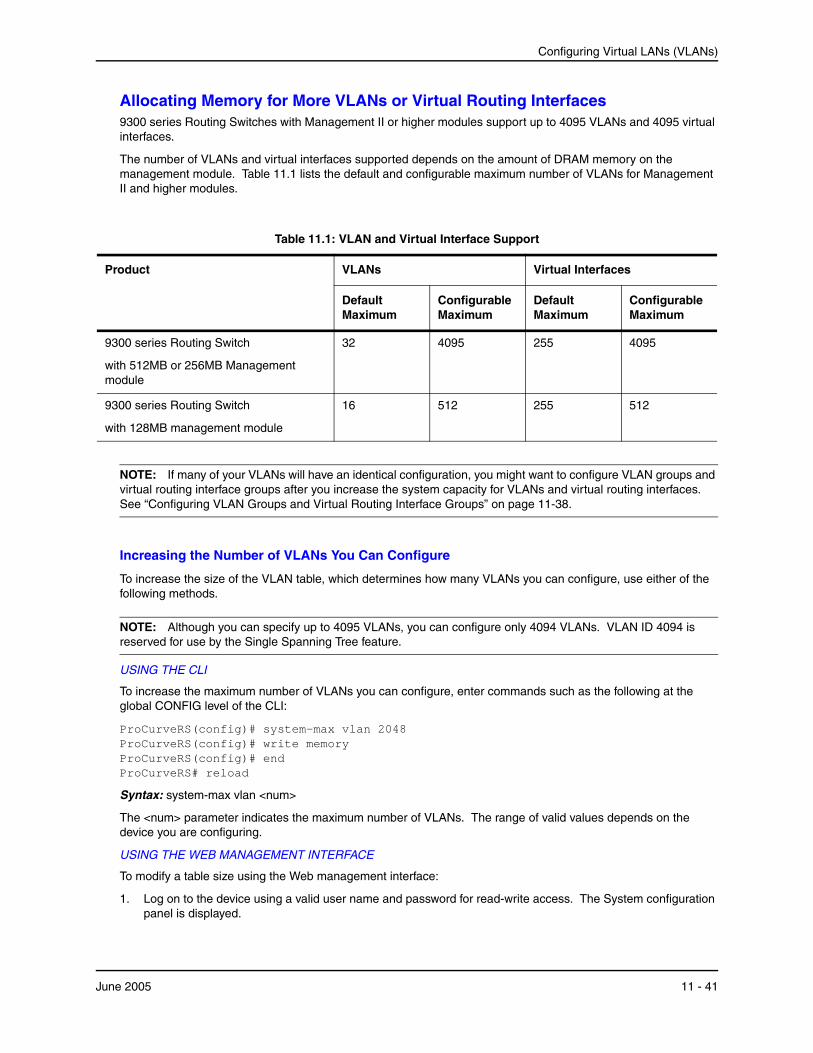
Configuring Virtual LANs (VLANs)
Allocating Memory for More VLANs or Virtual Routing Interfaces9300 series Routing Switches with Management II or higher modules support up to 4095 VLANs and 4095 virtual interfaces.
The number of VLANs and virtual interfaces supported depends on the amount of DRAM memory on the management module. Table 11.1 lists the default and configurable maximum number of VLANs for Management II and higher modules.
Table 11.1: VLAN and Virtual Interface Support
Product VLANs Virtual Interfaces
Default Maximum
Configurable Maximum
Default Maximum
Configurable Maximum
9300 series Routing Switch
with 512MB or 256MB Management module
32 4095 255 4095
9300 series Routing Switch
with 128MB management module
16 512 255 512
NOTE: If many of your VLANs will have an identical configuration, you might want to configure VLAN groups and virtual routing interface groups after you increase the system capacity for VLANs and virtual routing interfaces. See “Configuring VLAN Groups and Virtual Routing Interface Groups” on page 11-38.
Increasing the Number of VLANs You Can Configure
To increase the size of the VLAN table, which determines how many VLANs you can configure, use either of the following methods.
NOTE: Although you can specify up to 4095 VLANs, you can configure only 4094 VLANs. VLAN ID 4094 is reserved for use by the Single Spanning Tree feature.
USING THE CLI
To increase the maximum number of VLANs you can configure, enter commands such as the following at the global CONFIG level of the CLI:
ProCurveRS(config)# system-max vlan 2048 ProCurveRS(config)# write memory ProCurveRS(config)# end ProCurveRS# reload
Syntax: system-max vlan <num>
The <num> parameter indicates the maximum number of VLANs. The range of valid values depends on the device you are configuring.
USING THE WEB MANAGEMENT INTERFACE
To modify a table size using the Web management interface:
1. Log on to the device using a valid user name and password for read-write access. The System configuration panel is displayed.
June 2005 11 - 41
Installation and Basic Configuration Guide for ProCurve 9300 Series Routing Switches
2. Select the Max-Parameter link to display the Configure System Parameter Maximum Value table. This table lists the settings and valid ranges for all the configurable table sizes on the device.
3. Click the Modify button next to the row for the parameter (in this case, “vlan”).
4. Enter the new value for the table size. The value you enter specifies the maximum number of entries the table can hold.
5. Click Apply to save the changes to the device’s running-config.
6. Select the Save link at the bottom of the dialog. Select Yes when prompted to save the configuration change to the startup-config file on the device’s flash memory.
7. Click on the plus sign next to Command in the tree view to list the command options.
8. Select the Reload link and select Yes when the Web management interface asks you whether you really want to reload the software. Changes to cache and table sizes do not take effect until you reload the software.
Increasing the Number of Virtual Routing Interfaces You Can Configure
To increase the size of the virtual routing interface table, which determines how many virtual routing interfaces you can configure, use either of the following methods.
USING THE CLI
To increase the maximum number of virtual routing interfaces you can configure, enter commands such as the following at the global CONFIG level of the CLI:
ProCurveRS(config)# system-max virtual-interface 4095 ProCurveRS(config)# write memory ProCurveRS(config)# end ProCurveRS# reload
Syntax: system-max virtual-interface <num>
The <num> parameter indicates the maximum number of virtual routing interfaces. The range of valid values depends on the device you are configuring. See .
USING THE WEB MANAGEMENT INTERFACE
See the Web management procedure for increasing the VLAN table size, in “Increasing the Number of VLANs You Can Configure” on page 11-41.
Configuring Super Aggregated VLANsYou can aggregate multiple VLANs within another VLAN. This feature allows you to construct Layer 2 paths and channels. This feature is particularly useful for Virtual Private Network (VPN) applications in which you need to provide a private, dedicated Ethernet connection for an individual client to transparently reach its subnet across multiple networks.
A path contains multiple channels, each of which is a dedicated circuit between two end points. The two devices at the end points of the channel appear to each other to be directly attached. The network that connects them is transparent to the two devices.
You can aggregate up to 4094 VLANs within another VLAN. This provides a total VLAN capacity on one HP device of 16,760,836 channels (4094 * 4094).
The devices connected through the channel are not visible to devices in other channels. Therefore, each client has a private link to the other side of the channel.
The feature allows point-to-point and point-to-multipoint connections.
Figure 11.16 shows a conceptual picture of the service that aggregated VLANs provide. Aggregated VLANs provide a path for multiple client channels. The channels do not receive traffic from other channels. Thus, each channel is a private link.
11 - 42 June 2005

Configuring Virtual LANs (VLANs)
Figure 11.16 Conceptual Model of the Super Aggregated VLAN Application
Channel = a client VLAN nestedinside a Path
Client 5Client 3. . . . . .Client 1
sub-net192.168.1.0/24
Path = a single VLAN into whichclient VLANs are aggregated
Client 1192.168.1.69/24
Each client connected to the edge device is in its own port-based VLAN. All the clients’ VLANs are aggregated by the edge device into a single VLAN for connection to the core.
The device that aggregates the VLANs forwards the aggregated VLAN traffic through the core. The core can consist of multiple devices that forward the aggregated VLAN traffic. The edge device at the other end of the core separates the aggregated VLANs into the individual client VLANs before forwarding the traffic. The edge devices forward the individual client traffic to the clients. For the clients’ perspective, the channel is a direct point-to-point link.
Figure 11.17 shows an example application that uses aggregated VLANs. This configuration includes the client connections shown in Figure 11.16.
June 2005 11 - 43
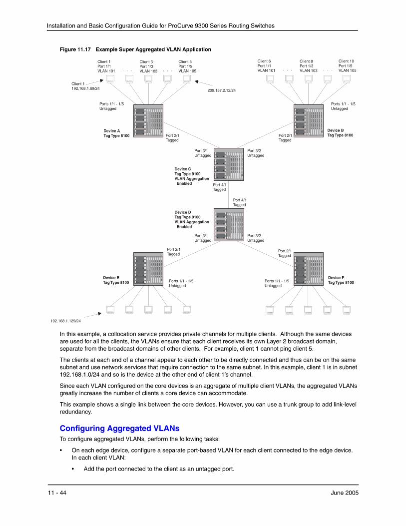
Installation and Basic Configuration Guide for ProCurve 9300 Series Routing Switches
Figure 11.17 Example Super Aggregated VLAN Application
Port 2/1Tagged
Port 3/1Untagged
Port 2/1Tagged
Ports 1/1 - 1/5Untagged
Ports 1/1 - 1/5Untagged
Port 4/1Tagged
Port 3/2Untagged
Port 3/1Untagged
Port 3/2Untagged
Port 4/1Tagged
Port 2/1Tagged
Device DTag Type 9100VLAN AggregationEnabled
Ports 1/1 - 1/5Untagged
Client 10Port 1/5VLAN 105
Client 8Port 1/3VLAN 103. . . . . .
Port 2/1Tagged
Device ATag Type 8100
Device ETag Type 8100
Device BTag Type 8100
Device FTag Type 8100
Device CTag Type 9100VLAN AggregationEnabled
192.168.1.129/24
Client 6Port 1/1VLAN 101
Client 5Port 1/5VLAN 105
Client 3Port 1/3VLAN 103. . . . . .
Client 1Port 1/1VLAN 101
Ports 1/1 - 1/5Untagged
209.157.2.12/24
Client 1192.168.1.69/24
In this example, a collocation service provides private channels for multiple clients. Although the same devices are used for all the clients, the VLANs ensure that each client receives its own Layer 2 broadcast domain, separate from the broadcast domains of other clients. For example, client 1 cannot ping client 5.
The clients at each end of a channel appear to each other to be directly connected and thus can be on the same subnet and use network services that require connection to the same subnet. In this example, client 1 is in subnet 192.168.1.0/24 and so is the device at the other end of client 1’s channel.
Since each VLAN configured on the core devices is an aggregate of multiple client VLANs, the aggregated VLANs greatly increase the number of clients a core device can accommodate.
This example shows a single link between the core devices. However, you can use a trunk group to add link-level redundancy.
Configuring Aggregated VLANsTo configure aggregated VLANs, perform the following tasks:
• On each edge device, configure a separate port-based VLAN for each client connected to the edge device. In each client VLAN:
• Add the port connected to the client as an untagged port.
11 - 44 June 2005

Configuring Virtual LANs (VLANs)
• Add the port connected to the core device (the device that will aggregate the VLANs) as a tagged port. This port must be tagged because all the client VLANs share the port as an uplink to the core device.
• On each core device:
• Enable VLAN aggregation. This support allows the core device to add an additional tag to each Ethernet frame that contains a VLAN packet from the edge device. The additional tag identifies the aggregate VLAN (the path). However, the additional tag can cause the frame to be longer than the maximum supported frame size. The larger frame support allows Ethernet frames up to 1530 bytes long.
NOTE: Enable the VLAN aggregation option only on the core devices.
• Configure a VLAN tag type (tag ID) that is different than the tag type used on the edge devices. If you use the default tag type (8100) on the edge devices, set the tag type on the core devices to another value, such as 9100. The tag type must be the same on all the core devices. The edge devices also must have the same tag type but the type must be different from the tag type on the core devices.
NOTE: You can enable the Spanning Tree Protocol (STP) on the edge devices or the core devices, but not both. If you enable STP on the edge devices and the core devices, STP will prevent client traffic from travelling through the core to the other side.
Configuring Aggregated VLANs on an Edge Device
To configure aggregated VLANs on an edge device, use one of the following methods.
USING THE CLI
To configure the aggregated VLANs on device A in Figure 11.17 on page 11-44, enter the following commands:
ProCurveRS(config)# vlan 101 by port ProCurveRS(config-vlan-101)# tagged ethernet 2/1 ProCurveRS(config-vlan-101)# untagged ethernet 1/1 ProCurveRS(config-vlan-101)# exit ProCurveRS(config)# vlan 102 by port ProCurveRS(config-vlan-102)# tagged ethernet 2/1 ProCurveRS(config-vlan-102)# untagged ethernet 1/2 ProCurveRS(config-vlan-102)# exit ProCurveRS(config)# vlan 103 by port ProCurveRS(config-vlan-103)# tagged ethernet 2/1 ProCurveRS(config-vlan-103)# untagged ethernet 1/3 ProCurveRS(config-vlan-103)# exit ProCurveRS(config)# vlan 104 by port ProCurveRS(config-vlan-104)# tagged ethernet 2/1 ProCurveRS(config-vlan-104)# untagged ethernet 1/4 ProCurveRS(config-vlan-104)# exit ProCurveRS(config)# vlan 105 by port ProCurveRS(config-vlan-105)# tagged ethernet 2/1 ProCurveRS(config-vlan-105)# untagged ethernet 1/5 ProCurveRS(config-vlan-105)# exit ProCurveRS(config)# write memory
Syntax: [no] vlan <vlan-id> [by port]
Syntax: [no] tagged ethernet <portnum> [to <portnum> | ethernet <portnum>]
Syntax: [no] untagged ethernet <portnum> [to <portnum> | ethernet <portnum>]
Use the tagged command to add the port that the device uses for the uplink to the core device. Use the untagged command to add the ports connected to the individual clients.
June 2005 11 - 45
Installation and Basic Configuration Guide for ProCurve 9300 Series Routing Switches
USING THE WEB MANAGEMENT INTERFACE
You cannot enable VLAN aggregation using the Web management interface. The other options you need for configuring Aggregated VLANs are present in earlier software releases and are supported in the Web management interface.
Configuring Aggregated VLANs on a Core Device
To configure aggregated VLANs on a core device, use one of the following methods.
USING THE CLI
To configure the aggregated VLANs on device C in Figure 11.17 on page 11-44, enter the following commands:
ProCurveRS(config)# tag-type 9100 ProCurveRS(config)# aggregated-vlan ProCurveRS(config)# vlan 101 by port ProCurveRS(config-vlan-101)# tagged ethernet 4/1 ProCurveRS(config-vlan-101)# untagged ethernet 3/1 ProCurveRS(config-vlan-101)# exit ProCurveRS(config)# vlan 102 by port ProCurveRS(config-vlan-102)# tagged ethernet 4/1 ProCurveRS(config-vlan-102)# untagged ethernet 3/2 ProCurveRS(config-vlan-102)# exit ProCurveRS(config)# write memory
Syntax: [no] tag-type <num>
Syntax: [no] aggregated-vlan
The <num> parameter specifies the tag type can be a hexadecimal value from 0 – ffff. The default is 8100.
USING THE WEB MANAGEMENT INTERFACE
You cannot enable VLAN aggregation using the Web management interface.
Verifying the ConfigurationYou can verify the VLAN, VLAN aggregation option, and tag configuration by viewing the running-config. To display the running-config, enter the show running-config command from any CLI prompt. After you save the configuration changes to the startup-config, you also can display the settings in that file by entering the show configuration command from any CLI prompt.
Complete CLI ExamplesThe following sections show all the Aggregated VLAN configuration commands on the devices in Figure 11.17 on page 11-44.
NOTE: In these examples, the configurations of the edge devices (A, B, E, and F) are identical. The configurations of the core devices (C and D) also are identical. The aggregated VLAN configurations of the edge and core devices on one side must be symmetrical (in fact, a mirror image) to the configurations of the devices on the other side. For simplicity, the example in Figure 11.17 on page 11-44 is symmetrical in terms of the port numbers. This allows the configurations for both sides of the link to be the same. If your configuration does not use symmetrically arranged port numbers, the configurations should not be identical but must use the correct port numbers.
Commands for Device A
ProCurveRSA(config)# vlan 101 by port ProCurveRSA(config-vlan-101)# tagged ethernet 2/1 ProCurveRSA(config-vlan-101)# untagged ethernet 1/1 ProCurveRSA(config-vlan-101)# exit ProCurveRSA(config)# vlan 102 by port
11 - 46 June 2005
Configuring Virtual LANs (VLANs)
ProCurveRSA(config-vlan-102)# tagged ethernet 2/1 ProCurveRSA(config-vlan-102)# untagged ethernet 1/2 ProCurveRSA(config-vlan-102)# exit ProCurveRSA(config)# vlan 103 by port ProCurveRSA(config-vlan-103)# tagged ethernet 2/1 ProCurveRSA(config-vlan-103)# untagged ethernet 1/3 ProCurveRSA(config-vlan-103)# exit ProCurveRSA(config)# vlan 104 by port ProCurveRSA(config-vlan-104)# tagged ethernet 2/1 ProCurveRSA(config-vlan-104)# untagged ethernet 1/4 ProCurveRSA(config-vlan-104)# exit ProCurveRSA(config)# vlan 105 by port ProCurveRSA(config-vlan-105)# tagged ethernet 2/1 ProCurveRSA(config-vlan-105)# untagged ethernet 1/5 ProCurveRSA(config-vlan-105)# exit ProCurveRSA(config)# write memory
Commands for Device B
The commands for configuring device B are identical to the commands for configuring device A. Notice that you can use the same channel VLAN numbers on each device. The devices that aggregate the VLANs into a path can distinguish between the identically named channel VLANs based on the ID of the path VLAN.
ProCurveRSB(config)# vlan 101 by port ProCurveRSB(config-vlan-101)# tagged ethernet 2/1 ProCurveRSB(config-vlan-101)# untagged ethernet 1/1 ProCurveRSB(config-vlan-101)# exit ProCurveRSB(config)# vlan 102 by port ProCurveRSB(config-vlan-102)# tagged ethernet 2/1 ProCurveRSB(config-vlan-102)# untagged ethernet 1/2 ProCurveRSB(config-vlan-102)# exit ProCurveRSB(config)# vlan 103 by port ProCurveRSB(config-vlan-103)# tagged ethernet 2/1 ProCurveRSB(config-vlan-103)# untagged ethernet 1/3 ProCurveRSB(config-vlan-103)# exit ProCurveRSB(config)# vlan 104 by port ProCurveRSB(config-vlan-104)# tagged ethernet 2/1 ProCurveRSB(config-vlan-104)# untagged ethernet 1/4 ProCurveRSB(config-vlan-104)# exit ProCurveRSB(config)# vlan 105 by port ProCurveRSB(config-vlan-105)# tagged ethernet 2/1 ProCurveRSB(config-vlan-105)# untagged ethernet 1/5 ProCurveRSB(config-vlan-105)# exit ProCurveRSB(config)# write memory
Commands for Device C
Since device C is aggregating channel VLANs from devices A and B into a single path, you need to change the tag type and enable VLAN aggregation.
ProCurveRSC(config)# tag-type 9100 ProCurveRSC(config)# aggregated-vlan ProCurveRSC(config)# vlan 101 by port ProCurveRSC(config-vlan-101)# tagged ethernet 4/1 ProCurveRSC(config-vlan-101)# untagged ethernet 3/1 ProCurveRSC(config-vlan-101)# exit ProCurveRSC(config)# vlan 102 by port ProCurveRSC(config-vlan-102)# tagged ethernet 4/1 ProCurveRSC(config-vlan-102)# untagged ethernet 3/2 ProCurveRSC(config-vlan-102)# exit ProCurveRSC(config)# write memory
June 2005 11 - 47

Installation and Basic Configuration Guide for ProCurve 9300 Series Routing Switches
Commands for Device D
Device D is at the other end of path and separates the channels back into individual VLANs. The tag type must be the same as tag type configured on the other core device (Device C). In addition, VLAN aggregation also must be enabled.
ProCurveRSD(config)# tag-type 9100 ProCurveRSD(config)# aggregated-vlan ProCurveRSD(config)# vlan 101 by port ProCurveRSD(config-vlan-101)# tagged ethernet 4/1 ProCurveRSD(config-vlan-101)# untagged ethernet 3/1 ProCurveRSD(config-vlan-101)# exit ProCurveRSD(config)# vlan 102 by port ProCurveRSD(config-vlan-102)# tagged ethernet 4/1 ProCurveRSD(config-vlan-102)# untagged ethernet 3/2 ProCurveRSD(config-vlan-102)# exit ProCurveRSD(config)# write memory
Commands for Device E
Since the configuration in Figure 11.17 on page 11-44 is symmetrical, the commands for configuring device E are identical to the commands for configuring device A.
ProCurveRSE(config)# vlan 101 by port ProCurveRSE(config-vlan-101)# tagged ethernet 2/1 ProCurveRSE(config-vlan-101)# untagged ethernet 1/1 ProCurveRSE(config-vlan-101)# exit ProCurveRSE(config)# vlan 102 by port ProCurveRSE(config-vlan-102)# tagged ethernet 2/1 ProCurveRSE(config-vlan-102)# untagged ethernet 1/2 ProCurveRSE(config-vlan-102)# exit ProCurveRSE(config)# vlan 103 by port ProCurveRSE(config-vlan-103)# tagged ethernet 2/1 ProCurveRSE(config-vlan-103)# untagged ethernet 1/3 ProCurveRSE(config-vlan-103)# exit ProCurveRSE(config)# vlan 104 by port ProCurveRSE(config-vlan-104)# tagged ethernet 2/1 ProCurveRSE(config-vlan-104)# untagged ethernet 1/4 ProCurveRSE(config-vlan-104)# exit ProCurveRSE(config)# vlan 105 by port ProCurveRSE(config-vlan-105)# tagged ethernet 2/1 ProCurveRSE(config-vlan-105)# untagged ethernet 1/5 ProCurveRSE(config-vlan-105)# exit ProCurveRSE(config)# write memory
Commands for Device F
The commands for configuring device F are identical to the commands for configuring device E. In this example, since the port numbers on each side of the configuration in Figure 11.17 on page 11-44 are symmetrical, the configuration of device F is also identical to the configuration of device A and device B.
ProCurveRSF(config)# vlan 101 by port ProCurveRSF(config-vlan-101)# tagged ethernet 2/1 ProCurveRSF(config-vlan-101)# untagged ethernet 1/1 ProCurveRSF(config-vlan-101)# exit ProCurveRSF(config)# vlan 102 by port ProCurveRSF(config-vlan-102)# tagged ethernet 2/1 ProCurveRSF(config-vlan-102)# untagged ethernet 1/2 ProCurveRSF(config-vlan-102)# exit ProCurveRSF(config)# vlan 103 by port ProCurveRSF(config-vlan-103)# tagged ethernet 2/1 ProCurveRSF(config-vlan-103)# untagged ethernet 1/3
11 - 48 June 2005
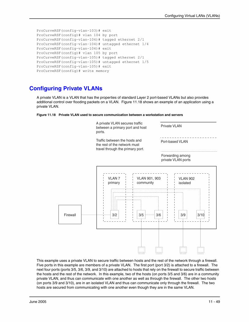
Configuring Virtual LANs (VLANs)
ProCurveRSF(config-vlan-103)# exit ProCurveRSF(config)# vlan 104 by port ProCurveRSF(config-vlan-104)# tagged ethernet 2/1 ProCurveRSF(config-vlan-104)# untagged ethernet 1/4 ProCurveRSF(config-vlan-104)# exit ProCurveRSF(config)# vlan 105 by port ProCurveRSF(config-vlan-105)# tagged ethernet 2/1 ProCurveRSF(config-vlan-105)# untagged ethernet 1/5 ProCurveRSF(config-vlan-105)# exit ProCurveRSF(config)# write memory
Configuring Private VLANsA private VLAN is a VLAN that has the properties of standard Layer 2 port-based VLANs but also provides additional control over flooding packets on a VLAN. Figure 11.18 shows an example of an application using a private VLAN.
Figure 11.18 Private VLAN used to secure communication between a workstation and servers
Private VLAN
Forwarding amongprivate VLAN ports
VLAN 7primary
3/9 3/10
VLAN 902isolated
VLAN 901, 903community
3/2
A private VLAN secures trafficbetween a primary port and hostports.
Traffic between the hosts andthe rest of the network musttravel through the primary port.
Port-based VLAN
3/5 3/6Firewall
This example uses a private VLAN to secure traffic between hosts and the rest of the network through a firewall. Five ports in this example are members of a private VLAN. The first port (port 3/2) is attached to a firewall. The next four ports (ports 3/5, 3/6, 3/9, and 3/10) are attached to hosts that rely on the firewall to secure traffic between the hosts and the rest of the network. In this example, two of the hosts (on ports 3/5 and 3/6) are in a community private VLAN, and thus can communicate with one another as well as through the firewall. The other two hosts (on ports 3/9 and 3/10), are in an isolated VLAN and thus can communicate only through the firewall. The two hosts are secured from communicating with one another even though they are in the same VLAN.
June 2005 11 - 49

Installation and Basic Configuration Guide for ProCurve 9300 Series Routing Switches
By default, the private VLAN does not forward broadcast or unknown-unicast packets from outside sources into the private VLAN. If needed, you can override this behavior for broadcast packets, unknown-unicast packets, or both. (See “Enabling Broadcast or Unknown Unicast Traffic to the Private VLAN” on page 11-52.)
You can configure a combination of the following types of private VLANs:
• Primary – The primary private VLAN ports are “promiscuous”. They can communicate with all the isolated private VLAN ports and community private VLAN ports in the isolated and community VLANs that are mapped to the promiscuous port.
• Isolated – Broadcasts and unknown unicasts received on isolated ports are sent only to the primary port. They are not flooded to other ports in the isolated VLAN.
• Community – Broadcasts and unknown unicasts received on community ports are sent to the primary port and also are flooded to the other ports in the community VLAN.
Each private VLAN must have a primary VLAN. The primary VLAN is the interface between the secured ports and the rest of the network. The private VLAN can have any combination of community and isolated VLANs. (See “Configuration Rules” on page 11-50.)
Table 11.2 list the differences between private VLANs and standard VLANs.
Table 11.2: Comparison of Private VLANs and Standard Port-Based VLANs
Forwarding Behavior Private VLANs Standard VLANs
All ports within a VLAN constitute a common Layer broadcast domain
No Yes
Broadcasts and unknown unicasts are forwarded to all the VLAN’s ports by default
No (isolated VLAN)
Yes (community VLAN)
Yes
Known unicasts Yes Yes
Implementation Notes• The private VLAN implementation in the current release uses the CPU for forwarding packets on the primary
VLAN’s “promiscuous” port. Other forwarding is performed in the hardware. Support for the hardware forwarding in this feature sometimes results in multiple MAC address entries for the same MAC address in the device’s MAC address table. In this case, each of the entries is associated with a different VLAN. The multiple entries are a normal aspect of the implementation of this feature and do not indicate a software problem.
• By default, the primary VLAN does not forward broadcast or unknown unicast packets into the private VLAN. You also can use MAC address filters to control traffic forwarded into and out of the private VLAN.
Configuring a Private VLANTo configure a private VLAN, configure each of the component VLANs (isolated, community, and public) as a separate port-based VLAN.
• Use standard VLAN configuration commands to create the VLAN and add ports.
• Identify the type private VLAN type (isolated, community, or public)
• For the primary VLAN, map the other private VLANs to the port(s) in the primary VLAN
Configuration Rules
• You can use 10/100 and Gigabit Ethernet ports in a private VLAN.
• You cannot configure any of the ports in a private VLAN to be members of a trunk group.
11 - 50 June 2005
Configuring Virtual LANs (VLANs)
• You cannot share a port between a private VLAN and a standard port-based VLAN or protocol VLAN. You can configure private VLANs and standard port-based VLANs and protocol VLANs on the same device, but a port cannot be a member of both a private VLAN and a port-based VLAN or protocol VLAN.
NOTE: Although a private VLAN resides within a port-based VLAN, the VLAN is considered to be exclusively a private VLAN, not a port-based VLAN.
• You cannot use the private VLAN feature and the dual-mode VLAN port feature on the same device.
• The Spanning Tree Protocol (STP) is independent of this feature, and can be enabled or disabled in the individual port-based VLANs. However, private VLANs are not supported with single-instance STP (“single span”).
• You can configure only one private VLAN within a given port-based VLAN. Thus, you must configure a separate port-based VLAN for each private VLAN.
• Each private VLAN can have only one primary VLAN.
• Each private VLAN can have multiple isolated or community VLANs. You can use any combination of isolated or community VLANs with the primary VLAN. You do not need to use both isolated and community VLANs in the private VLAN.
• You can configure the primary VLAN before or after you configure the community or isolated VLANs. You are not required to configure a specific type of private VLAN before you can configure the other types.
• The ports in all three types of private VLANs can be tagged or untagged.
NOTE: If the port in the primary VLAN is tagged, you must add the port as a tagged port to each of the isolated and community VLANs. If the port in the primary VLAN is untagged, you do not need to add the port to the isolated and community VLANs.
• The primary VLAN has only one active port. The primary VLAN can have more than one port, but only the lowest-numbered available port is active. The other ports provide redundancy.
• You cannot configure the default VLAN (VLAN 1) as a private VLAN.
Configuring an Isolated or Community Private VLAN
To configure an isolated or a community private VLAN, use the following CLI methods.
USING THE CLI
To configure a community private VLAN, enter commands such as the following:
ProCurveRS(config)# vlan 901 ProCurveRS(config-vlan-901)# tagged ethernet 3/5 to 3/6 ProCurveRS(config-vlan-901)# pvlan type community
These commands create port-based VLAN 901, add ports 3/5 and 3/6 to the VLAN as tagged ports, then specify that the VLAN is a community private VLAN.
Syntax: tagged ethernet <portnum> [to <portnum> | ethernet <portnum>]
Syntax: [no] pvlan type community | isolated | primary
The tagged or untagged command adds the ports to the VLAN.
The pvlan type command specifies that this port-based VLAN is a private VLAN.
• community – Broadcasts and unknown unicasts received on community ports are sent to the primary port and also are flooded to the other ports in the community VLAN.
• isolated – Broadcasts and unknown unicasts received on isolated ports are sent only to the primary port. They are not flooded to other ports in the isolated VLAN.
• primary – The primary private VLAN ports are “promiscuous”. They can communicate with all the isolated private VLAN ports and community private VLAN ports in the isolated and community VLANs that are
June 2005 11 - 51
Installation and Basic Configuration Guide for ProCurve 9300 Series Routing Switches
mapped to the promiscuous port.
Configuring the Primary VLAN
Use the following CLI method to configure the primary VLAN.
NOTE: The primary private VLAN has only one active port. If you configure the VLAN to have more than one port, the lowest-numbered port is the active one. The additional ports provide redundancy. If the active port becomes unavailable, the lowest-numbered available port becomes the active port for the VLAN.
USING THE CLI
To configure a primary private VLAN, enter commands such as the following:
ProCurveRS(config)# vlan 7 ProCurveRS(config-vlan-7)# untagged ethernet 3/2 ProCurveRS(config-vlan-7)# pvlan type primary ProCurveRS(config-vlan-7)# pvlan mapping 901 ethernet 3/2
These commands create port-based VLAN 7, add port 3/2 as an untagged port, identify the VLAN as the primary VLAN in a private VLAN, and map the other private VLANs to the port(s) in this VLAN.
Syntax: untagged ethernet <portnum> [to <portnum> | ethernet <portnum>]
Syntax: [no] pvlan type community | isolated | primary
Syntax: [no] pvlan mapping <vlan-id> ethernet <portnum>
The tagged or untagged command adds the port(s) to the VLAN.
NOTE: You can add the port as a tagged port if needed. If you add the port as a tagged port, you must also add the port as a tagged port to the isolated and community VLANs. See “CLI Example for Figure 11.18” on page 11-53.
The pvlan type command specifies that this port-based VLAN is a private VLAN. Specify primary as the type.
The pvlan mapping command identifies the other private VLANs for which this VLAN is the primary. The command also specifies the primary VLAN ports to which you are mapping the other private VLANs.
• The <vlan-id> parameter specifies another private VLAN. The other private VLAN you want to specify must already be configured.
• The ethernet <portnum> parameter specifies the primary VLAN port to which you are mapping all the ports in the other private VLAN (the one specified by <vlan-id>).
Enabling Broadcast or Unknown Unicast Traffic to the Private VLANTo enhance private VLAN security, the primary private VLAN does not forward broadcast or unknown unicast packets to its community and isolated VLANs. For example, if port 3/2 in Figure 11.18 on page 11-49 receives a broadcast packet from the firewall, the port does not forward the packet to the other private VLAN ports (3/5, 3/6, 3/9, and 3/10).
This forwarding restriction does not apply to traffic from the private VLAN. The primary port does forward broadcast and unknown unicast packets that are received from the isolated and community VLANs. For example, if the host on port 3/9 sends an unknown unicast packet, port 3/2 forwards the packet to the firewall.
If you want to remove the forwarding restriction, you can enable the primary port to forward broadcast or unknown unicast traffic, if desired, using the following CLI method. You can enable or disable forwarding of broadcast or unknown unicast packets separately.
NOTE: You also can use MAC address filters to control the traffic forwarded into and out of the private VLAN.
11 - 52 June 2005
Configuring Virtual LANs (VLANs)
USING THE CLI
To configure the ports in the primary VLAN to forward broadcast or unknown unicast traffic received from sources outside the private VLAN, enter the following commands at the global CONFIG level of the CLI:
ProCurveRS(config)# pvlan-preference broadcast flood ProCurveRS(config)# pvlan-preference unknown-unicast flood
These commands enable forwarding of broadcast and unknown-unicast packets to ports within the private VLAN. To again disable forwarding, enter a command such as the following:
ProCurveRS(config)# no pvlan-preference broadcast flood
This command disables forwarding of broadcast packets within the private VLAN.
Syntax: [no] pvlan-preference broadcast | unknown-unicast flood
CLI Example for Figure 11.18To configure the private VLANs shown in Figure 11.18 on page 11-49, enter the following commands:
ProCurveRS(config)# vlan 901 ProCurveRS(config-vlan-901)# tagged ethernet 3/5 to 3/6 ProCurveRS(config-vlan-901)# pvlan type community ProCurveRS(config-vlan-901)# exit ProCurveRS(config)# vlan 902 ProCurveRS(config-vlan-902)# tagged ethernet 3/9 to 3/10 ProCurveRS(config-vlan-902)# pvlan type isolated ProCurveRS(config-vlan-902)# exit ProCurveRS(config)# vlan 903 ProCurveRS(config-vlan-903)# tagged ethernet 3/5 to 3/6 ProCurveRS(config-vlan-903)# pvlan type community ProCurveRS(config-vlan-903)# exit ProCurveRS(config)# vlan 7 ProCurveRS(config-vlan-7)# untagged ethernet 3/2 ProCurveRS(config-vlan-7)# pvlan type primary ProCurveRS(config-vlan-7)# pvlan mapping 901 ethernet 3/2 ProCurveRS(config-vlan-7)# pvlan mapping 902 ethernet 3/2 ProCurveRS(config-vlan-7)# pvlan mapping 903 ethernet 3/2
This example assumes that the port in the primary private VLAN is untagged. If the port in the primary VLAN is tagged, you must add the port as a tagged port to the isolated and community VLANs, as in the following example:
ProCurveRS(config)# vlan 901 ProCurveRS(config-vlan-901)# tagged ethernet 3/5 to 3/6 ProCurveRS(config-vlan-901)# tagged ethernet 3/2 ProCurveRS(config-vlan-901)# pvlan type community ProCurveRS(config-vlan-901)# exit ProCurveRS(config)# vlan 902 ProCurveRS(config-vlan-902)# tagged ethernet 3/9 to 3/10 ProCurveRS(config-vlan-902)# tagged ethernet 3/2 ProCurveRS(config-vlan-902)# pvlan type isolated ProCurveRS(config-vlan-902)# exit ProCurveRS(config)# vlan 903 ProCurveRS(config-vlan-903)# tagged ethernet 3/5 to 3/6 ProCurveRS(config-vlan-903)# tagged ethernet 3/2 ProCurveRS(config-vlan-903)# pvlan type community ProCurveRS(config-vlan-903)# exit ProCurveRS(config)# vlan 7 ProCurveRS(config-vlan-7)# tagged ethernet 3/2 ProCurveRS(config-vlan-7)# pvlan type primary ProCurveRS(config-vlan-7)# pvlan mapping 901 ethernet 3/2 ProCurveRS(config-vlan-7)# pvlan mapping 902 ethernet 3/2
June 2005 11 - 53
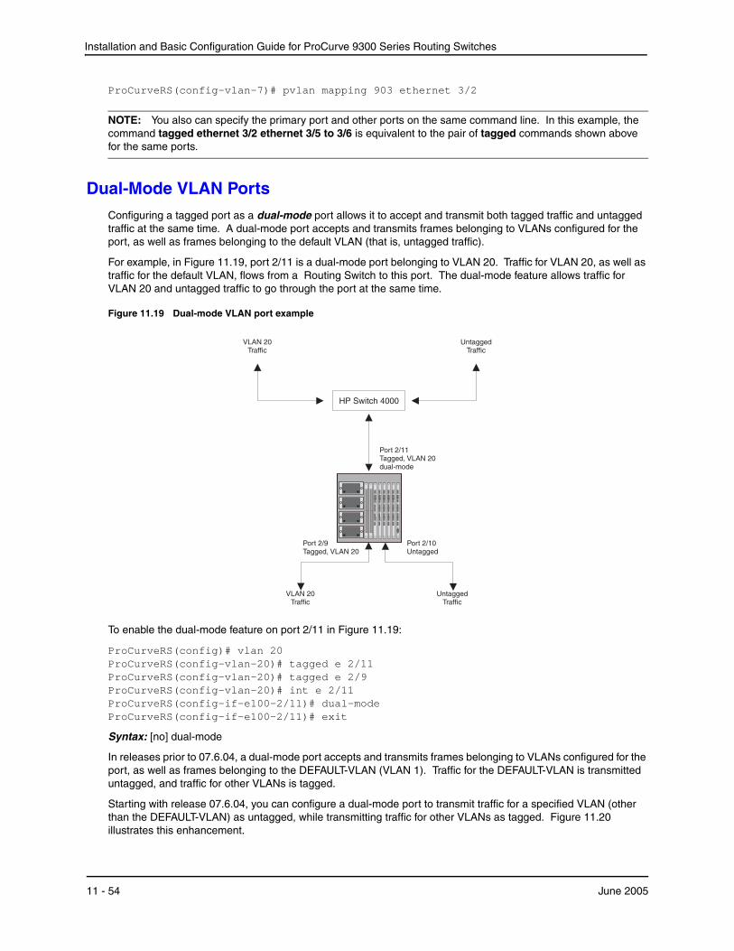
Installation and Basic Configuration Guide for ProCurve 9300 Series Routing Switches
ProCurveRS(config-vlan-7)# pvlan mapping 903 ethernet 3/2
NOTE: You also can specify the primary port and other ports on the same command line. In this example, the command tagged ethernet 3/2 ethernet 3/5 to 3/6 is equivalent to the pair of tagged commands shown above for the same ports.
Dual-Mode VLAN PortsConfiguring a tagged port as a dual-mode port allows it to accept and transmit both tagged traffic and untagged traffic at the same time. A dual-mode port accepts and transmits frames belonging to VLANs configured for the port, as well as frames belonging to the default VLAN (that is, untagged traffic).
For example, in Figure 11.19, port 2/11 is a dual-mode port belonging to VLAN 20. Traffic for VLAN 20, as well as traffic for the default VLAN, flows from a Routing Switch to this port. The dual-mode feature allows traffic for VLAN 20 and untagged traffic to go through the port at the same time.
Figure 11.19 Dual-mode VLAN port example
HP Switch 4000
Port 2/11Tagged, VLAN 20dual-mode
Port 2/9Tagged, VLAN 20
Port 2/10Untagged
UntaggedTraffic
VLAN 20Traffic
UntaggedTraffic
VLAN 20Traffic
To enable the dual-mode feature on port 2/11 in Figure 11.19:
ProCurveRS(config)# vlan 20 ProCurveRS(config-vlan-20)# tagged e 2/11 ProCurveRS(config-vlan-20)# tagged e 2/9 ProCurveRS(config-vlan-20)# int e 2/11 ProCurveRS(config-if-e100-2/11)# dual-mode ProCurveRS(config-if-e100-2/11)# exit
Syntax: [no] dual-mode
In releases prior to 07.6.04, a dual-mode port accepts and transmits frames belonging to VLANs configured for the port, as well as frames belonging to the DEFAULT-VLAN (VLAN 1). Traffic for the DEFAULT-VLAN is transmitted untagged, and traffic for other VLANs is tagged.
Starting with release 07.6.04, you can configure a dual-mode port to transmit traffic for a specified VLAN (other than the DEFAULT-VLAN) as untagged, while transmitting traffic for other VLANs as tagged. Figure 11.20 illustrates this enhancement.
11 - 54 June 2005
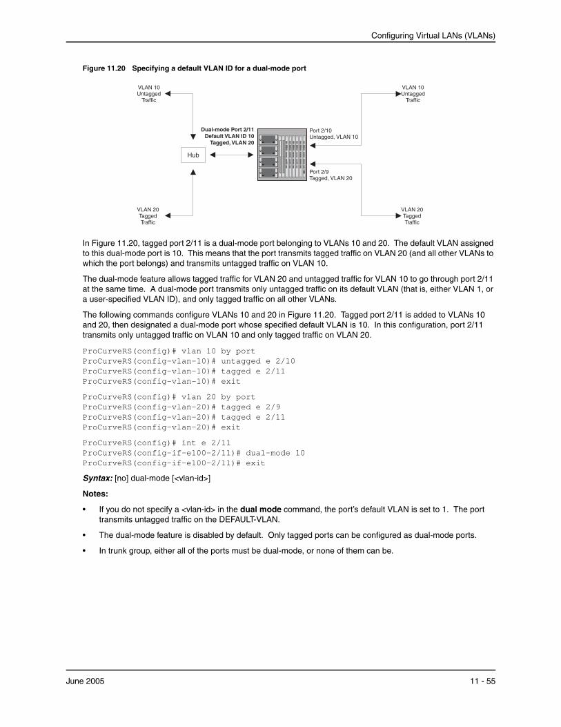
Configuring Virtual LANs (VLANs)
Figure 11.20 Specifying a default VLAN ID for a dual-mode port
VLAN 10Untagged
Traffic
Port 2/9Tagged, VLAN 20
Port 2/10Untagged, VLAN 10
VLAN 20TaggedTraffic
Hub
Dual-modeDefault VLAN ID 10
Port 2/11
Tagged, VLAN 20
VLAN 10Untagged
Traffic
VLAN 20TaggedTraffic
In Figure 11.20, tagged port 2/11 is a dual-mode port belonging to VLANs 10 and 20. The default VLAN assigned to this dual-mode port is 10. This means that the port transmits tagged traffic on VLAN 20 (and all other VLANs to which the port belongs) and transmits untagged traffic on VLAN 10.
The dual-mode feature allows tagged traffic for VLAN 20 and untagged traffic for VLAN 10 to go through port 2/11 at the same time. A dual-mode port transmits only untagged traffic on its default VLAN (that is, either VLAN 1, or a user-specified VLAN ID), and only tagged traffic on all other VLANs.
The following commands configure VLANs 10 and 20 in Figure 11.20. Tagged port 2/11 is added to VLANs 10 and 20, then designated a dual-mode port whose specified default VLAN is 10. In this configuration, port 2/11 transmits only untagged traffic on VLAN 10 and only tagged traffic on VLAN 20.
ProCurveRS(config)# vlan 10 by port ProCurveRS(config-vlan-10)# untagged e 2/10 ProCurveRS(config-vlan-10)# tagged e 2/11 ProCurveRS(config-vlan-10)# exit
ProCurveRS(config)# vlan 20 by port ProCurveRS(config-vlan-20)# tagged e 2/9 ProCurveRS(config-vlan-20)# tagged e 2/11 ProCurveRS(config-vlan-20)# exit
ProCurveRS(config)# int e 2/11 ProCurveRS(config-if-e100-2/11)# dual-mode 10 ProCurveRS(config-if-e100-2/11)# exit
Syntax: [no] dual-mode [<vlan-id>]
Notes:
• If you do not specify a <vlan-id> in the dual mode command, the port’s default VLAN is set to 1. The port transmits untagged traffic on the DEFAULT-VLAN.
• The dual-mode feature is disabled by default. Only tagged ports can be configured as dual-mode ports.
• In trunk group, either all of the ports must be dual-mode, or none of them can be.
June 2005 11 - 55
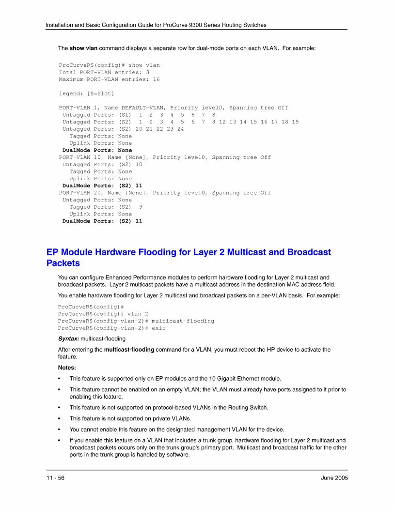
Installation and Basic Configuration Guide for ProCurve 9300 Series Routing Switches
The show vlan command displays a separate row for dual-mode ports on each VLAN. For example:
ProCurveRS(config)# show vlan Total PORT-VLAN entries: 3 Maximum PORT-VLAN entries: 16 legend: [S=Slot] PORT-VLAN 1, Name DEFAULT-VLAN, Priority level0, Spanning tree Off Untagged Ports: (S1) 1 2 3 4 5 6 7 8 Untagged Ports: (S2) 1 2 3 4 5 6 7 8 12 13 14 15 16 17 18 19 Untagged Ports: (S2) 20 21 22 23 24 Tagged Ports: None Uplink Ports: None DualMode Ports: None PORT-VLAN 10, Name [None], Priority level0, Spanning tree Off Untagged Ports: (S2) 10 Tagged Ports: None Uplink Ports: None DualMode Ports: (S2) 11 PORT-VLAN 20, Name [None], Priority level0, Spanning tree Off Untagged Ports: None Tagged Ports: (S2) 9 Uplink Ports: None DualMode Ports: (S2) 11
EP Module Hardware Flooding for Layer 2 Multicast and Broadcast Packets
You can configure Enhanced Performance modules to perform hardware flooding for Layer 2 multicast and broadcast packets. Layer 2 multicast packets have a multicast address in the destination MAC address field.
You enable hardware flooding for Layer 2 multicast and broadcast packets on a per-VLAN basis. For example:
ProCurveRS(config)# ProCurveRS(config)# vlan 2 ProCurveRS(config-vlan-2)# multicast-flooding ProCurveRS(config-vlan-2)# exit
Syntax: multicast-flooding
After entering the multicast-flooding command for a VLAN, you must reboot the HP device to activate the feature.
Notes:
• This feature is supported only on EP modules and the 10 Gigabit Ethernet module.
• This feature cannot be enabled on an empty VLAN; the VLAN must already have ports assigned to it prior to enabling this feature.
• This feature is not supported on protocol-based VLANs in the Routing Switch.
• This feature is not supported on private VLANs.
• You cannot enable this feature on the designated management VLAN for the device.
• If you enable this feature on a VLAN that includes a trunk group, hardware flooding for Layer 2 multicast and broadcast packets occurs only on the trunk group’s primary port. Multicast and broadcast traffic for the other ports in the trunk group is handled by software.
11 - 56 June 2005

Configuring Virtual LANs (VLANs)
Configuring VLANs Using the Web Management InterfaceUse the procedures in the following sections to configure VLANs using the Web management interface.
Configuring a Port-Based VLAN1. Log on to the device using a valid user name and password for read-write access.
2. If you have not already enabled OSPF, enable it by clicking on the Enable radio button next to OSPF on the System configuration dialog, then clicking Apply to apply the change.
3. Click on the plus sign next to Configure in the tree view to expand the list of configuration options.
4. Click on the plus sign next to VLAN in the tree view to expand the list of VLAN option links.
5. Click on the Port link.
• If the device does not have any port-based VLANs, the Port VLAN configuration panel is displayed, as shown in the following example.
• If at least one port-based VLAN is already configured and you are adding a new one, click on the Add Port VLAN link to display the Port VLAN configuration panel, as shown in the following example.
• If you are modifying an existing port-based VLAN, click on the Modify button to the right of the row describing the VLAN to display the Port VLAN configuration panel, as shown in the following example.
6. Enter the VLAN ID and optionally the name.
7. If you want to assign the VLAN to a different Quality of Service (QoS) priority, select the priority from the QoS field’s pulldown menu. For more information, see the “Configuring Quality of Service” chapter in the Advanced Configuration and Management Guide for ProCurve 9300/9400 Series Routing Switches.
8. Select Enable or Disable next to Spanning Tree to enable or disable the feature on this VLAN.
9. Select the virtual routing interface (router interface) if applicable.
June 2005 11 - 57

Installation and Basic Configuration Guide for ProCurve 9300 Series Routing Switches
10. Click the Select Port Members button to display the following panel.
11. Select the ports you are placing in the VLAN. To select a row, click on the checkbox next to the row number, then click on the Select Row button.
NOTE: Ports highlighted in grey are members of a trunk group. The port right before the grey ports is the master port for that trunk group.
12. When you finish selecting the ports, click on the Continue button to return to the Port VLAN configuration dialog.
13. Click the Add button (to add a new VLAN) or the Modify button (if you are modifying an existing VLAN) to save the change to the device’s running-config file.
14. Select the Save link at the bottom of the dialog, then select Yes when prompted to save the configuration change to the startup-config file on the device’s flash memory.
Configuring a Protocol-Based VLANThis procedure describes how to configure a protocol-based VLAN. To configure an IP subnet VLAN, IPX network VLAN, or AppleTalk cable VLAN, se the sections following this one.
1. Log on to the device using a valid user name and password for read-write access.
2. Click on the plus sign next to Configure in the tree view to expand the list of configuration options.
3. Click on the plus sign next to VLAN in the tree view to expand the list of VLAN option links.
4. Click on the Protocol link.
• If the device does not have any protocol VLANs, the Protocol VLAN configuration panel is displayed, as shown in the following example.
• If at least one protocol VLAN is already configured and you are adding a new one, click on the Protocol link to display the Protocol VLAN configuration panel.
• If you are modifying an existing protocol VLAN, click on the Modify button to the right of the row describing the VLAN to display the configuration panel for the type of VLAN you are modifying. The following example shows the Protocol VLAN configuration dialog, used for configuring a protocol VLAN
11 - 58 June 2005
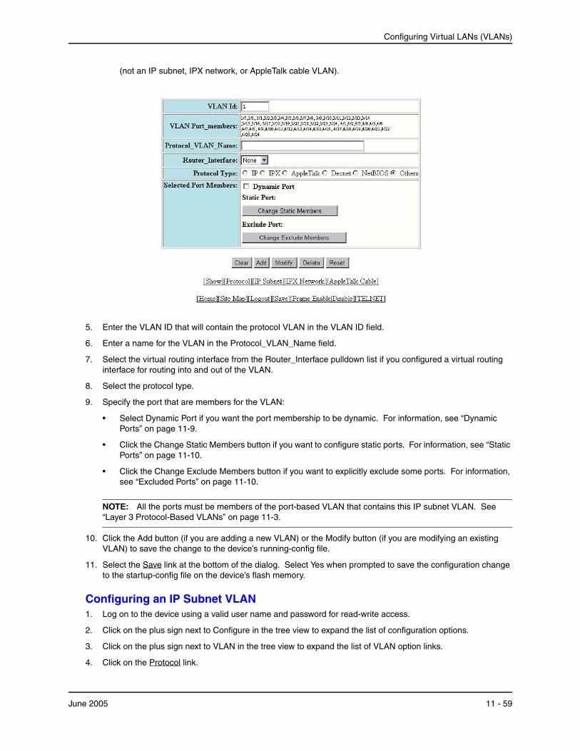
Configuring Virtual LANs (VLANs)
(not an IP subnet, IPX network, or AppleTalk cable VLAN).
5. Enter the VLAN ID that will contain the protocol VLAN in the VLAN ID field.
6. Enter a name for the VLAN in the Protocol_VLAN_Name field.
7. Select the virtual routing interface from the Router_Interface pulldown list if you configured a virtual routing interface for routing into and out of the VLAN.
8. Select the protocol type.
9. Specify the port that are members for the VLAN:
• Select Dynamic Port if you want the port membership to be dynamic. For information, see “Dynamic Ports” on page 11-9.
• Click the Change Static Members button if you want to configure static ports. For information, see “Static Ports” on page 11-10.
• Click the Change Exclude Members button if you want to explicitly exclude some ports. For information, see “Excluded Ports” on page 11-10.
NOTE: All the ports must be members of the port-based VLAN that contains this IP subnet VLAN. See “Layer 3 Protocol-Based VLANs” on page 11-3.
10. Click the Add button (if you are adding a new VLAN) or the Modify button (if you are modifying an existing VLAN) to save the change to the device’s running-config file.
11. Select the Save link at the bottom of the dialog. Select Yes when prompted to save the configuration change to the startup-config file on the device’s flash memory.
Configuring an IP Subnet VLAN1. Log on to the device using a valid user name and password for read-write access.
2. Click on the plus sign next to Configure in the tree view to expand the list of configuration options.
3. Click on the plus sign next to VLAN in the tree view to expand the list of VLAN option links.
4. Click on the Protocol link.
June 2005 11 - 59
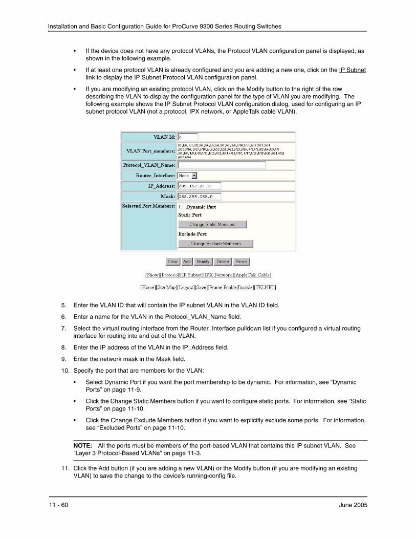
Installation and Basic Configuration Guide for ProCurve 9300 Series Routing Switches
• If the device does not have any protocol VLANs, the Protocol VLAN configuration panel is displayed, as shown in the following example.
• If at least one protocol VLAN is already configured and you are adding a new one, click on the IP Subnet link to display the IP Subnet Protocol VLAN configuration panel.
• If you are modifying an existing protocol VLAN, click on the Modify button to the right of the row describing the VLAN to display the configuration panel for the type of VLAN you are modifying. The following example shows the IP Subnet Protocol VLAN configuration dialog, used for configuring an IP subnet protocol VLAN (not a protocol, IPX network, or AppleTalk cable VLAN).
5. Enter the VLAN ID that will contain the IP subnet VLAN in the VLAN ID field.
6. Enter a name for the VLAN in the Protocol_VLAN_Name field.
7. Select the virtual routing interface from the Router_Interface pulldown list if you configured a virtual routing interface for routing into and out of the VLAN.
8. Enter the IP address of the VLAN in the IP_Address field.
9. Enter the network mask in the Mask field.
10. Specify the port that are members for the VLAN:
• Select Dynamic Port if you want the port membership to be dynamic. For information, see “Dynamic Ports” on page 11-9.
• Click the Change Static Members button if you want to configure static ports. For information, see “Static Ports” on page 11-10.
• Click the Change Exclude Members button if you want to explicitly exclude some ports. For information, see “Excluded Ports” on page 11-10.
NOTE: All the ports must be members of the port-based VLAN that contains this IP subnet VLAN. See “Layer 3 Protocol-Based VLANs” on page 11-3.
11. Click the Add button (if you are adding a new VLAN) or the Modify button (if you are modifying an existing VLAN) to save the change to the device’s running-config file.
11 - 60 June 2005
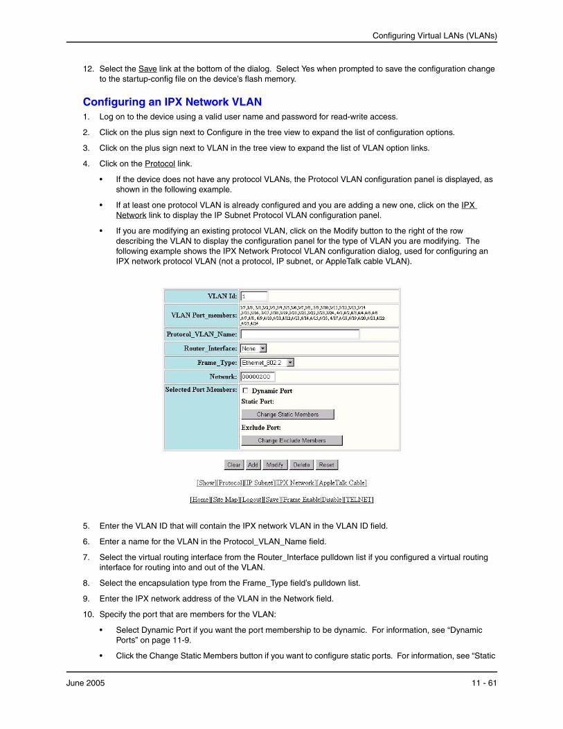
Configuring Virtual LANs (VLANs)
12. Select the Save link at the bottom of the dialog. Select Yes when prompted to save the configuration change to the startup-config file on the device’s flash memory.
Configuring an IPX Network VLAN1. Log on to the device using a valid user name and password for read-write access.
2. Click on the plus sign next to Configure in the tree view to expand the list of configuration options.
3. Click on the plus sign next to VLAN in the tree view to expand the list of VLAN option links.
4. Click on the Protocol link.
• If the device does not have any protocol VLANs, the Protocol VLAN configuration panel is displayed, as shown in the following example.
• If at least one protocol VLAN is already configured and you are adding a new one, click on the IPX Network link to display the IP Subnet Protocol VLAN configuration panel.
• If you are modifying an existing protocol VLAN, click on the Modify button to the right of the row describing the VLAN to display the configuration panel for the type of VLAN you are modifying. The following example shows the IPX Network Protocol VLAN configuration dialog, used for configuring an IPX network protocol VLAN (not a protocol, IP subnet, or AppleTalk cable VLAN).
5. Enter the VLAN ID that will contain the IPX network VLAN in the VLAN ID field.
6. Enter a name for the VLAN in the Protocol_VLAN_Name field.
7. Select the virtual routing interface from the Router_Interface pulldown list if you configured a virtual routing interface for routing into and out of the VLAN.
8. Select the encapsulation type from the Frame_Type field’s pulldown list.
9. Enter the IPX network address of the VLAN in the Network field.
10. Specify the port that are members for the VLAN:
• Select Dynamic Port if you want the port membership to be dynamic. For information, see “Dynamic Ports” on page 11-9.
• Click the Change Static Members button if you want to configure static ports. For information, see “Static
June 2005 11 - 61
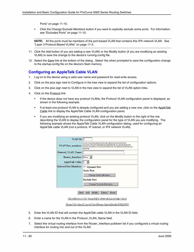
Installation and Basic Configuration Guide for ProCurve 9300 Series Routing Switches
Ports” on page 11-10.
• Click the Change Exclude Members button if you want to explicitly exclude some ports. For information, see “Excluded Ports” on page 11-10.
NOTE: All the ports must be members of the port-based VLAN that contains this IPX network VLAN. See “Layer 3 Protocol-Based VLANs” on page 11-3.
11. Click the Add button (if you are adding a new VLAN) or the Modify button (if you are modifying an existing VLAN) to save the change to the device’s running-config file.
12. Select the Save link at the bottom of the dialog. Select Yes when prompted to save the configuration change to the startup-config file on the device’s flash memory.
Configuring an AppleTalk Cable VLAN1. Log on to the device using a valid user name and password for read-write access.
2. Click on the plus sign next to Configure in the tree view to expand the list of configuration options.
3. Click on the plus sign next to VLAN in the tree view to expand the list of VLAN option links.
4. Click on the Protocol link.
• If the device does not have any protocol VLANs, the Protocol VLAN configuration panel is displayed, as shown in the following example.
• If at least one protocol VLAN is already configured and you are adding a new one, click on the AppleTalk Cable link to display the AppleTalk Cable VLAN configuration panel.
• If you are modifying an existing protocol VLAN, click on the Modify button to the right of the row describing the VLAN to display the configuration panel for the type of VLAN you are modifying. The following example shows the AppleTalk Cable VLAN configuration dialog, used for configuring an AppleTalk cable VLAN (not a protocol, IP subnet, or IPX network VLAN).
5. Enter the VLAN ID that will contain the AppleTalk cable VLAN in the VLAN ID field.
6. Enter a name for the VLAN in the Protocol_VLAN_Name field.
7. Select the virtual routing interface from the Router_Interface pulldown list if you configured a virtual routing interface for routing into and out of the VLAN.
11 - 62 June 2005

Configuring Virtual LANs (VLANs)
8. Select the AppleTalk cable ID from the AppleTalk Cable field’s pulldown list.
9. Specify the port that are members for the VLAN:
• Select Dynamic Port if you want the port membership to be dynamic. For information, see “Dynamic Ports” on page 11-9.
• Click the Change Static Members button if you want to configure static ports. For information, see “Static Ports” on page 11-10.
• Click the Change Exclude Members button if you want to explicitly exclude some ports. For information, see “Excluded Ports” on page 11-10.
NOTE: All the ports must be members of the port-based VLAN that contains this AppleTalk cable VLAN. See “Layer 3 Protocol-Based VLANs” on page 11-3.
10. Click the Add button (if you are adding a new VLAN) or the Modify button (if you are modifying an existing VLAN) to save the change to the device’s running-config file.
11. Select the Save link at the bottom of the dialog. Select Yes when prompted to save the configuration change to the startup-config file on the device’s flash memory.
Displaying VLAN InformationAfter you configure the VLANs, you can verify the configuration using the following methods.
NOTE: If a VLAN name begins with “GVRP_VLAN_“, the VLAN was created by the GARP VLAN Registration Protocol (GVRP). If a VLAN name begins with “STATIC_VLAN_“, the VLAN was created by GVRP and then was converted into a statically configured VLAN.
Displaying System-Wide VLAN InformationUse one of the following methods to display VLAN information for all the VLANs configured on the device.
June 2005 11 - 63

Installation and Basic Configuration Guide for ProCurve 9300 Series Routing Switches
USING THE CLI
Enter the following command at any CLI level. This example shows the display for the IP subnet and IPX network VLANs configured in the examples in “Configuring an IP Subnet VLAN with Dynamic Ports” on page 11-32 and “Configuring an IPX Network VLAN with Dynamic Ports” on page 11-32.
ProCurveRS(config)# show vlans
Total PORT-VLAN entries: 2 Maximum PORT-VLAN entries: 8 legend: [S=Slot] PORT-VLAN 1, Name DEFAULT-VLAN, Priority level0, Spanning tree Off Untagged Ports: (S2) 1 2 3 4 5 6 7 8 9 10 11 12 13 14 15 16 Untagged Ports: (S2) 17 18 19 20 21 22 23 24 Untagged Ports: (S4) 1 2 3 4 5 6 7 8 9 10 11 12 13 14 15 16 Untagged Ports: (S4) 17 18 19 20 21 22 23 24 Tagged Ports: None PORT-VLAN 10, Name IP_VLAN, Priority level0, Spanning tree Off Untagged Ports: (S1) 1 2 3 4 5 6 Tagged Ports: None IP-subnet VLAN 1.1.1.0 255.255.255.0, Dynamic port enabled Name: Mktg-LAN Static ports: None Exclude ports: None Dynamic ports: (S1) 1 2 3 4 5 6 PORT-VLAN 20, Name IPX_VLAN, Priority level0, Spanning tree Off Untagged Ports: (S2) 1 2 3 4 5 6 Tagged Ports: None IPX-network VLAN 0000ABCD, frame type ethernet_ii, Dynamic port enabled Name: Eng-LAN Static ports: None Exclude ports: None Dynamic ports: (S2) 1 2 3 4 5 6
Syntax: show vlans [<vlan-id> | ethernet <portnum>]
The <vlan-id> parameter specifies a VLAN for which you want to display the configuration information.
The ethernet <portnum> parameter specifies a port. If you use this parameter, the command lists all the VLAN memberships for the port.
USING THE WEB MANAGEMENT INTERFACE
To display VLAN configuration information:
1. Log on to the device using a valid user name and password for read-only or read-write access. The System configuration dialog is displayed.
2. Click on the plus sign next to Configure in the tree view to expand the list of configuration options.
3. Click on the plus sign next to VLAN in the tree view to expand the list of VLAN option links.
4. Click on the Port link to display the Port-based VLAN table or the Protocol link to display the Protocol-based VLAN table.
Displaying VLAN Information for Specific PortsUse one of the following methods to display VLAN information for specific ports.
11 - 64 June 2005

Configuring Virtual LANs (VLANs)
USING THE CLI
To display VLAN information for all the VLANs of which port 7/1 is a member, enter the following command:
ProCurveRS(config)# show vlans e 7/1
Total PORT-VLAN entries: 3 Maximum PORT-VLAN entries: 8 legend: [S=Slot] PORT-VLAN 100, Name [None], Priority level0, Spanning tree Off Untagged Ports: (S7) 1 2 3 4 Tagged Ports: None IP-subnet VLAN 207.95.11.0 255.255.255.0, Dynamic port disabled Static ports: (S7) 1 2 Exclude ports: None Dynamic ports: None
Syntax: show vlans [<vlan-id> | ethernet <portnum>]
The <vlan-id> parameter specifies a VLAN for which you want to display the configuration information.
The ethernet <portnum> parameter specifies a port. If you use this parameter, the command lists all the VLAN memberships for the port.
USING THE WEB MANAGEMENT INTERFACE
You cannot display port-specific VLAN information using the Web management interface.
June 2005 11 - 65

Installation and Basic Configuration Guide for ProCurve 9300 Series Routing Switches
11 - 66 June 2005
Chapter 12Configuring IP Multicast Traffic Reduction
ProCurve Routing Switches forward all IP multicast traffic by default based on the Layer 2 information in the packets. Optionally, you can enable these HP devices to make forwarding decisions in hardware, based on multicast group by enabling the IP Multicast Traffic Reduction feature.
When this feature is enabled, these HP devices examine the MAC address in an IP multicast packet and forward the packet only on the ports from which the device has received Group Membership reports for that group, instead of forwarding all multicast traffic to all ports. The device sends traffic for other groups out all ports.
When you enable IP Multicast Traffic Reduction, you also can configure the following features:
• IGMP mode – When you enable IP Multicast Traffic Reduction, the device passively listens for IGMP Group Membership reports by default. If the multicast domain does not have a Routing Switch to send IGMP queries to elicit these Group Membership reports, you can enable the device to actively send the IGMP queries.
• Query interval – The query interval specifies how often the device sends Group Membership queries. This query interval applies only to the active IGMP mode. The default is 60 seconds. You can change the interval to a value from 10 – 600 seconds.
• Age interval – The age interval specifies how long an IGMP group can remain in the IGMP group table without the device receiving a Group Membership report for the group. If the age interval expires before the device receives another Group Membership report for the group, the device removes the entry from the table. The default is 140 seconds. You can change the interval to a value from 10 – 1220 seconds.
• Forwarding policy – The device forwards all IP multicast traffic by default but you can enable the device to forward IP multicast traffic only for groups for which the device has received a Group Membership report, and drop traffic for all other groups.
The following sections describe how to configure IP multicast traffic reduction and PIM SM Traffic Snooping parameters on an HP device.
NOTE: Beginning with software release 07.7.00, IP multicast traffic reduction and PIM SM Traffic Snooping is available on Routing Switches.
Enabling IP Multicast Traffic ReductionBy default, HP devices forward all IP multicast traffic out all ports except the port on which the traffic was received. To reduce multicast traffic through the device, you can enable IP Multicast Traffic Reduction. This feature configures the device to forward multicast traffic only on the ports attached to multicast group members, instead of forwarding all multicast traffic to all ports. The device determines the ports that are attached to multicast group
June 2005 12 - 1
Installation and Basic Configuration Guide for ProCurve 9300 Series Routing Switches
members based on entries in the IGMP table. Each entry in the table consists of MAC addresses and the HP device ports from which the device has received Group Membership reports for that group.
By default, the device broadcasts traffic addressed to an IP multicast group that doesn’t have any entries in the IGMP table. When you enable IP Multicast Traffic Reduction, the device determines the ports that are attached to multicast group members based on entries in the IGMP table. The IGMP table entries are created when the VLAN receives a group membership report for a group. Each entry in the table consists of an IP multicast group address and the HP device ports from which the device has received Group Membership reports.
When the device receives traffic for an IP multicast group, the device looks in the IGMP table for an entry corresponding to that group. If the device finds an entry, the device forwards the group traffic out the ports listed in the corresponding entries, as long as the ports are members of the same VLAN. If the table does not contain an entry corresponding to the group or if the port is a member of the default VLAN, the device broadcasts the traffic.
NOTE: When one or more HP devices are running Layer 2 IP Multicast Traffic reduction, configure one of the devices for active IGMP and leave the other devices configured for passive IGMP. However, if the IP multicast domain contains a multicast-capable Routing Switch, configure all the HP devices for passive IGMP and allow the Routing Switch to actively send the IGMP queries.
To enable IP Multicast Traffic Reduction, use either of the following methods.
USING THE CLI
To enable IP Multicast Traffic Reduction, enter the following command:
ProCurveRS(config)# ip multicast
Syntax: [no] ip multicast
NOTE: If the "route-only" feature is enabled on the Routing Switch, then IP Multicast Traffic Reduction will not be supported.
NOTE: This feature is not supported on the default VLAN of Routing Switches.
To verify that IP Multicast Traffic Reduction is enabled, enter the following command at any level of the CLI:
ProCurveRS(config)# show ip multicast IP multicast is enabled - Active
Syntax: show ip multicast
USING THE WEB MANAGEMENT INTERFACE
To enable IP Multicast Traffic Reduction on a device:
NOTE: This feature is not available on Routing Switches.
1. Log on to the device using a valid user name and password for read-write access. The System configuration panel is displayed.
2. Select Enable next to IP Multicast.
3. Click the Apply button to save the change to the device’s running-config file.
4. Select the Save link at the bottom of the dialog, then select Yes when prompted to save the configuration change to the startup-config file on the device’s flash memory.
Changing the IGMP ModeWhen you enable IP Multicast Traffic Reduction on the device, IGMP also is enabled. The device uses IGMP to maintain a table of the Group Membership reports received by the device. You can use active or passive IGMP mode. The default mode is passive.
• Active – When active IGMP mode is enabled, an HP device actively sends out IGMP queries to identify IP
12 - 2 June 2005
Configuring IP Multicast Traffic Reduction
multicast groups on the network and makes entries in the IGMP table based on the Group Membership reports received from the network.
NOTE: Routing Switches in the network generally handle this operation. Use the active IGMP mode only when the device is in a stand-alone network with no external IP multicast Routing Switch attachments. In this case, enable the active IGMP mode on only one of the devices and leave the other devices configured for passive IGMP mode.
• Passive – When passive IGMP mode is enabled, the device listens for IGMP Group Membership reports but does not send IGMP queries. The passive mode is sometimes called “IGMP snooping”. Use this mode when another device in the network is actively sending queries.
To set change the IGMP mode, use either of the following methods.
USING THE CLI
To enable active IGMP, enter the following command:
ProCurveRS(config)# ip multicast active ProCurveRS(config)# write memory ProCurveRS(config)# end ProCurveRS# reload
Syntax: [no] ip multicast active | passive
To enable passive IGMP, enter the following command:
ProCurveRS(config)# ip multicast passive ProCurveRS(config)# write memory ProCurveRS(config)# end ProCurveRS# reload
USING THE WEB MANAGEMENT INTERFACE
To change the IGMP mode:
NOTE: This feature is not available on Routing Switches.
1. Log on to the device using a valid user name and password for read-write access. The System configuration panel is displayed.
2. Select Active or Passive next to IGMP.
3. Click the Apply button to save the change to the device’s running-config file.
4. Select the Save link at the bottom of the dialog, then select Yes when prompted to save the configuration change to the startup-config file on the device’s flash memory.
Disabling IGMP on Individual Ports
NOTE: IP Multicast Traffic Reduction cannot be disabled on individual ports of a Routing Switch. You cannot use the ip-multicast-disable command that is available . IP multicast must be enabled and disabled globally on Routing Switches.
By default, when you enable IP multicast on an HP device, all ports on the device are configured for IGMP. If you are using active IGMP, all ports can send IGMP queries and receive IGMP reports. If you are using passive IGMP, all ports can receive IGMP queries.
You can disable IGMP on individual ports if you want to block all IP multicast traffic on those ports. When you disable IGMP on an individual port, the device does not forward any multicast traffic out the port, but other ports can still send and receive multicast traffic.
To disable IGMP on a port, use the following CLI method.
June 2005 12 - 3
Installation and Basic Configuration Guide for ProCurve 9300 Series Routing Switches
USING THE CLI
ProCurveRS(config)# int e 1/5 ProCurveRS(config-if-1/5)# ip-multicast-disable
Syntax: [no] ip-multicast-disable
The command in this example disables IGMP on port 1/5 but does not affect the state of IGMP on other ports.
USING THE WEB MANAGEMENT INTERFACE
You cannot disable IGMP on a port using the Web management interface.
Modifying the Query IntervalIf IP Multicast Traffic Reduction is set to active mode, you can modify the query interval, which specifies how often an HP device enabled for active IP Multicast Traffic Reduction sends Group Membership queries.
NOTE: The query interval applies only to the active mode of IP Multicast Traffic reduction.
To modify the query interval, use the following CLI method.
USING THE CLI
To modify the query interval, enter a command such as the following:
ProCurveRS(config)# ip multicast query-interval 120
Syntax: [no] ip multicast query-interval <interval>
The <interval> parameter specifies the interval between queries. You can specify a value from 10 – 600 seconds. The default is 60 seconds.
USING THE WEB MANAGEMENT INTERFACE
You cannot configure this feature using the Web management interface.
Modifying the Age IntervalWhen the device receives a Group Membership report, the device makes an entry in the IGMP group table for the group in the report. The age interval specifies how long the entry can remain in the table without the device receiving another Group Membership report.
To modify the age interval, use the following CLI method.
USING THE CLI
To modify the age interval, enter a command such as the following:
ProCurveRS(config)# ip multicast age-interval 280
Syntax: [no] ip multicast age-interval <interval>
The <interval> parameter specifies the interval between queries. You can specify a value from 10 – 1220 seconds. The default is 140 seconds.
USING THE WEB MANAGEMENT INTERFACE
You cannot configure this feature using the Web management interface.
Filtering Multicast GroupsBy default, HP devices forward multicast traffic for all valid multicast groups. You can configure an HP device to filter out all multicast traffic for groups other than the ones for which the device has received Group Membership reports.
When device starts up, it forwards all multicast groups even though multicast traffic filters are configured. This process continues until the device receives a group membership report. Once the group membership report is
12 - 4 June 2005
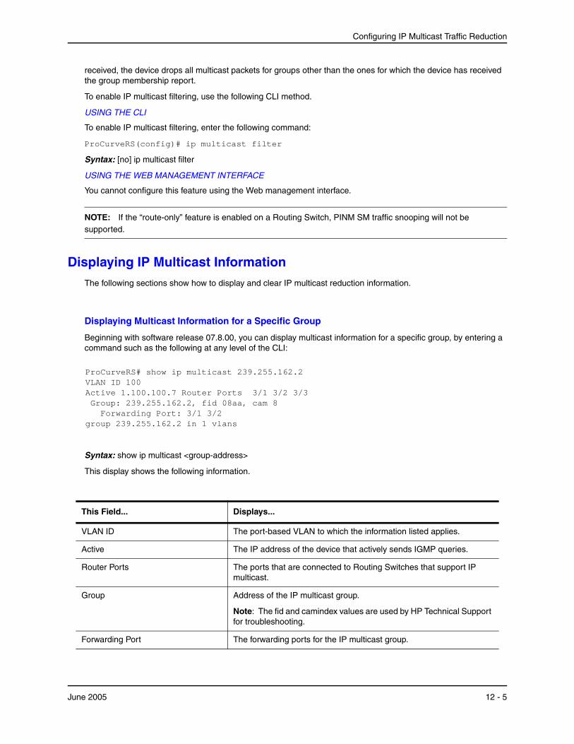
Configuring IP Multicast Traffic Reduction
received, the device drops all multicast packets for groups other than the ones for which the device has received the group membership report.
To enable IP multicast filtering, use the following CLI method.
USING THE CLI
To enable IP multicast filtering, enter the following command:
ProCurveRS(config)# ip multicast filter
Syntax: [no] ip multicast filter
USING THE WEB MANAGEMENT INTERFACE
You cannot configure this feature using the Web management interface.
NOTE: If the “route-only” feature is enabled on a Routing Switch, PINM SM traffic snooping will not be supported.
Displaying IP Multicast InformationThe following sections show how to display and clear IP multicast reduction information.
Displaying Multicast Information for a Specific Group
Beginning with software release 07.8.00, you can display multicast information for a specific group, by entering a command such as the following at any level of the CLI:
ProCurveRS# show ip multicast 239.255.162.2 VLAN ID 100 Active 1.100.100.7 Router Ports 3/1 3/2 3/3 Group: 239.255.162.2, fid 08aa, cam 8 Forwarding Port: 3/1 3/2 group 239.255.162.2 in 1 vlans
Syntax: show ip multicast <group-address>
This display shows the following information.
This Field... Displays...
VLAN ID The port-based VLAN to which the information listed applies.
Active The IP address of the device that actively sends IGMP queries.
Router Ports The ports that are connected to Routing Switches that support IP multicast.
Group Address of the IP multicast group.
Note: The fid and camindex values are used by HP Technical Support for troubleshooting.
Forwarding Port The forwarding ports for the IP multicast group.
June 2005 12 - 5
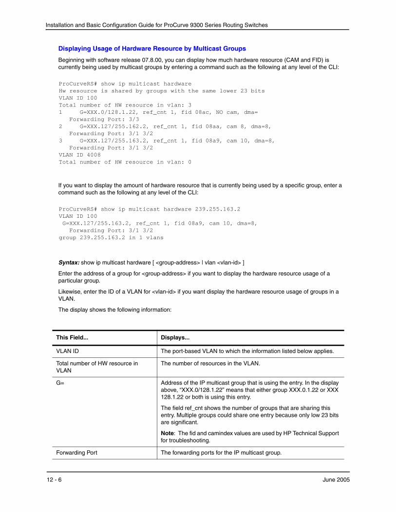
Installation and Basic Configuration Guide for ProCurve 9300 Series Routing Switches
Displaying Usage of Hardware Resource by Multicast Groups
Beginning with software release 07.8.00, you can display how much hardware resource (CAM and FID) is currently being used by multicast groups by entering a command such as the following at any level of the CLI:
ProCurveRS# show ip multicast hardware Hw resource is shared by groups with the same lower 23 bits VLAN ID 100 Total number of HW resource in vlan: 3 1 G=XXX.0/128.1.22, ref_cnt 1, fid 08ac, NO cam, dma= Forwarding Port: 3/3 2 G=XXX.127/255.162.2, ref_cnt 1, fid 08aa, cam 8, dma=8, Forwarding Port: 3/1 3/2 3 G=XXX.127/255.163.2, ref_cnt 1, fid 08a9, cam 10, dma=8, Forwarding Port: 3/1 3/2 VLAN ID 4008 Total number of HW resource in vlan: 0
If you want to display the amount of hardware resource that is currently being used by a specific group, enter a command such as the following at any level of the CLI:
ProCurveRS# show ip multicast hardware 239.255.163.2 VLAN ID 100 G=XXX.127/255.163.2, ref_cnt 1, fid 08a9, cam 10, dma=8, Forwarding Port: 3/1 3/2 group 239.255.163.2 in 1 vlans
Syntax: show ip multicast hardware [ <group-address> | vlan <vlan-id> ]
Enter the address of a group for <group-address> if you want to display the hardware resource usage of a particular group.
Likewise, enter the ID of a VLAN for <vlan-id> if you want display the hardware resource usage of groups in a VLAN.
The display shows the following information:
This Field... Displays...
VLAN ID The port-based VLAN to which the information listed below applies.
Total number of HW resource in VLAN
The number of resources in the VLAN.
G= Address of the IP multicast group that is using the entry. In the display above, “XXX.0/128.1.22” means that either group XXX.0.1.22 or XXX 128.1.22 or both is using this entry.
The field ref_cnt shows the number of groups that are sharing this entry. Multiple groups could share one entry because only low 23 bits are significant.
Note: The fid and camindex values are used by HP Technical Support for troubleshooting.
Forwarding Port The forwarding ports for the IP multicast group.
12 - 6 June 2005

Configuring IP Multicast Traffic Reduction
Displaying Software Resource Usage
Beginning with software release 07.8.00, you can display the amount of software resources used by each IGMP and PIM process that is enabled by entering the following command at any level of the CLI:
ProCurveRS# show ip multicast resource alloc in-use avail allo-fail up-limit size pim neighbor 32 3 29 0 512 19 pim source-hash 256 3 253 0 10000 484 pim source 1024 7 1017 0 400000 6 pim source port 1024 7 1017 0 200000 13 igmp vlan struct 16 2 14 0 255 479 igmp mdb 256 3 253 0 10000 385 igmp hw resource 256 3 253 0 10000 5786 igmp port-age 2048 8 2040 0 100000 8 igmp leave 512 0 512 0 no-limit 8 In use: hw-res: 3, cam: 2, fid: 6 cpu forwarded packets: 411
Syntax: show ip multicast resource
Displaying Multicast Traffic Statistics
The show ip multicast statistics command has been available in previous releases. However, in software release 07.8.00, the report has been updated to show the following message if an IGMP V3 report is received:
*** Warning! IGMPv3 reports: 10
The warning shows the count of IGMP V3 that were received . Refer to the Command Line Interface Reference for ProCurve 9300/9400 Series Routing Switches for information on this command.
Displaying Multicast Information by VLAN
Beginning with software release 07.8.00, you can display multicast information for a specific VLAN by entering command such as the following at any level of the CLI:
ProCurveRS# show ip multicast vlan 100 Only display vlan 100 VLAN ID 100 Querier: 1.100.100.7, (port: 3/1) Router Ports: 3/1 3/2 Total number of Multicast Group in vlan: 3 1 Group: 224.0.1.22, fid 08ac, NO cam Forwarding Port: 3/3 2 Group: 239.255.162.2, fid 08aa, cam 8 Forwarding Port: 3/1 3/2 3 Group: 239.255.163.2, fid 08a9, cam 10 Forwarding Port: 3/1 3/2
Syntax: show ip multicast vlan <vlan-id>
June 2005 12 - 7
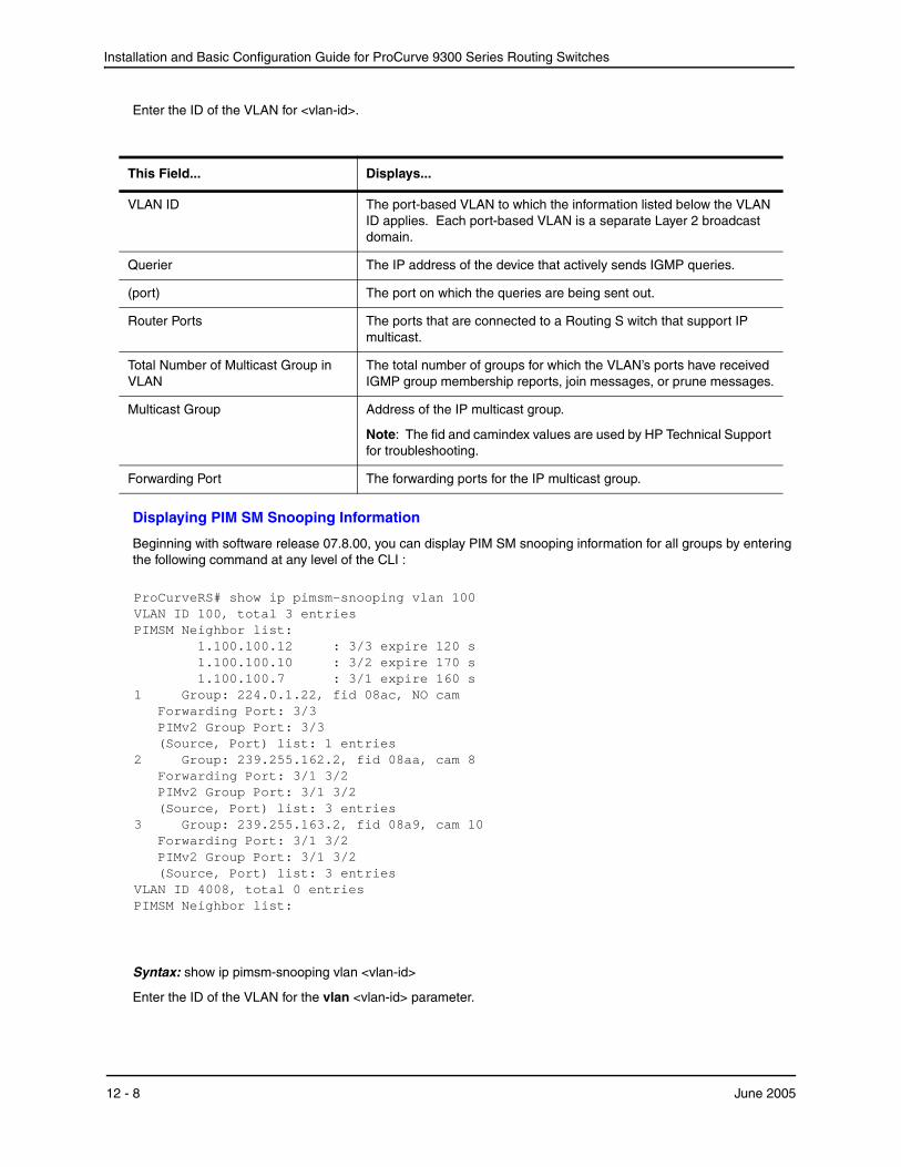
Installation and Basic Configuration Guide for ProCurve 9300 Series Routing Switches
Enter the ID of the VLAN for <vlan-id>.
This Field... Displays...
VLAN ID The port-based VLAN to which the information listed below the VLAN ID applies. Each port-based VLAN is a separate Layer 2 broadcast domain.
Querier The IP address of the device that actively sends IGMP queries.
(port) The port on which the queries are being sent out.
Router Ports The ports that are connected to a Routing S witch that support IP multicast.
Total Number of Multicast Group in VLAN
The total number of groups for which the VLAN’s ports have received IGMP group membership reports, join messages, or prune messages.
Multicast Group Address of the IP multicast group.
Note: The fid and camindex values are used by HP Technical Support for troubleshooting.
Forwarding Port The forwarding ports for the IP multicast group.
Displaying PIM SM Snooping Information
Beginning with software release 07.8.00, you can display PIM SM snooping information for all groups by entering the following command at any level of the CLI :
ProCurveRS# show ip pimsm-snooping vlan 100 VLAN ID 100, total 3 entries PIMSM Neighbor list: 1.100.100.12 : 3/3 expire 120 s 1.100.100.10 : 3/2 expire 170 s 1.100.100.7 : 3/1 expire 160 s 1 Group: 224.0.1.22, fid 08ac, NO cam Forwarding Port: 3/3 PIMv2 Group Port: 3/3 (Source, Port) list: 1 entries 2 Group: 239.255.162.2, fid 08aa, cam 8 Forwarding Port: 3/1 3/2 PIMv2 Group Port: 3/1 3/2 (Source, Port) list: 3 entries 3 Group: 239.255.163.2, fid 08a9, cam 10 Forwarding Port: 3/1 3/2 PIMv2 Group Port: 3/1 3/2 (Source, Port) list: 3 entries VLAN ID 4008, total 0 entries PIMSM Neighbor list:
Syntax: show ip pimsm-snooping vlan <vlan-id>
Enter the ID of the VLAN for the vlan <vlan-id> parameter.
12 - 8 June 2005
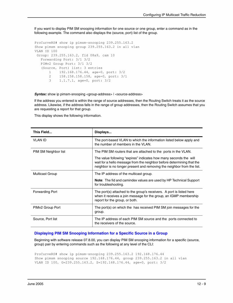
Configuring IP Multicast Traffic Reduction
If you want to display PIM SM snooping information for one source or one group, enter a command as in the following example. The command also displays the (source, port) list of the group.
ProCurveRS# show ip pimsm-snooping 239.255.163.2 Show pimsm snooping group 239.255.163.2 in all vlan VLAN ID 100 Group: 239.255.163.2, fid 08a9, cam 10 Forwarding Port: 3/1 3/2 PIMv2 Group Port: 3/1 3/2 (Source, Port) list: 3 entries 1 192.168.176.44, age=0, port: 3/2 2 158.158.158.158, age=0, port: 3/1 3 1.1.7.1, age=0, port: 3/2
Syntax: show ip pimsm-snooping <group-address> | <source-address>
If the address you entered is within the range of source addresses, then the Routing Switch treats it as the source address. Likewise, if the address falls in the range of group addresses, then the Routing Switch assumes that you are requesting a report for that group.
This display shows the following information.
This Field... Displays...
VLAN ID The port-based VLAN to which the information listed below apply and the number of members in the VLAN.
PIM SM Neighbor list The PIM SM routers that are attached to the ports in the VLAN.
The value following “expires” indicates how many seconds the will wait for a hello message from the neighbor before determining that the neighbor is no longer present and removing the neighbor from the list.
Multicast Group The IP address of the multicast group.
Note: The fid and camindex values are used by HP Technical Support for troubleshooting.
Forwarding Port The port(s) attached to the group’s receivers. A port is listed here when it receives a join message for the group, an IGMP membership report for the group, or both.
PIMv2 Group Port The port(s) on which the has received PIM SM join messages for the group.
Source, Port list The IP address of each PIM SM source and the ports connected to the receivers of the source.
Displaying PIM SM Snooping Information for a Specific Source in a Group
Beginning with software release 07.8.00, you can display PIM SM snooping information for a specific (source, group) pair by entering commands such as the following at any level of the CLI:
ProCurveRS# show ip pimsm-snooping 239.255.163.2 192.168.176.44 Show pimsm snooping source 192.168.176.44, group 239.255.163.2 in all vlan VLAN ID 100, G=239.255.163.2, S=192.168.176.44, age=0, port: 3/2
June 2005 12 - 9
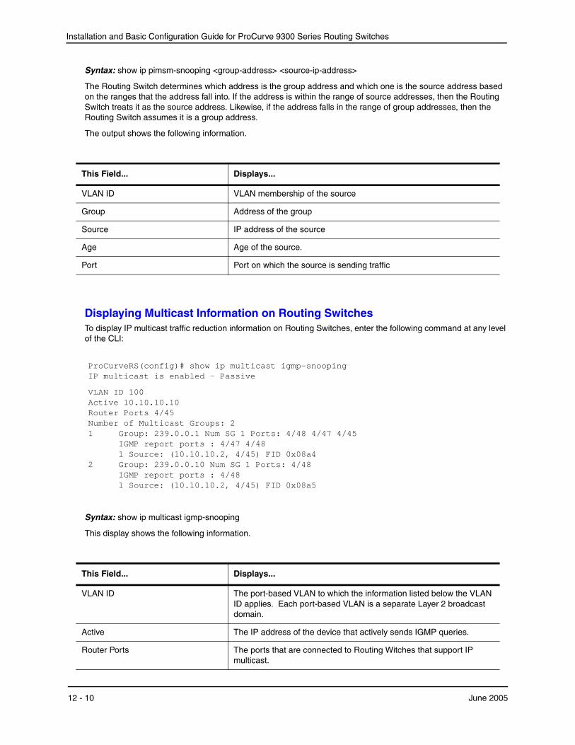
Installation and Basic Configuration Guide for ProCurve 9300 Series Routing Switches
Syntax: show ip pimsm-snooping <group-address> <source-ip-address>
The Routing Switch determines which address is the group address and which one is the source address based on the ranges that the address fall into. If the address is within the range of source addresses, then the Routing Switch treats it as the source address. Likewise, if the address falls in the range of group addresses, then the Routing Switch assumes it is a group address.
The output shows the following information.
This Field... Displays...
VLAN ID VLAN membership of the source
Group Address of the group
Source IP address of the source
Age Age of the source.
Port Port on which the source is sending traffic
Displaying Multicast Information on Routing SwitchesTo display IP multicast traffic reduction information on Routing Switches, enter the following command at any level of the CLI:
ProCurveRS(config)# show ip multicast igmp-snooping IP multicast is enabled - Passive
VLAN ID 100 Active 10.10.10.10 Router Ports 4/45 Number of Multicast Groups: 2 1 Group: 239.0.0.1 Num SG 1 Ports: 4/48 4/47 4/45 IGMP report ports : 4/47 4/48 1 Source: (10.10.10.2, 4/45) FID 0x08a4 2 Group: 239.0.0.10 Num SG 1 Ports: 4/48 IGMP report ports : 4/48 1 Source: (10.10.10.2, 4/45) FID 0x08a5
Syntax: show ip multicast igmp-snooping
This display shows the following information.
This Field... Displays...
VLAN ID The port-based VLAN to which the information listed below the VLAN ID applies. Each port-based VLAN is a separate Layer 2 broadcast domain.
Active The IP address of the device that actively sends IGMP queries.
Router Ports The ports that are connected to Routing Witches that support IP multicast.
12 - 10 June 2005
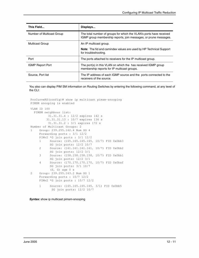
Configuring IP Multicast Traffic Reduction
You also can display PIM SM information on Routing Switches by entering the following command, at any level of the CLI:
ProCurveRS(config)# show ip multicast pimsm-snooping PIMSM snooping is enabled
VLAN ID 100 PIMSM neighbour list: 31.31.31.4 : 12/2 expires 142 s 31.31.31.13 : 10/7 expires 136 s 31.31.31.2 : 3/1 expires 172 s Number of Multicast Groups: 2 1 Group: 239.255.162.4 Num SG 4 Forwarding ports : 3/1 12/2 PIMv2 *G join ports : 3/1 12/2 1 Source: (165.165.165.165, 10/7) FID 0x0bb3 SG join ports: 12/2 10/7 2 Source: (161.161.161.161, 10/7) FID 0x0bb2 SG join ports: 12/2 3/1 3 Source: (158.158.158.158, 10/7) FID 0x0bb1 SG join ports: 12/2 3/1 4 Source: (170.170.170.170, 10/7) FID 0x0baf SG join ports: 3/1 10/7 (S, G) age 0 s 2 Group: 239.255.163.2 Num SG 1 Forwarding ports : 10/7 12/2 PIMv2 *G join ports : 10/7 12/2
1 Source: (165.165.165.165, 3/1) FID 0x0bb5 SG join ports: 12/2 10/7
Syntax: show ip multicast pimsm-snooping
Number of Multicast Group The total number of groups for which the VLAN’s ports have received IGMP group membership reports, join messages, or prune messages.
Multicast Group An IP multicast group.
Note: The fid and camindex values are used by HP Technical Support for troubleshooting.
Port The ports attached to receivers for the IP multicast group.
IGMP Report Port The port(s) in this VLAN on which the has received IGMP group membership reports for IP multicast groups.
Source, Port list The IP address of each IGMP source and the ports connected to the receivers of the source.
This Field... Displays...
June 2005 12 - 11
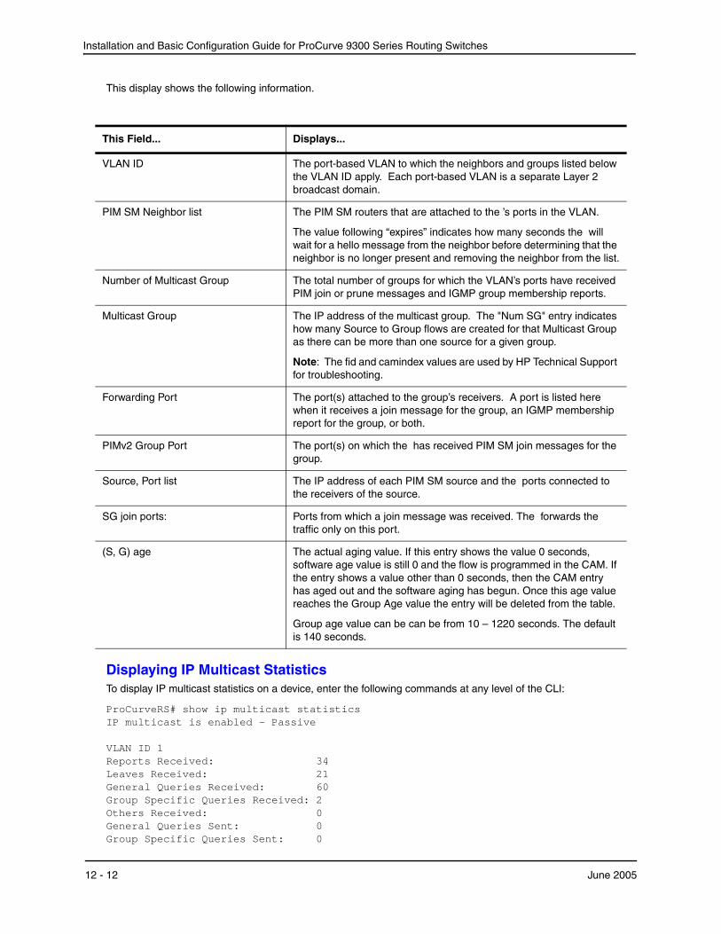
Installation and Basic Configuration Guide for ProCurve 9300 Series Routing Switches
This display shows the following information.
This Field... Displays...
VLAN ID The port-based VLAN to which the neighbors and groups listed below the VLAN ID apply. Each port-based VLAN is a separate Layer 2 broadcast domain.
PIM SM Neighbor list The PIM SM routers that are attached to the ’s ports in the VLAN.
The value following “expires” indicates how many seconds the will wait for a hello message from the neighbor before determining that the neighbor is no longer present and removing the neighbor from the list.
Number of Multicast Group The total number of groups for which the VLAN’s ports have received PIM join or prune messages and IGMP group membership reports.
Multicast Group The IP address of the multicast group. The "Num SG" entry indicates how many Source to Group flows are created for that Multicast Group as there can be more than one source for a given group.
Note: The fid and camindex values are used by HP Technical Support for troubleshooting.
Forwarding Port The port(s) attached to the group’s receivers. A port is listed here when it receives a join message for the group, an IGMP membership report for the group, or both.
PIMv2 Group Port The port(s) on which the has received PIM SM join messages for the group.
Source, Port list The IP address of each PIM SM source and the ports connected to the receivers of the source.
SG join ports: Ports from which a join message was received. The forwards the traffic only on this port.
(S, G) age The actual aging value. If this entry shows the value 0 seconds, software age value is still 0 and the flow is programmed in the CAM. If the entry shows a value other than 0 seconds, then the CAM entry has aged out and the software aging has begun. Once this age value reaches the Group Age value the entry will be deleted from the table.
Group age value can be can be from 10 – 1220 seconds. The default is 140 seconds.
Displaying IP Multicast StatisticsTo display IP multicast statistics on a device, enter the following commands at any level of the CLI:
ProCurveRS# show ip multicast statistics IP multicast is enabled - Passive VLAN ID 1 Reports Received: 34 Leaves Received: 21 General Queries Received: 60 Group Specific Queries Received: 2 Others Received: 0 General Queries Sent: 0 Group Specific Queries Sent: 0
12 - 12 June 2005
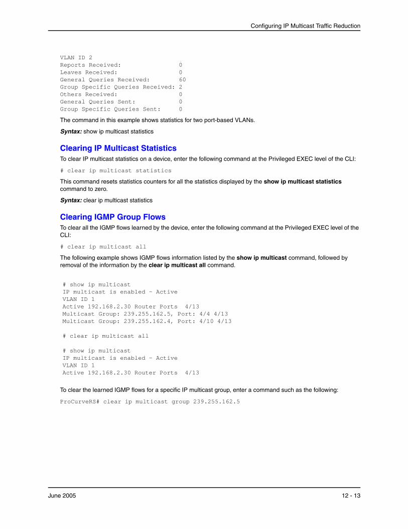
Configuring IP Multicast Traffic Reduction
VLAN ID 2 Reports Received: 0 Leaves Received: 0 General Queries Received: 60 Group Specific Queries Received: 2 Others Received: 0 General Queries Sent: 0 Group Specific Queries Sent: 0
The command in this example shows statistics for two port-based VLANs.
Syntax: show ip multicast statistics
Clearing IP Multicast StatisticsTo clear IP multicast statistics on a device, enter the following command at the Privileged EXEC level of the CLI:
# clear ip multicast statistics
This command resets statistics counters for all the statistics displayed by the show ip multicast statistics command to zero.
Syntax: clear ip multicast statistics
Clearing IGMP Group FlowsTo clear all the IGMP flows learned by the device, enter the following command at the Privileged EXEC level of the CLI:
# clear ip multicast all
The following example shows IGMP flows information listed by the show ip multicast command, followed by removal of the information by the clear ip multicast all command.
# show ip multicast IP multicast is enabled - Active VLAN ID 1 Active 192.168.2.30 Router Ports 4/13 Multicast Group: 239.255.162.5, Port: 4/4 4/13 Multicast Group: 239.255.162.4, Port: 4/10 4/13 # clear ip multicast all # show ip multicast IP multicast is enabled - Active VLAN ID 1 Active 192.168.2.30 Router Ports 4/13
To clear the learned IGMP flows for a specific IP multicast group, enter a command such as the following:
ProCurveRS# clear ip multicast group 239.255.162.5
June 2005 12 - 13

Installation and Basic Configuration Guide for ProCurve 9300 Series Routing Switches
The following example shows how to clear the IGMP flows for a specific group and retain reports for other groups.
ProCurveRS# show ip multicast IP multicast is enabled - Active VLAN ID 1 Active 192.168.2.30 Router Ports 4/13 Multicast Group: 239.255.162.5, Port: 4/4 4/13 Multicast Group: 239.255.162.4, Port: 4/10 4/13 ProCurveRS# clear ip multicast group 239.255.162.5 ProCurveRS# show ip multicast IP multicast is enabled - Active VLAN ID 1 Active 192.168.2.30 Router Ports 4/13 Multicast Group: 239.255.162.4, Port: 4/10 4/13
Syntax: clear ip multicast all | group <group-id>
The all parameter clears the learned flows for all groups.
The group <group-id> parameter clears the flows for the specified group but does not clear the flows for other groups.
12 - 14 June 2005
Chapter 13Configuring
GARP VLAN Registration Protocol (GVRP)
GARP VLAN Registration Protocol (GVRP) is a Generic Attribute Registration Protocol (GARP) application that provides VLAN registration service by means of dynamic configuration (registration) and distribution of VLAN membership information.
An HP device enabled for GVRP can do the following:
• Learn about VLANs from other HP devices and configure those VLANs on the ports that learn about the VLANs. The device listens for GVRP Protocol Data Units (PDUs) from other devices, and implements the VLAN configuration information in the PDUs.
• Advertise VLANs configured on the device to other HP devices. The device sends GVRP PDUs advertising its VLANs to other devices. GVRP advertises statically configured VLANs and VLANs learned from other devices through GVRP.
GVRP enables an HP device to dynamically create 802.1Q-compliant VLANs on links with other devices that are running GVRP. GVRP reduces the chances for errors in VLAN configuration by automatically providing VLAN ID consistency across the network. You can use GVRP to propagate VLANs to other GVRP-aware devices automatically, without the need to manually configure the VLANs on each device. In addition, if the VLAN configuration on a device changes, GVRP automatically changes the VLAN configurations of the affected devices.
The HP implementation of GARP and GVRP is based on the following standards:
• ANSI/IEEE standard 802.1D, 1998 edition
• IEEE standard 802.1Q, 1998 edition; approved December 8, 1998
• IEEE draft P802.1w/D10, March 26, 2001
• IEEE draft P802.1u/D9, November 23, 2000
• IEEE draft P802.1t/D10, November 20, 2000
Application ExamplesFigure 13.1 shows an example of a network that uses GVRP. This section describes various ways you can use GVRP in a network such as this one. “CLI Examples” on page 13-17 lists the CLI commands to implement the applications of GVRP described in this section.
June 2005 13 - 1
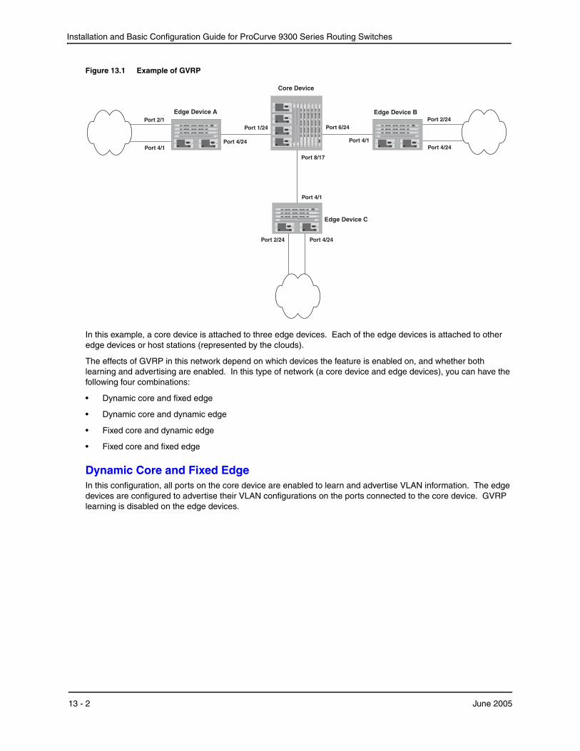
Installation and Basic Configuration Guide for ProCurve 9300 Series Routing Switches
Figure 13.1 Example of GVRP
Edge Device C
Core Device
Port 4/24
Edge Device BEdge Device A
Port 4/1Port 4/24
Port 2/24
Port 1/24
Port 4/1
Port 4/1
Port 2/1Port 6/24
Port 8/17
Port 2/24
Port 4/24
In this example, a core device is attached to three edge devices. Each of the edge devices is attached to other edge devices or host stations (represented by the clouds).
The effects of GVRP in this network depend on which devices the feature is enabled on, and whether both learning and advertising are enabled. In this type of network (a core device and edge devices), you can have the following four combinations:
• Dynamic core and fixed edge
• Dynamic core and dynamic edge
• Fixed core and dynamic edge
• Fixed core and fixed edge
Dynamic Core and Fixed EdgeIn this configuration, all ports on the core device are enabled to learn and advertise VLAN information. The edge devices are configured to advertise their VLAN configurations on the ports connected to the core device. GVRP learning is disabled on the edge devices.
13 - 2 June 2005

Configuring GARP VLAN Registration Protocol (GVRP)
Core Device Edge Device A Edge Device B Edge Device C
GVRP is enabled on all ports.
Both learning and advertising are enabled.
Note: Since learning is disabled on all the edge devices, advertising on the core device has no effect in this configuration.
GVRP is enabled on port 4/24. Learning is disabled.
VLAN 20
Port 2/1 (untagged)
Port 4/24 (tagged)
VLAN 40
Port 4/1 (untagged)
Port 4/24 (tagged)
GVRP is enabled on port 4/1. Learning is disabled.
VLAN 20
Port 2/24 (untagged)
Port 4/1 (tagged)
VLAN 30
Port 4/24 (untagged)
Port 4/1 (tagged)
GVRP is enabled on port 4/1. Learning is disabled.
VLAN 30
Port 2/24 (untagged)
Port 4/1 (tagged)
VLAN 40
Port 4/24 (untagged)
Port 4/1 (tagged)
In this configuration, the edge devices are statically (manually) configured with VLAN information. The core device dynamically configures itself to be a member of each of the edge device’s VLANs. The operation of GVRP on the core device results in the following VLAN configuration on the device:
• VLAN 20
• 1/24 (tagged)
• 6/24 (tagged)
• VLAN 30
• 6/24 (tagged)
• 8/17 (tagged)
• VLAN 40
• 1/24 (tagged)
• 8/17 (tagged)
VLAN 20 traffic can now travel through the core between edge devices A and B. Likewise, VLAN 30 traffic can travel between B and C and VLAN 40 traffic can travel between A and C. If an edge device is moved to a different core port or the VLAN configuration of an edge device is changed, the core device automatically reconfigures itself to accommodate the change.
Notice that each of the ports in the dynamically created VLANs is tagged. All GVRP VLAN ports configured by GVRP are tagged, to ensure that the port can be configured for additional VLANs.
NOTE: This example assumes that the core device has no static VLANs configured. However, you can have static VLANs on a device that is running GVRP. GVRP can dynamically add other ports to the statically configured VLANs but cannot delete statically configured ports from the VLANs.
Dynamic Core and Dynamic EdgeGVRP is enabled on the core device and on the edge devices. This type of configuration is useful if the devices in the edge clouds are running GVRP and advertise their VLANs to the edge devices. The edge devices learn the VLANs and also advertise them to the core. In this configuration, you do not need to statically configure the VLANs on the edge or core devices, although you can have statically configured VLANs on the devices. The devices learn the VLANs from the devices in the edge clouds.
June 2005 13 - 3

Installation and Basic Configuration Guide for ProCurve 9300 Series Routing Switches
Fixed Core and Dynamic EdgeGVRP learning is enabled on the edge devices. The VLANs on the core device are statically configured, and the core device is enabled to advertise its VLANs but not to learn VLANs. The edge devices learn the VLANs from the core.
Fixed Core and Fixed EdgeThe VLANs are statically configured on the core and edge devices. On each edge device, VLAN advertising is enabled but learning is disabled. GVRP is not enabled on the core device. This configuration enables the devices in the edge clouds to learn the VLANs configured on the edge devices.
VLAN NamesThe show vlans command lists VLANs created by GVRP as “GVRP_VLAN_<vlan-id>”. VLAN names for statically configured VLANs are not affected. To distinguish between statically-configured VLANs that you add to the device and VLANs that you convert from GVRP-configured VLANs into statically-configured VLANs, the show vlans command displays a converted VLAN’s name as “STATIC_VLAN_<vlan-id>”.
Configuration Considerations• If you disable GVRP, all GVRP configuration information is lost if you save the configuration change (write
memory command) and then reload the software. However, if you reload the software without first saving the configuration change, the GVRP configuration is restored following a software reload.
• The maximum number of VLANS supported on a device enabled for GVRP is the same as the maximum number on a device that is not enabled for GVRP.
• To display the maximum number of VLANs allowed on your device, enter the show default values command. See the “vlan” row in the System Parameters section. Make sure you allow for the default VLAN (1), the GVRP base VLAN (4093), and the Single STP VLAN (4094). These VLANs are maintained as “Registration Forbidden” in the GVRP database. Registration Forbidden VLANs cannot be advertised or learned by GVRP.
• To increase the maximum number of VLANs supported on the device, enter the system-max vlan <num> command at the global CONFIG level of the CLI, then save the configuration and reload the software. The maximum number you can specify is listed in the Maximum column of the show default values display.
• The default VLAN (VLAN 1) is not advertised by the HP implementation of GVRP. The default VLAN contains all ports that are not members of statically configured VLANs or VLANs enabled for GVRP.
NOTE: The default VLAN has ID 1 by default. You can change the VLAN ID of the default VLAN, but only before GVRP is enabled. You cannot change the ID of the default VLAN after GVRP is enabled.
• Single STP must be enabled on the device. HP’s implementation of GVRP requires Single STP. If you do not have any statically configured VLANs on the device, you can enable Single STP as follows:
ProCurveRS(config)# vlan 1 ProCurveRS(config-vlan-1)# exit ProCurveRS(config)# span ProCurveRS(config)# span single
These commands enable configuration of the default VLAN (VLAN 1), which contains all the device’s ports, and enable STP and Single STP.
• All VLANs that are learned dynamically through GVRP are added to the single spanning tree.
• All ports that are enabled for GVRP become tagged members of the GVRP base VLAN (4093). If you need to use this VLAN ID for another VLAN, you can change the GVRP VLAN ID. See “Changing the GVRP Base VLAN ID” on page 13-5. The software adds the GVRP base VLAN to the single spanning tree.
13 - 4 June 2005
Configuring GARP VLAN Registration Protocol (GVRP)
• All VLAN ports added by GVRP are tagged.
• GVRP is supported only for tagged ports or for untagged ports that are members of the default VLAN. GVRP is not supported for ports that are untagged and are members of a VLAN other than the default VLAN.
• To configure GVRP on a trunk group, enable the protocol on the primary port in the trunk group. The GVRP configuration of the primary port is automatically applied to the other ports in the trunk group.
• You can use GVRP on a device even if the device has statically configured VLANs. GVRP does not remove any ports from the statically configured VLANs, although GVRP can add ports to the VLANS. GVRP advertises the statically configured VLANs. Ports added by GVRP do not appear in the running-config and will not appear in the startup-config file when save the configuration. You can manually add a port to make the port a permanent member of the VLAN. After you manually add the port, the port will appear in the running-config and be saved to the startup-config file when you save the configuration.
• VLANs created by GVRP do not support virtual routing interfaces or protocol-based VLANs. virtual routing interfaces and protocol-based VLANs are still supported on statically configured VLANs even if GVRP adds ports to those VLANs.
• You cannot manually configure any parameters on a VLAN that is created by GVRP. For example, you cannot change STP parameters for the VLAN.
• The GVRP timers (Join, Leave, and Leaveall) must be set to the same values on all the devices that are exchanging information using GVRP.
• If the network has a large number of VLANs, the GVRP traffic can use a lot of CPU resources. If you notice high CPU utilization after enabling GVRP, set the GVRP timers to longer values. In particular, set the Leaveall timer to a longer value. See “Changing the GVRP Timers” on page 13-7.
• The feature is supported only on Ethernet ports.
NOTE: If you plan to change the GVRP base VLAN ID (4093) or the maximum configurable value for the Leaveall timer (300000 ms by default), you must do so before you enable GVRP.
Configuring GVRPTo configure a device for GVRP, globally enable support for the feature, then enable the feature on specific ports. Optionally, you can disable VLAN learning or advertising on specific interfaces.
You also can change the protocol timers and change the GVRP base VLAN ID.
Changing the GVRP Base VLAN IDBy default, GVRP uses VLAN 4093 as a base VLAN for the protocol. All ports that are enabled for GVRP become tagged members of this VLAN. If you need to use VLAN ID 4093 for a statically configured VLAN, you can change the GVRP base VLAN ID.
NOTE: If you want to change the GVRP base VLAN ID, you must do so before enabling GVRP.
To change the GVRP base VLAN ID, enter a command such as the following at the global CONFIG level of the CLI:
ProCurveRS(config)# gvrp-base-vlan-id 1001
This command changes the GVRP VLAN ID from 4093 to 1001.
Syntax: [no] gvrp-base-vlan-id <vlan-id>
The <vlan-id> parameter specifies the new VLAN ID. You can specify a VLAN ID from 2 – 4092 or 4095.
June 2005 13 - 5
Installation and Basic Configuration Guide for ProCurve 9300 Series Routing Switches
Increasing the Maximum Configurable Value of the Leaveall TimerBy default, the highest value you can specify for the Leaveall timer is 300000 ms. You can increase the maximum configurable value of the Leaveall timer to 1000000 ms.
NOTE: You must enter this command before enabling GVRP. Once GVRP is enabled, you cannot change the maximum Leaveall timer value.
NOTE: This command does not change the default value of the Leaveall timer itself. The command only changes the maximum value to which you can set the Leaveall timer.
To increase the maximum value you can specify for the Leaveall timer, enter a command such as the following at the global CONFIG level of the CLI:
ProCurveRS(config)# gvrp-max-leaveall-timer 1000000
Syntax: [no] gvrp-max-leaveall-timer <ms>
The <ms> parameter specifies the maximum number of ms to which you can set the Leaveall timer. You can specify from 300000 – 1000000 (one million) ms. The value must be a multiple of 100 ms. The default is 300000 ms.
Enabling GVRPTo enable GVRP, enter commands such as the following at the global CONFIG level of the CLI:
ProCurveRS(config)# gvrp-enable ProCurveRS(config-gvrp)# enable all
The first command globally enables support for the feature and changes the CLI to the GVRP configuration level. The second command enables GVRP on all ports on the device.
The following command enables GVRP on ports 1/24, 6/24, and 8/17:
ProCurveRS(config-gvrp)# enable ethernet 1/24 ethernet 6/24 ethernet 8/17
Syntax: [no] gvrp-enable
Syntax: [no] enable all | ethernet <portnum> [ethernet <portnum> | to <portnum>]
The all parameter enables GVRP on all ports.
The ethernet <portnum> [ethernet <portnum> | to <portnum>] parameter enables GVRP on the specified list or range of Ethernet ports.
• To specify a list, enter each port as ethernet <portnum> followed by a space. For example, to enable GVRP on three Ethernet ports, enter the following command: enable ethernet 1/24 ethernet 6/24 ethernet 8/17
• To specify a range, enter the first port in the range as ethernet <portnum> followed by to followed by the last port in the range. For example, to add ports 1/1 – 1/8, enter the following command: enable ethernet 1/1 to 1/8
You can combine lists and ranges in the same command. For example: enable ethernet 1/1 to 1/8 ethernet 1/24 ethernet 6/24 ethernet 8/17
Disabling VLAN AdvertisingTo disable VLAN advertising on a port enabled for GVRP, enter a command such as the following at the GVRP configuration level:
ProCurveRS(config-gvrp)# block-applicant ethernet 1/24 ethernet 6/24 ethernet 8/17
This command disables advertising of VLAN information on ports 1/24, 6/24, and 8/17.
Syntax: [no] block-applicant all | ethernet <portnum> [ethernet <portnum> | to <portnum>]
13 - 6 June 2005
Configuring GARP VLAN Registration Protocol (GVRP)
NOTE: Leaveall messages are still sent on the GVRP ports.
Disabling VLAN LearningTo disable VLAN learning on a port enabled for GVRP, enter a command such as the following at the GVRP configuration level:
ProCurveRS(config-gvrp)# block-learning ethernet 6/24
This command disables learning of VLAN information on port 6/24.
NOTE: The port still advertises VLAN information unless you also disable VLAN advertising.
Syntax: [no] block-learning all | ethernet <portnum> [ethernet <portnum> | to <portnum>]
Changing the GVRP TimersGVRP uses the following timers:
• Join – The maximum number of milliseconds (ms) a device’s GVRP interfaces wait before sending VLAN advertisements on the interfaces. The actual interval between Join messages is randomly calculated to a value between 0 and the maximum number of milliseconds specified for Join messages. You can set the Join timer to a value from 200 – one third the value of the Leave timer. The default is 200 ms.
• Leave – The number of ms a GVRP interface waits after receiving a Leave message on the port to remove the port from the VLAN indicated in the Leave message. If the port receives a Join message before the Leave timer expires, GVRP keeps the port in the VLAN. Otherwise, the port is removed from the VLAN. When a port receives a Leave message, the port’s GVRP state is changed to Leaving. Once the Leave timer expires, the port’s GVRP state changes to Empty. You can set the Leave timer to a value from three times the Join timer – one fifth the value of the Leaveall timer. The default is 600 ms.
NOTE: When all ports in a dynamically created VLAN (one learned through GVRP) leave the VLAN, the VLAN is immediately deleted from the device's VLAN database. However, this empty VLAN is still maintained in the GVRP database for an amount of time equal to the following: (number-of-GVRP-enabled-up-ports) * (2 * join-timer) While the empty VLAN is in the GVRP database, the VLAN does not appear in the show vlans display but does still appear in the show gvrp vlan all display.
• Leaveall – The minimum interval at which GVRP sends Leaveall messages on all GVRP interfaces. Leaveall messages ensure that the GVRP VLAN membership information is current by aging out stale VLAN information and adding information for new VLAN memberships, if the information is missing. A Leaveall message instructs the port to change the GVRP state for all its VLANs to Leaving, and remove them unless a Join message is received before the Leave timer expires. By default, you can set the Leaveall timer to a value from five times the Leave timer – maximum value allowed by software (configurable from 300000 – 1000000 ms). The default is 10000.
NOTE: The actual interval is a random value between the Leaveall interval and 1.5 * the Leaveall time or the maximum Leaveall time, whichever is lower.
NOTE: You can increase the maximum configurable value of the Leaveall timer from 300000 ms up to 1000000 ms using the gvrp-max-leaveall-timer command. (See “Increasing the Maximum Configurable Value of the Leaveall Timer” on page 13-6.)
June 2005 13 - 7
Installation and Basic Configuration Guide for ProCurve 9300 Series Routing Switches
Timer Configuration Requirements
• All timer values must be in multiples of 100 ms.
• The Leave timer must be >= 3* the Join timer.
• The Leaveall timer must be >= 5* the Leave timer.
• The GVRP timers must be set to the same values on all the devices that are exchanging information using GVRP.
Changing the Join, Leave, and Leaveall Timers
The same CLI command controls changes to the Join, Leave, and Leaveall timers. To change values to the timers, enter a command such as the following:
ProCurveRS(config-gvrp)# join-timer 1000 leave-timer 3000 leaveall-timer 15000
This command changes the Join timer to 1000 ms, the Leave timer to 3000 ms, and the Leaveall timer to 15000.
Syntax: [no] join-timer <ms> leave-timer <ms> leaveall-timer <ms>
NOTE: When you enter this command, all the running GVRP timers are canceled and restarted using the new times specified by the command.
Resetting the Timers to Their Defaults
To reset the Join, Leave, and Leaveall timers to their default values, enter the following command:
ProCurveRS(config-gvrp)# default-timers
Syntax: default-timers
This command resets the timers to the following values:
• Join – 200 ms
• Leave – 600 ms
• Leaveall – 10000 ms
Converting a VLAN Created by GVRP into a Statically-Configured VLAN
You cannot configure VLAN parameters on VLANs created by GVRP. Moreover, VLANs and VLAN ports added by GVRP do not appear in the running-config and cannot be saved in the startup-config file.
To be able to configure and save VLANs or ports added by GVRP, you must convert the VLAN ports to statically-configured ports.
To convert a VLAN added by GVRP into a statically-configured VLAN, add the ports using commands such as the following:
ProCurveRS(config)# vlan 22 ProCurveRS(config-vlan-222)# tagged ethernet 1/1 to 1/8
These commands convert GVRP-created VLAN 22 containing ports 1/1 through 1/8 into statically-configured VLAN 22.
Syntax: [no] vlan <vlan-id>
Syntax: [no] tagged ethernet <portnum> [to <portnum> | ethernet <portnum>]
Use the same commands to statically add ports that GVRP added to a VLAN.
NOTE: You cannot add the VLAN ports as untagged ports.
13 - 8 June 2005
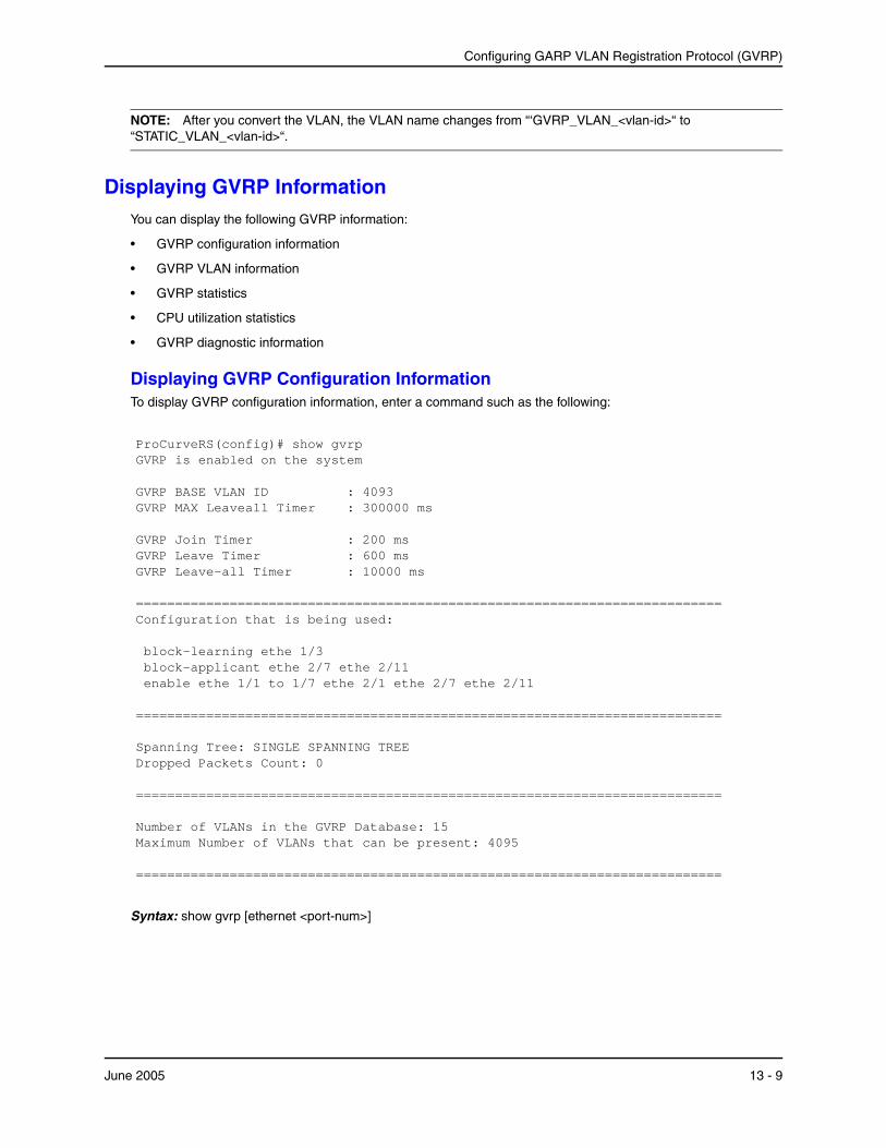
Configuring GARP VLAN Registration Protocol (GVRP)
NOTE: After you convert the VLAN, the VLAN name changes from “‘GVRP_VLAN_<vlan-id>“ to “STATIC_VLAN_<vlan-id>“.
Displaying GVRP InformationYou can display the following GVRP information:
• GVRP configuration information
• GVRP VLAN information
• GVRP statistics
• CPU utilization statistics
• GVRP diagnostic information
Displaying GVRP Configuration InformationTo display GVRP configuration information, enter a command such as the following:
ProCurveRS(config)# show gvrp GVRP is enabled on the system GVRP BASE VLAN ID : 4093 GVRP MAX Leaveall Timer : 300000 ms GVRP Join Timer : 200 ms GVRP Leave Timer : 600 ms GVRP Leave-all Timer : 10000 ms =========================================================================== Configuration that is being used: block-learning ethe 1/3 block-applicant ethe 2/7 ethe 2/11 enable ethe 1/1 to 1/7 ethe 2/1 ethe 2/7 ethe 2/11 =========================================================================== Spanning Tree: SINGLE SPANNING TREE Dropped Packets Count: 0 =========================================================================== Number of VLANs in the GVRP Database: 15 Maximum Number of VLANs that can be present: 4095 ===========================================================================
Syntax: show gvrp [ethernet <port-num>]
June 2005 13 - 9
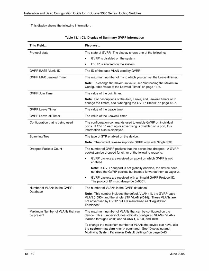
Installation and Basic Configuration Guide for ProCurve 9300 Series Routing Switches
This display shows the following information.
Table 13.1: CLI Display of Summary GVRP Information
This Field... Displays...
Protocol state The state of GVRP. The display shows one of the following:
• GVRP is disabled on the system
• GVRP is enabled on the system
GVRP BASE VLAN ID The ID of the base VLAN used by GVRP.
GVRP MAX Leaveall Timer The maximum number of ms to which you can set the Leaveall timer.
Note: To change the maximum value, see “Increasing the Maximum Configurable Value of the Leaveall Timer” on page 13-6.
GVRP Join Timer The value of the Join timer.
Note: For descriptions of the Join, Leave, and Leaveall timers or to change the timers, see “Changing the GVRP Timers” on page 13-7.
GVRP Leave Timer The value of the Leave timer.
GVRP Leave-all Timer The value of the Leaveall timer.
Configuration that is being used The configuration commands used to enable GVRP on individual ports. If GVRP learning or advertising is disabled on a port, this information also is displayed.
Spanning Tree The type of STP enabled on the device.
Note: The current release supports GVRP only with Single STP.
Dropped Packets Count The number of GVRP packets that the device has dropped. A GVRP packet can be dropped for either of the following reasons:
• GVRP packets are received on a port on which GVRP is not enabled.
Note: If GVRP support is not globally enabled, the device does not drop the GVRP packets but instead forwards them at Layer 2.
• GVRP packets are received with an invalid GARP Protocol ID. The protocol ID must always be 0x0001.
Number of VLANs in the GVRP Database
The number of VLANs in the GVRP database.
Note: This number includes the default VLAN (1), the GVRP base VLAN (4093), and the single STP VLAN (4094). These VLANs are not advertised by GVRP but are maintained as “Registration Forbidden”.
Maximum Number of VLANs that can be present
The maximum number of VLANs that can be configured on the device. This number includes statically configured VLANs, VLANs learned through GVRP, and VLANs 1, 4093, and 4094.
To change the maximum number of VLANs the device can have, use the system-max vlan <num> command. See “Displaying and Modifying System Parameter Default Settings” on page 6-43.
13 - 10 June 2005
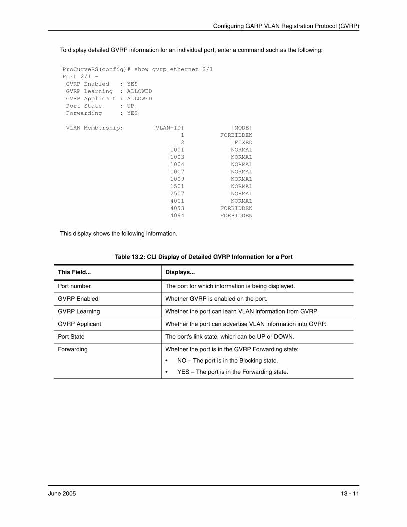
Configuring GARP VLAN Registration Protocol (GVRP)
To display detailed GVRP information for an individual port, enter a command such as the following:
ProCurveRS(config)# show gvrp ethernet 2/1 Port 2/1 - GVRP Enabled : YES GVRP Learning : ALLOWED GVRP Applicant : ALLOWED Port State : UP Forwarding : YES VLAN Membership: [VLAN-ID] [MODE] 1 FORBIDDEN 2 FIXED 1001 NORMAL 1003 NORMAL 1004 NORMAL 1007 NORMAL 1009 NORMAL 1501 NORMAL 2507 NORMAL 4001 NORMAL 4093 FORBIDDEN 4094 FORBIDDEN
This display shows the following information.
Table 13.2: CLI Display of Detailed GVRP Information for a Port
This Field... Displays...
Port number The port for which information is being displayed.
GVRP Enabled Whether GVRP is enabled on the port.
GVRP Learning Whether the port can learn VLAN information from GVRP.
GVRP Applicant Whether the port can advertise VLAN information into GVRP.
Port State The port’s link state, which can be UP or DOWN.
Forwarding Whether the port is in the GVRP Forwarding state:
• NO – The port is in the Blocking state.
• YES – The port is in the Forwarding state.
June 2005 13 - 11

Installation and Basic Configuration Guide for ProCurve 9300 Series Routing Switches
Displaying GVRP VLAN InformationTo display information about all the VLANs on the device, enter the following command:
ProCurveRS(config)# show gvrp vlan brief Number of VLANs in the GVRP Database: 7 Maximum Number of VLANs that can be present: 4095 [VLAN-ID] [MODE] [VLAN-INDEX] 1 STATIC-DEFAULT 0 7 STATIC 2 11 STATIC 4 1001 DYNAMIC 7 1003 DYNAMIC 8 4093 STATIC-GVRP-BASE-VLAN 6 4094 STATIC-SINGLE-SPAN-VLAN 5 ===========================================================================
Syntax: show gvrp vlan all | brief | <vlan-id>
VLAN Membership The VLANs of which the port is a member. For each VLAN, the following information is shown:
• VLAN ID – The VLAN’s ID.
• Mode – The type of VLAN, which can be one of the following:
• FIXED – The port will always be a member of this VLAN and the VLAN will always be advertised on this port by GVRP. A port becomes FIXED when you configure the port as a tagged member of a statically configured VLAN.
• FORBIDDEN – The VLAN is one of the special VLANs that is not advertised or learned by GVRP. In the current release, the following VLANs are forbidden: the default VLAN (1), the GVRP base VLAN (4093), or the Single STP VLAN (4094).
• NORMAL – The port became a member of this VLAN after learning about the VLAN through GVRP. The port’s membership in the VLAN depends on GVRP. If the VLAN is removed from the ports that send GVRP advertisements to this device, then the port will stop being a member of the VLAN.
Table 13.2: CLI Display of Detailed GVRP Information for a Port (Continued)
This Field... Displays...
13 - 12 June 2005

Configuring GARP VLAN Registration Protocol (GVRP)
This display shows the following information.
Table 13.3: CLI Display of Summary VLAN Information for GVRP
This Field... Displays...
Number of VLANs in the GVRP Database
The number of VLANs in the GVRP database.
Note: This number includes the default VLAN (1), the GVRP base VLAN (4093), and the single STP VLAN (4094). These VLANs are not advertised by GVRP but are included in the total count.
Maximum Number of VLANs that can be present
The maximum number of VLANs that can be configured on the device. This number includes statically configured VLANs, VLANs learned through GVRP, and VLANs 1, 4093, and 4094.
To change the maximum number of VLANs the device can have, use the system-max vlan <num> command. See “Displaying and Modifying System Parameter Default Settings” on page 6-43.
VLAN-ID The VLAN ID.
MODE The type of VLAN, which can be one of the following:
• STATIC – The VLAN is statically configured and cannot be removed by GVRP. This includes VLANs you have configured as well as the default VLAN (1), base GVRP VLAN (4093), and Single STP VLAN (4094).
• DYNAMIC – The VLAN was learned through GVRP.
VLAN-INDEX A number used as an index into the internal database.
To display detailed information for a specific VLAN, enter a command such as the following:
ProCurveRS(config)# show gvrp vlan 1001 VLAN-ID: 1001, VLAN-INDEX: 7, STATIC: NO, DEFAULT: NO, BASE-VLAN: NO Timer to Delete Entry Running: NO Legend: [S=Slot] Forbidden Members: None Fixed Members: None Normal(Dynamic) Members: (S2) 1
This display shows the following information.
Table 13.4: CLI Display of Summary VLAN Information for GVRP
This Field... Displays...
VLAN-ID The VLAN ID.
VLAN-INDEX A number used as an index into the internal database.
STATIC Whether the VLAN is a statically configured VLAN.
June 2005 13 - 13
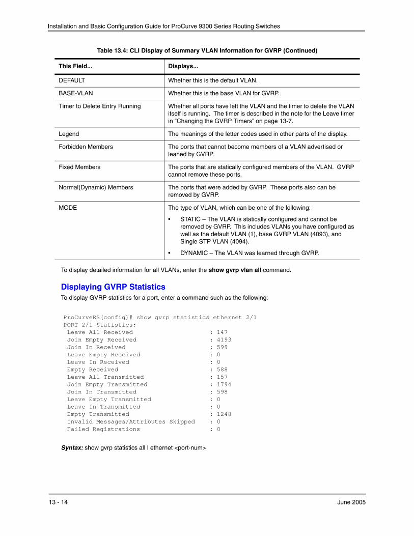
Installation and Basic Configuration Guide for ProCurve 9300 Series Routing Switches
To display detailed information for all VLANs, enter the show gvrp vlan all command.
Displaying GVRP StatisticsTo display GVRP statistics for a port, enter a command such as the following:
ProCurveRS(config)# show gvrp statistics ethernet 2/1 PORT 2/1 Statistics: Leave All Received : 147 Join Empty Received : 4193 Join In Received : 599 Leave Empty Received : 0 Leave In Received : 0 Empty Received : 588 Leave All Transmitted : 157 Join Empty Transmitted : 1794 Join In Transmitted : 598 Leave Empty Transmitted : 0 Leave In Transmitted : 0 Empty Transmitted : 1248 Invalid Messages/Attributes Skipped : 0 Failed Registrations : 0
Syntax: show gvrp statistics all | ethernet <port-num>
DEFAULT Whether this is the default VLAN.
BASE-VLAN Whether this is the base VLAN for GVRP.
Timer to Delete Entry Running Whether all ports have left the VLAN and the timer to delete the VLAN itself is running. The timer is described in the note for the Leave timer in “Changing the GVRP Timers” on page 13-7.
Legend The meanings of the letter codes used in other parts of the display.
Forbidden Members The ports that cannot become members of a VLAN advertised or leaned by GVRP.
Fixed Members The ports that are statically configured members of the VLAN. GVRP cannot remove these ports.
Normal(Dynamic) Members The ports that were added by GVRP. These ports also can be removed by GVRP.
MODE The type of VLAN, which can be one of the following:
• STATIC – The VLAN is statically configured and cannot be removed by GVRP. This includes VLANs you have configured as well as the default VLAN (1), base GVRP VLAN (4093), and Single STP VLAN (4094).
• DYNAMIC – The VLAN was learned through GVRP.
Table 13.4: CLI Display of Summary VLAN Information for GVRP (Continued)
This Field... Displays...
13 - 14 June 2005

Configuring GARP VLAN Registration Protocol (GVRP)
This display shows the following information for the port.
Table 13.5: CLI Display of GVRP Statistics
This Field... Displays...
Leave All Received The number of Leaveall messages received.
Join Empty Received The number of Join Empty messages received.
Join In Received The number of Join In messages received.
Leave Empty Received The number of Leave Empty messages received.
Leave In Received The number of Leave In messages received.
Empty Received The number of Empty messages received.
Leave All Transmitted The number of Leaveall messages sent.
Join Empty Transmitted The number of Join Empty messages sent.
Join In Transmitted The number of Join In messages sent.
Leave Empty Transmitted The number of Leave Empty messages sent.
Leave In Transmitted The number of Leave In messages sent.
Empty Transmitted The number of Empty messages sent.
Invalid Messages/Attributes Skipped The number of invalid messages or attributes received or skipped. This can occur in the following cases:
• The incoming GVRP PDU has an incorrect length.
• "End of PDU" was reached before the complete attribute could be parsed.
• The Attribute Type of the attribute that was being parsed was not the GVRP VID Attribute Type (0x01).
• The attribute that was being parsed had an invalid attribute length.
• The attribute that was being parsed had an invalid GARP event.
• The attribute that was being parsed had an invalid VLAN ID. The valid range is 1 – 4095.
Failed Registrations The number of failed registrations that have occurred. A failed registration can occur for the following reasons:
• Join requests were received on a port that was blocked from learning dynamic VLANs (GVRP Blocking state).
• An entry for a new GVRP VLAN could not be created in the GVRP database.
To display GVRP statistics for all ports, enter the show gvrp statistics all command.
Displaying CPU Utilization StatisticsYou can display CPU utilization statistics for GVRP.
June 2005 13 - 15
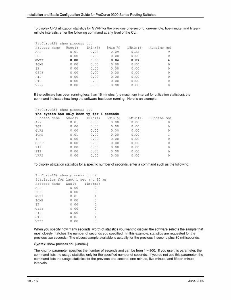
Installation and Basic Configuration Guide for ProCurve 9300 Series Routing Switches
To display CPU utilization statistics for GVRP for the previous one-second, one-minute, five-minute, and fifteen-minute intervals, enter the following command at any level of the CLI:
ProCurveRS# show process cpu Process Name 5Sec(%) 1Min(%) 5Min(%) 15Min(%) Runtime(ms) ARP 0.01 0.03 0.09 0.22 9 BGP 0.00 0.00 0.00 0.00 0 GVRP 0.00 0.03 0.04 0.07 4 ICMP 0.00 0.00 0.00 0.00 0 IP 0.00 0.00 0.00 0.00 0 OSPF 0.00 0.00 0.00 0.00 0 RIP 0.00 0.00 0.00 0.00 0 STP 0.00 0.00 0.00 0.00 0 VRRP 0.00 0.00 0.00 0.00 0
If the software has been running less than 15 minutes (the maximum interval for utilization statistics), the command indicates how long the software has been running. Here is an example:
ProCurveRS# show process cpu The system has only been up for 6 seconds. Process Name 5Sec(%) 1Min(%) 5Min(%) 15Min(%) Runtime(ms) ARP 0.01 0.00 0.00 0.00 0 BGP 0.00 0.00 0.00 0.00 0 GVRP 0.00 0.00 0.00 0.00 0 ICMP 0.01 0.00 0.00 0.00 1 IP 0.00 0.00 0.00 0.00 0 OSPF 0.00 0.00 0.00 0.00 0 RIP 0.00 0.00 0.00 0.00 0 STP 0.00 0.00 0.00 0.00 0 VRRP 0.00 0.00 0.00 0.00 0
To display utilization statistics for a specific number of seconds, enter a command such as the following:
ProCurveRS# show process cpu 2 Statistics for last 1 sec and 80 ms Process Name Sec(%) Time(ms) ARP 0.00 0 BGP 0.00 0 GVRP 0.01 1 ICMP 0.00 0 IP 0.00 0 OSPF 0.00 0 RIP 0.00 0 STP 0.01 1 VRRP 0.00 0
When you specify how many seconds’ worth of statistics you want to display, the software selects the sample that most closely matches the number of seconds you specified. In this example, statistics are requested for the previous two seconds. The closest sample available is actually for the previous 1 second plus 80 milliseconds.
Syntax: show process cpu [<num>]
The <num> parameter specifies the number of seconds and can be from 1 – 900. If you use this parameter, the command lists the usage statistics only for the specified number of seconds. If you do not use this parameter, the command lists the usage statistics for the previous one-second, one-minute, five-minute, and fifteen-minute intervals.
13 - 16 June 2005

Configuring GARP VLAN Registration Protocol (GVRP)
Displaying GVRP Diagnostic InformationTo display diagnostic information, enter the following command:
ProCurveRS# debug gvrp packets GVRP: Packets debugging is on GVRP: 0x2095ced4: 01 80 c2 00 00 21 00 e0 52 ab 87 40 00 3a 42 42 GVRP: 0x2095cee4: 03 00 01 01 02 00 04 05 00 02 04 05 00 07 04 05 GVRP: 0x2095cef4: 00 09 04 05 00 0b 04 02 03 e9 04 01 03 eb 04 01 GVRP: 0x2095cf04: 03 ec 04 01 03 ef 04 01 03 f1 04 01 05 dd 04 01 GVRP: 0x2095cf14: 09 cb 04 01 0f a1 00 00 GVRP: Port 2/1 RCV GVRP: 0x2095ced4: 01 80 c2 00 00 21 00 e0 52 ab 87 40 00 28 42 42 GVRP: 0x2095cee4: 03 00 01 01 04 02 03 e9 04 01 03 eb 04 01 03 ec GVRP: 0x2095cef4: 04 01 03 ef 04 01 03 f1 04 01 05 dd 04 01 09 cb GVRP: 0x2095cf04: 04 01 0f a1 00 00 GVRP: Port 2/1 TX GVRP: 0x207651b8: 01 80 c2 00 00 21 00 04 80 2c 0e 20 00 3a 42 42 GVRP: 0x207651c8: 03 00 01 01 02 00 04 05 03 e9 04 05 03 eb 04 05 GVRP: 0x207651d8: 03 ec 04 05 03 ef 04 05 03 f1 04 05 05 dd 04 05 GVRP: 0x207651e8: 09 cb 04 05 0f a1 04 02 00 02 04 01 00 07 04 01 GVRP: 0x207651f8: 00 09 04 01 00 0b 00 00 GVRP: Port 2/1 TX GVRP: 0x207651b8: 01 80 c2 00 00 21 00 04 80 2c 0e 20 00 18 42 42 GVRP: 0x207651c8: 03 00 01 01 04 02 00 02 04 01 00 07 04 01 00 09 GVRP: 0x207651d8: 04 01 00 0b 00 00
Syntax: debug gvrp packets
Clearing GVRP StatisticsTo clear the GVRP statistics counters, enter a command such as the following:
ProCurveRS# clear gvrp statistics all
This command clears the counters for all ports. To clear the counters for a specific port only, enter a command such as the following:
ProCurveRS# clear gvrp statistics ethernet 2/1
Syntax: clear gvrp statistics all | ethernet <portnum>
CLI ExamplesThe following sections show the CLI commands for implementing the applications of GVRP described in “Application Examples” on page 13-1.
NOTE: Although some of the devices in these configuration examples do not have statically configured VLANs, this is not a requirement. You always can have statically configured VLANs on a device that is running GVRP.
Dynamic Core and Fixed EdgeIn this configuration, the edge devices advertise their statically configured VLANs to the core device. The core device does not have any statically configured VLANs but learns the VLANs from the edge devices.
Enter the following commands on the core device:
ProCurveRS> enable ProCurveRS# configure terminal
June 2005 13 - 17
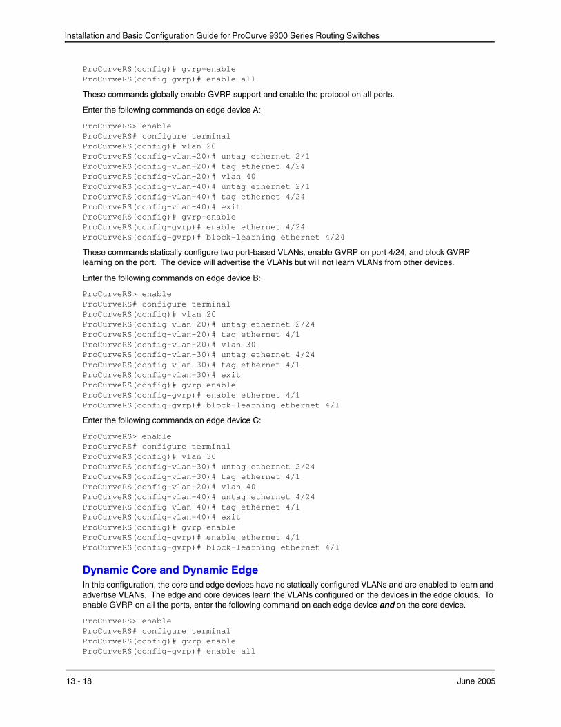
Installation and Basic Configuration Guide for ProCurve 9300 Series Routing Switches
ProCurveRS(config)# gvrp-enable ProCurveRS(config-gvrp)# enable all
These commands globally enable GVRP support and enable the protocol on all ports.
Enter the following commands on edge device A:
ProCurveRS> enable ProCurveRS# configure terminal ProCurveRS(config)# vlan 20 ProCurveRS(config-vlan-20)# untag ethernet 2/1 ProCurveRS(config-vlan-20)# tag ethernet 4/24 ProCurveRS(config-vlan-20)# vlan 40 ProCurveRS(config-vlan-40)# untag ethernet 2/1 ProCurveRS(config-vlan-40)# tag ethernet 4/24 ProCurveRS(config-vlan-40)# exit ProCurveRS(config)# gvrp-enable ProCurveRS(config-gvrp)# enable ethernet 4/24 ProCurveRS(config-gvrp)# block-learning ethernet 4/24
These commands statically configure two port-based VLANs, enable GVRP on port 4/24, and block GVRP learning on the port. The device will advertise the VLANs but will not learn VLANs from other devices.
Enter the following commands on edge device B:
ProCurveRS> enable ProCurveRS# configure terminal ProCurveRS(config)# vlan 20 ProCurveRS(config-vlan-20)# untag ethernet 2/24 ProCurveRS(config-vlan-20)# tag ethernet 4/1 ProCurveRS(config-vlan-20)# vlan 30 ProCurveRS(config-vlan-30)# untag ethernet 4/24 ProCurveRS(config-vlan-30)# tag ethernet 4/1 ProCurveRS(config-vlan-30)# exit ProCurveRS(config)# gvrp-enable ProCurveRS(config-gvrp)# enable ethernet 4/1 ProCurveRS(config-gvrp)# block-learning ethernet 4/1
Enter the following commands on edge device C:
ProCurveRS> enable ProCurveRS# configure terminal ProCurveRS(config)# vlan 30 ProCurveRS(config-vlan-30)# untag ethernet 2/24 ProCurveRS(config-vlan-30)# tag ethernet 4/1 ProCurveRS(config-vlan-20)# vlan 40 ProCurveRS(config-vlan-40)# untag ethernet 4/24 ProCurveRS(config-vlan-40)# tag ethernet 4/1 ProCurveRS(config-vlan-40)# exit ProCurveRS(config)# gvrp-enable ProCurveRS(config-gvrp)# enable ethernet 4/1 ProCurveRS(config-gvrp)# block-learning ethernet 4/1
Dynamic Core and Dynamic EdgeIn this configuration, the core and edge devices have no statically configured VLANs and are enabled to learn and advertise VLANs. The edge and core devices learn the VLANs configured on the devices in the edge clouds. To enable GVRP on all the ports, enter the following command on each edge device and on the core device.
ProCurveRS> enable ProCurveRS# configure terminal ProCurveRS(config)# gvrp-enable ProCurveRS(config-gvrp)# enable all
13 - 18 June 2005

Configuring GARP VLAN Registration Protocol (GVRP)
Fixed Core and Dynamic EdgeIn this configuration, GVRP learning is enabled on the edge devices. The VLANs on the core device are statically configured, and the core device is enabled to advertise its VLANs but not to learn VLANs. The edge devices learn the VLANs from the core.
Enter the following commands on the core device:
ProCurveRS> enable ProCurveRS# configure terminal ProCurveRS(config)# vlan 20 ProCurveRS(config-vlan-20)# tag ethernet 1/24 ProCurveRS(config-vlan-20)# tag ethernet 6/24 ProCurveRS(config-vlan-20)# vlan 30 ProCurveRS(config-vlan-30)# tag ethernet 6/24 ProCurveRS(config-vlan-30)# tag ethernet 8/17 ProCurveRS(config-vlan-30)# vlan 40 ProCurveRS(config-vlan-40)# tag ethernet 1/5 ProCurveRS(config-vlan-40)# tag ethernet 8/17 ProCurveRS(config-vlan-40)# vlan 50 ProCurveRS(config-vlan-50)# untag ethernet 6/1 ProCurveRS(config-vlan-50)# tag ethernet 1/11 ProCurveRS(config-vlan-50)# exit ProCurveRS(config)# gvrp-enable ProCurveRS(config-gvrp)# enable ethernet 1/24 ethernet 6/24 ethernet 8/17 ProCurveRS(config-gvrp)# block-learning ethernet 1/24 ethernet 6/24 ethernet 8/17
These VLAN commands configure VLANs 20, 30, 40, and 50. The GVRP commands enable the protocol on the ports that are connected to the edge devices, and disable VLAN learning on those ports. All the VLANs are advertised by GVRP.
Enter the following commands on edge devices A, B, and C:
ProCurveRS> enable ProCurveRS# configure terminal ProCurveRS(config)# gvrp-enable ProCurveRS(config-gvrp)# enable all ProCurveRS(config-gvrp)# block-applicant all
Fixed Core and Fixed EdgeThe VLANs are statically configured on the core and edge devices. On each edge device, VLAN advertising is enabled but learning is disabled. GVRP is not configured on the core device. This configuration enables the devices in the edge clouds to learn the VLANs configured on the edge devices.
This configuration does not use any GVRP configuration on the core device.
The configuration on the edge device is the same as in “Dynamic Core and Fixed Edge” on page 13-17.
June 2005 13 - 19

Installation and Basic Configuration Guide for ProCurve 9300 Series Routing Switches
13 - 20 June 2005
Chapter 14Enabling the FDP and Reading
Cisco Discovery Protocol (CDP) Packets
Using FDPFDP enables ProCurve Routing Switches to advertise themselves to other ProCurve Routing Switches on the network. When you enable FDP on an HP device, the device periodically advertises information including the following:
• Hostname (device ID)
• Product platform and capability
• Software version
• VLAN and Layer 3 protocol address information for the port sending the update. IP, IPX, and AppleTalk Layer 3 information is supported.
An HP device running FDP sends FDP updates on Layer 2 to MAC address 01-E0-52-CC-CC-CC. Other HP devices listening on that address receive the updates and can display the information in the updates. HP devices can send and receive FDP updates on Ethernet.
FDP is disabled by default.
NOTE: If FDP is not enabled on an HP device that receives an FDP update or the device is running a software release that does not support FDP, the update passes through the device at Layer 2.
Configuring FDPThe following sections describe how to enable FDP and how to change the FDP update and hold timers.
Enabling FDP Globally
To enable an HP device to globally send FDP packets, enter the following command at the global CONFIG level of the CLI:
ProCurveRS(config)# fdp run
Syntax: [no] fdp run
The feature is disabled by default.
Enabling FDP at the Interface Level
Starting in software release 07.6.04, you can enable FDP at the interface level by entering commands such as the following:
June 2005 14 - 1
Installation and Basic Configuration Guide for ProCurve 9300 Series Routing Switches
ProCurveRS(config)# int e 2/1 ProCurveRS(config-if-2/1)# fdp enable
Syntax: ProCurveRSProCurveRS[no] fdp enable
By default, the feature is enabled on an interface once FDP is enabled on the device.
Changing the FDP Update Timer
By default, an HP device enabled for FDP sends an FDP update every 60 seconds. You can change the update timer to a value from 5 – 900 seconds.
To change the FDP update timer, enter a command such as the following at the global CONFIG level of the CLI:
ProCurveRS(config)# fdp timer 120
Syntax: [no] fdp timer <secs>
The <secs> parameter specifies the number of seconds between updates and can be from 5 – 900 seconds. The default is 60 seconds.
Changing the FDP Hold Time
By default, an HP device that receives an FDP update holds the information until one of the following events occurs:
• The device receives a new update.
• 180 seconds have passed since receipt of the last update. This is the hold time.
Once either of these events occurs, the device discards the update.
To change the FDP hold time, enter a command such as the following at the global CONFIG level of the CLI:
ProCurveRS(config)# fdp holdtime 360
Syntax: [no] fdp holdtime <secs>
The <secs> parameter specifies the number of seconds an HP device that receives an FDP update can hold the update before discarding it. You can specify from 10 – 255 seconds. The default is 180 seconds.
Displaying FDP InformationYou can display the following FDP information:
• FDP entries for HP neighbors
• Individual FDP entries
• FDP information for an interface on the device you are managing
• FDP packet statistics
NOTE: If the HP device has intercepted CDP updates, then the CDP information is also displayed.
14 - 2 June 2005
Enabling the FDP and Reading Cisco Discovery Protocol (CDP) Packets
Displaying Neighbor Information
To display a summary list of all the HP neighbors that have sent FDP updates to this HP device, enter the following command:
ProCurveRSA# show fdp neighbor Capability Codes: R - Router, T - Trans Bridge, B - Source Route Bridge S - Switch, H - Host, I - IGMP, r - Repeater (*) indicates a CDP device Device ID Local Int Holdtm Capability Platform Port ID -------------- ------------ ------ ---------- ----------- ------------- 9300 seriesB Eth 2/9 178 Router 9300 series Rou Eth 2/9
Syntax: show fdp neighbor [ethernet <portnum>] [detail]
The ethernet <portnum> parameter lists the information only for updates received on the specified interface.
The detail parameter lists detailed information for each device.
The show fdp neighbor command, without optional parameters, displays the following information.
Table 14.1: Summary FDP and CDP Neighbor Information
This Line... Displays...
Device ID The hostname of the neighbor.
Local Int The interface on which this HP device received an FDP or CDP update for the neighbor.
Holdtm The maximum number of seconds this device can keep the information received in the update before discarding it.
Capability The role the neighbor is capable of playing in the network.
Platform The product platform of the neighbor.
Port ID The interface through which the neighbor sent the update.
To display detailed information, enter the following command:
ProCurveRSA# show fdp neighbor detail Device ID: 9300 seriesB configured as default VLAN1, tag-type8100 Entry address(es): Platform: 9300 series Router, Capabilities: Router Interface: Eth 2/9 Port ID (outgoing port): Eth 2/9 is TAGGED in following VLAN(s): 9 10 11 Holdtime : 176 seconds Version : HP Version 07.6.01b1T53 Compiled on Aug 29 2002 at 10:35:21 labeled as H2R07601b1
June 2005 14 - 3
Installation and Basic Configuration Guide for ProCurve 9300 Series Routing Switches
The show fdp neighbor detail command displays the following information.
Table 14.2: Detailed FDP and CDP Neighbor Information
This Line... Displays...
Device ID The hostname of the neighbor. In addition, this line lists the VLAN memberships and other VLAN information for the neighbor port that sent the update to this device.
Entry address(es) The Layer 3 protocol addresses configured on the neighbor port that sent the update to this device.
Platform The product platform of the neighbor.
Capabilities The role the neighbor is capable of playing in the network.
Interface The interface on which this HP device received an FDP or CDP update for the neighbor.
Port ID The interface through which the neighbor sent the update.
Holdtime The maximum number of seconds this device can keep the information received in the update before discarding it.
Version The software version running on the neighbor.
Displaying FDP Entries
To display the detailed neighbor information for a specific device, enter a command such as the following:
ProCurveRSA# show fdp entry 9300 seriesB Device ID: 9300 seriesB configured as default VLAN1, tag-type8100 Entry address(es): Platform: 9300 series Router, Capabilities: Router Interface: Eth 2/9 Port ID (outgoing port): Eth 2/9 is TAGGED in following VLAN(s): 9 10 11 Holdtime : 176 seconds Version : HP Version 07.6.01b1T53 Compiled on Aug 29 2002 at 10:35:21 labeled as H2R07601b1
Syntax: show fdp entry * | <device-id>
The * | <device-id> parameter specifies the device ID. If you enter *, the detailed updates for all neighbor devices are displayed. If you enter a specific device ID, the update for that device is displayed. For information about the display, see Table 14.2 on page 14-4.
Displaying FDP Information for an Interface
To display FDP information for an interface, enter a command such as the following:
ProCurveRSA# show fdp interface ethernet 2/3 FastEthernet2/3 is up, line protocol is up Encapsulation ethernet Sending FDP packets every 5 seconds Holdtime is 180 seconds
14 - 4 June 2005
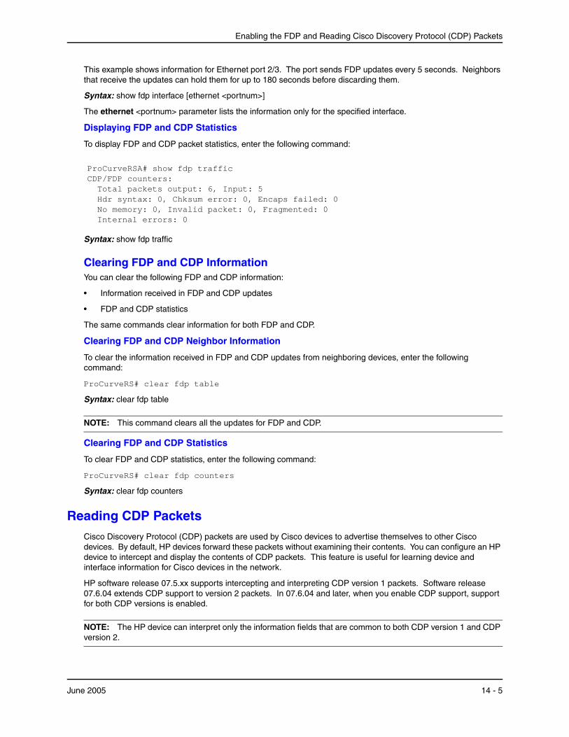
Enabling the FDP and Reading Cisco Discovery Protocol (CDP) Packets
This example shows information for Ethernet port 2/3. The port sends FDP updates every 5 seconds. Neighbors that receive the updates can hold them for up to 180 seconds before discarding them.
Syntax: show fdp interface [ethernet <portnum>]
The ethernet <portnum> parameter lists the information only for the specified interface.
Displaying FDP and CDP Statistics
To display FDP and CDP packet statistics, enter the following command:
ProCurveRSA# show fdp traffic CDP/FDP counters: Total packets output: 6, Input: 5 Hdr syntax: 0, Chksum error: 0, Encaps failed: 0 No memory: 0, Invalid packet: 0, Fragmented: 0 Internal errors: 0
Syntax: show fdp traffic
Clearing FDP and CDP InformationYou can clear the following FDP and CDP information:
• Information received in FDP and CDP updates
• FDP and CDP statistics
The same commands clear information for both FDP and CDP.
Clearing FDP and CDP Neighbor Information
To clear the information received in FDP and CDP updates from neighboring devices, enter the following command:
ProCurveRS# clear fdp table
Syntax: clear fdp table
NOTE: This command clears all the updates for FDP and CDP.
Clearing FDP and CDP Statistics
To clear FDP and CDP statistics, enter the following command:
ProCurveRS# clear fdp counters
Syntax: clear fdp counters
Reading CDP PacketsCisco Discovery Protocol (CDP) packets are used by Cisco devices to advertise themselves to other Cisco devices. By default, HP devices forward these packets without examining their contents. You can configure an HP device to intercept and display the contents of CDP packets. This feature is useful for learning device and interface information for Cisco devices in the network.
HP software release 07.5.xx supports intercepting and interpreting CDP version 1 packets. Software release 07.6.04 extends CDP support to version 2 packets. In 07.6.04 and later, when you enable CDP support, support for both CDP versions is enabled.
NOTE: The HP device can interpret only the information fields that are common to both CDP version 1 and CDP version 2.
June 2005 14 - 5
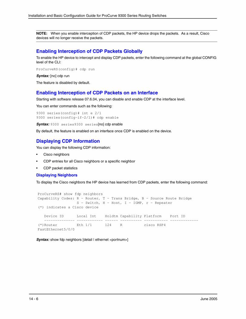
Installation and Basic Configuration Guide for ProCurve 9300 Series Routing Switches
NOTE: When you enable interception of CDP packets, the HP device drops the packets. As a result, Cisco devices will no longer receive the packets.
Enabling Interception of CDP Packets GloballyTo enable the HP device to intercept and display CDP packets, enter the following command at the global CONFIG level of the CLI:
ProCurveRS(config)# cdp run
Syntax: [no] cdp run
The feature is disabled by default.
Enabling Interception of CDP Packets on an InterfaceStarting with software release 07.6.04, you can disable and enable CDP at the interface level.
You can enter commands such as the following:
9300 series(config)# int e 2/1 9300 series(config-if-2/1)# cdp enable
Syntax: 9300 series9300 series[no] cdp enable
By default, the feature is enabled on an interface once CDP is enabled on the device.
Displaying CDP InformationYou can display the following CDP information:
• Cisco neighbors
• CDP entries for all Cisco neighbors or a specific neighbor
• CDP packet statistics
Displaying Neighbors
To display the Cisco neighbors the HP device has learned from CDP packets, enter the following command:
ProCurveRS# show fdp neighbors Capability Codes: R - Router, T - Trans Bridge, B - Source Route Bridge S - Switch, H - Host, I - IGMP, r - Repeater (*) indicates a Cisco device Device ID Local Int Holdtm Capability Platform Port ID -------------- ------------ ------ ---------- ----------- ------------- (*)Router Eth 1/1 124 R cisco RSP4 FastEthernet5/0/0
Syntax: show fdp neighbors [detail | ethernet <portnum>]
14 - 6 June 2005
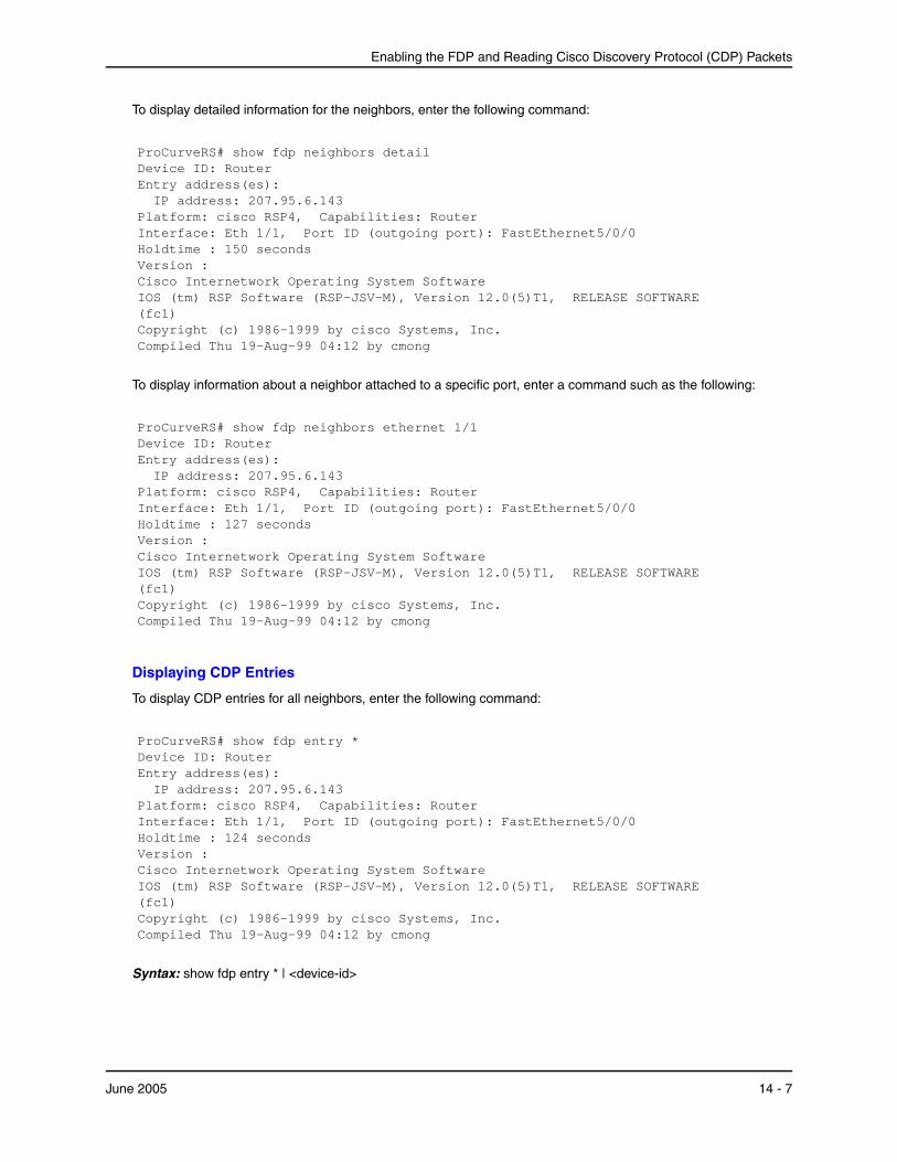
Enabling the FDP and Reading Cisco Discovery Protocol (CDP) Packets
To display detailed information for the neighbors, enter the following command:
ProCurveRS# show fdp neighbors detail Device ID: Router Entry address(es): IP address: 207.95.6.143 Platform: cisco RSP4, Capabilities: Router Interface: Eth 1/1, Port ID (outgoing port): FastEthernet5/0/0 Holdtime : 150 seconds Version : Cisco Internetwork Operating System Software IOS (tm) RSP Software (RSP-JSV-M), Version 12.0(5)T1, RELEASE SOFTWARE (fc1) Copyright (c) 1986-1999 by cisco Systems, Inc. Compiled Thu 19-Aug-99 04:12 by cmong
To display information about a neighbor attached to a specific port, enter a command such as the following:
ProCurveRS# show fdp neighbors ethernet 1/1 Device ID: Router Entry address(es): IP address: 207.95.6.143 Platform: cisco RSP4, Capabilities: Router Interface: Eth 1/1, Port ID (outgoing port): FastEthernet5/0/0 Holdtime : 127 seconds Version : Cisco Internetwork Operating System Software IOS (tm) RSP Software (RSP-JSV-M), Version 12.0(5)T1, RELEASE SOFTWARE (fc1) Copyright (c) 1986-1999 by cisco Systems, Inc. Compiled Thu 19-Aug-99 04:12 by cmong
Displaying CDP Entries
To display CDP entries for all neighbors, enter the following command:
ProCurveRS# show fdp entry * Device ID: Router Entry address(es): IP address: 207.95.6.143 Platform: cisco RSP4, Capabilities: Router Interface: Eth 1/1, Port ID (outgoing port): FastEthernet5/0/0 Holdtime : 124 seconds Version : Cisco Internetwork Operating System Software IOS (tm) RSP Software (RSP-JSV-M), Version 12.0(5)T1, RELEASE SOFTWARE (fc1) Copyright (c) 1986-1999 by cisco Systems, Inc. Compiled Thu 19-Aug-99 04:12 by cmong
Syntax: show fdp entry * | <device-id>
June 2005 14 - 7
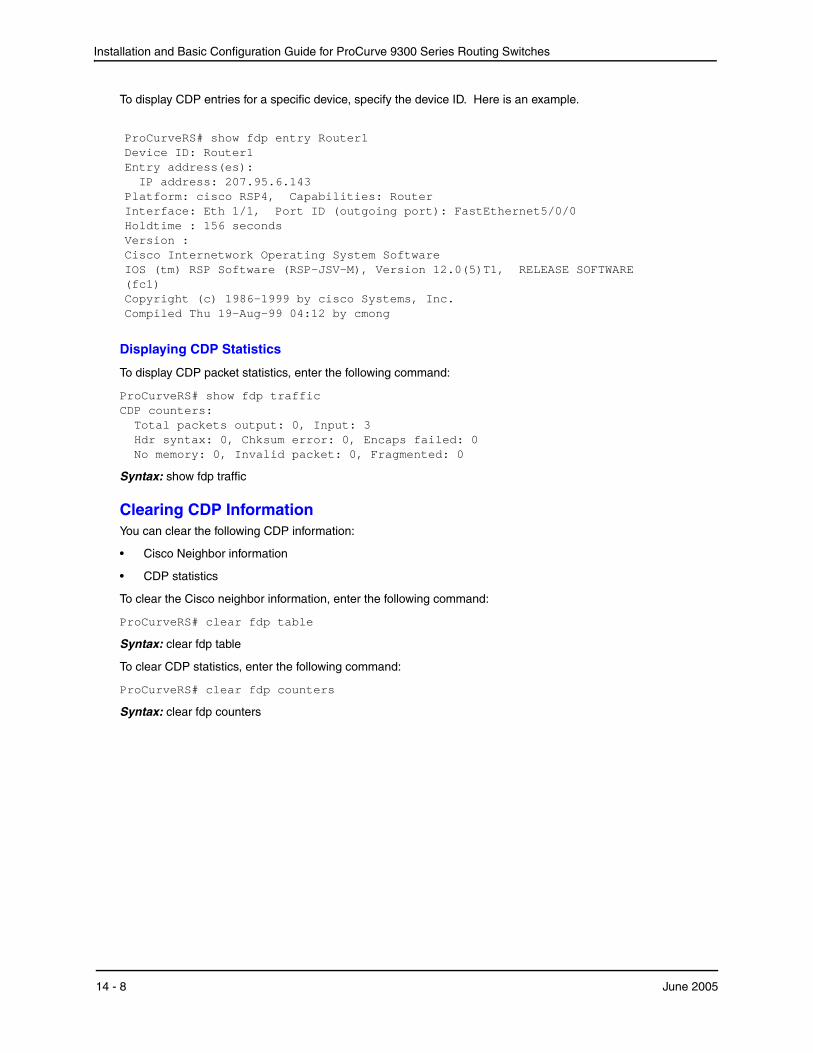
Installation and Basic Configuration Guide for ProCurve 9300 Series Routing Switches
To display CDP entries for a specific device, specify the device ID. Here is an example.
ProCurveRS# show fdp entry Router1 Device ID: Router1 Entry address(es): IP address: 207.95.6.143 Platform: cisco RSP4, Capabilities: Router Interface: Eth 1/1, Port ID (outgoing port): FastEthernet5/0/0 Holdtime : 156 seconds Version : Cisco Internetwork Operating System Software IOS (tm) RSP Software (RSP-JSV-M), Version 12.0(5)T1, RELEASE SOFTWARE (fc1) Copyright (c) 1986-1999 by cisco Systems, Inc. Compiled Thu 19-Aug-99 04:12 by cmong
Displaying CDP Statistics
To display CDP packet statistics, enter the following command:
ProCurveRS# show fdp traffic CDP counters: Total packets output: 0, Input: 3 Hdr syntax: 0, Chksum error: 0, Encaps failed: 0 No memory: 0, Invalid packet: 0, Fragmented: 0
Syntax: show fdp traffic
Clearing CDP InformationYou can clear the following CDP information:
• Cisco Neighbor information
• CDP statistics
To clear the Cisco neighbor information, enter the following command:
ProCurveRS# clear fdp table
Syntax: clear fdp table
To clear CDP statistics, enter the following command:
ProCurveRS# clear fdp counters
Syntax: clear fdp counters
14 - 8 June 2005
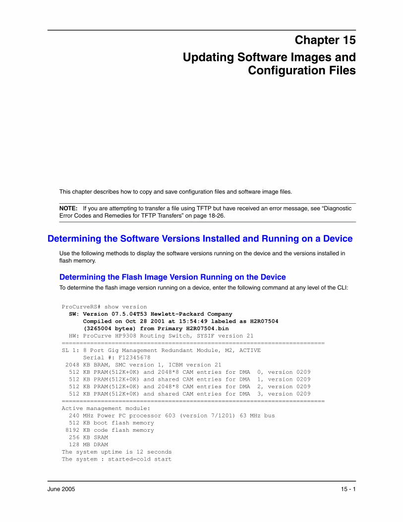
Chapter 15 Updating Software Images and
Configuration Files
This chapter describes how to copy and save configuration files and software image files.
NOTE: If you are attempting to transfer a file using TFTP but have received an error message, see “Diagnostic Error Codes and Remedies for TFTP Transfers” on page 18-26.
Determining the Software Versions Installed and Running on a DeviceUse the following methods to display the software versions running on the device and the versions installed in flash memory.
Determining the Flash Image Version Running on the DeviceTo determine the flash image version running on a device, enter the following command at any level of the CLI:
ProCurveRS# show version SW: Version 07.5.04T53 Hewlett-Packard Company Compiled on Oct 28 2001 at 15:54:49 labeled as H2R07504 (3265004 bytes) from Primary H2R07504.bin HW: ProCurve HP9308 Routing Switch, SYSIF version 21 ========================================================================== SL 1: 8 Port Gig Management Redundant Module, M2, ACTIVE Serial #: F12345678 2048 KB BRAM, SMC version 1, ICBM version 21 512 KB PRAM(512K+0K) and 2048*8 CAM entries for DMA 0, version 0209 512 KB PRAM(512K+0K) and shared CAM entries for DMA 1, version 0209 512 KB PRAM(512K+0K) and 2048*8 CAM entries for DMA 2, version 0209 512 KB PRAM(512K+0K) and shared CAM entries for DMA 3, version 0209 ========================================================================== Active management module: 240 MHz Power PC processor 603 (version 7/1201) 63 MHz bus 512 KB boot flash memory 8192 KB code flash memory 256 KB SRAM 128 MB DRAM The system uptime is 12 seconds The system : started=cold start
June 2005 15 - 1
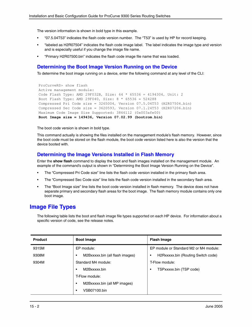
Installation and Basic Configuration Guide for ProCurve 9300 Series Routing Switches
The version information is shown in bold type in this example.
• “07.5.04T53” indicates the flash code version number. The “T53” is used by HP for record keeping.
• “labeled as H2R07504” indicates the flash code image label. The label indicates the image type and version and is especially useful if you change the image file name.
• “Primary H2R07500.bin” indicates the flash code image file name that was loaded.
Determining the Boot Image Version Running on the DeviceTo determine the boot image running on a device, enter the following command at any level of the CLI:
ProCurveRS> show flash Active management module: Code Flash Type: AMD 29F032B, Size: 64 * 65536 = 4194304, Unit: 2 Boot Flash Type: AMD 29F040, Size: 8 * 65536 = 524288 Compressed Pri Code size = 3265004, Version 07.5.04T53 (H2R07504.bin) Compressed Sec Code size = 3620593, Version 07.1.24T53 (H2R07206.bin) Maximum Code Image Size Supported: 3866112 (0x003afe00) Boot Image size = 149436, Version 07.02.99 (bootrom.bin)
The boot code version is shown in bold type.
This command actually is showing the files installed on the management module’s flash memory. However, since the boot code must be stored on the flash module, the boot code version listed here is also the version that the device booted with.
Determining the Image Versions Installed in Flash MemoryEnter the show flash command to display the boot and flash images installed on the management module. An example of the command’s output is shown in “Determining the Boot Image Version Running on the Device”.
• The “Compressed Pri Code size” line lists the flash code version installed in the primary flash area.
• The “Compressed Sec Code size” line lists the flash code version installed in the secondary flash area.
• The “Boot Image size” line lists the boot code version installed in flash memory. The device does not have separate primary and secondary flash areas for the boot image. The flash memory module contains only one boot image.
Image File TypesThe following table lists the boot and flash image file types supported on each HP device. For information about a specific version of code, see the release notes.
Product Boot Image Flash Image
9315M
9308M
9304M
EP module:
• M2Bxxxxx.bin (all flash images)
Standard M4 module:
• M2Bxxxxx.bin
T-Flow module:
• M2Bxxxxx.bin (all MP images)
• VSB07100.bin
EP module or Standard M2 or M4 module:
• H2Rxxxxx.bin (Routing Switch code)
T-Flow module:
• TSPxxxxx.bin (TSP code)
15 - 2 June 2005

Updating Software Images and Configuration Files
Upgrading Software in Release 07.6.04 and Later
NOTE: This section applies to software releases 07.6.04 and later. For upgrade information regarding a specific software release, see the release notes for that release.
Beginning with release 07.6.04, a new and improved compression algorithm is used to generate flash code images. The new compression algorithm allows the software images to contain more features. Boot code version 07.6.04 and later knows how to decompress and load the new images. Boot code versions earlier than 07.6.04 do not know how to decompress and load the new images. In addition, flash code versions 07.6.04 and later know how to copy images that use the new compression method to flash memory. Earlier versions do not.
(To determine which boot code version is running on your device, use the show flash command. The line that begins “Boot Image size” lists the boot code version, at the end of the line.)
If you are upgrading your device from flash code release 07.6.01b or earlier to release 07.6.04, you must first upgrade the management module’s boot code to version 07.6.04 or later. In addition, you must use flash code release 07.6.01b or later to copy the 07.6.04 flash code image file to flash memory.
To summarize, if you are upgrading from a pre-07.6.01b release to release 07.6.04 or later:
1. Upgrade the boot code on the management module to version 07.6.04.
2. Upgrade the flash code on the management module to version 07.6.01b, then reload the software.
3. Upgrade the flash code on the management module to version 07.6.04, then reload the software.
If you are upgrading from release 07.6.01b to release 07.6.04 or higher:
1. Upgrade the boot code on the management module to version 07.6.04.
2. Upgrade the flash code on the management module to version 07.6.04, then reload the software.
Upgrading Software (Non-T-Flow)For easy software image management, all HP devices support the download and upload of software images between the flash modules on the devices and a Trivial File Transfer Protocol (TFTP) server on the network.
The management module contains two flash memory modules:
• Primary flash – The default local storage device for image files and configuration files.
• Secondary flash – A second flash storage device. You can use the secondary flash to store redundant images for additional booting reliability or to preserve one software image while testing another one.
Only one flash device is active at a time. By default, the primary image will become active upon reload.
You can update the software contained on a flash module using TFTP to copy the update image from a TFTP server onto the flash module. In addition, you can copy software images and configuration files from a flash module to a TFTP server.
10 Gigabit Ethernet modules
The Gigabit Ethernet modules do not have boot code separate from the management module. However, they do have Field-Programmable Gate Arrays (FPGAs). See the next column.
The modules do not have flash code separate from the management module. However, they do have Field-Programmable Gate Arrays (FPGAs).
To determine the versions that are running on the modules, enter the show flash command. The version information is listed separately for each 10 Gigabit Ethernet module in the chassis.
Product Boot Image Flash Image
June 2005 15 - 3
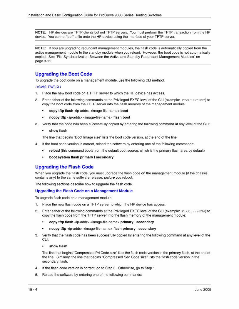
Installation and Basic Configuration Guide for ProCurve 9300 Series Routing Switches
NOTE: HP devices are TFTP clients but not TFTP servers. You must perform the TFTP transaction from the HP device. You cannot “put” a file onto the HP device using the interface of your TFTP server.
NOTE: If you are upgrading redundant management modules, the flash code is automatically copied from the active management module to the standby module when you reload. However, the boot code is not automatically copied. See “File Synchronization Between the Active and Standby Redundant Management Modules” on page 3-11.
Upgrading the Boot CodeTo upgrade the boot code on a management module, use the following CLI method.
USING THE CLI
1. Place the new boot code on a TFTP server to which the HP device has access.
2. Enter either of the following commands at the Privileged EXEC level of the CLI (example: ProCurveRS#) to copy the boot code from the TFTP server into the flash memory of the management module:
• copy tftp flash <ip-addr> <image-file-name> boot
• ncopy tftp <ip-addr> <image-file-name> flash boot
3. Verify that the code has been successfully copied by entering the following command at any level of the CLI:
• show flash
The line that begins “Boot Image size” lists the boot code version, at the end of the line.
4. If the boot code version is correct, reload the software by entering one of the following commands:
• reload (this command boots from the default boot source, which is the primary flash area by default)
• boot system flash primary | secondary
Upgrading the Flash CodeWhen you upgrade the flash code, you must upgrade the flash code on the management module (if the chassis contains any) to the same software release, before you reboot.
The following sections describe how to upgrade the flash code.
Upgrading the Flash Code on a Management Module
To upgrade flash code on a management module:
1. Place the new flash code on a TFTP server to which the HP device has access.
2. Enter either of the following commands at the Privileged EXEC level of the CLI (example: ProCurveRS#) to copy the flash code from the TFTP server into the flash memory of the management module:
• copy tftp flash <ip-addr> <image-file-name> primary | secondary
• ncopy tftp <ip-addr> <image-file-name> flash primary | secondary
3. Verify that the flash code has been successfully copied by entering the following command at any level of the CLI:
• show flash
The line that begins “Compressed Pri Code size” lists the flash code version in the primary flash, at the end of the line. Similarly, the line that begins “Compressed Sec Code size” lists the flash code version in the secondary flash.
4. If the flash code version is correct, go to Step 6. Otherwise, go to Step 1.
5. Reload the software by entering one of the following commands:
15 - 4 June 2005

Updating Software Images and Configuration Files
• reload (this command boots from the default boot source, which is the primary flash area by default)
• boot system flash primary | secondary
NOTE: When you reload the software after upgrading the flash code, the device displays a message stating that the configuration has changed and asking whether you want to save the changes. This occurs even if you do not make any configuration changes. The message occurs because the flash code places its version number in the device's running-config when you load the code onto the device. You can select either to reload without saving the configuration change or save the change and reload. If the only change to the running-config is the flash code version number, then your choice does not affect the operation of the device.
Upgrading Software (T-Flow)If you need to upgrade the boot or flash code on the Management Processor (MP) or a T-Flow Switching Processor (TSP), use the following procedures.
The MP and TSPs run separate software. The MP runs chassis management software. The TSPs run Layer 2 and Layer 3 software. The procedures for upgrading MP and TSPs are different.
NOTE: The MP and TSP flash code must have the same version number. Otherwise, the TSP functions are disabled. You can display the version numbers of the MP and TSPs by entering the show vm-state command. Also, if the version numbers are different, the command output displays a message.
NOTE: If you are upgrading from a TFTP server, make sure the chassis has network (IP) access to the server.
NOTE: If you are upgrading redundant management modules, the flash code is automatically copied from the active management module to the standby module when you reload. However, the boot code is not automatically copied. See “File Synchronization Between the Active and Standby Redundant Management Modules” on page 3-11.
NOTE: When you reload the software after upgrading the flash code, the device displays a message stating that the configuration has changed and asking whether you want to save the changes. This occurs even if you do not make any configuration changes. The message occurs because the flash code places its version number in the device's running-config when you load the code onto the device. You can select either to reload without saving the configuration change or save the change and reload. If the only change to the running-config is the flash code version number, then your choice does not affect the operation of the device.
Upgrading the MP Boot CodeTo upgrade the MP boot code, use the same methods as for any other management module.
USING THE CLI
To upgrade MP boot code from a TFTP server, enter a command such as the following:
ProCurveRS# copy tftp flash 192.168.1.170 M2B07300.bin boot
Syntax: copy tftp flash <ip-addr> <image-file-name> boot
USING THE WEB MANAGEMENT INTERFACE
You cannot perform this procedure using the Web management interface.
Upgrading the TSP Boot CodeTo upgrade the TSP boot code, use the following CLI method.
June 2005 15 - 5
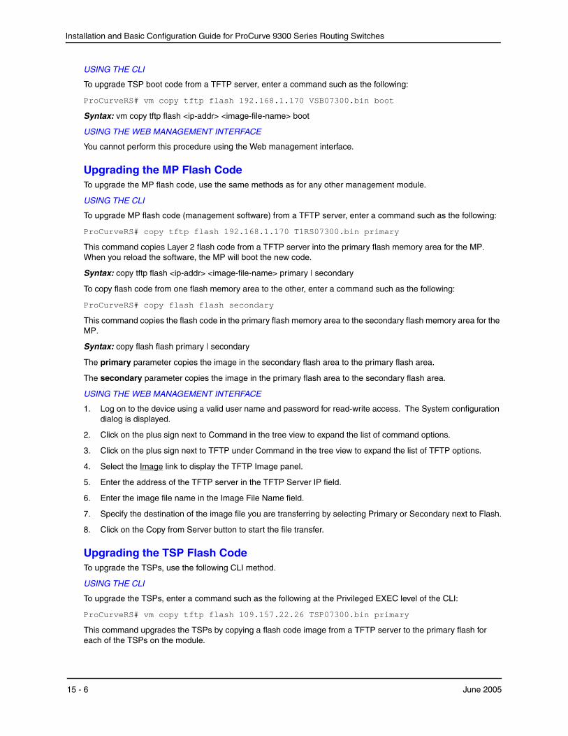
Installation and Basic Configuration Guide for ProCurve 9300 Series Routing Switches
USING THE CLI
To upgrade TSP boot code from a TFTP server, enter a command such as the following:
ProCurveRS# vm copy tftp flash 192.168.1.170 VSB07300.bin boot
Syntax: vm copy tftp flash <ip-addr> <image-file-name> boot
USING THE WEB MANAGEMENT INTERFACE
You cannot perform this procedure using the Web management interface.
Upgrading the MP Flash CodeTo upgrade the MP flash code, use the same methods as for any other management module.
USING THE CLI
To upgrade MP flash code (management software) from a TFTP server, enter a command such as the following:
ProCurveRS# copy tftp flash 192.168.1.170 T1RS07300.bin primary
This command copies Layer 2 flash code from a TFTP server into the primary flash memory area for the MP. When you reload the software, the MP will boot the new code.
Syntax: copy tftp flash <ip-addr> <image-file-name> primary | secondary
To copy flash code from one flash memory area to the other, enter a command such as the following:
ProCurveRS# copy flash flash secondary
This command copies the flash code in the primary flash memory area to the secondary flash memory area for the MP.
Syntax: copy flash flash primary | secondary
The primary parameter copies the image in the secondary flash area to the primary flash area.
The secondary parameter copies the image in the primary flash area to the secondary flash area.
USING THE WEB MANAGEMENT INTERFACE
1. Log on to the device using a valid user name and password for read-write access. The System configuration dialog is displayed.
2. Click on the plus sign next to Command in the tree view to expand the list of command options.
3. Click on the plus sign next to TFTP under Command in the tree view to expand the list of TFTP options.
4. Select the Image link to display the TFTP Image panel.
5. Enter the address of the TFTP server in the TFTP Server IP field.
6. Enter the image file name in the Image File Name field.
7. Specify the destination of the image file you are transferring by selecting Primary or Secondary next to Flash.
8. Click on the Copy from Server button to start the file transfer.
Upgrading the TSP Flash CodeTo upgrade the TSPs, use the following CLI method.
USING THE CLI
To upgrade the TSPs, enter a command such as the following at the Privileged EXEC level of the CLI:
ProCurveRS# vm copy tftp flash 109.157.22.26 TSP07300.bin primary
This command upgrades the TSPs by copying a flash code image from a TFTP server to the primary flash for each of the TSPs on the module.
15 - 6 June 2005

Updating Software Images and Configuration Files
To copy the flash code from the primary flash to the secondary flash for each of the TSPs on the module, enter a command such as the following:
ProCurveRS# vm copy flash flash secondary
Syntax: vm copy tftp flash <tftp-server-ip-addr> <image-file-name> primary | secondary
Syntax: vm copy flash flash primary | secondary
The primary and secondary parameters identify either the primary or secondary flash on the TSPs. For each command, the parameter specifies the destination of the copy operation.
USING THE WEB MANAGEMENT INTERFACE
This procedure is not supported in the Web management interface.
Changing the Default Boot SourceBy default, the T-Flow’s processors boot from the primary flash areas on the module. Each processor boots from its own primary flash. The MP boots first, then the TSPs boot.
You can change the default boot source to one of the following:
• Primary flash (the default)
• Secondary flash
• Interactive
The interactive option pauses during bootup of the TSPs to allow you to select the boot source for the TSPs. You must use this method if you want to boot the TSPs from a TFTP server. Otherwise, this method is used for troubleshooting.
To change the default boot source, use one of the following methods:
USING THE CLI
To change the default boot source, enter commands such as the following at the global CONFIG level of the CLI:
ProCurveRS(config)# vm boot secondary ProCurveRS(config)# write memory
This command configures the module to boot from the secondary flash by default.
NOTE: The write memory command saves the change to the startup-config file. You must save the configuration change for the change to remain in effect after you reboot.
Syntax: vm boot primary | secondary | interactive
The primary and secondary parameters specify a flash memory location. The interactive parameter causes the device to pause during bootup to allow you to specify the boot source for the TSPs. You must use this method if you want to boot the TSPs from a TFTP server. Otherwise, the interactive parameter is used for troubleshooting.
To configure the module to pause during booting to allow you to specify the boot source, enter the following command:
ProCurveRS(config)# vm boot interactive
After you set the boot source to interactive and reboot, enter a command such as the following at the Privileged EXEC level of the CLI to boot the TSPs:
ProCurveRS# vm boot tftp 192.168.1.170 TSP07300.bin
This command copies the TSP flash code image from the specified TFTP server to a TSP address space from which the TSP can boot.
Syntax: vm boot primary | secondary | tftp <ip-addr> <image-file-name>
June 2005 15 - 7
Installation and Basic Configuration Guide for ProCurve 9300 Series Routing Switches
USING THE WEB MANAGEMENT INTERFACE
1. Log on to the device using a valid user name and password for read-write access. The System configuration dialog is displayed.
2. Click on the plus sign next to Configure in the tree view to expand the list of configuration options.
3. Click on the plus sign next to System.
4. Select the Boot Sequence link to display the Boot Sequence List panel.
5. Select the primary boot source by clicking on the radio button next to the name.
NOTE: You cannot select the interactive option using the Web management interface. To select this option, use the CLI.
6. To specify a secondary boot source, go to step 5. The device tries the boot sources in the order you specify them.
7. Select Add to add the change to the device’s running-config.
8. If you want the change to remain in effect following the next system reload, select the Save link to save the configuration change to the startup-config file.
Using SNMP to Upgrade SoftwareYou can use a third-party SNMP management application such as HP OpenView to upgrade software on an HP device.
NOTE: In software releases earlier than 07.5.0.xx, the SNMP agent does not check for type validity with the SNMP version. In software release 07.5.xx and above, the SNMP agent does not send a reply for a varbind, if the type of the varbind is not a known type for that version of SNMP. For example, MIB objects of type Counter64 cannot be retrieved using a v1 packet, as Counter64 is a v2c and v3 type.
NOTE: Make sure you use the correct procedure for your device and processor type. For example, do not use the Management Processor procedure to upgrade the Switching Processors on a module.
NOTE: The syntax shown in this section assumes that you have installed HP OpenView in the “/usr” directory.
NOTE: HP recommends that you make a backup copy of the startup-config file before you upgrade the software. If you need to run an older release, you will need to use the backup copy of the startup-config file.
Management Processorredundant Management ProcessorManagement Processornhphp 22 – Download the flash code into the device’s secondary flash area.
Upgrading Switching Processors on a Routing SwitchUse this procedure to upgrade flash code on the Switching Processors on the T-Flow Redundant Management Module.
1. Configure a read-write community string on the HP device, if one is not already configured. To configure a read-write community string, enter the following command from the global CONFIG level of the CLI: snmp-server community <string> ro | rw where <string> is the community string and can be up to 32 characters long.
2. On the HP device, enter the following command from the global CONFIG level of the CLI: no snmp-server pw-check
15 - 8 June 2005

Updating Software Images and Configuration Files
This command disables password checking for SNMP set requests. If a third-party SNMP management application does not add a password to the password field when it sends SNMP set requests to an HP device, by default the HP device rejects the request.
3. From the command prompt in the UNIX shell, enter the following command: /usr/OV/bin/snmpset -c <rw-community-string> <hp-ip-addr> 1.3.6.1.4.1.1991.1.1.2.1.5.0 ipaddress <tftp-ip-addr> 1.3.6.1.4.1.1991.1.1.2.1.6.0 octetstringascii <file-name> 1.3.6.1.4.1.1991.1.1.2.1.56.0 integer 2 1.3.6.1.4.1.1991.1.1.2.1.57.0 integer <slotnum> 1.3.6.1.4.1.1991.1.1.2.1.7.0 integer <command-integer>
where: <rw-community-string> is a read-write community string configured on the HP device. <hp-ip-addr> is the HP device’s IP address. <tftp-ip-addr> is the TFTP server’s IP address. <file-name> is the image file name. The 2 represents the T-Flow module <slotnum> is the slot that contains the module you are upgrading. To upgrade all modules of the type you specified, enter 0 (zero): <command-integer> is one of the following: 24 – Download the flash code into the device’s primary flash area. 25 – Download the flash code into the device’s secondary flash area.
Changing the Block Size for TFTP File TransfersWhen you use TFTP to copy a file to or from an HP device, the device transfers the data in blocks of 8192 bytes by default. You can change the block size to one of the following if needed:
• 4096
• 2048
• 1024
• 512
• 256
• 128
• 64
• 32
• 16
To change the block size for TFTP file transfers to and from the HP device, use the following CLI method.
USING THE CLI
To change the block size for TFTP file transfers, enter a command such as the following at the global CONFIG level of the CLI:
ProCurveRS(config)# flash 2047
June 2005 15 - 9

Installation and Basic Configuration Guide for ProCurve 9300 Series Routing Switches
set flash copy block size to 2048
Syntax: [no] flash <num>
The software rounds up the <num> value you enter to the next valid power of two, and displays the resulting value. In this example, the software rounds the value up to 2048.
NOTE: If the value you enter is one of the valid powers of two for this parameter, the software still rounds the value up to the next valid power of two. Thus, if you enter 2048, the software rounds the value up to 4096.
USING THE WEB MANAGEMENT INTERFACE
You cannot configure this option using the Web management interface.
Rebooting You can use boot commands to immediately initiate software boots from a software image stored in primary or secondary flash on a ProCurve Routing Switch or from a BootP or TFTP server. You can test new versions of code on a Routing Switch or choose the preferred boot source from the console boot prompt without requiring a system reset.
NOTE: It is very important that you verify a successful TFTP transfer of the boot code before you reset the system. If the boot code is not transferred successfully but you try to reset the system, the system will not have the boot code with which to successfully boot.
By default, the Routing Switch first attempts to boot from the image stored in its primary flash, then its secondary flash, and then from a TFTP server. You can modify this booting sequence at the global CONFIG level of the CLI using the boot system… command.
USING THE CLI
To initiate an immediate boot from the CLI, enter one of the boot system… commands as described in the Command Line Interface Reference for ProCurve 9300/9400 Series Routing Switches.
USING THE WEB MANAGEMENT INTERFACE
To initiate an immediate boot from the primary boot source:
1. Click on the plus sign next to Command in the tree view to expand the list of command options.
2. Select the Reload option.
3. Select Yes when the Web management interface asks you whether you really want to reload.
To initiate an immediate boot from a boot source other than the primary boot source:
1. Click on the plus sign next to Configure in the tree view to expand the list of configuration options.
2. Click on the plus sign next to System in the tree view to expand the list of system configuration options.
15 - 10 June 2005

Updating Software Images and Configuration Files
3. Select the Boot Sequence link to display the following panel.
4. If the boot source with sequence 1 (the primary boot source) listed in the Boot Sequence List is the boot source you want to use for the reload, use the procedure above. The device will use this boot source first. Otherwise, go to the next step.
5. If the boot source with sequence 1 is not the boot source you want to use, select the boot source that is listed as the primary source, then click Delete.
6. Click the boot source you want to use as the primary source. If you select TFTP server, enter the server’s IP address and the image file name you want the device to download from the server.
7. Click the Apply button to save the change to the device’s running-config file.
8. Click the Save link at the bottom of the dialog. Select Yes when prompted to save the configuration change to the startup-config file on the device’s flash memory.
9. Click on the plus sign next to Command in the tree view to expand the list of command options.
10. Select the Reload option.
11. Select Yes when the Web management interface asks you whether you really want to reload.
NOTE: While TFTP transfers are in process, a red bar labeled “processing” is displayed on the screen. When the TFTP transfer is actively transferring image or configuration data, a green bar labeled 'loading' is displayed. When a successful transfer is complete, the message “TFTP transfer complete” is displayed.
If a problem with the transfer occurs, one of the error codes listed in “Diagnostic Error Codes and Remedies for TFTP Transfers” on page 18-26 is displayed.
Loading and Saving Configuration FilesFor easy configuration management, all ProCurve Routing Switches support both the download and upload of configuration files between the Routing Switch and a TFTP server on the network.
You can upload either the startup configuration file or the running configuration file to the TFTP server for backup and use in booting the system.
• Startup configuration file – This file contains the configuration information that is currently saved in flash. To display this file, enter the show configuration command at any CLI prompt.
June 2005 15 - 11
Installation and Basic Configuration Guide for ProCurve 9300 Series Routing Switches
• Running configuration file – This file contains the configuration active in the system RAM but not yet saved to flash. These changes could represent a short-term requirement or general configuration change. To display this file, enter the show running-config or write terminal command at any CLI prompt.
Each device can have one startup configuration file and one running configuration file. The startup configuration file is shared by both flash modules. The running configuration file resides in DRAM.
When you load the startup-config file, the CLI parses the file three times.
1. During the first pass, the parser searches for system-max commands. A system-max command changes the size of statically configured memory.
2. During the second pass, the parser implements the system-max commands if present and also implements trunk configuration commands (trunk command) if present.
3. During the third pass, the parser implements the remaining commands.
Replacing the Startup Configuration with the Running ConfigurationAfter you make configuration changes to the active system, you can save those changes by writing them to flash memory. When you write configuration changes to flash memory, you replace the startup configuration with the running configuration.
USING THE CLI
To replace the startup configuration with the running configuration, enter the following command at any Enable or CONFIG command prompt:
ProCurveRS# write memory
USING THE WEB MANAGEMENT INTERFACE
1. Click on the plus sign next to Command in the tree view to expand the list of command options.
2. Select the Save to Flash option.
3. Select Yes when the Web management interface asks you whether you really want to save the configuration changes to flash.
Replacing the Running Configuration with the Startup ConfigurationIf you want to back out of the changes you have made to the running configuration and return to the startup configuration, use one of the following methods.
USING THE CLI
To replace the startup configuration with the running configuration, enter the following command at the Privileged EXEC level of the CLI:
ProCurveRS# reload
USING THE WEB MANAGEMENT INTERFACE
1. Click on the plus sign next to Command in the tree view to expand the list of command options.
2. Select the Reload option.
3. Select No when the Web management interface asks you whether you really want to save the configuration changes to flash.
Logging Changes to the Startup-Config FileYou can configure an HP device to generate a Syslog message when the startup-config file is changed. The trap is enabled by default.
The following Syslog message is generated when the startup-config file is changed:
startup-config was changed
15 - 12 June 2005
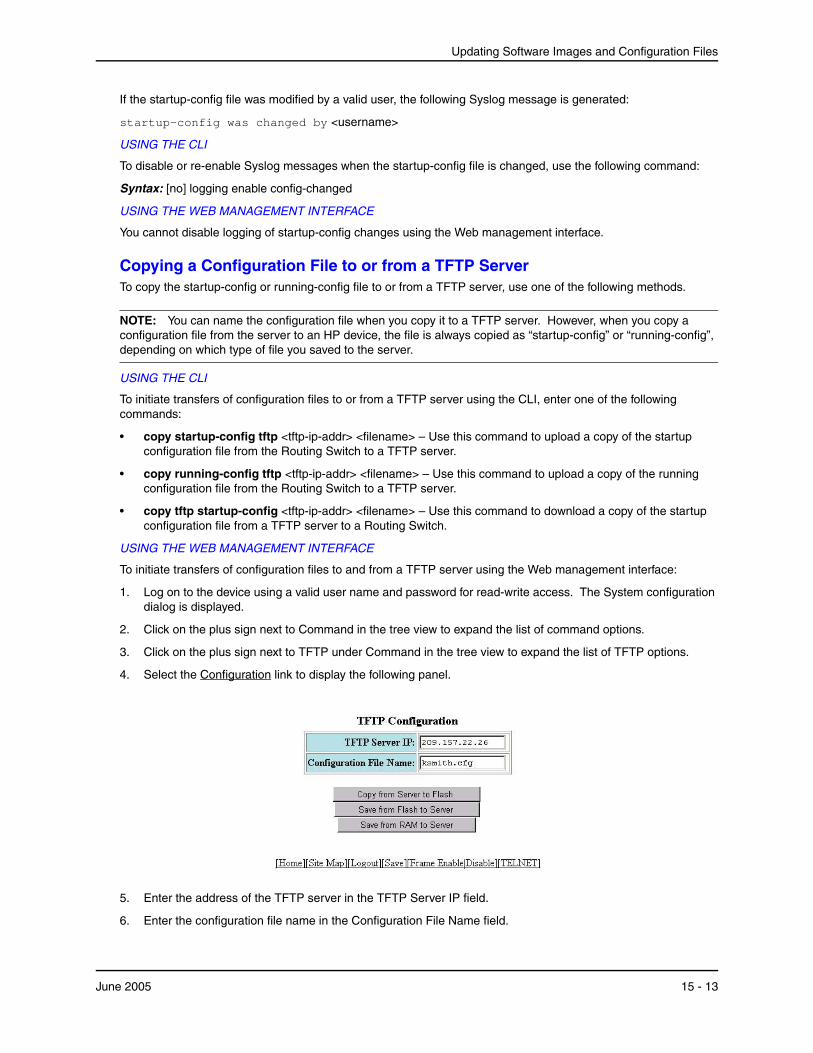
Updating Software Images and Configuration Files
If the startup-config file was modified by a valid user, the following Syslog message is generated:
startup-config was changed by <username>
USING THE CLI
To disable or re-enable Syslog messages when the startup-config file is changed, use the following command:
Syntax: [no] logging enable config-changed
USING THE WEB MANAGEMENT INTERFACE
You cannot disable logging of startup-config changes using the Web management interface.
Copying a Configuration File to or from a TFTP ServerTo copy the startup-config or running-config file to or from a TFTP server, use one of the following methods.
NOTE: You can name the configuration file when you copy it to a TFTP server. However, when you copy a configuration file from the server to an HP device, the file is always copied as “startup-config” or “running-config”, depending on which type of file you saved to the server.
USING THE CLI
To initiate transfers of configuration files to or from a TFTP server using the CLI, enter one of the following commands:
• copy startup-config tftp <tftp-ip-addr> <filename> – Use this command to upload a copy of the startup configuration file from the Routing Switch to a TFTP server.
• copy running-config tftp <tftp-ip-addr> <filename> – Use this command to upload a copy of the running configuration file from the Routing Switch to a TFTP server.
• copy tftp startup-config <tftp-ip-addr> <filename> – Use this command to download a copy of the startup configuration file from a TFTP server to a Routing Switch.
USING THE WEB MANAGEMENT INTERFACE
To initiate transfers of configuration files to and from a TFTP server using the Web management interface:
1. Log on to the device using a valid user name and password for read-write access. The System configuration dialog is displayed.
2. Click on the plus sign next to Command in the tree view to expand the list of command options.
3. Click on the plus sign next to TFTP under Command in the tree view to expand the list of TFTP options.
4. Select the Configuration link to display the following panel.
5. Enter the address of the TFTP server in the TFTP Server IP field.
6. Enter the configuration file name in the Configuration File Name field.
June 2005 15 - 13
Installation and Basic Configuration Guide for ProCurve 9300 Series Routing Switches
7. Click on one of the following buttons to start the file transfer:
• Copy from Server to Flash – downloads the configuration file from the TFTP server into the device’s flash. (The flash area holds only one configuration file, so you cannot specify a primary or secondary save location for the file.)
• Save from Flash to Server – uploads the startup-config file (the configuration file) to the TFTP server using the name you entered in the Configuration File Name field.
• Save from RAM to Server – uploads the running-config file to the TFTP server using the name you entered in the Configuration File Name field. The running-config file contains the active system configuration, which may not match the contents of the startup-config file if you have made configuration changes but not saved them to flash. To synchronize the running-config and startup-config files, use the procedure in “Replacing the Startup Configuration with the Running Configuration” on page 18-18.
NOTE: While TFTP transfers are in process, a red bar labeled “processing” is displayed on the screen. When the TFTP transfer is actively transferring image or configuration data, a green bar labeled “loading” is displayed. When a successful transfer is complete, the message “TFTP transfer complete” is displayed.
If a problem with the transfer occurs, one of the error codes listed in “Diagnostic Error Codes and Remedies for TFTP Transfers” on page 18-26 is displayed.
Dynamic Configuration LoadingYou can load dynamic configuration commands (commands that do not require a reload to take effect) from a file on a TFTP server into an HP device’s running-config. You can make configuration changes off-line, then load the changes directly into the device’s running-config, without reloading the software.
Usage Considerations
• Use this feature only to load configuration information that does not require a software reload to take effect. For example, you cannot use this feature to change statically configured memory (system-max command) or to enter trunk group configuration information into the running-config.
• Do not use this feature if you have deleted a trunk group but have not yet placed the changes into effect by saving the configuration and then reloading. When you delete a trunk group, the command to configure the trunk group is removed from the device’s running-config, but the trunk group remains active. To finish deleting a trunk group, save the configuration (to the startup-config file), then reload the software. After you reload the software, then you can load the configuration from the file.
• Do not load port configuration information for secondary ports in a trunk group. Since all ports in a trunk group use the port configuration settings of the primary port in the group, the software cannot implement the changes to the secondary port.
Preparing the Configuration File
A configuration file that you create must follow the same syntax rules as the startup-config file the device creates.
• The configuration file is a script containing CLI configuration commands. The CLI reacts to each command entered from the file in the same way the CLI reacts to the command if you enter it. For example, if the command results in an error message or a change to the CLI configuration level, the software responds by displaying the message or changing the CLI level.
• The software retains the running-config that is currently on the device, and changes the running-config only by adding new commands from the configuration file. If the running config already contains a command that is also in the configuration file you are loading, the CLI rejects the new command as a duplicate and displays an error message. For example, if the running-config already contains a a command that configures ACL 1, the software rejects ACL 1 in the configuration file, and displays a message that ACL 1 is already configured.
• The file can contain global CONFIG commands or configuration commands for interfaces, routing protocols, and so on. You cannot enter User EXEC or Privileged EXEC commands.
15 - 14 June 2005

Updating Software Images and Configuration Files
• The default CLI configuration level in a configuration file is the global CONFIG level. Thus, the first command in the file must be a global CONFIG command or “ ! ”. The ! (exclamation point) character means “return to the global CONFIG level”.
NOTE: You can enter text following “ ! “ as a comment. However, the “ !” is not a comment marker. It returns the CLI to the global configuration level.
NOTE: In software releases earlier than 07.1.x, the CLI ignores the “ ! “ instead of changing the CLI to the global CONFIG level, when you load the configuration using the copy tftp running-config <ip-addr> <filename> command. In software release 07.1.x and later, the CLI does change the CLI to the global CONFIG level, when you load the configuration using the copy tftp running-config <ip-addr> <filename> command or the ncopy tftp <ip-addr> <filename> running-config command. In all releases, the CLI changes to the global CONFIG level if you load the configuration as a startup-config file instead of the running-config (using the copy tftp startup-config <ip-addr> <filename> command or ncopy tftp <ip-addr> <from-name> startup-config command).
NOTE: If you copy-and-paste a configuration into a management session, the CLI ignores the “ ! “ instead of changing the CLI to the global CONFIG level. As a result, you might get different results if you copy-and-paste a configuration instead of loading the configuration using TFTP.
• Make sure you enter each command at the correct CLI level. Since some commands have identical forms at both the global CONFIG level and individual configuration levels, if the CLI’s response to the configuration file results in the CLI entering a configuration level you did not intend, then you can get unexpected results. For example, if a trunk group is active on the device, and the configuration file contains a command to disable STP on one of the secondary ports in the trunk group, the CLI rejects the commands to enter the interface configuration level for the port and moves on to the next command in the file you are loading. If the next command is a spanning-tree command whose syntax is valid at the global CONFIG level as well as the interface configuration level, then the software applies the command globally. Here is an example: The configuration file contains these commands:
interface ethernet 4/2 no spanning-tree
The CLI responds like this:
ProCurveRS(config)# interface ethernet 4/2 Error - cannot configure secondary ports of a trunk ProCurveRS(config)# no spanning-tree ProCurveRS(config)#
• If the file contains commands that must be entered in a specific order, the commands must appear in the file in the required order. For example, if you want to use the file to replace an IP address on an interface, you must first remove the old address using “no” in front of the ip address command, then add the new address. Otherwise, the CLI displays an error message and does not implement the command. Here is an example:
The configuration file contains these commands:
interface ethernet 3/11 ip address 10.10.10.69/24
The running-config already has a command to add an address to 3/11, so the CLI responds like this:
ProCurveRS(config)# interface ethernet 3/11 ProCurveRS(config-if-e100-3/1)# ip add 10.10.10.69/24 Error: can only assign one primary ip address per subnet ProCurveRS(config-if-e100-3/1)#
June 2005 15 - 15
Installation and Basic Configuration Guide for ProCurve 9300 Series Routing Switches
To successfully replace the address, enter commands into the file as follows:
interface ethernet 3/11 no ip address 20.20.20.69/24 ip address 10.10.10.69/24
This time, the CLI accepts the command, and no error message is displayed:
ProCurveRS(config)# interface ethernet 3/11 ProCurveRS(config-if-e100-3/1)# no ip add 20.20.20.69/24 ProCurveRS(config-if-e100-3/1)# ip add 10.10.10.69/24 ProCurveRS(config-if-e100-3/1)
• Always use the end command at the end of the file. The end command must appear on the last line of the file, by itself.
Loading the Configuration Information into the Running-Config
You can load the configuration information from a TFTP server. To load the file from a TFTP server, use either of the following commands:
• copy tftp running-config <ip-addr> <filename>
• ncopy tftp <ip-addr> <filename> running-config
Maximum File Sizes for Startup-Config File and Running-ConfigEach HP device has a maximum allowable size for the running-config and the startup-config file. If you use TFTP to load additional information into a device’s running-config or startup-config file, it is possible to exceed the maximum allowable size. If this occurs, you will not be able to save the configuration changes.
The following table lists the maximum size for the running-config and the startup-config file on HP devices.
Product type Maximum running-config and startup-config file sizes
a.The running-config and startup-config file can each be the size listed. The maximum size is not the maximum combined size for the running-config and startup-config files.
a
9300 series using Management 2 modules or higher
256K
9304M or 9308M using a Management 1 module
128K
Determining the Size of the Running-Config in Releases 07.6.04 and Later
In software releases 07.6.04 and later, the show running-config, write terminal, and show configuration commands displays the size of the running-config file. In releases prior to 07.6.04, this information was not readily available.
For example:
ProCurveRS# show running-config !Building configuration... !Current configuration : 449 bytes
(remaining lines omitted)
ProCurveRS# show configuration !Using 449 out of 262142 bytes
(remaining lines omitted)
15 - 16 June 2005

Updating Software Images and Configuration Files
NOTE: The lines displaying the size of the running-config are not actually part of the running-config itself.
Determining the Size of the Running-Config in Releases Prior to 07.6.04
To determine the size of an HP device’s running-config or startup-config file, copy it to a TFTP server, then use the directory services on the server to list the size of the copied file. To copy the running-config or startup-config file to a TFTP server, use one of the following commands.
• Commands to copy the running-config to a TFTP server:
• copy running-config tftp <ip-addr> <filename>
• ncopy running-config tftp <ip-addr> <from-name>
• Commands to copy the startup-config file to a TFTP server:
• copy startup-config tftp <ip-addr> <filename>
• ncopy startup-config tftp <ip-addr> <from-name>
Using SNMP to Save and Load Configuration InformationYou can use an third-party SNMP management application such as HP OpenView to save and load an HP device’s configuration. To save and load configuration information using HP OpenView, use the following procedure.
NOTE: The syntax shown in this section assumes that you have installed HP OpenView in the “/usr” directory.
1. Configure a read-write community string on the HP device, if one is not already configured. To configure a read-write community string, enter the following command from the global CONFIG level of the CLI: snmp-server community <string> ro | rw where <string> is the community string and can be up to 32 characters long.
2. On the HP device, enter the following command from the global CONFIG level of the CLI: no snmp-server pw-check This command disables password checking for SNMP set requests. If a third-party SNMP management application does not add a password to the password field when it sends SNMP set requests to an HP device, by default the HP device rejects the request.
3. From the command prompt in the UNIX shell, enter the following command: /usr/OV/bin/snmpset -c <rw-community-string> <hp-ip-addr> 1.3.6.1.4.1.1991.1.1.2.1.5.0 ipaddress <tftp-ip-addr> 1.3.6.1.4.1.1991.1.1.2.1.8.0 octetstringascii <config-file-name> 1.3.6.1.4.1.1991.1.1.2.1.9.0 integer <command-integer>
where: <rw-community-string> is a read-write community string configured on the HP device. <hp-ip-addr> is the HP device’s IP address. <tftp-ip-addr> is the TFTP server’s IP address. <config-file-name> is the configuration file name. <command-integer> is one of the following: 20 – Upload the startup-config file from the HP device’s flash memory to the TFTP server.
June 2005 15 - 17
Installation and Basic Configuration Guide for ProCurve 9300 Series Routing Switches
21 – Download a startup-config file from a TFTP server to the HP device’s flash memory. 22 – Upload the running-config from the HP device’s flash memory to the TFTP server. 23 – Download a configuration file from a TFTP server into the HP device’s running-config.
NOTE: Command option 23 adds configuration information to the running-config on the device, and does not replace commands. If you want to replace configuration information in the device, use “no” forms of the configuration commands to remove the configuration information, then use configuration commands to create the configuration information you want. Follow the guidelines in “Dynamic Configuration Loading” on page 18-20.
Erasing Image and Configuration FilesTo erase software images or configuration files, use the commands described below. These commands are valid at the Privileged EXEC level of the CLI.
USING THE CLI
• erase flash primary erases the image stored in primary flash of the system.
• erase flash secondary erases the image stored in secondary flash of the system.
• erase startup-config erases the configuration stored in the startup configuration file; however, the running configuration remains intact until system reboot.
USING THE WEB MANAGEMENT INTERFACE
You cannot delete image or configuration files using the Web management interface.
Scheduling a System ReloadIn addition to reloading the system manually, you can configure the HP device to reload itself at a specific time or after a specific amount of time has passed.
NOTE: The scheduled reload feature requires the system clock. You can use a Simple Network Time Protocol (SNTP) server to set the clock or you can set the device clock manually. See “Specifying a Simple Network Time Protocol (SNTP) Server” on page 8-12 or “Setting the System Clock” on page 8-14.
Reloading at a Specific TimeTo schedule a system reload for a specific time, use one of the following methods.
USING THE CLI
To schedule a system reload from the primary flash module for 6:00:00 AM, January 19, 2004, enter the following command at the global CONFIG level of the CLI:
ProCurveRS# reload at 06:00:00 01-19-04
Syntax: reload at <hh:mm:ss> <mm-dd-yy> [primary | secondary]
<hh:mm:ss> is the hours, minutes, and seconds.
<mm-dd-yy> is the month, day, and year.
primary | secondary specifies whether the reload is to occur from the primary code flash module or the secondary code flash module. The default is primary.
USING THE WEB MANAGEMENT INTERFACE
You cannot schedule a system reload using the Web management interface.
15 - 18 June 2005

Updating Software Images and Configuration Files
Reloading after a Specific Amount of TimeTo schedule a system reload to occur after a specific amount of time has passed on the system clock, use one of the following methods.
USING THE CLI
To schedule a system reload from the secondary flash one day and 12 hours later, enter the following command at the global CONFIG level of the CLI:
ProCurveRS# reload after 01:12:00 secondary
Syntax: reload after <dd:hh:mm> [primary | secondary]
<dd:hh:mm> is the number of days, hours, and minutes.
primary | secondary specifies whether the reload is to occur from the primary code flash module or the secondary code flash module.
USING THE WEB MANAGEMENT INTERFACE
You cannot schedule a system reload using the Web management interface.
Displaying the Amount of Time Remaining Before a Scheduled ReloadTo display how much time is remaining before a scheduled system reload takes place, use one of the following methods.
USING THE CLI
To display how much time is remaining before a scheduled system reload, enter the following command from any level of the CLI:
ProCurveRS# show reload
USING THE WEB MANAGEMENT INTERFACE
You cannot display information about a scheduled reload using the Web management interface.
Canceling a Scheduled ReloadTo cancel a scheduled reload, use one of the following methods.
USING THE CLI
To cancel a scheduled system reload using the CLI, enter the following command at the global CONFIG level:
ProCurveRS# reload cancel
USING THE WEB MANAGEMENT INTERFACE
You cannot cancel a scheduled reload using the Web management interface.
June 2005 15 - 19
Installation and Basic Configuration Guide for ProCurve 9300 Series Routing Switches
Diagnostic Error Codes and Remedies for TFTP TransfersIf an error occurs with a TFTP transfer to or from a ProCurve Routing Switch, one of the following error codes is displayed.
Error code
Message Explanation and action
1 Flash read preparation failed. A flash error occurred during the download.
Retry the download. If it fails again, contact customer support.
2 Flash read failed.
3 Flash write preparation failed.
4 Flash write failed.
5 TFTP session timeout. TFTP failed because of a time out.
Check IP connectivity and make sure the TFTP server is running.
6 TFTP out of buffer space. The file is larger than the amount of room on the device or TFTP server.
If you are copying an image file to flash, first copy the other image to your TFTP server, then delete it from flash. (Use the erase flash... CLI command at the Privileged EXEC level to erase the image in the flash.)
If you are copying a configuration file to flash, edit the file to remove unneeded information, then try again.
7 TFTP busy, only one TFTP session can be active.
Another TFTP transfer is active on another CLI session or Web management session.
Wait, then retry the transfer.
8 File type check failed. You accidentally attempted to copy the incorrect image code into the system.
Retry the transfer using the correct image.
16 TFTP remote - general error. The TFTP configuration has an error. The specific error message describes the error.
Correct the error, then retry the transfer.
17 TFTP remote - no such file.
18 TFTP remote - access violation.
19 TFTP remote - disk full.
20 TFTP remote - illegal operation.
21 TFTP remote - unknown transfer ID.
22 TFTP remote - file already exists.
23 TFTP remote - no such user.
15 - 20 June 2005
Appendix AUsing Syslog
This appendix describes how to display Syslog messages and how to configure the Syslog facility, and lists the Syslog messages that a ProCurve Routing Switch can display during standard operation.
NOTE: This appendix does not list Syslog messages that can be displayed when a debug option is enabled. For information about Syslog messages that are displayed by a debug option, see the Diagnostic Guide for ProCurve 9300/9400 Series Routing Switches.
OverviewAn HP device’s software can write syslog messages to provide information at the following severity levels:
• Emergencies
• Alerts
• Critical
• Errors
• Warnings
• Notifications
• Informational
• Debugging
The device writes the messages to a local buffer. In software release earlier than 07.6.04, the local buffer can hold up to 100 entries. Beginning with software release 07.6.04, the buffer can hold up to 1000 entries.
You also can specify the IP address or host name of up to six Syslog servers. When you specify a Syslog server, the HP device writes the messages both to the system log and to the Syslog server.
Using a Syslog server ensures that the messages remain available even after a system reload. The HP device’s local Syslog buffer is cleared during a system reload or reboot, but the Syslog messages sent to the Syslog server remain on the server.
The Syslog service on a Syslog server receives logging messages from applications on the local host or from devices such as a Routing Switch. Syslog adds a time stamp to each received message and directs messages to a log file. Most Unix workstations come with Syslog configured. Some third party vendor products also provide Syslog running on NT.
June 2005 A - 1
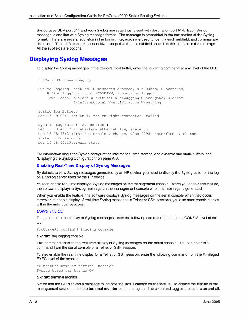
Installation and Basic Configuration Guide for ProCurve 9300 Series Routing Switches
Syslog uses UDP port 514 and each Syslog message thus is sent with destination port 514. Each Syslog message is one line with Syslog message format. The message is embedded in the text portion of the Syslog format. There are several subfields in the format. Keywords are used to identify each subfield, and commas are delimiters. The subfield order is insensitive except that the text subfield should be the last field in the message. All the subfields are optional.
Displaying Syslog MessagesTo display the Syslog messages in the device’s local buffer, enter the following command at any level of the CLI:
ProCurveRS> show logging Syslog logging: enabled (0 messages dropped, 0 flushes, 0 overruns) Buffer logging: level ACDMEINW, 3 messages logged level code: A=alert C=critical D=debugging M=emergency E=error I=informational N=notification W=warning Static Log Buffer: Dec 15 19:04:14:A:Fan 1, fan on right connector, failed Dynamic Log Buffer (50 entries): Dec 15 18:46:17:I:Interface ethernet 1/4, state up Dec 15 18:45:21:I:Bridge topology change, vlan 4095, interface 4, changed state to forwarding Dec 15 18:45:15:I:Warm start
For information about the Syslog configuration information, time stamps, and dynamic and static buffers, see “Displaying the Syslog Configuration” on page A-3.
Enabling Real-Time Display of Syslog Messages
By default, to view Syslog messages generated by an HP device, you need to display the Syslog buffer or the log on a Syslog server used by the HP device.
You can enable real-time display of Syslog messages on the management console. When you enable this feature, the software displays a Syslog message on the management console when the message is generated.
When you enable the feature, the software displays Syslog messages on the serial console when they occur. However, to enable display of real-time Syslog messages in Telnet or SSH sessions, you also must enable display within the individual sessions.
USING THE CLI
To enable real-time display of Syslog messages, enter the following command at the global CONFIG level of the CLI:
ProCurveRS(config)# logging console
Syntax: [no] logging console
This command enables the real-time display of Syslog messages on the serial console. You can enter this command from the serial console or a Telnet or SSH session.
To also enable the real-time display for a Telnet or SSH session, enter the following command from the Privileged EXEC level of the session:
telnet@ProCurveRS# terminal monitor Syslog trace was turned ON
Syntax: terminal monitor
Notice that the CLI displays a message to indicate the status change for the feature. To disable the feature in the management session, enter the terminal monitor command again. The command toggles the feature on and off.
A - 2 June 2005

Using Syslog
telnet@ProCurveRS# terminal monitor Syslog trace was turned OFF
Here is an example of how the Syslog messages are displayed:
telnet@ProCurveRS# terminal monitor Syslog trace was turned ON SYSLOG: <9>ProCurveRS, Power supply 2, power supply on left connector, failed SYSLOG: <14>ProCurveRS, Interface ethernet 1/6, state down SYSLOG: <14>ProCurveRS, Interface ethernet 1/2, state up
Configuring the Syslog ServiceThe procedures in this section describe how to perform the following Syslog configuration tasks:
• Specify a Syslog server. You can configure the HP device to use up to six Syslog servers. (Use of a Syslog server is optional. The system can hold up to 100 Syslog messages in an internal buffer.)
• Change the level of messages the system logs.
• Change the number of messages the local Syslog buffer can hold.
• Display the Syslog configuration.
• Clear the local Syslog buffer.
Logging is enabled by default, with the following settings:
• Messages of all severity levels (Emergencies – Debugging) are logged.
• By default, up to 50 messages are retained in the local Syslog buffer. This can be changed.
• No Syslog server is specified.
Displaying the Syslog ConfigurationTo display the Syslog parameters currently in effect on an HP device, enter the following command from any level of the CLI:
ProCurveRS> show logging Syslog logging: enabled (0 messages dropped, 0 flushes, 0 overruns) Buffer logging: level ACDMEINW, 3 messages logged level code: A=alert C=critical D=debugging M=emergency E=error I=informational N=notification W=warning Static Log Buffer: Dec 15 19:04:14:A:Fan 1, fan on right connector, failed Dynamic Log Buffer (50 entries): Dec 15 18:46:17:I:Interface ethernet 1/4, state up Dec 15 18:45:21:I:Bridge topology change, vlan 4095, interface 4, changed state to forwarding Dec 15 18:45:15:I:Warm start
Syntax: show logging
June 2005 A - 3
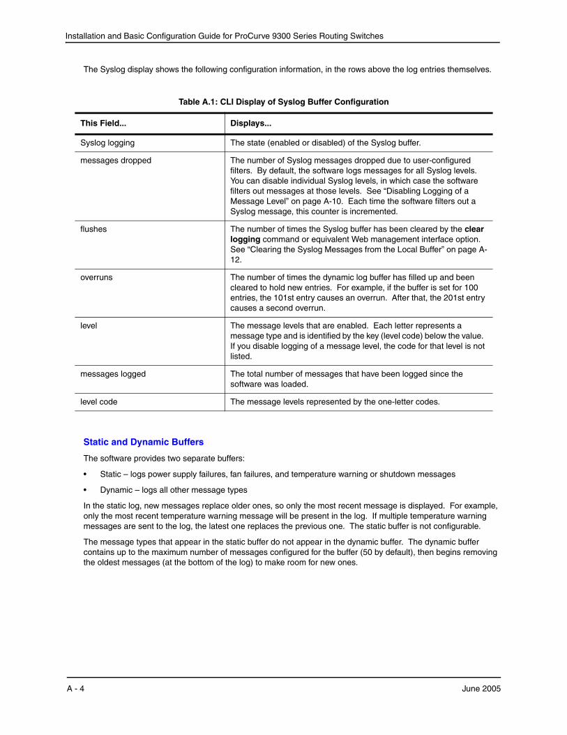
Installation and Basic Configuration Guide for ProCurve 9300 Series Routing Switches
The Syslog display shows the following configuration information, in the rows above the log entries themselves.
Table A.1: CLI Display of Syslog Buffer Configuration
This Field... Displays...
Syslog logging The state (enabled or disabled) of the Syslog buffer.
messages dropped The number of Syslog messages dropped due to user-configured filters. By default, the software logs messages for all Syslog levels. You can disable individual Syslog levels, in which case the software filters out messages at those levels. See “Disabling Logging of a Message Level” on page A-10. Each time the software filters out a Syslog message, this counter is incremented.
flushes The number of times the Syslog buffer has been cleared by the clear logging command or equivalent Web management interface option. See “Clearing the Syslog Messages from the Local Buffer” on page A-12.
overruns The number of times the dynamic log buffer has filled up and been cleared to hold new entries. For example, if the buffer is set for 100 entries, the 101st entry causes an overrun. After that, the 201st entry causes a second overrun.
level The message levels that are enabled. Each letter represents a message type and is identified by the key (level code) below the value. If you disable logging of a message level, the code for that level is not listed.
messages logged The total number of messages that have been logged since the software was loaded.
level code The message levels represented by the one-letter codes.
Static and Dynamic Buffers
The software provides two separate buffers:
• Static – logs power supply failures, fan failures, and temperature warning or shutdown messages
• Dynamic – logs all other message types
In the static log, new messages replace older ones, so only the most recent message is displayed. For example, only the most recent temperature warning message will be present in the log. If multiple temperature warning messages are sent to the log, the latest one replaces the previous one. The static buffer is not configurable.
The message types that appear in the static buffer do not appear in the dynamic buffer. The dynamic buffer contains up to the maximum number of messages configured for the buffer (50 by default), then begins removing the oldest messages (at the bottom of the log) to make room for new ones.
A - 4 June 2005

Using Syslog
The static and dynamic buffers are both displayed when you display the log.
ProCurveRS(config)# show logging
Syslog logging: enabled (0 messages dropped, 0 flushes, 0 overruns) Buffer logging: level ACDMEINW, 3 messages logged level code: A=alert C=critical D=debugging M=emergency E=error I=informational N=notification W=warning Static Log Buffer: Dec 15 19:04:14:A:Fan 1, fan on right connector, failed Dec 15 19:00:14:A:Fan 2, fan on left connector, failed
Dynamic Log Buffer (50 entries): Dec 15 18:46:17:I:Interface ethernet 1/4, state up Dec 15 18:45:21:I:Bridge topology change, vlan 4095, interface 4, changed state to forwarding Dec 15 18:45:15:I:Warm start
Notice that the static buffer contains two separate messages for fan failures. Each message of each type has its own buffer. Thus, if you replace fan 1 but for some reason that fan also fails, the software replaces the first message about the failure of fan 1 with the newer message. The software does not overwrite the message for fan 2, unless the software sends a newer message for fan 2.
When you clear log entries, you can selectively clear the static or dynamic buffer, or you can clear both. For example, to clear only the dynamic buffer, enter the following command at the Privileged EXEC level:
ProCurveRS# clear logging dynamic-buffer
Syntax: clear logging [dynamic-buffer | static-buffer]
You can specify dynamic-buffer to clear the dynamic buffer or static-buffer to clear the static buffer. If you do not specify a buffer, both buffers are cleared.
Time Stamps
The contents of the time stamp differ depending on whether you have set the time and date on the onboard system clock.
• If you have set the time and date on the onboard system clock, the date and time are shown in the following format: mm dd hh:mm:ss where:
• mm – abbreviation for the name of the month
• dd – day
• hh – hours
• mm – minutes
• ss – seconds
For example, “Oct 15 17:38:03” means October 15 at 5:38 PM and 3 seconds.
• If you have not set the time and date on the onboard system clock, the time stamp shows the amount of time that has passed since the device was booted, in the following format: <num>d<num>h<num>m<num>s where:
June 2005 A - 5
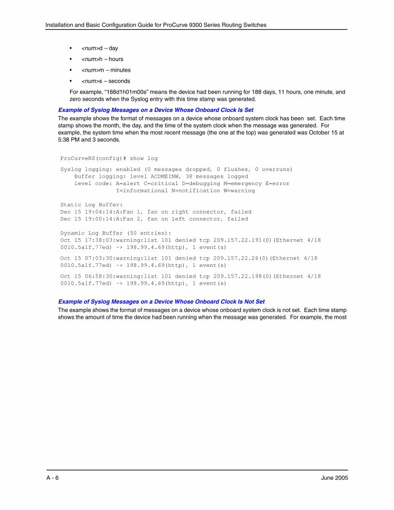
Installation and Basic Configuration Guide for ProCurve 9300 Series Routing Switches
• <num>d – day
• <num>h – hours
• <num>m – minutes
• <num>s – seconds
For example, “188d1h01m00s” means the device had been running for 188 days, 11 hours, one minute, and zero seconds when the Syslog entry with this time stamp was generated.
Example of Syslog Messages on a Device Whose Onboard Clock Is SetThe example shows the format of messages on a device whose onboard system clock has been set. Each time stamp shows the month, the day, and the time of the system clock when the message was generated. For example, the system time when the most recent message (the one at the top) was generated was October 15 at 5:38 PM and 3 seconds.
ProCurveRS(config)# show log
Syslog logging: enabled (0 messages dropped, 0 flushes, 0 overruns) Buffer logging: level ACDMEINW, 38 messages logged level code: A=alert C=critical D=debugging M=emergency E=error I=informational N=notification W=warning Static Log Buffer: Dec 15 19:04:14:A:Fan 1, fan on right connector, failed Dec 15 19:00:14:A:Fan 2, fan on left connector, failed Dynamic Log Buffer (50 entries): Oct 15 17:38:03:warning:list 101 denied tcp 209.157.22.191(0)(Ethernet 4/18 0010.5a1f.77ed) -> 198.99.4.69(http), 1 event(s)
Oct 15 07:03:30:warning:list 101 denied tcp 209.157.22.26(0)(Ethernet 4/18 0010.5a1f.77ed) -> 198.99.4.69(http), 1 event(s)
Oct 15 06:58:30:warning:list 101 denied tcp 209.157.22.198(0)(Ethernet 4/18 0010.5a1f.77ed) -> 198.99.4.69(http), 1 event(s)
Example of Syslog Messages on a Device Whose Onboard Clock Is Not SetThe example shows the format of messages on a device whose onboard system clock is not set. Each time stamp shows the amount of time the device had been running when the message was generated. For example, the most
A - 6 June 2005
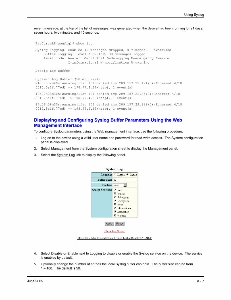
Using Syslog
recent message, at the top of the list of messages, was generated when the device had been running for 21 days, seven hours, two minutes, and 40 seconds.
ProCurveRS(config)# show log
Syslog logging: enabled (0 messages dropped, 0 flushes, 0 overruns) Buffer logging: level ACDMEINW, 38 messages logged level code: A=alert C=critical D=debugging M=emergency E=error I=informational N=notification W=warning Static Log Buffer: Dynamic Log Buffer (50 entries): 21d07h02m40s:warning:list 101 denied tcp 209.157.22.191(0)(Ethernet 4/18 0010.5a1f.77ed) -> 198.99.4.69(http), 1 event(s)
19d07h03m30s:warning:list 101 denied tcp 209.157.22.26(0)(Ethernet 4/18 0010.5a1f.77ed) -> 198.99.4.69(http), 1 event(s)
17d06h58m30s:warning:list 101 denied tcp 209.157.22.198(0)(Ethernet 4/18 0010.5a1f.77ed) -> 198.99.4.69(http), 1 event(s)
Displaying and Configuring Syslog Buffer Parameters Using the Web Management InterfaceTo configure Syslog parameters using the Web management interface, use the following procedure:
1. Log on to the device using a valid user name and password for read-write access. The System configuration panel is displayed.
2. Select Management from the System configuration sheet to display the Management panel.
3. Select the System Log link to display the following panel.
4. Select Disable or Enable next to Logging to disable or enable the Syslog service on the device. The service is enabled by default.
5. Optionally change the number of entries the local Syslog buffer can hold. The buffer size can be from 1 – 100. The default is 50.
June 2005 A - 7
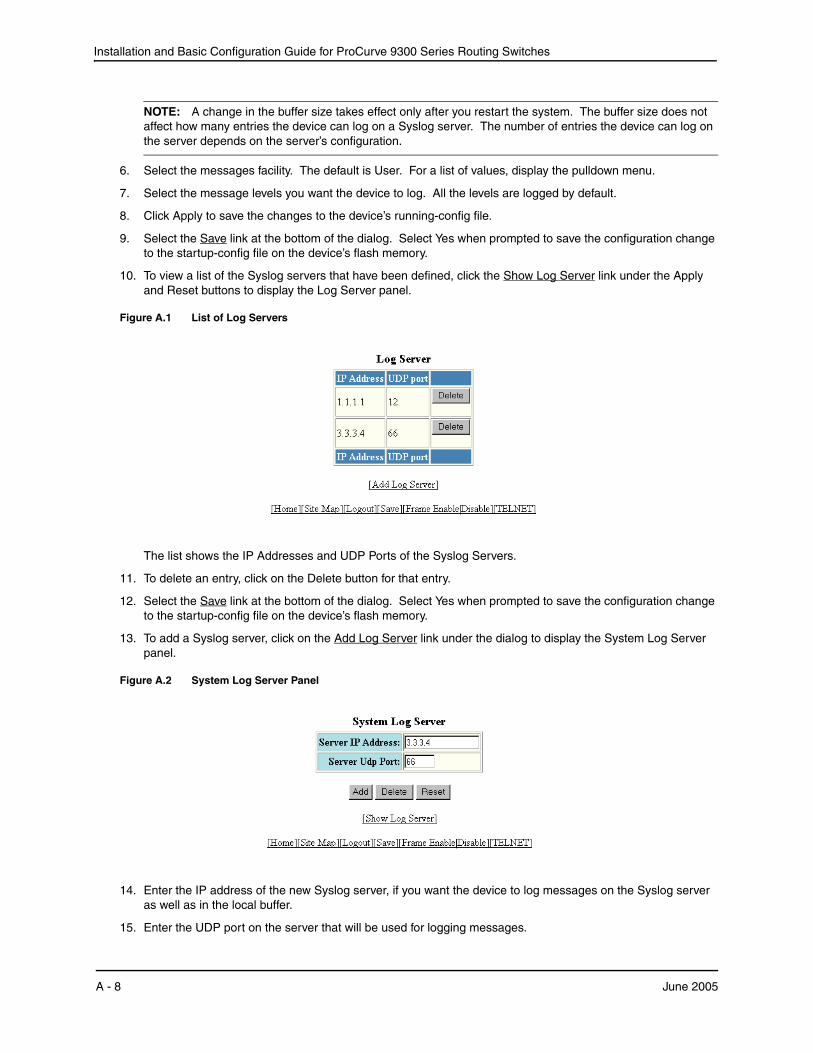
Installation and Basic Configuration Guide for ProCurve 9300 Series Routing Switches
NOTE: A change in the buffer size takes effect only after you restart the system. The buffer size does not affect how many entries the device can log on a Syslog server. The number of entries the device can log on the server depends on the server’s configuration.
6. Select the messages facility. The default is User. For a list of values, display the pulldown menu.
7. Select the message levels you want the device to log. All the levels are logged by default.
8. Click Apply to save the changes to the device’s running-config file.
9. Select the Save link at the bottom of the dialog. Select Yes when prompted to save the configuration change to the startup-config file on the device’s flash memory.
10. To view a list of the Syslog servers that have been defined, click the Show Log Server link under the Apply and Reset buttons to display the Log Server panel.
Figure A.1 List of Log Servers
The list shows the IP Addresses and UDP Ports of the Syslog Servers.
11. To delete an entry, click on the Delete button for that entry.
12. Select the Save link at the bottom of the dialog. Select Yes when prompted to save the configuration change to the startup-config file on the device’s flash memory.
13. To add a Syslog server, click on the Add Log Server link under the dialog to display the System Log Server panel.
Figure A.2 System Log Server Panel
14. Enter the IP address of the new Syslog server, if you want the device to log messages on the Syslog server as well as in the local buffer.
15. Enter the UDP port on the server that will be used for logging messages.
A - 8 June 2005

Using Syslog
16. Click on the Add button to add the server to the list. You can add up to six Syslog servers.
17. When you have finished, select the Save link at the bottom of the dialog. Select Yes when prompted to save the configuration change to the startup-config file on the device’s flash memory.
Disabling or Re-Enabling SyslogSyslog is enabled by default. To disable or re-enable it, use one of the following methods.
USING THE CLI
To disable it, enter the following command at the global CONFIG level:
ProCurveRS(config)# no logging on
Syntax: [no] logging on [<udp-port>]
The <udp-port> parameter specifies the application port used for the Syslog facility. The default is 514.
To re-enable logging, enter the following command:
ProCurveRS(config)# logging on
This command enables local Syslog logging with the following defaults:
• Messages of all severity levels (Emergencies – Debugging) are logged.
• Up to 50 messages are retained in the local Syslog buffer.
• No Syslog server is specified.
Specifying a Syslog ServerTo specify a Syslog server, use one of the following methods.
USING THE CLI
For software releases earlier than 07.7.00, enter a command such as the following:
ProCurveRS(config)# logging 10.0.0.99
For software releases 07.7.00 and later, enter a command such as the following:
ProCurveRS(config)# logging host 10.0.0.99
For backward compatibility, the software reads the old command syntax from the startup configuration, and converts it to the new command syntax in the running configuration.
Syntax: logging <ip-addr> | <server-name> (software releases earlier than 07.7.00)
Syntax: logging host <ip-addr> | <server-name> (software release 07.7.00 and later)
USING THE WEB MANAGEMENT INTERFACE
See the section “Displaying and Configuring Syslog Buffer Parameters Using the Web Management Interface” on page A-7.
NOTE: You can specify a server name only if you have already configured the DNS Resolver feature. See the “Configuring IP” chapter in the Advanced Configuration and Management Guide for ProCurve 9300/9400 Series Routing Switches.
Specifying an Additional Syslog ServerUSING THE CLI
To specify an additional Syslog server, enter the logging host <ip-addr> command again, as in the following example. You can specify up to six Syslog servers.
For software releases earlier than 07.7.00, enter a command such as the following:
June 2005 A - 9
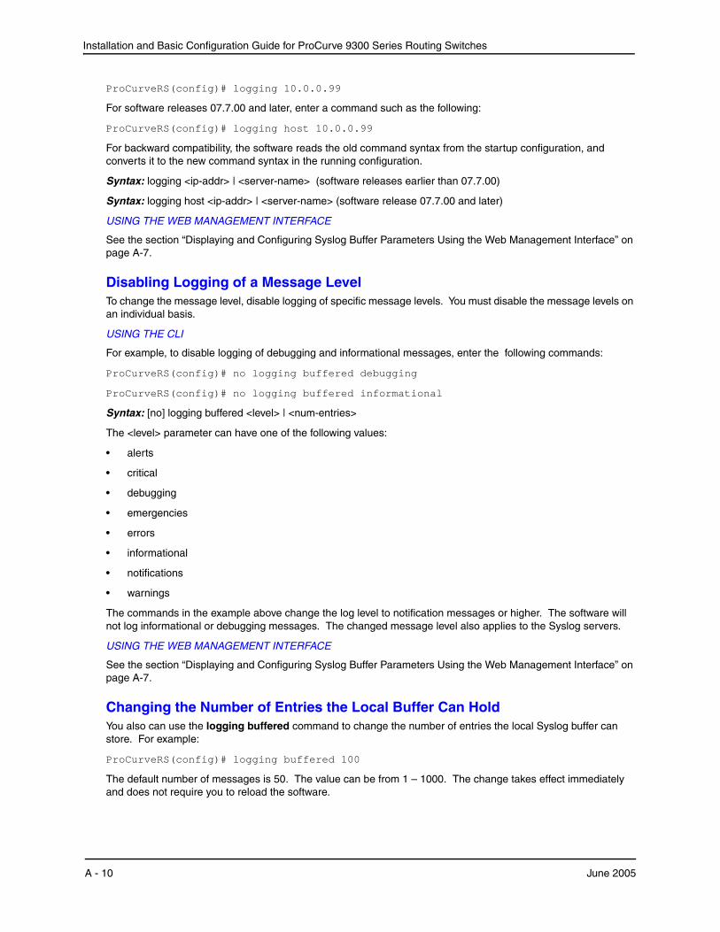
Installation and Basic Configuration Guide for ProCurve 9300 Series Routing Switches
ProCurveRS(config)# logging 10.0.0.99
For software releases 07.7.00 and later, enter a command such as the following:
ProCurveRS(config)# logging host 10.0.0.99
For backward compatibility, the software reads the old command syntax from the startup configuration, and converts it to the new command syntax in the running configuration.
Syntax: logging <ip-addr> | <server-name> (software releases earlier than 07.7.00)
Syntax: logging host <ip-addr> | <server-name> (software release 07.7.00 and later)
USING THE WEB MANAGEMENT INTERFACE
See the section “Displaying and Configuring Syslog Buffer Parameters Using the Web Management Interface” on page A-7.
Disabling Logging of a Message LevelTo change the message level, disable logging of specific message levels. You must disable the message levels on an individual basis.
USING THE CLI
For example, to disable logging of debugging and informational messages, enter the following commands:
ProCurveRS(config)# no logging buffered debugging
ProCurveRS(config)# no logging buffered informational
Syntax: [no] logging buffered <level> | <num-entries>
The <level> parameter can have one of the following values:
• alerts
• critical
• debugging
• emergencies
• errors
• informational
• notifications
• warnings
The commands in the example above change the log level to notification messages or higher. The software will not log informational or debugging messages. The changed message level also applies to the Syslog servers.
USING THE WEB MANAGEMENT INTERFACE
See the section “Displaying and Configuring Syslog Buffer Parameters Using the Web Management Interface” on page A-7.
Changing the Number of Entries the Local Buffer Can HoldYou also can use the logging buffered command to change the number of entries the local Syslog buffer can store. For example:
ProCurveRS(config)# logging buffered 100
The default number of messages is 50. The value can be from 1 – 1000. The change takes effect immediately and does not require you to reload the software.
A - 10 June 2005
Using Syslog
USING THE WEB MANAGEMENT INTERFACE
See the section “Displaying and Configuring Syslog Buffer Parameters Using the Web Management Interface” on page A-7.
NOTE: If you decrease the size of the buffer, the software clears the buffer before placing the change into effect. If you increase the size of the buffer, the software does not clear existing entries.
Changing the Log FacilityThe Syslog daemon on the Syslog server uses a facility to determine where to log the messages from the HP device. The default facility for messages the HP device sends to the Syslog server is “user”. You can change the facility using the following command.
NOTE: You can specify only one facility. If you configure the HP device to use two Syslog servers, the device uses the same facility on both servers.
ProCurveRS(config)# logging facility local0
Syntax: logging facility <facility-name>
The <facility-name> can be one of the following:
• kern – kernel messages
• user – random user-level messages
• mail – mail system
• daemon – system daemons
• auth – security/authorization messages
• syslog – messages generated internally by Syslog
• lpr – line printer subsystem
• news – netnews subsystem
• uucp – uucp subsystem
• sys9 – cron/at subsystem
• sys10 – reserved for system use
• sys11 – reserved for system use
• sys12 – reserved for system use
• sys13 – reserved for system use
• sys14 – reserved for system use
• cron – cron/at subsystem
• local0 – reserved for local use
• local1 – reserved for local use
• local2 – reserved for local use
• local3 – reserved for local use
• local4 – reserved for local use
• local5 – reserved for local use
• local6 – reserved for local use
• local7 – reserved for local use
June 2005 A - 11
Installation and Basic Configuration Guide for ProCurve 9300 Series Routing Switches
USING THE WEB MANAGEMENT INTERFACE
See the section “Displaying and Configuring Syslog Buffer Parameters Using the Web Management Interface” on page A-7.
Displaying the Interface Name in Syslog MessagesBy default, an interface’s slot number (if applicable) and port number are displayed when you display Syslog messages. If you want to display the name of the interface instead of its number, enter the following command:
ProCurveRS(config)# ip show-portname
This command is applied globally to all interfaces on Routing Switches.
Syntax: [no] Ip show-portname
When you display the messages in the Syslog, you see the interface name under the Dynamic Log Buffer section. The actual interface number is appended to the interface name. For example, if the interface name is "lab" and its port number is "2", you see "lab2" displayed as in the example below:
ProCurveRS# show logging
Syslog logging: enabled (0 messages dropped, 0 flushes, 0 overruns) Buffer logging: level ACDMEINW, 3 messages logged level code: A=alert C=critical D=debugging M=emergency E=error
I=informational N=notification W=warning
Static Log Buffer: Dec 15 19:04:14:A:Fan 1, fan on right connector, failed
Dynamic Log Buffer (50 entries): Dec 15 18:46:17:I:Interface ethernet Lab2, state up Dec 15 18:45:15:I:Warm start
Clearing the Syslog Messages from the Local BufferTo clear the Syslog messages stored in the HP device’s local buffer, use one of the following methods:
USING THE CLI
ProCurveRS# clear logging
Syntax: clear logging
USING THE WEB MANAGEMENT INTERFACE
To clear Syslog messages using the Web management interface, use the following procedure:
1. Log on to the device using a valid user name and password for read-write access. The System configuration panel is displayed.
2. Click on the plus sign next to Command in the tree view to display the command options.
3. Select the Clear link to display the Clear panel.
4. Click on the checkbox next to System Logging to place a checkmark in the box.
5. Click Apply to clear the log.
Displaying TCP/UDP Port Numbers in Syslog Messages The command ip show-acl-service-number allows you to change the display of TCP/UDP application information from the TCP/UDP well-known port name to the TCP/UDP port number. For example, entering the following command causes the HP device to display http (the well-known port name) instead of 80 (the port number) in the output of show commands, and other commands that contain application port information. By default, HP devices display TCP/UDP application information in named notation.
In this release, you can display TCP/UDP port number instead of their names in syslog messages by entering the following command:
A - 12 June 2005
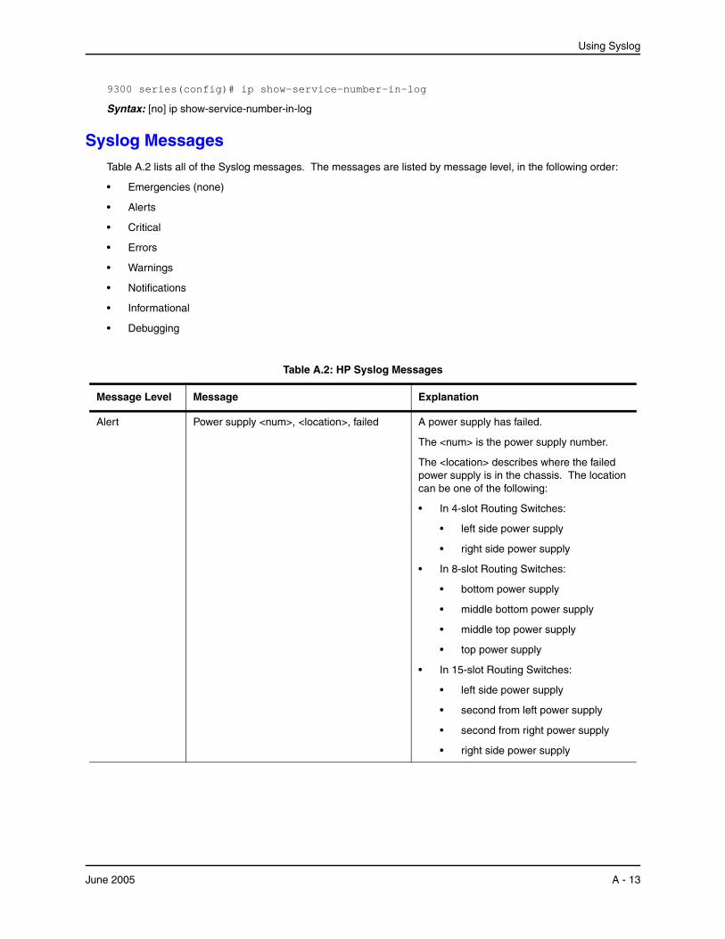
Using Syslog
9300 series(config)# ip show-service-number-in-log
Syntax: [no] ip show-service-number-in-log
Syslog MessagesTable A.2 lists all of the Syslog messages. The messages are listed by message level, in the following order:
• Emergencies (none)
• Alerts
• Critical
• Errors
• Warnings
• Notifications
• Informational
• Debugging
Table A.2: HP Syslog Messages
Message Level Message Explanation
Alert Power supply <num>, <location>, failed A power supply has failed.
The <num> is the power supply number.
The <location> describes where the failed power supply is in the chassis. The location can be one of the following:
• In 4-slot Routing Switches:
• left side power supply
• right side power supply
• In 8-slot Routing Switches:
• bottom power supply
• middle bottom power supply
• middle top power supply
• top power supply
• In 15-slot Routing Switches:
• left side power supply
• second from left power supply
• second from right power supply
• right side power supply
June 2005 A - 13
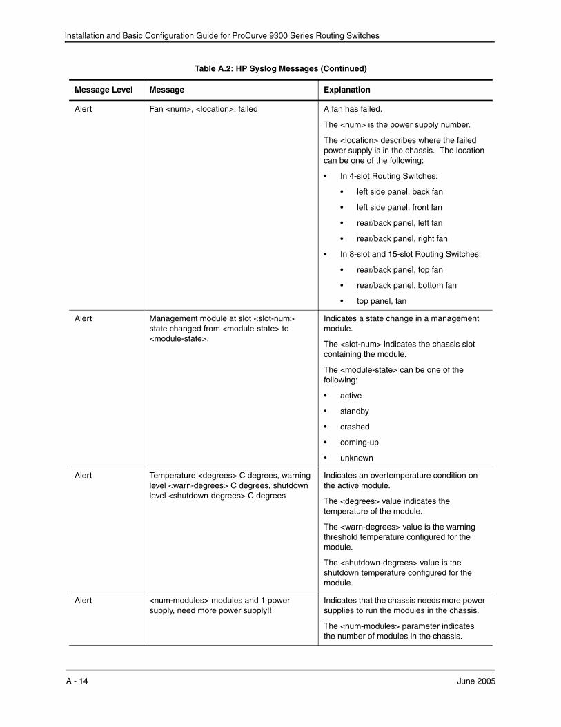
Installation and Basic Configuration Guide for ProCurve 9300 Series Routing Switches
Alert Fan <num>, <location>, failed A fan has failed.
The <num> is the power supply number.
The <location> describes where the failed power supply is in the chassis. The location can be one of the following:
• In 4-slot Routing Switches:
• left side panel, back fan
• left side panel, front fan
• rear/back panel, left fan
• rear/back panel, right fan
• In 8-slot and 15-slot Routing Switches:
• rear/back panel, top fan
• rear/back panel, bottom fan
• top panel, fan
Alert Management module at slot <slot-num> state changed from <module-state> to <module-state>.
Indicates a state change in a management module.
The <slot-num> indicates the chassis slot containing the module.
The <module-state> can be one of the following:
• active
• standby
• crashed
• coming-up
• unknown
Alert Temperature <degrees> C degrees, warning level <warn-degrees> C degrees, shutdown level <shutdown-degrees> C degrees
Indicates an overtemperature condition on the active module.
The <degrees> value indicates the temperature of the module.
The <warn-degrees> value is the warning threshold temperature configured for the module.
The <shutdown-degrees> value is the shutdown temperature configured for the module.
Alert <num-modules> modules and 1 power supply, need more power supply!!
Indicates that the chassis needs more power supplies to run the modules in the chassis.
The <num-modules> parameter indicates the number of modules in the chassis.
Table A.2: HP Syslog Messages (Continued)
Message Level Message Explanation
A - 14 June 2005
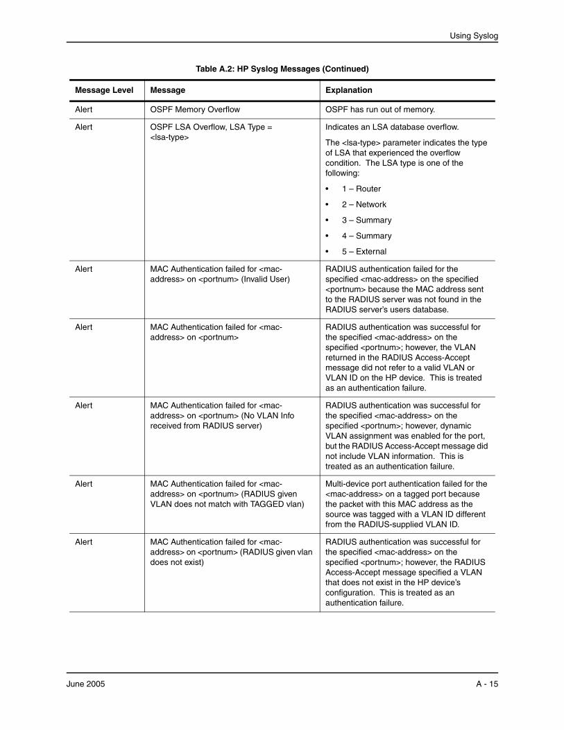
Using Syslog
Alert OSPF Memory Overflow OSPF has run out of memory.
Alert OSPF LSA Overflow, LSA Type = <lsa-type>
Indicates an LSA database overflow.
The <lsa-type> parameter indicates the type of LSA that experienced the overflow condition. The LSA type is one of the following:
• 1 – Router
• 2 – Network
• 3 – Summary
• 4 – Summary
• 5 – External
Alert MAC Authentication failed for <mac-address> on <portnum> (Invalid User)
RADIUS authentication failed for the specified <mac-address> on the specified <portnum> because the MAC address sent to the RADIUS server was not found in the RADIUS server’s users database.
Alert MAC Authentication failed for <mac-address> on <portnum>
RADIUS authentication was successful for the specified <mac-address> on the specified <portnum>; however, the VLAN returned in the RADIUS Access-Accept message did not refer to a valid VLAN or VLAN ID on the HP device. This is treated as an authentication failure.
Alert MAC Authentication failed for <mac-address> on <portnum> (No VLAN Info received from RADIUS server)
RADIUS authentication was successful for the specified <mac-address> on the specified <portnum>; however, dynamic VLAN assignment was enabled for the port, but the RADIUS Access-Accept message did not include VLAN information. This is treated as an authentication failure.
Alert MAC Authentication failed for <mac-address> on <portnum> (RADIUS given VLAN does not match with TAGGED vlan)
Multi-device port authentication failed for the <mac-address> on a tagged port because the packet with this MAC address as the source was tagged with a VLAN ID different from the RADIUS-supplied VLAN ID.
Alert MAC Authentication failed for <mac-address> on <portnum> (RADIUS given vlan does not exist)
RADIUS authentication was successful for the specified <mac-address> on the specified <portnum>; however, the RADIUS Access-Accept message specified a VLAN that does not exist in the HP device’s configuration. This is treated as an authentication failure.
Table A.2: HP Syslog Messages (Continued)
Message Level Message Explanation
June 2005 A - 15
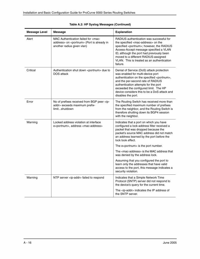
Installation and Basic Configuration Guide for ProCurve 9300 Series Routing Switches
Alert MAC Authentication failed for <mac-address> on <portnum> (Port is already in another radius given vlan)
RADIUS authentication was successful for the specified <mac-address> on the specified <portnum>; however, the RADIUS Access-Accept message specified a VLAN ID, although the port had previously been moved to a different RADIUS-assigned VLAN. This is treated as an authentication failure.
Critical Authentication shut down <portnum> due to DOS attack
Denial of Service (DoS) attack protection was enabled for multi-device port authentication on the specified <portnum>, and the per-second rate of RADIUS authentication attempts for the port exceeded the configured limit. The HP device considers this to be a DoS attack and disables the port.
Error No of prefixes received from BGP peer <ip-addr> exceeds maximum prefix-limit...shutdown
The Routing Switch has received more than the specified maximum number of prefixes from the neighbor, and the Routing Switch is therefore shutting down its BGP4 session with the neighbor.
Warning Locked address violation at interface e<portnum>, address <mac-address>
Indicates that a port on which you have configured a lock-address filter received a packet that was dropped because the packet’s source MAC address did not match an address learned by the port before the lock took effect.
The e<portnum> is the port number.
The <mac-address> is the MAC address that was denied by the address lock.
Assuming that you configured the port to learn only the addresses that have valid access to the port, this message indicates a security violation.
Warning NTP server <ip-addr> failed to respond Indicates that a Simple Network Time Protocol (SNTP) server did not respond to the device’s query for the current time.
The <ip-addr> indicates the IP address of the SNTP server.
Table A.2: HP Syslog Messages (Continued)
Message Level Message Explanation
A - 16 June 2005

Using Syslog
Warning Dup IP <ip-addr> detected, sent from MAC <mac-addr> interface <portnum>
Indicates that the HP device received a packet from another device on the network with an IP address that is also configured on the HP device.
The <ip-addr> is the duplicate IP address.
The <mac-addr> is the MAC address of the device with the duplicate IP address.
The <portnum> is the HP port that received the packet with the duplicate IP address. The address is the packet’s source IP address.
Warning mac filter group denied packets on port <portnum> src macaddr <mac-addr>, <num> packets
Indicates that a Layer 2 MAC filter group configured on a port has denied packets.
The <portnum> is the port on which the packets were denied.
The <mac-addr> is the source MAC address of the denied packets.
The <num> indicates how many packets matching the values above were dropped during the five-minute interval represented by the log entry.
Warning list <acl-num> denied <ip-proto> <src-ip-addr> (<src-tcp/udp-port>) (Ethernet <portnum> <mac-addr>) -> <dst-ip-addr> (<dst-tcp/udp-port>), 1 event(s)
Indicates that an Access Control List (ACL) denied (dropped) packets.
The <acl-num> indicates the ACL number. Numbers 1 – 99 indicate standard ACLs. Numbers 100 – 199 indicate extended ACLs.
The <ip-proto> indicates the IP protocol of the denied packets.
The <src-ip-addr> is the source IP address of the denied packets.
The <src-tcp/udp-port> is the source TCP or UDP port, if applicable, of the denied packets.
The <portnum> indicates the port number on which the packet was denied.
The <mac-addr> indicates the source MAC address of the denied packets.
The <dst-ip-addr> indicates the destination IP address of the denied packets.
The <dst-tcp/udp-port> indicates the destination TCP or UDP port number, if applicable, of the denied packets.
Table A.2: HP Syslog Messages (Continued)
Message Level Message Explanation
June 2005 A - 17
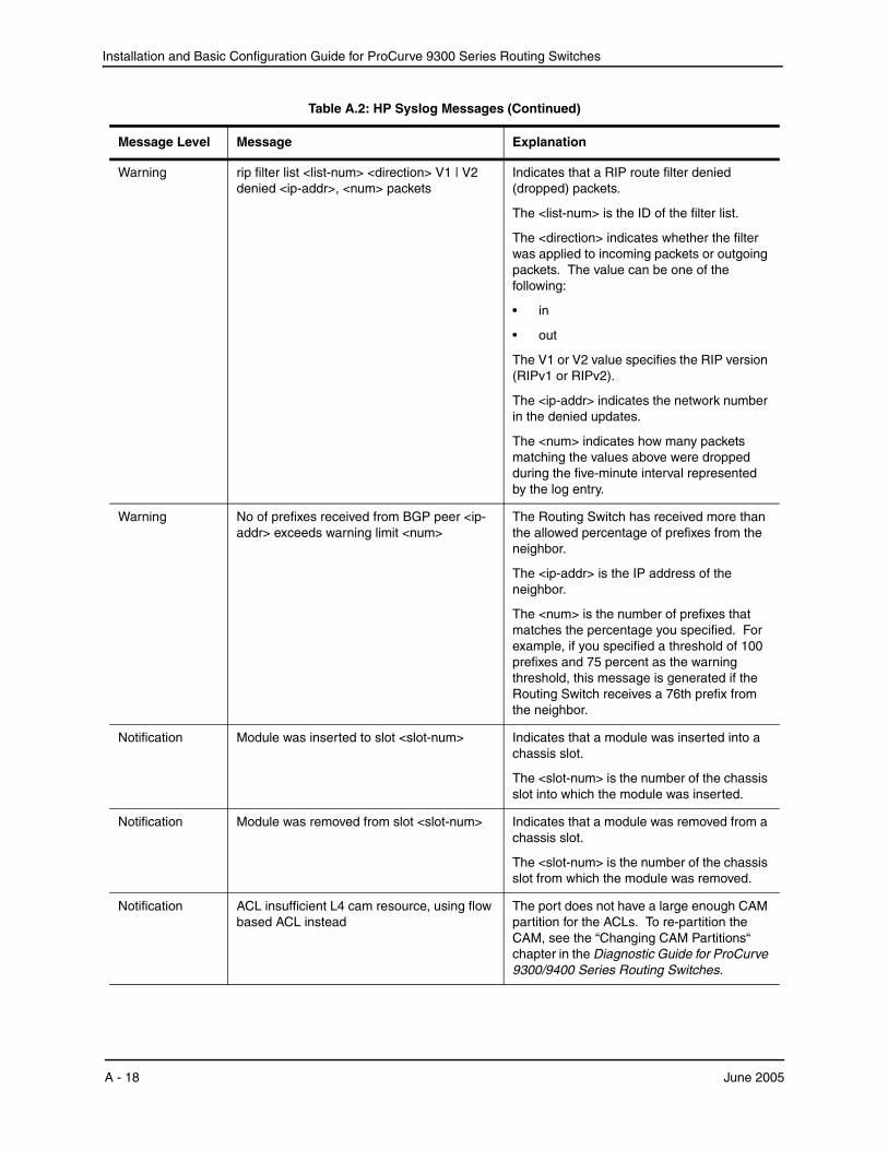
Installation and Basic Configuration Guide for ProCurve 9300 Series Routing Switches
Warning rip filter list <list-num> <direction> V1 | V2 denied <ip-addr>, <num> packets
Indicates that a RIP route filter denied (dropped) packets.
The <list-num> is the ID of the filter list.
The <direction> indicates whether the filter was applied to incoming packets or outgoing packets. The value can be one of the following:
• in
• out
The V1 or V2 value specifies the RIP version (RIPv1 or RIPv2).
The <ip-addr> indicates the network number in the denied updates.
The <num> indicates how many packets matching the values above were dropped during the five-minute interval represented by the log entry.
Warning No of prefixes received from BGP peer <ip-addr> exceeds warning limit <num>
The Routing Switch has received more than the allowed percentage of prefixes from the neighbor.
The <ip-addr> is the IP address of the neighbor.
The <num> is the number of prefixes that matches the percentage you specified. For example, if you specified a threshold of 100 prefixes and 75 percent as the warning threshold, this message is generated if the Routing Switch receives a 76th prefix from the neighbor.
Notification Module was inserted to slot <slot-num> Indicates that a module was inserted into a chassis slot.
The <slot-num> is the number of the chassis slot into which the module was inserted.
Notification Module was removed from slot <slot-num> Indicates that a module was removed from a chassis slot.
The <slot-num> is the number of the chassis slot from which the module was removed.
Notification ACL insufficient L4 cam resource, using flow based ACL instead
The port does not have a large enough CAM partition for the ACLs. To re-partition the CAM, see the “Changing CAM Partitions“ chapter in the Diagnostic Guide for ProCurve 9300/9400 Series Routing Switches.
Table A.2: HP Syslog Messages (Continued)
Message Level Message Explanation
A - 18 June 2005

Using Syslog
Notification OSPF interface state changed, rid <router-id>, intf addr <ip-addr>, state <ospf-state>
Indicates that the state of an OSPF interface has changed.
The <router-id> is the router ID of the HP device.
The <ip-addr> is the interface’s IP address.
The <ospf-state> indicates the state to which the interface has changed and can be one of the following:
• down
• loopback
• waiting
• point-to-point
• designated router
• backup designated router
• other designated router
• unknown
Notification OSPF virtual intf state changed, rid <router-id>, area <area-id>, nbr <ip-addr>, state <ospf-state>
Indicates that the state of an OSPF virtual routing interface has changed.
The <router-id> is the router ID of the router the interface is on.
The <area-id> is the area the interface is in.
The <ip-addr> is the IP address of the OSPF neighbor.
The <ospf-state> indicates the state to which the interface has changed and can be one of the following:
• down
• loopback
• waiting
• point-to-point
• designated router
• backup designated router
• other designated router
• unknown
Table A.2: HP Syslog Messages (Continued)
Message Level Message Explanation
June 2005 A - 19
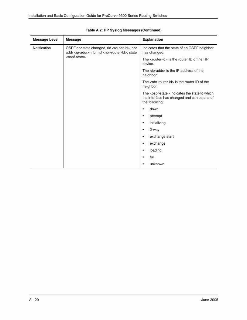
Installation and Basic Configuration Guide for ProCurve 9300 Series Routing Switches
Notification OSPF nbr state changed, rid <router-id>, nbr addr <ip-addr>, nbr rid <nbr-router-Id>, state <ospf-state>
Indicates that the state of an OSPF neighbor has changed.
The <router-id> is the router ID of the HP device.
The <ip-addr> is the IP address of the neighbor.
The <nbr-router-id> is the router ID of the neighbor.
The <ospf-state> indicates the state to which the interface has changed and can be one of the following:
• down
• attempt
• initializing
• 2-way
• exchange start
• exchange
• loading
• full
• unknown
Table A.2: HP Syslog Messages (Continued)
Message Level Message Explanation
A - 20 June 2005
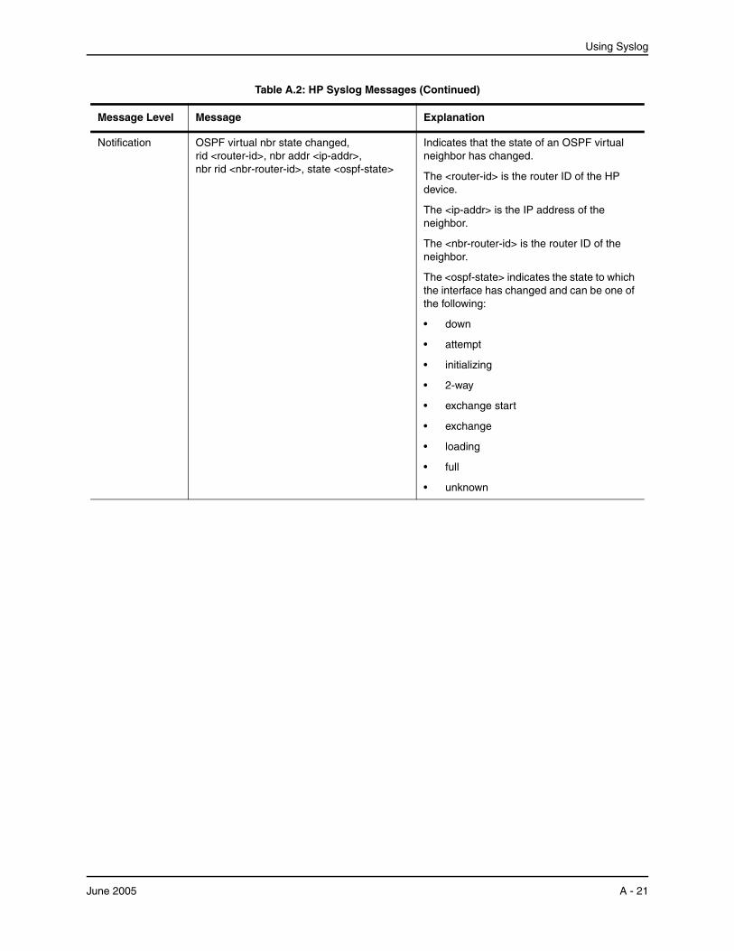
Using Syslog
Notification OSPF virtual nbr state changed, rid <router-id>, nbr addr <ip-addr>, nbr rid <nbr-router-id>, state <ospf-state>
Indicates that the state of an OSPF virtual neighbor has changed.
The <router-id> is the router ID of the HP device.
The <ip-addr> is the IP address of the neighbor.
The <nbr-router-id> is the router ID of the neighbor.
The <ospf-state> indicates the state to which the interface has changed and can be one of the following:
• down
• attempt
• initializing
• 2-way
• exchange start
• exchange
• loading
• full
• unknown
Table A.2: HP Syslog Messages (Continued)
Message Level Message Explanation
June 2005 A - 21
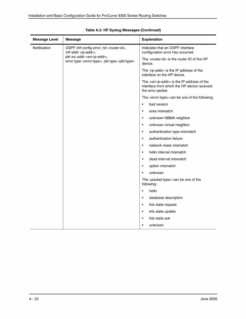
Installation and Basic Configuration Guide for ProCurve 9300 Series Routing Switches
Notification OSPF intf config error, rid <router-id>, intf addr <ip-addr>, pkt src addr <src-ip-addr>, error type <error-type>, pkt type <pkt-type>
Indicates that an OSPF interface configuration error has occurred.
The <router-id> is the router ID of the HP device.
The <ip-addr> is the IP address of the interface on the HP device.
The <src-ip-addr> is the IP address of the interface from which the HP device received the error packet.
The <error-type> can be one of the following:
• bad version
• area mismatch
• unknown NBMA neighbor
• unknown virtual neighbor
• authentication type mismatch
• authentication failure
• network mask mismatch
• hello interval mismatch
• dead interval mismatch
• option mismatch
• unknown
The <packet-type> can be one of the following:
• hello
• database description
• link state request
• link state update
• link state ack
• unknown
Table A.2: HP Syslog Messages (Continued)
Message Level Message Explanation
A - 22 June 2005

Using Syslog
Notification OSPF virtual intf config error, rid <router-id>, intf addr <ip-addr>, pkt src addr <src-ip-addr>, error type <error-type>, pkt type <pkt-type>
Indicates that an OSPF virtual routing interface configuration error has occurred.
The <router-id> is the router ID of the HP device.
The <ip-addr> is the IP address of the interface on the HP device.
The <src-ip-addr> is the IP address of the interface from which the HP device received the error packet.
The <error-type> can be one of the following:
• bad version
• area mismatch
• unknown NBMA neighbor
• unknown virtual neighbor
• authentication type mismatch
• authentication failure
• network mask mismatch
• hello interval mismatch
• dead interval mismatch
• option mismatch
• unknown
The <packet-type> can be one of the following:
• hello
• database description
• link state request
• link state update
• link state ack
• unknown
Table A.2: HP Syslog Messages (Continued)
Message Level Message Explanation
June 2005 A - 23
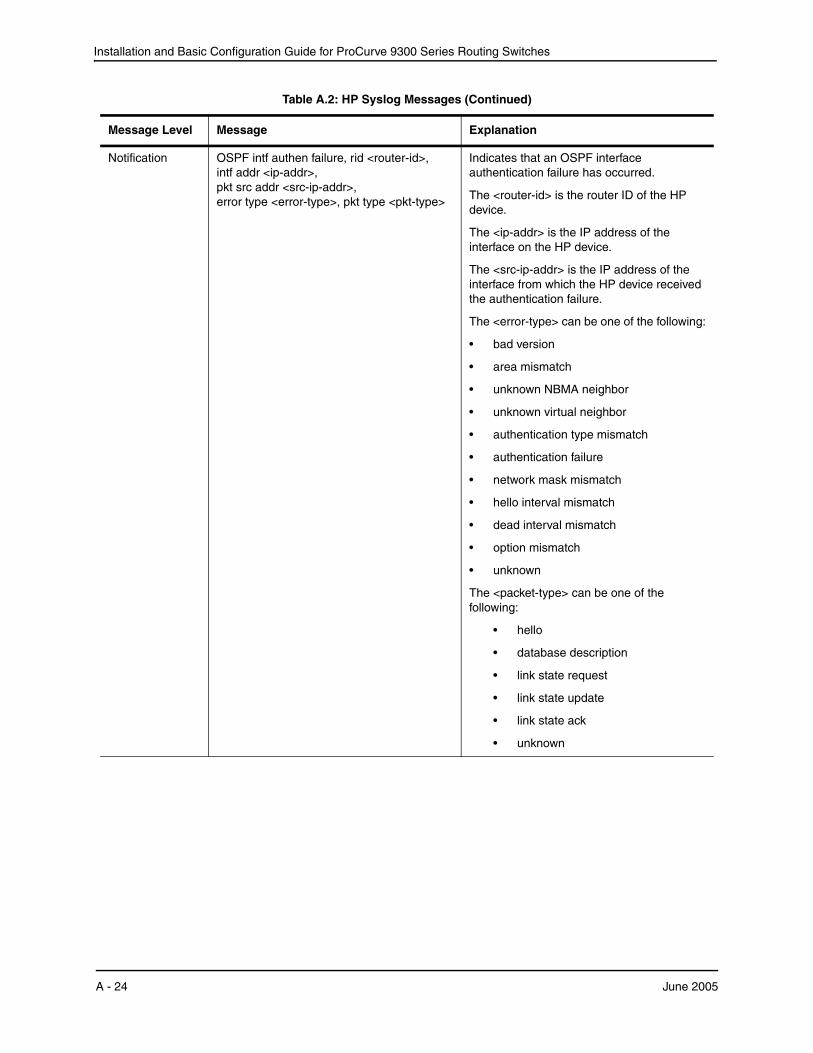
Installation and Basic Configuration Guide for ProCurve 9300 Series Routing Switches
Notification OSPF intf authen failure, rid <router-id>, intf addr <ip-addr>, pkt src addr <src-ip-addr>, error type <error-type>, pkt type <pkt-type>
Indicates that an OSPF interface authentication failure has occurred.
The <router-id> is the router ID of the HP device.
The <ip-addr> is the IP address of the interface on the HP device.
The <src-ip-addr> is the IP address of the interface from which the HP device received the authentication failure.
The <error-type> can be one of the following:
• bad version
• area mismatch
• unknown NBMA neighbor
• unknown virtual neighbor
• authentication type mismatch
• authentication failure
• network mask mismatch
• hello interval mismatch
• dead interval mismatch
• option mismatch
• unknown
The <packet-type> can be one of the following:
• hello
• database description
• link state request
• link state update
• link state ack
• unknown
Table A.2: HP Syslog Messages (Continued)
Message Level Message Explanation
A - 24 June 2005
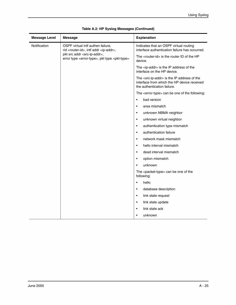
Using Syslog
Notification OSPF virtual intf authen failure, rid <router-id>, intf addr <ip-addr>, pkt src addr <src-ip-addr>, error type <error-type>, pkt type <pkt-type>
Indicates that an OSPF virtual routing interface authentication failure has occurred.
The <router-id> is the router ID of the HP device.
The <ip-addr> is the IP address of the interface on the HP device.
The <src-ip-addr> is the IP address of the interface from which the HP device received the authentication failure.
The <error-type> can be one of the following:
• bad version
• area mismatch
• unknown NBMA neighbor
• unknown virtual neighbor
• authentication type mismatch
• authentication failure
• network mask mismatch
• hello interval mismatch
• dead interval mismatch
• option mismatch
• unknown
The <packet-type> can be one of the following:
• hello
• database description
• link state request
• link state update
• link state ack
• unknown
Table A.2: HP Syslog Messages (Continued)
Message Level Message Explanation
June 2005 A - 25
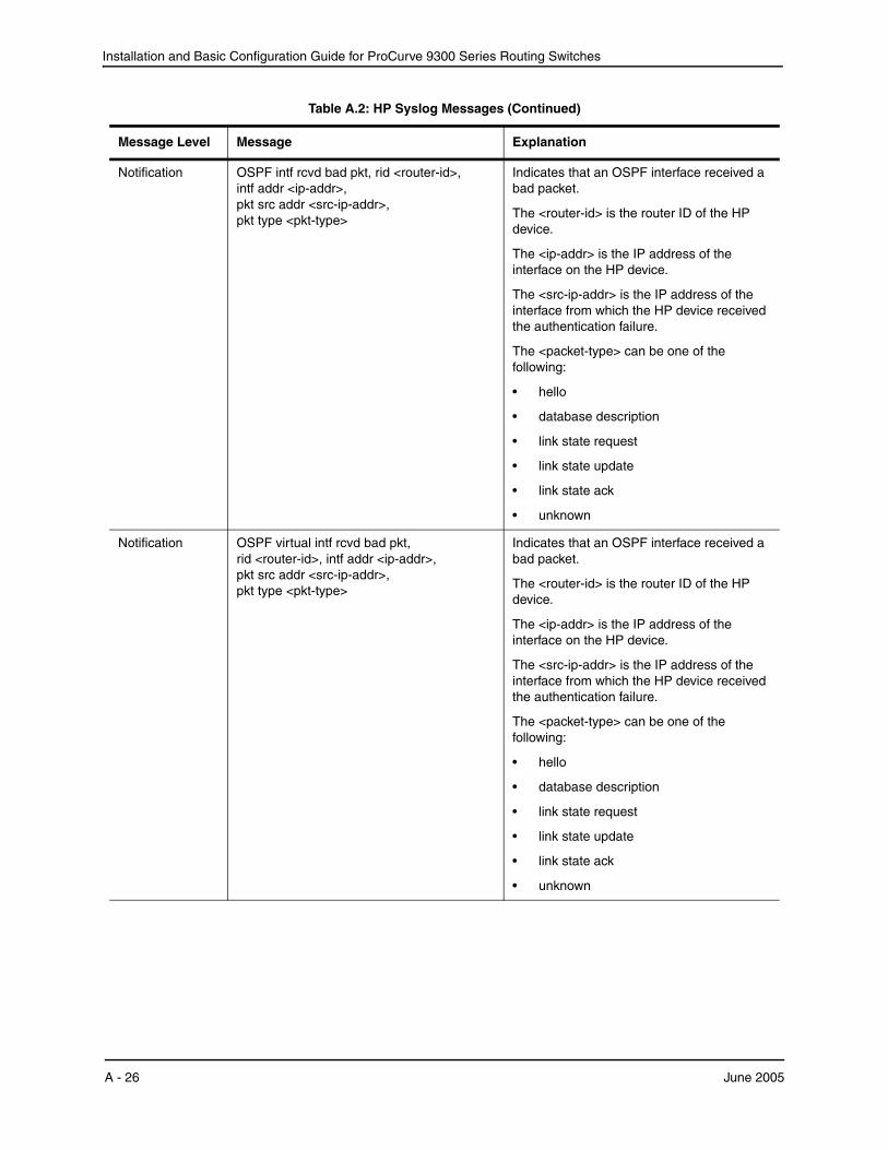
Installation and Basic Configuration Guide for ProCurve 9300 Series Routing Switches
Notification OSPF intf rcvd bad pkt, rid <router-id>, intf addr <ip-addr>, pkt src addr <src-ip-addr>, pkt type <pkt-type>
Indicates that an OSPF interface received a bad packet.
The <router-id> is the router ID of the HP device.
The <ip-addr> is the IP address of the interface on the HP device.
The <src-ip-addr> is the IP address of the interface from which the HP device received the authentication failure.
The <packet-type> can be one of the following:
• hello
• database description
• link state request
• link state update
• link state ack
• unknown
Notification OSPF virtual intf rcvd bad pkt, rid <router-id>, intf addr <ip-addr>, pkt src addr <src-ip-addr>, pkt type <pkt-type>
Indicates that an OSPF interface received a bad packet.
The <router-id> is the router ID of the HP device.
The <ip-addr> is the IP address of the interface on the HP device.
The <src-ip-addr> is the IP address of the interface from which the HP device received the authentication failure.
The <packet-type> can be one of the following:
• hello
• database description
• link state request
• link state update
• link state ack
• unknown
Table A.2: HP Syslog Messages (Continued)
Message Level Message Explanation
A - 26 June 2005

Using Syslog
Notification OSPF intf retransmit, rid <router-id>, intf addr <ip-addr>, nbr rid <nbr-router-id>, pkt type is <pkt-type>, LSA type <lsa-type>, LSA id <lsa-id>, LSA rid <lsa-router-id>
An OSPF interface on the HP device has retransmitted a Link State Advertisement (LSA).
The <router-id> is the router ID of the HP device.
The <ip-addr> is the IP address of the interface on the HP device.
The <nbr-router-id> is the router ID of the neighbor Routing Switch.
The <packet-type> can be one of the following:
• hello
• database description
• link state request
• link state update
• link state ack
• unknown
The <lsa-type> is the type of LSA.
The <lsa-id> is the LSA ID.
The <lsa-router-id> is the LSA router ID.
Table A.2: HP Syslog Messages (Continued)
Message Level Message Explanation
June 2005 A - 27
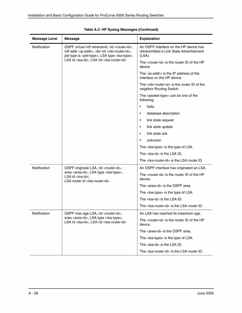
Installation and Basic Configuration Guide for ProCurve 9300 Series Routing Switches
Notification OSPF virtual intf retransmit, rid <router-id>, intf addr <ip-addr>, nbr rid <nbr-router-id>, pkt type is <pkt-type>, LSA type <lsa-type>, LSA id <lsa-id>, LSA rid <lsa-router-id>
An OSPF interface on the HP device has retransmitted a Link State Advertisement (LSA).
The <router-id> is the router ID of the HP device.
The <ip-addr> is the IP address of the interface on the HP device.
The <nbr-router-id> is the router ID of the neighbor Routing Switch.
The <packet-type> can be one of the following:
• hello
• database description
• link state request
• link state update
• link state ack
• unknown
The <lsa-type> is the type of LSA.
The <lsa-id> is the LSA ID.
The <lsa-router-id> is the LSA router ID.
Notification OSPF originate LSA, rid <router-id>, area <area-id>, LSA type <lsa-type>, LSA id <lsa-id>, LSA router id <lsa-router-id>
An OSPF interface has originated an LSA.
The <router-id> is the router ID of the HP device.
The <area-id> is the OSPF area.
The <lsa-type> is the type of LSA.
The <lsa-id> is the LSA ID.
The <lsa-router-id> is the LSA router ID.
Notification OSPF max age LSA, rid <router-id>, area <area-id>, LSA type <lsa-type>, LSA id <lsa-id>, LSA rid <lsa-router-id>
An LSA has reached its maximum age.
The <router-id> is the router ID of the HP device.
The <area-id> is the OSPF area.
The <lsa-type> is the type of LSA.
The <lsa-id> is the LSA ID.
The <lsa-router-id> is the LSA router ID.
Table A.2: HP Syslog Messages (Continued)
Message Level Message Explanation
A - 28 June 2005
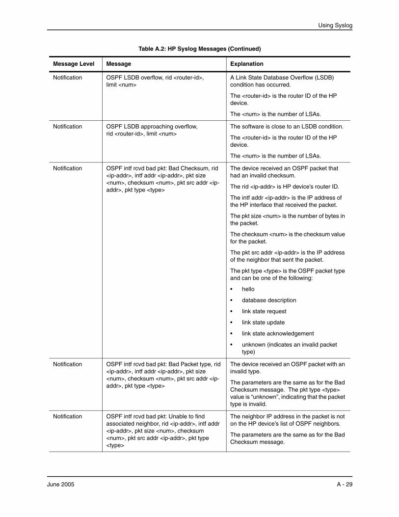
Using Syslog
Notification OSPF LSDB overflow, rid <router-id>, limit <num>
A Link State Database Overflow (LSDB) condition has occurred.
The <router-id> is the router ID of the HP device.
The <num> is the number of LSAs.
Notification OSPF LSDB approaching overflow, rid <router-id>, limit <num>
The software is close to an LSDB condition.
The <router-id> is the router ID of the HP device.
The <num> is the number of LSAs.
Notification OSPF intf rcvd bad pkt: Bad Checksum, rid <ip-addr>, intf addr <ip-addr>, pkt size <num>, checksum <num>, pkt src addr <ip-addr>, pkt type <type>
The device received an OSPF packet that had an invalid checksum.
The rid <ip-addr> is HP device’s router ID.
The intf addr <ip-addr> is the IP address of the HP interface that received the packet.
The pkt size <num> is the number of bytes in the packet.
The checksum <num> is the checksum value for the packet.
The pkt src addr <ip-addr> is the IP address of the neighbor that sent the packet.
The pkt type <type> is the OSPF packet type and can be one of the following:
• hello
• database description
• link state request
• link state update
• link state acknowledgement
• unknown (indicates an invalid packet type)
Notification OSPF intf rcvd bad pkt: Bad Packet type, rid <ip-addr>, intf addr <ip-addr>, pkt size <num>, checksum <num>, pkt src addr <ip-addr>, pkt type <type>
The device received an OSPF packet with an invalid type.
The parameters are the same as for the Bad Checksum message. The pkt type <type> value is “unknown”, indicating that the packet type is invalid.
Notification OSPF intf rcvd bad pkt: Unable to find associated neighbor, rid <ip-addr>, intf addr <ip-addr>, pkt size <num>, checksum <num>, pkt src addr <ip-addr>, pkt type <type>
The neighbor IP address in the packet is not on the HP device’s list of OSPF neighbors.
The parameters are the same as for the Bad Checksum message.
Table A.2: HP Syslog Messages (Continued)
Message Level Message Explanation
June 2005 A - 29
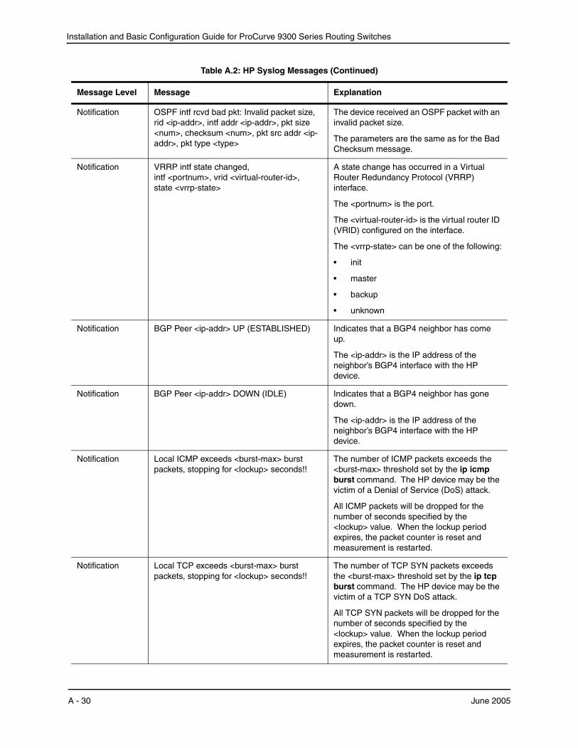
Installation and Basic Configuration Guide for ProCurve 9300 Series Routing Switches
Notification OSPF intf rcvd bad pkt: Invalid packet size, rid <ip-addr>, intf addr <ip-addr>, pkt size <num>, checksum <num>, pkt src addr <ip-addr>, pkt type <type>
The device received an OSPF packet with an invalid packet size.
The parameters are the same as for the Bad Checksum message.
Notification VRRP intf state changed, intf <portnum>, vrid <virtual-router-id>, state <vrrp-state>
A state change has occurred in a Virtual Router Redundancy Protocol (VRRP) interface.
The <portnum> is the port.
The <virtual-router-id> is the virtual router ID (VRID) configured on the interface.
The <vrrp-state> can be one of the following:
• init
• master
• backup
• unknown
Notification BGP Peer <ip-addr> UP (ESTABLISHED) Indicates that a BGP4 neighbor has come up.
The <ip-addr> is the IP address of the neighbor’s BGP4 interface with the HP device.
Notification BGP Peer <ip-addr> DOWN (IDLE) Indicates that a BGP4 neighbor has gone down.
The <ip-addr> is the IP address of the neighbor’s BGP4 interface with the HP device.
Notification Local ICMP exceeds <burst-max> burst packets, stopping for <lockup> seconds!!
The number of ICMP packets exceeds the <burst-max> threshold set by the ip icmp burst command. The HP device may be the victim of a Denial of Service (DoS) attack.
All ICMP packets will be dropped for the number of seconds specified by the <lockup> value. When the lockup period expires, the packet counter is reset and measurement is restarted.
Notification Local TCP exceeds <burst-max> burst packets, stopping for <lockup> seconds!!
The number of TCP SYN packets exceeds the <burst-max> threshold set by the ip tcp burst command. The HP device may be the victim of a TCP SYN DoS attack.
All TCP SYN packets will be dropped for the number of seconds specified by the <lockup> value. When the lockup period expires, the packet counter is reset and measurement is restarted.
Table A.2: HP Syslog Messages (Continued)
Message Level Message Explanation
A - 30 June 2005

Using Syslog
Notification Transit ICMP in interface <portnum> exceeds <num> burst packets, stopping for <num> seconds!!
Threshold parameters for ICMP transit (through) traffic have been configured on an interface, and the maximum burst size for ICMP packets on the interface has been exceeded.
The <portnum> is the port number.
The first <num> is the maximum burst size (maximum number of packets allowed).
The second <num> is the number of seconds during which additional ICMP packets will be blocked on the interface.
Note: This message can occur in response to an attempted Smurf attack.
Notification Local TCP exceeds <num> burst packets, stopping for <num> seconds!!
Threshold parameters for local TCP traffic on the device have been configured, and the maximum burst size for TCP packets has been exceeded.
The first <num> is the maximum burst size (maximum number of packets allowed).
The second <num> is the number of seconds during which additional TCP packets will be blocked on the device.
Note: This message can occur in response to an attempted TCP SYN attack.
Notification Transit TCP in interface <portnum> exceeds <num> burst packets, stopping for <num> seconds!!
Threshold parameters for TCP transit (through) traffic have been configured on an interface, and the maximum burst size for TCP packets on the interface has been exceeded.
The <portnum> is the port number.
The first <num> is the maximum burst size (maximum number of packets allowed).
The second <num> is the number of seconds during which additional TCP packets will be blocked on the interface.
Note: This message can occur in response to an attempted TCP SYN attack.
Notification DOT1X issues software but not physical port up indication of Port <portnum> to other software applications
The device has indicated that the specified port has been authenticated, but the actual port may not be active.
Notification DOT1X issues software but not physical port down indication of Port <portnum> to other software applications
The device has indicated that the specified is no longer authorized, but the actual port may still be active.
Table A.2: HP Syslog Messages (Continued)
Message Level Message Explanation
June 2005 A - 31
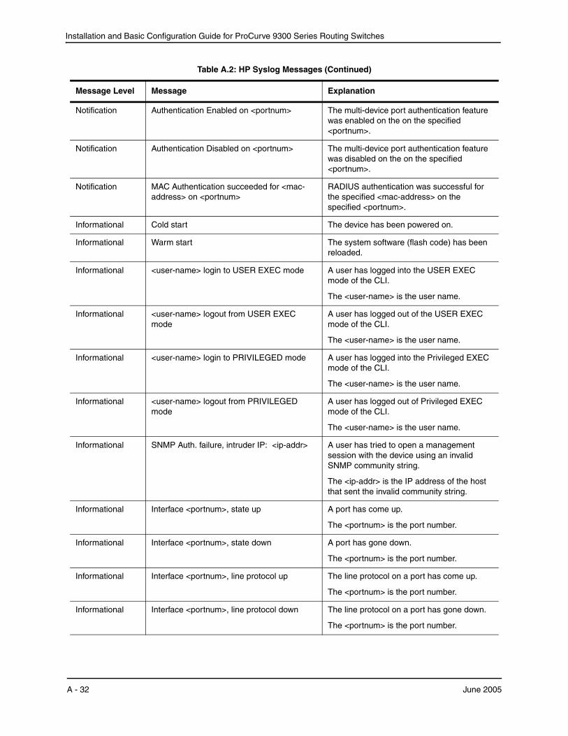
Installation and Basic Configuration Guide for ProCurve 9300 Series Routing Switches
Notification Authentication Enabled on <portnum> The multi-device port authentication feature was enabled on the on the specified <portnum>.
Notification Authentication Disabled on <portnum> The multi-device port authentication feature was disabled on the on the specified <portnum>.
Notification MAC Authentication succeeded for <mac-address> on <portnum>
RADIUS authentication was successful for the specified <mac-address> on the specified <portnum>.
Informational Cold start The device has been powered on.
Informational Warm start The system software (flash code) has been reloaded.
Informational <user-name> login to USER EXEC mode A user has logged into the USER EXEC mode of the CLI.
The <user-name> is the user name.
Informational <user-name> logout from USER EXEC mode
A user has logged out of the USER EXEC mode of the CLI.
The <user-name> is the user name.
Informational <user-name> login to PRIVILEGED mode A user has logged into the Privileged EXEC mode of the CLI.
The <user-name> is the user name.
Informational <user-name> logout from PRIVILEGED mode
A user has logged out of Privileged EXEC mode of the CLI.
The <user-name> is the user name.
Informational SNMP Auth. failure, intruder IP: <ip-addr> A user has tried to open a management session with the device using an invalid SNMP community string.
The <ip-addr> is the IP address of the host that sent the invalid community string.
Informational Interface <portnum>, state up A port has come up.
The <portnum> is the port number.
Informational Interface <portnum>, state down A port has gone down.
The <portnum> is the port number.
Informational Interface <portnum>, line protocol up The line protocol on a port has come up.
The <portnum> is the port number.
Informational Interface <portnum>, line protocol down The line protocol on a port has gone down.
The <portnum> is the port number.
Table A.2: HP Syslog Messages (Continued)
Message Level Message Explanation
A - 32 June 2005
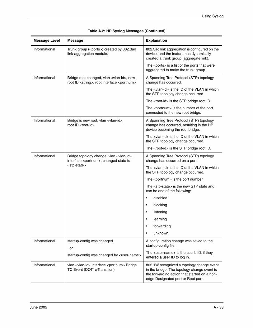
Using Syslog
Informational Trunk group (<ports>) created by 802.3ad link-aggregation module.
802.3ad link aggregation is configured on the device, and the feature has dynamically created a trunk group (aggregate link).
The <ports> is a list of the ports that were aggregated to make the trunk group.
Informational Bridge root changed, vlan <vlan-id>, new root ID <string>, root interface <portnum>
A Spanning Tree Protocol (STP) topology change has occurred.
The <vlan-id> is the ID of the VLAN in which the STP topology change occurred.
The <root-id> is the STP bridge root ID.
The <portnum> is the number of the port connected to the new root bridge.
Informational Bridge is new root, vlan <vlan-id>, root ID <root-id>
A Spanning Tree Protocol (STP) topology change has occurred, resulting in the HP device becoming the root bridge.
The <vlan-id> is the ID of the VLAN in which the STP topology change occurred.
The <root-id> is the STP bridge root ID.
Informational Bridge topology change, vlan <vlan-id>, interface <portnum>, changed state to <stp-state>
A Spanning Tree Protocol (STP) topology change has occurred on a port.
The <vlan-id> is the ID of the VLAN in which the STP topology change occurred.
The <portnum> is the port number.
The <stp-state> is the new STP state and can be one of the following:
• disabled
• blocking
• listening
• learning
• forwarding
• unknown
Informational startup-config was changed
or
startup-config was changed by <user-name>
A configuration change was saved to the startup-config file.
The <user-name> is the user’s ID, if they entered a user ID to log in.
Informational vlan <vlan-id> interface <portnum> Bridge TC Event (DOT1wTransition)
802.1W recognized a topology change event in the bridge. The topology change event is the forwarding action that started on a non-edge Designated port or Root port.
Table A.2: HP Syslog Messages (Continued)
Message Level Message Explanation
June 2005 A - 33
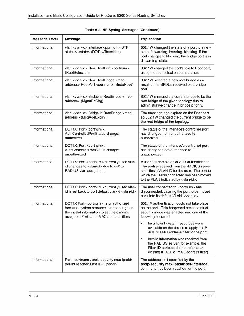
Installation and Basic Configuration Guide for ProCurve 9300 Series Routing Switches
Informational vlan <vlan-id> interface <portnum> STP state -> <state> (DOT1wTransition)
802.1W changed the state of a port to a new state: forwarding, learning, blocking. If the port changes to blocking, the bridge port is in discarding state.
Informational vlan <vlan-id> New RootPort <portnum> (RootSelection)
802.1W changed the port’s role to Root port, using the root selection computation.
Informational vlan <vlan-id> New RootBridge <mac-address> RootPort <portnum> (BpduRcvd)
802.1W selected a new root bridge as a result of the BPDUs received on a bridge port.
Informational vlan <vlan-id> Bridge is RootBridge <mac-address> (MgmtPriChg)
802.1W changed the current bridge to be the root bridge of the given topology due to administrative change in bridge priority.
Informational vlan <vlan-id> Bridge is RootBridge <mac-address> (MsgAgeExpiry)
The message age expired on the Root port so 802.1W changed the current bridge to be the root bridge of the topology.
Informational DOT1X: Port <portnum>, AuthControlledPortStatus change: authorized
The status of the interface’s controlled port has changed from unauthorized to authorized.
Informational DOT1X: Port <portnum>, AuthControlledPortStatus change: unauthorized
The status of the interface’s controlled port has changed from authorized to unauthorized.
Informational DOT1X: Port <portnum> currently used vlan-id changes to <vlan-id> due to dot1x-RADIUS vlan assignment
A user has completed 802.1X authentication. The profile received from the RADIUS server specifies a VLAN ID for the user. The port to which the user is connected has been moved to the VLAN indicated by <vlan-id>.
Informational DOT1X: Port <portnum> currently used vlan-id is set back to port default vlan-id <vlan-id>
The user connected to <portnum> has disconnected, causing the port to be moved back into its default VLAN, <vlan-id>.
Informational DOT1X Port <portnum> is unauthorized because system resource is not enough or the invalid information to set the dynamic assigned IP ACLs or MAC address filters
802.1X authentication could not take place on the port. This happened because strict security mode was enabled and one of the following occurred:
• Insufficient system resources were available on the device to apply an IP ACL or MAC address filter to the port
• Invalid information was received from the RADIUS server (for example, the Filter-ID attribute did not refer to an existing IP ACL or MAC address filter)
Informational Port <portnum>, srcip-security max-ipaddr-per-int reached.Last IP=<ipaddr>
The address limit specified by the srcip-security max-ipaddr-per-interface command has been reached for the port.
Table A.2: HP Syslog Messages (Continued)
Message Level Message Explanation
A - 34 June 2005
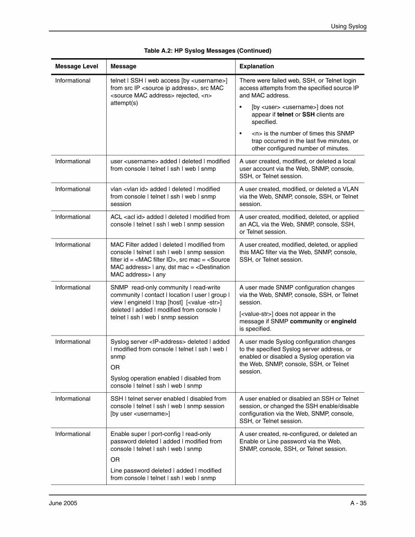
Using Syslog
Informational telnet | SSH | web access [by <username>] from src IP <source ip address>, src MAC <source MAC address> rejected, <n> attempt(s)
There were failed web, SSH, or Telnet login access attempts from the specified source IP and MAC address.
• [by <user> <username>] does not appear if telnet or SSH clients are specified.
• <n> is the number of times this SNMP trap occurred in the last five minutes, or other configured number of minutes.
Informational user <username> added | deleted | modified from console | telnet | ssh | web | snmp
A user created, modified, or deleted a local user account via the Web, SNMP, console, SSH, or Telnet session.
Informational vlan <vlan id> added | deleted | modified from console | telnet | ssh | web | snmp session
A user created, modified, or deleted a VLAN via the Web, SNMP, console, SSH, or Telnet session.
Informational ACL <acl id> added | deleted | modified from console | telnet | ssh | web | snmp session
A user created, modified, deleted, or applied an ACL via the Web, SNMP, console, SSH, or Telnet session.
Informational MAC Filter added | deleted | modified from console | telnet | ssh | web | snmp session filter id = <MAC filter ID>, src mac = <Source MAC address> | any, dst mac = <Destination MAC address> | any
A user created, modified, deleted, or applied this MAC filter via the Web, SNMP, console, SSH, or Telnet session.
Informational SNMP read-only community | read-write community | contact | location | user | group | view | engineld | trap [host] [<value -str>] deleted | added | modified from console | telnet | ssh | web | snmp session
A user made SNMP configuration changes via the Web, SNMP, console, SSH, or Telnet session.
[<value-str>] does not appear in the message if SNMP community or engineld is specified.
Informational Syslog server <IP-address> deleted | added | modified from console | telnet | ssh | web | snmp
OR
Syslog operation enabled | disabled from console | telnet | ssh | web | snmp
A user made Syslog configuration changes to the specified Syslog server address, or enabled or disabled a Syslog operation via the Web, SNMP, console, SSH, or Telnet session.
Informational SSH | telnet server enabled | disabled from console | telnet | ssh | web | snmp session [by user <username>]
A user enabled or disabled an SSH or Telnet session, or changed the SSH enable/disable configuration via the Web, SNMP, console, SSH, or Telnet session.
Informational Enable super | port-config | read-only password deleted | added | modified from console | telnet | ssh | web | snmp
OR
Line password deleted | added | modified from console | telnet | ssh | web | snmp
A user created, re-configured, or deleted an Enable or Line password via the Web, SNMP, console, SSH, or Telnet session.
Table A.2: HP Syslog Messages (Continued)
Message Level Message Explanation
June 2005 A - 35
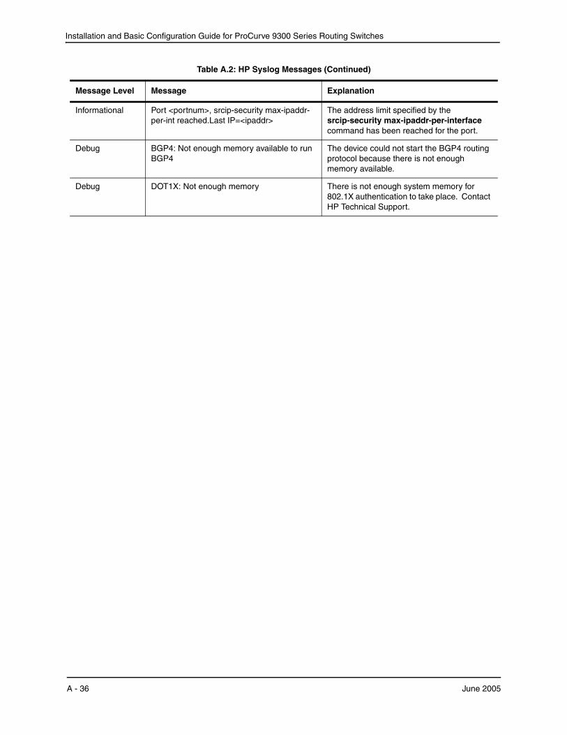
Installation and Basic Configuration Guide for ProCurve 9300 Series Routing Switches
Informational Port <portnum>, srcip-security max-ipaddr-per-int reached.Last IP=<ipaddr>
The address limit specified by the srcip-security max-ipaddr-per-interface command has been reached for the port.
Debug BGP4: Not enough memory available to run BGP4
The device could not start the BGP4 routing protocol because there is not enough memory available.
Debug DOT1X: Not enough memory There is not enough system memory for 802.1X authentication to take place. Contact HP Technical Support.
Table A.2: HP Syslog Messages (Continued)
Message Level Message Explanation
A - 36 June 2005

Appendix BEnhanced Performance (EP) Chassis Modules
NOTE: This appendix describes EP chassis modules. For general hardware information, including power specifications, see the “Hardware Specifications” in the Quick Start Guide shipped with your Routing Switch and also available on:
• The Documentation CD-ROM shipped with your HP ProCurve 9300 management modules
• The HP ProCurve website
For more information on HP ProCurve 9300 publications and how to get the latest versions from the HP ProCurve website, refer to “Organization of Product Documentation on page xv in this manual.
HP EP modules provide enhanced system performance through custom-designed ASICs.
Determining Your Device TypeRouting Switches are either EP or Standard (non-EP) devices, depending on whether the management module is an EP or Standard (non-EP) module. To determine whether a management module is EP or Standard,compare the part number (such as “J4885A”) to the part numbers in Table B.1.
EP ModulesTable B.1 lists the EP modules for 9300 series Routing Switches.
NOTE: You cannot use EP modules and non-EP modules in the same chassis.
Table B.1: 9300 series EP Modules
Model Description Ports Interface Type
J4885A Management module 8 mini-GBIC slots Gigabit-SX-LC Gigabit-LX-LC Gigabit-LH-LC 1000Base-T
J4881A/Ba Forwarding module 48 10/100 Ethernet ports RJ-45s for Cat-5 copper
June 2005 B - 1

Installation and Basic Configuration Guide for ProCurve 9300 Series Routing Switches
The modules listed in Table B.1 are described in the following sections.
The EP Management Module
Hardware OverviewEP ASICs
EP module ports are managed by the following custom ASICs:
• Integrated Gigabit Controllers (IGCs) – Ethernet packet controllers for Gigabit ports. Each Gigabit Ethernet module contains two IGCs.
• Integrated Packet Controllers (IPCs) – Ethernet packet controllers for 10/100 ports. Each 10/100 Ethernet module contains two IPCs.
These custom ASICs perform address lookup, data formatting and data movement for Ethernet packets. The Gigabit Ethernet modules use IGCs. The 10/100 modules use IPCs.
Each Gigabit Ethernet management or forwarding module has two IGCs.
• IGC 1 manages ports 1 – 4 on the module.
• IGC 2 manages ports 5 – 8 on the module.
Each 10/100 forwarding module has two IPCs:
• IPC 1 manages ports 1 – 24 on the module.
• IPC 2 manages ports 25 – 48 on the module.
Generally, you do not need to know which IGC or IPC is managing a port. However, the information is useful for a few features such as port monitoring. The documentation repeats the IGC and IPC port mapping information where needed.
Serial Management Interface
On management modules, the serial management interface enables you to configure and manage the device using a third-party terminal emulation application on a directly connected PC. A straight-through EIA/TIA DB-9 serial cable (M/F) is shipped with the device.
Reset Button
On management modules, the reset button allows you to restart the system. The button is recessed to prevent it from being pushed accidentally.
J4889A/B Forwarding module 48 10/100 Ethernet ports 50-pin Telco connectors for Cat-5 copper (12 ports per connector)
J4895A Forwarding module 16 Gigabit Ethernet Copper ports
RJ-45s for Cat-5 copper (100/1000 Mbps)
J4894A Forwarding module 16 mini-GBIC slots Gigabit-SX-LC Gigabit-LX-LC Gigabit-LH-LC
J78178A Forwarding module 24-port 100-FX
a.The J4881A/B module is a double-wide module. It occupies two chassis slots.
Table B.1: 9300 series EP Modules (Continued)
Model Description Ports Interface Type
B - 2 June 2005
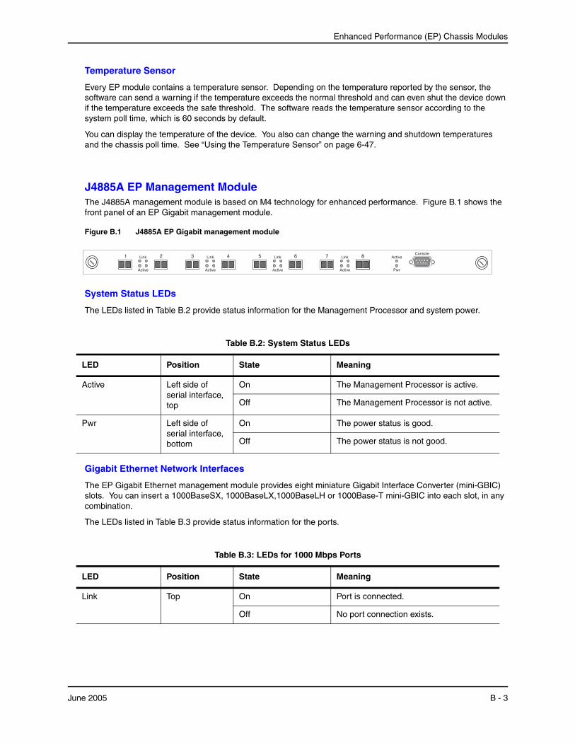
Enhanced Performance (EP) Chassis Modules
Temperature Sensor
Every EP module contains a temperature sensor. Depending on the temperature reported by the sensor, the software can send a warning if the temperature exceeds the normal threshold and can even shut the device down if the temperature exceeds the safe threshold. The software reads the temperature sensor according to the system poll time, which is 60 seconds by default.
You can display the temperature of the device. You also can change the warning and shutdown temperatures and the chassis poll time. See “Using the Temperature Sensor” on page 6-47.
J4885A EP Management ModuleThe J4885A management module is based on M4 technology for enhanced performance. Figure B.1 shows the front panel of an EP Gigabit management module.
Figure B.1 J4885A EP Gigabit management module
1 Link
Active
2 3 4Link
Active
5 Link
Active
6 7 8Link
Active Pwr
ActiveConsole
System Status LEDs
The LEDs listed in Table B.2 provide status information for the Management Processor and system power.
Table B.2: System Status LEDs
LED Position State Meaning
Active Left side of serial interface, top
On The Management Processor is active.
Off The Management Processor is not active.
Pwr Left side of serial interface, bottom
On The power status is good.
Off The power status is not good.
Gigabit Ethernet Network Interfaces
The EP Gigabit Ethernet management module provides eight miniature Gigabit Interface Converter (mini-GBIC) slots. You can insert a 1000BaseSX, 1000BaseLX,1000BaseLH or 1000Base-T mini-GBIC into each slot, in any combination.
The LEDs listed in Table B.3 provide status information for the ports.
Table B.3: LEDs for 1000 Mbps Ports
LED Position State Meaning
Link Top On Port is connected.
Off No port connection exists.
June 2005 B - 3

Installation and Basic Configuration Guide for ProCurve 9300 Series Routing Switches
EP Gigabit Ethernet Forwarding Module
J4895A 16-Port Forwarding ModuleFigure B.2 shows the front panel of an EP 16-port Gigabit forwarding module.
Figure B.2 J4895A EP Gigabit Copper forwarding module
01
LINK ACT
02 03 04 05 06 07 08 09 10 11 12 13 14 15 16
The J4895A module provides 16 RJ-45 connectors for Cat5 cabling. You can connect each port to a 100 Mbps or 1000 Mbps segment. The ports automatically detect the speed of the network and configure themselves accordingly. You also can manually configure a port for 100 Mbps or 1000 Mbps. The ports also support automatic MDI/MDIX crossover.
The pin assignments and the status LEDs are the same as the ones for the 100 and 1000 Mbps ports on other HP modules. See Table B.3 on page B-3.
EP 10/100 Ethernet Forwarding Modules
J4881A/B 48-Port Enterprise Forwarding ModuleFigure B.3 shows the front panel of an EP 10/100 RJ-45 forwarding module. This module occupies two chassis slots.
Figure B.3 J4881A/B EP 10/100 forwarding module
1
2
3
4
5
6
7
8
9
10
11
12
13
14
15
16
17
18
19
20
21
22
23
24
25
26
27
28
29
30
31
32
33
34
35
36
37
38
39
40
41
42
43
44
45
46
47
48
RJ-45 Interfaces
Each port on the J4881A/B module has its own RJ-45 connector. Each connector supports a 10/100 Ethernet network segment on Category 5 (Cat5) wire.
• Use a crossover cable to connect to another Routing Switch. A crossover cable swaps the wires so that the send signal on one port connects to the receive signal on the other port, and so on.
• Use a straight-through cable to connect to an end station or server. A straight-through cable does not swap the wires.
Figure B.4 shows the pin assignments and signalling for crossover connections on the 10/100 ports.
Activity Bottom On Traffic is being transmitted and received on that port.
Off No traffic is being transmitted.
Blinking Traffic is being transmitted and received on that port.
Table B.3: LEDs for 1000 Mbps Ports (Continued)
LED Position State Meaning
B - 4 June 2005
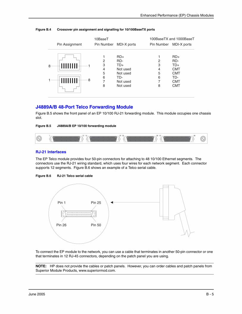
Enhanced Performance (EP) Chassis Modules
Figure B.4 Crossover pin assignment and signalling for 10/100BaseTX ports
Pin Assignment Pin Number
12345678
Pin Number
12345678
8 1
1 8
MDI-X ports
RD+RD-TD+Not used
TD-Not used
Not usedNot used
100BaseTX and 1000BaseT10BaseT
MDI-X ports
RD+RD-TD+CMT
TD-CMT
CMTCMT
J4889A/B 48-Port Telco Forwarding ModuleFigure B.5 shows the front panel of an EP 10/100 RJ-21 forwarding module. This module occupies one chassis slot.
Figure B.5 J4889A/B EP 10/100 forwarding module
12 131 24 25 36 37 48
RJ-21 Interfaces
The EP Telco module provides four 50-pin connectors for attaching to 48 10/100 Ethernet segments. The connectors use the RJ-21 wiring standard, which uses four wires for each network segment. Each connector supports 12 segments. Figure B.6 shows an example of a Telco serial cable.
Figure B.6 RJ-21 Telco serial cable
Pin 1 Pin 25
Pin 26 Pin 50
To connect the EP module to the network, you can use a cable that terminates in another 50-pin connector or one that terminates in 12 RJ-45 connectors, depending on the patch panel you are using.
NOTE: HP does not provide the cables or patch panels. However, you can order cables and patch panels from Superior Module Products, www.superiormod.com.
June 2005 B - 5

Installation and Basic Configuration Guide for ProCurve 9300 Series Routing Switches
Figure B.7 shows an example of a patch panel that accepts a 50-pin connector, and converts the signals to 12 RJ-45 sockets. Each of the RJ-45 sockets uses four signals per the RJ-21 wiring standard. You can use Cat5 cables with RJ-45 connectors to plug your network devices into the patch panel.
Figure B.7 Telco patch panel
1 2 3 4 5 6
7 8 9 10 11 12
37 38 39 40 41 42
43 44 45 46 47 48
13 14 15 16 17 18
19 20 21 22 23 24
25 26 27 28 29 30
31 32 33 34 35 36
Front - Plug thenetwork cableshere.
Rear - Plug thecable from the EPmodule here.
Table B.4 shows the output signals on each EP Telco 50-pin connector. Notice that each 10/100 port uses four signals. Two of the signals are for transmit and the other two are for receive. Signals 25 and 50 are not used.
Table B.4: Output Signals for RJ-21
10/100 Port Pin Number Signal Pin Number Signal
1 1 RxD ( - ) 26 RxD ( + )
2 TxD ( - ) 27 TxD ( + )
2 3 RxD ( - ) 28 RxD ( + )
4 TxD ( - ) 29 TxD ( + )
3 5 RxD ( - ) 30 RxD ( + )
6 TxD ( - ) 31 TxD ( + )
4 7 RxD ( - ) 32 RxD ( + )
8 TxD ( - ) 33 TxD ( + )
5 9 RxD ( - ) 34 RxD ( + )
10 TxD ( - ) 35 TxD ( + )
6 11 RxD ( - ) 36 RxD ( + )
12 TxD ( - ) 37 TxD ( + )
7 13 RxD ( - ) 38 RxD ( + )
14 TxD ( - ) 39 TxD ( + )
8 15 RxD ( - ) 40 RxD ( + )
16 TxD ( - ) 41 TxD ( + )
9 17 RxD ( - ) 42 RxD ( + )
18 TxD ( - ) 43 TxD ( + )
B - 6 June 2005
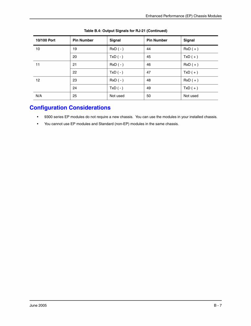
Enhanced Performance (EP) Chassis Modules
Configuration Considerations• 9300 series EP modules do not require a new chassis. You can use the modules in your installed chassis.
• You cannot use EP modules and Standard (non-EP) modules in the same chassis.
10 19 RxD ( - ) 44 RxD ( + )
20 TxD ( - ) 45 TxD ( + )
11 21 RxD ( - ) 46 RxD ( + )
22 TxD ( - ) 47 TxD ( + )
12 23 RxD ( - ) 48 RxD ( + )
24 TxD ( - ) 49 TxD ( + )
N/A 25 Not used 50 Not used
Table B.4: Output Signals for RJ-21 (Continued)
10/100 Port Pin Number Signal Pin Number Signal
June 2005 B - 7

Installation and Basic Configuration Guide for ProCurve 9300 Series Routing Switches
B - 8 June 2005

Appendix CSoftware Specifications
This appendix lists the following information:
• IEEE compliance
• RFC support
• ISO/IEC specification support
• Internet draft support
NOTE: For a list of features supported on a specific product, see the data sheet for that product.
IEEE ComplianceHP devices support the following standards.
• 802.1D Bridging
• 802.1p/q VLAN Tagging
• 802.1w Rapid Spanning Tree (RSTP)
• 802.1X Port-Based Network Access Control
• 802.3, 10BaseT
• 802.3ad Link Aggregation
• 802.3ae 10000BaseX
• 802.3u, 100BaseTX, 100BaseFX
• 802.3z 1000BaseSX, 1000BaseLX
• 802.3x Flow Control
June 2005 C - 1
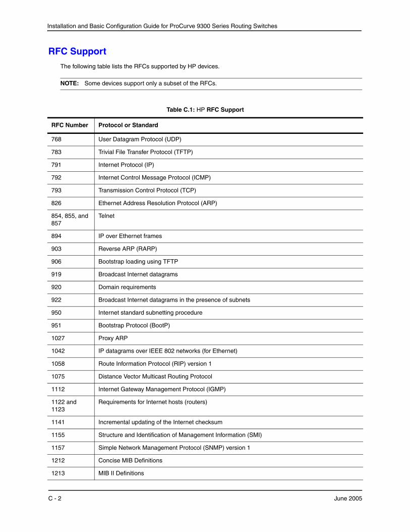
Installation and Basic Configuration Guide for ProCurve 9300 Series Routing Switches
RFC SupportThe following table lists the RFCs supported by HP devices.
NOTE: Some devices support only a subset of the RFCs.
Table C.1: HP RFC Support
RFC Number Protocol or Standard
768 User Datagram Protocol (UDP)
783 Trivial File Transfer Protocol (TFTP)
791 Internet Protocol (IP)
792 Internet Control Message Protocol (ICMP)
793 Transmission Control Protocol (TCP)
826 Ethernet Address Resolution Protocol (ARP)
854, 855, and 857
Telnet
894 IP over Ethernet frames
903 Reverse ARP (RARP)
906 Bootstrap loading using TFTP
919 Broadcast Internet datagrams
920 Domain requirements
922 Broadcast Internet datagrams in the presence of subnets
950 Internet standard subnetting procedure
951 Bootstrap Protocol (BootP)
1027 Proxy ARP
1042 IP datagrams over IEEE 802 networks (for Ethernet)
1058 Route Information Protocol (RIP) version 1
1075 Distance Vector Multicast Routing Protocol
1112 Internet Gateway Management Protocol (IGMP)
1122 and 1123
Requirements for Internet hosts (routers)
1141 Incremental updating of the Internet checksum
1155 Structure and Identification of Management Information (SMI)
1157 Simple Network Management Protocol (SNMP) version 1
1212 Concise MIB Definitions
1213 MIB II Definitions
C - 2 June 2005
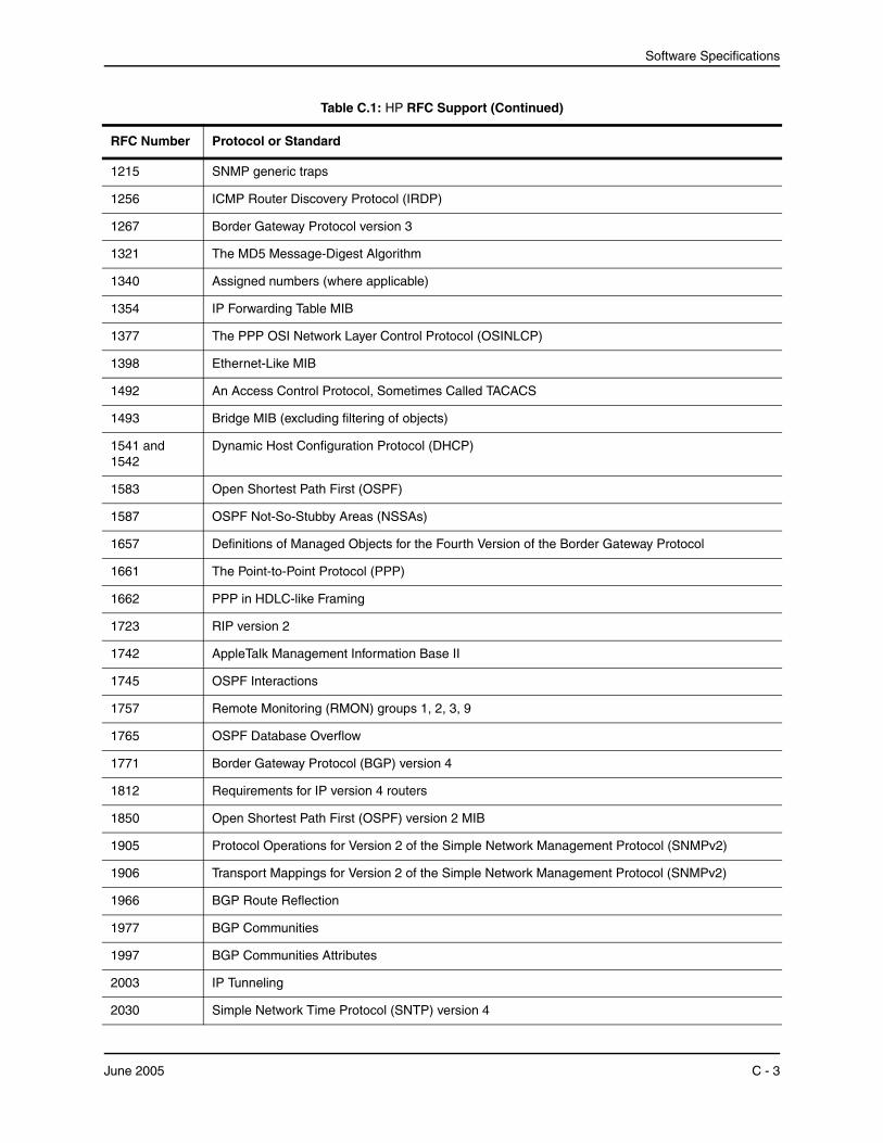
Software Specifications
1215 SNMP generic traps
1256 ICMP Router Discovery Protocol (IRDP)
1267 Border Gateway Protocol version 3
1321 The MD5 Message-Digest Algorithm
1340 Assigned numbers (where applicable)
1354 IP Forwarding Table MIB
1377 The PPP OSI Network Layer Control Protocol (OSINLCP)
1398 Ethernet-Like MIB
1492 An Access Control Protocol, Sometimes Called TACACS
1493 Bridge MIB (excluding filtering of objects)
1541 and 1542
Dynamic Host Configuration Protocol (DHCP)
1583 Open Shortest Path First (OSPF)
1587 OSPF Not-So-Stubby Areas (NSSAs)
1657 Definitions of Managed Objects for the Fourth Version of the Border Gateway Protocol
1661 The Point-to-Point Protocol (PPP)
1662 PPP in HDLC-like Framing
1723 RIP version 2
1742 AppleTalk Management Information Base II
1745 OSPF Interactions
1757 Remote Monitoring (RMON) groups 1, 2, 3, 9
1765 OSPF Database Overflow
1771 Border Gateway Protocol (BGP) version 4
1812 Requirements for IP version 4 routers
1850 Open Shortest Path First (OSPF) version 2 MIB
1905 Protocol Operations for Version 2 of the Simple Network Management Protocol (SNMPv2)
1906 Transport Mappings for Version 2 of the Simple Network Management Protocol (SNMPv2)
1966 BGP Route Reflection
1977 BGP Communities
1997 BGP Communities Attributes
2003 IP Tunneling
2030 Simple Network Time Protocol (SNTP) version 4
Table C.1: HP RFC Support (Continued)
RFC Number Protocol or Standard
June 2005 C - 3

Installation and Basic Configuration Guide for ProCurve 9300 Series Routing Switches
Internet DraftsIn addition to the RFCs listed in “RFC Support” on page C-2, the Routing Switches support the following Internet drafts:
• ietf-idmr-dvmrp version 3.05, obsoletes RFC 1075
• draft-ietf-pim-dm-05 (V1)
2068 HTTP
2138 Remote Authentication Dial In User Server (RADIUS)
2139 RADIUS Accounting
2178 Open Shortest Path First (OSPF)
2328 OSPF Version 2
Note: AS External LSA reduction is supported.
2336 IGMP Version 2
2338 Virtual Router Redundancy Protocol (VRRP)
2362 IP Multicast PIM Sparse
2385 TCP MD5 Signature Option (for BGP4)
2439 BGP Route Flap Dampening
2453 BGP Route Information Protocol (RIP) version 2
2570 Introduction to Version 3 of the Internet-standard Network Management Framework
2571 An Architecture of Describing SNMP Management Frameworks
2572 Message Processing and Dispatching for the Simple Network Management Protocol (SNMP)
2574 User-based Security (USM) for version 3 of the Simple Network Management Protocol (SNMPv3)
2575 View-based Access Control Model (VACM) for the Simple Network Management Protocol (SNMP)
2665 Ethernet Like MIB (incorporates RFC 1398)
2674 Definitions of Managed Objects for Bridges with Traffic Classes, Multicast Filtering and Virtual LAN Extensions
2796 BGP Route Reflection
2842 BGP Capability Advertisement
2858 BGP Multi-protocol Extension
2869 RADIUS Extensions
2918 Route Refresh Capability for BGP-4
3065 BGP Confederations
3176 InMon Corporation's sFlow: A Method for Monitoring Traffic in Switched and Routed Networks
Table C.1: HP RFC Support (Continued)
RFC Number Protocol or Standard
C - 4 June 2005

Software Specifications
• draft-ietf-pim-v2-dm-03 (V2)
• The TACACS+ Protocol version 1.78
June 2005 C - 5

Installation and Basic Configuration Guide for ProCurve 9300 Series Routing Switches
C - 6 June 2005
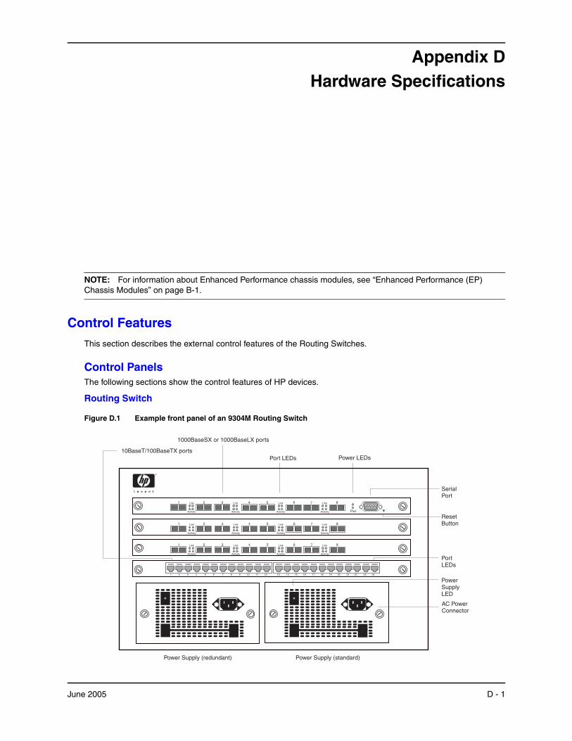
Appendix DHardware Specifications
NOTE: For information about Enhanced Performance chassis modules, see “Enhanced Performance (EP) Chassis Modules” on page B-1.
Control FeaturesThis section describes the external control features of the Routing Switches.
Control PanelsThe following sections show the control features of HP devices.
Routing Switch
Figure D.1 Example front panel of an 9304M Routing Switch
10BaseT/100BaseTX ports
3 542Link
Activity
61 7 8Link
Activity
Link
Activity
Link
Activity
1 2 3 4 5 6 7 8 9 10 11 12 13 14 15 16 17 18 19 20 21 22 23 24
3 542Link
Activity
61 7 8Link
Activity
Link
Activity
Link
Activity
Link
Activity
1 3 6 7 8542
Pwr
Link
Activity
Link
Activity
Link
Activity
1000BaseSX or 1000BaseLX ports
Port LEDs
SerialPort
Power LEDs
ResetButton
PortLEDs
AC PowerConnector
PowerSupplyLED
Power Supply (standard)Power Supply (redundant)
June 2005 D - 1

Installation and Basic Configuration Guide for ProCurve 9300 Series Routing Switches
PortsThe following port types are supported on ProCurve Routing Switches.
10 Gigabit Ethernet
The 10 Gigabit ports are compliant with the 10 Gigabit Ethernet standard, IEEE 802.3ae. HP 10 Gigabit ports support 1310nm and 1510nm serial connections to single-mode fiber. The port connectors are SC connectors.
1000BaseT Gigabit Copper (GC) Ports
The 1000BaseT Gigabit Copper (GC) ports are compliant with the IEEE 802.3ab standard and can provide Gigabit throughput over standard category-5 (“Cat-5”) copper wiring. The port connectors are RJ-45s, the same as the connectors on HP’s 10/100 modules. Thus, you can immediately deploy the GC ports without recabling.
Starting with Enterprise software release 07.7.00, copper mini-GBICs are supported on Gigabit Ethernet modules. You can use fiber mini-GBICs on some ports on a Gigabit Ethernet module, and copper mini-GBICs on others.
Copper mini-GBICs are supported only on EP Gigabit Ethernet modules. Note that the copper mini-GBICs can operate in 1000 Mbps autonegotiation mode only. You cannot configure them to operate in other modes.
10BaseT/100BaseTX Ports
The 10BaseT/100BaseTX ports are auto-sensing, auto-negotiating ports. Most have RJ-45 UTP connectors. These ports accept category-5 Unshielded Twisted Pair (UTP) cables. The EP 48-port Telco module uses RJ-21 connectors.
100BaseFX Ports
The 100BaseFX ports are equipped with MT-RJ connectors and operate at 100 Mbps in full-duplex mode.
1000BaseSX Ports
The 1000BaseSX ports operate in full-duplex mode and are equipped with SC connectors on fixed-configuration modules and can be mini-GBICs with LC connectors for mini-GBIC modules that support this port type. Multi-mode fiber cabling is supported.
1000BaseLX
The 1000BaseLX ports operate in full-duplex mode and are equipped with SC connectors on fixed-configuration modules and come as mini-GBICs for mini-GBIC modules that support this port type. Both single-mode fiber (SMF) and multi-mode fiber (MMF) cabling is supported. The 1000BaseLX ports must be connected to another 1000BaseLX port. Connection to a 1000BaseSX port is not supported.
NOTE: 1000BaseSX and 1000BaseLX ports also support auto-negotiation when the auto-gig option is enabled on the system.
NOTE: 1000BaseSX and 1000BaseLX ports operate only at full-duplex.
Slot and Port Numbers
The port numbers on the modules in Routing Switches are labeled, but the slot numbers are not labeled.
• Slots on a 4-slot chassis are numbered 1 – 4, from top to bottom.
• Slots on an 8-slot chassis are numbered 1 – 8, from left to right.
• Slots on a 15-slot chassis are numbered 1 – 15, from left to right.
You can place a management module in any slot. The slot numbers are absolute and do not change based on the position of the management module.
To specify a port on a Routing Switch, enter the slot number, a forward slash ( / ), and the number associated with the port on the device’s front panel. For example, to assign a name to Ethernet port 8 on the module installed in Chassis slot 2, enter the following commands:
ProCurveRS(config)# interface e 2/8
D - 2 June 2005
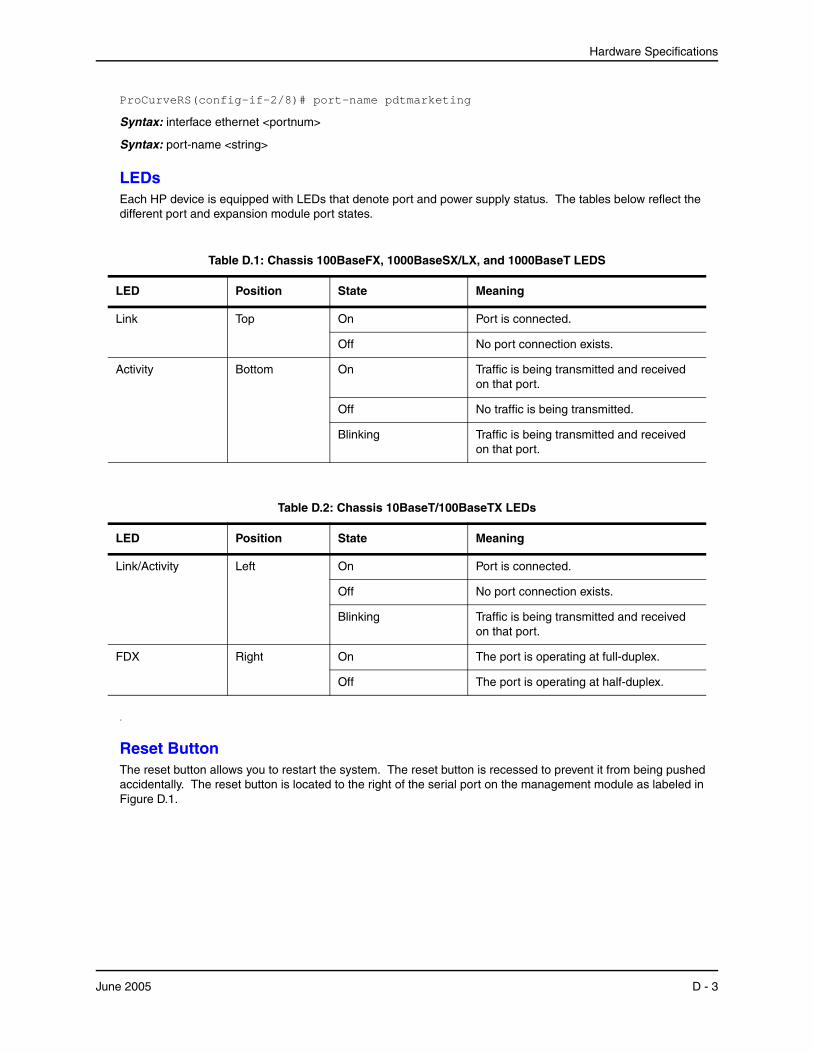
Hardware Specifications
ProCurveRS(config-if-2/8)# port-name pdtmarketing
Syntax: interface ethernet <portnum>
Syntax: port-name <string>
LEDsEach HP device is equipped with LEDs that denote port and power supply status. The tables below reflect the different port and expansion module port states.
Table D.1: Chassis 100BaseFX, 1000BaseSX/LX, and 1000BaseT LEDS
LED Position State Meaning
Link Top On Port is connected.
Off No port connection exists.
Activity Bottom On Traffic is being transmitted and received on that port.
Off No traffic is being transmitted.
Blinking Traffic is being transmitted and received on that port.
Table D.2: Chassis 10BaseT/100BaseTX LEDs
LED Position State Meaning
Link/Activity Left On Port is connected.
Off No port connection exists.
Blinking Traffic is being transmitted and received on that port.
FDX Right On The port is operating at full-duplex.
Off The port is operating at half-duplex.
.
Reset ButtonThe reset button allows you to restart the system. The reset button is recessed to prevent it from being pushed accidentally. The reset button is located to the right of the serial port on the management module as labeled in Figure D.1.
June 2005 D - 3
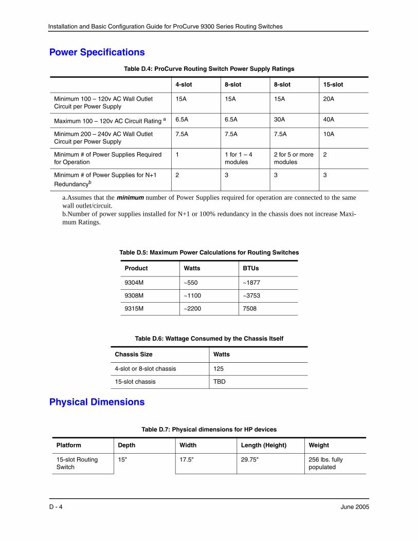
Installation and Basic Configuration Guide for ProCurve 9300 Series Routing Switches
Table D.4: ProCurve Routing Switch Power Supply Ratings
4-slot 8-slot 8-slot 15-slot
Minimum 100 – 120v AC Wall Outlet Circuit per Power Supply
15A 15A 15A 20A
Maximum 100 – 120v AC Circuit Rating
a.Assumes that the minimum number of Power Supplies required for operation are connected to the same wall outlet/circuit.
a 6.5A 6.5A 30A 40A
Minimum 200 – 240v AC Wall Outlet Circuit per Power Supply
7.5A 7.5A 7.5A 10A
Minimum # of Power Supplies Required for Operation
1 1 for 1 – 4 modules
2 for 5 or more modules
2
Minimum # of Power Supplies for N+1
Redundancy
b.Number of power supplies installed for N+1 or 100% redundancy in the chassis does not increase Maxi-mum Ratings.
b2 3 3 3
Power Specifications
Table D.5: Maximum Power Calculations for Routing Switches
Product Watts BTUs
9304M ~550 ~1877
9308M ~1100 ~3753
9315M ~2200 7508
Table D.6: Wattage Consumed by the Chassis Itself
Chassis Size Watts
4-slot or 8-slot chassis 125
15-slot chassis TBD
Physical Dimensions
Table D.7: Physical dimensions for HP devices
Platform Depth Width Length (Height) Weight
15-slot Routing Switch
15" 17.5" 29.75" 256 lbs. fully populated
D - 4 June 2005
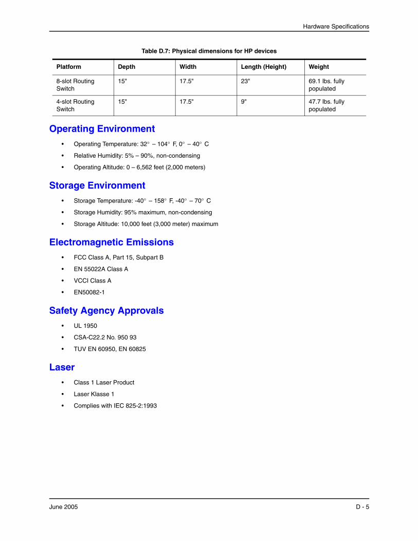
Hardware Specifications
Operating Environment• Operating Temperature: 32° – 104° F, 0° – 40° C
• Relative Humidity: 5% – 90%, non-condensing
• Operating Altitude: 0 – 6,562 feet (2,000 meters)
Storage Environment• Storage Temperature: -40° – 158° F, -40° – 70° C
• Storage Humidity: 95% maximum, non-condensing
• Storage Altitude: 10,000 feet (3,000 meter) maximum
Electromagnetic Emissions• FCC Class A, Part 15, Subpart B
• EN 55022A Class A
• VCCI Class A
• EN50082-1
Safety Agency Approvals• UL 1950
• CSA-C22.2 No. 950 93
• TUV EN 60950, EN 60825
Laser• Class 1 Laser Product
• Laser Klasse 1
• Complies with IEC 825-2:1993
8-slot Routing Switch
15" 17.5" 23" 69.1 lbs. fully populated
4-slot Routing Switch
15" 17.5" 9" 47.7 lbs. fully populated
Table D.7: Physical dimensions for HP devices
Platform Depth Width Length (Height) Weight
June 2005 D - 5

Installation and Basic Configuration Guide for ProCurve 9300 Series Routing Switches
D - 6 June 2005
Appendix ECautions and Warnings
The cautions and warnings that appear in this manual are listed below in English, German, French, and Spanish.
Cautions A caution calls your attention to a possible hazard that can damage equipment.
"Vorsicht" weist auf eine mögliche Beschädigung des Geräts hin. Sie finden die folgenden Vorsichtshinweise in diesem Handbuch.
Une mise en garde attire votre attention sur un risque possible d'endommagement de l'équipement. Ci-dessous, vous trouverez les mises en garde utilisées dans ce manuel.
Un mensaje de precaución le advierte sobre un posible peligro que pueda dañar el equipo. Las siguientes son precauciones utilizadas en este manual.
CAUTION: By default, the delete option deletes all files on the flash card. Make sure you specify the files you want to delete.
VORSICHT: Gemäß Vorgabe löscht die Option "Delete" (Löschen) alle Dateien auf der Flash-Karte. Stellen Sie sicher, dass Sie die zu löschenden Dateien angeben.
MISE EN GARDE: Par défaut, l'option de suppression supprime tous les fichiers de la carte mémoire. Assurez-vous de spécifier les fichiers que vous voulez supprimer.
PRECAUCIÓN: Por defecto, la opción de anular anula todos los archivos de la tarjeta flash. Verifique que especifica los archivos que quiere anular.
June 2005 E - 1
Installation and Basic Configuration Guide for ProCurve 9300 Series Routing Switches
CAUTION: Carefully follow the mechanical guides on each side of the power supply slot and make sure the power supply is properly inserted in the guides. Never insert the power supply upside down.
VORSICHT: Beachten Sie mechanischen Führungen an jeder Seite des Netzteils, das ordnungegemäß in die Führungen gesteckt werden muss. Das Netzteil darf niemals umgedreht eingesteckt werden.
MISE EN GARDE: Suivez attentivement les repères mécaniques de chaque côté du slot du bloc d'alimentation et assurez-vous que le bloc d'alimentation est bien inséré dans les repères. N'insérez jamais le bloc d'alimentation à l'envers.
PRECAUCIÓN: Siga cuidadosamente las guías mecánicas de cada lado de la ranura del suministro de energía y verifique que el suministro de energía está insertado correctamente en las guías. No inserte nunca el suministro de energía de manera invertida.
CAUTION: Do not add or remove a flash card while a file operation involving the flash card's slot is in progress. Doing so can result in corruption of the flash card. If this occurs, you may need to reformat the flash card to make it usable again. Reformatting the card erases all data stored on the card.
VORSICHT: Eine Flash-Karte darf nur dann eingesteckt oder herausgenommen werden, wenn keine Dateifunktion läuft, die der Flash-Karte bedarf. Wenn dies nicht beachtet wird, kann dies zur Korruption der Flash-Karte führen. Die Karte kann dann erst nach Neuformattierung wieder benutzt werden. Bei Neuformattietung gehen alle auf der Karte gespeicherten Daten verloren.
MISE EN GARDE: N'ajoutez pas ou ne supprimez pas une carte mémoire au cours d'une opération de fichier dans laquelle le slot de carte mémoire est impliqué. Vous risquez sinon de corrompre la carte mémoire. Si cela se produit, vous devrez peut-être reformater la carte mémoire pour qu'elle soit à nouveau utilisable. Le reformatage de la carte efface toutes les données qui y sont stockées.
PRECAUCIÓN: No añada ni quite una tarjeta flash mientras una operación de archivo que conlleve el uso de una ranura de tarjeta flash se encuentre en uso. De hacerlo así se podría dar lugar a la corrupción de la tarjeta flash. Si esto ocurriera, podría ser necesario que vuelva a formatear la tarjeta flash para hacer que vuelva sea utilizable. Cuando se formatea la tarjeta se borran todos los datos almacenados en la tarjeta.
CAUTION: Do not install the device in an environment where the operating ambient temperature might exceed 40° C (104° F).
VORSICHT: Das Gerät darf nicht in einer Umgebung mit einer Umgebungsbetriebstemperatur von über 40° C (104° F) installiert werden.
MISE EN GARDE: N'installez pas le dispositif dans un environnement où la température d'exploitation ambiante risque de dépasser 40° C (104° F).
PRECAUCIÓN: No instale el instrumento en un entorno en el que la temperatura ambiente de operación pueda exceder los 40°C (104° F).
CAUTION: Ensure that the device does not overload the power circuits, wiring, and over-current protection. To determine the possibility of overloading the supply circuits, add the ampere (amp) ratings of all devices installed on the same circuit as the device. Compare this total with the rating limit for the circuit. The maximum ampere ratings are usually printed on the devices near the input power connectors.
VORSICHT: Stromkreise, Verdrahtung und Überlastschutz dürfen nicht durch das Gerät überbelastet werden. Addieren Sie die Nennstromleistung (in Ampere) aller Geräte, die am selben Stromkreis wie das Gerät installiert sind. Somit können Sie feststellen, ob die Gefahr einer
E - 2 June 2005
Cautions and Warnings
Überbelastung der Versorgungsstromkreise vorliegt. Vergleichen Sie diese Summe mit der Nennstromgrenze des Stromkreises. Die Höchstnennströme (in Ampere) stehen normalerweise auf der Geräterückseite neben den Eingangsstromanschlüssen.
MISE EN GARDE: Assurez-vous que le dispositif ne risque pas de surcharger les circuits d'alimentation, le câblage et la protection de surintensité. Pour déterminer le risque de surcharge des circuits d'alimentation, additionnez l'intensité nominale (ampères) de tous les dispositifs installés sur le même circuit que le dispositif en question. Comparez alors ce total avec la limite de charge du circuit. L'intensité nominale maximum en ampères est généralement imprimée sur chaque dispositif près des connecteurs d'entrée d'alimentation.
PRECAUCIÓN: Verifique que el instrumento no sobrecargue los circuitos de corriente, el cableado y la protección para sobrecargas. Para determinar la posibilidad de sobrecarga en los circuitos de suministros, añada las capacidades nominales de corriente (amp) de todos los instrumentos instalados en el mismo circuito que el instrumento. Compare esta suma con el límite nominal para el circuito. Las capacidades nominales de corriente máximas están generalmente impresas en los instrumentos, cerca de los conectores de corriente de entrada.
CAUTION: Make sure the air flow around the front, sides, and back of the device is not restricted.
VORSICHT: Stellen Sie sicher, dass an der Vorderseite, den Seiten und an der Rückseite der Luftstrom nicht behindert wird.
MISE EN GARDE: Vérifiez que rien ne restreint la circulation d'air devant, derrière et sur les côtés du dispositif et qu'elle peut se faire librement.
PRECAUCIÓN: Asegúrese de que el flujo de aire en las inmediaciones de las partes anterior, laterales y posterior del instrumento no esté restringido.
CAUTION: Make sure the flash card is empty or does not contain files you want to keep. Formatting a flash card completely erases all files on the card.
VORSICHT: Stellen Sie sicher, dass die Flash-Karte leer ist oder keine Dateien auf ihr gespeichert sind, die Sie behalten möchten. Die Formattierung einer Flash-Karte löscht alle Dateien auf der Karte.
MISE EN GARDE: Vérifiez que la carte mémoire est vide ou ne contient pas de fichiers que vous voulez conserver. Le reformatage de la carte mémoire efface tous les fichiers qui s'y trouvent.
PRECAUCIÓN: Verifique que la tarjeta flash esté vacía o que no contenga archivos que desee conservar. Al formatear una tarjeta flash todos los archivos de ésta se borran.
CAUTION: Make sure you insert the power supply right-side up. It is possible to insert the supply upside down, although the supply will not engage with the power backplane when upside down. The power supply is right-side up when the power connector is on the left and the fan vent is on the right.
VORSICHT: Sicher Sie sicher, dass Sie das Netzteil mit der richtigen Seite nach oben weisend einstecken. Man kann die Karte auch umgekehrt einstecken. Allerdings rastet das umgekehrte Netzteil nicht in die Netzstrom-Rückwandplatine ein. Die rechte Seite des Netzteils weist nach oben, wenn sich der Stromanschlussstecker links und der Ventilatorschlitz rechts befindet.
MISE EN GARDE: Assurez-vous d'insérer le bloc d'alimentation dans le bon sens. Il est possible de l'insérer " la tête en bas ", mais le bloc d'alimentation ne s'enclenchera pas dans la face arrière
June 2005 E - 3
Installation and Basic Configuration Guide for ProCurve 9300 Series Routing Switches
d'alimentation s'il est inséré à l'envers. Le bloc d'alimentation est dans le bon sens lorsque le connecteur se trouve sur le côté gauche et le ventilateur sur la droite.
PRECAUCIÓN: Verifique que inserta el suministro de corriente con la cara correcta hacia arriba. Es posible insertar el suministro hacia abajo, pese a que este no se conectará con el enchufe posterior de esta forma. El suministro de potencia estará con la cara correcta hacia arriba cuando el conector de corriente quede a la izquierda y la abertura del ventilador queda a la derecha.
CAUTION: Never leave tools inside the chassis.
VORSICHT: Lassen Sie keine Werkzeuge im Chassis zurück.
MISE EN GARDE: Ne laissez jamais d'outils à l'intérieur du châssis.
PRECAUCIÓN: No deje nunca herramientas en el interior del chasis.
CAUTION: Once you start the formatting process, you cannot stop it. Even if you enter CTRL-C to stop the CLI output and a new prompt appears, the formatting continues. Make sure you want to format the card before you enter the command.
VORSICHT: Wenn Sie mit dem Formattieren beginnen, können Sie diesen Prozess nicht anhalten. Selbst wenn zum Anhalten der CLI-Ausgabe Strg-C drücken und eine neue Aufforderung gezeigt wird, wird mit dem Formattieren fortgefahren. Stellen Sie sicher, dass Sie die Karte formattieren wollen, bevor Sie den Befehl eingeben.
MISE EN GARDE: Une fois le processus de formatage commencé, vous ne pouvez pas l'interrompre. Même si vous appuyez sur CTRL-C pour arrêter la sortie CLI et si une nouvelle invite apparaît, le formatage continue. Soyez bien sûr de vouloir formater la carte avant d'entrer la commande.
PRECAUCIÓN: Una vez que empiece con el proceso de formateado, no se puede detener. Incluso si pulsa CTRL-C para detener la salida de CLI y aparece un nuevo indicador, el formateado continuará. Esté seguro que desea formatear la tarjeta antes de introducir el comando.
CAUTION: Remove the power cord from a power supply before you install it in or remove it from the device. Otherwise, the power supply or the device could be damaged as a result. (The device can be running while a power supply is being installed or removed, but the power supply itself should not be connected to a power source.)
VORSICHT: Nehmen Sie vor dem Anschließen oder Abtrennen des Geräts das Stromkabel vom Netzteil ab. Ansonsten könnten das Netzteil oder das Gerät beschädigt werden. (Das Gerät kann während des Anschließens oder Annehmens des Netzteils laufen. Nur das Netzteil sollte nicht an eine Stromquelle angeschlossen sein.)
MISE EN GARDE: Enlevez le cordon d'alimentation d'un bloc d'alimentation avant de l'installer ou de l'enlever du dispositif. Sinon, le bloc d'alimentation ou le dispositif risque d'être endommagé. (Le dispositif peut être en train de fonctionner lorsque vous installez ou enlevez un bloc d'alimentation, mais le bloc d'alimentation lui-même ne doit pas être connecté à une source d'alimentation.)
PRECAUCIÓN: Retire el cordón de corriente del suministro de corriente antes de instalarlo o retírarlo del instrumento. De no hacerse así, el suministro de corriente o el instrumento podrían resultar dañados. (El instrumento puede estar encendido mientras se instala o retira un suministro de corriente, pero el suministro de corriente en sí no deberá conectado a la corriente).
E - 4 June 2005
Cautions and Warnings
CAUTION: The software does not have an undelete option. Make sure you really want to delete the file.
VORSICHT: Die Software verfügt über keine Option "Undelete" (Löschung rückgängig machen). Stellen Sie sicher, dass Sie die Datei wirklich löschen wollen.
MISE EN GARDE: Le logiciel n'a pas d'option permettant d'annuler la suppression. Soyez donc bien sûr de vouloir supprimer le fichier.
PRECAUCIÓN: El software no dispone de una opción de recuperar lo anulado. Esté plenamente seguro de que quiere anular el archivo.
CAUTION: To provide additional safety and proper airflow to the device, make sure that slot cover plates are installed on all chassis slots that do not have either a module or power supply installed.
VORSICHT: Für mehr Sicherheit und eine bessere Luftzufuhr zum Gerät müssen Sie sicherstellen, dass die Abdeckplatten für die Steckplätze an allen Chassissteckplätzen montiert sind und dass in diesen keine Module oder Netzteile installiert sind.
MISE EN GARDE: Pour fournir une sécurité supplémentaire et une circulation d'air adéquate pour le dispositif, vérifiez que des caches de slots sont installés sur tous les slots du châssis dans lesquels un module ou un bloc d'alimentation n'est pas installé.
PRECAUCIÓN: Para proporcionar seguridad adicional y un flujo de aire apropiado al instrumento, verifique que las placas de cierre de las ranuras estén instaladas en todas las ranuras del chasis que no tengan un módulo o un suministro de corriente instalado.
CAUTION: Use at least two separate branch circuits for the power. This provides redundancy in case one of the circuits fails.
VORSICHT: Verwenden Sie wenigstens zwei getrennte Stromkreise für die Stromversorgung. Somit steht Ihnen im Fall des Ausfalls eines Stromkreises ein Ersatzstromkreis zur Verfügung.
MISE EN GARDE: Utilisez au moins deux circuits de dérivation différents pour l'alimentation. Ainsi, il y aura un circuit redondant en cas de panne d'un des circuits.
PRECAUCIÓN: Use al menos dos circuitos derivados separados para la corriente. Esto proporciona redundancia en el caso que uno de los circuitos falle.
CAUTION: Use the erase startup-config command only for new systems. If you enter this command on a system you have already configured, the command erases the configuration. If you accidentally do erase the configuration on a configured system, enter the write memory command to save the running configuration to the startup-config file.
VORSICHT: Verwenden Sie den Befehl "Erase startup-config" (Löschen Startup-Konfig) nur für neue Systeme. Wenn Sie diesen Befehl in ein bereits konfiguriertes System eingeben, löscht der Befehl die Konfiguration. Falls Sie aus Versehen die Konfiguration eines bereits konfigurierten Systems löschen, geben Sie den Befehl "Write Memory" (Speicher schreiben) ein, um die laufende Konfiguration in der Startup-Konfig-Datei zu speichern.
MISE EN GARDE: N'utilisez la commande erase startup-config que pour les nouveaux systèmes. Si vous entrez cette commande sur un système que vous avez déjà configuré, elle efface la configuration. Si vous effacez la configuration par accident sur un système configuré, entrez la commande write memory pour enregistrer la configuration actuelle dans le fichier startup-config.
PRECAUCIÓN: Use el comando erase startup-config (borrar configuración de inicio) para sistemas nuevos solamente. Si usted introduce este comando en un sistema que ya ha configurado, el comando borrará la configuración. Si usted borra accidentalmente la configuración en un sistema ya configurado, introduzca el comando write memory (escribir memoria) para guardar la configuración en ejecución en el archivo startup-config.
June 2005 E - 5
Installation and Basic Configuration Guide for ProCurve 9300 Series Routing Switches
CAUTION: When you connect a fan cable to a fan connector on the backplane, make sure the red wire in the connector is on the right side (for horizontally oriented connectors) or facing down (for vertically oriented connectors). If you accidentally reverse the wires, the fan will not operate. Also, make sure the fan cable connector is seated over all three pins on the backplane connector.
VORSICHT: Wenn Sie einen Ventilator an den Ventilatoranschlussstecker auf der Rückplatine anschließen, müssen Sie sicherstellen, dass sich der rote Draht im Anschlussstecker rechts befindet (bei waagerecht angeordneten Anschlusssteckern) oder nach unten weist (bei senkrecht angeordneten Anschlusssteckern). Wenn Sie die Drähte aus Versehen vertauschen, läuft der Ventilator nicht. Stellen Sie auch sicher, dass der Anschlussstecker des Ventilatorkabels auf allen drei Stiften am Rückplatinen-Anschlussstecker sitzt.
MISE EN GARDE: Lorsque vous connectez le câble d'un ventilateur à un connecteur de ventilateur sur la face arrière, vérifiez que le fil rouge dans le connecteur est bien sur le côté droit (pour les connecteurs orientés horizontalement) ou vers le bas (pour les connecteurs orientés verticalement). Si vous inversez les fils, le ventilateur ne fonctionnera pas. De plus, vérifiez que le connecteur du câble du ventilateur est bien en place sur les trois broches du connecteur de la face arrière.
PRECAUCIÓN: Cuando conecte un cable de ventilador a un conector de ventilador en el enchufe posterior, verifique que el cable rojo del conector está en el lado derecho (para conectores orientados horizontalmente) u orientado hacia abajo (para conectores orientados verticalmente). Si usted invierte los cables accidentalmente, el ventilador no funcionará. Asimismo, verifique que el conector del cable del ventilador queda asentado sobre las tres clavijas en el conector del enchufe posterior.
E - 6 June 2005
Cautions and Warnings
Warnings A warning calls your attention to a possible hazard that can cause injury or death. The following are the warnings used in this manual.
"Achtung" weist auf eine mögliche Gefährdung hin, die zu Verletzungen oder Tod führen können. Sie finden die folgenden Warnhinweise in diesem Handbuch:
Un avertissement attire votre attention sur un risque possible de blessure ou de décès. Ci-dessous, vous trouverez les avertissements utilisés dans ce manuel.
Una advertencia le llama la atención sobre cualquier posible peligro que pueda ocasionar daños personales o la muerte. A continuación se dan las advertencias utilizadas en este manual.
WARNING: The procedures in this manual are for qualified service personnel.
ACHTUNG: Die Verfahren in diesem Handbuch sind nur für qualifiziertes Wartungspersonal gedacht.
AVERTISSEMENT: Les procédures décrites dans ce manuel doivent être effectuées par le personnel de service qualifié uniquement.
ADVERTENCIA: Los procedimientos de este manual se han hecho para personal de servicio cualificado.
WARNING: All fiber-optic interfaces except LHB interfaces use Class 1 Lasers.
ACHTUNG: Alle Glasfaser-Schnittstellen verwenden Laser der Klasse 1.
AVERTISSEMENT: Toutes les interfaces en fibres optiques utilisent des lasers de classe 1.
ADVERTENCIA: Todas las interfaces de fibra óptica usan Láser de Clase 1.
WARNING: Before beginning the installation, see the precautions in "Power Precautions" on page 2-4.
ACHTUNG: Vor der Installation siehe Vorsichtsmaßnahmen unter " Power Precautions " (Vorsichtsmaßnahmen in Bezug auf elektrische Ablagen) auf den Seiten 2 - 4.
AVERTISSEMENT: Avant de commencer l'installation, consultez les précautions décrites dans " Power Precautions " (Précautions quant à l'alimentation), pages 2-4.
ADVERTENCIA: Antes de comenzar la instalación, consulte las precauciones en la sección " Power Precautions" (Precauciones sobre corriente) que se encuentra en las páginas 2-4.
WARNING: Disconnect the power cord from all power sources to completely remove power from the device.
ACHTUNG: Ziehen Sie das Stromkabel aus allen Stromquellen, um sicherzustellen, dass dem Gerät kein Strom zugeführt wird.
AVERTISSEMENT: Débranchez le cordon d'alimentation de toutes les sources d'alimentation pour couper complètement l'alimentation du dispositif.
ADVERTENCIA: Para desconectar completamente la corriente del instrumento, desconecte el cordón de corriente de todas las fuentes de corriente.
WARNING: Do not lift the 15-slot chassis using the lifting handles unless the chassis is empty. Remove the power supplies and interface modules before lifting the chassis.
ACHTUNG: Sie dürfen das 15-Steckplatz-Chassis nur dann an den Hebegriffen anheben, wenn das Chassis leer ist. Trennen Sie die Netzteile und Schnittstellenmodule vor dem Anheben des Chassis ab.
AVERTISSEMENT: Ne soulevez le châssis à 15 slots à l'aide des poignées de levage que si le châssis est vide. Enlevez les blocs d'alimentation et les modules d'interface avant de soulever le châssis.
June 2005 E - 7
Installation and Basic Configuration Guide for ProCurve 9300 Series Routing Switches
ADVERTENCIA: No alce el chasis de 15 ranuras usando las asas de alzado a menos que el chasis esté vacío. Retire los suministros de corriente y los módulos de interfaz antes de alzar el chasis.
WARNING: Do not use the handles on the power supply units to lift or carry a Routing Switch.
ACHTUNG: Die Griffe an den Netzteilen dürfen nicht zum Anheben oder Tragen eines Chassisgeräts verwendet werden.
AVERTISSEMENT: N'utilisez pas les poignées des unités de bloc d'alimentation pour soulever ou porter un dispositif en châssis.
ADVERTENCIA: No use las asas de las unidades de suministro de corriente para alzar o transportar un instrumento de chasis.
WARNING: If the installation requires a different power cord than the one supplied with the device, make sure you use a power cord displaying the mark of the safety agency that defines the regulations for power cords in your country. The mark is your assurance that the power cord can be used safely with the device.
ACHTUNG: Falls für die Installation ein anderes Stromkabel erforderlich ist (wenn das mit dem Gerät gelieferte Kabel nicht passt), müssen Sie sicherstellen, dass Sie ein Stromkabel mit dem Siegel einer Sicherheitsbehörde verwenden, die für die Zertifizierung von Stromkabeln in Ihrem Land zuständig ist. Das Siegel ist Ihre Garantie, dass das Stromkabel sicher mit Ihrem Gerät verwendet werden kann.
AVERTISSEMENT: Si l'installation nécessite un cordon d'alimentation autre que celui fourni avec le dispositif, assurez-vous d'utiliser un cordon d'alimentation portant la marque de l'organisation responsable de la sécurité qui définit les normes et régulations pour les cordons d'alimentation dans votre pays. Cette marque vous assure que vous pouvez utiliser le cordon d'alimentation avec le dispositif en toute sécurité.
ADVERTENCIA: Si la instalación requiere un cordón de corriente distinto al que se ha suministrado con el instrumento, verifique que usa un cordón de corriente que venga con la marca de la agencia de seguridad que defina las regulaciones para cordones de corriente en su país. Esta marca será su garantía de que el cordón de corriente puede ser utilizado con seguridad con el instrumento.
WARNING: Make sure that the power source circuits are properly grounded, then use the power cord supplied with the device to connect it to the power source.
ACHTUNG: Stellen Sie sicher, dass die Stromkreise ordnungsgemäß geerdet sind. Benutzen Sie dann das mit dem Gerät gelieferte Stromkabel, um es an die Srromquelle anzuschließen.
AVERTISSEMENT: Vérifiez que les circuits de sources d'alimentation sont bien mis à la terre, puis utilisez le cordon d'alimentation fourni avec le dispositif pour le connecter à la source d'alimentation.
ADVERTENCIA: Verifique que circuitos de la fuente de corriente están conectados a tierra correctamente; luego use el cordón de potencia suministrado con el instrumento para conectarlo a la fuente de corriente.
WARNING: Make sure the rack or cabinet housing the device is adequately secured to prevent it from becoming unstable or falling over.
ACHTUNG: Stellen Sie sicher, dass das Gestell oder der Schrank für die Unterbringung des Geräts auf angemessene Weise gesichert ist, so dass das Gestell oder der Schrank nicht wackeln oder umfallen kann.
AVERTISSEMENT: Vérifiez que le bâti ou le support abritant le dispositif est bien fixé afin qu'il ne devienne pas instable ou qu'il ne risque pas de tomber.
E - 8 June 2005

Cautions and Warnings
ADVERTENCIA: Verifique que el bastidor o armario que alberga el instrumento está asegurado correctamente para evitar que pueda hacerse inestable o que caiga.
WARNING: Mount the devices you install in a rack or cabinet as low as possible. Place the heaviest device at the bottom and progressively place lighter devices above.
ACHTUNG: Montieren Sie die Geräte im Gestell oder Schrank so tief wie möglich. Platzieren Sie das schwerste Gerät ganz unten, während leichtere Geräte je nach Gewicht (je schwerer desto tiefer) darüber untergebracht werden.
AVERTISSEMENT: Montez les dispositifs que vous installez dans un bâti ou support aussi bas que possible. Placez le dispositif le plus lourd en bas et le plus léger en haut, en plaçant tous les dispositifs progressivement de bas en haut du plus lourd au plus léger.
ADVERTENCIA: Monte los instrumentos que instale en un bastidor o armario lo más bajos posible. Ponga el instrumento más pesado en la parte inferior y los instrumentos progresivamente más livianos más arriba.
WARNING: Power supplies are hot swappable. However, Hewlett-Packard recommends that you disconnect the power supply from AC power before installing or removing the supply. The device can be running while a power supply is being installed or removed, but the power supply itself should not be connected to a power source. Otherwise, you could be injured or the power supply or other parts of the device could be damaged.
ACHTUNG: Netzteile können unter Strom stehend ausgetauscht werden. Allerdings empfiehlt Hewlett-Packard, dass Sie das Netzteil vom Netzstrom abtrennen, bevor Sie das Netzteil anschließen oder abtrennen. Das Gerät kann während des Anschließens oder Abnehmens des Netzteils laufen. Nur das Netzteil sollte nicht an eine Stromquelle angeschlossen sein. Ansonsten können Sie verletzt oder das Netzteil bzw. andere Geräteteile beschädigt werden.
AVERTISSEMENT: Les blocs d'alimentation peuvent être changés à chaud. Cependant, Hewlett-Packard vous conseille de débrancher le bloc d'alimentation de l'alimentation C.A. avant d'installer ou d'enlever le bloc d'alimentation. Le dispositif peut être en cours de fonctionnement pendant que vous installez ou enlevez un bloc d'alimentation, mais le bloc d'alimentation lui-même ne doit pas être connecté à une source d'alimentation. Sinon, vous risquez d'être blessé ou le bloc d'alimentation ou d'autres pièces du dispositif risquent d'être endommagés.
ADVERTENCIA: Los suministros de corriente pueden intercambiarse sin necesidad de ajustes. No obstante, Hewlett-Packard recomienda que desconecte el suministro de corriente de la toma de corriente alterna antes de instalar o retirar el suministro. El instrumento puede estar activado cuando se esté instalando o retirando un suministro de corriente, pero el suministro de corriente en sí no deberá estar conectado a la fuente de corriente. De no hacerlo así, podría sufrir daños personales o el suministro de corriente u otras piezas podrían resultar dañadas.
WARNING: The Routing Switches are very heavy, especially when fully populated with modules and power supplies. TWO OR MORE PEOPLE ARE REQUIRED WHEN LIFTING, HANDLING, OR MOUNTING THESE DEVICES.
ACHTUNG: Die Chassisgeräte sind sehr schwer. Dies gilt inbesondere, wenn sie mit vielen Modulen und Netzteilen bestückt sind. FÜR DAS ANHEBEN, TRANSPORTIEREN ODER MONTIEREN DIESER GERÄTE SIND WENIGSTENS ZWEI PERSONEN ERFORDERLICH.
AVERTISSEMENT: Les dispositifs en châssis sont très lourds, surtout s'ils sont entièrement remplis de modules et de blocs d'alimentation. POUR SOULEVER, MANIPULER OU MONTER CES DISPOSITIFS, DEUX PERSONNES MINIMUM SONT NÉCESSAIRES.
ADVERTENCIA: Los instrumentos del chasis son más pesados, especialmente cuando están muy cargados con módulos y suministros de corriente. SE REQUERIRÁN DOS O MÁS PERSONAS CUANDO ESTOS INSTRUMENTOS SE VAYAN A ALZAR, MANEJAR O MONTAR.
June 2005 E - 9
Installation and Basic Configuration Guide for ProCurve 9300 Series Routing Switches
WARNING: To avoid risk of shock, do not attach the clip end to the air flow panel of the power supply.
ACHTUNG: Das Klemmemende darf nicht an die Belüftungsplatte des Netzteils angeschlossen werden. Andernfalls setzen Sie sich dem Risiko eines elektrischen Schlags aus.
AVERTISSEMENT: Pour éviter le risque de choc électrique, n'attachez pas l'extrémité du clip au panneau de circulation d'air du bloc d'alimentation.
ADVERTENCIA: Para evitar riesgos de electrocución, no acople el extremo del clip al panel de flujo de aire del suministro de corriente.
WARNING: You can lift the 4-slot and 8-slot Routing Switches when they contain modules and power supplies. However, fully populated chassis are heavy. TWO OR MORE PEOPLE ARE REQUIRED WHEN LIFTING, HANDLING, OR MOUNTING THESE DEVICES.
ACHTUNG: Sie können ein 4-Steckplatz- und 8-Steckplatz-Chassis anheben, das mit Modulen und Netzteilen bestückt ist. Allerdings sind voll bestückte Chassis schwer. FÜR DAS ANHEBEN, TRANSPORTIEREN ODER MONTIEREN DIESER GERÄTE SIND WENIGSTENS ZWEI PERSONEN ERFORDERLICH.
AVERTISSEMENT: Vous pouvez soulever les dispositifs en châssis à 4 ou 8 slots lorsqu'ils contiennent des modules et des blocs d'alimentation. Cependant, les châssis sont lourds quand ils sont entièrement remplis. POUR SOULEVER, MANIPULER OU MONTER CES DISPOSITIFS, DEUX PERSONNES MINIMUM SONT NÉCESSAIRES.
ADVERTENCIA: Puede alzar los instrumentos de chasis de 4 y 8 ranuras cuando contengan módulos y suministros de corriente. Sin embargo, los chasis muy concurridos son pesados. SE REQUERIRÁN DOS O MÁS PERSONAS CUANDO ESTOS INSTRUMENTOS SE VAYAN A ALZAR, MANEJAR O MONTAR.
E - 10 June 2005
Index
Numerics10 Gigabit Ethernet 5-110/100
mode 6-241000BaseLx 2-7, D-21000BaseSx 2-7, D-21000BaseT D-2100BaseFx D-2802.1p
QoS priority 11-5802.1W 8-22
bridge parameters 8-50bridge port roles 8-23bridge port states 8-27compatibility with 802.1D 8-48convergence, link failure 8-42convergence, link restore 8-42convergence, start up 8-39edge port 8-25edge port states 8-27enable 8-49handshake, no root port 8-28handshake, with a root port 8-33port parameters 8-51show 8-52state machines 8-27topology change 8-45
802.3x Gigabit negotiation 6-269304M Routing Switch 2-11, 2-129308M Routing Switch 2-12
AAbout Blocked Ports 7-38Access
CLI 2-24lost password 2-16
Access levels 2-15Address
IP 2-17
AgeMAC 6-30
Age intervalIP multicast
Layer 2 12-1Agency approvals D-5Air Flow 2-18Air Flow, Caution 2-4Altitude D-5Ambient temperature 2-4Ampere Ratings 2-3AppleTalk
VLAN 11-3, 11-20AppleTalk cable VLAN 11-1, 11-28
configuring 11-62Assigning
IP address 2-17password 2-15
BBoot
software 15-10Broadcast
filter 6-40leaks 11-10limiting 6-17
BufferSyslog A-10, A-12
CCable
AppleTalk VLAN 11-28length 2-21Straight-through 2-13straight-through 2-23
June 2005 Index - 1

Installation and Basic Configuration Guide for ProCurve 9300 Series Routing Switches
Caution, Air Flow 2-4Caution, Circuit Overload 2-3Caution, grounding 2-3Caution, Power Cord 2-3Caution, Power Sockets 2-20Caution, Powering On 2-20Caution, Redundant Power Supply 2-2, 2-10Centerville 6-4Chassis
name 6-3poll interval 6-49replacing power supply 2-8slot and port numbers D-2swapping modules 2-4
CLIaccess 2-24access levels 2-15attaching serial cable 2-13command completion 2-25CONFIG Level 2-15line editing commands 2-25logging on 2-24Privileged EXEC Level 2-15scroll control 2-25securing access 2-16User EXEC level 2-15
Clock 6-13Command completion
CLI 2-25Community string
encryption 6-5CONFIG Level 2-15Configuration
displaying 15-11erasing 15-18saving 15-11
ConfiguringAppleTalk cable VLAN 11-28port-based VLAN 11-13, 11-17protocol VLAN
dynamic ports 11-31static ports 11-13
Configuring Security Features on a VSRP-Aware Device10-32Connection, Serial 2-1Connections 2-22Connector
console 2-13module 2-21
Consoleattaching 2-13
Console Attachment 2-13Console Settings 2-13Contact information 6-3Conventions
manual 1-1
Cooling 2-5Ctrl-A 2-25Ctrl-B 2-25Ctrl-C 2-26Ctrl-D 2-26Ctrl-E 2-26Ctrl-F 2-26Ctrl-K 2-26Ctrl-L 2-26Ctrl-N 2-26Ctrl-P 2-26Ctrl-R 2-26Ctrl-U 2-26Ctrl-W 2-26Ctrl-X 2-26Ctrl-Z 2-26
DDECnet
VLAN 11-3, 11-20Default
system 6-43Default VLAN 11-4, 11-13Desktop Installation 2-18Device location 6-3Dimensions D-4documentation, latest 2-xvDuplex mode 6-24Dynamic port 11-9, 11-31
aging 11-31
EElectromagnetic emissions D-5EMC Regulatory Statements 3-xxviEmissions D-5Enable password
assigning 2-16Enabling
STP 6-27, 8-3Encryption
SNMP community string 6-5Enhanced Performance 6-51Enhanced Performance (EP) B-1Event
Syslog A-3Excluded port
VLAN 11-10
FFacility
Syslog A-11Fiber
cabling 2-23File synchronization
redundant management module 3-10Filter
broadcast 6-40MAC address 6-34
Index - 2 June 2005

lock 6-42multicast 6-40, 12-1
Flow controldisabling 6-25
GGigabit
negotiation 6-15, 6-26Global CONFIG Level 2-16Grounding 1-ii, 2-3
HHalf-duplex mode 6-24Handles, Warning 2-2, 2-3, 2-18Hardware
installation 2-1LEDs D-3port D-2reset button D-3
Host name 6-3Hot Swap 2-4
modules 2-6redundant power supply 2-9
How Changing a Port’s VLAN Membership Affects Trunk Groups 7-35Humidity D-5
IIEEE tagging 6-34IGMP
Layer 2 12-1query
disabling 12-3IGMP snooping 12-3Installation
desktop 2-18hardware 2-1location and clearance 2-4precautions 2-3rack
chassis 2-19summary of 2-2
Installing a System 2-2Interface
number D-2virtual 11-3, 11-12
VLAN 11-8, 11-21Internet drafts supported C-4Internet Explorer version required 2-32IP
VLAN 11-3, 11-20IP Address
assigning 2-1IP address
assigning 2-17IP sub-net VLAN
configuring 11-59
IP subnet VLAN 11-1IPX
VLAN 11-3, 11-20IPX network VLAN 11-1
configuring 11-61ISR
VLAN 11-3, 11-12
LLAN Connections 2-22Laser specifications D-5Lasers
IEC compliance 3-xxvilatest documentation 2-xvLayer 2
age time 6-30configuring basic parameters 6-27MAC address filter 6-34VLAN 11-1, 11-2
configuring 11-13, 11-57default 11-4, 11-13modifying 11-17
Layer 3VLAN 11-1, 11-3, 11-20
configuring 11-58, 11-59, 11-61, 11-62LED Behavior 2-13LEDs D-3
redundant management module 3-7Lifting, warning 2-2Line editing commands 2-25Load sharing
trunk group 7-8Lock
MAC address 6-42Logging on
CLI 2-24Web management interface 2-31
MMAC
address filter 6-34address lock 6-42static entries 6-31, 6-33
Management II 3-1Management III 3-1Management module
redundant 3-1Manual nomenclature 1-1Mask, Network 2-1Message
TFTP error 15-20Mirror
port 6-50Mirror Ports for Policy-Based Routing (PBR) Traffic 6-54Mode
port 6-24Module
connectors 2-21
June 2005 Index - 3

Installation and Basic Configuration Guide for ProCurve 9300 Series Routing Switches
installing 2-4management
redundant 3-1redundant management 3-1
configuring 3-3default active module 3-5file synchronization 3-10status 3-7
removing 2-4Monitor
port 6-50Mounting
air flow 2-18warning 2-18
Multicastfilter 6-40, 12-1Layer 2 12-1
age interval 12-1query interval 12-1
limiting 6-17
NName
port 6-22Negotiation
Gigabit 6-15NetBIOS
VLAN 11-3, 11-20Netscape version required 2-32Network
connection 2-21network connections
troubleshooting 2-23Network Mask 2-1
OOperating environment D-5Operating temperature 2-4Other
VLAN 11-3, 11-20
PPackage contents 2-1Password 2-15
assigning 2-16lost
accessing the device 2-16Password, Lost 2-16PC
attaching 2-13Physical dimensions D-4Pin assignments
serial port 2-13Pinouts
serial port 2-15Poll interval 6-49Port
configuring basic parameters 6-20
disabling 6-24flow control 6-25hardware D-2IEEE tagging 6-34Layer 2 VLAN 11-1, 11-2logical 11-3, 11-12MAC address lock 6-42mirroring 6-50mode 6-24monitoring 6-50name 6-22number D-2port-based VLAN 6-33speed 6-23STP parameters 6-28, 8-4
VLAN 11-20tagged 11-5trunk group 7-1
displaying 7-22VLAN 11-11
virtual routing interfaceVLAN 11-8
VLANaging 11-31displaying information 11-64dynamic 11-9, 11-31excluded 11-10static 11-10types 11-8
Port-based VLANconfiguring 11-57default 11-4, 11-13
Power Cord 2-13caution 2-3, 2-20
Power supplyreplacing 2-8
Precautionsinstallation 2-3
Priority802.1p 11-5VLAN 11-18
Privileged EXEC Level 2-15, 2-16Prompt
customizing 2-14Protocol-based VLAN
configuring 11-58Proxy problem
Web management access 2-31publications, latest 2-xv
QQoS
priority802.1p 11-5VLAN 11-18
QueryIGMP
disabling 12-3
Index - 4 June 2005

Query intervalIP multicast
Layer 2 12-1
RRack installation
chassis 2-19Rack Mounting 2-3, 2-19
warning 2-3, 2-18Rack, Loading 2-3Redundant link
trunk group 7-1Redundant management module 3-1
configuring 3-3default active module 3-5file synchronization 3-10status 3-7
Redundant Power SupplyCaution 2-2installing 2-9removing 2-10
Regulatory Statements 3-xxvirelease notes 2-xviiReload
scheduled 15-18Reset button D-3RFCs supported C-2Route
VLAN 11-3, 11-11, 11-12, 11-21RPS
See Redundant Power Supply 2-2RSTP 8-22Running-config file 15-11
SScheduled reload 15-18Scroll control 2-25Security
assigning Enable password 2-16MAC address lock 6-42
Serial cable 2-13Serial Connection 2-1Serial Port Pinouts 2-15Service 1-iiSettings, Terminal 2-13Shock Hazard, Warning 2-20Single STP 8-62Slot Cover Plates, Air Flow 2-4Slot number D-2SNMP
community stringencryption 6-5
configuring 6-4Syslog A-3trap
disabling 6-8trap receiver 6-5trap source 6-6
SNTPserver 6-11
SoftwareRFC support C-2scheduled reload 15-18specifications C-1standards support C-1synchronization
redundant management module 3-10Specifications
software C-1Speed
port 6-23Standards supported C-1Startup-config file
erasing 15-18loading 15-11saving 15-11
State agency approvals D-5Static MAC entries 6-31, 6-33Static port 11-10Storage environment D-5STP
bridge and port parameters 6-28, 8-4bridge parameters
VLAN 11-19enabling or disabling 6-27, 8-3single 8-62VLAN 11-7, 11-18
Super User 2-16Suzy Creamcheese 6-4Swapping modules 2-4Switch
age time 6-30configuring basic Layer 2 parameters 6-27
Switchoverredundant management module 3-2Syslog messages 3-9
Syslog A-3buffer A-10, A-12changing facility A-11disabling message level A-10redundant management switchover 3-9server A-9temperature 6-48
Systemconfiguring basic parameters 6-3defaults 6-43installation 2-2name 6-3scheduled reload 15-18unpacking 2-1
TTagged port 11-5Temperature 2-4, D-5
displaying 6-47poll interval 6-49
June 2005 Index - 5
Installation and Basic Configuration Guide for ProCurve 9300 Series Routing Switches
sensor 3-1changing warning and shutdown levels 6-48
Syslog 6-48Terminal Settings 2-13TFTP
error message 15-20Time
SNTP server 6-11system clock 6-13
Trapdisabling 6-8receiver 6-5source 6-6Syslog A-3
Troubleshooting network connections 2-23Trunk group 7-1
displaying 7-22load sharing 7-8VLAN 11-11
UUnknown-unicast rate
limiting 6-17Unpacking a System 2-1User EXEC level 2-15UTP
cabling 2-23
VVirtual interface 11-3, 11-12, 11-21Virtual routing interface
VLAN 11-8VLAN
AppleTalk cable 11-1, 11-28broadcast leaks 11-10configuring 11-1default 11-4, 11-13displaying information 11-63displaying port information 11-64displaying summary information 11-63dynamic port 11-9, 11-31
aging 11-31excluded port 11-10IEEE tagging 6-34IP subnet 11-1IPX network 11-1ISR 11-3, 11-12Layer 2 port-based 11-1, 11-2Layer 3 protocol-based 11-1, 11-3, 11-20port-based 6-33, 11-13, 11-17QoS priority 11-18route 11-11same subnet on multiple VLANs 11-33static port 11-10STP 11-7, 11-18trunk group 11-11types 11-1virtual interface 11-3, 11-12, 11-21
virtual routing interface 11-8
WWarning
handles 2-2, 2-3, 2-18rack or cabinet secured 2-3system placement in rack 2-18weight 2-2, 2-3
Warning, Electrical Shock Hazard, Warning 2-20Warranty 1-iiWeb management interface
logging on 2-31password 2-31proxy problem 2-31user name 2-31using 2-31
Weightwarning 2-3, 2-18, 2-20
ZZappa 6-4
Index - 6 June 2005

Backcover

Technical information in this document is subject to change without notice.
© Copyright 2000, 2005 Hewlett-Packard Development Company, L.P. All rights reserved. Reproduction, adaptation, or translation without prior written permission is prohibited except as allowed under the copyright laws.
June 2005
Manual Part Number5990-6028