Embed Size (px)
Citation preview

Procurement Specification DA-300
V 4 2017-04-04
Procurement Specification for DA-300
Table of Contents
Contents
Introduction ............................................................................................................................................................ 1
1) Hardware ............................................................................................................................................... 1
2) Functionality ......................................................................................................................................... 4
3) Cabinet interfaces ............................................................................................................................... 6
4) LED Displays ......................................................................................................................................... 7
5) DA-300 Parameter Receipt and Data Posting (Communications) ................................... 7
6) DA-300 Internals ................................................................................................................................. 7
7) System Security ................................................................................................................................... 8
8) iCITE G2 Diagnostic Information .................................................................................................. 8
9) SQL Structured Query Language Data Extraction .................................................................. 8
10) Hardware Pin Assignments ............................................................................................................ 8
11) Standards Compliance .................................................................................................................... 12
Page 1 DA-300 Procurement Specification V4 2017-04-04
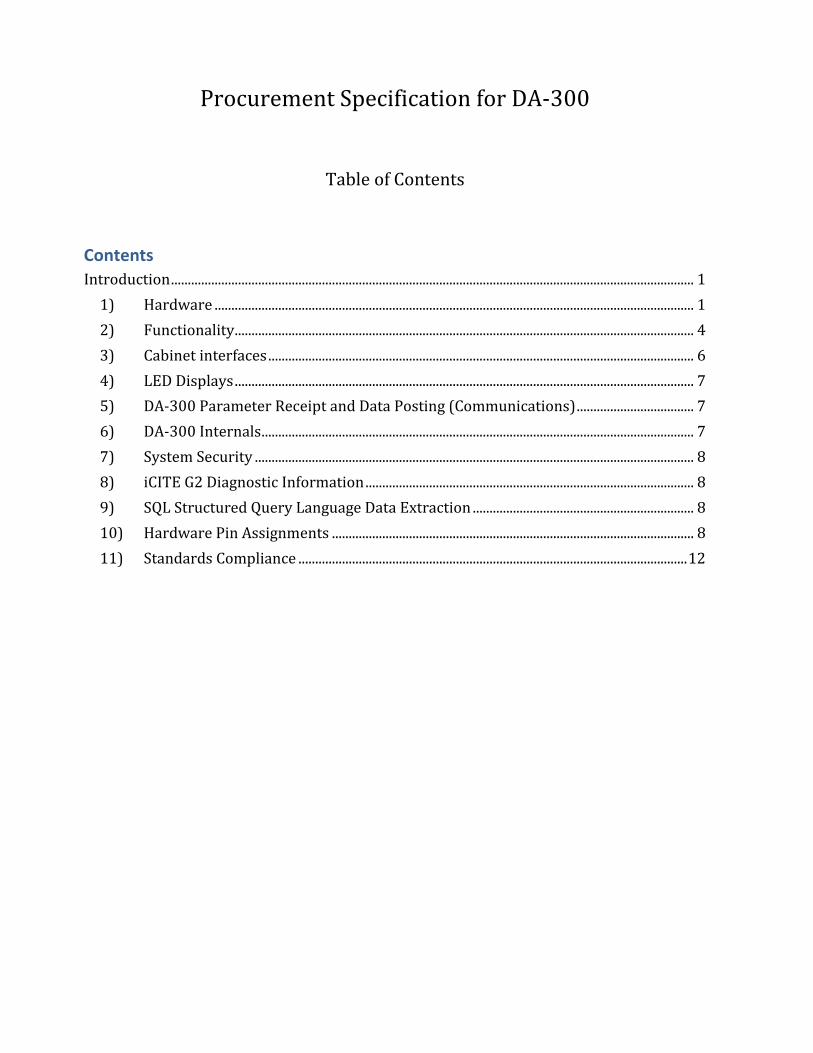
Procurement Specification for DA-300
Introduction This specification is for the DA-300. These devices shall be used to collect important information from the traffic signal cabinet or school flasher cabinet. The device shall be used for remote intersections as a means to communicate back to a traffic signal technician or traffic engineer the information provided in this document. In locations where a traffic cabinet or school flasher cabinet is connected to a Traffic Operations Center (TOC) and an Advanced Traffic Management System (ATMS), then the device shall be used to provide “last gasp” data or data not otherwise available to the TOC.
1) Hardware
1) The DA-300 shall measure 5.487” (D) X 8.18” (H) X 3.5” (W). (13.936 cm X 20.772 cm X 8.89
cm.)
2) The operating temperature of the DA-300 shall be - 40ºF to 176ºF (-40ºC to 80ºC) with humidity
ranging from 5% - 95% non-condensing.
3) The weight of the DA-300 including the battery shall not exceed 4.0 lbs. (1.81Kg)
4) The DA-300 shall have, on the rear side of the box, a DC or AC power supply connector.
a) The Power supply input shall be 24 VDC and have an operating range of between 18 VDC
and 30 VDC,
b) There shall be an optional AC power supply version.
i) This version shall use 120 AC voltage as the power source for the DA-300 instead of 24
VDC.
c) The DA-300 shall have a maximum operating power consumption of 2.0 Amps with the Cell
and GPS operational.
5) The DA-300 shall have, on the back side of the box, connectors for 5 harnesses herein named C1
– C5 with 3 pins, 10 pins, 10 pins, 20 pins, and 20 pins respectively.
a) C1 (DC POWER) shall be for the Analog DC input for powering the DA-300 device.
i) Optional AC POWER connector shall also be used in AC units.
b) C2 (ANALOG AC INPUTS) shall be for Analog AC inputs for measuring voltages from 0 – 130
VAC.
c) C3 (ANALOG DC INPUTS) shall be for Analog DC inputs which measures voltages from 0 –
30 VDC.
d) C4 (RELAY/PED) shall be Digital Outputs and Pedestrian Pushbutton inputs
i) There shall be three (3) relays for user programmed functions with both N.O. (normally
open) and N.C. (normally closed) contact closures.
ii) There shall be one relay output, with both N.O. and N.C. contact closures for providing a
Sync pulse or Line Sync used by controllers to set their internal clocks in the absence of
an NTP server.
iii) There shall be four (4) inputs for pedestrian push button monitoring.
Page 2 DA-300 Procurement Specification V4 2017-04-04
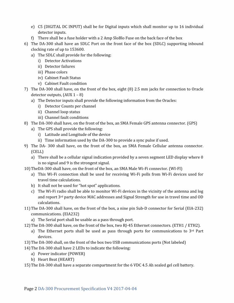
e) C5 (DIGITAL DC INPUT) shall be for Digital inputs which shall monitor up to 16 individual
detector inputs.
f) There shall be a fuse holder with a 2 Amp SloBlo Fuse on the back face of the box
6) The DA-300 shall have an SDLC Port on the front face of the box (SDLC) supporting inbound
clocking rate of up to 153600.
a) The SDLC shall provide for the following:
i) Detector Activations
ii) Detector failures
iii) Phase colors
iv) Cabinet Fault Status
v) Cabinet Fault condition
7) The DA-300 shall have, on the front of the box, eight (8) 2.5 mm jacks for connection to Oracle
detector outputs, (AUX 1 – 8)
a) The Detector inputs shall provide the following information from the Oracles:
i) Detector Counts per channel
ii) Channel loop status
iii) Channel fault conditions
8) The DA-300 shall have, on the front of the box, an SMA Female GPS antenna connector. (GPS)
a) The GPS shall provide the following:
i) Latitude and Longitude of the device
ii) Time information used by the DA-300 to provide a sync pulse if used.
9) The DA- 300 shall have, on the front of the box, an SMA Female Cellular antenna connector.
(CELL)
a) There shall be a cellular signal indication provided by a seven segment LED display where 0
is no signal and 9 is the strongest signal.
10) TheDA-300 shall have, on the front of the box, an SMA Male Wi-Fi connector. (WI-FI)
a) This Wi-Fi connection shall be used for receiving Wi-Fi polls from Wi-Fi devices used for
travel time calculations.
b) It shall not be used for “hot spot” applications.
c) The Wi-Fi radio shall be able to monitor Wi-Fi devices in the vicinity of the antenna and log
and report 3rd party device MAC addresses and Signal Strength for use in travel time and OD
calculations.
11) The DA-300 shall have, on the front of the box, a nine pin Sub-D connector for Serial (EIA-232)
communications. (EIA232)
a) The Serial port shall be usable as a pass through port.
12) The DA-300 shall have, on the front of the box, two RJ-45 Ethernet connectors. (ETH1 / ETH2).
a) The Ethernet ports shall be used as pass through ports for communications to 3rd Part
devices.
13) The DA-300 shall, on the front of the box two USB communications ports (Not labeled)
14) The DA-300 shall have 2 LEDs to indicate the following:
a) Power indicator (POWER)
b) Heart Beat (HEART)
15) The DA-300 shall have a separate compartment for the 6 VDC 4.5 Ah sealed gel cell battery.
Page 3 DA-300 Procurement Specification V4 2017-04-04
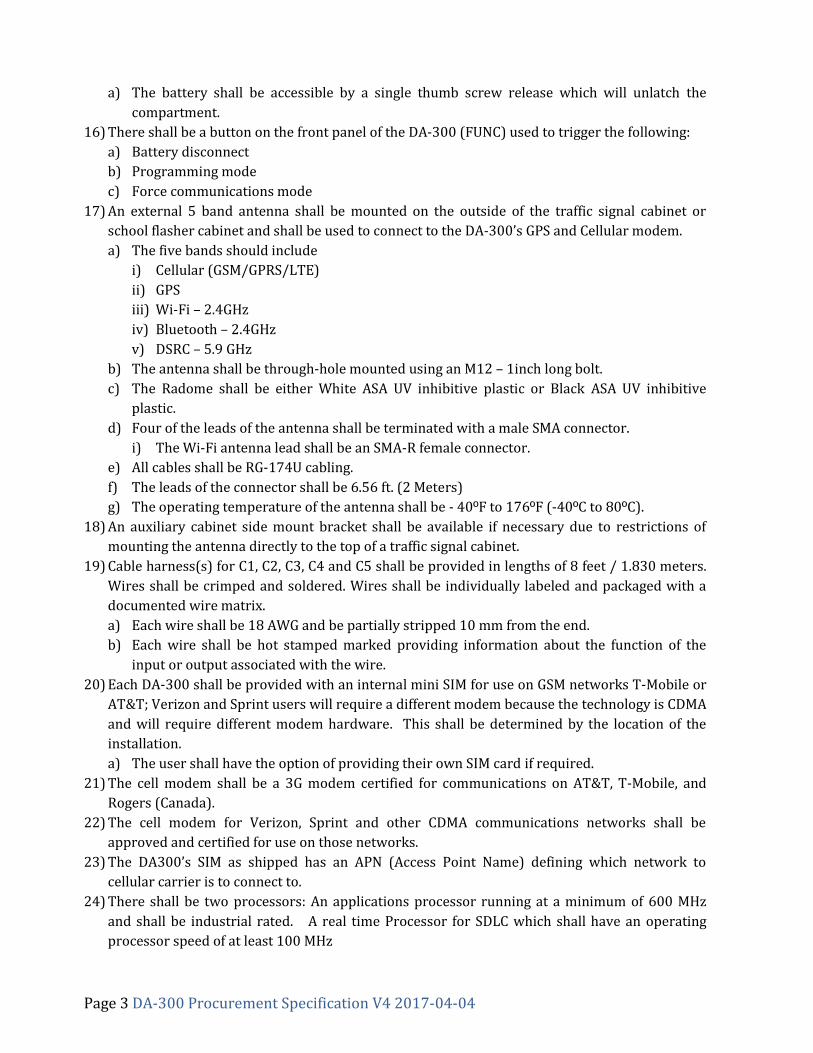
a) The battery shall be accessible by a single thumb screw release which will unlatch the
compartment.
16) There shall be a button on the front panel of the DA-300 (FUNC) used to trigger the following:
a) Battery disconnect
b) Programming mode
c) Force communications mode
17) An external 5 band antenna shall be mounted on the outside of the traffic signal cabinet or
school flasher cabinet and shall be used to connect to the DA-300’s GPS and Cellular modem.
a) The five bands should include
i) Cellular (GSM/GPRS/LTE)
ii) GPS
iii) Wi-Fi – 2.4GHz
iv) Bluetooth – 2.4GHz
v) DSRC – 5.9 GHz
b) The antenna shall be through-hole mounted using an M12 – 1inch long bolt.
c) The Radome shall be either White ASA UV inhibitive plastic or Black ASA UV inhibitive
plastic.
d) Four of the leads of the antenna shall be terminated with a male SMA connector.
i) The Wi-Fi antenna lead shall be an SMA-R female connector.
e) All cables shall be RG-174U cabling.
f) The leads of the connector shall be 6.56 ft. (2 Meters)
g) The operating temperature of the antenna shall be - 40ºF to 176ºF (-40ºC to 80ºC).
18) An auxiliary cabinet side mount bracket shall be available if necessary due to restrictions of
mounting the antenna directly to the top of a traffic signal cabinet.
19) Cable harness(s) for C1, C2, C3, C4 and C5 shall be provided in lengths of 8 feet / 1.830 meters.
Wires shall be crimped and soldered. Wires shall be individually labeled and packaged with a
documented wire matrix.
a) Each wire shall be 18 AWG and be partially stripped 10 mm from the end.
b) Each wire shall be hot stamped marked providing information about the function of the
input or output associated with the wire.
20) Each DA-300 shall be provided with an internal mini SIM for use on GSM networks T-Mobile or
AT&T; Verizon and Sprint users will require a different modem because the technology is CDMA
and will require different modem hardware. This shall be determined by the location of the
installation.
a) The user shall have the option of providing their own SIM card if required.
21) The cell modem shall be a 3G modem certified for communications on AT&T, T-Mobile, and
Rogers (Canada).
22) The cell modem for Verizon, Sprint and other CDMA communications networks shall be
approved and certified for use on those networks.
23) The DA300’s SIM as shipped has an APN (Access Point Name) defining which network to
cellular carrier is to connect to.
24) There shall be two processors: An applications processor running at a minimum of 600 MHz
and shall be industrial rated. A real time Processor for SDLC which shall have an operating
processor speed of at least 100 MHz
Page 4 DA-300 Procurement Specification V4 2017-04-04
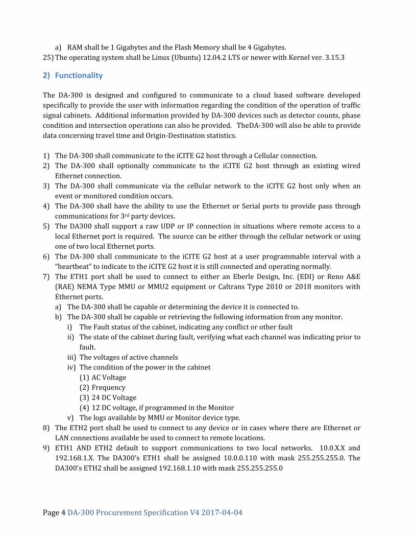
a) RAM shall be 1 Gigabytes and the Flash Memory shall be 4 Gigabytes.
25) The operating system shall be Linux (Ubuntu) 12.04.2 LTS or newer with Kernel ver. 3.15.3
2) Functionality
The DA-300 is designed and configured to communicate to a cloud based software developed
specifically to provide the user with information regarding the condition of the operation of traffic
signal cabinets. Additional information provided by DA-300 devices such as detector counts, phase
condition and intersection operations can also be provided. TheDA-300 will also be able to provide
data concerning travel time and Origin-Destination statistics.
1) The DA-300 shall communicate to the iCITE G2 host through a Cellular connection.
2) The DA-300 shall optionally communicate to the iCITE G2 host through an existing wired
Ethernet connection.
3) The DA-300 shall communicate via the cellular network to the iCITE G2 host only when an
event or monitored condition occurs.
4) The DA-300 shall have the ability to use the Ethernet or Serial ports to provide pass through
communications for 3rd party devices.
5) The DA300 shall support a raw UDP or IP connection in situations where remote access to a
local Ethernet port is required. The source can be either through the cellular network or using
one of two local Ethernet ports.
6) The DA-300 shall communicate to the iCITE G2 host at a user programmable interval with a
“heartbeat” to indicate to the iCITE G2 host it is still connected and operating normally.
7) The ETH1 port shall be used to connect to either an Eberle Design, Inc. (EDI) or Reno A&E
(RAE) NEMA Type MMU or MMU2 equipment or Caltrans Type 2010 or 2018 monitors with
Ethernet ports.
a) The DA-300 shall be capable or determining the device it is connected to.
b) The DA-300 shall be capable or retrieving the following information from any monitor.
i) The Fault status of the cabinet, indicating any conflict or other fault
ii) The state of the cabinet during fault, verifying what each channel was indicating prior to
fault.
iii) The voltages of active channels
iv) The condition of the power in the cabinet
(1) AC Voltage
(2) Frequency
(3) 24 DC Voltage
(4) 12 DC voltage, if programmed in the Monitor
v) The logs available by MMU or Monitor device type.
8) The ETH2 port shall be used to connect to any device or in cases where there are Ethernet or
LAN connections available be used to connect to remote locations.
9) ETH1 AND ETH2 default to support communications to two local networks. 10.0.X.X and
192.168.1.X. The DA300’s ETH1 shall be assigned 10.0.0.110 with mask 255.255.255.0. The
DA300’s ETH2 shall be assigned 192.168.1.10 with mask 255.255.255.0
Page 5 DA-300 Procurement Specification V4 2017-04-04
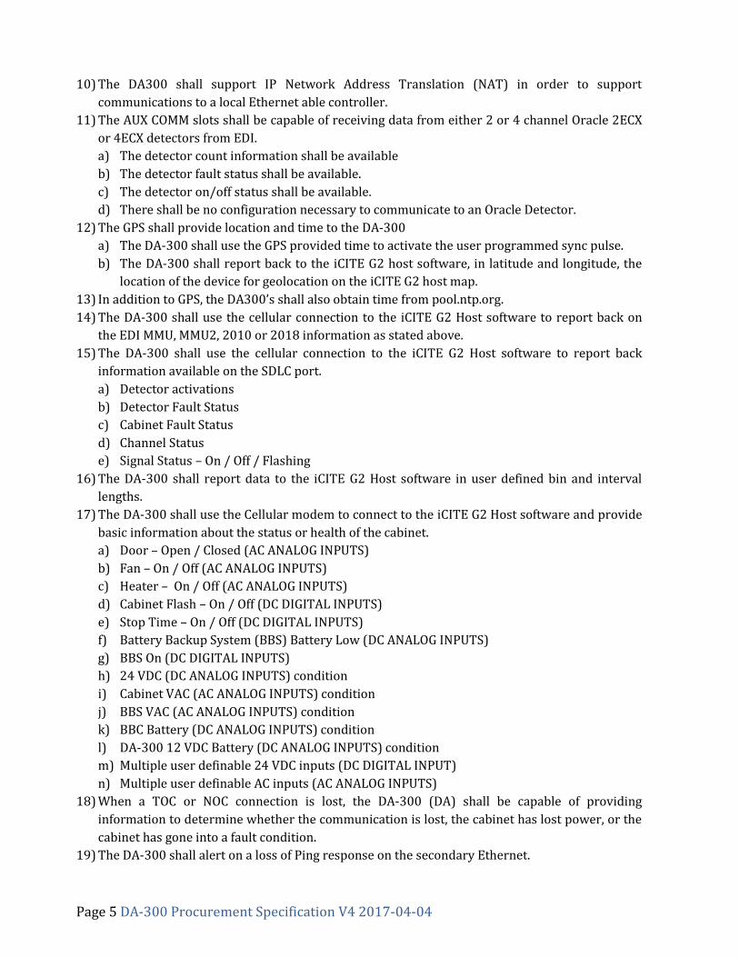
10) The DA300 shall support IP Network Address Translation (NAT) in order to support
communications to a local Ethernet able controller.
11) The AUX COMM slots shall be capable of receiving data from either 2 or 4 channel Oracle 2ECX
or 4ECX detectors from EDI.
a) The detector count information shall be available
b) The detector fault status shall be available.
c) The detector on/off status shall be available.
d) There shall be no configuration necessary to communicate to an Oracle Detector.
12) The GPS shall provide location and time to the DA-300
a) The DA-300 shall use the GPS provided time to activate the user programmed sync pulse.
b) The DA-300 shall report back to the iCITE G2 host software, in latitude and longitude, the
location of the device for geolocation on the iCITE G2 host map.
13) In addition to GPS, the DA300’s shall also obtain time from pool.ntp.org.
14) The DA-300 shall use the cellular connection to the iCITE G2 Host software to report back on
the EDI MMU, MMU2, 2010 or 2018 information as stated above.
15) The DA-300 shall use the cellular connection to the iCITE G2 Host software to report back
information available on the SDLC port.
a) Detector activations
b) Detector Fault Status
c) Cabinet Fault Status
d) Channel Status
e) Signal Status – On / Off / Flashing
16) The DA-300 shall report data to the iCITE G2 Host software in user defined bin and interval
lengths.
17) The DA-300 shall use the Cellular modem to connect to the iCITE G2 Host software and provide
basic information about the status or health of the cabinet.
a) Door – Open / Closed (AC ANALOG INPUTS)
b) Fan – On / Off (AC ANALOG INPUTS)
c) Heater – On / Off (AC ANALOG INPUTS)
d) Cabinet Flash – On / Off (DC DIGITAL INPUTS)
e) Stop Time – On / Off (DC DIGITAL INPUTS)
f) Battery Backup System (BBS) Battery Low (DC ANALOG INPUTS)
g) BBS On (DC DIGITAL INPUTS)
h) 24 VDC (DC ANALOG INPUTS) condition
i) Cabinet VAC (AC ANALOG INPUTS) condition
j) BBS VAC (AC ANALOG INPUTS) condition
k) BBC Battery (DC ANALOG INPUTS) condition
l) DA-300 12 VDC Battery (DC ANALOG INPUTS) condition
m) Multiple user definable 24 VDC inputs (DC DIGITAL INPUT)
n) Multiple user definable AC inputs (AC ANALOG INPUTS)
18) When a TOC or NOC connection is lost, the DA-300 (DA) shall be capable of providing
information to determine whether the communication is lost, the cabinet has lost power, or the
cabinet has gone into a fault condition.
19) The DA-300 shall alert on a loss of Ping response on the secondary Ethernet.

Page 6 DA-300 Procurement Specification V4 2017-04-04
20) TheDA-300 shall be capable of reporting by user defined intervals information regarding
hashed Wi-Fi MAC addresses identified at its location.
21) The DA-300 shall perform Data Compression in order to minimize cellular Data Package
limitations.
3) Cabinet interfaces The DA-300 is cabinet agnostic and shall be useable in the both NEMA TS-1 and TS-2 cabinets or hybrids thereof, as well as Caltrans 33X cabinets. 1) NEMA TS-1 cabinets
a) The interface to these cabinets shall be provided by detector inputs through the rear Digital
DC inputs
i) 16 inputs shall be designated for Vehicle detection
ii) 4 inputs shall be designated for Pedestrian inputs.
b) Phase colors and timing shall be provided through either an EDI or Reno A&E MMU via the
Ethernet or Serial port.
2) NEMA TS-2 cabinets
a) The primary interface for detections and phase color and timings shall be provided by the
SDLC connector.
b) Detector counts shall be provided through the Digital DC connector on the rear of the DA-
300
c) Additional information shall be provided via the Ethernet or Serial port of an EDI or Reno
A&E MMU.
3) Caltrans 33X cabinets.
a) The interface to these cabinets shall be provided by detector inputs through the rear Digital
DC inputs
i) 16 inputs shall be designated for Vehicle detection
ii) 4 inputs shall be designated for Pedestrian inputs.
b) Phase colors and timing shall be provided through either an EDI or Reno A&E 2018 via the
Ethernet or Serial port.
4) ATCC / ITS cabinets
a) Current versions of the DA-300 have not been developed for these cabinets and will not
communicate with the current ATCC components. In future versions this shall be available
with communications to both the CMU and controller via the SDLC buss.
b) The functionality shall be similar to the NEMA TS2 application which will also be able to
utilize the Oracle 2ECX or Oracle 4ECX detectors.
5) Non-Intrusive Signal State Data Acquisition for NEMA TS1 and 33X style Signal Cabinets. a) Signal state information shall be obtained in a way that does not interfere with the
Controller and its operations. b) Interconnect boxes such as those that intercept Controller commands and operations from
the MS or C1 connectors shall be prohibited. i) These interfaces introduce unnecessary multiple points of failure resulting in
misperception when diagnosing cabinet faults.
Page 7 DA-300 Procurement Specification V4 2017-04-04
c) Signal state information for these cabinet types shall be obtained from the Conflict Monitor via RS-232 or Ethernet connection.
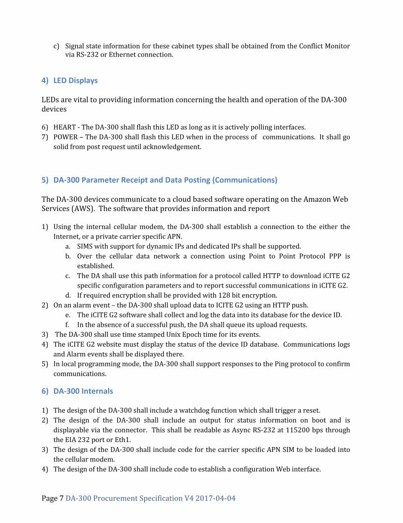
4) LED Displays LEDs are vital to providing information concerning the health and operation of the DA-300 devices 6) HEART - The DA-300 shall flash this LED as long as it is actively polling interfaces.
7) POWER – The DA-300 shall flash this LED when in the process of communications. It shall go
solid from post request until acknowledgement.
5) DA-300 Parameter Receipt and Data Posting (Communications) The DA-300 devices communicate to a cloud based software operating on the Amazon Web Services (AWS). The software that provides information and report 1) Using the internal cellular modem, the DA-300 shall establish a connection to the either the
Internet, or a private carrier specific APN.
a. SIMS with support for dynamic IPs and dedicated IPs shall be supported.
b. Over the cellular data network a connection using Point to Point Protocol PPP is
established.
c. The DA shall use this path information for a protocol called HTTP to download iCITE G2
specific configuration parameters and to report successful communications in iCITE G2.
d. If required encryption shall be provided with 128 bit encryption.
2) On an alarm event – the DA-300 shall upload data to ICITE G2 using an HTTP push.
e. The iCITE G2 software shall collect and log the data into its database for the device ID.
f. In the absence of a successful push, the DA shall queue its upload requests.
3) The DA-300 shall use time stamped Unix Epoch time for its events.
4) The iCITE G2 website must display the status of the device ID database. Communications logs
and Alarm events shall be displayed there.
5) In local programming mode, the DA-300 shall support responses to the Ping protocol to confirm
communications.
6) DA-300 Internals
1) The design of the DA-300 shall include a watchdog function which shall trigger a reset.
2) The design of the DA-300 shall include an output for status information on boot and is
displayable via the connector. This shall be readable as Async RS-232 at 115200 bps through
the EIA 232 port or Eth1.
3) The design of the DA-300 shall include code for the carrier specific APN SIM to be loaded into
the cellular modem.
4) The design of the DA-300 shall include code to establish a configuration Web interface.
Page 8 DA-300 Procurement Specification V4 2017-04-04
5) In local programming mode the DA-300 shall support the SSH / FTP protocol for file transfer.
6) In local programming mode, the DA-300 shall support the ability for FTP to display access
rights.
7) System Security
1) In local programming mode, the DA-300 shall require a password for SSH / FTP access.
2) A carrier APN is recommended along with cost tracking plans.
3) The iCITE G2 software shall be setup with firewalls to limit remote desktop access.
4) The iCITE G2 software user passwords shall be individual by organization.
5) DA-300 SQL database access is only allowed by EDI/RENO, reporting shall be setup in advance.
6) The system shall be capable of using MAC address identification as an additional security
measurement. This is to prevent rogue devices from being installed
7) The system shall provide 128 bit encryption for all data that is provided by DA hardware to
iCITE G2.
8) The system shall be password protected and have three (4) software levels including but not
limited to as “Administrator”, “Read/Write”, “Read only”, “Limited Read”.
a. A minimum level of security for password choices shall be required.
9) Passwords must be diverse, (e.g. can’t use “password”, “123”, carriage return)
10) If a DA with an unknown ID is setup the data shall NOT be posted and shall be ignored.
11) If multiple DA’s are setup with common ID’s the data shall be captured.
8) iCITE G2 Diagnostic Information
1) If the post of information to iCITE G2 is not successful, the DA-300 shall log a message to its
diagnostic port, queue the file for the next transmission, and iCITE G2 host shall log a time
stamp entry “Server check-in failed. Retry Attempt #”.
2) If the post of information is not successful for 3 attempts, iCITE G2 host shall log a time stamp
entry “Server check-in failed on 3 consecutive retries, checking connections”.
3) If a “Soft Reset” has occurred, a time stamped entry is displayed in the Error Log for that DA
unit.
4) If a “Hard Reset” has occurred, a time stamped entry is displayed in the Error Log for that DA
unit.
5) Each Configuration sent and each dataset post shall have its own time stamped communication
log entry in iCITE G2.
9) SQL Structured Query Language Data Extraction
1) The system shall allow for DA-300 time stamped data to be extracted using the device id as a
key to the database maintained in iCITE G2.
2) Database security shall require individual passwords to allow users to access the data.
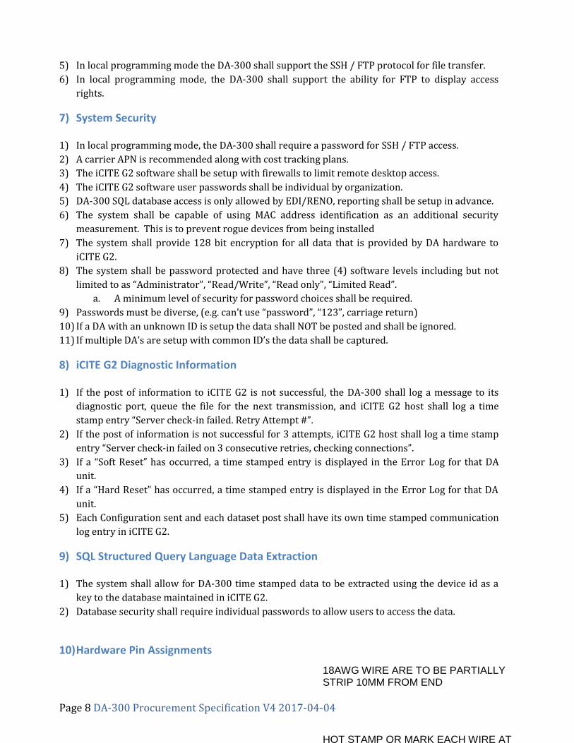
10) Hardware Pin Assignments
18AWG WIRE ARE TO BE PARTIALLY STRIP 10MM FROM END
HOT STAMP OR MARK EACH WIRE AT
Page 9 DA-300 Procurement Specification V4 2017-04-04
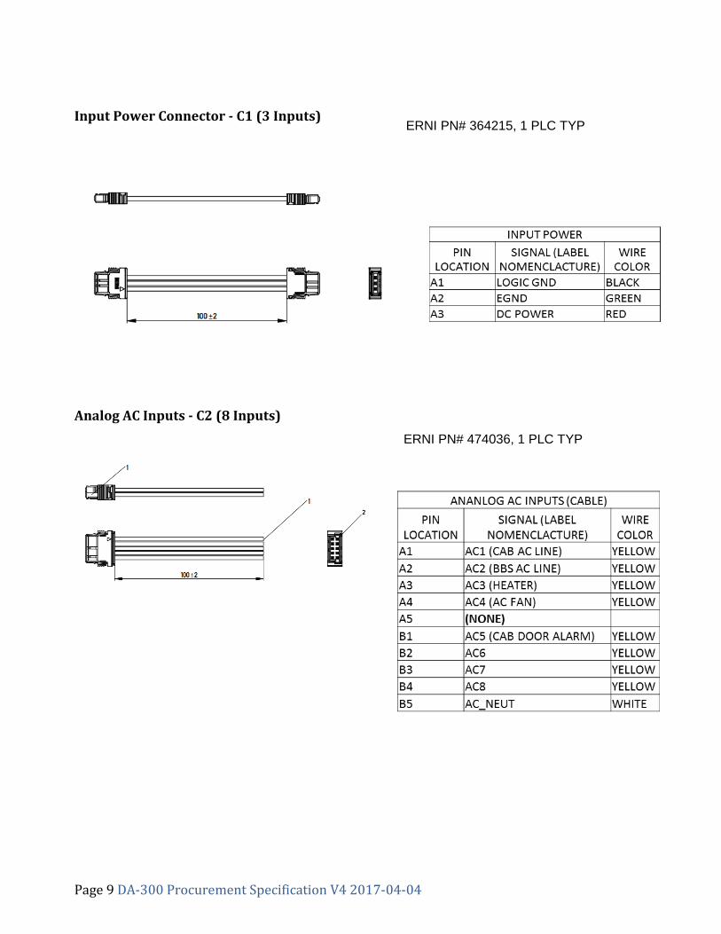
Input Power Connector - C1 (3 Inputs)
Analog AC Inputs - C2 (8 Inputs)
ERNI PN# 364215, 1 PLC TYP
ERNI PN# 474036, 1 PLC TYP
Page 10 DA-300 Procurement Specification V4 2017-04-04
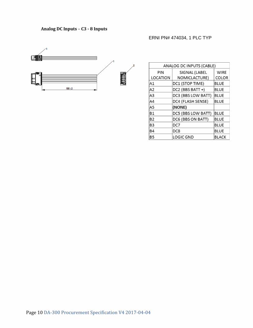
Analog DC Inputs – C3 - 8 Inputs
ERNI PN# 474034, 1 PLC TYP
Page 11 DA-300 Procurement Specification V4 2017-04-04
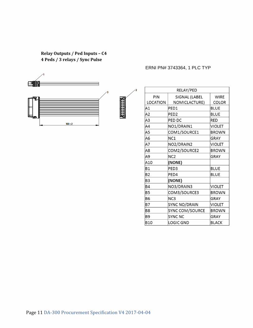
Relay Outputs / Ped Inputs – C4
4 Peds / 3 relays / Sync Pulse
ERNI PN# 3743364, 1 PLC TYP
Page 12 DA-300 Procurement Specification V4 2017-04-04
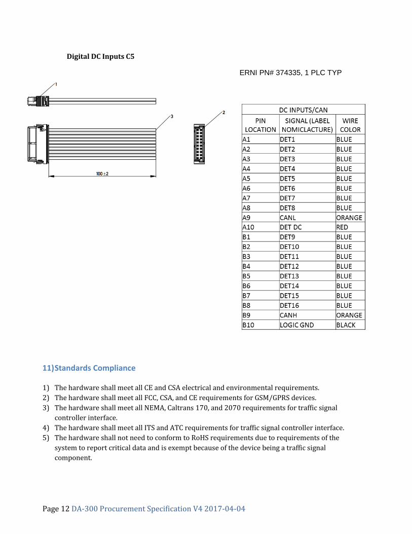
Digital DC Inputs C5
11) Standards Compliance
1) The hardware shall meet all CE and CSA electrical and environmental requirements.
2) The hardware shall meet all FCC, CSA, and CE requirements for GSM/GPRS devices.
3) The hardware shall meet all NEMA, Caltrans 170, and 2070 requirements for traffic signal
controller interface.
4) The hardware shall meet all ITS and ATC requirements for traffic signal controller interface.
5) The hardware shall not need to conform to RoHS requirements due to requirements of the
system to report critical data and is exempt because of the device being a traffic signal
component.
ERNI PN# 374335, 1 PLC TYP