Embed Size (px)
Citation preview
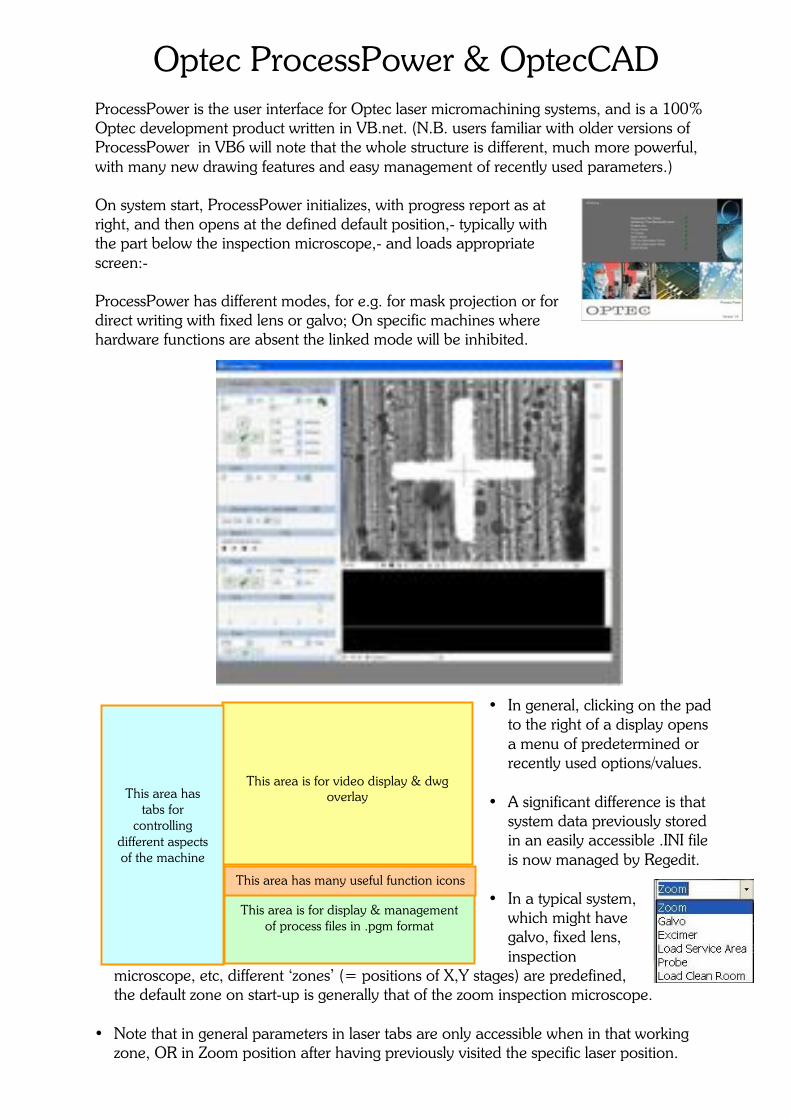
Optec ProcessPower & OptecCAD ProcessPower is the user interface for Optec laser micromachining systems, and is a 100% Optec development product written in VB.net. (N.B. users familiar with older versions of ProcessPower in VB6 will note that the whole structure is different, much more powerful, with many new drawing features and easy management of recently used parameters.) On system start, ProcessPower initializes, with progress report as at right, and then opens at the defined default position,- typically with the part below the inspection microscope,- and loads appropriate screen:- ProcessPower has different modes, for e.g. for mask projection or for direct writing with fixed lens or galvo; On specific machines where hardware functions are absent the linked mode will be inhibited.
• In general, clicking on the pad to the right of a display opens a menu of predetermined or recently used options/values.
• A significant difference is that
system data previously stored in an easily accessible .INI file is now managed by Regedit.
• In a typical system,
which might have galvo, fixed lens, inspection
microscope, etc, different ‘zones’ (= positions of X,Y stages) are predefined, the default zone on start-up is generally that of the zoom inspection microscope.
• Note that in general parameters in laser tabs are only accessible when in that working
zone, OR in Zoom position after having previously visited the specific laser position.
This area is for video display & dwg overlay
This area is for display & management
of process files in .pgm format
This area has many useful function icons
This area has
tabs for controlling
different aspects of the machine
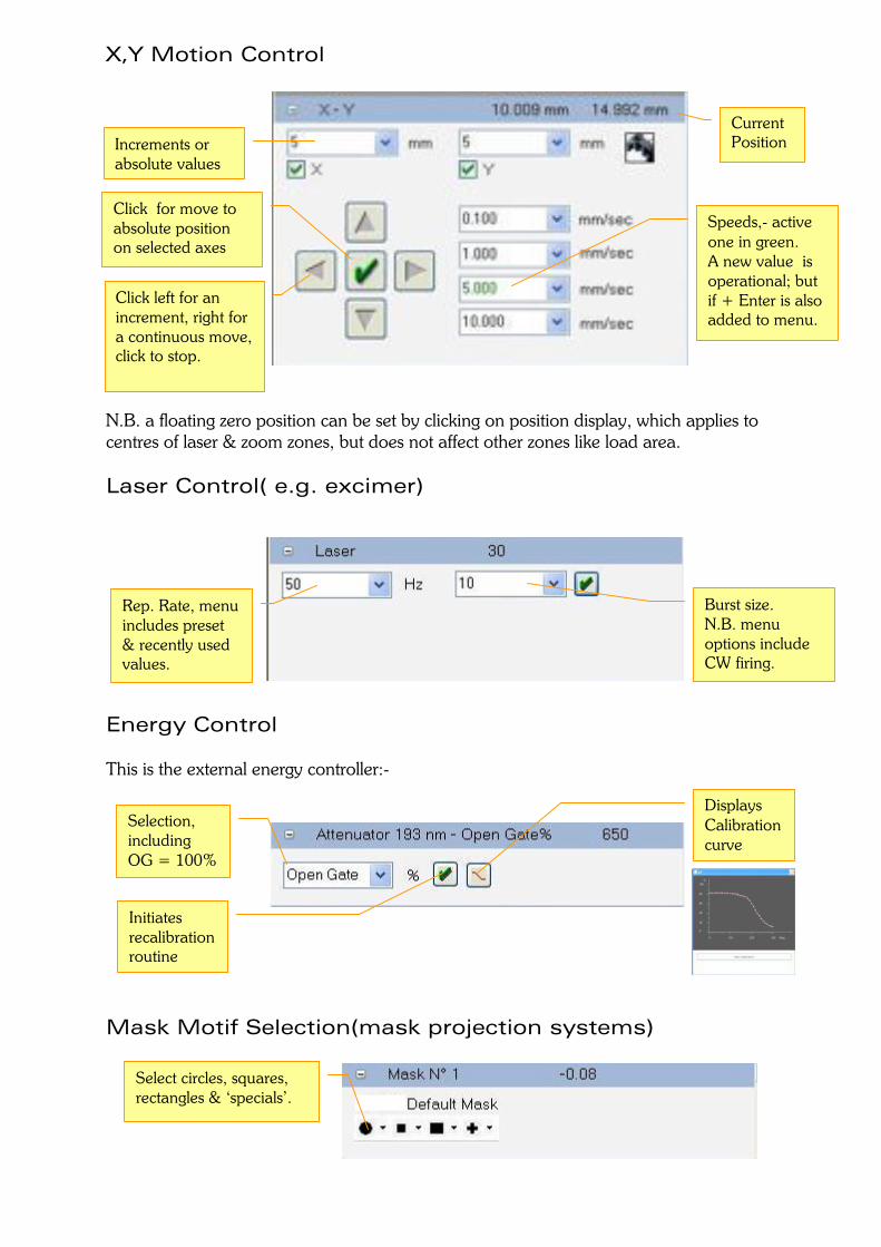
X,Y Motion Control
N.B. a floating zero position can be set by clicking on position display, which applies to centres of laser & zoom zones, but does not affect other zones like load area. Laser Control( e.g. excimer) Energy Control This is the external energy controller:- Mask Motif Selection(mask projection systems)
Speeds,- active one in green. A new value is operational; but if + Enter is also added to menu.
Click left for an increment, right for a continuous move, click to stop.
Increments or absolute values
Click for move to absolute position on selected axes
Current Position
Burst size. N.B. menu options include CW firing.
Rep. Rate, menu includes preset & recently used values.
Displays Calibration curve
Initiates recalibration routine
Selection, including OG = 100%
Select circles, squares, rectangles & ‘specials’.
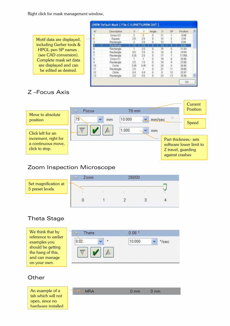
Right click for mask management window, Z –Focus Axis Zoom Inspection Microscope Theta Stage Other
Motif data are displayed, including Gerber tools & HPGL pen SP names . (see CAD conversion).
Complete mask set data are displayed and can be edited as desired.
Speed
Click left for an increment, right for a continuous move, click to stop.
Current Position
Move to absolute position
Part thickness;- sets software lower limit to Z travel, guarding against crashes
Set magnification at 5 preset levels.
We think that by reference to earlier examples you should be getting the hang of this, and can manage on your own.
An example of a tab which will not open, since no hardware installed
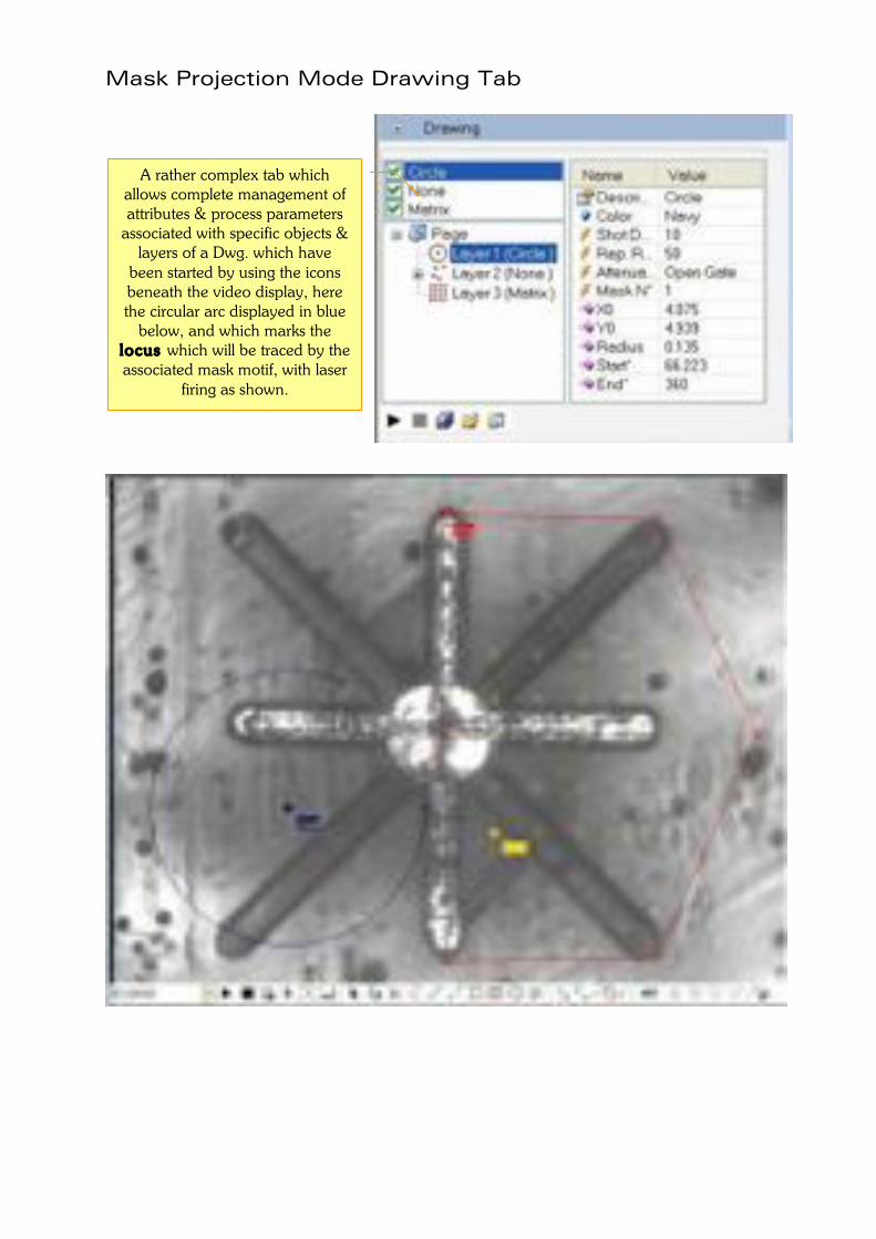
Mask Projection Mode Drawing Tab
A rather complex tab which allows complete management of attributes & process parameters
associated with specific objects & layers of a Dwg. which have
been started by using the icons beneath the video display, here the circular arc displayed in blue
below, and which marks the locus which will be traced by the associated mask motif, with laser
firing as shown.
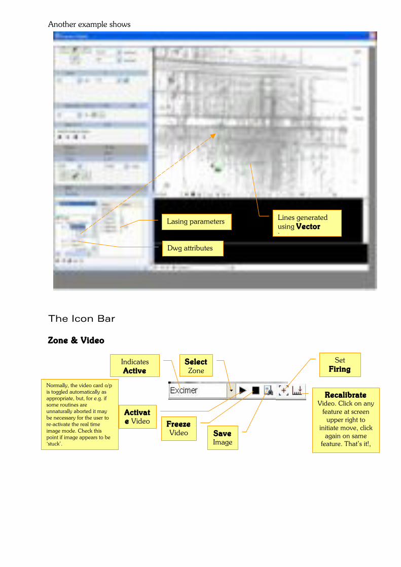
Another example shows
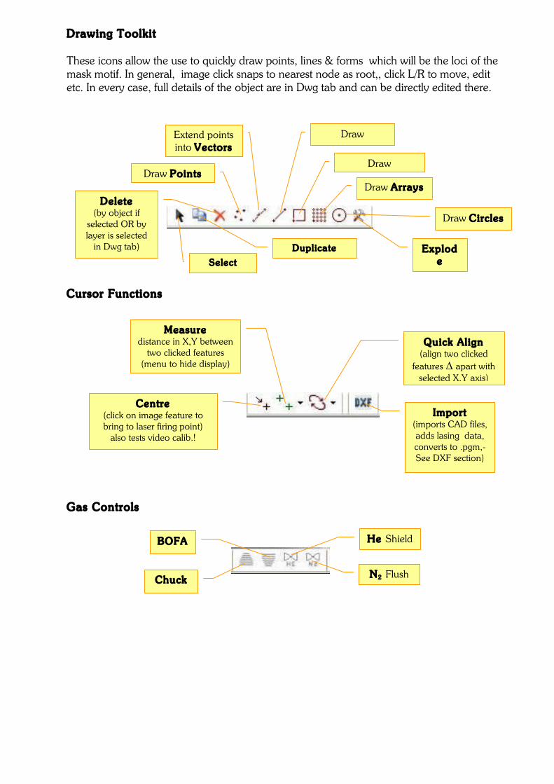
The Icon Bar Zone & Video
Indicates Active Zone
Select Zone
Activate Video Freeze
Video Save Image
Recalibrate Video. Click on any
feature at screen upper right to
initiate move, click again on same
feature. That’s it!,
Set Fir ing Point
Lasing parameters
Dwg attributes
Lines generated using Vector icon
Normally, the video card o/p is toggled automatically as appropriate, but, for e.g. if some routines are unnaturally aborted it may be necessary for the user to re-activate the real time image mode. Check this point if image appears to be ‘stuck’.
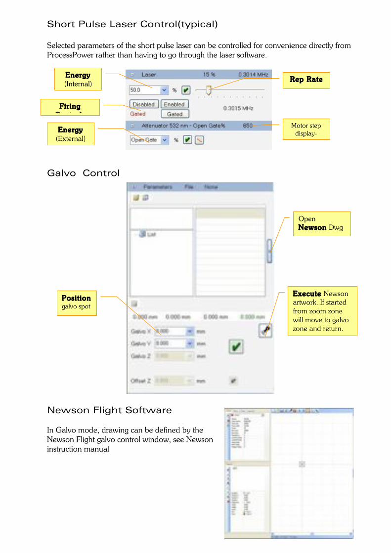
Drawing Toolkit These icons allow the use to quickly draw points, lines & forms which will be the loci of the mask motif. In general, image click snaps to nearest node as root,, click L/R to move, edit etc. In every case, full details of the object are in Dwg tab and can be directly edited there.
Cursor Functions
Gas Controls
Delete (by object if
selected OR by layer is selected
in Dwg tab)
Draw Points
Extend points into Vectors
Draw Polyl ines
Draw Circles
Draw Arrays
Draw Rectangles
Explode
(array) Select object
Duplicate object
Centre (click on image feature to bring to laser firing point)
also tests video calib.!
Measure distance in X,Y between
two clicked features (menu to hide display)
Quick Align (align two clicked
features Δ apart with selected X,Y axis)
Import (imports CAD files, adds lasing data, converts to .pgm,- See DXF section)
Chuck
BOFA He Shield
N2 Flush
Short Pulse Laser Control(typical) Selected parameters of the short pulse laser can be controlled for convenience directly from ProcessPower rather than having to go through the laser software.
Galvo Control
Newson Flight Software In Galvo mode, drawing can be defined by the Newson Flight galvo control window, see Newson instruction manual
Rep Rate
Energy (External)
Fir ing Controls
Motor step display-
Energy (Internal)
Posit ion galvo spot
Execute Newson artwork. If started from zoom zone will move to galvo zone and return.
Open Newson Dwg window
DXF Conversion (using X,Y stages) This conversion routine takes .dxf data, allows the user to add laser firing data, and converts to machine language. The routine is intended to be used with motion from the X,Y stages(rather than galvo), and can handle both single motifs(focal point lasers) and mask based systems where mask motif is determined by pen colour in the original dwg. 1. The .dxf file must be saved from AutoCad in version 14 or later. 2. In .dxf files, individual segments of lines & circles etc. are considered as ‘objects’, and
will be referred to as such in what follows. 3. The coordinate data associated with the object is used to direct the X,Y motion,
tracking from start to finish of the segment. Thus in mask projection systems, the track marks the locus of the motif centre; the actual area processed will depend on the motif size, and is not displayed automatically by the CAD program, though can of course be drawn for convenience in another layer(not to be processed)
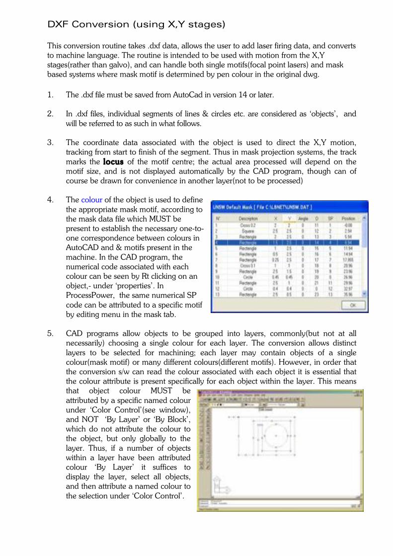
4. The colour of the object is used to define
the appropriate mask motif, according to the mask data file which MUST be present to establish the necessary one-to-one correspondence between colours in AutoCAD and & motifs present in the machine. In the CAD program, the numerical code associated with each colour can be seen by Rt clicking on an object,- under ‘properties’. In ProcessPower, the same numerical SP code can be attributed to a specific motif by editing menu in the mask tab.
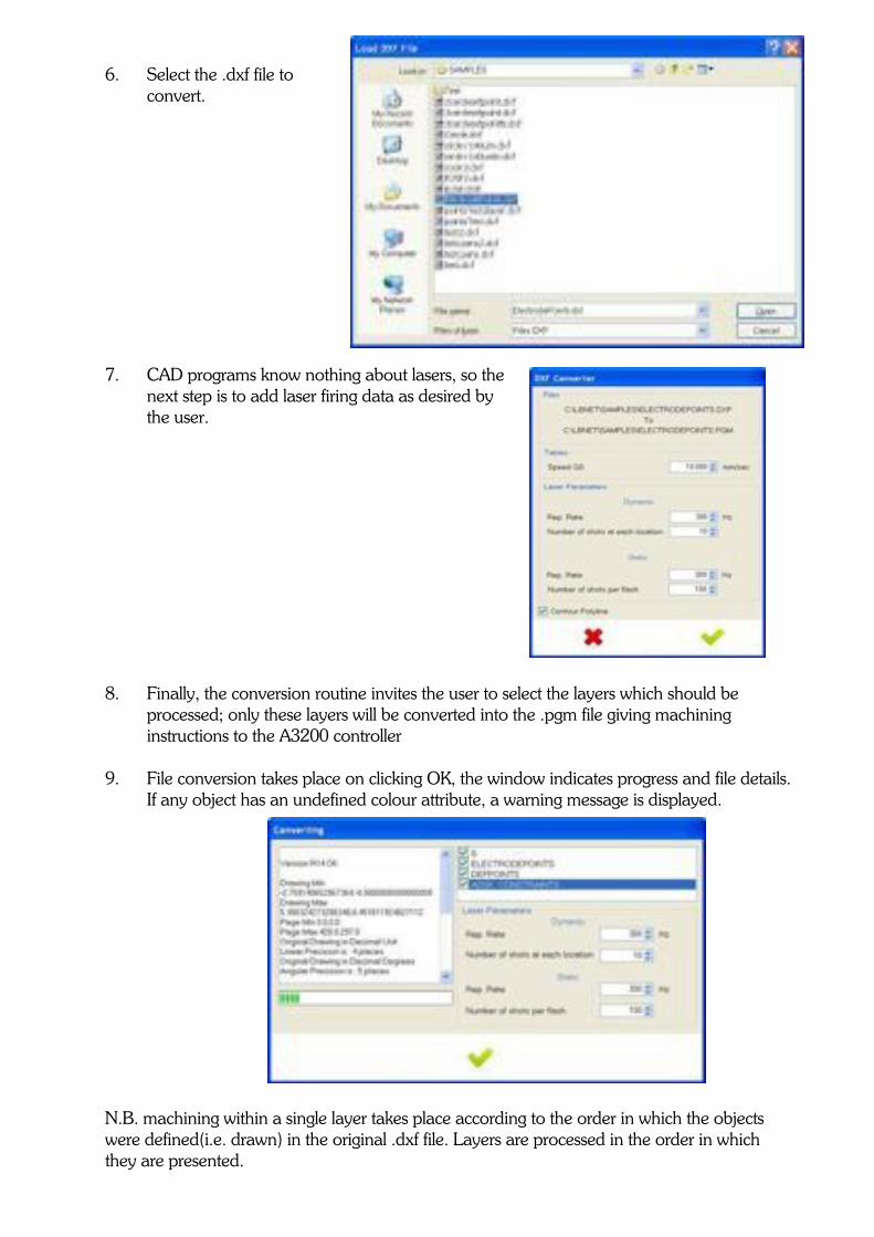
5. CAD programs allow objects to be grouped into layers, commonly(but not at all
necessarily) choosing a single colour for each layer. The conversion allows distinct layers to be selected for machining; each layer may contain objects of a single colour(mask motif) or many different colours(different motifs). However, in order that the conversion s/w can read the colour associated with each object it is essential that the colour attribute is present specifically for each object within the layer. This means that object colour MUST be attributed by a specific named colour under ‘Color Control’(see window), and NOT ‘By Layer’ or ‘By Block’, which do not attribute the colour to the object, but only globally to the layer. Thus, if a number of objects within a layer have been attributed colour ‘By Layer’ it suffices to display the layer, select all objects, and then attribute a named colour to the selection under ‘Color Control’.
6. Select the .dxf file to
convert.
7. CAD programs know nothing about lasers, so the next step is to add laser firing data as desired by the user.
8. Finally, the conversion routine invites the user to select the layers which should be
processed; only these layers will be converted into the .pgm file giving machining instructions to the A3200 controller
9. File conversion takes place on clicking OK, the window indicates progress and file details.
If any object has an undefined colour attribute, a warning message is displayed.
N.B. machining within a single layer takes place according to the order in which the objects were defined(i.e. drawn) in the original .dxf file. Layers are processed in the order in which they are presented.
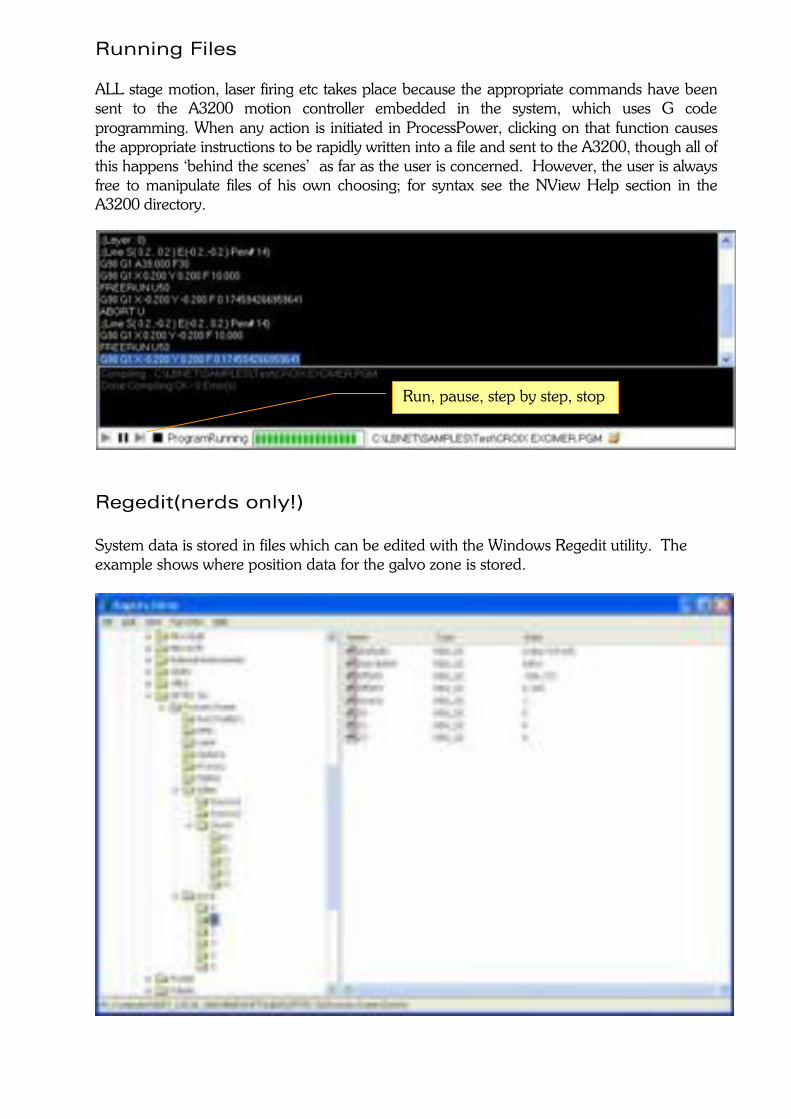
Running Files ALL stage motion, laser firing etc takes place because the appropriate commands have been sent to the A3200 motion controller embedded in the system, which uses G code programming. When any action is initiated in ProcessPower, clicking on that function causes the appropriate instructions to be rapidly written into a file and sent to the A3200, though all of this happens ‘behind the scenes’ as far as the user is concerned. However, the user is always free to manipulate files of his own choosing; for syntax see the NView Help section in the A3200 directory.
Regedit(nerds only!) System data is stored in files which can be edited with the Windows Regedit utility. The example shows where position data for the galvo zone is stored.
Run, pause, step by step, stop
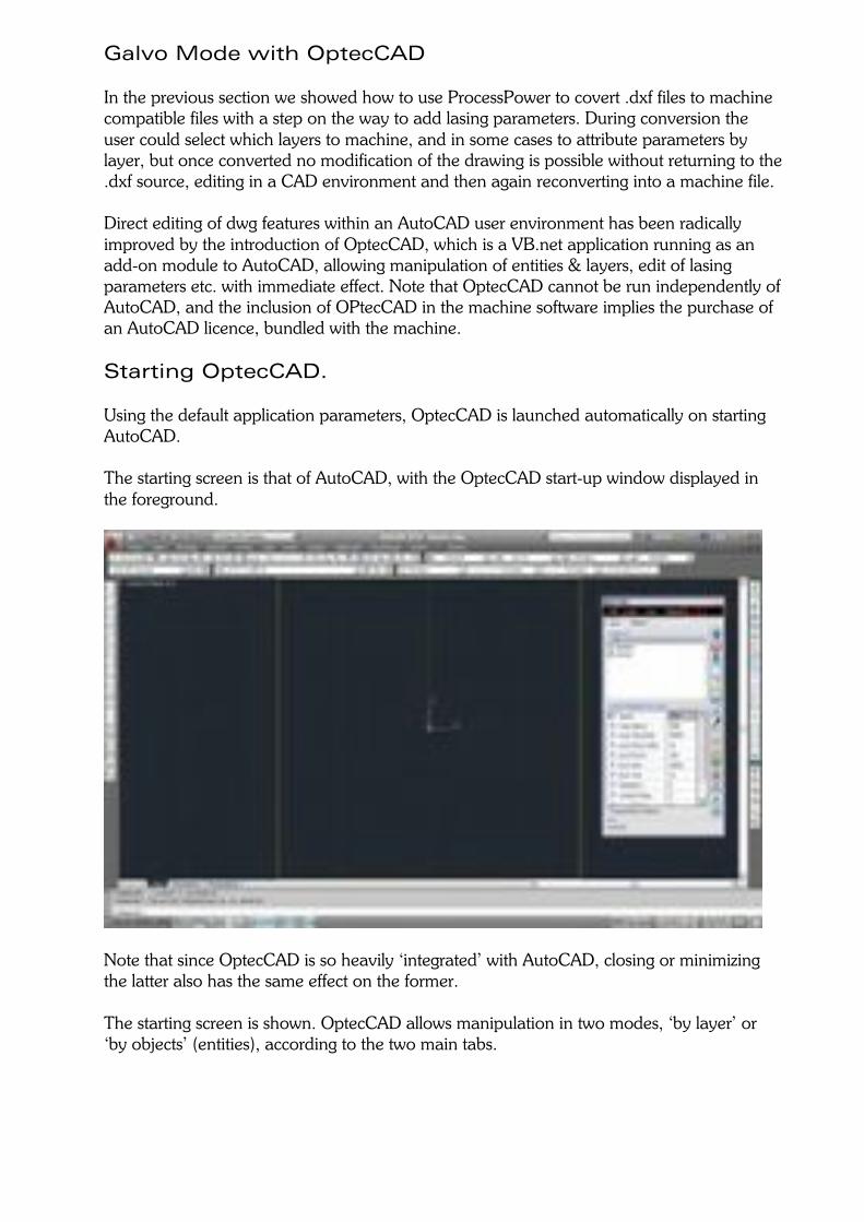
Galvo Mode with OptecCAD In the previous section we showed how to use ProcessPower to covert .dxf files to machine compatible files with a step on the way to add lasing parameters. During conversion the user could select which layers to machine, and in some cases to attribute parameters by layer, but once converted no modification of the drawing is possible without returning to the .dxf source, editing in a CAD environment and then again reconverting into a machine file. Direct editing of dwg features within an AutoCAD user environment has been radically improved by the introduction of OptecCAD, which is a VB.net application running as an add-on module to AutoCAD, allowing manipulation of entities & layers, edit of lasing parameters etc. with immediate effect. Note that OptecCAD cannot be run independently of AutoCAD, and the inclusion of OPtecCAD in the machine software implies the purchase of an AutoCAD licence, bundled with the machine. Starting OptecCAD. Using the default application parameters, OptecCAD is launched automatically on starting AutoCAD. The starting screen is that of AutoCAD, with the OptecCAD start-up window displayed in the foreground.
Note that since OptecCAD is so heavily ‘integrated’ with AutoCAD, closing or minimizing the latter also has the same effect on the former. The starting screen is shown. OptecCAD allows manipulation in two modes, ‘by layer’ or ‘by objects’ (entities), according to the two main tabs.
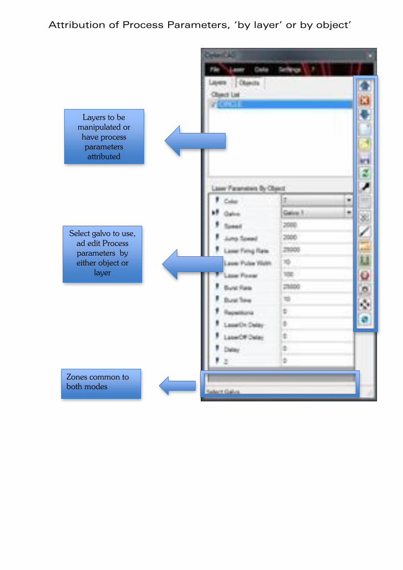
Attribution of Process Parameters, ‘by layer’ or by object’
Layers to be manipulated or have process parameters attributed
Zones common to both modes
Select galvo to use, ad edit Process parameters by either object or
layer
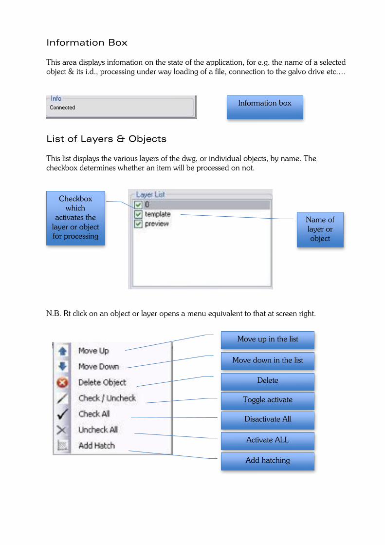
Information Box This area displays infomation on the state of the application, for e.g. the name of a selected object & its i.d., processing under way loading of a file, connection to the galvo drive etc.…
List of Layers & Objects This list displays the various layers of the dwg, or individual objects, by name. The checkbox determines whether an item will be processed on not.
N.B. Rt click on an object or layer opens a menu equivalent to that at screen right.
Move up in the list
Move down in the list
Delete
Name of layer or object
Checkbox which
activates the layer or object for processing
Toggle activate
Activate ALL
Disactivate All
Add hatching
Information box
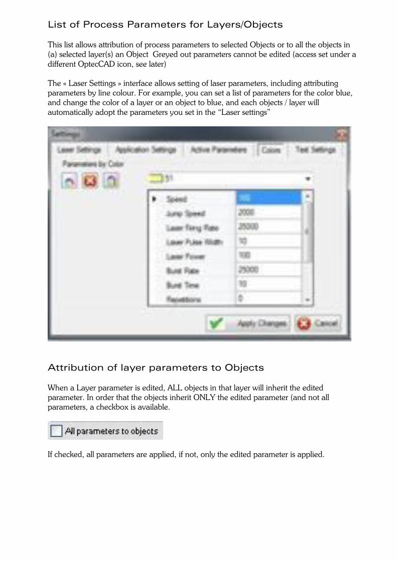
List of Process Parameters for Layers/Objects This list allows attribution of process parameters to selected Objects or to all the objects in (a) selected layer(s) an Object Greyed out parameters cannot be edited (access set under a different OptecCAD icon, see later) The « Laser Settings » interface allows setting of laser parameters, including attributing parameters by line colour. For example, you can set a list of parameters for the color blue, and change the color of a layer or an object to blue, and each objects / layer will automatically adopt the parameters you set in the “Laser settings”
Attribution of layer parameters to Objects When a Layer parameter is edited, ALL objects in that layer will inherit the edited parameter. In order that the objects inherit ONLY the edited parameter (and not all parameters, a checkbox is available.
If checked, all parameters are applied, if not, only the edited parameter is applied.
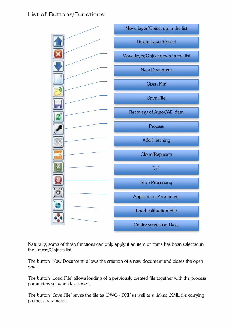
List of Buttons/Functions
Naturally, some of these functions can only apply if an item or items has been selected in the Layers/Objects list The button ‘New Document’ allows the creation of a new document and closes the open one. The button ‘Load File’ allows loading of a previously created file together with the process parameters set when last saved. The button ‘Save File’ saves the file as DWG / DXF as well as a linked .XML file carrying procress parameters.
Delete Layer/Object
Move layer/Object up in the list
Move layer/Object down in the list New Document
Open File
Save File
Recovery of AutoCAD data
Process
Add Hatching
Clone/Replicate
Drill
Stop Processing
Application Parameters
Load calibration File
Centre screen on Dwg.
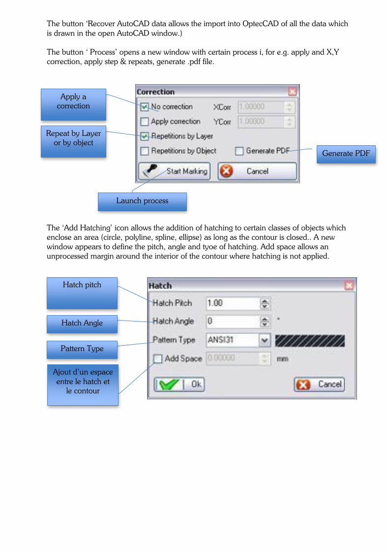
Hatch pitch
Hatch Angle
Pattern Type
Ajout d’un espace entre le hatch et
le contour
The button ‘Recover AutoCAD data allows the import into OptecCAD of all the data which is drawn in the open AutoCAD window.) The button ‘ Process’ opens a new window with certain process i, for e.g. apply and X,Y correction, apply step & repeats, generate .pdf file.
The ‘Add Hatching’ icon allows the addition of hatching to certain classes of objects which enclose an area (circle, polyline, spline, ellipse) as long as the contour is closed.. A new window appears to define the pitch, angle and tyoe of hatching. Add space allows an unprocessed margin around the interior of the contour where hatching is not applied.
Apply a correction
Repeat by Layer or by object
Generate PDF
Launch process
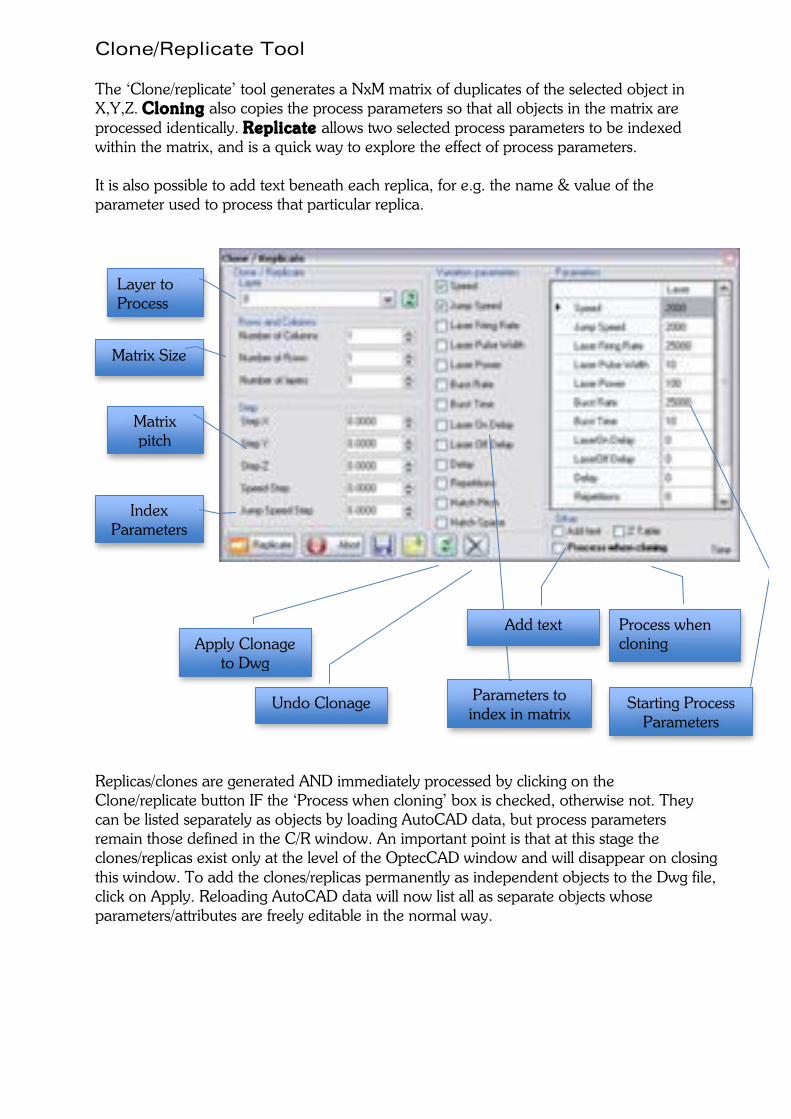
Clone/Replicate Tool The ‘Clone/replicate’ tool generates a NxM matrix of duplicates of the selected object in X,Y,Z. Cloning also copies the process parameters so that all objects in the matrix are processed identically. Replicate allows two selected process parameters to be indexed within the matrix, and is a quick way to explore the effect of process parameters. It is also possible to add text beneath each replica, for e.g. the name & value of the parameter used to process that particular replica. Replicas/clones are generated AND immediately processed by clicking on the Clone/replicate button IF the ‘Process when cloning’ box is checked, otherwise not. They can be listed separately as objects by loading AutoCAD data, but process parameters remain those defined in the C/R window. An important point is that at this stage the clones/replicas exist only at the level of the OptecCAD window and will disappear on closing this window. To add the clones/replicas permanently as independent objects to the Dwg file, click on Apply. Reloading AutoCAD data will now list all as separate objects whose parameters/attributes are freely editable in the normal way.
Layer to Process
Matrix Size
Matrix pitch
Parameters to index in matrix
Starting Process Parameters
Add text
Index Parameters
Undo Clonage
Apply Clonage to Dwg
Process when cloning
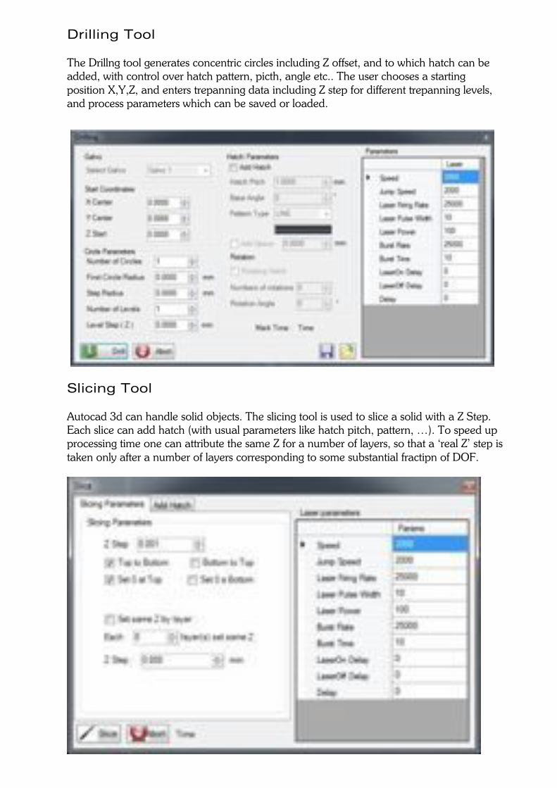
Drilling Tool The Drillng tool generates concentric circles including Z offset, and to which hatch can be added, with control over hatch pattern, picth, angle etc.. The user chooses a starting position X,Y,Z, and enters trepanning data including Z step for different trepanning levels, and process parameters which can be saved or loaded.
Slicing Tool Autocad 3d can handle solid objects. The slicing tool is used to slice a solid with a Z Step. Each slice can add hatch (with usual parameters like hatch pitch, pattern, …). To speed up processing time one can attribute the same Z for a number of layers, so that a ‘real Z’ step is taken only after a number of layers corresponding to some substantial fractipn of DOF.
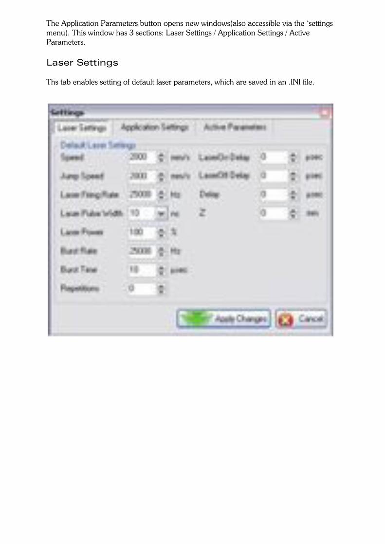
The Application Parameters button opens new windows(also accessible via the ‘settings menu). This window has 3 sections: Laser Settings / Application Settings / Active Parameters. Laser Settings Ths tab enables setting of default laser parameters, which are saved in an .INI file.
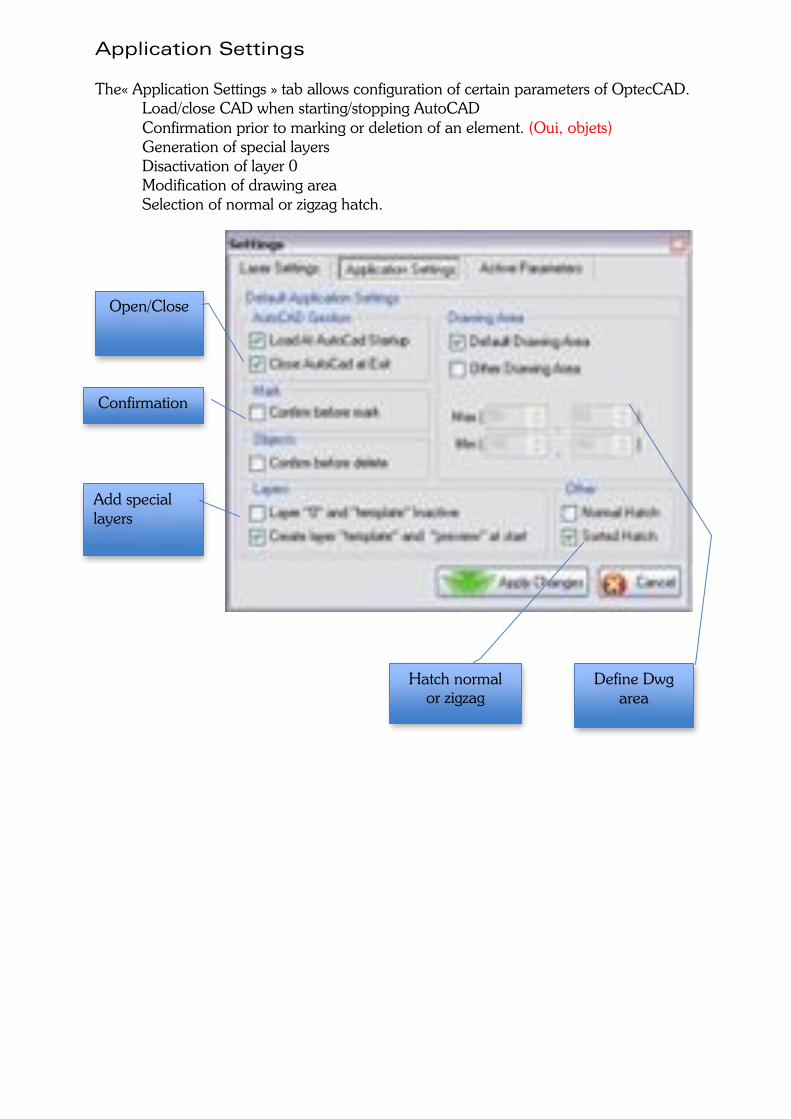
Application Settings The« Application Settings » tab allows configuration of certain parameters of OptecCAD. Load/close CAD when starting/stopping AutoCAD Confirmation prior to marking or deletion of an element. (Oui, objets) Generation of special layers
Disactivation of layer 0 Modification of drawing area Selection of normal or zigzag hatch.
Confirmation
Define Dwg area
Open/Close
Add special layers
Hatch normal or zigzag
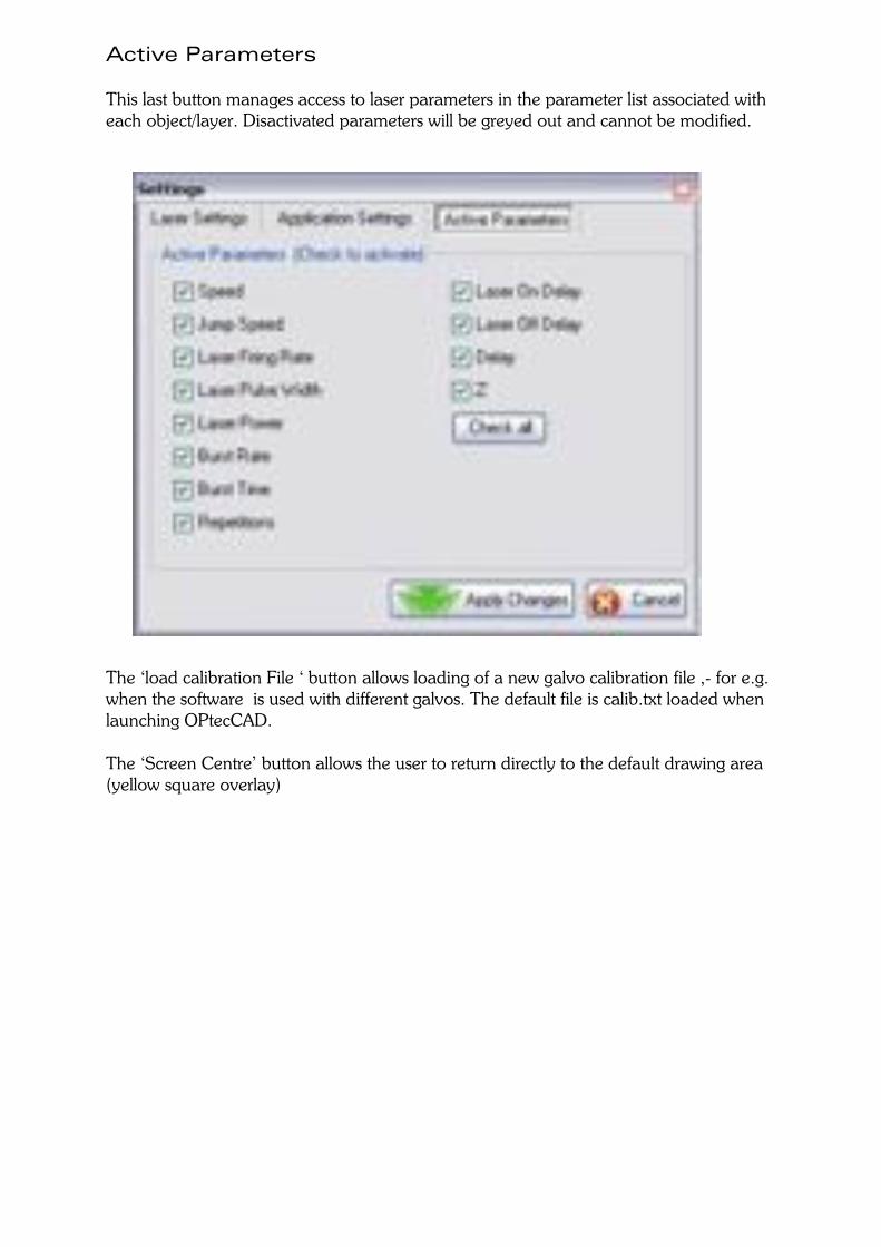
Active Parameters This last button manages access to laser parameters in the parameter list associated with each object/layer. Disactivated parameters will be greyed out and cannot be modified. The ‘load calibration File ‘ button allows loading of a new galvo calibration file ,- for e.g. when the software is used with different galvos. The default file is calib.txt loaded when launching OPtecCAD. The ‘Screen Centre’ button allows the user to return directly to the default drawing area (yellow square overlay)