Embed Size (px)
Citation preview
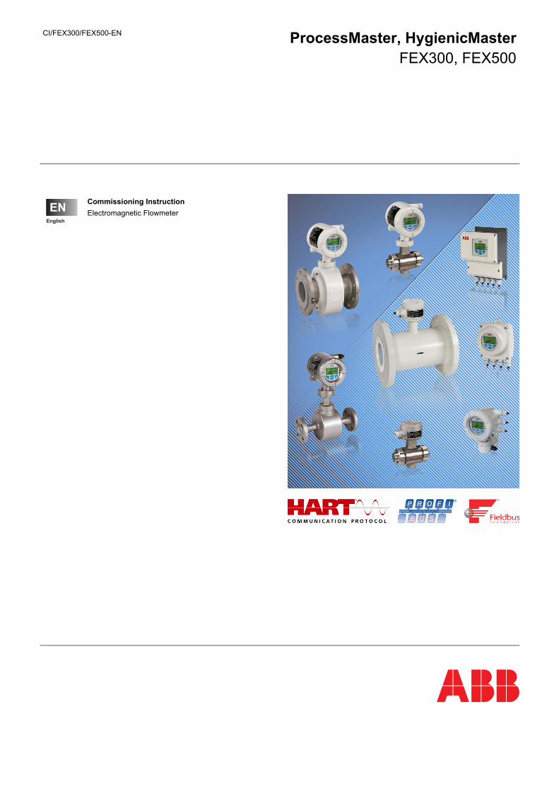
CI/FEX300/FEX500-EN ProcessMaster, HygienicMaster FEX300, FEX500
Commissioning Instruction
Electromagnetic Flowmeter


CI/FEX300/FEX500-EN FEX300, FEX500 EN - 1
Neu
Electromagnetic Flowmeter ProcessMaster, HygienicMaster FEX300, FEX500
Commissioning Instruction - EN CI/FEX300/FEX500-EN
02.2018
Rev. G
Translation of the original instruction
Manufacturer:
ABB Automation Products GmbH Measurement & Analytics
Dransfelder Straße 2 D-37079 Göttingen Germany Tel.: +49 551 905-0 Fax: +49 551 905-777
Customer service center
Phone: +49 180 5 222 580 Fax: +49 621 381 931-29031 [email protected]
ABB Inc. Measurement & Analytics
125 E. County Line Road Warminster, PA 18974 USA Tel.: +1 215 674 6000 Fax: +1 215 674 7183
ABB Engineering (Shanghai) Ltd. Measurement & Analytics
No. 4528, Kangxin Highway, Pudong New District, Shanghai, 201319, P.R. China Tel.: +86(0) 21 6105 6666 Fax: +86(0) 21 6105 6677 Mail: [email protected]
© Copyright 2018 by ABB Automation Products GmbH Subject to changes without notice
This document is protected by copyright. It assists the user in safe and efficient operation of the device. The contents of this document, whether whole or in part, may not be copied or reproduced without prior approval by the copyright holder.
Contents
Contents
2 - EN FEX300, FEX500 CI/FEX300/FEX500-EN
1 Safety .................................................................................................................................................................... 5
1.1 General information and notes for the reader ................................................................................................ 5
1.2 Intended use ................................................................................................................................................... 6
1.3 Improper use .................................................................................................................................................. 6
1.4 Target groups and qualifications .................................................................................................................... 6
1.5 Plates and symbols ........................................................................................................................................ 7
1.5.1 Safety- / warning symbols, note symbols ................................................................................................ 7
1.6 Transport safety information .......................................................................................................................... 8
1.7 Installation safety information ......................................................................................................................... 8
1.8 Safety instructions for electrical installation ................................................................................................... 8
1.9 Safety instructions for operation ..................................................................................................................... 9
1.10 Technical limit values ..................................................................................................................................... 9
1.11 Allowed measuring media .............................................................................................................................. 9
1.12 Returning devices ......................................................................................................................................... 10
1.13 Disposal ........................................................................................................................................................ 10
1.13.1 Information on WEEE Directive 2012/19/EU (Waste Electrical and Electronic Equipment) ................. 10
2 Device designs .................................................................................................................................................. 11
2.1.1 Integral mount design ............................................................................................................................ 11
2.1.2 Remote mount design ........................................................................................................................... 12
3 Transport ............................................................................................................................................................ 13
3.1 Inspection ..................................................................................................................................................... 13
3.2 Transport of flanged units smaller than DN 450 .......................................................................................... 13
3.3 Transport of flanged units larger than DN 400 ............................................................................................. 13
4 Mounting ............................................................................................................................................................ 14
4.1 General information on installation ............................................................................................................... 14
4.1.1 Supports for meter sizes larger than DN 400 ........................................................................................ 14
4.1.2 Selecting gaskets .................................................................................................................................. 15
4.1.3 Devices with a wafer-type design ......................................................................................................... 15
4.1.4 Installing the meter tube ........................................................................................................................ 16
4.2 Torque information ....................................................................................................................................... 17
4.3 Information on 3A conformity ....................................................................................................................... 21
4.4 Installation Requirements ............................................................................................................................. 22
4.4.1 Flow direction ........................................................................................................................................ 22
4.4.2 Electrode axis ........................................................................................................................................ 22
4.4.3 In- and outlet pipe sections ................................................................................................................... 22
4.4.4 Vertical connections .............................................................................................................................. 22
4.4.5 Horizontal connections .......................................................................................................................... 22
4.4.6 Free inlet or outlet ................................................................................................................................. 22
4.4.7 Strongly contaminated measuring media .............................................................................................. 22
4.4.8 Installation in the vicinity of pumps ....................................................................................................... 23
4.4.9 Installation of the high temperature design ........................................................................................... 23
4.4.10 Devices with extended diagnostic functions ......................................................................................... 23
4.4.11 Minimum distance ................................................................................................................................. 23
4.4.12 Installation in pipelines with larger nominal diameters .......................................................................... 23
4.5 Ground.......................................................................................................................................................... 24
4.5.1 General information on ground connections ......................................................................................... 24
4.5.2 Metal pipe with fixed flanges ................................................................................................................. 24
4.5.3 Metal pipe with loose flanges ................................................................................................................ 25
4.5.4 Plastic pipes, non-metallic pipes or pipes with insulating liner ............................................................. 26
4.5.5 Sensor type HygienicMaster ................................................................................................................. 27
4.5.6 Ground for devices with protective plates ............................................................................................. 27
Contents
CI/FEX300/FEX500-EN FEX300, FEX500 EN - 3
4.5.7 Ground with conductive PTFE grounding plate .................................................................................... 27
5 Electrical connections ...................................................................................................................................... 28
5.1 Routing the signal and magnet coil cable .................................................................................................... 28
5.2 Preparing the signal and magnet coil cable in the case of transmitters with dual-compartment housing ... 29
5.2.1 Cable with part number D173D027U01 ................................................................................................ 29
5.2.2 Cable with part number D173D031U01 ................................................................................................ 30
5.3 Preparing the signal and magnet coil cable in the case of transmitters with single-compartment housing . 31
5.3.1 Cable with part number D173D027U01 ................................................................................................ 32
5.3.2 Cable with part number D173D031U01 ................................................................................................ 32
5.4 Connecting the transmitter ........................................................................................................................... 32
5.4.1 Connecting the power supply ................................................................................................................ 32
5.4.2 Transmitter with dual-compartment housing ......................................................................................... 33
5.4.3 Transmitter with single-compartment housing ...................................................................................... 33
5.4.4 Connecting the signal and magnet coil cables...................................................................................... 34
5.5 Connecting the flowmeter sensor ................................................................................................................. 35
5.5.1 Metal terminal box for ProcessMaster and HygienicMaster ................................................................. 35
5.5.2 Plastic terminal box in the case of ProcessMaster ............................................................................... 37
5.5.3 Connection via cable conduit ................................................................................................................ 38
5.5.4 IP rating IP 68 ....................................................................................................................................... 39
5.6 Terminal connection diagrams ..................................................................................................................... 41
5.6.1 HART, PROFIBUS PA and FOUNDATION fieldbus protocol ............................................................... 41
5.7 Electrical data ............................................................................................................................................... 42
5.7.1 Current / HART output .......................................................................................................................... 42
5.7.2 Digital output DO1 ................................................................................................................................. 42
5.7.3 Digital output DO2 ................................................................................................................................. 42
5.7.4 Digital input DI ....................................................................................................................................... 42
5.7.5 Digital communication ........................................................................................................................... 43
5.8 Connection examples ................................................................................................................................... 43
5.8.1 Digital output DO2 ................................................................................................................................. 43
5.8.2 Digital outputs DO1 and DO2................................................................................................................ 43
5.8.3 PROFIBUS PA - Connection via M12 plug ........................................................................................... 43
6 Commissioning .................................................................................................................................................. 44
6.1 Preliminary checks prior to start-up .............................................................................................................. 44
6.2 Operation ...................................................................................................................................................... 44
6.2.1 Menu navigation .................................................................................................................................... 45
6.3 Menu levels .................................................................................................................................................. 46
6.3.1 Process display ..................................................................................................................................... 47
6.4 Configuring the current output ...................................................................................................................... 49
6.4.1 Transmitter with dual-compartment housing ......................................................................................... 50
6.4.2 Transmitter with single-compartment housing ...................................................................................... 51
6.5 Commissioning the unit ................................................................................................................................ 52
6.5.1 Downloading the system data ............................................................................................................... 52
6.5.2 Parameterization via the "Commissioning" menu function ................................................................... 54
7 Parameter overview ........................................................................................................................................... 58
8 Extended diagnostic functions ........................................................................................................................ 66
8.1 General remarks ........................................................................................................................................... 66
8.1.1 Detection of partial filling ....................................................................................................................... 66
8.1.2 Detection of gas bubbles ....................................................................................................................... 66
8.1.3 Electrode coating detection ................................................................................................................... 67
8.1.4 Conductivity monitoring ......................................................................................................................... 67
8.1.5 Electrode impedance monitoring .......................................................................................................... 67
Contents
4 - EN FEX300, FEX500 CI/FEX300/FEX500-EN
8.1.6 Sensor measurements .......................................................................................................................... 68
8.1.7 Trend ..................................................................................................................................................... 68
8.1.8 Fingerprint ............................................................................................................................................. 68
8.1.9 Checking the grounding ........................................................................................................................ 68
8.2 Performing the earthing check ..................................................................................................................... 69
8.3 Recommended settings for diagnostic limit values ...................................................................................... 70
8.3.1 Limit values for the coil resistance ........................................................................................................ 70
8.3.2 Limit values for the electrode deposits .................................................................................................. 71
8.3.3 Limit values for the electrode impedance ............................................................................................. 71
8.3.4 Recommended settings for the Trend Logger ...................................................................................... 71
9 Appendix ............................................................................................................................................................ 72
Safety
CI/FEX300/FEX500-EN FEX300, FEX500 EN - 5
1 Safety
1.1 General information and notes for the reader
You must read these instructions carefully prior to installing and commissioning the device.
These instructions are an important part of the product and must be kept for future reference.
These instructions are intended as an overview and do not contain detailed information on all designs for this product or every possible aspect of installation, operation and maintenance.
For additional information or if specific problems occur that are not discussed in these instructions, contact the manufacturer.
The content of these instructions is neither part of any previous or existing agreement, promise or legal relationship nor is it intended to change the same.
This product is built based on state-of-the-art technology and is operationally safe. It has been tested and left the factory in perfect working order from a safety perspective. The information in the manual must be observed and followed in order to maintain this state throughout the period of operation.
Modifications and repairs to the product may only be performed if expressly permitted by these instructions.
Only by observing all of the safety instructions and all safety/warning symbols in these instructions can optimum protection of both personnel and the environment, as well as safe and fault-free operation of the device, be ensured.
Information and symbols directly on the product must be observed. They may not be removed and must be fully legible at all times.
IMPORTANT (NOTE)
• An additional document with Ex safety instructions is available for measuring systems that are used in explosion hazardous areas.
• Ex safety information is an integral part of this manual. As a result, it is crucial that the installation guidelines and connection values it lists are also observed.
The icon on the name plate indicates the following:
Safety
6 - EN FEX300, FEX500 CI/FEX300/FEX500-EN
1.2 Intended use
This device is intended for the following uses:
• To transmit fluid, pulpy or pasty measurement media with electrical conductivity.
• To measure the flowrate of the operating volume or mass flow units (at constant pressure / temperature), if a mass engeineering unit is selected.
The following items are included in the intended use:
• Read and follow the instructions in this manual.
• Observe the technical ratings; refer to the section 1.10 „Technical limit values“.
• Use only allowed measurement media; refer to the section 1.11 „Allowed measuring media“.
1.3 Improper use
The following are considered to be instances of improper use of the device:
• Operation as a flexible adapter in piping, e.g., to compensate for pipe offsets, pipe vibrations, pipe expansions, etc.
• As a climbing aid, e. g., for mounting purposes
• As a support for external loads, e. g., as a support for piping, etc.
• Adding material, e. g., by painting over the name plate or welding/soldering on parts
• Removing material, e. g., by spot drilling the housing
1.4 Target groups and qualifications
Installation, commissioning, and maintenance of the product may only be performed by trained specialist personnel who have been authorized by the plant operator to do so. The specialist personnel must have read and understood the manual and comply with its instructions.
Prior to using corrosive and abrasive measurement media, the operator must check the level of resistance of all parts coming into contact with the wetted parts. ABB Automation Products GmbH will gladly support you in selecting the materials, but cannot accept any liability in doing so.
The operators must strictly observe the applicable national regulations with regards to installation, function tests, repairs, and maintenance of electrical products.
Safety
CI/FEX300/FEX500-EN FEX300, FEX500 EN - 7
1.5 Plates and symbols
1.5.1 Safety- / warning symbols, note symbols
DANGER – <Serious damage to health / risk to life>
This symbol in conjunction with the signal word "Danger" indicates an imminent danger. Failure to observe this safety information will result in death or severe injury.
DANGER – <Serious damage to health / risk to life>
This symbol in conjunction with the signal word "Danger" indicates an imminent electrical hazard. Failure to observe this safety information will result in death or severe injury.
WARNING – <Bodily injury>
This symbol in conjunction with the signal word “Warning“ indicates a possibly dangerous situation. Failure to observe this safety information may result in death or severe injury.
WARNING – <Bodily injury>
This symbol in conjunction with the signal word "Warning" indicates a potential electrical hazard. Failure to observe this safety information may result in death or severe injury.
CAUTION – <Minor injury>
This symbol in conjunction with the signal word “Caution“ indicates a possibly dangerous situation. Failure to observe this safety information may result in minor or moderate injury. This may also be used for property damage warnings.
NOTICE – <Property damage>!
The symbol indicates a potentially damaging situation.
Failure to observe this safety information may result in damage to or destruction of the product and/or other system components.
IMPORTANT (NOTE)
This symbol indicates operator tips, particularly useful information, or important information about the product or its further uses. It does not indicate a dangerous or damaging situation.
Safety
8 - EN FEX300, FEX500 CI/FEX300/FEX500-EN
1.6 Transport safety information
• Depending on the device, the center of gravity may not be in the center of the equipment.
• The protection plates or protective caps installed on the process connections of devices lined with PTFE / PFA must not be removed until just before installation; to prevent possible leakage, make sure that the liner on the flange is not cut or damaged.
Prior to installation, check the devices for any damage that may have occurred as a result of improper transport. Details of any damage that has occurred in transit must be recorded on the transport documents. All claims for damages must be submitted to the shipper without delay and before installation.
1.7 Installation safety information
Observe the following instructions:
• The flow direction must correspond to the direction indicated on the device, if labeled.
• Comply with the maximum torque for all flange bolts.
• Install the devices without mechanical tension (torsion, bending).
• Install flange and wafer type units with coplanar counter flanges.
• Only install devices for the intended operating conditions and with suitable seals.
• Secure the flange bolts and nuts against pipeline vibrations.
1.8 Safety instructions for electrical installation
Electrical connections may only be established by authorized specialist personnel in accordance with the electrical circuit diagrams.
The electrical connection information in the manual must be observed; otherwise, the type of electrical protection may be adversely affected.
Ground the flowmeter and the sensor housing.
The line for the supply power must be installed according to the relevant national and international standards. A separate fuse must be connected upstream and in close proximity to each unit. The fuses must be identified accordingly. The rated current of the circuit breaker must not exceed 16 A.
The unit has a protection class of I and overvoltage class II (IEC664).
The power supply and the electrical circuit for the coils of the flowmeter sensor are dangerous and pose a contact risk.
The coil and signal circuit may be connected with the corresponding ABB flowmeter sensors only. Use the supplied cable.
Only electrical circuits that do not pose a contact risk can be connected to the remaining signal inputs and outputs.
Safety
CI/FEX300/FEX500-EN FEX300, FEX500 EN - 9
1.9 Safety instructions for operation
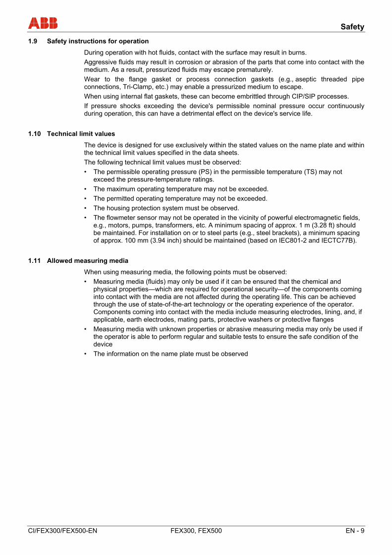
During operation with hot fluids, contact with the surface may result in burns.
Aggressive fluids may result in corrosion or abrasion of the parts that come into contact with the medium. As a result, pressurized fluids may escape prematurely.
Wear to the flange gasket or process connection gaskets (e.g., aseptic threaded pipe connections, Tri-Clamp, etc.) may enable a pressurized medium to escape.
When using internal flat gaskets, these can become embrittled through CIP/SIP processes.
If pressure shocks exceeding the device's permissible nominal pressure occur continuously during operation, this can have a detrimental effect on the device's service life.
1.10 Technical limit values
The device is designed for use exclusively within the stated values on the name plate and within the technical limit values specified in the data sheets.
The following technical limit values must be observed:
• The permissible operating pressure (PS) in the permissible temperature (TS) may not exceed the pressure-temperature ratings.
• The maximum operating temperature may not be exceeded.
• The permitted operating temperature may not be exceeded.
• The housing protection system must be observed.
• The flowmeter sensor may not be operated in the vicinity of powerful electromagnetic fields, e.g., motors, pumps, transformers, etc. A minimum spacing of approx. 1 m (3.28 ft) should be maintained. For installation on or to steel parts (e.g., steel brackets), a minimum spacing of approx. 100 mm (3.94 inch) should be maintained (based on IEC801-2 and IECTC77B).
1.11 Allowed measuring media
When using measuring media, the following points must be observed:
• Measuring media (fluids) may only be used if it can be ensured that the chemical and physical properties—which are required for operational security—of the components coming into contact with the media are not affected during the operating life. This can be achieved through the use of state-of-the-art technology or the operating experience of the operator. Components coming into contact with the media include measuring electrodes, lining, and, if applicable, earth electrodes, mating parts, protective washers or protective flanges
• Measuring media with unknown properties or abrasive measuring media may only be used if the operator is able to perform regular and suitable tests to ensure the safe condition of the device
• The information on the name plate must be observed
Safety
10 - EN FEX300, FEX500 CI/FEX300/FEX500-EN
1.12 Returning devices
Use the original packaging or suitably secure shipping containers if you need to return the device for repair or recalibration purposes. Fill out the return form (see the Appendix) and include this with the device.
According to EC guidelines for hazardous materials, the owner of hazardous waste is responsible for its disposal or must observe the following regulations for shipping purposes:
All devices delivered to ABB Automation Products GmbH must be free from any hazardous materials (acids, alkalis, solvents, etc.).
Rinse out and neutralize hazardous materials from all hollow spaces such as between meter tube and housing. For flowmeters larger than DN 400, the service screw (for draining condensate fluid) at the lower point of the housing must be opened to dispose of hazardous substances and to neutralize the coil and electrode chamber. These activities must be confirmed in writing using the return form.
Please
Please contact Customer Center Service acc. to page 1 for nearest service location.
1.13 Disposal
This product is manufactured from materials that can be reused by specialist recycling companies.
1.13.1 Information on WEEE Directive 2012/19/EU (Waste Electrical and Electronic Equipment)
This product is not subject to WEEE Directive 2012/19/EU or relevant national laws (e.g., ElektroG in Germany).
The product must be disposed of at a specialist recycling facility. Do not use municipal garbage collection points. According to the WEEE Directive 2012/19/EU, only products used in private applications may be disposed of at municipal garbage facilities. Proper disposal prevents negative effects on people and the environment, and supports the reuse of valuable raw materials.
If it is not possible to dispose of old equipment properly, ABB Service can accept and dispose of returns for a fee.
Device designs
CI/FEX300/FEX500-EN FEX300, FEX500 EN - 11
2 Device designs
IMPORTANT (NOTE)
An additional document with Ex safety instructions is available for measuring systems that are used in explosion hazardous areas. As a result, it is crucial that the specifications and data it lists are also observed.
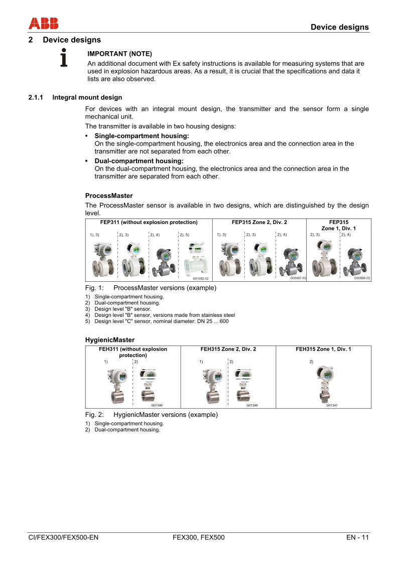
2.1.1 Integral mount design
For devices with an integral mount design, the transmitter and the sensor form a single mechanical unit.
The transmitter is available in two housing designs:
• Single-compartment housing: On the single-compartment housing, the electronics area and the connection area in the transmitter are not separated from each other.
• Dual-compartment housing: On the dual-compartment housing, the electronics area and the connection area in the transmitter are separated from each other.
ProcessMaster
The ProcessMaster sensor is available in two designs, which are distinguished by the design level.
FEP311 (without explosion protection) FEP315 Zone 2, Div. 2 FEP315 Zone 1, Div. 1
Fig. 1: ProcessMaster versions (example) 1) Single-compartment housing. 2) Dual-compartment housing. 3) Design level "B" sensor. 4) Design level "B" sensor, versions made from stainless steel 5) Design level "C" sensor, nominal diameter: DN 25 ... 600
HygienicMaster FEH311 (without explosion
protection) FEH315 Zone 2, Div. 2 FEH315 Zone 1, Div. 1
Fig. 2: HygienicMaster versions (example) 1) Single-compartment housing. 2) Dual-compartment housing.
G01082-02
1), 3) 2), 3) 2), 4) 2), 5)
G00487-02
1), 3) 2), 3) 2), 4)
G00886-02
2), 3) 2), 4)
G01346
1) 2)
G01346
1) 2)
G01347
2)
Device designs
12 - EN FEX300, FEX500 CI/FEX300/FEX500-EN
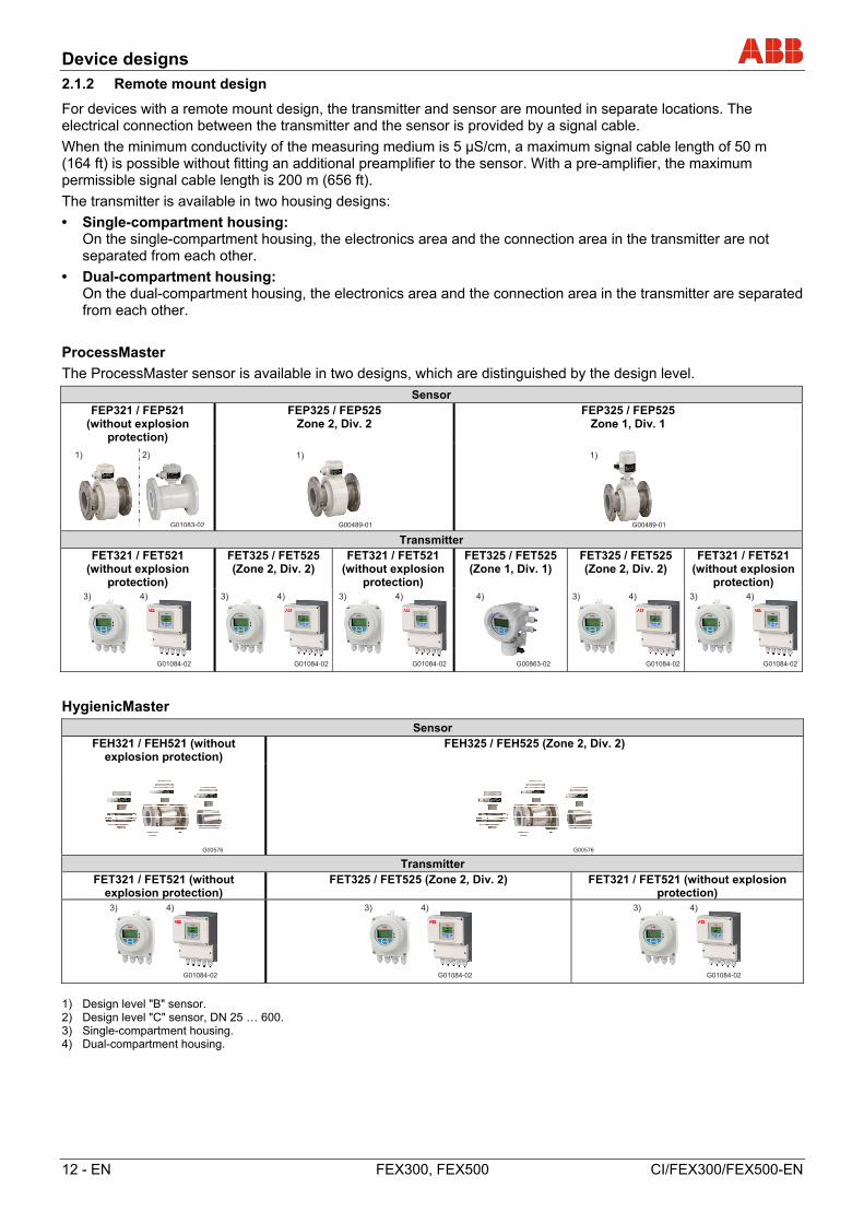
2.1.2 Remote mount design
For devices with a remote mount design, the transmitter and sensor are mounted in separate locations. The electrical connection between the transmitter and the sensor is provided by a signal cable.
When the minimum conductivity of the measuring medium is 5 µS/cm, a maximum signal cable length of 50 m (164 ft) is possible without fitting an additional preamplifier to the sensor. With a pre-amplifier, the maximum permissible signal cable length is 200 m (656 ft).
The transmitter is available in two housing designs:
• Single-compartment housing: On the single-compartment housing, the electronics area and the connection area in the transmitter are not separated from each other.
• Dual-compartment housing: On the dual-compartment housing, the electronics area and the connection area in the transmitter are separated from each other.
ProcessMaster
The ProcessMaster sensor is available in two designs, which are distinguished by the design level.
Sensor FEP321 / FEP521
(without explosion protection)
FEP325 / FEP525 Zone 2, Div. 2
FEP325 / FEP525 Zone 1, Div. 1
Transmitter
FET321 / FET521 (without explosion
protection)
FET325 / FET525 (Zone 2, Div. 2)
FET321 / FET521 (without explosion
protection)
FET325 / FET525 (Zone 1, Div. 1)
FET325 / FET525 (Zone 2, Div. 2)
FET321 / FET521 (without explosion
protection)
HygienicMaster
Sensor FEH321 / FEH521 (without
explosion protection) FEH325 / FEH525 (Zone 2, Div. 2)
Transmitter
FET321 / FET521 (without explosion protection)
FET325 / FET525 (Zone 2, Div. 2) FET321 / FET521 (without explosion protection)
1) Design level "B" sensor. 2) Design level "C" sensor, DN 25 … 600. 3) Single-compartment housing. 4) Dual-compartment housing.
G01083-02
1) 2)
G00489-01
1)
G00489-01
1)
G01084-02
3) 4)
G01084-02
3) 4)
G01084-02
3) 4)
G00863-02
4)
G01084-02
3) 4)
G01084-02
3) 4)
G01084-02
3) 4)
G01084-02
3) 4)
G01084-02
3) 4)
Transport
CI/FEX300/FEX500-EN FEX300, FEX500 EN - 13
3 Transport
3.1 Inspection
Check the devices for possible damage that may have occurred during transport. Damages in transit must be recorded on the transport documents. All claims for damages must be claimed without delay against the shipper and before the installation.
3.2 Transport of flanged units smaller than DN 450
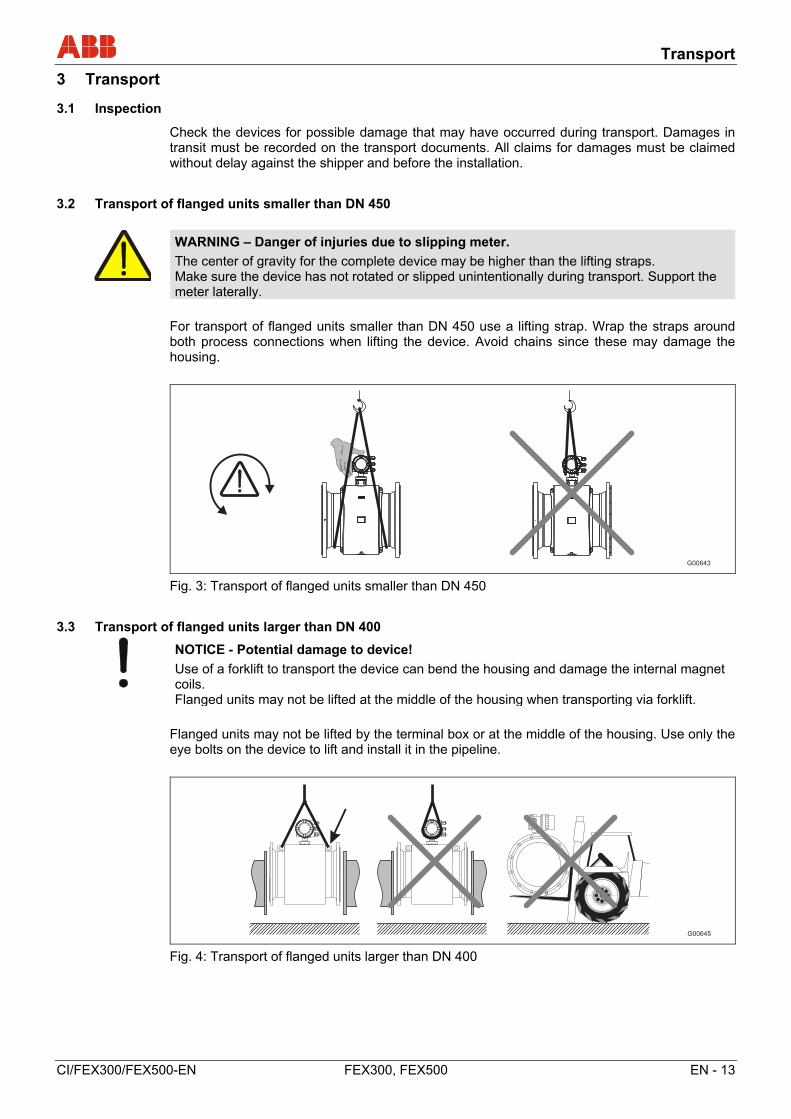
WARNING – Danger of injuries due to slipping meter.
The center of gravity for the complete device may be higher than the lifting straps. Make sure the device has not rotated or slipped unintentionally during transport. Support the meter laterally.
For transport of flanged units smaller than DN 450 use a lifting strap. Wrap the straps around both process connections when lifting the device. Avoid chains since these may damage the housing.
Fig. 3: Transport of flanged units smaller than DN 450
3.3 Transport of flanged units larger than DN 400
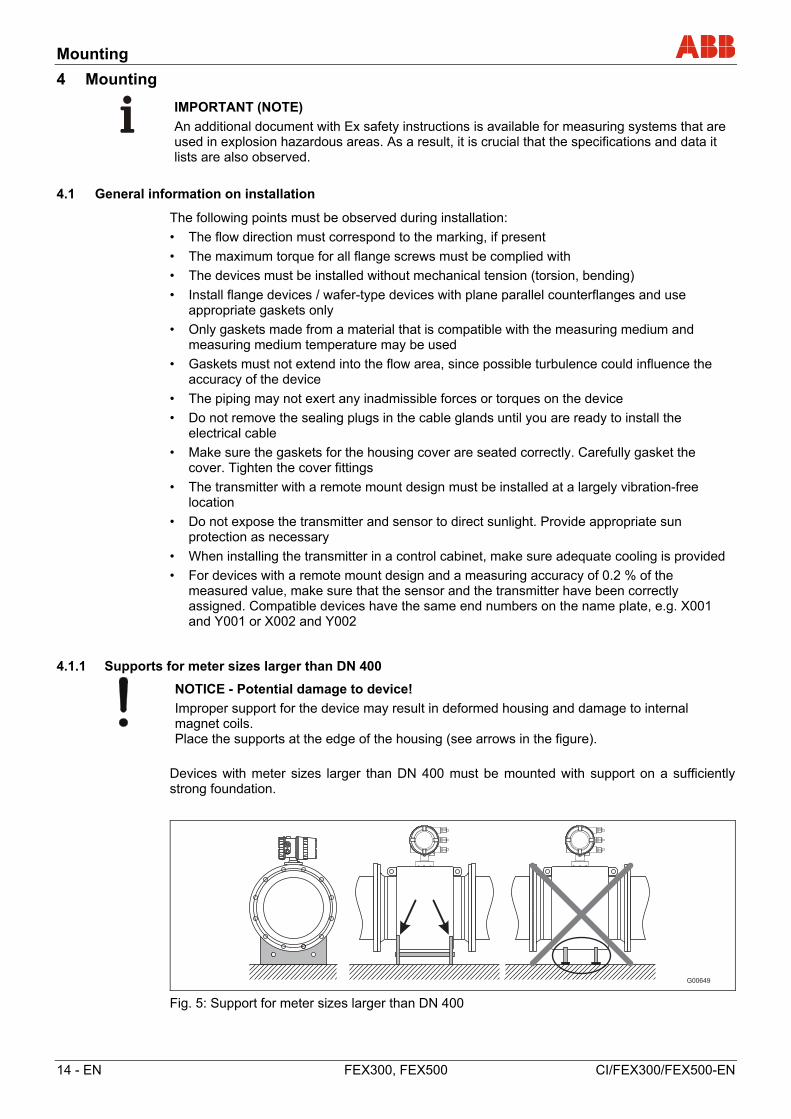
NOTICE - Potential damage to device!
Use of a forklift to transport the device can bend the housing and damage the internal magnet coils. Flanged units may not be lifted at the middle of the housing when transporting via forklift.
Flanged units may not be lifted by the terminal box or at the middle of the housing. Use only the eye bolts on the device to lift and install it in the pipeline.
Fig. 4: Transport of flanged units larger than DN 400
Mounting
14 - EN FEX300, FEX500 CI/FEX300/FEX500-EN
4 Mounting
IMPORTANT (NOTE)
An additional document with Ex safety instructions is available for measuring systems that are used in explosion hazardous areas. As a result, it is crucial that the specifications and data it lists are also observed.
4.1 General information on installation
The following points must be observed during installation:
• The flow direction must correspond to the marking, if present
• The maximum torque for all flange screws must be complied with
• The devices must be installed without mechanical tension (torsion, bending)
• Install flange devices / wafer-type devices with plane parallel counterflanges and use appropriate gaskets only
• Only gaskets made from a material that is compatible with the measuring medium and measuring medium temperature may be used
• Gaskets must not extend into the flow area, since possible turbulence could influence the accuracy of the device
• The piping may not exert any inadmissible forces or torques on the device
• Do not remove the sealing plugs in the cable glands until you are ready to install the electrical cable
• Make sure the gaskets for the housing cover are seated correctly. Carefully gasket the cover. Tighten the cover fittings
• The transmitter with a remote mount design must be installed at a largely vibration-free location
• Do not expose the transmitter and sensor to direct sunlight. Provide appropriate sun protection as necessary
• When installing the transmitter in a control cabinet, make sure adequate cooling is provided
• For devices with a remote mount design and a measuring accuracy of 0.2 % of the measured value, make sure that the sensor and the transmitter have been correctly assigned. Compatible devices have the same end numbers on the name plate, e.g. X001 and Y001 or X002 and Y002
4.1.1 Supports for meter sizes larger than DN 400
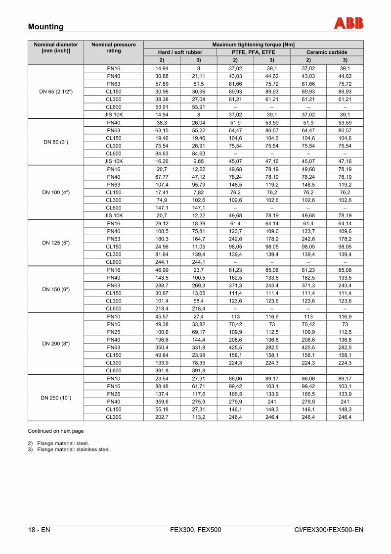
NOTICE - Potential damage to device!
Improper support for the device may result in deformed housing and damage to internal magnet coils. Place the supports at the edge of the housing (see arrows in the figure).
Devices with meter sizes larger than DN 400 must be mounted with support on a sufficiently strong foundation.
Fig. 5: Support for meter sizes larger than DN 400

Mounting
CI/FEX300/FEX500-EN FEX300, FEX500 EN - 15
4.1.2 Selecting gaskets
The following points must be observed when installing gaskets:
Devices with a hard rubber, soft rubber or ceramic carbide liner
• Devices with a hard / soft rubber liner always require additional gaskets
• ABB recommends using gaskets made from rubber or rubber-like sealing materials
• When selecting the gaskets, ensure that the tightening torques specified in chapter are not exceeded
Devices with a PTFE, PFA or ETFE liner
• In principle, devices with a PTFE, PFA or ETFE liner do not require additional gaskets
4.1.3 Devices with a wafer-type design
For devices with a wafer-type design, ABB offers an installation set as an accessory that comprises threaded rods, nuts, washers and centering sleeves for installation.
Fig. 6: Installation set for wafer-type installation
1 Threaded rod 2 Nut with washer
3 Centering sleeves
G013481 2 3 3

Mounting
16 - EN FEX300, FEX500 CI/FEX300/FEX500-EN
4.1.4 Installing the meter tube
Notice – potential damage to device!
The use of graphite with the flange or process connection gaskets is prohibited. This is because, in some instances, an electrically conductive coating may form on the inside of the meter tube. Vacuum shocks in the piping should be avoided to prevent damage to the liners (PTFE). Vacuum shocks can destroy the device.
The meter tube can be installed at any location in the piping while taking the installation conditions into account.
1. Remove protective plates, if present, to the right and left of the meter tube. To prevent possible leakage, make sure that the liner on the flange is not cut or damaged.
2. Position the meter tube coplanar and centered between the piping.
3. Install gaskets between the surfaces; see chapter .
IMPORTANT (NOTE)
For achieve the best results, ensure the gaskets fit concentrically with the meter tube
4. Use the appropriate screws for the holes in accordance with chapter .
5. Slightly grease the threaded nuts.
6. Tighten the nuts in a crosswise manner as shown in the figure. Observe the tightening torques in accordance with chapter ! First tighten the nuts to approx. 50 % of the maximum torque, then to 80 %, and finally a third time to the maximum torque. Do not exceed the max. torque.
G00034
1
2
7
8
5
3
4
6
1
2
3
4
Fig. 7

Mounting
CI/FEX300/FEX500-EN FEX300, FEX500 EN - 17
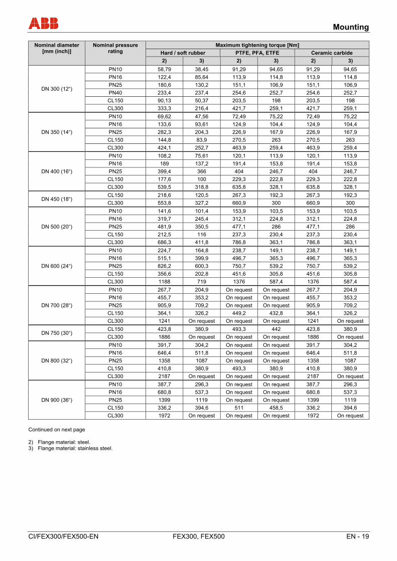
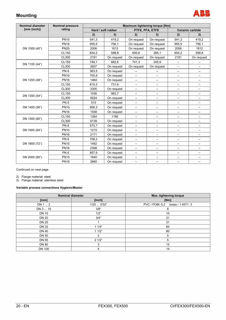
4.2 Torque information
IMPORTANT (NOTE) The specified torques are valid only for greased threads and piping that is not subject to tensile stress.
ProcessMaster in flange design and HygienicMaster in flange or wafer-type design
Nominal diameter [mm (inch)]
Nominal pressure rating
Maximum tightening torque [Nm]
Hard / soft rubber PTFE, PFA, ETFE Ceramic carbide
2) 3) 2) 3) 2) 3)
DN 3 ... 101) (1/10 ... 3/8“1))
PN40 – – 12,43 12,43 – –
PN63/100 – – 12,43 12,43 – –
CL150 – – 12,98 12,98 – –
CL300 – – 4,94 17,38 – –
JIS 10K – – 12,43 12,43 – –
DN 15 (1/2“)
PN40 6,74 4,29 14,68 14,68 – –
PN63/100 13,19 11,2 22,75 22,75 – –
CL150 3,65 3,65 12,98 12,98 – –
CL300 4,94 3,86 4,94 17,38 – –
CL600 9,73 9,73 – – – –
JIS 10K 2,84 1,37 14,68 14,68 – –
DN 20 (3/4“)
PN40 9,78 7,27 20,75 20,75 – –
PN63/100 24,57 20,42 42,15 42,15 – –
CL150 5,29 5,29 18,49 18,49 – –
CL300 9,77 9,77 33,28 33,28 – –
CL600 15,99 15,99 – – – –
JIS 10K 4,1 1,88 20,75 20,75 – –
DN 25 (1“)
PN40 13,32 8,6 13,32 8,6 13,32 8,6
PN63/100 32,09 31,42 53,85 53,85 53,85 53,85
CL150 5,04 2,84 23,98 23,98 23,98 23,98
CL300 17,31 16,42 65,98 38,91 65,98 38,91
CL600 22,11 22,11 – – – –
JIS 10K 8,46 5,56 26,94 26,94 26,94 26,94
DN 32 (1 1/4“)
PN40 27,5 15,01 45,08 45,08 45,08 45,08
PN63/100 42,85 41,45 74,19 70,07 74,19 70,07
CL150 4,59 1,98 29,44 29,44 29,44 29,44
CL300 25,61 14,22 45,52 45,52 45,52 45,52
CL600 34,09 34,09 – – – –
JIS 10K 9,62 4,9 45,08 45,08 45,08 45,08
DN 40 (1 1/2“)
PN40 30,44 23,71 56,06 56,06 56,06 56,06
PN63/100 62,04 51,45 97,08 97,08 97,08 97,08
CL150 5,82 2,88 36,12 36,12 36,12 36,12
CL300 33,3 18,41 73,99 73,99 73,99 73,99
CL600 23,08 23,08 – – – –
JIS 10K 12,49 6,85 56,06 56,06 56,06 56,06
DN 50 (1 1/2“)
PN40 41,26 27,24 71,45 71,45 71,45 71,45
PN63 71,62 60,09 109,9 112,6 109,9 112,6
CL150 22,33 22,33 66,22 66,22 66,22 66,22
CL300 17,4 22,33 38,46 38,46 38,46 38,46
CL600 35,03 35,03 – – – –
JIS 10K 17,27 10,47 71,45 71,45 71,45 71,45
Continued on next page 1) Connection flange DIN / EN1092-1 = DN 10 (3/8"), connection flange ASME = DN 15 (1/2"). 2) Flange material: steel. 3) Flange material: stainless steel.
Mounting
18 - EN FEX300, FEX500 CI/FEX300/FEX500-EN
Nominal diameter [mm (inch)]
Nominal pressure rating
Maximum tightening torque [Nm]
Hard / soft rubber PTFE, PFA, ETFE Ceramic carbide
2) 3) 2) 3) 2) 3)
DN 65 (2 1/2“)
PN16 14,94 8 37,02 39,1 37,02 39,1
PN40 30,88 21,11 43,03 44,62 43,03 44,62
PN63 57,89 51,5 81,66 75,72 81,66 75,72
CL150 30,96 30,96 89,93 89,93 89,93 89,93
CL300 38,38 27,04 61,21 61,21 61,21 61,21
CL600 53,91 53,91 – – – –
JIS 10K 14,94 8 37,02 39,1 37,02 39,1
DN 80 (3“)
PN40 38,3 26,04 51,9 53,59 51,9 53,59
PN63 63,15 55,22 64,47 80,57 64,47 80,57
CL150 19,46 19,46 104,6 104,6 104,6 104,6
CL300 75,54 26,91 75,54 75,54 75,54 75,54
CL600 84,63 84,63 – – – –
JIS 10K 16,26 9,65 45,07 47,16 45,07 47,16
DN 100 (4“)
PN16 20,7 12,22 49,68 78,19 49,68 78,19
PN40 67,77 47,12 78,24 78,19 78,24 78,19
PN63 107,4 95,79 148,5 119,2 148,5 119,2
CL150 17,41 7,82 76,2 76,2 76,2 76,2
CL300 74,9 102,6 102,6 102,6 102,6 102,6
CL600 147,1 147,1 – – – –
JIS 10K 20,7 12,22 49,68 78,19 49,68 78,19
DN 125 (5“)
PN16 29,12 18,39 61,4 64,14 61,4 64,14
PN40 108,5 75,81 123,7 109,6 123,7 109,6
PN63 180,3 164,7 242,6 178,2 242,6 178,2
CL150 24,96 11,05 98,05 98,05 98,05 98,05
CL300 81,64 139,4 139,4 139,4 139,4 139,4
CL600 244,1 244,1 – – – –
DN 150 (6“)
PN16 46,99 23,7 81,23 85,08 81,23 85,08
PN40 143,5 100,5 162,5 133,5 162,5 133,5
PN63 288,7 269,3 371,3 243,4 371,3 243,4
CL150 30,67 13,65 111,4 111,4 111,4 111,4
CL300 101,4 58,4 123,6 123,6 123,6 123,6
CL600 218,4 218,4 – – – –
DN 200 (8“)
PN10 45,57 27,4 113 116,9 113 116,9
PN16 49,38 33,82 70,42 73 70,42 73
PN25 100,6 69,17 109,9 112,5 109,9 112,5
PN40 196,6 144,4 208,6 136,8 208,6 136,8
PN63 350,4 331,8 425,5 282,5 425,5 282,5
CL150 49,84 23,98 158,1 158,1 158,1 158,1
CL300 133,9 78,35 224,3 224,3 224,3 224,3
CL600 391,8 391,8 – – – –
DN 250 (10“)
PN10 23,54 27,31 86,06 89,17 86,06 89,17
PN16 88,48 61,71 99,42 103,1 99,42 103,1
PN25 137,4 117,6 166,5 133,9 166,5 133,9
PN40 359,6 275,9 279,9 241 279,9 241
CL150 55,18 27,31 146,1 148,3 146,1 148,3
CL300 202,7 113,2 246,4 246,4 246,4 246,4
Continued on next page 2) Flange material: steel. 3) Flange material: stainless steel.
Mounting
CI/FEX300/FEX500-EN FEX300, FEX500 EN - 19
Nominal diameter [mm (inch)]
Nominal pressure rating
Maximum tightening torque [Nm]
Hard / soft rubber PTFE, PFA, ETFE Ceramic carbide
2) 3) 2) 3) 2) 3)
DN 300 (12“)
PN10 58,79 38,45 91,29 94,65 91,29 94,65
PN16 122,4 85,64 113,9 114,8 113,9 114,8
PN25 180,6 130,2 151,1 106,9 151,1 106,9
PN40 233,4 237,4 254,6 252,7 254,6 252,7
CL150 90,13 50,37 203,5 198 203,5 198
CL300 333,3 216,4 421,7 259,1 421,7 259,1
DN 350 (14“)
PN10 69,62 47,56 72,49 75,22 72,49 75,22
PN16 133,6 93,61 124,9 104,4 124,9 104,4
PN25 282,3 204,3 226,9 167,9 226,9 167,9
CL150 144,8 83,9 270,5 263 270,5 263
CL300 424,1 252,7 463,9 259,4 463,9 259,4
DN 400 (16“)
PN10 108,2 75,61 120,1 113,9 120,1 113,9
PN16 189 137,2 191,4 153,8 191,4 153,8
PN25 399,4 366 404 246,7 404 246,7
CL150 177,6 100 229,3 222,8 229,3 222,8
CL300 539,5 318,8 635,8 328,1 635,8 328,1
DN 450 (18“) CL150 218,6 120,5 267,3 192,3 267,3 192,3
CL300 553,8 327,2 660,9 300 660,9 300
DN 500 (20“)
PN10 141,6 101,4 153,9 103,5 153,9 103,5
PN16 319,7 245,4 312,1 224,8 312,1 224,8
PN25 481,9 350,5 477,1 286 477,1 286
CL150 212,5 116 237,3 230,4 237,3 230,4
CL300 686,3 411,8 786,8 363,1 786,8 363,1
DN 600 (24“)
PN10 224,7 164,8 238,7 149,1 238,7 149,1
PN16 515,1 399,9 496,7 365,3 496,7 365,3
PN25 826,2 600,3 750,7 539,2 750,7 539,2
CL150 356,6 202,8 451,6 305,8 451,6 305,8
CL300 1188 719 1376 587,4 1376 587,4
DN 700 (28“)
PN10 267,7 204,9 On request On request 267,7 204,9
PN16 455,7 353,2 On request On request 455,7 353,2
PN25 905,9 709,2 On request On request 905,9 709,2
CL150 364,1 326,2 449,2 432,8 364,1 326,2
CL300 1241 On request On request On request 1241 On request
DN 750 (30“) CL150 423,8 380,9 493,3 442 423,8 380,9
CL300 1886 On request On request On request 1886 On request
DN 800 (32“)
PN10 391,7 304,2 On request On request 391,7 304,2
PN16 646,4 511,8 On request On request 646,4 511,8
PN25 1358 1087 On request On request 1358 1087
CL150 410,8 380,9 493,3 380,9 410,8 380,9
CL300 2187 On request On request On request 2187 On request
DN 900 (36“)
PN10 387,7 296,3 On request On request 387,7 296,3
PN16 680,8 537,3 On request On request 680,8 537,3
PN25 1399 1119 On request On request 1399 1119
CL150 336,2 394,6 511 458,5 336,2 394,6
CL300 1972 On request On request On request 1972 On request
Continued on next page 2) Flange material: steel. 3) Flange material: stainless steel.
Mounting
20 - EN FEX300, FEX500 CI/FEX300/FEX500-EN
Nominal diameter [mm (inch)]
Nominal pressure rating
Maximum tightening torque [Nm]
Hard / soft rubber PTFE, PFA, ETFE Ceramic carbide
2) 3) 2) 3) 2) 3)
DN 1000 (40“)
PN10 541,3 419,2 On request On request 541,3 419,2
PN16 955,5 756,1 On request On request 955,5 756,1
PN25 2006 1612 On request On request 2006 1612
CL150 654,2 598,8 650,6 385,1 654,2 598,8
CL300 2181 On request On request On request 2181 On request
DN 1100 (44“) CL150 749,1 682,6 741,3 345,9 – –
CL300 2607 On request On request On request – –
DN 1200 (48“)
PN 6 363,5 On request – – – –
PN10 705,9 On request – – – –
PN16 1464 On request – – – –
CL150 815,3 731,6 – – – –
CL300 3300 On request – – – –
DN 1350 (54“) CL150 1036 983,7 – – – –
CL300 5624 On request – – – –
DN 1400 (56“)
PN 6 515 On request – – – –
PN10 956,3 On request – – – –
PN16 1558 On request – – – –
DN 1500 (60“) CL150 1284 1166 – – – –
CL300 6139 On request – – – –
DN 1600 (64“)
PN 6 570,7 On request – – – –
PN10 1215 On request – – – –
PN16 2171 On request – – – –
DN 1800 (72“)
PN 6 708,2 On request – – – –
PN10 1492 On request – – – –
PN16 2398 On request – – – –
DN 2000 (80“)
PN 6 857,9 On request – – – –
PN10 1840 On request – – – –
PN16 2860 On request – – – –
Continued on next page 2) Flange material: steel. 3) Flange material: stainless steel. Variable process connections HygienicMaster
Nominal diameter Max. tightening torque
[mm] [inch] [Nm]
DN 1 ... 2 1/25 ... 3/32“ PVC / POM: 0.2 brass / 1.4571: 3
DN 3 ... 10 3/8“ 8
DN 15 1/2“ 10
DN 20 3/4“ 21
DN 25 1 31
DN 32 1 1/4“ 60
DN 40 1 1/2“ 80
DN 50 2 5
DN 65 2 1/2“ 5
DN 80 3 15
DN 100 4 14
Mounting
CI/FEX300/FEX500-EN FEX300, FEX500 EN - 21
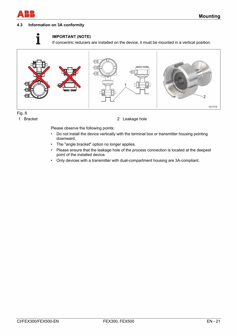
4.3 Information on 3A conformity
IMPORTANT (NOTE)
If concentric reducers are installed on the device, it must be mounted in a vertical position.
G01319
1
2
Fig. 8
1 Bracket 2 Leakage hole Please observe the following points:
• Do not install the device vertically with the terminal box or transmitter housing pointing downward.
• The "angle bracket" option no longer applies.
• Please ensure that the leakage hole of the process connection is located at the deepest point of the installed device.
• Only devices with a transmitter with dual-compartment housing are 3A-compliant.

Mounting
22 - EN FEX300, FEX500 CI/FEX300/FEX500-EN
Change from one to two columns
4.4 Installation Requirements
4.4.1 Flow direction
The device measures the flowrate in both directions. Forward flow is the factory setting, as shown in Fig. 9.
G00657-01 Fig. 9
4.4.2 Electrode axis
Electrode axis (1) should be horizontal if at all possible or no more that 45° from horizontal.
G00041
max. 45°
1
Fig. 10
4.4.3 In- and outlet pipe sections
The metering principle is independent of the flow profile as long as standing eddies do not extend into the metering section, such as may occur after double elbows (1), in the event of tangential inflow, or where half-open gate valves are located upstream of the flowmeter sensor. In such cases, measures must be put in place to normalize the flow profile. • Do not install fittings, manifolds, valves, etc., directly in front of the
flowmeter sensor (1). • Butterfly valves must be installed so that the valve plate does not
extend into the flowmeter sensor. • Valves or other turn-off components should be installed in the
outlet pipe section (2). Experience has shown that, in most installations, straight inlet sections 3 x DN long and straight outlet sections 2 x DN long are sufficient (DN = nominal diameter of the sensor Fig. 11 ). For test stands, the reference conditions of 10 x DN straight inlet and 5 x DN straight outlet must be provided, in accordance with EN 29104 / ISO 9104.
G00983
1 2
2xDN3xDN Fig. 11
4.4.4 Vertical connections
Vertical installation for measuring abrasive fluids, preferably with flow in upward direction.
G00039-01 Fig. 12
4.4.5 Horizontal connections
• Meter tube must always be completely full. • Provide for a slight incline of the connection for degassing.
G00038
3°
Fig. 13
4.4.6 Free inlet or outlet
• Do not install the flowmeter at the highest point or in the draining- off side of the pipeline, flowmeter runs empty, air bubbles can form (1).
• Provide for a siphon fluid intake for free inlets or outlets so that the pipeline is always full (2).
G00040
1
2
Fig. 14
4.4.7 Strongly contaminated measuring media
For strongly contaminated measuring media, a bypass connection according to the figure is recommended so that operation of the system can continue to run without interruption the during the mechanical cleaning.
G00042 Fig. 15
Mounting
CI/FEX300/FEX500-EN FEX300, FEX500 EN - 23
4.4.8 Installation in the vicinity of pumps
For flowmeter primaries which are to be installed in the vicinity of pumps or other vibration generating equipment, the utilization of mechanical snubbers is advantageous.
G00561 Fig. 16
4.4.9 Installation of the high temperature design
The high temperature design allows for complete thermal insulation of the sensor. The pipeline and sensor must be insulated after installing the unit according to the following illustration.
G00654
1
Fig. 17
1 Insulation
4.4.10 Devices with extended diagnostic functions
For devices with extended diagnostic functions different installation conditions may be valid. For further information read and observe chapter General remarks.
4.4.11 Minimum distance
In order to prevent the devices from interfering with each other, a minimum distance of 0.7 m (2.3 ft) must be maintained between the devices.
Fig. 18
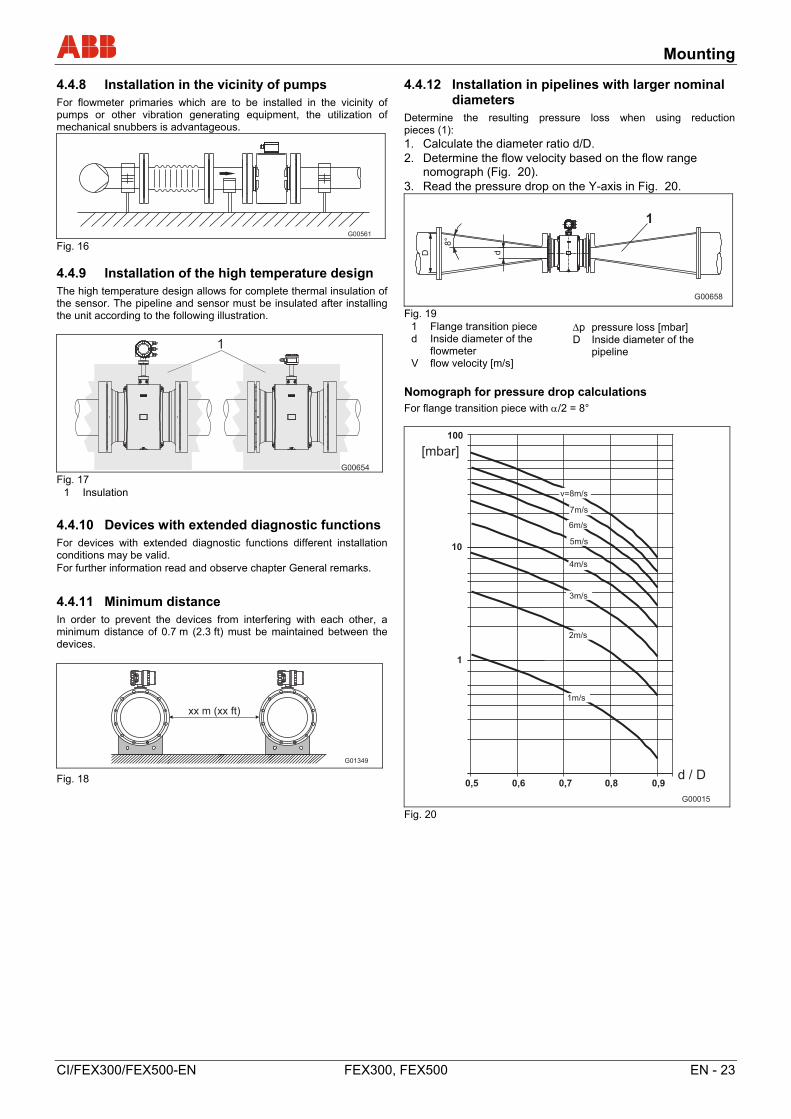
4.4.12 Installation in pipelines with larger nominal diameters
Determine the resulting pressure loss when using reduction pieces (1): 1. Calculate the diameter ratio d/D. 2. Determine the flow velocity based on the flow range
nomograph (Fig. 20). 3. Read the pressure drop on the Y-axis in Fig. 20.
Fig. 19
1 Flange transition piece d Inside diameter of the
flowmeter V flow velocity [m/s]
p pressure loss [mbar] D Inside diameter of the
pipeline
Nomograph for pressure drop calculations For flange transition piece with /2 = 8°
Fig. 20
Change from one to two columns
G01349
xx m (xx ft)
Mounting
24 - EN FEX300, FEX500 CI/FEX300/FEX500-EN
4.5 Ground
4.5.1 General information on ground connections
Observe the following items when grounding the device:
• For plastic pipes or pipes with insulating lining, the ground is provided by the grounding plate or grounding electrodes.
• When stray potentials are present, install a grounding plate upstream and downstream of the flowmeter sensor.
• For measurement-related reasons, the potentials in the station ground and in the pipeline should be identical.
• An additional ground on the terminals is not required.
IMPORTANT (NOTE)
If the flowmeter sensor is installed in plastic or earthenware pipelines, or in pipelines with an insulating lining, transient current may flow through the grounding electrode in special cases. In the long term, this may destroy the sensor, since the ground electrode will in turn degrade electrochemically. In these special cases, the connection to the ground must be performed using grounding plates. Install a grounding plate upstream and downstream of the device in this case.
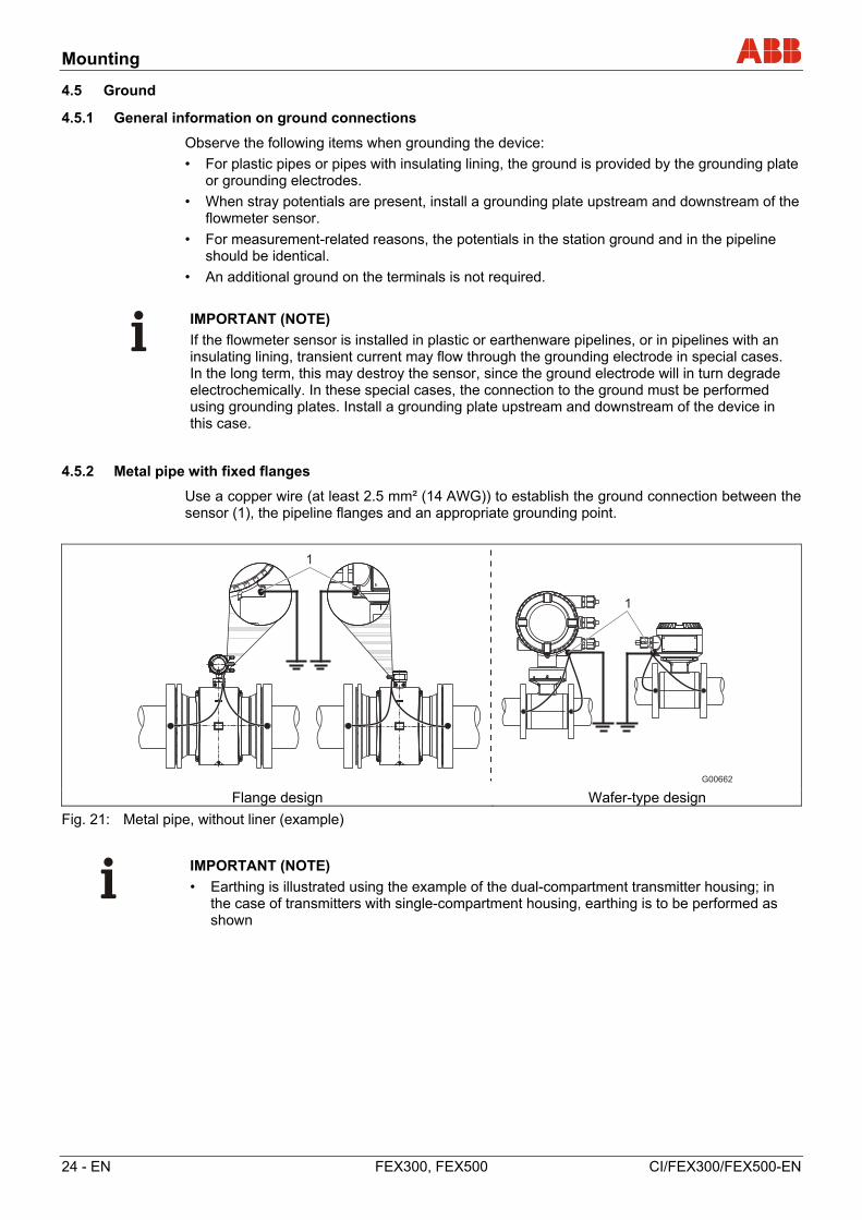
4.5.2 Metal pipe with fixed flanges
Use a copper wire (at least 2.5 mm² (14 AWG)) to establish the ground connection between the sensor (1), the pipeline flanges and an appropriate grounding point.
Flange design Wafer-type design
Fig. 21: Metal pipe, without liner (example)
IMPORTANT (NOTE)
• Earthing is illustrated using the example of the dual-compartment transmitter housing; in the case of transmitters with single-compartment housing, earthing is to be performed as shown
Mounting
CI/FEX300/FEX500-EN FEX300, FEX500 EN - 25
4.5.3 Metal pipe with loose flanges
1. Solder the threaded nuts M6 (1) to the pipeline and connect the ground as shown in the illustration.
2. Use a copper wire (at least 2.5 mm² (14 AWG)) to establish the ground connection between the sensor (2) and an appropriate grounding point.
Flange design Wafer-type design
Fig. 22: Metal pipe, without liner (example)
IMPORTANT (NOTE)
• Earthing is illustrated using the example of the dual-compartment transmitter housing; in the case of transmitters with single-compartment housing, earthing is to be performed as shown
Mounting
26 - EN FEX300, FEX500 CI/FEX300/FEX500-EN
4.5.4 Plastic pipes, non-metallic pipes or pipes with insulating liner
For plastic pipes or pipes with insulating lining, the earthing for the measuring medium is provided by the grounding plate as shown in the figure below or via grounding electrodes that must be installed in the device (option). If grounding electrodes are used, the grounding plate is not necessary.
1. Install the flowmeter sensor with grounding plate (3) in the pipeline.
2. Connect the terminal lug (2) for the grounding plate (3) and ground connection (1) on the flowmeter sensor with the grounding strap.
3. Use a copper wire (min. 2.5 mm² (14 AWG)) to link the earthing terminal (1) to a suitable earthing point.
Flange design Wafer-type design
Fig. 23: Plastic pipes, non-metallic pipes or pipes with insulating liner
IMPORTANT (NOTE)
• Earthing is illustrated using the example of the dual-compartment transmitter housing; in the case of transmitters with single-compartment housing, earthing is to be performed as shown
Mounting
CI/FEX300/FEX500-EN FEX300, FEX500 EN - 27
4.5.5 Sensor type HygienicMaster
Ground the stainless steel model as shown in the figure. The measuring fluid is grounded via the adapter (1) and an additional ground is not required.
Fig. 24
4.5.6 Ground for devices with protective plates
The protective plates are used to protect the edges of the liner in the measuring tube, e.g., for abrasive fluids. In addition, they function as a grounding plate.
• For plastic or pipes with insulating lining, electrically connect the protective plate in the same manner as a grounding plate.
4.5.7 Ground with conductive PTFE grounding plate
For devices with a meter size between DN 10 … 250, grounding plates made of conductive PTFE are available. These are installed in a similar way to conventional grounding plates.
Electrical connections
28 - EN FEX300, FEX500 CI/FEX300/FEX500-EN
5 Electrical connections
5.1 Routing the signal and magnet coil cable
Observe the following points when routing cables:
• A magnet coil cable (red and brown) is run parallel to the signal lines (violet and blue). As a result, only one cable is required between the flowmeter sensor and the transmitter. Do not run the cable over junction boxes or terminal strips.
• The signal cable carries a voltage signal of only a few millivolts and must, therefore, be routed over the shortest possible distance. The max. allowable signal cable length is 50 m (164 ft) without pre-amplifier and 200 m (656 ft) with pre-amplifier.
• Avoid routing the cable in the vicinity of electrical equipment or switching elements that can create stray fields, switching pulses, and induction. If this is not possible, run the signal / magnet coil cable through a metal pipe and connect this to the station ground.
• All leads must be shielded and connected to the station ground potential.
• To shield against magnetic interspersion, the cable contains outer shielding. This is attached to the SE clamp.
• The supplied stranded steel wire is also connected to the SE clamp
• Do not damage the sheathing of the cable during installation.
• Make sure during installation that the cable is provided with a water trap (1). For vertical installation, align the cable glands pointing downward.
Fig. 25
Electrical connections
CI/FEX300/FEX500-EN FEX300, FEX500 EN - 29
5.2 Preparing the signal and magnet coil cable in the case of transmitters with dual-compartment housing
5.2.1 Cable with part number D173D027U01
Prepare both cable ends as shown.
IMPORTANT (NOTE)
Use wire end sleeves.
• Wire end sleeves 0.75 mm2 (AWG 19), for shielding (1S, 2S)
• Wire end sleeves 0.5 mm2 (AWG 20), for all other wires
The shields may not touch (signal short circuit).
Fig. 26: Flowmeter sensor side, dimensions in mm (inch)
G00667
X
L1
15 ( )0.59L2
123456789
10 11
8 ( )0.31
25 ( )0.98
"X"
Fig. 27: Transmitter side, dimensions in mm (inch)
L1 maximum stripped length = 105 (4.10)
1 Measurement potential 3, green L2 = 70 (2.76) 2 Signal line E1, violet L2 = 60 (2.36) 3 Shield 1S L2 = 60 (2.36) 4 Shield 2S L2 = 60 (2.36) 5 Signal line, E2, blue L2 = 60 (2.36) 6 Data line, D2, yellow L2 = 70 (2.76)
7 Data line, D1, orange L2 = 70 (2.76) 8 Magnet coil, M2, red L2 = 90 (3.54) 9 Magnet coil, M1, brown L2 = 90 (3.54) 10Ground wire, steel 11SE clamp
Electrical connections
30 - EN FEX300, FEX500 CI/FEX300/FEX500-EN
5.2.2 Cable with part number D173D031U01
Prepare both cable ends as shown.
IMPORTANT (NOTE)
Use wire end sleeves.
• Wire end sleeves 0.75 mm2 (AWG 19), for shielding (1S, 2S)
• Wire end sleeves 0.5 mm2 (AWG 20), for all other wires
The shields may not touch (signal short circuit).
Flowmeter sensor side
G01030-01X
L2
123456789
10 11 12 13
8 (0.31)
25 (0.98)
"X"
70 (2.76)
123456789
13 12 11 10
X
8 (0.31)
25 (0.98)
"X"
Transmitter side
Fig. 28: Flowmeter sensor side, dimensions in mm (inch)
1 Measurement potential 3, green L2 = 70 (2.76) 2 Signal line E1, violet L2 = 60 (2.36) 3 Shield 1S L2 = 60 (2.36) 4 Shield 2S L2 = 60 (2.36) 5 Signal line, E2, blue L2 = 60 (2.36) 6 Data line, D2, yellow L2 = 70 (2.76) 7 Data line, D1, orange L2 = 70 (2.76)
8 Magnet coil, M2, red L2 = 90 (3.54) 9 Magnet coil, M1, brown L2 = 90 (3.54) 10Foil shield (D1, D2) 11Foil shield continuity wire (D1, D2) 12Ground wire, steel 13SE clamp
Electrical connections
CI/FEX300/FEX500-EN FEX300, FEX500 EN - 31
5.3 Preparing the signal and magnet coil cable in the case of transmitters with single-compartment housing
G01323
M1 M2 D1 D2 SE 3 2S E2 E1 1S
M1 M2 D1 D2 SE 3 2S E2 E1 1S
D173D031U01
D173D027U01
1
2
4
5
6
1
Fig. 29: Transmitter side, dimensions in mm (inch)
1 Ground wire 2 Wire mesh shield (D173D027U01 only) 4 Twisted wire mesh shield (D173D027U01 only)
5 Foil shield continuity wire D1, D2 (D173D031U01 only)
6 Foil shield D1, D2 (D173D031U01 only)
Terminal Description, wire color Length in mm (inch)
M1 Magnet coil, brown 70 (2.76) M2 Magnet coil, red 70 (2.76) D1 Data line, orange 70 (2.76) D2 Data line, yellow 70 (2.76) SE Shield - 3 Measurement potential, green 70 (2.76) 2S Shield for E2 60 (2.36) E2 Signal line, blue 60 (2.36) E1 Signal line, violet 60 (2.36) 1S Shield for E1 60 (2.36)

Electrical connections
32 - EN FEX300, FEX500 CI/FEX300/FEX500-EN
IMPORTANT (NOTE)
• Use wire end sleeves.
- Wire end sleeves 0.75 mm2 (AWG 19), for shielding (1S, 2S)
- Wire end sleeves 0.5 mm2 (AWG 20), for all other wires
• The shields may not touch (signal short circuit). en
Prepare the cable end on the transmitter side as shown in Fig. 29.
5.3.1 Cable with part number D173D027U01
• Twist the wire mesh shield of the cable and connect to the ground terminal.
• Connect the ground wire of the cable to the SE clamp of the terminal strip.
• Connect all other wires as shown in Fig. 29.
5.3.2 Cable with part number D173D031U01
• Connect the cable ground wire together with the foil shield continuity wire from D1, D2 to the SE clamp of the terminal strip.
• When using the flowmeter sensor in systems with cathodic corrosion protection (CCP), connect the cable ground wire together with the foil shield continuity wire from D1, D2 to the SE clamp of the terminal strip.
• Connect all other wires as shown in Fig. 29.
5.4 Connecting the transmitter
IMPORTANT (NOTE)
An additional document with Ex safety instructions is available for measuring systems that are used in explosion hazardous areas. As a result, it is crucial that the specifications and data it lists are also observed.
5.4.1 Connecting the power supply
The line voltage and power consumption are indicated on the name plate for the transmitter.
A circuit breaker with a maximum rated current of 16 A must be installed in the supply power line of the transmitter.
The wire cross-sectional area of the supply power cable and the circuit breaker used must comply with VDE 0100 and must be dimensioned in accordance with the current consumption of the flowmeter measuring system. The leads must comply with IEC 227 and/or IEC 245.
The circuit breaker should be located near the transmitter and marked as being associated with the device.
The supply power is connected to terminal L (phase), N (neutral), or 1+, 2-, and PE, as stated on the name plate.
Connect the transmitter and flowmeter sensor to functional ground.
Important (Note)
• Observe the limit values for the supply power provided in the data sheet and operating instructions.
• Observe the voltage drop for large cable lengths and small cable cross-sections. The voltage at the terminals of the device may not fall below the minimum value required.
• Complete the electrical connection according to the connection diagram.
Electrical connections
CI/FEX300/FEX500-EN FEX300, FEX500 EN - 33
5.4.2 Transmitter with dual-compartment housing
The terminals for the supply power can be found under the terminal cover (1).
G00678
1
Fig. 30
1 Terminal cover
5.4.3 Transmitter with single-compartment housing
G01320
1
Fig. 31
1 Terminals (power supply)
Electrical connections
34 - EN FEX300, FEX500 CI/FEX300/FEX500-EN
5.4.4 Connecting the signal and magnet coil cables
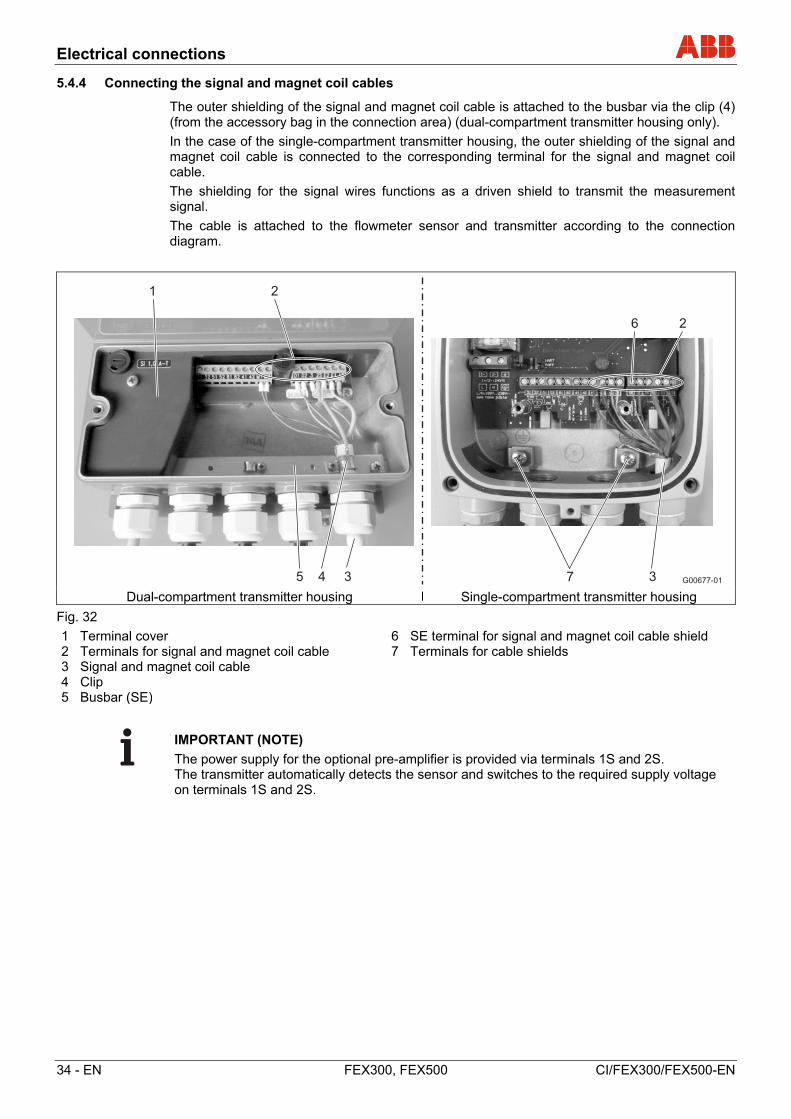
The outer shielding of the signal and magnet coil cable is attached to the busbar via the clip (4) (from the accessory bag in the connection area) (dual-compartment transmitter housing only).
In the case of the single-compartment transmitter housing, the outer shielding of the signal and magnet coil cable is connected to the corresponding terminal for the signal and magnet coil cable.
The shielding for the signal wires functions as a driven shield to transmit the measurement signal.
The cable is attached to the flowmeter sensor and transmitter according to the connection diagram.
G00677-01
1 2
5 4 3 3
6 2
7 Dual-compartment transmitter housing Single-compartment transmitter housing
Fig. 32
1 Terminal cover 2 Terminals for signal and magnet coil cable 3 Signal and magnet coil cable 4 Clip 5 Busbar (SE)
6 SE terminal for signal and magnet coil cable shield 7 Terminals for cable shields
IMPORTANT (NOTE)
The power supply for the optional pre-amplifier is provided via terminals 1S and 2S. The transmitter automatically detects the sensor and switches to the required supply voltage on terminals 1S and 2S.
Electrical connections
CI/FEX300/FEX500-EN FEX300, FEX500 EN - 35
5.5 Connecting the flowmeter sensor
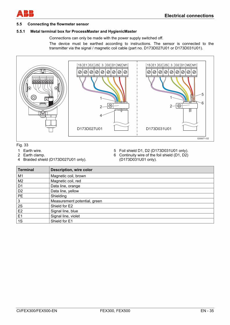
5.5.1 Metal terminal box for ProcessMaster and HygienicMaster
Connections can only be made with the power supply switched off.
The device must be earthed according to instructions. The sensor is connected to the transmitter via the signal / magnetic coil cable (part no. D173D027U01 or D173D031U01).
G00671-02
1S E1 E2 2S 3 D2 D1 M2 M1
1S E1 E2 2S 3 D2 D1 M2 M1 1S E1 E2 2S 3 D2 D1 M2 M1
D173D027U01 D173D031U01
1
2
4
1
2
5
6
Fig. 33
1 Earth wire. 2 Earth clamp. 4 Braided shield (D173D027U01 only).
5 Foil shield D1, D2 (D173D031U01 only). 6 Continuity wire of the foil shield (D1, D2)
(D173D031U01 only).
Terminal Description, wire color
M1 Magnetic coil, brown M2 Magnetic coil, red D1 Data line, orange D2 Data line, yellow PE Shielding 3 Measurement potential, green 2S Shield for E2 E2 Signal line, blue E1 Signal line, violet 1S Shield for E1
Electrical connections
36 - EN FEX300, FEX500 CI/FEX300/FEX500-EN
IMPORTANT (NOTE)
The cable with the part number D173D027U01 can be used for all device designs. The cable with the part number D173D031U01 can be used for all device designs.
• Sensor without explosion protection from nominal diameter DN 15 (models FEP321, FEH321, FEP521, FEH521)
• Sensor for use in Zone 2, Div. 2 from nominal diameter DN 15 (models FEP325, FEH325, FEP525, FEH525)
IMPORTANT (NOTE)
Use wire end sleeves.
• Wire end ferrules 0.75 mm2 (19 AWG), for shielding (1S, 2S)
• Wire end ferrules 0.5 mm2 (20 AWG), for all other wires
The shielding may not touch (signal short circuit).
Cable with part number D173D027U01
• Uncover the braided shield of the cable and connect to the earth clamp together with the earth wire
• Connect all other wires as shown in Fig. 33
Cable with part number D173D031U01
• Connect the earth wire of the cable together with the continuity wire of the foil shield from D1, D2 to the earth clamp
• Connect all other wires as shown in Fig. 33
Electrical connections
CI/FEX300/FEX500-EN FEX300, FEX500 EN - 37
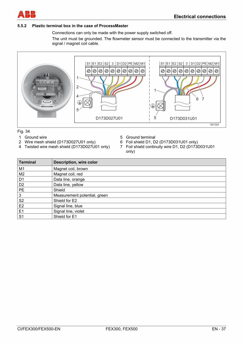
5.5.2 Plastic terminal box in the case of ProcessMaster
Connections can only be made with the power supply switched off.
The unit must be grounded. The flowmeter sensor must be connected to the transmitter via the signal / magnet coil cable.
G01324
S1 E1 E2 S2 3 D1 D2 PE M2 M1 S1 E1 E2 S2 3 D1 D2 PE M2 M1
D173D031U01D173D027U01
1
2
4
5
1
5
6 7
Fig. 34
1 Ground wire 2 Wire mesh shield (D173D027U01 only) 4 Twisted wire mesh shield (D173D027U01 only)
5 Ground terminal 6 Foil shield D1, D2 (D173D031U01 only) 7 Foil shield continuity wire D1, D2 (D173D031U01
only)
Terminal Description, wire color
M1 Magnet coil, brown M2 Magnet coil, red D1 Data line, orange D2 Data line, yellow PE Shield 3 Measurement potential, green S2 Shield for E2 E2 Signal line, blue E1 Signal line, violet S1 Shield for E1
Electrical connections
38 - EN FEX300, FEX500 CI/FEX300/FEX500-EN
IMPORTANT (NOTE)
• Use wire end sleeves.
- Wire end sleeves 0.75 mm2 (AWG 19), for shielding (S1, S2)
- Wire end sleeves 0.5 mm2 (AWG 20), for all other wires
• The shields may not touch (signal short circuit). en
Connect the cable end on the flowmeter sensor side as shown in Fig. 34.
Cable with part number D173D027U01
• Twist the wire mesh shield of the cable and connect to the ground terminal.
• Connect the ground wire of the cable to the SE clamp of the terminal strip.
• Connect all other wires as shown in Fig. 34.
Cable with part number D173D031U01
• Connect the cable ground wire together with the foil shield continuity wire from D1, D2 to the SE clamp of the terminal strip.
• When using the flowmeter sensor in systems with cathodic corrosion protection (CCP), connect the cable ground wire together with the foil shield continuity wire from D1, D2 to the PE clamp of the terminal strip.
• Connect all other wires as shown in Fig. 34.
5.5.3 Connection via cable conduit
NOTICE - Condensate formation in terminal box
If the flowmeter sensor is permanently connected to cable conduits, there is a possibility that moisture may get into the terminal box as a result of condensate formation in the cable conduit.
Ensure that the cable entry points on the terminal box are sealed.
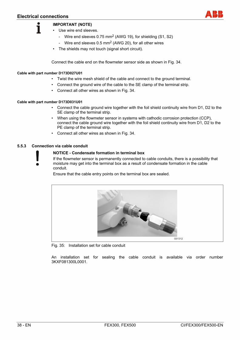
Fig. 35: Installation set for cable conduit
An installation set for sealing the cable conduit is available via order number 3KXF081300L0001.
G01312
Electrical connections
CI/FEX300/FEX500-EN FEX300, FEX500 EN - 39
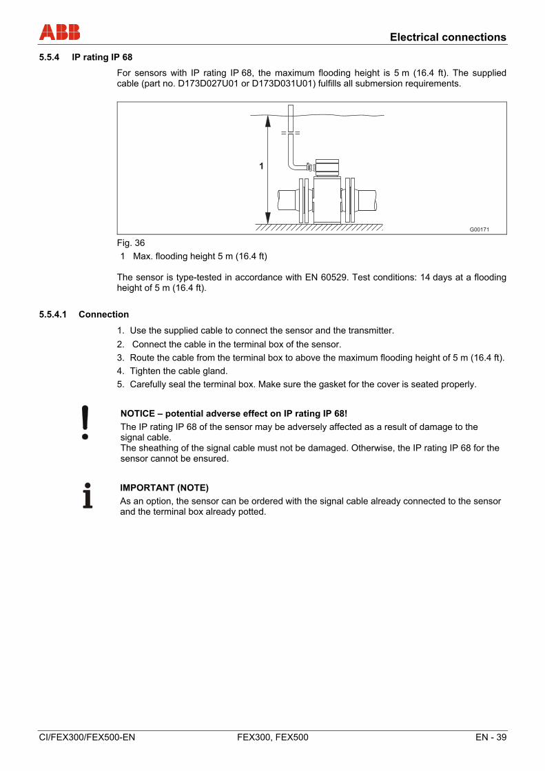
5.5.4 IP rating IP 68
For sensors with IP rating IP 68, the maximum flooding height is 5 m (16.4 ft). The supplied cable (part no. D173D027U01 or D173D031U01) fulfills all submersion requirements.
G00171
1
Fig. 36
1 Max. flooding height 5 m (16.4 ft) The sensor is type-tested in accordance with EN 60529. Test conditions: 14 days at a flooding height of 5 m (16.4 ft).
5.5.4.1 Connection
1. Use the supplied cable to connect the sensor and the transmitter.
2. Connect the cable in the terminal box of the sensor.
3. Route the cable from the terminal box to above the maximum flooding height of 5 m (16.4 ft).
4. Tighten the cable gland.
5. Carefully seal the terminal box. Make sure the gasket for the cover is seated properly.
NOTICE – potential adverse effect on IP rating IP 68!
The IP rating IP 68 of the sensor may be adversely affected as a result of damage to the signal cable. The sheathing of the signal cable must not be damaged. Otherwise, the IP rating IP 68 for the sensor cannot be ensured.
IMPORTANT (NOTE)
As an option, the sensor can be ordered with the signal cable already connected to the sensor and the terminal box already potted.
Electrical connections
40 - EN FEX300, FEX500 CI/FEX300/FEX500-EN
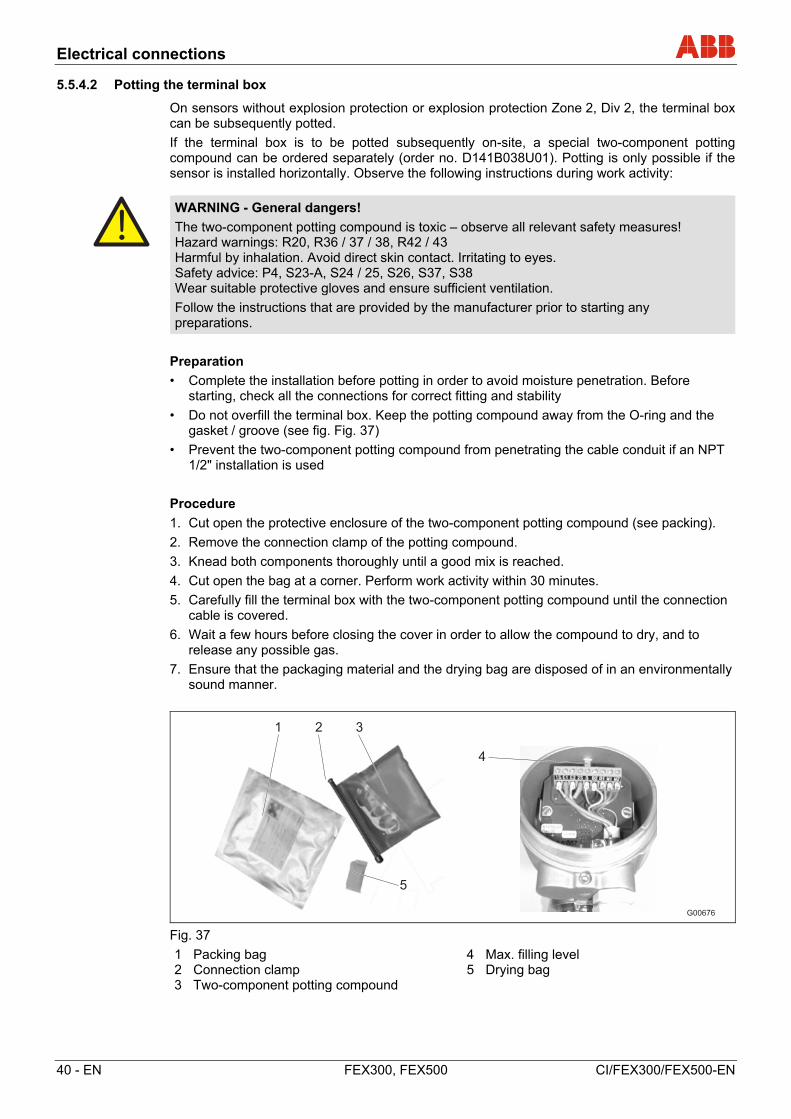
5.5.4.2 Potting the terminal box
On sensors without explosion protection or explosion protection Zone 2, Div 2, the terminal box can be subsequently potted.
If the terminal box is to be potted subsequently on-site, a special two-component potting compound can be ordered separately (order no. D141B038U01). Potting is only possible if the sensor is installed horizontally. Observe the following instructions during work activity:
WARNING - General dangers!
The two-component potting compound is toxic – observe all relevant safety measures! Hazard warnings: R20, R36 / 37 / 38, R42 / 43 Harmful by inhalation. Avoid direct skin contact. Irritating to eyes. Safety advice: P4, S23-A, S24 / 25, S26, S37, S38 Wear suitable protective gloves and ensure sufficient ventilation.
Follow the instructions that are provided by the manufacturer prior to starting any preparations.
Preparation
• Complete the installation before potting in order to avoid moisture penetration. Before starting, check all the connections for correct fitting and stability
• Do not overfill the terminal box. Keep the potting compound away from the O-ring and the gasket / groove (see fig. Fig. 37)
• Prevent the two-component potting compound from penetrating the cable conduit if an NPT 1/2" installation is used
Procedure
1. Cut open the protective enclosure of the two-component potting compound (see packing).
2. Remove the connection clamp of the potting compound.
3. Knead both components thoroughly until a good mix is reached.
4. Cut open the bag at a corner. Perform work activity within 30 minutes.
5. Carefully fill the terminal box with the two-component potting compound until the connection cable is covered.
6. Wait a few hours before closing the cover in order to allow the compound to dry, and to release any possible gas.
7. Ensure that the packaging material and the drying bag are disposed of in an environmentally sound manner.
G00676
1 2 3
4
5
Fig. 37
1 Packing bag 2 Connection clamp 3 Two-component potting compound
4 Max. filling level 5 Drying bag
Electrical connections
CI/FEX300/FEX500-EN FEX300, FEX500 EN - 41
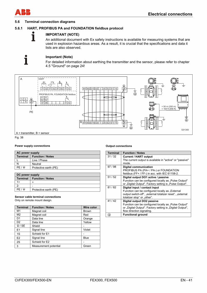
5.6 Terminal connection diagrams
5.6.1 HART, PROFIBUS PA and FOUNDATION fieldbus protocol
IMPORTANT (NOTE)
An additional document with Ex safety instructions is available for measuring systems that are used in explosion hazardous areas. As a result, it is crucial that the specifications and data it lists are also observed.
Important (Note)
For detailed information about earthing the transmitter and the sensor, please refer to chapter 4.5 "Ground" on page 24!
A = transmitter, B = sensor
Fig. 38
Change from one to two columns
Power supply connections
AC power supply Terminal Function / Notes L Live / Phase N Neutral PE / Protective earth (PE)
DC power supply Terminal Function / Notes 1+ + 2- - PE / Protective earth (PE)
Sensor cable terminal connections Only on remote mount design.
Terminal Function / Notes Wire color M1 Magnet coil Brown M2 Magnet coil Red D1 Data line Orange D2 Data line Yellow
/ SE Shield -
E1 Signal line Violet
1S Schield for E1 -
E2 Signal line Blue
2S Schield for E2 -
3 Measurement potential Green
Output connections
Terminal Function / Notes 31 / 32 Current / HART output
The current output is available in "active" or "passive" mode.
97 / 98 Digital communication PROFIBUS PA (PA+ / PA-) or FOUNDATION fieldbus (FF+ / FF-) in acc. with IEC 61158-2.
51 / 52 Digital output DO1 active / passive Function can be configured locally as „Pulse Output" or „Digital Output". Factory setting is „Pulse Output".
81 / 82 Digital input / contact input Function can be configured locally as „External output switch-off“, „external totalizer reset“, „external totalizer stop“ or „other“.
41 / 42 Digital output DO2 passive Function can be configured locally as „Pulse Output" or „Digital Output". Factory setting is „Digital Output", flow direction signaling.
Functional ground
Change from one to two columns
G01350
< 50 m (200 m)< 164 ft (656 ft)
31 32
A
24 V
51 52 81 82 41 42
L N
1+ 2-
M1 M2 D1 D2 3 2S E2 E1 1S
M1 M2 D1 D2 3 E2 E1B
PE
97 98 41 42
PA+ PA-
FF+ FF-
+ -
+ - + - + - + -
HART
PROFIBUS PA, FOUNDATION fieldbus
1S2S
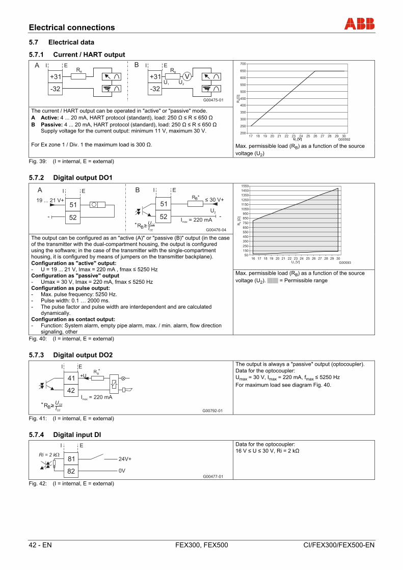
Electrical connections
42 - EN FEX300, FEX500 CI/FEX300/FEX500-EN
5.7 Electrical data
5.7.1 Current / HART output
G00475-01
+31
-32
I EARB
+31
-32
I E
V
BRB
U1 U2
G00592
200
250
300
350
400
450
500
550
600
650
700
17 18 19 20 21 22 23 24 25 26 27 28 29 30U [V]2
R[
]B
Ω
The current / HART output can be operated in "active" or "passive" mode. A Active: 4 ... 20 mA, HART protocol (standard), load: 250 Ω ≤ R ≤ 650 Ω B Passive: 4 ... 20 mA, HART protocol (standard), load: 250 Ω ≤ R ≤ 650 Ω
Supply voltage for the current output: minimum 11 V, maximum 30 V. For Ex zone 1 / Div. 1 the maximum load is 300 Ω. Max. permissible load (RB) as a function of the source
voltage (U2)
Fig. 39: (I = internal, E = external)
5.7.2 Digital output DO1
G00476-04
19 ... 21 V+
-
I E
51
52
ARB*
≤ 30 V+
-
RB* U
CE
ICE
I E
51
52
B
U2
I = 220 mAmax
G00593
50
150
250
350
450
550
650
750
850
950
1050
1150
1250
1350
1450
1550
16 17 18 19 20 21 22 23 24 25 26 27 28 29 30U [V]2
R[
]B
Ω
The output can be configured as an "active (A)" or "passive (B)" output (in the case of the transmitter with the dual-compartment housing, the output is configured using the software; in the case of the transmitter with the single-compartment housing, it is configured by means of jumpers on the transmitter backplane). Configuration as "active" output: - U = 19 ... 21 V, Imax = 220 mA , fmax ≤ 5250 Hz Configuration as "passive" output - Umax = 30 V, Imax = 220 mA, fmax ≤ 5250 Hz Configuration as pulse output: - Max. pulse frequency: 5250 Hz. - Pulse width: 0.1 … 2000 ms. - The pulse factor and pulse width are interdependent and are calculated
dynamically. Configuration as contact output: - Function: System alarm, empty pipe alarm, max. / min. alarm, flow direction
signaling, other
Max. permissible load (RB) as a function of the source voltage (U2). = Permissible range
Fig. 40: (I = internal, E = external)
5.7.3 Digital output DO2
G00792-01
RB*
RB* U
CE
ICE
+U
I E
41
42I = 220 mAmax
The output is always a "passive" output (optocoupler). Data for the optocoupler: Umax = 30 V, Imax = 220 mA, fmax ≤ 5250 Hz
For maximum load see diagram Fig. 40.
Fig. 41: (I = internal, E = external)
5.7.4 Digital input DI
G00477-01
24V+
0V
Ri = 2 k
I E
81
82
Data for the optocoupler: 16 V ≤ U ≤ 30 V, Ri = 2 kΩ
Fig. 42: (I = internal, E = external)
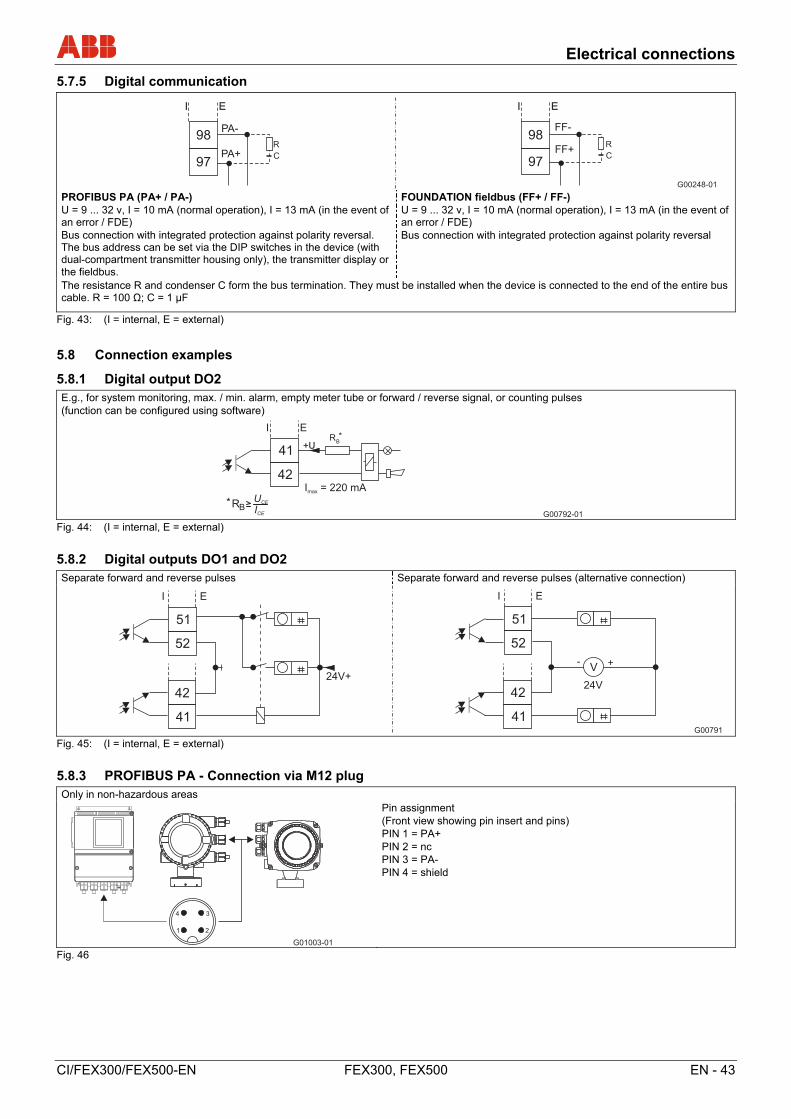
Electrical connections
CI/FEX300/FEX500-EN FEX300, FEX500 EN - 43
5.7.5 Digital communication
G00248-01
FF-
FF+R
C97
98
I E
97
PA-
R
CPA+
98
I E
PROFIBUS PA (PA+ / PA-) U = 9 ... 32 v, I = 10 mA (normal operation), I = 13 mA (in the event of an error / FDE) Bus connection with integrated protection against polarity reversal. The bus address can be set via the DIP switches in the device (with dual-compartment transmitter housing only), the transmitter display or the fieldbus.
FOUNDATION fieldbus (FF+ / FF-) U = 9 ... 32 v, I = 10 mA (normal operation), I = 13 mA (in the event of an error / FDE) Bus connection with integrated protection against polarity reversal
The resistance R and condenser C form the bus termination. They must be installed when the device is connected to the end of the entire bus cable. R = 100 Ω; C = 1 µF
Fig. 43: (I = internal, E = external)
5.8 Connection examples
5.8.1 Digital output DO2
E.g., for system monitoring, max. / min. alarm, empty meter tube or forward / reverse signal, or counting pulses (function can be configured using software)
G00792-01
RB*
RB* U
CE
ICE
+U
I E
41
42I = 220 mAmax
Fig. 44: (I = internal, E = external)
5.8.2 Digital outputs DO1 and DO2
Separate forward and reverse pulses Separate forward and reverse pulses (alternative connection)
G00791
24V+
I E
51
52
41
4224V
I E
51
52
41
42
V +-
Fig. 45: (I = internal, E = external)
5.8.3 PROFIBUS PA - Connection via M12 plug
Only in non-hazardous areas
G01003-01
1 2
34
Pin assignment (Front view showing pin insert and pins) PIN 1 = PA+ PIN 2 = nc PIN 3 = PA- PIN 4 = shield
Fig. 46
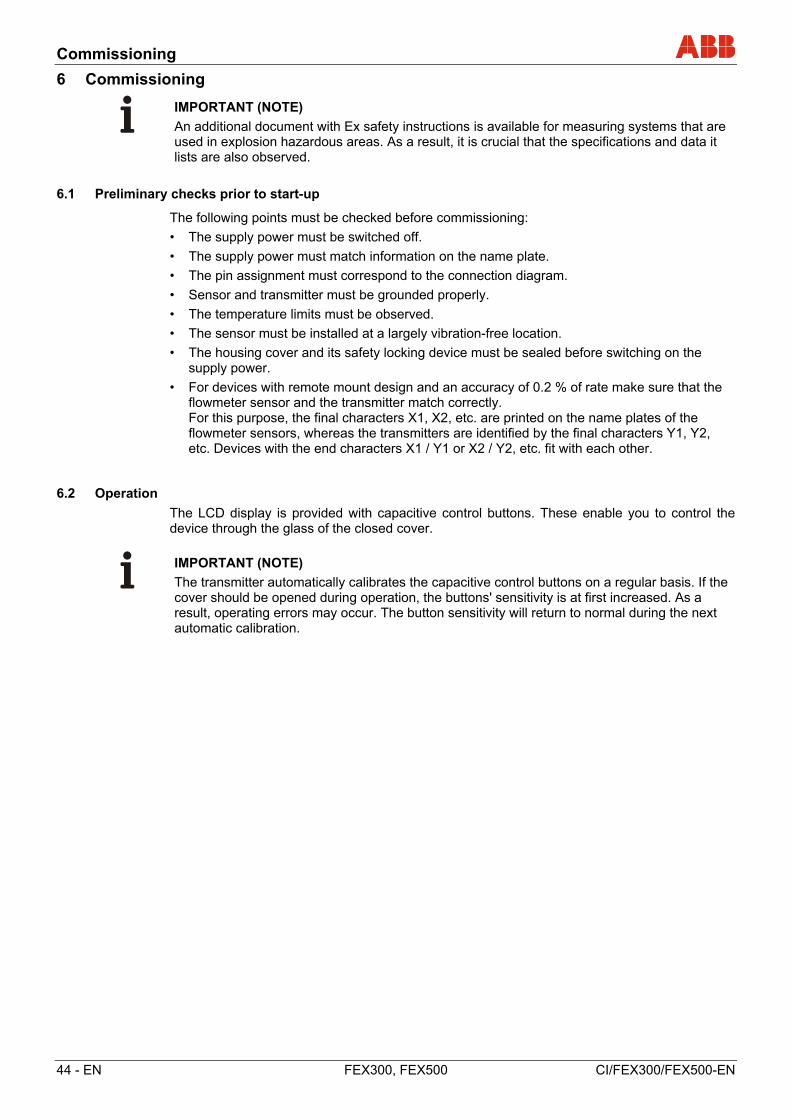
Commissioning
44 - EN FEX300, FEX500 CI/FEX300/FEX500-EN
6 Commissioning
IMPORTANT (NOTE)
An additional document with Ex safety instructions is available for measuring systems that are used in explosion hazardous areas. As a result, it is crucial that the specifications and data it lists are also observed.
6.1 Preliminary checks prior to start-up
The following points must be checked before commissioning:
• The supply power must be switched off.
• The supply power must match information on the name plate.
• The pin assignment must correspond to the connection diagram.
• Sensor and transmitter must be grounded properly.
• The temperature limits must be observed.
• The sensor must be installed at a largely vibration-free location.
• The housing cover and its safety locking device must be sealed before switching on the supply power.
• For devices with remote mount design and an accuracy of 0.2 % of rate make sure that the flowmeter sensor and the transmitter match correctly. For this purpose, the final characters X1, X2, etc. are printed on the name plates of the flowmeter sensors, whereas the transmitters are identified by the final characters Y1, Y2, etc. Devices with the end characters X1 / Y1 or X2 / Y2, etc. fit with each other.
6.2 Operation
The LCD display is provided with capacitive control buttons. These enable you to control the device through the glass of the closed cover.
IMPORTANT (NOTE)
The transmitter automatically calibrates the capacitive control buttons on a regular basis. If the cover should be opened during operation, the buttons' sensitivity is at first increased. As a result, operating errors may occur. The button sensitivity will return to normal during the next automatic calibration.
Commissioning
CI/FEX300/FEX500-EN FEX300, FEX500 EN - 45
6.2.1 Menu navigation
G00822-01
1
2 -----------------Menu----------------
3
4
5 Exit Select 5
Fig. 47: LCD-indicator
1 Control buttons for menu navigation 2 Menu name 3 Menu number
4 Marker for indicating relative position within the menu
5 Function currently assigned to the
and control buttons
You can use the or control buttons to browse through the menu or select a number or character within a parameter value.
Different functions can be assigned to the and control buttons. The function that is currently assigned to them (5) is shown on the display.
6.2.1.1 Control button functions
Meaning
Exit Exit menu
Back Go back one submenu
Cancel Cancel a parameter entry
Next Select the next position for entering numerical and alphanumeric values
Meaning
Select Select submenu / parameter
Edit Edit parameter
OK Save parameter entered
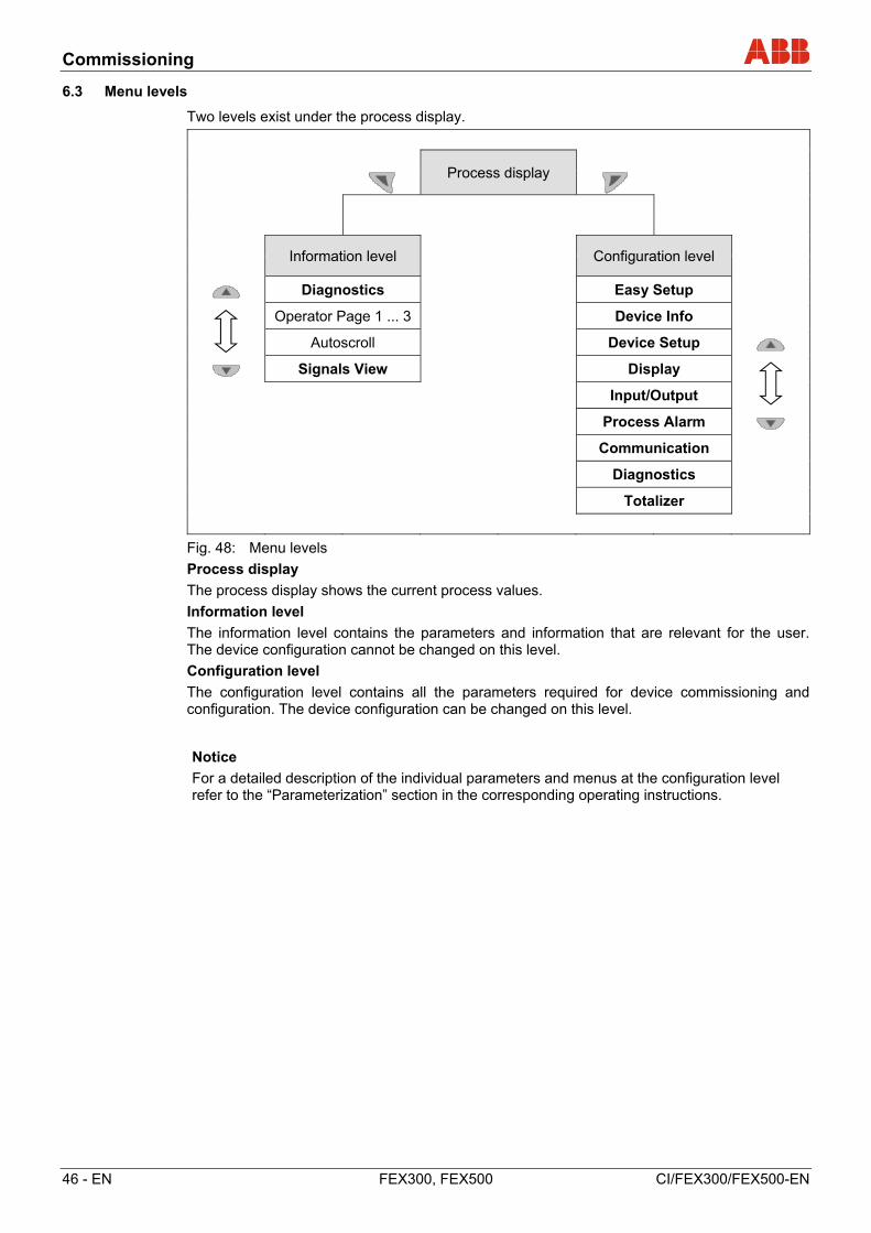
Commissioning
46 - EN FEX300, FEX500 CI/FEX300/FEX500-EN
6.3 Menu levels
Two levels exist under the process display.
Process display
Information level
Configuration level
Diagnostics Easy Setup
Operator Page 1 ... 3 Device Info
Autoscroll Device Setup
Signals View Display
Input/Output
Process Alarm
Communication
Diagnostics
Totalizer
Fig. 48: Menu levels
Process display
The process display shows the current process values.
Information level
The information level contains the parameters and information that are relevant for the user. The device configuration cannot be changed on this level.
Configuration level
The configuration level contains all the parameters required for device commissioning and configuration. The device configuration can be changed on this level.
Notice
For a detailed description of the individual parameters and menus at the configuration level refer to the “Parameterization” section in the corresponding operating instructions.
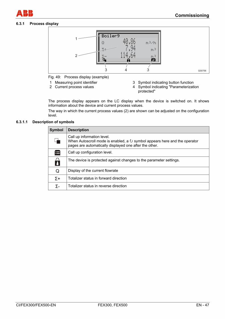
Commissioning
CI/FEX300/FEX500-EN FEX300, FEX500 EN - 47
6.3.1 Process display
G00756
1
2
3 4 3
Fig. 49: Process display (example)
1 Measuring point identifier 2 Current process values
3 Symbol indicating button function 4 Symbol indicating "Parameterization
protected"
The process display appears on the LC display when the device is switched on. It shows information about the device and current process values.
The way in which the current process values (2) are shown can be adjusted on the configuration level.
6.3.1.1 Description of symbols
Symbol Description
Call up information level. When Autoscroll mode is enabled, a symbol appears here and the operator pages are automatically displayed one after the other.
Call up configuration level.
The device is protected against changes to the parameter settings.
Q Display of the current flowrate
Σ+ Totalizer status in forward direction
Σ- Totalizer status in reverse direction
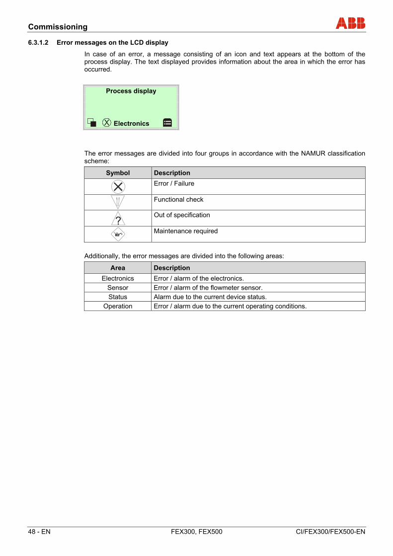
Commissioning
48 - EN FEX300, FEX500 CI/FEX300/FEX500-EN
6.3.1.2 Error messages on the LCD display
In case of an error, a message consisting of an icon and text appears at the bottom of the process display. The text displayed provides information about the area in which the error has occurred.
Process display
Electronics
The error messages are divided into four groups in accordance with the NAMUR classification scheme:
Symbol Description
Error / Failure
Functional check
Out of specification
Maintenance required
Additionally, the error messages are divided into the following areas:
Area Description
Electronics Error / alarm of the electronics.
Sensor Error / alarm of the flowmeter sensor.
Status Alarm due to the current device status.
Operation Error / alarm due to the current operating conditions.
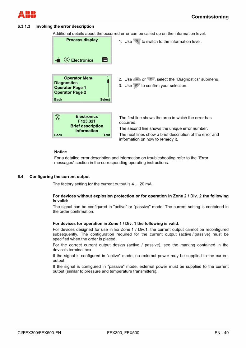
Commissioning
CI/FEX300/FEX500-EN FEX300, FEX500 EN - 49
6.3.1.3 Invoking the error description
Additional details about the occurred error can be called up on the information level.
Process display 1. Use to switch to the information level.
Electronics
Operator Menu
2. Use or , select the "Diagnostics" submenu.
3. Use to confirm your selection. Diagnostics Operator Page 1 Operator Page 2
Back Select
Electronics The first line shows the area in which the error has occurred.
The second line shows the unique error number.
The next lines show a brief description of the error and information on how to remedy it.
F123,321 Brief description
Information Back Exit
Notice
For a detailed error description and information on troubleshooting refer to the “Error messages” section in the corresponding operating instructions.
6.4 Configuring the current output
The factory setting for the current output is 4 ... 20 mA.
For devices without explosion protection or for operation in Zone 2 / Div. 2 the following is valid:
The signal can be configured in "active" or "passive" mode. The current setting is contained in the order confirmation.
For devices for operation in Zone 1 / Div. 1 the following is valid:
For devices designed for use in Ex Zone 1 / Div.1, the current output cannot be reconfigured subsequently. The configuration required for the current output (active / passive) must be specified when the order is placed.
For the correct current output design (active / passive), see the marking contained in the device's terminal box.
If the signal is configured in "active" mode, no external power may be supplied to the current output.
If the signal is configured in "passive" mode, external power must be supplied to the current output (similar to pressure and temperature transmitters).
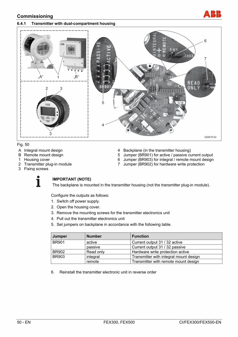
Commissioning
50 - EN FEX300, FEX500 CI/FEX300/FEX500-EN
6.4.1 Transmitter with dual-compartment housing
G00679-02
5
4
„A“ „B“1
2 3
3
6
7
Fig. 50
A Integral mount design B Remote mount design 1 Housing cover 2 Transmitter plug-in module 3 Fixing screws
4 Backplane (in the transmitter housing) 5 Jumper (BR901) for active / passive current output 6 Jumper (BR903) for integral / remote mount design 7 Jumper (BR902) for hardware write protection
IMPORTANT (NOTE)
The backplane is mounted in the transmitter housing (not the transmitter plug-in module).
Configure the outputs as follows:
1. Switch off power supply.
2. Open the housing cover.
3. Remove the mounting screws for the transmitter electronics unit
4. Pull out the transmitter electronics unit
5. Set jumpers on backplane in accordance with the following table.
Jumper Number Function
BR901 active Current output 31 / 32 active passive Current output 31 / 32 passive BR902 Read only Hardware write protection active BR903 integral Transmitter with integral mount design remote Transmitter with remote mount design
6. Reinstall the transmitter electronic unit in reverse order
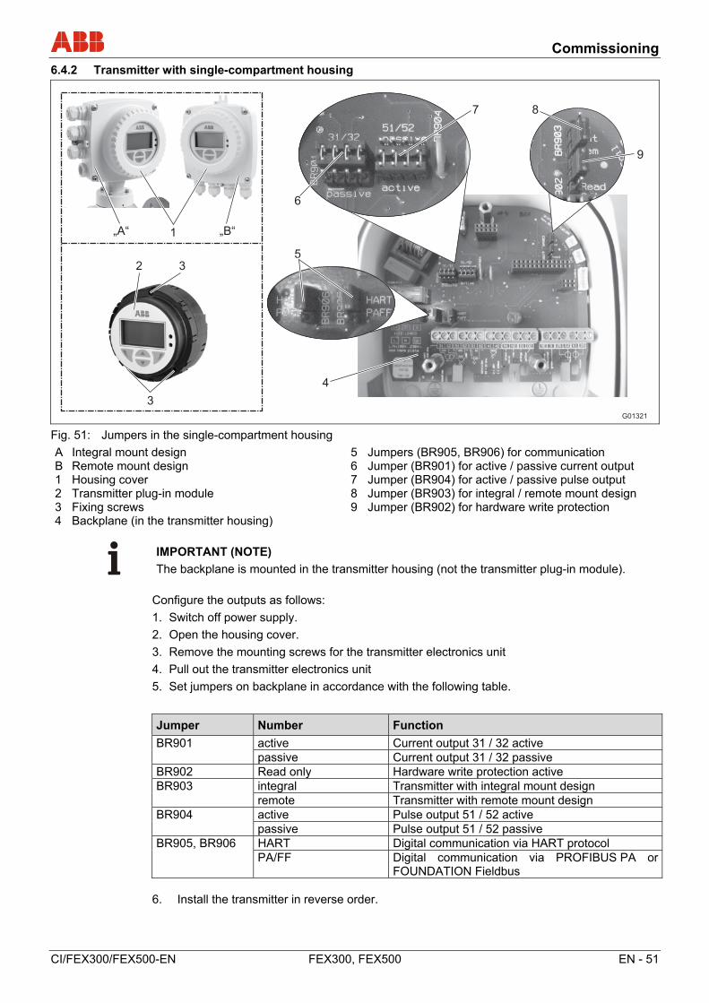
Commissioning
CI/FEX300/FEX500-EN FEX300, FEX500 EN - 51
6.4.2 Transmitter with single-compartment housing
G01321
„A“ „B“1
2 3
3
4
6
5
7 8
9
Fig. 51: Jumpers in the single-compartment housing
A Integral mount design B Remote mount design 1 Housing cover 2 Transmitter plug-in module 3 Fixing screws 4 Backplane (in the transmitter housing)
5 Jumpers (BR905, BR906) for communication 6 Jumper (BR901) for active / passive current output 7 Jumper (BR904) for active / passive pulse output 8 Jumper (BR903) for integral / remote mount design 9 Jumper (BR902) for hardware write protection
IMPORTANT (NOTE)
The backplane is mounted in the transmitter housing (not the transmitter plug-in module).
Configure the outputs as follows:
1. Switch off power supply.
2. Open the housing cover.
3. Remove the mounting screws for the transmitter electronics unit
4. Pull out the transmitter electronics unit
5. Set jumpers on backplane in accordance with the following table.
Jumper Number Function
BR901 active Current output 31 / 32 active passive Current output 31 / 32 passive BR902 Read only Hardware write protection active BR903 integral Transmitter with integral mount design remote Transmitter with remote mount design BR904 active Pulse output 51 / 52 active passive Pulse output 51 / 52 passive BR905, BR906 HART Digital communication via HART protocol PA/FF Digital communication via PROFIBUS PA or
FOUNDATION Fieldbus 6. Install the transmitter in reverse order.
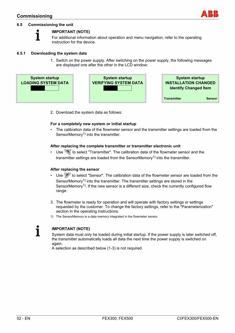
Commissioning
52 - EN FEX300, FEX500 CI/FEX300/FEX500-EN
6.5 Commissioning the unit
IMPORTANT (NOTE)
For additional information about operation and menu navigation, refer to the operating instruction for the device.
6.5.1 Downloading the system data
1. Switch on the power supply. After switching on the power supply, the following messages are displayed one after the other in the LCD window:
System startup System startup System startup LOADING SYSTEM DATA VERIFYING SYSTEM DATA INSTALLATION CHANGED
Identify Changed Item
Transmitter Sensor
2. Download the system data as follows:
For a completely new system or initial startup
• The calibration data of the flowmeter sensor and the transmitter settings are loaded from the SensorMemory1) into the transmitter.
After replacing the complete transmitter or transmitter electronic unit
• Use to select "Transmitter". The calibration data of the flowmeter sensor and the
transmitter settings are loaded from the SensorMemory1) into the transmitter.
After replacing the sensor
• Use to select "Sensor". The calibration data of the flowmeter sensor are loaded from the
SensorMemory1) into the transmitter. The transmitter settings are stored in the SensorMemory1). If the new sensor is a different size, check the currently configured flow range.
3. The flowmeter is ready for operation and will operate with factory settings or settings requested by the customer. To change the factory settings, refer to the "Parameterization" section in the operating instructions.
1) The SensorMemory is a data memory integrated in the flowmeter sensor.
IMPORTANT (NOTE)
System data must only be loaded during initial startup. If the power supply is later switched off, the transmitter automatically loads all data the next time the power supply is switched on again. A selection as described below (1-3) is not required.
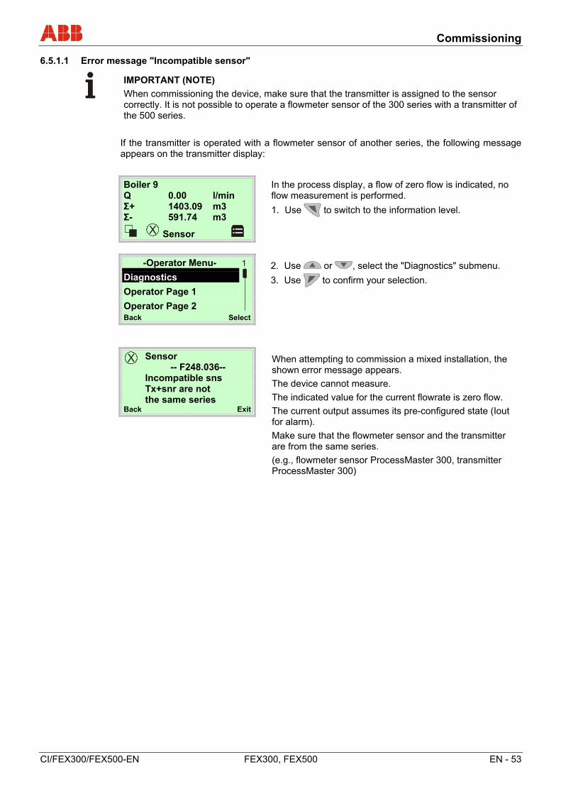
Commissioning
CI/FEX300/FEX500-EN FEX300, FEX500 EN - 53
6.5.1.1 Error message "Incompatible sensor"
IMPORTANT (NOTE)
When commissioning the device, make sure that the transmitter is assigned to the sensor correctly. It is not possible to operate a flowmeter sensor of the 300 series with a transmitter of the 500 series.
If the transmitter is operated with a flowmeter sensor of another series, the following message appears on the transmitter display:
-Operator Menu-
2. Use or , select the "Diagnostics" submenu.
3. Use to confirm your selection. Diagnostics
Operator Page 1
Operator Page 2 Back Select
Sensor When attempting to commission a mixed installation, the shown error message appears.
The device cannot measure.
The indicated value for the current flowrate is zero flow.
The current output assumes its pre-configured state (Iout for alarm).
Make sure that the flowmeter sensor and the transmitter are from the same series.
(e.g., flowmeter sensor ProcessMaster 300, transmitter ProcessMaster 300)
-- F248.036-- Incompatible sns Tx+snr are not the same series
Back Exit
Boiler 9 In the process display, a flow of zero flow is indicated, no flow measurement is performed.
1. Use to switch to the information level.
Q 0.00 l/min Σ+ 1403.09 m3 Σ- 591.74 m3
Sensor
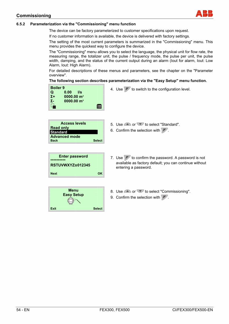
Commissioning
54 - EN FEX300, FEX500 CI/FEX300/FEX500-EN
6.5.2 Parameterization via the "Commissioning" menu function
The device can be factory parameterized to customer specifications upon request.
If no customer information is available, the device is delivered with factory settings.
The setting of the most current parameters is summarized in the "Commissioning" menu. This menu provides the quickest way to configure the device.
The "Commissioning" menu allows you to select the language, the physical unit for flow rate, the measuring range, the totalizer unit, the pulse / frequency mode, the pulse per unit, the pulse width, damping, and the status of the current output during an alarm (Iout for alarm, Iout: Low Alarm, Iout: High Alarm).
For detailed descriptions of these menus and parameters, see the chapter on the "Parameter overview".
The following section describes parameterization via the "Easy Setup" menu function.
Boiler 9
4. Use to switch to the configuration level.
Q 0.00 l/s Σ+ 0000.00 m³ Σ- 0000.00 m³
Access levels
5. Use or to select "Standard".
6. Confirm the selection with .
Read only Standard Advanced mode Back Select
Enter password
7. Use to confirm the password. A password is not available as factory default; you can continue without entering a password.
********** RSTUVWXYZ012345 Next OK
Menu
8. Use or to select "Commissioning".
9. Confirm the selection with . Easy Setup
Exit Select
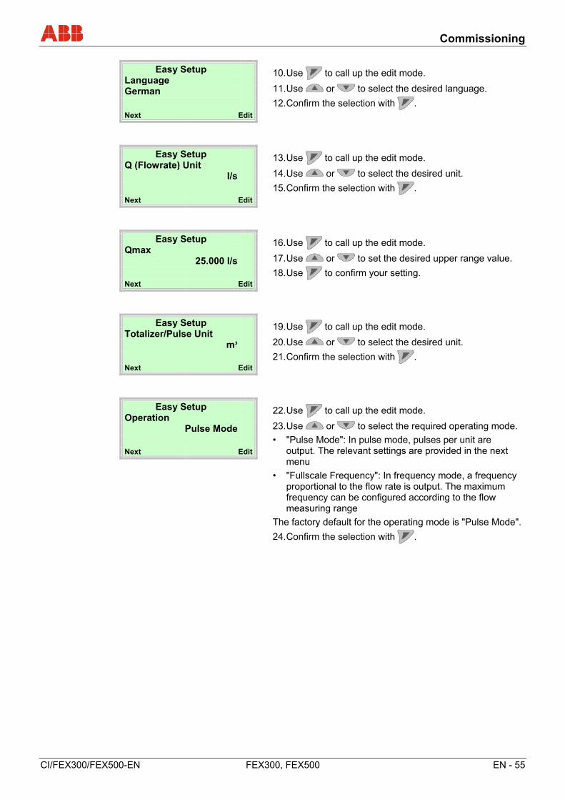
Commissioning
CI/FEX300/FEX500-EN FEX300, FEX500 EN - 55
Easy Setup
10. Use to call up the edit mode.
11. Use or to select the desired language.
12. Confirm the selection with .
Language German
Next Edit
Easy Setup
13. Use to call up the edit mode.
14. Use or to select the desired unit.
15. Confirm the selection with .
Q (Flowrate) Unit l/s
Next Edit
Easy Setup
16. Use to call up the edit mode.
17. Use or to set the desired upper range value.
18. Use to confirm your setting.
Qmax 25.000 l/s
Next Edit
Easy Setup
19. Use to call up the edit mode.
20. Use or to select the desired unit.
21. Confirm the selection with .
Totalizer/Pulse Unit m³
Next Edit
Easy Setup
22. Use to call up the edit mode.
23. Use or to select the required operating mode.
• "Pulse Mode": In pulse mode, pulses per unit are output. The relevant settings are provided in the next menu
• "Fullscale Frequency": In frequency mode, a frequency proportional to the flow rate is output. The maximum frequency can be configured according to the flow measuring range
The factory default for the operating mode is "Pulse Mode".
24. Confirm the selection with .
Operation Pulse Mode
Next Edit
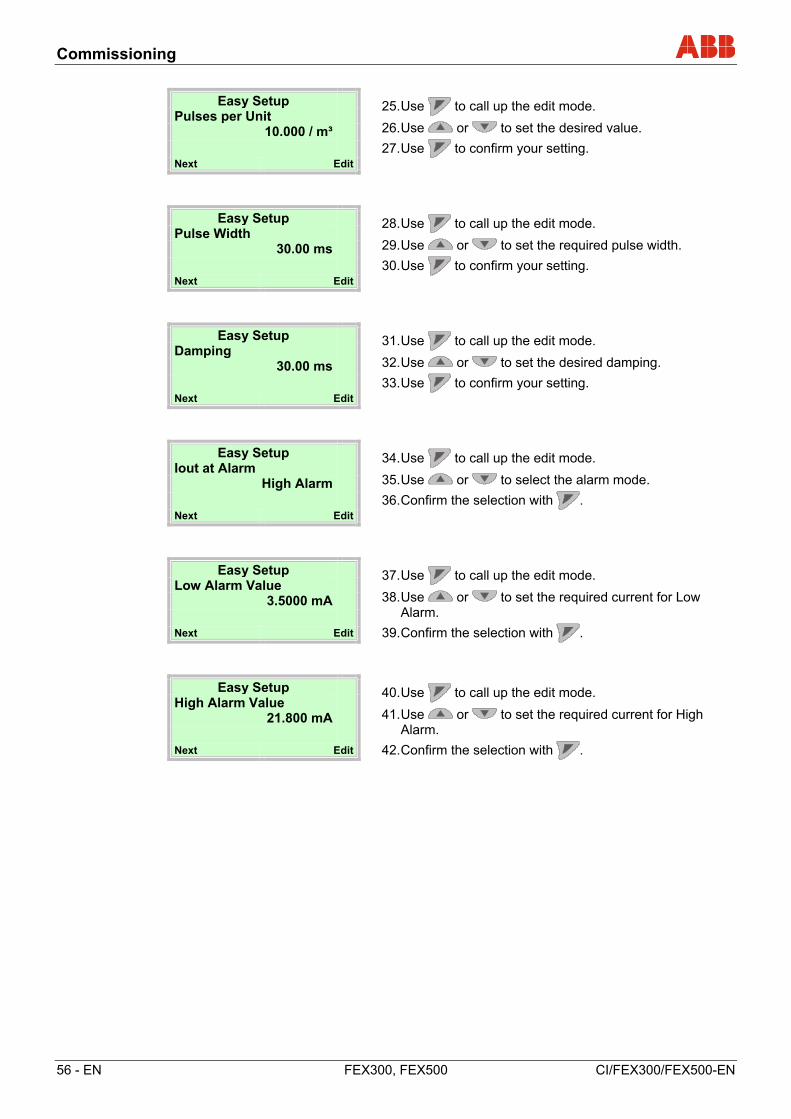
Commissioning
56 - EN FEX300, FEX500 CI/FEX300/FEX500-EN
Easy Setup
25. Use to call up the edit mode.
26. Use or to set the desired value.
27. Use to confirm your setting.
Pulses per Unit 10.000 / m³
Next Edit
Easy Setup
28. Use to call up the edit mode.
29. Use or to set the required pulse width.
30. Use to confirm your setting.
Pulse Width 30.00 ms
Next Edit
Easy Setup
31. Use to call up the edit mode.
32. Use or to set the desired damping.
33. Use to confirm your setting.
Damping 30.00 ms
Next Edit
Easy Setup
34. Use to call up the edit mode.
35. Use or to select the alarm mode.
36. Confirm the selection with .
Iout at Alarm High Alarm
Next Edit
Easy Setup
37. Use to call up the edit mode.
38. Use or to set the required current for Low Alarm.
39. Confirm the selection with .
Low Alarm Value 3.5000 mA
Next Edit
Easy Setup
40. Use to call up the edit mode.
41. Use or to set the required current for High Alarm.
42. Confirm the selection with .
High Alarm Value 21.800 mA
Next Edit
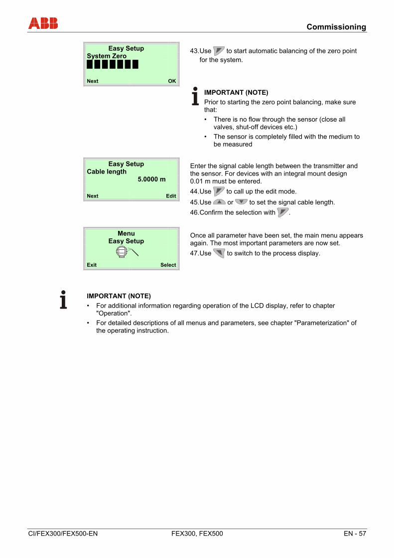
Commissioning
CI/FEX300/FEX500-EN FEX300, FEX500 EN - 57
Easy Setup
43. Use to start automatic balancing of the zero point for the system.
System Zero
Next OK
IMPORTANT (NOTE)
Prior to starting the zero point balancing, make sure that:
• There is no flow through the sensor (close all valves, shut-off devices etc.)
• The sensor is completely filled with the medium to be measured
Easy Setup
Enter the signal cable length between the transmitter and the sensor. For devices with an integral mount design 0.01 m must be entered.
44. Use to call up the edit mode.
45. Use or to set the signal cable length.
46. Confirm the selection with .
Cable length 5.0000 m
Next Edit
Menu
Once all parameter have been set, the main menu appears again. The most important parameters are now set.
47. Use to switch to the process display.
Easy Setup
Exit Select
IMPORTANT (NOTE)
• For additional information regarding operation of the LCD display, refer to chapter "Operation".
• For detailed descriptions of all menus and parameters, see chapter "Parameterization" of the operating instruction.
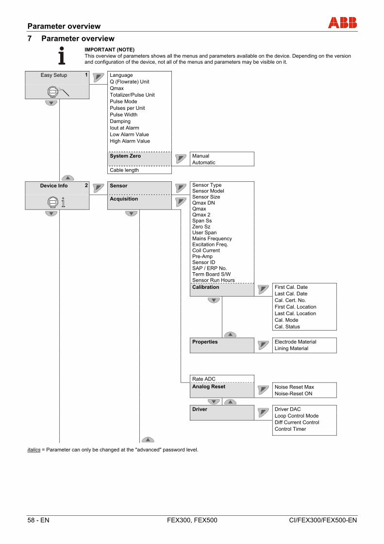
Parameter overview
58 - EN FEX300, FEX500 CI/FEX300/FEX500-EN
7 Parameter overview
IMPORTANT (NOTE) This overview of parameters shows all the menus and parameters available on the device. Depending on the version and configuration of the device, not all of the menus and parameters may be visible on it.
Easy Setup 1
Language Q (Flowrate) Unit Qmax Totalizer/Pulse Unit Pulse Mode Pulses per Unit Pulse Width Damping Iout at Alarm Low Alarm Value High Alarm Value
System Zero
Manual Automatic
Cable length
Device Info 2
Sensor
Sensor Type Sensor Model Sensor Size Qmax DN Qmax Qmax 2 Span Ss Zero Sz User Span Mains Frequency Excitation Freq. Coil Current Pre-Amp Sensor ID SAP / ERP No. Term Board S/W Sensor Run Hours
Acquisition
Calibration
First Cal. Date Last Cal. Date Cal. Cert. No. First Cal. Location Last Cal. Location Cal. Mode Cal. Status
Properties
Electrode Material Lining Material
Rate ADC
Analog Reset
Noise Reset Max Noise-Reset ON
Driver
Driver DAC Loop Control Mode Diff Current Control Control Timer
italics = Parameter can only be changed at the "advanced" password level.
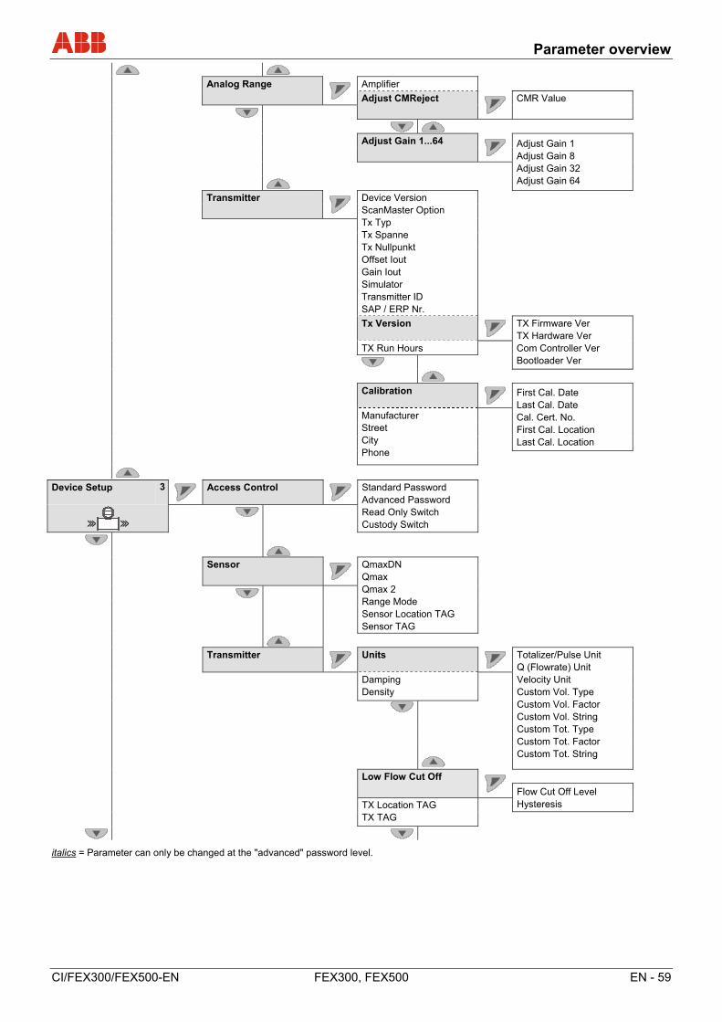
Parameter overview
CI/FEX300/FEX500-EN FEX300, FEX500 EN - 59
Analog Range
Amplifier
Adjust CMReject
CMR Value
Adjust Gain 1...64 Adjust Gain 1
Adjust Gain 8 Adjust Gain 32 Adjust Gain 64
Transmitter
Device Version ScanMaster Option Tx Typ Tx Spanne Tx Nullpunkt Offset Iout Gain Iout Simulator Transmitter ID SAP / ERP Nr.
Tx Version
TX Firmware Ver TX Hardware Ver Com Controller Ver Bootloader Ver
TX Run Hours
Calibration
First Cal. Date Last Cal. Date Cal. Cert. No. First Cal. Location Last Cal. Location
Manufacturer Street City Phone
Device Setup 3
Access Control
Standard Password Advanced Password Read Only Switch Custody Switch
Sensor
QmaxDN Qmax Qmax 2 Range Mode Sensor Location TAG Sensor TAG
Transmitter
Units
Totalizer/Pulse Unit Q (Flowrate) Unit Velocity Unit Custom Vol. Type Custom Vol. Factor Custom Vol. String Custom Tot. Type Custom Tot. Factor Custom Tot. String
Damping Density
Low Flow Cut Off
Flow Cut Off Level Hysteresis
TX Location TAG TX TAG
italics = Parameter can only be changed at the "advanced" password level.
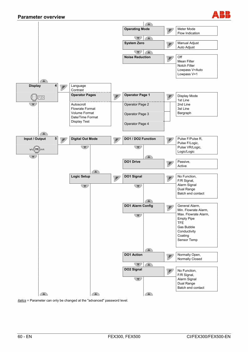
Parameter overview
60 - EN FEX300, FEX500 CI/FEX300/FEX500-EN
Operating Mode
Meter Mode Flow Indication
System Zero
Manual Adjust Auto Adjust
Noise Reduction
Off Mean Filter Notch Filter Lowpass V=Auto Lowpass V=1
Display 4
Language Contrast
Operator Pages
Operator Page 1 Display Mode
1st Line 2nd Line 3st Line Bargraph
Autoscroll Flowrate Format Volume Format Date/Time Format Display Test
Operator Page 2
Operator Page 3
Operator Page 4
Input / Output 5
Digital Out Mode
DO1 / DO2 Function
Pulse F/Pulse R, Pulse F/Logic, Pulse VR/Logic, Logic/Logic
DO1 Drive
Passive, Active
Logic Setup
DO1 Signal
No Function, F/R Signal, Alarm Signal Dual Range Batch end contact
DO1 Alarm Config
General Alarm, Min. Flowrate Alarm, Max. Flowrate Alarm, Empty Pipe TFE Gas Bubble Conductivity Coating Sensor Temp
DO1 Action
Normally Open, Normally Closed
DO2 Signal No Function,
F/R Signal, Alarm Signal Dual Range Batch end contact
italics = Parameter can only be changed at the "advanced" password level.
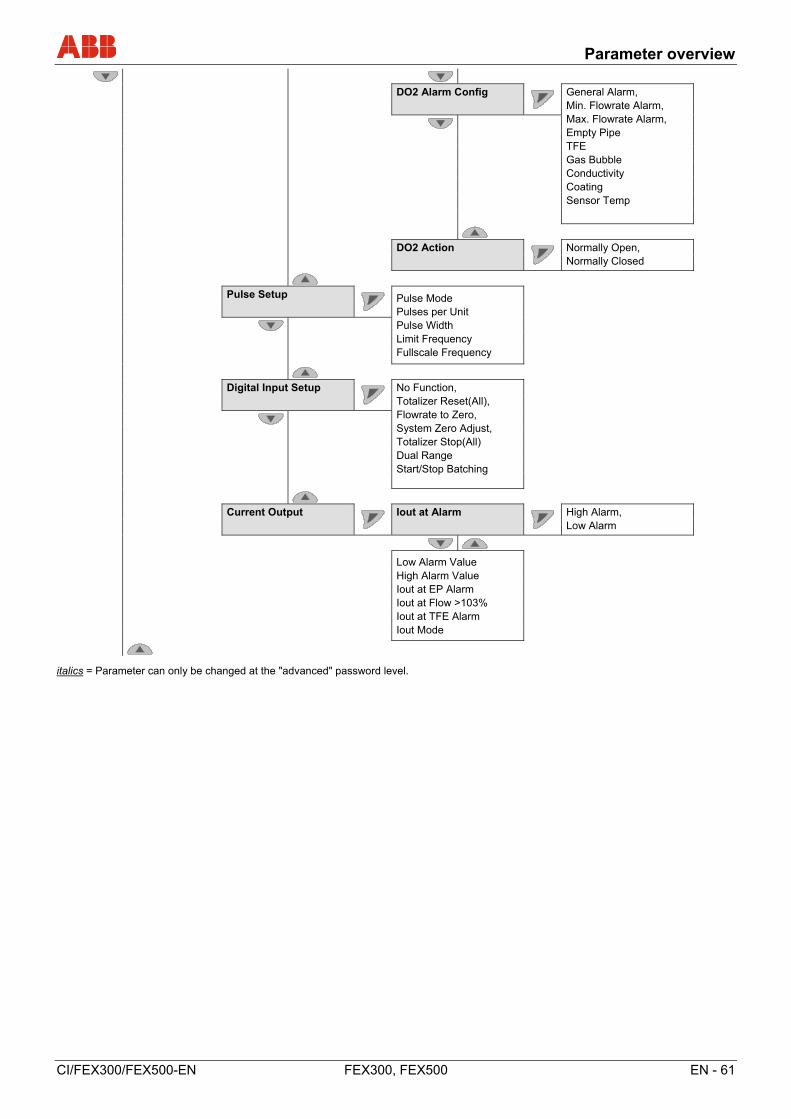
Parameter overview
CI/FEX300/FEX500-EN FEX300, FEX500 EN - 61
DO2 Alarm Config
General Alarm, Min. Flowrate Alarm, Max. Flowrate Alarm, Empty Pipe TFE Gas Bubble Conductivity Coating Sensor Temp
DO2 Action
Normally Open, Normally Closed
Pulse Setup Pulse Mode
Pulses per Unit Pulse Width Limit Frequency Fullscale Frequency
Digital Input Setup
No Function, Totalizer Reset(All), Flowrate to Zero, System Zero Adjust, Totalizer Stop(All) Dual Range Start/Stop Batching
Current Output
Iout at Alarm
High Alarm, Low Alarm
Low Alarm Value High Alarm Value Iout at EP Alarm Iout at Flow >103% Iout at TFE Alarm Iout Mode
italics = Parameter can only be changed at the "advanced" password level.
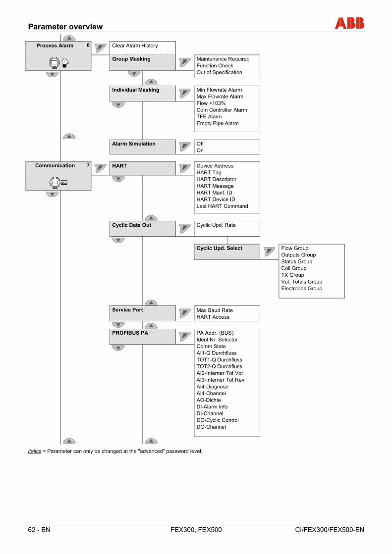
Parameter overview
62 - EN FEX300, FEX500 CI/FEX300/FEX500-EN
Process Alarm 6
Clear Alarm History
Group Masking
Maintenance Required Function Check Out of Specification
Individual Masking
Min Flowrate Alarm Max Flowrate Alarm Flow >103% Com Controller Alarm TFE Alarm Empty Pipe Alarm
Alarm Simulation
Off On
Communication 7
HART
Device Address HART Tag HART Descriptor HART Message HART Manf. ID HART Device ID Last HART Command
Cyclic Data Out
Cyclic Upd. Rate
Cyclic Upd. Select
Flow Group Outputs Group Status Group Coil Group TX Group Vol. Totals Group Electrodes Group
Service Port
Max Baud Rate HART Access
PROFIBUS PA
PA Addr. (BUS) Ident Nr. Selector Comm State AI1-Q Durchfluss TOT1-Q Durchfluss TOT2-Q Durchfluss AI2-Interner Tot Vor AI3-Interner Tot Rev AI4-Diagnose AI4-Channel AO-Dichte DI-Alarm Info DI-Channel DO-Cyclic Control DO-Channel
italics = Parameter can only be changed at the "advanced" password level.
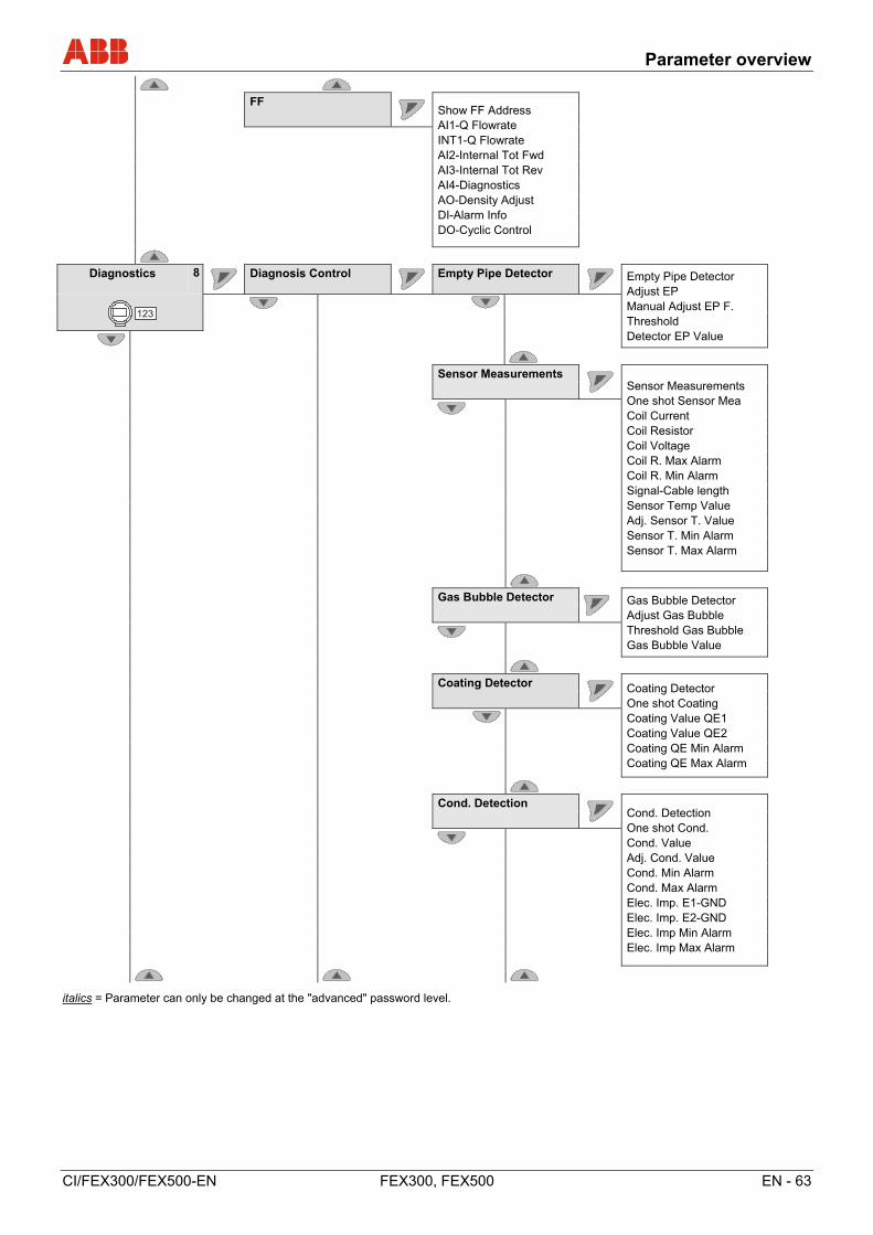
Parameter overview
CI/FEX300/FEX500-EN FEX300, FEX500 EN - 63
FF Show FF Address
AI1-Q Flowrate INT1-Q Flowrate AI2-Internal Tot Fwd AI3-Internal Tot Rev AI4-Diagnostics AO-Density Adjust DI-Alarm Info DO-Cyclic Control
Diagnostics 8
Diagnosis Control
Empty Pipe Detector Empty Pipe Detector
Adjust EP Manual Adjust EP F. Threshold Detector EP Value
Sensor Measurements Sensor Measurements
One shot Sensor Mea Coil Current Coil Resistor Coil Voltage Coil R. Max Alarm Coil R. Min Alarm Signal-Cable length Sensor Temp Value Adj. Sensor T. Value Sensor T. Min Alarm Sensor T. Max Alarm
Gas Bubble Detector
Gas Bubble Detector Adjust Gas Bubble Threshold Gas Bubble Gas Bubble Value
Coating Detector Coating Detector
One shot Coating Coating Value QE1 Coating Value QE2 Coating QE Min Alarm Coating QE Max Alarm
Cond. Detection Cond. Detection
One shot Cond. Cond. Value Adj. Cond. Value Cond. Min Alarm Cond. Max Alarm Elec. Imp. E1-GND Elec. Imp. E2-GND Elec. Imp Min Alarm Elec. Imp Max Alarm
italics = Parameter can only be changed at the "advanced" password level.
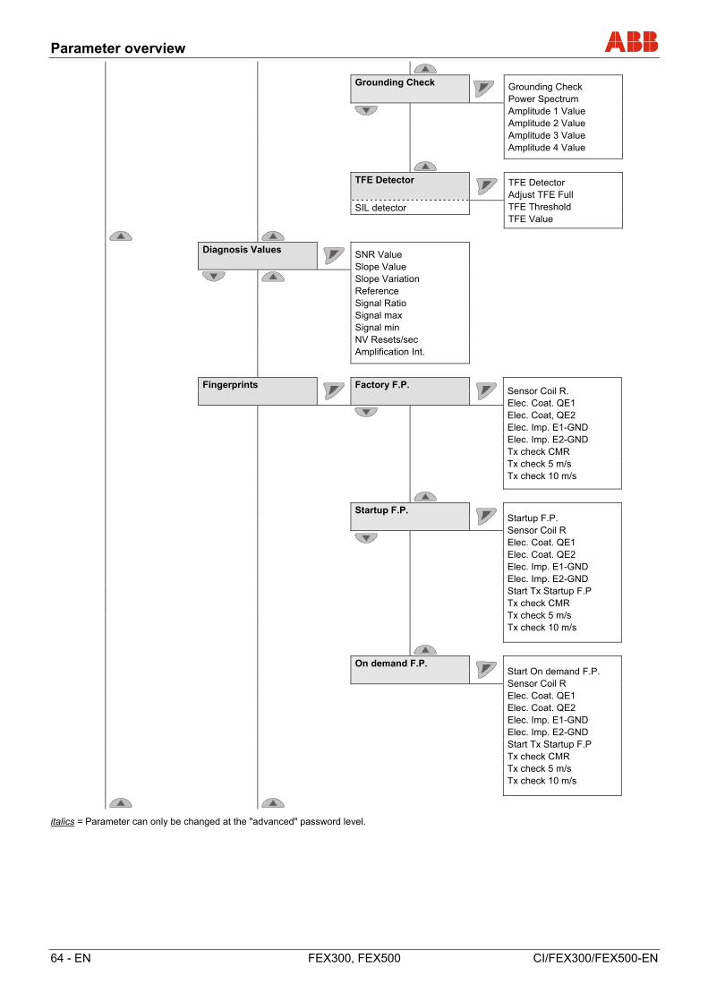
Parameter overview
64 - EN FEX300, FEX500 CI/FEX300/FEX500-EN
Grounding Check
Grounding Check Power Spectrum Amplitude 1 Value Amplitude 2 Value Amplitude 3 Value Amplitude 4 Value
TFE Detector TFE Detector
Adjust TFE Full TFE Threshold TFE Value
SIL detector
Diagnosis Values SNR Value
Slope Value Slope Variation Reference Signal Ratio Signal max Signal min NV Resets/sec Amplification Int.
Fingerprints
Factory F.P. Sensor Coil R.
Elec. Coat. QE1 Elec. Coat, QE2 Elec. Imp. E1-GND Elec. Imp. E2-GND Tx check CMR Tx check 5 m/s Tx check 10 m/s
Startup F.P. Startup F.P.
Sensor Coil R Elec. Coat. QE1 Elec. Coat. QE2 Elec. Imp. E1-GND Elec. Imp. E2-GND Start Tx Startup F.P Tx check CMR Tx check 5 m/s Tx check 10 m/s
On demand F.P. Start On demand F.P.
Sensor Coil R Elec. Coat. QE1 Elec. Coat. QE2 Elec. Imp. E1-GND Elec. Imp. E2-GND Start Tx Startup F.P Tx check CMR Tx check 5 m/s Tx check 10 m/s
italics = Parameter can only be changed at the "advanced" password level.

Parameter overview
CI/FEX300/FEX500-EN FEX300, FEX500 EN - 65
Trend
Conductivity Electrode Coat. QE1 Electrode Coat. QE2 Logtime Interval Trend-Logging
Flowrate Alarm
Max. Flowrate Alarm Min. Flowrate Alarm
Simulation Mode Off, Flow Simulation,
Q [Unit], Q [%], CurrentOut, Pulse on DO1, Pulse on DO2, Logic on DO1, Logic on DO2, HART Freq, Digital input
Output Readings
Current DO1 Frequency DO1 State Digital In State
Totalizer 9
Reset Vol. Totals
Totalizer Fwd Totalizer Rev Totalizer Net All Vol. Totalizer
Batching
Damping Preset Batch Tot. Lag Corr. Mode Lag Corr. Quantity Batch Tot. Total Batch Counter Reset Batch Counter Start/Stop Batching
Edit Vol. Totals
Edit Totalizer Fwd Edit Totalizer Rev Edit Totalizer Net
italics = Parameter can only be changed at the "advanced" password level.
Extended diagnostic functions
66 - EN FEX300, FEX500 CI/FEX300/FEX500-EN
8 Extended diagnostic functions
8.1 General remarks
IMPORTANT (NOTE)
• The extended diagnostic functions are available for ProcessMaster 500 and HygienicMaster 500 only.
• The "Partial Filling Detector" function is not available for HygienicMaster 500.
• When using the extended diagnostic functions the external flowmeter sensor must not be provided with a preamplifier.
• To facilitate initial start-up, the extended diagnostic functions are deactivated (factory default).
• To use the extended diagnostic functions, a "start-up fingerprint" must be created during start-up of the flowmeter.
• Each diagnostic function (e.g. Gas Bubble Detector or Electrode Deposit Detector) can be individually activated. Once activated, the diagnostic function must be calibrated according to the conditions on site and the limit values must be set.
8.1.1 Detection of partial filling
Optionally, a measuring electrode (TFE electrode) is available for detecting a partially filled flowmeter sensor. The alarm for partial filling is output via the programmable digital output.
Conditions for using the function:
• Nominal diameter from DN 50 (2“) with sensor design level B
• Max. signal cable length for version with external transmitter 200 m (656 ft).
• Conductivity of the measuring medium: 20 μS/cm ... 20,000 μS/cm
• The function is only available for ProcessMaster 300 / 500 without explosion protection or with explosion protection for Zone 2 / Div 2.
Additional installation conditions:
• The flowmeter sensor must be installed horizontally with the terminal box pointing upward.
8.1.2 Detection of gas bubbles
Gas bubbles in the fluid are detected by using an adjustable maximum limit value. When this limit value is exceeded, an alarm is tripped via the programmable digital output, depending on the configuration.
Conditions for using the function:
• This function is available in the nominal diameter range 1) of DN 10 … 300 (3/8 “ ... 12 “).
• The signal cable length of the remote transmitter must not exceed a maximum value of 50 m (164 ft) .
• For this function, the conductivity of the measuring medium must be in the range 20 μS/cm ... 20,000 μS/cm.
Additional installation conditions:
• The flowmeter sensor can be installed either horizontally or vertically. Vertical installation is preferred.
1) The specified nominal diameter range is valid for ProcessMaster, only. The nominal diameter range valid for
HygienicMaster is DN 10 … 100 (3/8 “ ... 4 “).
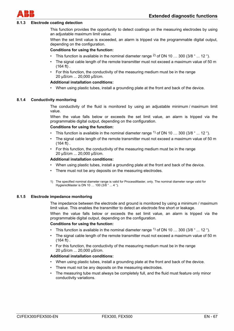
Extended diagnostic functions
CI/FEX300/FEX500-EN FEX300, FEX500 EN - 67
8.1.3 Electrode coating detection
This function provides the opportunity to detect coatings on the measuring electrodes by using an adjustable maximum limit value.
When the set limit value is exceeded, an alarm is tripped via the programmable digital output, depending on the configuration.
Conditions for using the function:
• This function is available in the nominal diameter range 2) of DN 10 … 300 (3/8 “ ... 12 “).
• The signal cable length of the remote transmitter must not exceed a maximum value of 50 m (164 ft) .
• For this function, the conductivity of the measuring medium must be in the range 20 μS/cm ... 20,000 μS/cm.
Additional installation conditions:
• When using plastic tubes, install a grounding plate at the front and back of the device.
8.1.4 Conductivity monitoring
The conductivity of the fluid is monitored by using an adjustable minimum / maximum limit value.
When the value falls below or exceeds the set limit value, an alarm is tripped via the programmable digital output, depending on the configuration.
Conditions for using the function:
• This function is available in the nominal diameter range 1) of DN 10 … 300 (3/8 “ ... 12 “).
• The signal cable length of the remote transmitter must not exceed a maximum value of 50 m (164 ft) .
• For this function, the conductivity of the measuring medium must be in the range 20 μS/cm ... 20,000 μS/cm.
Additional installation conditions:
• When using plastic tubes, install a grounding plate at the front and back of the device.
• There must not be any deposits on the measuring electrodes.
1) The specified nominal diameter range is valid for ProcessMaster, only. The nominal diameter range valid for
HygienicMaster is DN 10 … 100 (3/8 “ ... 4 “).
8.1.5 Electrode impedance monitoring
The impedance between the electrode and ground is monitored by using a minimum / maximum limit value. This enables the transmitter to detect an electrode fine short or leakage.
When the value falls below or exceeds the set limit value, an alarm is tripped via the programmable digital output, depending on the configuration.
Conditions for using the function:
• This function is available in the nominal diameter range 1) of DN 10 … 300 (3/8 “ ... 12 “).
• The signal cable length of the remote transmitter must not exceed a maximum value of 50 m (164 ft) .
• For this function, the conductivity of the measuring medium must be in the range 20 μS/cm ... 20,000 μS/cm.
Additional installation conditions:
• When using plastic tubes, install a grounding plate at the front and back of the device.
• There must not be any deposits on the measuring electrodes.
• The measuring tube must always be completely full, and the fluid must feature only minor conductivity variations.
Extended diagnostic functions
68 - EN FEX300, FEX500 CI/FEX300/FEX500-EN
8.1.6 Sensor measurements
This function includes the monitoring of the sensor temperature and the monitoring of the resistance of the flowmeter sensor's coils.
8.1.6.1 Sensor temperature monitoring
The temperature of the coils in the flowmeter sensor can be monitored by using adjustable minimum / maximum limit values. When a set limit value is exceeded, an alarm is tripped via the programmable digital output, depending on the configuration.
The coil temperature is a factor of the ambient and fluid temperatures. The measurement can, e.g., be used to monitor overtemperature due to the fluid. The coil temperature is measured indirectly via the coil DC resistance.
8.1.6.2 Monitoring of the sensor coil resistance
The coils in the flowmeter sensor can be monitored by using adjustable minimum / maximum limit values for the coil resistance. When a set limit value is exceeded, an alarm is tripped via the programmable digital output, depending on the configuration.
1) The specified nominal diameter range is valid for ProcessMaster, only. The nominal diameter range valid for
HygienicMaster is DN 10 … 100 (3/8 “ ... 4 “).
8.1.7 Trend
The device has an internal memory where the measured value for the electrode deposits and the conductivity are cyclically stored as a data set with an adjustable time (1 min ... 45000 min). A maximum of 12 data sets is stored. When the thirteenth record is stored, the oldest data set is overwritten automatically.
The data sets can be read out or analyzed as a trend using the external diagnostic tool (ScanMaster).
8.1.8 Fingerprint
The “fingerprint” database integrated in the transmitter allows you to compare the values at the time of factory calibration or commissioning with the currently recorded values.
8.1.9 Checking the grounding
This function allows you to check the electrical grounding of the device.
While the check is in progress, no flow measurement can take place.
Conditions for using the function:
• The measuring tube must be completely full.
• No flow must occur in the flowmeter sensor.
Additional installation conditions:
• The flowmeter sensor must not be provided with a preamplifier.
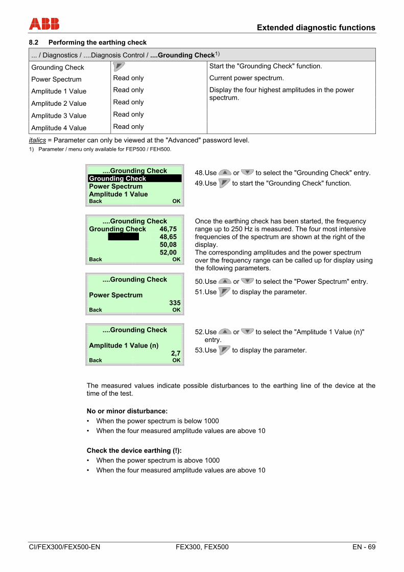
Extended diagnostic functions
CI/FEX300/FEX500-EN FEX300, FEX500 EN - 69
8.2 Performing the earthing check
... / Diagnostics / ....Diagnosis Control / ....Grounding Check1)
Grounding Check Start the "Grounding Check" function.
Power Spectrum Read only Current power spectrum.
Amplitude 1 Value Read only Display the four highest amplitudes in the power spectrum.
Amplitude 2 Value Read only
Amplitude 3 Value Read only
Amplitude 4 Value Read only
italics = Parameter can only be viewed at the "Advanced" password level. 1) Parameter / menu only available for FEP500 / FEH500.
....Grounding Check 48. Use or to select the "Grounding Check" entry.
49. Use to start the "Grounding Check" function.
Grounding Check Power Spectrum Amplitude 1 Value Back OK
....Grounding Check Once the earthing check has been started, the frequency range up to 250 Hz is measured. The four most intensive frequencies of the spectrum are shown at the right of the display. The corresponding amplitudes and the power spectrum over the frequency range can be called up for display using the following parameters.
Grounding Check 46,75 48,65 50,08 52,00 Back OK
....Grounding Check 50. Use or to select the "Power Spectrum" entry.
51. Use to display the parameter.
Power Spectrum
335 Back OK
....Grounding Check 52. Use or to select the "Amplitude 1 Value (n)" entry.
53. Use to display the parameter.
Amplitude 1 Value (n)
2,7 Back OK
The measured values indicate possible disturbances to the earthing line of the device at the time of the test.
No or minor disturbance:
• When the power spectrum is below 1000
• When the four measured amplitude values are above 10
Check the device earthing (!):
• When the power spectrum is above 1000
• When the four measured amplitude values are above 10
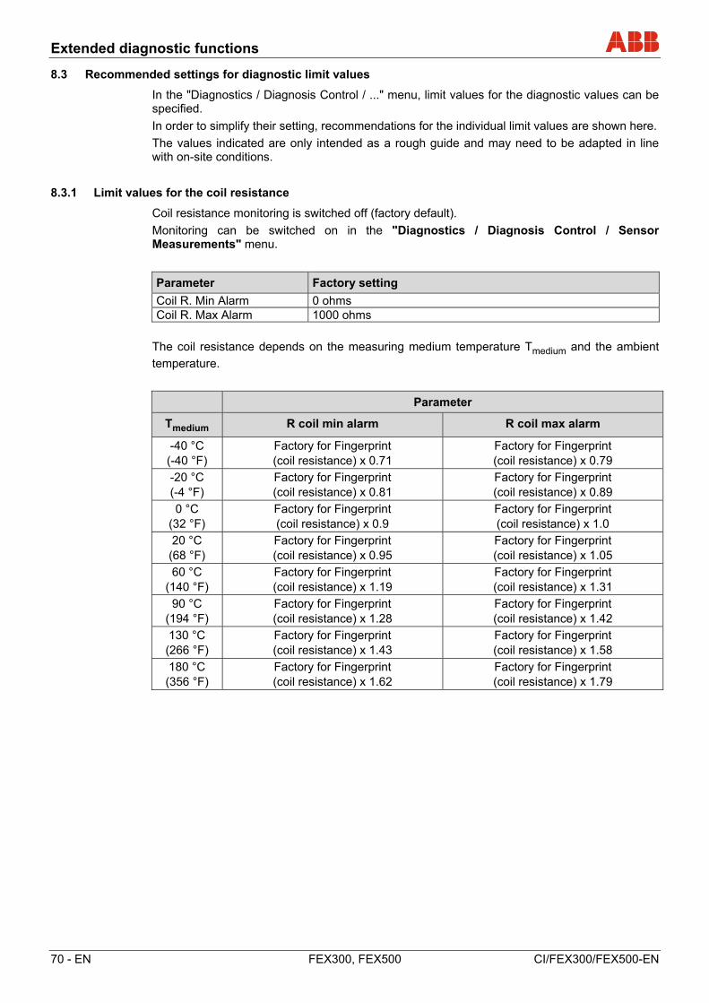
Extended diagnostic functions
70 - EN FEX300, FEX500 CI/FEX300/FEX500-EN
8.3 Recommended settings for diagnostic limit values
In the "Diagnostics / Diagnosis Control / ..." menu, limit values for the diagnostic values can be specified.
In order to simplify their setting, recommendations for the individual limit values are shown here.
The values indicated are only intended as a rough guide and may need to be adapted in line with on-site conditions.
8.3.1 Limit values for the coil resistance
Coil resistance monitoring is switched off (factory default).
Monitoring can be switched on in the "Diagnostics / Diagnosis Control / Sensor Measurements" menu.
Parameter Factory setting
Coil R. Min Alarm 0 ohms Coil R. Max Alarm 1000 ohms
The coil resistance depends on the measuring medium temperature Tmedium and the ambient
temperature.
Parameter
Tmedium R coil min alarm R coil max alarm
-40 °C (-40 °F)
Factory for Fingerprint (coil resistance) x 0.71
Factory for Fingerprint (coil resistance) x 0.79
-20 °C (-4 °F)
Factory for Fingerprint (coil resistance) x 0.81
Factory for Fingerprint (coil resistance) x 0.89
0 °C (32 °F)
Factory for Fingerprint (coil resistance) x 0.9
Factory for Fingerprint (coil resistance) x 1.0
20 °C (68 °F)
Factory for Fingerprint (coil resistance) x 0.95
Factory for Fingerprint (coil resistance) x 1.05
60 °C (140 °F)
Factory for Fingerprint (coil resistance) x 1.19
Factory for Fingerprint (coil resistance) x 1.31
90 °C (194 °F)
Factory for Fingerprint (coil resistance) x 1.28
Factory for Fingerprint (coil resistance) x 1.42
130 °C (266 °F)
Factory for Fingerprint (coil resistance) x 1.43
Factory for Fingerprint (coil resistance) x 1.58
180 °C (356 °F)
Factory for Fingerprint (coil resistance) x 1.62
Factory for Fingerprint (coil resistance) x 1.79
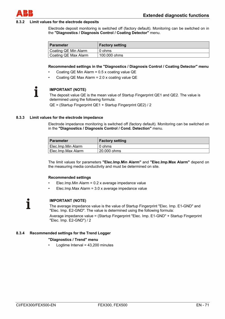
Extended diagnostic functions
CI/FEX300/FEX500-EN FEX300, FEX500 EN - 71
8.3.2 Limit values for the electrode deposits
Electrode deposit monitoring is switched off (factory default). Monitoring can be switched on in the "Diagnostics / Diagnosis Control / Coating Detector" menu.
Parameter Factory setting
Coating QE Min Alarm 0 ohms Coating QE Max Alarm 100.000 ohms
Recommended settings in the "Diagnostics / Diagnosis Control / Coating Detector" menu
• Coating QE Min Alarm = 0.5 x coating value QE
• Coating QE Max Alarm = 2.0 x coating value QE
IMPORTANT (NOTE)
The deposit value QE is the mean value of Startup Fingerprint QE1 and QE2. The value is determined using the following formula:
QE = (Startup Fingerprint QE1 + Startup Fingerprint QE2) / 2
8.3.3 Limit values for the electrode impedance
Electrode impedance monitoring is switched off (factory default). Monitoring can be switched on in the "Diagnostics / Diagnosis Control / Cond. Detection" menu.
Parameter Factory setting
Elec.Imp.Min Alarm 0 ohms Elec.Imp.Max Alarm 20.000 ohms
The limit values for parameters "Elec.Imp.Min Alarm" and "Elec.Imp.Max Alarm" depend on the measuring media conductivity and must be determined on site.
Recommended settings
• Elec.Imp.Min Alarm = 0.2 x average impedance value
• Elec.Imp.Max Alarm = 3.0 x average impedance value
IMPORTANT (NOTE)
The average impedance value is the value of Startup Fingerprint "Elec. Imp. E1-GND" and "Elec. Imp. E2-GND". The value is determined using the following formula:
Average impedance value = (Startup Fingerprint "Elec. Imp. E1-GND" + Startup Fingerprint "Elec. Imp. E2-GND") / 2
8.3.4 Recommended settings for the Trend Logger
"Diagnostics / Trend" menu
• Logtime Interval = 43,200 minutes

Appendix
72 - EN FEX300, FEX500 CI/FEX300/FEX500-EN
9 Appendix
IMPORTANT (NOTE)
All documentation, declarations of conformity and certificates are available in ABB's download area.
www.abb.com/flow
IMPORTANT (NOTE)
This is a class A device (industrial sector). This device can cause radio interferences in residential areas. In this case, the operator may be required to take appropriate measures to remedy the fault.


A
ABB has Sales & Customer Support expertise in over 100 countries worldwide.
www.abb.com/flow
The Company’s policy is one of continuous product improvement and the right is reserved to modify the
information contained herein without notice.
Printed in the Fed. Rep. of Germany (02.2018)
© ABB 2018
C
I/FE
X30
0/F
EX
500-
EN
R
ev. G
3KXF231300R4401
ABB Limited
Measurement & Analytics
Howard Road, St. Neots
Cambridgeshire, PE19 8EU
UK
Tel: +44 (0) 870 600 6122
Fax: +44 (0)1480 213 339
Mail: [email protected]
ABB Inc.
Measurement & Analytics
125 E. County Line Road
Warminster, PA 18974
USA
Tel: +1 215 674 6000
Fax: +1 215 674 7183
ABB Automation Products GmbH
Measurement & Analytics
Dransfelder Str. 2
37079 Goettingen
Germany
Tel: +49 551 905-0
Fax: +49 551 905-777
Mail: [email protected]
ABB Engineering (Shanghai) Ltd. Measurement & Analytics
No. 4528, Kangxin Highway, Pudong New District
Shanghai, 201319,
P.R. China
Tel: +86(0) 21 6105 6666
Fax: +86(0) 21 6105 6677
Mail: [email protected]


![Electromagnetic flowmeter ProcessMaster FEP630 ... · II 2 (1) G Ex db eb ib mb [ia Ga] IIC T6 T1 Gb II 2 (1) D Ex tb [ia Da] IIIC T80°C T medium Db DN3-100: II 2 (1) G Ex db eb](https://img.pdfslide.us/doc/110x75/5f0fde527e708231d4464930/electromagnetic-flowmeter-processmaster-fep630-ii-2-1-g-ex-db-eb-ib-mb-ia.jpg)


![Interface Description Electromagnetic Flowmeter COM/FEX300 ... · The interface conforms to Profile 3.01 (PROFIBUS standard, EN 50170, DIN 19245 [PRO91]). PROFIBUS PA ID No.: 0x3430](https://img.pdfslide.us/doc/110x75/5f9540f36c1a5c7b923a7021/interface-description-electromagnetic-flowmeter-comfex300-the-interface-conforms.jpg)