Embed Size (px)
Citation preview

Processing Guide for DuPont Luxprint® Electroluminescent Inks
(Revised May 2012)
Introduction Recent major advances in materials and electronics technology, as well as new demands on lighting technology from the marketplace have provided the opportunity for a fundamental shift in the role of electroluminescent (EL) technology. For that reason, DuPont has developed a system of conducting, insulating and luminescent inks suitable for manufacturing printed lamps, enabling companies skilled in screen-printing of electronic circuitry to easily manufacture flexible EL lamps. The main EL characteristics are: • Uniform surface illumination of complex shapes • Thin, flexible and light weight • Low power consumption • Very low heat generation • Vibration and impact resistant The EL lamp is essentially a capacitor structure with an inorganic phosphor (zinc sulphide compound) sandwiched between the electrodes. Application of an AC voltage across the electrodes generates a changing electric field within the phosphor particles causing them to emit light. For most EL lamps, an inverter is used as a power source. An inverter is a DC-AC converter, which typically generates 60-115V AC and frequencies in the region of 50-1000 Hz. For signage applications much higher frequencies can be used to increase lamp brightness. Light output gradually decays with time, as the luminescent efficiency decreases. The presence of moisture accelerates this decline. The phosphors used in DuPont Luxprint® EL inks are micro-encapsulated to hinder the penetration of moisture and thus to prolong the useful life of the lamps. The polymer binders in the DuPont Luxprint® EL pastes have been selected to provide a barrier, which further protects against moisture-related aging phenomena. Higher voltages and frequencies, as well as elevated temperatures during operation, will reduce the lifetime of the lamps. Operation at lower temperatures, voltages and frequencies should be encouraged, with 80 - 120 V AC and 400 Hz being typical conditions. The following provides descriptions of process steps and materials which have proven important in successful implementations of the DuPont Luxprint® EL system to date. The recommendations and descriptions found herein are based upon experience gained during the development of these inks. Process optimization will be necessary to conform to the particular design of the EL lamp and processing equipment used. These guidelines may not prove applicable for new or different applications, and the user must carefully evaluate their usefulness in each case. The DuPont Luxprint® materials system provides the inks needed to make EL lamps by screen printing. Other materials, such as the transparent sputtered ITO (Indium Tin Oxide) polyester substrate, as well as the power supply, must be obtained from other sources. Each of these inks is designed to be used without further dilution in a screen-printing process. The products are mutually compatible, and provide excellent adhesion to ITO, which is typically utilized as a thin conductive coating on polyester, or other film base.

EL Application - Advertising (POS) An eye-catching series of Sequenced lighting patterns
81XX Type System: Higher brightness/moisture resistance than the 71XXJ System and designed for more demanding applications.
Table 2 Product Number Phosphors
8150B or 8150L White Phosphor 8152B or 8152L Blue-Green Phosphor 8154L Yellow-Green Phosphor
Dielectrics
8153 High K Dielectric Insulator
Conductors Build Sequence 1
8144 Rear Electrode, Carbon Conductor (with UV Encapsulants) 7152 Rear Electrode, Carbon Conductor (with 7165 Encapsulant) 7162 Front Electrode, ATO (Antimony Tin Oxide) Translucent Conductor 9145 Rear Electrode, Silver Conductor (also for bus-bar and termination)
Conductors Build Sequence 2
7102 Rear Electrode, Carbon Conductor (if overprinting 5000 Ag) 7105 Rear Electrode, Carbon Conductor 5000 Rear Electrode, Silver Conductor (also for bus-bar and termination) 7164 Front Electrode, ATO (Antimony Tin Oxide) Translucent Conductor
Protective Encapsulant Build Sequence 1
5018A Clear UV Cure Ink 5018G Green UV Cure Ink 5018 Blue UV Cure Ink 7165 Clear Solvent Ink (single print only)

EL Application – Advertising (POS) – Glowing Eyes Sequence

DESIGN NOTES The printed EL lamp consists of a sandwich structure containing an appropriate substrate, a rear electrode, an insulating layer, the phosphor layer, a transparent or translucent front electrode and a protective layer (see schematic diagram). The lamp may be terminated by a silver conductor, and crimped connectors (or other means) to allow connection to the power source. Care must be taken in providing a connection with good integrity. For outdoor use additional moisture protection and UV protection are essential. There are various lamp builds possible, with the two most common constructions described below. Build Sequence 1 Uses a transparent base substrate. Polyester film, sputtered with ITO or coated with a conducting polymer, can be used as the front electrode. Alternatively, a screen printed conducting translucent ink can be used on a clear base substrate. The build sequence printed on top is simply phosphor, then either: (a) 2 prints of dielectric (< 25 microns total dried thickness), which will give a brighter lamp but
may reduce the yield and reliability, or (b) 3 prints of dielectric (> 25 microns total dried thickness) (preferred) for optimum yield and
reliability, Followed by the rear electrode.
AC
Light
Protective encapsulant
Dielectric
Rear electrode
Phosphor
ITO film or translucentconductive ink on polyester
Build Sequence 1

A printed silver bus-bar along the perimeter of the lamp should be used for large areas in order to provide more even illumination of the lamp. For the rear electrode, a silver or carbon conductor is generally used. For larger lamp areas, carbon is not suitable alone, unless it is overprinted with a silver grid, as the carbon resistance is too high. The final product should be laminated to provide protection from moisture and electrical isolation, for safety reasons. Alternatively, a protective layer can be screen-printed using UV cure ink or solvent ink. (See Diagram Build Sequence 1). 5018/A/G screen printable UV cure inks or 7165 solvent ink can be used as an encapsulant in order to provide electrical insulation and extra protection against humid environments. The UV encapsulants do not adhere well to ITO-sputtered film, so it is recommended to limit the print area of the 5018/A/G to that of the underlying dielectric. 7165 adheres well to ITO film but can only be used in a single print. In more complex EL lamp constructions, 2 layers of 5018/A/G can be used as an effective insulator where conductor crossovers are present. Printing local crossovers may cause cracking over the dielectric, and it is therefore advisable to print the first UV encapsulant layer over the whole lamp area. A thick, single print of 7165 solvent encapsulant can be used as an option. When using a carbon rear conductor, 7165 should be used over 7152 instead of 8144. Build Sequence 2 Various substrate types could potentially be used. Using a translucent conductive ink, it is possible to use other base substrates as long as these are compatible with the solvent and resin system and are capable of withstanding the elevated temperature drying conditions.
The build sequence here is reversed with the rear electrode printed first. Again, as in Build Sequence 1, a silver bus-bar is recommended. A silver underprint should be applied if a carbon
AC
Light
Translucent ConductorPhosphor
Dielectric
Clear Encapsulant
Rear electrode on acompatible substrate
Build Sequence 2
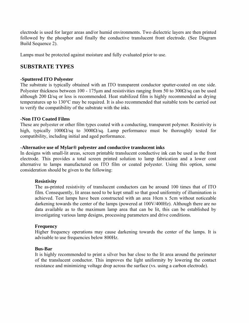
electrode is used for larger areas and/or humid environments. Two dielectric layers are then printed followed by the phosphor and finally the conductive translucent front electrode. (See Diagram Build Sequence 2). Lamps must be protected against moisture and fully evaluated prior to use. SUBSTRATE TYPES -Sputtered ITO Polyester The substrate is typically obtained with an ITO transparent conductor sputter-coated on one side. Polyester thickness between 100 - 175µm and resistivities ranging from 50 to 30/sq can be used although 200 Ω/sq or less is recommended. Heat stabilized film is highly recommended as drying temperatures up to 130°C may be required. It is also recommended that suitable tests be carried out to verify the compatibility of the substrate with the inks. -Non ITO Coated Films These are polyester or other film types coated with a conducting, transparent polymer. Resistivity is high, typically 100/sq to 300/sq. Lamp performance must be thoroughly tested for compatibility, including initial and aged performance. -Alternative use of Mylar® polyester and conductive translucent inks In designs with small-lit areas, screen printable translucent conductive ink can be used as the front electrode. This provides a total screen printed solution to lamp fabrication and a lower cost alternative to lamps manufactured on ITO film or coated polyester. Using this option, some consideration should be given to the following:
Resistivity The as-printed resistivity of translucent conductors can be around 100 times that of ITO film. Consequently, lit areas need to be kept small so that good uniformity of illumination is achieved. Test lamps have been constructed with an area 10cm x 5cm without noticeable darkening towards the center of the lamps (powered at 100V/400Hz). Although there are no data available as to the maximum lamp area that can be lit, this can be established by investigating various lamp designs, processing parameters and drive conditions. Frequency Higher frequency operations may cause darkening towards the center of the lamps. It is advisable to use frequencies below 800Hz. Bus-Bar It is highly recommended to print a silver bus bar close to the lit area around the perimeter of the translucent conductor. This improves the light uniformity by lowering the contact resistance and minimizing voltage drop across the surface (vs. using a carbon electrode).
Paste Selection Depending on the build sequence to be used, paste selection is critical to the performance of the lamp. a) Build Sequence 1 - It is advisable to use a heat stabilized, print treated polyester. - Translucent conductor 7162 is printed first. This uses ATO conductive particles, which have a
neutral gray color. - 9145 silver bus bar printed next (optional if carbon rear electrode). - Phosphor is printed next, with a choice of output color. - The phosphor is followed by 2-3 layers of dielectric. - 9145 Silver or 8144 Carbon is printed onto the dielectric. These compositions are compatible
and their use is highly recommended. It has been found that various alternative conductors have adversely impacted the short/long term lamp performance.
- Lamp encapsulation with UV cure ink 5018/A/G or solvent based 7165 has been found to
provide additional protection.

Lamp Build Sequence 1 DuPont Electroluminescent Material Recommendation
BASE/ PRINT 1 PRINT 2 PRINTS 3 & 4 PRINT 5 PRINT 6 Front Electrode on Base Phosphor 2 – 3 Dielectric Layer Rear Electrode & Protective ITO Polyester Film 8150B or L White 8153 High K Front Bus bar Back Layer 7162 ATO on Polyester 8152B or L Blue-Green 8144 Carbon 5018/A/G UV Cure 9145 Silver bus bar 8154L Yellow-Green 7152 Carbon 7165 Solvent Ink
9145 Silver

b) Build Sequence 2 - With polyester, it is advisable to use a heat stabilized, print treated surface. Other substrates can
be used, e.g. FR4 printed circuit board, providing they are compatible with the solvent and resin system and can withstand drying at 130°C.
- The rear electrode and bus bar are printed first. It is recommended to use 5000 Silver for the bus
bar, and 5000 Silver or 7102 / 7105 Carbon as the rear electrode. - This is followed by 8153 dielectric over the rear electrode. - The next print is phosphor. - Finally, the translucent conductor 7164 is printed over the phosphor ensuring there is good
contact to the silver bus bar.
El Application – Advertising. Multi-color sequence design.


Lamp Build Sequence 2 DuPont Electroluminescent Material Recommendation
BASE PRINT 1 PRINTS 2 & 3 PRINT 4 PRINT 5 Base Substrate Rear Electrode & 2 - 3 Dielectric Phosphor Translucent Front Bus bar Layer Front Conductor Various e. g. 5000 Silver 8153 High K 8150B or L White 7164 ATO polyester, FR4 7102 Carbon 8152B or L Blue-Green Printed Circuit 7105 Carbon 8154L Yellow-Green Board

PROCESSING Storage Containers of DuPont Luxprint® EL inks may be stored in a clean, stable environment at room temperature (25°C) with their lids tightly sealed. Storage in freezers (temperature <0°C) is not recommended, as this could cause irreversible changes in the material. Jar rolling is not recommended for the Carbon, Silver, and Dielectric inks, as this could change the rheology of these materials. The Phosphor inks and Translucent conductors settle, so gentle jar rolling at 2 –5 rpm is recommended before use. Handling DuPont Luxprint® EL inks should be thoroughly mixed before use. This is best achieved by slow, gentle hand stirring with a clean, burr-free spatula (flexible plastic) for 1-2 minutes. Particular care should be given to the Phosphor inks, as the micro-encapsulation may be damaged by vigorous agitation. Printing should be carried out in a clean, well-ventilated area. Additional information on requirements for printing areas is available in DuPont Technical Guide EUT 7.3 “Screen Printing Rooms” which is available on request. Although DuPont Luxprint® EL inks are optimized for screen printing and thinning is not normally required, the appropriate DuPont Thinner may be used sparingly for slight adjustments to viscosity or to replace evaporation losses. However, the use of too much thinner or the use of a non-recommended thinner may affect the rheological behavior of the materials and their printing characteristics. Printing Optimum printing characteristics of DuPont Luxprint® EL inks are generally achieved in the temperature range 20 - 23°C. It is therefore important that the materials, in their container, are at this temperature prior to commencement of printing. Screens Screen selection is very important to the overall performance of the lamps. Table 3 has a list of suggested polyester screens that may be used. Further optimization may be necessary de-pending on printers and processing conditions used. Drying Drying at 130°C for 15 minutes in a well-ventilated box oven has been found to be very effective for these materials. This should be used as a starting point to find the equivalent drying conditions on the production line. Successful trials have been run on a reel-to-reel set-up. This has been found to give more efficient drying and so shorter drying times (around 2 minutes) can be used. Test Strips During construction of the lamps, the use of test strips at the edge of the prints is highly recommended. These will enable batch to batch consistency checks as well as on-going quality controls. These areas can also provide vital processing information if fault finding is necessary.

Table 3 Print Screen Selector for 81xx Systems
Product number Polyester mesh (threads/inch)
Thickness (µm)
Coverage (cm²/g)
Phosphor 8150B or L White 8152B or L Blue-Green 8154L Yellow-Green
156
30 - 40
100 - 150
Dielectric 8153
156 – 195
25 – 30 (3 layers) 18 – 22 (2 layers)
50 – 80 (3 layers) 70 – 100 (2 layers)
Conductors Build Sequence 1 8144 Carbon 7152 Carbon 9145 Silver 7162 ATO
195
6 – 10 6 – 10 6 – 10 8 – 12
350 – 400 350 – 400 300 – 350 300 – 350
Conductors Build Sequence 2 7102 Carbon 7105 Carbon 5000 Silver 7164 ATO
195
6 – 10 6 – 10 6 – 10 6 – 10 8 – 12
350 – 400 350 – 400 300 – 350 300 – 350 300 – 350
Protective Encapsulants 5018/A/G UV Cure 7165 Solvent Ink
195 156
25 – 35 (2 layers) 6 – 10 (1 layer)
200 – 300 (2 layers) 350 – 400
All values reported here are results of experiments in our laboratories intended to illustrate product performance potential with a given experimental design. They are not intended to represent the product’s specifications, details of that are available upon demand.

*8150B under development
CIE 1931 Chromaticity Diagram
Yellow/Green
Blue/Green
Pink White
Approximate colour coordinates EL Luxprint Colours
*8150B under development
EL Product Summary & Selector Guide
Composition Description Comments Screen Selector Guide
High Brightness Long Life Screen Mesh Thickness CoverageAutomotive Suggested (typical) (approx)
Grade (threads/inch) (µm) cm2/g
Phosphors yellow-green 8154B* 8154L 156 30-40 100-150blue-green 8152B 8152L 156 30-40 100-150white Pink off. 8150B 8150L 156 30-40
156 30-40
156 30-40 100-150Vehicle
Dielectric Insulator High K 156-195 18-30 50-100
Conductors - Build Sequence 1Ag 195 8 300-350C Also Ag migration barrier 195 10 350-400Translucent Low cost non-ITO 195 10 300-350
- Build Sequence 2Ag Only for build seq 2 195 6 300-350C Only for build seq 2 195 10 350-400Translucent Low cost non-ITO 195 10 300-350
Protection Build seq 1 Solvent/ UV Cure 195 6/17 350Build seq 2 For small areas 350
Complex Build LampsX-Overs Dielectric Low K 195 25-30 >3505018/A/G
8155
8153
5018A
Product Numbers
71027164
7165/5018
914581447162
5000
*8154B under development
100-150100-150
(2 layers)

Accelerated Half Life - 60C/90%
0
10
20
30
40
50
60
70
80
90
100
0 50 100 150 200 250 300 350
Time (Hrs)
Rel
ativ
e B
right
ness
(%)
8152L
8152B
7151J
Brightness - 100V/400Hz
0
10
20
30
40
50
60
70
80
90
100
7151J 8152L 8152B
Blue/Green
Brig
htne
ss (C
d/m
2)
Half Life - Room Temperature
0
10
20
30
40
50
60
70
80
90
100
0 400 800 1200 1600 2000 2400 2800 3200
Time (Hrs)
Rel
ativ
e B
right
ness
(%)
8152L
8152B
7151J
Blue/Green 7151J vs 8152L & 8152B
*NOTE 7151J IS NO LONGER COMMERCIALLY AVAILABLE. PERFORMANCE DATA ARE FOR COMPARISON PURPOSE ONLY.

Accelerated Half Life - 60C/90%
0
10
20
30
40
50
60
70
80
90
100
0 50 100 150 200 250 300 350
Time (Hrs)
Rel
ativ
e B
right
ness
(%)
8150L
8150B7138J
Brightness - 100V/400Hz
0
10
20
30
40
50
60
70
80
7138J 8150L 8150B
Blue/Green
Brig
htne
ss (C
d/m
2)
Half Life - Room Temperature
0
10
20
30
40
50
60
70
80
90
100
0 400 800 1200 1600 2000 2400 2800 3200
Time (Hrs)
Rel
ativ
e B
right
ness
(%)
8150L8150B7138J
Pink/White 7138J vs 8150L & 8150B
*NOTE 7138J IS NO LONGER COMMERCIALLY AVAILABLE. PERFORMANCE DATA ARE FOR COMPARISON PURPOSE ONLY.

Accelerated Half Life - 60C/90%
0
10
20
30
40
50
60
70
80
90
100
0 50 100 150 200 250 300 350
Time (Hrs)
Rel
ativ
e B
right
ness
(%)
8154L
8154B7154J
Brightness - 100V/400Hz
0
10
20
30
40
50
60
70
80
90
100
7154J 8154L 8154B
Blue/Green
Brig
htne
ss (C
d/m
2)
Half Life - Room Temperature
0
10
20
30
40
50
60
70
80
90
100
0 400 800 1200 1600 2000 2400 2800 3200
Time (Hrs)
Rel
ativ
e B
right
ness
(%)
8154L
8154B
7154J
Yellow/Green 7154J vs 8154L & 8154B
*NOTE 7154J IS NO LONGER COMMERCIALLY AVAILABLE. PERFORMANCE DATA ARE FOR COMPARISON PURPOSE ONLY.

S u m m a ry o f T y p ic a l P h o s p h o r P e r fo rm a n c e D a ta - C o m p a r is o n T a b le
C a p a c it a n c e Im p e d a n c e P h a s e P o w e r E f f ic ie n c yC o lo u r B r ig h tn e s s R /T e m p 6 0 C /9 0 % S e r ie s P a r ra le l A n g le D ra w
C Z R s R pC o m p o s it io n C d /m 2 x y h rs h rs n F /c m 2
K o h m /c m2
K o h m /c m2
M o h m /c m2
- d e g m W /cm 2 L m /W
7 1 5 1 J b lu e /g re e n 4 6 .8 0 .1 7 1 0 .3 5 0 7 0 0 7 0 0 .6 1 6 4 0 1 1 0 3 .6 7 9 2 .7 5 .0
8 1 5 2 L b lu e /g re e n 5 4 .9 0 .1 7 1 0 .3 7 9 2 8 0 0 3 1 0 0 .6 6 5 8 0 1 1 0 3 .0 7 9 3 .2 5 .0
8 1 5 2 B b lu e /g re e n 8 9 .4 0 .1 6 5 0 .3 9 5 1 0 0 0 1 3 0 0 .6 8 5 8 0 1 1 0 3 .0 7 9 3 .2 8 .4
7 1 5 4 J ye l/g re e n 5 7 .5 0 .1 7 6 0 .4 2 2 1 6 0 0 1 1 0 0 .6 1 6 4 0 1 1 0 3 .6 7 9 2 .7 5 .9
8 1 5 4 L ye l/g re e n 6 3 .5 0 .1 7 7 0 .4 2 9 3 0 0 0 3 1 0 0 .6 6 5 8 0 1 1 0 3 .0 7 9 3 .2 5 .6
8 1 5 4 B ye l/g re e n 8 7 .5 0 .1 8 2 0 .4 6 3 1 3 0 0 1 6 0 0 .6 8 5 8 0 1 1 0 3 .0 7 9 3 .2 7 .8
7 1 3 8 J p in k /w h ite 3 3 .7 0 .2 9 5 0 .3 3 7 8 0 0 9 0 0 .6 1 6 4 0 1 1 0 3 .6 7 9 2 .7 3 .8
8 1 5 0 L p in k /w h ite 3 9 .4 0 .3 0 1 0 .3 5 3 2 8 0 0 3 3 0 0 .6 6 5 8 0 1 1 0 3 .0 7 9 3 .2 3 .9
8 1 5 0 B p in k /w h ite 6 7 .2 0 .2 9 5 0 .3 6 7 1 1 0 0 1 2 0 0 .6 8 5 8 0 1 1 0 3 .0 7 9 3 .2 6 .5
8 1 4 0 w h ite /w h ite 2 2 .6 0 .3 0 7 0 .3 6 0 1 7 0 0 3 0 0 0 .6 6 5 8 0 1 1 0 3 .0 7 9 3 .2 1 .9
8 1 6 0 b lu e 3 9 .6 0 .1 5 9 0 .2 0 5 6 0 0 7 0 0 .6 2 6 2 0 1 4 0 2 .7 7 7 3 .6 3 .2
7 1 8 2 O ra ng e 1 3 0 .5 4 0 0 .4 5 0 3 5 0 0 3 0 0 0 .6 2 6 2 0 1 0 0 3 .7 7 9 2 .7 1 .6
E le c tr ic a l P ro p e r t ie s (1 m e a s u re m e n t se t @ 1 0 0 V /4 0 0 H z )R e s is ta n c e
C o lo u r c o o rdH a lf L if e
For more information on DuPont Luxprint® or other DuPont Microcircuit Materials products, please contact your local representative:
Americas
DuPont Microcircuit Materials
14 T.W. Alexander Drive
Research Triangle Park, NC 27709
Tel.: 800-284-3382
Europe
Du Pont (U.K.) Limited
Coldharbour Lane
Bristol BS16 1QD
U.K.
Tel.: 44-117-931-3191
DuPont Kabushiki Kaisha
Sanno Park Tower, 11-1
Nagata-cho 2-chome
Chiyoda-ku, Tokyo 100-611
Japan
Tel.: 81-3-5521-8650
DuPont Taiwan Ltd
45, Hsing-Pont Road,
Taoyuan, Taiwan 330
Tel.: 886-3-377-3616
DuPont China Holding Co. Ltd
Bldg 11, 399 Keyuan Rd., Zhangji Hi-Tech Park,
Pudong New District, Shanghai 201203, China
Tel.: 86-21-6386-6366 ext.2202
DuPont Korea Inc.
3~5th Floor, Asia tower #726,
Yeoksam-dong, Gangnam-gu
Seoul 135-719, Korea
Tel.: 82-10-6385-5399
Du Pont Company (Singapore) Pte Ltd
1 HarbourFront Place, #11-01
HarbourFrong Tower One,
Singapore 098633
Tel.: 65-6586-3022
http://mcm.dupont.com
*NOTE 7151J, 7154J AND 7138J ARE NO LONGER COMMERCIALLY AVAILABLE. PERFORMANCE DATA ARE FOR COMPARISON PURPOSE ONLY.