Embed Size (px)
Citation preview
PROCESSING AND PROPERTIES OF A DUAL PHASE PM STEEL
Chris Schade & Tom Murphy Hoeganaes Corporation Cinnaminson, NJ 08077
Alan Lawley & Roger Doherty
Drexel University Philadelphia, PA 19104
ABSTRACT The development of materials utilizing lower alloy contents is essential to the cost competiveness of powder metallurgy (PM). Alloys systems that contain low levels of alloying elements such as nickel and molybdenum, yet provide adequate strength and ductility, can be developed utilizing strengthening mechanisms such as precipitation hardening and microalloying. This study details the processing, microstructures and properties of a low alloy PM steel in which these alloying techniques are used with the ultimate goal of producing a dual-phase microstructure coupled with precipitation hardening. Processing of these alloys is detailed and attendant microstructures and mechanical properties compared with those of conventional PM steels.
INTRODUCTION There is a continuing need to develop PM steels with higher strength, while maintaining adequate levels of ductility and impact toughness. Although advances have been made in high density processing, such as warm compaction, improved lubrication, and high density powders, there remains a need to develop alloy systems which, in themselves, improve the competitiveness of PM in relation to wrought alloys. In these systems it is desirable to use as little alloy content as possible. High-strength low alloy (HSLA) steels or microalloyed steels, generally give superior mechanical properties utilizing low alloy levels coupled with thermo-mechanical processing. Dual-phase steels are considered a subclass of HSLA steels and exhibit a microstructure consisting of a hard phase (primarily martensite and/or bainite) in a matrix of ferrite. Due to their composite microstructures, dual phase steels exhibit excellent mechanical properties with tensile strength generally dependent primarily on the volume fraction of martensite. The authors have recently developed a dual phase precipitation hardened stainless steel in which this
combination of strengthening mechanisms has led to a material with improved strength and ductility1. To explore whether or not this technique can be applied to conventional low alloy PM steels a development study was undertaken in which the precipitation of copper was studied in iron-copper systems typically used in low alloy PM steels. Because the precipitation temperature for copper is relatively high (450 to 600 oC (850 to 1100 oF)), the addition of alloying elements which tend to stabilize the carbides was examined. Since copper stabilizes austenite (which transforms to martensite on cooling), elements that stabilize ferrite such as chromium, molybdenum and silicon were studied with the expectation that a dual phase microstructure could be developed. In addition, microalloying elements such as niobium, titanium and vanadium were evaluated in an attempt to co-precipitate carbides and nitrides along with the copper. This may allow for the use of lower levels of alloying elements, including carbon. This approach is attractive to the PM industry since low carbon contents yield higher green and sintered densities. It is also possible that the loss of strength due to the lower carbon level can be offset by precipitation. Precipitation Hardening Strengthening, as a result of precipitation hardening, takes place in three steps:2
(1) Solution treatment, in which the alloy is heated to a relatively high temperature, allows any precipitates or alloying elements to form a supersaturated solid solution. Typical solution treatment temperatures for steels are in the range of 982 oC to 1066 oC (1800 oF to 1950 oF).
(2) Quenching, in which the solution treated alloy is cooled to create a supersaturated solid solution. The cooling can be achieved using air, water or oil. In general, the faster the cooling rate the finer the grain size which can lead to improved mechanical properties. Regardless of the method of cooling, the cooling rate must be sufficiently rapid to create a supersaturated solid solution.
(3) Precipitation or age hardening, in which the quenched alloy is heated to an intermediate temperature or held at room temperature for a period of time. During aging, the supersaturated solid solution decomposes and the alloying elements form small precipitate clusters. The precipitates hinder the movement of dislocations and consequently the metal resists deformation and becomes harder and stronger.
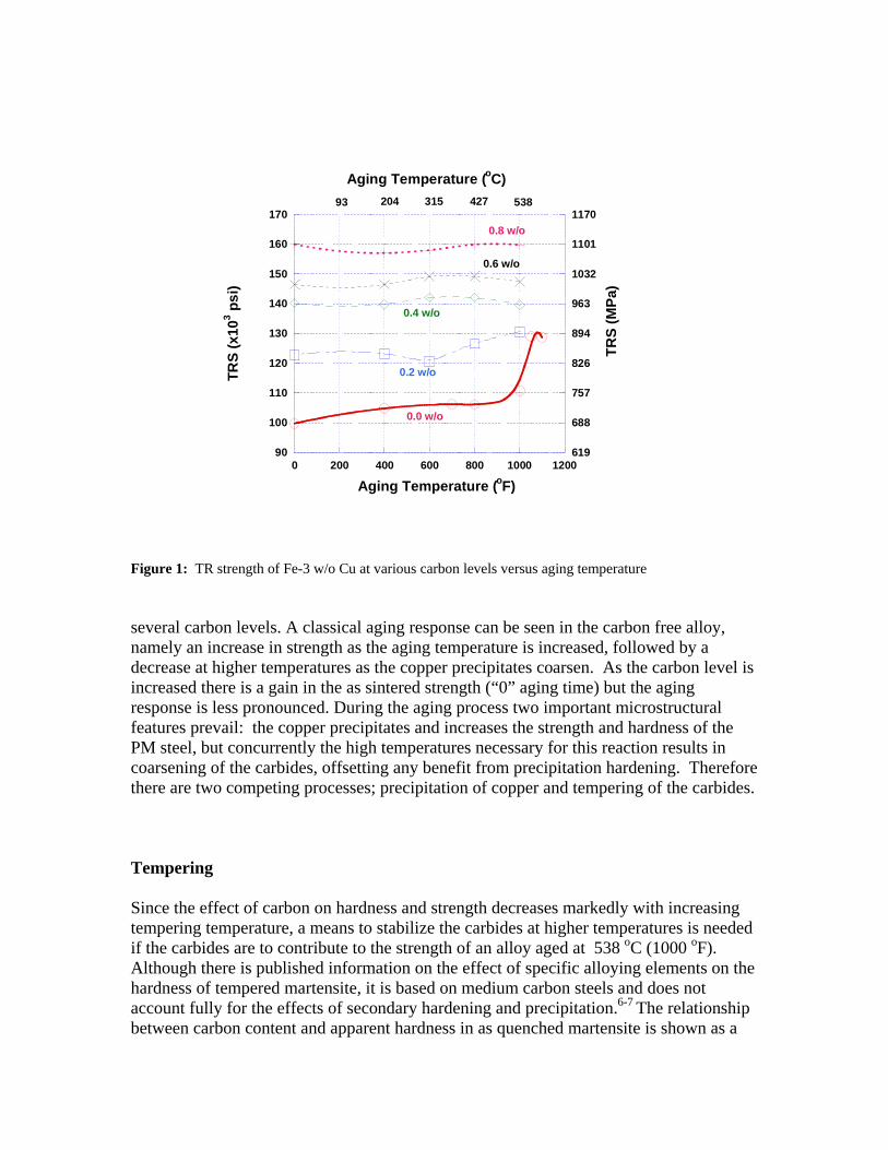
The age hardening response of copper-bearing high strength low alloy and multiphase steels has been shown to occur at temperatures ranging from 450 to 600 oC (850 to 1100 oF) and has been shown to increase strength and hardness by 15 to 20 percent 3-5. Since there is widespread use of the iron-copper system in PM components, a study of aging in the iron-copper system to enhance strength is a logical step. However there are a number of challenges to this objective, as illustrated by Figure 1 which shows the change in transverse rupture strength with aging temperature for
90
100
110
120
130
140
150
160
170
0 200 400 600 800 1000 1200619
688
757
826
894
963
1032
1101
1170
TRS
(x10
3 psi
)
Aging Temperature (oF)
93 204 315 427 538
Aging Temperature (oC)
TRS
(MPa
)
0.0 w/o
0.2 w/o
0.4 w/o
0.6 w/o
0.8 w/o
Figure 1: TR strength of Fe-3 w/o Cu at various carbon levels versus aging temperature several carbon levels. A classical aging response can be seen in the carbon free alloy, namely an increase in strength as the aging temperature is increased, followed by a decrease at higher temperatures as the copper precipitates coarsen. As the carbon level is increased there is a gain in the as sintered strength (“0” aging time) but the aging response is less pronounced. During the aging process two important microstructural features prevail: the copper precipitates and increases the strength and hardness of the PM steel, but concurrently the high temperatures necessary for this reaction results in coarsening of the carbides, offsetting any benefit from precipitation hardening. Therefore there are two competing processes; precipitation of copper and tempering of the carbides. Tempering Since the effect of carbon on hardness and strength decreases markedly with increasing tempering temperature, a means to stabilize the carbides at higher temperatures is needed if the carbides are to contribute to the strength of an alloy aged at 538 oC (1000 oF). Although there is published information on the effect of specific alloying elements on the hardness of tempered martensite, it is based on medium carbon steels and does not account fully for the effects of secondary hardening and precipitation.6-7 The relationship between carbon content and apparent hardness in as quenched martensite is shown as a
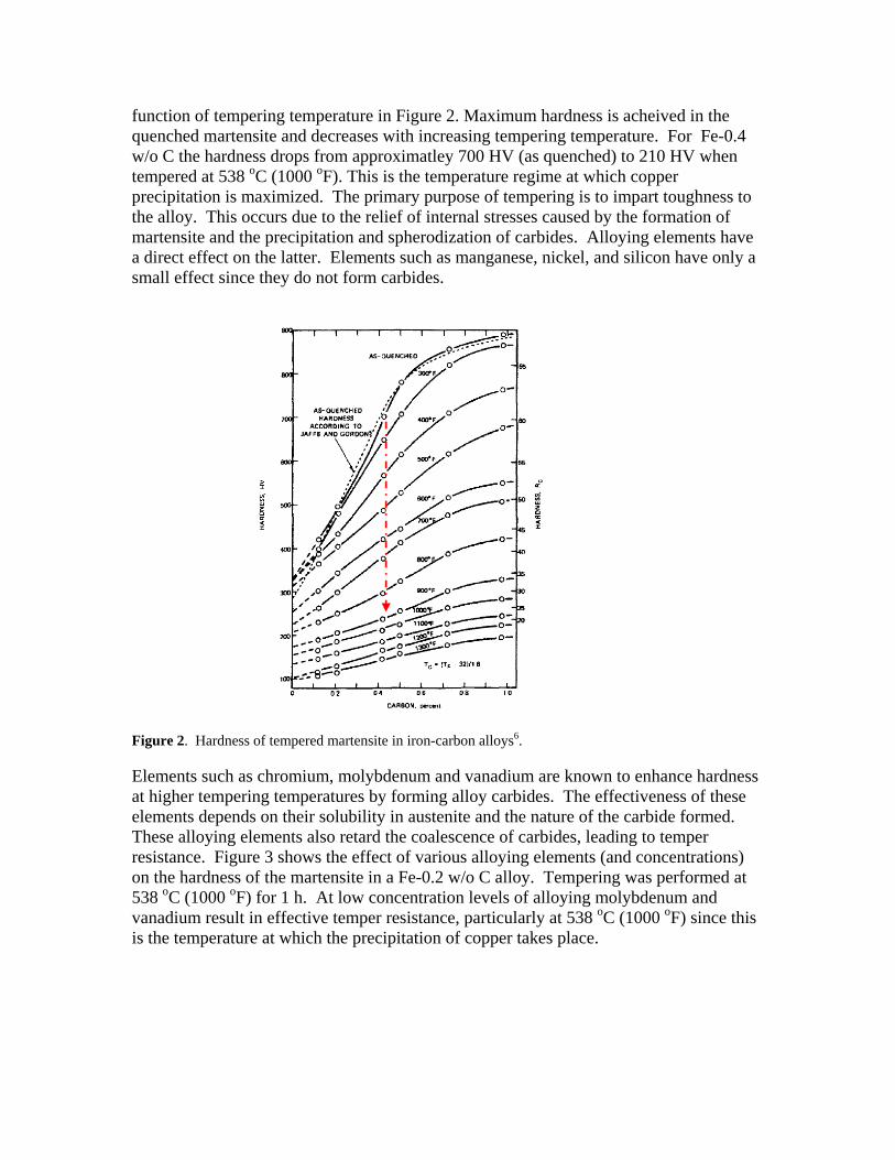
function of tempering temperature in Figure 2. Maximum hardness is acheived in the quenched martensite and decreases with increasing tempering temperature. For Fe-0.4 w/o C the hardness drops from approximatley 700 HV (as quenched) to 210 HV when tempered at 538 oC (1000 oF). This is the temperature regime at which copper precipitation is maximized. The primary purpose of tempering is to impart toughness to the alloy. This occurs due to the relief of internal stresses caused by the formation of martensite and the precipitation and spherodization of carbides. Alloying elements have a direct effect on the latter. Elements such as manganese, nickel, and silicon have only a small effect since they do not form carbides.
Figure 2. Hardness of tempered martensite in iron-carbon alloys6. Elements such as chromium, molybdenum and vanadium are known to enhance hardness at higher tempering temperatures by forming alloy carbides. The effectiveness of these elements depends on their solubility in austenite and the nature of the carbide formed. These alloying elements also retard the coalescence of carbides, leading to temper resistance. Figure 3 shows the effect of various alloying elements (and concentrations) on the hardness of the martensite in a Fe-0.2 w/o C alloy. Tempering was performed at 538 oC (1000 oF) for 1 h. At low concentration levels of alloying molybdenum and vanadium result in effective temper resistance, particularly at 538 oC (1000 oF) since this is the temperature at which the precipitation of copper takes place.
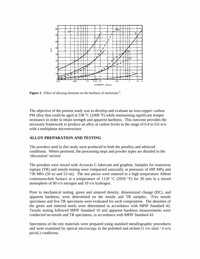
Figure 3. Effect of alloying elements on the hardness of martensite 6. The objective of the present study was to develop and evaluate an iron-copper–carbon PM alloy that could be aged at 538 oC (1000 oF) while maintaining significant temper resistance in order to retain strength and apparent hardness. This outcome provides the necessary framework to produce an alloy at carbon levels in the range of 0.4 to 0.6 w/o with a multiphase microstructure. ALLOY PREPARATION AND TESTING The powders used in this study were produced in both the prealloy and admixed conditions. Where pertinent, the processing steps and powder types are detailed in the ‘discussion’ section The powders were mixed with Acrawax C lubricant and graphite. Samples for transverse rupture (TR) and tensile testing were compacted uniaxially at pressures of 690 MPa and 730 MPa (50 tsi and 53 tsi). The test pieces were sintered in a high temperature Abbott continuous-belt furnace at a temperature of 1120 °C (2050 °F) for 30 min in a mixed atmosphere of 90 v/o nitrogen and 10 v/o hydrogen. Prior to mechanical testing, green and sintered density, dimensional change (DC), and apparent hardness, were determined on the tensile and TR samples. Five tensile specimens and five TR specimens were evaluated for each composition. The densities of the green and sintered steels were determined in accordance with MPIF Standard 42. Tensile testing followed MPIF Standard 10 and apparent hardness measurements were conducted on tensile and TR specimens, in accordance with MPIF Standard 43. Specimens of the test materials were prepared using standard metallographic procedures and were examined by optical microscopy in the polished and etched (1 v/o nital / 4 w/o picral.) conditions.
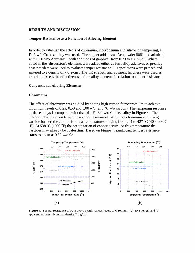
RESULTS AND DISCUSSION Temper Resistance as a Function of Alloying Element In order to establish the effects of chromium, molybdenum and silicon on tempering, a Fe-3 w/o Cu base alloy was used. The copper added was Acupowder 8081 and admixed with 0.60 w/o Acrawax C with additions of graphite (from 0.20 to0.80 w/o). Where noted in the ‘discussion’, elements were added either as ferroalloy additives or prealloy base powders were used to evaluate temper resistance. TR specimens were pressed and sintered to a density of 7.0 g/cm3. The TR strength and apparent hardness were used as criteria to assess the effectiveness of the alloy elements in relation to temper resistance. Conventional Alloying Elements Chromium The effect of chromium was studied by adding high carbon ferrochromium to achieve chromium levels of 0.25, 0.50 and 1.00 w/o (at 0.40 w/o carbon). The tempering response of these alloys is compared with that of a Fe-3.0 w/o Cu base alloy in Figure 4. The effect of chromium on temper resistance is minimal. Although chromium is a strong carbide former, the carbide forms at temperatures ranging from 204 to 427 oC (400 to 800 oF). At 538 oC (1000 oF) the precipitation of copper occurs. At this temperature the carbides may already be coalescing. Based on Figure 4, significant temper resistance starts to occur at 0.50 w/o Cr.
130
140
150
160
170
180
190
200
0 200 400 600 800 1000 1200
960
1040
1120
1200
1280
1360
TRS
(x10
3 psi
)
Tempering Temperature (oF)
0 w/o Chromium
0.25 w/o Chromium
0.50 w/o Chromium
0.75 w/o Chromium
Tempering Temperature (oC)
93 204 315 427 538
TRS
(MPa
)
44
46
48
50
52
54
56
58
60
0 200 400 600 800 1000 1200
0 w/o Chromium
0.25 w/o Chromium
0.50 w/o Chromium
0.75 w/o Chromium
App
aren
t Har
dnes
s (H
RA
)
Tempering Temperature (oC)
93 204 315 427 538
Tempering Temperature (oF)
(a) (b)
Figure 4. Temper resistance of Fe-3 w/o Cu with various levels of chromium: (a) TR strength and (b) apparent hardness. Nominal density 7.0 g/cm3.
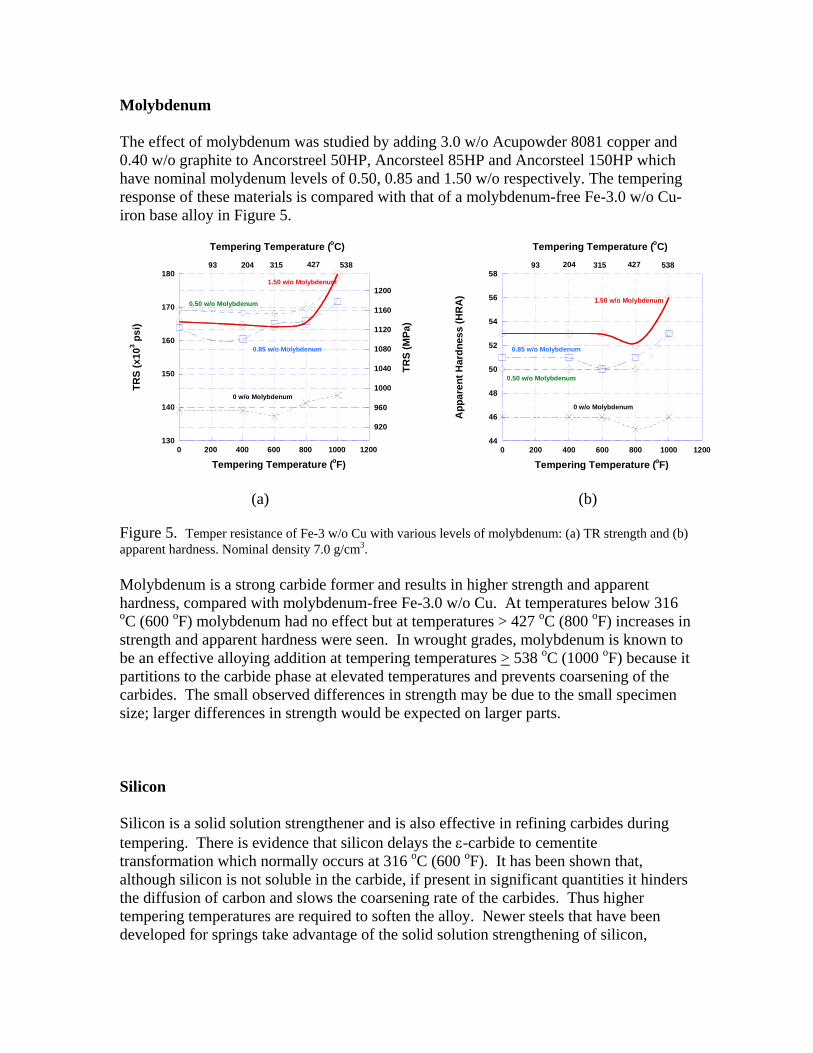
Molybdenum The effect of molybdenum was studied by adding 3.0 w/o Acupowder 8081 copper and 0.40 w/o graphite to Ancorstreel 50HP, Ancorsteel 85HP and Ancorsteel 150HP which have nominal molydenum levels of 0.50, 0.85 and 1.50 w/o respectively. The tempering response of these materials is compared with that of a molybdenum-free Fe-3.0 w/o Cu- iron base alloy in Figure 5.
130
140
150
160
170
180
0 200 400 600 800 1000 1200
920
960
1000
1040
1080
1120
1160
1200
TRS
(x10
3 psi
)
1.50 w/o Molybdenum
0.85 w/o Molybdenum
0.50 w/o Molybdenum
0 w/o Molybdenum
Tempering Temperature (oC)
Tempering Temperature (oF)
93 204 315 427 538
TRS
(MPa
)
44
46
48
50
52
54
56
58
0 200 400 600 800 1000 1200
1.50 w/o Molybdenum
0.85 w/o Molybdenum
0.50 w/o Molybdenum
0 w/o Molybdenum
App
aren
t Har
dnes
s (H
RA
)Tempering Temperature (oF)
Tempering Temperature (oC)
93 204 315 427 538
(a) (b)
Figure 5. Temper resistance of Fe-3 w/o Cu with various levels of molybdenum: (a) TR strength and (b) apparent hardness. Nominal density 7.0 g/cm3. Molybdenum is a strong carbide former and results in higher strength and apparent hardness, compared with molybdenum-free Fe-3.0 w/o Cu. At temperatures below 316 oC (600 oF) molybdenum had no effect but at temperatures > 427 oC (800 oF) increases in strength and apparent hardness were seen. In wrought grades, molybdenum is known to be an effective alloying addition at tempering temperatures > 538 oC (1000 oF) because it partitions to the carbide phase at elevated temperatures and prevents coarsening of the carbides. The small observed differences in strength may be due to the small specimen size; larger differences in strength would be expected on larger parts. Silicon Silicon is a solid solution strengthener and is also effective in refining carbides during tempering. There is evidence that silicon delays the ε-carbide to cementite transformation which normally occurs at 316 oC (600 oF). It has been shown that, although silicon is not soluble in the carbide, if present in significant quantities it hinders the diffusion of carbon and slows the coarsening rate of the carbides. Thus higher tempering temperatures are required to soften the alloy. Newer steels that have been developed for springs take advantage of the solid solution strengthening of silicon,
coupled with its temper resistance in the production of higher strength – sag resistant components.9
162
164
166
168
170
172
174
0 200 400 600 800 1000 1200
1120
1130
1140
1150
1160
1170
1180
1190
TRS
(x10
3 psi
)
0.20 w/o Silicon
0.40 w/o Silicon
0.60 w/o Silicon
Tempering Temperature (oC)
93 204 315 427 538
TRS
(MPa
)
Tempering Temperature (oF)
49.5
50
50.5
51
51.5
52
52.5
0 200 400 600 800 1000 1200
App
aren
t Har
dnes
s (H
RA
)
Tempering Temperature (F)
0.20 w/o Silicon
0.60 w/o Silicon
0.40 w/o Silicon
Tempering Temperature (oC)
93 204 315 427 538
(a) (b)
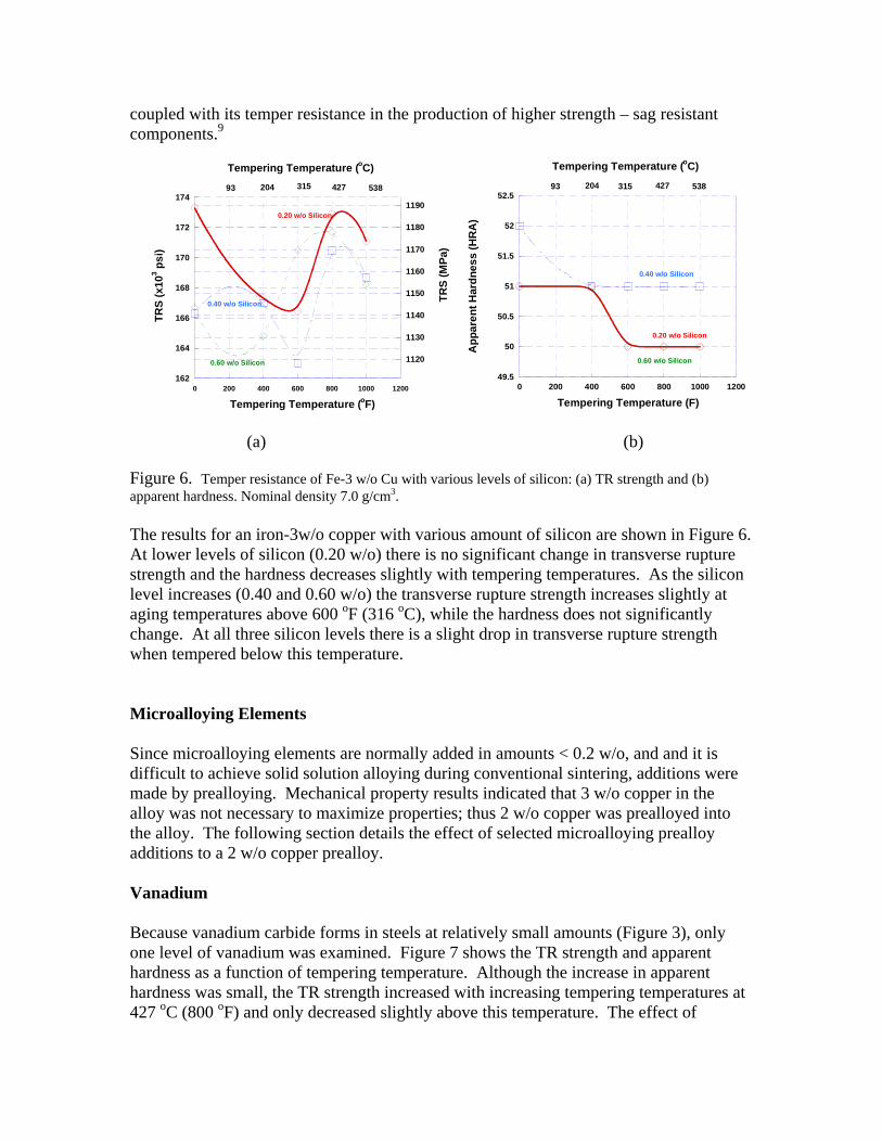
Figure 6. Temper resistance of Fe-3 w/o Cu with various levels of silicon: (a) TR strength and (b) apparent hardness. Nominal density 7.0 g/cm3. The results for an iron-3w/o copper with various amount of silicon are shown in Figure 6. At lower levels of silicon (0.20 w/o) there is no significant change in transverse rupture strength and the hardness decreases slightly with tempering temperatures. As the silicon level increases (0.40 and 0.60 w/o) the transverse rupture strength increases slightly at aging temperatures above 600 oF (316 oC), while the hardness does not significantly change. At all three silicon levels there is a slight drop in transverse rupture strength when tempered below this temperature. Microalloying Elements Since microalloying elements are normally added in amounts < 0.2 w/o, and and it is difficult to achieve solid solution alloying during conventional sintering, additions were made by prealloying. Mechanical property results indicated that 3 w/o copper in the alloy was not necessary to maximize properties; thus 2 w/o copper was prealloyed into the alloy. The following section details the effect of selected microalloying prealloy additions to a 2 w/o copper prealloy. Vanadium Because vanadium carbide forms in steels at relatively small amounts (Figure 3), only one level of vanadium was examined. Figure 7 shows the TR strength and apparent hardness as a function of tempering temperature. Although the increase in apparent hardness was small, the TR strength increased with increasing tempering temperatures at 427 oC (800 oF) and only decreased slightly above this temperature. The effect of
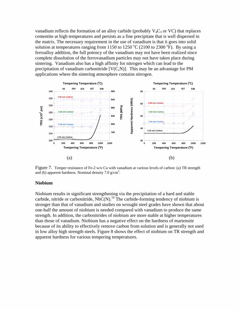
vanadium reflects the formation of an alloy carbide (probably V4C3 or VC) that replaces cementite at high temperatures and persists as a fine precipitate that is well dispersed in the matrix. The necessary requirement in the use of vanadium is that it goes into solid solution at temperatures ranging from 1150 to 1250 oC (2100 to 2300 oF). By using a ferroalloy addition, the full potency of the vanadium may not have been realized since complete dissolution of the ferrovanadium particles may not have taken place during sintering. Vanadium also has a high affinity for nitrogen which can lead to the precipitation of vanadium carbonitride [V(C,N)]. This may be an advantage for PM applications where the sintering atmosphere contains nitrogen.
105
110
115
120
125
130
135
140
0 200 400 600 800 1000 1200
760
800
840
880
920
960
TRS
(x10
3 psi
)
0.80 w/o Carbon
0.60 w/o Carbon
0.40 w/o Carbon
0.20 w/o Carbon
Tempering Temperature (oF)
Tempering Temperature (oC)
93 204 315 427 538
TRS
(MPa
)
35
40
45
50
55
0 200 400 600 800 1000 1200
App
aren
t Har
dnes
s (H
RA
)
Tempering Temperature (oC)
93 204 315 427 538
Tempering Temperature (oF)
0.80 w/o Carbon
0.60 w/o Carbon
0.40 w/o Carbon
0.20 w/o Carbon
(a) (b)
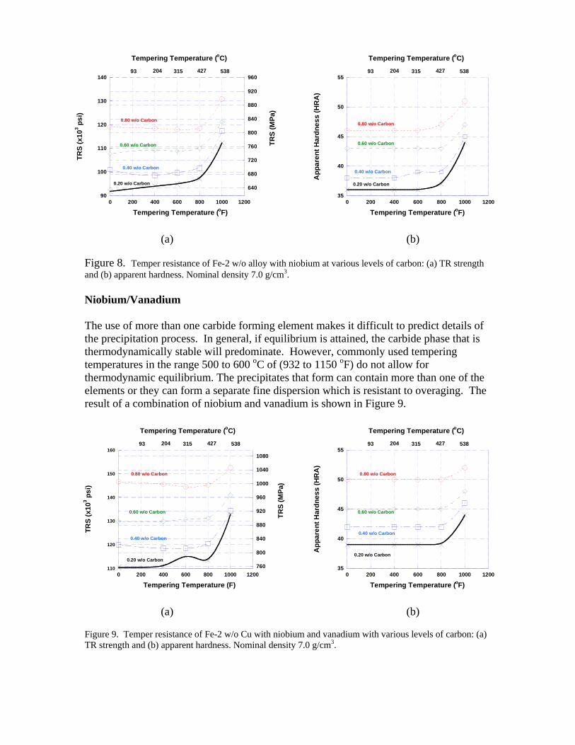
Figure 7. Temper resistance of Fe-2 w/o Cu with vanadium at various levels of carbon: (a) TR strength and (b) apparent hardness. Nominal density 7.0 g/cm3. Niobium Niobium results in significant strengthening via the precipitation of a hard and stable carbide, nitride or carbonitride, NbC(N).10 The carbide-forming tendency of niobium is stronger than that of vanadium and studies on wrought steel grades have shown that about one-half the amount of niobium is needed compared with vanadium to produce the same strength. In addition, the carbonitrides of niobium are more stable at higher temperatures than those of vanadium. Niobium has a negative effect on the hardness of martensite because of its ability to effectively remove carbon from solution and is generally not used in low alloy high strength steels. Figure 8 shows the effect of niobium on TR strength and apparent hardness for various tempering temperatures.
Tempering Temperature (oC) Tempering Temperature (oC)
90
100
110
120
130
140
0 200 400 600 800 1000 1200
640
680
720
760
800
840
880
920
960TR
S (x
103 p
si)
0.20 w/o Carbon
0.40 w/o Carbon
0.60 w/o Carbon
0.80 w/o Carbon
TRS
(MPa
)
Tempering Temperature (oF)
93 204 315 427 538
35
40
45
50
55
0 200 400 600 800 1000 1200
App
aren
t Har
dnes
s (H
RA
)
0.20 w/o Carbon
0.40 w/o Carbon
0.60 w/o Carbon
0.80 w/o Carbon
93 204 315 427 538
Tempering Temperature (oF)
(a) (b)
Figure 8. Temper resistance of Fe-2 w/o alloy with niobium at various levels of carbon: (a) TR strength and (b) apparent hardness. Nominal density 7.0 g/cm3. Niobium/Vanadium The use of more than one carbide forming element makes it difficult to predict details of the precipitation process. In general, if equilibrium is attained, the carbide phase that is thermodynamically stable will predominate. However, commonly used tempering temperatures in the range 500 to 600 oC of (932 to 1150 oF) do not allow for thermodynamic equilibrium. The precipitates that form can contain more than one of the elements or they can form a separate fine dispersion which is resistant to overaging. The result of a combination of niobium and vanadium is shown in Figure 9.
110
120
130
140
150
160
0 200 400 600 800 1000 1200760
800
840
880
920
960
1000
1040
1080
TRS
(x10
3 psi
)
Tempering Temperature (F)
0.20 w/o Carbon
0.40 w/o Carbon
0.60 w/o Carbon
0.80 w/o Carbon
Tempering Temperature (oC)
93 204 315 427 538
TRS
(MPa
)
35
40
45
50
55
0 200 400 600 800 1000 1200
App
aren
t Har
dnes
s (H
RA
)
0.80 w/o Carbon
0.60 w/o Carbon
0.40 w/o Carbon
0.20 w/o Carbon
Tempering Temperature (oC)
Tempering Temperature (oF)
93 204 315 427 538
(a) (b)
Figure 9. Temper resistance of Fe-2 w/o Cu with niobium and vanadium with various levels of carbon: (a) TR strength and (b) apparent hardness. Nominal density 7.0 g/cm3.
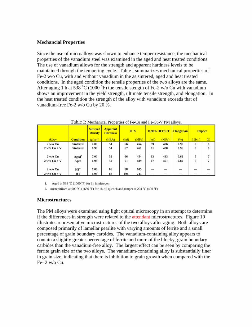
Mechancial Properties Since the use of microalloys was shown to enhance temper resistance, the mechanical properties of the vanadium steel was examined in the aged and heat treated conditions. The use of vanadium allows for the strength and apparent hardness levels to be maintained through the tempering cycle. Table I summarizes mechanical properties of Fe-2 w/o Cu, with and without vanadium in the as sintered, aged and heat treated conditions. In the aged condition the tensile properties of the two alloys are the same. After aging 1 h at 538 oC (1000 oF) the tensile stength of Fe-2 w/o Cu with vanadium shows an improvement in the yield strength, ultimate tensile strength, and elongation. In the heat treated condition the strength of the alloy with vanadium exceeds that of vanadium-free Fe-2 w/o Cu by 20 %.
Table I: Mechanical Properties of Fe-Cu and Fe-Cu-V PM alloys.
1. Aged at 538 oC (1000 F) for 1h in nitrogen
A ench and temper at 204 oC (400 oF)
icrostructures
he PM alloys were examined using light optical microscopy in an attempt to determine
ry
Sintered Density
Apparent Hardness Elongation Impact
Alloy Condition (g/cm3) (HRA) (ksi) (MPa) (ksi) (MPa) (%) ft.lbs.f (J)2 w/o Cu Sintered 7.00 51 66 454 59 406 0.90 6 8
2 w/o Cu + V Sintered 6.98 51 67 461 61 420 0.96 6 8
2 w/o Cu Aged1 7.00 52 66 454 63 433 0.62 5 72 w/o Cu + V Aged 6.98 52 71 489 67 461 0.82 5 7
2 w/o Cu HT2 7.00 66 88 605 --- --- --- --- ---2 w/o Cu + V HT 6.98 68 108 743 --- --- --- --- ---
UTS 0.20% OFFSET
o
2. ustenitiized at 900 oC (1650 oF) for 1h-oil qu
M Tif the differences in strength were related to the attendant microstructures. Figure 10 illustrates representative microstructures of the two alloys after aging. Both alloys arecomposed primarily of lamellar pearlite with varying amounts of ferrite and a small percentage of grain boundary carbides. The vanadium-containing alloy appears to contain a slightly greater percentage of ferrite and more of the blocky, grain boundacarbides than the vanadium-free alloy. The largest effect can be seen by comparing theferrite grain size of the two alloys. The vanadium-containing alloy is substantially finer in grain size, indicating that there is inhibition to grain growth when compared with the Fe- 2 w/o Cu.
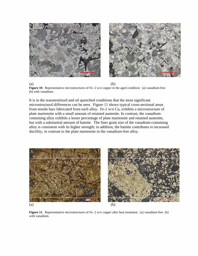
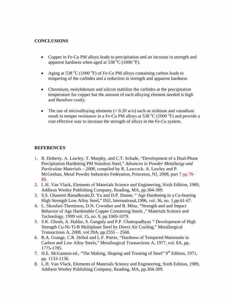
(a) (b) Figure 10. Representative microstructures of Fe- 2 w/o copper in the aged condition: (a) vanadium-free (b) with vanadium. It is in the reaustenitized and oil quenched conditions that the most significant microstructural differences can be seen. Figure 11 shows typical cross-sectional areas from tensile bars fabricated from each alloy. Fe-2 w/o Cu, exhibits a microstructure of plate martensite with a small amount of retained austenite. In contrast, the vanadium-containing alloy exhibits a lesser percentage of plate martensite and retained austenite, but with a substantial amount of bainite. The finer grain size of the vanadium-containing alloy is consistent with its higher strength; in addition, the bainite contributes to increased ductility, in contrast to the plate martensite in the vanadium-free alloy.
(a) (b) Figure 11. Representative microstructures of Fe- 2 w/o copper after heat treatment: (a) vanadium-free (b) with vanadium.
CONCLUSIONS
• Copper in Fe-Cu PM alloys leads to precipitation and an increase in strength and apparent hardness when aged at 538 oC (1000 oF).
• Aging at 538 oC (1000 oF) of Fe-Cu PM alloys containing carbon leads to
tempering of the carbides and a reduction in strength and apparent hardness
• Chromium, molybdenum and silicon stabilize the carbides at the precipitation temperature for copper but the amount of each alloying element needed is high and therefore costly.
• The use of microalloying elements (< 0.20 w/o) such as niobium and vanadium
result in temper resistance in a Fe-Cu PM alloys at 538 oC (1000 oF) and provide a cost effective way to increase the strength of alloys in the Fe-Cu system.
REFERENCES 1. R. Doherty, A. Lawley, T. Murphy, and C.T. Schade, “Development of a Dual-Phase
Precipitation Hardening PM Stainless Steel,” Advances in Powder Metallurgy and Particulate Materials – 2008, compiled by R. Lawcock. A. Lawley and P. McGeehan, Metal Powder Industries Federation, Princeton, NJ, 2008, part 7 pp.78-89.
2. L.H. Van Vlack, Elements of Materials Science and Engineering, Sixth Edition, 1989, Addison Wesley Publishing Company, Reading, MA, pp.304-309.
3. S.S. Ghasemi Banadkouki,D. Yu and D.P. Dunne, “ Age Hardening in a Cu-bearing High Strength Low Alloy Steel,” ISIJ, International,1996, vol. 36, no. 1,pp.61-67.
4. L. Skoufari-Themistou, D.N. Crwother and B. Minz, “Strength and and Impact Behavior of Age Hardenable Copper Containing Steels ,” Materials Science and Technology, 1999 vol. 15, no. 9, pp.1069-1079.
5. S.K. Ghosh, A. Haldar, S. Ganguly and P.P. Chattopadhyay “ Development of High Strength Cu-Ni-Ti-B Multiphase Steel by Direct Air Cooling,” Metallurgical Transactions A, 2008, vol.39A, pp.2555 – 2568.
6. R.A. Grange, C.R. Hribal and L.F. Porter, “Hardness of Tempered Martensite in Carbon and Low Alloy Steels,” Metallurgical Transactions A, 1977, vol. 8A, pp. 1775-1785.
7. H.E. McGannon ed., “The Making, Shaping and Treating of Steel” 9th Edition, 1971, pp. 1133-1136.
8. L.H. Van Vlack, Elements of Materials Science and Engineering, Sixth Edition, 1989, Addison Wesley Publishing Company, Reading, MA, pp.304-309.

9. J. Yan, “ Study of Bauschinger Effect in Various Spring Steels,” M.S. Thesis, 1998, University of Toronto.
10. P.D. Deeley, K.J.A. Kundig and H.R. Spendelow Jr., “Ferroalloys and Alloying Additives Handbook 2nd Addition,” Published by Shieldalloy Metallurgical Corporation, Newfield, New Jersey, 2000.