Embed Size (px)
Citation preview
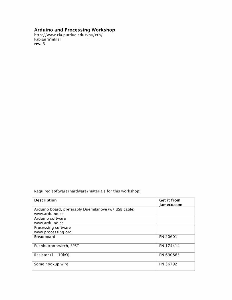
Arduino and Processing Workshop http://www.cla.purdue.edu/vpa/etb/ Fabian Winkler rev. 3 Required software/hardware/materials for this workshop: Description Get it from
Jameco.com Arduino board, preferably Duemilanove (w/ USB cable) www.arduino.cc
Arduino software www.arduino.cc
Processing software www.processing.org
Breadboard
PN 20601
Pushbutton switch, SPST
PN 174414
Resistor (1 – 10kΩ)
PN 690865
Some hookup wire
PN 36792
Winkler, Processing/Arduino workshop, p.2
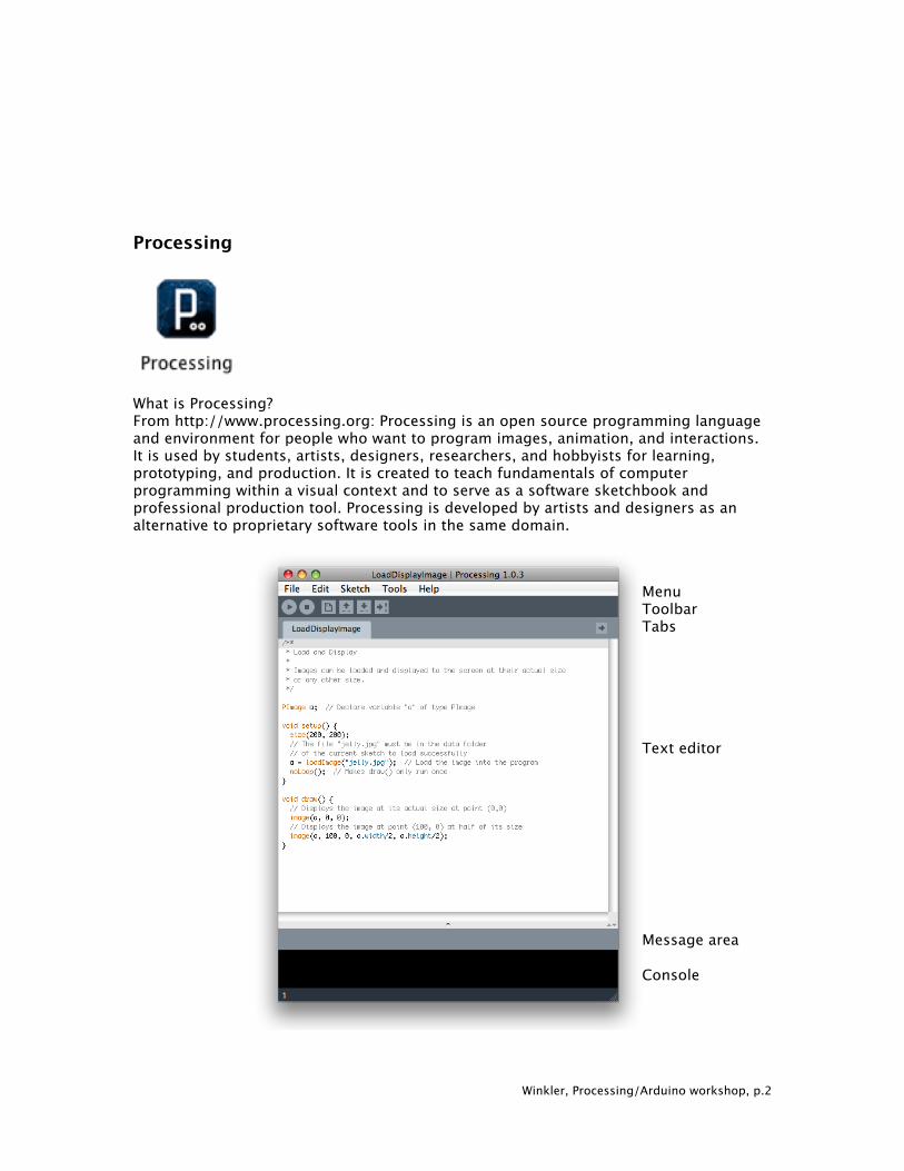
Processing
What is Processing? From http://www.processing.org: Processing is an open source programming language and environment for people who want to program images, animation, and interactions. It is used by students, artists, designers, researchers, and hobbyists for learning, prototyping, and production. It is created to teach fundamentals of computer programming within a visual context and to serve as a software sketchbook and professional production tool. Processing is developed by artists and designers as an alternative to proprietary software tools in the same domain.
Menu Toolbar Tabs Text editor Message area Console
Winkler, Processing/Arduino workshop, p.3
Basic Tips&Tricks
• Mark a word in the Processing code and ctrl click (Macintosh) on it to display information about it in the Processing reference.
• Where can I find my files?
Each sketch resides in its own folder where the main program file is located with the ending “.pde”. You can browse to this folder by choosing Sketch > Show Sketch Folder from the Processing menu.
Example: Sketch name: “Sketch_01", the directory for the sketch will be called "Sketch_01", the main file will be called "Sketch_01.pde".
• Please read “Processing – A Programming Handbook for Visual Designers and
Artists” by Casey Reas and Ben Fry if you are interested in a thorough introduction to the software and its functions. You can also follow the online tutorials at: http://www.processing.org/learning/
Extending Processing’s functionality – libraries Processing has become an extremely powerful scripting environment for the inclusion of almost any type of media – mainly through the concept of libraries. These libraries consist of subroutines and code that extend the functionality of Processing, often to include a particular kind of media (such as video, sound or 3D graphics) or functionality (communications, interface design, fullscreen playback, etc.). To install a library, unzip the file into the “libraries” folder in your sketchbook (on the Macintosh you find the sketchbook in your home directory > Documents > Processing). If you do not already have a libraries folder in your sketchbook, create this folder manually and unzip the files in there. In general, most libraries have instructions on the website where you can download them from, following these directions is the easiest way to install a library. Processing and the Arduino board
For a thorough introduction to the Arduino board see: Banzi, Massimo. Getting Started with Arduino (Make: Projects). Sebastopol, CA: Make Books, 2008. Additionally, you can also read pp. 633-657 in “Processing – A Programming Handbook for Visual Designers and Artists” by Casey Reas and Ben Fry for an excellent introduction on how to connect the Arduino board with Processing and for code and circuit examples.
Winkler, Processing/Arduino workshop, p.4
The following examples are very basic, for more advanced Processing/Arduino interactions read: http://www.arduino.cc/playground/Interfacing/Processing In detail, the next 9 examples illustrate the following ideas:
1) triggering content in Processing reading a pushbutton switch (p. 5) 2) animating a series of still images in Processing (p. 6) 3) animating a sequence of images based on pushing a button (p. 7) 4) randomly triggering images based on pushing a button (p. 8) 5) playing back sounds by pressing a button (p. 9) 6) playing back a Quicktime movie by pressing a button (p. 10) 7) connecting more than one digital (ON/OFF) sensor (p. 11) 8) controlling content in Processing with one analog sensor (p. 19) 9) multiple analog sensors, virtual etch-a-sketch (p. 20)
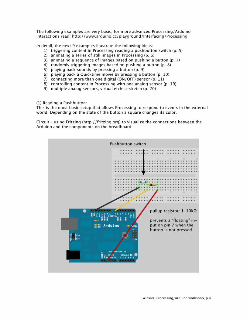
(1) Reading a Pushbutton: This is the most basic setup that allows Processing to respond to events in the external world. Depending on the state of the button a square changes its color. Circuit – using Fritzing (http://fritzing.org) to visualize the connections between the Arduino and the components on the breadboard:
pullup resistor: 1-10kΩ prevents a “floating” in- put on pin 7 when the button is not pressed
Pushbutton switch
Winkler, Processing/Arduino workshop, p.5
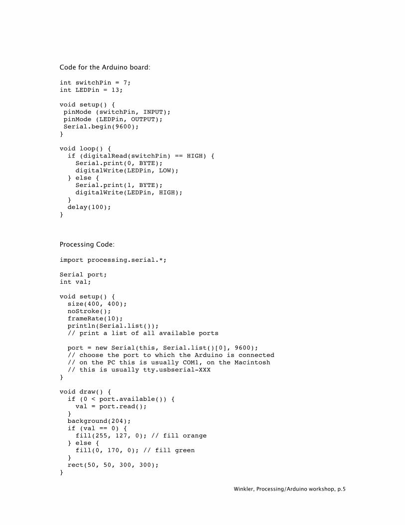
Code for the Arduino board: int switchPin = 7; int LEDPin = 13; void setup() { pinMode (switchPin, INPUT); pinMode (LEDPin, OUTPUT); Serial.begin(9600); } void loop() { if (digitalRead(switchPin) == HIGH) { Serial.print(0, BYTE); digitalWrite(LEDPin, LOW); } else { Serial.print(1, BYTE); digitalWrite(LEDPin, HIGH); } delay(100); } Processing Code: import processing.serial.*; Serial port; int val; void setup() { size(400, 400); noStroke(); frameRate(10); println(Serial.list()); // print a list of all available ports port = new Serial(this, Serial.list()[0], 9600); // choose the port to which the Arduino is connected // on the PC this is usually COM1, on the Macintosh // this is usually tty.usbserial-XXX } void draw() { if (0 < port.available()) { val = port.read(); } background(204); if (val == 0) { fill(255, 127, 0); // fill orange } else { fill(0, 170, 0); // fill green } rect(50, 50, 300, 300); }
Winkler, Processing/Arduino workshop, p.6
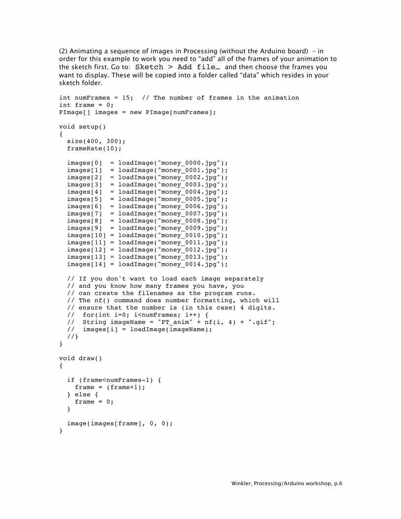
(2) Animating a sequence of images in Processing (without the Arduino board) – in order for this example to work you need to “add” all of the frames of your animation to the sketch first. Go to: Sketch > Add file… and then choose the frames you want to display. These will be copied into a folder called “data” which resides in your sketch folder. int numFrames = 15; // The number of frames in the animation int frame = 0; PImage[] images = new PImage[numFrames]; void setup() { size(400, 300); frameRate(10); images[0] = loadImage("money_0000.jpg"); images[1] = loadImage("money_0001.jpg"); images[2] = loadImage("money_0002.jpg"); images[3] = loadImage("money_0003.jpg"); images[4] = loadImage("money_0004.jpg"); images[5] = loadImage("money_0005.jpg"); images[6] = loadImage("money_0006.jpg"); images[7] = loadImage("money_0007.jpg"); images[8] = loadImage("money_0008.jpg"); images[9] = loadImage("money_0009.jpg"); images[10] = loadImage("money_0010.jpg"); images[11] = loadImage("money_0011.jpg"); images[12] = loadImage("money_0012.jpg"); images[13] = loadImage("money_0013.jpg"); images[14] = loadImage("money_0014.jpg"); // If you don't want to load each image separately // and you know how many frames you have, you // can create the filenames as the program runs. // The nf() command does number formatting, which will // ensure that the number is (in this case) 4 digits. // for(int i=0; i<numFrames; i++) { // String imageName = "PT_anim" + nf(i, 4) + ".gif"; // images[i] = loadImage(imageName); //} } void draw() { if (frame<numFrames-1) { frame = (frame+1); } else { frame = 0; } image(images[frame], 0, 0); }
Winkler, Processing/Arduino workshop, p.7
(3) Animating a sequence of images based on pushing a button The Arduino code and circuit setup is the same as in example 1 Processing code: import processing.serial.*; Serial port; int val = 0; int oldval = 0; int numFrames = 15; // The number of frames in the animation int frame = 0; PImage[] images = new PImage[numFrames]; void setup() { size(400, 300); frameRate(10); images[0] = loadImage("money_0000.jpg"); images[1] = loadImage("money_0001.jpg"); images[2] = loadImage("money_0002.jpg"); images[3] = loadImage("money_0003.jpg"); images[4] = loadImage("money_0004.jpg"); images[5] = loadImage("money_0005.jpg"); images[6] = loadImage("money_0006.jpg"); images[7] = loadImage("money_0007.jpg"); images[8] = loadImage("money_0008.jpg"); images[9] = loadImage("money_0009.jpg"); images[10] = loadImage("money_0010.jpg"); images[11] = loadImage("money_0011.jpg"); images[12] = loadImage("money_0012.jpg"); images[13] = loadImage("money_0013.jpg"); images[14] = loadImage("money_0014.jpg"); // If you don't want to load each image separately // and you know how many frames you have, you // can create the filenames as the program runs. // The nf() command does number formatting, which will // ensure that the number is (in this case) 4 digits. // for(int i=0; i<numFrames; i++) { // String imageName = "PT_anim" + nf(i, 4) + ".gif"; // images[i] = loadImage(imageName); //} println(Serial.list()); // print a list of all available ports port = new Serial(this, Serial.list()[0], 9600); // choose the port to which the Arduino is connected // on the PC this is usually COM1, on the Macintosh // this is usually tty.usbserial-XXX } void draw() { if (0 < port.available()) {
Winkler, Processing/Arduino workshop, p.8
val = port.read(); } if (val != oldval && val == 1) { // the line above makes sure we advance only one frame with // each pressing of the button if (frame<numFrames-1) { frame = (frame+1); } else { frame = 0; } } image(images[frame], 0, 0); oldval = val; } (4) Randomly triggering images based on pushing a button. This example code is very similar to the previous one, only now the images are not played back sequentially but based on the value of a random number. import processing.serial.*; Serial port; int val = 0; int oldval = 0; int numFrames = 15; // The number of frames in the animation int rand_frame = 0; PImage[] images = new PImage[numFrames]; void setup() { size(400, 300); frameRate(10); images[0] = loadImage("money_0000.jpg"); images[1] = loadImage("money_0001.jpg"); images[2] = loadImage("money_0002.jpg"); images[3] = loadImage("money_0003.jpg"); images[4] = loadImage("money_0004.jpg"); images[5] = loadImage("money_0005.jpg"); images[6] = loadImage("money_0006.jpg"); images[7] = loadImage("money_0007.jpg"); images[8] = loadImage("money_0008.jpg"); images[9] = loadImage("money_0009.jpg"); images[10] = loadImage("money_0010.jpg"); images[11] = loadImage("money_0011.jpg"); images[12] = loadImage("money_0012.jpg"); images[13] = loadImage("money_0013.jpg"); images[14] = loadImage("money_0014.jpg"); // If you don't want to load each image separately // and you know how many frames you have, you // can create the filenames as the program runs. // The nf() command does number formatting, which will // ensure that the number is (in this case) 4 digits. // for(int i=0; i<numFrames; i++) {
Winkler, Processing/Arduino workshop, p.9
// String imageName = "PT_anim" + nf(i, 4) + ".gif"; // images[i] = loadImage(imageName); //} println(Serial.list()); // print a list of all available ports port = new Serial(this, Serial.list()[0], 9600); // choose the port to which the Arduino is connected // on the PC this is usually COM1, on the Macintosh // this is usually tty.usbserial-XXX } void draw() { if (0 < port.available()) { val = port.read(); } if (val != oldval && val == 1) { // the line above makes sure we advance only one frame with // each pressing of the button rand_frame = int(random(numFrames-1)); } image(images[rand_frame], 0, 0); oldval = val; } (5) Playing back sounds by pressing a button. This example plays back a sound (and loops it) when the button is pressed. When the button is released the sound stops and it continues to play where it was paused the next time the button is pressed. This example uses the “minim” library (see: http://code.compartmental.net/tools/minim/). You might have to check the Javadocs at: http://code.compartmental.net/minim/javadoc/ to find out all about the methods you can use with certain classes, such as the AudioPlayer class. import processing.serial.*; import ddf.minim.*; Minim minim; AudioPlayer mySound; Serial port; int val = 0; int oldval = 0; int playback_pos = 0; void setup() { size(400, 400); noStroke(); frameRate(10); println(Serial.list()); // print a list of all available ports port = new Serial(this, Serial.list()[0], 9600); // choose the port to which the Arduino is connected // on the PC this is usually COM1, on the Macintosh
Winkler, Processing/Arduino workshop, p.10
// this is usually tty.usbserial-XXX minim = new Minim(this); mySound = minim.loadFile("expressway.aiff"); // make sure you the file “expressway.aiff” in your “data” folder fill(255, 127, 0); } void draw() { if (0 < port.available()) { val = port.read(); } background(204); if (val != oldval && val == 1) { // the line above makes sure we only trigger the sound once // when the pushbutton is pressed & held down fill(0, 170, 0); // fill green mySound.play(playback_pos); // print("played back at: "); // println(playback_pos); // continues to playback where the sound was paused by // remembering the playback head's position mySound.loop(); } if (val != oldval && val == 0) { // the line above makes sure we only pause the sound once // when the pushbutton is released fill(255, 127, 0); // fill orange playback_pos = mySound.position(); // print("paused at: "); // println(playback_pos); // saves the position of the playback head when paused mySound.pause(); } rect(50, 50, 300, 300); oldval = val; } void stop() { // always close Minim audio classes when you are done with them mySound.close(); minim.stop(); super.stop(); } (6) Playback a Quicktime movie. This example shows how you can play back a Quicktime video by pressing a button connected to the Arduino board. Whenever the button is pressed the video starts playing back, when the button is released the video pauses.
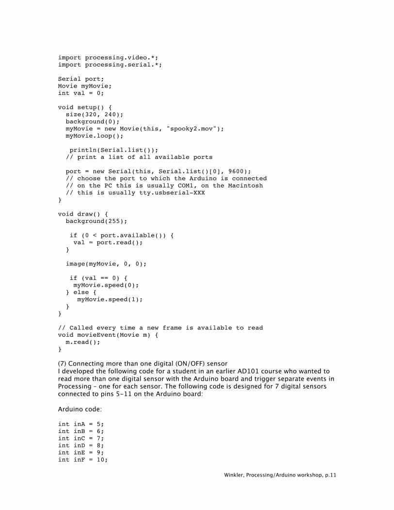
Winkler, Processing/Arduino workshop, p.11
import processing.video.*; import processing.serial.*; Serial port; Movie myMovie; int val = 0; void setup() { size(320, 240); background(0); myMovie = new Movie(this, "spooky2.mov"); myMovie.loop(); println(Serial.list()); // print a list of all available ports port = new Serial(this, Serial.list()[0], 9600); // choose the port to which the Arduino is connected // on the PC this is usually COM1, on the Macintosh // this is usually tty.usbserial-XXX } void draw() { background(255); if (0 < port.available()) { val = port.read(); } image(myMovie, 0, 0); if (val == 0) { myMovie.speed(0); } else { myMovie.speed(1); } } // Called every time a new frame is available to read void movieEvent(Movie m) { m.read(); } (7) Connecting more than one digital (ON/OFF) sensor I developed the following code for a student in an earlier AD101 course who wanted to read more than one digital sensor with the Arduino board and trigger separate events in Processing – one for each sensor. The following code is designed for 7 digital sensors connected to pins 5-11 on the Arduino board: Arduino code: int inA = 5; int inB = 6; int inC = 7; int inD = 8; int inE = 9; int inF = 10;
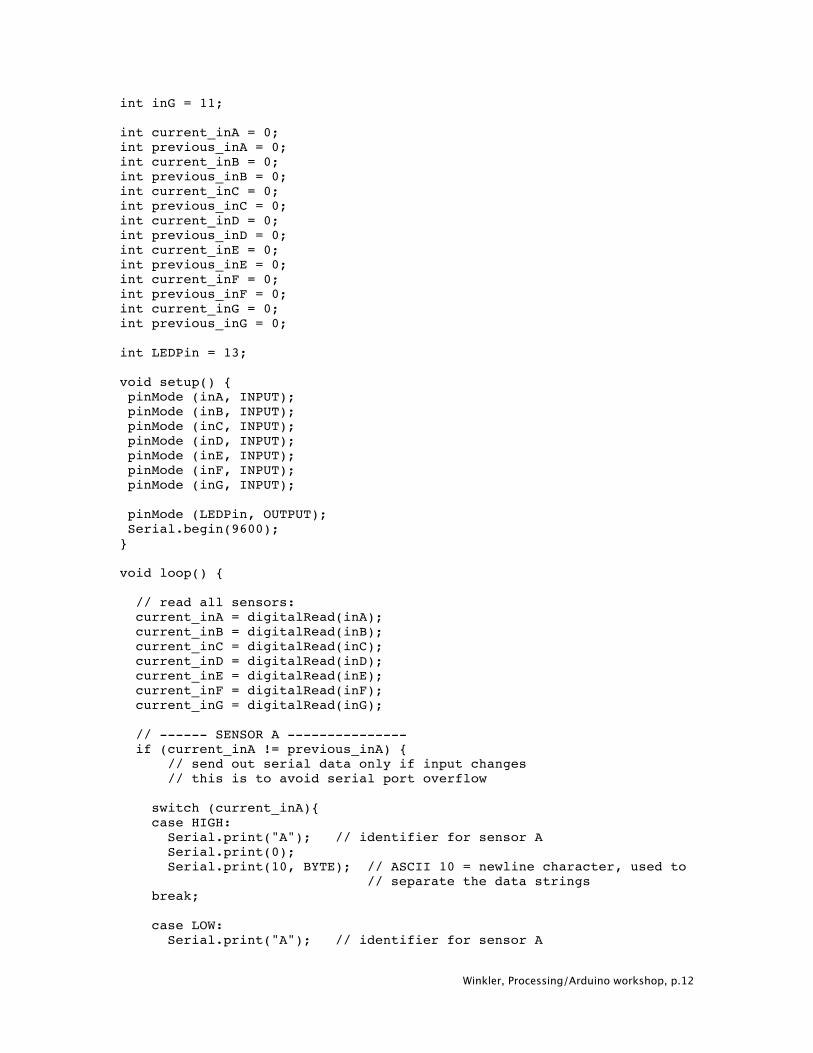
Winkler, Processing/Arduino workshop, p.12
int inG = 11; int current_inA = 0; int previous_inA = 0; int current_inB = 0; int previous_inB = 0; int current_inC = 0; int previous_inC = 0; int current_inD = 0; int previous_inD = 0; int current_inE = 0; int previous_inE = 0; int current_inF = 0; int previous_inF = 0; int current_inG = 0; int previous_inG = 0; int LEDPin = 13; void setup() { pinMode (inA, INPUT); pinMode (inB, INPUT); pinMode (inC, INPUT); pinMode (inD, INPUT); pinMode (inE, INPUT); pinMode (inF, INPUT); pinMode (inG, INPUT); pinMode (LEDPin, OUTPUT); Serial.begin(9600); } void loop() { // read all sensors: current_inA = digitalRead(inA); current_inB = digitalRead(inB); current_inC = digitalRead(inC); current_inD = digitalRead(inD); current_inE = digitalRead(inE); current_inF = digitalRead(inF); current_inG = digitalRead(inG); // ------ SENSOR A --------------- if (current_inA != previous_inA) {
// send out serial data only if input changes // this is to avoid serial port overflow switch (current_inA){ case HIGH: Serial.print("A"); // identifier for sensor A Serial.print(0); Serial.print(10, BYTE); // ASCII 10 = newline character, used to
// separate the data strings break; case LOW: Serial.print("A"); // identifier for sensor A
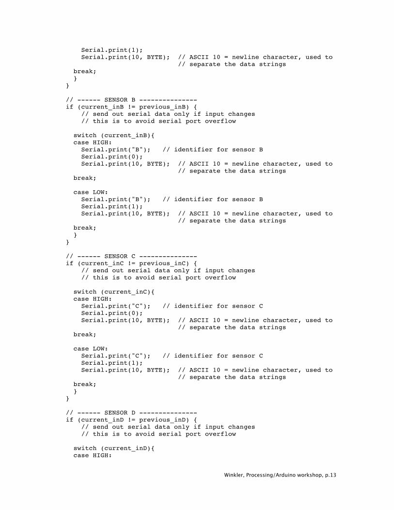
Winkler, Processing/Arduino workshop, p.13
Serial.print(1); Serial.print(10, BYTE); // ASCII 10 = newline character, used to
// separate the data strings break; } } // ------ SENSOR B --------------- if (current_inB != previous_inB) {
// send out serial data only if input changes // this is to avoid serial port overflow switch (current_inB){ case HIGH: Serial.print("B"); // identifier for sensor B Serial.print(0); Serial.print(10, BYTE); // ASCII 10 = newline character, used to
// separate the data strings break; case LOW: Serial.print("B"); // identifier for sensor B Serial.print(1); Serial.print(10, BYTE); // ASCII 10 = newline character, used to
// separate the data strings break; } } // ------ SENSOR C --------------- if (current_inC != previous_inC) {
// send out serial data only if input changes // this is to avoid serial port overflow switch (current_inC){ case HIGH: Serial.print("C"); // identifier for sensor C Serial.print(0); Serial.print(10, BYTE); // ASCII 10 = newline character, used to
// separate the data strings break; case LOW: Serial.print("C"); // identifier for sensor C Serial.print(1); Serial.print(10, BYTE); // ASCII 10 = newline character, used to
// separate the data strings break; } } // ------ SENSOR D --------------- if (current_inD != previous_inD) {
// send out serial data only if input changes // this is to avoid serial port overflow switch (current_inD){ case HIGH:
Winkler, Processing/Arduino workshop, p.14
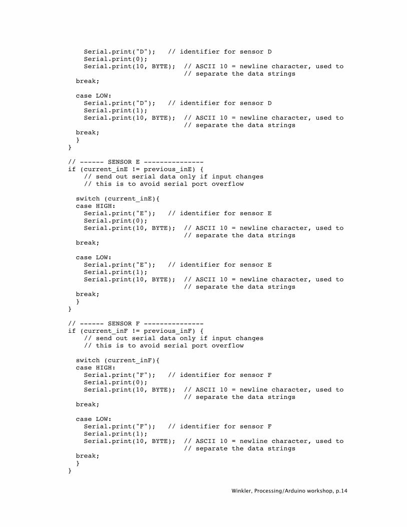
Serial.print("D"); // identifier for sensor D Serial.print(0); Serial.print(10, BYTE); // ASCII 10 = newline character, used to
// separate the data strings break; case LOW: Serial.print("D"); // identifier for sensor D Serial.print(1); Serial.print(10, BYTE); // ASCII 10 = newline character, used to
// separate the data strings break; } } // ------ SENSOR E --------------- if (current_inE != previous_inE) {
// send out serial data only if input changes // this is to avoid serial port overflow switch (current_inE){ case HIGH: Serial.print("E"); // identifier for sensor E Serial.print(0); Serial.print(10, BYTE); // ASCII 10 = newline character, used to
// separate the data strings break; case LOW: Serial.print("E"); // identifier for sensor E Serial.print(1); Serial.print(10, BYTE); // ASCII 10 = newline character, used to
// separate the data strings break; } } // ------ SENSOR F --------------- if (current_inF != previous_inF) {
// send out serial data only if input changes // this is to avoid serial port overflow switch (current_inF){ case HIGH: Serial.print("F"); // identifier for sensor F Serial.print(0); Serial.print(10, BYTE); // ASCII 10 = newline character, used to
// separate the data strings break; case LOW: Serial.print("F"); // identifier for sensor F Serial.print(1); Serial.print(10, BYTE); // ASCII 10 = newline character, used to
// separate the data strings break; } }
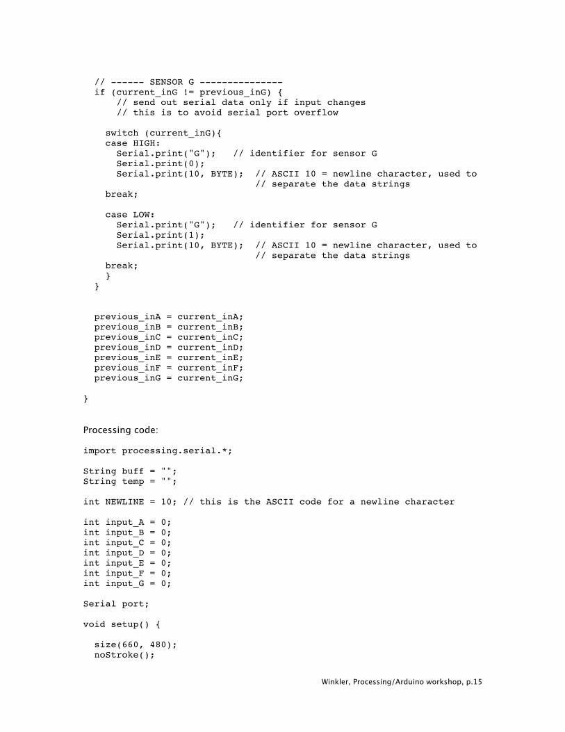
Winkler, Processing/Arduino workshop, p.15
// ------ SENSOR G --------------- if (current_inG != previous_inG) {
// send out serial data only if input changes // this is to avoid serial port overflow switch (current_inG){ case HIGH: Serial.print("G"); // identifier for sensor G Serial.print(0); Serial.print(10, BYTE); // ASCII 10 = newline character, used to
// separate the data strings break; case LOW: Serial.print("G"); // identifier for sensor G Serial.print(1); Serial.print(10, BYTE); // ASCII 10 = newline character, used to
// separate the data strings break; } } previous_inA = current_inA; previous_inB = current_inB; previous_inC = current_inC; previous_inD = current_inD; previous_inE = current_inE; previous_inF = current_inF; previous_inG = current_inG; } Processing code: import processing.serial.*; String buff = ""; String temp = ""; int NEWLINE = 10; // this is the ASCII code for a newline character int input_A = 0; int input_B = 0; int input_C = 0; int input_D = 0; int input_E = 0; int input_F = 0; int input_G = 0; Serial port; void setup() { size(660, 480); noStroke();
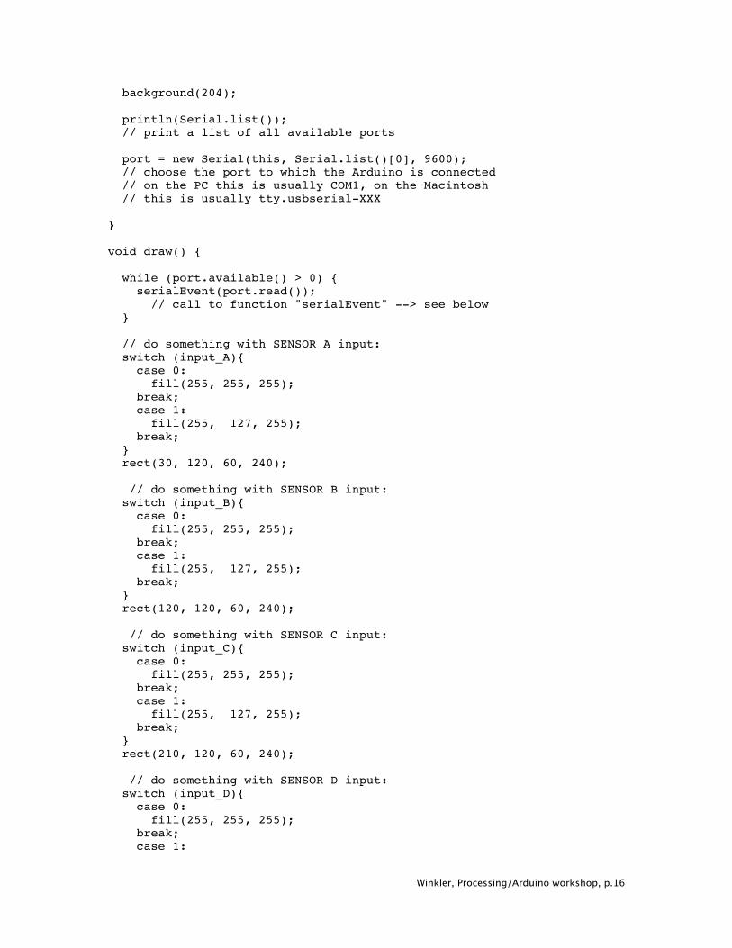
Winkler, Processing/Arduino workshop, p.16
background(204); println(Serial.list()); // print a list of all available ports port = new Serial(this, Serial.list()[0], 9600); // choose the port to which the Arduino is connected // on the PC this is usually COM1, on the Macintosh // this is usually tty.usbserial-XXX } void draw() { while (port.available() > 0) { serialEvent(port.read());
// call to function "serialEvent" --> see below } // do something with SENSOR A input: switch (input_A){ case 0: fill(255, 255, 255); break; case 1: fill(255, 127, 255); break; } rect(30, 120, 60, 240); // do something with SENSOR B input: switch (input_B){ case 0: fill(255, 255, 255); break; case 1: fill(255, 127, 255); break; } rect(120, 120, 60, 240); // do something with SENSOR C input: switch (input_C){ case 0: fill(255, 255, 255); break; case 1: fill(255, 127, 255); break; } rect(210, 120, 60, 240); // do something with SENSOR D input: switch (input_D){ case 0: fill(255, 255, 255); break; case 1:
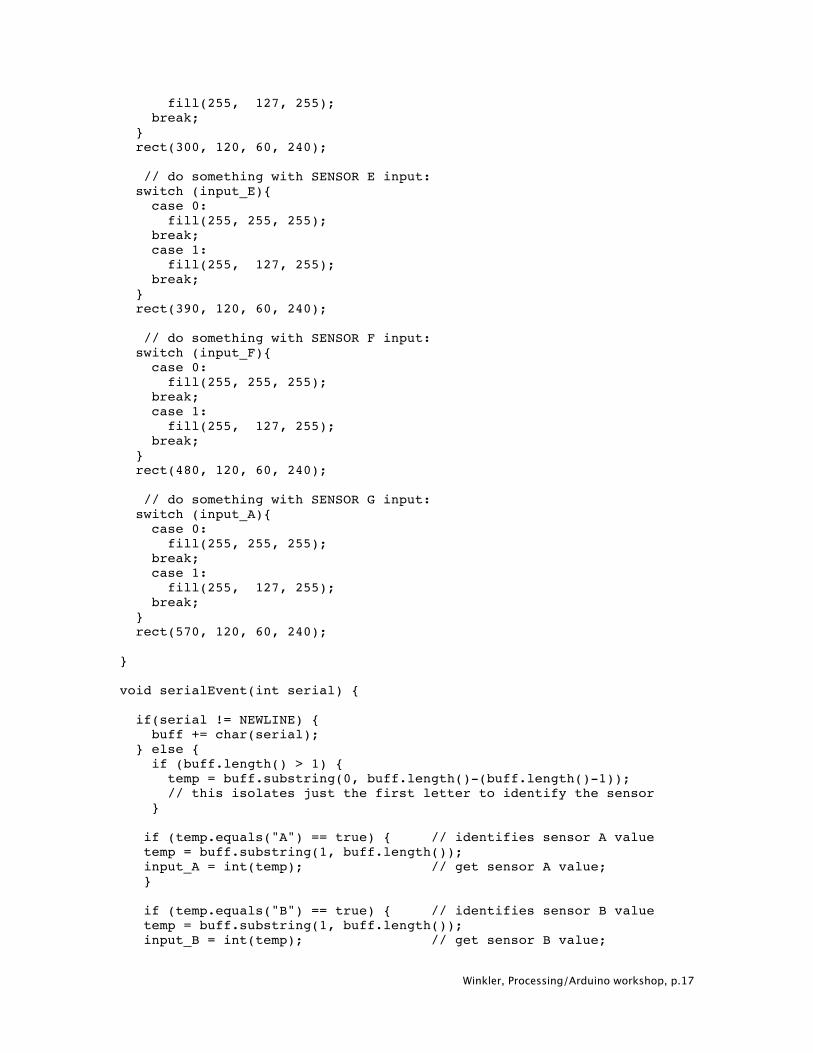
Winkler, Processing/Arduino workshop, p.17
fill(255, 127, 255); break; } rect(300, 120, 60, 240); // do something with SENSOR E input: switch (input_E){ case 0: fill(255, 255, 255); break; case 1: fill(255, 127, 255); break; } rect(390, 120, 60, 240); // do something with SENSOR F input: switch (input_F){ case 0: fill(255, 255, 255); break; case 1: fill(255, 127, 255); break; } rect(480, 120, 60, 240); // do something with SENSOR G input: switch (input_A){ case 0: fill(255, 255, 255); break; case 1: fill(255, 127, 255); break; } rect(570, 120, 60, 240); } void serialEvent(int serial) { if(serial != NEWLINE) { buff += char(serial); } else { if (buff.length() > 1) { temp = buff.substring(0, buff.length()-(buff.length()-1));
// this isolates just the first letter to identify the sensor } if (temp.equals("A") == true) { // identifies sensor A value temp = buff.substring(1, buff.length()); input_A = int(temp); // get sensor A value; } if (temp.equals("B") == true) { // identifies sensor B value temp = buff.substring(1, buff.length()); input_B = int(temp); // get sensor B value;
Winkler, Processing/Arduino workshop, p.18
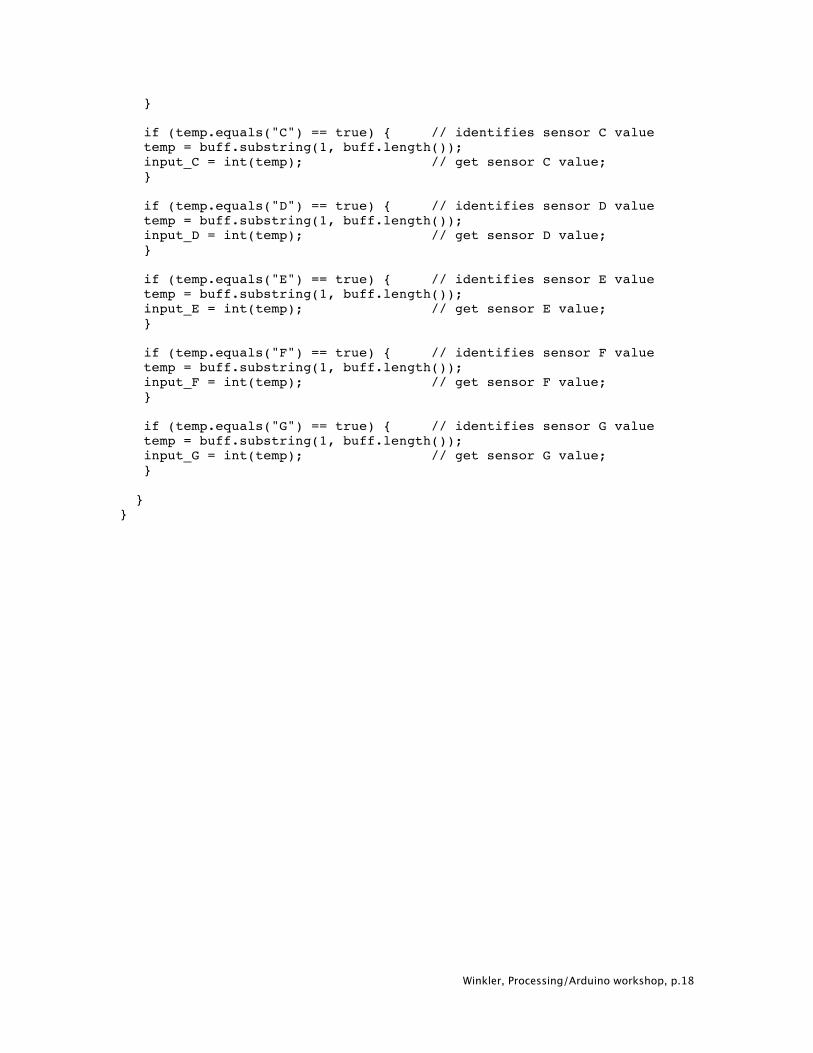
} if (temp.equals("C") == true) { // identifies sensor C value temp = buff.substring(1, buff.length()); input_C = int(temp); // get sensor C value; } if (temp.equals("D") == true) { // identifies sensor D value temp = buff.substring(1, buff.length()); input_D = int(temp); // get sensor D value; } if (temp.equals("E") == true) { // identifies sensor E value temp = buff.substring(1, buff.length()); input_E = int(temp); // get sensor E value; } if (temp.equals("F") == true) { // identifies sensor F value temp = buff.substring(1, buff.length()); input_F = int(temp); // get sensor F value; } if (temp.equals("G") == true) { // identifies sensor G value temp = buff.substring(1, buff.length()); input_G = int(temp); // get sensor G value; } } }
Winkler, Processing/Arduino workshop, p.19
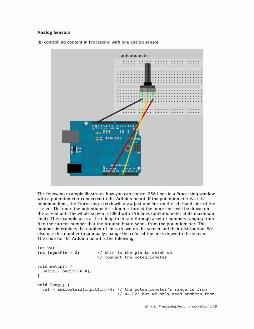
Analog Sensors (8) controlling content in Processing with one analog sensor
The following example illustrates how you can control 256 lines in a Processing window with a potentiometer connected to the Arduino board. If the potentiometer is at its minimum limit, the Processing sketch will draw just one line on the left hand side of the screen. The more the potentiometer’s knob is turned the more lines will be drawn on the screen until the whole screen is filled with 256 lines (potentiometer at its maximum limit). This example uses a for loop to iterate through a set of numbers ranging from 0 to the current number that the Arduino board sends from the potentiometer. This number determines the number of lines drawn on the screen and their distribution. We also use this number to gradually change the color of the lines drawn to the screen. The code for the Arduino board is the following: int val; int inputPin = 2; // this is the pin to which we // connect the potentiometer void setup() { Serial. begin(9600); } void loop() { val = analogRead(inputPin)/4; // the potentiometer’s range is from // 0-1023 but we only need numbers from
potentiometer
Winkler, Processing/Arduino workshop, p.20
// 0-255. Serial.print(val, BYTE); delay (100); } Processing code: import processing.serial.*; Serial port; int val; void setup() { size(1000, 500); //noStroke(); frameRate(10); println(Serial.list()); port = new Serial(this, Serial.list()[0], 9600); // choose the port that the Arduino is // connected to, on a Macintosh choose // the tty.usbserial port } void draw() { if (0 < port.available()) { val = port.read(); } background(204); for (int i = 0; i < val+1; i++) { // this is the “for” loop, see pp.61 // in the book “Processing” by Reas and Fry stroke(255-i, 0, i); // choose the color of the line based on the // potentiometer’s value line (i*5, 100, (i*5)+10, 400); // draw the lines based on the // potentiometer’s value } println(val); // prints out values from Arduino board in // the console, just to see what Processing // actually receives from the Arduino board } (9) multiple analog sensors This example uses two potentiometers to recreate the popular etch-a-sketch toy in Processing. The example is adapted from Christian Nold’s code and was used for a project in my Physical computing class in 2008. Arduino code: int potPin1 = 4; // select the input pin for potentiometer 1 int potPin2 = 5; // select the input pin for potentiometer 2 int val1 = 0; // variable to store the value coming from potentiometer 1
Winkler, Processing/Arduino workshop, p.21
int val2 = 0; // variable to store the value coming from potentiometer 2 void setup() { Serial.begin(9600); } void loop() { val1 = analogRead(potPin1); // read the value from sensor 1 val2 = analogRead(potPin2); // read the value from sensor 2 Serial.print("A"); // Example identifier for sensor 1, send as character Serial.print(val1); // send sensor 1 value as decimal number Serial.print(10, BYTE); // send ASCII string "10" // ASCII 10 = newline character, // used to separate the data strings Serial.print("B"); // Example identifier for sensor 2, send as character Serial.print(val2); // send sensor 2 value as decimal number Serial.print(10, BYTE); // send ASCII string "10" // ASCII 10 = newline character, // used to separate the data strings } Processing code: /* Virtual Etch A Sketch using 2 Potentiometers
This program reads two analog sensors via serial and draws their values as X and Y
Processing Code Christian Nold, 22 Feb 06 slightly modified by Fabian Winkler March 2008 */ import processing.serial.*; String buff = ""; String temp = ""; float temporary = 0.0; float screenwidth = 0.0; float xCoordinate = 0; float yCoordinate = 0; int val = 0; int NEWLINE = 10; Serial port;
Winkler, Processing/Arduino workshop, p.22
void setup() { size(200, 200); strokeWeight(10); // fat stroke(255); smooth(); println(Serial.list()); port = new Serial(this, Serial.list()[0], 9600);
// change [0] to the correct number of your serial port // e.g. tty.usbserial on the Mac and COM1 or COM 2 on the PC } void draw() { fill(0,2); // use black with alpha 2 rectMode(CORNER); rect(0,0,width,height); while (port.available() > 0) { serialEvent(port.read()); } point(xCoordinate, yCoordinate); } void serialEvent(int serial) { if(serial != NEWLINE) { buff += char(serial); } else { if (buff.length() > 1) { temp = buff.substring(0, buff.length()-(buff.length()-1));
// this isolates just the beginning character of the sensor // identified
if(temp.equals("A") == true) { //sensor A value temp = buff.substring(1, buff.length()); temporary = float(temp); xCoordinate = width/(1024/temporary); println(xCoordinate); } if(temp.equals("B") == true) { //sensor B value temp = buff.substring(1, buff.length()); temporary = float(temp); yCoordinate = height/(1024/temporary); println(yCoordinate);

Winkler, Processing/Arduino workshop, p.23
} // Clear the value of "buff" buff = ""; } } }