Embed Size (px)
Citation preview

Process to Instrument Valves: C13SF MonoflangesFor DPharp EJX & EJA-E Pressure Transmitters

Introduction
Introduction
The partnership of Yokogawa and AS-Schneider creates a real added value to our customers.
Yokogawa Electric Corporation with its headquarters in Japan is one of the World's Leading Manufacturers and Engineering Service Provider in the fields of Automation, Measurement, and Control.
The AS-Schneider Group with its headquarters in Germany is one of the World's Lea-ding Manufacturers of Instrumentation Valves and Manifolds. AS-Schneider offers a large variety of Process to Instrument Valves such as Monoflanges and Accessories needed for the instrumentation installations globally.
In this catalogue you will find C13SF Monoflanges for Yokogawa's DPharp EJX Series and EJA Se-ries Pressure Transmitters. The C13SF Monoflanges are designed to overcome the problems of traditional assemblies on primary isolation duties. By combining piping and instrument valves in a single assembly, they provide weight and space savings, along with other benefits including reduced potential leak points and safer hook-up. This more compact and efficient arrangement reduces not only pipework vibration and associated stress but also installation and maintenance costs.
Selection can be made from a comprehensive range of bodies with a variety of connections and material options, optimizing installation and access opportunities. The dimensions shown in this catalog apply to standard types. If you need the dimensions for your individual type please contact Yokogawa.
Continuous product development may from time to time necessitate changes in the details contai-ned in this catalogue. AS-Schneider and Yokogawa reserve the right to make such changes at their discretion and without prior notice.
All dimensions shown in this catalog are approximate and subject to change.
Introduction
Conventional Solution Monoflange
2 Introduction

Monoflanges
3
Monoflanges
The C13SF Monoflanges are designed to replace conventional mutiple-valve installations currently in use for interface with pressure measuring systems. By combining customer specified valves into a single manifold, the number of leak paths is considerably reduced and the weight of the system is lowered reducing the stresses from loading and vibration. The C13SF Monoflange Series are available as Process Monoflanges and Intrument Monoflanges.
Process MonoflangesProcess Monoflanges are designed to replace the traditional primary isolation valve and are close coupled to the process piping flange, for connecting process to instruments. The primary isolation valve needs to be of process / piping design, therefore it's a valve with OS&Y Bolted Bonnet. The secondary isolation valve and the bleed valve are provided with screwed bonnets. The combining of piping and instrument valves into a single unit has benefitted various markets.
Instrument MonoflangesInstrument Monoflanges are close coupled to a pre-installed primary isolation valve to provide a compact Instrument Double Block & Bleed Valve or are used when primary isolation valves with an OS&Y Bolted Bonnet are not required. The needle valves of the Instrument Monoflanges are provided with a screwed bonnet.
Block & Bleed1st Isolate: OS&Y Vent: Needle
Double Block & Bleed1st Isolate: Needle2nd Isolate: NeedleVent: Needle
Block & Bleed1st Isolate: NeedleVent: Needle
Double Block & Bleed1st Isolate: OS&Y2nd Isolate: NeedleVent: Needle
Monoflanges

4
Body Material Options
• Bore Size 5 mm (0.197")
• ASME B16.5 Flange Connections– Flange Size 1/2" to 3" (DN15 to DN80)– Flange Class 150 to 2,500
• API Flange Connections (up to 689 bar [10,000 psi])
• Outlet Connection 1/2 NPT Female
• Vent Connection 1/4 NPT Female
• Anti-Tamper Head Unit Options see Page 8.
• Monoflanges with OS&Y Bolted Bonnet and Graphite Packing are Fire Safe Tested and Certified according to ISO 10497 / API 607. See also Page 7.
Needle Seal:PTFE and Graphite Packings are available for all valve types.
Sour Gas Service:Wetted parts according to a.m. material list are supplied as standard according to NACE MR0175/MR0103 and ISO 15156 (latest issue).
Pressure Test:A shell test and a seat leakage test are performed at 1.5 times the max. allowable (Working) Pressure (PS) acc. to EN 12266-1 – P10, P11 and P12 respectively MSS-SP61 (and complies also with ASME B31.1 and B31.3) and also acc. to API 598 at every Standard Monoflange g 100% Pressure Tested.
Certification:Pressure Test Certificate and Certified Mill Test Report (CMTR) as inspection Certificate 3.1 acc. to EN 10 204 for valve body material available as standard.
The manifolds can be provided with a• CRN Certificate• EAC Certificate – Monoflanges are marked with EAC
• Bore Size 10 mm (0.39") – On request
• EN 1092-1 Flange Connections
• Swivel Gauge Connections – Integral Type see Page 9 (Option Code LGQ), 1/2NPT Swivel Gauge Adapters (supplied loose) Option Code LNQ and JNQ see Page 10 and Ordering Information Pages 13-14. Fugitive Emission Application:For Fugitive Emission Applications we are providing TA-Luft and ISO 15848 solutions. For more details see Page 7.
Oxygen Service:An option with Reinforced PTFE Packing is offerd duly cleaned and lubricated for Oxygen Service:
Pressure-Temperature Rating:Max. 420 bar (6,092 psi) @ 60°C (140°F)Max. 200°C (392°F) @ 90 bar (1,305 psi)
Not every Valve Type is available for Oxygen Service.
If you don't find your options in this catalogue, please contact the factory.
Note: Quadruple certified means 316 / 316L / 1.4401 /1.4404
Please contact Yokogawa affiliate for other Body material.
Standard Features Optional Features
Note:
Starting from 1 1/2'' Class 900 / 1,500 the Valve
Head Units are 45° angled for convenient
operation.
General Features
Material GroupAS Material Designation
Material No. Short NameEquivalent UNS-No.
Material Grade
acc. to ASTM acc. to JIS
Austenitic StainlessSteel
316 quadruplecertified
1.4401 X5CrNiMo17-12-2 S31600 316 SUS316
1.4404 X2CrNiMo17-12-2 S31603 316L SUS316L
General Features

Standard Valve Head Units
5
ComponentsStainless Steel
Material / Material No.
Body
316 / 316LBonnet
Needle
Pipe Plug
Valve Stem 316 / 316L
Gland 316
Packing PTFE or Graphite
Stem Nut/Yoke 316
Lock Nut 316
Set Screw 316
T Handle 316
Lock Pin A4 (316)
Screwed Bonnet – Needle Seal: Packing
Features
• Integral Valve Seat – Metal to metal seated• Non-rotating Needle• External Stem Thread – Packing below stem threads.
Stem threads are protected from process media(non-wetted).
• Stem with Cold Rolled Threads• Blow-out Proof Needle• Back Seat – Metal to metal secondary needle seal• Lock Pin – Eliminates unauthorized removal of the bonnet• Color Coded Dust Cap for operating thread protection• Needle Seal:
Standard Packing in PTFE and Graphiteor Reinforced PTFE – TA-Luft Option
• Max. allowable (Working) Pressure (PS): 420 bar (6,092 psi)– 689 bar (10,000 psi) (PTFE Packing only)
• Anti-Tamper Valve Head Options available• All Non-wetted Parts in 316 Stainless Steel
Standard Needle Valves
Color Coded Dust CapFor stem thread protection:
• Isolate blue • Vent / Test red • Equalize green
Color Coded OptionsFollowing options are also color coded below dust cap:
• Oxygen Service white
• Graphite Packing black • TA-Luft Option magenta
For example
TA-Luft Option
Graphite Packing
Oxygen Service
Wetted components listed in bold.
Standard Valve Head Units
High Pressure Design689 bar (10,000 psi) and
Standard Design420 bar (6,092 psi)
63 (
2.4
8")
ope
n
Body-to-Bonnet Seal is below the threads eliminating process fluid corrosion.
Stan
dar
d: 5
7 (2
.24"
) o
pen
6
Standard Valve Head Units
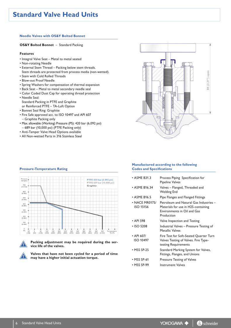
OS&Y Bolted Bonnet – Standard Packing
Features
• Integral Valve Seat – Metal to metal seated• Non-rotating Needle• External Stem Thread – Packing below stem threads.
Stem threads are protected from process media (non-wetted).• Stem with Cold Rolled Threads• Blow-out Proof Needle• Spring Washers for compensation of thermal expansion• Back Seat – Metal to metal secondary needle seal• Color Coded Dust Cap for operating thread protection• Needle Seal:
Standard Packing in PTFE and Graphiteor Reinforced PTFE – TA-Luft Option
• Bonnet Seal Ring: Graphite• Fire Safe approved acc. to ISO 10497 and API 607
– Graphite Packing only• Max. allowable (Working) Pressure (PS): 420 bar (6,092 psi)
– 689 bar (10,000 psi) (PTFE Packing only)• Anti-Tamper Valve Head Options available• All Non-wetted Parts in 316 Stainless Steel
Packing adjustment may be required during the ser-vice life of the valves.
Valves that have not been cycled for a period of time may have a higher initial actuation torque.
Needle Valves with OS&Y Bolted Bonnet
Pressure-Temperature Rating
84
(3.3
1")
ope
n
• ASME B31.3 Process Piping Specification for Pipeline Valves
• ASME B16.34 Valves – Flanged, Threaded and Welding End
• ASME B16.5 Pipe Flanges and Flanged Fittings
• NACE MR0175/ Petroleum and Natural Gas Industries – ISO 15156 Materials for use in H2S-containing Environments in Oil and Gas Production
• API 598 Valve Inspection and Testing
• ISO 5208 Industrial Valves – Pressure Testing of Metallic Valves
• API 607/ Fire Test for Soft-Seated Quarter Turn ISO 10497 Valves Testing of Valves. Fire Type- testing Requirements
• MSS SP-25 Standard Marking System for Valves, Fittings, Flanges, and Unions
• MSS SP-61 Pressure Testing of Valves
• MSS SP-99 Instrument Valves
Manufactured according to the followingCodes and Specifications
Standard Valve Head Units
7
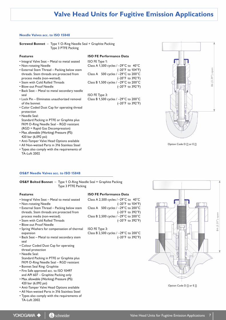
OS&Y Needle Valves acc. to ISO 15848
Valve Head Units for Fugitive Emission Applications
Features
• Integral Valve Seat – Metal to metal seated• Non-rotating Needle• External Stem Thread – Packing below stem
threads. Stem threads are protected from process media (non-wetted).
• Stem with Cold Rolled Threads• Blow-out Proof Needle• Back Seat – Metal to metal secondary needle
seal• Lock Pin – Eliminates unauthorized removal
of the bonnet• Color Coded Dust Cap for operating thread
protection• Needle Seal:
Standard Packing in PTFE or Graphite plusFKM O-Ring Needle Seal – RGD resistant(RGD = Rapid Gas Decompression)
• Max. allowable (Working) Pressure (PS): 420 bar (6,092 psi)
• Anti-Tamper Valve Head Options available• All Non-wetted Parts in 316 Stainless Steel• Types also comply with the requirements of
TA-Luft 2002
ISO FE Performance Data
ISO FE Type 1: Class A 1,500 cycles / –29°C to 40°C (–20°F to 104°F) Class A 500 cycles / –29°C to 200°C (–20°F to 392°F) Class B 1,500 cycles / –29°C to 200°C (–20°F to 392°F)
ISO FE Type 3: Class B 1,500 cycles / –29°C to 200°C (–20°F to 392°F)
Needle Valves acc. to ISO 15848
Screwed Bonnet – Type 1 O-Ring Needle Seal + Graphite Packing Type 3 PTFE Packing
OS&Y Bolted Bonnet – Type 1 O-Ring Needle Seal + Graphite Packing Type 3 PTFE Packing
86
(3.3
9")
ope
n
84
(3.3
1")
ope
n
Features
• Integral Valve Seat – Metal to metal seated• Non-rotating Needle• External Stem Thread – Packing below stem
threads. Stem threads are protected from process media (non-wetted).
• Stem with Cold Rolled Threads• Blow-out Proof Needle• Spring Washers for compensation of thermal
expansion• Back Seat – Metal to metal secondary stem
seal• Colour Coded Dust Cap for operating
thread protection• Needle Seal:
Standard Packing in PTFE or Graphite plusFKM O-Ring Needle Seal – RGD resistant
• Bonnet Seal Ring: Graphite• Fire Safe approved acc. to ISO 10497
and API 607 – Graphite Packing only• Max. allowable (Working) Pressure (PS):
420 bar (6,092 psi)• Anti-Tamper Valve Head Options available• All Non-wetted Parts in 316 Stainless Steel• Types also comply with the requirements of
TA-Luft 2002
ISO FE Performance Data
Class A 2,500 cycles / –29°C to 40°C (–20°F to 104°F) Class A 500 cycles / –29°C to 200°C (–20°F to 392°F) Class B 2,500 cycles / –29°C to 200°C (–20°F to 392°F)
ISO FE Type 3: Class B 2,500 cycles / –29°C to 200°C (–20°F to 392°F)
Valve Head Units for Fugitive Emission Applications
Option Code D [] or E []
Option Code D [] or E []

8
Valve Head Unit Options
Needle Valves according to TA-Luft
The German TA-Luft (Technical Guidelines for Air Pollution Control) gives guidelines for compliance with permissible leak rates. The TA-Luft requirement is considered to be complied with if bellows sealed head units with a safety packing or similar sealing systems are used; whereby the equivalence in the verification system must be confirmed in accordance with VDI 2440.
Special Features
• Max. allowable (Working) Pressure (PS): 420 bar (6,092 psi)
• Cup & Cone Packing (Carbon filled PTFE) – TA-Luft Option
Valve Head Units Options
62 (
2.4
4")
ope
n
Option Code W[]
Screwed Bonnet Bolted Bonnet
Anti-Tamper Valve Head Unit Options
Two types of Anti-Tamper Valve Head Units are offered, both types are lockable with a padlock (not supplied with monoflange). Please refer to Page 15 for detail of Ordering Information.
Stainless Steel Handwheel and 'Locking Plate' Design
The valves can be ordered with Stainless Steel Hand-wheel and Locking Plate Design, also including Pad-lock.
This Design allows Minimum handle movements and is ideal as protection against unauthorized closing of the valve.
Standard Anti-Tamper Head Unit
The valves are operated with a special Anti-Tamper Key (AT-Key), which fits exactly in the key guide. The valve can therefore only be operated with the AT-Key. In addi-tion to this safety function, installing a padlock prevents the AT-Key being inserted into the key guide. Operating the valve is therefore no longer possible which protects your equipment against unauthorized opening and closing of the valve head units. The valve can be locked reliably in every position required.
Option Code L[]
Option Code R[] (with key) or T[] (without key)
Part Number C13SA-ATKES

9
Flanged Instrument Connections
Threaded Instrument Connections
1/2 NPT MaleOption Code JN4
G1/2 Swivel NutOption Code LGQFor Pressure Transmitters with Process Connections G1/2 Maleacc. to EN837-1.
Wafer StyleOption Code NNN
1/2 NPT FemaleOption Code LN4
Connections
Connections

10
Connections
Threaded Instrument Connections (Continued)
Swivel Gauge Adapter 1/2 NPT Female Option Code LNQ Monoflange with 1/2 NPT Female on Instrument Side with Swivel Gauge Adapter (supplied loose)
The Swivel Gauge Adapters enable the easy positioning of the pressure instrument in any direction through 360°.
1/4 NPT
Pipe Plugs (see also Page 14 - Ordering Information: Vent Connection)
1/2 NPT
HEX 14 HEX 22
22 (
0.87
")
25 (
0.99
")
Plugs are supplied in same material as Monoflange body, when specified.
Seal Ring Material:
PTFE Seal Ring - For PTFE packed bonnet options E[], W[], L[] and NN
Metal Seal Ring (Same material as the threaded components) - For Graphite packed bonnet options G[] and D[]
Hex 32
Hex 32
Flat 19
79 (
3.11
")
Hex 27
Hex 32
Flat 19
87.5
(3.
43")
Connections
Swivel Gauge Adapter 1/2 NPT Male Option Code JNQ Monoflange with 1/2 NPT Female on Instrument Side with Swivel Gauge Adapter (supplied loose)
11
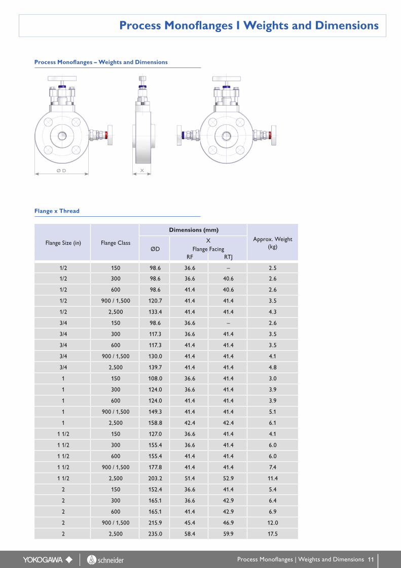
Process Monoflanges I Weights and Dimensions
Ø D X
Flange Size (in) Flange Class
Dimensions (mm)
Approx. Weight (kg)ØD
XFlange Facing
RF RTJ
1/2 150 98.6 36.6 – 2.5
1/2 300 98.6 36.6 40.6 2.6
1/2 600 98.6 41.4 40.6 2.6
1/2 900 / 1,500 120.7 41.4 41.4 3.5
1/2 2,500 133.4 41.4 41.4 4.3
3/4 150 98.6 36.6 – 2.6
3/4 300 117.3 36.6 41.4 3.5
3/4 600 117.3 41.4 41.4 3.5
3/4 900 / 1,500 130.0 41.4 41.4 4.1
3/4 2,500 139.7 41.4 41.4 4.8
1 150 108.0 36.6 41.4 3.0
1 300 124.0 36.6 41.4 3.9
1 600 124.0 41.4 41.4 3.9
1 900 / 1,500 149.3 41.4 41.4 5.1
1 2,500 158.8 42.4 42.4 6.1
1 1/2 150 127.0 36.6 41.4 4.1
1 1/2 300 155.4 36.6 41.4 6.0
1 1/2 600 155.4 41.4 41.4 6.0
1 1/2 900 / 1,500 177.8 41.4 41.4 7.4
1 1/2 2,500 203.2 51.4 52.9 11.4
2 150 152.4 36.6 41.4 5.4
2 300 165.1 36.6 42.9 6.4
2 600 165.1 41.4 42.9 6.9
2 900 / 1,500 215.9 45.4 46.9 12.0
2 2,500 235.0 58.4 59.9 17.5
Flange x Thread
Process Monoflanges – Weights and Dimensions
Process Monoflanges | Weights and Dimensions

12
Flange Size (in) Flange Class
Dimensions (mm)
Approx. Weight (kg)ØD
XFlange Facing
RF RTJ
1/2 300 95.3 33.6 37.6 2.0
1/2 600 95.3 38.4 37.6 2.0
1/2 900 / 1,500 120.7 38.4 38.4 2.9
1/2 2,500 133.4 38.4 38.4 3.7
3/4 150 98.6 33.6 – 2.0
3/4 300 117.3 33.6 38.4 2.9
3/4 600 117.3 38.4 38.4 2.9
3/4 900 / 1,500 130.0 38.4 38.4 3.5
3/4 2,500 139.7 39.4 39.4 4.2
1 150 108.0 33.6 38.4 2.6
1 300 124.0 33.6 38.4 3.3
1 600 124.0 38.4 38.4 3.3
1 900 / 1,500 149.3 38.4 38.4 6.8
1 2,500 158.8 42.4 42.4 5.7
1 1/2 150 127.0 33.6 38.4 3.8
1 1/2 300 155.4 33.6 38.4 5.3
1 1/2 600 155.4 38.4 38.4 5.3
1 1/2 900 / 1,500 177.8 39.4 39.4 6.8
1 1/2 2,500 203.2 51.4 52.9 11.5
2 150 152.4 33.6 38.4 5.1
2 300 165.1 33.6 39.9 5.7
2 600 165.1 38.4 39.9 6.2
2 900 / 1,500 215.9 45.4 46.9 11.6
2 2,500 235.0 58.4 59.9 17.0
Flange x Thread
Instrument Monoflanges – Weights and Dimensions
Ø D X
Instrument Monoflanges I Weights and Dimensions
Instrment Monoflanges I Weights and Dimensions

13
Ordering Information
Ordering Information
Model Suffix Codes Description
Sta
ndar
d F
eatu
res
Proc
ess
Side
ASME Flange Size
NA . . . . . . . . . . . . . . . . . . . . . . . . . . . . . . . . . . . . . . . 1/2'' RF
NC . . . . . . . . . . . . . . . . . . . . . . . . . . . . . . . . . . . . . . . 1/2'' RTJ
ND . . . . . . . . . . . . . . . . . . . . . . . . . . . . . . . . . . . . . . . 3/4'' RF
NF . . . . . . . . . . . . . . . . . . . . . . . . . . . . . . . . . . . . . . . 3/4'' RTJ
NG . . . . . . . . . . . . . . . . . . . . . . . . . . . . . . . . . . . . . . . 1'' RF
NJ . . . . . . . . . . . . . . . . . . . . . . . . . . . . . . . . . . . . . . . 1'' RTJ
NK . . . . . . . . . . . . . . . . . . . . . . . . . . . . . . . . . . . . . . . 1 1/2'' RF
NM . . . . . . . . . . . . . . . . . . . . . . . . . . . . . . . . . . . . . . . 1 1/2'' RTJ
NN . . . . . . . . . . . . . . . . . . . . . . . . . . . . . . . . . . . . . . . 2'' RF
NQ . . . . . . . . . . . . . . . . . . . . . . . . . . . . . . . . . . . . . . . 2'' RTJ
NU . . . . . . . . . . . . . . . . . . . . . . . . . . . . . . . . . . . . . . . 3'' RF
NW . . . . . . . . . . . . . . . . . . . . . . . . . . . . . . . . . . . . . . . 3'' RTJ
API Flange Size SA . . . . . . . . . . . . . . . . . . . . . . . . . . . . . . . . . . . . . . . 1 13/16''
SB . . . . . . . . . . . . . . . . . . . . . . . . . . . . . . . . . . . . . . . 2 1/16''
ASME Flange Class
A . . . . . . . . . . . . . . . . . . . . . . . . . . . . . . . . . . 150
B . . . . . . . . . . . . . . . . . . . . . . . . . . . . . . . . . . 300
C . . . . . . . . . . . . . . . . . . . . . . . . . . . . . . . . . . 600
D . . . . . . . . . . . . . . . . . . . . . . . . . . . . . . . . . . 900*
E . . . . . . . . . . . . . . . . . . . . . . . . . . . . . . . . . . 1,500
F . . . . . . . . . . . . . . . . . . . . . . . . . . . . . . . . . . 2,500
API Flange Rated Working Pressure
G . . . . . . . . . . . . . . . . . . . . . . . . . . . . . . . . . . 5,000 psi
H . . . . . . . . . . . . . . . . . . . . . . . . . . . . . . . . . . 10,000 psi
* Relevant for Flange Sizes ≥ 3" only. For Flange Sizes 1/2" to 2 1/2" Class 1,500 (Code E) to be used.
Model Suffix Codes Description
Sta
ndar
d F
eatu
res C13SF .............................................................. Monoflange (AS-Schneider)
Body Material
S .............................................................. SS316/316L
Valve Type
-D ......................................................... Block & Bleed (OS&Y / Needle)
-G ......................................................... Double Block & Bleed (OS&Y / Needle / Needle)
-N ......................................................... Block & Bleed (Needle / Needle)
-R ......................................................... Double Block & Bleed (Needle / Needle / Needle)

14
Ordering Information
Model Suffix Codes Description
Sta
ndar
d F
eatu
res
Threaded Connections
-LN4 . . . . . . . . . . . . . . . . . . . . . . . 1/2 NPT Female
-LNQ . . . . . . . . . . . . . . . . . . . . . . . 1/2 NPT Female (Swivel Gauge Adapter supplied loose)
-JN4 . . . . . . . . . . . . . . . . . . . . . . . 1/2 NPT Male
-JNQ . . . . . . . . . . . . . . . . . . . . . . . 1/2 NPT Male (Swivel Gauge Adapter supplied loose)
-LGQ . . . . . . . . . . . . . . . . . . . . . . . G 1/2 Female (Integral Swivel Gauge Adapter)
Flanged Connection - NNN . . . . . . . . . . . . . . . . . . . . . . . Wafer Style
Ordering Information
* Plug material is same as Monoflange Body material.
Inst
rum
ent
Side
Model Description
Sta
ndar
d F
eatu
res
Vent Connections
- C . . . . . . . . . . . 1/4 NPT Female
- D . . . . . . . . . . . 1/4 NPT Female plugged*
- E . . . . . . . . . . . 1/2 NPT Female
- F . . . . . . . . . . . 1/2 NPT Female plugged*
Bonnet Options
Graphite Packing, MWP 420 barG2 .......... For Block & Bleed Monoflange
G3 .......... For Double Block & Bleed Monoflange
ISO FE Type 1 - Graphite Packing + O-Ring Stem Seal, MWP 420 bar
D2 .......... For Block & Bleed Monoflange
D3 .......... For Double Block & Bleed Monoflange
ISO FE Type 3 - Reinforced PTFE Packing, MWP 420 bar
E2 .......... For Block & Bleed Monoflange
E3 .......... For Double Block & Bleed Monoflange
TA-Luft - Reinforced PTFE Packing, MWP 420 bar
W2 ......... For Block & Bleed Monoflange
W3 ......... For Double Block & Bleed Monoflange
Arctic Operations -55°C (-67°F) – PTFE Packing
L2 .......... For Block & Bleed Monoflange
L3 .......... For Double Block & Bleed Monoflange
PTFE Packing NN ......... Standard

15
Ordering Information I Example
Ordering Information | Example
Example for building up the Part No. of a Double Block & Bleed Monoflange (OS&Y / Needle / Needle)
C13SFS - G N F E - L N 4 - C G 3 - N N N N
C13SF Monoflange (AS-Schneider)
. . . . . . . .S Material: SS316/316L
. . . . . . . . . . - G Valve Type: Double Block & Bleed (OS&Y / Needle / Needle)
. . . . . . . . . . . . . . .NF ASME Flange Size: 3/4'' RTJ
. . . . . . . . . . . . . . . . . . . E ASME Flange Class: 1,500
. . . . . . . . . . . . . . . . . . . . . . - L N 4 Instrument Connection: 1/2 NPT Female
. . . . . . . . . . . . . . . . . . . . . . . . . . . . . . . . - C Vent Connection: 1/4 NPT Female
. . . . . . . . . . . . . . . . . . . . . . . . . . . . . . . . . . . . G 3 Bonnet Option: Graphite Packing, MWP 500 bar, for 3 Valve
..................................................... - N N N N No additional feature
Suffix Codes Description
Add
itoi
nal F
eatu
res
Cleaning for Oxygen Service – For Monoflanges with PTFE Packing only - Bonnet Option Code -NN or -L[], MWP 420 bar
- K2 ............... For Block & Bleed Monoflange
- K3 ............... For Double Block & Bleed Monoflange
- NN .............. None
Valve Operator
Handwheel with Locking Plate DesignL2 . . . . . . . . . . . . For Block & Bleed Monoflange
L3 . . . . . . . . . . . . For Double Block & Bleed Monoflange
Anti-Tamper without Key
T1 . . . . . . . . . . . For Vent Valve Head Unit
T2 . . . . . . . . . . . For Block & Bleed Monoflange
T3 . . . . . . . . . . . . For Double Block & Bleed Monoflange
Anti-Tamper with Key
R1 . . . . . . . . . . . . For Vent Valve Head Unit
R2 . . . . . . . . . . . . For Block & Bleed Monoflange
R3 . . . . . . . . . . . . For Double Block & Bleed Monoflange
T Handle as Standard NN . . . . . . . . . . . . For all Valve Head Units
Wetted Parts according to above mentioned material list are supplied according to NACE MR0175/MR0103 and ISO 15156 (latest issue).Note: Not every configuration which can be created in the ordering information is feasible / available.

Products are designed and manufactured by Armaturenfabrik Franz Schneider (AS-Schneider) for Yokogawa Electric Corporation.
YS-2001-EN I March 2018
YOKOGAWA ELECTRIC CORPORATIONWorld Headquarters2-9-32, Nakacho, Musashino-shi, Tokyo 180-8750, Japanhttp://www.yokogawa.com
YOKOGAWA CORPORATION OF AMERICA 2 Dart Road, Newnan, GA30265, U.S.A.http://www.yokogawa.com/us/
YOKOGAWA EUROPE B.V.Euroweg 2, 3825 HD Amersfoort, The Netherlandshttp://www.yokogawa.com/eu/
YOKOGAWA ENGINEERING ASIA PTE. LTD.5 Bedok South Road, Singapore 469270http://www.yokogawa.com/sg/
YOKOGAWA CHINA CO., LTD.3F TowerD Cartelo Crocodile Building, No. 568 West Tianshan Road, Shanghai 200335, Chinahttp://www.yokogawa.com/cn/
YOKOGAWA MIDDLE EAST B.S.C.(c)P.O. Box 10070, ManamaBuilding 577, Road 2516, Busaiteen 225, Muharraq, Bahrainhttp://www.yokogawa.com/bh/
Represented by:
ARMATURENFABRIK FRANz SCHNEIDER GMBH + CO. KG World HeadquartersBahnhofplatz 12, 74226 Nordheim, GermanyTel: +49 7133 101-0http://www.as-schneider.com
ARMATURENFABRIK FRANz SCHNEIDER SRLStr. Basarabilor, Nr. 7, 100036 Ploiesti, RomaniaTel: +40 244 384 963http://www.as-schneider.ro
AS-SCHNEIDER MIDDLE EAST FzE P.O. Box 18749, Dubai, United Arab EmiratesTel: +971 4 880 85 75 http://www.as-schneider.ae
AS-SCHNEIDER ASIA-PACIFIC PTE. LTD. 970 Toa Payoh North, #02-12/14/15, Singapore 318992,Singapore Tel: +65 62 51 39 00 http://www.as-schneider.sg
AS-SCHNEIDER AMERICA, INC.17471 Village Green Dr, Houston, TX 77040, U.S.A.Tel: +1 281 760 1025http://www.as-schneider.com
are registered trademarks of Yokogawa Electric Corporation.Other company names and product names used in this material are registered trademarks or trademarks of their respective owners.