Embed Size (px)
Citation preview

Process switches and PLC circuits
This worksheet and all related files are licensed under the Creative Commons Attribution License,version 1.0. To view a copy of this license, visit http://creativecommons.org/licenses/by/1.0/, or send aletter to Creative Commons, 559 Nathan Abbott Way, Stanford, California 94305, USA. The terms andconditions of this license allow for free copying, distribution, and/or modification of all licensed works bythe general public.
1
Questions
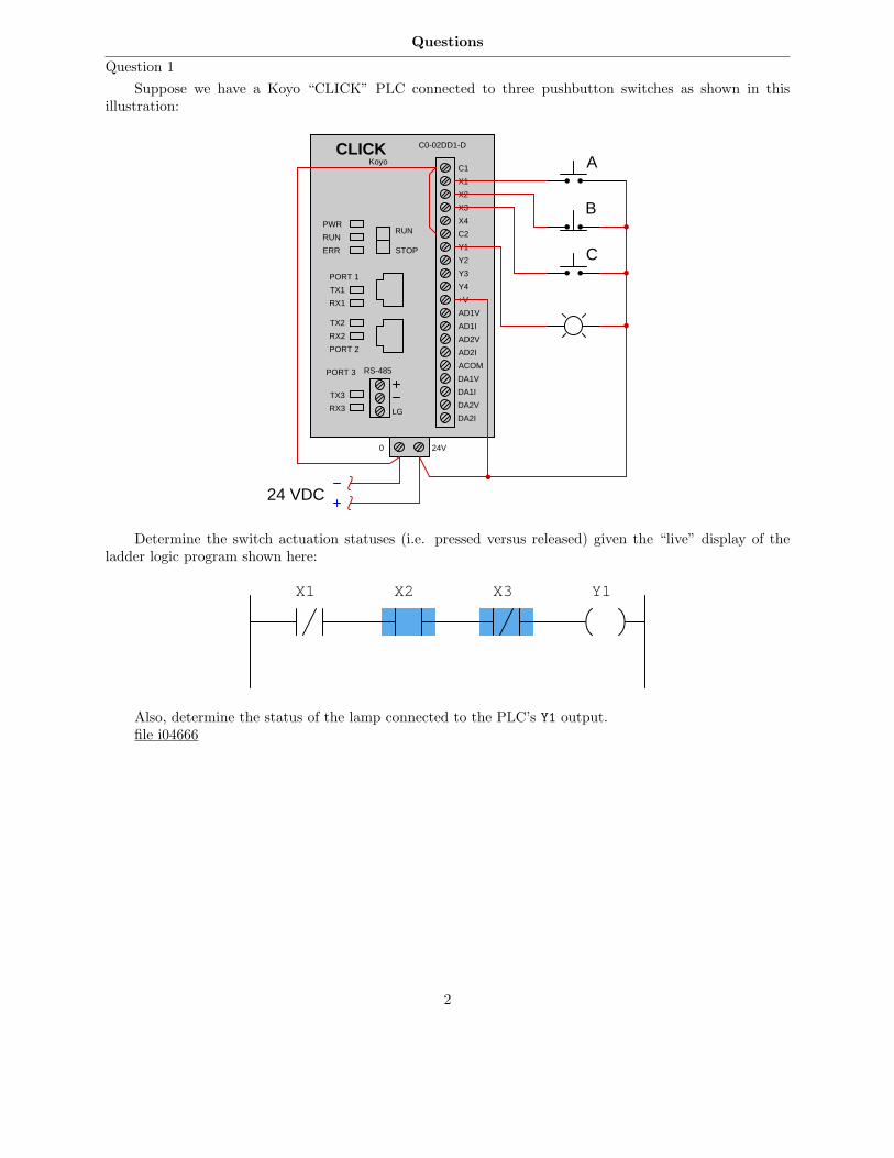
Question 1
Suppose we have a Koyo “CLICK” PLC connected to three pushbutton switches as shown in thisillustration:
RS-485
LG
C1
X1
AD1V
AD1I
AD2V
AD2I
ACOM
DA1V
DA1I
DA2V
DA2I
CLICK
X2
X3
X4
C2
Y1
Y2
Y3
Y4
+V
C0-02DD1-D
Koyo
PWR
RUN
ERR
TX1
RX1
TX2
RX2
RUN
STOP
PORT 1
PORT 2
TX3
RX3
PORT 3
0 24V
24 VDC
A
B
C
Determine the switch actuation statuses (i.e. pressed versus released) given the “live” display of theladder logic program shown here:
X1 X2 X3 Y1
Also, determine the status of the lamp connected to the PLC’s Y1 output.file i04666
2
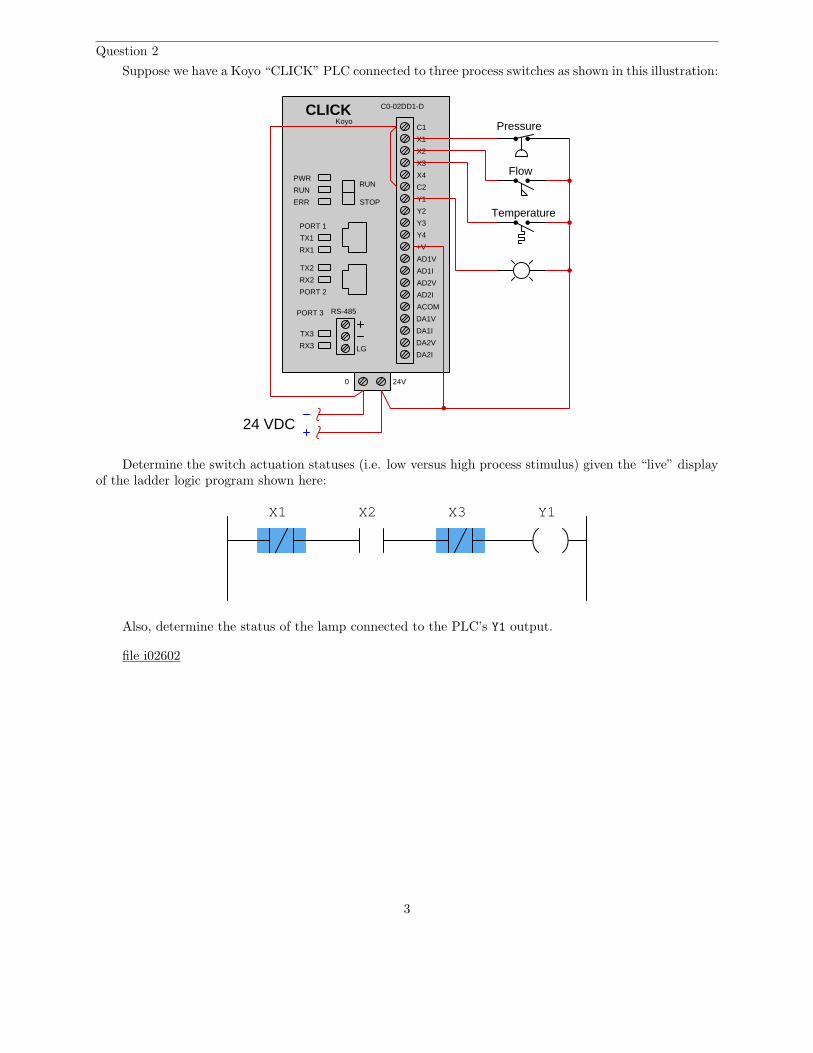
Question 2
Suppose we have a Koyo “CLICK” PLC connected to three process switches as shown in this illustration:
RS-485
LG
C1
X1
AD1V
AD1I
AD2V
AD2I
ACOM
DA1V
DA1I
DA2V
DA2I
CLICK
X2
X3
X4
C2
Y1
Y2
Y3
Y4
+V
C0-02DD1-D
Koyo
PWR
RUN
ERR
TX1
RX1
TX2
RX2
RUN
STOP
PORT 1
PORT 2
TX3
RX3
PORT 3
0 24V
24 VDC
Pressure
Flow
Temperature
Determine the switch actuation statuses (i.e. low versus high process stimulus) given the “live” displayof the ladder logic program shown here:
X1 X2 X3 Y1
Also, determine the status of the lamp connected to the PLC’s Y1 output.
file i02602
3
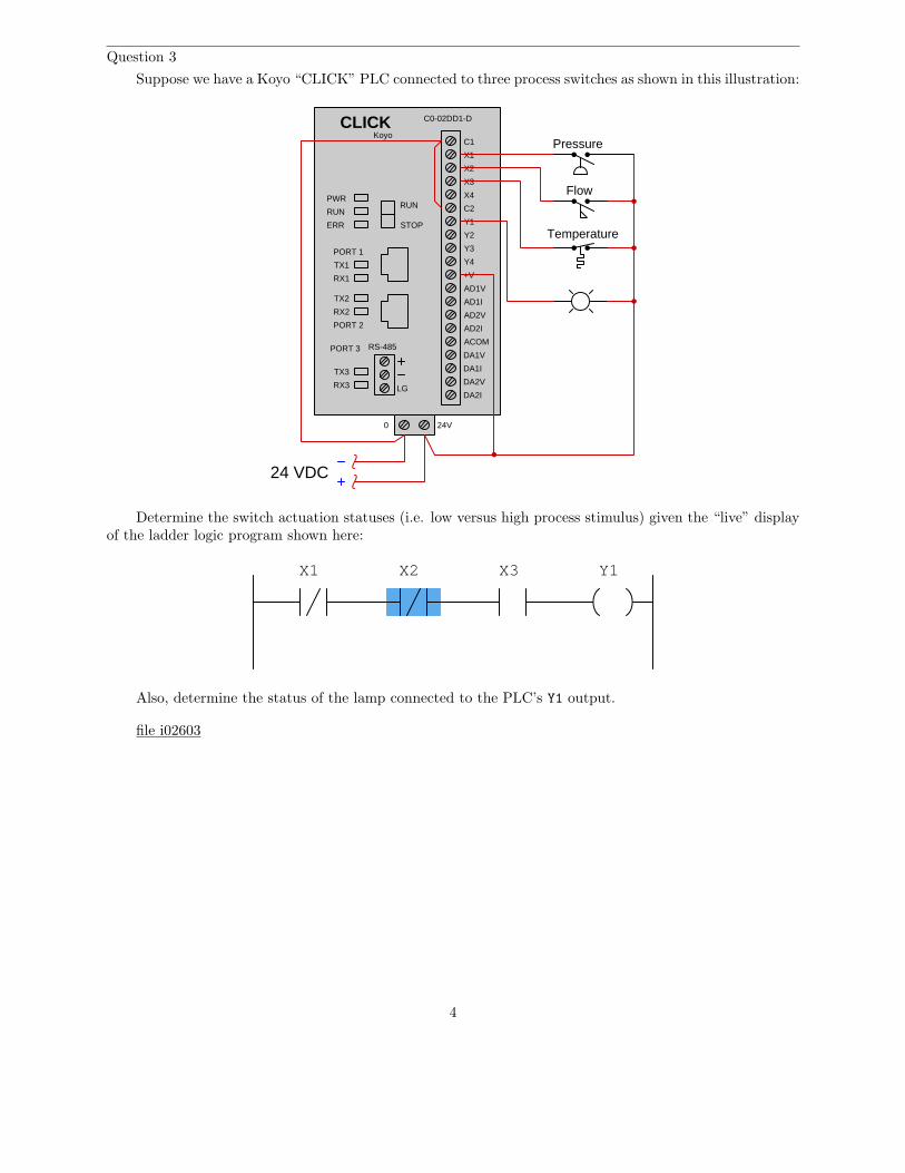
Question 3
Suppose we have a Koyo “CLICK” PLC connected to three process switches as shown in this illustration:
RS-485
LG
C1
X1
AD1V
AD1I
AD2V
AD2I
ACOM
DA1V
DA1I
DA2V
DA2I
CLICK
X2
X3
X4
C2
Y1
Y2
Y3
Y4
+V
C0-02DD1-D
Koyo
PWR
RUN
ERR
TX1
RX1
TX2
RX2
RUN
STOP
PORT 1
PORT 2
TX3
RX3
PORT 3
0 24V
24 VDC
Pressure
Flow
Temperature
Determine the switch actuation statuses (i.e. low versus high process stimulus) given the “live” displayof the ladder logic program shown here:
X1 X2 X3 Y1
Also, determine the status of the lamp connected to the PLC’s Y1 output.
file i02603
4
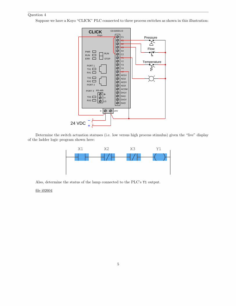
Question 4
Suppose we have a Koyo “CLICK” PLC connected to three process switches as shown in this illustration:
RS-485
LG
C1
X1
AD1V
AD1I
AD2V
AD2I
ACOM
DA1V
DA1I
DA2V
DA2I
CLICK
X2
X3
X4
C2
Y1
Y2
Y3
Y4
+V
C0-02DD1-D
Koyo
PWR
RUN
ERR
TX1
RX1
TX2
RX2
RUN
STOP
PORT 1
PORT 2
TX3
RX3
PORT 3
0 24V
24 VDC
Pressure
Flow
Temperature
Determine the switch actuation statuses (i.e. low versus high process stimulus) given the “live” displayof the ladder logic program shown here:
X1 X2 X3 Y1
Also, determine the status of the lamp connected to the PLC’s Y1 output.
file i02604
5
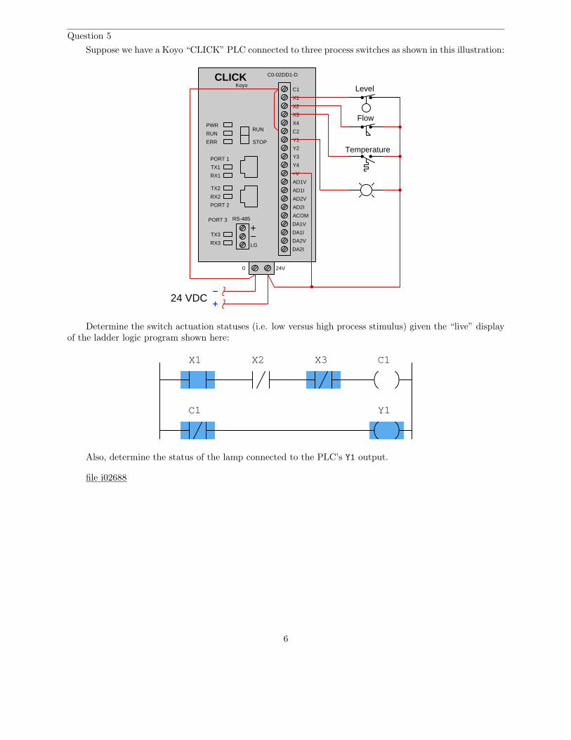
Question 5
Suppose we have a Koyo “CLICK” PLC connected to three process switches as shown in this illustration:
RS-485
LG
C1
X1
AD1V
AD1I
AD2V
AD2I
ACOM
DA1V
DA1I
DA2V
DA2I
CLICK
X2
X3
X4
C2
Y1
Y2
Y3
Y4
+V
C0-02DD1-D
Koyo
PWR
RUN
ERR
TX1
RX1
TX2
RX2
RUN
STOP
PORT 1
PORT 2
TX3
RX3
PORT 3
0 24V
24 VDC
Flow
Temperature
Level
Determine the switch actuation statuses (i.e. low versus high process stimulus) given the “live” displayof the ladder logic program shown here:
X1 X2 X3
Y1
C1
C1
Also, determine the status of the lamp connected to the PLC’s Y1 output.
file i02688
6
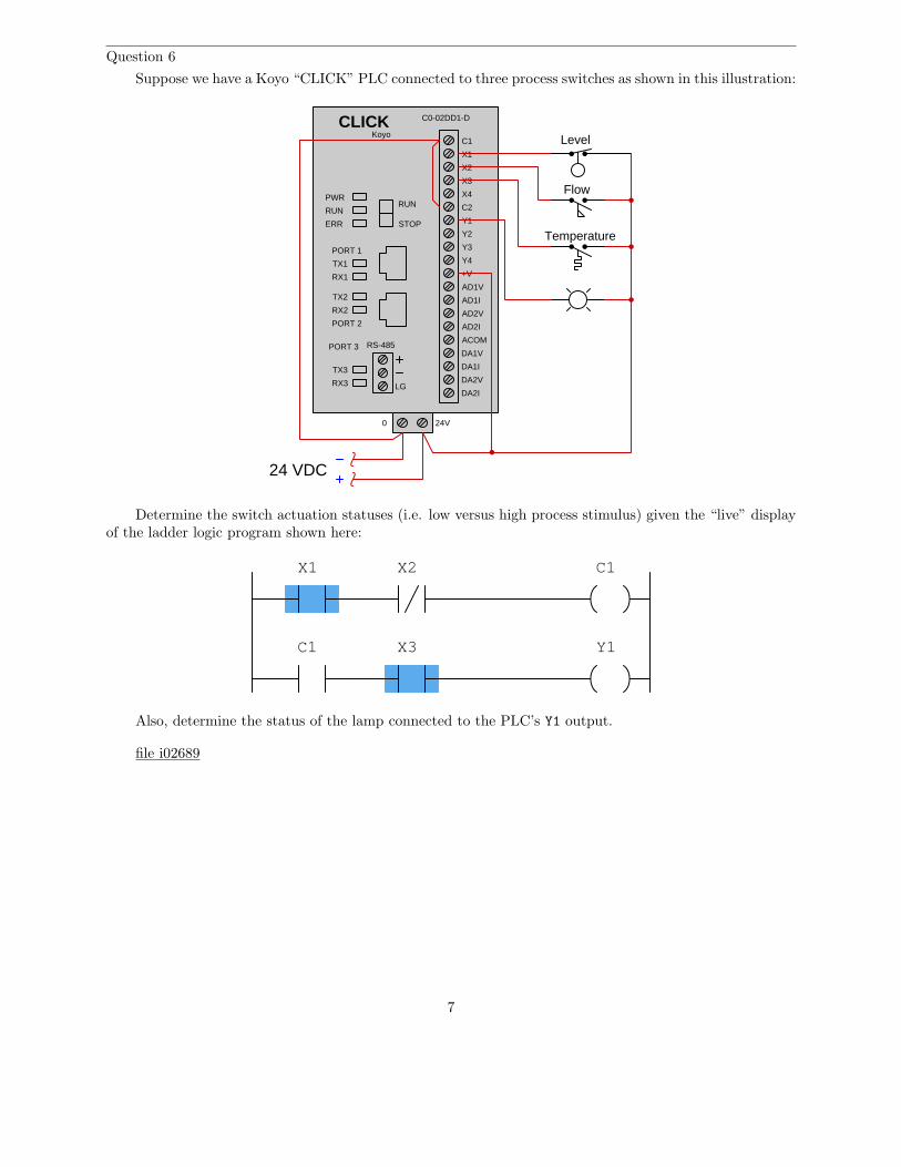
Question 6
Suppose we have a Koyo “CLICK” PLC connected to three process switches as shown in this illustration:
RS-485
LG
C1
X1
AD1V
AD1I
AD2V
AD2I
ACOM
DA1V
DA1I
DA2V
DA2I
CLICK
X2
X3
X4
C2
Y1
Y2
Y3
Y4
+V
C0-02DD1-D
Koyo
PWR
RUN
ERR
TX1
RX1
TX2
RX2
RUN
STOP
PORT 1
PORT 2
TX3
RX3
PORT 3
0 24V
24 VDC
Flow
Temperature
Level
Determine the switch actuation statuses (i.e. low versus high process stimulus) given the “live” displayof the ladder logic program shown here:
X1 X2
X3 Y1
C1
C1
Also, determine the status of the lamp connected to the PLC’s Y1 output.
file i02689
7
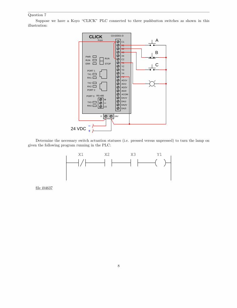
Question 7
Suppose we have a Koyo “CLICK” PLC connected to three pushbutton switches as shown in thisillustration:
RS-485
LG
C1
X1
AD1V
AD1I
AD2V
AD2I
ACOM
DA1V
DA1I
DA2V
DA2I
CLICK
X2
X3
X4
C2
Y1
Y2
Y3
Y4
+V
C0-02DD1-D
Koyo
PWR
RUN
ERR
TX1
RX1
TX2
RX2
RUN
STOP
PORT 1
PORT 2
TX3
RX3
PORT 3
0 24V
24 VDC
A
B
C
Determine the necessary switch actuation statuses (i.e. pressed versus unpressed) to turn the lamp ongiven the following program running in the PLC:
X1 X2 X3 Y1
file i04637
8
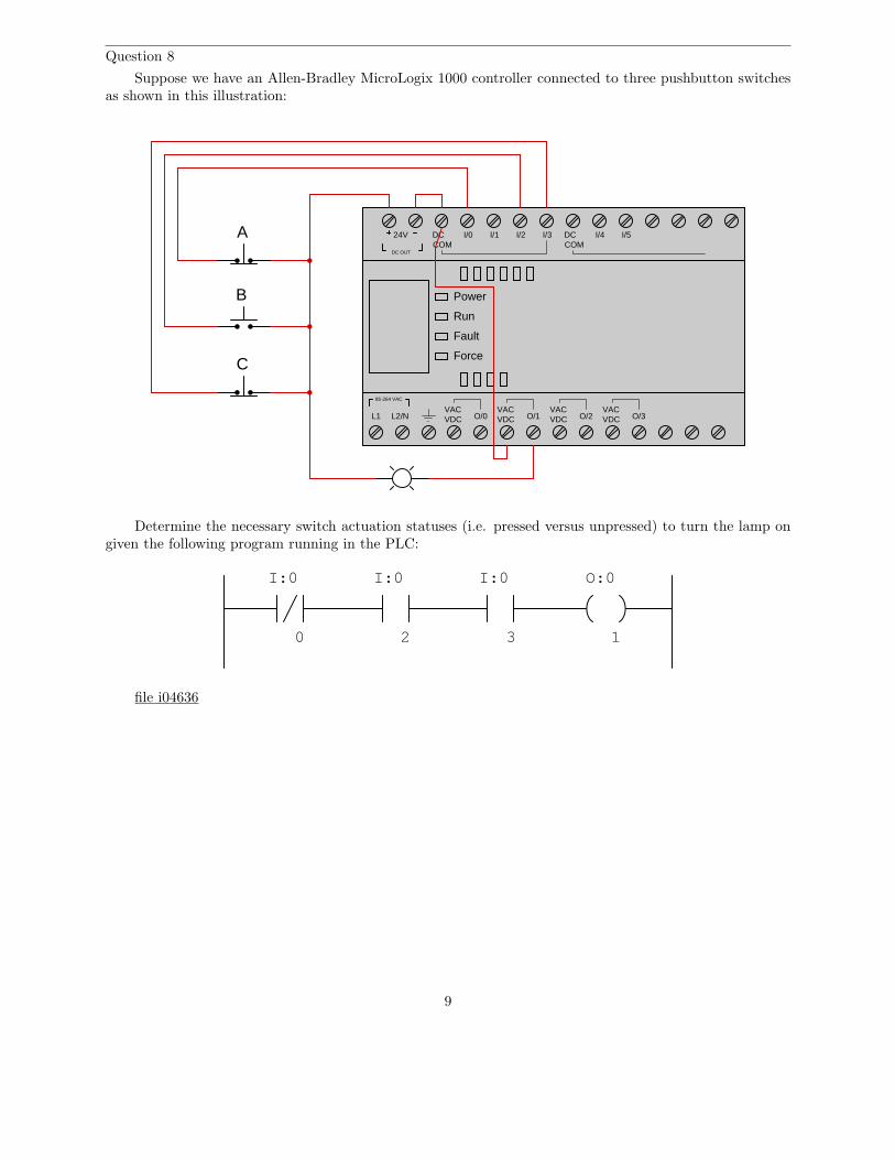
Question 8
Suppose we have an Allen-Bradley MicroLogix 1000 controller connected to three pushbutton switchesas shown in this illustration:
Power
Run
Fault
Force
L1 L2/NVACVDC O/0
VACVDC
VACVDC
VACVDCO/1 O/2 O/3
85-264 VAC
DC OUT
24V DCCOM
I/0 I/1 I/2 I/3 DCCOM
I/4 I/5A
B
C
Determine the necessary switch actuation statuses (i.e. pressed versus unpressed) to turn the lamp ongiven the following program running in the PLC:
I:0 O:0
30
I:0 I:0
2 1
file i04636
9
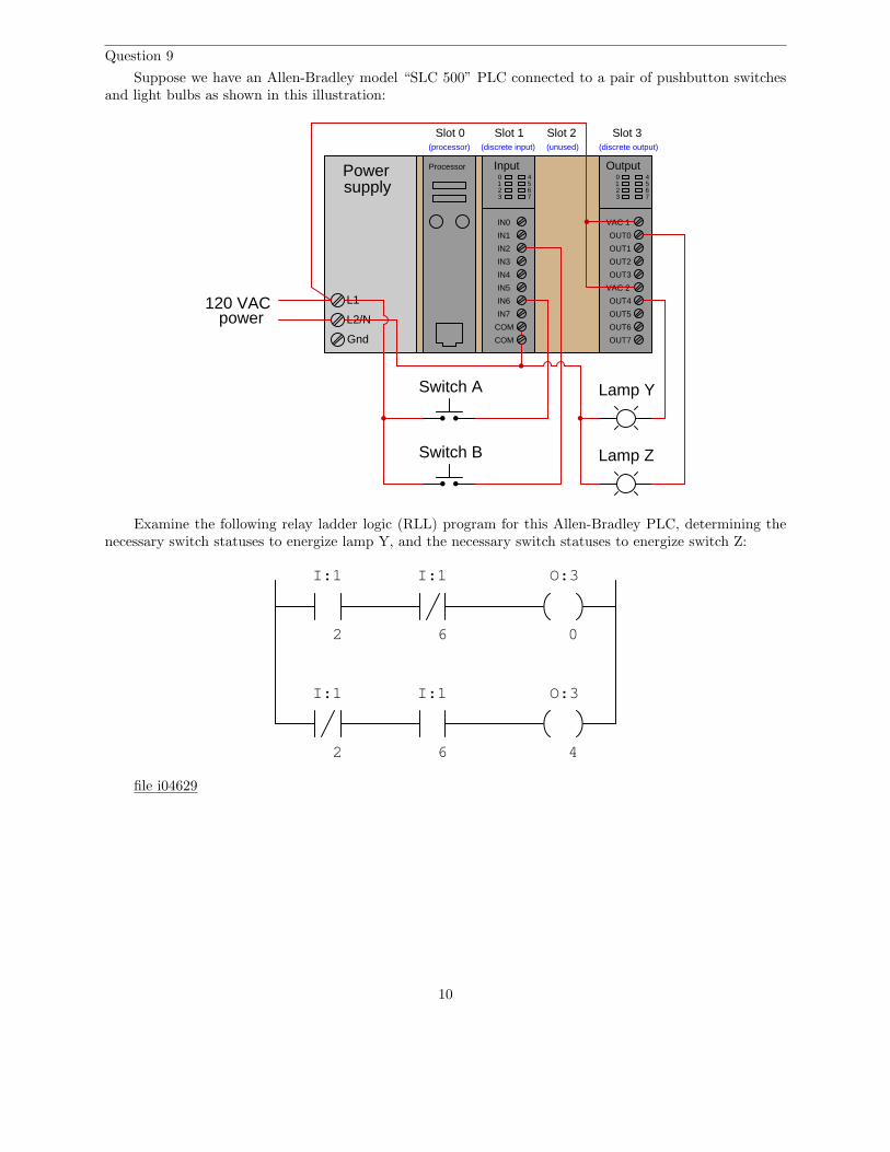
Question 9
Suppose we have an Allen-Bradley model “SLC 500” PLC connected to a pair of pushbutton switchesand light bulbs as shown in this illustration:
Powersupply
L1
Gnd
L2/N
Processor Input0123
4567
IN0
IN1
IN2
IN3
IN4
IN5
IN6
IN7
COM
COM
Slot 0 Slot 1 Slot 2 Slot 3(processor) (discrete input) (discrete output)(unused)
120 VACpower
Switch A
Switch B
VAC 1
OUT1
OUT2
OUT3
OUT4
OUT5
OUT6
OUT7
VAC 2
OUT0
Output0123
67
45
Lamp Y
Lamp Z
Examine the following relay ladder logic (RLL) program for this Allen-Bradley PLC, determining thenecessary switch statuses to energize lamp Y, and the necessary switch statuses to energize switch Z:
I:1 I:1
2 6
O:3
0
4
I:1 I:1
2 6
O:3
file i04629
10
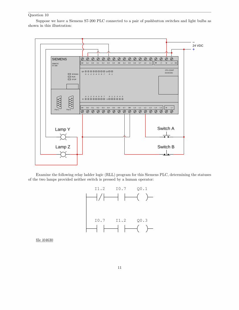
Question 10
Suppose we have a Siemens S7-200 PLC connected to a pair of pushbutton switches and light bulbs asshown in this illustration:
Switch A
Switch B
Lamp Y
Lamp Z
Port 0Port 1
SIEMENSSIMATICS7-200
RUN
STOP
SF/DIAG
Q0
I0
.0 .1 .2 .3 .4 .5 .6 .7
I1
.0 .1 .2 .3 .4 .5
.0 .1 .2 .3 .4 .5 .6 .7
Q1
.0 .1
CPU 224XP
DC/DC/DC
M L+ DC1M 1L+ 0.0 0.1 0.2 0.3 0.4 0.5 0.62M 2L+ 0.7 1.0 1.1
M L+1M 0.0 0.1 0.2 0.3 0.4 0.5 0.6 0.7 2M 1.0 1.1 1.2 1.3 1.4 1.5
24 VDC
Examine the following relay ladder logic (RLL) program for this Siemens PLC, determining the statusesof the two lamps provided neither switch is pressed by a human operator:
I0.7I1.2
I0.7 I1.2
Q0.1
Q0.3
file i04630
11
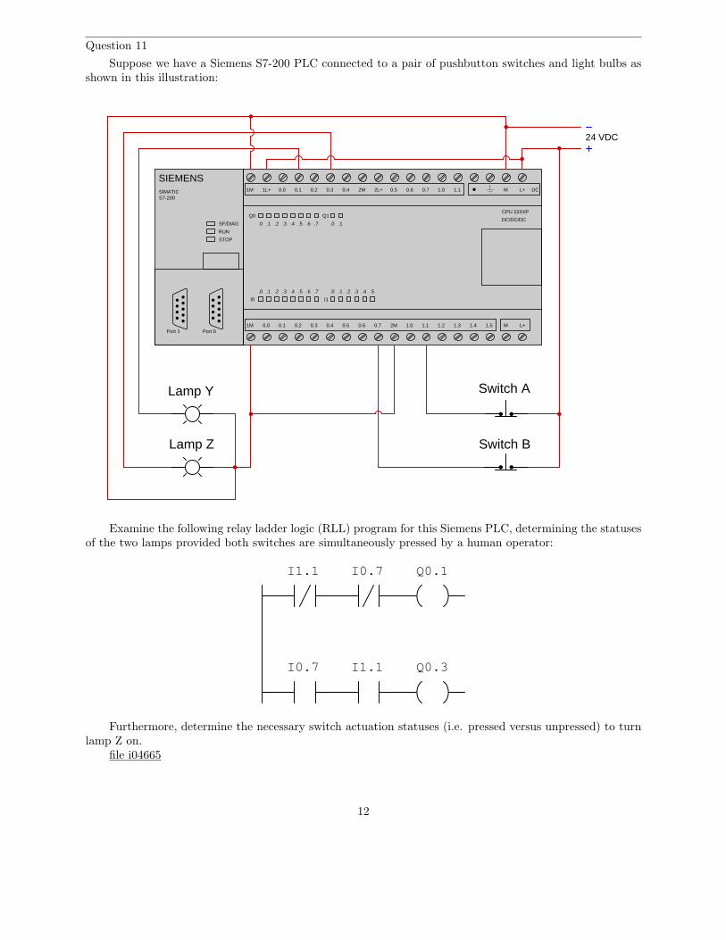
Question 11
Suppose we have a Siemens S7-200 PLC connected to a pair of pushbutton switches and light bulbs asshown in this illustration:
Switch A
Switch B
Lamp Y
Lamp Z
Port 0Port 1
SIEMENSSIMATICS7-200
RUN
STOP
SF/DIAG
Q0
I0
.0 .1 .2 .3 .4 .5 .6 .7
I1
.0 .1 .2 .3 .4 .5
.0 .1 .2 .3 .4 .5 .6 .7
Q1
.0 .1
CPU 224XP
DC/DC/DC
M L+ DC1M 1L+ 0.0 0.1 0.2 0.3 0.4 0.5 0.62M 2L+ 0.7 1.0 1.1
M L+1M 0.0 0.1 0.2 0.3 0.4 0.5 0.6 0.7 2M 1.0 1.1 1.2 1.3 1.4 1.5
24 VDC
Examine the following relay ladder logic (RLL) program for this Siemens PLC, determining the statusesof the two lamps provided both switches are simultaneously pressed by a human operator:
I0.7
I0.7
Q0.1
Q0.3I1.1
I1.1
Furthermore, determine the necessary switch actuation statuses (i.e. pressed versus unpressed) to turnlamp Z on.
file i04665
12
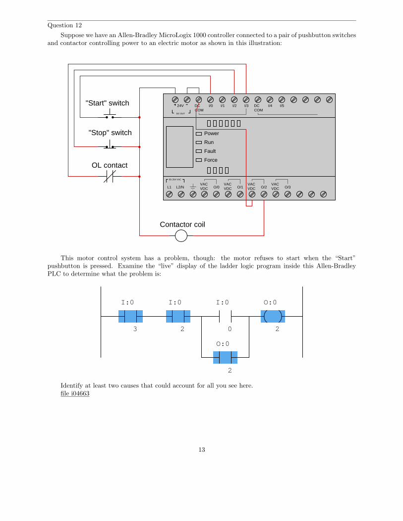
Question 12
Suppose we have an Allen-Bradley MicroLogix 1000 controller connected to a pair of pushbutton switchesand contactor controlling power to an electric motor as shown in this illustration:
Power
Run
Fault
Force
L1 L2/NVACVDC O/0
VACVDC
VACVDC
VACVDCO/1 O/2 O/3
85-264 VAC
DC OUT
24V DCCOM
I/0 I/1 I/2 I/3 DCCOM
I/4 I/5
OL contact
"Stop" switch
"Start" switch
Contactor coil
This motor control system has a problem, though: the motor refuses to start when the “Start”pushbutton is pressed. Examine the “live” display of the ladder logic program inside this Allen-BradleyPLC to determine what the problem is:
I:0 O:0
3 20
I:0 I:0
2
O:0
2
Identify at least two causes that could account for all you see here.file i04663
13
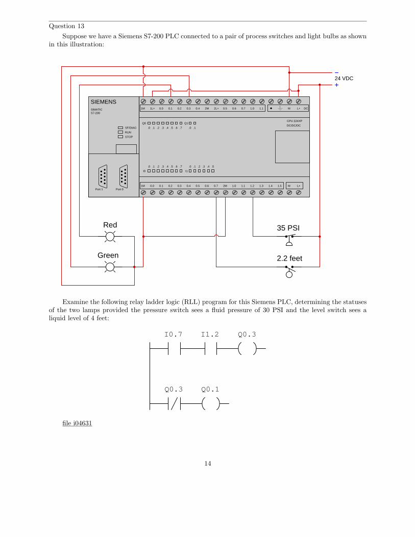
Question 13
Suppose we have a Siemens S7-200 PLC connected to a pair of process switches and light bulbs as shownin this illustration:
Port 0Port 1
SIEMENSSIMATICS7-200
RUN
STOP
SF/DIAG
Q0
I0
.0 .1 .2 .3 .4 .5 .6 .7
I1
.0 .1 .2 .3 .4 .5
.0 .1 .2 .3 .4 .5 .6 .7
Q1
.0 .1
CPU 224XP
DC/DC/DC
M L+ DC1M 1L+ 0.0 0.1 0.2 0.3 0.4 0.5 0.62M 2L+ 0.7 1.0 1.1
M L+1M 0.0 0.1 0.2 0.3 0.4 0.5 0.6 0.7 2M 1.0 1.1 1.2 1.3 1.4 1.5
24 VDC
35 PSI
2.2 feet
Red
Green
Examine the following relay ladder logic (RLL) program for this Siemens PLC, determining the statusesof the two lamps provided the pressure switch sees a fluid pressure of 30 PSI and the level switch sees aliquid level of 4 feet:
I0.7 I1.2
Q0.1
Q0.3
Q0.3
file i04631
14
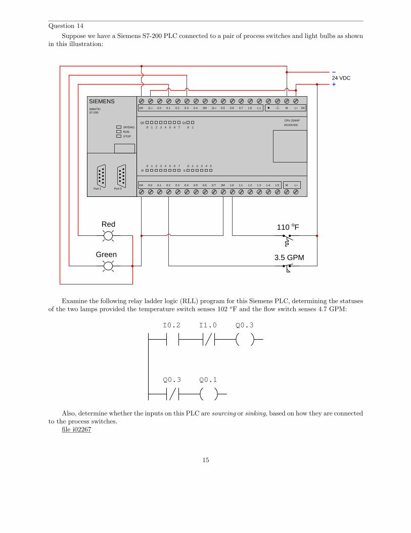
Question 14
Suppose we have a Siemens S7-200 PLC connected to a pair of process switches and light bulbs as shownin this illustration:
Port 0Port 1
SIEMENSSIMATICS7-200
RUN
STOP
SF/DIAG
Q0
I0
.0 .1 .2 .3 .4 .5 .6 .7
I1
.0 .1 .2 .3 .4 .5
.0 .1 .2 .3 .4 .5 .6 .7
Q1
.0 .1
CPU 224XP
DC/DC/DC
M L+ DC1M 1L+ 0.0 0.1 0.2 0.3 0.4 0.5 0.62M 2L+ 0.7 1.0 1.1
M L+1M 0.0 0.1 0.2 0.3 0.4 0.5 0.6 0.7 2M 1.0 1.1 1.2 1.3 1.4 1.5
24 VDC
Red
Green
110 oF
3.5 GPM
Examine the following relay ladder logic (RLL) program for this Siemens PLC, determining the statusesof the two lamps provided the temperature switch senses 102 oF and the flow switch senses 4.7 GPM:
Q0.1
Q0.3
Q0.3
I1.0I0.2
Also, determine whether the inputs on this PLC are sourcing or sinking, based on how they are connectedto the process switches.
file i02267
15
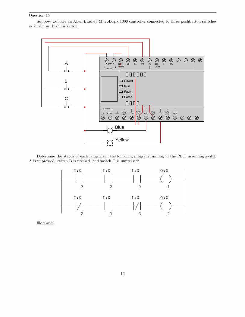
Question 15
Suppose we have an Allen-Bradley MicroLogix 1000 controller connected to three pushbutton switchesas shown in this illustration:
Power
Run
Fault
Force
L1 L2/NVACVDC O/0
VACVDC
VACVDC
VACVDCO/1 O/2 O/3
85-264 VAC
DC OUT
24V DCCOM
I/0 I/1 I/2 I/3 DCCOM
I/4 I/5A
B
C
Blue
Yellow
Determine the status of each lamp given the following program running in the PLC, assuming switchA is unpressed, switch B is pressed, and switch C is unpressed:
I:0 O:0
3 0
I:0 I:0
2
3 202
1
I:0 I:0 I:0 O:0
file i04632
16

Question 16
Suppose we have an Allen-Bradley MicroLogix 1000 controller connected to three pushbutton switchesas shown in this illustration:
Power
Run
Fault
Force
L1 L2/NVACVDC O/0
VACVDC
VACVDC
VACVDCO/1 O/2 O/3
85-264 VAC
DC OUT
24V DCCOM
I/0 I/1 I/2 I/3 DCCOM
I/4 I/5A
B
C
Blue
Yellow
Determine the necessary switch actuation statuses (i.e. pressed versus unpressed) to turn the blue lampon, given the following program running in the PLC:
I:0 O:0
3 0
I:0 I:0
2
3 202
1
I:0 I:0 I:0 O:0
file i04633
17
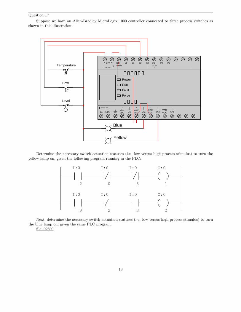
Question 17
Suppose we have an Allen-Bradley MicroLogix 1000 controller connected to three process switches asshown in this illustration:
Power
Run
Fault
Force
L1 L2/NVACVDC O/0
VACVDC
VACVDC
VACVDCO/1 O/2 O/3
85-264 VAC
DC OUT
24V DCCOM
I/0 I/1 I/2 I/3 DCCOM
I/4 I/5
Blue
Yellow
Temperature
Flow
Level
Determine the necessary switch actuation statuses (i.e. low versus high process stimulus) to turn theyellow lamp on, given the following program running in the PLC:
I:0 O:0
30
I:0 I:0
2
3 20 2
1
I:0 I:0 I:0 O:0
Next, determine the necessary switch actuation statuses (i.e. low versus high process stimulus) to turnthe blue lamp on, given the same PLC program.
file i02600
18
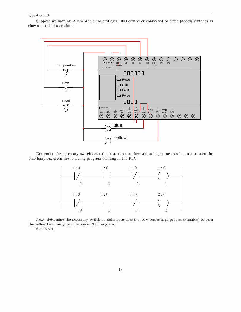
Question 18
Suppose we have an Allen-Bradley MicroLogix 1000 controller connected to three process switches asshown in this illustration:
Power
Run
Fault
Force
L1 L2/NVACVDC O/0
VACVDC
VACVDC
VACVDCO/1 O/2 O/3
85-264 VAC
DC OUT
24V DCCOM
I/0 I/1 I/2 I/3 DCCOM
I/4 I/5
Blue
Yellow
Temperature
Flow
Level
Determine the necessary switch actuation statuses (i.e. low versus high process stimulus) to turn theblue lamp on, given the following program running in the PLC:
I:0 O:0
3 0
I:0I:0
2
3 20 2
1
I:0 I:0 I:0 O:0
Next, determine the necessary switch actuation statuses (i.e. low versus high process stimulus) to turnthe yellow lamp on, given the same PLC program.
file i02601
19
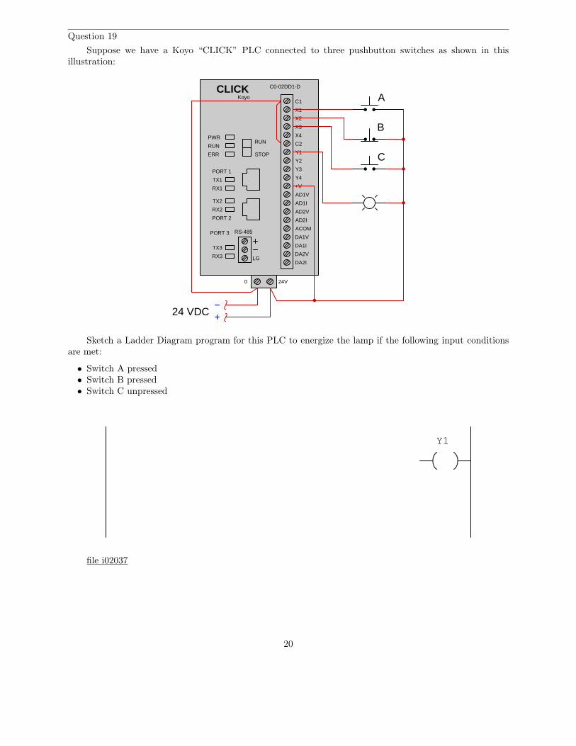
Question 19
Suppose we have a Koyo “CLICK” PLC connected to three pushbutton switches as shown in thisillustration:
RS-485
LG
C1
X1
AD1V
AD1I
AD2V
AD2I
ACOM
DA1V
DA1I
DA2V
DA2I
CLICK
X2
X3
X4
C2
Y1
Y2
Y3
Y4
+V
C0-02DD1-D
Koyo
PWR
RUN
ERR
TX1
RX1
TX2
RX2
RUN
STOP
PORT 1
PORT 2
TX3
RX3
PORT 3
0 24V
24 VDC
A
B
C
Sketch a Ladder Diagram program for this PLC to energize the lamp if the following input conditionsare met:
• Switch A pressed• Switch B pressed• Switch C unpressed
Y1
file i02037
20
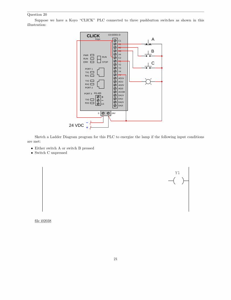
Question 20
Suppose we have a Koyo “CLICK” PLC connected to three pushbutton switches as shown in thisillustration:
RS-485
LG
C1
X1
AD1V
AD1I
AD2V
AD2I
ACOM
DA1V
DA1I
DA2V
DA2I
CLICK
X2
X3
X4
C2
Y1
Y2
Y3
Y4
+V
C0-02DD1-D
Koyo
PWR
RUN
ERR
TX1
RX1
TX2
RX2
RUN
STOP
PORT 1
PORT 2
TX3
RX3
PORT 3
0 24V
24 VDC
A
B
C
Sketch a Ladder Diagram program for this PLC to energize the lamp if the following input conditionsare met:
• Either switch A or switch B pressed• Switch C unpressed
Y1
file i02038
21
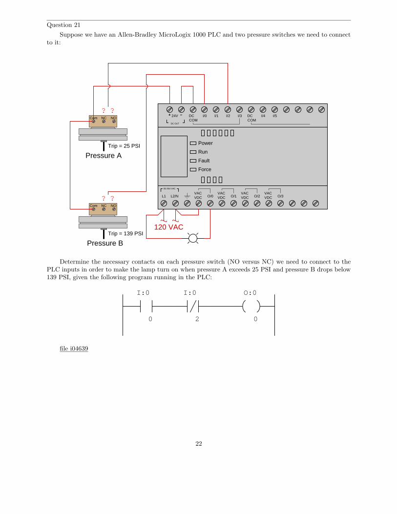
Question 21
Suppose we have an Allen-Bradley MicroLogix 1000 PLC and two pressure switches we need to connectto it:
Power
Run
Fault
Force
L1 L2/NVACVDC O/0
VACVDC
VACVDC
VACVDCO/1 O/2 O/3
85-264 VAC
DC OUT
24V DCCOM
I/0 I/1 I/2 I/3 DCCOM
I/4 I/5
Com NC NO
Com NC NO
??
? ?
120 VAC
Pressure A
Pressure B
Trip = 25 PSI
Trip = 139 PSI
Determine the necessary contacts on each pressure switch (NO versus NC) we need to connect to thePLC inputs in order to make the lamp turn on when pressure A exceeds 25 PSI and pressure B drops below139 PSI, given the following program running in the PLC:
0 2
O:0
0
I:0 I:0
file i04639
22
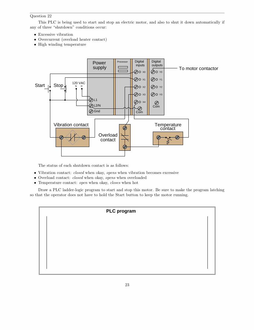
Question 22
This PLC is being used to start and stop an electric motor, and also to shut it down automatically ifany of three “shutdown” conditions occur:
• Excessive vibration• Overcurrent (overload heater contact)• High winding temperature
Powersupply
L1
Gnd
Processor Digitalinputs
Digitaloutputs
L2/N
Com
X0
X1
X2
X3
Com
Y0
Y1
Y2
Y3
Overloadcontact
Temperaturecontact
Vibration contact
To motor contactor
120 VAC
X4
Start Stop HN
The status of each shutdown contact is as follows:
• Vibration contact: closed when okay, opens when vibration becomes excessive• Overload contact: closed when okay, opens when overloaded• Temperature contact: open when okay, closes when hot
Draw a PLC ladder-logic program to start and stop this motor. Be sure to make the program latchingso that the operator does not have to hold the Start button to keep the motor running.
PLC program
23
file i03847
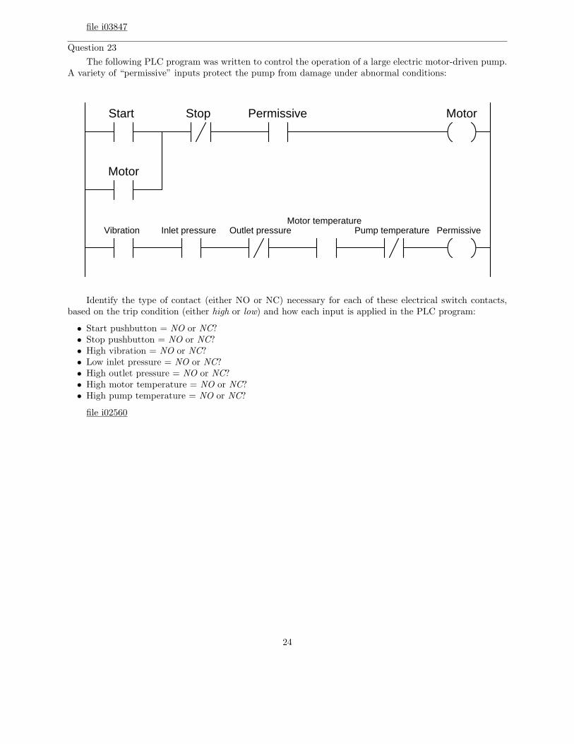
Question 23
The following PLC program was written to control the operation of a large electric motor-driven pump.A variety of “permissive” inputs protect the pump from damage under abnormal conditions:
Motor
Motor
Start Stop Permissive
PermissiveVibration Inlet pressure Outlet pressureMotor temperature
Pump temperature
Identify the type of contact (either NO or NC) necessary for each of these electrical switch contacts,based on the trip condition (either high or low) and how each input is applied in the PLC program:
• Start pushbutton = NO or NC?• Stop pushbutton = NO or NC?• High vibration = NO or NC?• Low inlet pressure = NO or NC?• High outlet pressure = NO or NC?• High motor temperature = NO or NC?• High pump temperature = NO or NC?
file i02560
24
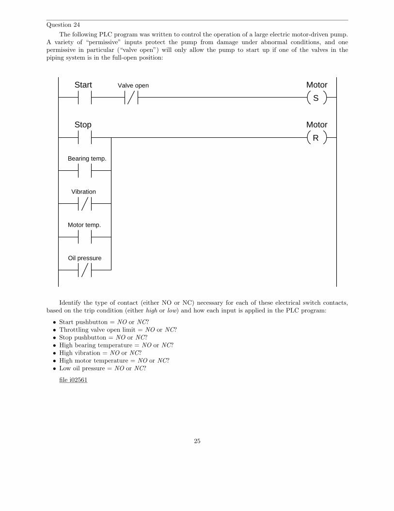
Question 24
The following PLC program was written to control the operation of a large electric motor-driven pump.A variety of “permissive” inputs protect the pump from damage under abnormal conditions, and onepermissive in particular (“valve open”) will only allow the pump to start up if one of the valves in thepiping system is in the full-open position:
MotorStart
Stop
Vibration
S
R
Motor
Bearing temp.
Oil pressure
Motor temp.
Valve open
Identify the type of contact (either NO or NC) necessary for each of these electrical switch contacts,based on the trip condition (either high or low) and how each input is applied in the PLC program:
• Start pushbutton = NO or NC?• Throttling valve open limit = NO or NC?• Stop pushbutton = NO or NC?• High bearing temperature = NO or NC?• High vibration = NO or NC?• High motor temperature = NO or NC?• Low oil pressure = NO or NC?
file i02561
25
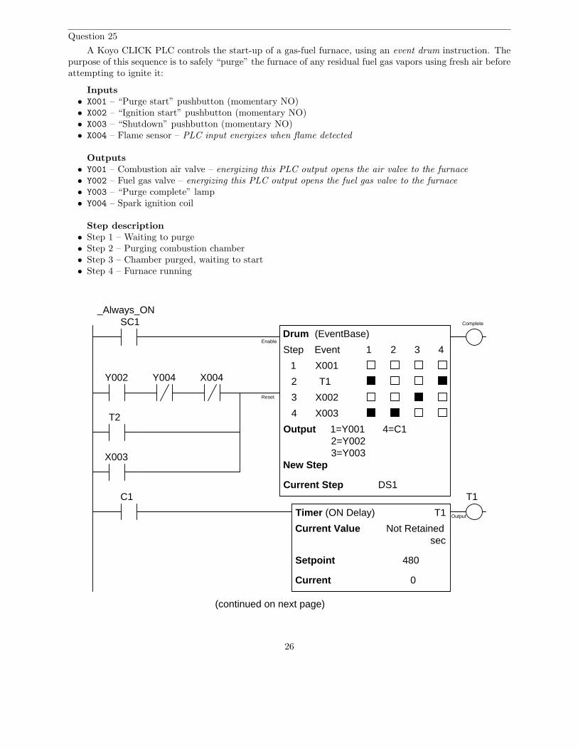
Question 25
A Koyo CLICK PLC controls the start-up of a gas-fuel furnace, using an event drum instruction. Thepurpose of this sequence is to safely “purge” the furnace of any residual fuel gas vapors using fresh air beforeattempting to ignite it:
Inputs• X001 – “Purge start” pushbutton (momentary NO)• X002 – “Ignition start” pushbutton (momentary NO)• X003 – “Shutdown” pushbutton (momentary NO)• X004 – Flame sensor – PLC input energizes when flame detected
Outputs• Y001 – Combustion air valve – energizing this PLC output opens the air valve to the furnace
• Y002 – Fuel gas valve – energizing this PLC output opens the fuel gas valve to the furnace
• Y003 – “Purge complete” lamp• Y004 – Spark ignition coil
Step description• Step 1 – Waiting to purge• Step 2 – Purging combustion chamber• Step 3 – Chamber purged, waiting to start• Step 4 – Furnace running
Drum
Step 1 2 3
1
2
3
Output
Complete
1=Y0012=Y0023=Y003
New Step
Current Step DS1
(EventBase)
Event 4
Timer (ON Delay) T1
Current Value Not Retainedsec
Setpoint
Current
T1
Output
SC1_Always_ON
C1
4=C1
480
0
Enable
Reset
4
X001
T1
T2
X002
X003
X003
Y002 Y004 X004
(continued on next page)
26
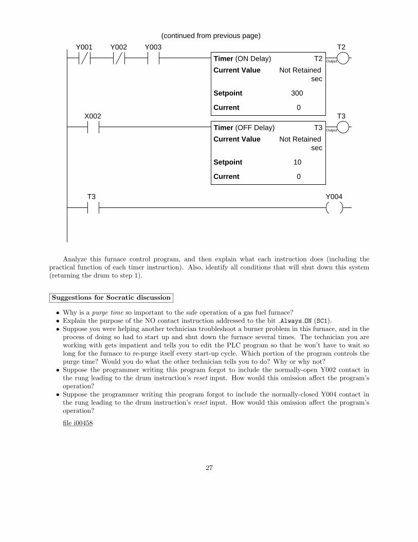
Timer (ON Delay)
Current Value Not Retainedsec
Setpoint
Current
Output
0
T2
T2Y001 Y002 Y003
300
Current Value Not Retainedsec
Setpoint
Current
Output
0
Timer (OFF Delay) T3
T3X002
10
Y004T3
(continued from previous page)
Analyze this furnace control program, and then explain what each instruction does (including thepractical function of each timer instruction). Also, identify all conditions that will shut down this system(returning the drum to step 1).
Suggestions for Socratic discussion
• Why is a purge time so important to the safe operation of a gas fuel furnace?• Explain the purpose of the NO contact instruction addressed to the bit Always ON (SC1).• Suppose you were helping another technician troubleshoot a burner problem in this furnace, and in the
process of doing so had to start up and shut down the furnace several times. The technician you areworking with gets impatient and tells you to edit the PLC program so that he won’t have to wait solong for the furnace to re-purge itself every start-up cycle. Which portion of the program controls thepurge time? Would you do what the other technician tells you to do? Why or why not?
• Suppose the programmer writing this program forgot to include the normally-open Y002 contact inthe rung leading to the drum instruction’s reset input. How would this omission affect the program’soperation?
• Suppose the programmer writing this program forgot to include the normally-closed Y004 contact inthe rung leading to the drum instruction’s reset input. How would this omission affect the program’soperation?
file i00458
27
Answers
Answer 1
Switch statuses:
• Switch A = pressed• Switch B = released• Switch C = released
The lamp will be de-energized.
Answer 2
High pressure and low flow and low temperature.
The lamp will be de-energized.
Answer 3
High pressure and low flow and high temperature.
The lamp will be de-energized.
Answer 4
High pressure and high flow and low temperature.
The lamp will be energized.
Answer 5
Low level and low flow and low temperature.
The lamp will be energized.
Answer 6
Low level and high flow and high temperature.
The lamp will be de-energized.
Answer 7
Necessary switch statuses:
• Switch A = released• Switch B = released• Switch C = pressed
Answer 8
Necessary switch statuses:
• Switch A = pressed• Switch B = pressed• Switch C = released
Answer 9
To energize lamp Z: press switch B, release switch A.
To energize lamp Y: press switch A, release switch B.
28
Answer 10
Output Q0.1 will activate to energize lamp Y, but the other output (and lamp) will remain off.
Answer 11
Output Q0.1 will activate to energize lamp Y, but the other output (and lamp) will remain off.
To energize lamp Z, you must release (unpress) both switches.
Answer 12
• Contactor coil failed open• Wire connecting contactor coil to O:0/2 failed open• Wire connecting VAC-VDC terminal to DC COM terminal failed open• Wire connecting input switch “commons” to contactor coil failed open• Output channel O:0/2 defective on the PLC• 24 VDC power supply in the PLC is insufficient to power the contactor’s coil
Answer 13
Green lamp is on, red lamp is off.
Answer 14
Green lamp is off, red lamp is on. The PLC inputs are configured here to sink current.
Answer 15
The blue lamp will be off and the yellow lamp will be on.
Answer 16
Switch A = pressed
Switch B = released
Switch C = pressed
Answer 17
Low temperature and low flow and low level are required to energize the yellow lamp.
High temperature and high flow and high level are required to energize the blue lamp.
Answer 18
High temperature and low flow and high level are required to energize the blue lamp.
Low temperature and high flow and high level are required to energize the yellow lamp.
29
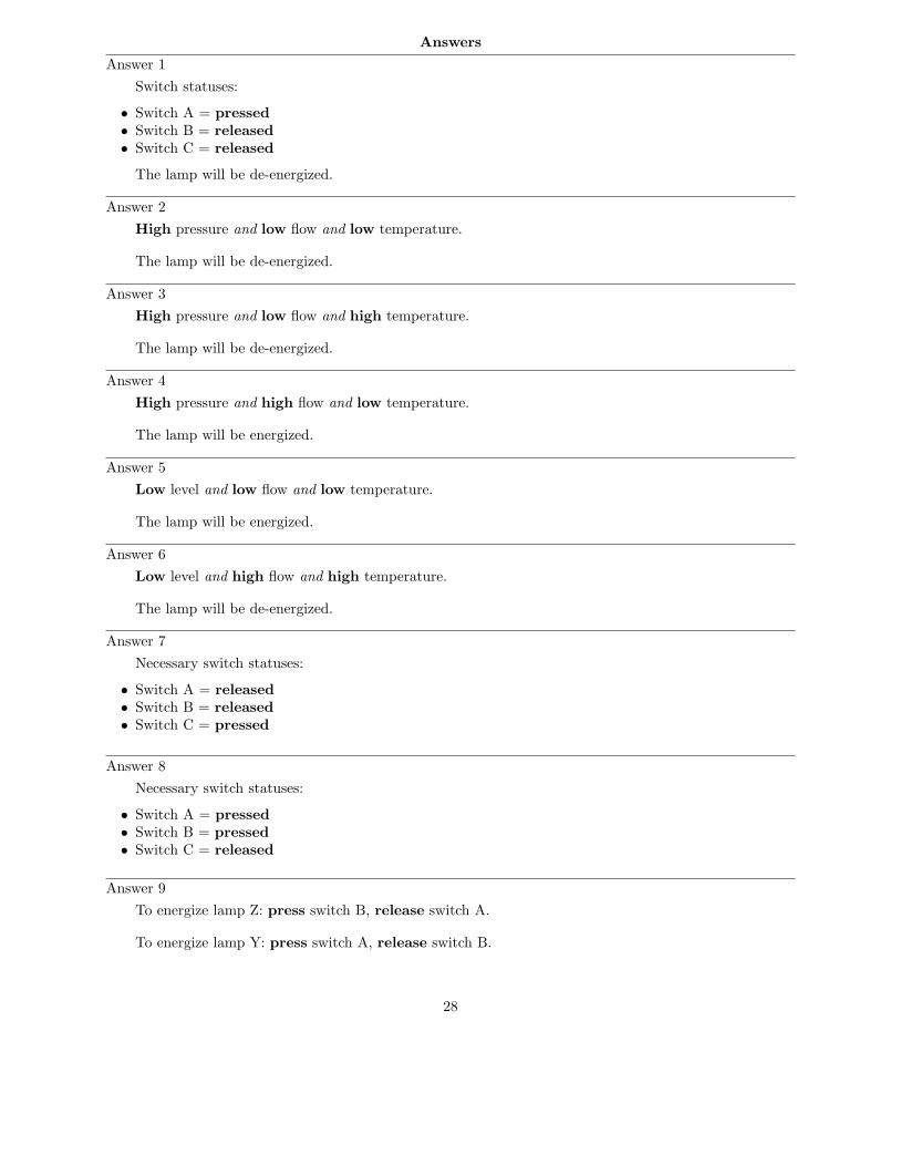
Answer 19
Y1X1 X2 X3
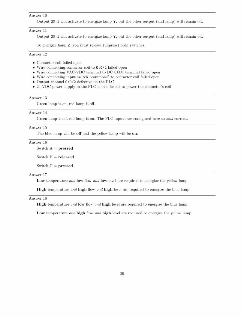
Answer 20
Y1X1
X2
X3
Answer 21
Both pressure switches need their normally-closed (NC) contact terminals connected to the respectivePLC input terminals.
30
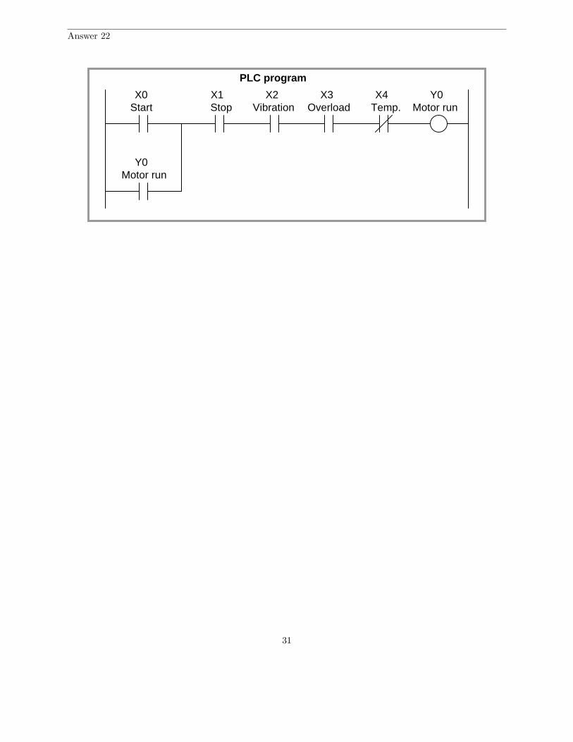
Answer 22
Start
Y0Motor run
X1Stop
X0
PLC program
X2 X3 X4 Y0Vibration Overload Motor runTemp.
31
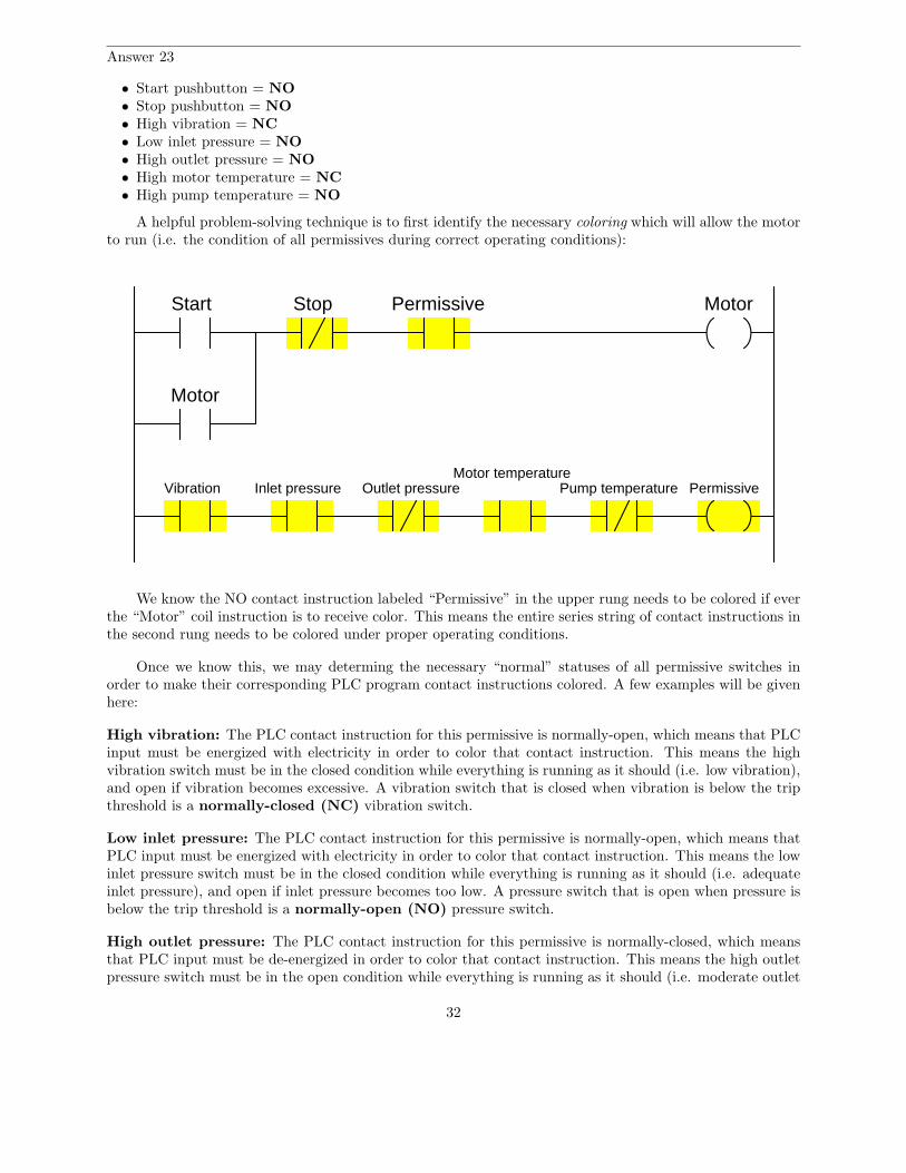
Answer 23
• Start pushbutton = NO• Stop pushbutton = NO• High vibration = NC• Low inlet pressure = NO• High outlet pressure = NO• High motor temperature = NC• High pump temperature = NO
A helpful problem-solving technique is to first identify the necessary coloring which will allow the motorto run (i.e. the condition of all permissives during correct operating conditions):
Motor
Motor
Start Stop Permissive
PermissiveVibration Inlet pressure Outlet pressureMotor temperature
Pump temperature
We know the NO contact instruction labeled “Permissive” in the upper rung needs to be colored if everthe “Motor” coil instruction is to receive color. This means the entire series string of contact instructions inthe second rung needs to be colored under proper operating conditions.
Once we know this, we may determing the necessary “normal” statuses of all permissive switches inorder to make their corresponding PLC program contact instructions colored. A few examples will be givenhere:
High vibration: The PLC contact instruction for this permissive is normally-open, which means that PLCinput must be energized with electricity in order to color that contact instruction. This means the highvibration switch must be in the closed condition while everything is running as it should (i.e. low vibration),and open if vibration becomes excessive. A vibration switch that is closed when vibration is below the tripthreshold is a normally-closed (NC) vibration switch.
Low inlet pressure: The PLC contact instruction for this permissive is normally-open, which means thatPLC input must be energized with electricity in order to color that contact instruction. This means the lowinlet pressure switch must be in the closed condition while everything is running as it should (i.e. adequateinlet pressure), and open if inlet pressure becomes too low. A pressure switch that is open when pressure isbelow the trip threshold is a normally-open (NO) pressure switch.
High outlet pressure: The PLC contact instruction for this permissive is normally-closed, which meansthat PLC input must be de-energized in order to color that contact instruction. This means the high outletpressure switch must be in the open condition while everything is running as it should (i.e. moderate outlet
32

pressure), and close if outlet pressure becomes excessive. A pressure switch that is open when pressure isbelow the trip threshold is a normally-open (NO) pressure switch.
33
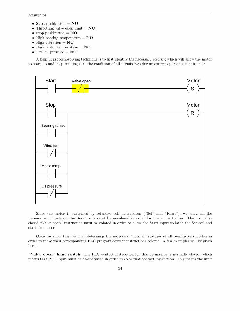
Answer 24
• Start pushbutton = NO• Throttling valve open limit = NC• Stop pushbutton = NO• High bearing temperature = NO• High vibration = NC• High motor temperature = NO• Low oil pressure = NO
A helpful problem-solving technique is to first identify the necessary coloring which will allow the motorto start up and keep running (i.e. the condition of all permissives during correct operating conditions):
MotorStart
Stop
Vibration
S
R
Motor
Bearing temp.
Oil pressure
Motor temp.
Valve open
Since the motor is controlled by retentive coil instructions (“Set” and “Reset”), we know all thepermissive contacts on the Reset rung must be uncolored in order for the motor to run. The normally-closed “Valve open” instruction must be colored in order to allow the Start input to latch the Set coil andstart the motor.
Once we know this, we may determing the necessary “normal” statuses of all permissive switches inorder to make their corresponding PLC program contact instructions colored. A few examples will be givenhere:
“Valve open” limit switch: The PLC contact instruction for this permissive is normally-closed, whichmeans that PLC input must be de-energized in order to color that contact instruction. This means the limit
34
switch must be in the open condition when the valve mechanism moves into the switch’s sensing range (inthe fully-open position), and close when the valve mechanism moves away from the switch. A limit switchthat is closed with nothing near it is a normally-closed (NC) limit switch.
Low oil pressure: The PLC contact instruction for this permissive is normally-closed, which means thatPLC input must be energized with electricity in order to maintain that contact instruction in an uncoloredstate. This means the low oil pressure switch must be in the closed condition while everything is runningas it should (i.e. adequate oil pressure), and open if oil pressure becomes too low. A pressure switch that isopen when pressure is below the trip threshold is a normally-open (NO) pressure switch.
High bearing temperature: The PLC contact instruction for this permissive is normally-open, whichmeans that PLC input must be de-energized in order to maintain that contact instruction in an uncoloredstate. This means the high bearing temperature switch must be in the open condition while everythingis running as it should (i.e. low bearing temperature), and close if temperature becomes excessive. Atemperature switch that is open when temperature is below the trip threshold is a normally-open (NO)temperature switch.
Answer 25
35


![The Synthesis and Analysis of Stochastic Switching Circuits · 2017-02-27 · ern digital circuit design [12]. Later, deterministic switches were replaced with probabilistic switches](https://img.pdfslide.us/doc/110x75/5f419129ab53844b3458809a/the-synthesis-and-analysis-of-stochastic-switching-circuits-2017-02-27-ern-digital.jpg)