Embed Size (px)
Citation preview

Process Safety Aspects in
Water-Gas-Shift (WGS) Catalytic Membrane
Reactors Used for Pure Hydrogen Production
Center for Inorganic Membrane Studies (CIMS)
Worcester Polytechnic Institute
Department of Chemical Engineering
Reyyan Koc, Nikolaos K. Kazantzis and Yi Hua Ma
Mary Kay O’Connor Process Safety Center
International Symposium
October 26-28, 2010 / Texas

Outline
• Introduction
– Pd-Based Membrane Reactor
– H2 Transport Through Pd-Based Membrane
– Pd/Alloy Membrane Reactors in IGCC Plants
• Safety Analysis for Pd/Alloy Membrane Reactors
– Objective
– Modeling Results
[Tfeed, Wcatalyst, H2O:CO Ratio, Driving for H2 permeation (∆PH2)]
– Safety Aspects – HAZOP
[Feed flow rate, Reaction side pressure, Impurities]
• Conclusions
2

Pd-Based Membrane Reactor
3
CO + H2O ↔ CO2 + H2 ΔH298K = - 40.1kJ/mol
½'' OD ×2.5'' Long
4 in2 (25 cm2)
WPI –Pd/Alloy Membranes
Pd supported on porous Inconel
(media grade 0.1 µm)
Prepared by Electroless Plating
Excellent long term H2/He selectivity
GE Syngas
Retentate: Mostly CO2 + H2O
H2r2
r1
1 2 3
4
1 & 3. Inert packing
2. Reaction /Shell side
4. Permeate/Tube side
Pd-based membrane
HT WGS catalyst
Applications of catalytic membrane reactors to refinery products [10] :
• Dehydrogenation & hydrogenation reactions
• Conversion of remote natural gas to syngas and liquid fuels
• Steam reforming
• Water gas shift reaction
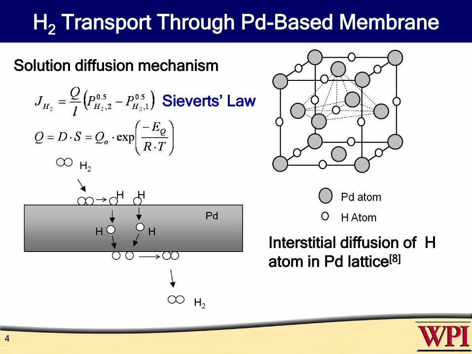
H2 Transport Through Pd-Based Membrane
4
Interstitial diffusion of H
atom in Pd lattice[8]
Solution diffusion mechanism
Sieverts’ Law
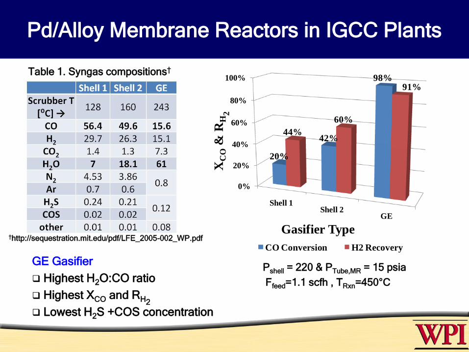
Pd/Alloy Membrane Reactors in IGCC Plants
GE Gasifier
Highest H2O:CO ratio
Highest XCO and RH2
Lowest H2S +COS concentration
Table 1. Syngas compositions†
†http://sequestration.mit.edu/pdf/LFE_2005-002_WP.pdf
Pshell = 220 & PTube,MR = 15 psia
Ffeed=1.1 scfh , TRxn=450°C
0%
20%
40%
60%
80%
100%
Shell 1Shell 2
GE
20%
42%
98%
44%
60%
91%
XC
O&
RH
2Gasifier Type
CO Conversion H2 Recovery

Safety Analysis for
Pd/Alloy Membrane Reactors - Objective
6
The standard principles of Hazard and Operability (HAZOP) analysis were
followed to identify and prevent potential process risks to personnel,
environment, equipment integrity and/or the efficiency or economics of the
process [5.6].
Pshell = 220 & PTube,MR = 6 psia
FDry feed=1.1 scfh , TRxn=400°C
H2O:CO XCO
[%]
RH2
[%]
FH2Ratio
MR / PBR
MR 2 99 961.2
PBR 9 98 -
Isothermal Case:
Performance target levels: XCO = 98% & RH2 = 95%
Membrane reactor limitations:
1. Reaction side temperature:@ T≤ 300 C for Pure Pd H2 embrittlement &
@ T≥ 550 C intermetallic diffusion and permeance decline
2. Impurities : Poisoning of the Pd membrane due to H2S in the feed

Feed Temperature
7
250 300 350 400
1000
2000
3000
4000
5000
6000
20
30
40
50
60
70
80
RH2
[b]
1
2
TFeed [°C]
250 300 350 400
1000
2000
3000
4000
5000
6000
250
300
350
400
450
500
550
11 1
TMAX
Fe
ed
flo
w r
ate
[sccm
]
TFeed [°C][a]
PShell = 15 atm, PTube = 1 atm, H2O:CO = 2 and 100% ρBulk,max
TRxn,Max = 500 C &TRxn,Min = 300 C for pure Pd membranes
• Tfeed ≤ 300°C to protect the membrane, however XCO = 95% and RH2 = 89%
• The target levels of XCO = 98% and RH2 = 95% were not achieved
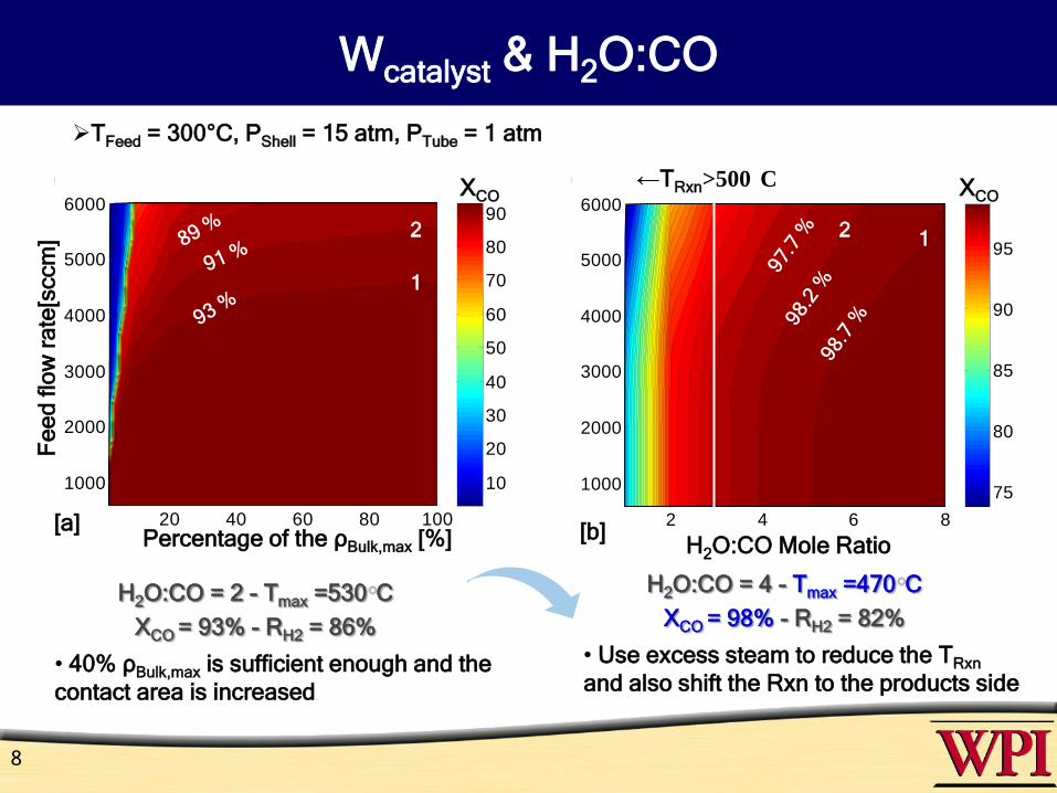
Wcatalyst & H2O:CO
8
TFeed = 300°C, PShell = 15 atm, PTube = 1 atm
• 40% ρBulk,max is sufficient enough and the
contact area is increased
• Use excess steam to reduce the TRxn
and also shift the Rxn to the products side
H2O:CO = 2 - Tmax =530 C
XCO = 93% - RH2 = 86%
H2O:CO = 4 - Tmax =470 C
XCO = 98% - RH2 = 82%
20 40 60 80 100
1000
2000
3000
4000
5000
6000
10
20
30
40
50
60
70
80
90
Fe
ed
flo
w r
ate
[sccm
]
Percentage of the ρBulk,max [%]
1
2
[a]
XCO
2 4 6 8
1000
2000
3000
4000
5000
6000
75
80
85
90
95
H2O:CO Mole Ratio
12
[b]
XCO←TRxn>500 C

Process Safety Aspects: FFeed
9
FFeedCauses Consequences Prevention & Repair
More
(Above the
nominal
level)
•Malfunction of
the flow control
instruments
•Inappropriate
adjustment
and/or failure of
the valves and
pressure
regulators
Da>1 •Hot spots
•Membrane damage
•Catalyst sintering
•Regular maintenance and
inspection of the control
instrument, valves and
pressure regulators
•A backup line before the
reactor entrance
• Fast responsive
temperature recorders and
controllers
• Relief valves
• Poisonous gas detectors
on both reaction and
permeate sides
• Regeneration / substitution
of the membrane
Da>>1 •Reduced XCO & RH2
• Decreased TRxn and variations
Less
(Below the
nominal
level)
(same causes
with More and)
•Plugging of the
lines
•Leaks on the
feed line
Da<1 Insignificant changes
Da<<1 •Decreased TRxn due to reduced
∆HRxn
•Reduced H2 production rates
• Pressure increase in the feed
line due to plugging
• Pressure decrease due to leaks
No
(no flow)
Oxidation of the membrane
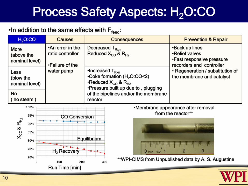
Process Safety Aspects: H2O:CO
10
H2O:CO Causes Consequences Prevention & Repair
More
(above the
nominal level)
•An error in the
ratio controller
•Failure of the
water pump
Decreased TRxn
Reduced XCO & RH2
•Back up lines
•Relief valves
•Fast responsive pressure
recorders and controller
• Regeneration / substitution of
the membrane and catalystLess
(blow the
nominal level)
•Increased TRxn
•Coke formation (H2O:CO<2)
•Reduced XCO & RH2
•Pressure built up due to , plugging
of the pipelines and/or the membrane
reactor
No
( no steam )
•In addition to the same effects with Ffeed:
70%
75%
80%
85%
90%
95%
100%
0 100 200 300
CO
Co
nve
rsio
n a
nd
H2
Re
co
ve
ry
Run Time (min)
CO Conversion
H2 Recovery
EquilibriumXC
O &
RH
2
Run Time [min]
•Membrane appearance after removal
from the reactor**
**WPI-CIMS from Unpublished data by A. S. Augustine

Increase ΔPH2 : Driving force for H2 permeation
11
0.2 0.4 0.6 0.8 1
2000
3000
4000
5000
6000
85
90
95
PTube [atm] (PShell= 20 atm)
RH2
[b]
1
98
%9
7.6
%9
7 %
10 20 30 40 50 60 70
2000
3000
4000
5000
6000
50
60
70
80
90
PShell [atm] (PTube = 1 atm)
RH2
[a]
2 1
95
.6 %
94
.7 %
92
.7 %
Fe
ed
flo
w r
ate
[sccm
]
TFeed = 300°C, H2O:CO =4 and 40% ρBulk,max
Tmax =470-477 C - XCO ≥ 98% - RH2 ≥ 95%
PShell ≥ 45atm PTube ≤ 0.5 atm

Process Safety Aspects: Pshell
12
P Shell Causes Consequences Prevention & Repair
More •Malfunction of the compressor
and back pressure regulators
•Plugging or closing of the
valves as well as connections
at the zones before/after the
membrane exit
Increased TRxn
Increased XCO & RH2
•Back up lines
•Relief valves
•Fast responsive pressure
recorders and controller
• Excess steam
• Recording the changes in
permeate flow rate
Less
•Decreased TRxn
•Decreased XCO & RH2
H2 Recovery
RH
2[%
]
Run Time [min]
Feed pressure
Re
actio
n s
ide
Pre
ssu
re
[psia
]
•Due to coke formation in
the syngas feed line and
plugging of line**
**WPI-CIMS from Unpublished data
by A. S. Augustine

Process Safety Aspects: Impurities
13
F Impurity Causes Consequences Prevention & Repair
CH2S > 0
Malfunction of the
gas cleaning unit
•Pure Pd membrane: Decreased
selectivity and even demolished [3]
•Pd-Cu and Pd-Au:
Reduced permeance [4]
• Catalyst poisoning
• Corrosion
• Regular maintenance of the gas
cleaning units
•Placement of the gas composition
analyzers
•Regeneration/substitution of the
membrane and catalyst
•Recording the changes in
permeate flow rate
**WPI-CIMS from unpublished data by
Pomerantz & Chen [3-4]
Re
ma
ine
d P
erm
ea
nce
F/F
o[%
]
10 μm 5 μm
20 ppmv H2S/ 320⁰C/ 120 h
Mundschau et al. [9]
Pure Pd foil
10 μm
55 ppmv H2S/ 400⁰C/ 24h
Chen & Ma [3]
Pd/Au alloy coupon 8 wt% Au
H2S Concentration [ppm]**
Conclusions
• A standard Hazard and Operability (HAZOP) analysis was pursued to identify
potential hazards as well as failure modes and hopefully prevent potential risks
• In particular, the effect of variations in the total feed flow rate and temperature,
catalyst loading, H2O:CO ratio, reaction and permeate side pressures and purity
of the feed on the process state in the form of possibly adverse process
excursions/deviations from normal operating conditions were considered.
• The absence of adequate control of the reactor temperature as well as the purity
of the feed which may cause hot spots and decline in the permeance and
selectivity were identified and classified as critical for the operation of the WGS
membrane reactor.
• Utilization of excess steam together with the application of vacuum on the
permeate side was found to be the most effective method of reducing the
temperature rise in the reaction zone without decreasing the overall CO
conversion and H2 recovery.
• If the suggested precautionary measures are taken, the membrane reactor
could be operated safely without compromising the high performance target
levels of 98% CO conversion and 95% extra pure (99.9999%) H2 recovery.
14

15
U.S. Department of Energy Award No. DE-FC26-07NT43058
“Composite Pd and Pd Alloy Porous Stainless Steel
Membranes for Hydrogen Production and Process
Intensification”
DOE Project Manager: Daniel Driscoll
Technology Manager: Daniel C. Cicero
Project Officer: Jason C. Hissam
Disclaimer: This report was prepared as an account of work supported by an agency of the United States Government. Neither
the United States Government nor any agency thereof, nor any of their employees, makes any warranty, express or implied, or
assumes any legal liability or responsibility for the accuracy, completeness, or usefulness of any information, apparatus,
product, or process disclosed, or represents that its use would not infringe privately owned rights. Reference herein to any
specific otherwise does not necessarily constitute or imply its endorsement, recommendation, or opinions of authors expressed
herein do not necessarily state or reflect those of the United States Government or any agency thereof.
Acknowledgements
References
1. Khan FI, Abbasi SA, J Loss Prev Process Ind 1997 7;10(4):249-57.
2. Chiappetta G, Clarizia G, Drioli E. , 2006 5/10;193(1-3):267-79.
3. Chen CH, Ma YH. , J Memb. Sci., 2010, In press.
4. Pomerantz N, Ma YH. , Ind Eng Chem Res 2009; 2009 03/23/; 04/15/;48(8):4030-9.
5. Chiappetta G, Clarizia G, Drioli E. , 2006 5/10;193(1-3):267-79.
6. Khan FI, Abbasi SA., J Loss Prev Process Ind 1997 7;10(4):249-57.
7. http://sequestration.mit.edu/pdf/LFEE_2005-002_WP.pdf
8. J. Voelkl, G. Alefeld, Topics in Applied Physics, 28 (1978).
9. Mundschau MV, Xie X, Evenson IV CR, Sammells AF ,Catalysis Today 118 (2006) 12–
23.
10. Armor JN, J Memb. Sci., 147, 1998, 217-233.
Thanks for your attention…
Questions?
16

Backup slide
GE Syngas
Retentate: Mostly CO2 + H2O
H2r2
r1
HT WGS catalyst
1 2 3
4
1 & 3. Inert packing
2. Reaction /Shell side
4. Permeate/Tube side
Pd-based membraneGE Syngas Composition (Dry):
45% CO + 38% H2 + 17% CO2
Properties of Pd/Inconel Membrane:
Qo = 79512 ft3.μm/(ft2.h.psi0.5)
Pd Thickness = 10 μm
Ep = 15.6 kJ/mol
Selectivity (H2/He) = ∞
Mass balance equations at the unsteady state conditions:
Reaction side (1)
Permeate side (2)
(3)
Energy balance equation in the reaction side at the unsteady state conditions