Embed Size (px)
Citation preview
Process planning and operations scheduling
Production management I (Prof. Schuh) Lecture 6
WZL©
Production Management I- Lecture 6 -
Process planning and operations scheduling
Contact:M. Phornprapha, M. [email protected], R. 504Tel.: 0241-80-27383
Objectives of the lecture
• To define process planning and to define the boundaries between operations scheduling and operations control
• To explain the information media which are created in the process planning department
• To outline the functions of operations scheduling• To explain the approach adopted in drawing up operations schedules • To present the tasks and functions in NC-programming• To outline the tasks involved in operations control• To disseminate basic knowledge of scheduling and capacity planning as well
as shop-floor control• To characterise the need for action with regard to a rationalisation of process
planning
• To demonstrate the general approach to rationalisation
• To introduce planning methods and tools in order to systematise process planning
• To describe areas of application for planning tools
L6 page I
Process planning and operations scheduling
Production management I (Prof. Schuh) Lecture 6
Structure of lecture No. 6:
1. Overview of the process planning department L6 page 1
1.1 Definition of process planning and delimitation of operations scheduling from operations control L6 page 1
1.2 Information media of process planning L6 page 2
2. Operations Scheduling L6 page 3
2.1 Functions of operations scheduling L6 page 4
2.2 Drawing up operations schedules L6 page 5
2.3 NC-programming L6 page 10
3. Operations control L6 page 14
3.1 Functions of operations control L6 page 14
3.2 Scheduling and capacity planning L6 page 16
3.3 Shop floor control L6 page 20
4. Manufacturing concepts and rationalisation within process planning L6 page 21
4.1 Planning complexity and new manufacturing concepts L6 page 21
4.2 Options for rationalisation in process planning L6 page 22
4.3 Methods for the rationalisation of operations scheduling L6 page 24
5. Factors impacting on the system used to draw up operations schedules L6 page 25
6. Appendix
6.1 Supplement L6 page 1
7. Exercise
7.1 Calculation exercise E6 page 1
7.2 Self-Calculation exercise E6 page 1
L6 page II
Process planning and operations scheduling
Production management I (Prof. Schuh) Lecture 6
Summary of lecture No. 6
In the process planning department, the manufacture and assembly of the products is thought out in detail and specified, furthermore, the schedules are planned and monitored. The main functions of operations scheduling within order processing are to produce parts lists, to draw up operations schedules, NC-programming and to plan special-purpose manufacturing resources.Developing the operations schedule involves determining the unmachined part, determining the sequence of operations, selecting manufacturing resources and determining standard times. The results of these planning operations are documented in the work schedule. The data in the work schedule are extremely important since they are required for further use in many areas of the company. Among their other functions, they become part of the so-called ”working papers”.The NC-programming can be regarded as a further detail in the process of drawing up the operations schedule. NC-programs can be written by using various methods, which mainly differ in terms of the location at which the programming is done and of the level of automation involved. One of the long-term functions of operations scheduling is to develop appropriate measures to ensure economically efficient organisation and construction of the manufacturing and assembly area.The main tasks in operations control are to plan the availability of material, to plan schedules and capacities and to control the shop-floor. The duties involved in operations control revolve around the following objectives:- to observe schedules- to minimise the throughput times of material and capital commitment and- to ensure that capacities are fully utilised and that operating resources and labour costs are kept low.The function of scheduling and capacity planning is deadline-oriented planning and control of manufacturing orders, ensuring at the same time that operating resources are utilised to a permanently high level. Short-term control and monitoring of shop-floor orders is the task of shop-floor control.Rationalisation is an important aid for the economic efficiency of production. If operations scheduling is to be rationalised successfully, it is essential to ensure that the rationalisation objectives are at first formulated and that they are then pursued by systematising the organisation, documents, planning methods and tools. The rationalisation objectives have to be identified from an analysis of the company’s boundary conditions and of the requirements to be met by the operations scheduling department. This analysis encompasses the workpieces to be planned, the activities of operations scheduling and the information generated and required. The most important principle of rationalisation is the re-use of planning outcomes already developed. The production and assembly of such parts families can be planned efficiently by using standard work sheets.
Operations scheduling uses a number of different tools. The presented systematisation permits tools to be selected purposefully and to be used rationally. Different means of accessing tools selectively will be outlined within the lecture.
The rationalisation achieved by systematising operations scheduling and its tools can be further increased by using IT (information technology) -components. An approach to the introduction of IT-components will be presented while pointing out that outcomes achieved in conventional operations are an essential requirement for the successful use of IT.
L6 page III
Process planning and operations scheduling
Production management I (Prof. Schuh) Lecture 6
Literature Lecture 6:
Eversheim, W. Organisation in der ProduktionstechnikBand 3: Arbeitsvorbereitung, VDI-Verlag, Düsseldorf, 1988
Wiendahl, H.-P. Betriebsorganisation für IngenieureHanser Verlag, München, 1989
N.N. Methodenlehre der Planung und SteuerungTeil 1: GrundlagenTeil 2: PlanungTeil 3: SteuerungHrsg.: REFA Verband für Arbeitsstudien undBetriebsorganisation e.V.Hanser Verlag, München, 1985
N.N. Handbuch der ArbeitsvorbereitungTeil I: ArbeitsplanungTeil II: ArbeitssteuerungBeuth-Verlag GmbH, Berlin
Kief, H.B. NC/CNC-Handbuch '93/94NC-Handbuch-Verlag, Michaelstadt, Stockheim, 1993
N.N. DIN 66025Programmaufbau für numerisch gesteuerte ArbeitsmaschinenHrsg.: Deutscher Normenausschuß, 1983
Pritschow, G. Tendenzen in der NC-SteuerungstechnikSpur, G. Carl Hanser Verlag, München, Wien, 1993Weck, M.
Hackstein, R. Produktionsplanung und -steuerung (PPS)Ein Handbuch für die BetriebspraxisVDI-Verlag, Düsseldorf, 1984
Spur, G. Handbuch der Fertigungstechnik,Stöferle, Th. Band 6, Fabrikbetrieb,
Carl Hanser Verlag, München, Wien, 1994
Eversheim, W. Arbeitsplanung, Handbuch der modernen Fertigung und MontageHrsg.: K. Brankamp, Verlag Moderne Industrie, München, 1975
Diels, A. Systematischer Aufbau von Methodenbanken für die Arbeitsplanung dargestellt am Beispielder Arbeitsplanerstellung und NC-Programmierung,Dissertation RWTH Aachen, 1989
Tönshoff, H.K. Strategische Ausrichtung der ArbeitsplanungHamelmann, S. CIM-Management 2/93
L6 page IV
Lecture 6
Process planning and operations scheduling
Production management I (Prof. Schuh) Lecture 6
Literature Lecture 6:
Eversheim, W. Arbeitsplanerstellung für die MontageSchulz, J. Industrieanzeiger 108 (1986) 20Luszek, G.
Eversheim, W. Integrierte Arbeitsplanung und Fertigungsfeinsteuerung Schneewind, J.ZwF 87 (1992) 7
Lange, U. Wie produktiv ist die Arbeitsplanung?Produktivitätsverbesserung in der Arbeitsplanung eines Maschinenherstellers,CIM-Management 1/92
Eversheim, W. ProduktentstehungIn: Eversheim, W.; Schuh, G. (Eds.): Betriebshütte Produktion und Management Springer-Verlag. Berlin, Heidelberg, New York, 1996
Eversheim, W. ProduktentstehungIn: Eversheim, W.; Schuh, G. (Eds.): Betriebshütte Produktion und Management Springer-Verlag. Berlin, Heidelberg, New York, 1999
Eversheim, W. Organisation in der ProduktionstechnikBand 1: Grundlagen, VDI Verlag, Düsseldorf, 1996
Eversheim, W. Organisation in der Produktionstechnik - Arbeitsvorbereitung Springer-Verlag, Berlin, 1997
Eversheim, W. CAP-EinführungSchneewind, J. RKW-Verlag, Eschborn, 1993
N.N. REFA - Methodenlehre der Planung und SteuerungTeil 3: Zeitermittlung, Erstellung von Arbeitsunterlagen, Werkstattsteuerung, Carl Hanser-Verlag, München, 1985
Wiendahl, H.-P. Betriebsorganisation für IngenieureCarl Hanser-Verlag, München, 1985
Hamelmann, S. Rechnerunterstützte Arbeitsplanung - was gibt der Markt her? Die Arbeitsvorbereitung, Bd. 30 (1993)
Eversheim, W. Die Arbeitsplanung im geänderten produktionstechnischen Bochtler, W Umfeld, VDI-Z 137 Nr. 3 (1995), S. 88-91Humburger, R.
Eversheim, W. Formation of Part Families based on Product Model DataDeuse, J. Production Engineering Vol. IV/2 (1997), S. 97-100
L6 page V
Lecture 6
Process planning and operations scheduling
Production management I (Prof. Schuh) Lecture 6
WZL©
Definitions and examples of functions in process planning and scheduling
Figure 1
Are
as o
f pro
duct
ion
... includes all one-off planning measures which ensure the manufacture-oriented production of a product, while taking economic efficiency into constant account.Design
Operations scheduling
Operations control
Manufacture
Assembly
Proc
ess
plan
ning
Examples:• Drawing up a parts list for
manufacture• Materials planning• Operations sequences planning • Manufacturing
resources planning
• Determining standard times
• NC-programming• Cost planning • Methods and
investments planning
... includes all measures required in the course of the order processing operations set out in the operations schedule.
Examples:• Determining requirements for
assemblies and single parts• Determining net requirements• Operating dates for in-company
manufacture
• Materials disposition• Operating machine• Detailed deadline
planning• Harmonising capacity
What
How
Where-by
How much
When
Where
Who
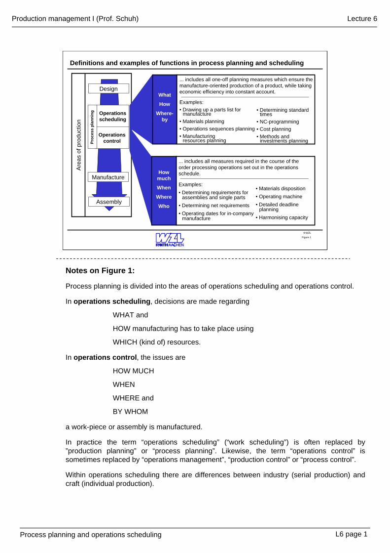
Notes on Figure 1:
Process planning is divided into the areas of operations scheduling and operations control.
In operations scheduling, decisions are made regarding
WHAT and
HOW manufacturing has to take place using
WHICH (kind of) resources.
In operations control, the issues are
HOW MUCH
WHEN
WHERE and
BY WHOM
a work-piece or assembly is manufactured.
In practice the term “operations scheduling” (“work scheduling”) is often replaced by ”production planning” or “process planning”. Likewise, the term “operations control” is sometimes replaced by “operations management”, “production control” or “process control”.
Within operations scheduling there are differences between industry (serial production) and craft (individual production).
L6 page 1
Process planning and operations scheduling
Production management I (Prof. Schuh) Lecture 6
WZL©
Input and output documents of process planning
Figure 2
Planning documents/ toolsInput documents
Design drawing
Welle
Design parts list
Order data
machine filestandard work schedulescomputing
Work schedule
NC-program
Output documents
Order specific follow-up documents to work schedule
Non-order specific additional documents
Drawing of manufacturing resources
Quality control plan
Manufacturing parts list
Arbeitsplan
Adjustment of capacity
Completed with order
data
Work progress controlEfficiency surveyUse of material
(total/ partial deduction)
Compliance with deadlines
Operations scheduling
Operations controlProc
ess
plan
ning
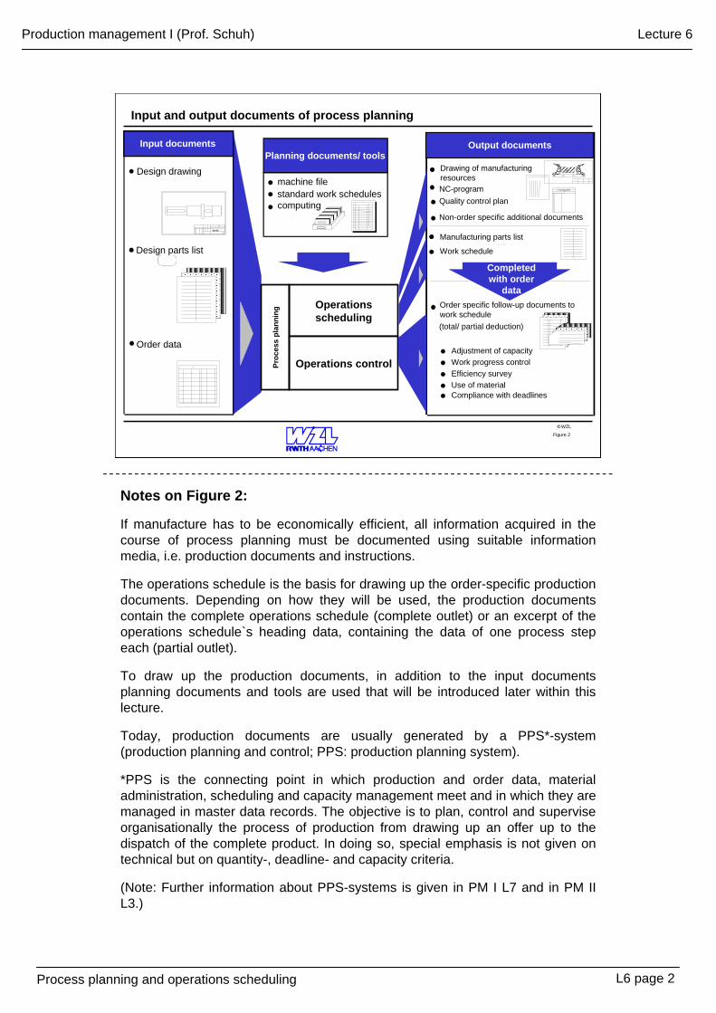
Notes on Figure 2:
If manufacture has to be economically efficient, all information acquired in the course of process planning must be documented using suitable information media, i.e. production documents and instructions.
The operations schedule is the basis for drawing up the order-specific production documents. Depending on how they will be used, the production documents contain the complete operations schedule (complete outlet) or an excerpt of the operations schedule`s heading data, containing the data of one process step each (partial outlet).
To draw up the production documents, in addition to the input documents planning documents and tools are used that will be introduced later within this lecture.
Today, production documents are usually generated by a PPS*-system (production planning and control; PPS: production planning system).
*PPS is the connecting point in which production and order data, material administration, scheduling and capacity management meet and in which they are managed in master data records. The objective is to plan, control and supervise organisationally the process of production from drawing up an offer up to the dispatch of the complete product. In doing so, special emphasis is not given on technical but on quantity-, deadline- and capacity criteria.
(Note: Further information about PPS-systems is given in PM I L7 and in PM II L3.)
L6 page 2
Process planning and operations scheduling
Production management I (Prof. Schuh) Lecture 6
WZL©
Operations schedule for the manufacture of a drive shaft
Figure 3
Saw round stock to 345 mm length10
20
30
40
50
60
70
300
340
360
350
400
510
900
4101
4201
4313
4407
4751
4908
9002
04
06
08
07
09
07
-
30
30
30
20
45
20
10
10,0
2,0
2,6
5,2
4,7
6,7
3,8
07/19/2002W. Müller
Drive shaft
Sheet: Date:Engineer:
Work ScheduleOrder No.
Drawing No..:Quantity:
Material: Un-machined shape and dimensions: Un-machined weight: 7.6 kg
Finished weight: 4.6 kg
Work cycle No. Work cycle description Cost center Wage
groupMachine
group
Manufacturing auxiliary
resources
Round stock 60 mmSt 50
1-20
1
-10011051
1101/1121/1131
1201/1231/12333104
-
-
170-0542Designation:Area:
t[min]
r t[min]
e
Cut round stock to 340 mm and centre
Mill feather key groove
Drill threaded holes and cut threads
Turn shaft completely
Finished part control
Grind bearing seats
PM1V6B3Header Organisa-tional data
Task specific
data
Work cycle
specific data
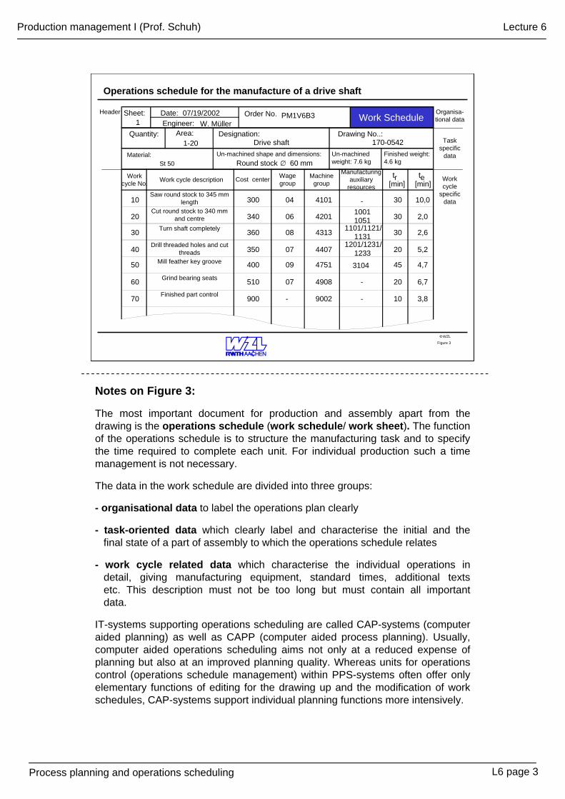
Notes on Figure 3:
The most important document for production and assembly apart from the drawing is the operations schedule (work schedule/ work sheet). The function of the operations schedule is to structure the manufacturing task and to specify the time required to complete each unit. For individual production such a time management is not necessary.
The data in the work schedule are divided into three groups:
- organisational data to label the operations plan clearly
- task-oriented data which clearly label and characterise the initial and the final state of a part of assembly to which the operations schedule relates
- work cycle related data which characterise the individual operations in detail, giving manufacturing equipment, standard times, additional texts etc. This description must not be too long but must contain all importantdata.
IT-systems supporting operations scheduling are called CAP-systems (computer aided planning) as well as CAPP (computer aided process planning). Usually, computer aided operations scheduling aims not only at a reduced expense of planning but also at an improved planning quality. Whereas units for operations control (operations schedule management) within PPS-systems often offer only elementary functions of editing for the drawing up and the modification of work schedules, CAP-systems support individual planning functions more intensively.
L6 page 3
Process planning and operations scheduling
Production management I (Prof. Schuh) Lecture 6
WZL©
Functions of operations scheduling
Functions of operations scheduling
short term planning functions
long-term planning functionsshort-/ long-term planning functions
Process parts lists Draw up work schedules
NC-programming Planning manu-facturing resources
Cost planning Quality assurance Investment planning
Methods planning
Planning preparation Material planning
Draw up
• assembly part lists• production part lists
• production work schedule
• assembly work schedule
• Write parts programs -NC-machines -robots
• Developing production resources for special purpose machining tasks
• Preliminary costing• Feasibility study
• Inspection planning• Quality planning
Planning
• manufacturing resources
• facilities
Developing
• production methods• planning methods
• Consult design dept.
• Compile planning documents
•Planning: types of store and store locations
•Logistic concepts
Figure 4
Notes on Figure 4:
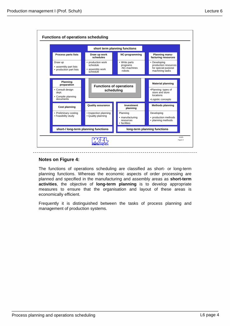
The functions of operations scheduling are classified as short- or long-term planning functions. Whereas the economic aspects of order processing are planned and specified in the manufacturing and assembly areas as short-term activities, the objective of long-term planning is to develop appropriate measures to ensure that the organisation and layout of these areas is economically efficient.
Frequently it is distinguished between the tasks of process planning and management of production systems.
L6 page 4
Process planning and operations scheduling
Production management I (Prof. Schuh) Lecture 6
WZL©
Planning methods for drawing up operations schedules
Figure 5
Search criteria:- Drawing No.- Part designation- Classification No.
Planningexperience
Variants planningBasis: standard work schedule
Application useful only in the case of a limited number of part categories
Adjustments planningBasis: similar or old work schedule availableApplication to part familiesSelective access to work schedule required
Basis: expert knowledge and availabilityof planning documents
Not part-based
Planning from scratch (new)
Repeat planningBasis: same or old work schedule available
Modification of operational data
Work schedulePart No.
4711
Stock of work schedules
Planningdocuments
Standard-Work
schedule
Pla
nnin
g ef
fort
Application in case of changes in production conditions or in work-pieces
Notes on Figure 5:
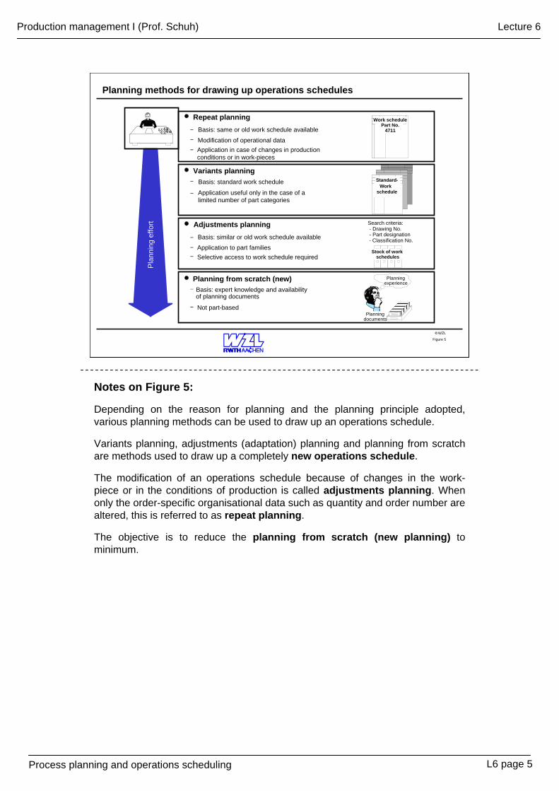
Depending on the reason for planning and the planning principle adopted, various planning methods can be used to draw up an operations schedule.
Variants planning, adjustments (adaptation) planning and planning from scratch are methods used to draw up a completely new operations schedule.
The modification of an operations schedule because of changes in the work-piece or in the conditions of production is called adjustments planning. When only the order-specific organisational data such as quantity and order number are altered, this is referred to as repeat planning.
The objective is to reduce the planning from scratch (new planning) to minimum.
L6 page 5
Process planning and operations scheduling
Production management I (Prof. Schuh) Lecture 6
WZL©
Process sequence to draw up operations schedules
Machining taskDesign drawingQuantity
Arbeitsplan
Specification of un-machined partType/ shapeDimensionsWeight
Arbeitsplan
Determination of work cycle sequenceWork cyclesSub-work cycles
Arbeitsplan
Selection of production resourcesMachinesJigs and fixturesTools
Arbeitsplan
Determining standard timesSet-up timesUnit times
Figure 6
Notes on Figure 6:
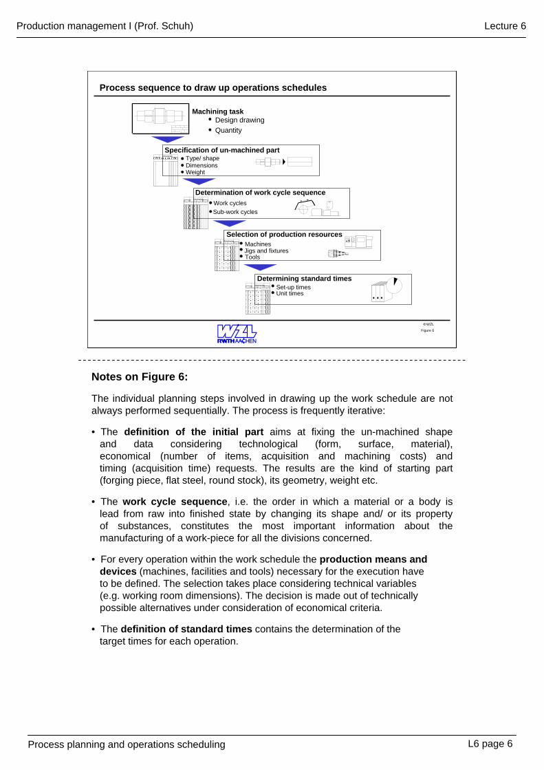
The individual planning steps involved in drawing up the work schedule are not always performed sequentially. The process is frequently iterative:
• The definition of the initial part aims at fixing the un-machined shape and data considering technological (form, surface, material),economical (number of items, acquisition and machining costs) and timing (acquisition time) requests. The results are the kind of starting part (forging piece, flat steel, round stock), its geometry, weight etc.
• The work cycle sequence, i.e. the order in which a material or a body is lead from raw into finished state by changing its shape and/ or its property of substances, constitutes the most important information about the manufacturing of a work-piece for all the divisions concerned.
• For every operation within the work schedule the production means anddevices (machines, facilities and tools) necessary for the execution have to be defined. The selection takes place considering technical variables (e.g. working room dimensions). The decision is made out of technically possible alternatives under consideration of economical criteria.
• The definition of standard times contains the determination of the target times for each operation.
L6 page 6
Process planning and operations scheduling
Production management I (Prof. Schuh) Lecture 6
WZL©
Structure and calculation of standard times
Time per unit te
Setting-up time tr
Conceptual meaning of standard times Structure of standard times Approach to calculating
standard times
Preparing operating resources e.g. procure tools, set up, take down
Basic setting-up time trg
Setting-up additional time trv
Setting-up recovery time trer
+
+
=
+
Non-productive time tn
Additional time tv
Recovery time ter
+
+
=
Productive time th+
Basic time tg
Execution time ta = te * m
Order time T = tr + ta = tr + (te * m)
Time with direct progress in relation to production order
Time for people to recover
Irregularly occurring times, e.g. machine starting times
Regular times, contributing only indirectly to work
Irregularly occurring times, e.g. preparation at beginning of shift
Time for people to recover
Machine specific tables
Supplement (approx. 5-15%) of setting-up time (allowance)
Supplement, depending on level and duration of load
Calculate (guideline values for machining data), measuring, comparing
Machine-specific tables
Supplement (approx. 5-15%) of basic time (allowance)
Supplement, depending on level and duration of load
m = quantity
Figure 7
Notes on Figure 7:
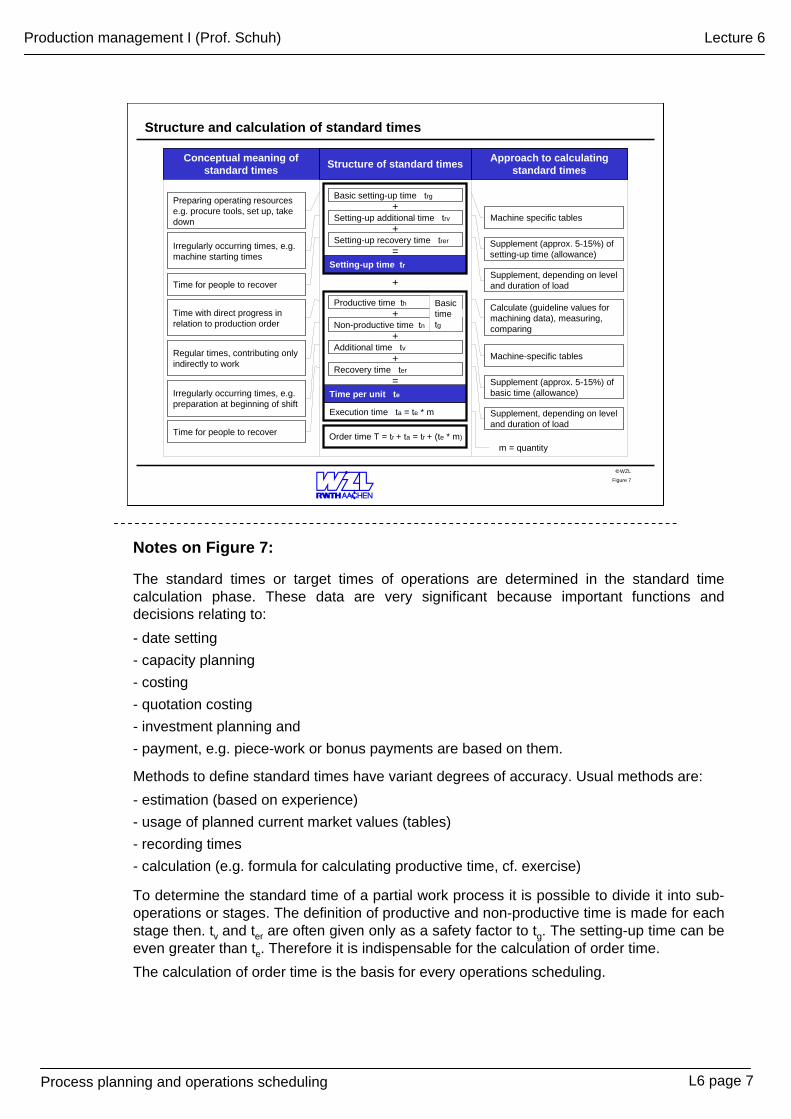
The standard times or target times of operations are determined in the standard time calculation phase. These data are very significant because important functions and decisions relating to:- date setting- capacity planning- costing- quotation costing- investment planning and- payment, e.g. piece-work or bonus payments are based on them.
Methods to define standard times have variant degrees of accuracy. Usual methods are:- estimation (based on experience)- usage of planned current market values (tables)- recording times- calculation (e.g. formula for calculating productive time, cf. exercise)
To determine the standard time of a partial work process it is possible to divide it into sub-operations or stages. The definition of productive and non-productive time is made for each stage then. tv and ter are often given only as a safety factor to tg. The setting-up time can be even greater than te. Therefore it is indispensable for the calculation of order time.The calculation of order time is the basis for every operations scheduling.
L6 page 7
Process planning and operations scheduling
Production management I (Prof. Schuh) Lecture 6
WZL©Figure 8
Tool group
Date of process
Work cycle description
Work cycle number
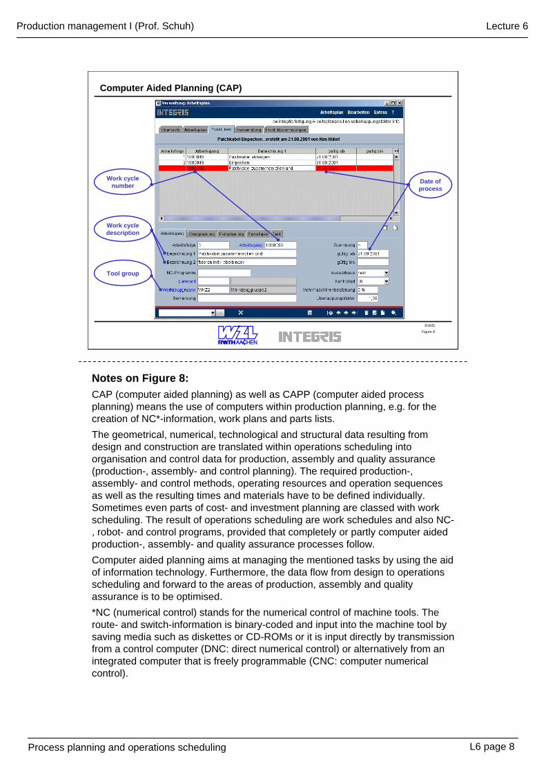
Computer Aided Planning (CAP)
Notes on Figure 8:CAP (computer aided planning) as well as CAPP (computer aided process planning) means the use of computers within production planning, e.g. for the creation of NC*-information, work plans and parts lists. The geometrical, numerical, technological and structural data resulting from design and construction are translated within operations scheduling into organisation and control data for production, assembly and quality assurance (production-, assembly- and control planning). The required production-, assembly- and control methods, operating resources and operation sequences as well as the resulting times and materials have to be defined individually. Sometimes even parts of cost- and investment planning are classed with work scheduling. The result of operations scheduling are work schedules and also NC-, robot- and control programs, provided that completely or partly computer aided production-, assembly- and quality assurance processes follow. Computer aided planning aims at managing the mentioned tasks by using the aid of information technology. Furthermore, the data flow from design to operations scheduling and forward to the areas of production, assembly and quality assurance is to be optimised. *NC (numerical control) stands for the numerical control of machine tools. The route- and switch-information is binary-coded and input into the machine tool by saving media such as diskettes or CD-ROMs or it is input directly by transmission from a control computer (DNC: direct numerical control) or alternatively from an integrated computer that is freely programmable (CNC: computer numerical control).
L6 page 8
Process planning and operations scheduling
Production management I (Prof. Schuh) Lecture 6
WZL©Figure 9
Basic components of CAP-systems
Definition of work cycle progression
Selection of machines
Definition of sub-work cycle progression
Selection of tools and mechanisms
definition of work cycle data
System progress control
Data input
Data output
neutral to business dependent on business
Current planning
data
Planning master
data
Standard processing
Use of data
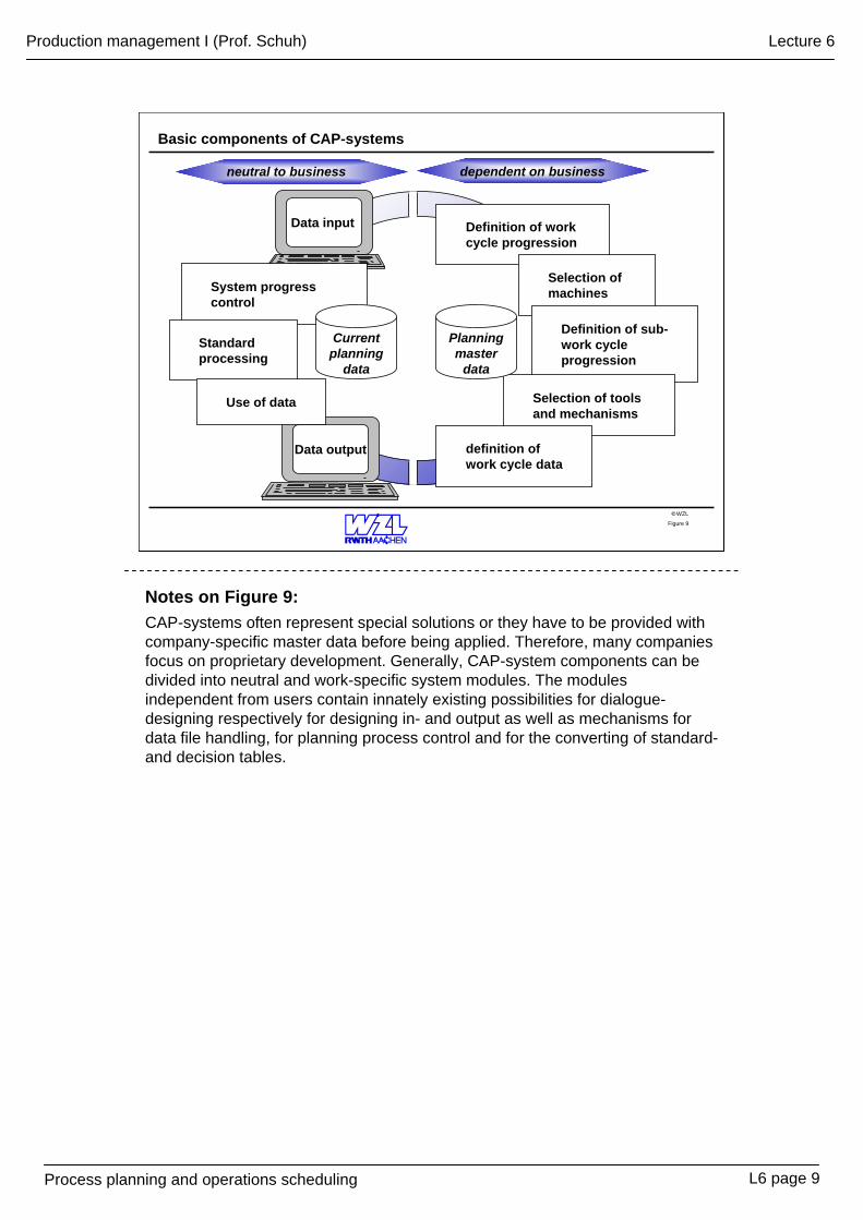
Notes on Figure 9:CAP-systems often represent special solutions or they have to be provided with company-specific master data before being applied. Therefore, many companies focus on proprietary development. Generally, CAP-system components can be divided into neutral and work-specific system modules. The modules independent from users contain innately existing possibilities for dialogue-designing respectively for designing in- and output as well as mechanisms for data file handling, for planning process control and for the converting of standard-and decision tables.
L6 page 9
Process planning and operations scheduling
Production management I (Prof. Schuh) Lecture 6
WZL©
Planning stages in the NC-process chain
Work schedule
Work cycle data
Work cycle
20 47115
Work cycle No. Cost centre
NC-turning
Process planning (overall planning)Planning of the production process
Operations planning (Detailed planning)Detailing of work cycles
10 FacingTool
Work cycle:
SCLR 2525SWC-No.
NC-programming
PROGRAM%N001 G91 S200 M04N002 T0103 M06
Operation planNC-turning
Sub-work-cycle
Figure 10
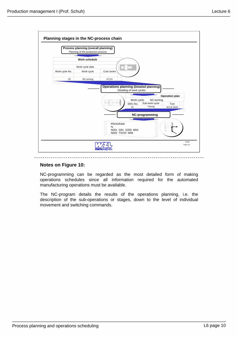
Notes on Figure 10:
NC-programming can be regarded as the most detailed form of making operations schedules since all information required for the automated manufacturing operations must be available.
The NC-program details the results of the operations planning, i.e. thedescription of the sub-operations or stages, down to the level of individual movement and switching commands.
L6 page 10
Process planning and operations scheduling
Production management I (Prof. Schuh) Lecture 6
WZL©
Methogical and organisational classification of NC-programming systems
N010 G17N020 G41 D2N030 G01 X125 Y050 F300N040 X105 Y040N050 X090N060 G03 X075 Y025 J15N070 G01 X075 Y020N080 X025 Y060N090 X045 Y060
Org
anis
atio
nal
cate
gory
Met
hodi
cal
cate
gory
Prog
ram
min
g m
etho
ds
Remote from machine Remote from machine
mechanical
manual
Machine-oriented, linked to machine
Menu
Text editor
Graphical-inter-active program-ming systems
Computer programming systems
Shop-floor-based programming systems
Shop-floor programming systems (manual input)
Record-based programming conforming to DIN
Figure 11
Notes on Figure 11:
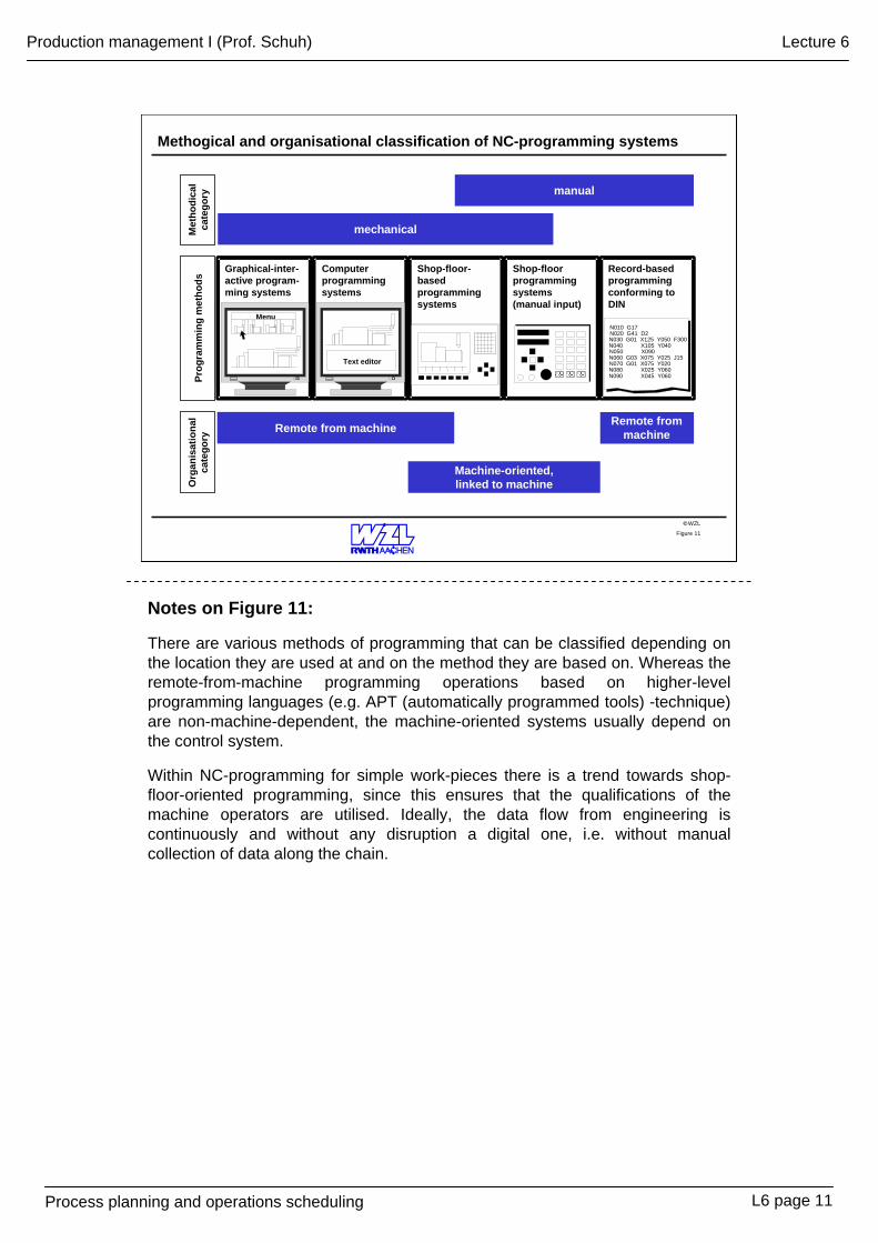
There are various methods of programming that can be classified depending on the location they are used at and on the method they are based on. Whereas the remote-from-machine programming operations based on higher-level programming languages (e.g. APT (automatically programmed tools) -technique) are non-machine-dependent, the machine-oriented systems usually depend on the control system.
Within NC-programming for simple work-pieces there is a trend towards shop-floor-oriented programming, since this ensures that the qualifications of the machine operators are utilised. Ideally, the data flow from engineering is continuously and without any disruption a digital one, i.e. without manual collection of data along the chain.
L6 page 11
Process planning and operations scheduling
Production management I (Prof. Schuh) Lecture 6
WZL©
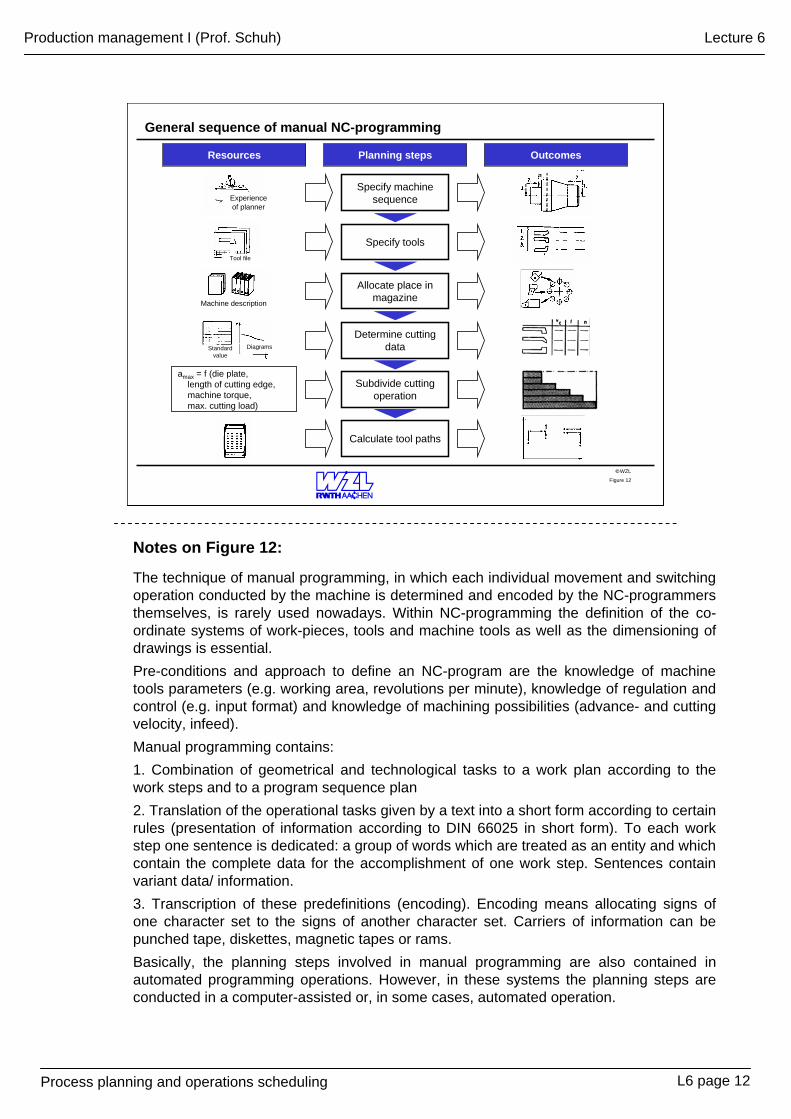
General sequence of manual NC-programming
Figure 12
OutcomesPlanning stepsResources
Specify machine sequence
Specify tools
Allocate place in magazine
Determine cutting data
Subdivide cutting operation
Calculate tool paths
amax = f (die plate, length of cutting edge, machine torque, max. cutting load)
Experience of planner
Tool file
Machine description
DiagramsStandard value
Notes on Figure 12:
The technique of manual programming, in which each individual movement and switching operation conducted by the machine is determined and encoded by the NC-programmers themselves, is rarely used nowadays. Within NC-programming the definition of the co-ordinate systems of work-pieces, tools and machine tools as well as the dimensioning of drawings is essential. Pre-conditions and approach to define an NC-program are the knowledge of machine tools parameters (e.g. working area, revolutions per minute), knowledge of regulation and control (e.g. input format) and knowledge of machining possibilities (advance- and cutting velocity, infeed). Manual programming contains:1. Combination of geometrical and technological tasks to a work plan according to the work steps and to a program sequence plan2. Translation of the operational tasks given by a text into a short form according to certain rules (presentation of information according to DIN 66025 in short form). To each work step one sentence is dedicated: a group of words which are treated as an entity and which contain the complete data for the accomplishment of one work step. Sentences contain variant data/ information. 3. Transcription of these predefinitions (encoding). Encoding means allocating signs of one character set to the signs of another character set. Carriers of information can be punched tape, diskettes, magnetic tapes or rams.Basically, the planning steps involved in manual programming are also contained in automated programming operations. However, in these systems the planning steps are conducted in a computer-assisted or, in some cases, automated operation.
L6 page 12
Process planning and operations scheduling
Production management I (Prof. Schuh) Lecture 6
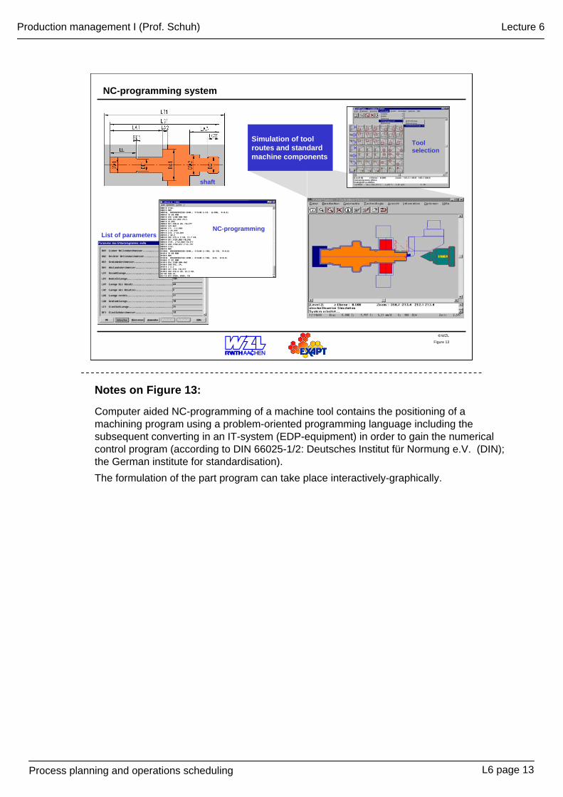
WZL©Figure 13
List of parametersNC-programming
shaft
Simulation of tool routes and standard machine components
Tool selection
NC-programming system
L6 page 13
Notes on Figure 13:
Computer aided NC-programming of a machine tool contains the positioning of a machining program using a problem-oriented programming language including the subsequent converting in an IT-system (EDP-equipment) in order to gain the numerical control program (according to DIN 66025-1/2: Deutsches Institut für Normung e.V. (DIN); the German institute for standardisation).The formulation of the part program can take place interactively-graphically.
Process planning and operations scheduling
Production management I (Prof. Schuh) Lecture 6
WZL©
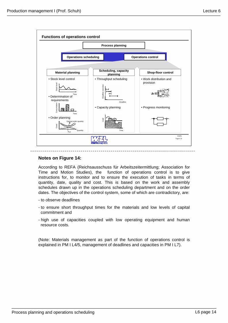
Functions of operations control
Figure 14
Process planning
Operations scheduling Operations control
• Stock level control
• Determination of requirements
• Capacity planning
• Throughput scheduling
• Progress monitoring
• Work distribution and provision
• Order planning
Material planning Scheduling, capacity planning Shop-floor control
Sto
ck le
vel
Time
Time
Time
Deadline
Quantity
Optimal order quantity
Xopt
Cos
tsC
onsu
mpt
ion
Dea
dlin
e ov
ervi
ewLo
ad
Notes on Figure 14:
According to REFA (Reichsausschuss für Arbeitszeitermittlung; Association for Time and Motion Studies), the function of operations control is to give instructions for, to monitor and to ensure the execution of tasks in terms of quantity, date, quality and cost. This is based on the work and assembly schedules drawn up in the operations scheduling department and on the order dates. The objectives of the control system, some of which are contradictory, are:
- to observe deadlines
- to ensure short throughput times for the materials and low levels of capital commitment and
- high use of capacities coupled with low operating equipment and human resource costs.
(Note: Materials management as part of the function of operations control is explained in PM I L4/5, management of deadlines and capacities in PM I L7).
L6 page 14
Process planning and operations scheduling
Production management I (Prof. Schuh) Lecture 6
WZL©
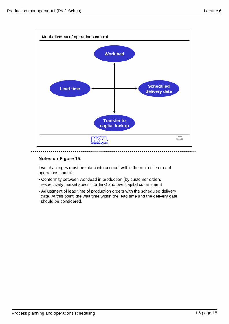
Multi-dilemma of operations control
Figure 15
Lead time Scheduleddelivery date
Workload
Transfer tocapital lockup
Notes on Figure 15:
Two challenges must be taken into account within the multi-dilemma of operations control:• Conformity between workload in production (by customer orders respectively market specific orders) and own capital commitment
• Adjustment of lead time of production orders with the scheduled delivery date. At this point, the wait time within the lead time and the delivery date should be considered.
L6 page 15
Process planning and operations scheduling
Production management I (Prof. Schuh) Lecture 6
WZL©
Order- and capacity-based scheduling
A
B
C
Deadline overview Deadline overview
Phase 1(Focus: work-piece)
Phase 2(Focus: machine)
Order-based scheduling Capacity-based scheduling
Deadline plan
Order 1 1.1, 1.2, 1.3
Deadline plan
Order 1 1.1, 1.2, 1.3 Order 2 2.2, 2.3Order 3 3.1, 3.2, 3.3
1.1
1.2
1.3
Lead time for order 1
Wor
k sy
stem
s
Deadline
A
B
C
1.1
1.2
1.3
Lead time for order 1
Deadline
3.1
2.2 3.2
2.3 3.3
Figure 16
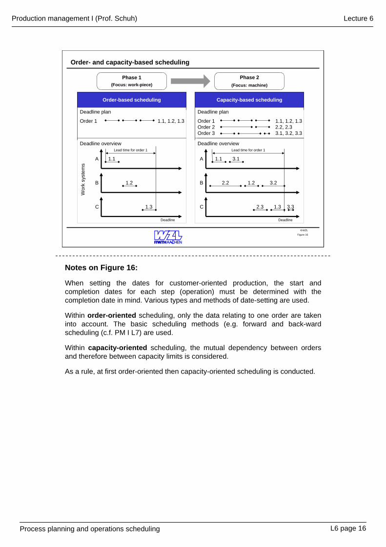
Notes on Figure 16:
When setting the dates for customer-oriented production, the start and completion dates for each step (operation) must be determined with the completion date in mind. Various types and methods of date-setting are used.
Within order-oriented scheduling, only the data relating to one order are taken into account. The basic scheduling methods (e.g. forward and back-ward scheduling (c.f. PM I L7) are used.
Within capacity-oriented scheduling, the mutual dependency between orders and therefore between capacity limits is considered.
As a rule, at first order-oriented then capacity-oriented scheduling is conducted.
L6 page 16
Process planning and operations scheduling
Production management I (Prof. Schuh) Lecture 6
WZL©Figure 17
Alternativ
e-
machine optio
ns
Alternativ
e-
machine optio
ns
Load
Time
Technicalcapacity harmonisation
Time
Time-based capacity harmonisation
Time
Load
Alternativ
e
machine optio
ns
Machine AMachine B
Machine C
Machine AMachine B
Combination of technical and time-based capacity harmonisation
Time- and machine-based harmonisation of capacity
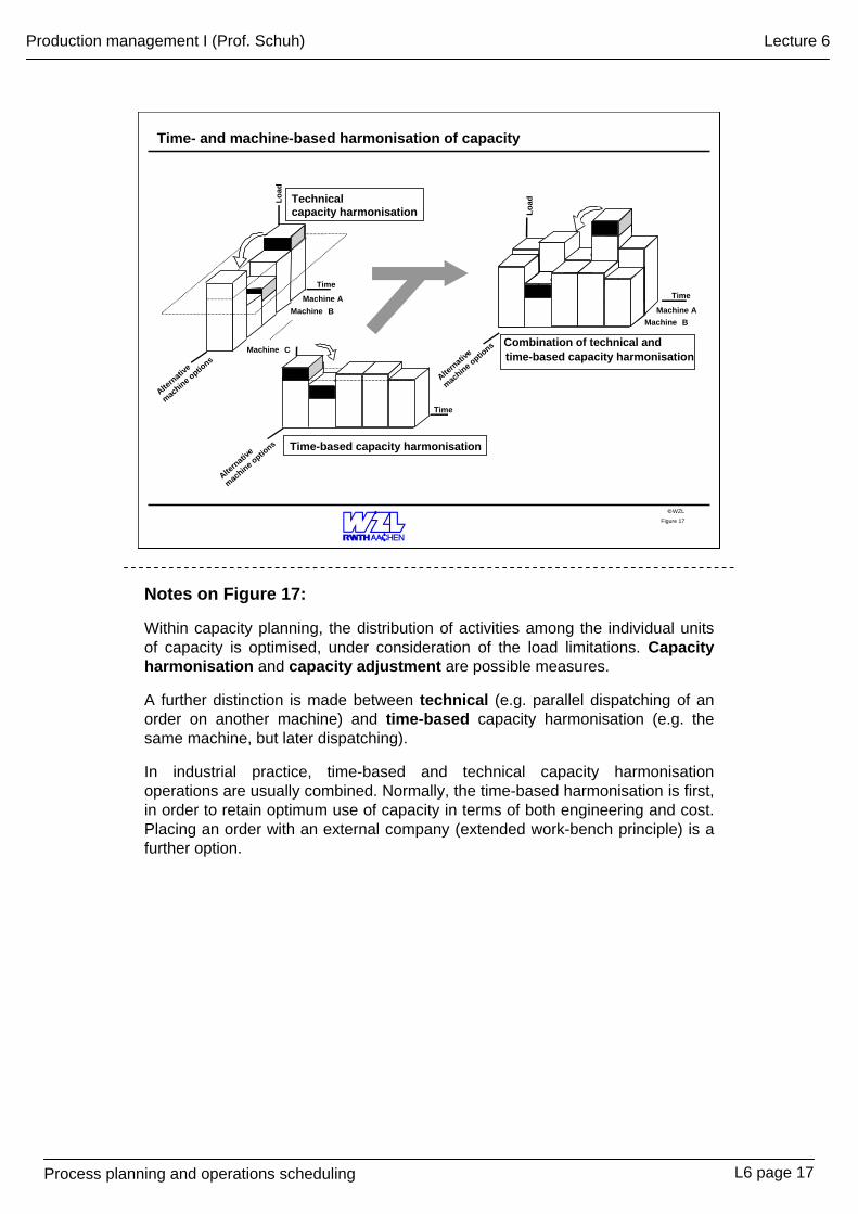
Notes on Figure 17:
Within capacity planning, the distribution of activities among the individual units of capacity is optimised, under consideration of the load limitations. Capacity harmonisation and capacity adjustment are possible measures.
A further distinction is made between technical (e.g. parallel dispatching of an order on another machine) and time-based capacity harmonisation (e.g. the same machine, but later dispatching).
In industrial practice, time-based and technical capacity harmonisation operations are usually combined. Normally, the time-based harmonisation is first, in order to retain optimum use of capacity in terms of both engineering and cost. Placing an order with an external company (extended work-bench principle) is a further option.
L6 page 17
Process planning and operations scheduling
Production management I (Prof. Schuh) Lecture 6
WZL©Figure 18
occupied
free
Handling time
1. Cut within production
2. Cut within production
Transitional period Control periodStart-up of production A
1. Cut within production
2. Cut within production
Control period
Transitional period
Handling timeStart-up of production B
1. Day 2. Day 3. Day
1. Produktions-schnitt fürAuftrag B
2. Produktion-schnitt fürAuftrag B
Belegungdurch
Auftrag A
Belegungdurch
Auftrag C(Spittfaktor0)
FreiFrei1. Produktions-
schnitt fürAuftrag B
2. Produktion-schnitt fürAuftrag B
Belegungdurch
Auftrag A
Belegungdurch
Auftrag C(Spittfaktor0)
FreiFrei1. cut within
production for order B
2. cut within production for order B
Occupied with
order A
Occupied with order C
(Split factor 0)
FreeFree
Cap
acity
of m
achi
ne 1
Capacity management (PPS-system)
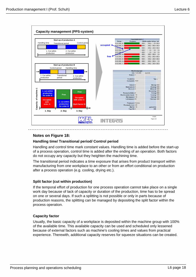
Notes on Figure 18:Handling time/ Transitional period/ Control periodHandling and control time mark constant values. Handling time is added before the start-up of a process operation, control time is added after the ending of an operation. Both factors do not occupy any capacity but they heighten the machining time.The transitional period indicates a time exposure that arises from product transport within manufacturing from one workplace to an other or from an effort conditional on production after a process operation (e.g. cooling, drying etc.).
Split factor (cut within production)If the temporal effort of production for one process operation cannot take place on a single work day because of lack of capacity or duration of the production, time has to be spread on one or several days. If such a splitting is not possible or only in parts because of production reasons, the splitting can be managed by depositing the split factor within the process operation.
Capacity factorUsually, the basic capacity of a workplace is deposited within the machine group with 100% of the available time. This available capacity can be used and scheduled only lessened because of external factors such as machine's cooling times and values from practical experience. Therewith, additional capacity reserves for squeeze situations can be created.
L6 page 18
Process planning and operations scheduling
Production management I (Prof. Schuh) Lecture 6
WZL©Figure 19
Measures for adapting to capacity
Internal/ external alternative capacity
Overtime/ short-time working Additional shift Investment
Internal influencing factors
External influencing factors
• effectiveness• duration• internal priority
• external priority• penalty • labour market• economic situation
Selection and execution of measures geared to adapting to capacity
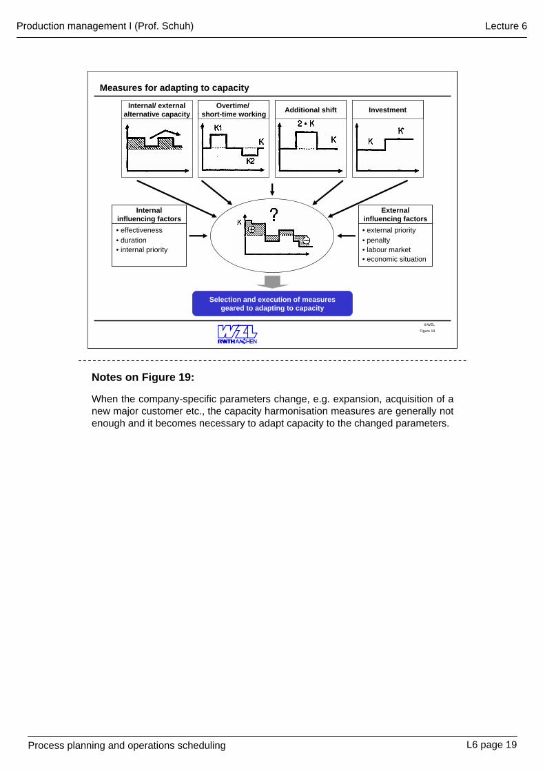
Notes on Figure 19:
When the company-specific parameters change, e.g. expansion, acquisition of a new major customer etc., the capacity harmonisation measures are generally not enough and it becomes necessary to adapt capacity to the changed parameters.
L6 page 19
Process planning and operations scheduling
Production management I (Prof. Schuh) Lecture 6
WZL©Figure 20
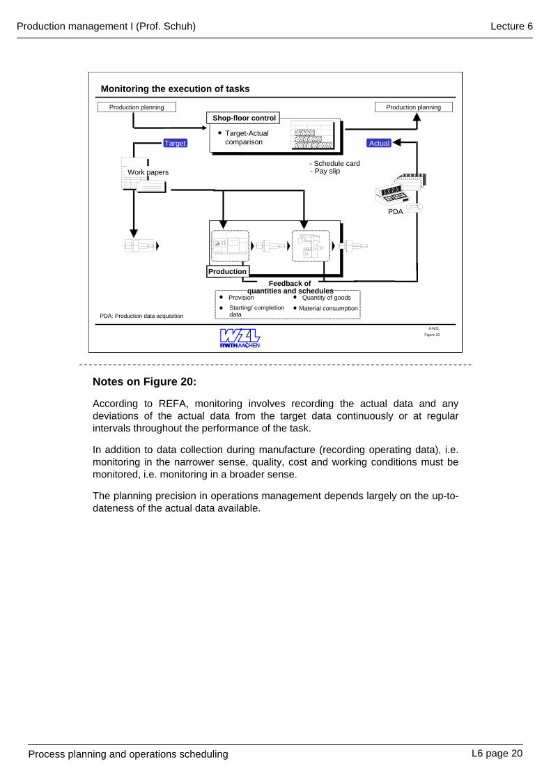
Monitoring the execution of tasks
Production
Material consumption
Quantity of goodsStarting/ completion data
Provision
Target-Actual comparison
Shop-floor control
Work papers
Feedback ofquantities and schedules
Target Actual
PDA
- Schedule card- Pay slip
Production planning Production planning
PDA: Production data acquisition
Notes on Figure 20:
According to REFA, monitoring involves recording the actual data and any deviations of the actual data from the target data continuously or at regular intervals throughout the performance of the task.
In addition to data collection during manufacture (recording operating data), i.e. monitoring in the narrower sense, quality, cost and working conditions must be monitored, i.e. monitoring in a broader sense.
The planning precision in operations management depends largely on the up-to-dateness of the actual data available.
L6 page 20
Process planning and operations scheduling
Production management I (Prof. Schuh) Lecture 6
WZL©Figure 21
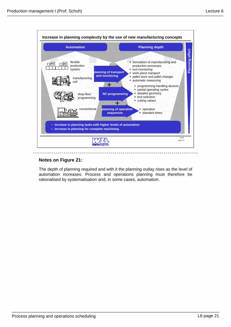
Increase in planning complexity by the use of new manufacturing concepts
Automation Planning depth
planning of transport and monitoring
NC-programming
planning of operationsequences
• increase in planning tasks with higher levels of automation• increase in planning for complete machining
+
+
Simulation of manufacturing andproduction processestool monitoringwork-piece transportpallet store and pallet changerautomatic measuring
operationstandard times
programming handling devicespartial operating cycles detailed geometrytool selectioncutting values
Plan
ning
effo
rt
conventional
shop-floorprogramming
manufacturingcell
flexible productionsystem
Notes on Figure 21:
The depth of planning required and with it the planning outlay rises as the level of automation increases. Process and operations planning must therefore be rationalised by systematisation and, in some cases, automation.
L6 page 21
Process planning and operations scheduling
Production management I (Prof. Schuh) Lecture 6
WZL©Figure 22
Systematisation
materials disposition
materials planning
working sheet –part list admin.
drawing up of work schedules
NC-programming
capacity planning
order scheduling
• sector• range of products• manufacturing structure• type of manufacture• manufacturing technology• organisational structure• staff training
Company parameters
• little outlay for processing and administration
• high quality planning and continuity• transparent planning procedures • short throughput times • gradual introduction and expansion
Requirements
Fields ofactivity ofprocess
planning
monitor progress
OrganisationProduct-oriented structureOrder processing centre
DocumentsCatalogues of materialsCatalogues of standard times
Planning methods/ toolsPlanning on the basis of - planning results- planning rules
Target forrationalisation
IT-Systems
AutomationOptions for rationalisation
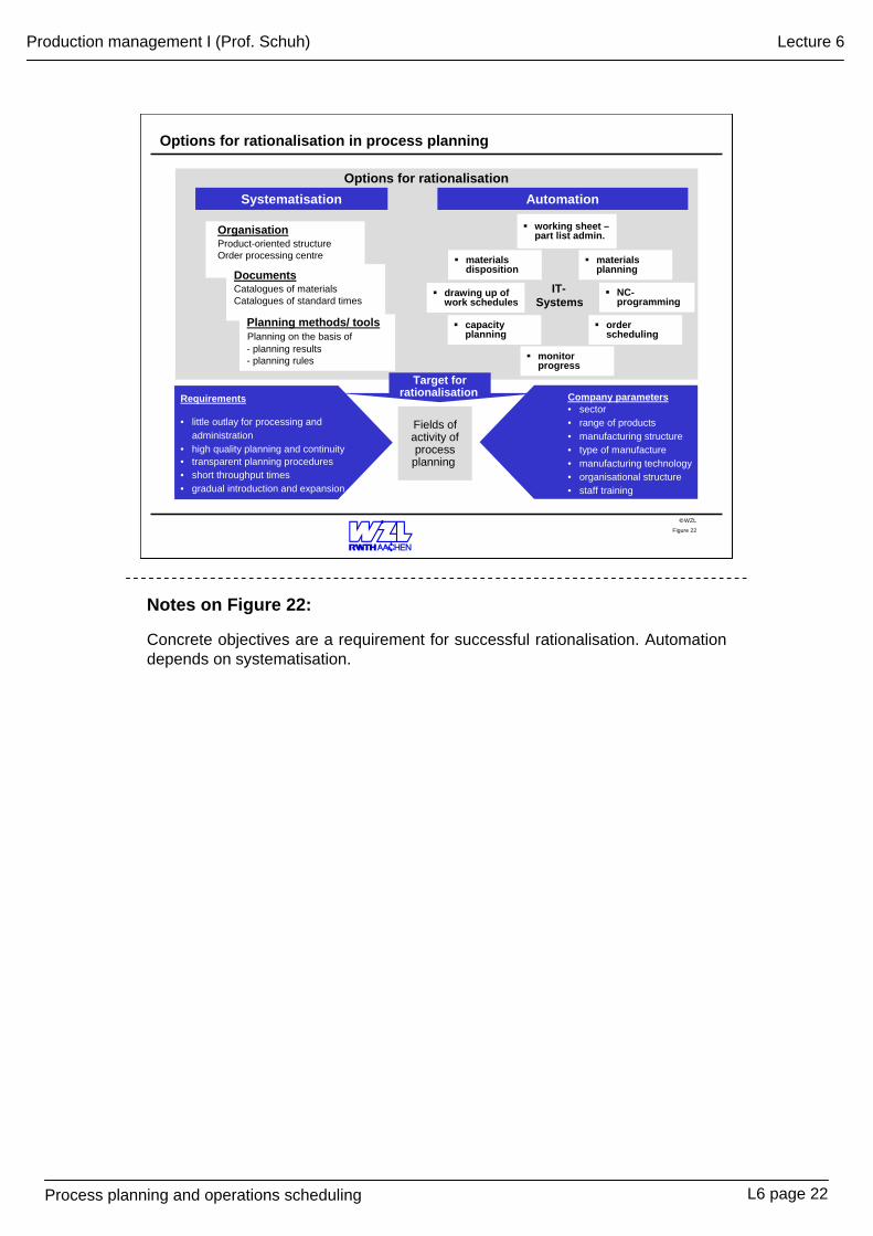
Options for rationalisation in process planning
Notes on Figure 22:
Concrete objectives are a requirement for successful rationalisation. Automation depends on systematisation.
L6 page 22
Process planning and operations scheduling
Production management I (Prof. Schuh) Lecture 6
WZL©Figure 23
adjust
similar or old workschedules
4711
Mill grooveD > xxL < yy
D < xyL > yx
D > xxL < yy
D < xyL > yx
shaft 4711D > xxL < yy
D < xyL > yx
fill in
standard workschedules
D > xxL < yy
D < xyL > yx
shaft
Repeat planning
Variantsplanning
Adjustmentsplanning
Planning fromscratch (new)
4712
4711
47104709
copy
same or old workschedules
KR- 47 11
draw up
catalogues,tables,..
+
Planningeffort
Bas
isA
ltern
ativ
e pl
anni
ng
met
hods
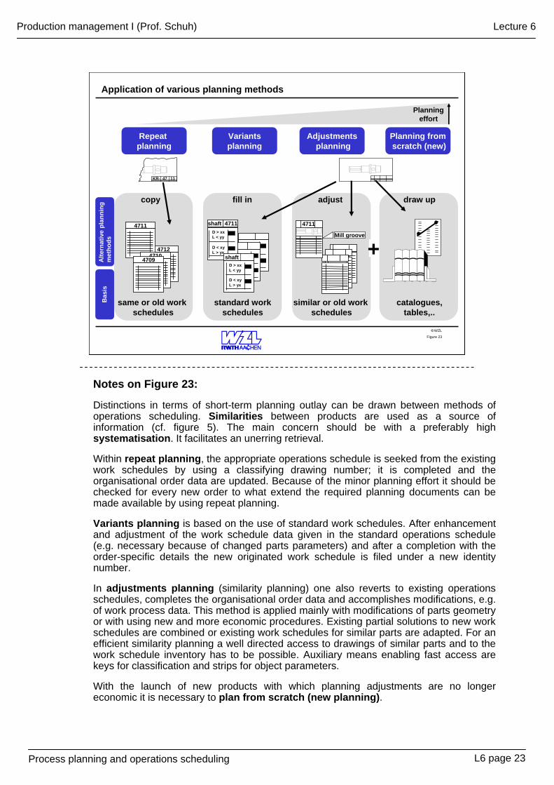
Application of various planning methods
Notes on Figure 23:
Distinctions in terms of short-term planning outlay can be drawn between methods of operations scheduling. Similarities between products are used as a source of information (cf. figure 5). The main concern should be with a preferably high systematisation. It facilitates an unerring retrieval.
Within repeat planning, the appropriate operations schedule is seeked from the existing work schedules by using a classifying drawing number; it is completed and the organisational order data are updated. Because of the minor planning effort it should be checked for every new order to what extend the required planning documents can be made available by using repeat planning.
Variants planning is based on the use of standard work schedules. After enhancement and adjustment of the work schedule data given in the standard operations schedule (e.g. necessary because of changed parts parameters) and after a completion with the order-specific details the new originated work schedule is filed under a new identity number.
In adjustments planning (similarity planning) one also reverts to existing operations schedules, completes the organisational order data and accomplishes modifications, e.g. of work process data. This method is applied mainly with modifications of parts geometry or with using new and more economic procedures. Existing partial solutions to new work schedules are combined or existing work schedules for similar parts are adapted. For an efficient similarity planning a well directed access to drawings of similar parts and to the work schedule inventory has to be possible. Auxiliary means enabling fast access are keys for classification and strips for object parameters.
With the launch of new products with which planning adjustments are no longer economic it is necessary to plan from scratch (new planning).
L6 page 23
Process planning and operations scheduling
Production management I (Prof. Schuh) Lecture 6
WZL©Figure 24
OPERATIONS SCHEDULING
• accuracy• up-to-dateness• reproducibility• ...
Requirements
• organisational data• feedstock data• operations• sub-operations• machine groups• cost centres• set-up times• times per unit
•cutting data•additional text
• ...
Data transfer
• level of automation• type of manufacture • proportion of skilledworkers
• lot size• ...
MANUFACTURE
• project structure• frequency scale(standard parts, similar parts,product group parts)
WORKPIECE ANALYSIS
ANALYSIS OF ACTION
incorporating• type of action• duration of action• planning methods• planning means
ANALYSIS OF INFORMATION
• document-boundcommunication
• non-document-boundcommunication
Mai
n fo
cuse
s of
ratio
nalis
atio
n
Methods for the rationalisation of operations scheduling
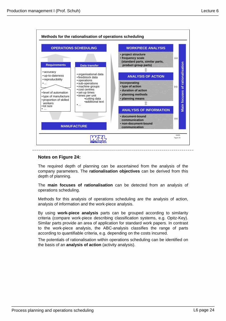
Notes on Figure 24:
The required depth of planning can be ascertained from the analysis of the company parameters. The rationalisation objectives can be derived from this depth of planning.
The main focuses of rationalisation can be detected from an analysis of operations scheduling.
Methods for this analysis of operations scheduling are the analysis of action, analysis of information and the work-piece analysis.
By using work-piece analysis parts can be grouped according to similarity criteria (compare work-piece describing classification systems, e.g. Opitz-Key). Similar parts provide an area of application for standard work papers. In contrast to the work-piece analysis, the ABC-analysis classifies the range of parts according to quantifiable criteria, e.g. depending on the costs incurred.The potentials of rationalisation within operations scheduling can be identified on the basis of an analysis of action (activity analysis).
L6 page 24
Process planning and operations scheduling
Production management I (Prof. Schuh) Lecture 6
WZL©Figure 25
Range of parts/ machining methods
frequency
Organisation Information flow
Planning methods
- planning from scratch- variants planning- similarity planning- repeat planning
HardwareSoftware
- operating system- applications software- communications software- firmware- ...
Planning aids
nomograms tablescatalogues
files
CAP/CAPP-System
Volume of project data
1997 2002
number
new working sheetsmodified working sheets
Factors impacting on the system used to draw up operations schedules
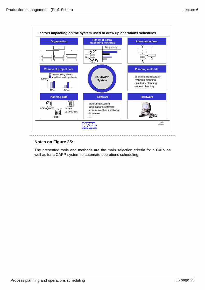
Notes on Figure 25:
The presented tools and methods are the main selection criteria for a CAP- as well as for a CAPP-system to automate operations scheduling.
L6 page 25
Produktionsmanagement I (Prof. Schuh)
Arbeitsvorbereitung / Arbeitsplanung
WZL©
Produktionsmanagement I- Anhang 6 -
Arbeitsvorbereitung / Arbeitsplanung
Vorlesungsbetreuer:M. Phornprapha, M. [email protected], R. 504Tel.: 0241-80-27383
A6 Seite I
Vorlesung 6
Produktionsmanagement I (Prof. Schuh)
Arbeitsvorbereitung / Arbeitsplanung
WZL©
Ausgangsteilbestimmung
Auftragsdaten Werkstückdaten Werkstoffdaten
Halbzeug Schmiedeteil
Ausgangsteilbestimmung
Bes
timm
ung
der
Roh
form
Erm
ittlu
ng d
er
Roh
teild
aten
Auftragsstückzahl: < 3000 Auftragsstückzahl: > 3000
Durchmesser[mm] Länge[mm] Gewicht[Kg/100mm]
MaterialkatalogWerkstoff: ST 50 Material: Stange rund, blank
40506070
2000200020002000
0,971,532,213,00
Ausgangsmaterial: Stange rund
Stückzahl: 2
60
345
• Material: Stange rund, blank
• Durchmesser: Ø = 60 mm
• Länge: L = 340 + 5 L = 345 mm
• Gewicht: G = 2,21 * 345/100 G = 7,6 Kg
Bild 1
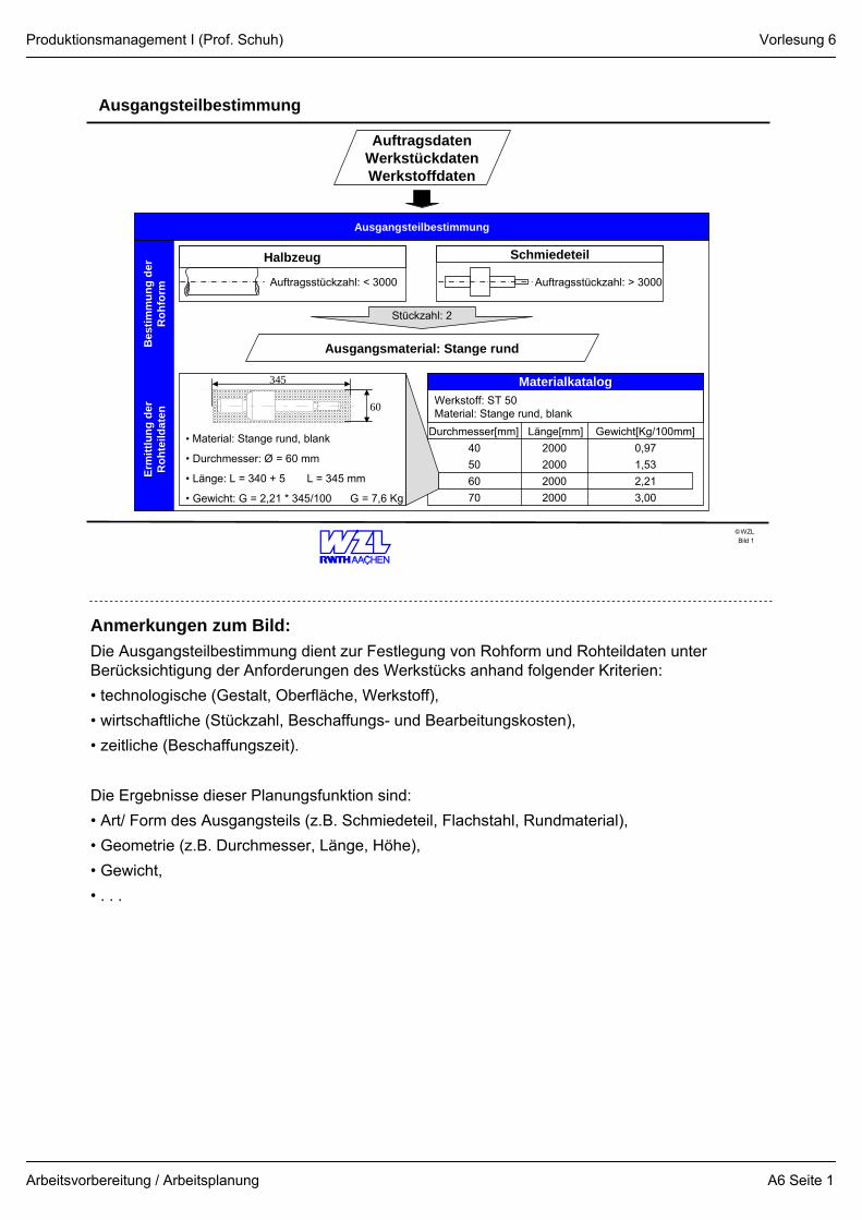
Anmerkungen zum Bild:Die Ausgangsteilbestimmung dient zur Festlegung von Rohform und Rohteildaten unter Berücksichtigung der Anforderungen des Werkstücks anhand folgender Kriterien:• technologische (Gestalt, Oberfläche, Werkstoff),• wirtschaftliche (Stückzahl, Beschaffungs- und Bearbeitungskosten),• zeitliche (Beschaffungszeit).
Die Ergebnisse dieser Planungsfunktion sind:• Art/ Form des Ausgangsteils (z.B. Schmiedeteil, Flachstahl, Rundmaterial),• Geometrie (z.B. Durchmesser, Länge, Höhe),• Gewicht,• . . .
Vorlesung 6
A6 Seite 1
Produktionsmanagement I (Prof. Schuh)
Arbeitsvorbereitung / Arbeitsplanung
WZL©
Arbeitsvorgangsfolgeermittlung
Arbeitsvorgangsfolgebestimmung
Fertigungsablauf ErläuterungAVO 10: Sägen
AVO 20: Ablängen und Zentrieren
AVO 30: Komplett Drehen
AVO 40: Bohren und Gewindeschneiden
AVO 50: Fräsen
AVO 60: Schleifen
Säge:Ausgangsmaterial: Stange rund, mit Aufmaß zum PlanenZentriermaschine:Vorbedingung für: -Drehen -Gewinde schneiden
-Bohren Drehmaschine:Vorbedingung für: -Fräsen -Schleifen
Bohrmaschine:2 Axialbohrungren M6 x 20 für die Befestigung eines DeckelsFräsmaschine: Nuten fräsen für Paßfeder mit Paarung P9
Schleifmaschine:Lagersitz auf Nennmaß schleifen
• Auftragsdaten• Rohteildaten
• verfügbare Fertigungsverfahren• Werkstückdaten
Bild 2
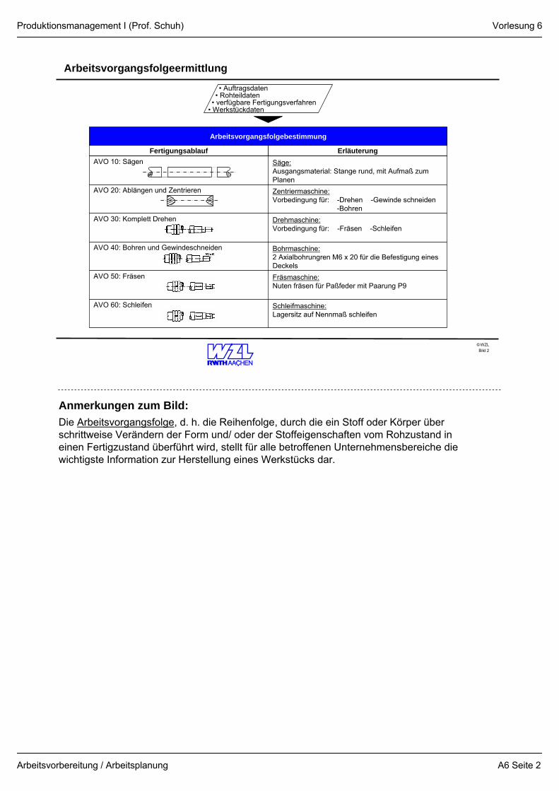
Anmerkungen zum Bild:Die Arbeitsvorgangsfolge, d. h. die Reihenfolge, durch die ein Stoff oder Körper über schrittweise Verändern der Form und/ oder der Stoffeigenschaften vom Rohzustand in einen Fertigzustand überführt wird, stellt für alle betroffenen Unternehmensbereiche die wichtigste Information zur Herstellung eines Werkstücks dar.
Vorlesung 6
A6 Seite 2
Produktionsmanagement I (Prof. Schuh)
Arbeitsvorbereitung / Arbeitsplanung
WZL©
Fertigungsmittelbestimmung
Daten desBeispiels
Fertigungsmittelbestimmung für Arbeitsvorgang "Komplett Drehen"
Mas
chin
enau
swah
lW
erkz
euga
usw
ahl
Spitzen-drehmaschine
NC-drehmaschine
Kopier-drehmaschine
Kostenstelle/ Lohngruppe
max. Durchmesser [mm]
max. Länge [mm]
Auftragsstückzahl
-
60
340
360/08
340
700
360/08
300
700
360/07
350
650
2
M1 M2 M3
Stückzahl50 100 150
M1
M2
M3
Prozess-kosten
21
M2 M3M1
WerkzeugkatalogBezeichnung
SchruppdrehmeißelLängs-HMSchruppdrehmeißelPlan-HM
Skizze Inv.-Nr.
1101
1102
Operation
Längs-schruppen
Werkzeug-Nr.
1101
• Auftragsdaten• Rohteildaten
• verfügbare Fertigungsverfahren• Werkstückdaten
Kostenstelle:360 Lohngruppe :08
Bild 3
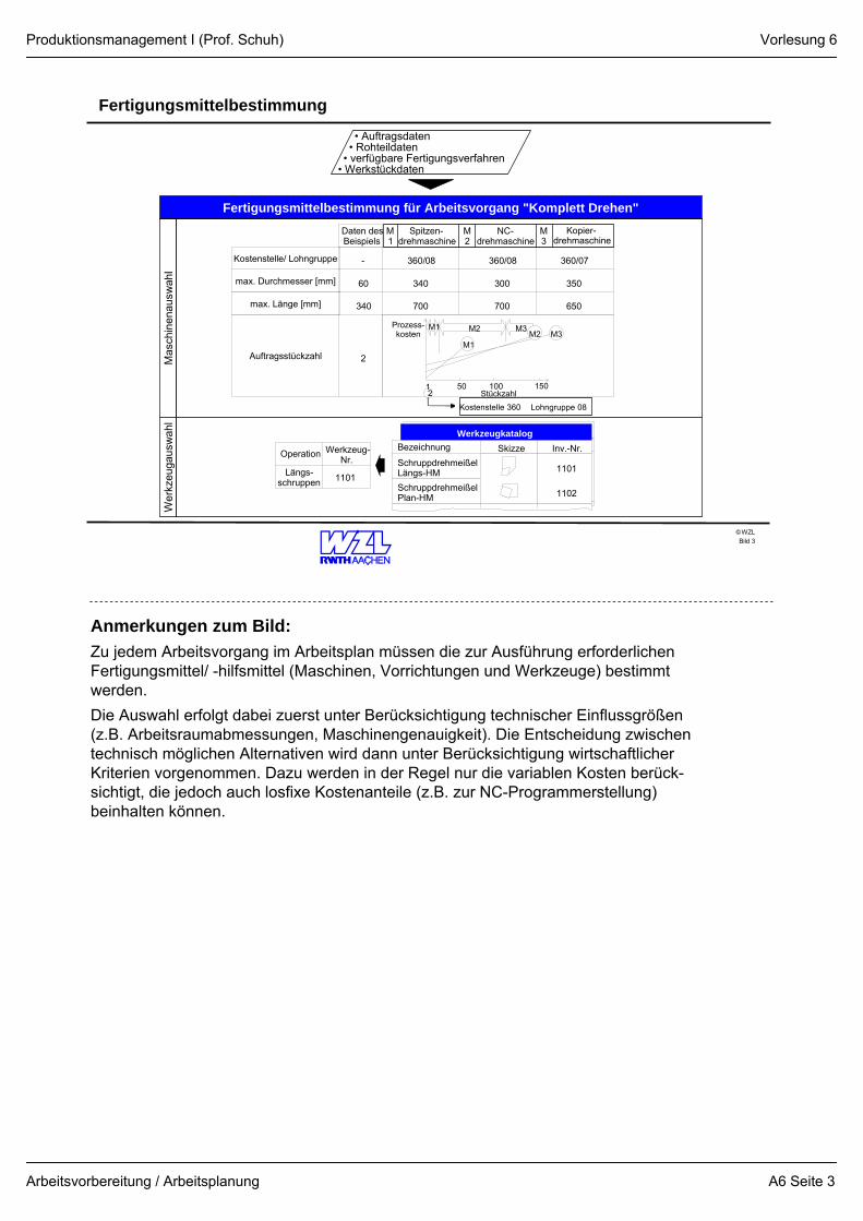
Anmerkungen zum Bild:Zu jedem Arbeitsvorgang im Arbeitsplan müssen die zur Ausführung erforderlichen Fertigungsmittel/ -hilfsmittel (Maschinen, Vorrichtungen und Werkzeuge) bestimmt werden. Die Auswahl erfolgt dabei zuerst unter Berücksichtigung technischer Einflussgrößen (z.B. Arbeitsraumabmessungen, Maschinengenauigkeit). Die Entscheidung zwischen technisch möglichen Alternativen wird dann unter Berücksichtigung wirtschaftlicher Kriterien vorgenommen. Dazu werden in der Regel nur die variablen Kosten berück-sichtigt, die jedoch auch losfixe Kostenanteile (z.B. zur NC-Programmerstellung) beinhalten können.
Vorlesung 6
A6 Seite 3
Produktionsmanagement I (Prof. Schuh)
Arbeitsvorbereitung / Arbeitsplanung
WZL©
Vorgabezeitbestimmung
X = Arbeitsschritt
Arbeitsschritt 3 umfasst Längsdrehen, Fase Drehen, Freistiche Drehen
• Auftragsdaten• Rohteildaten
• verfügbare Fertigungsverfahren• Werkstückdaten
Vorgabezeitbestimmung für den Arbeitsvorgang „Komplett Drehen“
Arbeitsschritte
EinspannenReitstock positionierenrechte Seite komplett DrehenUmspannenStufe Drehen
Verteilzeit (Zv = 12%)Erholzeit (Zer = 8%)Stückzeit (te)
WerkzeugwechselFase rechts DrehenWerkzeugwechselEinstechdrehenAusspannenGesamtGrundzeit
1
Lfd. Nr.
2345678910
0,30
tn(min)
0,151,600,400,300,300,150,300,250,15
th(min)
1,08
0,05
0,03
0,06
3,901,225,120,610,416,14
2. Einspannung
1. Einspannung
Rüstzeit: tr = 4,6 min (Tabellenwert)
Bild 4
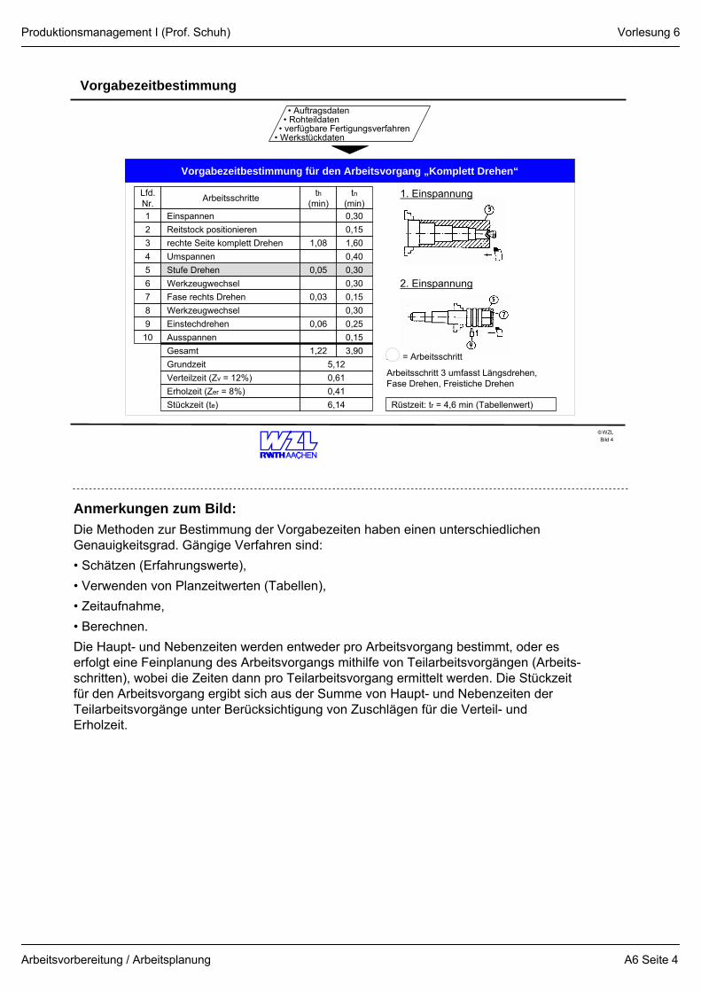
Anmerkungen zum Bild:Die Methoden zur Bestimmung der Vorgabezeiten haben einen unterschiedlichen Genauigkeitsgrad. Gängige Verfahren sind:• Schätzen (Erfahrungswerte),• Verwenden von Planzeitwerten (Tabellen),• Zeitaufnahme,• Berechnen.Die Haupt- und Nebenzeiten werden entweder pro Arbeitsvorgang bestimmt, oder es erfolgt eine Feinplanung des Arbeitsvorgangs mithilfe von Teilarbeitsvorgängen (Arbeits-schritten), wobei die Zeiten dann pro Teilarbeitsvorgang ermittelt werden. Die Stückzeit für den Arbeitsvorgang ergibt sich aus der Summe von Haupt- und Nebenzeiten der Teilarbeitsvorgänge unter Berücksichtigung von Zuschlägen für die Verteil- und Erholzeit.
Vorlesung 6
A6 Seite 4
Produktionsmanagement I (Prof. Schuh)
Arbeitsvorbereitung / Arbeitsplanung
WZL©
Vorgabezeitberechnung eines Teilarbeitsvorgangs
Vorgabezeitberechnung „Stufe-Drehen“
Arbeitsschritte
Anstellen
Stufendrehen (Längsdrehen)
Zurückfahren
Messen
Gesamt
1
Lfd. Nr.
2
3
4
0,10
tn
0,10
0,10
0,30
th
0,05
0,05
Nebenzeittabelle (Kst. 360)
Anstellen
Zurück-fahren
Messen
Längs0,10
50
1,10
Drehoperation
tn (min)
Rücklauf mm
tn (min)
Messlänge mm
tn (min)
Plan
50
0,10
0,12
100
0,11
100
0,11
150
0,12
150
0,12
200
0,13
200
0,13
Schnittwerttabelle Schruppen
Längs-drehen
8,0
0,6
Werkstoff: St50 Schneidstoff: P25
ap (mm)
f (mm)
vc (m/min) 180
Plandrehen
6,0
0,5
160
Hauptzeitberechnung (th):(Formeln siehe Hauptzeittabelle)
th = i =
D = 60; d = 45; L = 30 (Maße aus der Zeichnung)
ap = 7,5; f = 0,6; vc = 180
π*D*L*i D-d f*vc*1000 2*ap
th ≈ 0,05 min{
Bild 5
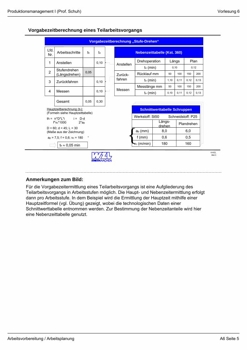
Anmerkungen zum Bild:Für die Vorgabezeitermittlung eines Teilarbeitsvorgangs ist eine Aufgliederung des Teilarbeitsvorgangs in Arbeitsstufen möglich. Die Haupt- und Nebenzeitermittlung erfolgt dann pro Arbeitsstufe. In dem Beispiel wird die Ermittlung der Hauptzeit mithilfe einer Hauptzeitformel (vgl. Übung) gezeigt, wobei die technologischen Daten einer Schnittwerttabelle entnommen werden. Zur Bestimmung der Nebenzeitanteile wird hier eine Nebenzeittabelle genutzt.
Vorlesung 6
A6 Seite 5
Produktionsmanagement I (Prof. Schuh)
Arbeitsvorbereitung / Arbeitsplanung
WZL©
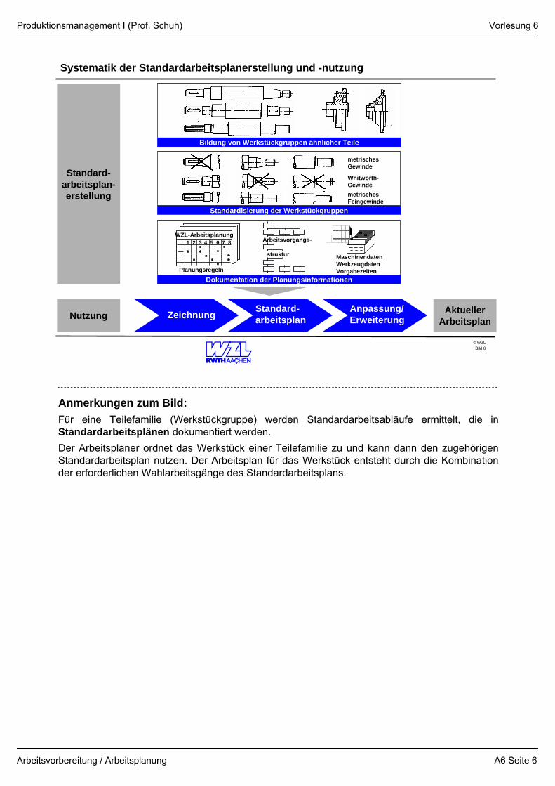
Systematik der Standardarbeitsplanerstellung und -nutzung
Bild 6
Zeichnung Standard-arbeitsplan
Anpassung/Erweiterung
Aktueller ArbeitsplanNutzung
Standard-arbeitsplan-erstellung
Bildung von Werkstückgruppen ähnlicher Teile
Standardisierung der Werkstückgruppen
metrischesGewinde
Whitworth-GewindemetrischesFeingewinde
Dokumentation der Planungsinformationen
WZL-Arbeitsplanung
Planungsregeln
1 2 3 5 6 74 8 Arbeitsvorgangs-
struktur MaschinendatenWerkzeugdatenVorgabezeiten
Anmerkungen zum Bild:Für eine Teilefamilie (Werkstückgruppe) werden Standardarbeitsabläufe ermittelt, die in Standardarbeitsplänen dokumentiert werden.Der Arbeitsplaner ordnet das Werkstück einer Teilefamilie zu und kann dann den zugehörigen Standardarbeitsplan nutzen. Der Arbeitsplan für das Werkstück entsteht durch die Kombination der erforderlichen Wahlarbeitsgänge des Standardarbeitsplans.
Vorlesung 6
A6 Seite 6
Produktionsmanagement I (Prof. Schuh)
Arbeitsvorbereitung / Arbeitsplanung
WZL©
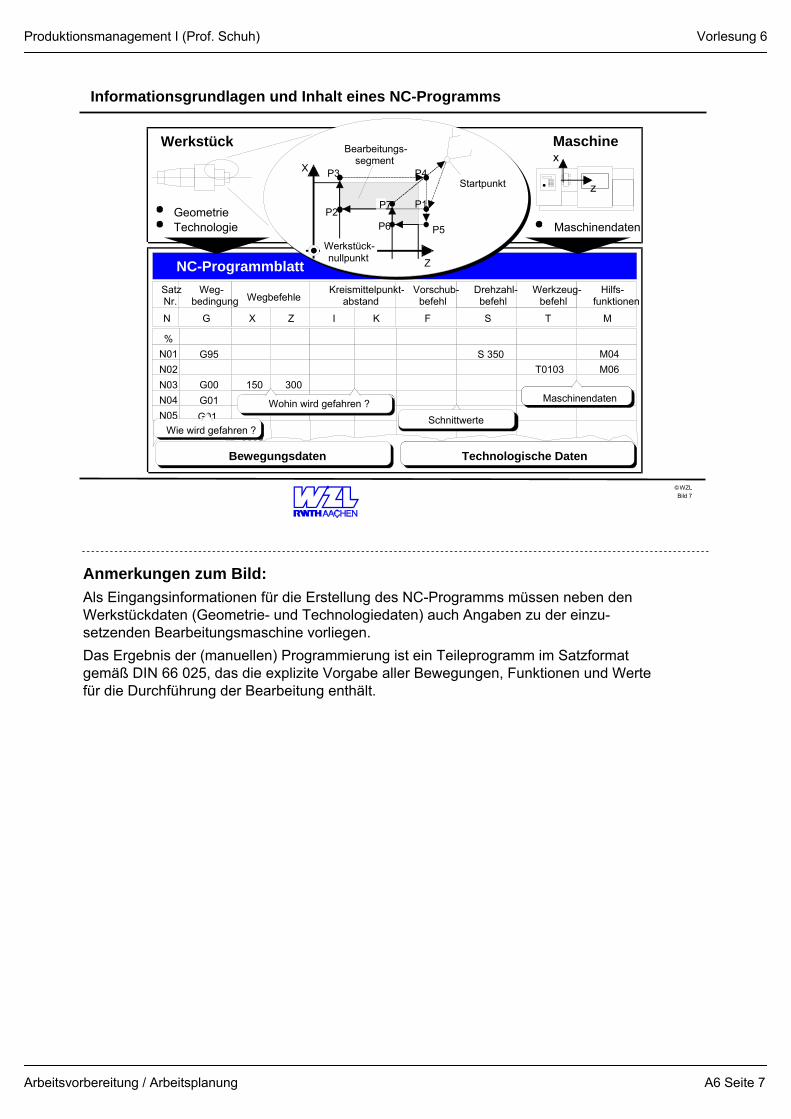
Informationsgrundlagen und Inhalt eines NC-Programms
Bild 7
150
%N01N02N03N04
G95
G00G01
300
S 350 M04T0103 M06
Maschinendaten
N05 G01Wohin wird gefahren ?
Technologische DatenBewegungsdaten
Wegbefehle
MTSFI KX ZN G
NC-Programmblatt
MaschineWerkstück
GeometrieTechnologie Maschinendaten
Hilfs-funktionen
Werkzeug-befehl
Drehzahl-befehl
Vorschub-befehl
Kreismittelpunkt-abstand
Weg-bedingung
SatzNr.
x
z
P2
P3
Z
StartpunktX
Bearbeitungs-segment
Werkstück-nullpunkt
P5
P4
P1P7
P6
6000Wie wird gefahren ?Schnittwerte
Anmerkungen zum Bild:Als Eingangsinformationen für die Erstellung des NC-Programms müssen neben den Werkstückdaten (Geometrie- und Technologiedaten) auch Angaben zu der einzu-setzenden Bearbeitungsmaschine vorliegen.Das Ergebnis der (manuellen) Programmierung ist ein Teileprogramm im Satzformat gemäß DIN 66 025, das die explizite Vorgabe aller Bewegungen, Funktionen und Werte für die Durchführung der Bearbeitung enthält.
Vorlesung 6
A6 Seite 7
Produktionsmanagement I (Prof. Schuh)
Arbeitsvorbereitung / Arbeitsplanung
WZL©
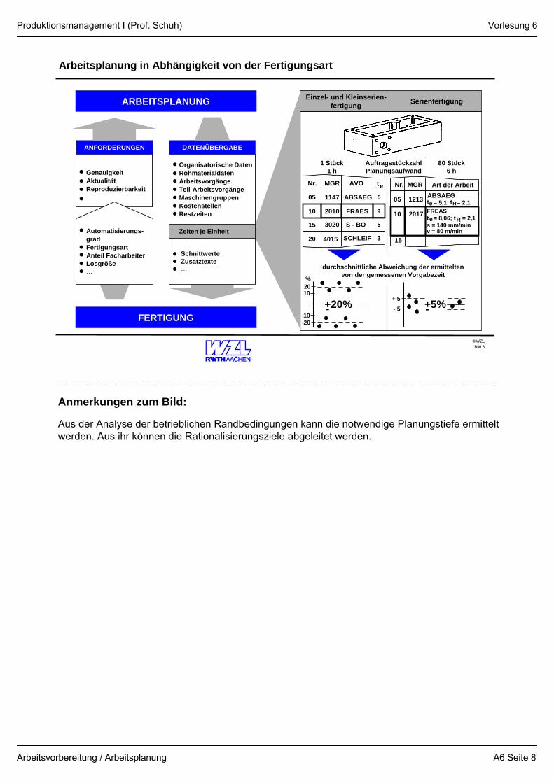
Arbeitsplanung in Abhängigkeit von der Fertigungsart
Bild 8
ARBEITSPLANUNG
GenauigkeitAktualitätReproduzierbarkeit
ANFORDERUNGEN
Organisatorische DatenRohmaterialdatenArbeitsvorgängeTeil-ArbeitsvorgängeMaschinengruppenKostenstellenRestzeiten
DATENÜBERGABE
Zeiten je Einheit
SchnittwerteZusatztexte…
Automatisierungs-gradFertigungsartAnteil FacharbeiterLosgröße…
Einzel- und Kleinserien-fertigung
FERTIGUNG
Serienfertigung
05 1147 ABSAEG 5
10 2010 FRAES 9
15 3020 S - BO 5
Nr. MGR AVO t e
20 4015 SCHLEIF 3
05 1213 ABSAEG= 5,1; = 2,1
10 2017
Nr. MGR Art der Arbeit
te
15
tR
eFREASt = 8,06; t = 2,1s = 140 mm/minv = 80 m/min
durchschnittliche Abweichung der ermitteltenvon der gemessenen Vorgabezeit
2010
-10-20
+20%-
%
+ 5- 5 +5%-
1 Stück1 h
AuftragsstückzahlPlanungsaufwand
80 Stück6 h
R
Anmerkungen zum Bild:
Aus der Analyse der betrieblichen Randbedingungen kann die notwendige Planungstiefe ermittelt werden. Aus ihr können die Rationalisierungsziele abgeleitet werden.
Vorlesung 6
A6 Seite 8
Produktionsmanagement I (Prof. Schuh)
Arbeitsvorbereitung / Arbeitsplanung
WZL©
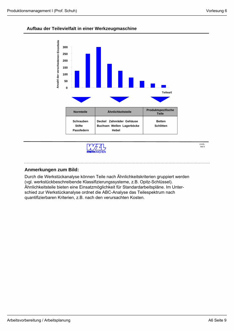
Aufbau der Teilevielfalt in einer Werkzeugmaschine
Bild 9
Anz
ahl d
e r v
e rs c
h ie d
e ne n
Ein
z elte
ile
0
50
100
150
200
250
300
Teileart
Normteile Ähnlichkeitsteile ProduktspezifischeTeile
SchraubenStifte
Passfedern
Deckel Zahnräder GehäuseBuchsen Wellen Lagerböcke
Hebel
BettenSchlitten
Anmerkungen zum Bild:Durch die Werkstückanalyse können Teile nach Ähnlichkeitskriterien gruppiert werden (vgl. werkstückbeschreibende Klassifizierungssysteme, z.B. Opitz-Schlüssel). Ähnlichkeitsteile bieten eine Einsatzmöglichkeit für Standardarbeitspläne. Im Unter-schied zur Werkstückanalyse ordnet die ABC-Analyse das Teilespektrum nach quantifizierbaren Kriterien, z.B. nach den verursachten Kosten.
Vorlesung 6
A6 Seite 9
Produktionsmanagement I (Prof. Schuh)
Arbeitsvorbereitung / Arbeitsplanung
WZL©
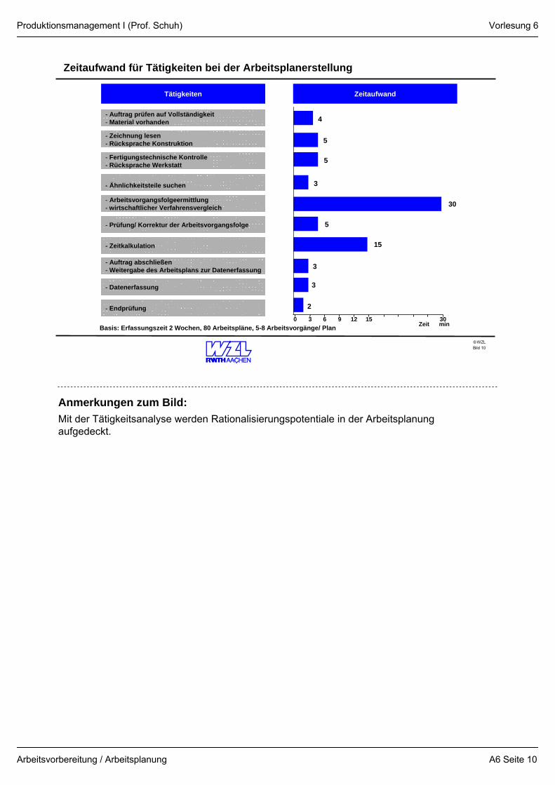
Zeitaufwand für Tätigkeiten bei der Arbeitsplanerstellung
Bild 10
Tätigkeiten
- Zeichnung lesen- Rücksprache Konstruktion
- Fertigungstechnische Kontrolle- Rücksprache Werkstatt
- Ähnlichkeitsteile suchen
- Arbeitsvorgangsfolgeermittlung- wirtschaftlicher Verfahrensvergleich
- Prüfung/ Korrektur der Arbeitsvorgangsfolge
- Zeitkalkulation
- Auftrag abschließen- Weitergabe des Arbeitsplans zur Datenerfassung
- Datenerfassung
- Endprüfung 2
3
3
15
5
30
3
5
5
4
0 3 6 9 12 15 30
Zeitaufwand
Zeit min
- Auftrag prüfen auf Vollständigkeit- Material vorhanden
Basis: Erfassungszeit 2 Wochen, 80 Arbeitspläne, 5-8 Arbeitsvorgänge/ Plan
Anmerkungen zum Bild:Mit der Tätigkeitsanalyse werden Rationalisierungspotentiale in der Arbeitsplanung aufgedeckt.
Vorlesung 6
A6 Seite 10
Produktionsmanagement I (Prof. Schuh)
Arbeitsvorbereitung / Arbeitsplanung
WZL©
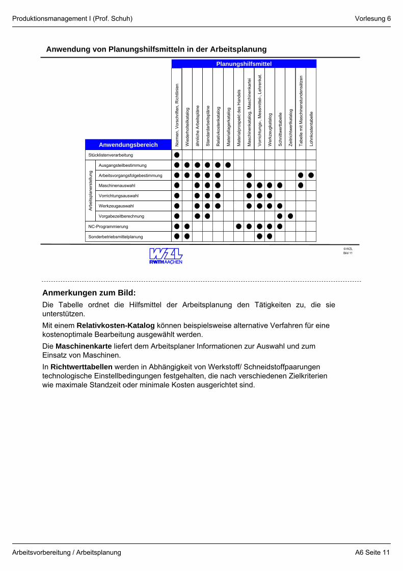
Anwendung von Planungshilfsmitteln in der Arbeitsplanung
Bild 11
Ausgangsteilbestimmung
Arbeitsvorgangsfolgebestimmung
Maschinenauswahl
Vorrichtungsauswahl
Werkzeugauswahl
Vorgabezeitberechnung
NC-Programmierung
Sonderbetriebsmittelplanung
Arb
eits
plan
erst
ellu
ng
Anwendungsbereich Nor
men
, Vor
schr
iften
, Ric
htlin
ien
Wie
derh
olte
ilkat
alog
ähnl
iche
Arb
eits
plän
e
Sta
ndar
darb
eits
plän
e
Rel
ativ
kost
enka
talo
g
Mat
eria
llage
rkat
alog
Mat
eria
lpro
spek
t des
Han
dels
Mas
chin
enka
talo
g, M
asch
inen
karte
i
Vorri
chtu
ngs-
, Mes
smitt
el-,
Lehr
enka
t.
Wer
kzeu
gkat
alog
Sch
nittw
ertta
belle
Zeitr
icht
wer
tkat
alog
Tabe
lle m
it M
asch
inen
stun
dens
ätze
n
Lohn
kost
enta
belle
Planungshilfsmittel
Stücklistenverarbeitung
Anmerkungen zum Bild:Die Tabelle ordnet die Hilfsmittel der Arbeitsplanung den Tätigkeiten zu, die sie unterstützen.Mit einem Relativkosten-Katalog können beispielsweise alternative Verfahren für eine kostenoptimale Bearbeitung ausgewählt werden.Die Maschinenkarte liefert dem Arbeitsplaner Informationen zur Auswahl und zum Einsatz von Maschinen.In Richtwerttabellen werden in Abhängigkeit von Werkstoff/ Schneidstoffpaarungen technologische Einstellbedingungen festgehalten, die nach verschiedenen Zielkriterien wie maximale Standzeit oder minimale Kosten ausgerichtet sind.
Vorlesung 6
A6 Seite 11
Produktionsmanagement I (Prof. Schuh)
Arbeitsvorbereitung / Arbeitsplanung
WZL©
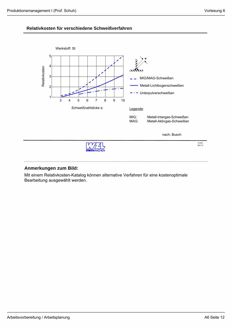
Relativkosten für verschiedene Schweißverfahren
Bild 12
a
3 4 5 6 7 8 9 10
5
4
3
2
1
Schweißnahtdicke a
Rel
ativ
kost
enWerkstoff: St
MIG/MAG-Schweißen
Metall-Lichtbogenschweißen
Unterpulverschweißen
Legende:
MIG: Metall-Intergas-SchweißenMAG: Metall-Aktivgas-Schweißen
nach: Busch
Anmerkungen zum Bild:Mit einem Relativkosten-Katalog können alternative Verfahren für eine kostenoptimale Bearbeitung ausgewählt werden.
Vorlesung 6
A6 Seite 12
Produktionsmanagement I (Prof. Schuh)
Arbeitsvorbereitung / Arbeitsplanung
WZL©
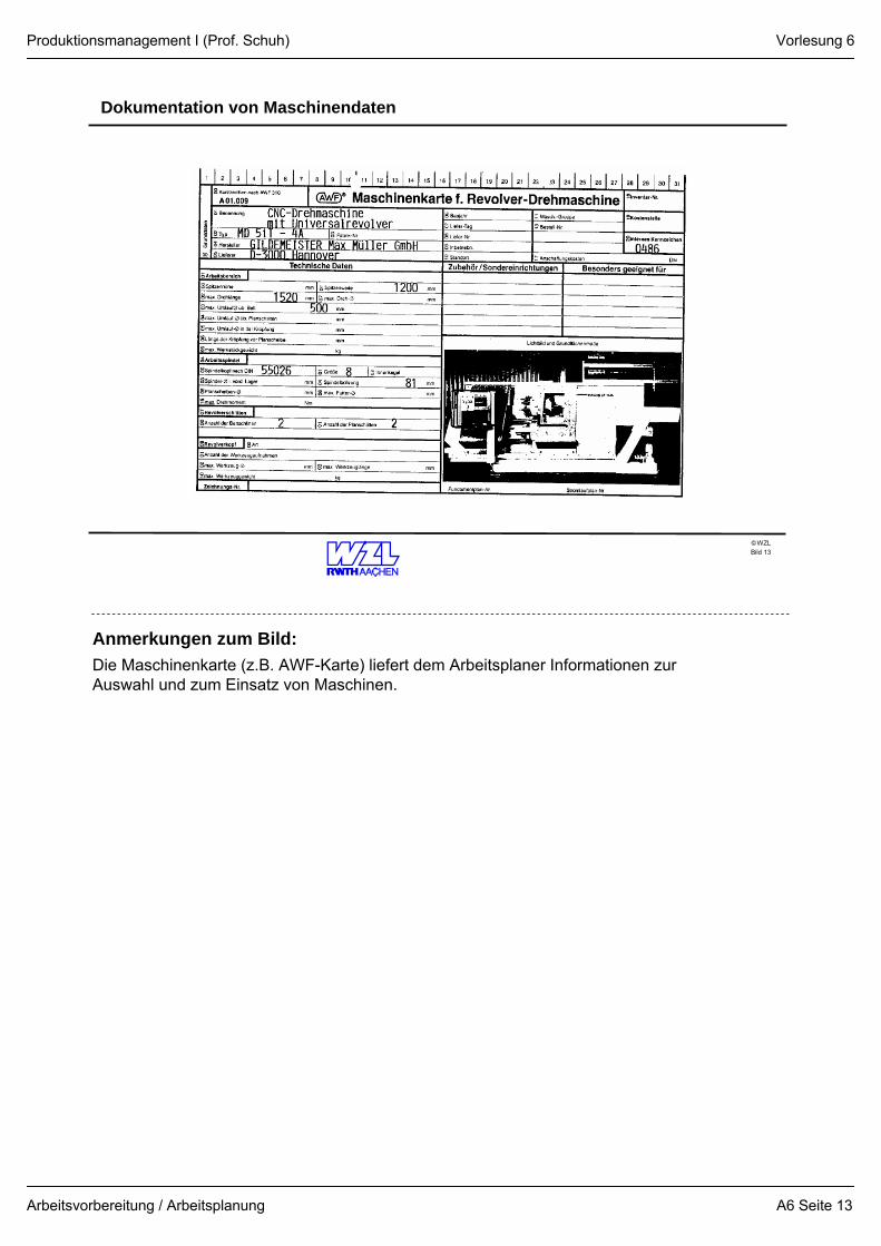
Dokumentation von Maschinendaten
Bild 13
Anmerkungen zum Bild:Die Maschinenkarte (z.B. AWF-Karte) liefert dem Arbeitsplaner Informationen zur Auswahl und zum Einsatz von Maschinen.
Vorlesung 6
A6 Seite 13
Produktionsmanagement I (Prof. Schuh)
Arbeitsvorbereitung / Arbeitsplanung
WZL©
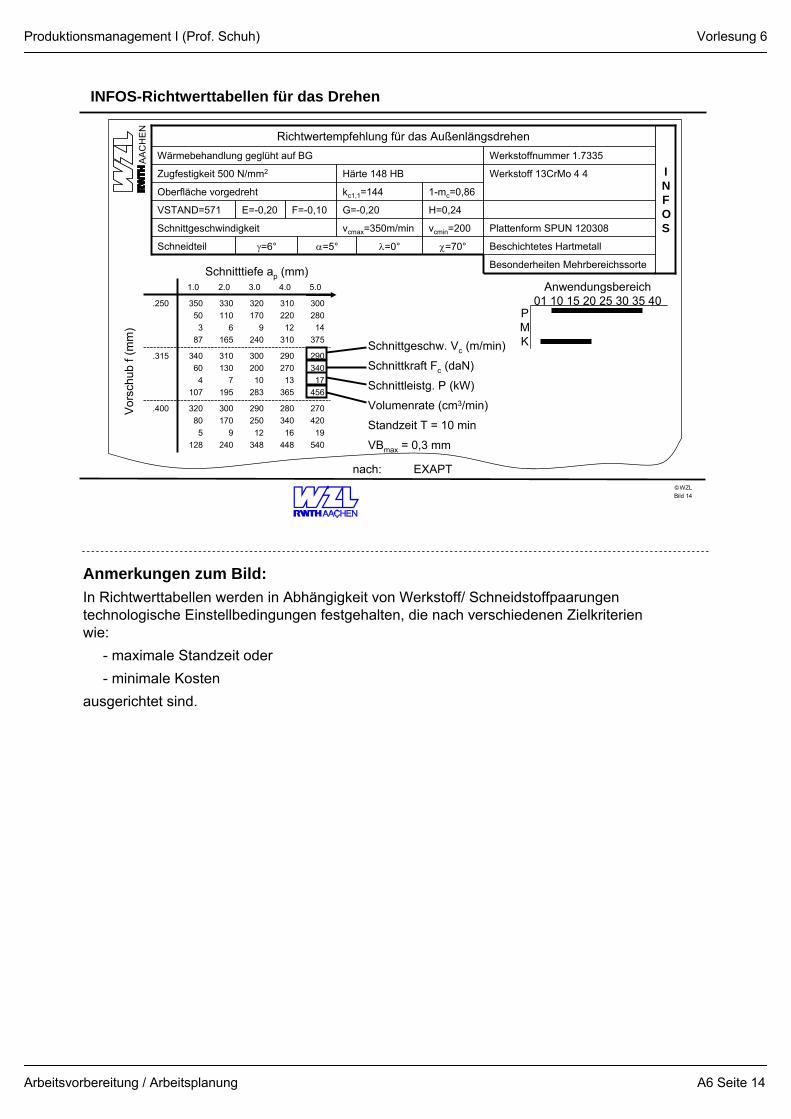
INFOS-Richtwerttabellen für das Drehen
Bild 14
λ=0°γ=6°Schneidteil
Schnittgeschwindigkeit
VSTAND=571
Oberfläche vorgedreht
Zugfestigkeit 500 N/mm2
Wärmebehandlung geglüht auf BG
Richtwertempfehlung für das Außenlängsdrehen
INFOS
Werkstoffnummer 1.7335
Plattenform SPUN 120308vcmin=200vcmax=350m/min
Beschichtetes Hartmetallχ=70°α=5°
E=-0,20
Besonderheiten Mehrbereichssorte
H=0,24G=-0,20F=-0,10
1-mc=0,86kc1,1=144
Werkstoff 13CrMo 4 4Härte 148 HB
AA
CH
EN
27042019
540
29034017
456
30028014
375
5.0
28034016
448
29025012
348
300170
9240
320805
128
.400
29027013
365
30020010
283
310130
7195
340604
107
.315
31022012
310
320170
9240
330110
6165
350503
87
.250
4.03.02.01.0
Schnitttiefe ap (mm)
Vor
schu
b f (
mm
)
nach: EXAPT
Schnittgeschw. Vc (m/min)
Schnittkraft Fc (daN)
Schnittleistg. P (kW)
Volumenrate (cm3/min)
Standzeit T = 10 min
VBmax = 0,3 mm
Anwendungsbereich01 10 15 20 25 30 35 40
PMK
Anmerkungen zum Bild:In Richtwerttabellen werden in Abhängigkeit von Werkstoff/ Schneidstoffpaarungen technologische Einstellbedingungen festgehalten, die nach verschiedenen Zielkriterien wie:
- maximale Standzeit oder- minimale Kosten
ausgerichtet sind.
Vorlesung 6
A6 Seite 14
Produktionsmanagement I (Prof. Schuh)
Arbeitsvorbereitung / Arbeitsplanung
WZL©
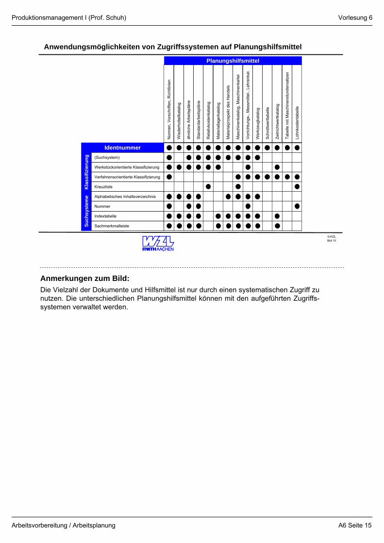
Anwendungsmöglichkeiten von Zugriffssystemen auf Planungshilfsmittel
Bild 15
(Suchsystem)
Werkstückorientierte Klassifizierung
Verfahrensorientierte Klassifizierung
Kreuzliste
Alphabetisches Inhaltsverzeichnis
Nummer
Indextabelle
Sachmerkmalleiste
Kla
ssifi
zier
ung
Identnummer
Such
syst
eme
Nor
men
, Vor
schr
iften
, Ric
htlin
ien
Wie
derh
olte
ilkat
alog
ähnl
iche
Arb
eits
plän
e
Sta
ndar
darb
eits
plän
e
Rel
ativ
kost
enka
talo
g
Mat
eria
llage
rkat
alog
Mat
eria
lpro
spek
t des
Han
dels
Mas
chin
enka
talo
g, M
asch
inen
karte
i
Vorri
chtu
ngs-
, Mes
smitt
el-,
Lehr
enka
t.
Wer
kzeu
gkat
alog
Sch
nittw
ertta
belle
Zeitr
icht
wer
tkat
alog
Tabe
lle m
it M
asch
inen
stun
dens
ätze
n
Lohn
kost
enta
belle
Planungshilfsmittel
Anmerkungen zum Bild:Die Vielzahl der Dokumente und Hilfsmittel ist nur durch einen systematischen Zugriff zu nutzen. Die unterschiedlichen Planungshilfsmittel können mit den aufgeführten Zugriffs-systemen verwaltet werden.
Vorlesung 6
A6 Seite 15
Produktionsmanagement I (Prof. Schuh)
Arbeitsvorbereitung / Arbeitsplanung
WZL©
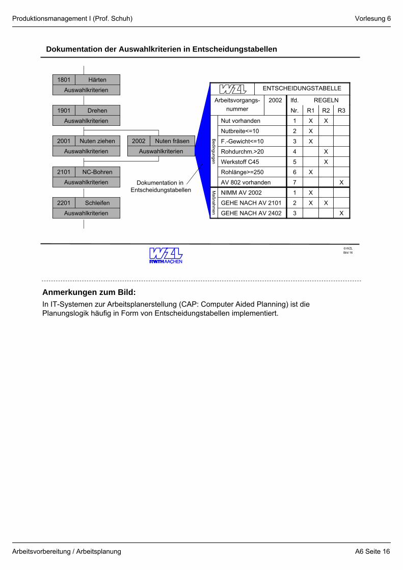
Dokumentation der Auswahlkriterien in Entscheidungstabellen
Bild 16
Auswahlkriterien
Härten1801
Auswahlkriterien
NC-Bohren2101
Auswahlkriterien
Drehen1901
Auswahlkriterien
Nuten ziehen2001
Auswahlkriterien
Nuten fräsen2002
Auswahlkriterien
Schleifen2201
XX1Nut vorhanden
Bedingungen
R3R2R1Nr.
X2Nutbreite<=10
X3F.-Gewicht<=10
X4Rohdurchm.>20
X6Rohlänge>=250
X5Werkstoff C45
REGELNlfd.2002Arbeitsvorgangs-nummer
ENTSCHEIDUNGSTABELLE
XX
X
X3GEHE NACH AV 2402
2GEHE NACH AV 2101
1NIMM AV 2002M
aßnahmen
X7AV 802 vorhandenDokumentation in Entscheidungstabellen
Anmerkungen zum Bild:In IT-Systemen zur Arbeitsplanerstellung (CAP: Computer Aided Planning) ist die Planungslogik häufig in Form von Entscheidungstabellen implementiert.
Vorlesung 6
A6 Seite 16