Embed Size (px)
Citation preview
The 3rd IEAGHG Technical Workshop on HTSLC in Vienna 1
Process Integration of Ca-Looping Process with a Cement Manufacturing Plant
Hyungwoong Ahn, Dursun Can Ozcan, Stefano Brandani
Institute for Materials and ProcessesSchool of Engineering
University of Edinburgh2011/08/30

The 3rd IEAGHG Technical Workshop on HTSLC in Vienna 2
Carbon Capture for Cement Industy
CO2 Emission from Cement Industy• Large industrial source of CO2 emission (5% of worldwide emission)• The CO2 emission rate is around 0.72 – 0.98 ton CO2/ ton cement• Over 60% of the total emission accounts for mineral dissociation. The reduction
of CO2 emission by improving its energy efficiency is highly limited.)
Technical Options for Carbon Capture • Oxy-combustion
Limited CO2 product purity (80 v%) due to infiltration air CO2 purification required.• Post-combustion amine process
CO2 vol.% is as high as 20-30% and MEA is saturated with CO2 below this CO2 level. Stripper steam should be generated with an external boiler. new boiler, FGD, SCR
• Post-combustion Ca-looping process The absorbent is one of the cement raw materials purge CaO can be used for
cement manufacture. The operating condition of a carbonator can be found in cement plant. No pre-
conditioning of feed stream is required.

The 3rd IEAGHG Technical Workshop on HTSLC in Vienna 3
Chemical Reactions
Ref. Cement Chemistry, H F W Taylor, 2nd ed. 1997.
Reaction ∆H (kJ) For 1kg of
CaCO3 (Calcite) CaO + CO2(g) +1782 CaCO3
AS4H (pyrophyllite) α-Al2O3 + 4SiO2(quartz) + H2O(g) +224 AS4H
AS2H2 (kaolinite) α-Al2O3 + 2SiO2(quartz) + 2H2O(g) +538 AS2H2
2FeO⋅OH (goethite) α-Fe2O3 + H2O(g) +254 FeO⋅OH
2CaO + SiO2 (quartz) ß-C2S -734 C2S
3CaO + SiO2 (quartz) C3S -495 C3S
3CaO + α-Al2O3 C3A -27 C3A
6CaO + 2 α-Al2O3 + α-Fe2O3 C6A2F -157 C6A2F
4CaO + α-Al2O3 + α-Fe2O3 C4AF -105 C4AF
The enthalpy of formation of 1kg of a Portland cement clinker is around +1757 kJ/kg and the total heat requirement in dry process kiln is around 3306 kJ/kg clinker.

The 3rd IEAGHG Technical Workshop on HTSLC in Vienna 4
Phase Change in Cement Plant
Ref. Cement Chemistry, H F W Taylor, 2nd ed. 1997.
Pre-heaters • Partial CaCO3 calcination• Partial clay minerals
decomposition
Pre-calciner• CaCO3 calcination (>90%) and
clay mineral decomposition completed.
• Partial conversion of CaO to C2S.
Kiln• C2S to C3S conversion. C3A and
C4AF formed. (The Bogue calculation)
• Aluminate and Ferrite melting.
Preheaters out
Pre-Calciner Kiln

The 3rd IEAGHG Technical Workshop on HTSLC in Vienna 5
Base Case Simulation
• Steady-state process simulation by Honeywell Unisim R390.
Comparison of heat loss in a cement plant [kJ/kg clinker]Heat loss by radiation and
convectionThis
study Reference
Preheater 35 40
Calciner 22 20
Rotary Kiln 253 237
Tertiary air duct 27 27
Cooler+kiln hood 30 14
Total 367 338
Ref. VDZ, Execution and Evaluation of Kiln Performance Tests, 1992, Ali et al., 2010.
* Net heat of melting is around 104.7 kJ/kg.
-1.25E+06
-1.20E+06
-1.15E+06
-1.10E+06
-1.05E+06
-1.00E+060 200 400 600 800 1000 1200 1400 1600 1800 2000
Temperature [K]
Enth
alpy
[J/m
ol]
Comparison of CaCO3 enthalpies between reference and Unisim simulation.

The 3rd IEAGHG Technical Workshop on HTSLC in Vienna 6
Carbonate Looping Process
• Calciner needs to operate at 930oC for 100% calcination while carbonator operates at 600 – 750 oC
• CaO loses its capacity over the cycles a theoretical capture rate is determined by two flowrate ratios: FR/FCO2 and FO/FCO2.
• Purge can be utilized in the cement industry as long as the cement spec is met. (CaSO4 limit: 10 wt.%, Ash limit: 30 wt.%)
• The heat of reaction for calcination (–175 kJ/mol) is higher than amine process (–154 kJ/mol for MEA) but the exothermic heat can be recovered by steam cycle (electricity).

The 3rd IEAGHG Technical Workshop on HTSLC in Vienna 7
0
200400
600
800
10001200
1400
1600
Tem
pera
ture
[C]
Selection of an Optimal Feed Stream for Ca-looping Process
Raw Mill 1st Preheater 2nd Preheater 3rd Preheater 4th Preheater Pre-Calciner Kiln Cooler
Gas Flow
Solid Flow
Raw Mill 1st Preheater
2nd Preheater
3rd Preheater
4th Preheater Pre-Calciner Kiln Cooler
Bag Filter Bag FilterFuel Drying
Bag Filter
CoalPet Coke
Air In-leak Air In-leak Air In-leak Air In-leak Air In-leak Air In-leak
Secondary Air
Cooling Air
Tertiary Air
Primary Air
Raw MealClinker
Collected Dust
Air In-leak
To Atmosphere
To Atmosphere
To Atmosphere
Flue gas temperature is around 650°C no preheating is required.Higher CO2 concentration,
Flue gas needs to be heated up to 650°C. Relatively low CO2concentration.

The 3rd IEAGHG Technical Workshop on HTSLC in Vienna 8
Process Integration in Retrofit Case
1) The flue gas from the 3rd Preheater is diverted to a Ca-looping process for carbon capture.
2) CO2 depleted flue gas from the carbonator is routed to the 2nd Preheater for the raw material preheating.
3) Part of excess air from the cooler is used for additional raw material heating.4) Purge from the carbon capture calciner is sent to the kiln. the required
amount of fuel for the kiln needs to be increased.
Raw Mill 1st Preheater
2nd Preheater
3rd Preheater
4th Preheater Pre-Calciner Kiln Cooler
Bag Filter Bag Filter
Fuel Drying
Bag Filter
CoalPet Coke
Air In-leak Air In-leak Air In-leak Air In-leak Air In-leak Air In-leak
Secondary Air
Cooling Air
Tertiary Air
Primary Air
Raw MealClinker
Collected Dust
Air In-leak
To Atmosphere
To Atmosphere
To Atmosphere
Carbonator Calciner
CaCO3
CaO
Coke
CO2 Compression
Oxygen
CaCO3 M/U
Steam Cycle CompressedCO2
Purge
Raw Material
Pre-heater

The 3rd IEAGHG Technical Workshop on HTSLC in Vienna 9
Carbonator Model
1-D Fast Fluidisation Model in CFB
1) Particle Distribution (Lean/Dense Region) • The volume fraction of solids in a
dense region is fixed.2) Carbonation Reaction Rate
• Calculation of active CaO fraction.• Calculation of carbonation rate in
terms of boundary layer diffusion and chemical reaction.
3) CO2 absorption efficiency• Implemented Matlab code into
Unisim Design Suit R390 through a COM interface
0
20
40
60
80
100
0 10 20Cap
ture
Eff
icie
ncy
(%)
Height (m)
Unisim User Unit Operation for Carbonator Simulation
Carbonator Simulation Result

The 3rd IEAGHG Technical Workshop on HTSLC in Vienna 10
Carbonator Model
Parameters for the carbonator model FCO2: 200 kmol/h, FCaO: 325 kmol/h, uo: 6m/s
80828486889092949698
100
575 600 625 650 675 700 725
Cap
ture
Eff
icie
ncy
(%)
Temperature (oC)
0
50
100
150
200
250
6000 7000 8000 9000 10000 11000
Pres
sure
Dro
p (m
bar)
Solid Inventory (kg)
0
5
10
15
20
0 0.1 0.2
Hei
ght (
m)
Solid Fraction
Solid Inventory6600 kg
80828486889092949698
100
500 1000 1500 2000 2500
Cap
ture
Eff
icie
ncy
(%)
FCaO in the purge (kgmole/h)
Results of parametric study on carbonator model

The 3rd IEAGHG Technical Workshop on HTSLC in Vienna 11
Simulation – Retrofit Case
Simulation Basis• Target: 90% CO2 recovery and 95+% CO2 purity.• ASU : 95% O2 purity.• CO2 product is compressed up to 150 bar. • The flowrates of both CaO circulation and CaCO3 make-up were determined
such that FR/FCO2 = 3.9 and FO/FCO2 = 0.1 in order to accomplish 90% CO2
capture.• 10% excess oxygen is fed to the calciner for complete combustion.

The 3rd IEAGHG Technical Workshop on HTSLC in Vienna 12
Steam Cycle and CO2 Compression
Ref. Cement Chemistry, H F W Taylor, 2nd ed. 1997.14 Rodriguez et al., 2009; 15 Rodriguez et al., 2010
Sub-critical Rankine cycle• Heat source: Heat extracted from
the carbonator and heat from a hot CO2 stream from the calciner
• Steam cycle efficiency: 35%
CO2 Compression• Multistage Turbo Compressor with
intermediate cooling.• Inlet temperatures were fixed as
45oC.• Adiabatic efficiency of each
compressor is 85%.
The 3rd IEAGHG Technical Workshop on HTSLC in Vienna 13
Simulation Results – Retrofit Case
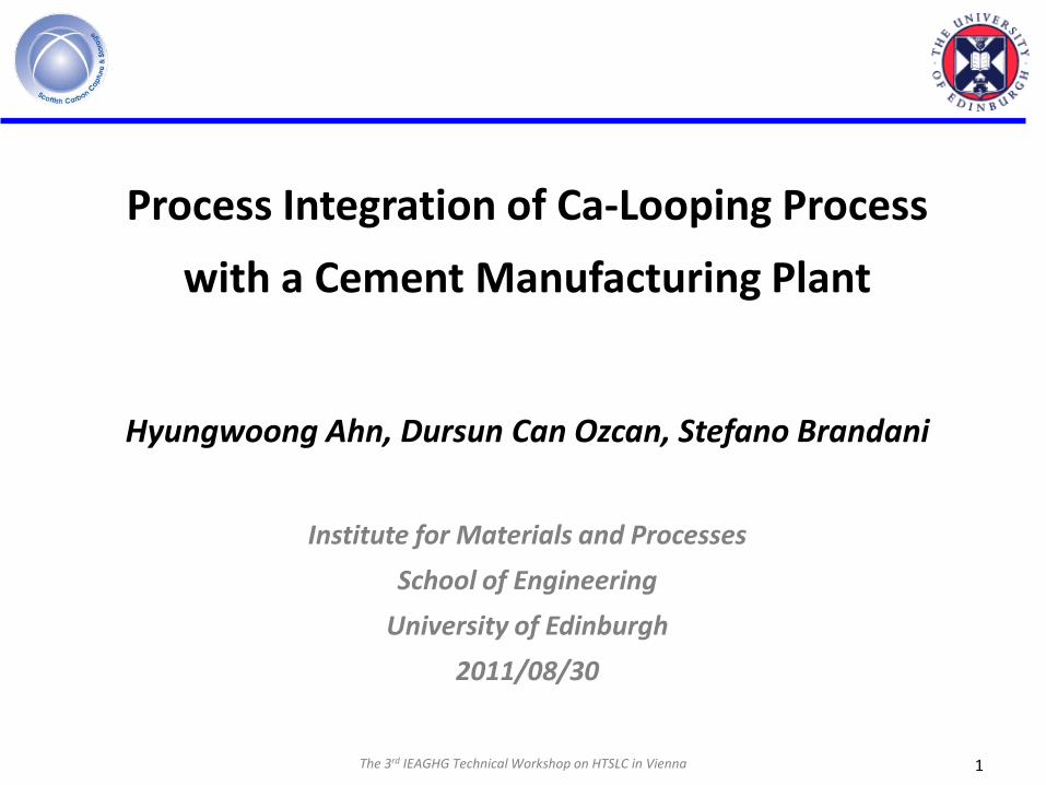
Simulation Result
Base Case Retrofit Case
Raw Meal [kg/s] 52.4 52.4 + 5.8
Clinker Product [kg/s] 31.6 34.8
Energy input per kg of clinker [kJ/kg] 3,081 7,221
CO2 emitted per kg of clinker [kg/kg] 0.806 0.075
Gross power generation [MWe] N/A 50
Energy consumption in CO2 compression [MWe] N/A 15
*Energy consumption in ASU [MWe] N/A 10
Energy consumption per kg of captured CO2 [kJ/kg] N/A 3,527*ASU power consumption : 200 kWh/ton O2.
• Energy consumption per unit mass of clinker in retrofit case is more than double that in base case.
• The required electricity for CO2 compression and ASU can be produced by a steam cycle being driven by the heat recovery from Ca-looping process.

The 3rd IEAGHG Technical Workshop on HTSLC in Vienna 14
Conclusions
• Cement process has been successfully simulated by a steady-state process simulator considering typical chemical reactions. The simulation will be refined to reflect a more detailed reactions.
• A User Unit Operation for 1-D Carbonator has been developed in order to estimate its CO2 capture rate and the dimension of reactor. Develop user defined unit operations for calciner and kiln.
• Optimal feed stream for carbon capture Ca-looping process was selected as 3rd
preheater outlet based on the feed temperature and COz concentration.• The heat from the flue gas leaving the carbonator is integrated with cement
plant by feeding it to 2nd preheater.• The purge of deactivated CaO can be mixed with calcined material from pre-
calciner and sent to the kiln. Increasing the production by approximately 10 %. need to determine the optimums of the two flowrate ratios: circulating CaO to CO2 and CaCO3 make-up to CO2.

The 3rd IEAGHG Technical Workshop on HTSLC in Vienna 15
Conclusions
• Steam cycle has been simulated independently to estimate the power generation by heat recovery Investigate the further integration with steam cycle. Need a detailed air separation unit simulation for the estimation of the utilities consumption.
• The required energy for unit clinker in retrofit case is more than double that in base case but additional electricity can be generated. Full comparison with amine and oxyfuel (Unisim flowsheets from IGSCC project), Economic analysis for the evaluation of various capture processes.