Embed Size (px)
Citation preview
Process heat transfer
Double pipe heat exchanger
Group members:
Sannan salabat butt (2007-CHEM-19)
Harris mehmood khan (2007-CHEM-99)
Discussion
�Double pipe heat exchanger
�Internal parts
�Diagrams
�Flow arrangements
�Calculations for L.M.T.D
� Advantages
� Limitations
� Comparison with conventional shall
and tube heat exchanger
� Design types
� Cost estimation
� Numerical problems

HEAT EXCHANGER:
Heat exchanger is a device in which two fluid streams , one hot & another cold are brought into ‘’ thermal contact
‘’ in order to effect transfer of heat from the hot fluid
stream to the cold.
DOUBLE PIPE HEAT EXCHANGER:
A typical double pipe heat exchanger basically consists
of a tube or pipe fixed concentrically inside a larger pipe
or tube.
OR
Heat exchanger which are used when the flow rates of
the fluids and the heat duty are small (less than 500 kW)
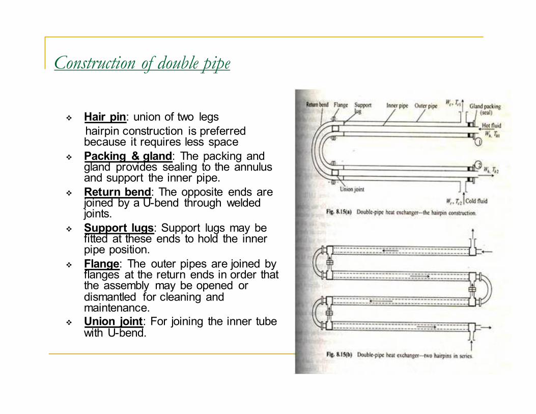
Construction of double pipe
� Hair pin: union of two legs
hairpin construction is preferred because it requires less space
� Packing & gland: The packing and gland provides sealing to the annulus and support the inner pipe.
� Return bend: The opposite ends are joined by a U-bend through welded joints.
� Support lugs: Support lugs may be fitted at these ends to hold the inner pipe position.
� Flange: The outer pipes are joined by flanges at the return ends in order that the assembly may be opened or dismantled for cleaning and maintenance.
� Union joint: For joining the inner tube with U-bend.

Contd….
� Nozzles: small sections of pipes welded to the shell or to the
channel which acts as the inlet or outlet of the fluids are called nozzles.
� Gaskets: Gaskets are placed between the two flanges to make the joint leak-free.
� Different types of gasketsNitrile rubber. Used up to 110 oC for mineral oils, dilute
mineral acids, and aliphatic hydrocarbons.
EPDM.
(ethylene-propylene-diene monomer)
Used up to 160 oC for mineral acids, or bases,
aqeuous solutions or steam
Viton.
( copolymer of vinylidine flouride and
hexafluoro-propylene)
Used up to 100 oC for hydrocarbons and
chlorinated hydrocarbons

Double Pipe Heat Exchangers

fluid flow passages & configuration
Basically there are two flow arrangements of double pipe heat exchanger:
� Co-current� Counter current
configuration
� Series & parallel arrangement
Co-current counter current

� Counter current
� max. heat transfer within minimum area due to more L.M.T.D
� Co-current
� Used for viscous fluids & gives lesser value of L.M.T.D
� Co & counter current gives same value of L.M.T.D if one of the fluid stream is isothermal (e.g steam)
� Series-parallel arrangement
This configuration is used when value of pressure exceeds its limits (500psig shell side and 500 psig tube side) .pressure drop problem can be solved by:
� Reversing the location of streams
� By-passing one of the fluid streams
� Dividing of stream at higher pressure drop( series-parallel arrag.)

CO CURRENT FLOW
∆
∆
∆−∆=∆
1
2
12
lnT
T
TTTLn
731TTTTT
in
c
in
h−=−=∆
1062TTTTT
out
c
out
h−=−=∆
COUNTER CURRENT FLOW
1062TTTTT
in
c
out
h−=−=∆
731TTTTT
out
c
in
h−=−=∆
T1T2
T4 T5
T3
T7 T8 T9
T10
T6
Counter - Current Flow
T1 T2T4 T5
T6T3
T7
T8 T9
T10
Parallel Flow
Log Mean Temperature evaluation
T 1
A
1 2
T2
T3
T6
T4 T6
T7
T8
T9
T10
Wall∆T1
∆ T2
∆ A
A
1 2

ADVANTAGES….
� Compactness
� Very high heat transfer coefficients on both sides of the exchanger
� Close approach temperatures in counter-current flow
� Ease of maintenance.
� Heat transfer area can be added or subtracted with out complete dismantling the equipment.
� High pressure ranges
(30 MPa shell side , 140 MPa tube side)
� High temperatures range
(600 C)

� Approach temperature: for counter flow arrangement the
approach is the number of degrees temperature between
the hot fluid inlet and the cold fluid outlet (T1-t2) or hot
fluid outlet & cold fluid inlet (T2-t1)whichever is small.
similar term is
� Range of temperature: The actual temperature rise or
fall for the hot fluid(T1-T2) & the cold fluid (t2-t1)
CONTD…..
� Ease of inspection on both sides
� Ease of cleaning
� Low cost
� No Local over heating and possibility of stagnant
zones is also reduced
� Fouling tendency is less
� low pressure loss
� Used for small applications

LIMITATIONS
� It is not as cost effective as most shell and tube
exchangers
� It requires special gaskets
� Limited volumetric capacity
� Fouling?

Contd..
Fouling :formation of a scale or a deposit on a heat transfer surface is called fouling
Types of fouling:
� Precipitation fouling ( due to dissolved salts of Ca & Mg )
� Particulate fouling( due to suspended particles )
� Corrosion fouling
� Chemical reaction fouling (due to deposits formed by chemical reactions)
� Bio fouling ( due to the attachment of bio chemical species )
� Solidification fouling ( due to sub cooling of fluids )

Comparison with shell & tube heat exchanger
shell & tube heat exchangers are:
� designed to withstand the greatest temperature andpressure condition
� Ideal for large scale applications
� Commonly used in petrochemical industry where
dangerous substances are present (protective
shell)
� Consists of very bulky or heavy construction, baffles are used to increase mixing
� Subject to water hammer and corrosion
� High pressure loses

Design types
In case of any design equipment , the design of a heat exchanger may be divided into two parts.
Process design Mechanical design
(Thermal design)
� Estimation of heat transfer area. Material of construction
� Determination of tube diameter. Thickness of tubes
� Number & length of tubes. Flanges, gaskets, support design
� Tube layout ( series or parallel )
� Shell & tube side pressure drops.(hydraulic design)
.
Designtypes

Mechanical design
Double pipe Heat exchangers
can be made with various materials:
� Carbon steel
� Alloy steels
� Copper alloys
� Exotic materials (tantalum)

Cost of heat exchanger
� Some of the major factors which influence the cost of heat
exchanger are :
� Heat transfer area
� Tube diameter and thickness
� Tube length
� Pressure of fluids
� Materials of construction
� Special design features ( finned surface,U-bends,removeable
bundles e.t.c )


DESIGN STEPS WITH SOLVED
EXAMPLE
1)Thermal design.
2) Hydraulic design.

ASSUMPTIONS
� The heat exchanger operates under steady state
conditions.
� No phase change occurs: both fluids are single phase and are unmixed.
� Heat losses are negligible
� The temperature in the fluid streams is uniform over
the flow cross section.
� There is no thermal energy source or sink in the heat
exchanger.
� The fluids have constant specific heats.
� The fouling resistance is negligible.

In thermal design we tabulate physical
properties of:
hot stream(Benzene)
cold stream(Water)

� Benzene(hot stream)� entering temp.= 75°C
� Leaving temp.=50°C
� average temp=62.5°C
� Sp.heat=1.88 kJ/kg °C
� Viscosity=0.37cP
� density = 860 kg./m3
� thermal conductivity = 0.154 W/m K.
� Flow rate = 1000 Kg/hr
� outer pipe spec.� i.d. = 41 mm
� o.d. = 48 mm.
� LMTD = ?
� Uo = ?
� Water(cold stream)� entering temp.= 30°C
� Leaving temp.=40°C
� average temp=35°C
� Sp.heat=4.187 kJ/kg °C
� Viscosity=0.8cP
� density = 1000 kg./m3
� thermal conductivity = 0.623 W/m K.
� Flow rate = ?
� Inner tube spec.� i.d=21mm
� O.d=25.4mm
� Wall thickness=2.2mm
� thermal conductivity of wall=74.5 W/m K.
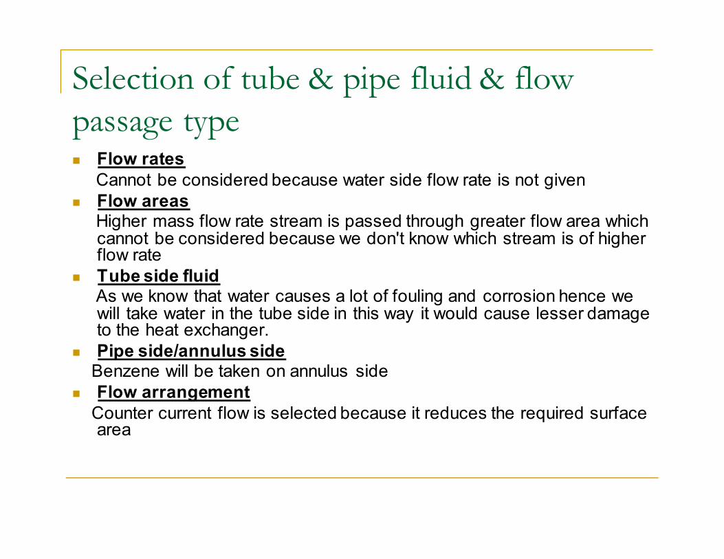
Selection of tube & pipe fluid & flow
passage type� Flow rates
Cannot be considered because water side flow rate is not given
� Flow areasHigher mass flow rate stream is passed through greater flow area which cannot be considered because we don't know which stream is of higher flow rate
� Tube side fluidAs we know that water causes a lot of fouling and corrosion hence we will take water in the tube side in this way it would cause lesser damage to the heat exchanger.
� Pipe side/annulus sideBenzene will be taken on annulus side
� Flow arrangement
Counter current flow is selected because it reduces the required surface area

General design equation & steps
Q =Uo A (∆T)
� Step 1: Calculate (∆T) LMTD
� Step 2: Calculate heat duty Q
� Step 3: Calculate overall heat transfer co-efficient on the
basis of outer diameter of tube
� Putting all the three values will give us the required heat transmission area of double pipe.
� Such a problem in which we have to calculate size of
heat exchanger is called sizing problem

Calculation of LMTD (step 1)
benzene 75 C 50 C
water 40 C 30 C
∆t1=75-40=35°C ∆t2=50-30=20°C
L.M.T.D= (∆t1- ∆t2) / Ln (∆t1/ ∆t2)
LMTD =(35 – 20)/Ln(35/20)
= 26.8°C

Heat duty calculations(step 2)
� SOLUTION
(a) 1000 kg of benzene is cooled from 75°C to 50°C per hour.
Therefore,
Heat duty (Q) = m Cp (T2-T1)
= (1000 kg,/h)(1.88 kJ/kg °C)(75 – 50)°C
= 47,000 kJ/h
Heat given by the hot stream = Heat taken by the cold stream
Water is heated from 30°C to 40°C Therefore,
Water flow rate = Q / Cp x (t2-t1)
= 47000/(4187)(10)
=1122 kg/h

overall heat transfer co-efficient(step 3)
� Calculate convective heat transfer coefficient
for tube side (hi).
� Calculate convective heat transfer coefficient
for shell side (ho).
� Outside surface area of tube (Ao)
� Inside surface area of tube (Ai )
� Mean surface area (Am)
� 1/Uo=1/ho +(Ao/Am)x(ro-ri/kw)+Ao/Ai(1/hi)
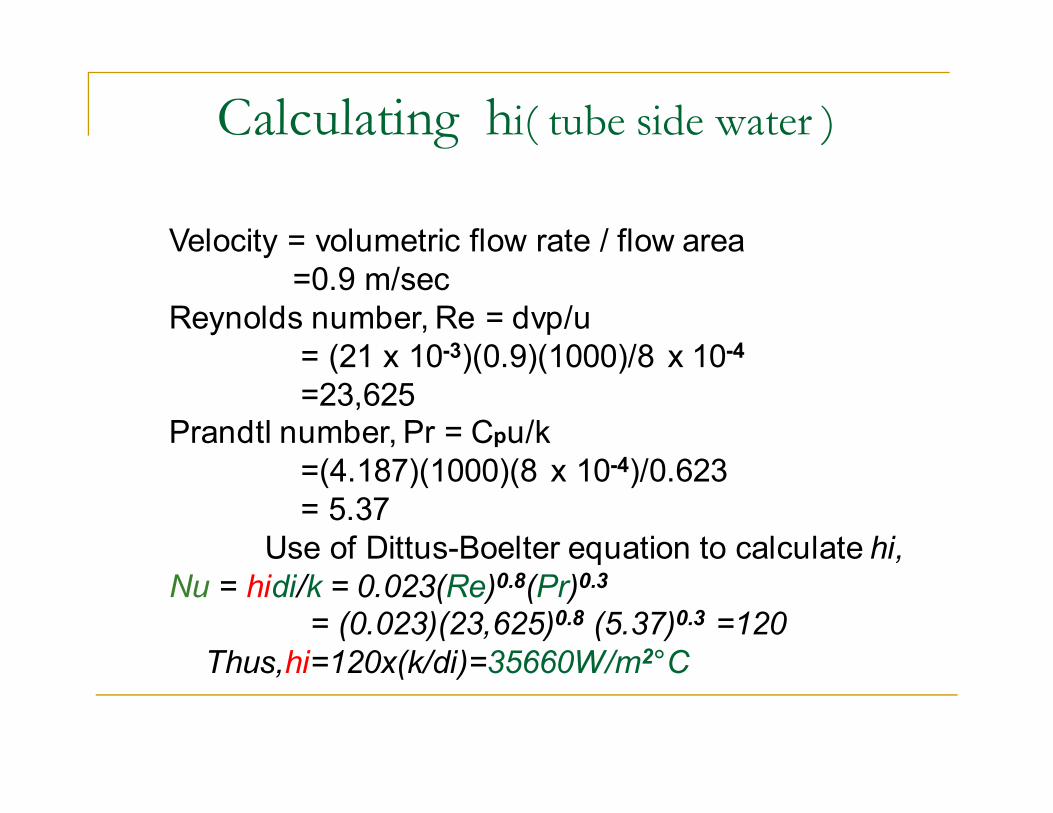
Calculating hi( tube side water )
Velocity = volumetric flow rate / flow area
=0.9 m/sec
Reynolds number, Re = dvp/u
= (21 x 10-3)(0.9)(1000)/8 x 10-4
=23,625Prandtl number, Pr = Cpu/k
=(4.187)(1000)(8 x 10⁻⁴)/0.623
= 5.37
Use of Dittus-Boelter equation to calculate hi,
Nu = hidi/k = 0.023(Re)0.8(Pr)0.3
= (0.023)(23,625)0.8 (5.37)0.3 =120
Thus,hi=120x(k/di)=35660W/m2°C

Calculating ho( annulus side benzene )for annulus calculation we calculate hydraulic diameter
Flow area annulus = inner cross-section of the pipe - outer cross-section of the tube
= Pi/4(iD2) - Pi/4(OD1)=8.13x10-4 m2
wetted perimeter= Pi(iD2+OD1)=0.2086m
hydraulic diameter of annulus dh=4 x ( flow area/wetted perimeter)
=0.0156m
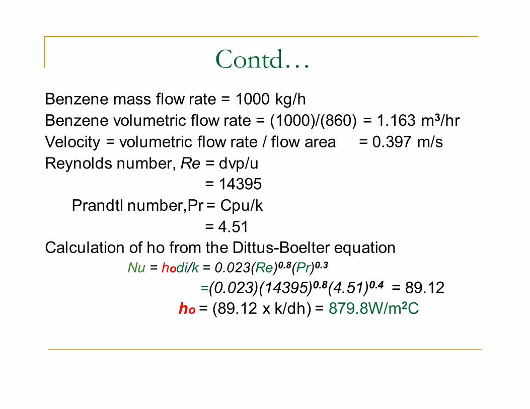
Contd…
Benzene mass flow rate = 1000 kg/h
Benzene volumetric flow rate = (1000)/(860) = 1.163 m3/hr
Velocity = volumetric flow rate / flow area = 0.397 m/s
Reynolds number, Re = dvp/u
= 14395
Prandtl number,Pr = Cpu/k
= 4.51
Calculation of ho from the Dittus-Boelter equation
Nu = hodi/k = 0.023(Re)0.8(Pr)0.3
=(0.023)(14395)0.8(4.51)0.4 = 89.12
ho = (89.12 x k/dh) = 879.8W/m2C
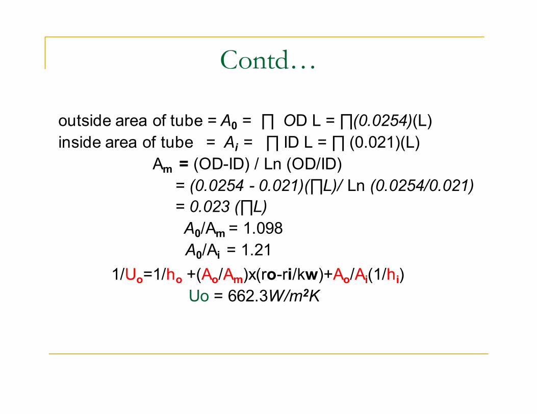
Contd…
outside area of tube = A0 = ∏ OD L = ∏(0.0254)(L)
inside area of tube = Ai = ∏ ID L = ∏ (0.021)(L)
Am = (OD-ID) / Ln (OD/ID)
= (0.0254 - 0.021)(∏L)/ Ln (0.0254/0.021)
= 0.023 (∏L)
A0/Am = 1.098
A0/Ai = 1.21
1/Uo=1/ho +(Ao/Am)x(ro-ri/kw)+Ao/Ai(1/hi)
Uo = 662.3W/m2K

Length of double pipe
Now calculate the required area from
Q = UoAo∆Tm
where,
Q = 1122 kg/h
Uo = 662.3W/m2K
∆Tm= 26.8 C
Ao = Q / Uo∆Tm= 0.74m2
Tube length necessary, L = Ao / ∏ OD1 L
= 0.74 / ∏ (0.0254)
= 9.3 m

Hydraulic design
� In hydraulic design involves calculations of
pressure drop on:
� The pipe side (annulus side)
� The tube side

Contd…
� ∆P = f G2 L / 2 g p Di Φ Where,
� F = friction factor
� G = mass velocity of the fluid
� L = length of the tube
� G =9.8m/s2
� p = density of tube fluid
� Di = inside diameter of tube
� Φ = dimensionless viscosity ratio
� ∆P =pressure drop
� ∆P( tube side ) = 1.476 x 10⁻⁴ kgf/m2
� ∆P( pipe /annulus side ) = 2.50 x 10⁻⁴ kgf/m2

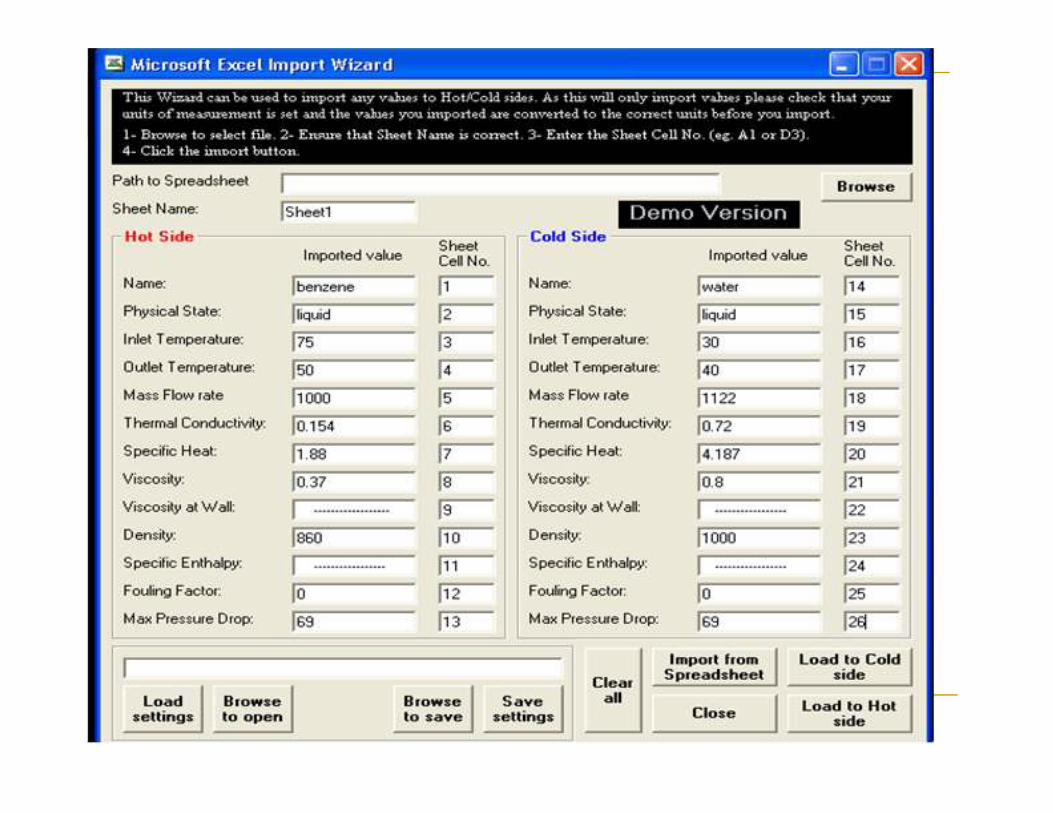
Calculation on software


Auto-cad design (2D & 3D)


DESIGN PROBLEM :
Double Pipe Heat Exchanger
• Double pipe lube oil crude oil exchanger:6900lb/hr of 26 API lube oil must be cooled from 450 to 350F by 72500lb/hr of 34 API mid continent crude oil. The crude oil will be heated from 300 to 310F.
• A fouling factor of 0.003 should be provided for each stream, and the allowable pressure drop on each stream will be 10psi.

CONTINUED…
• A number of 20-ft hairpins of 3 by 2inch IPS are
available. How many must be used, and how shall they
be arranged? The viscosity of crude oil may be obtained
from graph. For the lube oil, viscosities are 1.4cp at
500F, 3.0 at 400F and 7.7 at 300F. These are enough to introduce an error if (u/uw)0.14=1 is assumed.

GIVEN DATA:
• Lube Oil:
• Mass flow
rate=wL=6900lb/hr
• 26 API
• Entering temp.=450F
• Leaving temp.=350F
• Viscosity =3.0cp at 400F
• Crude Oil:
• Mass flow
rate=wc=72500lb/hr
• 34 API
• Entering temp.=300F
• Leaving temp.=310F
• Viscosity = use graph

(1)HEAT DUTY CALCULATION :
� For lube oil: Q=Wcp(T1-T2)
=6900x0.62(450-350) cp(graph) =427000Btu/hr
. For crude oil:
Q=wcp(t2-t1)
=72500x0.585(310-300) cp(graph)
=427000Btu/hr

(2)a LMTD Calculation:
• LMTD = (∆ t)a- (∆ t)b/ln (∆ t)a/ (∆ t)b
(∆ t) = 87.5 F
It will be impossible to put the 72,500lb/hr into single pipe or
annulus, since the flow area of each is too small. Assume
it will be employed in two parallel streams.

(2)bTemperature difference (∆ t):
Hot fluid Temp. Cold fluid Diff.
450 F Higher temp. 310 F 140 F (∆ t)a
350 F Lower temp. 300 F 50 F (∆ t)b
_ _ _ 90 F
(∆ t)a - (∆ t)b

Concept of caloric temperature:
� In our problem we are given with petroleum fractions so we won’t use arithematic temperatures for evaluating physical properties. As in case of petroleum fractions, there viscosities show sharp variations with temperature and also overall heat transfer coefficient doesn’t remain constant. That is why we will use average caloric temperature for evaluating physical properties like viscosity, specific heat etc

(3)Caloric temperatures:
� (∆ t)c/ (∆ t)h =50/140
= 0.357
Kc factor =0.43
caloric temp. fraction (Fc) =0.395 (graph)
� Tc=350x0.395(450-350)=389.5 F
� tc =300x0.395(310-300)=304 F

Basic objective:
� In order to calculate clean overall heat
transfer coefficient Uc , we require two things.
� ho ( from annulus) lube oil
� hio (from inner pipe) crude oil
� Since Uc=hio xho/hio +ho

Concept of outer and inner diameter:
� We will always take inner diameter of inner pipe while
calculating the flow area in tube.
� In case of annulus inner diameter of outer pipe and outer
diameter of inner pipe (equivalent diameter) is considered.. table
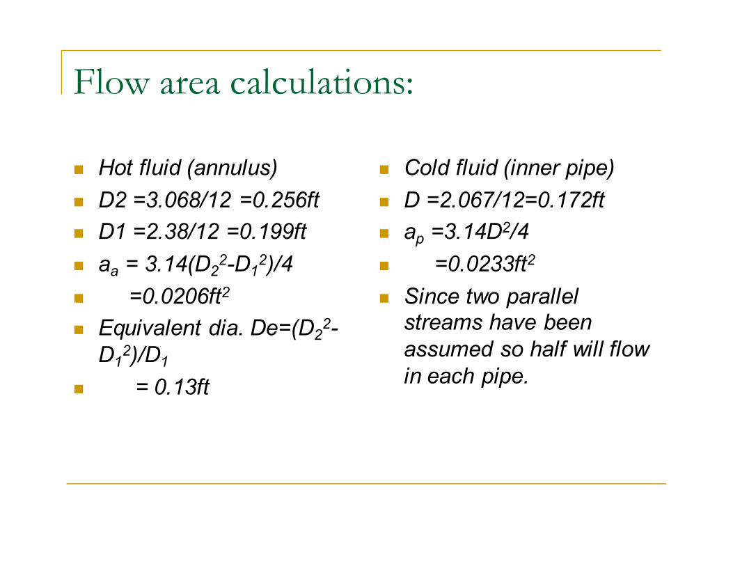
Flow area calculations:
� Hot fluid (annulus)
� D2 =3.068/12 =0.256ft
� D1 =2.38/12 =0.199ft
� aa = 3.14(D22-D1
2)/4
� =0.0206ft2
� Equivalent dia. De=(D22-
D12)/D1
� = 0.13ft
� Cold fluid (inner pipe)
� D =2.067/12=0.172ft
� ap =3.14D2/4
� =0.0233ft2
� Since two parallel streams have been
assumed so half will flow
in each pipe.

Mass velocity calculations:
� Ga=W/aa
� =6900/0.0206
� =335000lb/hrft2
� At Tc=389.5F µ=3.0cp
� =3x2.42=7.25lb/hrft
� Rea=DeGa/µ=0.13x335000/7.25=6000
� If only two hairpins in series are required,L/D will be 2x40/0.13=614
� Use L/D=600
� jH=20.5
� Ga=w/ap
�
=72500/(2x0.0233)=1560000lb/hrft2
� At tc=304F, µ=0.83cp
� Rep=DGp/µ
�
=0.172x1560000/2.01=133500
� jH=320

Calculation of hio and ho :
� Tc=389.50F ,
� C=0.615Btu/lbF (graph)
� K=0.067Btu/hrft2(F/ft)
(graph)
� Pr=(cµ/k)0.33=(0.615x7.2
5/0.067)0.33=4.05
� tc =304F
� c=0.585Btu/lbF (graph)
� K=0.073Btu/hrft2(F/ft)
(graph)
� Pr=(cµ/k)0.33=(0.585x2.0
1/0.073)0.33=2.52

Continued…
� ho= jHxk/De(cµ/k)0.33xΦa
� ho/Φa =20.5x0.067x4.05/0.13 =42.7btu/hrft2F
� tw=tc+ (ho/Φa)/(hio/Φp)+(ho/Φa)x(Tc-tc)
� hi= jHxk/D(cµ/k)0.33xΦp
� hi/Φp =� 320x0.073x2.52/0.172=
34btu/hrft2F� (hio/Φp)=(hio/Φp)x(ID/
OD)
� =342x2.067/2.38=297

Continued….
� tw=304+42.7/(297+42.7)x(
389.5-304)
� =314F
� µw=6.6x2.42=16lb/fthr
� Φa=(µ/µw)0.14=0.9
� ho= ho/Φa xΦe
� =38.4
� As tw is calculated
� µw=0.77x2.42=1.86
� Φp=(µ/µw)0.14=1.0
� ho= hw/Φp xΦw
� =297x1.0=297

Clean overall & design overall co-
efficient….
• Uc=(hioxho)/(hio
ho)=297x38.4/(297+38.4)
=34.0btu/hrft2F
• 1/Ud=1/Uc+Rd
• Rd=0.003x2=0.006hrft2F/Btu
• Ud=28.2
38.4 h (outside) 297
Uc 34 ---
Ud 28.2 ---

Surface area….
� A=Q/(Udx∆t)=173ft2
� External surface per unit ft=0.622ft
� Required length=173/0.622=278lin ft
� This is equivalent to more than six 20-feet hairpins or 240 lin ft. since two parallel streams are employed, use eight hairpins or 320 lin ft. The hairpin should have the annuli connected in series and the tubes in two parallel banks of four exchangers. the corrected Ud will be =24.5.the corrected dirt factor will Rd =1/Ud-1/Uc=0.0114

Pressure drop calculations :
� De = D2 – D1
� = 0.058 ft
� Rea=( De x Ga ) /u
� =2680
� f = 0.0035+0.264/26800.42
� s =0.775 , p=62.5x0.775
= 48.4
� For Rep =133500
� f = 0.0035 +
0.0264/1335000.042
� = 0.005375
� s = 0.076 ,p = 62.5x0.76
=47.5

Continued…
� ∆Fa = 4f Ga2La / 2Gp2De
� =16.07 ft
� V=Ga / 3600 x p
� = 1.9 fps
� ∆ Fl =8(v2 /2G)
� =0.45 ft
� ∆Pa= (16.7 + 0.45) x 48.4 /144
� =5.8 Psi
� Allowable pressure drop =10Psi
� ∆Fp = 4f Ga2La / 2Gp2De
� =25.7 ft
� ∆Pp = 25.7 x47.5/144
� = 8.5 Psi
� Allowable pressure drop =10Psi

Graphical interpretation:
� Pressure drop description:

Designed double pipe heat exchanger:
� Configurated heat exchanger:

Double pipe heat exchange software
calculations:
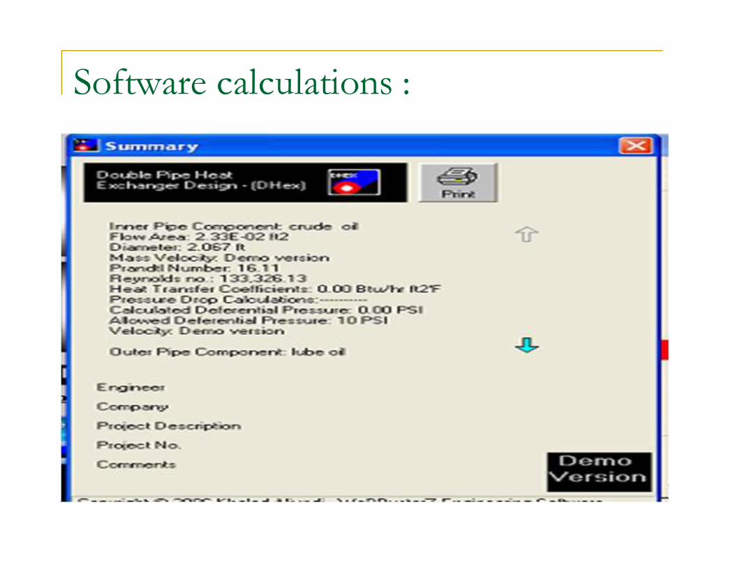
Software calculations :

Continued…
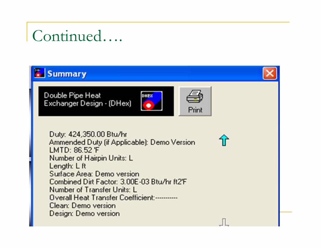
Continued….

Industrial setup flow sheet of double pipe
heat exchanger:
� Process description:
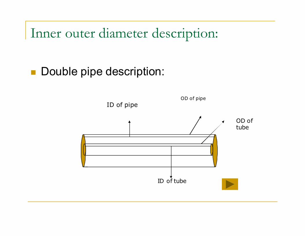
Inner outer diameter description:
OD of pipe
ID of pipe
OD of tube
ID of tube
� Double pipe description:
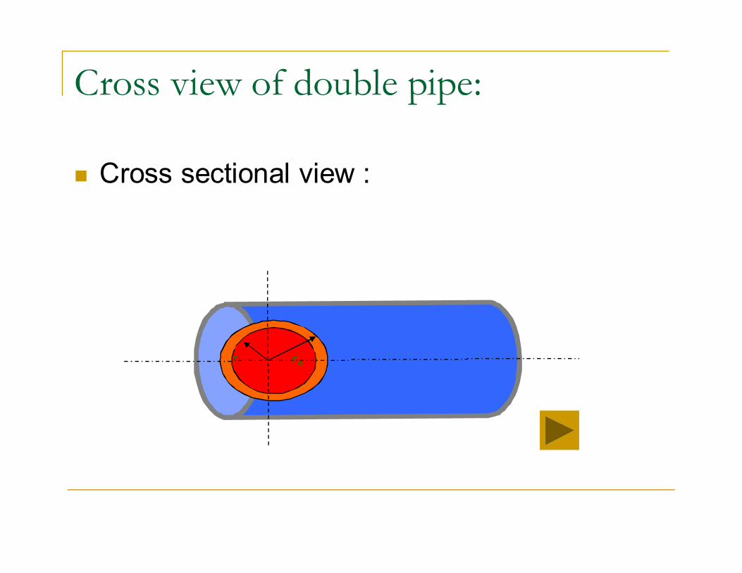
Cross view of double pipe:
� Cross sectional view :
rori

Graphical interpretation:
� Pressure drop description:

Industrial setup flow sheet of double pipe
heat exchanger:
� Process description:

� Donald .Q. Kern (1950) ,heat transfer & applications( 2nd Design problem )
� Binay K.Datta,heat transfer principles and applications( 1st Design problem )
� Max S. Peters, Klaus D.Timmerhaus,Ronald E.West ,plant design and economics for chemical engineers (fifth edition)
� Yunus A.Cengel,Heat & Mass transfer,a practical approach (third edition)
� Y.V.C Rao , heat transfer principles � Incropera,F.P.,Dewitt D.P., Fundamentals of Heat and
Mass Transfer, 5th ed.,John Wiley & Sons Inc., NY,2000� Kakaç S. Heat exchangers selection, rating & thermal
design CRC Press, Fla, 1998
Books references

Internet references
� http://chentserver.uwaterloo.ca/courses/Che025Lab/perry/Chap11.pdf
� http://en.wikipedia.org/wiki/Heat_exchanger#Flow_arrangement� http://www.advantageengineering.com/fyi/110/advantageFYI110
.php� http://www.buildingdesign.co.uk/mech/guntner/dry-air-
coolers.htm� http://www.engineeringpage.com/heat_exchangers/tema.html� http://www.martechsystems.com/downloads/tech_managingreb
oilerops.pdf� http://www.me.wustl.edu/ME/labs/thermal/me372b5.htm� http://www.pacificconsultant.net/compact_heat_exchanger.htm� http://www.rwholland.com/hairpin.htm� http://www.taftan.com/thermodynamics/EXCHANGE.HTM� http://www.thomasnet.com/about/exchangers-heat-shell-tube-
26641001.html


Thermal conductivity from graph:

Specific heat calculation graph:

JH factor calculation using graph:

Caloric temperature graph:

Any question?.