Embed Size (px)
Citation preview
As premium-grade hydrocarbon feed-stocks prices rise, synfuels and novel petrochemical processes are becom-ing increasingly valuable. Natural gas represents an abundant alternative hydrocarbon source to crude oil. It is distributed throughout the world and represents a cleaner fuel compared to crude oil. Therefore, the method of converting natural gas to marketable liquid hydrocarbons (GTL) gets increasing interest worldwide. Large plants have
been erected and are in the design phase with a tremendous need in pro-cess instrumentation including pro-cess analyzer systems.
Siemens, a leader in process analytical instrumentation, has proven over decades its capability to plan, engi-neer, manufacture, implement and service such analyzer systems.
This Case Study provides details about the GTL process and related analyzer tasks.
NG, FT and GTLNatural Gas (NG) is a vital compo-nent of the world's supply of energy. It is one of the cleanest, safest, and most useful of all energy sources.NG is colorless, shapeless, and odor-less in its pure form. It is combusti-ble, and when burned it emits lower levels of potentially harmful by-products into the air than other fuels. NG is a mixture of hydrocar-bon gases. While it is formed prima-rily of methane, it can also include ethane, propane, butane, pentane and certain impurities. NG has been widely used to make commodity products such as methanol or ammonia. But in light of environ-mental and economic climate today it´s conversion to synthetic liquid hydrocarbons has become a most important objective worldwide. It was already in 1923, whenFischer and Tropsch (FT) developed the process of converting coal into „syngas“ and from there into gaso-line. But it took many decades from this FT-process origin before the first commercial FT-based plant, using NG instead of coal, was put into operation. Meanwhile, new technol-ogies have been and are being developed to convert NG to liquids in Gas-to-Liquid (GTL) processes. Commercial interest in using these new technologies arise from e.g. increasing consumer demand for cleaner burning fuels or from the opportunity to develop gas reserves remote from existing markets. Consequently, many GTL plants exist today, are under development or in design phase using different FT-pro-cess technologies (Sasol, Shell, Exxon, e.a.). Whatever technology is applied, the process steps require always to be monitored and con-trolled continuously. Process analyzers play an important role for that. Hundreds of process analyzers, most of them process gas chromatographs, are in use in a typical GTL plant.
Process Analytics in Gas-to-Liquid (GTL) Plants
Ca
se S
tud
y ·
De
cem
be
r 2
00
7
© Siemens AG 2007
2
The GTL process at a glance
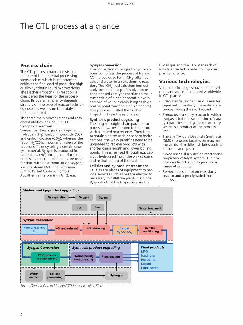
Process chainThe GTL process chain consists of a number of fundamental processing steps each of which is important to achieve the final goal of producing high quality synthetic liquid hydrocarbons. The Fischer-Tropsch (FT) reaction is considered the heart of the process-chain. Its overall efficiency depends strongly on the type of reactor technol-ogy used as well as on the catalyst material applied.
The three main process steps and asso-ciated utilities include (Fig. 1):Syngas generation Syngas (Synthesis gas) is composed of hydrogen (H2), carbon monoxide (CO) and carbon dioxide (CO2), whereas the ration H2/CO is important in view of the process efficiency using a certain cata-lyst material. Syngas is produced from natural gas (NG) through a reforming process. Various technologies are used for that, with or without air or oxygen, such as Steam Methane Reforming (SMR), Partial Oxidation (POX), Autothermal Reforming (ATR), e.a.
Syngas conversionThe conversion of syngas to hydrocar-bons comprises the process of H2 and CO molecules to form -CH2- alkyl radi-cals and water in an exothermic reac-tion. The -CH2- radicals then immedi-ately combine in a preferably iron or cobalt based catalytic reaction to make synthetic olefin and/or paraffin hydro-carbons of various chain-lengths (high boiling point wax and olefinic naphta). This process is called the Fischer-Tropsch (FT) synthesis process.
Synthesis product upgrading The longer straight-chain paraffins are pure solid waxes at room temperature with a limited market only. Therefore, to obtain a better usable scope of hydro-carbons, the waxy paraffins need to be upgraded to recieve products with shorter chain length and lower boiling points. This is realized through e.g. cat-alytic hydrocracking of the wax streams and hydrotreating of the naphta.
Utilities and by-product treatmentUtilities are pieces of equipment to pro-vide services such as heat or electricity necessary to fulfill the plants main goal.By-products of the FT-process are the
FT-tail gas and the FT water each of which is treated in order to improve plant efficiency.
Various technologiesVarious technologies have been devel-oped and are implemented worldwide in GTL plants:
· Sasol has developed various reactor types with the slurry phase distillate process being the most recent.
· Statoil uses a slurry reactor in which syngas is fed to a suspension of cata-lyst particles in a hydrocarbon slurry which is a product of the process itself.
· The Shell Middle Destillate Synthesis (SMDS) process focuses on maximis-ing yields of middle distillates such as kerosene and gas oil.
· Exxon uses a slurry design reactor and propietary catalyst system. The pro-cess can be adjusted to produce a range of products.
· Rentech uses a molten wax slurry reactor and a precipitaded iron catalyst.
Fig. 1: Generic Gas-to-Liquids (GTL) process, simplified
Water treatment
Syngas generation
Syngas Conversion
Utilities and by-product upgrading
Synthesis product upgrading
NG pretreatment Syngasconditioning
NG reforming
Water treatment
HydrogenTail gas processing
Fractionation
Air separation
Final productsLPGNaphthaKerosineDieselLubricants
SyngasH2, CO, CO2
Natural Gas (NG)CH4
Air
Steam
Fuel
Oxygen
FT Synthesis(to synthetic HC)
HydrocrackingHydrotreating
Water treatmentWater treatment
Syngas generation
Syngas Conversion
Utilities and by-product upgrading
Synthesis product upgrading
NG pretreatmentNG pretreatment Syngasconditioning
NG reforming
Water treatment
HydrogenHydrogenTail gas processing
FractionationFractionation
Air separationAir separation
Final productsLPGNaphthaKerosineDieselLubricants
SyngasH2, CO, CO2
Natural Gas (NG)CH4
AirAir
SteamSteam
FuelFuel
OxygenOxygen
FT Synthesis(to synthetic HC)
HydrocrackingHydrotreatingHydrocrackingHydrotreating
© Siemens AG 2007
3
Syngas generation
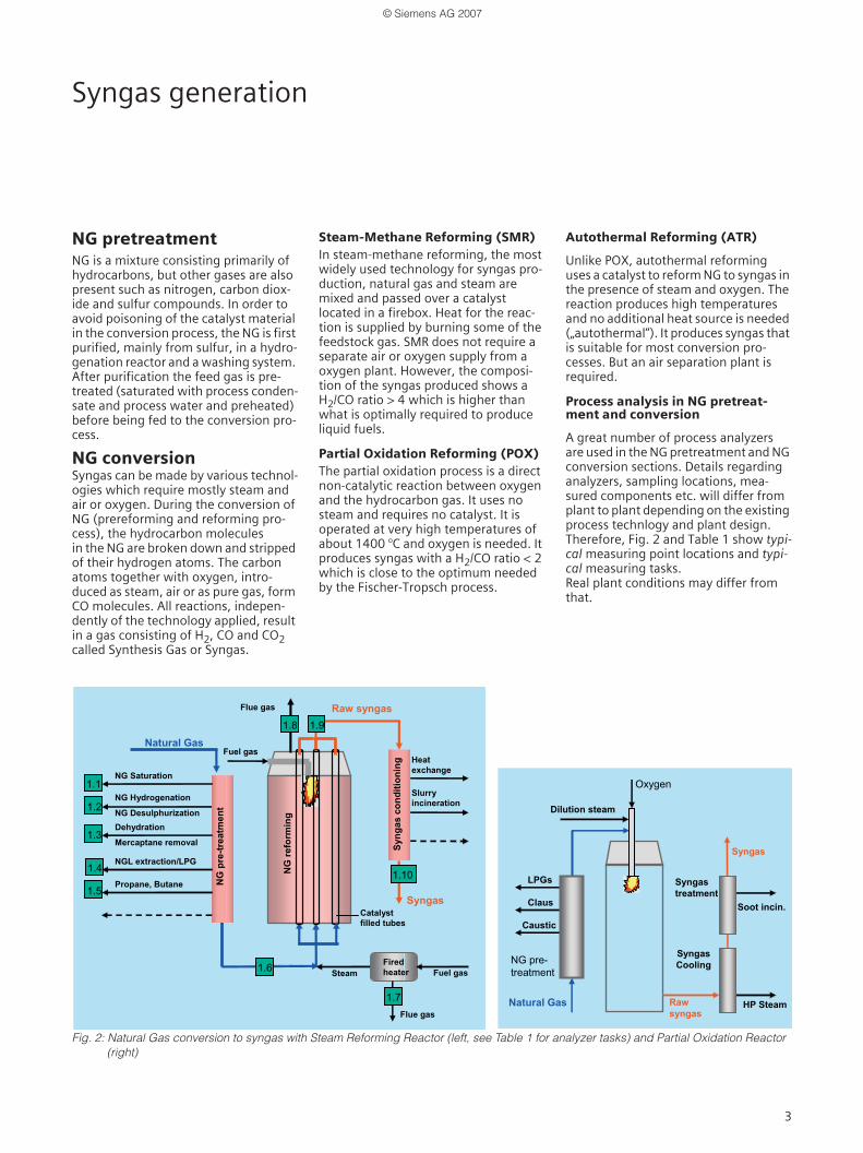
NG pretreatmentNG is a mixture consisting primarily of hydrocarbons, but other gases are also present such as nitrogen, carbon diox-ide and sulfur compounds. In order to avoid poisoning of the catalyst material in the conversion process, the NG is first purified, mainly from sulfur, in a hydro-genation reactor and a washing system. After purification the feed gas is pre-treated (saturated with process conden-sate and process water and preheated) before being fed to the conversion pro-cess.
NG conversion Syngas can be made by various technol-ogies which require mostly steam and air or oxygen. During the conversion of NG (prereforming and reforming pro-cess), the hydrocarbon molecules in the NG are broken down and stripped of their hydrogen atoms. The carbon atoms together with oxygen, intro-duced as steam, air or as pure gas, form CO molecules. All reactions, indepen-dently of the technology applied, result in a gas consisting of H2, CO and CO2 called Synthesis Gas or Syngas.
Steam-Methane Reforming (SMR)In steam-methane reforming, the most widely used technology for syngas pro-duction, natural gas and steam are mixed and passed over a catalyst located in a firebox. Heat for the reac-tion is supplied by burning some of the feedstock gas. SMR does not require a separate air or oxygen supply from a oxygen plant. However, the composi-tion of the syngas produced shows a H2/CO ratio > 4 which is higher than what is optimally required to produce liquid fuels.
Partial Oxidation Reforming (POX)The partial oxidation process is a direct non-catalytic reaction between oxygen and the hydrocarbon gas. It uses no steam and requires no catalyst. It is operated at very high temperatures of about 1400 °C and oxygen is needed. It produces syngas with a H2/CO ratio < 2 which is close to the optimum needed by the Fischer-Tropsch process.
Autothermal Reforming (ATR)
Unlike POX, autothermal reforming uses a catalyst to reform NG to syngas in the presence of steam and oxygen. The reaction produces high temperatures and no additional heat source is needed („autothermal“). It produces syngas that is suitable for most conversion pro-cesses. But an air separation plant is required.
Process analysis in NG pretreat-ment and conversion
A great number of process analyzers are used in the NG pretreatment and NG conversion sections. Details regarding analyzers, sampling locations, mea-sured components etc. will differ from plant to plant depending on the existing process technlogy and plant design. Therefore, Fig. 2 and Table 1 show typi-cal measuring point locations and typi-cal measuring tasks.Real plant conditions may differ from that.
Fig. 2: Natural Gas conversion to syngas with Steam Reforming Reactor (left, see Table 1 for analyzer tasks) and Partial Oxidation Reactor (right)
Fuel gas
Catalyst filled tubes
Steam
Raw syngas
Natural GasHeat exchange
Flue gas
1.8
1.2NG Hydrogenation
NG Desulphurization
NG Saturation
Dehydration
Mercaptane removal
NGL extraction/LPG
NG
pre
-trea
tmen
t
1.3
1.4
Syng
asco
nditi
onin
g
Slurry incineration
Syngas
1.6
NG
refo
rmin
g
Firedheater
Flue gas
1.10
1.7
1.1
1.9
Fuel gas
Propane, Butane1.5
Fuel gas
Catalyst filled tubes
Steam
Raw syngas
Natural GasHeat exchange
Flue gas
1.81.8
1.21.2NG Hydrogenation
NG Desulphurization
NG Saturation
Dehydration
Mercaptane removal
NGL extraction/LPG
NG
pre
-trea
tmen
t
1.31.3
1.41.4
Syng
asco
nditi
onin
g
Slurry incineration
Syngas
1.61.6
NG
refo
rmin
g
Firedheater
Flue gas
1.101.10
1.71.7
1.11.1
1.91.9
Fuel gas
Propane, Butane1.51.5
Oxygen
Dilution steam
HP SteamRawsyngas
NG pre-treatment
Natural Gas
SyngasCooling
LPGs Syngas treatment
Syngas
Soot incin.Claus
Caustic
Oxygen
Dilution steam
HP SteamRawsyngas
NG pre-treatment
Natural Gas
SyngasCooling
LPGs Syngas treatment
Syngas
Soot incin.Claus
Caustic
© Siemens AG 2007
4
Syngas generation (ctd.)Syngas conversion (FT Synthesis)
FT Synthesis In the FT Synthesis, synthesis gas is con-verted into liquid hydrocarbon chains based on the famous „FT Chemistry“. In the chain growth reaction a wide scope of products is formed ranging from very light to heavy paraffins. The most important element of this reaction is the type of catalyst used. Two predominant formulations are in use, one based on iron and the other on cobalt. Both feature advantages and dis-advantages and differ, amongst others, in their suitability with respect to feed composition and desired product scope.
Besides the catalyst, the design and operation principle of the conversion reactor is another key element. Various types of FT reactor systems are in use, which have in common the need to remove the exothermic heat of the reaction. But they show also fundamen-tal differences.
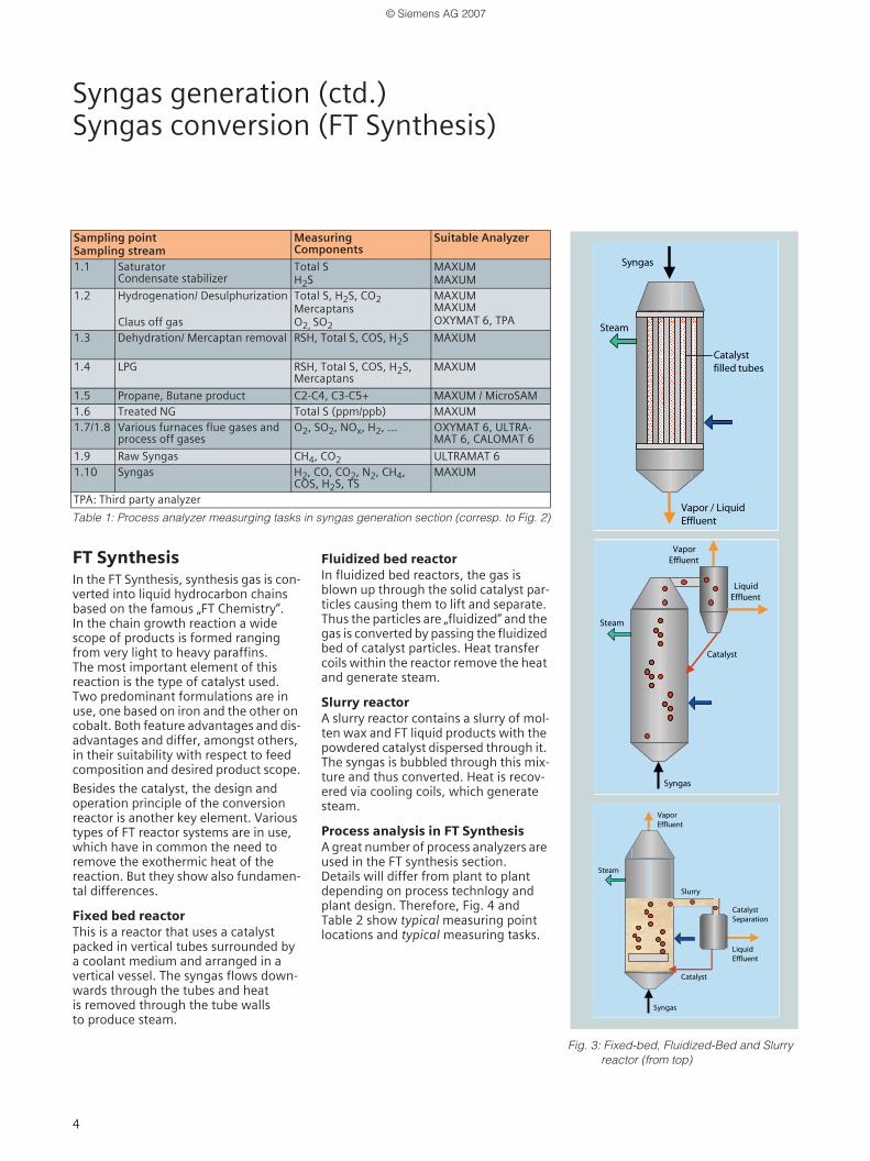
Fixed bed reactor This is a reactor that uses a catalyst packed in vertical tubes surrounded by a coolant medium and arranged in a vertical vessel. The syngas flows down-wards through the tubes and heat is removed through the tube walls to produce steam.
Fluidized bed reactorIn fluidized bed reactors, the gas is blown up through the solid catalyst par-ticles causing them to lift and separate. Thus the particles are „fluidized“ and the gas is converted by passing the fluidized bed of catalyst particles. Heat transfer coils within the reactor remove the heat and generate steam.
Slurry reactorA slurry reactor contains a slurry of mol-ten wax and FT liquid products with the powdered catalyst dispersed through it. The syngas is bubbled through this mix-ture and thus converted. Heat is recov-ered via cooling coils, which generate steam.
Process analysis in FT SynthesisA great number of process analyzers are used in the FT synthesis section. Details will differ from plant to plant depending on process technlogy and plant design. Therefore, Fig. 4 and Table 2 show typical measuring point locations and typical measuring tasks.
Syngas
Catalyst filled tubes
Steam
Vapor / Liquid Effluent
Syngas
Catalyst filled tubes
Steam
Vapor / Liquid Effluent
Syngas
Steam
Vapor Effluent
Liquid Effluent
Catalyst
Syngas
Steam
Vapor Effluent
Liquid Effluent
Catalyst
Syngas
Steam
Vapor Effluent
Liquid Effluent
CatalystSeparation
Catalyst
Slurry
Syngas
Steam
Vapor Effluent
Liquid Effluent
CatalystSeparation
Catalyst
Slurry
Table 1: Process analyzer measurging tasks in syngas generation section (corresp. to Fig. 2)
Sampling point Sampling stream
MeasuringComponents
Suitable Analyzer
1.1 SaturatorCondensate stabilizer
Total SH2S
MAXUMMAXUM
1.2 Hydrogenation/ Desulphurization
Claus off gas
Total S, H2S, CO2MercaptansO2, SO2
MAXUMMAXUMOXYMAT 6, TPA
1.3 Dehydration/ Mercaptan removal RSH, Total S, COS, H2S MAXUM
1.4 LPG RSH, Total S, COS, H2S, Mercaptans
MAXUM
1.5 Propane, Butane product C2-C4, C3-C5+ MAXUM / MicroSAM1.6 Treated NG Total S (ppm/ppb) MAXUM1.7/1.8 Various furnaces flue gases and
process off gasesO2, SO2, NOx, H2, ... OXYMAT 6, ULTRA-
MAT 6, CALOMAT 6
1.9 Raw Syngas CH4, CO2 ULTRAMAT 61.10 Syngas H2, CO, CO2, N2, CH4,
COS, H2S, TSMAXUM
TPA: Third party analyzer
Fig. 3: Fixed-bed, Fluidized-Bed and Slurry reactor (from top)
© Siemens AG 2007

5
Product Upgrade and By-product Treatment
Product UpgradeConventional refinery processes can be used for upgrading of FT liquid and wax products such as fractionation,hydroc-racking, isomerization, hydrotreating etc. (Fig. 4). Final products from FT synthesis are of high quality due to a very low aromatics and almost zero sulfur content.
Primary separationPrimary separation occurs already within the FT block (Fig. 4) and basically separates from each other
· the straight-run synthetic hydrocarbon FT liquid streams.
· the non-converted FT tail gas,
· the FT water streams,
· the molten wax stream
Hydrocracking/Isomerization (HCI)Hydrocracking is preferably used to con-vert the wax into lighter distillates with shorter chain length and lower boiling points. It uses fixed-bed reactors and suitable catalysts. Hydrogen is supplied either with PSA purity or as pure hydro-gen made from a slip stream of syngas.
HydrogenationHydrogenation is applied to the naphta to saturate straight-run product streams.
FractionationLiquid effluent from the hydrocrack-ing/isomerizaton block is heated and then distilled. The separate products are withdrawn, cooled and sent to their storage tanks.
By-product treatment
FT Tail Gas FT tail gas represents unconverted reactants and light hydrocarbons which are normally recycled to the syngas generation section. However, this is possi-ble only to a certain limit due to the pres-ence and build-up of gases such as Nitrogen and Argon. Therefore, the tailgas is partly purged out of the sys-tem and possibly used for combustion e.g. in a gas turbine. In the extreme case no recy-cle is possible and all tail gas is purged.
The tail gas contains components such as hydrogen, water, methane, carbon monoxide, carbon dioxide, nitrogen argon, and heavier hydrocarbons.
Typically hydrogen is removed from the tail gas for further use by a PSA (Pres-sure Swing Absorber).
FT Synthetic WaterFT synthetic water is co-produced and need to be removed from the reactor. Some of the contained components can be recycled to the syngas generation section, while other must be removed
by a special water treatment procedure (stripping by steam, removing by mechanical means, converting through biological measures).
Process analysis in product upgrade and by-product treatmentA great number of process analyzers are used in the product upgrade and by-product treatment section. Details will differ from plant to plant depending on process technlogy and plant design.
Fig. 4 and Table 2 show typical measur-ing point locations and typical measur-ing tasks.
Table 2: Process analyzer measuring tasks in the FT synthesis and product upgrade section
Sampling point Sampling stream
Measuring Component Suitable Analyzer
3.1 Syngas feed H2, CO, CO2, N2, CH4, COS, H2S,Total S
MAXUM
3.2 Syngas FT reactor H2S, COS, Total S MAXUM
3.2 Syngas FT reactor H2, CO, CH4, N2, C2-C6+,H2/CO ratio MAXUM / MicroSAM
3.3 Tail gas, PSA unit CO; CO/CO2 ULTRAMAT 6 / MicroSAM
3.4 Recycle gas CO, CO2, CH4, N2,H2, H2/CO ratio MAXUM
3.5 Off gas H2, CO, CH4, N2, C2-C5, H2/CO ratio MAXUM
3.6 FT liquids Related components MAXUM
3.7 LPG C4, C5+ MAXUM / MicroSAM
3.8 Final products Related components MAXUM
Various off/flue gases O2 OXYMAT 6/61
Various off/flue gases SO2, NOx ULTRAMAT 6
Fig. 4: FT Synthesis and Upgrade of FT products
Recycle Off Gas
FT Water Wax
FT Liquids
FT Tail Gas
Hydrocracking
FT ReactorSyngas
Fractionation
Hydrogenation
Recycle
Lubricants
Naphtha
LPG
Kerosene
Diesel3.1
3.2
3.3
3.4 3.53.7
3.8
3.8
3.8
3.6
Recycle Off Gas
FT Water Wax
FT Liquids
FT Tail Gas
Hydrocracking
FT ReactorSyngas
Fractionation
Hydrogenation
Recycle
Lubricants
Naphtha
LPG
Kerosene
Diesel3.13.1
3.23.2
3.33.3
3.43.4 3.53.53.73.7
3.83.8
3.83.8
3.83.8
3.63.6
© Siemens AG 2007
6
Utilities
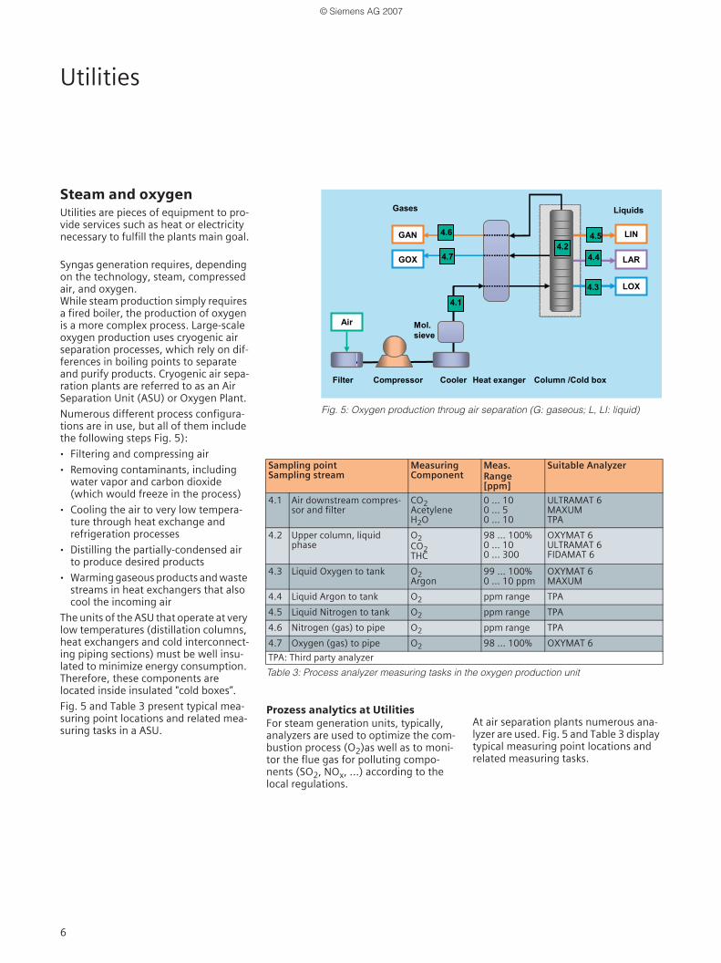
Steam and oxygenUtilities are pieces of equipment to pro-vide services such as heat or electricity necessary to fulfill the plants main goal.
Syngas generation requires, depending on the technology, steam, compressed air, and oxygen. While steam production simply requires a fired boiler, the production of oxygen is a more complex process. Large-scale oxygen production uses cryogenic air separation processes, which rely on dif-ferences in boiling points to separate and purify products. Cryogenic air sepa-ration plants are referred to as an Air Separation Unit (ASU) or Oxygen Plant.
Numerous different process configura-tions are in use, but all of them include the following steps Fig. 5):
· Filtering and compressing air
· Removing contaminants, including water vapor and carbon dioxide (which would freeze in the process)
· Cooling the air to very low tempera-ture through heat exchange and refrigeration processes
· Distilling the partially-condensed air to produce desired products
· Warming gaseous products and waste streams in heat exchangers that also cool the incoming air
The units of the ASU that operate at very low temperatures (distillation columns, heat exchangers and cold interconnect-ing piping sections) must be well insu-lated to minimize energy consumption. Therefore, these components are located inside insulated "cold boxes”.
Fig. 5 and Table 3 present typical mea-suring point locations and related mea-suring tasks in a ASU.
Prozess analytics at UtilitiesFor steam generation units, typically, analyzers are used to optimize the com-bustion process (O2)as well as to moni-tor the flue gas for polluting compo-nents (SO2, NOx, ...) according to the local regulations.
At air separation plants numerous ana-lyzer are used. Fig. 5 and Table 3 display typical measuring point locations and related measuring tasks.
Fig. 5: Oxygen production throug air separation (G: gaseous; L, LI: liquid)
Cooler CompressorFilter
Mol. sieve
Column /Cold box
LOX
Air
Heat exanger
LIN
LAR
GAN
GOX
LiquidsGases
4.1
4.6 4.5
4.4
4.3
4.24.7
Cooler CompressorFilter
Mol. sieve
Column /Cold box
LOX
Air
Heat exanger
LIN
LAR
GAN
GOX
LiquidsGases
4.1
4.64.6 4.5
4.4
4.3
4.24.7
Table 3: Process analyzer measuring tasks in the oxygen production unit
Sampling point Sampling stream
MeasuringComponent
Meas. Range[ppm]
Suitable Analyzer
4.1 Air downstream compres-sor and filter
CO2AcetyleneH2O
0 ... 100 ... 50 ... 10
ULTRAMAT 6MAXUMTPA
4.2 Upper column, liquid phase
O2CO2THC
98 ... 100%0 ... 100 ... 300
OXYMAT 6ULTRAMAT 6FIDAMAT 6
4.3 Liquid Oxygen to tank O2Argon
99 ... 100%0 ... 10 ppm
OXYMAT 6MAXUM
4.4 Liquid Argon to tank O2 ppm range TPA
4.5 Liquid Nitrogen to tank O2 ppm range TPA
4.6 Nitrogen (gas) to pipe O2 ppm range TPA
4.7 Oxygen (gas) to pipe O2 98 ... 100% OXYMAT 6
TPA: Third party analyzer
© Siemens AG 2007
7
Siemens Process Analytics at a glanceProducts
Siemens Process AnalyticsSiemens Process Analytics is a leading provider of process analyzers and pro-cess analysis systems. We offer our glo-bal customers the best solutions for their applications based on innovative analysis technologies, customized sys-tem engineering, sound knowledge of customer applications and professional support. And with Totally Integrated Automation (TIA). Siemens Process Analytics is your qualified partner for efficient solutions that integrate pro-cess analysers into automations sys-tems in the process industry.
From demanding analysis tasks in the chemical, oil & gas and petrochemical industry to combustion control in power plants to emission monitoring at waste incineration plants, the highly accurate and reliable Siemens gas chro-matographs and continuous analysers will always do the job.
Siemens process Analytics offers a wide and innovative portfolio designed to meet all user requirements for compre-hensive products and solutions.
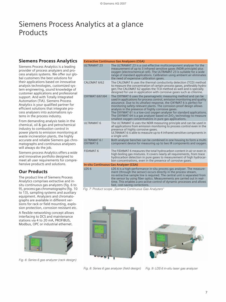
Our ProductsThe product line of Siemens Process Analytics comprises extractive and in-situ continuous gas analyzers (fig. 6 to 9), process gas chromatographs (fig. 10 to 13), sampling systems and auxiliary equipment. Analyzers and chromato-graphs are available in different ver-sions for rack or field mounting, explo-sion protection, corrosion resistant etc.
A flexible networking concept allows interfacing to DCS and maintenance stations via 4 to 20 mA, PROFIBUS,Modbus, OPC or industrial ethernet.
Fig. 6: Series 6 gas analyzer (rack design)
Fig. 7: Product scope „Siemens Continuous Gas Analyzers“
Extractive Continuous Gas Analyzers (CGA)ULTRAMAT 23 The ULTRAMAT 23 is a cost-effective multicomponent analyser for the
measurement of up to 3 infrared sensitive gases (NDIR principle) plusoxygen (electrochemical cell). The ULTRAMAT 23 is suitable for a wide range of standard applications. Calibration using ambient air eliminates the need of expensive calibration gases.
CALOMAT 6/62 The CALOMAT 6 uses the thermal conductivity detection (TCD) method to measure the concentration of certain process gases, preferably hydro-gen.The CALOMAT 62 applies the TCD method as well and is speciallydesigned for use in application with corrosive gases such as chlorine.
OXYMAT 6/61/64 The OXYMAT 6 uses the paramagnetic measuring method and can be used in applications for process control, emission monitoring and quality assurance. Due to its ultrafast response, the OXYMAT 6 is perfect for monitoring safety-relevant plants. The corrosion-proof design allows analysis in the presence of highly corrosive gases.The OXYMAT 61 is a low-cost oxygen analyser for standard applications.The OXYMAT 64 is a gas analyzer based on ZrO2 technology to measure smallest oxygen concentrations in pure gas applications.
ULTRAMAT 6 The ULTRAMAT 6 uses the NDIR measuring principle and can be used in all applications from emission monitoring to process control even in the presence of highly corrosive gases.ULTRAMAT 6 is able to measure up to 4 infrared sensitive components in a single unit.
ULTRAMAT 6 /OXYMAT 6
Both analyzer benches can be combined in one housing to form a multi-component device for measuring up to two IR components and oxygen.
FIDAMAT 6 The FIDAMAT 6 measures the total hydrocarbon content in air or even in high-boiling gas mixtures. It covers nearly all requirements, from trace hydrocarbon detection in pure gases to measurement of high hydrocar-bon concentrations, even in the presence of corrosive gases.
In-situ Continuous Gas Analyzer (CGA)LDS 6 LDS 6 is a high-performance in-situ process gas analyser. The measure-
ment (through the sensor) occurs directly in the process stream,no extractive sample line is required. The central unit is separated from the sensor by using fiber optics. Measurements are carried out in real-time. This enables a pro-active control of dynamic processes and allows fast, cost-saving corrections.
Fig. 8: Series 6 gas analyzer (field design) Fig. 9: LDS 6 in-situ laser gas analyzer
© Siemens AG 2007

8
Siemens Process Analytics at a glanceProducts (continued) and Solutions
Fig. 10: MAXUM edition II Process GC
Fig. 11: MicroSAM Process GC
Fig. 12: SITRANS CV Natural Gas Analyzer
Our solutionsAnalytical solutions are always driven by the customer´s requirements. We offer an integrated design covering all steps from sampling point and sample preparation up to complete analyser cabinets or for installation in analyser shelters (fig. 14). This includes also sig-nal processing and communications to the control room and process control system.
We rely on many years of world-wide experience in process automation and engineering and a collection of special-ized knowledge in key industries and industrial sectors. We provide Siemens quality from a single source with a func-tion warranty for the entire system.
Read more in "Our Services“.
Fig. 14: Analyzer house (shelter)
Process Gas Chromatographs (Process GC) MAXUM edition II MAXUM edition II is very well suited to be used in rough industrial envi-
ronments and performs a wide range of duties in the chemical and pet-rochemical industries and refineries.MAXUM II features e. g. a flexible, energy saving single or dual oven con-cept, valveless sampling and column switching, and parallel chromatog-raphy using multiple single trains as well as a wide range of detectors such as TCD, FID, FPD, PDHID, PDECD and PDPID.
MicroSAM MicroSAM is a very compact explosion-proof micro process chromato-graph. Using silicon-based micromechanical components it combines miniaturization with increased performance at the same time.MicroSAM is easy to use and its rugged and small design allows mount-ing right at the sampling point. MicroSAM features drastically reduced cycle times, provides valveless sample injection and column switching and saves installation, maintenance, and service costs.
SITRANS CV SITRANS CV is a micro process gas chromatograph especially designed for reliable, exact and fast analysis of natural gas. The rugged and com-pact design makes SITRANS CV suitable for extreme areas of use, e.g. off-shore exploration or direct mounting on a pipeline.The special software "CV Control" meets the requirements of the natural gas market, e.g. custody transfer.
Fig. 13: Product scope „Siemens Process Gas Chromatographs“
© Siemens AG 2007
9
Siemens Process Analytics at a glanceSolutions (continued) and Services
Our solutions ...
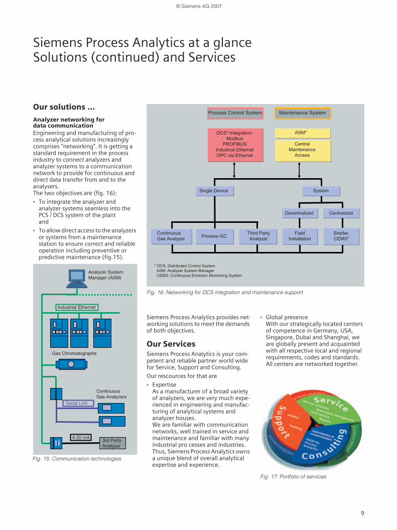
Analyzer networking fordata communication Engineering and manufacturing of pro-cess analytical solutions increasingly comprises "networking". It is getting a standard requirement in the process industry to connect analyzers andanalyzer systems to a communication network to provide for continuous and direct data transfer from and to the analysers.The two objectives are (fig. 16):
· To integrate the analyzer andanalyzer systems seamless into the PCS / DCS system of the plantand
· To allow direct access to the analyzers or systems from a maintenancestation to ensure correct and reliable operation including preventive orpredictive maintenance (fig.15).
Siemens Process Analytics provides net-working solutions to meet the demands of both objectives.
Our ServicesSiemens Process Analytics is your com-petent and reliable partner world wide for Service, Support and Consulting.
Our rescources for that are
· ExpertiseAs a manufacturer of a broad variety of analyzers, we are very much expe-rienced in engineering and manufac-turing of analytical systems and analyzer houses.We are familiar with communication networks, well trained in service and maintenance and familiar with many industrial pro cesses and industries.Thus, Siemens Process Analytics owns a unique blend of overall analytical expertise and experience.
· Global presenceWith our strategically located centers of competence in Germany, USA,Singapore, Dubai and Shanghai, we are globally present and acquainted with all respective local and regional requirements, codes and standards.All centers are networked together.
Fig. 16: Networking for DCS integration and maintenance support
Fig. 17: Portfolio of services
Fig. 15: Communication technologies
© Siemens AG 2007
10
Siemens Process Analytics at a glanceServices, continued
Our Services ...
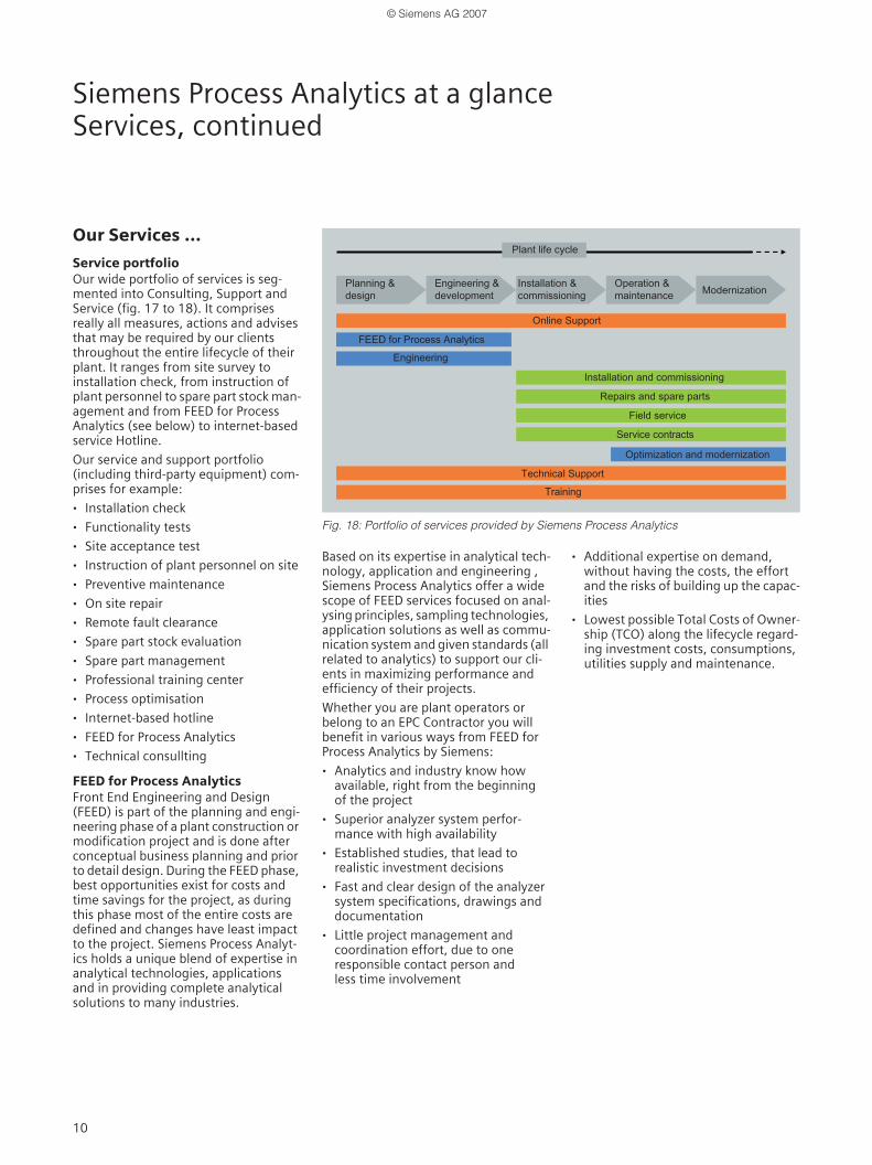
Service portfolio Our wide portfolio of services is seg-mented into Consulting, Support and Service (fig. 17 to 18). It comprises really all measures, actions and advises that may be required by our clients throughout the entire lifecycle of their plant. It ranges from site survey to installation check, from instruction of plant personnel to spare part stock man-agement and from FEED for Process Analytics (see below) to internet-based service Hotline.
Our service and support portfolio (including third-party equipment) com-prises for example:
· Installation check
· Functionality tests
· Site acceptance test
· Instruction of plant personnel on site
· Preventive maintenance
· On site repair
· Remote fault clearance
· Spare part stock evaluation
· Spare part management
· Professional training center
· Process optimisation
· Internet-based hotline
· FEED for Process Analytics
· Technical consullting
FEED for Process AnalyticsFront End Engineering and Design (FEED) is part of the planning and engi-neering phase of a plant construction or modification project and is done after conceptual business planning and prior to detail design. During the FEED phase, best opportunities exist for costs and time savings for the project, as during this phase most of the entire costs are defined and changes have least impact to the project. Siemens Process Analyt-ics holds a unique blend of expertise in analytical technologies, applications and in providing complete analytical solutions to many industries.
Based on its expertise in analytical tech-nology, application and engineering , Siemens Process Analytics offer a wide scope of FEED services focused on anal-ysing principles, sampling technologies, application solutions as well as commu-nication system and given standards (all related to analytics) to support our cli-ents in maximizing performance and efficiency of their projects.
Whether you are plant operators or belong to an EPC Contractor you will benefit in various ways from FEED for Process Analytics by Siemens:
· Analytics and industry know how available, right from the beginning of the project
· Superior analyzer system perfor-mance with high availability
· Established studies, that lead to realistic investment decisions
· Fast and clear design of the analyzer system specifications, drawings and documentation
· Little project management and coordination effort, due to one responsible contact person and less time involvement
· Additional expertise on demand, without having the costs, the effort and the risks of building up the capac-ities
· Lowest possible Total Costs of Owner-ship (TCO) along the lifecycle regard-ing investment costs, consumptions, utilities supply and maintenance.
Fig. 18: Portfolio of services provided by Siemens Process Analytics
© Siemens AG 2007
www.siemens.com/processanalytics © Siemens AG 2007Subject to change
Case Study
Siemens AGAutomation and DrivesSensors and CommunicationProcess Analytics76181 KARLSRUHEGERMANY
Siemens Process Analytics - Answers for industry
If you have any questions, please contact your local sales representative or any of the contact addresses below:
Siemens AGA&D SC PA, Process AnalyticsÖstliche Rheinbrückenstr. 5076187 KarlsruheGermany
Phone: +49 721 595 3829Fax: +49 721 595 6375E-mail:[email protected]/prozessanalytics
Siemens Ltd., ChinaA&D SC, Process Analytics7F, China Marine TowerNo.1 Pu Dong AvenueShanghai, 200120P.R.China
Phone: +86 21 3889 3602Fax: +86 21 3889 3264E-mail: [email protected]
Siemens Energy & Automation Inc.7101 Hollister RoadHouston, TX 77040USA
Phone: +1 713 939 7400Fax: +1 713 939 9050E-mail: [email protected]
www.siemens.com/processanalytics
Siemens LLCA&D 2B.PO Box 2154,Dubai, U.A.E.
Phone: +971 4 366 0159Fax: +971 4 3660019E-mail: [email protected]/processanalytics
Siemens Pte. LimitedA&D SC PS/PA CoC60 MacPherson RoadSingapore 348615
Phone: +65 6490 8728Fax: +65 6490 8729E-mail: [email protected]
www.siemens.com/processanalytics
© Siemens AG 2007