Embed Size (px)
Citation preview
Miscellaneous Paper GL-93 1.9
AD-A270 529 August 1993
US Army Corpsof EngineersWaterways ExperimentStation
Proceedings, Workshop on Predictionof Groundwater Flow into DeepTunnels and Excavations
18-19 February 1987
by Richard E. Goodman, Anders Bro, editorsGeotechnical Laboratory
OTIC
Approved For Public Release; Distribution Is Unlimited
j8 I: 93-23168
Prepared for Headquarters, U.S. Army Corps of Engineers
The contents of this report are not to be used for advertising,publication, or promotional purposes. Citation of trade namesdoes not constitute an official andorsement or approval of the useof such commercial products.
Ira PRW ON RECYCLED PAPER
Miscellaneous Paper GL-93-19August 1993
Proceedings, Workshop on Predictionof Groundwater Flow into DeepTunnels and Excavations
18-19 February 1987
by Richard E. Goodman, Anders Bro, editors
Geotechnical Laboratory
U.S. Army Corps of EngineersWaterways Experiment Station3909 Halls Ferry RoadVicksburg, MS 39180-6199
"Accesion ForNTIS CRA&I ---
DTIC TABUnannoiiccdJL'.stfilcation
By
Final report ,Approved for public release; distribution is unlimited ____
Prepared for U 4. ry Corps of EngineersWashington, DC 20314-1000
US Army Corpsof EngineersWaterways Experiment /N
Stationep St i a
Proceding, Workso onPeicinoGonwte lwinDe
"--IBUtECICA I
49l p.:iI.;28c.- (isellneuspaer;GL9319
"IncludesE bibliogaphica refernces
I.ClY GA U, rS ArM y.iNIERWATE"RIWAVIOMISHltINTl P•ATONl
PHONElI: (U"Ww"lI
Waterways Experiment Station Cataloging-In-Publication Data
Proceedings, Workshop on Prediction of Groundwater Flow into DeepTunnels and Excavations( 18-19 February 1987 / by Richard E. Good-man, Anders Bro, editors; prepared U.S. Army Corps of Engineers.
49 p.: ill.; 28 cm. -- (Miscellaneous paper; GL-93-19)Includes bibliographical references.1. Groundwater flow -- Congresses. 2. Tunnels -- Congresses.
3. Shafts (Excavations) -- Congresses. 4. Seepage -- Congresses.1. Goodman, Richard E. 11. Bro, Anders. Ill. United States. Army.Corps of Engineers. IV. U.S. Arrmy Engineer Waterways ExperimentStation. V. Workshop on Prediction of Groundwater Flow irt'.ý Deep Tun-nels and Excavations (1987: Vicksburg, Mississippi) V. Series: Miscel-laneous paper (U.S. Army Engineer Waterways Experiment Station);GL-93-19.TA7 W34m no.GL-93-19
CONTENTS
Acknowledgements .................. ............................ .... iv
Preface .................... ................................... v
1-Purpose of the Conference .............. ...................... 1
2-Summary of Presentations and Noteworthy Comments ...... ........... 3
3-Review of Submitted Papers ............ ...................... .... 13
4-Further Discussion and General Comments ..... ............... ... 25
References .................... ............................... .... 27
Appendix A: List of Attendees ................ ..................... Al
Appendix B: Papers and Reports ................. .................... BI
iii
ACKNOWLEDGEMENTS
This conference is dedicated to Mr. Paul Fisher who was the driving forcebehind investigating the problems due to groundwater in deep bases. U.S. ArmyEngineer Waterways Experiment Station, in particular Dr. Don C. Banks and Mr.Jerry S. Huie, are thanked for initiating and supporting the conference.
We greatly appreciate the generosity of the participants who devotedpersonal time and resources to participate in the conference. The participantscontributed their knowledge, understanding, and experience in the field of waterflow in underground works. Thanks are also due to Mr. Rick Sisson for logisticalplanning and recording the conference.
We would also like to acknowledge the funding agencies who made thisconference possible: the U. S. Army Corps of Engineers, The Defense NuclearAgency, and the U. S. Air Force Ballistic Missile Office.
iv
PREFACE
The workshop proceedings reported herein were conducted for the U.S.Army Engineer Waterways Experiment Station (WES).
The Principal Investigator was Dr. Wendell 0. Miller, Rock Mechanics Branch(RMB), Soil and Rock Mechanics Division (S&RMD), Geotechnical Laboratory (GL),WES. The workshop proceedings were written by Dr. Anders Bro and Dr. Richard E.Goodman, University of California at Berkeley.
Supervision at WES was provided by Mr. J. S. Huie, Chief, RMB. The projectwas conducted under the general supervision of Dr. D. C. Banks, Chief, S&RMD; andDr. W. F. Marcuson III, Director, GL.
At the time of publication of this report, Director of WES wasDr. Robert W. Whalin. Commander was COL Bruce K. Howard, EN.
v
1 Purpose of the Conference
At the time of the conference, a deep underground base was a viable alternative forbasing strategic defense systems. Among many of the questions that needed to be con-sidered in establishing the suitability of such a basing system was how water would im-pact the survivability of the base. A hypothetical geology was proposed (Generic Moun-tain "C") which was analyzed by a number of private companies and individuals. A con-sensus was generally reached that the model contained inconsistencies, thus leading toseveral revisions. Although analyses of water flow were done, there seemed to be littleconfidence in their estimates and it became evident to practical tunnelers that a closer lookat predictive techniques was required.
This conference was therefore convened to draw together a group of authoritative peo-ple in the field of flow modelling to establish and document the problems encountered withwater in tunnelling and the difficulties in modelling underground flow, and to discuss thegamut of predictive techniques. The results of this conference are discussed in theseproceedings. In short, experience indicates that encounters with significant water inflowsare unpredictable. Most modelling efforts have been performed using homogeneous mod-els; this cannot result in reliable predictions of flows in any given short section of tunnel.Some current efforts directed toward modelling flow probabilistically seem promising.Most of the case studies and field experiences focused on the transient flows that areencountered during initial excavation. Although these flows are certainly important withregard to the economy of construction, they may not be relevant to long-term seepage intoan underground base, which would be of greater concern to the deep basing commun'ty.Despite this slight shift in focus, the material presented at the conference was revealingand suggests some directions of research that could be productively pursued.
In summary:
a. The focus of this report is on the analysis and prediction of water flow into deepunderground excavations in rock. It does not address remedial measures that couldbe taken to stem water inflows.
b. Geologic uncertainties and variability inherent in fracture characteristics (the frac-ture locations, apertures, extents, etc.) lend little confidence to flow predictions.
c. Where these uncertainties can be reduced, numerical techniques can be used topredict flows as a function of time.
d. In light of these inherent uncertainties, statistical and probabilistic techniques arebeing developed to assess geological data, to statistically model flow, and to quan-tify the confidence of flow calculations.
e. Further work is needed to refine current analytical techniques used for interpretingbasic hydrologic data (field test data).
f. Statistical simulaticn methods look promising and should be continued, perhapswith a goal of predicting actual flows and the probability of encountering suchflows, in addition to the current goal of studying the ilow behavior of fracture sys-tems.
g. The phenomenon of flow channeling needs to be addressed. The impact that chan-nelling has on the flow magnitudes, the localization of flow, and the variability thatchanneling introduces needs to be investigated.
2
2 Summary of Presentations and Note-worthy Comments Made During thePresentations
This section highlights the most important aspects of the presentations and commentsmade by the attendees during the presentations. These comments are gleaned from thetape recordings and notes taken during the conference.
Day 1
Richard E. Goodman
Professor Goodman set the stage for the conference by introducing the problems thathave been encountered due to water flowing into underground excavations. He proceededto suggest the conditions under which one is apt to find water, and proceeded to presentthe analyses that he and others had done in the 1960s. The analyses are covered in hispaper1 (included in Appendix A).
His experiences, as expounded upon in his presentation, were that the ability of engi-neers to properly model water flow in realistic settings is very poor and that there is littlehope of doing it accurately. John Gibbons suggested that this inability may be due to thelack of skill to properly characterize the discontinuous rock mass.
One of the other comments that Professor Goodman made that seemed to be echoedthroughout the conference was that the most important concentrations of water were atfaults. Faults act both as aquitards and aquifers since water is able to flow along them (onone side or the other, or in the fault itself), but is less able to flow across them.
He also highlighted the unique problems associated with specific rock types, notablythe large flows that occur in karst. (Lynn Brown related experiences obtained in the Afri-can Gold fields of Dreifontein 2,3 reviewed in Section 3, and Bill Meneley summarizedsome of his experiences in the Potash Mines in Canada, discussed later in this section.Another problematic rock is basalt with its very closely fractured nature.
The structure of the rock plays an important role in the role of water flow. It has beenProfessor Goodman's experience that water is often focused in geologic synclines andareas of tensile fractures where the rock is open jointed creating a fractured reservoir.
3
Professor Goodman recommends that a solution to the flow of water into deep under-ground excavations be solved through a detailed consideration of engineering geologyrather than through mathematical modelling.
Tor Brekke
Professor Brekke's presentation emphasized the problems that develop as a result ofwater flows into excavations. Specifically, he addressed the flow of water into the BalsamMeadows Project in the southern part of the Sierra Nevada Mountains in California. In thiscase history, the fractures were expected to be closed since the same joint set in nearbyprojects (Helms and Kerckhoff 2 ) was tight. In fact, at Balsam Meadows, the frcture aper-tures at depths were about 6 in. This finding is an example illustrating that fractures donot necessarily become tighter with depth.
However, Professor Brekke indicated that joints genernlly do tighten with depth, inparticular in more ductile rocks such as schists. These can be expected to yield tighterfractures with correspondingly lower flow rates than more brittle rocks such as granite.
He also suggested that seismic activity can stimulate water flows. In the Claytonsilver mine in Idaho, water inflow rates increased 250 percent following an earthquake.John Gibbons suggested that the increased flow might be die to increased connection inthe flow system. Professor Brekke referenced Nick Barton in saying that shear movementsincrease fracture flow. This last reference is also corroborated by the work of MargaretAsgian 4' 5 in which computer modelli ,g has supported this hypothesis.
Professor Brekke also pointed out other deleterious effects of water. With increasingdepth, the rock and ground water temperature may increase to a point where it reducesworker productijity and possibly requires remedial measures. Cold water has an equallydebilitating effect.
Professor Brekke was skeptical that water flows could generally be satisfactorilystopped using grout. The experience from Helms was that extensive grcuting, usingsuperfine cement, reduced the water inflows by 40 percent.
It was Professor Brekke's opinion that no one can accurately predict the magnitudeand locations of flows into a tunnel.
David Rogers
Mr. Rogers gave accounts of several projects in which excessve volumes of waterflowed into tunnel workings 6 . His experience is that one can not make any generalizationsin predicting water flows even in the same geologic units, as a single rock unit maycontain a variety of joint spacings and apertures.
He reiterated Professor Brekke's point that tunnelling from the dry side of a fault thatis acting as an aquitard toward the hanging wall can be dangerous. Penetrating animpervious partition (a partition between ground water compartments) can result in suddef1water inflows accompanied by large volumes of rock debris.
4
S!I
Mr. Rogers emphasized the need for sufficient geological investigations and referencedcase histories in which problems might have been avoided with more extensiveinvestigations. He cited the use of feeler holes to detect water in underground workingsand the use of subsidiary tunnels to handle very large water inflows.
The rock types that predominantly constitute aquifers are basalt, fractured chert andsiltstone, gravel, volcanic ash, and rhyolite. Mr. Rogers suggested water flows may bedriven by thermal gradients as well. Thus, the regional flow regime may be substantially
fluenced by the presence of hot water, as may have been the case in the Tecolote tunnelnear Mono Lake, California.
The primary conduits of underground water are the fractures. Thus, any analysesshould concentrate on the fractures. One of Mr. Rogers conclusions (from his PhD work atBerkeley 7 ) is that conductive fractures are generally more closely spaced in more brittlerock than in ductile rock. Also, in a given rock type and formation, the joint spacingincreases with increasing bed thickness. Mr. Rogers has laboratory data that indicate thatrocks with large post-fracture-stiffness (the "stiffness" of the stress-strain curve after peakload has been obtained) tend to exfoliate easily and have closer joint spacings than rockswith lower post fracture stiffnesses. Along the same line of estimating fracture spacing,his experience has been that thin beds that have been folded tend to be less fractured thanthick folded beds.
He also emphasized the need to consider three dimensional aspects of water flow, andto account for biological activity irn analyzing water flow. He gave an example in whichthe flow under a dam declined as a result of deposition of diatom skeletons (induced by anincrease in salinity of the water held behind the dam). Mineral deposition and solutioncould also play a role in respectively decreasing or increasing water flow rates. (See thesummary of Mr. Meneley's presentation later in this section.)
Tom Doe
Mr. Doe's presentation related to techniques for predicting water flows in a rock massand into an underground excavation. He concentrated mainly on the statistical nature ofwater flow and how to develop data that could be used to develop a probabilistic analysis.
The distribution of joint apertures and extents are highlI skewed to the low end; themajority of the joints are spaced closely together and the extent of most joints is notparticularly great. But since flow varies with the cube of the joint aperture, the flowsthrough the wide and extensive fractures govern the flow through the whole system.Thus, the flow regime is governed by the high-end tails of joint distributions. Ti canexplain why modelling flow is fraught with uncertainty. Yet since the flow is governed bythe distribution tails, data are needed in this area. Since the required test data lie in thetail of the distribution, the probability of encountering the required data is very low. Soeither a very extensive testing program is needed to define the tails from field testing, orsome assumptions are made and the tails are extrapolated from more easily obtained testresults.
The models used to extrarolate the test data are based on the Fracture NetworkApproach developed by Jane Long 8 (the foundation of which was developed at MIT). Mr.
5
Doe recommends that the .nalyses should be based on field tests of flow measurementsrather than on actual measurements of joint geometry. One intuitive advantage is thatsince we are attempting to model flow, this analytical basis reduces the number ofanalytical transformations of the data each of which could introduce modelling errors. Thisapproach would also inherently account for the distribution of the joint aperture andextent. Also, there is the practical advantage that it would side step the nearly impossibletask of obtaining the shape, aperture, and extent of the joints being modelled.
Mr. Doe proceeded to explain some of the pumping tests used to obtain data for ananalysis and discussed the significance of the data. Pumping tests are the main vehicle forobtaining hydraulic test data. The tests can either be performed by injecting water at aconstant pressure, and monitoring the flow rate, or they can be performed by injectingwater at a constant flow rate and monitoring the pressure. He preferred using theconstant head tests.
In the constant pressure injection test, the resolution of the data is governed by theflow meters. Using turbine flow meters one can measure roughly four to five orders ofmagnitude of transmissivity. For typical tests, the flow is limited on the high side by thewater supply and by the pumps available at the site, typically 20-40 gpm. The lowestlimit is governed by the smallest turbine flow meter, roughly 0.001 gpm, but can befurther reduced by using a positive displacement type pump. The drawback with this sortof test is that accurate flow rates need to be measured at early times, and thesemeasurements are difficult to make. As with constant flow rate tests, this test is alsoplagued with the problem of fracture jacking. As the pressure used in the test increases,the fracture may jack open. The jacking increases the flow rate (whereas in a constantflow rate test the recorded pressure drops). Once jacking occurs, the fracture can beassumed to have changed. Shear displacements can develop on the fracture, permanentlydilating the fracture, and material can wash out of the jacked fracture, further increasingthe flow rate. The permeability is almost ,ways permanently increased. The advantageof this test compared with a constant flow test is that well storage effects becomeinsignificant.
The fracture being pumped is considered as a confined aquifer. On initial pumping, theedges of the fracture are so far away from the advance of the water being pumped intothe fracture that they do not influence the flow rate. But as the flow front starts toencounter restrictions in the fracture, the pressure across the restriction reduces the flow.If the "aquifer" is isolated, the flow will continue to drop. However, if it leaks into anintersecting fracture, a "leaky aquifer" is created and the flow will decrease at a lowerrate. The curves of flow rate versus log time are used to determine the hydraulic apertureand extent of the fracture. ("Hydraulic" is used to imply that the quantities are notmeasured directly but rather are dimensions resulting from a hydraulic model. For instanceit is assumed that the fracture is a round disk instead of being elliptical or rectangular, etc.)The transients after the reservoir depletion has been reached can be used to estimate theconnectivity of the fracture system.
The problem with all down-hole pumping tests is that the important features may notbe encountered. Flows may be strongly channelled. Instead of the flow being sheet-like,flowing uniformly through the fracture, the flow may be concentrated in the fracture,much like a river through the countryside. The chances of encountering such a stream
6
would be small. Thus, the parallel plate model may not be applicable. This flow character-
istic also implies that the results of one, or a few, flow tests should not be used directly topredict the flow into an undergr oun excavation, but rather should be used to develop astatistical flow model that could then be used to predict flows into an excavation.
From Mr. Doe's experience the fracture transmissivities follow a log normal distribu-tion, or some other highly skewed distribution function. He estimated that 90 percent ofthe flow was channelled in 5 percent of the fractures. The mean of the transmissivitydistributions decreased with depth, but the distribution extremes probably do not. t theStripa site in Sweden, the distributions between 500 and 700 meters were all very similar.Mr. Gates indicated that the transmissivities at the Hanford nuclear waste repository sitealso followed a log normal distribution.
Finally, it is noteworthy that borehole pump testing is expensive. Mr. Doe found thatit was not necessary to pack off individual fractures and test them individually. crom astatistical point of view, a series of test sites using regularly varied packer spacings inwhich more than one fracture might be pumped at a time could also be used to developthe statistical distribution of the mass transmissivities.
John Osnes
Mr. Osnes presented highlights of the analytical developments that he has performedon statistical modelling of fracture flow in rock9 . He had developed a three-parametermodel and is using the data developed at Stripa (1700 tests, 25 km of borehole pumpingtests at six sites, 20 percent of the holes of which had been tested twice with differentpackers spacings, each test lasting over two hours). He is currently improving his firstmodel by developing better estimators. The model is based on the hypothesis of DavidSnow that since the total flow is the sum of the individual flows, the total transmissivity isequal to the sum of the fracture transmissivities. (This assumption implies that the frac-ture flows are independent.) A gamma distribution is used to model the transmissivities.
Although Mr. Osnes is trying to develop a good estimator for the mean and variancefor transmissivity, he also states his concern that the distribution extremes play a signifi-cant role in water flow into underground excavations. He emphasized the characteristic ofchannelied flow through fractures that may not be correctly accounted for in his model.
On the subject of channelling, Mr. Meneley stated that the reaction between the waterand the rock needs to be considered in estimating the extent of channelling. If the ground-water tends to dissolve the rock (gypsum, potash, etc.) channelling will develop. On theother hand if the water tends to precipitate out onto the fracture surface, sheet flowwould tend to develop.
Day 2
Wendell Miller
Mr. Miller's presentation covered material developed during tunnel detection work.When water was pumped into boreholes, it flowed into an adjacent tunnel in well definedareas. He was not able to predict where along the joint the water would issue forth.
7
Instead of flowing through a fracture as a sheet, his experience supported the idea ofchannelling.
Other interesting results of his work were that there was no predictable communica-tion between test boreholes and the communication was generally very limited. Thesefindings were based on tracer tests. He also found a similar behavior to that described byTom Doe with regard to the effect of fracture jacking on transmissivity. After jacking, thefracture transmissivity was permanently increased. The increase was variable and unpre-dictable. His tests also indicated that hydraulic compartments might also exist on a smallscale. This also was established from the tracer tests.
Lynn Brown
Mr. Brown related his experience derived from the Bousted tunnel project located westof Leadville, California 10 . This tunnel was situated in two facies of granite. He estab-lished the need t3 treat the joints in each facies separately. When separated in this men-ner, distinct joint sets emerged in their stereographic projections, whereas when combined,the joint sets in the facies with the most recorded joints obscured the other joint sets. Adirect result of this observation is that each facies should be treated as a unique hydraulicentity. The joints mapped at the surface were compared with the joints mapped in thetunnel. The conclusion from this comparison is that the act of tunnel excavation and poorblasting techniques increased the number of joints. This appeared in the mapping data asa decrease in joint spacing. The increased fracturing would tend to increase the flow ratesinto an excavation due to improved fracture connectivity.
Mr. Brown also presented a table 10 comparing predictions of flow into a number oftunnelling projects with the measured flows. The conclusion that could be drawn fromthis tabulation is that little confidence can be placed in predictions. Some of the predic-tions differ from the actual flow by several orders of magnitude. However, a few predic-tions were of the correct order of magnitude.
Rodney Smith
Mr. Smith presented information about the multipoint ("MP") pore pressure measuringsystem developed by Westbay Instruments Ltd 1 1. The system can be used to measurefluid pressure distribution in a borehole. The resulting pressure measurements can be usedto establish the natural groundwater flow regime or monitor the response of the groundwa-ter system to pumping tests or an underground excavation. In addition, any type of re-sponse test (for example variable head, constant head, constant flow, or shut-in test) canbe performed in any or all of the isolated sections in the drill hole. Water samples mayalso be collected from each of the isolated test sections. A test section is established byinstallation of a port into the casing wall. Each ported section is isolated by backfilledmaterial or casing packers. More than 30 sections have been installed in a single drill hole.The cost of the installed instrumentation is roughly equal to the cost of drilling one instru-mentation hole.
He presented case histories in which the instrument was used. At Hanford, 15 testsections were installed in a single 4,000-ft drill hole. The equipment was also used atDownie Slide and Dutchman's Ridge Slide on the Columbia River. At these sites, the
8
increased data density helped to identify hydraulic features which were not identified bydrill core logging and would be missed by less dense permanently installed standpipe sys-tems or transient, open-hole packer tests. Mr. Smith concluded from his experience withthe MP system that the hydrogeologic regime of natural rock systems can only be under-stood with a high density of data points permanently installed. Only in this way can theresponse of individual fractures to natural and induced perturbations be correctly identified.Although modelling is an important tool in evaluating inflows and fluid pressure response,the accuracy of the model will only approach the accuracy of the input data.
William Meneley
Mr. Meneley's experience is based in the potash mines of Canada. It is due to thisexperience that he made the comment that flows which dissolve rock create karst-likeflow paths and channelled flow, whereas flows that precipitate material in the fractureswill tend to create more uniform flow regimes. For potash these mechanisms are impor-tant because it can be so quickly dissolved. For other rock types the time scale for move-ment on fractures and fracture creation may overshadow the time scale of deposition anddissolution activity.
In Saskatchewan, there are nine conventional shaft potash mines and one solutionmine. Major water inflows (> 1,000 gpm) have been encountered at three of these mines.At one mine the inflow was successfully stopped. At another, efforts are still continuingto stop the inflow. The third mine has been flooded and converted to a solution mine.Flooding poses a significant threat to conventional potash mines in Saskatchewan.
Down to a depth of about 3,000 ft, conventional mining techniques have been used toexploit potash reserves. Deeper than that, solution mining techniques are used since thehigh creep rate of the potash closes the excavation too quickly. Water inflow problemsoccur due to the presence of regionally extensive aquifers overlying the potash deposits.These aquifers form part of a regional groundwater flow system which extends eastwardfrom the Rocky Mountains in Alberta and the northern United States to the PrecambrianShield in Manitoba. This aquifer is recharged by local precipitation downward through theoverlying confining strata. Due to the continuity of the aquifer system, the hydraulic headin the aquifer is reliably predictable. Because the storativity is very low, a significant leakfrom the aquifer into a mine can be identified in observation wells 0.5-5 miles from theleak within 5-50 minutes following the onset of leakage.
The location of an inflow into inaccessible mine workings can be determined from thepressure response in properly completed and instrumented observation wells. Micro-seismic monitoring has also been used successfully to delineate the location of leakageinto potash mines. After an inflow occurs, plugging the leakage has been done by con-structing bulkheads to seal off the leak within the mine, or by extensive grouting opera-tions. In addition to grouting, pressure relief may be required to reduce the hydrostaticpressure by means of controlled inflow into boreholes drilled into the aquifer from the mineworkings.
To gain access to the underlying potash, shaft must be driven through the overlyingaquifers. Freezing techniques have been used successfully in shaft sinking operations to
9
prevent water inflows and to support the excavation prior to placement of the permanentconcrete or concrete/steel shaft lining.
Jane Long
Mrs. Long's presentation addressed the numerical modelling of groundwater flow andreviewed some of the related work being performed at Lawrence Berkeley Laboratory (LBL)8,12,13
She also thought that flow might be channelized within the fractures. Thus, the paral-lel plate model may not be sufficient for modelling flow through jointed media unless thefractures are open. If the fractures are very tight, then flow channels develop. But for thecase of partially closed fractures, the flow model is undetermined.
She has performed parametric studies on a fracture network assuming a Poisson distri-bution for the fractures. The fractures were modelled as lines with varying lengths, vari-ous spacings, and centers. The connectivity of the model decreased drastically as thelength of the fractures decreased, and as the fracture length increased, the model startedto behave as a homogeneous medium. As the aperture distribution became broader (keep-ing the mean aperture the same), the mass conductivity decreased. If the fractures withlarge radii were assigned the larger apertures, but keeping the same probability distribu-tion, the mass conductivity increased. This is not surprising in light of the minor role thatthe small fractures play in determining the total mass conductivity. When comparing theconductivity of the 3-D models with that of the 2-D models, the 3-D models always yield-ed abnormally high conductivities. The 3-D model is considered to be over-connectedwhile the 2-D model is considered under-connected. From these studies, Jane Long hasconcluded that since 80 percent of the fractures do not play an important role in the flowregime, the fine detail of the region need not be modelled. The question still remains how-ever, how one determines which detail to neglect.
Moving on to the importance of shear zones on the hydraulic regime, she stated thatshear zones dominate the hydraulic behavior of a rock mass. She believes that it might bepossible to develop a fracture mechanics approach to develop a realistic fracture pattern.The tension cracks and anastomosing shear cracks lead to an interconnected fracturenetwork that could be used as a basis for analytical flow models.
In addition to this approach, Mrs. Long is developing and studying a channelized flowmodel. This model will be able to establish the role that flow channels play in determiningthe conductivity of the rock mass.
Lawrence Berkeley Laboratory is also investigating water flow near shear zones. Itappears that most of the flow was found in the shear zones, even though many individualfractures were found to be infilled. In another project at the Stripa mine (Sweden), seismicand radar tomography tests and crosshole well-pumping tests will be performed to obtaindata for hydraulically modelling the shear zones.
10
Ian Farmer
Dr. Farmer summarized case histories of longwall coal mining beneath the sea andbeneath the Permian aquifer in Northern England 14 . Under normal circumstances, thepresence of low permeability mudstones and underclays (seat earths) in the Coal Measurescyclothem prevented flow of water into the mine workings. When the disturbed zoneabove the workings - related to the width of the excavations - intersected the seabed orthe aquifer, significant inflows were observed. These were associated with an estimated0.6 percent strain induced at the base of the water source by excavation. Other factorsshown to influence inflow were the cover depth and the proportion of low permeabilityrocks in the succession.
Daniel Hokens and David Becker
Mr. Becker presented an analytical method that he used to investigate the feasibility ofa Deep Base from the stand point of water inflow. He developed the analysis based on acontinuum model, using Bear's well equations1 5 for the shaft, and Goodman's equation'for the tunnels. To account for rock layers of differing transmissivities, he used an aver-age, weighted by the layer thicknesses. Then the flows were evaluated for each segmentof the rock mass, and then as the tunnel advanced, the flows were summed as new seg-ments were added to the excavation.
Jesse Yow
Mr. Yow presented his experiences associated with the excavations in Quartz Monzo-nite at NTS in the Climax Stock1 6. This rock mass contained eight joint sets. The frac-tures accounted for only about 2 percnet of the rock mass porosity. Although the tunnel(at 1,400 ft) was above the regional water table (1,800-2,000 ft), a number of seepsoccurred along the major fractures. The flows were affected by the fracture extent andorientations, the drift orientations, and the stresses in the vicinity of the excavations.Although not a problem with regard to flow rates, the seeps ruined a number of instru-ments in the tunnels.
Mr. Yow also described the behavior of the water in the welded tuffs at NTS in YuccaMountain. He reported that the welded horizontally bedded tuffs are moderately to dense-ly fractured, with the fractures oriented subvertically. The matrix porosity of the tuff rang-es from 10 to 20 percent, and the rock is thought to have a saturation of about 60 to 80percent. The excavations are well above the regional water table, but problems may beencountered due to perched water.
He described the work the Lawrence Livermore National Laboratories (LLNL) weredoing on the Canadian Underground Research Laboratory (Lac du Bonnet, Manitoba) waterflow modelling study in which the effects of tunnel excavation on water inflow were mod-elled. The predictions were not complete, and LLNL is working on a fully coupled code inwhich flow, stress, and temperature are accounted for. A solution for fracture deforma-tion and hydraulic flow rate has been developed for coupling hydraulic and mechanical re-
17sponses during fracture jacking or deflection and will be incorporated into the code'
11
Christopher St. John
Dr. St. John presented the work of one of his colleagues, Margaret Asgian 4,5 . Ms.Asgian developed a 2-D stress-deformation coupled flow model in an effort to understandanomalies that developed in some pump injection tests. The results of the computationsshow that flow occurs primarily along discontinuities that undergo shear deformation. Itshould be noted that the work that Tom Doe did substantiates this response. WilliamMeneley has also experienced this behavior as well as the anomalous low pressures thatwere predicted by the analysis at some distance from the injection point. The model high-lighted the fast response of the rock stress to initial injection pressures, and the slowresponse of water pressure, requiring the flow of fluid to develop a response.
The analysis could be used to detect tunnels, estimate the early time flows into exca-vations, and transient flows such as might be expected when loaded by a nuclear blast(although more work would need to be done on this last option). It might also be possibleto investigate the influence of tunneling techniques on the flow rates of water into anexcavation. Drill and blast techniques could be compared to a bored tunnel.
Peter Lukins
Mr. Lukins spoke about the contractor's perspective of ground water problems. Oneproblem is a matter of safety. Sudden large inflows have been known to kill workers.However, this is not a common occurrence. The water can also soften the rock enhancingdeformation and reducing stability. Another problem is that water tends to slow produc-tivity. In one case, water slowed the rate of advance from 140 ft/day to 70-80 ft/day.Water can reduce visibility, make the ground slippery, and generally complicate work con-ditions. Water can impair the power of a TBM's gripping pads, and it may dictate use of aless efficient means of mucking.
Practically speaking, water is handled by gravity or pumping. He recommends plan-ning for eight times the amount of water estimated by the engineer. What may start as awater nuisance may end up as a major problem. It may seem that small seeps need not behandled, In the long run, they will accumulate on the floor forming a slurry that coulddamage the rail for the mucking cars. Water trapped behind the concrete forms can alsodamage the cast concrete. From the perspective of water management, the tunnel shouldbe inclined slightly upward (up to the point that rail can no longer be used). Downwardinclines are decidedly bad as the water collects at the face, which is the center of activity.Grouting to reduce water inflows is not a preferred technique for the tunnelling engineerbecause it interferes with excavation activities at the face, effectively delaying theadvance.
Kendzi Karasaki
Mr. Karasaki presented some of his work on modelling flow in well tests in fracturedrock 12, 13 . He assumes a homogeneous flow at distance from the borehole and near thebore he resorts to 1-D linear flow, more accurately modelling the fracture flows where theflows are more concentrated.
12
3 Review of Submitted Papers
The following articles were brought to our attention by participants at the conference,as germane to the subject of ground water in a deep base. Several were discussed at theworkshop.
Experiences Gleaned from Case Histories
West Dreifontein Flood2
This huge flood occurred in one of the largest African gold mines. The mine wassituated below the water table in dolomites that contained large solution cavities. Duringmining at a shallow depth, the rock started "talking" and by the end of the shift, largeamounts of water were pouring into the mine. The inflow rates were on the order of67,000 gallons per minute (gpm). The mine was saved after a few weeks of heroic effortsto plug the tunnels which connected the water source to the remainder of the mine. Themine was almost lost, but saved due to the cooperative efforts of the neighboring minesand the power companies. The maximum pumping rate was on the order of 60,000 gpmand consumed 137 megawatts of power. The installed seals had to withstand a 4,000-fthead. To continue mining the flooded portion, a decision was made to dewater the dolo-mite compartment. It was estimated that 1-1/2 hours were required to dewater the unit.
West Dreifontein Mine 3
The mine was excavated using the Francois Cementation Process (developed in 1916).This process consisted of drilling a fan of holes forming a cone around the location of thefuture tunnel. The holes were then grouted with cement grouts. If there were fine fis-sures, waterglass was injected, followed by injections of cement grout. This techniquesuccessfully sealed off flows of 10,000 gpm.
The rate of water inflow was found to be influenced by the extent of ore extraction.At depth, the supports were not sufficient to keep the excavations open. Thus, aftermining, the excavations were permitted to collapse. The consequent settling caused therock to fracture, opening more flow paths, increasing the flow into the excavations.
Efforts were made to seal the mine workings from above. Over the excavations,umbrellas of interconnected holes were drilled and injected with grout. The grout umbrellareduced the flows into the mine, but once settlements occurred, the umbrella wasbreached and the water flow rates increased.
13
Tunnel construction was historically very difficult in this region. It took three yearsand $5.5 million to sink the #3 shaft to 4500 ft. These shafts were driven under "cemen-tation cover." A 450 ft long probe hole was always drilled in front of the face, looking forwater. In addition, no less than four probe holes were drilled in the face which extendedat least 4 ft past the blast hole depth. All fissures encountered in these probe holes wereinjected with grout to seal off water flows. Sometimes these probe holes would encounterhigh flows. In at least one case, a 1-2 in. diameter hole produced roughly 10,000 gpm.
When the flood occurred, the water came from a fault plane that had opened in re-sponse to mining. A previously tight fault was opened by a quarter inch. This fissureconnected the workings to the regional water table. The flow rate did not decline as it hadin other occurrences of a breached water source. The more common experience was forthe flow rate to reduce as the source became depleted. In this situation, the source wasso large compared with the volume of the mine that it could be considered infinite.
Summary of the Dreifontein Experience
The experiences gleaned from the Dreifontein Mine indicate that caution should betaken when addressing water inflow. The mine is situated in a rock formation that con-tains large water filled voids and thus the water flows are not predictable, and potentiallyvery serious. For a Deep Base, this lack of predictability and the response of water flow tomass fracture would screen out potential Deep Base sites containing such rock types.
The Dreifontein experience also provided some experience in water sealing measures.The grout umbrella provided some relief from water inflow, but was fragile and may besusceptible to damage from blast loading and from rock movement. Perhaps flexiblegrouts could be substituted for the cement grouts. The experience also provides someinsight into a means of repairing damaged excavations resulting in water inflows. Themishap also emphasized the large amounts of power required to dewater a flooded excava-tion, and the great expense of sealing a tunnel under construction in wet ground.
An Introduction to Physical Geologic Factors Affecting Groundwater Inflow into Large BoreTunnels
6
Dr. Roger's paper lends insight into the factors and conditions that influence ground-water flow into undergruund excavations. The dominating influence of fracture flow isemphasized over flow through the rock pores. He further expounds on the occurrence ofregular joint sets and the mechanisms by which they are created. These hypotheses aresupported by examples of field observations. Some graphical correlations between therock structure and fracture spacing are presented. He suggested examples of geologicalsettings that might pose water inflow problems. In his presentation, Dr. Rogers also dis-cussed a number of case histories in which insufficient attention had been paid to factorscontributing to serious water inflow problems.
The paper and presentation do not address modelling of water flow directly, but pro-vide a background highlighting factors that need to be accounted for in the exploration andanalysis of potential flows into an underground excavation. The presentation stresses theimportance of fracture flow and the important variations in flow due to rock mass struc-ture. It also stresses the unique nature of each excavation. These considerations lead to
14
the conclusion that generalized analytical approaches may have limited application. Each
potential site and excavation needs to be evaluated in light of its own unique geologicsetting, rock mass structure, sources of water, geometries, etc.
Hydrologic Response to Nuclear Detonations 1i
The paper reviews observations of water response to nuclear blasts. The paper pointsout the limited nature of the observations and highlights the quandary of the analyticalcommunity. A major question stands; how to analyze water flow. The inclusion of dy-namic loading adds many more variables that need to be assessed. Does the water flow indirect response to the high blast stresses, or are the induced stresses more important?Tectonic activity following long after an event indicates the blast effects may be longlasting.
The report highlights three subjects that need to be addressed: how water respondsto changes in stress in the rock mass (how these stresses move water in the vicinity ofthose stresses.), how distant are the influences of these stresses (These two questionscould probably be addressed using static conventional flow analyses and fracture flowanalyses.), and how do blast flow stresses change the rock mass conductivity. Blockmotions could either open flow paths, or as suggested in one event, consolidate filledjoints, reducing their conductivity. Blast effects could also fracture the rock mass (eitherin the sense of microhydrofracturing, or in the sense of creating large new fractures),increasing the overall permeability. These effects would influence the water flow eventhough the induced stresses subside.
Mr. Rawson also points out another important water-related event; the stimulation ofblock movements due to tectonic stresses as modified by blast-induced water pressures.Long after a blast, the water pressure in collusion with the tectonic stresses could cause ablock motion, which might disrupt the Deep Base.
Data Summary Presented by Lynn Brown 10
Lynn Brown presented two tables of data pertaining to water flow and its prediction.From this set of data, two important conclusions are drawn. First, extrapolation of jointspacings found at the ground surface down to tunnel levels might be misleading. In exam-ples cited, joint orientations as well as joint spacings at the surface differed from thosemeasured in the excavation.
Second, we have not been universally successful in predicting groundwater flows. InMr. Brown's table, estimates often differed from the measured flows by one order of mag-nitude (eg. 5,000 gpm estimated versus 200 gpm actual, or 200 gpm estimated versus 30gpm actual) and the estimates offered by different people varied substantially.
The data indicate a need to either understand the problem better, or come ot the real-ization that such natural phenomena are not amenable to deterministic analyses, and prob-abilistic analyses might be more suitable.
15
Groundwater Control in Tunneling, Volume 1: Groundwater Control Systems for UrbanTunneling
1 s
The report consists of three volumes, dealing with control of groundwater in under-ground and open excavations. The first volume does not deal with the analysis or predic-tion of water inflow. It is a synopsis of common practices used in dealing with water incivil structures, typically at relatively shallow depths. The focus of this volume is on thecontrol of groundwater during tunnel excavation. Of particular interest, relating to a DeepBase site, are their comments on the site investigation techniques and planning starting onpage 18. These are recommendations for a conventional civil structure and need to bemore rigorous and detailed for a military structure that must remain intact and functionalduring and after an attack. Due to the great depth of a Deep Base, the increased rigorimplies a correspondingly larger cost for the design phase investigations (preliminary inves-tigations may not be so extraordinarily more expensive, but that depends on the site underinvestigation. In the case of NTS, the site is so well characterized that preliminary investi-gations may not even be required. However, in poorly investigated areas, the preliminaryinvestigations would also be very expensive.)
Another relevant portion of the volume is their coverage of conventional grouts, theiradvantages, characteristics, and relative costs (starting on page 77). Since grouting is oneof the leading candidate methods of sealing water tunnels (whether as a primary sealingmechanism, as a backup system or for repair measures), this review provides a particularlyrelevant base for directing future research in choosing the most appropriate grout for theDeep Base application.
Other methods for curtailing water inflows are presented, but these are mostly rele-vant to soil tunnels.
Groundwater Control in Tunneling, Volume 2: Preventing Groundwater Intrusion IntoCompleted Transportation Tunnels 20
The second volume in this series deals with measures to prevent or reduce waterflows into completed excavations. As with the first volume, this volume does not dealwith the prediction of groundwater flow into tunnels. However, a number of topics ad-dressed have indirect interest to the Deep Basing community. On page 5, it is acknowl-edged that ground movements associated with pile driving will tend to crack a tunnellining, creating new paths for water flow, and augmenting existing flow paths. Perhapssuch a case history could provide a basis for evaluating the resistance of a lining system todynamic loading.
On page 14, R. B. Peck is quoted as saying that to completely waterproof a tunnel at2,500-ft depth in rock of fair to good quality, a tunnel with a 20-ft diameter would requirea 32-1/2-in. concrete lining. This quote seems to be based on the need to support the fullhydrostatic pressure. The implications of this general comment need to be assessed foreach geologic setting. Perched tables, aquicludes, and groundwater flow regimes wouldtend to reduce the water pressure felt by the tunnel.
With regard to possible liner designs, Ferro-Cement (page 36) which is used in boatconstruction, might be an interesting and novel method to design a Deep Base lining to be
16
able to withstand the high loads, and, although cracked, may be able to maintain its integ-rity and continue to support a water-sealing member situated outside the ferro-cementstructural lining.
Starting on page 38, various waterproofing envelopes are discussed. These impervi-ous litters are used to waterproof tunnels in which water can not be tolerated. Some ofthem seem promising for use in a Deep Base. One in particular, butyl rubber sheeting(page 49) has the decided advantage that it cold flows, sealing small holes. In addition, itstays flexible with the passage of time. Other water sealing systems are also discussed,including bitumen impregnated layered systems that resist lining tearing and bitumen flow,synthetic sheeting, and sprayed on fluids used to seal the concrete structural lining.
The volume also has a section on grouting that more or less duplicates the coverage inthe first volume, but with a few added details.
Groundwater Control in Tunneling, Volume 3: Recommended Practice 21
This volume summarizes the first two volumes and adds a few examples of waterprevention measures to demonstrate the application of the principles presented in thereports.
The three volumes provide good background on dealing with water inflows into exca-vations. Unfortunately, the bulk of the work deals with shallow tunnels and with methodsof preventing the water inflow, rather than with deep tunnels and methods of estimatingthe water inflow. Thus the report is unfortunately not entirely relevant to the objective ofthis symposium.
Analytical Techniques
Application of Idealized Analytical Techniques for Prediction of Mine Water Inflow 22
This paper summarizes various analytical methods for estimating water flow into anunderground excavation. The approaches analyze very simplified configurations in homo-geneous materials and therefore are not suited for predicting flows issuing from discretefractures. However, the analyses might be used to estimate the average flow into a largetunnel complex, given statistically significant input data. Alternatively, as suggested in thepaper, numerical analyses could be performed to account for deviations from the geometryon which these analytical forms are based. Analyses as discussed in this paper provide astarting point for computing flow into a Deep Base. However, predictions need to accountfor aquitards, perched water tables, and fracture flow, all of which would greatly influenceflow.
Groundwater Inflow Analysis at Deep Basing Site (Generic Mountain C) for HorizontalDeployment Tunnel in Formation 8 and Vertical Muck Shaft in Formation 923,24
Two reports were submitted by Richard Gates, both dealing with the analysis of waterinflow into excavations constructed in Generic Mountain "C". The first calculates theprojected water inflows using existing analytical solutions. The second (Implication ofGeneric Mountain C Groundwater Conditions for Reference Concept Egress) uses a
17
numerical code developed by Golder and Associates. The report authors noted that, al-though the results are conservative, water inflows due to secondary permeability (flow
through fissures, joints, etc.) would be expected to be 2 to 5 times the flows calculated.
In the instance of this report, it would seem that the shortcoming of the analysis liesin the set of data that describes the site imperfectly. A great deal more effort must bemade in obtaining hydrologic test data if a site is to be characterized and modelled withconfidence. With such sparse data, sophisticated analyses can not be launched. With astatistically significant data population, more realistic and complex models can be exer-cised, parametric studies can be performed, and probabilistic approaches could be devel-oped.
A Numerical Model of Fluid Flow in Deformable Naturally Fractured Reservoirs 4
This paper summarizes Ms. Asgian's PhD thesis (1987 University of Minnesota) inwhich she modelled fluid flow in an infinitely extending 2-D mass subdivided by joint sets,and subjected to stress of fluid pressure (using the program FFFLOW that she developed).It is a fully coupled analysis. The stresses and deformations of the rock are determinedusing a boundary element method and the fluid flow is calculated using a finite differenceroutine. The flows are calculated explicitly, whereas fluid pressures are calculated implicit-ly and simultaneously with the rock deformations.
The analysis will probably prove to be useful. However, it needs to incorporate a fewminor improvements. The element on which the analysis is based is 1 unit thick. A por-tion of this unit is closed and another portion is open, allowing passage of fluid along thejoint. As the joint opens, it is assumed that the aperture opens, and naturally more fluidcan pass through. However, it is not clear from the presentation whether or not the con-tact area of the joint changes. The contact area (0-n) should decrease as the joint opens.There are only 4m unknowns (stresses and strains of the blocks and flows and pressuresof the fluid times m joints). The analysis disregards rotations; blocks are only permitted totranslate. This may not be particularly important when the area of interest is fully con-strained by other blocks. However, near an excavation boundary, block rotations areprobable and can open large flow paths.
A few examples of the code's use are presented. The analyses are used to explain thebehavior of reservoir injection tests. Although the report does not compare the analysesdirectly with field test data, the computer results predicted limited areas of reduced pres-sure that have also been experienced in the field (however not for the same geometry).
This work is certainly a great improvement over the continuum analyses of homoge-neous materials that have been prevalent for a long time.
Characterization of Fracture Networks for Fluid Flow Analysis8
This paper presents a comprehensive overview of new network flow modelling tech-niques that are being developed at LBL. The approach is comprehensive in that it drawsupon computer modelling techniques incorporating statistical methods, pumping test data,laboratory test data, and geophysical techniques to develop the flow network. The paperbegins by presenting obstacles in the path of accurately modelling flows in a fractured
18
media. Such characteristics as unknown joint apertures, uncertain significance of pumptests, the significance of extrapolation of outcrop data to larger scale 3-D characteristics,and unknown joint orientations, extents, shapes, and connectivities are some of the sitedstumbling blocks in the way of correct network models.
The paper proceeds to address how inroads can be made into some of these areas ofuncertainty. A method is described of how on the small scale (on the scale of inches tofeet) to gain an apprtciation of the fracture aperture by use of RTV rubber fracture injec-tion casting. This technique could lead to a better understanding of the intermediate flowregimes (i.e. between sheet flow and channelled flow). Then combining geophysical tech-niques, pumping tests, and statistical regression analyses, a method to characterize fault-- nes is presented. This approach seems a bit convoluted but it does lay out a frameworkfrom which the flows in a shear zone could be predicted (better than we would otherwisehave). Where uncertainties exist in the approaches, statistical techniques are implementedto express the appropriate uncertainties involved. Cross hole geophysical tests are used tolocate the shear zone and used as a basis to develop a probability of encountering a con-ducting zone as a function of location through a section of the zone. Once the model isdeveloped, it is adjusted to match the results of borehole tests.
The techniques presented in this paper are very much in keeping with the commentsmade during the conference, that a great deal of testing is required to properly characterizea hydrologic unit. The paper presents a well thought out methodology for analyzing flow
.rough a fractured rock mass. However, with regard to a deep underground excavation,lhe required testing may be prohibitively expensive. Perhaps a criterion should be devel-oped for establishing the important zones that need to be characterized (i.e. the shearzones), thus concentrating the financial resources where they would do the most good.Putting the problem in proper perspective, it will never be possible to fully characterize asite and to know where that big disastrous inflow will occur, but using techniques such asthose presented in this paper, it should be possible to examine "what if" scenarios (i.e.what are the statistics of blast altered flow?).
A New Analytic Model for Fracture-Dominated Reservoirs 12
Mr. Karasaki has developed an analytical model for interpreting the results of wellinjection tests. The model consists of three concentric zones. The flow in the outermostzone is radial, through a homogeneous material. Flow in the innermost zone is linear,which is . say through radial fractures that connect the outermost zone to the well. Thenthe third zone is a very thin, infinitely conducting zone between the inner and outer flowregions. The purpose of this zone is to couple the two zones of interest. The analysis is a2-D formulation, modelling fractures that run parallel to a borehole. Much of the paperdeals with the behavior of the equations, and an appendix present,- a summary of equationderivations.
The scheme suggested by Mr. Karasaki has potential applications in computer analysesof flow regimes. In modelling large flow networks, an inordinate ,lumber of calculationsand computer storage would be required to model the whole network of fracture flowsindividually. However, moving farther away from the point of interest (the deep excava-tion), the quantity of flow in an individual fracture becomes less significant than the samequantity of flow closer to the point of interest. Thus, it may be possible to model the
19
'ractured rock far from the point of interest as a homogeneous equivalent material. Then,following Mr. Karasaki's example, an envelope of infinite conductivity could divide thehomogeneous region from the discretely fractured region, distributing the water into thediscrete fractures.
Analytical Models of Slug Tests 1 3
Karasaki et al., summarize a few 2-D analytical solutions to flow that can be used tointerpret the results of slug tests. Two spherical flow solutions are also presented. Twosolutions contain mixed flow. The 2-0 mixed flow scheme consists of linear near thebore, and radial flow beyond the linear region (see the previous paper by Karasaki). One ofthe 3-D flow analyses incorporates an inner radial flow zone and a more distant sphericalflow zone.
The paper presents the governing differential equations, the bcundary conditions, andthe plotted solutions in a dimensionless form. The solutions generally require the use ofLaplace transformations and a numerical inversion. Thus, the application of these tech-niques are not amenable to closed form solution.
Each of the solutions is based on different boundary conditions and flow regimes, thussuitable to a different fracture geometry. It points cut the difficulty of interpreting the testresults. Several analyses can be performed and the test results compared with the analy-ses. It could be concluded that the field geometry corresponds to the analysis that ismatched most accurately. The unfortunate drawback to this reasoning is that, for thelogic to hold, not only does the analytical model have to model what it purports to modelcorrectly, but one has to be able to model many geometric boundary conditions and flowregimes, possibly a very extensive task.
Groundwater Inflows During Tunnel Driving1
The first section of this paper presented a background for understanding the sourcesof water in underground excavations, the locations where groundwater might be encoun-tered, and the trouble that the flows create. Then, the body of the paper proceeded toanalyze three specialized cases of water inflow. A different analytical technique was usedin each case.
In the first case, of the 2-D flow entering a buried pipe, a complex analysis is used inthe method of sources and sinks, assuming a homogeneous and isotropic material to cal-culate the steady state flow into a tunnel through its walls. This is the solution that canbe approximated by drawing a flow net.
The second case analyzes a square tunnel on the verge of entering a water bearingpervious zone from an impervious zone. The transient flows into the face are analyzedusing a finite difference scheme developed by Paul Witherspoon (University of California,Berkeley). To make these results more applicable, the solutions were graphed in paramet-ric form. These solutions assume a homogeneous isotropic material.
The third analysis was based solely on model studies, and deals with the transientflow of water through the face or walls of a tunnel as it passes through a water bearing
20
pervious zone. From these tests an empirical flow equation was developed for inflowswith a declining water table. This analysis also assumes a homogeneous, isotropic pervi-ous medium (in as much as sand is hydraulically isotropic). These approaches may beinappropriate for the case of a rock mass with fracture spacings on the order of the tunneldiameter or greater.
This paper highlights many of the analytical problems that need to be addressed. Aspervious zones are penetrated, large inflows that decrease quickly with time are shown tobe expected and are in fact found in the field. However, the assumption of homogeneity istoo simplified for many cases. This paper made a start on a problem that can now beadvanced via the powerful computational tools at our disposal. Now it should be possibleto analytically model more realistic boundary conditions, embracing discrete fracture flows,and cast the data and results in a non-deterministic form.
Probabilistic Approach to Predicting Groundwater Flow into Deep Tunnels 9
John Osnes presents a concise development of a probabilistic method for interpretingborehole pump test data. He further illustrates the use of his analysis with a simple ana-lytical flow mcdel, showing how the transmissivity statistics derived from the test data areused to calcula*e the probability of the flows exceeding a given rate.
His transmissivity probability density function uses four parameters that need to beestimated from the pump test data; the mean frequency of fractures, the probability ofencountering a conductive fracture, and the scale and shape parameters of the gammadistribution that characterize the transmissivities of a conductive fracture. The resultingprobability density function is verified using a large data set developed in the Stripa projectin Sweden and seems to appear adequate.
The last section of the report applies the principles that are developed to predict theprobability of encountering flow into an excavation under a body of water. The modelused to caclculate the flow into the excavation is that proposed by Goodman (1965)1.This example is a clear portrayal of the difference between the derivation of model parame-ters and the analysis of flow into an excavation. It is made clear from this report thatthere are two distinct aspects to the groundwater flow modelling problem. One questionis how does one model flow, and the other is how does one obtain the parameters for themodel? Osnes' work concentrates on obtaining the model parameters.
Before blindly applying this analysis to borehole test data, it would be wise to under-stand the basic assumptions underlying the probabilistic developments. If these assump-tions are generally not valid, the analysis would have to be reworked to account for thevariations. Thus, in closely jointed rock, the basic assumption of isolated conducting pathsis not valid. In this case, it might be more appropriate to assume the mass is a homoge-neous conducting material and alter the statistics accordingly. In addition, the flow regimeon which the analysis is based needs to be understood. If the flow is not radial Darcianflow, for example if channelling occurs, the analysis would have to be altered.
21
A Similarity Solution for Coupled Deformation and Fluid Flow in Discrete Fractures 17
This paper analyzes one dimensional flow of water through a planar fissure, as a func-tion of the stress on the fracture. It is a coupled problem in which the joint deformationsinfluence the joint apperture and therefore the transmissivity of the fracture, and the fluidpressures in turn influence the effective stress on the joint. The analysis is started bymaking simplifying assumptions to ease developing the closed form analysis. Once theclosed form governing equation have been derived, the system of equations are solved nu-merically. The results of a sample problem are presented to demonstrate the use of theanalysis for test planning purposes and for analysis of test data to derive fracture proper-ties. The analysis was also intended to be used to test complex computer codes.
Instrumentation
Multiple Level Groundwater Monitoring with the MP System 11
This paper reviews a groundwater monitoring system manufactured by Westbay In-struments, including its construction, installation, and operation. The advantages of thisinstrument is that it requires only one probe to monitor multiple level monitoring points in adrill hole. The equipment is quickly and easily installed and there are a number of equip-ment cross-checks to verify and thereby improve the quality of the data. The currentprobe is designed to operate to depths of 5,000 ft on a standard single conductor wireline.Several installations are currently in successful use at depths of 4,000 ft. Westbay (per-sonal communication between Smith and Patton, 1989) anticipates that installation togreater depths does not pose a significant technical problem. A current disadvantage isthat monitoring is performed manually by moving the probe from port to port inside thecasing. However, Westbay (personal communication between Smith and Patton, 1989)currently has a prototype system which allows simultaneous remote monitoring of morethan 30 probes in a single hole.
Evaluation of Hydraulic Properties of Rock Masses 25
The recommendations and suggestions made in this paper are founded on practicalconstruction experience. The paper highlights the importance that water barriers play incausing water related problems during construction of underground excavations. Theauthors view problematic rock masses as fairly hnmogeneous volumes of hydraulicallysimilar rock separated by thin seams of relatively impermeable material. Major problemscan occur when an excavation approaches an impermeable seam. In response to a highhead on the far side of a water barrier, the face can blow in, causing instantaneous flood-ing.
The authors suggest using conventional aquifer evaluation techniques (which arebased on assumptions of homogeneity) to evaluate the more permeable rock, and presenttwo methods for locating thin water barriers, one using piezometers, and the other usingprobe holes in front of the excavation face and performing specialized packer pumpingtests.
22
These recommendations are applicable when addressing the construction of under-ground excavations in rock masses that can be approximated by hdyraulically homoge-neous media. However, for a rock mass containing few hydraulic conductors, the ap-proach may not be well suited. Even though the experience does not address long termflow rates, it does point out a danger of a water retaining impermeable seam. It couldflood a Deep Base if the seam were breached as a result of blast loading.
Review of Contributions to the International Congress on Tunnels and Water
The Proceedings of this congress addressed many of the topics broached during theWES waterflow conference. The themes covered in the Madrid conference embrace ac-counting for water in design of tunnels and underground works, the effects of water inconstruction of underground works, underwater tunneling, and special aspects of hydraulictunnels. Although many papers were presented in this two volume Proceedinqs, only aselected number were thought suitable to highlight and note here. The following is a list-ing with a brief comment of some of the more relevant papers, all from Volume 1.
A. Haack - on sealing tunnels in Germany, p. 155.
L. Jinhuo and S. Guangzhong (two Lontiguous papers beginning on p. 193) giving an em-pirical approach to predicting tunnel inflows. This is a very basic and simple decision treeanalysis of geological factors bearing on water inflow. It may be usable by military plan-ners.
R. Casale, C. Comin and C. Focacci - on scaling up flow predictions from pilot bores forestimating flows into larger excavations, p. 63.
M. Junzheng - on application of fuzzy set theory to predict water inflows, p. 211. Thistouches on an interesting area but is difficult to understand.
J. Reith - on impermeabilization of underground works (in French), p. 283. Reviews con-cepts, including drainage, construction of an "umbrella" arch, philosophy and materials forgrouting, details, and other aspects.
J. Rivas - on impermeabilization of tunnels (in Spanish), p. 291.
C. Scheu - protection and drainage of tunnels using geotextiles (in Spanish), p. 313.
Jorg Schreyer - sealing shotcreted tunnels, using resins and special construction proce-dures where there is no final lining, p. 317.
V. Astad and P. Heimli - waterproof shotcrete for tunnels, p. 393. This important paperdiscusses a new development from Norway. Shotcrete can be made to be essentiallyimpermeable by constructing it to have low porosity, high strength, and good bonding withthe rock. This is achieved by the following details: 1) using an aggregate gradation from0 - 12 mm (following ACI code 506.2); 2) using a low water cement ratio (less than 0.5)with water-reducing admixtures to yield workable slump in the range of 15 - 20 cm; 3) useof microsilica filler of grain size 0.1 to 0.2 microns as 5 - 10 percent of the weight ofcement; 4) use of steel fibers (1 - 2 percent by volume) to resist crack opening; 5) use of
23
low accelerator content (3 - 5 percent); and 6) use of curing compound and wetting of the
shotcrete surface for the first week.
W. Comely - on polyurethane grout for stopping water, p. 413.
J. Gran - on watertightness of linings for tunnels of the Prague subway, p. 455. Thispaper considers the chemical aggressiveness of groundwater on rock and lining and mea-sures to prevent corrosion of the lining.
Y. Kiritani - on watertight, extruded, reinforced concrete linings, p. 481.
N. Navalon and J. M. Lopez Marinas - on groundwater flow prediction and control for anunderground complex in limestone (in Spanish), p. 557. This paper discusses a schemefor prediction using the geohydrology of the rock mass.
T. Saotome - on handling water inflows using the New Austrian Tunnelling Method, p.597,
24
4 Further Discussion and General Com-ments
Analyses of groundwater flow into underground excavations have relied heavily on theanalyses developed for well pumping tests. In addition, numerical techniques have alsobeen added to our analytical battery. Most of these analyses assume a homogeneousmedium or a combination of various homogeneous media. In fact the medium throughwhich the water flows is typically discontinuous, and the water flows along discrete chan-nels.
The tacit assumption is made that the continuum analysis approximates the real situa-tion. Little effort is given to prove that this approximation is appropriate. Certainly, if thejoint spacing is large compared with the excavation dimension, the approximation will beinaccurate. However, if the excavation is large compared with the joint spacing, then theassumption may be more reasonable if total flows are being calculated. However, flowsfrom short sections of the tunnel will probably not be very predictable.
Another tacit assumption that is often made is that the data on which the analysis isbased characterizes the site properly. This is probably the weak link in the analysis ofwater flow into underground excavations. An instance of this is the data used to describeGeneric Mountain "C", described in the report by Shannon and Wilson. There are very few"boreholes" from which the data were derived. In addition, since the boreholes are sosmall compared with the joint spacing, they are not representative of the hydrologic regimeof such a large area. More holes would be required to develop a statistically significantdata base from which to derive average parameters for an analysis (to estimate averagetotal flows) or to provide statistical distributions for a probabilistic analysis.
The objective is to determine long-term flow rates and to establish changes in flowsresulting from blast loading. Many persons have lamented the use of continuum analyseswhich fail to account for discrete flows. The water conducting fissures are unpredictablein extent, orientation, location, and aperture. Tunnelling through an unexpected perchedtableor lateral compartment boundary will send water gushing into a tunnel face. But wehave to keep in mind the objective of the conference; predicting the long term, or "residu-al", flows into a sealed base. The fractures might be categorized into two groups; inter-connected fractures, and isolated fractures. When performing an injection or pumpingtest, only the interconnected system generally responds to the test variable. Even inter-connected fractures not intersected by the borehole will influence the pumping tests insome fashion. Since the isolated fractures are not connected to the groundwater flowsystem, they will not play a role in determining the test results.
25
This feature is relevant to the prediction of flow into an underground excavation inthat we are interested in long-term flow, not transient flow as the tunnel is beingconstructed. In the long term, all of the isolated fractures will become drained, releasing afinite volume of water inio the excavation. All of the interconnected fractures will contin-ue to drain into the excavation at a rate of drainage dependent on the mass transmissivityand the groundwater recharge. The groundwater could be recharged by a nearby stream,lake, meoting snow or rain. The mass transmissivity obtained from the pumping tests isjust what is required to determine the long-term flow rates. The transient flows encoun-tered during construction (as long as they don't endanger the excavation during construc-tion) are not relevant.
The borehole from which the tests are performed could be considered to be a model ofthe tunnel. In light of this, the borehole could only be expected to intersect fewer inter-connected fractures than the full size excavation, thus the pumping test results could bedirectly scaled, as a function of the final excavation diameter to the borehole diameter, toarrive at an estimate of the actual long-term flow rate. One of the statistical questions stillremains; what about intersecting a flow channel. The statement above is based on uni-form fracture flow and may be invalid for channelized flow.
An important research need is to perform a study comparing solutions of flow throughhomogeneous materials to discrete fracture flow analyses and model tests. Through sucha program, some statement could be made addressing the applicability of homogeneousflow solutions to real discrete flow problems. One should also be able to assess the appli-cability of the fracture flow models.
26
References
1. Goodman, R. E., Moye, D. G., Van Schalkwyk,A., and Javandel, I. (1965). "Ground WaterInflows During Tunnel Driving," Engineeringgeology bulletin of the association ofengineering geologists, Vol. 2, No. 1, pp.39-56.
2. Anonymous. (1969). "How west driefonteingold mine fought and won the flood battle,"World Mining, March 1969.
3. Louw, A. (1970). "Ordeal by Water," Miningcongress journal, March 1970.
4. Assgian, M. I., Cundall, P. A. (1987). "Anumerical model of fluid flow in deformablenaturally fractured reservoirs,"Presentation, Workshop on forced fluid flowthrough strongly fractured rock masses,Centre National De La RechercheScientifique, Garchy, FRANCE, April 12-15,1987.
5. St. John, C. (1987). "A numerical model offluid flow in jointed rock," a set of viewgraphs, Presentation, Workshop on predictionof groundwater flow into deep tunnels andexcavations, Berkeley, CA, February 18-19,1987.
6. Rogers, J. D. (1987). "An introduction tophysical geologic features affectinggroundwater inflow into large bore tunnels,"Workshop, prediction of groundwater flowinto deep tunnels and excavations, Berkeley,CA, February 18-19, 1987.
27
I III I I
7. Rogers, J. D. (1982). The genesis,properties, and significance of fracturingin Colorado plateau sandstones, PhDDissertation, Department of CivilEngineering, University of California,Berkeley, 1982.
8. Long, J. C. S., Billaux, D., Hestir, K.,Majer, E. L., Peterson, J., Karasaki, K.,Nihei, K., Gentier, S., Cox, L. (1988)."Characterization of fracture networks forfluid flow analysis," 4th Canadian/AmericanConference, Hydrogeology: fluid flow, heatexchange and mass transport in fracturedrock, June 21-24, 1988. Banff, Alberta,Canada.
9. Osnes, J. D. (1989). "Probabilistic approachto predicting groundwater flow into deeptunnels." RSI Publ. No. 89-03 (InternalReport of RE/SPEC Inc., P. 0. Box 725, RapidCity, SD 57709), January, 1989.
10. Brown, L. (1987). "An untitled set oftables, charts and figures prepared for theWorkshop, Prediction of groundwater flowinto deep tunnels and excavations,"Berkeley, CA, February 18-19, 1987.
11. Black, W. H., Smith, H. R., and Patton, F. D.(1986). "Multiple level ground watermonitoring with the MP System," preprint ofa paper given at NWWA-AGU Conference onsurface and borehole geophysical methods andgroundwater instrumentation, Denver, CO,October 15-17, 1986.
12. Karasaki, K., Long, J. C. S., and Witherspoon,P. A. (1988). "A new analytic model forfracture-dominated reservoirs," SPE (Societyof Petroleum Engineers) FormationEvaluation, March 1988.
13. Karasaki, K., Long, J. C. S., and Witherspoon,P. A. (1988). "Analytical models of slugtests," Water resources research, Vol. 24,No. 1, January 1988.
14. Farmer, I. W. (1985). Coal mine structures.University Press, Cambridge, United Kingdom,pp. 1176-1191.
28
15. Bear, J. (1979). Hydraulics of groundwater,McGraw-Hill, New York.
16. Wilder, D. G. (1987). "Influence of stressinauced deformations on observed water flowin fractures at the climax granitic stock,"UCRL preprint 95539, Rev. 1, submitted to28th U.S. symposium on rock mechanics,Tucson, AZ, June 26- July 1, 1987.
17. Wijesighe, A. M. (1986). "A similaritysolution for coupled deformation and fluidflow in discrete fractures," UCRL preprint95316, Presentation, Second internationalradioactive waste management conference,Winnipeg, Manitoba, Canada, September 7-11,1986.
18. Rawson, G. (1987). "Hydrologic response tonuclear detonations," prepared as a resultof the Workshop, Prediction of groundwaterflow into deep tunnels and excavations,Berkeley, CA, February 18-19, 1987, preparedin April 1987.
19. Goldberg-Zoino and Associates, Inc. (1982)."Groundwater control in tunneling, volume 1:Groundwater control systems for urbantunneling," Report No. FHWA/RD-81/073,Federal Highway Administration.
20. Goldberg-Zoino and Associates, Inc. (1982)."Groundwater control in tunneling, volume 2:Preventing groundwater intrusion intocompleted transportation tunnels," ReportNo. FHWA/RD-81/074, Federal HighwayAdministration.
21. Goldberg-Zoino and Associates, Inc. (1982)."Groundwater control in tunneling, volume 3:Recommended practice," Report No. FHWA/RD-81/075, Federal Highway Administration.
22. Singh, R. D., and Atkins, A. S. (1985)."Application of idealised analyticaltechniques for prediction of mine waterinflow," Mining science and technology.
29
23. Balmer, D. K. (1984). "Groundwater inflowanalysis at deep basing site (Genericmountain C) for horizontal deployment tunnelin formation 8 and vertical muck shaft information 9," Ballistic System Division,Deep Basing Program, Boeing Aerospace Co.,June 15, 1984.
24. Parker, H. W. (1984). "Implications ofgeneric mountain C groundwater conditionsfor reference concept egress," Letter Reportfrom Shannon and Wilson, Inc. to R. A.Hanson, Inc., May 2, 1984.
25. Sharp, J. C., Maini, Y. N. T., and Brekke, T.L. (1972). "Evaluation of hydraulicproperties of rock masses," Rock Mechanics.
26. Serrano, J. M., ed. (1989). Internationalcongress on tunnels and water, Madrid, June12-15, 1988, Balkema, 1989.
30
APPENDIX ALIST OF ATTENDEES
Fred A. Anderson(Civil Engineer)U.S. Army Corps of EngineersHQUSACE (DAEN-ECE-G)Washington, D.C. 20314-1000(202) 272-0223
Don C. Banks(Chief, S&RMD)USAE Waterways Experiment StationATTN: CEWES-GS3909 Halls Ferry RoadVicksburg, MS 39180-6199(601) 634-2630
David J. Becker(Geologist)
USACE215 N. 17th St.Omaha, NB 68102-4910(402) 221-4497
Tor L. Brekke(Professor)Dept. of Civil Engineering440 Davis HallUniversity of CaliforniaBerkeley, CA 94720(415) 642-1264
Lynn Brown(Geologist)U.S. Bureau of ReclamationDenver Federal CenterDenver, CO 80225(315) 236-6898
Al
Thomas DoeGolder Associates4104 148th Ave., NERedmond, WA 98052(206) 883-0777
Ian Farmer(Professor, MGE)University of ArizonaDept. of Mining and Geological EngineeringTucson, AZ 85721(602) 621-2147
Richard H. Gates(Senior Associate)Shannon and Wilson, Inc.P.O. Box C-30313Seattle, WA 98103(206) 632-8020
John GibbonsDames and Moore500 Sansome St.San Francisco, CA 94111(415) 433-0700
Richard E. Goodman(Professor)Dept. of Civil Engineering440 Davis HallUniversity of CaliforniaBerkeley, CA 94720(415) 642-5526
Francoic Heuze(Head, Geomechanics Group)Lawrence Livermore National LabL-200Livermore, CA 94550(415) 423-0363
Daniel E. Hokens(Supervisor, Civil Engineering)USACE215 N. 17th St.Omaha, NB 68102-4910(402) 221-4497
A2
Jerry S. Huie(Chief, RMB)USAE Waterways Experiment StationATTN: CEWES-GS-R3909 Halls Ferry RoadVicksburg, MS 39180-6199(601) 634-2613
Kenzi Karasaki(Staff Scientist)Lawrence Berkeley LabI Cyclotron Rd., Bldg. 50EBerkeley, CA 94720(415) 486-6759
Allen F. Kimbrell(Civil Engineer)USAE Waterways Experiment StationATTN: CEWES-GS-R3909 Halls Ferry RoadVicksburg, MS 39180-6199(601) 634-3083
Thomas A. Lang(Consulting Engineer)1 Doral Dr.Moraga, CA 94556(415) 376-3665
Douglas Launer(Project Officer - Geologic Siting/Screening)USAF HQBMO/MYEBNorton AFB, CA 92409-6468
Peter Lukins(Project Engineer)Jacobs Associates500 Sansome St.San Francisco, CA 94111(415) 434-1822
Jane Long(Staff Scientist)Lawrence Berkeley Lab1 Cyclotron Rd., Bldg. 50EBerkeley, CA 94720(415) 486-6697
A3
Russel K. McFarlandUTD Inc.8220 Russel Rd.Alexandria, VA 22309(703) 321-0008
Wayne E. McIntosh(Engr. Geologist)UTD Inc.8220 Russel Rd.Alexandria, VA 22309(703) 360-3200
W. A. Meneley(President)W. A. Meneley Consultants Ltd.Box 7167Saskatoon, SaskatchewanCANADA(306) 373-8700
W. 0. Miller(Research Civil Engineer)USAE Waterways Experiment StationATTN: CEWES-GS-R3909 Halls Ferry RoadVicksburg, MS 39180-6199(601) 634-3147
John D. Osnes(Project Engineer)RE/SPEC, Inc.P. 0. Box 725Rapid City, SD 57709(605) 394-6400
Glen Rawson(Geotechnical Consultant to R&D Associates)P. 0. Box 873Del Mar, CA 92014(619) 755-3715
J. David Rogers(Principal)Rogers/Pacific396 Civil Dr.Pleasant Hill, CA 94523(415) 682-7601
A4
Rod SmithWestbay Instruments Ltd.507 E. 3rd St.North Vancouver, B.C.CANADA V711G4(604) 984-4215
David M. Sparks(Project Geologist)U.S. Bureau of ReclamationP.O. Box 67Gilroy, CA 95020(408) 847-1225
Christopher M. St.John(Principal)J.F.T. Agapito and Associates27520 Hawthorne Blvd. #295Rolling Hills Estates, CA 90274(213) 544-0474
Perry A. Taylor(Civil Engineer)USAE Waterways Experiment StationATTN: CEWES-GS-R3909 Halls Ferry RoadVicksburg, MS 39180-6199(601) 634-2117
Jesse L. Yow, Jr.(Group Leader)Lawrence Livermore LabP.O. Box 808Livermore, CA 94550(415) 422-3521
A5
APPENDIX BPAPERS AND REPORTS
This appendix is intended to hold the reports submitted forinclusion in this symposium. The reports will not be includedwith this report of the Proceedings. If you wish to receive theset of reports, contact:
Jerry S. Huie(Chief, RMB)USAEWESGL/S&RMD3909 Halls Ferry Road,Vicksburg, MS 39180-6199(601) 634-2613
They will be supplied at the cost of reproduction andmailing. An alphabetized list (by first author) of the papersincluded in this appendix follows:
Anonymous. (1969). "How West Driefontein goldmine fought and won the flood battle, WorldMining.
Assgian, M. I., Cundall, P. A. (1987). "Anumerical model of fluid flow in deformablenaturally fractured reservoirs," presented in aworkshop on forced fluid flow through stronglyfractured rock masses at Centre National De LaRecherche Scientifique, Garchy, FRANCE, April12-15, 1987.
Balmer, D. K. (1984). "Groundwater inflowanalysis at deep basing site (Generic MountainC) for horizontal deployment tunnel in formation8 and vertical muck shaft in formation 9," areport by Shannon and Wilson, Inc., prepared forBoeing Aerospace Co., Ballistic System Division,Deep Basing Program.
Bi
Bergman, S. M. (1977). "Groundwater leakage intotunnels and storage caverns, a documentation offactual conditions at 73 caverns and tunnels inSweden, in Rockstore 77, storage in excavatedrock caverns, Proceedings, first internationalsymposium, Stockholm, Preprints, Vol. 2, pp. 51-57, September 5-8, 1977.
Braester, C., Larsson, 1., Rosen, B., and Thunvik,R. (1977). "Depression of groundwater levelaround rock storages, in Rockstore 77, storagein excavated rock caverns, Proceedings, firstinternational symposium, Stockholm, pp. 691-696,September 5-8, 1977.
Brown, L. (1987). An untitled set of tables,charts and figures prepared for the Workshop onprediction of groundwater flow into deep tunnelsand excavations, Berkeley, CA, February 18-19,1987.
Black, W. H., Smith, H. R., and Patton, F. D.(1986). "Multiple level groundwater monitoringwith the MP System," preprint of a paper givenat NWWA-AGU Conference on surface and boreholegeophysical methods and groundwaterinstrumentation, Denver, CO, October 15-17,1986.
Farmer, I. W. (1985). Coal mine structures,University Press, Cambridge, United Kingdom, pp.1176-1191.
Gibbons, J. F., Ferrall, C. F., and Persson-Reeves, C. H. (1981). "Progress in modelingnatural fracture distribution in sedimentaryrocks," New Mexico Geologic Society, SpecialPublication No. 10.
Goldberg-Zoino and Associates, Inc. (1982)."Groundwater control in tunneling, Volume 1:groundwater control systems for urban tunneling,prepared for the Federal Highway Administration,Report No. FHWA/RD-81/073.
Goldberg-Zoino and Associates, Inc. (1982)."Groundwater control in tunneling, Volume 2:preventing groundwater intrusion into completedtransportation tunnels," prepared for theFederal Highway Administration, Report No.FHWA/RD-81/074.
S2
Goldberg-Zoino and Associates, Inc. (1982)."Groundwater control in tunneling, Volume 3:recommended practice," prepared for the FederalHighway Administration, Report No. FHWA/RD-81/075.
Goodman, R. E., Moye, D. G., Van Schalkwyk, A.,and Javandel, 1. (1965). Groundwater inflowsduring tunnel driving, Engineering GeologyBulletin of the Association of EngineeringGeologists Vol. 2, No. 1, pp. 39-56.
Karasaki, K., Long, J. C. S., and Witherspoon, P.A. (1988). "A new analytic model for fracture-dominated reservoirs," SPE (Society of PetroleumEngineers), Formation Evaluation, March 1988.
Karasaki, K., Long, J. C. S., and Witherspoon, P.A. (1988). Analytical models of slug tests,Water Resources Research, Vol. 24, No. 1,January 1988.
Long, J. C. S., Billaux, D., Hestir, K., Majer, E.L., Peterson, J., Karasaki, K., Nihei, K.,Gentier, S., Cox, L. (1988). "Characterizationof fracture networks for fluid flow analysis,"4th Canadian/American conference onhydrogeology: fluid flow, heat exchange andmass transport in fractured rock, June 21-24,1988, Banff, Alberta, Canada.
Louw, A. (1970). "Ordeal by water," Miningcongress journal.
Osnes, J. D. (1989). "Probabilistic approach topredicting groundwater flow into deep tunnels,"RSI Publ. No. 89-03, Internal Report of RE/SPECInc., P. 0. Box 725, Rapid City, SD.
Parker, H. W. (1984). "Implications of genericmountain c groundwater conditions for referenceconcept egress," Letter Report from Shannon andWilson, Inc. to R. A. Hanson, Inc.
Rawson, G. (1987). "Hydrologic response tonuclear detonations," Prepared as a result ofthe Workshop on prediction of groundwater flowinto deep tunnels and excavations, held inBerkeley, CA, February 18-19, 1987, prepared inApril 1987.
B3
Rogers, J. D. (1987). "An introduction tophysical geologic features affecting groundwaterinflow into large bore tunnels," A set of coursenotes prepared for the Workshop on prediction ofgroundwater flow into deep tunnels andexcavations held in Berkeley, CA, February 18-19, 1987.
Serrano, J. M., ed. (1989). Internationalcongress on tunnels and water, Madrid, June 12-15, 1988, Balkema, 1989.
Sharp, J. C., Maini, Y. N. T., and Brekke, T. L.(1972). "Evaluation of hydraulic properties ofrock masses," Rock mechanics.
Singh, R. N., Atkins, A. S. (1985). "Applicationof idealised analytical techniques of aprediction of mine water inflow," Mining scienceand technology.
St. John, C. (1987). "A numerical model of fluidflow in jointed rock," a set of view graphspresented at the Workshop on prediction ofgroundwater flow into deep tunnels andexcavations, Berkeley, CA, February 18-19, 1987.
Tal, A., and Dagan, G. (1983). "Flow towardstorage tunnels beneath a water table 1 two-dimensional flow," Water resources research,Vol. 19, No. 1, February 1983.
Wijesighe, A. M. (1986). "A similarity solutionfor coupled deformation and fluid flow indiscrete fractures," UCRL preprint 95316, Secondinternational radioactive waste managementconference, Winnipeg, Manitoba, Canada,September 7-11, 1986.
Wilder, D. G. (1987). "Influence of stressinduced deformations on observed water flow infractures at the climax granitic stock," UCRLpreprint 95539, Rev. 1, submitted to 28th U.S.Symposium on rock mechanics, Tucson, AZ, June26- July 1, 1987.
84
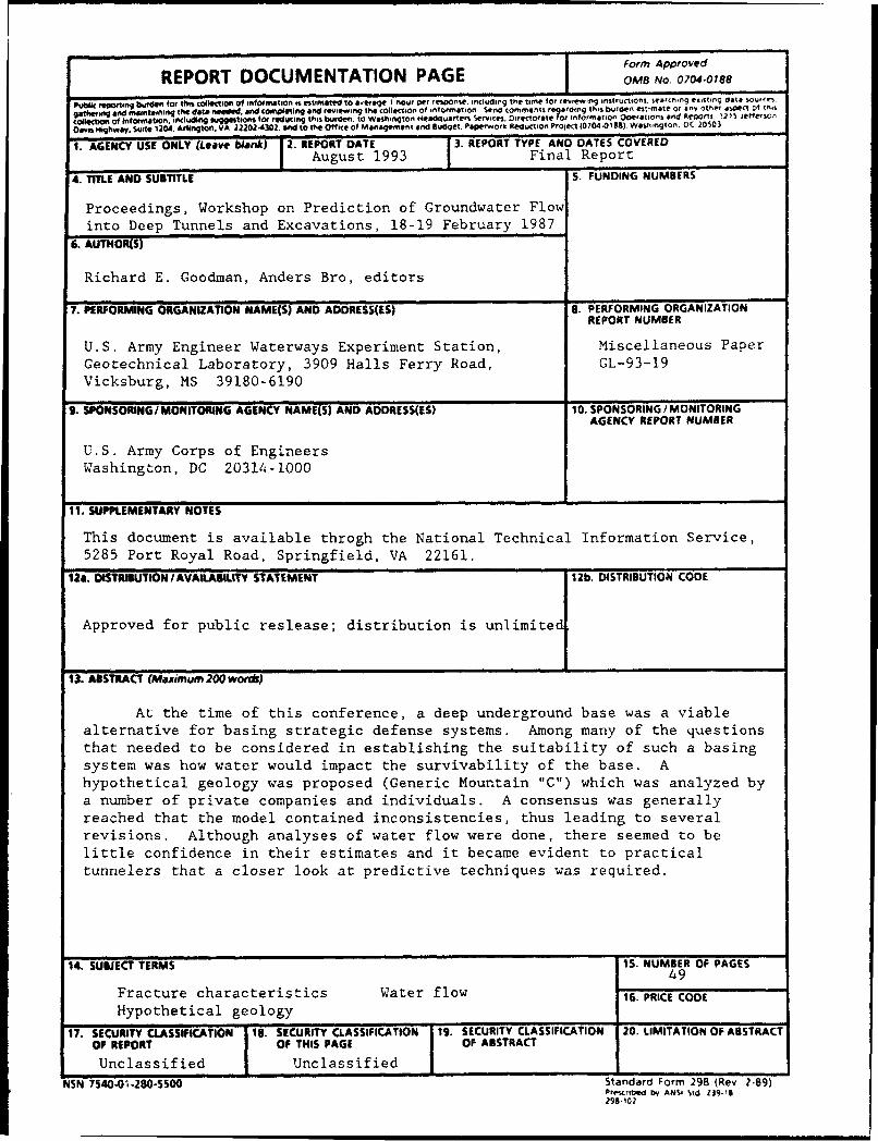
Form ApprovedREPORT DOCUMENTATION PAGE 0M8 N .o074-18
ur nIIIfor tI hos oer = = = InIIlll I In tructioni. Sea hrIg tI ng data souron.
g atf wnitgh a n d eta' i n ni"n- t h e d ate It qd d h a n d CO tfq Ef i d re ilew in g t e co lle tio n o f in fo rm ato n .e n d co m meotf rel a rd in g th is b u rd e n e itm a te o r a n t o th e r a sp e c t o f m 4,
c •olfOn nof Inf bon., icluqing si g iotlns tot reducing this burden. to Washington Headquarters Services. Directorate for Information Operations and ACOO ItI. 12 15 ercrt
Oam•nHighway, Suite 1204. Ar ington. VA 22024302. and to te Office of Management and Budget. Papervwork Reduction Project (0704-0188). WashingtOn, 0C 20503
1. AGENCY USE ONLY (Leave biank) 2. REPORT DATE 3. REPORT TYPE AND DATES COVERED
August 1993 Final Report
4. TITLE AND SUBTITLE S. FUNDING NUMBERS
Proceedings, Workshop on Prediction of Groundwater Flowinto Deep Tunnels and Excavations, 18-19 February 1987
6. AUTHOR(S)
Richard E. Goodman, Anders Bro, editors
7. PERFORMING ORGANIZATION NAME(S) AND ADDRESS(IS) B. PERFORMING ORGANIZATIONREPORT NUMBER
U.S. Army Engineer Waterways Experiment Station, Miscellaneous PaperGeotechnical Laboratory, 3909 Halls Ferry Road, GL-93-19Vicksburg, MS 39180-6190
9. SPONSORING/MONITORING AGENCY NAME(S) AND ADDRESS(ES) 10. SPONSORINGIMONITORINGAGENCY REPORT NUMBER
U.S. Army Corps of EngineersWashington, DC 20314-1000
11. SUPPLEMENTARY NOTES
This document is available throgh the National Technical Information Service,5285 Port Royal Road, Springfield, VA 22161.
12a. DISTRIBUTION/ AVAILASILITY STATEMENT 12b, DISTRIBUTION CODE
Approved for public reslease; distribution is unlimited1
13. ABSTRACT (Maximum 200 words)
At the time of this conference, a deep underground base was a viablealternative for basing strategic defense systems. Among many of the questionsthat needed to be considered in establishing the suitability of such a basingsystem was how water would impact the survivability of the base. Ahypothetical geology was proposed (Generic Mountain "C") which was analyzed bya number of private companies and individuals. A consensus was generallyreached that the model contained inconsistencies, thus leading to severalrevisions. Although analyses of water flow were done, there seemed to belittle confidence in their estimates and it became evident to practicaltunnelers that a closer look at predictive techniques was required.
14. SUBJECT TERMS 15. NUMBER OF PAGES
49Fracture characteristics Water flow 16. PRICE CODE
Hypothetical geology
17. SECURITY CLASSIFICATION 18. SECURITY CLASSIFICATION 19. SECURITY CLASSIFICATION 20. LIMITATION OF ABSTRACTOF REPORT OF THIS PAGE OF ABSTRACT
Unclassified Unclassified I
NSN 7540-01-280-5500 Standard Form 298 (Rev 2-89)Prescribed by ANSI Std Z19-I1299.102