Embed Size (px)
Citation preview
Multi-Disciplinary Senior Design ConferenceKate Gleason College of Engineering
Rochester Institute of TechnologyRochester, New York 14623
Project Number: 11462
THERMOELECTRIC AND FAN SYSTEM FOR COOK STOVE
Jared Rugg / Project Lead Thomas Gorevski / Electrical Engineer
Bradley Sawyer / Lead Engineer Fahad Masood / Electrical Engineer
Jeffrey Bird / Mechanical Engineer
ABSTRACT
The objective of this project was to design a thermoelectric module to be coupled with an existing Haitian style cook stove. The purpose for this project is to work toward a dependable and affordable unit that could be used in Haiti. The unit would not only increase the efficiency of the stove, but also generate power for its own fan and possibly auxiliary charging. The target market for Haiti would be vendors cooking large quantities of food and over long periods of time. The vendors cooking habits would allow for the most power generation through heat. A design was implemented which utilizes an axial fan to provide airflow into the stove. Heat energy is taken from the combustion chamber via a steel rod. The heat energy is converted to electrical energy by the thermoelectric unit. The unit was tested rigorously and its strengths and weaknesses became apparent. A significant temperature differential was able to be maintained across the thermoelectric unit but the desired temperature differential was not achieved. The main issue with the system is how the limited power provided by the thermoelectric is budgeted between the components and loads. The thermoelectric unit was able to power the fan, and therefore the system is self-sustaining to a certain degree. Improvements to both the thermal system and the electrical system could be made to increase the functionality of the system.
NOMENCLATURE
CFM cubic feet per minutePWM Pulse Width ModulationTEG thermoelectric generatorh convection coefficientDh hydraulic diameter
INTRODUCTION
Billions of people around the world depend on biomass for everyday cooking fuel. Cooking is often performed on a semi-open stove or over a simple three-stone fire. These methods of cooking are very inefficient and lead to high fuel usage and airborne pollution. Cooking is often performed indoors and therefore the use of biomass cooking has a negative impact on the health of people who must live in the heavily polluted air conditions. Inefficient cooking methods have especially had a major impact on Haiti, the poorest country in the western hemisphere. Haiti was once covered with forests, but is now less than 4% forested. Much of the deforestation is a result of the need for cooking fuel. The most popular fuel used in Haiti is charcoal.
The introduction of oxygen to any combustion process will, in general, allow for more efficient, complete and clean combustion. The primary function of the thermoelectric and fan system is to
Copyright © 2008 Rochester Institute of Technology
Proceedings of the Multi-Disciplinary Senior Design Conference Page 2
provide forced airflow to the combustion chamber of the cook stove without the need of an external power source. A thermoelectric unit is utilized to convert thermal energy taken from the combustion process into electrical energy. Electrical energy provided by the thermoelectric unit is used to power a fan and a USB port. The USB port can be used to charge the batteries of an ‘auxiliary’ device such as a cell phone.
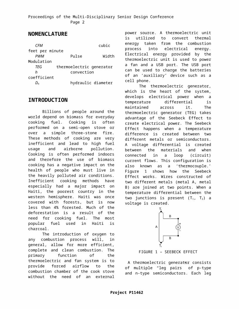
The thermoelectric generator, which is the heart of the system, develops electrical power when a temperature differential is maintained across it. The thermoelectric generator (TEG) takes advantage of the Seebeck Effect to create electrical power. The Seebeck Effect happens when a temperature difference is created between two different metals or semiconductors. A voltage differential is created between the materials and when connected in a loop (circuit) current flows. This configuration is also known as a ‘thermocouple.’ Figure 1 shows how the Seebeck Effect works. Wires constructed of two different metals (metal A, metal B) are joined at two points. When a temperature differential between the two junctions is present (T1, T2) a voltage is created.
FIGURE 1 – SEEBECK EFFECT
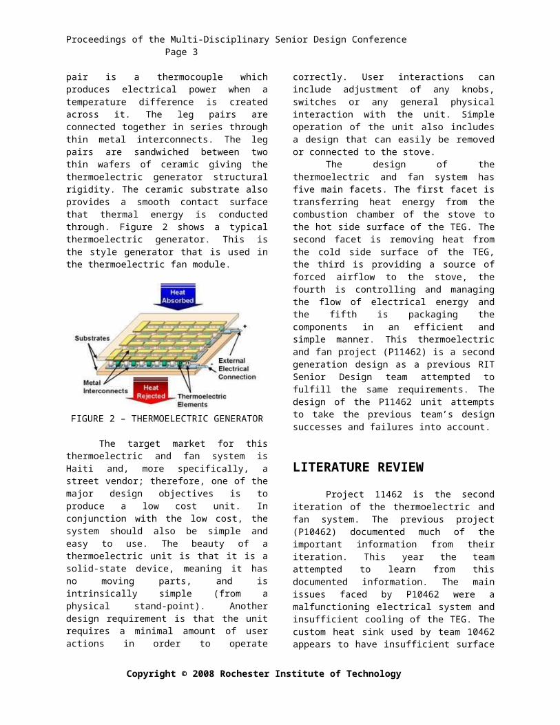
A thermoelectric generator consists of multiple “leg pairs” of p-type and n-type semiconductors. Each leg pair is a thermocouple which produces electrical power when a temperature difference is created across it. The leg pairs are connected together in series through thin metal interconnects. The leg pairs are sandwiched between two thin wafers of ceramic giving the thermoelectric generator structural rigidity. The ceramic substrate also provides a smooth contact surface that thermal energy is conducted through. Figure 2 shows a typical thermoelectric generator. This is the style generator that is used in the thermoelectric fan module.
FIGURE 2 – THERMOELECTRIC GENERATOR
The target market for this thermoelectric and fan system is Haiti and, more specifically, a street vendor; therefore, one of the major design objectives is to produce a low cost unit. In conjunction with the low cost, the system should also be simple and easy to use. The beauty of a thermoelectric unit is that it is a solid-state device, meaning it has no moving parts, and is intrinsically simple (from a physical stand-point). Another design requirement is that the unit requires a minimal amount of user actions in order to operate correctly. User interactions can include adjustment of any knobs, switches or any general physical interaction with the unit. Simple operation of the unit also includes a design that can easily be removed or connected to the stove.
The design of the thermoelectric and fan system has five main facets. The first facet is transferring heat energy from the combustion chamber of the stove to the hot side surface of the TEG. The second facet is removing heat from the cold side surface of the TEG, the third is providing a source of forced airflow to the stove, the fourth is controlling and managing the flow of electrical energy and the fifth is packaging the components in an efficient and simple manner. This thermoelectric and fan project (P11462) is a second generation design as a previous RIT Senior Design team attempted to fulfill the same requirements. The design of the P11462 unit attempts to take the previous team’s design successes and failures into account.
LITERATURE REVIEW
Project 11462 is the second iteration of the thermoelectric and fan system. The previous project (P10462) documented much of the important information from their iteration. This year the team attempted to learn from this documented information. The main issues faced by P10462 were a malfunctioning electrical system and insufficient cooling of the TEG. The custom heat sink used by
Project P11462
Proceedings of the Multi-Disciplinary Senior Design Conference Page 3
team 10462 appears to have insufficient surface area; a fact echoed in their technical write-up. In addition, use of a simple bent metal fan may have provided too low a flow for proper cooling. Another issue that was mentioned was a suspected problem with thermal resistances between the ceramic substrate of the TEG and the surfaces of the thermal bridge (heat conduction rod) and heat sink. The team felt that heat was not being conducted well between the ceramic substrate of the TEG and the surfaces on the conduction rod and heat sink.
On the electrical front, team 10426 experienced multiple problems with managing the power allowances between the electrical devices. An important consideration that was discovered through reading the research by previous thermoelectric teams was that the thermoelectric must be operated in a range where it can provide sufficient power. While mainly the shortcomings of team 10462’s design have been addressed, several test methods from their design process were also used. A similar approach is used to better model and empirically determine the heat transfer coefficient of the fire. Also, ideas for determining the flow rate out of the combustion chamber of the stove are used.
PROCESS
The final proposed design was the result of careful consideration of past team experiences, pairwise comparisons of possible solutions, and first principle feasibility calculations. The design process was driven by several important customer needs. First, the system needed to provide forced airflow into the current stove (P10461). As stated earlier the system had to work with a charcoal fire and have a relatively cheap cost. Fourth, the customer wanted the system to require no user interaction to protect the system. P10462 planned to use an LED light to tell the user that the system was overheating. The customer did not like this approach and wanted to reduce the reliance on untrained users. Additionally, for obvious reasons the proposed system needed to be safe to operate and easily transportable. Finally, use of a thermoelectric device was required.
From these customer needs several engineering specifications were developed. Ideally, the final proposed design must be able to satisfy all of these specs. First, the flow rate of the air into the stove must be marginally 0.3-0.7 kg/min. Second, the unit must cost $27.50 or less. Finally, based on the properties of the TEG the maximum temperature of the hot side of the TEG is 275°C. Several less important engineer specifications also were developed and helped to drive the design of the system.
With these customer needs and engineering specifications in mind, functions were determined for the various portions of the system. For example one function of the system is to provide air to the stove fire. In all, 13 functions were enumerated. For each function different ways to satisfy the function were determined during brainstorming sessions. For example, for the provide air to the stove fire function a fan, compressed air source, and bellows were brainstormed.
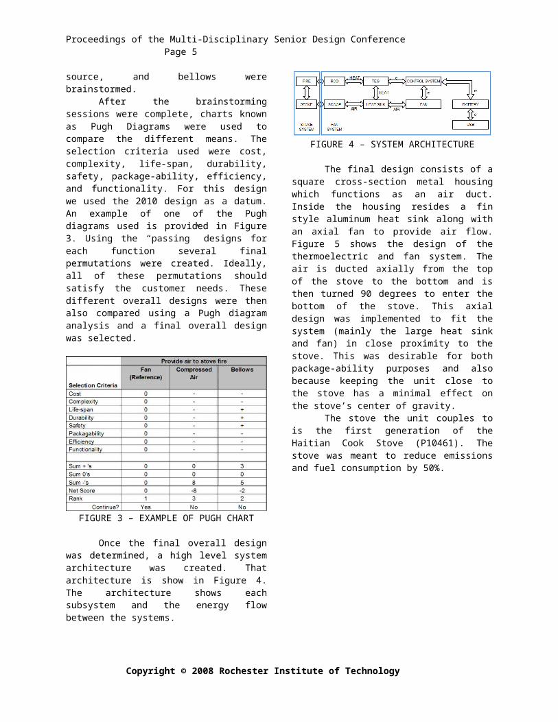
After the brainstorming sessions were complete, charts known as Pugh Diagrams were used to compare the different means. The selection criteria used were cost, complexity, life-span, durability, safety, package-ability, efficiency, and functionality. For this design we used the 2010 design as a datum. An example of one of the Pugh diagrams used is provided in Figure 3. Using the “passing” designs for each function several final permutations were created. Ideally, all of these permutations should satisfy the customer needs. These different overall designs were then also compared using a Pugh diagram analysis and a final overall design was selected.
FIGURE 3 – EXAMPLE OF PUGH CHART
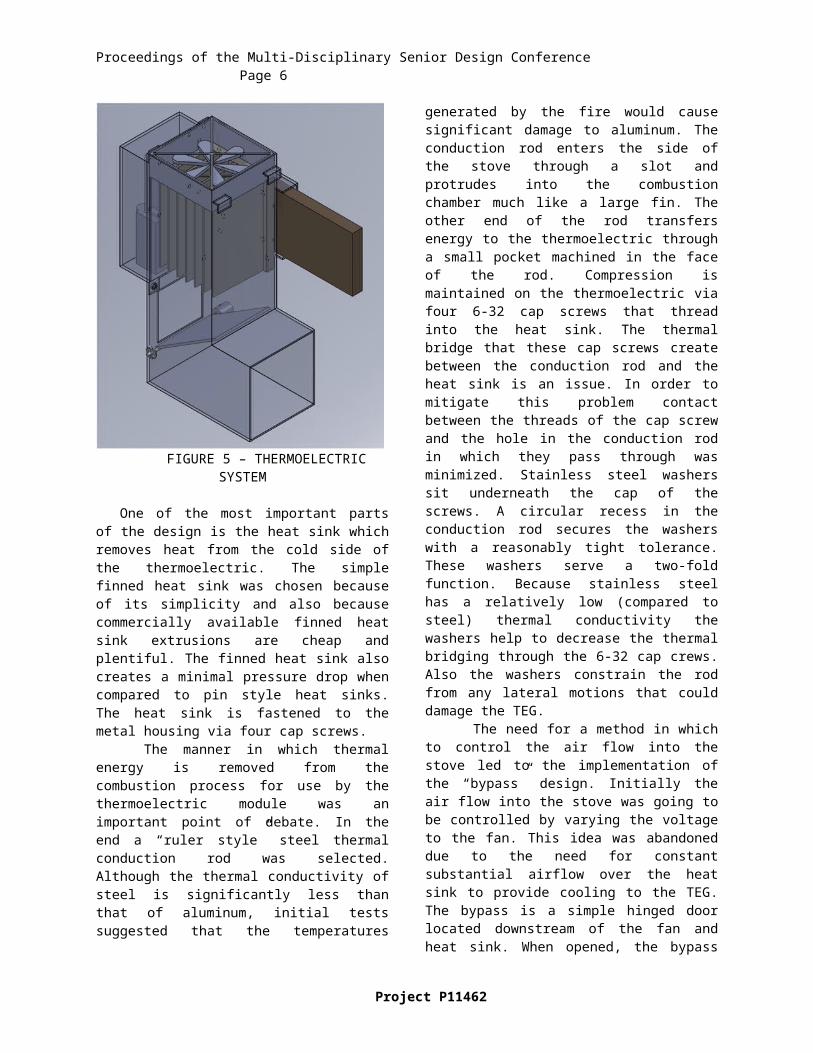
Once the final overall design was determined, a high level system architecture was created. That architecture is show in Figure 4. The architecture shows each subsystem and the energy flow between the systems.
FIGURE 4 – SYSTEM ARCHITECTURE
The final design consists of a square cross-section metal housing which functions as an air duct.
Copyright © 2008 Rochester Institute of Technology
Proceedings of the Multi-Disciplinary Senior Design Conference Page 4
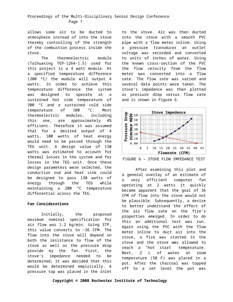
Inside the housing resides a fin style aluminum heat sink along with an axial fan to provide air flow. Figure 5 shows the design of the thermoelectric and fan system. The air is ducted axially from the top of the stove to the bottom and is then turned 90 degrees to enter the bottom of the stove. This axial design was implemented to fit the system (mainly the large heat sink and fan) in close proximity to the stove. This was desirable for both package-ability purposes and also because keeping the unit close to the stove has a minimal effect on the stove’s center of gravity.
The stove the unit couples to is the first generation of the Haitian Cook Stove (P10461). The stove was meant to reduce emissions and fuel consumption by 50%.
FIGURE 5 – THERMOELECTRIC SYSTEM
One of the most important parts of the design is the heat sink which removes heat from the cold side of the thermoelectric. The simple finned heat sink was chosen because of its simplicity and also because commercially available finned heat sink extrusions are cheap and plentiful. The finned heat sink also creates a minimal pressure drop when compared to pin style heat sinks. The heat sink is fastened to the metal housing via four cap screws.
The manner in which thermal energy is removed from the combustion process for use by the thermoelectric module was an important point of debate. In the end a “ruler style” steel thermal conduction rod was selected. Although the thermal conductivity of steel is significantly less than that of
aluminum, initial tests suggested that the temperatures generated by the fire would cause significant damage to aluminum. The conduction rod enters the side of the stove through a slot and protrudes into the combustion chamber much like a large fin. The other end of the rod transfers energy to the thermoelectric through a small pocket machined in the face of the rod. Compression is maintained on the thermoelectric via four 6-32 cap screws that thread into the heat sink. The thermal bridge that these cap screws create between the conduction rod and the heat sink is an issue. In order to mitigate this problem contact between the threads of the cap screw and the hole in the conduction rod in which they pass through was minimized. Stainless steel washers sit underneath the cap of the screws. A circular recess in the conduction rod secures the washers with a reasonably tight tolerance. These washers serve a two-fold function. Because stainless steel has a relatively low (compared to steel) thermal conductivity the washers help to decrease the thermal bridging through the 6-32 cap crews. Also the washers constrain the rod from any lateral motions that could damage the TEG.
The need for a method in which to control the air flow into the stove led to the implementation of the “bypass” design. Initially the air flow into the stove was going to be controlled by varying the voltage to the fan. This idea was abandoned due to the need for constant substantial airflow over the heat sink to provide cooling to the TEG. The bypass is a simple hinged door located downstream of the fan and heat sink. When opened, the bypass allows some air to be ducted to atmosphere instead of into the stove thereby controlling of the strength of the combustion process inside the stove.
The thermoelectric module (Taihuaxing TEP-1264-1.5) used for this project is a 4 watt module. At a specified temperature difference (200 °C) the module will output 4 watts. In order to achieve this temperature difference the system was designed to operate at a sustained hot side temperature of 300 °C and a sustained cold side temperature of 100 °C. Most thermoelectric modules, including this one, are approximately 4% efficient. Therefore it was assumed that for a desired output of 4 watts, 100 watts of heat energy would need to be passed through the TEG unit. A design value of 130 watts was estimated to account for thermal losses in the system and for losses in the TEG unit. Once these design parameters were selected, the conduction rod and heat sink could be designed to pass 130 watts of energy through the TEG while maintaining a 200 °C temperature differential across the TEG.
Fan Considerations
Project P11462
Proceedings of the Multi-Disciplinary Senior Design Conference Page 5
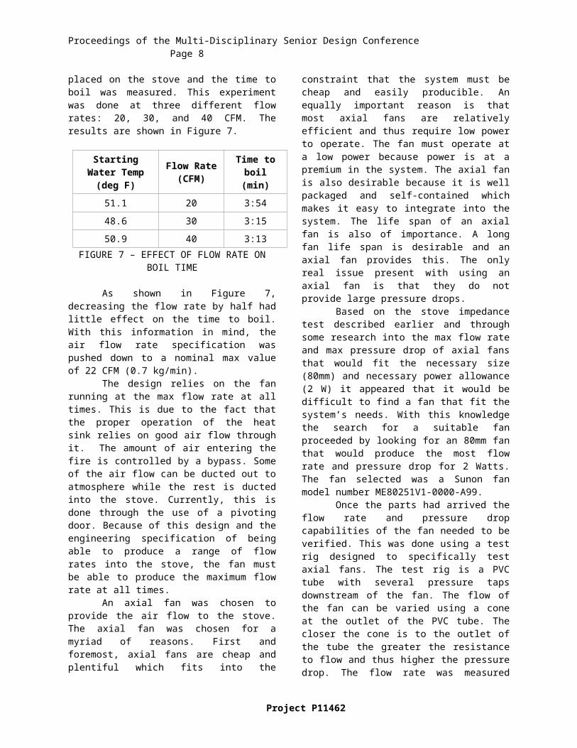
Initially, the proposed maximum nominal specification for air flow was 1.2 kg/min. Using STP, this value converts to ~36 CFM. The flow into the stove will depend on both the resistance to flow of the stove as well as the pressure drop provide by the fan. First, the stove’s impedance needed to be determined; it was decided that this would be determined empirically. A pressure tap was placed in the inlet to the stove. Air was then ducted into the stove with a smooth PVC pipe with a flow meter inline. Using a pressure transducer an outlet voltage was recorded and converted to units of inches of water. Using the known cross-section of the PVC the flow velocity from the flow meter was converted into a flow rate. The flow rate was varied and several data points were taken. The stove’s impedance was then plotted as pressure drop versus flow rate and is shown in Figure 6.
0 5 10 15 20 25 30 35 40 450.00
0.10
0.20
0.30
0.40
0.50
0.60Stove Impedence
Flowrate (CFM)
Pres
sure
Dro
p (in
ches
H2O
)
FIGURE 6 – STOVE FLOW IMPEDANCE TEST
After examining this plot and a general overlay of an estimate of a very efficient computer fan operating at 2 watts it quickly became apparent that the goal of 36 CFM of flow into the stove would not be plausible. Subsequently, a desire to better understand the effect of the air flow rate on the fire’s properties emerged. In order to do this an additional test was run. Again using the PVC with the flow meter inline to duct air into the stove, a fire was started in the stove and the stove was allowed to reach a “hot start” temperature. Next, 2 L of water at room temperature (50 F) was placed in a pot. After the charcoal was topped off to a set level the pot was placed on the stove and the time to boil was measured. This experiment was done at three different flow rates: 20, 30, and 40 CFM. The results are shown in Figure 7.
Starting Water Temp (deg F)
Flow Rate (CFM)
Time to boil (min)
51.1 20 3:54
48.6 30 3:15
50.9 40 3:13FIGURE 7 – EFFECT OF FLOW RATE ON BOIL
TIME
As shown in Figure 7, decreasing the flow rate by half had little effect on the time to boil. With this information in mind, the air flow rate specification was pushed down to a nominal max value of 22 CFM (0.7 kg/min).
The design relies on the fan running at the max flow rate at all times. This is due to the fact that the proper operation of the heat sink relies on good air flow through it. The amount of air entering the fire is controlled by a bypass. Some of the air flow can be ducted out to atmosphere while the rest is ducted into the stove. Currently, this is done through the use of a pivoting door. Because of this design and the engineering specification of being able to produce a range of flow rates into the stove, the fan must be able to produce the maximum flow rate at all times.
An axial fan was chosen to provide the air flow to the stove. The axial fan was chosen for a myriad of reasons. First and foremost, axial fans are cheap and plentiful which fits into the constraint that the system must be cheap and easily producible. An equally important reason is that most axial fans are relatively efficient and thus require low power to operate. The fan must operate at a low power because power is at a premium in the system. The axial fan is also desirable because it is well packaged and self-contained which makes it easy to integrate into the system. The life span of an axial fan is also of importance. A long fan life span is desirable and an axial fan provides this. The only real issue present with using an axial fan is that they do not provide large pressure drops.
Based on the stove impedance test described earlier and through some research into the max flow rate and max pressure drop of axial fans that would fit the necessary size (80mm) and necessary power allowance (2 W) it appeared that it would be difficult to find a fan that fit the system’s needs. With this knowledge the search for a suitable fan proceeded by looking for an 80mm fan that would produce the most flow rate and pressure drop for 2 Watts. The fan selected was a Sunon fan model number ME80251V1-0000-A99.
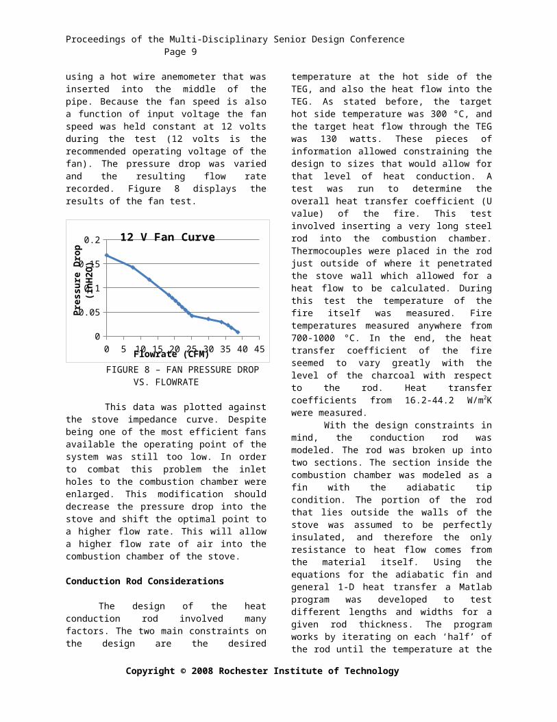
Once the parts had arrived the flow rate and pressure drop capabilities of the fan needed to be verified. This was done using a test rig designed to specifically test axial fans. The test rig is a PVC tube with several pressure taps downstream of the fan. The flow of the fan can be varied using a cone at the outlet of the PVC tube. The closer the cone is to the outlet of the tube the greater the resistance to flow and thus higher the pressure drop. The flow rate was measured using a hot wire anemometer that was inserted into the middle of the pipe. Because the fan speed is also a function of input voltage the fan speed was held constant at 12 volts during the test (12 volts is the
Copyright © 2008 Rochester Institute of Technology
Proceedings of the Multi-Disciplinary Senior Design Conference Page 6
recommended operating voltage of the fan). The pressure drop was varied and the resulting flow rate recorded. Figure 8 displays the results of the fan test.
0 5 10 15 20 25 30 35 40 450
0.020.040.060.08
0.10.120.140.160.18 12 V Fan Curve
Flowrate (CFM)
Pres
sure
Dro
p (in
H2O
)
FIGURE 8 – FAN PRESSURE DROP VS. FLOWRATE
This data was plotted against the stove impedance curve. Despite being one of the most efficient fans available the operating point of the system was still too low. In order to combat this problem the inlet holes to the combustion chamber were enlarged. This modification should decrease the pressure drop into the stove and shift the optimal point to a higher flow rate. This will allow a higher flow rate of air into the combustion chamber of the stove.
Conduction Rod Considerations
The design of the heat conduction rod involved many factors. The two main constraints on the design are the desired temperature at the hot side of the TEG, and also the heat flow into the TEG. As stated before, the target hot side temperature was 300 °C, and the target heat flow through the TEG was 130 watts. These pieces of information allowed constraining the design to sizes that would allow for that level of heat conduction. A test was run to determine the overall heat transfer coefficient (U value) of the fire. This test involved inserting a very long steel rod into the combustion chamber. Thermocouples were placed in the rod just outside of where it penetrated the stove wall which allowed for a heat flow to be calculated. During this test the temperature of the fire itself was measured. Fire temperatures measured anywhere from 700-1000 °C. In the end, the heat transfer coefficient of the fire seemed to vary greatly with the level of the charcoal with respect to the rod. Heat transfer coefficients from 16.2-44.2 W/m2K were measured.
With the design constraints in mind, the conduction rod was modeled. The rod was broken up into two sections. The section inside the combustion
chamber was modeled as a fin with the adiabatic tip condition. The portion of the rod that lies outside the walls of the stove was assumed to be perfectly insulated, and therefore the only resistance to heat flow comes from the material itself. Using the equations for the adiabatic fin and general 1-D heat transfer a Matlab program was developed to test different lengths and widths for a given rod thickness. The program works by iterating on each ‘half’ of the rod until the temperature at the meeting points of the halves (which occurs at the outer wall of the stove) is equal. This means that the amount of heat flux that the fin part of the rod is transferring to the insulated part of the rod is the correct amount to achieve a 300 °C TEG hot side temperature.
Heat Sink Considerations
The heat sink was designed to maintain a TEG cold side temperature of 100 °C while dissipating the 130 watts of energy coming from the TEG unit. Some of the assumptions made were a worse case of 30 °C ambient air temperature and a constant flow of 20 CFM over the heat sink. In order to calculate the heat transfer characteristics of the heat sink the convection coefficient (h) must be calculated. The flow between the fins of the heat sink was modeled as internal, fully developed flow with ℜD=5660. With this Reynolds number, the ‘h’ value can be calculated using the following equation:
Nu=hLk
=.023(5660)45 (.707)0.3 (1)
The convection coefficient was calculated to be:
h=20.85 Wm2 K
Once the ‘h’ value of the heat sink is calculated, the dimensions of the heat sink determine its thermal resistance. The thermal resistance of the heat sink used in the thermoelectric system is 0.52. Based on
ELECTRICAL
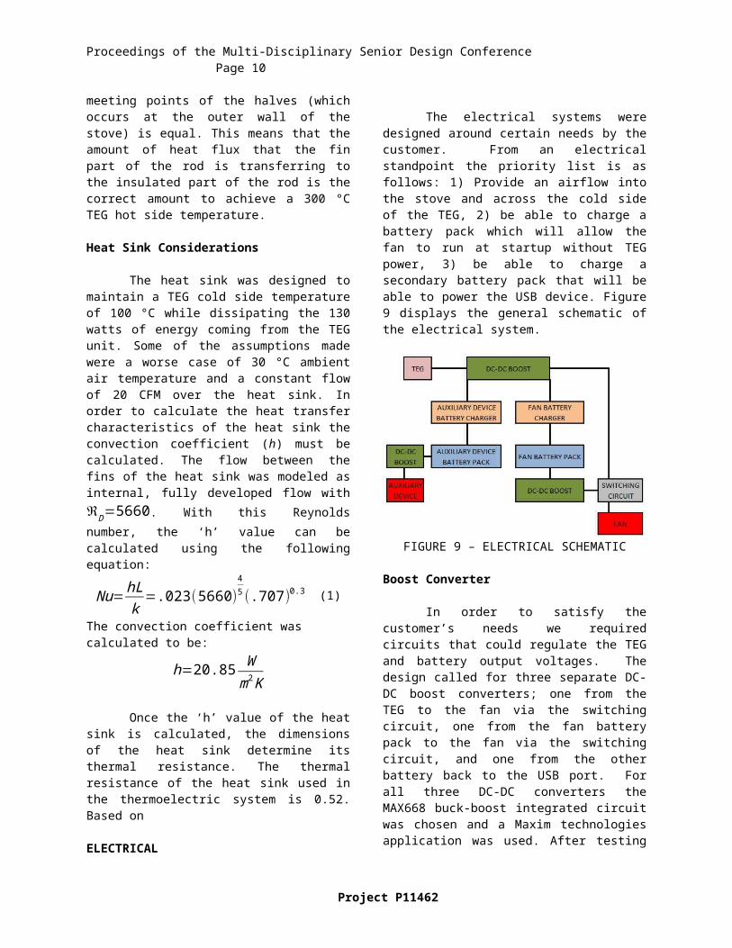
The electrical systems were designed around certain needs by the customer. From an electrical standpoint the priority list is as follows: 1) Provide an airflow into the stove and across the cold side of the TEG, 2) be able to charge a battery pack which will allow the fan to run at startup without TEG power, 3) be able to charge a secondary battery pack that will be able to power the USB device. Figure 9 displays the general schematic of the electrical system.
Project P11462
Proceedings of the Multi-Disciplinary Senior Design Conference Page 7
FIGURE 9 – ELECTRICAL SCHEMATIC
Boost Converter
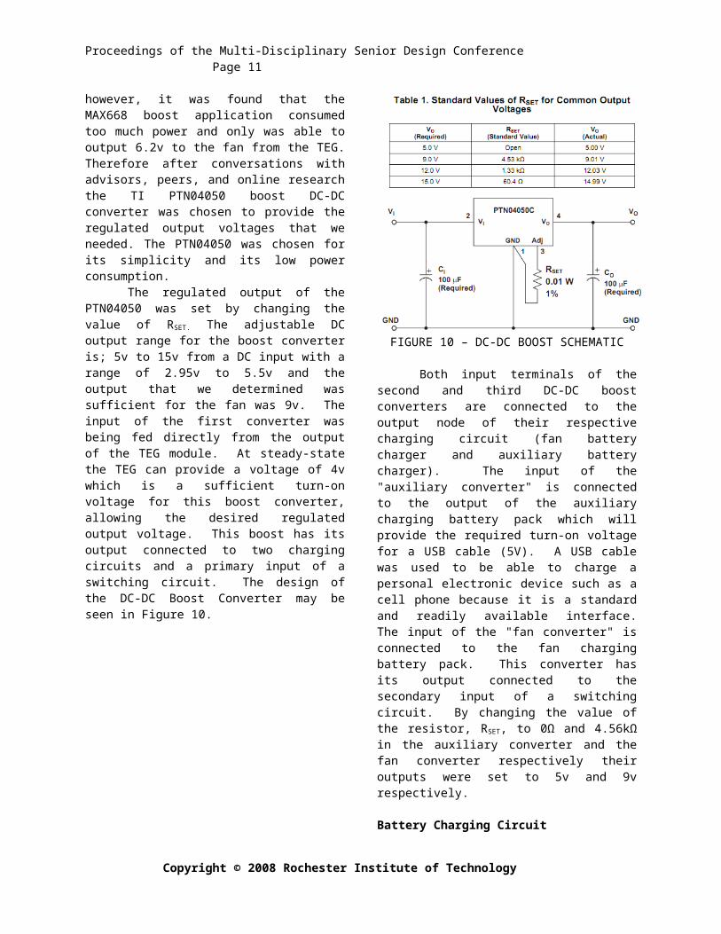
In order to satisfy the customer’s needs we required circuits that could regulate the TEG and battery output voltages. The design called for three separate DC-DC boost converters; one from the TEG to the fan via the switching circuit, one from the fan battery pack to the fan via the switching circuit, and one from the other battery back to the USB port. For all three DC-DC converters the MAX668 buck-boost integrated circuit was chosen and a Maxim technologies application was used. After testing however, it was found that the MAX668 boost application consumed too much power and only was able to output 6.2v to the fan from the TEG. Therefore after conversations with advisors, peers, and online research the TI PTN04050 boost DC-DC converter was chosen to provide the regulated output voltages that we needed. The PTN04050 was chosen for its simplicity and its low power consumption.
The regulated output of the PTN04050 was set by changing the value of RSET. The adjustable DC output range for the boost converter is; 5v to 15v from a DC input with a range of 2.95v to 5.5v and the output that we determined was sufficient for the fan was 9v. The input of the first converter was being fed directly from the output of the TEG module. At steady-state the TEG can provide a voltage of 4v which is a sufficient turn-on voltage for this boost converter, allowing the desired regulated output voltage. This boost has its output connected to two charging circuits and a primary input of a switching circuit. The design of the DC-DC Boost Converter may be seen in Figure 10.
FIGURE 10 – DC-DC BOOST SCHEMATIC
Both input terminals of the second and third DC-DC boost converters are connected to the output node of their respective charging circuit (fan battery charger and auxiliary battery charger). The input of the "auxiliary converter" is connected to the output of the auxiliary charging battery pack which will provide the required turn-on voltage for a USB cable (5V). A USB cable was used to be able to charge a personal electronic device such as a cell phone because it is a standard and readily available interface. The input of the "fan converter" is connected to the fan charging battery pack. This converter has its output connected to the secondary input of a switching circuit. By changing the value of the resistor, RSET, to 0Ω and 4.56kΩ in the auxiliary converter and the fan converter respectively their outputs were set to 5v and 9v respectively.
Battery Charging Circuit
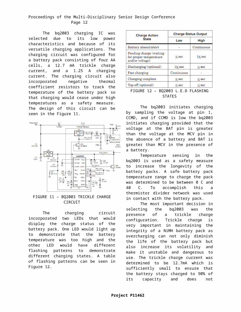
The bq2003 charging IC was selected due to its low power characteristics and because of its versatile charging applications. The charging circuit was configured for a battery pack consisting of four AA cells, a 12.7 mA trickle charge current, and a 1.25 A charging current. The charging circuit also incorporated negative thermal coefficient resistors to track the temperature of the battery pack so that charging would cease under high temperatures as a safety measure. The design of this circuit can be seen in the Figure 11.
Copyright © 2008 Rochester Institute of Technology
Proceedings of the Multi-Disciplinary Senior Design Conference Page 8
FIGURE 11 – BQ2003 TRICKLE CHARGE CIRCUIT
The charging circuit incorporated two LEDs that would display the charge status of the battery pack. One LED would light up to demonstrate that the battery temperature was too high and the other LED would have different flashing patterns to demonstrate different charging states. A table of flashing patterns can be seen in Figure 12.
FIGURE 12 – BQ2003 L.E.D FLASHING STATES
The bq2003 initiates charging by sampling the voltage at pin 1, CCMD, and if CCMD is low the bq2003 initiates charging provided that the voltage at the BAT pin is greater than the voltage at the MCV pin in the absence of a battery and BAT is greater than MCV in the presence of a battery.
Temperature sensing in the bq2003 is used as a safety measure to increase the longevity of the battery packs. A safe battery pack temperature range to charge the pack was determined to be between 0 C and 40 C. To accomplish this a thermistor divider network was used in contact with the battery pack.
The most important decision in selecting the bq2003 was the presence of a trickle charge configuration. Trickle charge is very important in maintaining the integrity of a NiMH battery pack as
overcharging can not only diminish the life of the battery pack but also increase its volatility and make it unstable and dangerous to use. The trickle charge current was determined to be 12.7mA which is sufficiently small to ensure that the battery stays charged to 90% of its capacity and does not overcharge. The trickle charge is set by changing the resistor value of R10 which, the current across this resistor is determined to be the trickle charge current into the battery.
The battery packs were chosen with certain constraints in mind: it had to power the fan at startup, be robust, and be affordable. To satisfy these constraints two battery packs were chosen: one with four AA NiMH cells to charge the auxiliary device and the other containing three AA NiMH cells to run the fan at startup. The chemistry of rechargeable batteries was taken into consideration and the NiMH chemistry was chosen due to its lack of memory, high energy density, and relative low cost. A comparison of the two feasible battery packs is shown in Figure 13
. NiMH NiCd
Capacity (mAh) 1100-3000 500-1000Density (Wh/L) 140-300 50-150
Service Life Up to 1000 Cycles
Up to 750 Cycles
FIGURE 13 – BATTERY COMPARISON
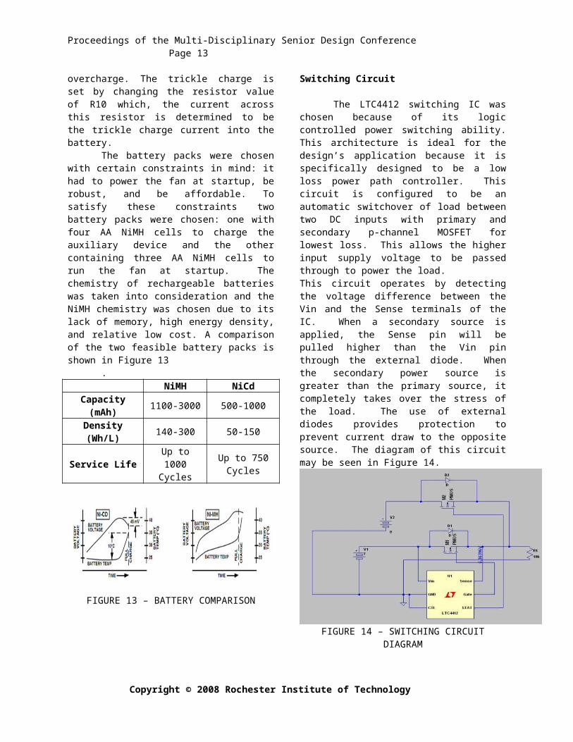
Switching Circuit
The LTC4412 switching IC was chosen because of its logic controlled power switching ability. This architecture is ideal for the design’s application because it is specifically designed to be a low loss power path controller. This circuit is configured to be an automatic switchover of load between two DC inputs with primary and secondary p-channel MOSFET for lowest loss. This allows the higher input supply voltage to be passed through to power the load.This circuit operates by detecting the voltage difference between the Vin and the Sense terminals of the IC. When a secondary source is applied, the Sense
Project P11462
Proceedings of the Multi-Disciplinary Senior Design Conference Page 9
pin will be pulled higher than the Vin pin through the external diode. When the secondary power source is greater than the primary source, it completely takes over the stress of the load. The use of external diodes provides protection to prevent current draw to the opposite source. The diagram of this circuit may be seen in Figure 14.
FIGURE 14 – SWITCHING CIRCUIT DIAGRAM
RESULTS AND DISCUSSION
Multiple ‘live fire’ tests were performed with the thermoelectric unit connected to the stove. Thermocouples were inserted into holes drilled in both the conduction rod and the heat sink. These holes were drilled so that the tip of the thermocouple lies just under the surface of where the thermoelectric is seated. Figure 15 demonstrates some of the temperature data collected during these tests. It must be kept in mind that these tests were performed under different system configurations and different ambient conditions, but the data seems to be consistent across different tests.
0.00 10.00 20.00 30.00 40.000
50
100
150
200
250
Temperatures
4-8 Cold Side
4-8 Hot Side
4-8 Delta T
4-14 Delta T
4-14 Hot Side
4-14 Cold Side
4-22 Delta T
4-22 Hot Side
4-22 Cold Side
Time (min)
Tem
p (D
eg C
)
FIGURE 15 - TEG TEMPERATURES
The plots near the top of Figure 15 (red) represent the hot side temperatures on the TEG. The
plots near the bottom (blue) of the graph represent the TEG cold side temperatures and the middle plots (green) represent the temperature difference between the two. The data in Figure 15 shows that the desired 200 °C temperature difference was never realized. The maximum sustained TEG temperature difference was approximately 140 °C. This could be blamed on the fact that the hot side temperatures never reached more than 250 °C, but the larger hidden problem is that the cold side temperature approached 100 °C with a hot side temperature of only 250 °C. This begs the question of what the cold side temperature would be if the hot side temperature was at the desired 300 °C. It can be assumed that the relationship between the hot side and cold side temperatures is linear and therefore at a hot side temperature of 300 °C the cold side temperature would be approximately 150 °C. The temperature data suggests that the heat dissipation capacity of the heat sink is insufficient. This could be attributed to not having enough fins on the heat sink, but more likely not having sufficient flow over the heat sink. This statement can be supported by the fact that when the bypass was opened, the cold side temperature dropped rapidly. When the bypass is opened, the impedance to fan flow is greatly reduced and therefore the flow over the heat sink is increased.
While performing the ‘live fire’ testing the thermoelectric was loaded with either a fan, a rheostat, or a fan and rheostat is in parallel. This was done because the TEG heat transfer characteristics change as the load on the TEG changes (see Conclusions and Recommendations for details). During each test the TEG was loaded with an equivalent load of 3-4 ohms because the internal resistance of the TEG is approximately 3 ohms. With the internal resistance of the TEG and the load resistance matched, the TEG will be operating at peak power. Figure 16 are results from three ‘live fire’ tests. It shows how the TEG power output varies with the temperature difference across the TEG. Keep in mind that the TEG is operating at peak power. The trend in Figure 16 is linear which is to be expected with a thermoelectric.
The advantage of loading the TEG with a rheostat is that the load resistance can be varied with ease. Figure 17 demonstrates how the power output of the TEG varies with load resistance for a given temperature difference. This is the main reason why the electrical system never functioned properly. The power produced by the TEG drops off dramatically as the load resistance increases from the internal resistance (approx. 3 ohms) of the TEG.
Copyright © 2008 Rochester Institute of Technology
Proceedings of the Multi-Disciplinary Senior Design Conference Page 10
0.00 50.00 100.00 150.00 200.000.00
0.50
1.00
1.50
2.00
2.50
3.00
3.50
4.00 TEG Power Output vs. Temperature Dif -ference
Delta T (Deg C)
Pow
er (W
atts)
FIGURE 16 – TEG POWER OUTPUT
0 20 40 60 80 100 1200
0.51
1.52
2.53
TEG Power vs. Load Resistance
Load Resistance (ohms)
Pow
er O
utpu
t (W
atts)
FIGURE 17 – EFFECT OF LOAD ON TEG
After a few tests and therefore thermal cycles on the TEG unit, the unit was torn down for inspection. Upon inspection, it was noticed that the conduction rod was able to be shimmied back and forth. This is not a good situation for two reasons; one, the TEG could be damaged, and two, this indicated that the compression on the TEG was compromised. Loss of compression effects the heat conduction into, and out of, the TEG. It was determined that the four cap screws that fasten the heat rod to the heat sink had loosened due to thermal cycling. To combat this problem the cap screws were lengthened and a stiff compression spring (die spring) was sandwiched between a washer under the head of the cap screw and the pocket machined in the conduction rod. The idea behind this is to keep a large amount of compression on the TEG even if the fasteners relax a bit. The die springs were installed knowing that the extreme temperatures of the conduction rod would most likely
have a detrimental effect on them. After another ‘live fire’ test the springs were checked. As was feared, the heat of the rod annealed the springs and they were ruined. Either a new method of ensuring compression on the rod needs to be implemented or insulating washers (ceramic) need to be placed under the springs to prevent heat transfer.
The sub-par TEG hot side temperatures were addressed by testing three different rod lengths during testing. In short, the length of the rod did not change the hot side temperatures observed. This made no logical sense. The larger the surface area of the rod in the fire, the more heat it should transfer. Finally, the placement of the thermocouples in the rod was questioned. The previous thermocouple holes came in from the butt end of the rod and ended at the center of the TEG. A new thermocouple hole was drilled which put the tip of the thermocouple at the edge of the TEG closest to the stove. When tested, it was discovered that the edge of the TEG closest to the stove was approximately 40-50 degrees Celsius warmer than the center of the TEG unit. This suggests that a large temperature gradient is present across the face of the TEG and this is due to the architecture of the rod.
ELECTRICAL
Each electrical sub-system was tested separately to be able to confirm their operation, then they were all tested together, and finally the electrical system was integrated with the mechanical system.
TEGUsing a DC power source in series with a 3
ohm resistor a TEG power source was simulated. This test setup greatly reduced the time it took to test the circuits with the power source and allowed proper testing under a realistic and varying power source.
After building and integrating our electrical system excluding the auxiliary circuit we found that the power output of the TEG, 2 watts, was not enough to maintain the entire electrical system. After trying to adjust the power consumption of the electrical systems it was determined that the TEG would not be able to power our electrical system due to difficulties in matching resistances between our TEG and our load which would maximize the TEG power output to 4 watts. The decision to not build a USB auxiliary circuit was made while keeping in mind time constraints and budgeting constraints, the decision was not made lightly but had to be made in order to ensure the operation of the other, more vital, electrical systems.
Boost Converter
Project P11462
Proceedings of the Multi-Disciplinary Senior Design Conference Page 11
Initial testing with the MAX668 DC-DC converter was successful when using a resistive load; the MAX668 regulated output was 12 volts with an input of 3 volts to 15 volts. However, when the MAX668 was tested with the fan as the load it was found that the maximum output voltage of the buck-boost was only 6.2 volts, since 6.2 votls was determined to be too low for successful operation of the fan the PTN04050 was chosen.
Once again, initial testing with the boost converter proved successful when using a resistive load; however when the fan was attached to the output the output voltage dropped from 12 volts to a maximum of 9.5 volts. This voltage was sufficient to provide the fan with enough power to successfully force air into the stove, though not ideal.
After testing with the two DC-DC converters and a variety of loads it was determined that the boost converters could not supply enough power to the fan due to the fan being an inductive load. The reason the MAX668 did not provide a sufficient output like the PTN04050 is because the MAX668 application consumed more power than the PTN04050. A table of test results can be seen in Figure18 for the PTN04050 using a DC power supply in series with a resistor. The highlighted portion is the range of operation for the boost converter.
FIGURE 18 – MAX688 BOOST PERFORMANCE TABLE
The boost converter did not work correctly when supplied by the battery pack. Because of this the system was not operational at startup. The boost converter would output only a minor increase in voltage for the battery pack attached and this was a problem that befuddled not only the design team but also advisors. The prevailing idea for why the boost converter was not operating properly when loaded to a battery pack was that the fan was drawing too much current and not enough voltage from the battery keeping the boost converter input below the require 3 volts to be operational.
Battery Charging Circuit
The battery charger was tested using a DC power supply and two separate battery packs. The battery packs were at separate states of discharge, one being nearly full at 4.5 volts and the other discharged to 2.3 volts. The 4.5 volt battery pack was attached to the output of the battery charger and the trickle charge was measured across the trickle resistor, R10. The trickle resistor was verified to be at 12.7mA.
The 2.3 volt battery pack was used to verify the fast charging capabilities of the bq2003. Once again, the charger circuit was connected to a DC power supply and a regulated 12 volts was supplied to the circuit. The current was measured across R16 and was verified to be 1.25A. The battery pack was left to charge for two hours after which the voltage of the battery pack was 4.31 volts.
After the battery charger was integrated with the rest of the electrical system and the TEG it was seen that while the charger was still operational, the fast charge current fell dramatically to 0.16 A. The reason for this is that the TEG could not provide the bq2003 charging circuit with enough power to charge at 1.25A. The charging circuit was therefore too inefficient to meet the needs of the customer as it would take much too long to charge a battery for the next use.
After the electrical system was integrated with the mechanical system it was discovered that when the battery charger was operational the boost converter output would drop by 1.5 volts after some time. This was another unresolved issue, although the design team believes it is because the pulse width modulation of the bq2003 somehow interacts with, and impacts the switching frequency of the boost converters.
Switching Circuit
The switching circuit was initially tested by using two separate power supplies as inputs to confirm the switching operation between primary and auxiliary functionality. Each possible scenario was tested without a load connected and the circuit operated as intended. Then a load was connected with another test of each possible scenario and returned the same desired results. This circuit has functioned as it was intended with no noticeable problems and it has been designed for lowest power loss.
CONCLUSIONS AND RECOMMENDATIONS
At first glance it appears that the project fell short of expectations. However, the team was able to make significant process on last year’s design. Several
Copyright © 2008 Rochester Institute of Technology
Proceedings of the Multi-Disciplinary Senior Design Conference Page 12
engineering specifications were satisfied and a solid foundation was laid for the next iteration of the project. Some of the successes of the team include producing a sustainable temperature difference of 150 degrees Celsius across the thermoelectric and powering the fan directly from the thermoelectric. Some of the failures of the team include failing to have a working USB device and failing to power the fan off the batteries at start-up.
Based on the experience of this design process and the end product the team has several recommendations for the next iteration of the Thermoelectric and Fan System for the Cook Stove. First, the system will need to be resized to fit the second iteration of the cook stove. The second iteration of the cook stove achieved its goals and should not change. Resizing will entail several items. First, the flow impedance of the cook stove will need to be determined and a fan will need to be found that is able to produce a flow rate high enough to force air into the combustion chamber while remaining at a low power consumption. The housing will also need to be resized and redesigned. The next iteration of the stove differs in two main ways from the current iteration. First, the air enters at the top of the stove. Second, the height of the new stove is much lower than the older stove. More bends in the ducting may be necessary. Finally, the heat sink may need to be resized to be longer or have more fins. However both of these changes will increase the pressure drop across the heat sink and affect the fan. Secondly, the heat conduction rod needs to be better understood. With the current design a temperature gradient exists between the side of the TEG close to the fire and the side further away. The effect of this gradient should be understood. In addition, different rod designs should be developed and tested before designs are finalized and materials ordered. A rod design that better distributes heat across the face of the TEG needs to be implemented. A third recommendation is to better characterize the effect of the bypass. The idea behind the bypass is sound; however, its implementation could be optimized. Finally, the effect of the heat on the compression springs needs to be better understood and a new design may need to be created to keep the springs cooler.
With regard to the thermal modeling of the system, the joule heating effects of the TEG must be included in the thermal model. As the TEG is loaded, it attempts to cool its hot side and heat its cold side. These effects obviously work against the intended heat flow through the system. To accurately model the thermal system the effects of the TEG must be included.
In regards to the electrical design of the system the next thermoelectric team should be sure to
understand the nuances of the TEG power curve through testing early on in the design process. Due to the lack of simulation models of ICs it is very important to understand the TEG power output as there will be very little chance to simulate it via Pspice or any other simulation software. The design needs to be made more efficient and a way to maximize the TEG power must be utilized. To that end, microprocessors should be investigated as they are low power applications, have the ability to charge batteries due to their PWM capabilities, and their ability to sample voltages and make adjustments to the output. The effect of an inductive load must be understood as the fan is not a resistive load and the behavior was troubling for the current thermoelectric team. In order to achieve a PCB design it is important to achieve some design goals early in the design process. The power characteristics of the selected electrical systems must be determined quickly so that decisions can be made with regard to the power budget of the TEG. In summation; the power output of the TEG is low and therefore precious, it is important to carefully monitor the power usage of all of the circuits and to try to maximize the power output of the TEG. While this proved a difficult task to accomplish for the current thermoelectric team it is by no means impossible and with quick design decisions and comprehensive testing it can be completed successfully.
REFERENCES
[1]Eakburanawat, Jensak, and Boonyaroonate, Itsda, “Development of thermoelectric battery-charger with microcontroller-based maximum power point tracking technique,” Applied Energy., 83(2006), 687-704.[2]Edward, Sergey. Electromechanical systems, electric machines, and applied mechatronics. CRC, 2000. Print.[3]Incropera, Frank, and David DeWitt. Fundamentals of Heat and Mass Transfer. 5th. New York: Wiley, 2002. Print.[4]P10462, . "Thermo-Electric Cook Stove #3." RIT Multidisciplinary Engineering Design Program 18 05 2010. n. pag. EDGE. Web. 13 May 2011. <https://edge.rit.edu/content/P10462/public/Home>.[5]W., Daniel. “Introduction to power electronics.” 1997. Print.
ACKNOWLEDGMENTSWe would like to thank several persons and organizations. Without their support this project would not have been possible: Edward Hanzlik, Dr. Robert Stevens, Jagdish Tandon, John Wellin, Dr. Chris Hoople, Rob Kraynik, H.O.P.E, RIT
Project P11462
Proceedings of the Multi-Disciplinary Senior Design Conference Page 13
Copyright © 2008 Rochester Institute of Technology