Embed Size (px)
Citation preview
Proceedings of theX-Ray FEL Theory and Simulation Codes Workshop
Stanford Linear Accelerator CenterStanford University
September 23 and 24, 1999
Organization and ProgramH.-D. Nuhn a, C. Pellegrini b
a Stanford Linear Accelerator CenterStanford Synchrotron Radiation Laboratory
P.O. Box 4349, Bin 69Stanford CA 94309-0210
b University of California Los AngelesPhysics Department
405 Hilgard Ave.Los Angeles, CA 90095-1547
Working Group Organization and SummaryW.B. Colson c, W.M. Fawley d, K.-J. Kim e
c Naval Postgraduate SchoolPhysics Department
833 Dyer RoadMonterey, Stanford CA 93943
d Lawrence Berkeley National LaboratoryAccelerator Fusion Research Division
1 Cyclotron Road, MS 71JBerkeley, CA 94720
e Argonne National LaboratoryASD Department
9700 S. Cass Avenue, MS 401Argonne, IL 60439
Prepared for the Department of Energy under contract number DE-AC03-76SF00515
SLAC-WP-17LCLS-TN-00-1

X-Ray FEL Theory and Simulation Codes Workshop SLAC, September 23-24. 1999
- 2 -
X-Ray FEL Theory and Simulation Codes Workshop SLAC, September 23-24. 1999
- 3 -
TABLE OF CONTENTS
INTRODUCTION ______________________________________________________ 7
I. Background ______________________________________________________________ 7REFERENCES______________________________________________________ 9
II. Workshop Objective ______________________________________________________ 9
III. Workshop Organizers ____________________________________________________ 9
EXECUTIVE SUMMARY_______________________________________________ 10
SUMMARY OF WORKING GROUP I ____________________________________ 12
I. Report Outline___________________________________________________________ 12
II. Status of FEL Physics R&D for LCLS ______________________________________ 13Introduction _______________________________________________________ 13Present status of FEL physics__________________________________________ 13Short wavelength related questions _____________________________________ 14Questions related to the electron beam___________________________________ 14Methods and scenarios to control the X-ray pulse characteristics ______________ 14Commissioning scenarios_____________________________________________ 15
III. SASE Fluctuation, Quantum Corrections and Undulator Errors________________ 16SASE Fluctuation___________________________________________________ 16Quantum Effects____________________________________________________ 16Undulator Errors____________________________________________________ 17References ________________________________________________________ 17
IV. High-Gain, Higher-Harmonic Theory ______________________________________ 17
V. Status of the 3D FEL Theory ______________________________________________ 18
VI. 3D Nonlinear Harmonics _________________________________________________ 20References ________________________________________________________ 21
VII. Discussion ____________________________________________________________ 21
VIII. Impedance Effects _____________________________________________________ 22
IX. Schemes for Improving the SASE Performances:_____________________________ 22Two-stage undulator for a narrow spectrum ______________________________ 22Pulse compression __________________________________________________ 22Circular polarization_________________________________________________ 23References ________________________________________________________ 23
X. LCLS Saturation Theory _________________________________________________ 23
XI. LCLS Diagnostics_______________________________________________________ 24
X-Ray FEL Theory and Simulation Codes Workshop SLAC, September 23-24. 1999
- 4 -
SUMMARY OF WORKING GROUP II ___________________________________ 25
I. Introduction_____________________________________________________________ 25
II. Undulator modeling and beam transport issues _______________________________ 25
III. Harmonics_____________________________________________________________ 27
IV. Code Interface and Communication________________________________________ 27
V. Radiation Transport beyond the Undulator __________________________________ 28
VI. Numerical Issues and Need for Additional Physics ___________________________ 29
LIST OF PRESENTATIONS ____________________________________________ 32
X-ray FEL Physics Overview_________________________________________________ 33
Simulation Code Overview __________________________________________________ 47
Remarks on SASE Fluctuations and Undulator Errors ___________________________ 77
3D Analysis of Nonlinear Harmonic Generation _________________________________ 97
Exact and Variational Solutions of 3D Eigenmodes for High Gain FELs____________ 109
High-Gain, Higher-Harmonic Theory ________________________________________ 125
Particle Transport ________________________________________________________ 139
Interfacing Multiple Simulation Codes________________________________________ 143
The High-Gain Harmonic Generation Experiment______________________________ 147
APPENDIX A. Synopses of several FEL Simulation Codes___________________ 155
MEDUSA Simulation Code, Version 2.0 ______________________________________ 156Electron Beam/Magnetostatic Fields: __________________________________ 156The Radiation Field ________________________________________________ 157Numerical Algorithm _______________________________________________ 157Diagnostics _______________________________________________________ 157
FELEX - LANL version ____________________________________________________ 159References _______________________________________________________ 160
FELEXN, Boeing simulation code, version B08 ________________________________ 161
GENESIS 1.3 Simulation Code ______________________________________________ 162The Electron Beam_________________________________________________ 162The Radiation Field ________________________________________________ 162Diagnostics _______________________________________________________ 162Input ____________________________________________________________ 163Additional Options _________________________________________________ 163
Description of the time-dependent GINGER FEL Simulation Code________________ 165Overview ________________________________________________________ 165
X-Ray FEL Theory and Simulation Codes Workshop SLAC, September 23-24. 1999
- 5 -
Time-dependent Formulation _________________________________________ 165Interaction Equations, Radiation Field Description, Gridding and Spatial BC ___ 166Macroparticle Loading and Particle Mover ______________________________ 166Wiggler and Focusing Description_____________________________________ 167Additional Capabilities______________________________________________ 167Input/Output ______________________________________________________ 167Possible Future Upgrades____________________________________________ 168
APPENDIX B: List of Attendees_________________________________________ 169
X-Ray FEL Theory and Simulation Codes Workshop SLAC, September 23-24. 1999
- 6 -
X-Ray FEL Theory and Simulation Codes Workshop SLAC, September 23-24. 1999
- 7 -
INTRODUCTION
This is a report on a workshop held at SLAC on September 23 and 24, 1999 to aid thedetailing of the LCLS FEL Physics R&D for the FY2000 to FY2002 period.
This report consists of an Executive Summary and Summaries by the speakers of each ofthe two working groups. The workshop program and copies of most of the viewgraphs that wereshown are attached. Also included are summary descriptions of the five major FEL simulationcodes The summaries are written by the code authors.
I. Background
The Stanford Linear Accelerator Center (SLAC) is leading the effort to build a Free-Electron-Laser (FEL) operating in the wavelength range 1.5-15 Å. This X-ray FEL called “LinacCoherent Light Source” (LCLS) utilizes the last third of the SLAC Linac and is characterized byextremely high peak brightness, sub-picosecond long pulses and a fully transversely coherentradiation pulse.
The LCLS is based on the high gain Self-Amplified Spontaneous Emission (SASE) FEL,as proposed in the 1980's. The SASE-FEL theory has been verified in experiments performed inthe 1990's, experiments which have also provided a foundation for the key technologies involvedin such a system.
A Design Study started in June 1996 and was completed and published in April 1998 [1].The Design Study was supported by the original LCLS collaborating institutions (StanfordLinear Accelerator Center (SLAC), Los Alamos National Laboratory (LANL), LawrenceLivermore National Laboratory (LLNL) and the University California at Los Angeles (UCLA)).Additional help was provided by members from other laboratories (Deutsches Elektronen-Synchrotron (DESY), European Synchrotron Radiation Laboratory (ESRF), Lawrence BerkeleyNational Laboratory (LBNL), University of Milan, University of Rochester). A panel of expertschaired by Dr. Joe Bisognano (Thomas Jefferson National Accelerator Laboratory) reviewed thedesign in November 1997. The report of the Review Committee finds no “show-stoppers” inmeeting the design specifications and states that “the design presented establishes the feasibilityof such a project”.
The properties of the LCLS as a novel and unique radiation source in the X-ray regionwere also discussed in several workshop on X-ray driven science, leading to a growing interest inthis new system, and the definition of a 4th Generation synchrotron radiation source.
Two more panels organized by DOE to review the status of synchrotron radiation sourcesin the US, the Birgenau-Shen Panel in 1997 [2] and the Leone Panel in 1999 [3], recognized theunique role that LCLS can play in this field.
The Birgenau-Shen Report recognizes that “fourth generation x-ray sources ... will in alllikelihood be based on the free electron laser concepts. If successful, this technology could yieldimprovements in brightness by many orders of magnitude”. The Birgenau-Shen Panel alsoassigned the highest priority to the R&D of 4th generation x-ray sources. The Leone Panel states
X-Ray FEL Theory and Simulation Codes Workshop SLAC, September 23-24. 1999
- 8 -
that “Given current available knowledge and limited funding resources, the hard X-ray region (8-20 keV or higher) is identified as the most exciting potential area for innovative science. DOEshould pursue the development of coherent light source technology in the hard X-ray region as apriority. This technology will most likely take the form of a linac-based free electron laser deviceusing self amplified stimulated emission … “. The Leone report also recommends R&D fundingbe made available to determine the feasibility and design of such a linac-based free-electron lasersource.
The following is a brief description of the facility. A photoinjector will be used togenerate a bright electron beam. Bunches of electrons (one bunch at the repetition rate of 120Hz) are accelerated and magnetically compressed from an initial length of 10 psec FWHM to afinal one of 280 fsec FWHM. After acceleration to 150 GeV, the beam is transported to a 112-mlong undulator arrangement, where the FEL radiation is generated and channeled to anexperimental area. The transport system and the undulator area use an existing tunnel thatpresently houses the Final Focus Test Beam (FFTB).
The LCLS undulator will produce a wide spectrum of conventional spontaneous radiationin sub-picosecond long pulses, four orders of magnitude above existing synchrotron radiationsources. In addition to the wide bandwidth spontaneous radiation there is the small bandwidthFEL radiation line, with a projected peak brightness ten orders of magnitude greater thanpresently operating synchrotron radiation sources. This leap in performance is possible becauseof the FEL amplification of the spontaneous radiation, and of major advances in the physics andtechnology of FELs and high brightness electron beams. Important elements contributing tothese advances are the development of rf photo-injectors, the acceleration of very high-brightness electron beams in linear colliders, and the progress in undulator design and their errorcontrol. In the LCLS, all these technologies converge to produce a scientific tool of extraordinaryperformance.
Although the design of the LCLS is based on a consistent and feasible set of parametersand hardware specifications, it is recognized (as was pointed out by the Bisognano TechnicalReview Committee) that some components require research and development in order toguarantee the performance and to optimize parameters and cost. The major focus of the R&D isin the areas of generating the dense electron beam (i.e. RF photo-injectors and bunchcompression), improving the understanding the FEL/SASE process (undulator design, SASEsaturation and extension to lower wavelengths), and developing the X-ray optics that can sustainthe high LCLS peak power. In addition, a Conceptual Design Report will be written using theLCLS Design Study Report as a basis to fill in engineering details for the project.
The LCLS FEL Physics R&D program is part of a four year LCLS R&D program, whichhas been approved in April 1999 by the Department of Energy. This R&D program will coverthe various subsystems, including photo-injector, linac, undulator, X-ray optics and FEL theoryresearch. Important tools of the latter are FEL computer simulations. The workshop discussedthe present status of X-ray FEL theory and simulations, and the program to be carried out as partof the LCLS project R&D.

X-Ray FEL Theory and Simulation Codes Workshop SLAC, September 23-24. 1999
- 9 -
REFERENCES
[1] LCLS Technical Design Review Report, SLAC, SLAC-R-521, April 1998, (RevisedDecember 1998).
[2] Report of the Basic Energy Sciences Advisory Committee, Synchrotron Radiation LightSource Working Group, Birgenau-Shen Report, October 1997.(URL: http://www.er.doe.gov/production/bes/BESAC/syncpanel.pdf)
[3] Report of the Leone Subcommittee of the Basic Energy Sciences Advisory Committee onNovel Coherent Light Sources, Leone Panel Report, February 1999.(URL: http://www.er.doe.gov/production/bes/BESAC/NCLS_rep.PDF)
II. Workshop Objective
• Survey the present theoretical status of X-ray FELs.• Identify physics issues to be investigated for the LCLS, a 1.5 Å X-Ray FEL.• Characterize existing FEL simulation codes, and identify capabilities that are missing in one
or more of the existing simulation codes.• Discuss the means of upgrading existing codes or producing a new code.
III. Workshop Organizers
The workshop was organized by Heinz-Dieter Nuhn (SLAC) and Claudio Pellegrini(UCLA). William B. Colson (NPGS), William M. Fawley (LBNL) and K.-J. Kim (APS) werechairmen of the working groups. Dorothy Antwine is thanked for the organization of thelogistical aspects of the workshop. Dave Dungan and Suzanne Barrett provided invaluable onguidance on workshop organization.
X-Ray FEL Theory and Simulation Codes Workshop SLAC, September 23-24. 1999
- 10 -
EXECUTIVE SUMMARY
A meeting to review the present status of the FEL theory and of simulation codes for theLCLS project was held at SLAC on September 23 and 24, 1999. The fields of FEL theory andFEL simulations were covered by two working groups.
The main conclusion from the discussions of the FEL theory group is that the agreementobtained in the early SASE-FEL experiments between theory and experimental results, inparticular on the value of the gain length and its dependence on beam parameters, give usconfidence that we understand the basic features of a SASE-FEL well enough to design theLCLS. Another important conclusion reached at the workshop is that we cannot find at presentany reason to believe that the same theory will not work in the Angstrom region as it does in theinfrared to visible region where it has been tested so far.
There are however a number of points where the experimental demonstration of thetheory is missing and where further work is needed. Principal among these is the saturation leveland the intensity fluctuations at saturation. Other points are the intensity of harmonics, the detailsof the spectral and frequency distribution and the effect of projected versus slice emittance on thegain. We expect that the LEUTL, VISA and TESLA SASE experiments will give us the neededinformation during the year 2000.
Other points where additional theoretical work will be needed is in the area of optimizingthe beam properties in the electron gun-linac-compressor-undulator system to create the mostfavorable conditions for a successful commissioning and operation of the LCLS, and forcontrolling the X-ray beam output power, line width and pulse duration. An example of this typeof work is the seeded FEL with harmonic generation. We expect that work in these directionswill continue in the near future with the participation of scientists from all the collaboratinginstitutions.
The discussions of the FEL simulations group focused on undulator modeling, beamtransport issues, radiation harmonics, code-to-code communication and interface issues, as wellas radiation transport beyond the undulator. Also discussed were issues such as inclusion ofadditional physics (e.g. wake fields) and numerical accuracy requirements (e.g. particle statistics)in SASE-relevant simulation codes. Among the topics discussed and the conclusions reached arethe following:
More analytical and simulation work on the sensitivity of the 3rd and 5th harmonic poweras a diagnostic of electron beam and wiggler quality could be useful. For example, the effects of"real" wiggler errors (as determined by wiggler field mapping) upon the predicted growth ratesof harmonics should be examined.
The working group agreed that the SDDS data format developed at APS should beadopted by as many FEL codes as possible to assist with exchange of data both, with other FELcodes and with linac codes.
Descriptions of the temporal and transverse structure of the radiation field as a functionof fundamental wavelength for the first and third harmonics need to be provided to the X-rayoptics group.
X-Ray FEL Theory and Simulation Codes Workshop SLAC, September 23-24. 1999
- 11 -
Losses from wakefields associated with surface roughness of the beam tube and anyradial interruptions will vary from the beam head to the tail and can cause a chirping of theoutput spectrum for SASE FELs. Here, the energy loss can lead to a detuning effect that cannotbe corrected with microtapering (due to its dependence on the position within the electronbunch). Some studies have been done with both the GENESIS and GINGER codes but morework is needed. Moreover, the group felt that additional theoretical work is required to increaseour confidence in the actual loss formulae.
The question of whether any important physics is being missed by adoption of thewiggler-averaged (KMR) FEL interaction equations was discussed. The working group felt thatit would be highly useful for the MEDUSA code (a non-wiggler-averaged code) to have awiggler-averaging option in order to permit examination of what differences in performanceprediction would arise between the two formulations in the context of the LCLS and longerwavelength SASE FELs.
There was a consensus that the SASE FEL simulation codes currently provide reasonablepredictions for X-ray FEL performance. However, there are a number of physics phenomena,relevant for the LCLS design, that need to be implemented into the codes.
X-Ray FEL Theory and Simulation Codes Workshop SLAC, September 23-24. 1999
- 12 -
SUMMARY OF WORKING GROUP I
FEL Theory
Working Group Members:
Ilan Ben-Zvi (BNL), Vinod Bharadwaj (SLAC), Bruce Carlsten (LANL),Jym Clendenin (SLAC), Bill Colson (NPGS), Max Cornachia (SLAC),Zhirong Huang (ANL), Kwang-Je Kim (ANL), Lowell Klaisner (SLAC),Patrick Krejcik (SLAC), Claudio Pellegrini (UCLA), Hai Jiang (UCLA),Claudio Pellegrini (UCLA), Carl Schroeder (LBL), Ming Xie (LBL), Li-Hua Yu (BNL)
I. Report Outline
The two-day workshop began with several introductory talks. Claudio Pellegrini gave anintroduction talk, which is summarized below. Several theory topics were mentioned early in themeeting to stimulate discussion. They are listed below:
- Startup from Noise, classical and quantum effects - Harmonic Generation - Error Sensitivity along Undulator - Vacuum Pipe Impedance - Beta-function Modulation - Separations between undulator sections - Total Radiation Spectrum - Coherent Radiation at Wavelength beyond the Bunch Length - Diagnostics - Improvement to Temporal and Spectral Properties - Monochromatization - Bunch Compression - X-ray Radiation Modes - Radiation Transport outside the Undulator
Comments are made on these topics throughout the report. Following the introductoryremarks, there were four short talks of about 15 minutes each during the first discussion period.These informal talks are intended to review status and stimulate discussion on a variety of theorytopics relevant to the LCLS.
- "Shot noise, fluctuations, & undulator errors" by Kwang-Je Kim - "3D Nonlinear Harmonics" by Zhirong Huang - "Status of 3D FEL Theory" by Ming Xie
X-Ray FEL Theory and Simulation Codes Workshop SLAC, September 23-24. 1999
- 13 -
- "High-Gain, Higher-Harmonic Theory" by Li Hua Yu
In the discussion section, individual topics were evaluated as to their relative maturity.
II. Status of FEL Physics R&D for LCLSby Claudio Pellegrini
Introduction
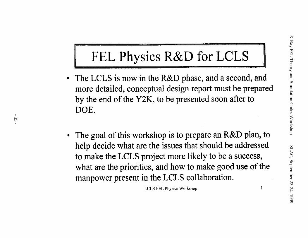
The LCLS is now in the initial R&D phase, and a second, more detailed, conceptualdesign report must be prepared by the end of the year 2000, to be presented soon after to DOE.The Workshop on FEL physics is being held to discuss the work needed to advance the LCLS toits next development stage, and will be followed by more workshops next year. The presentworkshop has the following goals:- Discuss what are the most important physics issues that should be addressed during the next
year.- Make the LCLS project more likely to be a success.- Establish priorities, and how to make good use of the manpower present in the LCLS
collaboration.- Organize an R&D plan.
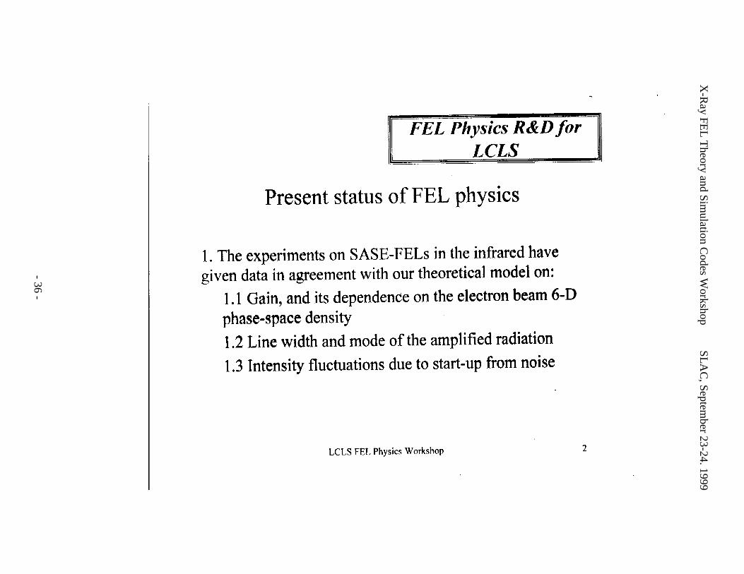
Present status of FEL physics
The experiments on SASE-FELs in the infrared have given data in agreement with ourtheoretical model on: gain, and its dependence on the electron beam 6-D phase-space density;line width and mode of the amplified radiation; intensity fluctuations due to start-up from noise.
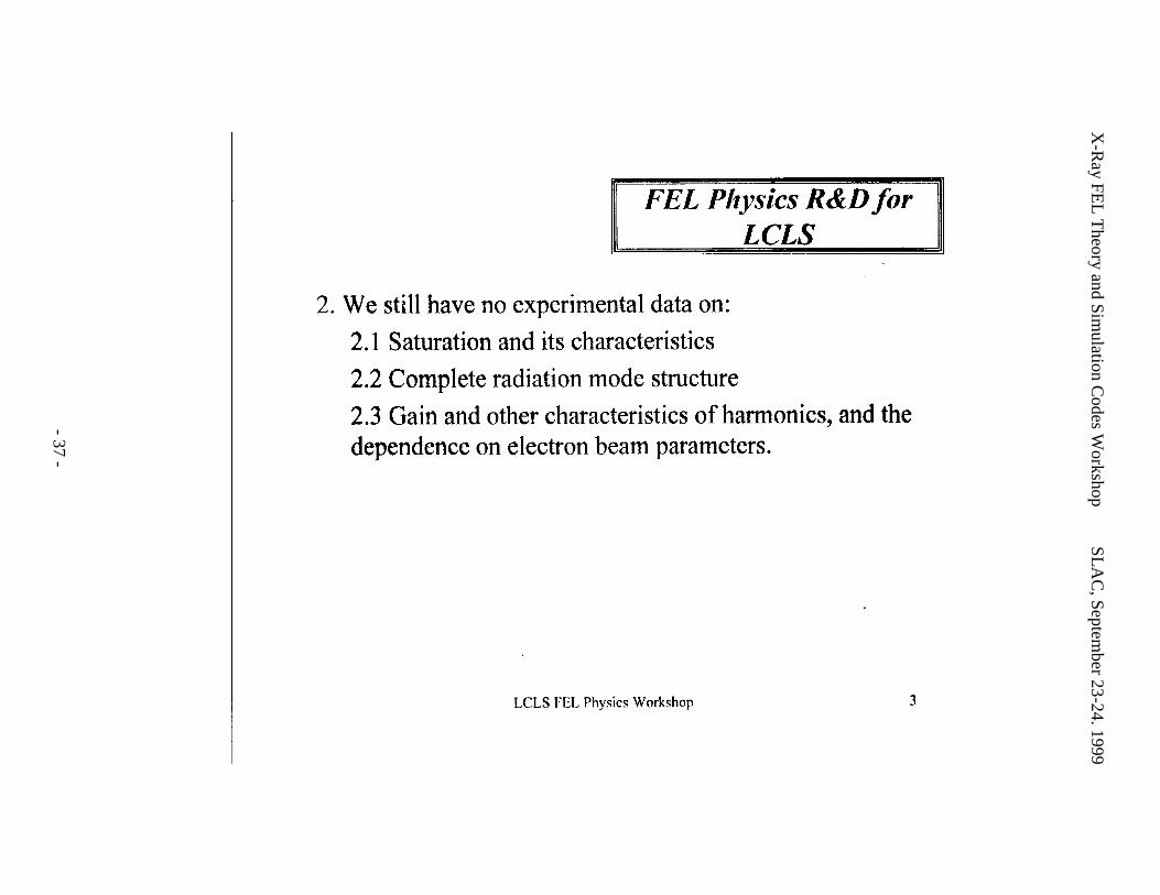
We still have no experimental data on:- Saturation and its characteristics.- Complete radiation mode structure.- Gain and other characteristics of harmonics, and their dependence on electron
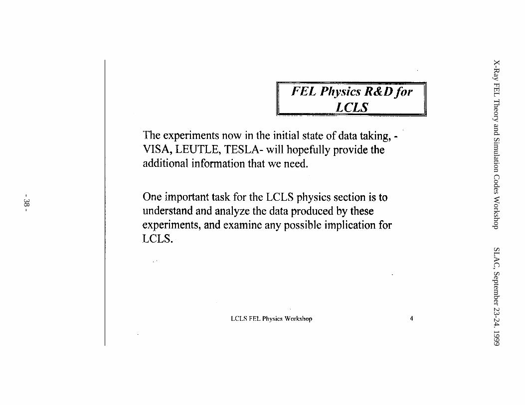
beam parameters.The experiments now in the initial state of data taking, VISA, LEUTL, TESLA, HGHG,
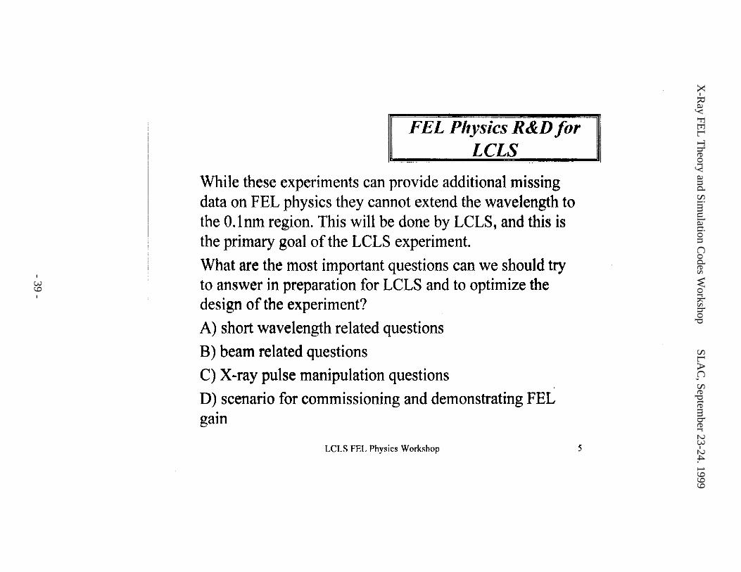
will hopefully provide the additional information that we need. One important task for the LCLSphysics section is to understand and analyze the data produced by these experiments, andexamine any possible implication for the LCLS. However, while these experiments can provideadditional missing data on FEL physics they cannot extend the wavelength to the 0.1 nm region.This will be done by the LCLS, itself. What are the most important questions we should try toanswer in preparation for the LCLS and to optimize the design of the experiment? They can bedivided in four areas:
A) Short wavelength related questions B) Beam related questions C) X-ray pulse manipulation questions D) Scenarios for commissioning and demonstrating FEL gain.
X-Ray FEL Theory and Simulation Codes Workshop SLAC, September 23-24. 1999
- 14 -
In what follows we will make a list of possible questions to be answered for each one ofthese four areas, with some short comments on initial results from the workshop.
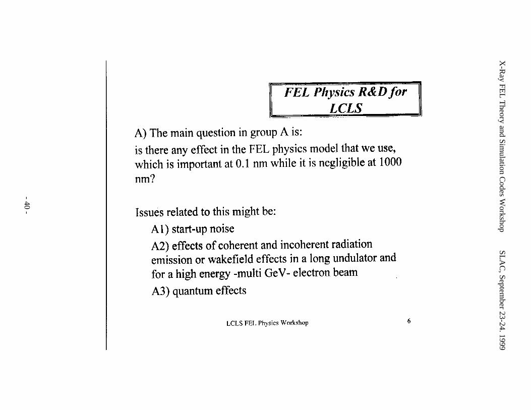
Short wavelength related questions
The key question in this group can be asked as: is there any effect in the FEL physicsmodel that we use, which is important at 0.1 nm while it is negligible at 1000 nm? Issues relatedto this might be: start-up noise; effects of coherent and incoherent radiation emission in theundulator or wakefield effects in a long undulator and for a high energy, multi-GeV, electronbeam; quantum effects.
This question was discussed at the workshop, and the main conclusion reached is that tothe best of our present knowledge there is no effect that will prevent the LCLS to operate aspredicted by our theoretical models. Quantum effects should be negligible for the LCLS beamparameters. Long wavelength coherent radiation and wakefields will however continue to bestudied in order to control any possible effect on the beam six-dimensional phase-space, whichmight influence the FEL gain.
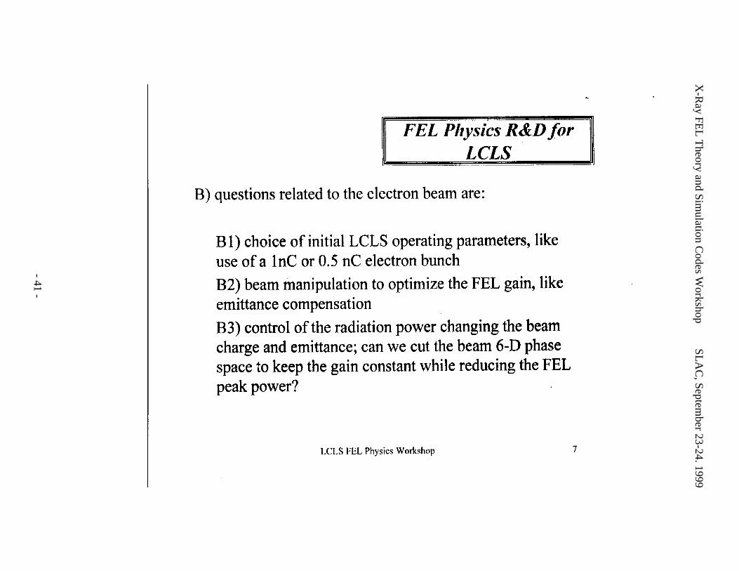
Questions related to the electron beam
Examples of these are,- choice of initial LCLS operating parameters, like use of a 1nC or 0.5 nC electron
bunch charge;- beam manipulation to optimize the FEL gain, like emittance compensation
schemes, or like low emittance, low charge operation to reduce wakefield effects;- control of the peak power of the X-ray pulse by changing the beam charge and
emittance.The last question can also be reformulated to see if there is a way to cut the beam 6-D
phase space keeping the FEL gain constant while reducing the FEL peak power.Much work can be done in this area to continue to optimize the LCLS, and extend the
range of operating parameters beyond that of the original LCLS design report.
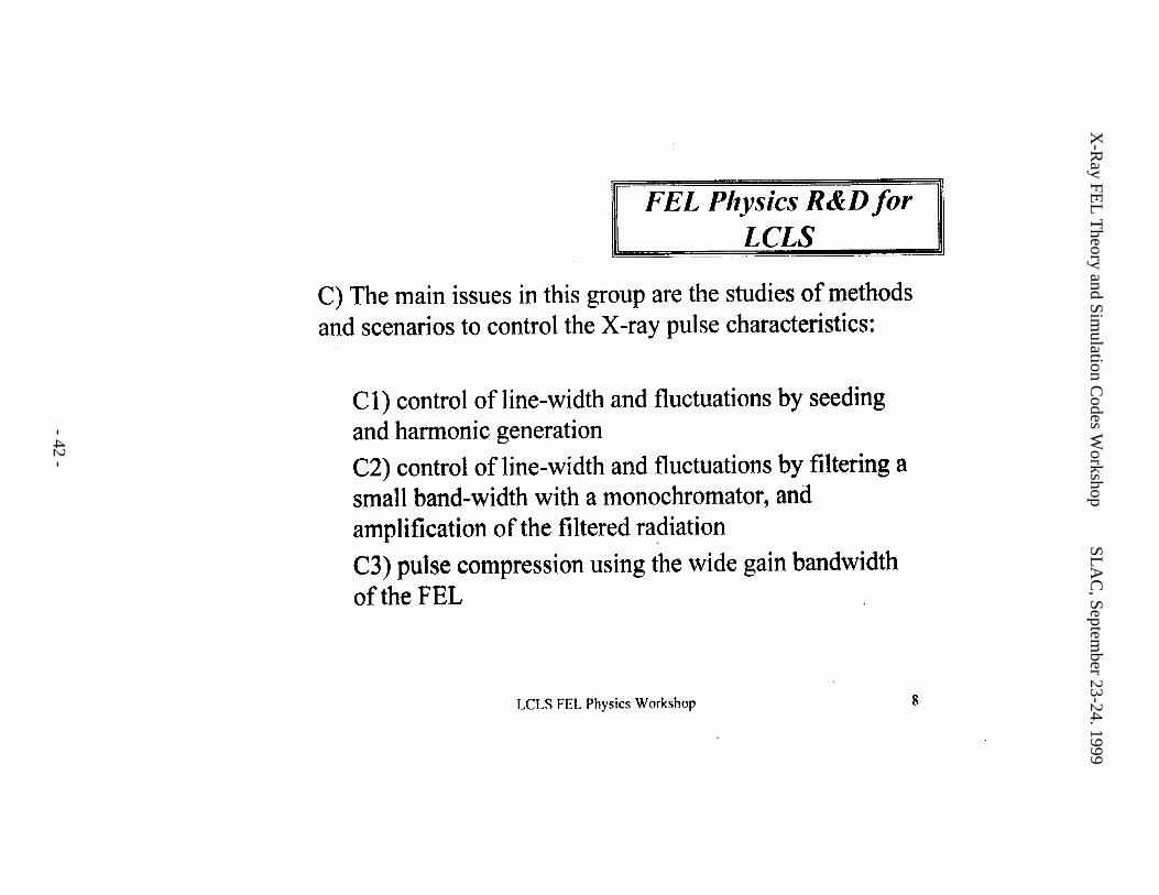
Methods and scenarios to control the X-ray pulse characteristics
The main issues in this group are the studies of methods to manipulate the LCLS X-raypulse to optimize its characteristics from the point of the view of the particular experiment one isdoing with the X-ray pulses. It is important to point out that the LCLS is a flexible system, andwe should be able to control its output pulse characteristics, similarly to what is done with visiblelasers. From this point of view some of the issues are:
- control of line-width and fluctuations by seeding and harmonic generation;- control of line-width and fluctuations by filtering a small band-width with a
monochromator, and amplification of the filtered radiation;- pulse compression using the wide gain bandwidth of the FEL.
X-Ray FEL Theory and Simulation Codes Workshop SLAC, September 23-24. 1999
- 15 -
Much work is needed in all these areas to develop practical schemes to manipulate the X-ray pulse.
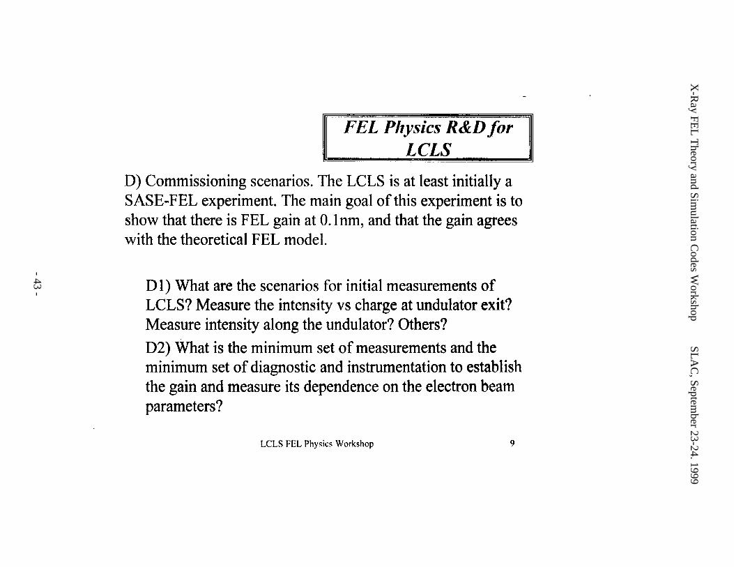
Commissioning scenarios
The LCLS is, at least initially, a SASE-FEL experiment. The main goal of thisexperiment is to show that there is FEL gain at 0.15 nm, and that the gain agrees with thetheoretical FEL model. It is important to prepare to achieve this goal in the shortest possibletime, so that we can then proceed to the other stages of the LCLS. Some of the questionsrelevant to this end are:
What are the scenarios for initial measurements of LCLS radiation characteristics?Measurement of intensity vs. charge at undulator exit? Measurement of intensity along theundulator? Others?
What is the minimum set of measurements and the minimum set of diagnostic andinstrumentation necessary to establish the gain and measure its dependence on the electron beamparameters?
What is the required level of beam control in photoinjector and linac, and what is therequired level of the instrumentation needed to reduce the intensity fluctuation to the valuedetermined by the initial start-up noise? If this reduction of the intensity fluctuation is notpossible can we use pulse selection techniques to reduce the fluctuation level? How do we do it?Although some initial work has been done, much more detailed work is needed to prepare forcommissioning of the LCLS.
X-Ray FEL Theory and Simulation Codes Workshop SLAC, September 23-24. 1999
- 16 -
III. SASE Fluctuation, Quantum Corrections and Undulator ErrorsBy Kwang-Je Kim
SASE Fluctuation
Statistical properties of SASE light are completely determined from the fact that theamplitude ωE is proportional to the sum of a large numbers of random phase factors. Light withthese properties, such as the sunlight or the spontaneous undulator radiation, is referred to as“chaotic”. The topic has been extensively discussed, for example by Goodman [1]. In thecontext of SASE it was thoroughly discussed by Saldin, Schneidmiller, and Yurkov [2]. Asimple review can be found in reference [3]. The probability distribution of the field amplitude,
ωE , of a chaotic light is Gaussian, as a straightforward application of the central limit theorem.Equivalently, the intensity at a given frequency =ωI | ωE |2 has an exponential probabilitydistribution in which the variance is equal to the average intensity. The fluctuation is therefore100%. In general, we consider a partial flux W∆ as the flux within a phase space volume ∆Ω .The probability distribution of W∆ is given by the “gamma” probability distribution [1]. In thegamma distribution, the fluctuation is reduced by a factor M , where the mode number M isthe number of coherent modes in ∆Ω . We can write LT MMM = , where TM and LM are,respectively, the transverse and the longitudinal mode numbers. For an electron beam of lengthcT generating a radiation pulse of bandwidth ω∆ , the longitudinal mode number is given by
ω∆= TM L .We can now compare the fluctuation in SASE from the LCLS and in undulator radiation
from typical third generation light sources at X-ray wavelengths. For the former, 1=TM (fulltransverse coherence), ρωω ≈∆ , 310−≈ρ , T is about 100 fs, while for the latter 1>>TM ,
ωω 01.0≈∆ , and T is about 100 ps. Therefore the fluctuation in SASE is larger by at least twoorders of magnitudes than that in the undulator radiation.
Quantum Effects
There are several quantum corrections to the SASE properties. However, these effects areall negligible in the case of X-ray SASE as discussed below:
First, the quantum correction to the classical gain formula is small if the recoil energy issmall compared to the gain bandwidth, or the photon energy is smaller than the electron energyspread. This condition is well satisfied for the X-ray SASE parameters.
Second, the effective noise signal needs to be modified when more than one electronoccupies the quantum mechanical unit cell of volume, 3)( C , were C is the electron’s Comptonwavelength. This is far from the case in the X-ray SASE.
Third, the mode number, M , becomes, after taking the quantum effect into account,)/11/( δ+M , where δ , known as the degeneracy number, is the number of photons per mode.
This correction is also negligible in the X-ray SASE since 1>>δ .
X-Ray FEL Theory and Simulation Codes Workshop SLAC, September 23-24. 1999
- 17 -
Undulator Errors
The errors in undulator magnets are most conveniently characterized by the phase error.For a long undulator such as needed by a SASE FEL, the errors could be controlled by steeringcorrections at regular intervals. In this case, the errors in the derivative of the phase with respectto the distance along the undulator can be regarded as uniformly distributed along the undulator.The degrading effect of the undulator errors on SASE performance was most completelyanalyzed for this type of error [4], which may be referred to as the random kick error (RKE).However, there could be another type of error. Indeed, for well-optimized undulators, correctedby suitably placed shims, the phase error itself rather than its derivative should be regarded asdistributed uniformly along the undulator. This type of error may be referred to as the randomphase error (RPE). Effects of the RKE and RPE on the performance of spontaneous emissionand high-gain FEL have been studied in reference [5]
References
[1] J. Goodman, “Statistical Optics” (John Wiley & Sons, New` York, 1985).
[2] E.L. Saldin, E.A. Schneidmiller, and M.V. Yurkov, DESY preprint TESLA-FEL97-02(April 1997)
[3] K.-J. Kim, in Proceedings of the Workshop on Single Pass High Gain FELs from Noise,Aiming at Coherent X-rays, Lake Garda, Italy, June 2-7, 1997.
[4] L.H. Yu, S.Krinsky, R.Gluckstern, van Zeijt, Phys. Rev. A45 (1992) 1163.
[5] K.-J. Kim, 1999 FEL conference
IV. High-Gain, Higher-Harmonic TheoryBy Li Hua Yu
Recent results from the High Gain Harmonic Generation (HGHG) experiment at BNLshow that it is possible to use longer wavelength laser light as a subharmonic seed for an FEL toachieve saturation by exponential growth at shorter wavelength. The output radiation fromHGHG is very stable and has Fourier-transform-limited bandwidth. The experiment agrees withthe theory.
A theoretical study recently showed that the HGHG process can be cascaded by severalstages starting from 288-Angstroms radiation (available from conventional laser sources) toreach 1.5 Å. Preliminary simulations showed that to achieve the same output power as the LCLS(10 GW) the required total length of the undulators including those for longer wavelengths is thesame as the total undulator length (about 100 m) for the LCLS using the same set of electronbeam parameters.
X-Ray FEL Theory and Simulation Codes Workshop SLAC, September 23-24. 1999
- 18 -
The parameters used in this calculation are not optimized, so far. With optimization, it isexpected that the total undulator length can be reduced. In particular, the undulator section forthe 1.5-Angstrom radiation is already shorter than half the total length of the present design whenusing the present parameters without optimization. This may help reduce the effect due to thesurface roughness of the vacuum chamber wall since the undulator sections for longerwavelengths have larger periods and hence can use larger undulator gaps.
This cascading HGHG scheme needs five electron bunches, and hence a study aboutdifferent methods to generate e-beams with several bunches is needed in the future. During thegroup discussion it was also suggested to study the parameter sensitivity of the systemperformances to synchronization errors and other beam parameters. It was also suggested tostudy the transition between different stages of the HGHG cascade, for example the opticaltransport between stages.
V. Status of the 3D FEL TheoryBy Ming Xie
There are three major developments that have made linac-based, single pass FELs theapproach of choice to reach short wavelength:
- first, technological advances in the generation, acceleration and preservation of highbrightness electron beams,
- second, theoretical advances in the understanding of high gain FEL physics, leadingto confident prediction, optimization, and scaling of FEL system performance to shortwavelength, and
- third, an enthusiastic support from the light source user community. Of thetheoretical advances the most significant and impressive achievement is thedevelopment of high gain 3D FEL theory over the past fifteen years.
There are two milestone achievements in the development of 3D FEL theory, which havelaid the theoretical foundation for a great leap forward toward short wavelength. The first one isthe discovery in 1984 and subsequent elucidation of optical guiding. With optical guiding, thediffraction problem is solved, thus FEL amplification can be extended indefinitely in a longwiggler to reach power saturation in a single pass. The next question is, of course, how long awiggler does it take for this to happen? In other words, how does the FEL growth rate depend onelectron beam and other system parameters? Furthermore, how does this dependence scale toshort wavelengths? To answer these questions, the most important and difficult task is theunderstanding of the effects of emittance and associated betatron focusing. The solutions to thisproblem therefore constitute the second milestone achievement in 3D FEL theory. Today, thestate-of-the-art analytical 3D theory has reached such a sophisticated stage that in several crucialaspects of physics it can simultaneously treat the effects due to energy spread, emittance andbetatron focusing of electron beams, as well as diffraction and optical guiding of the laser fieldwith high accuracy. Yet, there is still a lot to be desired of this theory and its full potential is far
X-Ray FEL Theory and Simulation Codes Workshop SLAC, September 23-24. 1999
- 19 -
from being reached. Solutions to a number of important problems can be expected in the nearfuture.
The main objective of the 3D FEL theory is the determination of initiation, growth,saturation, and coherence characteristics of the laser field, as well as the evolution of the electronbeam associated in the process. In the case of single pass FELs, it is fortunate that most of thesetasks can be carried out in the framework of linear theory, therefore through analytical approach.In a nutshell, the 3D theory is about the solutions of two problems: the eigenvalue problem andthe initial value problem.
The solution to the eigenvalue problem has been the most successful part in 3D FELtheory, in terms of both, an efficient numerical technique for the exact solution and an effectivemethod for an approximate solution. Based on these solutions, growth rate and mode propertiesof the laser field can be calculated with high accuracy. The solution has been mapped out in theentire parameter space and interpolated into simple formulas to facilitate system design andoptimization. In addition, the solution to higher order FEL eigenmodes has lead to a quantitativeanalysis of transverse coherence of SASE. Of the two models considered for electron beamdistribution in transverse phase space: waterbag and Gaussian, only an approximate solution isavailable for the former.
On the other hand, the initial value problem has been solved only in the case of a parallelelectron beam without angular spread. Thus the effects of emittance and betatron focusing arenot included in the solution. As a result, our predictions of SASE noise power, saturation length,and degree of transverse coherence of SASE are less accurate. The initial value problem,including effects of emittance and betatron focusing, is one of the most important outstandingissues.
Most of the 3D solutions obtained so far assume constant gradient for betatron focusing.One extension is available to model alternating gradient focusing, however, the model is validunder restricted conditions of a smooth approximation. In order to study the effects of beamenvelope modulations due to alternating gradient focusing, the theory has to be further extended.
Harmonic generation in the high gain regime is an attractive and promising approach toreach short wavelengths. To further distinguish between different types of harmonic generation,let’s introduce some new terminology: parasitic harmonic generation and cascade harmonicgeneration. Parasitic harmonic generation, by definition, exists in all FELs under allcircumstances. A 3D analysis is available for this process. It would be interesting to know if thepower in the harmonics could be optimized and how. Cascade harmonic generation, known ashigh gain harmonic generation (HGHG), is a very important alternative approach to SASE inreaching short wavelength. The analytical theory on this process is essentially 1D. An importantissue of this approach is the possibility of scaling the scheme to very high harmonics in order toreach hard X-rays. Due to the involvement of multiple wigglers of quite different specificationsand the large possibility in the variation of the scheme, a 3D analytical theory is a necessarycomplement to simulation for a system optimization.
The analysis on wiggler errors still remains 1D. This 1D analysis is expected to bereasonably good if the optical mode size is much larger than the electron beam size. However,for the LCLS case, the optical mode size is slightly smaller than the beam size.
X-Ray FEL Theory and Simulation Codes Workshop SLAC, September 23-24. 1999
- 20 -
Finally, the radiation field profile from the SASE process, although determinedcompletely before saturation by the linear theory, can be modified by the nonlinear process atsaturation. It is important to know about this effect, as it is the modified field that is delivered tothe users through the X-ray optics beamline. Also, our estimation of saturation power is stillbased on either a simple model or an empirical formula, and its region of validity has not beenextensively tested. Improvement might be possible by employing either a quasi-linear theory ora scaling law in the nonlinear regime, coupled with simulation
VI. 3D Nonlinear HarmonicsBy Zhirong Huang
In a high-gain FEL based on a planar wiggler, strong bunching at the fundamentalwavelength can drive substantial harmonic bunching and sizable power levels at the first few oddharmonic frequencies. Unlike a subharmonically seeded high-gain harmonic generation(HGHG) FEL [1] that employs two wigglers with the second wiggler resonant to one of theharmonics of the first and a dispersion section between the wigglers to maximize the spatialbunching at the fundamental of the second wiggler, this nonlinear harmonic generation occursnaturally in one long planar wiggler for a SASE FEL with an initially uniform bunch, as well asfor the second stage of an HGHG FEL using a density-modulated bunch. Thus, such a naturalharmonics generation mechanism may be utilized to reach shorter radiation wavelengths or torelax some stringent requirements on the electron beam quality for x-ray free-electron lasers.
A three-dimensional theory of the nonlinear harmonic generation is presented [2] in thisworkshop, using the coupled Maxwell-Vlasov equations that include the effects due to energyspread, emittance, and betatron focusing of the electron beams, as well as the diffraction andoptical guiding of the radiation field. Each harmonic field is the sum of a self-amplified termand a term driven by nonlinear harmonic interactions. In the exponential gain regime, thegrowth rate of the dominant nonlinear term is much faster than that of the self-amplifiedharmonic field. As a result, the gain length, the bandwidth and the transverse profile of the firstfew harmonics are completely determined by those of the fundamental. For example, the thirdnonlinear harmonic grows three time faster than the fundamental, has a narrower gain bandwidth(by a factor of 1/sqrt3), is transversely coherent (with a smaller spot size), and has a powerlevel on the percentage of the fundamental with the current LEUTL FEL and LCLS designparameters.
During the workshop, several key issues regarding nonlinear harmonic generation arediscussed. The present theory has been compared with the 3D MEDUSA simulation code thattracks the nonlinear harmonic evolution up to the ninth harmonic [3]. Good agreement is foundon the power level of the third harmonic radiation using the LEUTL FEL parameters. However,the simulation indicates the beam sizes of all the harmonics diverge, while the theory predictsconstant beam sizes for these nonlinear harmonics generated by the transversely coherentfundamental radiation. It is emphasized that the nonlinear harmonic generation comes from thenon-sinusoidal electron trajectory in a planar wiggler (the figure-eight motion in the electron’sco-moving frame), not from the non-sinusoidal magnetic field distribution. It is also pointed out
X-Ray FEL Theory and Simulation Codes Workshop SLAC, September 23-24. 1999
- 21 -
that the higher harmonic radiation is more sensitive to magnetic field errors and gaps betweenseparate wiggler sections due to the phase decoherence. These effects have yet to be studied.
References
[1] L.H. Yu, Phys. Rev. A 44, 5178 (1989).
[2] Z. Huang, K.-J. Kim, Three-Dimensional Analysis of Harmonic Generation in Self AmplifiedSpontaneous Emission, to be published in the FEL99 proceedings, Hamburg, 1999.
[3] H. Freund et al., Nonlinear Harmonic Generation and Proposed Experimental Verification inSASE FELs, to be published in the FEL99 proceedings, Hamburg, 1999.
VII. Discussion
Throughout the workshop, the Theory Working Group was seeking to identify topics thatwere less mature and thus worthy of more attention. Most importantly, the group was lookingfor possible new effects that might jeopardize the LCLS project at 1 Å. Particularly treacherouswould be an effect that would be undetectable at longer wavelengths (e.g. 1 µm), but harmful atshort 1-Angstrom wavelengths. At the conclusion of the workshop, there was no such effectidentified.
Several theory topics that were considered to be relatively mature are - Classical and quantum start-up from noise, - Undulator error sensitivity, - Betatron function modulation, and - Undulator section separations.
Less mature theory topics that may require more attention are - Vacuum pipe impedance effects, see Kwang-Je Kim's talk below, - New schemes, see Li Hua Yu's talk, - Harmonics, see Zhirong Huang's talk, - Saturation, see Bill Colson below, and - Diagnostics, what to measure and how accurately, see Bill Colson below.
Other topics that for consideration were - The total radiation spectrum, - Coherent radiation beyond 1-Angstrom wavelength, - Improved temporal and spatial properties, and - Monochromatization.
X-Ray FEL Theory and Simulation Codes Workshop SLAC, September 23-24. 1999
- 22 -
VIII. Impedance EffectsBy Kwang-Je Kim
The total radiation intensity from an electron beam passing through an undulator consistsof the incoherent part proportional to the number of electrons, eN , and the coherent partproportional to 2
eN . The reaction of both of these parts on the electron beam could lead todegradation of the electron beam limiting the performance of SASE. Thus an obvious effect isthe reduction in electron beam energy (deceleration) which must be within the gain bandwidth.The effect of the incoherent part on the electron beam energy spread was analyzed by the DESYgroup. The effect of the coherent part (most of which is in the form of SASE radiation) isbasically an impedance effect, which was studied in old references (for example, by Y.H. Chin).This impedance may need another look, including a literature search.
The “normal” impedance effect due to the surface roughness of the narrow bore of thevacuum chamber was studied by G. Stupakov leading to a stringent specification of the surfaceroughness.
IX. Schemes for Improving the SASE Performances:By Kwang-Je Kim
Two-stage undulator for a narrow spectrum
The scheme was proposed by the DESY group as a promising way to achieve a spectralwidth much narrower than the natural SASE bandwidth ρωω ≈∆ / [1]. It consists of undulatorU1, a monochromator, and undulator U2. In U1, SASE grows well above the noise level in theexponential gain regime. The signal is spectrally filtered in the monochromator, and is amplifiedto the saturation in U2. In order to reduce the fluctuation, the length of U2 is chosen to besufficiently long so that it is operating well into the non-linear saturation regime. The scheme hasbeen analyzed within 1-D theory. However, 3-D effects could be important, as the transversemode profile in the saturation regime will be, in general, different from that in the exponentialgain regime.
Pulse compression
The length of a SASE pulse, τc , is normally determined by the electron beam, which isabout 100 fs. However, it consists of x-ray wavelets each about 1−ρ periods, where 310−≈ isthe FEL scaling parameter. Therefore it should be possible to compress the SASE pulse to alength Fmin ≈ , which is about 1 fs for =λ 1 Å [2]. The compression is accomplished byintroducing an energy slew in the electron beam leading to the frequency chirp (frequency shiftper unit length). The maximum chirp consistent with the FEL gain is given by
/ /c( 2max ==/ . The chirped pulse can then be compressed with a grating
pair. The minimum pulse length achievable is F c maxmin == . The technique forpulse compression has been extensively developed for high-power solid state lasers at visible
X-Ray FEL Theory and Simulation Codes Workshop SLAC, September 23-24. 1999
- 23 -
wavelengths. For the X-ray SASE pulse, a major research project will be to demonstrate that therequired optical elements exist.
Circular polarization
Recently, a crossed undulator configuration was proposed for a high-gain free electronlaser for versatile polarization control [3]. It consists of a long (saturation length) planarundulator, a dispersive section, and a short (a few gain lengths) planar undulator orientedperpendicular to the first one. In the first undulator, a radiation component linearly polarized inthe x-direction is amplified to saturation. In the second undulator, the x-polarized componentpropagates freely, while a new component polarized in the y-direction is generated and reachessaturation in a few gain lengths. By adjusting the strength of the dispersive section, the relativephase of two radiation components can be adjusted to obtain a suitable polarization, includingthe circular polarization, for the total radiation field. The operating principle of the high-gaincrossed undulator, which is quite different from that of the crossed undulator for spontaneousradiation, was studied in 1-D FEL theory in the exponential gain regime. However, the analysisdid not take the fluctuation effect into account, which will be important especially nearsaturation.
References
[1] J. Feldhaus, E.L. Saldin, J.R Schneider, E.A. Schneidmiller, M.V. Yurkov, DESY preprintTESLA-FEL 96-10
[2] C. Pellegrini
[3] K.-J. Kim
X. LCLS Saturation TheoryBy Bill Colson
Almost all of the hundreds of FELs that have been operated over the last 20 years havereached saturation in strong optical fields. In the high gain regime, the LLNL ELF experimentsreached saturation many years ago and the results are well understood. But ELF operated at 1-cm wavelength and the radiation mode was confined to a waveguide with an electron beam thatwas smaller than the cross-section of the radiation mode. The LCLS FEL is expected to havehigh gain comparable to ELF, but the X-ray radiation mode is freely propagating without awaveguide.
It can be expected that the one-dimensional aspects of saturation without diffraction canbe determined by the same theory and simulation codes that successfully described ELF. These
X-Ray FEL Theory and Simulation Codes Workshop SLAC, September 23-24. 1999
- 24 -
simulations and theories predict fluctuations in the LCLS X-ray radiation field before and aftersaturation. The radiation fluctuations at saturation were not measured in detail for ELF.
Current high-gain SASE experiments will provide a better confirmation of ourunderstanding of fluctuations at saturation. Since the X-ray radiation spectrum is an importantaspect of the LCLS, an improved understanding of saturation should be directed towardsdeveloping techniques or modes of operation to reduce fluctuations at saturation.
The three-dimensional aspects of LCLS saturation are more likely to lead to new effectsnot observed in ELF or any other FEL experiment. The shot noise from the tenuous electronbeam at the out edges of the x-ray radiation mode is a new feature that may alter fluctuationresults. It was felt that there are opportunities for new theory research in this area.
XI. LCLS DiagnosticsBy Bill Colson
An important contribution from theory will be to make a statement about what should bemeasured in the LCLS experiment and how accurately it should be measured. This contributionis not to be made here, but the workshop theory group acknowledges that this is an area forfurther work.
One result of the diagnostic study will be the finding that many variables affect thegrowth rate and coherence of the X-ray beam. The most significant effects from the six-dimensional electron beam phase-space can be summarized by converting their contributions tothe electron phase velocity, or z-velocity distribution function. There was extensive use of thisreduced distribution function during the development and analysis of the LLNL ELF FELexperiments. Coupling between the electron beam and X-ray radiation is primarily determinedby the electron phase distribution within each x-ray wavelength. It is the electron phase velocitydistribution that determines the electron phase distribution during the interaction along the 100-mundulator length. It is therefore recommended that the electron beam’s phase velocity distributionbe used as a method of summarizing the parametric effects of the many variables that caninfluence LCLS performance.
X-Ray FEL Theory and Simulation Codes Workshop SLAC, September 23-24. 1999
- 25 -
SUMMARY OF WORKING GROUP II
Code Status, Development Plans and Options
Working Group Members:
Sandra Biedron (ANL), Michael Borland (ANL), Roger Dejus (ANL),Paul Emma (SLAC), William Fawley (BNL), Henry Freund (SAIC),Massimo Ferrario (INFN-LNF), John Goldstein (LANL), Heinz-Dieter Nuhn (SLAC),Claudio Parazzoli (Boeing), Roman Tatchyn (SLAC), Richard Binonta (LLNL)
I. IntroductionWorking Group II was comprised of approximately one dozen individuals who met for
approximately six hours spread over 1-1/2 days to discuss simulation code issues relevant toXUV and X-ray SASE FELs. In order to make efficient use of our very limited time, we hadagreed before meeting upon a format of several different topic areas together with one or moreindividuals tasked to make a short status presentation in each area. In order of discussiontogether with their respective presenters, these areas were (a) Undulator modeling and transportissues (H. Freund) (b) Harmonics (S. Biedron) (c) Code communication and interface issues(M. Borland) (d) Radiation transport beyond the undulator (R. Bionta). We also discussedissues such as inclusion of additional physics (e.g. wake fields) and numerical accuracyrequirements (e.g. particle statistics) in SASE-relevant simulation codes.
This report summarizes our findings and conclusions, if any, in each of these variousareas together with indications of where the group felt additional work should be applied overthe next 12-18 months. This short time scale is dictated by the present schedule of the LCLSproject which plans to present a design proposal to DOE by late spring 2001 for whichsimulation information will be needed by December 2000. Appendix A gives an extendedsynopsis of a number of FEL codes presently in use for modeling short wavelength SASE FEL’s.All in all, the working group felt we had a productive session, especially given the shortavailable time and the persistent (but humorous) interruptions by the SLAC aerobics Mafia.
II. Undulator modeling and beam transport issuesAll of the proposed XUV and shorter wavelength SASE FEL devices employ undulators
with hundreds-to-thousands of wiggler periods. These great lengths together with the relativelylow gain of these devices dictate that the undulator must be of high quality (i.e. good fieldquality and alignment) and similarly that the code transport models and algorithms must also beof high accuracy.
Much of the discussion in this area centered upon the issue of whether any importantphysics is being missed by adoption of the wiggler-averaged (KMR) FEL interaction equations.With the exception of the MEDUSA code, nearly all simulation codes in the SASE area employ
X-Ray FEL Theory and Simulation Codes Workshop SLAC, September 23-24. 1999
- 26 -
wiggler-averaging. Although the KMR formulation has significant advantages due to itssimplicity, it requires assumptions in areas such as radiation emission in the first few wigglerperiods following a drift and the coupling to higher harmonics (i.e. the [JJ] term). A non-wiggleraveraging algorithm, in theory at least, can treat the "exact", imperfect wiggler field at each pointin space. However, it intrinsically requires longitudinal step sizes that are much smaller than awiggler period whereas other longitudinal scale lengths (e.g. radiation gain length, Rayleighrange, synchrotron oscillation wavelength) might be much larger than a period and for which thewiggler averaging approach might be far more efficient computationally. There also remain(among certain workers in the FEL simulation field) some questions of self-consistency in thedecomposition of the local source terms between those, which couple to the radiation "far field"and those, which might be evanescent and/or propagating at large angles compared to 1/γ. Thisissue is probably of most concern at much lower energies than the LCLS and it would besurprising if the two approaches gave significantly different results. Hence, the working groupfelt it would be highly useful for MEDUSA’s author (H. Freund) to implement a wiggler-averaging option in order to permit examination of what prediction differences (e.g. outputpower) would arise between the two formulations in the context of LCLS- and LEUTL-likeparameters.
Another area of discussion concerned magnetic field models and the implementation ofexternal focusing and wiggler errors into simulation codes. Many codes have the ability to readin tables of wiggler errors; MEDUSA can read in a detailed 3D field map (which even for 100-mlong wigglers as in the case of the LCLS only requires a couple of minutes or less on aworkstation). H. Freund mentioned that R. Jackson, while at NRL in the 1980’s, put together acomputational package to determine higher order off-axis derivatives of the wiggler fields, whichmight be of use to those who want to include such terms in their particle movers. Given thepresence of external quadrupoles and the existence of periodic drift sections (which are normallyused for diagnostic access) in both the LEUTL and proposed LCLS wiggler lattices, WorkingGroup II believed it was important that all of the simulation codes be able to treat both types ofelements.
Wiggler "errors" come in a variety of forms. The most important are probably amplitudeerrors in pole-to-pole excitation which, in general, will lead to transverse kicks and offsets. Thistype of error can also lead to a longitudinal phase error in the coupling between the radiation andthe electron beam. Another type of detuning error exists when the average of aw (averagedlocally over one or more periods) deviates by an amount on the order of ρ from the wantedvalue. However, for all but the shortest wavelength/low gain FEL’s, this detuning is normally notimportant. Most of the existing "3D" codes, e.g. FELEX, MEDUSA, GENESIS; and some 2Dones such as RON already include the transverse kicks due to wiggler errors and can also modelsteering corrections by appropriately placed dipoles. The details of wiggler error treatmentundoubtedly vary from one code to the next. Therefore, R. Dejus of ANL offered to make freelyavailable in a standard format such as SDDS the results of detailed measurements of the first fiveLEUTL undulator sections (and proposed dipole steering corrections) for each author to use intheir respective code in order to determine effects upon the predicted LEUTL performance.During a joint meeting with the FEL Theory working group, a short talk by L.-H. Yu (BNL)suggested that wiggler errors would in general more seriously degrade power at higher
X-Ray FEL Theory and Simulation Codes Workshop SLAC, September 23-24. 1999
- 27 -
harmonics. This prediction could be studied with some of the existing simulation codes (see Sec.III).
There was a group consensus that further wiggler error tolerance studies needed to bemade for the LCLS. Probably the great majority of this study can be done with a monochromaticformulation. Paul Emma (SLAC) suggested a need for a quick running code, which couldexamine the efficacy of different optimization strategies for electron beam trajectory control.Many of the existing codes have the ability to run a "reduced" problem in which the electronbeam evolves independent of any background radiation field. It may also be useful for two ormore of the codes to be able to accept a trajectory control (i.e. steering magnet setting)algorithm "module" from the "outside". To some extent, such module interchangeability fallswithin the code "interface" issues discussed in section IV.
III. HarmonicsIt is well known that there will be extensive radiation at odd harmonics of the
fundamental for SASE FELs with linearly polarized wigglers. S. Biedron presented predictionsby the MEDUSA code for the output power and coherent spontaneous "gain" lengths ofharmonics in LEUTL and in the High-Gain Harmonic Generation (HGHG) experiment at BNL.Despite the quite short gain lengths (which are a factor of n shorter for the nth harmonic than thefundamental), the power in each harmonic remains relatively small until within a couple gainlengths of fundamental saturation. The HGHG experiment will test many of these principles, inaddition to investigating the 2nd harmonic bunching performance of an optical klystron sectionfor a high gain, single-pass amplifier.
During the discussion of Working Group II, there was interest in using 3rd and 5th
harmonic power as a diagnostic of beam and wiggler quality. More analytical and simulationwork on the sensitivity could be useful. For example, the effects of "real" wiggler errors (asdetermined by wiggler field mapping) upon the predicted growth rates of harmonics should beexamined. The question of differences between wiggler- and non-wiggler-averaged codes aroseagain and it was suggested that harmonics be included in the comparison studies suggested inSection II. The LEUTL experiment at ANL could be a very useful test bed in the area ofharmonic growth from noise. Unfortunately, the short fundamental wavelength λ=532 nmtogether with the open-air transport from the wiggler exit to the diagnostic station will causesevere absorption losses at the 3rd and higher harmonics. It may be possible for LEUTL to "backoff" sufficiently in wavelength (e.g. by increasing aw or decreasing Ebeam) so that the 3rd
harmonic enters the blue region of the spectrum.
IV. Code Interface and CommunicationM. Borland (ANL) discussed the advantages of and the need for one (or possibly two)
standard data formats with which FEL and accelerator (e.g. tracking) codes could exchange data.One distinct advantage of using an externally defined format is that it frees individual codes frombeing "locked" to each other. One such format, the Self-Describing Data Set (SDDS), is in wideuse at ANL and some other DOE accelerator labs. In addition to providing I/O capabilities, theSDDS package also has some analysis and scientific visualization features, which have proven
X-Ray FEL Theory and Simulation Codes Workshop SLAC, September 23-24. 1999
- 28 -
quite useful for various tasks such as parameter sensitivity studies. As an alternative toembedding the SDDS or other format package in a given FEL or accelerator code, Borlandsuggested a different approach of writing simple adapter programs to "repackage" the output.Such was done with the GINGER code at ANL a couple years ago. This approach may also bedesirable for simulation codes written in Fortran because the SDDS package is heavily orientedtoward C/C++ routines at present. The ANL group has offered to write such adapter programsfor individual codes so long as a sufficiently clear specification is provided. The working groupquickly agreed that the SDDS format should be adopted by as many FEL codes as possible toassist with exchange of data both to other FEL codes and to outside codes.
A related issue to code interfacing is that of "start-to-end" modeling of FEL performance.C. Parazzoli (Boeing) presented some of the studies he has done with the FELEX code toexamine output power sensitivities to input particle distributions provided by the PARMELA-TRACE3D package. In many cases, realistic distributions gave quite different results fromsimple Gaussian distributions and he stressed that similar interfacing would probably be neededfor the LCLS. One issue that arose during the discussion of interfacing tracking codes to FELcodes was the great temporal "mismatch" between the FEL codes and tracking codes. FEL codestypically use thousands of macro-particles per sub-femtosecond slice, as compared with mosttracking codes, which typically use a couple of thousand or fewer macroparticles to model theentire picosecond duration of the electron beam pulse. It may be necessary to modify one ormore of the tracking codes to make them capable of providing a greater sampling density of 6Dphase space in discrete sections of the pulse and/or both formulate and write a clever algorithmto interpolate from the sparsely populated tracking results to the required high density needed bypolychromatic FEL codes.
V. Radiation Transport beyond the UndulatorR. Bionta discussed some aspects of the LLNL group’s work on modeling transport of the
FEL radiation pulse after the wiggler and the development of detectors for beam diagnostics aswell as the optical components for transport. One important area is plasma formation andhydrodynamic phenomena associated with the interaction of the intense EM pulse with theattenuator, bending mirrors, crystals, diffraction gratings and sensors placed in the beam.Successful development of diagnostics and optical components requires reasonable models ofboth the FEL beam and the spontaneous radiation emissions. These models must cover thesignificant FEL harmonics and electron beam energies (especially if the 3rd harmonic will beused at reduced beam energy.)
At present, it is believed that valid preliminary assessments of LCLS radiation-matterinteractions can be started with the simplified descriptions of the LCLS radiation given in theLCLS Design Study Report supplemented with further 3D FEL simulation runs. For the purposesof designing sensors and optics, the FEL beam will be modeled using Gaussian wave packets inspace and time for each micropulse. In addition to a central frequency, the Gaussian wave packethas essentially 4 other parameters: transverse beam size, w; phase curvature, R; peak amplitude,A; and micropulse duration, τ. The central frequency of the fundamental and all other modes canbe obtained at all values of beam energy from the well-known formula in the LCLS DesignStudy Report. The transverse beam size, w, and phase curvature, R, are also given explicitly in

X-Ray FEL Theory and Simulation Codes Workshop SLAC, September 23-24. 1999
- 29 -
the report for the minimum and maximum beam energies and can be found at other beamenergies and other modes by a linear interpolation.
Values for the peak amplitude, A, and micropulse duration, τ, are more difficult to obtain.The Design Study Report gives data and formulae for calculating the saturated power of the FELfundamental at all beam energies. To convert saturated power to peak amplitude requiresknowledge of the number and duration of the micropulses, as well as statistics on the distributionof energy amongst the micropulses. A simplifying assumption, good for many of the situationsunder consideration, is to model the micropulses as a series of wave packets with equal durationat a given repetition rate with the energy divided equally among the packets. With thisassumption, the amplitude of the wave packets can be calculated from the saturated power, therepetition rate, and the duration. H. -D. Nuhn has produced a 12-fs simulation showing the timestructure of the FEL fundamental at full beam energy from which the average pulse duration andrepetition rate can be measured as well as some limited statistics on the individual micropulseintensities.
The radiation time structure at other beam energies is not yet available. It can probably becrudely estimated from H.-D. Nuhn’s result through some sort of scaling of the slippage andcooperation lengths at different energies. Since the LCLS could start up at lower than maximumbeam energies, it is important to clarify the time structures at all beam energies and have explicitsimulations at the energy chosen for start up.
Finally the power levels of the higher harmonics are not given in the LCLS Design StudyReport. Since there is interest in utilizing higher harmonics in initial operations of the LCLS atlower beam energies, it is important to model (either theoretically or numerically) the expectedintensities.
It is anticipated that more refined studies, as well as certain classes of LCLS experiments(e.g., single-shot imaging and diffraction) would benefit from a detailed knowledge of the photondistributions along each of the phase space dimensions associated with the individual slippageregions of the bunch. A similar level of simulational accuracy would also benefit the design ofoptical instrumentation for characterizing the lasing performance of the LCLS, as well as fortransporting the radiation to experiments. A desirable goal would be to relate the requireddescriptions of the radiation to the specific phase space structure of a single electron bunch, fromwhich bunch-to-bunch variations in the photon phase space distributions could be deduced. Ingeneral, while the nominal goal of the LCLS diagnostics is to characterize each of thesedistributions - either statistically or on a single shot basis - it is anticipated that direct temporalprofiling of the radiation’s longitudinal structure will be the most difficult to achieve. Suchinformation would be of particular interest during the commissioning phase to help determinewhich portions of the electron beam pulse are lasing and which are not. In this regard, maximallyrealistic and accurate 3D simulations could be critical in assessing or developing techniques toperform such a measurement.
VI. Numerical Issues and Need for Additional PhysicsWorking Group II had a brief interchange concerning the numerical/statistical accuracies
of the various FEL codes represented in the group. In general we agreed that 1000-4000macroparticles/slice give good results, with the larger number needed when there is a significant
X-Ray FEL Theory and Simulation Codes Workshop SLAC, September 23-24. 1999
- 30 -
instantaneous energy spread. For fully gridded 3D codes, Cartesian geometries normally requiremore than 64×64 zones as compared with 32–64 radial zones for 2D codes. For an r-θ code suchas FRED3D, 2–4 azimuthal zones per radial zone are sufficient for most problems. For a codesuch as MEDUSA, which uses a Gauss-Hermite spatial mode decomposition, 3–24 independentmodes are normally adequate. In time-dependent (polychromatic) simulations, ~128 temporalslices give appropriate resolutions for LCLS-type problems with periodic boundary conditions intime.
Regarding the need for additional physics effects in the existing codes, there were twoparticular areas of concern. The first was the incoherent energy loss, both in terms of a time-averaged loss (which can require microtapering of the wiggler strength with z) and statisticalfluctuations, which can increase the instantaneous energy spread. The GENESIS code alreadyincludes this loss and there was a consensus that other codes such as GINGER, MEDUSA, andRON should also implement it.
A second loss term is due to wakefields associated with surface roughness of the beamtube and any radial interruptions (e.g., pumping and/or diagnostic ports) of the wiggler beamtube. These losses will temporally vary from the beam head to the tail and can cause a chirpingof the output spectrum for SASE devices. Here, the energy loss can lead to a detuning effect thatcannot be corrected with microtapering (due to the time-dependence). Some studies have beendone with both the GENESIS and GINGER codes but more work is probably needed. Moreover,the group felt that additional theoretical work is required to increase our confidence in the actualloss formulae.

X-Ray FEL Theory and Simulation Codes Workshop SLAC, September 23-24. 1999
- 31 -
WORKSHOP PROGRAM
• Thursday September 23, 1999– 8:30-9:00 Continental Breakfast– 9:00-9:10 Introduction, M. Cornacchia– 9:10-9:50 X-ray FEL Physics Overview, C. Pellegrini– 9:50-10:30 Simulation Code Overview, H.-D. Nuhn– 10:30-11:00 Coffee Break– 11:00-12:30 Working Group Discussion– 12:30-13:30 Lunch Break– 13:30-15:30 Working Group Discussion (Combined)– 15:30-16:00 Coffee Break– 16:00-18:00 Working Group Discussion– 18:00-18:10 Short Summary of Working Group I– 18:10-18:20 Short Summary of Working Group II– 18:30 Workshop Dinner
• Friday September 24, 1999– 8:30-9:00 Continental Breakfast– 9:00-10:30 Working Group Report Generation– 10:30-11:00 Coffee Break– 11:00-11:45 Report of Working Group I– 11:45-12:30 Report of Working Group II– 12:30 Adjourn
X-Ray FEL Theory and Simulation Codes Workshop SLAC, September 23-24. 1999
- 32 -
LIST OF PRESENTATIONS
C. Pellegrini X-ray FEL Physics Overview
H.-D. Nuhn Simulation Code Overview
K.-J. Kim Remarks on SASE Fluctuations and Undulator Errors
Z. Huang 3D Analysis of Nonlinear Harmonic Generation
M. Xie Exact and Variational Solutions of 3D Eigenmodes for High GainFELs
L.-H. Yu High-Gain, Higher-Harmonic Theory
H. Freund Particle Transport
M. Borland Interfacing Multiple Simulation Codes
S. Biedron The High-Gain Harmonic Generation Experiment
X-Ray FEL Theory and Simulation Codes Workshop SLAC, September 23-24. 1999
- 33 -
WORKSHOP PRESENTATIONS I
X-ray FEL Physics OverviewBy C. Pellegrini
X-Ray FEL Theory and Simulation Codes Workshop SLAC, September 23-24. 1999
- 34 -
X-R
ay FEL
Theory and Sim
ulation Codes W
orkshopS
LA
C, Septem
ber 23-24. 1999
- 35 -
X-R
ay FEL
Theory and Sim
ulation Codes W
orkshopS
LA
C, Septem
ber 23-24. 1999
- 36 -
X-R
ay FEL
Theory and Sim
ulation Codes W
orkshopS
LA
C, Septem
ber 23-24. 1999
- 37 -
X-R
ay FEL
Theory and Sim
ulation Codes W
orkshopS
LA
C, Septem
ber 23-24. 1999
- 38 -
X-R
ay FEL
Theory and Sim
ulation Codes W
orkshopS
LA
C, Septem
ber 23-24. 1999
- 39 -
X-R
ay FEL
Theory and Sim
ulation Codes W
orkshopS
LA
C, Septem
ber 23-24. 1999
- 40 -
X-R
ay FEL
Theory and Sim
ulation Codes W
orkshopS
LA
C, Septem
ber 23-24. 1999
- 41 -
X-R
ay FEL
Theory and Sim
ulation Codes W
orkshopS
LA
C, Septem
ber 23-24. 1999
- 42 -
X-R
ay FEL
Theory and Sim
ulation Codes W
orkshopS
LA
C, Septem
ber 23-24. 1999
- 43 -
X-R
ay FEL
Theory and Sim
ulation Codes W
orkshopS
LA
C, Septem
ber 23-24. 1999
- 44 -
X-R
ay FEL
Theory and Sim
ulation Codes W
orkshopS
LA
C, Septem
ber 23-24. 1999
- 45 -

X-Ray FEL Theory and Simulation Codes Workshop SLAC, September 23-24. 1999
- 46 -
X-Ray FEL Theory and Simulation Codes Workshop SLAC, September 23-24. 1999
- 47 -
WORKSHOP PRESENTATIONS II
Simulation Code OverviewH.-D. Nuhn

X-Ray FEL Theory and Simulation Codes Workshop SLAC, September 23-24. 1999
- 48 -
23 September 1999
X-Ray FEL Theory and Simulation WorkshopSLAC, CA, September 23 - 24, 1999
Simulation Codes Overview
Simulation Codes Overview SLAC, September 23, 1999
Heinz-Dieter Nuhn, SLAC / SSRL
Simulation Codes Overview SLAC, September 23, 1999
Heinz-Dieter Nuhn, SLAC / SSRL
LCLS Design Report Experiments FEL Simulation Codes Simulation Task Workshop Organization

23 September 1999
X-Ray FEL Theory and Simulation WorkshopSLAC, CA, September 23 - 24, 1999
Simulation Codes Overview
X-Ray FEL SimulationsX-Ray FEL Simulations
• Gun
• Linac
• Bunch Compressor
• Undulator
• X-Ray Optics
• Gun
• Linac
• Bunch Compressor
• Undulator
• X-Ray Optics
Focus of Present Workshop
•Undulator
•Linac Undulator Interface
•X-Ray Beam Characterization
Next Simulation Workshop to Include Full Scope
23 September 1999
X-Ray FEL Theory and Simulation WorkshopSLAC, CA, September 23 - 24, 1999
Simulation Codes Overview
Workshop ObjectiveWorkshop Objective
• Survey the present theoretical status of X-ray FELs.• Identify physics issues to be investigated for LCLS, a 1.5 Å
X-Ray FEL.• Characterize existing FEL simulation codes, and identify
capabilities that are missing in one or more of the existingsimulation codes.
• Discuss the means of upgrading existing codes orproducing a new code.
23 September 1999
X-Ray FEL Theory and Simulation WorkshopSLAC, CA, September 23 - 24, 1999
Simulation Codes Overview
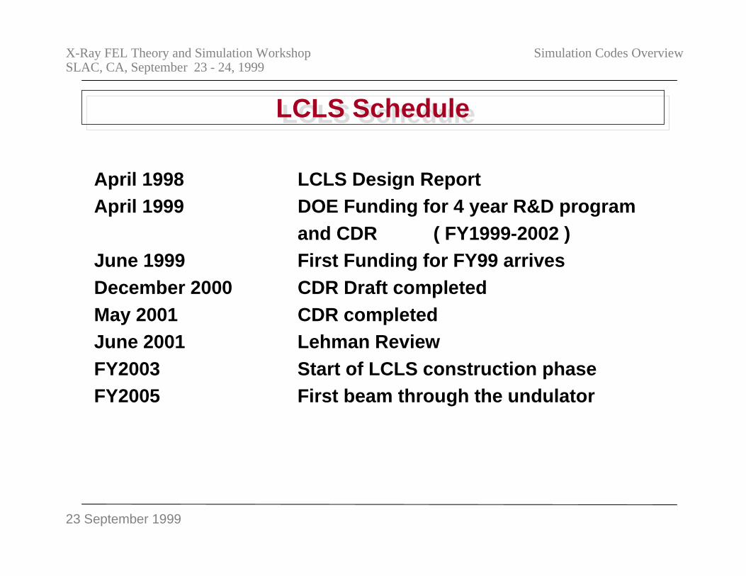
LCLS ScheduleLCLS Schedule
April 1998 LCLS Design ReportApril 1999 DOE Funding for 4 year R&D program
and CDR ( FY1999-2002 )June 1999 First Funding for FY99 arrivesDecember 2000 CDR Draft completedMay 2001 CDR completedJune 2001 Lehman ReviewFY2003 Start of LCLS construction phaseFY2005 First beam through the undulator
23 September 1999
X-Ray FEL Theory and Simulation WorkshopSLAC, CA, September 23 - 24, 1999
Simulation Codes Overview
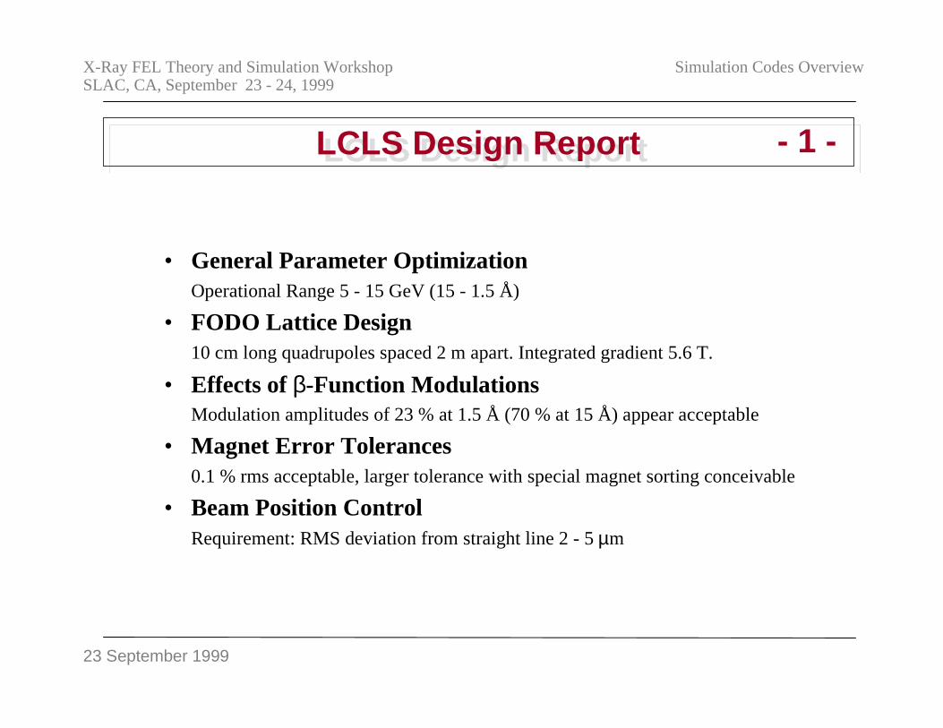
LCLS Design ReportLCLS Design Report
• General Parameter OptimizationOperational Range 5 - 15 GeV (15 - 1.5 Å)
• FODO Lattice Design10 cm long quadrupoles spaced 2 m apart. Integrated gradient 5.6 T.
• Effects of β-Function ModulationsModulation amplitudes of 23 % at 1.5 Å (70 % at 15 Å) appear acceptable
• Magnet Error Tolerances0.1 % rms acceptable, larger tolerance with special magnet sorting conceivable
• Beam Position ControlRequirement: RMS deviation from straight line 2 - 5 µm
- 1 -
23 September 1999
X-Ray FEL Theory and Simulation WorkshopSLAC, CA, September 23 - 24, 1999
Simulation Codes Overview
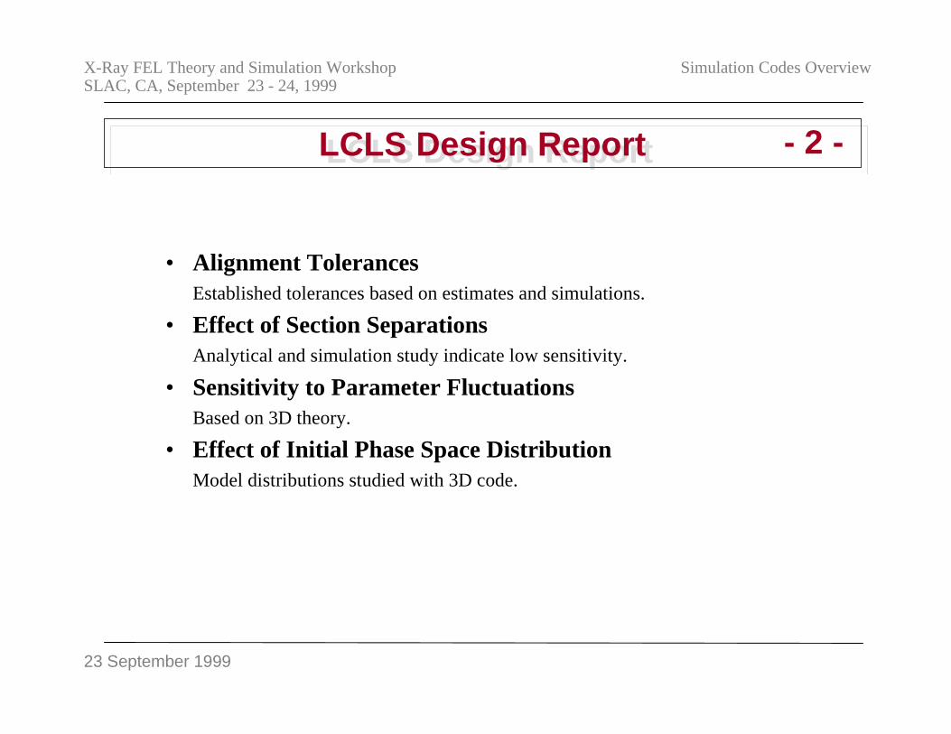
LCLS Design ReportLCLS Design Report
• Alignment TolerancesEstablished tolerances based on estimates and simulations.
• Effect of Section SeparationsAnalytical and simulation study indicate low sensitivity.
• Sensitivity to Parameter FluctuationsBased on 3D theory.
• Effect of Initial Phase Space DistributionModel distributions studied with 3D code.
- 2 -
23 September 1999
X-Ray FEL Theory and Simulation WorkshopSLAC, CA, September 23 - 24, 1999
Simulation Codes Overview
LCLS Design ReportLCLS Design Report
• Effects of Spontaneous RadiationEstimate of effects of energy spread and emittance increase to be small. EnergyLoss of .15 % will require micro-tapering.
• Effects of Wall Roughness and Resistive Wall Impedance.Simulation of energy-change dependence on position within a bunch with modifiedGINGER code. Tolerance .1% over 100 m undulator at 15 GeV. Average changeto be corrected with additional micro-tapering.
• Output Power ControlBased on GINGER simulations. Operation in exponential gain regime leads tounacceptable fluctuations.
- 3 -
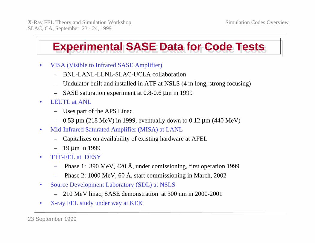
23 September 1999
X-Ray FEL Theory and Simulation WorkshopSLAC, CA, September 23 - 24, 1999
Simulation Codes Overview
• VISA (Visible to Infrared SASE Amplifier)
– BNL-LANL-LLNL-SLAC-UCLA collaboration
– Undulator built and installed in ATF at NSLS (4 m long, strong focusing)
– SASE saturation experiment at 0.8-0.6 µm in 1999
• LEUTL at ANL
– Uses part of the APS Linac
– 0.53 µm (218 MeV) in 1999, eventually down to 0.12 µm (440 MeV)
• Mid-Infrared Saturated Amplifier (MISA) at LANL
– Capitalizes on availability of existing hardware at AFEL
– 19 µm in 1999
• TTF-FEL at DESY
– Phase 1: 390 MeV, 420 Å, under comissioning, first operation 1999
– Phase 2: 1000 MeV, 60 Å, start commissioning in March, 2002
• Source Development Laboratory (SDL) at NSLS
– 210 MeV linac, SASE demonstration at 300 nm in 2000-2001
• X-ray FEL study under way at KEK
Experimental SASE Data for Code TestsExperimental SASE Data for Code Tests
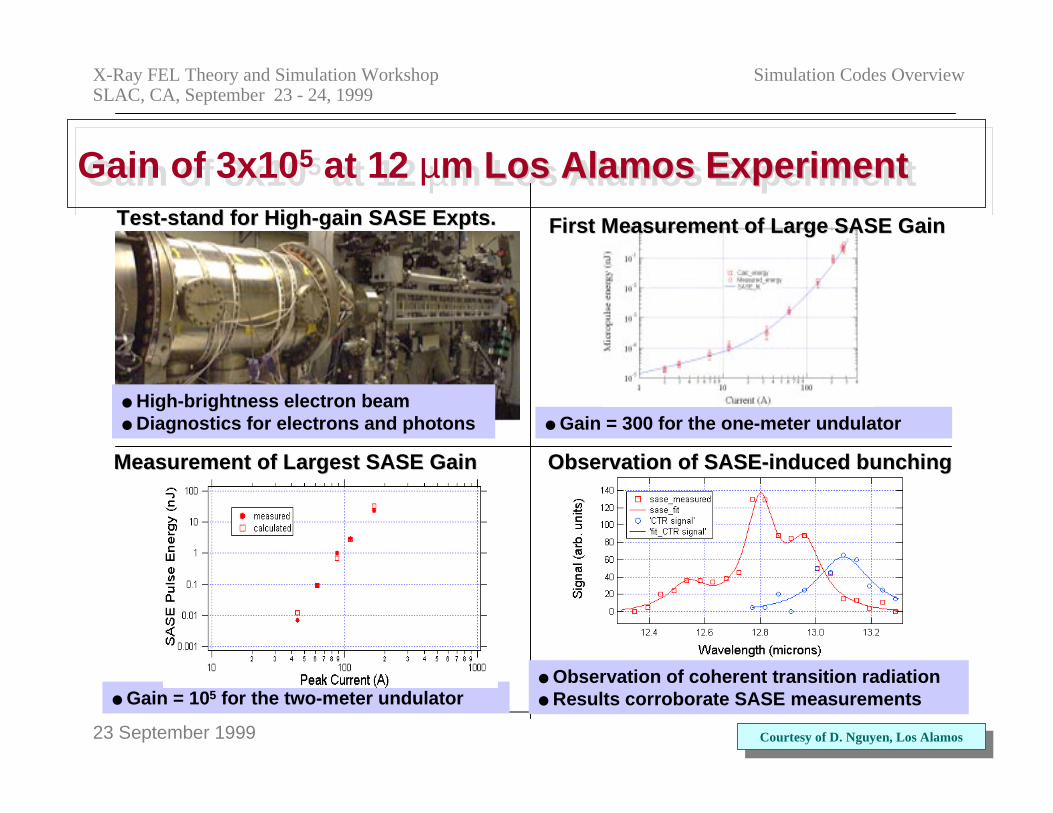
23 September 1999
X-Ray FEL Theory and Simulation WorkshopSLAC, CA, September 23 - 24, 1999
Simulation Codes Overview
Gain of 3x10⁵ at 12 µm Los Alamos ExperimentGain of 3x10⁵ at 12 µm Los Alamos Experiment Los Alamos ExperimentTest-stand for High-gain SASE Test-stand for High-gain SASE ExptsExpts..
Gain = 105 for the two-meter undulator
Observation of SASE-induced bunchingObservation of SASE-induced bunchingMeasurement of Largest SASE GainMeasurement of Largest SASE Gain
Observation of coherent transition radiation Results corroborate SASE measurements
Gain = 300 for the one-meter undulator High-brightness electron beam Diagnostics for electrons and photons
Courtesy of D. Nguyen, Los AlamosCourtesy of D. Nguyen, Los Alamos
First Measurement of Large SASE GainFirst Measurement of Large SASE Gain
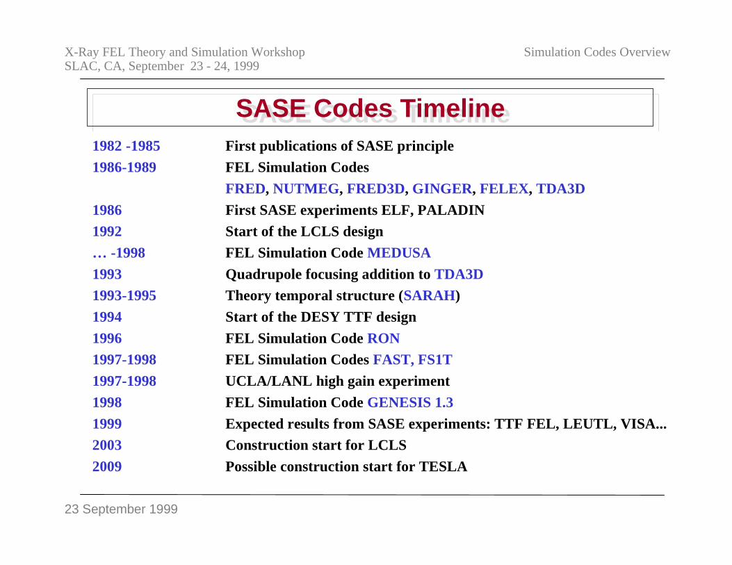
23 September 1999
X-Ray FEL Theory and Simulation WorkshopSLAC, CA, September 23 - 24, 1999
Simulation Codes Overview
SASE Codes TimelineSASE Codes Timeline1982 -1985 First publications of SASE principle
1986-1989 FEL Simulation Codes
FRED, NUTMEG, FRED3D, GINGER, FELEX, TDA3D
1986 First SASE experiments ELF, PALADIN
1992 Start of the LCLS design
… -1998 FEL Simulation Code MEDUSA
1993 Quadrupole focusing addition to TDA3D
1993-1995 Theory temporal structure (SARAH)
1994 Start of the DESY TTF design
1996 FEL Simulation Code RON
1997-1998 FEL Simulation Codes FAST, FS1T
1997-1998 UCLA/LANL high gain experiment
1998 FEL Simulation Code GENESIS 1.3
1999 Expected results from SASE experiments: TTF FEL, LEUTL, VISA...
2003 Construction start for LCLS
2009 Possible construction start for TESLA
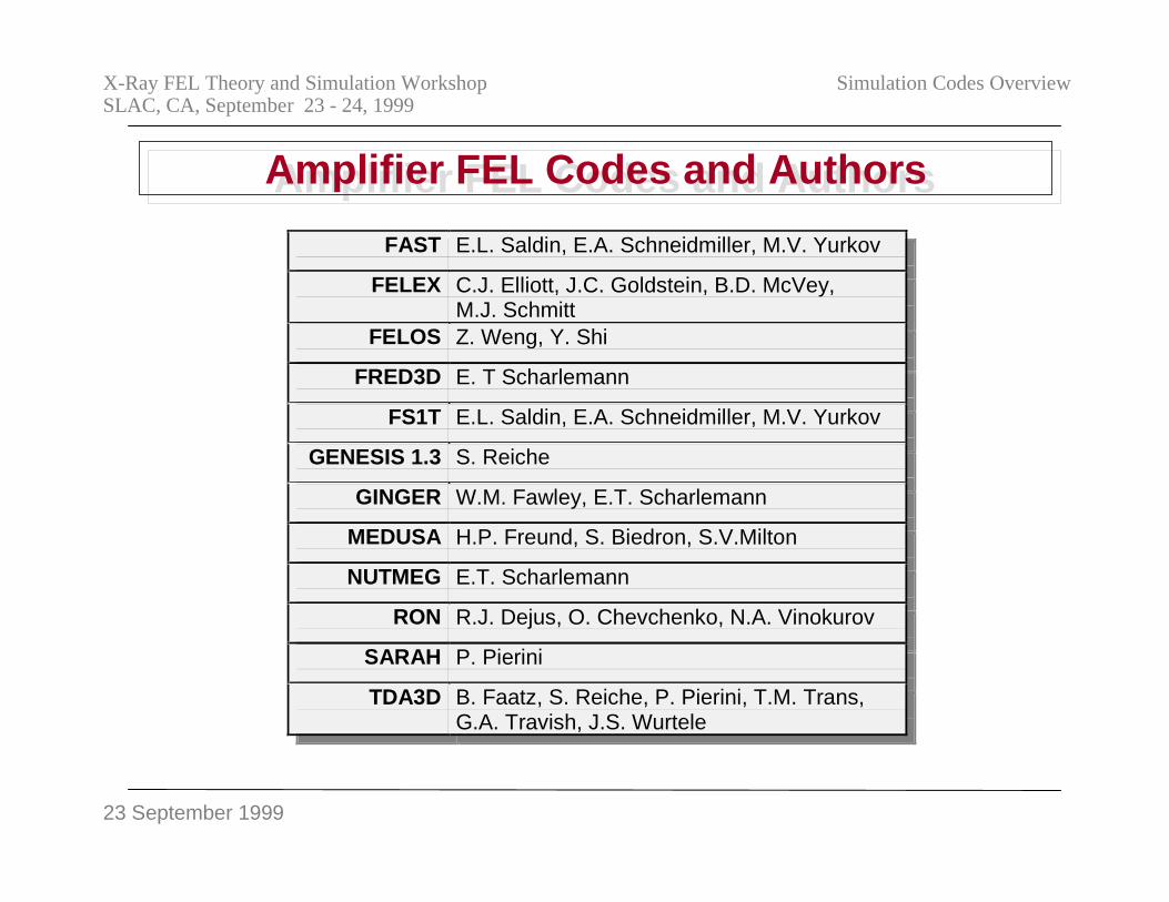
23 September 1999
X-Ray FEL Theory and Simulation WorkshopSLAC, CA, September 23 - 24, 1999
Simulation Codes Overview
Amplifier FEL Codes and AuthorsAmplifier FEL Codes and Authors
FAST E.L. Saldin, E.A. Schneidmiller, M.V. Yurkov
FELEX C.J. Elliott, J.C. Goldstein, B.D. McVey,M.J. Schmitt
FELOS Z. Weng, Y. Shi
FRED3D E. T Scharlemann
FS1T E.L. Saldin, E.A. Schneidmiller, M.V. Yurkov
GENESIS 1.3 S. Reiche
GINGER W.M. Fawley, E.T. Scharlemann
MEDUSA H.P. Freund, S. Biedron, S.V.Milton
NUTMEG E.T. Scharlemann
RON R.J. Dejus, O. Chevchenko, N.A. Vinokurov
SARAH P. Pierini
TDA3D B. Faatz, S. Reiche, P. Pierini, T.M. Trans,G.A. Travish, J.S. Wurtele
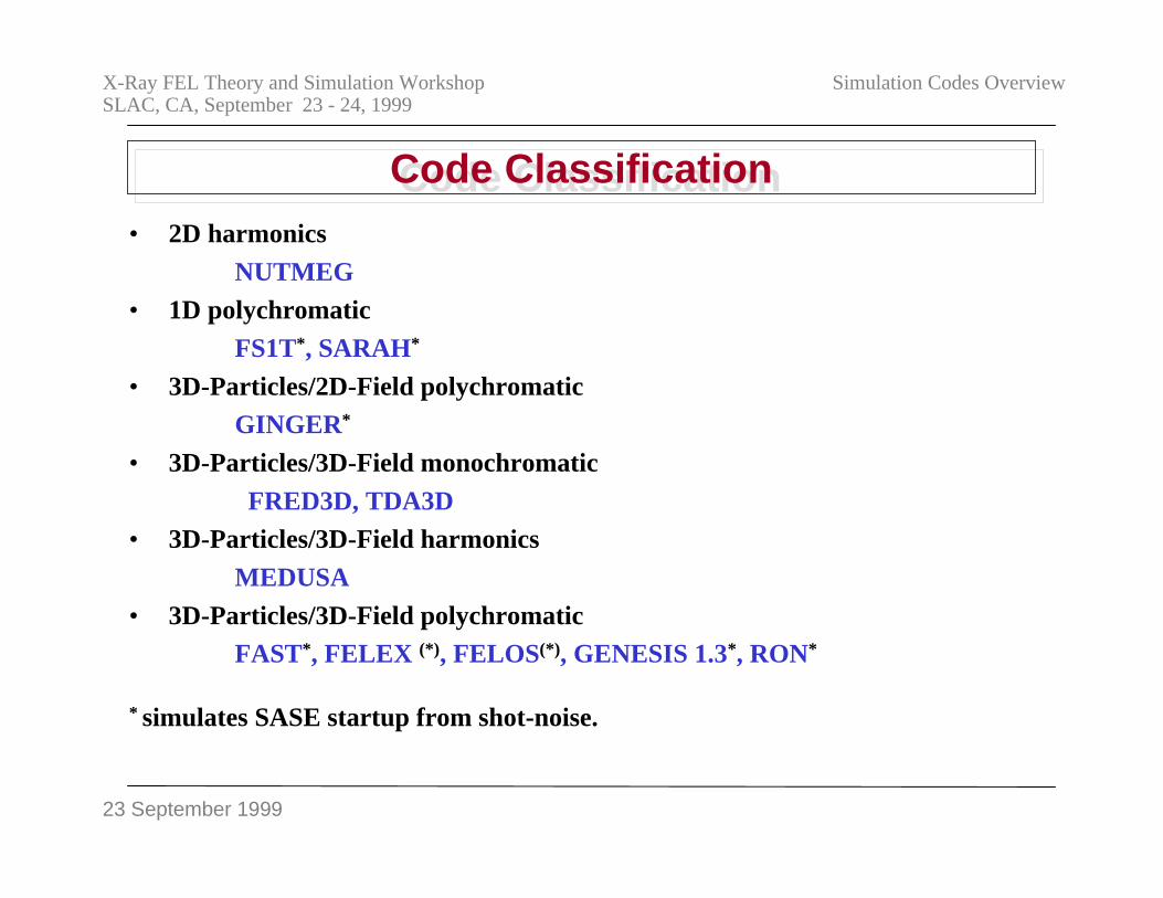
23 September 1999
X-Ray FEL Theory and Simulation WorkshopSLAC, CA, September 23 - 24, 1999
Simulation Codes Overview
Code ClassificationCode Classification• 2D harmonics
NUTMEG• 1D polychromatic
FS1T*, SARAH*
• 3D-Particles/2D-Field polychromaticGINGER*
• 3D-Particles/3D-Field monochromatic
FRED3D, TDA3D• 3D-Particles/3D-Field harmonics
MEDUSA
• 3D-Particles/3D-Field polychromaticFAST*, FELEX (*), FELOS(*), GENESIS 1.3*, RON*
* simulates SASE startup from shot-noise.
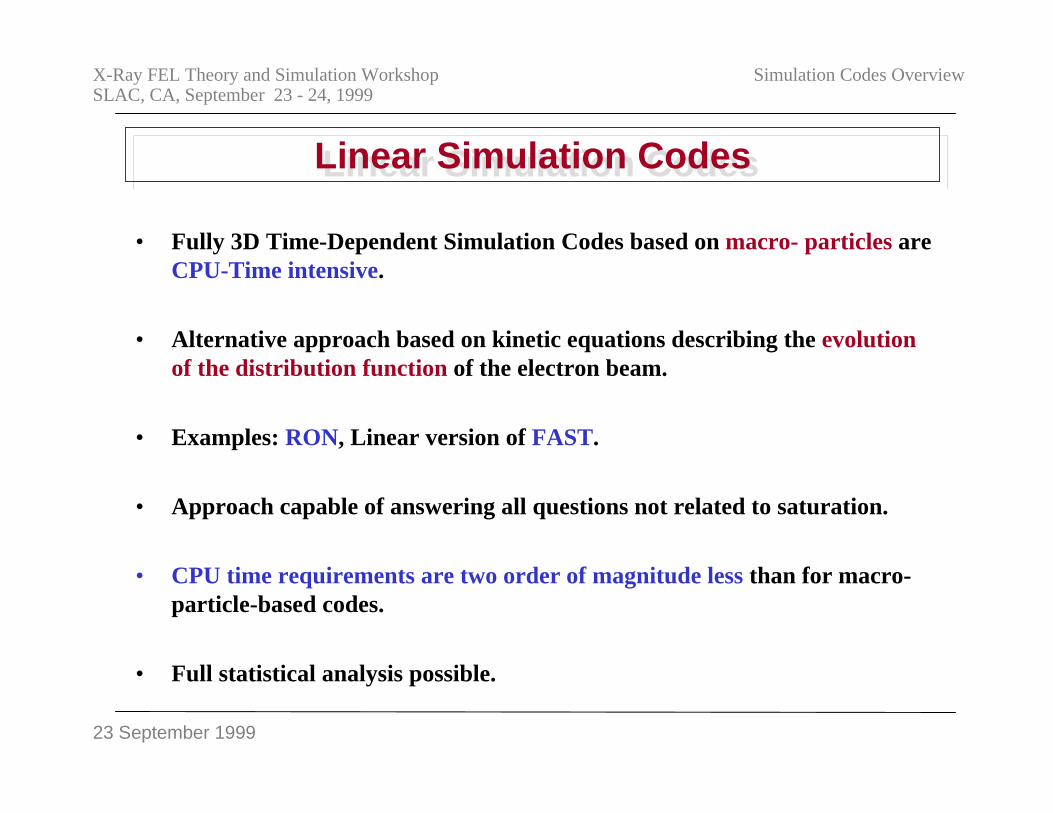
23 September 1999
X-Ray FEL Theory and Simulation WorkshopSLAC, CA, September 23 - 24, 1999
Simulation Codes Overview
Linear Simulation CodesLinear Simulation Codes
• Fully 3D Time-Dependent Simulation Codes based on macro- particles areCPU-Time intensive.
• Alternative approach based on kinetic equations describing the evolutionof the distribution function of the electron beam.
• Examples: RON, Linear version of FAST.
• Approach capable of answering all questions not related to saturation.
• CPU time requirements are two order of magnitude less than for macro-particle-based codes.
• Full statistical analysis possible.
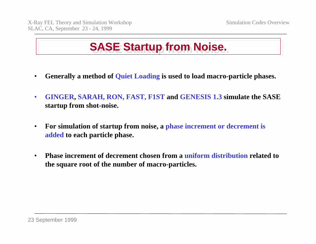
23 September 1999
X-Ray FEL Theory and Simulation WorkshopSLAC, CA, September 23 - 24, 1999
Simulation Codes Overview
SASE Startup from Noise.SASE Startup from Noise.
• Generally a method of Quiet Loading is used to load macro-particle phases.
• GINGER, SARAH, RON, FAST, F1ST and GENESIS 1.3 simulate the SASEstartup from shot-noise.
• For simulation of startup from noise, a phase increment or decrement isadded to each particle phase.
• Phase increment of decrement chosen from a uniform distribution related tothe square root of the number of macro-particles.
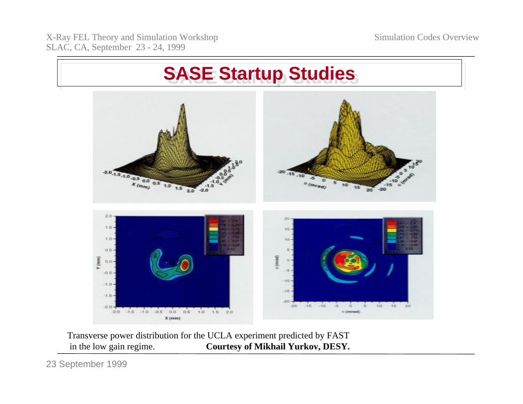
23 September 1999
X-Ray FEL Theory and Simulation WorkshopSLAC, CA, September 23 - 24, 1999
Simulation Codes Overview
SASE Startup StudiesSASE Startup Studies
Transverse power distribution for the UCLA experiment predicted by FAST in the low gain regime. Courtesy of Mikhail Yurkov, DESY.
23 September 1999
X-Ray FEL Theory and Simulation WorkshopSLAC, CA, September 23 - 24, 1999
Simulation Codes Overview
Statistical AnalysisStatistical Analysis
• Simulation results are dependent on seeding of particle and fielddistributions.
• Limited information obtainable from single run.
• Distribution of simulation results relevant.
• Many simulation runs required to answer each problem.• Not accessible yet for macro-particle codes due to CPU time requirements.
• Can be done with linear codes.
• Multiprocessor Farms could be suitable:
Different seeding on each processor.
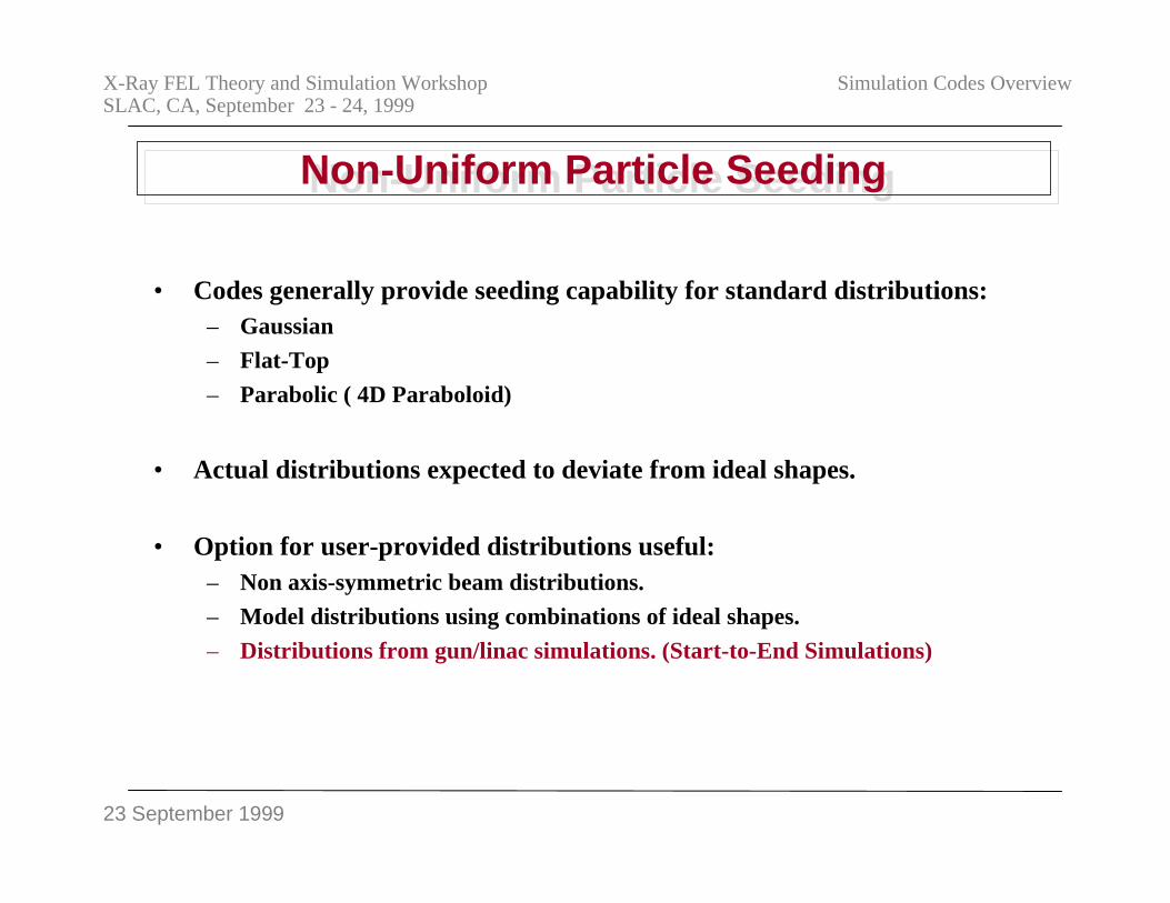
23 September 1999
X-Ray FEL Theory and Simulation WorkshopSLAC, CA, September 23 - 24, 1999
Simulation Codes Overview
Non-Uniform Particle SeedingNon-Uniform Particle Seeding
• Codes generally provide seeding capability for standard distributions:– Gaussian
– Flat-Top
– Parabolic ( 4D Paraboloid)
• Actual distributions expected to deviate from ideal shapes.
• Option for user-provided distributions useful:– Non axis-symmetric beam distributions.
– Model distributions using combinations of ideal shapes.
– Distributions from gun/linac simulations. (Start-to-End Simulations)
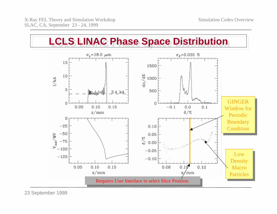
23 September 1999
X-Ray FEL Theory and Simulation WorkshopSLAC, CA, September 23 - 24, 1999
Simulation Codes Overview
LCLS LINAC Phase Space DistributionLCLS LINAC Phase Space Distribution
GINGERWindow for
PeriodicBoundaryCondition
GINGERWindow for
PeriodicBoundaryCondition
LowDensityMacro
Particles
LowDensityMacro
Particles
Requires User Interface to select Slice Position.Requires User Interface to select Slice Position.
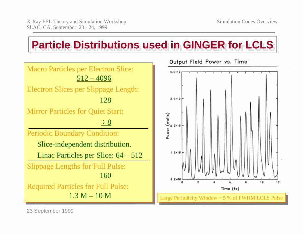
23 September 1999
X-Ray FEL Theory and Simulation WorkshopSLAC, CA, September 23 - 24, 1999
Simulation Codes Overview
Particle Distributions used in GINGER for LCLSParticle Distributions used in GINGER for LCLS
Macro Particles per Electron Slice:512 – 4096
Electron Slices per Slippage Length:
128
Mirror Particles for Quiet Start:
÷ 8
Periodic Boundary Condition:
Slice-independent distribution.
Linac Particles per Slice: 64 – 512
Slippage Lengths for Full Pulse: 160
Required Particles for Full Pulse:1.3 M – 10 M
Large Periodicity Window ~ 5 % of FWHM LCLS PulseLarge Periodicity Window ~ 5 % of FWHM LCLS Pulse
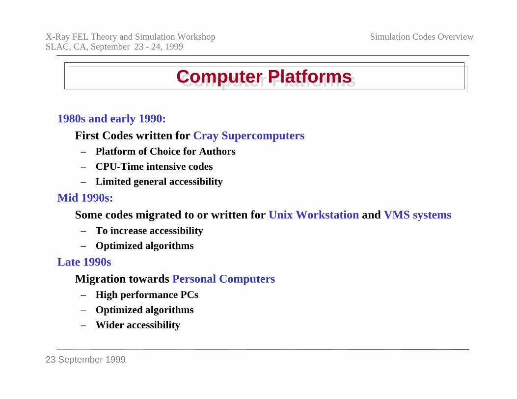
23 September 1999
X-Ray FEL Theory and Simulation WorkshopSLAC, CA, September 23 - 24, 1999
Simulation Codes Overview
Computer PlatformsComputer Platforms
1980s and early 1990:First Codes written for Cray Supercomputers
– Platform of Choice for Authors
– CPU-Time intensive codes
– Limited general accessibility
Mid 1990s:
Some codes migrated to or written for Unix Workstation and VMS systems– To increase accessibility
– Optimized algorithms
Late 1990sMigration towards Personal Computers
– High performance PCs
– Optimized algorithms
– Wider accessibility
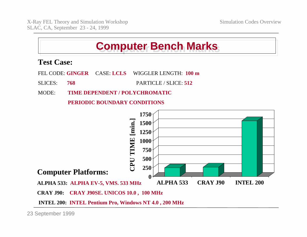
23 September 1999
X-Ray FEL Theory and Simulation WorkshopSLAC, CA, September 23 - 24, 1999
Simulation Codes Overview
Computer Bench MarksComputer Bench Marks
0
250
500
750
1000
1250
1500
1750
CP
U T
IME
[m
in.]
ALPHA 533 CRAY J90 INTEL 200
Test Case:FEL CODE: GINGER CASE: LCLS WIGGLER LENGTH: 100 m
SLICES: 768 PARTICLE / SLICE: 512
MODE: TIME DEPENDENT / POLYCHROMATIC
PERIODIC BOUNDARY CONDITIONS
Computer Platforms:ALPHA 533: ALPHA EV-5, VMS. 533 MHz
CRAY J90: CRAY J90SE. UNICOS 10.0 , 100 MHz
INTEL 200: INTEL Pentium Pro, Windows NT 4.0 , 200 MHz
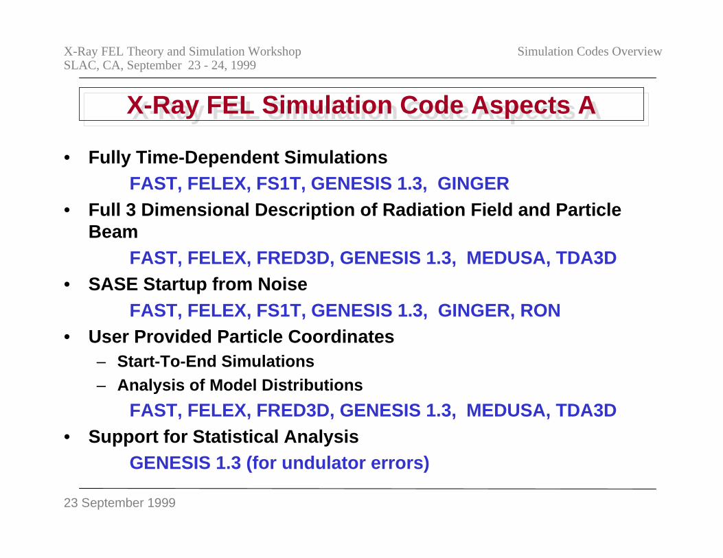
23 September 1999
X-Ray FEL Theory and Simulation WorkshopSLAC, CA, September 23 - 24, 1999
Simulation Codes Overview
X-Ray FEL Simulation Code Aspects AX-Ray FEL Simulation Code Aspects A
• Fully Time-Dependent SimulationsFAST, FELEX, FS1T, GENESIS 1.3, GINGER
• Full 3 Dimensional Description of Radiation Field and ParticleBeam
FAST, FELEX, FRED3D, GENESIS 1.3, MEDUSA, TDA3D• SASE Startup from Noise
FAST, FELEX, FS1T, GENESIS 1.3, GINGER, RON• User Provided Particle Coordinates
– Start-To-End Simulations– Analysis of Model Distributions
FAST, FELEX, FRED3D, GENESIS 1.3, MEDUSA, TDA3D• Support for Statistical Analysis
GENESIS 1.3 (for undulator errors)
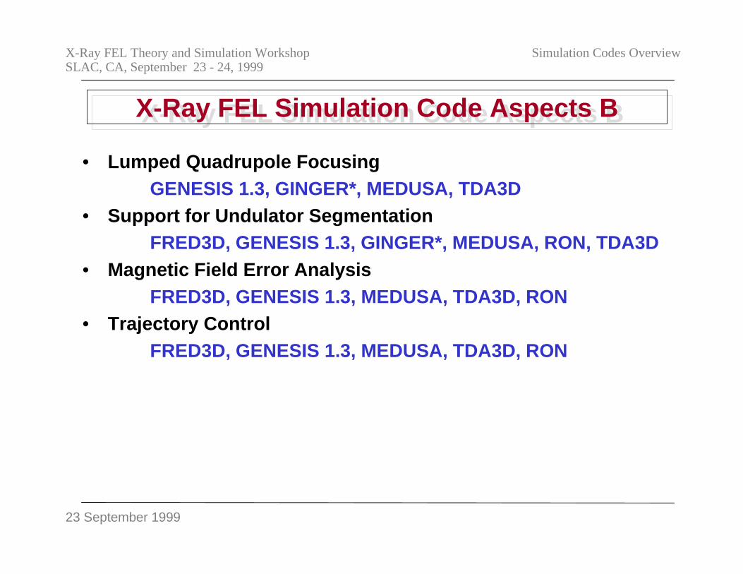
23 September 1999
X-Ray FEL Theory and Simulation WorkshopSLAC, CA, September 23 - 24, 1999
Simulation Codes Overview
X-Ray FEL Simulation Code Aspects BX-Ray FEL Simulation Code Aspects B
• Lumped Quadrupole FocusingGENESIS 1.3, GINGER*, MEDUSA, TDA3D
• Support for Undulator SegmentationFRED3D, GENESIS 1.3, GINGER*, MEDUSA, RON, TDA3D
• Magnetic Field Error AnalysisFRED3D, GENESIS 1.3, MEDUSA, TDA3D, RON
• Trajectory ControlFRED3D, GENESIS 1.3, MEDUSA, TDA3D, RON
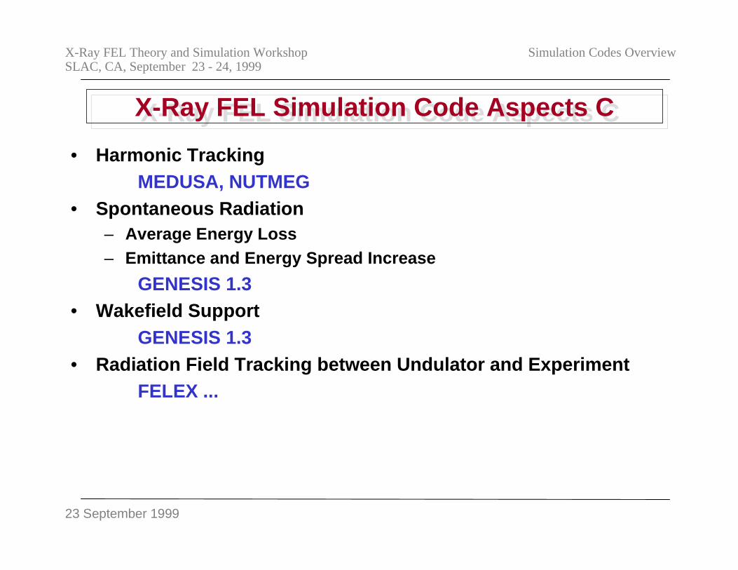
23 September 1999
X-Ray FEL Theory and Simulation WorkshopSLAC, CA, September 23 - 24, 1999
Simulation Codes Overview
X-Ray FEL Simulation Code Aspects CX-Ray FEL Simulation Code Aspects C
• Harmonic TrackingMEDUSA, NUTMEG
• Spontaneous Radiation– Average Energy Loss– Emittance and Energy Spread Increase
GENESIS 1.3• Wakefield Support
GENESIS 1.3• Radiation Field Tracking between Undulator and Experiment
FELEX ...
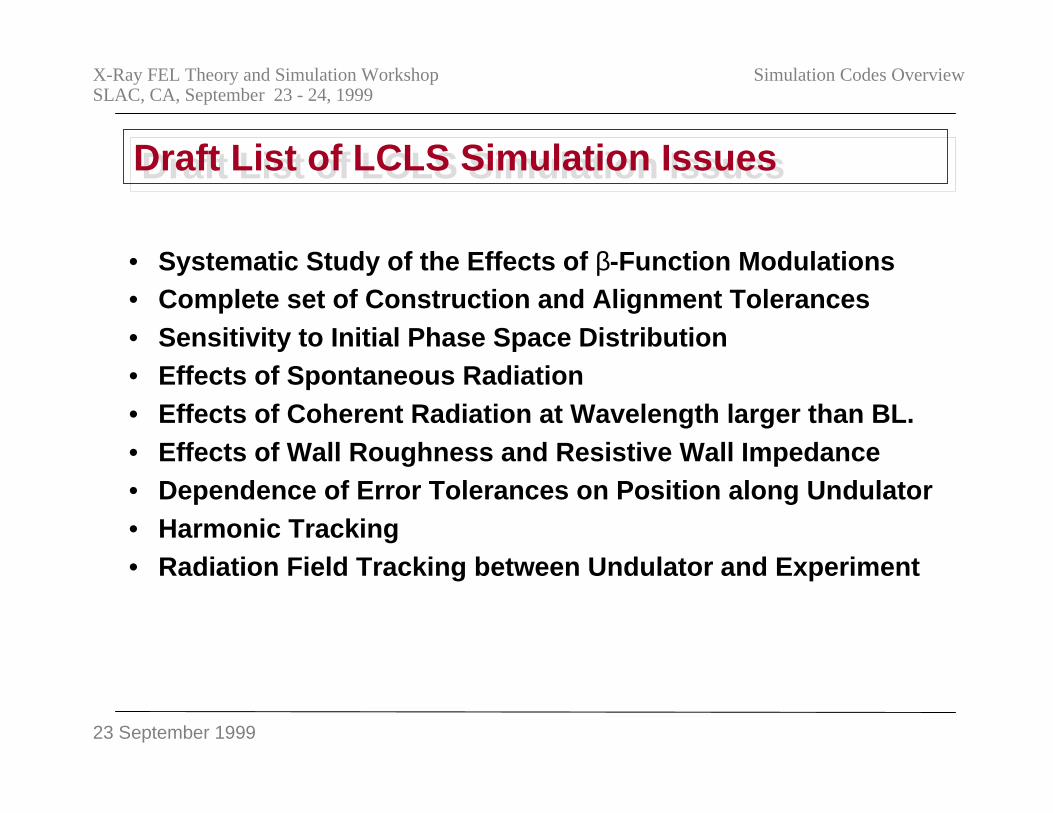
23 September 1999
X-Ray FEL Theory and Simulation WorkshopSLAC, CA, September 23 - 24, 1999
Simulation Codes Overview
Draft List of LCLS Simulation IssuesDraft List of LCLS Simulation Issues
• Systematic Study of the Effects of β-Function Modulations• Complete set of Construction and Alignment Tolerances• Sensitivity to Initial Phase Space Distribution• Effects of Spontaneous Radiation• Effects of Coherent Radiation at Wavelength larger than BL.• Effects of Wall Roughness and Resistive Wall Impedance• Dependence of Error Tolerances on Position along Undulator• Harmonic Tracking• Radiation Field Tracking between Undulator and Experiment
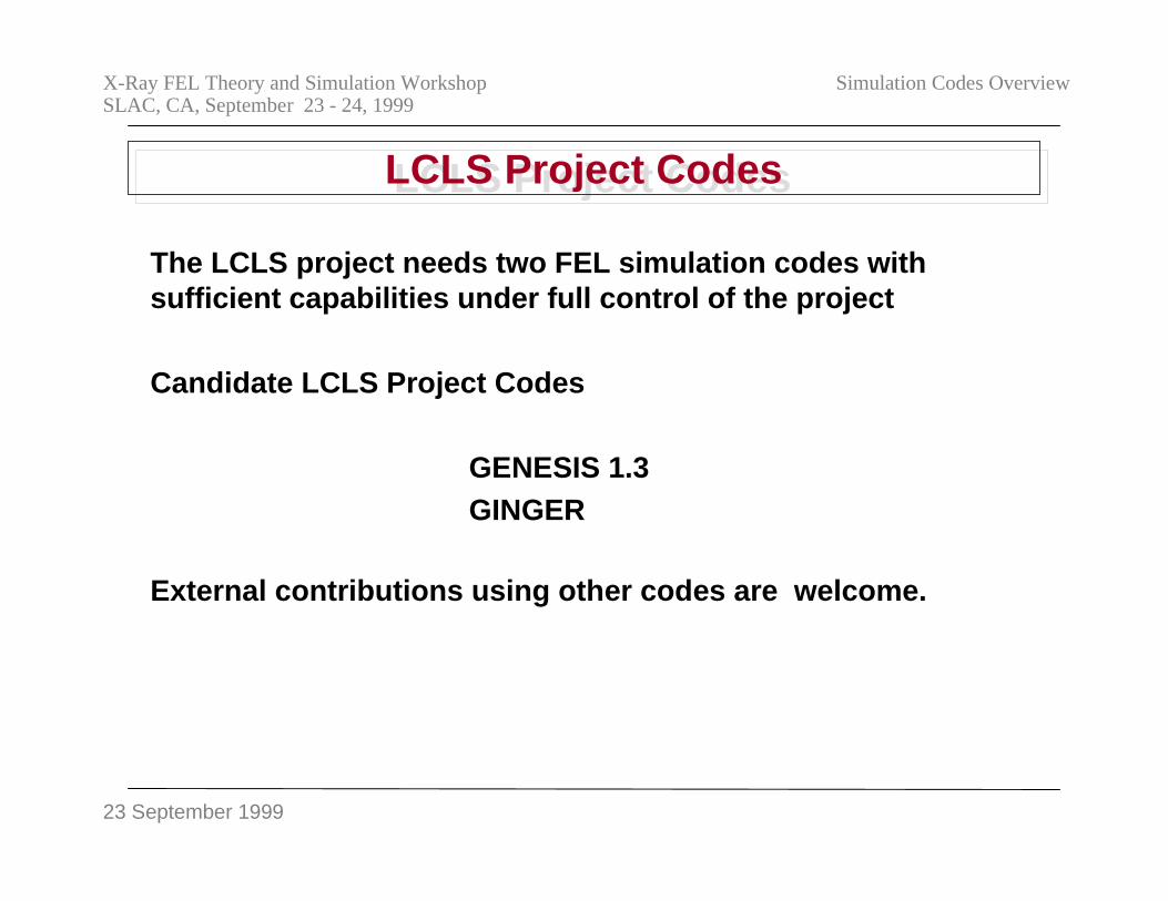
23 September 1999
X-Ray FEL Theory and Simulation WorkshopSLAC, CA, September 23 - 24, 1999
Simulation Codes Overview
LCLS Project CodesLCLS Project Codes
The LCLS project needs two FEL simulation codes withsufficient capabilities under full control of the project
Candidate LCLS Project Codes
GENESIS 1.3GINGER
External contributions using other codes are welcome.
23 September 1999
X-Ray FEL Theory and Simulation WorkshopSLAC, CA, September 23 - 24, 1999
Simulation Codes Overview
ConclusionsConclusions
• The initial basic design of the LCLS has been completed inthe LCLS Design Study report.
• More detailed study will be done for the CDR.• New experimental results expected starting in next 12
months.• A number of FEL simulation codes exists. Not all necessary
features are included.• Code upgrade program is underway and will receive
guidance from the workshop.• Workshop will focus around the undulator, i.e., from the
linac phase space distribution to the description of theradiation field out of the linac.
23 September 1999
X-Ray FEL Theory and Simulation WorkshopSLAC, CA, September 23 - 24, 1999
Simulation Codes Overview
X-Ray FEL Theory and Simulation Codes Workshop SLAC, September 23-24. 1999
- 77 -
WORKSHOP PRESENTATIONS III
Remarks on SASE Fluctuations and Undulator ErrorsK.-J. Kim

X-Ray FEL Theory and Simulation Codes Workshop SLAC, September 23-24. 1999
- 78 -
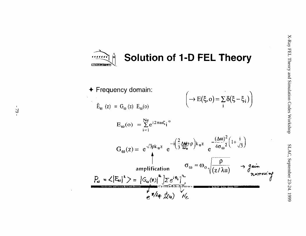
X-R
ay FEL
Theory and Sim
ulation Codes W
orkshopS
LA
C, Septem
ber 23-24. 1999
- 79 -
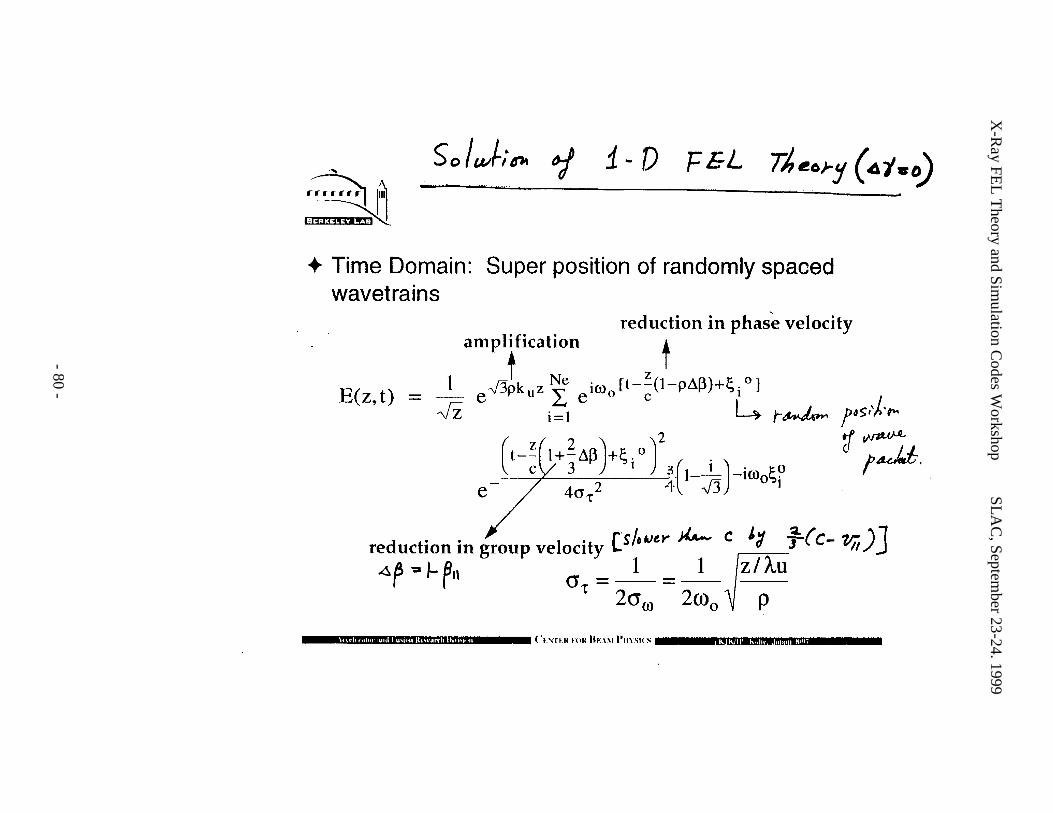
X-R
ay FEL
Theory and Sim
ulation Codes W
orkshopS
LA
C, Septem
ber 23-24. 1999
- 80 -
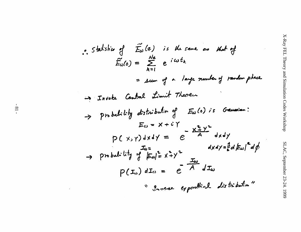
X-R
ay FEL
Theory and Sim
ulation Codes W
orkshopS
LA
C, Septem
ber 23-24. 1999
- 81 -
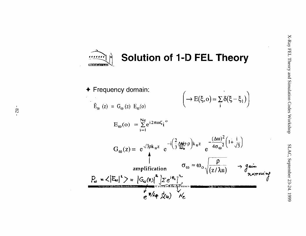
X-R
ay FEL
Theory and Sim
ulation Codes W
orkshopS
LA
C, Septem
ber 23-24. 1999
- 82 -
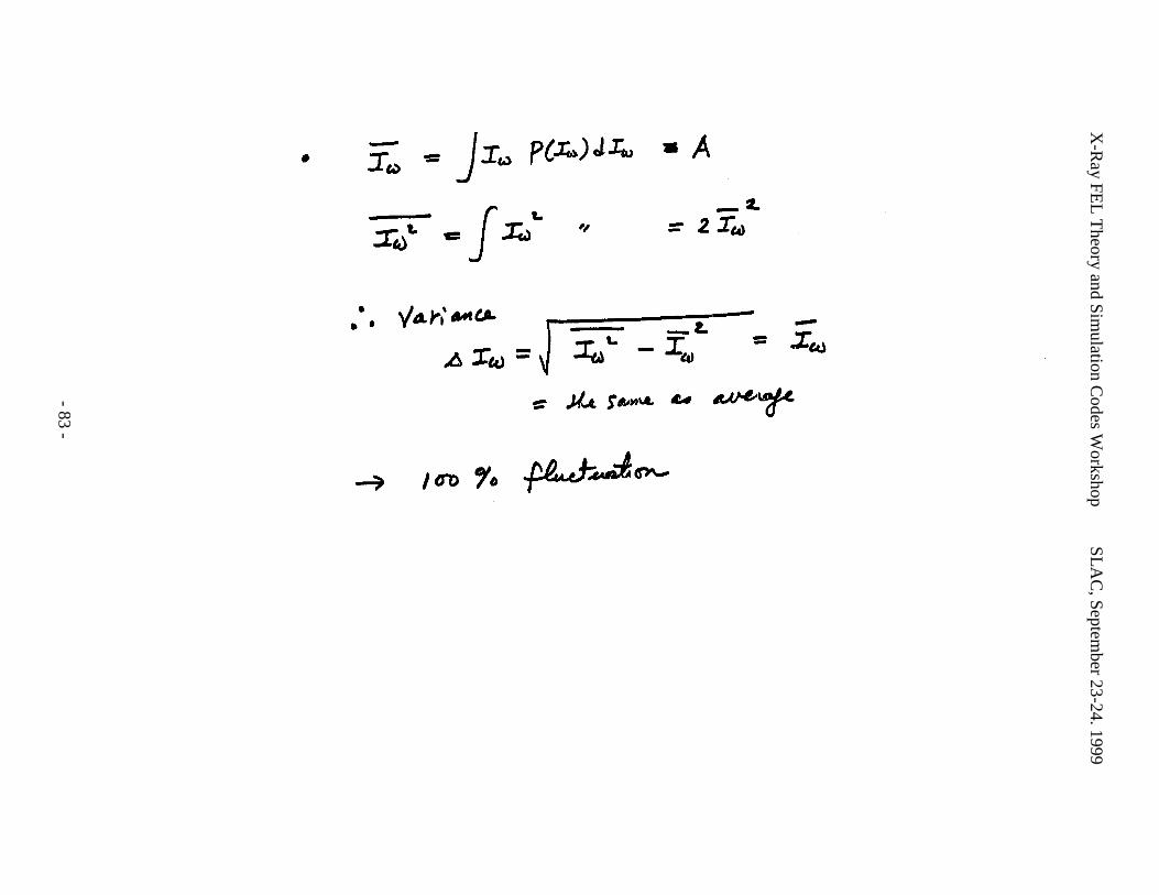
X-R
ay FEL
Theory and Sim
ulation Codes W
orkshopS
LA
C, Septem
ber 23-24. 1999
- 83 -
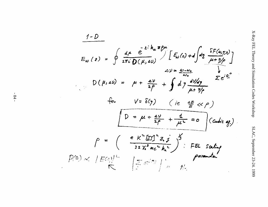
X-R
ay FEL
Theory and Sim
ulation Codes W
orkshopS
LA
C, Septem
ber 23-24. 1999
- 84 -
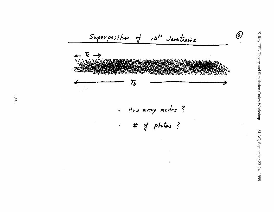
X-R
ay FEL
Theory and Sim
ulation Codes W
orkshopS
LA
C, Septem
ber 23-24. 1999
- 85 -
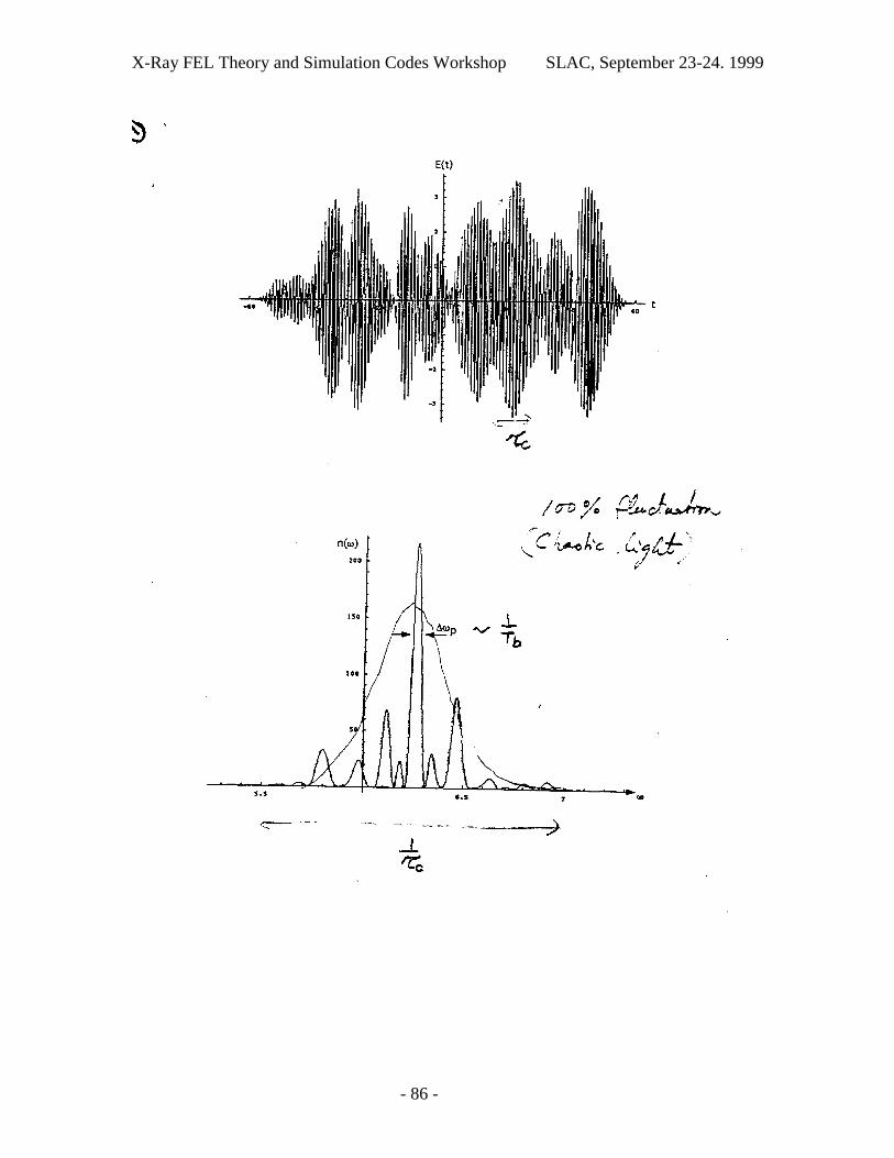
X-Ray FEL Theory and Simulation Codes Workshop SLAC, September 23-24. 1999
- 86 -
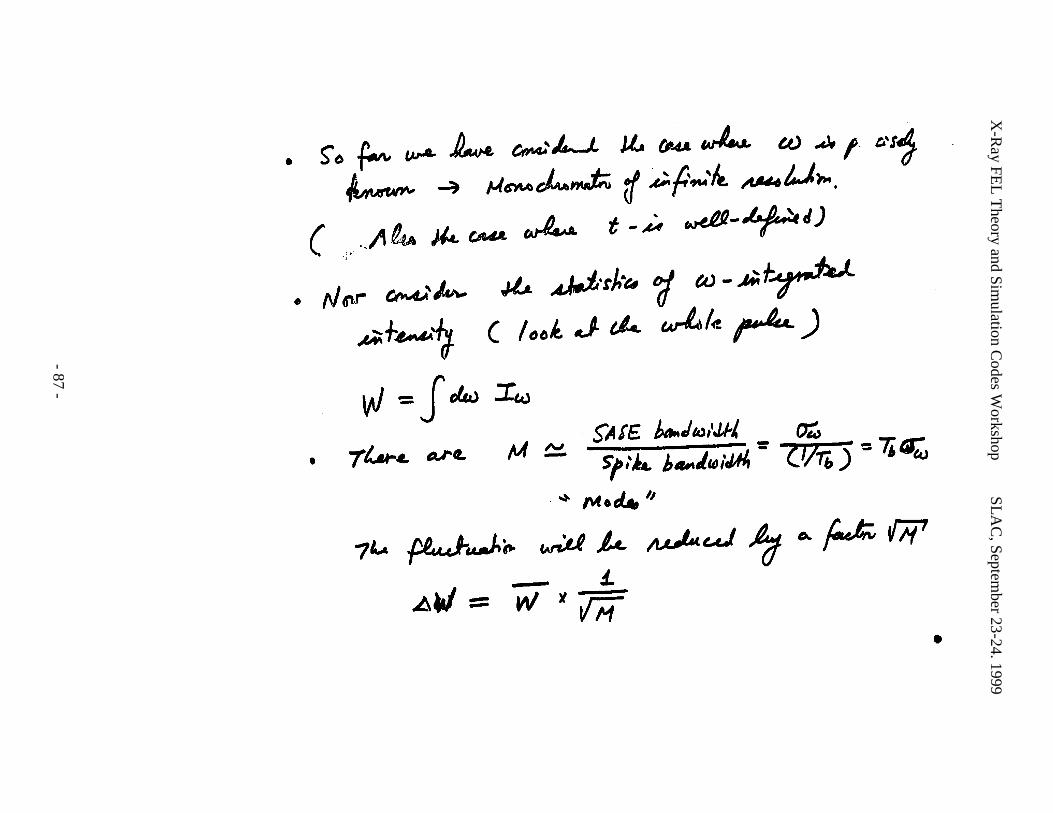
X-R
ay FEL
Theory and Sim
ulation Codes W
orkshopS
LA
C, Septem
ber 23-24. 1999
- 87 -
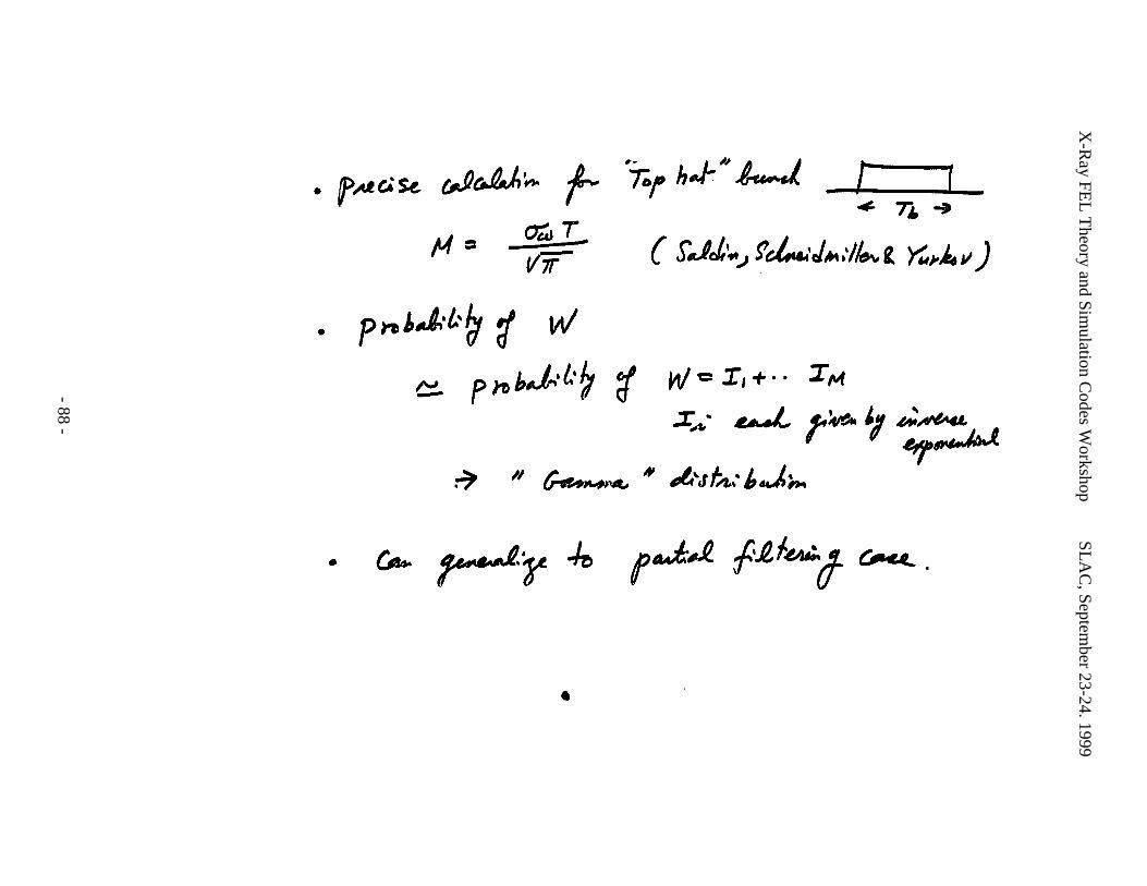
X-R
ay FEL
Theory and Sim
ulation Codes W
orkshopS
LA
C, Septem
ber 23-24. 1999
- 88 -
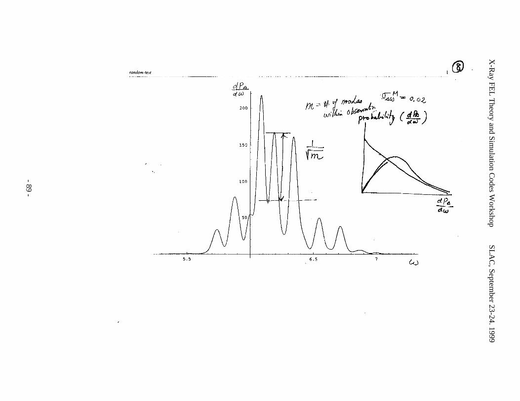
X-R
ay FEL
Theory and Sim
ulation Codes W
orkshopS
LA
C, Septem
ber 23-24. 1999
- 89 -
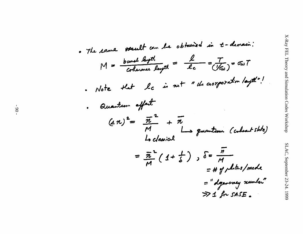
X-R
ay FEL
Theory and Sim
ulation Codes W
orkshopS
LA
C, Septem
ber 23-24. 1999
- 90 -
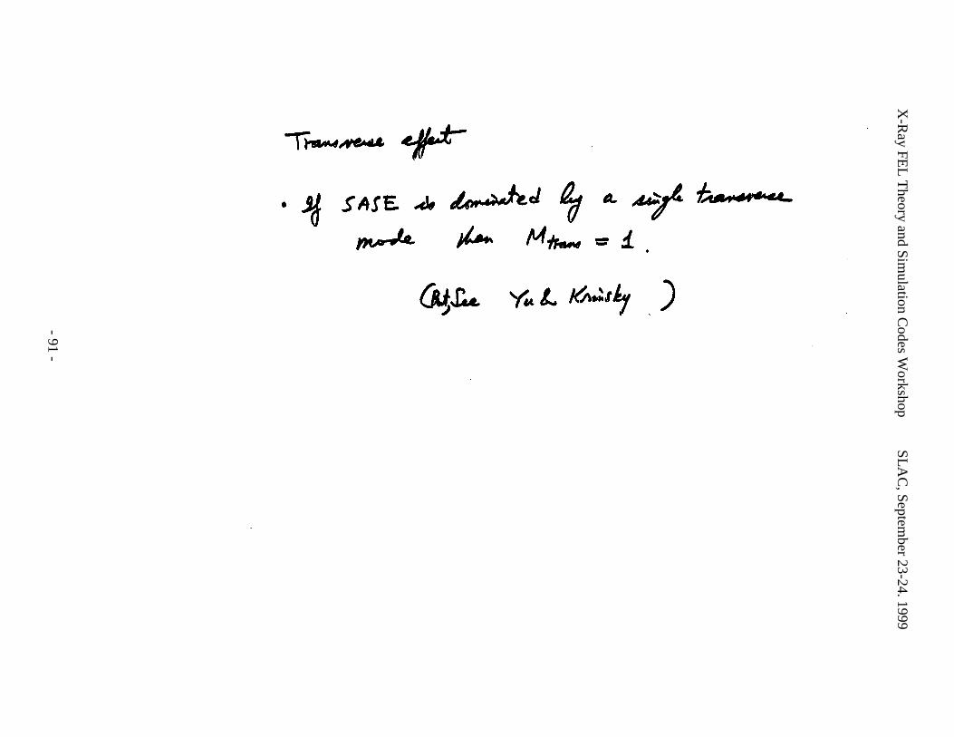
X-R
ay FEL
Theory and Sim
ulation Codes W
orkshopS
LA
C, Septem
ber 23-24. 1999
- 91 -
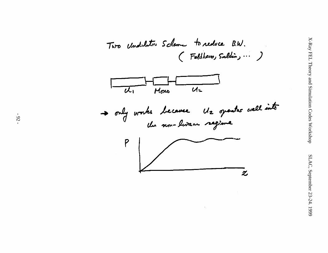
X-R
ay FEL
Theory and Sim
ulation Codes W
orkshopS
LA
C, Septem
ber 23-24. 1999
- 92 -
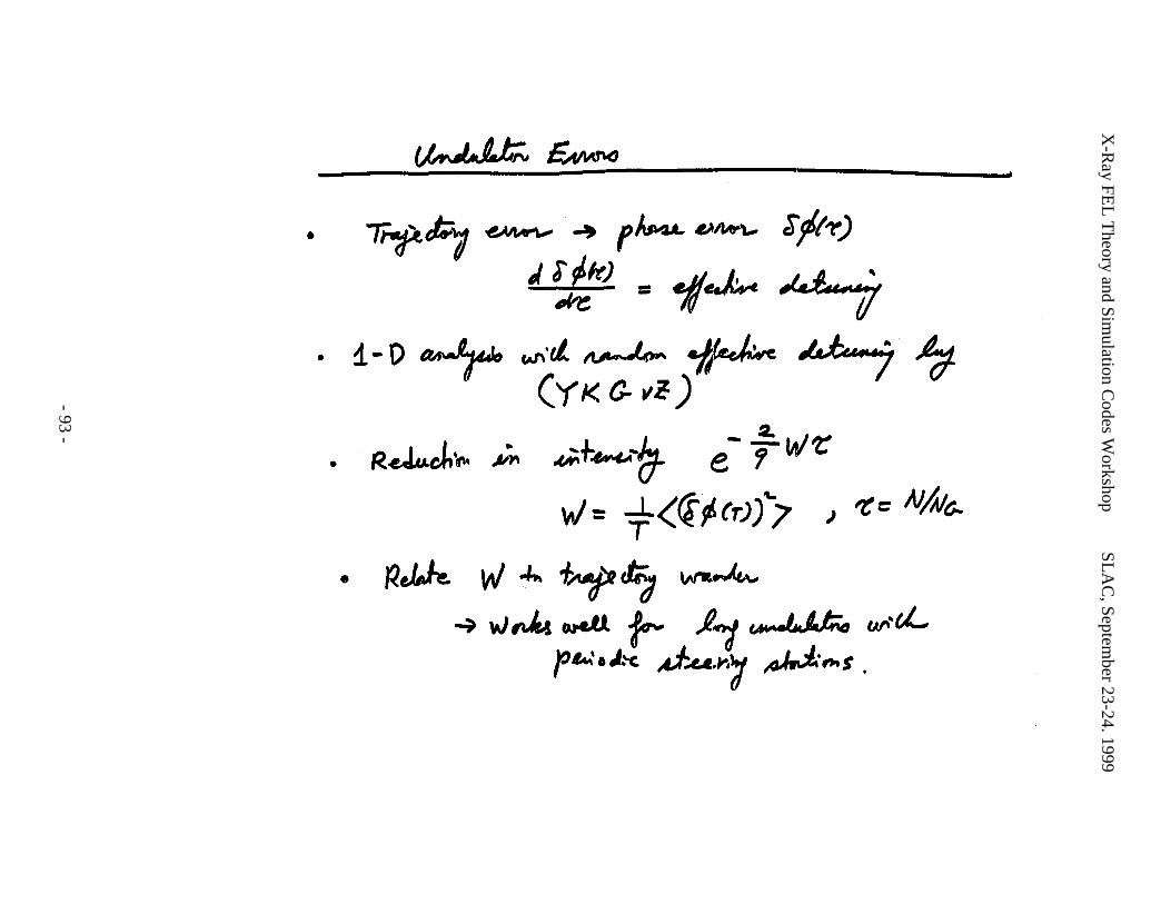
X-R
ay FEL
Theory and Sim
ulation Codes W
orkshopS
LA
C, Septem
ber 23-24. 1999
- 93 -
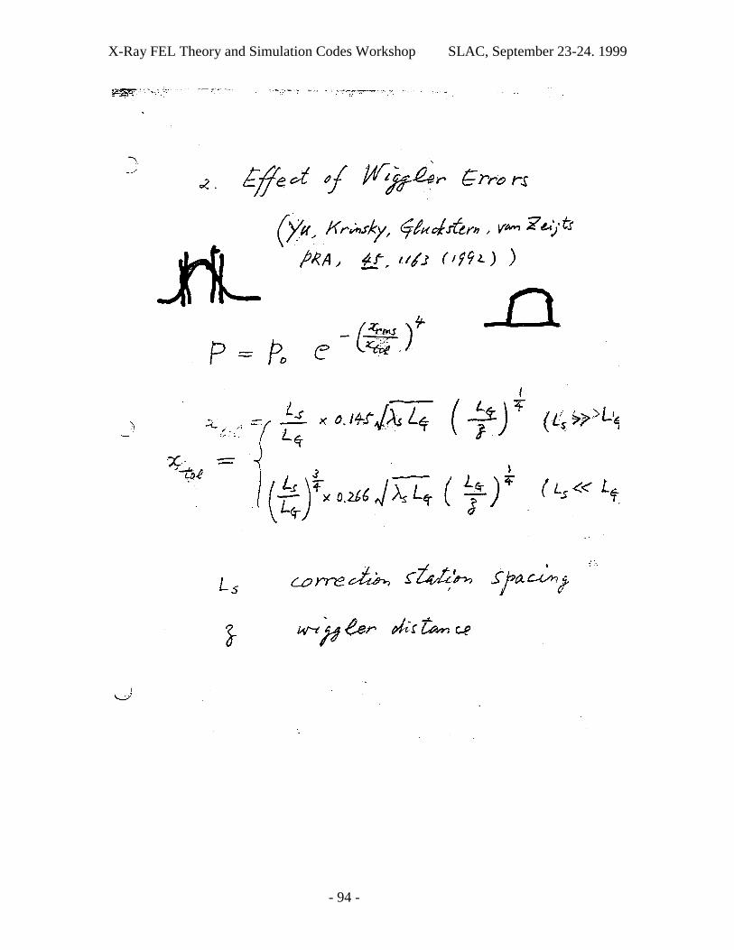
X-Ray FEL Theory and Simulation Codes Workshop SLAC, September 23-24. 1999
- 94 -
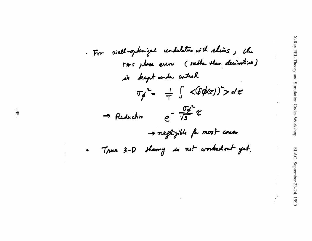
X-R
ay FEL
Theory and Sim
ulation Codes W
orkshopS
LA
C, Septem
ber 23-24. 1999
- 95 -
X-R
ay FEL
Theory and Sim
ulation Codes W
orkshopS
LA
C, Septem
ber 23-24. 1999
- 96 -

X-Ray FEL Theory and Simulation Codes Workshop SLAC, September 23-24. 1999
- 97 -
WORKSHOP PRESENTATIONS IV
3D Analysis of Nonlinear Harmonic GenerationZ. Huang

X-Ray FEL Theory and Simulation Codes Workshop SLAC, September 23-24. 1999
- 98 -
X-R
ay FEL
Theory and Sim
ulation Codes W
orkshopS
LA
C, Septem
ber 23-24. 1999
- 99 -
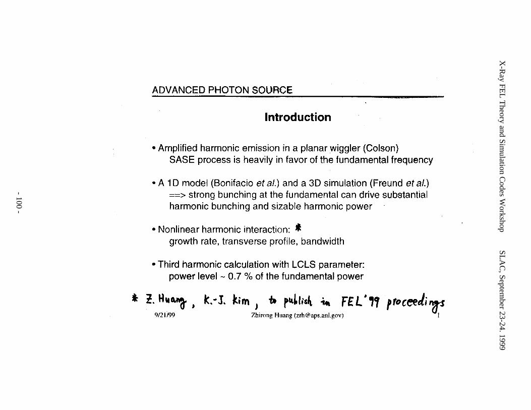
X-R
ay FEL
Theory and Sim
ulation Codes W
orkshopS
LA
C, Septem
ber 23-24. 1999
- 100 -

X-R
ay FEL
Theory and Sim
ulation Codes W
orkshopS
LA
C, Septem
ber 23-24. 1999
- 101 -
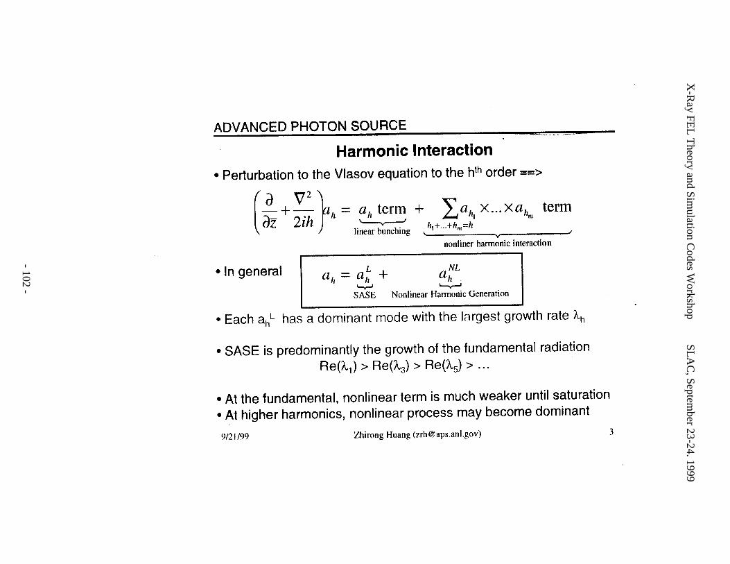
X-R
ay FEL
Theory and Sim
ulation Codes W
orkshopS
LA
C, Septem
ber 23-24. 1999
- 102 -
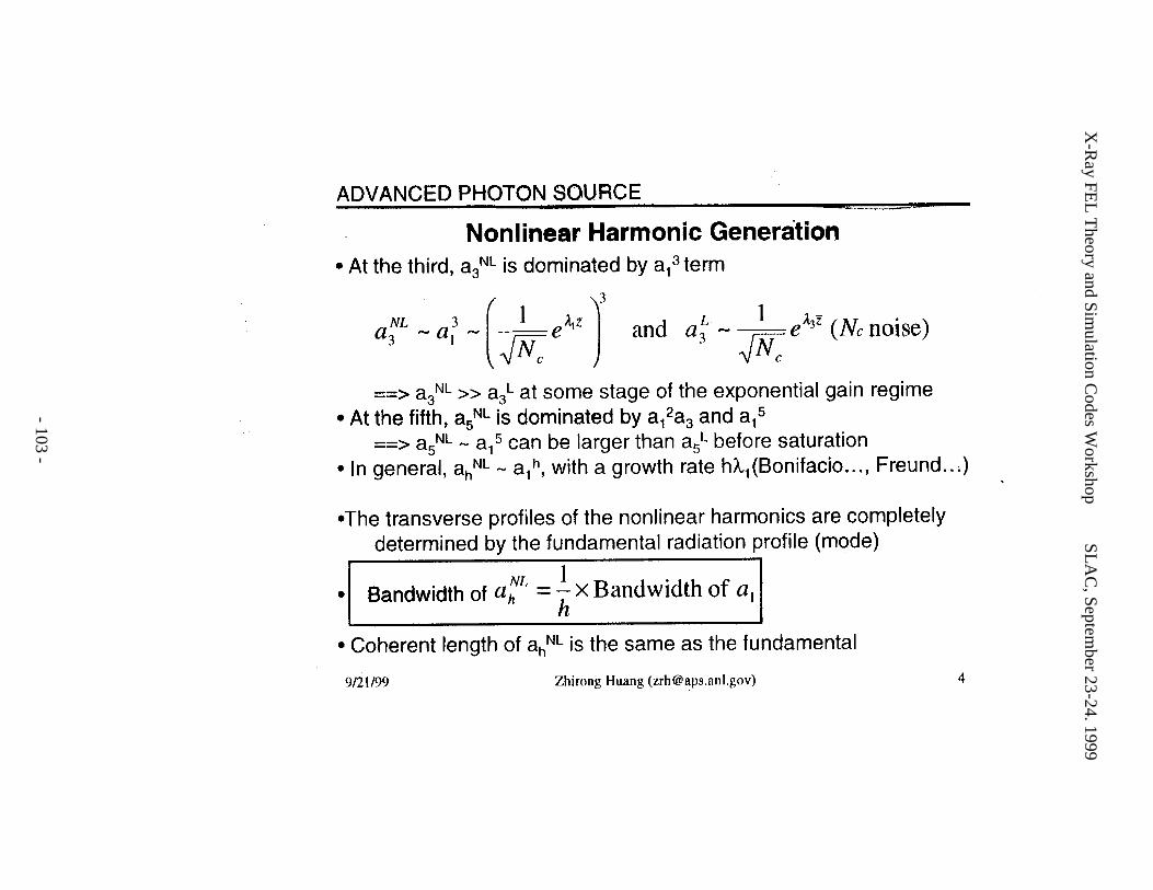
X-R
ay FEL
Theory and Sim
ulation Codes W
orkshopS
LA
C, Septem
ber 23-24. 1999
- 103 -
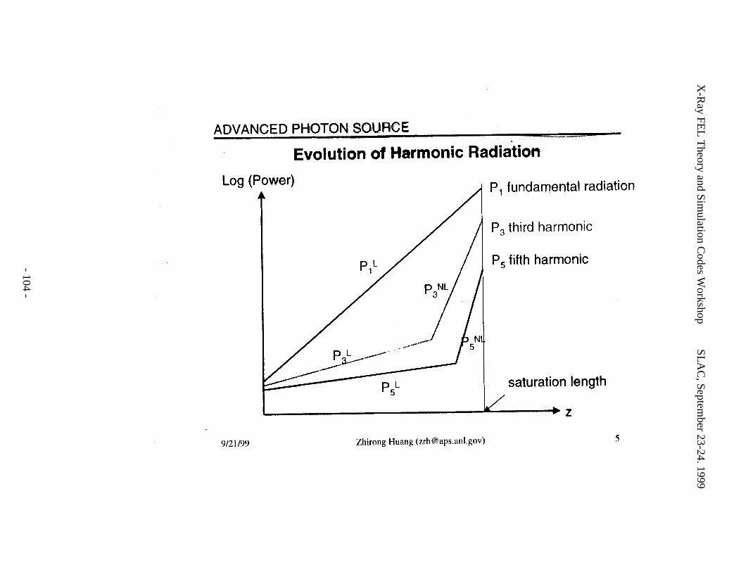
X-R
ay FEL
Theory and Sim
ulation Codes W
orkshopS
LA
C, Septem
ber 23-24. 1999
- 104 -
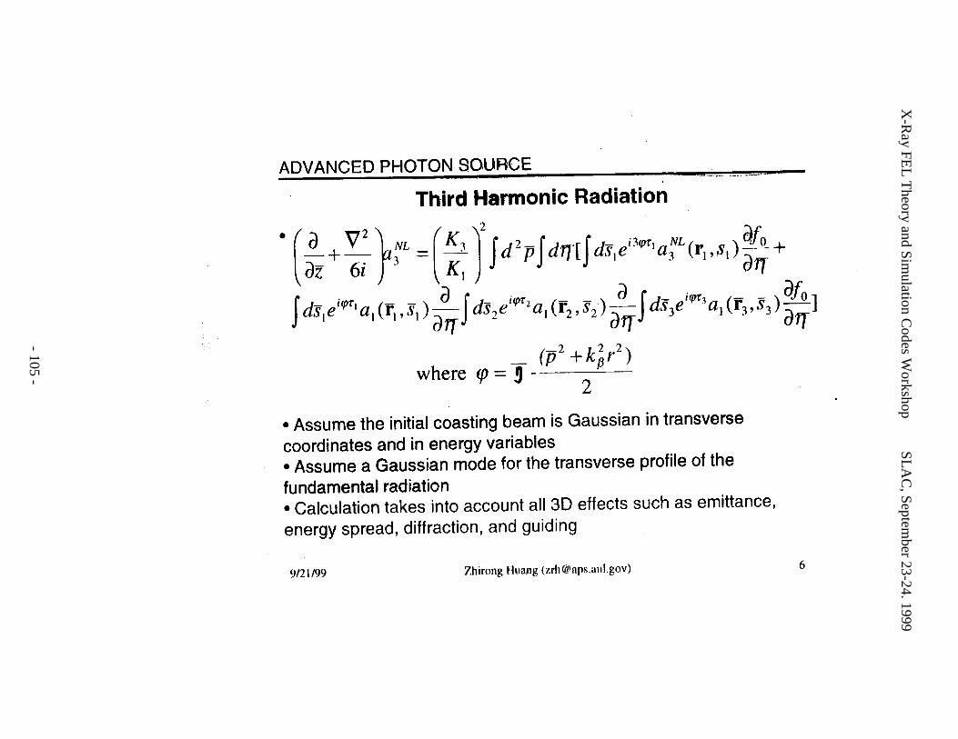
X-R
ay FEL
Theory and Sim
ulation Codes W
orkshopS
LA
C, Septem
ber 23-24. 1999
- 105 -
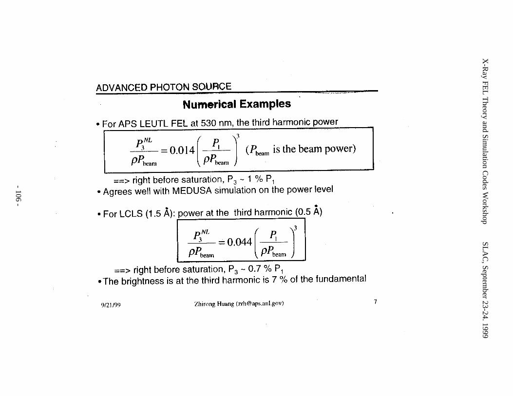
X-R
ay FEL
Theory and Sim
ulation Codes W
orkshopS
LA
C, Septem
ber 23-24. 1999
- 106 -
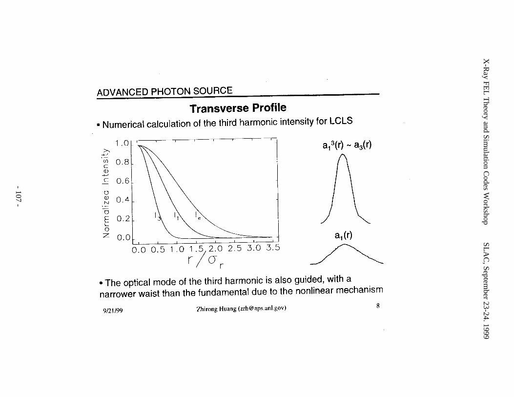
X-R
ay FEL
Theory and Sim
ulation Codes W
orkshopS
LA
C, Septem
ber 23-24. 1999
- 107 -
X-R
ay FEL
Theory and Sim
ulation Codes W
orkshopS
LA
C, Septem
ber 23-24. 1999
- 108 -
X-Ray FEL Theory and Simulation Codes Workshop SLAC, September 23-24. 1999
- 109 -
WORKSHOP PRESENTATIONS V
Exact and Variational Solutions of 3D Eigenmodes for High Gain FELsM. Xie

X-Ray FEL Theory and Simulation Codes Workshop SLAC, September 23-24. 1999
- 110 -
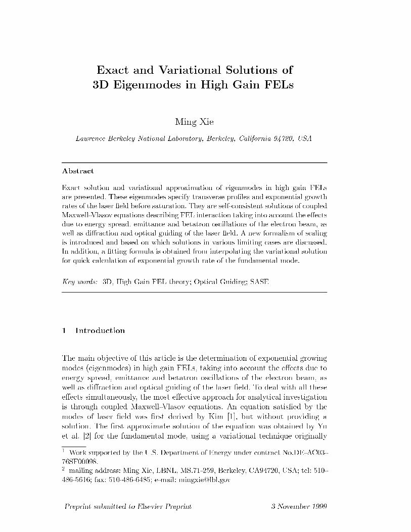
([DFW DQG 9DULDWLRQDO 6ROXWLRQV RI
' (LJHQPRGHV LQ +LJK *DLQ )(/V
0LQJ ;LH
/DZUHQFH %HUNHOH\ 1DWLRQDO /DERUDWRU\ %HUNHOH\ &DOLIRUQLD 86$
$EVWUDFW
([DFW VROXWLRQ DQG YDULDWLRQDO DSSUR[LPDWLRQ RI HLJHQPRGHV LQ KLJK JDLQ )(/V
DUH SUHVHQWHG 7KHVH HLJHQPRGHV VSHFLI\ WUDQVYHUVH SURnOHV DQG H[SRQHQWLDO JURZWK
UDWHV RI WKH ODVHU nHOG EHIRUH VDWXUDWLRQ 7KH\ DUH VHOIFRQVLVWHQW VROXWLRQV RI FRXSOHG
0D[ZHOO9ODVRY HTXDWLRQV GHVFULELQJ )(/ LQWHUDFWLRQ WDNLQJ LQWR DFFRXQW WKH HmHFWV
GXH WR HQHUJ\ VSUHDG HPLWWDQFH DQG EHWDWURQ RVFLOODWLRQV RI WKH HOHFWURQ EHDP DV
ZHOO DV GLmUDFWLRQ DQG RSWLFDO JXLGLQJ RI WKH ODVHU nHOG $ QHZ IRUPDOLVP RI VFDOLQJ
LV LQWURGXFHG DQG EDVHG RQ ZKLFK VROXWLRQV LQ YDULRXV OLPLWLQJ FDVHV DUH GLVFXVVHG
,Q DGGLWLRQ D nWWLQJ IRUPXOD LV REWDLQHG IURP LQWHUSRODWLQJ WKH YDULDWLRQDO VROXWLRQ
IRU TXLFN FDOFXODWLRQ RI H[SRQHQWLDO JURZWK UDWH RI WKH IXQGDPHQWDO PRGH
.H\ ZRUGV ' +LJK *DLQ )(/ WKHRU\ 2SWLFDO *XLGLQJ 6$6(
,QWURGXFWLRQ
7KH PDLQ REMHFWLYH RI WKLV DUWLFOH LV WKH GHWHUPLQDWLRQ RI H[SRQHQWLDO JURZLQJ
PRGHV HLJHQPRGHV LQ KLJK JDLQ )(/V WDNLQJ LQWR DFFRXQW WKH HmHFWV GXH WR
HQHUJ\ VSUHDG HPLWWDQFH DQG EHWDWURQ RVFLOODWLRQV RI WKH HOHFWURQ EHDP DV
ZHOO DV GLmUDFWLRQ DQG RSWLFDO JXLGLQJ RI WKH ODVHU nHOG 7R GHDO ZLWK DOO WKHVH
HmHFWV VLPXOWDQHRXVO\ WKH PRVW HmHFWLYH DSSURDFK IRU DQDO\WLFDO LQYHVWLJDWLRQ
LV WKURXJK FRXSOHG 0D[ZHOO9ODVRY HTXDWLRQV $Q HTXDWLRQ VDWLVnHG E\ WKH
PRGHV RI ODVHU nHOG ZDV nUVW GHULYHG E\ .LP >@ EXW ZLWKRXW SURYLGLQJ D
VROXWLRQ 7KH nUVW DSSUR[LPDWH VROXWLRQ RI WKH HTXDWLRQ ZDV REWDLQHG E\ <X
HW DO >@ IRU WKH IXQGDPHQWDO PRGH XVLQJ D YDULDWLRQDO WHFKQLTXH RULJLQDOO\
:RUN VXSSRUWHG E\ WKH 86 'HSDUWPHQW RI (QHUJ\ XQGHU FRQWUDFW 1R'($&
6) PDLOLQJ DGGUHVV 0LQJ ;LH /%1/ 06 %HUNHOH\ &$ 86$ WHO
ID[ HPDLO PLQJ[LH#OEOJRY
3UHSULQW VXEPLWWHG WR (OVHYLHU 3UHSULQW 1RYHPEHU
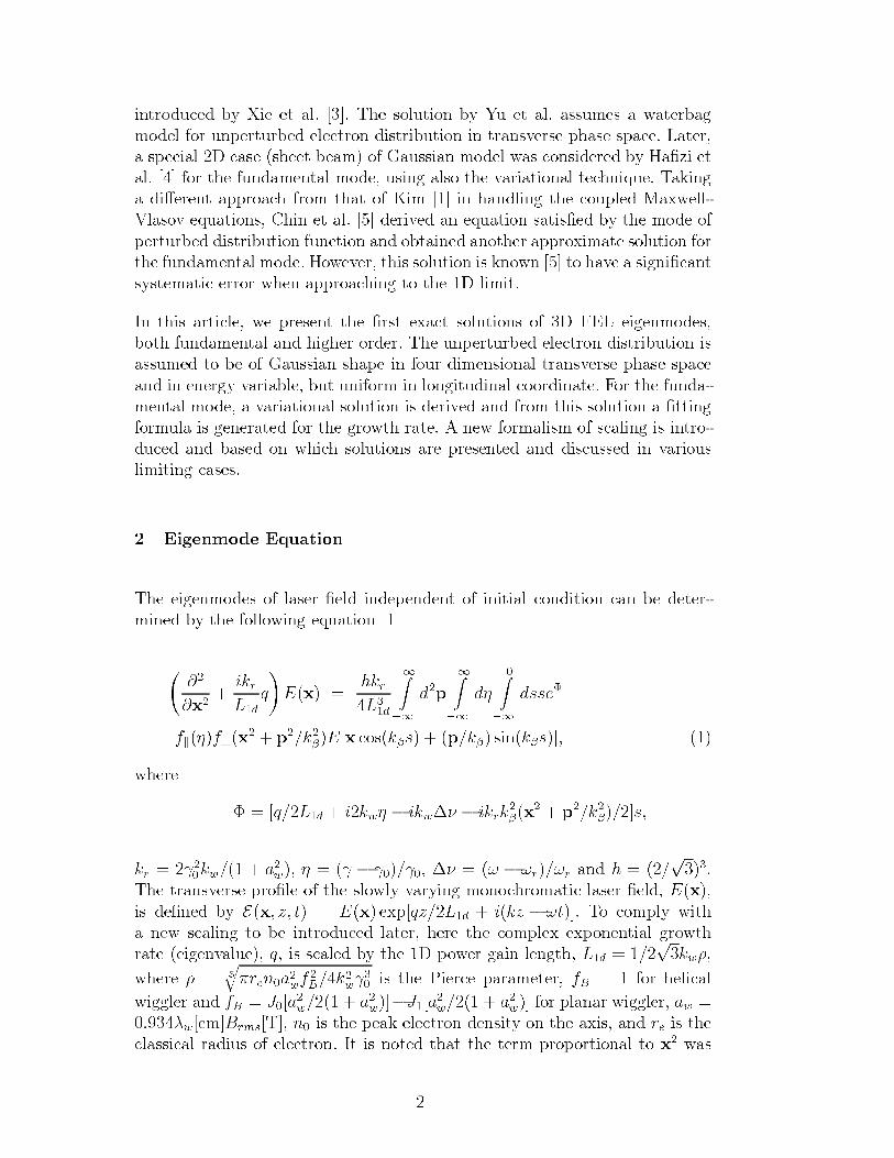
LQWURGXFHG E\ ;LH HW DO >@ 7KH VROXWLRQ E\ <X HW DO DVVXPHV D ZDWHUEDJ
PRGHO IRU XQSHUWXUEHG HOHFWURQ GLVWULEXWLRQ LQ WUDQVYHUVH SKDVH VSDFH /DWHU
D VSHFLDO ' FDVH VKHHW EHDP RI *DXVVLDQ PRGHO ZDV FRQVLGHUHG E\ +Dn]L HW
DO >@ IRU WKH IXQGDPHQWDO PRGH XVLQJ DOVR WKH YDULDWLRQDO WHFKQLTXH 7DNLQJ
D GLmHUHQW DSSURDFK IURP WKDW RI .LP >@ LQ KDQGOLQJ WKH FRXSOHG 0D[ZHOO
9ODVRY HTXDWLRQV &KLQ HW DO >@ GHULYHG DQ HTXDWLRQ VDWLVnHG E\ WKH PRGH RI
SHUWXUEHG GLVWULEXWLRQ IXQFWLRQ DQG REWDLQHG DQRWKHU DSSUR[LPDWH VROXWLRQ IRU
WKH IXQGDPHQWDO PRGH +RZHYHU WKLV VROXWLRQ LV NQRZQ >@ WR KDYH D VLJQLnFDQW
V\VWHPDWLF HUURU ZKHQ DSSURDFKLQJ WR WKH ' OLPLW
,Q WKLV DUWLFOH ZH SUHVHQW WKH nUVW H[DFW VROXWLRQV RI ' )(/ HLJHQPRGHV
ERWK IXQGDPHQWDO DQG KLJKHU RUGHU 7KH XQSHUWXUEHG HOHFWURQ GLVWULEXWLRQ LV
DVVXPHG WR EH RI *DXVVLDQ VKDSH LQ IRXU GLPHQVLRQDO WUDQVYHUVH SKDVH VSDFH
DQG LQ HQHUJ\ YDULDEOH EXW XQLIRUP LQ ORQJLWXGLQDO FRRUGLQDWH )RU WKH IXQGD
PHQWDO PRGH D YDULDWLRQDO VROXWLRQ LV GHULYHG DQG IURP WKLV VROXWLRQ D nWWLQJ
IRUPXOD LV JHQHUDWHG IRU WKH JURZWK UDWH $ QHZ IRUPDOLVP RI VFDOLQJ LV LQWUR
GXFHG DQG EDVHG RQ ZKLFK VROXWLRQV DUH SUHVHQWHG DQG GLVFXVVHG LQ YDULRXV
OLPLWLQJ FDVHV
(LJHQPRGH (TXDWLRQ
7KH HLJHQPRGHV RI ODVHU nHOG LQGHSHQGHQW RI LQLWLDO FRQGLWLRQ FDQ EH GHWHU
PLQHG E\ WKH IROORZLQJ HTXDWLRQ >@
#
#[
LNU
/G
T
([
KNU
/
G
=b
GS
=b
Gs
=b
GVVHj
INsI"[ S N
n(>[ FRVNnV S Nn VLQNnV@
ZKHUH
j >T /G LNZs b LNZcy b LNUN
n[ S N
n @V
NU o
NZ D
Z s o b o o cy b U U DQG K
S
7KH WUDQVYHUVH SURnOH RI WKH VORZO\ YDU\LQJ PRQRFKURPDWLF ODVHU nHOG ([
LV GHnQHG E\ ([ ] W ([ H[S>T] /G LN] b W@ 7R FRPSO\ ZLWK
D QHZ VFDOLQJ WR EH LQWURGXFHG ODWHU KHUH WKH FRPSOH[ H[SRQHQWLDO JURZWK
UDWH HLJHQYDOXH T LV VFDOHG E\ WKH ' SRZHU JDLQ OHQJWK /G SNZ|
ZKHUH |
TUHQDZI
% N
ZoLV WKH 3LHUFH SDUDPHWHU I% IRU KHOLFDO
ZLJJOHU DQG I% ->D
Z D
Z@b->D
Z D
Z@ IRU SODQDU ZLJJOHU DZ
wZ>FP@%UPV>7@ Q LV WKH SHDN HOHFWURQ GHQVLW\ RQ WKH D[LV DQG UH LV WKH
FODVVLFDO UDGLXV RI HOHFWURQ ,W LV QRWHG WKDW WKH WHUP SURSRUWLRQDO WR [ ZDV
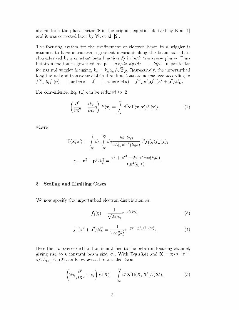
DEVHQW IURP WKH SKDVH IDFWRU j LQ WKH RULJLQDO HTXDWLRQ GHULYHG E\ .LP >@
DQG LW ZDV FRUUHFWHG ODWHU E\ <X HW DO >@
7KH IRFXVLQJ V\VWHP IRU WKH FRQnQHPHQW RI HOHFWURQ EHDP LQ D ZLJJOHU LV
DVVXPHG WR KDYH D WUDQVYHUVH JUDGLHQW LQYDULDQW DORQJ WKH EHDP D[LV ,W LV
FKDUDFWHUL]HG E\ D FRQVWDQW EHWD IXQFWLRQ nI LQ ERWK WUDQVYHUVH SODQHV 7KXV
EHWDWURQ PRWLRQ LV JRYHUQHG E\ S G[ G] GS G] bNn[ ,Q SDUWLFXODU
IRU QDWXUDO ZLJJOHU IRFXVLQJ Nn NZDZ So 5HVSHFWLYHO\ WKH XQSHUWXUEHG
ORQJLWXGLQDO DQG WUDQVYHUVH GLVWULEXWLRQ IXQFWLRQV DUH QRUPDOL]HG DFFRUGLQJ WR5
bGsINs DQG X[ ZKHUH X[
5
bGSI"[
S
Nn
)RU FRQYHQLHQFH (T FDQ EH UHGXFHG WR >@
#
#[
LNU
/G
T
([
=b
G[b[[([
ZKHUH
b[[
=b
GV
=b
GsKNUN
nV
/G VLQ
NnV
HjINsI"
s [ S
Nn [ [
b [c[ FRVNnVVLQ
NnV
6FDOLQJ DQG /LPLWLQJ &DVHV
:H QRZ VSHFLI\ WKH XQSHUWXUEHG HOHFWURQ GLVWULEXWLRQ DV
INs Ss
Hbs s
I"[ S
Nn
[N
n
Hb[S N
n [
+HUH WKH WUDQVYHUVH GLVWULEXWLRQ LV PDWFKHG WR WKH EHWDWURQ IRFXVLQJ FKDQQHO
JLYLQJ ULVH WR D FRQVWDQW EHDP VL]H [ :LWK (TV DQG ; [ [ ~
V /G (T FDQ EH H[SUHVVHG LQ D VFDOHG IRUP
sG
#
#; LT
(;
=b
G;g;;
(;
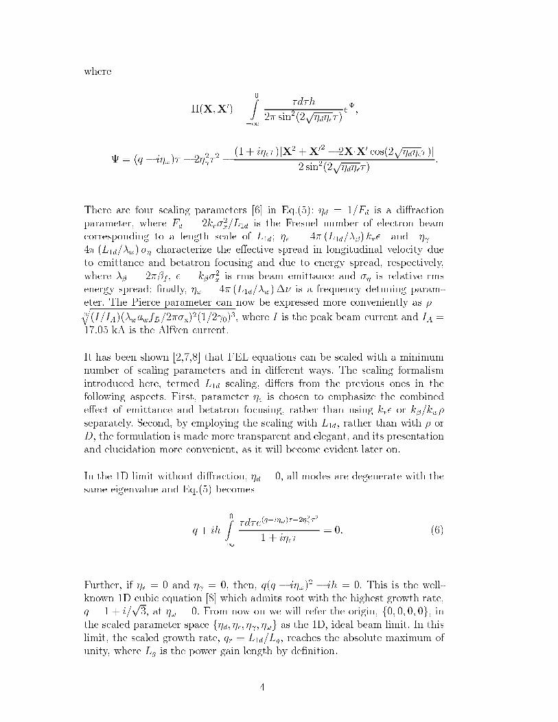
ZKHUH
g;;
=
b
~G~K
VLQSsGsq~
Hk
k T b Ls~ b so~ b
Lsq~ >; ; b ;c; FRV
SsGsq~ @
VLQSsGsq~
7KHUH DUH IRXU VFDOLQJ SDUDPHWHUV >@ LQ (T sG )G LV D GLmUDFWLRQ
SDUDPHWHU ZKHUH )G NU[ /G LV WKH )UHVQHO QXPEHU RI HOHFWURQ EHDP
FRUUHVSRQGLQJ WR D OHQJWK VFDOH RI /G sq /G wn NUq DQG so
/G wZ s FKDUDFWHUL]H WKH HmHFWLYH VSUHDG LQ ORQJLWXGLQDO YHORFLW\ GXH
WR HPLWWDQFH DQG EHWDWURQ IRFXVLQJ DQG GXH WR HQHUJ\ VSUHDG UHVSHFWLYHO\
ZKHUH wn nI q Nn[ LV UPV EHDP HPLWWDQFH DQG s LV UHODWLYH UPV
HQHUJ\ VSUHDG nQDOO\ s /G wZcy LV D IUHTXHQF\ GHWXQLQJ SDUDP
HWHU 7KH 3LHUFH SDUDPHWHU FDQ QRZ EH H[SUHVVHG PRUH FRQYHQLHQWO\ DV |
T, ,$wZDZI% [ o ZKHUH , LV WKH SHDN EHDP FXUUHQW DQG ,$
N$ LV WKH $OItYHQ FXUUHQW
,W KDV EHHQ VKRZQ >@ WKDW )(/ HTXDWLRQV FDQ EH VFDOHG ZLWK D PLQLPXP
QXPEHU RI VFDOLQJ SDUDPHWHUV DQG LQ GLmHUHQW ZD\V 7KH VFDOLQJ IRUPDOLVP
LQWURGXFHG KHUH WHUPHG /G VFDOLQJ GLmHUV IURP WKH SUHYLRXV RQHV LQ WKH
IROORZLQJ DVSHFWV )LUVW SDUDPHWHU sq LV FKRVHQ WR HPSKDVL]H WKH FRPELQHG
HmHFW RI HPLWWDQFH DQG EHWDWURQ IRFXVLQJ UDWKHU WKDQ XVLQJ NUq RU Nn NZ|
VHSDUDWHO\ 6HFRQG E\ HPSOR\LQJ WKH VFDOLQJ ZLWK /G UDWKHU WKDQ ZLWK | RU
' WKH IRUPXODWLRQ LV PDGH PRUH WUDQVSDUHQW DQG HOHJDQW DQG LWV SUHVHQWDWLRQ
DQG HOXFLGDWLRQ PRUH FRQYHQLHQW DV LW ZLOO EHFRPH HYLGHQW ODWHU RQ
,Q WKH ' OLPLW ZLWKRXW GLmUDFWLRQ sG DOO PRGHV DUH GHJHQHUDWH ZLWK WKH
VDPH HLJHQYDOXH DQG (T EHFRPHV
T LK
=
b
~G~HTbLs~bs
o~
Lsq~
)XUWKHU LI sq DQG so WKHQ TT b Ls b LK 7KLV LV WKH ZHOO
NQRZQ ' FXELF HTXDWLRQ >@ ZKLFK DGPLWV URRW ZLWK WKH KLJKHVW JURZWK UDWH
T L
S DW s )URP QRZ RQ ZH ZLOO UHIHU WKH RULJLQ I J LQ
WKH VFDOHG SDUDPHWHU VSDFH IsG sq so sJ DV WKH ' LGHDO EHDP OLPLW ,Q WKLVOLPLW WKH VFDOHG JURZWK UDWH TU s /G /J UHDFKHV WKH DEVROXWH PD[LPXP RI
XQLW\ ZKHUH /J LV WKH SRZHU JDLQ OHQJWK E\ GHnQLWLRQ
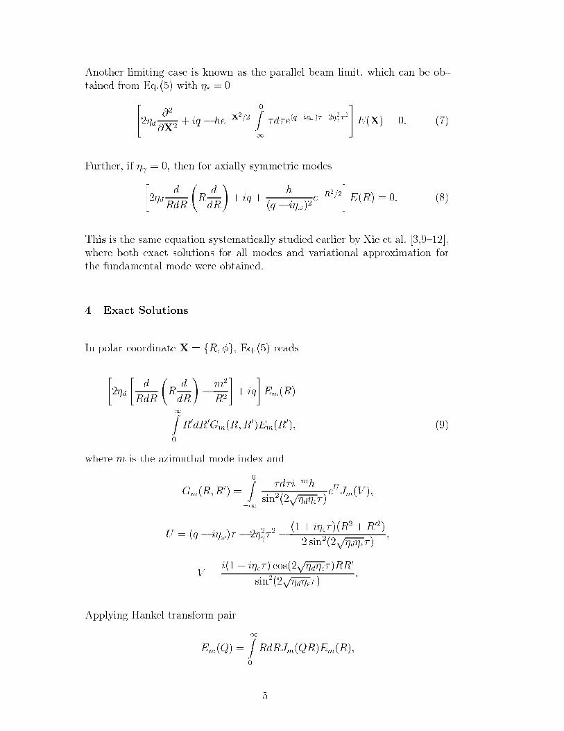
$QRWKHU OLPLWLQJ FDVH LV NQRZQ DV WKH SDUDOOHO EHDP OLPLW ZKLFK FDQ EH RE
WDLQHG IURP (T ZLWK sq
sG #
#; LT b KH
b;
=b
~G~HTbLs~bso~
(;
)XUWKHU LI so WKHQ IRU D[LDOO\ V\PPHWULF PRGHVsG
G
5G5
5
G
G5
LT
K
T b LsHb5
(5
7KLV LV WKH VDPH HTXDWLRQ V\VWHPDWLFDOO\ VWXGLHG HDUOLHU E\ ;LH HW DO >^@
ZKHUH ERWK H[DFW VROXWLRQV IRU DOO PRGHV DQG YDULDWLRQDO DSSUR[LPDWLRQ IRUWKH IXQGDPHQWDO PRGH ZHUH REWDLQHG
([DFW 6ROXWLRQV
,Q SRODU FRRUGLQDWH ; I5J (T UHDGV
sG
G
5G5
5
G
G5
bP
5
LT
(P5
=
5
G5
*P55(P5
ZKHUH P LV WKH D]LPXWKDO PRGH LQGH[ DQG
*P55
=b
~G~LbP
K
VLQSsGsq~
H8-P9
8 T b Ls~ b so~ b
Lsq~ 5 5
VLQSsGsq~
9 L Lsq~ FRV
SsGsq~ 55
VLQSsGsq~
$SSO\LQJ +DQNHO WUDQVIRUP SDLU
(P4
=
5G5-P45(P5
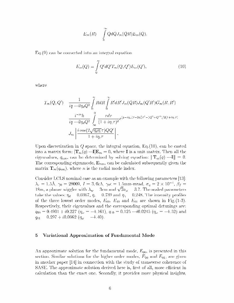
(P5
=
4G4-P45(P4
(T FDQ EH FRQYHUWHG LQWR DQ LQWHJUDO HTXDWLRQ
(P4
=
4G47P44(P4
ZKHUH
7P44
LT b sG4
=
5G5
=
5G5-P45-P45*P55
LbPK
LT b sG4
=b
~G~
Lsq~ HTbLs~bs
o~
b44 Lsq~
-P
L FRV
SsGsq~ 44
Lsq~
8SRQ GLVFUHWL]DWLRQ LQ 4 VSDFH WKH LQWHJUDO HTXDWLRQ (T FDQ EH FDVWHGLQWR D PDWUL[ IRUP >7PTb ,@(P ZKHUH , LV D XQLW PDWUL[ 7KHQ DOO WKHHLJHQYDOXHV TQP FDQ EH GHWHUPLQHG E\ VROYLQJ HTXDWLRQ N7PT b ,N 7KH FRUUHVSRQGLQJ HLJHQPRGH (QP FDQ EH FDOFXODWHG VXEVHTXHQWO\ JLYHQ WKHPDWUL[ 7PTQP ZKHUH Q LV WKH UDGLDO PRGH LQGH[
&RQVLGHU /&/6 QRPLQDO FDVH DV DQ H[DPSOH ZLWK WKH IROORZLQJ SDUDPHWHUV >@wU y$ o , N$ oq PPPUDG s d b nI P D SODQDU ZLJJOHU ZLWK wZ FP DQG
SDZ 7KH VFDOHG SDUDPHWHUV
WDNH WKH YDOXHV sG sq DQG so 7KH LQWHQVLW\ SURnOHVRI WKH WKUHH ORZHVW RUGHU PRGHV ( ( DQG ( DUH VKRZQ LQ )LJ5HVSHFWLYHO\ WKHLU HLJHQYDOXHV DQG WKH FRUUHVSRQGLQJ RSWLPDO GHWXQLQJV DUHT L s b T b L s b DQGT L s b
9DULDWLRQDO $SSUR[LPDWLRQ RI )XQGDPHQWDO 0RGH
$Q DSSUR[LPDWH VROXWLRQ IRU WKH IXQGDPHQWDO PRGH ( LV SUHVHQWHG LQ WKLVVHFWLRQ 6LPLODU VROXWLRQV IRU WKH KLJKHU RUGHU PRGHV ( DQG ( DUH JLYHQLQ DQRWKHU SDSHU >@ LQ FRQQHFWLRQ ZLWK WKH VWXG\ RI WUDQVYHUVH FRKHUHQFH RI6$6( 7KH DSSUR[LPDWH VROXWLRQ GHULYHG KHUH LV nUVW RI DOO PRUH HpFLHQW LQFDOFXODWLRQ WKDQ WKH H[DFW RQH 6HFRQGO\ LW SURYLGHV PRUH SK\VLFDO LQVLJKWV
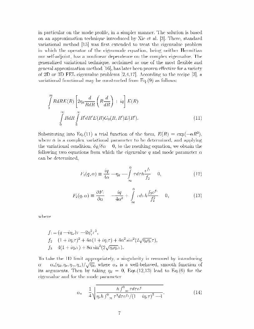
LQ SDUWLFXODU RQ WKH PRGH SURnOH LQ D VLPSOHU PDQQHU 7KH VROXWLRQ LV EDVHG
RQ DQ DSSUR[LPDWLRQ WHFKQLTXH LQWURGXFHG E\ ;LH HW DO >@ 7KHUH VWDQGDUG
YDULDWLRQDO PHWKRG >@ ZDV nUVW H[WHQGHG WR WUHDW WKH HLJHQYDOXH SUREOHP
LQ ZKLFK WKH RSHUDWRU RI WKH HLJHQPRGH HTXDWLRQ EHLQJ QHLWKHU +HUPLWLDQ
QRU VHOIDGMRLQW KDV D QRQOLQHDU GHSHQGHQFH RQ WKH FRPSOH[ HLJHQYDOXH 7KH
JHQHUDOL]HG YDULDWLRQDO WHFKQLTXH DFFODLPHG DV RQH RI WKH PRVW oH[LEOH DQG
JHQHUDO DSSUR[LPDWLRQ PHWKRG >@ KDV ODWHU EHHQ SURYHQ HmHFWLYH IRU D YDULHW\
RI ' RU ' )(/ HLJHQYDOXH SUREOHPV >@ $FFRUGLQJ WR WKH UHFLSH >@ D
YDULDWLRQDO IXQFWLRQDO PD\ EH FRQVWUXFWHG IURP (T DV IROORZV
=
5G5(5
sG
G
5G5
5
G
G5
LT
(5
=
5G5
=
5G5(5*55(5
6XEVWLWXWLQJ LQWR (T D WULDO IXQFWLRQ RI WKH IRUP (5 H[Sbm5
ZKHUH m LV D FRPSOH[ YDULDWLRQDO SDUDPHWHU WR EH GHWHUPLQHG DQG DSSO\LQJ
WKH YDULDWLRQDO FRQGLWLRQ pT pm WR WKH UHVXOWLQJ HTXDWLRQ ZH REWDLQ WKH
IROORZLQJ WZR HTXDWLRQV IURP ZKLFK WKH HLJHQYDOXH T DQG PRGH SDUDPHWHU m
FDQ EH GHWHUPLQHG
)T m sLT
mb sG b
=b
~G~KHI
I
)T m s#)
#m b
LT
m
=b
~G~KIH
I
I
ZKHUH
I T b Ls~ b so~
I Lsq~ m Lsq~ m
VLQSsGsq~
I Lsq~ m VLQSsGsq~
7R WDNH WKH ' OLPLW DSSURSULDWHO\ D VLQJXODULW\ LV UHPRYHG E\ LQWURGXFLQJ
m mVsG sq so s SsG ZKHUH mV LV D ZHOOEHKDYHG VPRRWK IXQFWLRQ RI
LWV DUJXPHQWV 7KHQ E\ WDNLQJ sG (TV OHDG WR (T IRU WKH
HLJHQYDOXH DQG IRU WKH PRGH SDUDPHWHU
mV
YXXW K5
b~G~HI
sqK5
b~ G~HI Lsq~
b
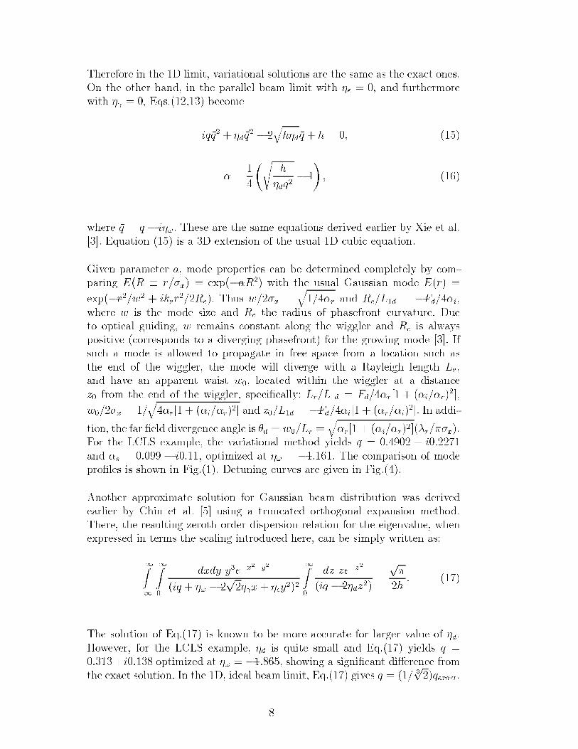
7KHUHIRUH LQ WKH ' OLPLW YDULDWLRQDO VROXWLRQV DUH WKH VDPH DV WKH H[DFW RQHV
2Q WKH RWKHU KDQG LQ WKH SDUDOOHO EHDP OLPLW ZLWK sq DQG IXUWKHUPRUH
ZLWK so (TV EHFRPH
LTxT sGxT b
TKsGxT K
m
VK
sGxTb
ZKHUH xT T b Ls 7KHVH DUH WKH VDPH HTXDWLRQV GHULYHG HDUOLHU E\ ;LH HW DO
>@ (TXDWLRQ LV D ' H[WHQVLRQ RI WKH XVXDO ' FXELF HTXDWLRQ
*LYHQ SDUDPHWHU D PRGH SURSHUWLHV FDQ EH GHWHUPLQHG FRPSOHWHO\ E\ FRP
SDULQJ (5 s U [ H[Sbm5 ZLWK WKH XVXDO *DXVVLDQ PRGH (U
H[SbU Z LNUU 5F 7KXV Z [
T mU DQG 5F /G b)G mL
ZKHUH Z LV WKH PRGH VL]H DQG 5F WKH UDGLXV RI SKDVHIURQW FXUYDWXUH 'XH
WR RSWLFDO JXLGLQJ Z UHPDLQV FRQVWDQW DORQJ WKH ZLJJOHU DQG 5F LV DOZD\V
SRVLWLYH FRUUHVSRQGV WR D GLYHUJLQJ SKDVHIURQW IRU WKH JURZLQJ PRGH >@ ,I
VXFK D PRGH LV DOORZHG WR SURSDJDWH LQ IUHH VSDFH IURP D ORFDWLRQ VXFK DV
WKH HQG RI WKH ZLJJOHU WKH PRGH ZLOO GLYHUJH ZLWK D 5D\OHLJK OHQJWK /U
DQG KDYH DQ DSSDUHQW ZDLVW Z ORFDWHG ZLWKLQ WKH ZLJJOHU DW D GLVWDQFH
] IURP WKH HQG RI WKH ZLJJOHU VSHFLnFDOO\ /U /G )G mU> mL mU@
Z [ TmU> mL mU@ DQG ] /G b)G mL> mU mL
@ ,Q DGGL
WLRQ WKH IDU nHOG GLYHUJHQFH DQJOH LV tG s Z /U TmU> mL mU@wU [
)RU WKH /&/6 H[DPSOH WKH YDULDWLRQDO PHWKRG \LHOGV T L
DQG mV b L RSWLPL]HG DW s b 7KH FRPSDULVRQ RI PRGHSURnOHV LV VKRZQ LQ )LJ 'HWXQLQJ FXUYHV DUH JLYHQ LQ )LJ
$QRWKHU DSSUR[LPDWH VROXWLRQ IRU *DXVVLDQ EHDP GLVWULEXWLRQ ZDV GHULYHG
HDUOLHU E\ &KLQ HW DO >@ XVLQJ D WUXQFDWHG RUWKRJRQDO H[SDQVLRQ PHWKRG
7KHUH WKH UHVXOWLQJ ]HURWK RUGHU GLVSHUVLRQ UHODWLRQ IRU WKH HLJHQYDOXH ZKHQ
H[SUHVVHG LQ WHUPV WKH VFDOLQJ LQWURGXFHG KHUH FDQ EH VLPSO\ ZULWWHQ DV
=b
=
G[G\ \Hb[
b\
LT s b Sso[ sq\
=
G] ]Hb]
LT b sG]
S
K
7KH VROXWLRQ RI (T LV NQRZQ WR EH PRUH DFFXUDWH IRU ODUJHU YDOXH RI sG
+RZHYHU IRU WKH /&/6 H[DPSOH sG LV TXLWH VPDOO DQG (T \LHOGV T
L RSWLPL]HG DW s b VKRZLQJ D VLJQLnFDQW GLmHUHQFH IURPWKH H[DFW VROXWLRQ ,Q WKH ' LGHDO EHDP OLPLW (T JLYHV T
STH[DFW
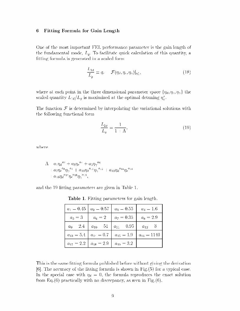
)LWWLQJ )RUPXOD IRU *DLQ /HQJWK
2QH RI WKH PRVW LPSRUWDQW )(/ SHUIRUPDQFH SDUDPHWHU LV WKH JDLQ OHQJWK RI
WKH IXQGDPHQWDO PRGH /J 7R IDFLOLWDWH TXLFN FDOFXODWLRQ RI WKLV TXDQWLW\ D
nWWLQJ IRUPXOD LV JHQHUDWHG LQ D VFDOHG IRUP
/G
/J
s TU )sG sq soMse
ZKHUH DW HDFK SRLQW LQ WKH WKUHH GLPHQVLRQDO SDUDPHWHU VSDFH IsG sq soJ WKH
VFDOHG TXDQWLW\ /G /J LV PD[LPL]HG DW WKH RSWLPDO GHWXQLQJ se
7KH IXQFWLRQ ) LV GHWHUPLQHG E\ LQWHUSRODWLQJ WKH YDULDWLRQDO VROXWLRQV ZLWK
WKH IROORZLQJ IXQFWLRQDO IRUP
/G
/J
e
ZKHUH
e DsGD Dsq
D DsoD
DsqDso
D DsGDso
D DsGDsq
D
DsGDsq
DsoD
DQG WKH nWWLQJ SDUDPHWHUV DUH JLYHQ LQ 7DEOH
7DEOH )LWWLQJ SDUDPHWHUV IRU JDLQ OHQJWK
D D D D
D D D D
D D D D
D D D D
D D D
7KLV LV WKH VDPH nWWLQJ IRUPXOD SXEOLVKHG EHIRUH ZLWKRXW JLYLQJ WKH GHULYDWLRQ
>@ 7KH DFFXUDF\ RI WKH nWWLQJ IRUPXOD LV VKRZQ LQ )LJ IRU D W\SLFDO FDVH
,Q WKH VSHFLDO FDVH ZLWK sG WKH IRUPXOD UHSURGXFHV WKH H[DFW VROXWLRQ
IURP (T SUDFWLFDOO\ ZLWK QR GLVFUHSDQF\ DV VHHQ LQ )LJ
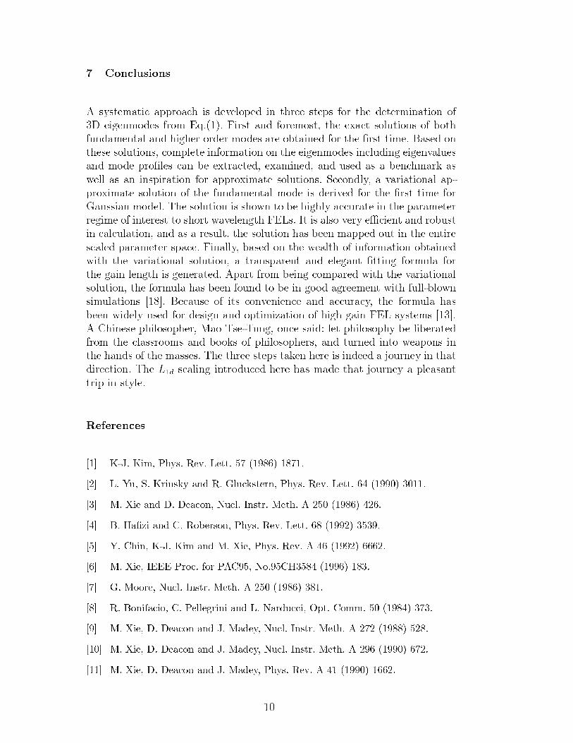
&RQFOXVLRQV
$ V\VWHPDWLF DSSURDFK LV GHYHORSHG LQ WKUHH VWHSV IRU WKH GHWHUPLQDWLRQ RI
' HLJHQPRGHV IURP (T )LUVW DQG IRUHPRVW WKH H[DFW VROXWLRQV RI ERWK
IXQGDPHQWDO DQG KLJKHU RUGHU PRGHV DUH REWDLQHG IRU WKH nUVW WLPH %DVHG RQ
WKHVH VROXWLRQV FRPSOHWH LQIRUPDWLRQ RQ WKH HLJHQPRGHV LQFOXGLQJ HLJHQYDOXHV
DQG PRGH SURnOHV FDQ EH H[WUDFWHG H[DPLQHG DQG XVHG DV D EHQFKPDUN DV
ZHOO DV DQ LQVSLUDWLRQ IRU DSSUR[LPDWH VROXWLRQV 6HFRQGO\ D YDULDWLRQDO DS
SUR[LPDWH VROXWLRQ RI WKH IXQGDPHQWDO PRGH LV GHULYHG IRU WKH nUVW WLPH IRU
*DXVVLDQ PRGHO 7KH VROXWLRQ LV VKRZQ WR EH KLJKO\ DFFXUDWH LQ WKH SDUDPHWHU
UHJLPH RI LQWHUHVW WR VKRUW ZDYHOHQJWK )(/V ,W LV DOVR YHU\ HpFLHQW DQG UREXVW
LQ FDOFXODWLRQ DQG DV D UHVXOW WKH VROXWLRQ KDV EHHQ PDSSHG RXW LQ WKH HQWLUH
VFDOHG SDUDPHWHU VSDFH )LQDOO\ EDVHG RQ WKH ZHDOWK RI LQIRUPDWLRQ REWDLQHGZLWK WKH YDULDWLRQDO VROXWLRQ D WUDQVSDUHQW DQG HOHJDQW nWWLQJ IRUPXOD IRUWKH JDLQ OHQJWK LV JHQHUDWHG $SDUW IURP EHLQJ FRPSDUHG ZLWK WKH YDULDWLRQDOVROXWLRQ WKH IRUPXOD KDV EHHQ IRXQG WR EH LQ JRRG DJUHHPHQW ZLWK IXOOEORZQVLPXODWLRQV >@ %HFDXVH RI LWV FRQYHQLHQFH DQG DFFXUDF\ WKH IRUPXOD KDV
EHHQ ZLGHO\ XVHG IRU GHVLJQ DQG RSWLPL]DWLRQ RI KLJK JDLQ )(/ V\VWHPV >@$ &KLQHVH SKLORVRSKHU 0DR 7VH7XQJ RQFH VDLG OHW SKLORVRSK\ EH OLEHUDWHGIURP WKH FODVVURRPV DQG ERRNV RI SKLORVRSKHUV DQG WXUQHG LQWR ZHDSRQV LQWKH KDQGV RI WKH PDVVHV 7KH WKUHH VWHSV WDNHQ KHUH LV LQGHHG D MRXUQH\ LQ WKDWGLUHFWLRQ 7KH /G VFDOLQJ LQWURGXFHG KHUH KDV PDGH WKDW MRXUQH\ D SOHDVDQW
WULS LQ VW\OH
5HIHUHQFHV
>@ .- .LP 3K\V 5HY /HWW
>@ / <X 6 .ULQVN\ DQG 5 *OXFNVWHUQ 3K\V 5HY /HWW
>@ 0 ;LH DQG ' 'HDFRQ 1XFO ,QVWU 0HWK $
>@ % +Dn]L DQG & 5REHUVRQ 3K\V 5HY /HWW
>@ < &KLQ .- .LP DQG 0 ;LH 3K\V 5HY $
>@ 0 ;LH ,((( 3URF IRU 3$& 1R&+
>@ * 0RRUH 1XFO ,QVWU 0HWK $
>@ 5 %RQLIDFLR & 3HOOHJULQL DQG / 1DUGXFFL 2SW &RPP
>@ 0 ;LH ' 'HDFRQ DQG - 0DGH\ 1XFO ,QVWU 0HWK $
>@ 0 ;LH ' 'HDFRQ DQG - 0DGH\ 1XFO ,QVWU 0HWK $
>@ 0 ;LH ' 'HDFRQ DQG - 0DGH\ 3K\V 5HY $
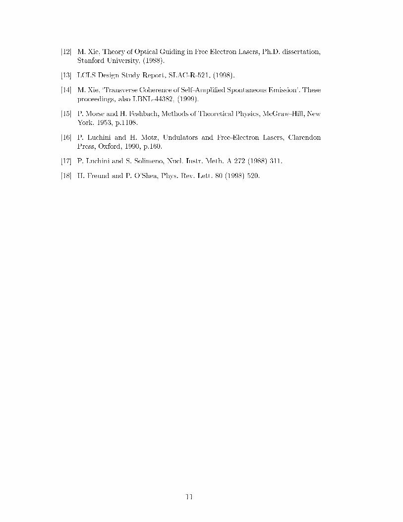
>@ 0 ;LH 7KHRU\ RI 2SWLFDO *XLGLQJ LQ )UHH (OHFWURQ /DVHUV 3K' GLVVHUWDWLRQ6WDQIRUG 8QLYHUVLW\
>@ /&/6 'HVLJQ 6WXG\ 5HSRUW 6/$&5
>@ 0 ;LH C7UDQVYHUVH &RKHUHQFH RI 6HOI$PSOLnHG 6SRQWDQHRXV (PLVVLRQ 7KHVH
SURFHHGLQJV DOVR /%1/
>@ 3 0RUVH DQG + )HVKEDFK 0HWKRGV RI 7KHRUHWLFDO 3K\VLFV 0F*UDZ+LOO 1HZ<RUN S
>@ 3 /XFKLQL DQG + 0RW] 8QGXODWRUV DQG )UHH(OHFWURQ /DVHUV &ODUHQGRQ3UHVV 2[IRUG S
>@ 3 /XFKLQL DQG 6 6ROLPHQR 1XFO ,QVWU 0HWK $
>@ + )UHXQG DQG 3 26KHD 3K\V 5HY /HWW
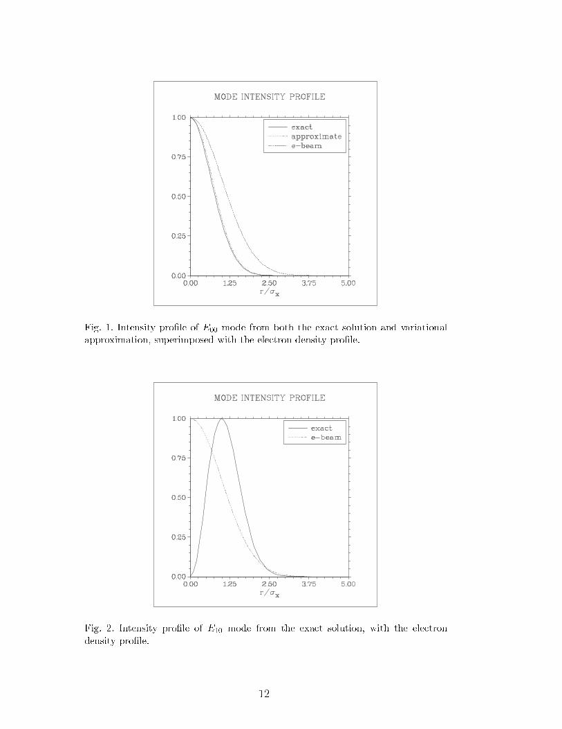
)LJ ,QWHQVLW\ SURnOH RI ( PRGH IURP ERWK WKH H[DFW VROXWLRQ DQG YDULDWLRQDO
DSSUR[LPDWLRQ VXSHULPSRVHG ZLWK WKH HOHFWURQ GHQVLW\ SURnOH
)LJ ,QWHQVLW\ SURnOH RI ( PRGH IURP WKH H[DFW VROXWLRQ ZLWK WKH HOHFWURQ
GHQVLW\ SURnOH
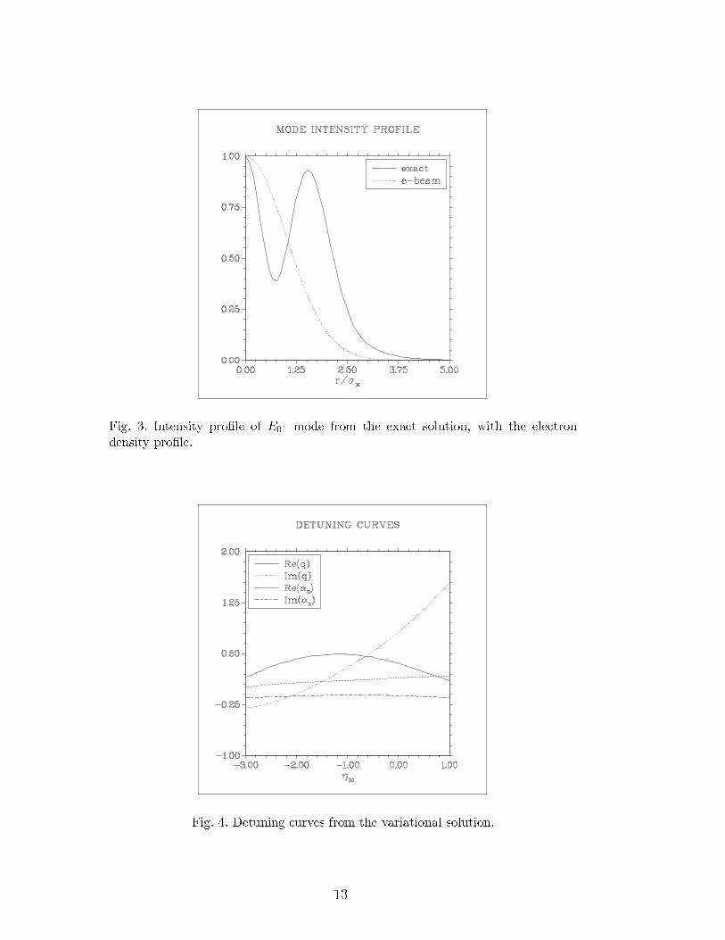
)LJ ,QWHQVLW\ SURnOH RI ( PRGH IURP WKH H[DFW VROXWLRQ ZLWK WKH HOHFWURQ
GHQVLW\ SURnOH
)LJ 'HWXQLQJ FXUYHV IURP WKH YDULDWLRQDO VROXWLRQ
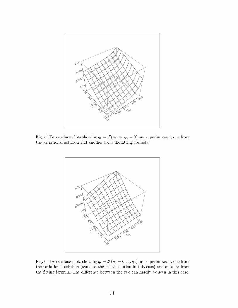
)LJ 7ZR VXUIDFH SORWV VKRZLQJ TU )sG sq so DUH VXSHULPSRVHG RQH IURP
WKH YDULDWLRQDO VROXWLRQ DQG DQRWKHU IURP WKH nWWLQJ IRUPXOD
)LJ 7ZR VXUIDFH SORWV VKRZLQJ TU )sG sq so DUH VXSHULPSRVHG RQH IURP
WKH YDULDWLRQDO VROXWLRQ VDPH DV WKH H[DFW VROXWLRQ LQ WKLV FDVH DQG DQRWKHU IURP
WKH nWWLQJ IRUPXOD 7KH GLmHUHQFH EHWZHHQ WKH WZR FDQ KDUGO\ EH VHHQ LQ WKLV FDVH
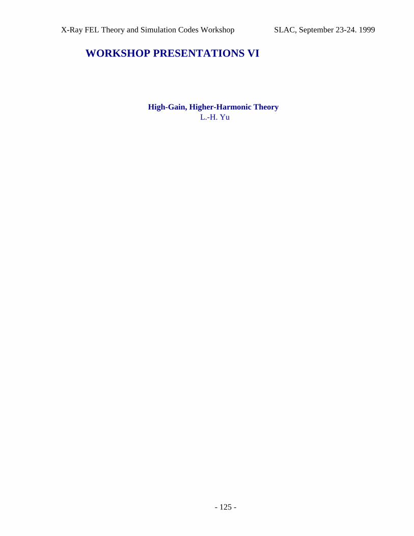
X-Ray FEL Theory and Simulation Codes Workshop SLAC, September 23-24. 1999
- 125 -
WORKSHOP PRESENTATIONS VI
High-Gain, Higher-Harmonic TheoryL.-H. Yu
X-Ray FEL Theory and Simulation Codes Workshop SLAC, September 23-24. 1999
- 126 -
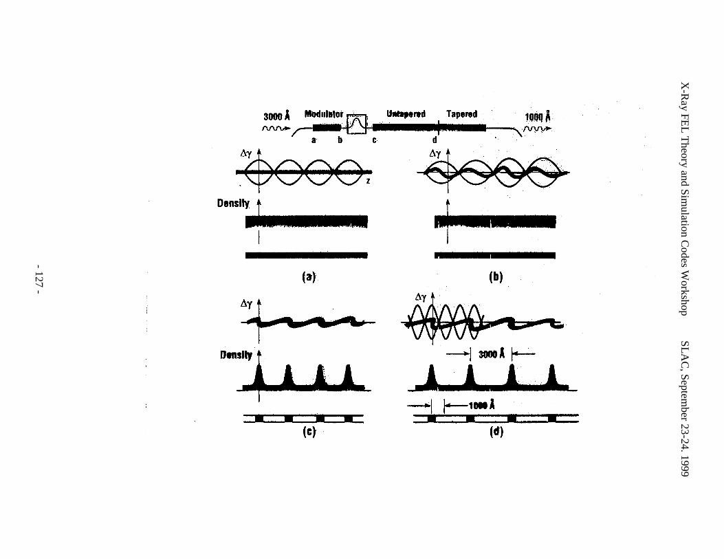
X-R
ay FEL
Theory and Sim
ulation Codes W
orkshopS
LA
C, Septem
ber 23-24. 1999
- 127 -
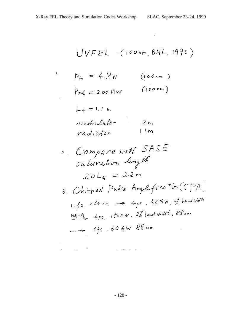
X-Ray FEL Theory and Simulation Codes Workshop SLAC, September 23-24. 1999
- 128 -
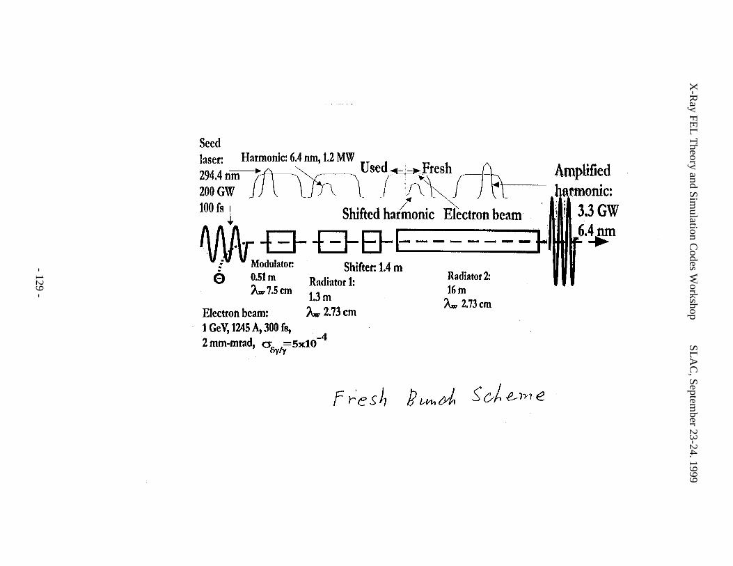
X-R
ay FEL
Theory and Sim
ulation Codes W
orkshopS
LA
C, Septem
ber 23-24. 1999
- 129 -
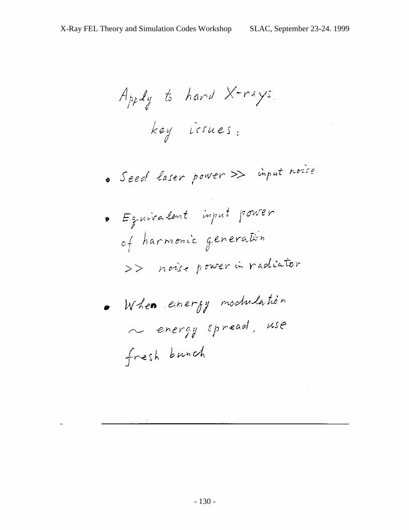
X-Ray FEL Theory and Simulation Codes Workshop SLAC, September 23-24. 1999
- 130 -
X-R
ay FEL
Theory and Sim
ulation Codes W
orkshopS
LA
C, Septem
ber 23-24. 1999
- 131 -
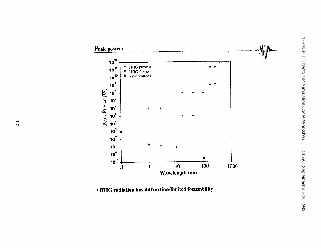
X-R
ay FEL
Theory and Sim
ulation Codes W
orkshopS
LA
C, Septem
ber 23-24. 1999
- 132 -
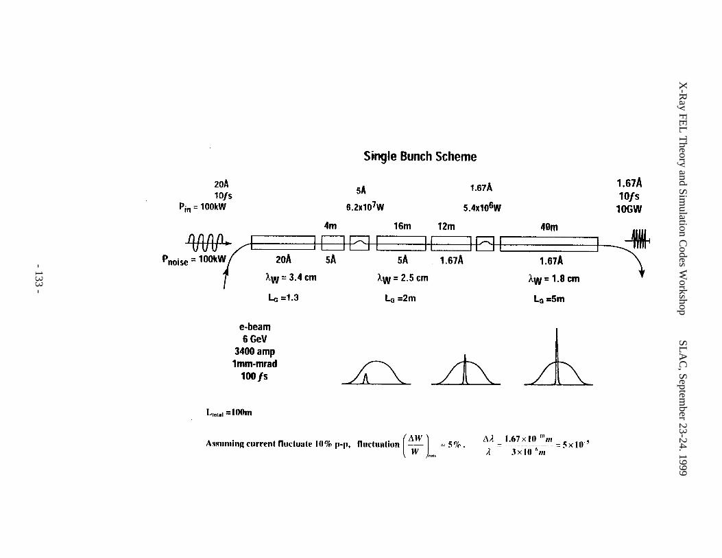
X-R
ay FEL
Theory and Sim
ulation Codes W
orkshopS
LA
C, Septem
ber 23-24. 1999
- 133 -
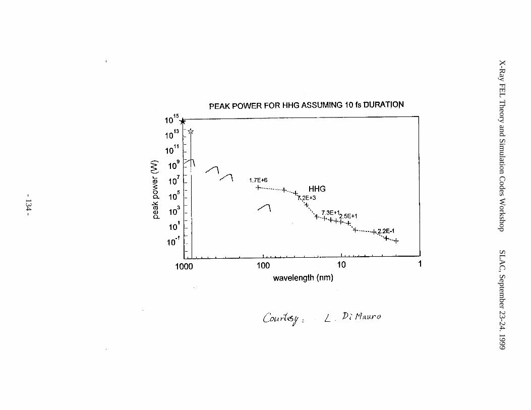
X-R
ay FEL
Theory and Sim
ulation Codes W
orkshopS
LA
C, Septem
ber 23-24. 1999
- 134 -
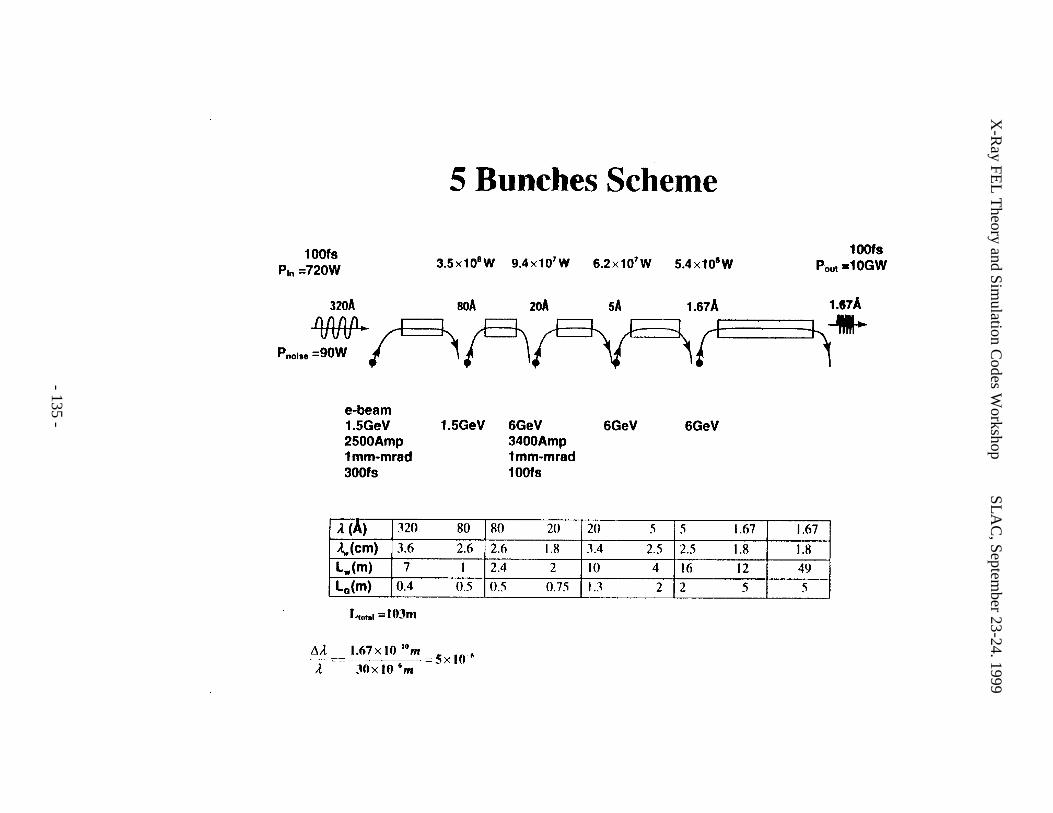
X-R
ay FEL
Theory and Sim
ulation Codes W
orkshopS
LA
C, Septem
ber 23-24. 1999
- 135 -
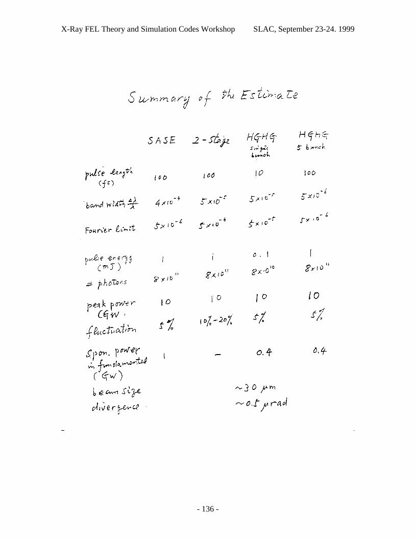
X-Ray FEL Theory and Simulation Codes Workshop SLAC, September 23-24. 1999
- 136 -
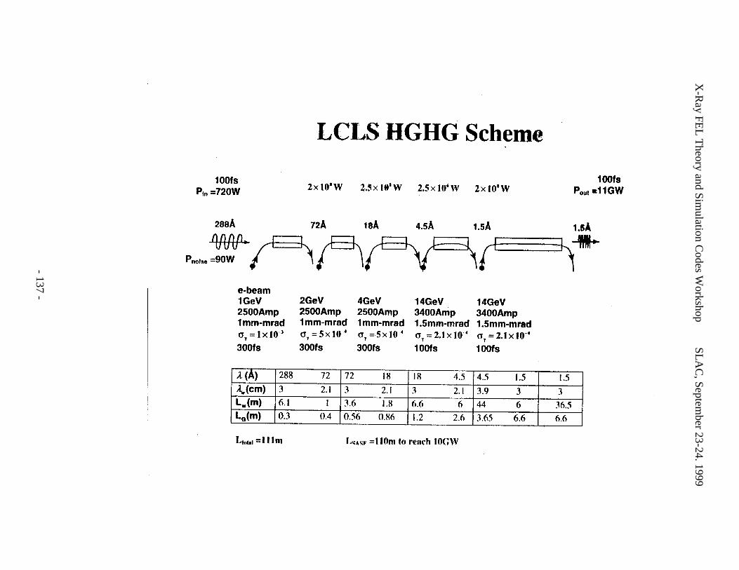
X-R
ay FEL
Theory and Sim
ulation Codes W
orkshopS
LA
C, Septem
ber 23-24. 1999
- 137 -
X-Ray FEL Theory and Simulation Codes Workshop SLAC, September 23-24. 1999
- 138 -
X-Ray FEL Theory and Simulation Codes Workshop SLAC, September 23-24. 1999
- 139 -
WORKSHOP PRESENTATIONS VII
Particle TransportH. Freund

X-Ray FEL Theory and Simulation Codes Workshop SLAC, September 23-24. 1999
- 140 -
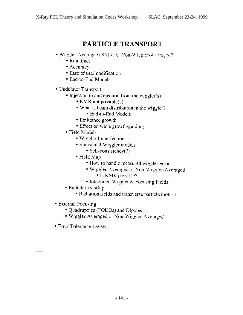
X-Ray FEL Theory and Simulation Codes Workshop SLAC, September 23-24. 1999
- 141 -

X-Ray FEL Theory and Simulation Codes Workshop SLAC, September 23-24. 1999
- 142 -
X-Ray FEL Theory and Simulation Codes Workshop SLAC, September 23-24. 1999
- 143 -
WORKSHOP PRESENTATIONS VIII
Interfacing Multiple Simulation CodesM. Borland

X-Ray FEL Theory and Simulation Codes Workshop SLAC, September 23-24. 1999
- 144 -
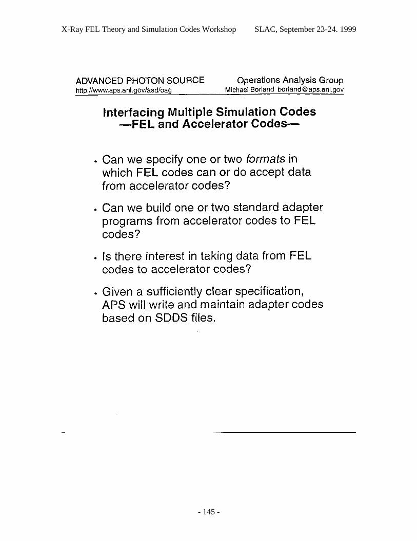
X-Ray FEL Theory and Simulation Codes Workshop SLAC, September 23-24. 1999
- 145 -

X-Ray FEL Theory and Simulation Codes Workshop SLAC, September 23-24. 1999
- 146 -
X-Ray FEL Theory and Simulation Codes Workshop SLAC, September 23-24. 1999
- 147 -
WORKSHOP PRESENTATIONS IX
The High-Gain Harmonic Generation ExperimentS. Biedron
X-Ray FEL Theory and Simulation Codes Workshop SLAC, September 23-24. 1999
- 148 -
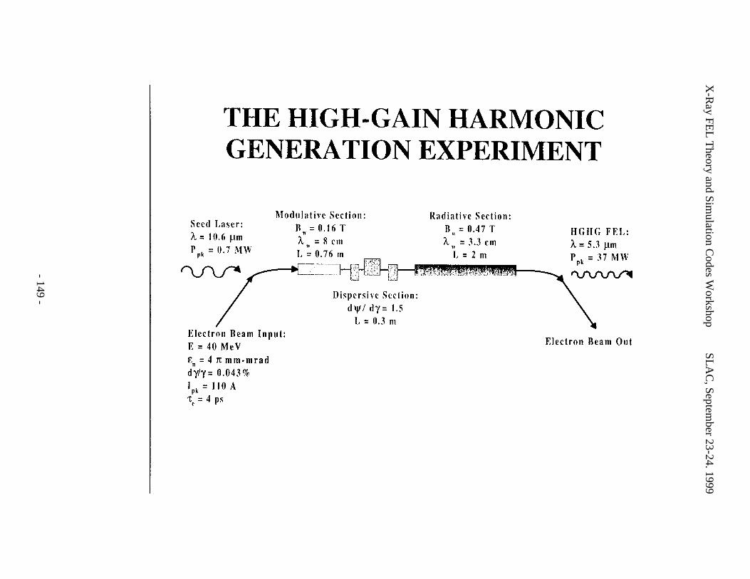
X-R
ay FEL
Theory and Sim
ulation Codes W
orkshopS
LA
C, Septem
ber 23-24. 1999
- 149 -
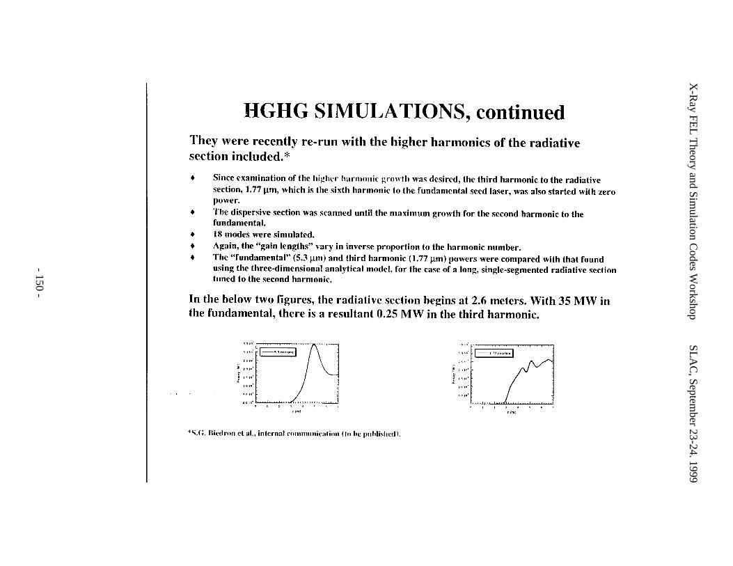
X-R
ay FEL
Theory and Sim
ulation Codes W
orkshopS
LA
C, Septem
ber 23-24. 1999
- 150 -
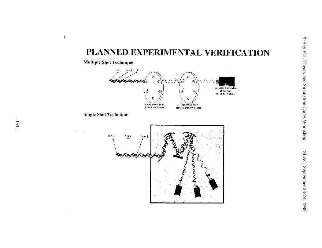
X-R
ay FEL
Theory and Sim
ulation Codes W
orkshopS
LA
C, Septem
ber 23-24. 1999
- 151 -
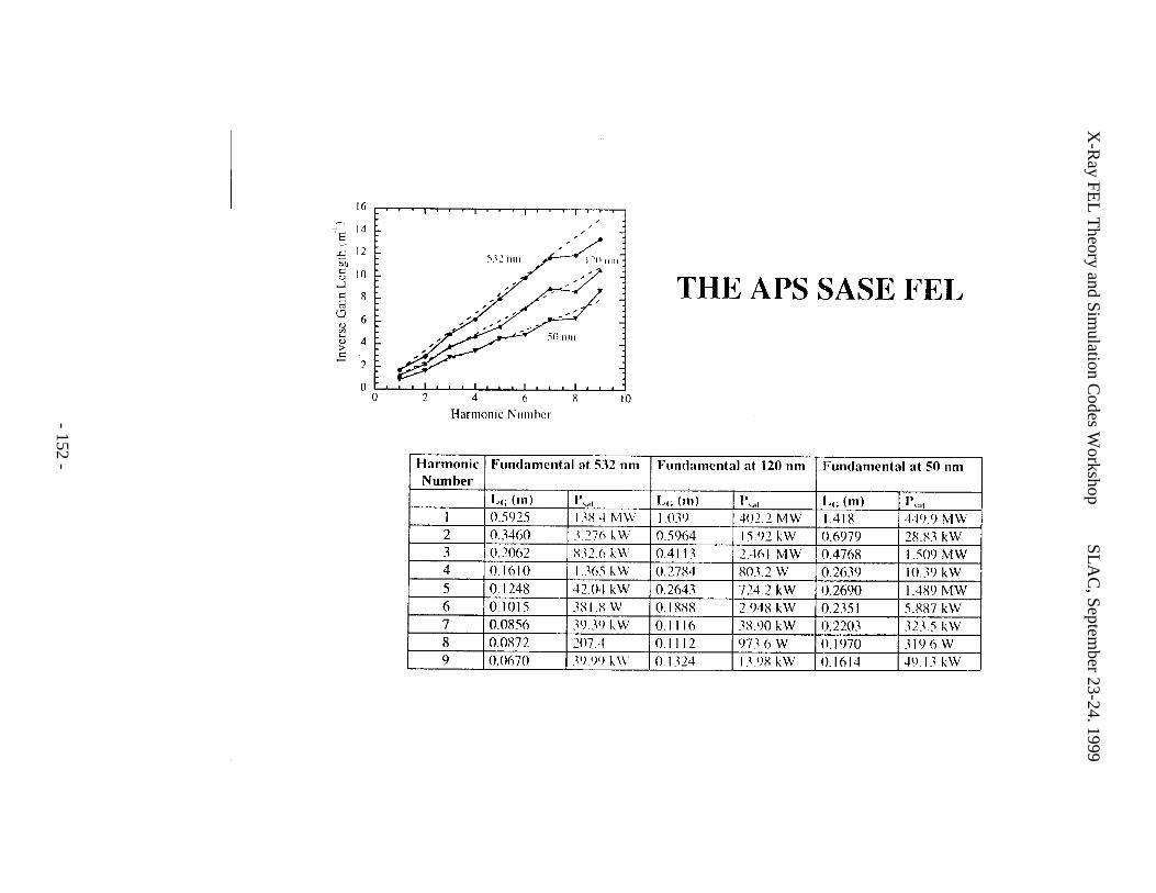
X-R
ay FEL
Theory and Sim
ulation Codes W
orkshopS
LA
C, Septem
ber 23-24. 1999
- 152 -
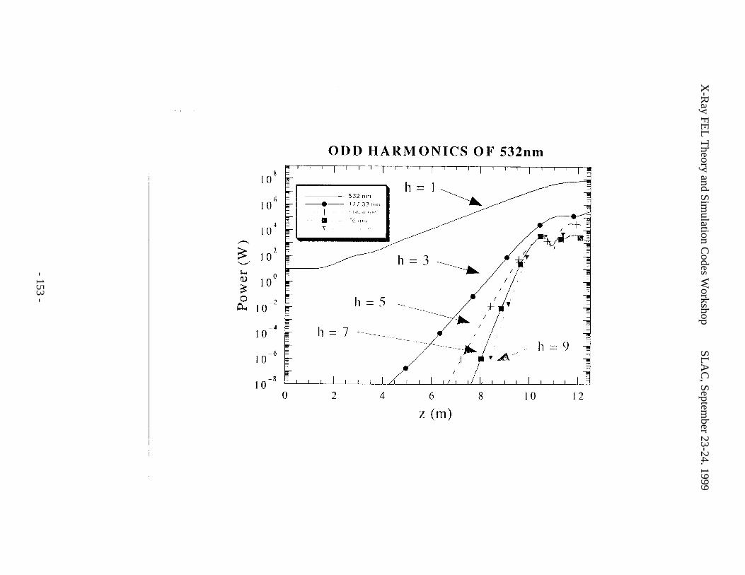
X-R
ay FEL
Theory and Sim
ulation Codes W
orkshopS
LA
C, Septem
ber 23-24. 1999
- 153 -
X-Ray FEL Theory and Simulation Codes Workshop SLAC, September 23-24. 1999
- 154 -
X-Ray FEL Theory and Simulation Codes Workshop SLAC, September 23-24. 1999
- 155 -
APPENDIX A. Synopses of several FEL Simulation Codes
The following pages give extended synopses of the FEL simulation codes MEDUSA,FELEX (both the original LANL version and the modified Boeing version), GENESIS, andGINGER. Each synopsis was written by the code author and/or principal user and additionaldetails can be obtained from them.
X-Ray FEL Theory and Simulation Codes Workshop SLAC, September 23-24. 1999
- 156 -
MEDUSA Simulation Code, Version 2.0H.P. Freund
Science Applications International Corp.McLean, VA 22182
Contact: [email protected] tel.: (202) 767-0034
Code Language: Fortran 77Computer Platforms: Cray, Workstations, Macintosh, PCOperating Systems: Unix, Mac OS, WindowsInputs: Fortran NamelistOutputs: Text files, no graphics capabilities (post-processing required)
Electron Beam/Magnetostatic Fields:
Particle trajectories are solved by integration of the complete 3-D Lorentz forceequations for the magnetostatic and electromagnetic fields. No wiggler averaging isemployed. Three magnetostatic field types are currently implemented:
1. Planar undulators: Three model forms for planar undulators are available. One is aparabolic-pole-face (PPF) model, the second is a flat-pole-face model, and the third is amore complex model with polynomial focusing in the wiggler plane. Each of these modelsis available in single- or multi-segment configurations. Adiabatic up- and down-tapers areavailable for describing the injection onto and ejection from the wiggler. Taperedamplitude undulators are supported.
2. Quadrupoles: The code employs a hard-edge quadrupole model.
3. Dipoles: The dipole model is also a hard-edge representation.
An arbitrary number of each of these field types can be selected, as are the fieldorientations, locations and axial extent of the different magnet segments. The Lorentz forceequations are integrated by calculating the specific magnetic fields at the location of eachparticle.
A version of MEDUSA 1.0 exists in which the magnetostatic fields are specified by afield map that is read in at the start of the program. The field at each particle location is thenfound by interpolating from the field map to each particle location. Such a field map canincorporate the wiggler, quadrupole, and dipole fields into one model. Other types of fieldstructure (such as a FODO lattice) can also be included. If there is sufficient interest, thisfield map/interpolator can be incorporated into MEDUSA 2.0 as well.
X-Ray FEL Theory and Simulation Codes Workshop SLAC, September 23-24. 1999
- 157 -
Wiggler errors are supported, and handled by allowing the wiggler amplitude to varyin arbitrary steps at intervals of some fraction of a wiggler period. The field amplitude atintermediate positions between the steps is determined by a uniform interpolation scheme.The amplitude errors can be generated using a random number generator, or they can behardwired to model a specific set of wiggler errors.
Several electron beam models are available including Gaussian and/or Waterbagbeam distributions, or flat-top beams with circular, elliptic, or sheet (rectangular) cross-sections. Since MEDUSA models beam injection into the wiggler, the parameters of thesedistributions must be chosen to correspond to the beam at the entrance to the wiggler (or atthe exit of the accelerator/transport line). The beam distribution in the wiggler is thenobtained in a self-consistent manner as the beam enters the wiggler.
The Radiation Field
The radiation field is fully polychromatic and is represented as a superposition ofGauss-Hermite modes in which the amplitude and phase are assumed to vary more slowlythan the wavelength. Slow-time-scale equations for the evolution of the amplitudes andphases are then integrated simultaneously with the Lorentz force equations. A source-dependent expansion is also used to determine the evolution of the spot size and curvature ofthe Gauss-Hermite modes. This reduces the number of modes needed in the simulation, anddramatically reduces the run times.
MEDUSA includes multiple wavelengths under the assumption that each componentoccurs at a frequency that is a multiple of some reference frequency ω0. This spectralapproach permits the treatments of either closely-spaced sidebands or harmonics. Thus,MEDUSA can treat the simultaneous growth of multiple harmonics or the startup from noisein a SASE FEL. However, the polychromatic feature requires the inclusion of a largernumber of particles (than the monochromatic case) that results in longer run times.
Numerical Algorithm
A fourth order Runge-Kutta integration scheme is used to integrate the combinedfield and particle equations. The particles are loaded at the outset based upon the initialparticle distributions using a Gaussian quadrature technique. This technique has theadvantage that it implicitly describes a “quiet-start” load that minimizes both particle numberand numerical noise.
Diagnostics
MEDUSA produces no graphical output, this is left up to the user. The principaloutput is a file that records header information on the beam wiggler/focussing magnets, andelectromagnetic modes followed by a listing of the evolution of each mode with axialposition. The modes are listed sequentially, and columns showing the axial position, power(W), spot size (cm), and curvature are given. In addition, the first mode also shows the rms
X-Ray FEL Theory and Simulation Codes Workshop SLAC, September 23-24. 1999
- 158 -
beam radius and number of particles in the simulation. A file is also written which shows theevolution of the beam centroid in x and y, the average width about the centroid in x and y,and the rms beam radius. The beam state (that is x, y, px, py, pz, and the ponderomotive phasefor each particle) can also be written to a file at selected axial positions. These text files arewritten in a form which is convenient for commercially available plotting packages (such asKaleidagraph, Sigma Plot, Igor, etc.) to handle.
X-Ray FEL Theory and Simulation Codes Workshop SLAC, September 23-24. 1999
- 159 -
FELEX - LANL versionJohn C. Goldstein
Group XPA, MS B259Los Alamos National LaboratoryLos Alamos, New Mexico 87545
Contact: [email protected] tel.: 505-667-7281
FELEX (Free-Electron Laser Emulation eXperiment) is a 4-D (three spatialdimensions plus time for finite-duration optical and electron beam pulses) FEL simulationcode written by B. D. McVey of LANL [1]. The original motivation (1984) for writing thecode was to address problems of XUV FEL oscillators, but about one year after its beginningthe work became sponsored by the SDI program at LANL. Over the next several years thecode was expanded to treat many different specialized FEL problems [2,3], and, although thecoding was primarily still composed by McVey, several other people made contributions tothe code.
The code uses discrete, pointlike simulation "macro"-electrons (which havecoordinates and velocities in 3-D) to represent an electron beam. Fields, magnetostatic(wiggler) and electromagnetic (optical), are computed on a 3-D grid composed of uniformly-spaced Cartesian coordinates. Within the wiggler region of an FEL, the simulation electronsinteract with the wiggler and optical fields via classical Lorentz force equations whichassume slow - compared to a wiggler wavelength - variations of the electrons’ motionsuperimposed on the undulator-induced rapid transverse oscillations; the narrow-bandwidthoptical field is represented by slowly-varying phase and amplitude functions which modulatethe rapidly-varying sinusoidal phase function of a monochromatic carrier signal. All field andparticle variables are allowed to vary in 3-D; transverse diffraction and refraction of theoptical field are included. Together with slippage (the different axial velocities of the electronbeam within the wiggler and the optical field) these assumptions follow the general FELmodel introduced by Colson and Ride in 1979.
The code was constructed to primarily model FEL oscillators, therefore extensivemodels of optical components and resonators are included: these range from simple two-mirror stable resonators to multiple-mirror ring resonators with complex optical componentslike diffraction gratings. Mirror aberrations can be treated. The code uses the Huygens-Fresnel diffraction integral, evaluated by fast Fourier transforms, to propagate the opticalfield in spatial regions outside of the wiggler where free-space propagation alone occurs. Theoptical field generated by an FEL can be propagated through an optical system external to thelaser itself. Misalignments of optical components can also be treated.
X-Ray FEL Theory and Simulation Codes Workshop SLAC, September 23-24. 1999
- 160 -
Various types of wiggler magnets can be used, including "self-designed" wigglers inwhich a pre-programmed "resonant particle" defines the nonuniform taper. Since theelectrons’ equations of motion do not follow trajectories within an individual wigglerwavelength, an instantaneous transverse deflection ("kick") is given to electrons every halfperiod to model steering errors due to wiggler field errors. Various schemes of trajectorycorrection involving periodically-spaced localized external steering coils and (imperfect)beam position monitors have been extensively studied with FELEX. The code presently is setup to use only plane-polarized wigglers with either "natural" or two-plane focusing.
Electron shot noise is modeled for startup calculations. An auxiliary code was writtento permit FELEX to input directly electron distributions calculated by the acceleratordesign/modeling code PARMELA. FELEX can be run with a single optical wavefront (CWsingle-frequency model), a temporally-finite pulse (which of course requires also a finiteelectron pulse), or with periodic boundary conditions on an optical "window" which typicallyis several slippage distances long - an approximation introduced by Colson. The optical fieldneed not be at the fundamental FEL resonance frequency - any odd harmonic can be chosen,but multiple harmonic fields which are simultaneously present are not treated. Oscillatorsimulations require many passes through a wiggler with a recirculating optical pulseinteracting with fresh electron pulses on each pass; single pass SASE FEL simulations aretherefore much less consuming of computer time.
References
[1] B. D. McVey, Nucl. Instr. Meth. in Phys. Res., A250, pp. 449-455 (1985).
[2] J. C. Goldstein, B. D. McVey, R. L. Tokar, C. J. Elliott, M. J. Schmitt, B. E. Carlsten, andL. E. Thode, Proc. SPIE vol. 1045, pp. 28-35 (1989).
[3] B. D. McVey, J. C. Goldstein, R. L. Tokar, C. J. Elliott, S. J. Gitomer, M. J. Schmitt, andL. E. Thode, Nucl. Instr. Meth. in Phys. Res., A285, pp. 186-191 (1989).
X-Ray FEL Theory and Simulation Codes Workshop SLAC, September 23-24. 1999
- 161 -
FELEXN, Boeing simulation code, version B08
Claudio G. ParazzoliBoeing, Phantom Works
P.O. Box 3999 MC 85-02Seattle, WA 98124-2499
Contact: [email protected] tel.: 253-773-8299
FELEXN is a three-dimensional and time dependent computer code that computes theFEL performance from the phase space of the electron bunch, computed with the help ofARGUS, PARMELA and ABCI, at the entrance of a wiggler. This code has also beenextensively modified from the original LANL version, written by B. McVey, to allow for thepresence of Littrow-Gratings, hole coupling and the corrections of numerous coding errors.An interface between PARMELA and FELEXN has been created to transfer the phase spacegenerated by PARMELA into FELEXN.
The code is currently being ported to Fortran90/95 to improve the CPU performanceand runs on UNIX systems including Sun, HP and DEC workstations. The code integratesthe FEL equations using the KMR (averaging) method and adopts the Slowly VaryingEnvelope Approximation (SVEA) to advance the optical field. Wiggler errors are includedwith the impulse being applied at mid pole.
FELEXN has the ability to operate in the amplifier or oscillator mode. The opticaltrain for the amplifier or oscillator can include an arbitrary number of optical elementsincluding mirrors, lenses, scrapers, apertures, out-couplers, etc. The optical field ispropagated between optical elements via Fresnel integrals. The code operates in the singlewave-front (i.e. monochromatic) mode when the temporal dependence of the pulse can beignored and no information on the frequency spectrum is required. There is no restriction onthe type of spatial optical modes that will be generated by the lasing process. A transverseCartesian grid resolution of 64 ×64 or 128 ×128 pixels is usually adequate.
The optical radiation field is initiated either by shot noise or by a seed. The code canoperate at different harmonics, but there is no coupling mechanism between harmonics. Intime-dependent mode, the code can follow as many as 300 wave fronts, which usuallyprovide a sufficient spectral resolution. Periodic boundary conditions are allowed. Foroscillator simulations, laser cavity detuning is allowed and can be time-dependent.
An extensive post processing capability is available with many different types of twoand three-dimensional plots being generated at the user request. Currently, MatLab is used togenerate the plots and the pictures.
A number of improvements to the code are currently planned: the addition of thebeam pipe effects on the optical field, wake-field effects within the wiggler, relaxation of theKMR assumption, porting to multi-processor machines, extension of the internaldocumentation, and the writing of an user manual.
X-Ray FEL Theory and Simulation Codes Workshop SLAC, September 23-24. 1999
- 162 -
GENESIS 1.3 Simulation CodeS. Reiche, DESY (contribution translated by H.-D. Nuhn, SSRL)
Contact: [email protected]
The Electron Beam
Transverse Motion: Analytical transport matrices are used for x, y, px, py. Inputparameter is the instantaneous focusing strength, i.e,. the quadrupole field, g, and the naturalfocusing by the undulator field, aw. The parameters g and aw can be freely defined for eachintegration step (see below), A kick in px (and py for helical undulators) is used to simulateundulator errors or quadrupole misalignments. The kick due to field errors is calculated fromthe continuity condition between two undulator poles, if a phase advance of π per pole isassumed. Quadrupole misalignments are treated like dipole field errors. To increase theprecision, the transverse motion is expanded into two steps, before and after the calculationof energy and phase.
Longitudinal Motion: The code uses a fourth order Runge-Kutta method. If aw is zerofor a given integration step, the coupling term between the electrons and the field is set tozero. This corresponds to a drift in phase and to a constant energy.
Additional Effects: The increase of energy spread and energy loss due to incoherentradiation is included. The formulae are based on a paper by Saldin, Schneidmiller andYurkov. This feature has been added to the next version of GENESIS, which is still notofficial.
An arbitrary selectable energy loss per path length is included in the code. Thisfeature allows to simulate wakefields. Further extensions to the code are conceivable.
The Radiation Field
The radiation field is defined on a uniform Cartesian grid. The field equations aresolved with the ADI method (Alternating Direction Implicit). The electrostatic field isevaluated with a radially symmetric grid, that is centered around the electron bunch. Theboundary condition corresponds to a Dirichlet condition. This is relatively inefficient and Ihope that I will be able to replace it in the next version by a faster method (A multi-gridmethod is conceivable, because it would also be highly efficient for solving the radiationfield equations.)
Diagnostics
Electron and radiation parameters such as energy, bunching factor, radiation powerand instantaneous divergence of the radiation field are put out for every integration step. Theoutput is in ASCII format. Additionally, the complete radiation field and all macro particlevariables can be saved to disk for each simulation time step. The output of these data is inbinary format.
X-Ray FEL Theory and Simulation Codes Workshop SLAC, September 23-24. 1999
- 163 -
Input
The Fortran Namelist feature is used for input of a good four dozen parameters. Fromthese parameters, which are mostly global parameters, i.e., independent of the longitudinalposition within the bunch, the initial phase space distribution and the radiation field aregenerated. The bunch profile, i.e., the local current amplitude, is either homogeneous orGaussian. All other electron beam parameters are global. The initial radiation field is alwaysa Hermite fundamental mode. The description of the magnetic field generates a FODO-Lattice, where focusing and defocusing quadrupoles can be described independently. Anundulator module, whose length can be freely chosen, is padded with drift spaces before orafter (freely selectable) the module to make the total length equal to an integer multiple of theFODO cell length. Quadrupole misalignment errors and field errors can be generated.
Additional input files, which extend the input capability:
Field: An arbitrary distribution on the Cartesian grid can be used instead of the internallygenerated Hermite distribution.
Magnetic Field: Undulator field strengths, quadrupole field strengths, kicks from fielderrors, quadrupole misalignments and kicks from corrector magnets can be specified in aninput file for arbitrary sections.
Electron Beam: Electron beam parameters are specified in a lookup table. The first entry inthe table is the longitudinal position, which is followed by electron parameters such asenergy, emittance, local current amplitude and local energy loss. The latter allows thespecification of wake potentials and thus the simulation of wakefields. When GENESISgenerates the electron slices it interpolates between values from this table. With this, anyprofile including a coherent energy spread can be simulated.
Time Dependent Simulation: GENESIS starts at the end of the bunch. It takes a slice andlets the radiation field pass through. The radiation field is stored. After the slice has passedthrough the entire undulator, the next slice is loaded and the previously stored radiation fieldis reused.
Shot noise is added through a small variation in the phase of the macro particles(based on a report by Pennman), where each particle is combined with its three mirrorparticles, so that it is corrected for every arbitrary position within the electron slice.
Additional Options
GENESIS allows to scan over certain parameters, i.e. it allows for variation of theresonant wavelength or independent distribution of magnetic field errors.
X-Ray FEL Theory and Simulation Codes Workshop SLAC, September 23-24. 1999
- 164 -
The amount of data produced is large and a post processor is recommended. AtDESY, we use the IDL code XGENESIS. It is conceivable to use macros for EXCEL,Kaleidograph or others.
X-Ray FEL Theory and Simulation Codes Workshop SLAC, September 23-24. 1999
- 165 -
Description of the time-dependent GINGER FEL Simulation CodeWilliam Fawley, MS 71-JLBNL, 1 Cyclotron Road
Berkeley, CA 94720
Contact: [email protected] tel.: 510-486-6229
Overview
GINGER is a direct, time-dependent (polychromatic) extension of the original LLNL2-D FEL code FRED. GINGER has been extensively rewritten in Fortran90 and has beensuccessfully compiled and run on platforms ranging from CRAYs (C90, J90- serial andparallel SMP mode, T3E - serial mode) to workstations (Sun, SGI, Mac/LinuxPPC, DecAlpha/Windows NT). The postprocessor, also written in Fortran90, at present requiresNCAR graphics. Typical run times in single slice monochromatic (FRED) mode is of order aminute or less on a 250-Mhz class workstation. Long LCLS-class, time-dependent SASEruns are of order 1-2 CPU hours on a CRAY J90 SV1 processor. The GINGER executable(and postprocessor XPLOTGIN) are available from public storage space at the DOE NERSC.
Time-dependent Formulation
Within the code, the field and the particle beams are resolved into discrete, equallyspaced transverse slices whose individual duration in time is λs / c but whose temporalseparations can be many times λs /c. All field quantities are presumed to be the product of aslow dependence E(r, z, t) multiplied by a fast dependence modulation term ei (kzz - ωot).Within GINGER itself, only the slow temporal modulation of the field is followed.Decomposition into separate frequency components around the central angular frequency ωo
is done by the postprocessor, which uses FFT’s. Either periodic boundary conditions in timemay be used or not, the former appropriate to long pulses, the latter to short pulses for whichslippage plays a major role. For the latter, a time-dependent current may be used (parabolicor Gaussian profile) but, at present, no other beam parameters may vary in time.
GINGER approximates slippage in the following way: A given optical slice interactswith a single electron beam slice for a discreet distance ∆zinteract. At the end of this distance,the given electron beam slice ``falls back’’ in time (here time is measured back from the headof the optical pulse) to interact with the next field slice. For drift sections, the slippage rate isreduced to that equivalent to the difference between the group velocity of the wave and theforward (perpendicular momentum-free) velocity, vz, of the electron beam
The code actually follows a given slice of macroparticles all the way through thewiggler, slipping them back, in time, relative to the slices of the EM field at appropriatediscrete positions in z. With this choice, it was possible to structure the code such that onlyone set of macroparticles need be in memory at any given instant, whereas all field slices
X-Ray FEL Theory and Simulation Codes Workshop SLAC, September 23-24. 1999
- 166 -
remain in memory at all times. In SMP parallel mode, each processor works with oneparticular electron slice and some particle-to-disk IO occurs through the simulation.
Interaction Equations, Radiation Field Description, Gridding and Spatial BC
GINGER uses the wiggler-averaged Kroll-Morton-Rosenbluth (KMR) interactionequations together with a Gear-scheme (predictor-corrector) method to advance both the“slowly” varying electromagnetic field, E, and the longitudinal macroparticle quantities, (γ,θ). For numerical reasons, E is represented as a complex quantity rather than by theequivalent amplitude and phase. Step-size and error control in the predictor-corrector is donelocally for each slice (although output z-locations are identical for all slices). The initial fieldradial profile is normally a simple Gaussian but combinations of more complicated radialHermite modes may also be input. The input field can be monochromatic at the centralfrequency or at an offset frequency. It may also include a flat or random amplitude inputspectrum over a partial subset or over the maximum possible frequency band (set by theNyquist criterion, determined by the temporal separation of e-beam/field slices) centered onthe central frequency.
For non-waveguide geometries, GINGER uses a z-independent, non-linear,expanding radial grid that near the axis is nearly linear in r2 and then exponentially expandsfor large r. The number of grid points, the outer boundary radius, and region over which thegrid is linear is controlled by user input. A Dirichlet condition exists at the outer boundary,which can lead to (possibly unphysical) reflections if this boundary is too close.
Macroparticle Loading and Particle Mover
GINGER uses a moderate number of macroparticles (typically 512-8192) per electronbeam slice. The default macroparticle load is a uniformly filled ellipsoid in 4-D phase spacewith alternatives of Gaussians or “super-Gaussians”. One may specify the e-beam size bygiving either (a) its radius (b) normalized MKS emittance, or (c) the central beam brightness(given the input current). Alternatively, one may input the Twiss parameters α, β (for boththe x and y planes) or radial mismatch factors to load an electron beam out of equilibriumwith the initial focusing. Yet another possibility is to read macroparticle phase spacecoordinates (γ, x, y, x', y’) directly from a separate input file.
The default beam energy distribution is a delta function centered the e-beam Lorentzfactor, γ, specified in the input input, or, alternatively, the beam energy in MeV. One mayalso specify non-zero energy spread with either a waterbag or Gaussian profile. By default,the particles are loaded in phase space with a bit-reversed quiet start such that each particle atx, x', y, y', γ, θ will have 7 mirror particles at whose longitudinal phase differ by integralmultiples of 2π/8. If diagnosing third harmonic bunching is unimportant, the number ofmirror particles can be reduced to 3. When shot noise fluctuations are desired for SASE andrelated studies, a random δθ from a Poisson distribution is added to each particle at thebeginning of the run.
X-Ray FEL Theory and Simulation Codes Workshop SLAC, September 23-24. 1999
- 167 -
The fully relativistic Cartesian particle mover in GINGER is essentially identical tothat of FRED and employs a 4th-order Runge-Kutta algorithm. The mover follows theparticle betatron motion; the wiggle motion is averaged-out following the KMRapproximation. Forces from radial electric and azimuthal magnetic fields are presumed tocancel exactly.
Wiggler and Focusing Description
GINGER can model either a helically or linearly polarized wiggler. In time-dependent mode, the wiggler strength can be either constant with z or variable with z withthe variation in aw being read from a separate wiggler file. Natural wiggler focusing existsfor both helical and linear wigglers. Multiple external focusing options exist: a) z-independent, quadrupole focusing, b) quadrupole focusing whose strength is directlyproportional to the wiggler strength ratio (this is appropriate for “curved pole tip” focusing),c) FODO-style AG quadrupole focusing with constant but separate values for the F and Dquadrupole gradients, d) z-independent strong focusing (e.g. as from a ion channel). At eachz-step in the Gear integrator, a local value of wiggler and focusing strengths is used. Atpresent, no wiggler error fields or quadrupole misalignments are modeled in GINGER (thiscapability exists in the monochromatic FRED3D code). Recently, the capability to modelwigglers with periodic drift spaces has been added. Discrete optical klystron sections can alsobe modeled.
Additional Capabilities
GINGER can simulate propagation in waveguides and oscillator configurations inboth monochromatic and polychromatic mode. GINGER in a single execution run has thecapability to vary one input parameter (e.g. current, energy) over a linear or logarithmicrange and record the output. This process is the equivalent of doing multiple FRED-moderuns. In SMP parallel mode, this can be done very efficiently. The postprocessor recognizesthis type of scan and will plot many output parameters (e.g. power, bunching) versus thevarying input parameter.
Input/Output
GINGER uses a standard Fortran90 namelist formulation for input. A taperedwiggler profile can be input via a separate file. Power, bunching (both at the fundamental andthird harmonic), and radially resolved electric field information is output for each temporalslice at multiple z-locations into an ASCII file which is then used for post-processing. Inmonochromatic FRED mode, particle phase space dumps at discrete z-locations can also bewritten into a binary file.
The postprocessor normally creates extensive color graphics, either direct to the uservia X11 windows, or to NCAR CGM or Postscript disc files. Certain quantities can also beoutput as simple ASCII files or in HDF format for additional processing with other
X-Ray FEL Theory and Simulation Codes Workshop SLAC, September 23-24. 1999
- 168 -
visualization tools. Via a preferences file, the user has a fair amount of control as to whatquantities are plotted or written to disc files.
Possible Future Upgrades
Irrespective of other changes, GINGER will be further modularized to cleanlyseparate different physics sections from each other. Eventually, it is hoped that individualusers will be able to “plug in” their own special sections (e.g. external focusing) withoutinterfering with the remaining code body. Currently a port is in progress to permit GINGERto run in parallel on MPP architectures (i.e. T3E) via MPI message passing. Additionalupgrading of the external focusing package to model actual configurations more exactly willoccur, nearly certainly, in FY2000.
A major question exists as to whether it is worthwhile to give GINGER true 3D (i.e.,r-θ-z) capability to model non-axisymmetric effects such as wiggler errors, quadrupolemisalignments, elliptical e-beam profile, etc. It is not clear whether understanding the role ofsuch effects require a time-dependent code as compared with a code such as FRED3D. Inany event, S. Reiche's GENESIS already has this capability. Likewise, it is not obvious thatgiving GINGER the ability to model true harmonic gain is worthwhile given the existence ofother codes such as a NUTMEG and MEDUSA.
X-Ray FEL Theory and Simulation Codes Workshop SLAC, September 23-24. 1999
- 169 -
APPENDIX B: List of Attendees
Ilan Ben-ZviBNL / NSLSP.O. Box 5000, MS 725CUpton, NY 11973Phone: +1-516-344-5143Fax: +1-516-344-3029E-Mail: [email protected]
Vinod Kumar BharadwajSLAC / AD2757 Sand Hill Rd, MS 18Menlo Park, CA 94025Phone: +1-650-926-4596Fax: +1-650-926-8533E-Mail: [email protected]
Sandra Gail BiedronANL / APS9700 S. Cass Avenue, MS B2164Argonne, IL 60464Phone: +1-630-252-1162Fax: +1-630-252-5703E-Mail: [email protected]
Richard M. BiontaLLNL7000 East Ave., MS L-050Livermore, CA 94550-9234Phone: +1-925-423-4846Fax: +1-925-423-3371E-Mail: [email protected]
Michael BorlandANL / APS9700 S. Cass AvenueArgonne, IL 60439Phone: +1-630-252-4205Fax: +1-630-252-5703E-Mail: [email protected]
Bruce E. CarlstenLANL / LANSCE-9
Los Alamos, NM 87545Phone: +1-505-667-5657Fax: +1-505-665-8207E-Mail: [email protected]
Jym E. ClendeninSLAC / AD2575 Sand Hill Rd, MS 18Menlo Park, CA 94025Phone: +1-650-926-2962Fax: +1-650-854-7268E-Mail: [email protected]
William B. ColsonNaval Postgraduate School / Physics Department833 Dyer RoadMonterey, CA 93943Phone: +1-831-656-2765Fax: +1-831-656-2834E-Mail: [email protected]
X-Ray FEL Theory and Simulation Codes Workshop SLAC, September 23-24. 1999
- 170 -
Massimo CornacchiaSLAC / SSRL2575 Sand Hill Rd, MS 69Menlo Park, CA 94025Phone: +1-650-926-3906Fax: +1-650-926-4100E-Mail: [email protected]
Roger J. DejusANL / APS, Bld 4019700 S. Cass AvenueArgonne, IL 60439Phone: +1-630-252-9163Fax: +1-630-252-9303E-Mail: [email protected]
Paul J. EmmaSLAC / NLC2575 Sand Hill Rd, MS 66Meno Park, CA 94025Phone: +1-650-926-2458Fax: +1-650-926-2407E-Mail: [email protected]
Willliam M. FawleyLBNL / Accelerator Fusion Research1 Cyclon Road, MS 71JBerkeley, CA 94720Phone: +1-510-486-6229Fax: +1-510-486-2323E-Mail: [email protected]
Massimo FerrarioINFN-LNF / RicercaVia Enrico Fermi 40, CP-13Frascati (ROMA), I-00044Phone: +39-6-94032216Fax: +39-6-94032565E-Mail: [email protected]
Henry P. FreundSAIC1710 Goodridge Dr.McLean, VA 22102Phone: +1-202-767-0034Fax: +1-202-767-1280E-Mail: [email protected]
John C. GoldsteinLANL / Group XPAP.O. Box 1163, MS B259Los Alamos, NM 87545Phone: +1-505-667-7281Fax: +1-505-665-7725E-Mail: [email protected]
Zhirong HuangANL / ASD-PHY9700 S. Cass AvenueArgonne, IL 60439Phone: +1-630-252-6023Fax: +1-630-252-5703E-Mail: [email protected]
X-Ray FEL Theory and Simulation Codes Workshop SLAC, September 23-24. 1999
- 171 -
Hai JiangUCLA / Physics404 Hilgard Ave.Los Angeles, CA 90095-1547Phone: +1-310-390-2291Fax:E-Mail: [email protected]
Kwan-Je KimANL / ASD9700 S. Cass Avenue, MS 401Argonne, IL 60439Phone: +1-630-252-4647Fax: +1-630-252-7369E-Mail: [email protected]
Lowell KlaisnerSLAC / TD2575 Sand Hill Rd, MS 24Menlo Park, CA 94025Phone: +1-650-926-2726Fax: +1-650-926-8657E-Mail: [email protected]
Patrick KrejcikSLAC / AD2575 Sandhill Rd, MS 18Menlo Park, CA 94025Phone: +1-650-926-2790Fax:E-Mail: [email protected]
Heinz-Dieter NuhnSLAC / SSRL1685 Stevens Place, MS 69Menlo Park, CA 94025Phone: +1-650-926-2275Fax: +1-650-926-4100E-Mail: [email protected]
Claudio G. ParazzoliBoeing / Engineering TechnologyP.O. Box 3999, MS 8502Seattle, WA 98124-2499Phone: +1-253-773-2899Fax: +1-253-773-4685E-Mail: [email protected]
Claudio PellegriniUCLA / Physics Department405 Hilgard Ave.Los Angeles, CA 90095-1547Phone: +1-310-206-1677Fax: +1-310-206-5251E-Mail: [email protected]
Carl B. SchroederUniversity of California at Berkely / Physics1 Cyclotron Road, Bld 71, MS 259Berkeley, CA 94720Phone: +1-510-486-6465Fax:E-Mail: [email protected]
X-Ray FEL Theory and Simulation Codes Workshop SLAC, September 23-24. 1999
- 172 -
Roman O. TatchynSLAC / SSRL2575 Sand Hill Rd, MS 69Menlo Park, CA 94025Phone: +1-650-926-2731Fax: +1-650-926-4100E-Mail: [email protected]
Ming XieLBNL / Accelerator Fusion Research1 Cyclon Road, MS 71BBerkeley, CA 94720Phone: +1-510-486-5616Fax: +1-510-486-6485E-Mail: [email protected]
Li Hua YuBNL / Physics DepartmentP.O. Box 5000Upton, NY 11973-5000Phone: +1-516-344-5012Fax: +1-516-344-3029E-Mail: [email protected]