Embed Size (px)
Citation preview

PROCEEDINGS OF THE IEEE, VOL. 71, NO. 7, JULY 1983
Robot Programming TOMAS LOZANO-PEREZ
82 1
Invited Paper
Abstract-The industrial robot’s principal advantage over traditional automation is programmability. Robots can perform arbitrary sequences of pre-stored motions or of motions computed as functions of sensory input. This paper reviews requirements for and developments in robot programming systems. The key requirements for robot pro- gamming systems examined in the paper are in the areas of sensing, world modeling, motion specification, flow of contrd, and program- ming support Existing and proposed robot programming systems fall into three broad categories guiding systems in which the user leads a robot through the motions to be performed, rohor-level pro- gramming systems in which the user writes a computer program specify- ing motion and sensing, and rusk-level programming systems in which the user specifii operations by their desired effect on objects. A representative sample of s y s t e m s in each of these categories is surveyed in the paper.
I. INTRODUCTION
T HE KEY characteristic of robots is versatility; they can be applied to a large variety of tasks without significant redesign. This versatility derives from the generality of
the robot’s physical structure and control, but it can be ex- ploited only if the robot can be programmed easily. In some cases, the lack of adequate programming tools can make some tasks impossible to perform. In other cases, the cost of pro- gramming may be a significant fraction of the total cost of an application. For these reasons, robot programming systems play a crucial role in robot development. This paper outlines some key requirements of robot programming and reviews existing and proposed approaches t o meeting these requirements.
A. Approaches to R o b o t Programming The earliest and most widespread method of programming
robots involves manually moving the robot to each desired position, and recording the internal joint coordinates cor- responding to that position. In addition, operations such as closing the gripper or activating a welding gun are specified at some of these positions. The resulting “program” is a sequence of vectors of joint coordinates plus activation signals for external equipment. Such a program is executed by moving the robot through the specified sequence of joint coordinates and issuing the indicated signals. This method of robot pro- gramming is usually known as teaching by showing; in this paper we will use the less common, but more descriptive, term guiding [ 321 .
Robot guiding is a programming method which is simple to
at the Artificial Intelligence Laboratory of the Massachusetts Institute Manuscript received November 29, 1982. Thisresearch wis performed
of Technology. Support for the Laboratory’s Artificial Intelligence research is provided in part by the Office of Naval Research under Office of Naval Research Contract N00014-81-K-0494 and in part by the Advanced Research Projects Agency under Office of Naval Research Contracts N00014-80-C-0505 and N00014-82-K-0334.
The author is with the Massachusetts Institute of Technology, Artifi- cial Intelligence Laboratory, Cambridge, MA 02139.
use and to implement. Because guiding can be implemented without a general-purpose computer, it was in widespread use for many years before it was cost-effective t o incorporate computers into industrial robots. Programming by guiding has some important limitations, however, particularly regarding the use of sensors. During guiding, the programmer specifies a single execution sequence for the robot; there are noloops, conditionals, or computations. This is adequate for some applications, such as spot welding, painting, and simple ma- terials handling. In other applications, however, such as mechanical assembly and inspection, one needs t o specify the desired action of the robot in response to sensory input, data retrieval, or computation. In these cases, robot pro- gramming requires the capabilities of a general-purpose com- puter programming language.
Some robot systems provide computer programming lan- guages with commands to access sensors and t o specify robot motions. We refer to these as explicit or robot-level languages. The key advantage of robot-level languages is that they enable the data from external sensors, such as vision and force, to be used in modifying the robot’s motions. Through sensing, robots can cope with a greater degree of uncertainty in the position of external objects, thereby increasing their range of application. The key drawback of robot-level programming languages, relative to guiding, is that they require the robot programmer to be expert in computer programming and in the design of sensor-based motion strategies. Hence, robot- level languages are not accessible to the typical worker on the factory floor.
Many recent approaches to robot programming seek to pro- vide the power of robot-level languages without requiring programming expertise. One appraoch is to extend the basic philosophy of guiding to include decision-making based on sensing. Another approach, known as task-level programming, requires specifying goals for the positions of objects, rather than the motions of the robot needed to achieve those goals. In particular, a task-level specification is meant to be completely robot-independent; no positions or paths that depend on the robot geometry or kinematics are specified by the user. Task- level programming systems require complete geometric models of the environment and of the robot as input; for this reason, they are also referred to as world-modezing systems. Task-level programming is still in the research stage, in contrast t o guiding and robot-level programming which have reached the com- mercial stage.
B. Goals of this Paper
The goals of this paper are twofold: one, to identify the requirements for advanced robot programming systems, the other to describe the major approaches to the design of these
0018-9219/83/0700-0821$01.00 0 1983 IEEE
a22 PROCEEDINGS OF THE IEEE, VOL. 71, NO. 7, JULY 1983
CAMERA 477-
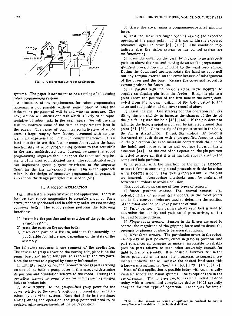
Fig. 1. A representative robot application.
systems. The paper is not meant to be a catalog of all existing robot programming systems.
A discussion of the requirements for robot programming languages is not possible without some notion of what the tasks to be programmed will be and who the users are. The next section will discuss one task which is likely to be repre- sentative of robot tasks in the near future. We will use this task to motivate some of the detailed requirements later in the paper. The range of computer sophistication of robot users is large, ranging from factory personnel with no pro- gramming experience to Ph.D.'s in computer science. It is a fatal mistake to use this fact to argue for reducing the basic functionality of robot programming systems to that accessible to the least sophisticated user. Instead, we argue that robot programming languages should support the functional require- ments of its most sophisticated users. The sophisticated users can implement special-purpose interfaces, in the language itself, for the less experienced users. This is the approach taken in the design of computer programming languages; it also echoes the design principles discussed in [ 96 1 .
11. A ROBOT APPLICATION
Fig. 1 illustrates a representative robot application. The task involves two robots cooperating to assemble a pump. Parts arrive, randomly oriented and in arbitrary order, on two moving conveyor belts. The robot system performs the following functions:
1) determine the position and orientation of the parts, using
2) grasp the parts on the moving belts; 3) place each part on a fixture, add it to the assembly, or
put it aside for future use, depending on the state of the assembly .
a vision system;
The following sequence is one segment of the application. The task is to grasp a cover on the moving belt, place it on the pump base, and insert four pins so as to align the two parts. Note the central role played by sensory information.
1) Identify, using vision, the (nonoverlapping) parts arriving on one of the belts, a pump cover in this case, and determine its position and orientation relative to the robot. During this operation, inspect the pump cover for defects such as missing holes or broken tabs.
2) Move ROBOT1 to the prespecified grasp point for the cover, relative to the cover's position and orientation as deter- mined by the vision system. Note that if the belt continues moving during the operation, the grasp point will need to be updated using measurements of the belt's position.
3 ) Grasp the cover using a programmer-specified gripping force.
4) Test the measured finger opening against the expected opening at the grasp point. If it is not within the expected tolerance, signal an error [61, [ 1031. This condition may indicate that the vision system or the control system are malfunctioning.
5) Place the cover on the base, by moving to an approach position above the base and moving down until a programmer- specified upward force is detected by the wrist force sensor. During the downward motion, rotate the hand so as to null out any torques exerted on the cover because of misalignment of the cover and the base. Release the cover and record its current position for future use.
6 ) In parallel with the previous steps, move ROBOT2 to acquire an aligning pin from the feeder. Bring the pin t o a point above the position of the first hole in the cover, com- puted from the known position of the hole relative to the cover and the position of the cover recorded above.
7 ) Insert the pin. One strategy for this operation requires tilting the pin slightly to increase the chances of the tip of the pin falling into the hole [43], [44]. If the pin does not fall into the hole, a spiral search can be initiated around that point [ 61, [ 3 1 1 . Once the tip of the pin is seated in the hole, the pin is straightened. During this motion, the robot is instructed to push down with a prespecified force, to push in the y direction (so as to maintain contact with the side of the hole), and move so as to null out any forces in the x direction [44] . At the end of this operation, the pin position is tested t o ascertain that it is within tolerance relative to the computed hole position.
8) In parallel with the insertion of the pin by ROBOT2, ROBOT^ fetches another pin and proceeds with the insertion when ROBOT2 is done. This cycle is repeated until all the pins are inserted. Appropriate interlocks must be maintained between the robots to avoid a collision.
This application makes use of four types of sensors: 1) Direct position sensors. The internal sensors, e.g.,
potentiometers or incremental encoders, in the robot joints and in the conveyor belts are used to determine the position of the robot and the belt at any instant of time.
2) Vision sensors. The camera above each belt is used to determine the identity and position of parts arriving on the belt and to inspect them.
3) Finger touch sensors. Sensors in the fingers are used to control the magnitude of the gripping force and t o detect the presence or absence of objects between the fingers.
4 ) Wrist force sensors. The positioning errors in the robot, uncertainty in part positions, errors in grasping position, and part tolerances all conspire to make it impossible to reliably position parts relative to each other accurately enough for tight tolerance assembly. It is possible, however, t o use the forces generated as the assembly progresses to suggest incre- mental motions that will achieve the desired final state; this isknownascompZiuntmotion,'e.g., [601,[791,[1011,[1021.
Most of this application is possible today with commerically available robots and vision systems. The exceptions are in the use of sensing. The pin insertion, for example, would be done today with a mechanical compliance device [ 1021 specially designed for this type of operation. Techniques for imple-
compliance achievable with mechanical devices. This is also known as active compliance in contrast to passive
LOZANO-PEREZ: ROBOT PROGRAMMING 823
menting compliant motion via force feedback are known, e.g., [ 7 3 ] , [ 751 , [ 7 9 ] , [88] ; but current force feedback methods are not as fast or as robust as mechanical compliance devices. Current commercial vision systems would also impose limita- tions on the task, e.g., parts must not be touching. Improved techniques for vision and compliance are key areas of robotics research.
111. REQUIREMENTS OF ROBOT PROGRAMMING
The task described above illustrates the major aspects of sophisticated robot programming: sensing, world modeling, motion specification, and flow of control. This section dis- cusses each of these issues and their impact on robot programming.
A . Sensing
The vast majority of current industrial robot applications are performed using position control alone without significant external sensing. Instead, the environment is engineered so as to eliminate all significant sources of uncertainty. All parts are delivered by feeders, for example, so that their positions will be known accurately at programming time. Special-purpose devices are designed to compensate for uncertainty in each grasping or assembly operation. This approach requires large investments in design time and special-purpose equipment for each new application. Because of the magnitude of the investment, the range of profitable applications is limited; because of the special-purpose nature of the equipment, the capability of the system to respond to changes in the design of the product or in the manufacturing method is negligible. Under these conditions, much of the potential versatility of robots is wasted.
Sensing enables robots to perform tasks in the presence of significant environmental uncertainties without special-pur- pose tooling. Sensors can be used to identify the position of parts, to inspect parts, to detect errors during manufacturing operations, and to accomodate to unknown surfaces. Sensing places two key requirements on robot programming systems. The first requirement is to provide general input and output mechanisms for acquiring sensory data. This requirement can be met simply by providing the 1 /0 mechanisms available in most high-level computer programming languages, although this has seldom been done. The second requirement is t o pro- vide versatile control mechanisms, such as force control, for using sensory data to determine robot motions. This need to specify parameters for sensor-based motions and to specify alternate actions based on sensory conditions is the primary motivationfor using sophisticated robotprogramminglanguages.
Sensors are used for different purposes in robot programs; each purpose has a separate impact on the system design. The principal uses of sensing in robot Programming are as follows
1) initiating and terminating motions, 2 ) choosing among alternative actions, 3 ) obtaining the identity and position of objects and features
4) complying to external constraints.
The most common use of sensory data in existing systems is to initiate and terminate motions. Most robot programming systems provide mechanisms for waiting for an external binary signal before proceeding with execution of a program. This capability is used primarily to synchronize robots with other machines. One common application of this capability arises
of objects,
when acquiring parts from feeders; the robot’s grasping motion is initiated when a light beam is interrupted by the arrival of a new part at the feeder. Another application is that of locating an imprecisely known surface by moving towards it and ter- minating the approach motion when a microswitch is tripped or when the value of a force sensor exceeds a threshold. This type of motion is known as a guarded move [ 1041 or stop on force [ 6 ] , [ 731. Guarded moves can be used to identify points on the edges of an imprecisely located object such as a pallet. The contact points can then be used to determine the pallet’s position relative to the robot and supply offsets for subsequent pickup motions. Section IV-A illustrates a limited form of this technique available within some existing guiding systems. General use of this technique requires computing new positions on the basis of stored values; hence it is limited to robot-level languages.
The second major use of sensing is in choosing among alter- native actions in a program. One example is deciding whether to place an object in a fixture or a disposal bin depending on the result of an inspection test. Another, far more common, example arises when testing whether a grasp or insert action had the desired effect and deciding whether to take corrective action. This type of error checking accounts for the majority of the statements in many robot programs. Error checking requires the ability to obtain data from multiple sensors, such as visual, force, and position sensors, to perform computations on the data, and to make decisions on the results.
The third major use of sensing in robot systems is in obtaining the identity and position of objects or features of objects. For example in the application described earlier, a vision module is used to identify and locate objects amving on con- veyor belts. Because vision systems are sizable programs requiring large amounts of processing, they often are imple- mented in separate processors. The robot program must be able, in these cases, to interface with the external system at the level of symbolic data rather than at the level of “raw” sensory data. Similar requirements arise in interfacing to manufacturing data bases which may indicate the identity of the objects in different positions of a pallet, for example. From these considerations we can conclude that robot pro- gramming systems should provide general input/output inter- faces, including communications channels to other computers, not just a few binary or analog channels as is the rule in today’s robot systems.
Once the data from a sensor or database module are obtained, some computation must be performed on the module’s output so as to obtain a target robot position. For example, existing commercial vision systems can be used to compute the position of the center of area of an object’s outline and the orientation of the line that minimizes the second moment. These measure- ments are obtained relative to the camera’s coordinate system. Before the object can be grasped, these data must be related to the robot’s coordinate system and combined with informa- tion about the relationship of the desired grasp point to the measured data (see Section 111-B). Again, this points out the interplay between the requirements for obtaining sensory data and for processing them.
The fourth mode of sensory interaction, active compliance, is necessary in situations requiring continuous motion in response to continuous sensory input. Data from force, proximity, or visual sensors can be used to modify the robot’s motion so as to maintain or achieve a desired relationship with other objects. The forcecontrolled motions to turn a crank, for example, require that the target position of the

824 PROCEEDINGS OF THE IEEE, VOL. 71, NO. 7, JULY 1983
robot from instant to instant be determined from the direction and magnitude of the forces acting on the robot hand, e.g., [601, [ 761. Other examples are welding on an incompletely known or moving surface, and inserting a peg in a hole when the position uncertainty is greater than the clearance between the parts. Compliant motion is an operation specific to ro- botics; it requires special mechanisms in a robot programming system.
There are several techniques for specifying compliant motions, for a review see [ 621. One method models the robot as a spring whose stiffness along each of the six motion freedoms can be set [ 351, [83]. This method ensures that a linear relationship is maintained between the force which is sensed and the dis- placements from a nominal position along each of the motion freedoms. A motion specification of this type requires the following information:
1) A coordinate frame in which the force sensor reading are to be resolved, known as the constraint frame. Some common alternatives are: a frame attached to the robot hand, a fixed frame in the room, or a frame attached to the object being manipulated.
2) The desired position trajectory of the robot. This specifies the robot’s nominal position as a function of time.
3) Stiffnesses for each of the motion freedoms relative to the constraint frame. For example, a high stiffness for trans- lation along the x-axis means that the robot will allow only small deviations from the position specified in the trajectory, even if high forces are felt in the x direction. A low stiffness, on the other hand, means that a small force can cause a sig- nificant deviation from the position specified by the trajectory.
The specification of a compliant motion for inserting a peg in a hole [62] is as follows: The constraint frame will be located at the center of the peg’s bottom surface, with its z- axis aligned with the axis of the peg. The insertion motion will be a linear displacement in the negative z direction, along the hole axis, to a position slightly below the expected final destination of the peg.
The stiffnesses are specified by a matrix relating the Cartesian position parameters of the robot’s end effector to the force sensor inputs
f = K A
where f is a 6 X 1 vector of forces and torques, K is a 6 X 6 matrix of stiffnesses, and A is a 6 X 1 vector of deviations of the robot from its planned path. While inserting a peg in a hole, we wish the constraint frame to follow a trajectory straight down the middle of the hole, but complying with forces along the x- and y-axes and with torques about the x- and y-axes. The stiffness matrix K for this task would be a diagonal matrix
K = d i a g ( k o , k o , k l , k o , k o , k l )
where ko indicates low stiffness and k l a high stiffness.’ The complexity of specifying the details of a compliant
motion argues for introducing special-purpose syntactic mechanisms into robot languages. Several such mechanisms have been proposed for different compliant motion types [671, 1751, [761, [831.
One key difference between the first three sensor inter-
’ Unfortunately, the numerical choices for stiffnesses are dictated by detailed considerations of characteristics of the environment and of the control system [ 101 1 , 13 5 1 .
action mechanisms and active compliance is extensibility. The first three methods allow new sensors and modules t o be added or changed by the user, since the semantics of the sensor is determined only by the user program. Active com- pliance, on the other hand, requires much more integration between the sensor and the motion control subsystem; a new type of sensor may require a significant system extension. Ideally, a user’s view of compliant motion could be imple- mented in terms of lower level procedures in the same robot language. Sophisticated users could then modify this imple- mentation to suit new applications, new sensors, or new motion algorithms. In practice efficiency considerations have ruled out this possibility since compliant motion algorithms must be executed hundreds of times a ~ e c o n d . ~ This is not a fundamental restriction, however, and increasing computer power, together with sophisticated compilation techniques, may allow future systems to provide this desirable capability.
In summary, we have stressed the need for versatile input/ output and computation mechanisms to support sensing in robot programming systems. The most natural approach for providing these capabilities is by adopting a modern hgh-level computer language as the basis for a robot programming lan- guage. We have identified one sensor-based mechanism; namely, compliant motion, that requires specific language mechanisms beyond those of traditional computer languages.
In addition to the direct mechanisms needed to support sensing within robot programming languages, there are mech- anisms needed due to indirect effects of the reliance on sensing for robot programming. Some of these effects are as follows:
1) Target positions are not known at programming time; they may be obtained from an external database or vision sensor or simply be defined by hitting something.
2) The actual path to be followed is not known at pro- gramming time; it may be determined by the history of sen- sory inputs.
3) The sequence of motions is not known at programming time; the result of sensing operations will determine the actual execution sequence.
These effects of sensing have significant impact on the structure of robot programming systems. The remainder of this section explores these additional requirements.
B. World Modeling
Tasks that do not involve sensing can be specified as a sequence of desired robot configurations; there is no need to represent the geometrical structure of the environment in terms of objects. When the environment is not known a priori, however, some mechanism must be provided for representing the positions of objects and their features, such as surfaces and holes. Some of these positions are fixed throughout the task, others must be determined from sensory information, and others bear a fixed relationship with respect to variable positions. Grasping an object, for example, requires specifying the desired position of the robot’s gripper relative to the object’s position. At execution time, the actual object position is determined using a vision system or on-line database. The desired position for the gripper can be determined by com- posing the relative grasp position and the absolute object position; this gripper position must then be transformed to a
3Reference [ 2 7 ] describes a robot system architecutre that enables different sensors to be interfaced into the motion control subsystem from the user language level; see also 1751 for a different proposal.

LOZANO-PEREZ: ROBOT PROGRAMMING 825
WORLD
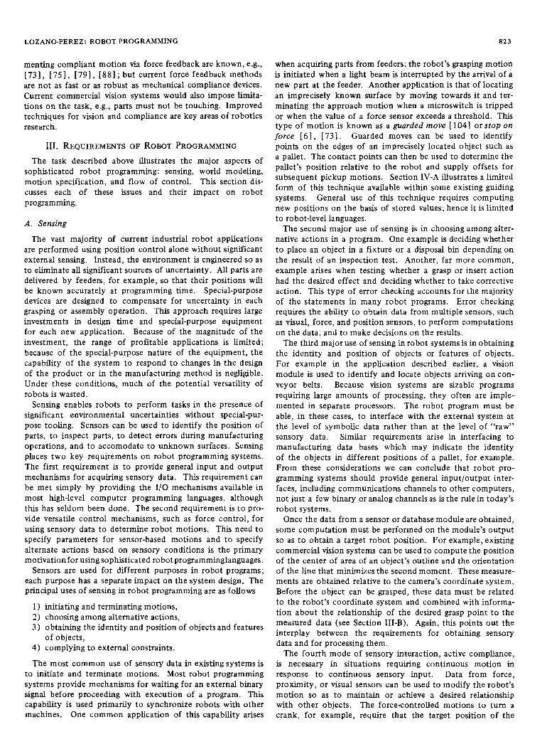
Fig. 2. World model with coordinate frames.
robot configuration. A robot programming system should facilitate this type of computation on object positions and robot configurations.
The most common representation for object positions in robotics and graphics is the homogeneous transform, repre- sented by a 4 X 4 matrix [ 751. A homogeneous transform matrix expresses the relation of one coordinate frame to another by combining a rotation of the axes and a translation of the origin. Two transforms can be composed by multiplying the corresponding matrices. The inverse of a transform which relates frame A to frame B is a transform which relates B to A . Coordinate frames can be associated with objects and features of interest in a task, including the robot gripper or tool. Transforms can then be used to express their positions with respect to one another.
A simple world model, with indicated coordinate frames, is sh’own in Fig. 2 . The task is to visually locate the bracket on the table, grasp it, and insert the pin, held in a stationary fixture, into the bracket’s hole. A similar task has been analyzed in [ 331 , [ 931.
The meaning of the various transforms indicated in Fig. 2 are as follows. Cam is the transform relating the camera frame to the WORLD frame. Grasp is the transform relating the desired position of the gripper’s frame to the bracket’s frame. Let Bracket be the unknown transform that relates the bracket frame to WORLD. We will be able to obtain from the vision system the value of B k t , a transform relating the bracket’s frame to the camera’s frame.4 HoZe is a transform relating the hole’s frame to that of the bracket. The value of Hole is known from the design of the bracket. Pin relates the frame of the pin to that of the fixture. Fixture, in turn, relates the fixture’s frame to WORLD. Z relates the frame of the robot base to WORLD. Our goal is to determine the transform relating the endeffector’s (gripper’s) frame E relative to the robot’s base. Given E and Z, the robot’s joint angles can be determined (see, for example, [ 75 I ).
The first step of the task is determining the value of Bracket, which is simply Cam Bkt . The desired gripper position for grasping the bracket is
Z E = Bracket Grasp.
Since Cam is relative t o WORLD, Bkt relative to Cam, and Grasp relative to B k t , the composition gives us the desired gripper position relative to WORLD, i.e., 2 E . At the target
position we want the location of the hole relative to WORLD to be equal to that of the pin; this relationship can be expressed as
Bracket Hole =Fixture Pin.
From this we can see that
Bracket = Fixture Pin Hole-‘.
Hence, the new gripper location is
Z E = Fixture Pin Hole-’ Grasp.
The use of coordinate frames to represent positions has two drawbacks. One drawback is that a coordinate frame, in gen- eral, does not specify a robot configuration uniquely. There may be several robot configurations that place the endeffector in a specified frame. For a robot with six independent motion freedoms, there are usually on the order of eight robot con- figurations to place the gripper at a specified frame. Some frames within the robot’s workspace may be reached by an infinite number of configurations, however. Furthermore, for robots with more than six motion freedoms, the typical coordinate frames in the workspace will be achievable by an infinite number of configurations. The different configurations that achieve a frame specification may not be equivalent; some configurations, for example, may give rise to a collision while others may not. This indeterminacy needs to be settled at programming time, which may be difficult for frames deter- mined from sensory data.
Another, dual, drawback of coordinate frames is that they may overspecify a configuration. When grasping a symmetric object such as a cylindrical pin, for example, it may not be necessary to specify the orientation of the gripper around the symmetry axis. A coordinate frame will always specify this orientation, however. Thus if the vision system describes the pin’s position as a coordinate frame and the grasping position is specified likewise, the computed grasp position will specify the gripper’s orientation relative to the pin’s axis. In some cases this wiU result in a wasted alignment motion; in the worst case, the specified frame may not be reachable because of physical limits on joint travel of the robot. Another use of partially specified object positions occurs in the interpretation of sensory data. When the robot makes contact with an object, it acquires a constraint on the position of that object. This information does not uniquely specify the object’s position, but several such measurements can be used to update the robot’s estimate of the object’s positions [ 6 ] . This type of computation requires representing partially constrained positions or, equivalently, constraints on the position param- eters [ 9 4 1 , [ 141.
Despite these drawbacks, coordinate frames are likely to continue being the primary representation of positions in robot programs. Therefore, a robot programming system should support the representation of coordinate frames and computations on frames via transforms. But this is not all; a world model also should provide mechanisms for describing the constraints that exist between the positions. The simplest case of this requirement arises in managing the various features on a rigid object. If the object is moved, then the positions of all its features are changed in a predictable way. The respons- ibility for updating all of these data should not be left with the programmer; the programming system should provide mechanisms for indicating the relationships between positions

826 PROCEEDINGS OF THE IEEE, VOL. 71, NO. 7, JULY 1983
BLOCK 2
BLOCK I
Fig. 3. Symbolic specification of positions.
so that updates can be carried automatically. Several existing languages provide mechanisms for this, e.g., AL [671 and LM [48].
Beyond representation and computation on frames, robot systems must provide powerful mechanisms for acquiring frames. A significant component of the specification of a robot task is the specification of the positions of objects and features. Many of the required frames, such as the position of the hole relative to the bracket frame in the example above, can be obtained from drawings of the part. This process is extremely tedious and error prone, however. Several methods for obtaining these data have been proposed:
1) using the robot to define coordinate frames; 2) using geometric models from Computer-Aided Design
(CAD) databases; 3 ) using vision systems.
The first of these methods is the most common. A robot’s endeffector defines a known coordinate frame, therefore guiding the robot to a desired position provides the transform needed to define the position. Relative positions can be determined from two absolute positions. Two drawbacks of this simple approach are: some of the desired coordinate frames are inaccessible to the gripper, also, the orientation accuracy achievable by guiding and visual alignment is limited.’ These problems can be alleviated by computing transforms from some number of points with known relationships t o each other, e.g., the origin of the frame and points on two of the axes. Indicating points is easier and more reliable than aligning coordinate systems. Several systems implement this approach, e.g., AL [331, [671 and VAL [881, [981.
A second method of acquiring positions, which is likely t o grow in importance, is the use of databases from CAD systems. CAD systems offer significant advantages for analysis, docu- mentation, and management of engineering changes. Therefore, they are becoming increasingly common throughout industry. CAD databases are a natural source for the geometric data needed in robot programs. The descriptions of objects in a CAD database may not be in the form convenient for the robot programmer, however. The desired object features may not be explicitly represented, e.g., a point in the middle of a parametrically defined surface. Furthermore, positions specific to the robot task, such as grasp points, are not represented a t all, and must still be specified. Therefore, the effective use of CAD databases requires a high-level interface for specifying the desired positions. Pointing on a graphics screen is one pos- sibility, but is suffers from the two-dimensional restrictions of
graphics [ 21. Another method [ 1 1, [801 is t o describe posi- tions by sets of symbolic spatial relationships that hold between objects in each position. For example, the positions of Block 1 in Fig. 3 must satisfy the following relationships:
(f3 Against f l ) and (f4 Against f2).
One advantage of using symbolic spatial relationships is that the positions they denote are not limited to the accuracy of a light-pen or of a robot, but that of the model. Another advantage of this method is that families of positions such as those on a surface or along an edge can be expressed. Further- more, people easily understand these relationships. One small drawback of symbolic relations is that the specifications are less concise than specifications of coordinate frames.
Another potentially important method of acquiring posi- tions is the use of vision. For example, two cameras can simultaneously track a point of light from a laser pointer and the system can compute the position of the point by triangu- lation [ 371. One disadvantage of this method and of methods based on CAD models is that there is no guarantee that the specified point can be reached without collisions.
We have focused on the representation of single positions; this reflects the emphasis in current robot systems on end- point specification of motions. In many applications, this emphasis is misplaced. For example, in arc-welding, grinding, glue application, and many other applications, the robot is called upon to follow a complex path. Currently these paths are specified as a sequence of positions. The next section discusses alternative methods of describing motions which require representing surfaces and volumes. A large repertoire of representational and computational tools is already avail- able in CAD systems and Numerically Controlled (NC) ma- chining systems, e.g., [21 l .
In summary, the data manipulated by robot programs are primarily geometric. Therefore, robot programming systems have a requirement t o provide suitable data input, data repre- sentation, and computational capabilities for geometric data. Of these three, data input is the most amenable to solutions that exploit the capabilities of robot systems, e.g., the avail- ability of the robot and its sensors.
C. Motion Specification The most obvious aspect of robot programming is motion
specification. The solution appears similarly obvious: guiding. But, guiding is sufficient only when all the desired positions and motions are known at programming time. We have post- poned a discussion of motion specification until after a dis- cussion of sensing and modeling to emphasize the broader. range of conditions under which robot motion must be speci- fied in sensor-based applications.
Heretofore, we have assumed that a robot motion is specified by its final position, be it in absolute coordinates or relative to some object. In many cases, this is not sufficient; a path for the robot must also be specified. A simple example of this requirement arises when grasping parts: the robot cannot approach the grasp point from arbitrary directions; it must typically approach from above or risk colliding with the part.
5A common assumption is that since the accuracy of the robot limits Similarly, when bringing the part to add to a subassembly,
execution. the same accuracy is sufficient during task sDecification. This the approach path must be specified‘ Paths are assumption neglects the effect of the robot’s Limited repeatability, how- commonly specified by indicating a sequence of intermediate ever. Errom in achieving the specified position, h e n compounded with positions, known as via points, that the robot should traverse the specification errors, might cause the operation t o fail. Further- more, if the location is used as the basis for relative locations, the between the and positions. propagation of errors can make reliable execution impossible. The shape of the path between via points is chosen from

LOZANO-PEREZ: ROBOT PROGRAMMING 821
among some basic repertoire of path shapes implemented by the robot control system. Three types of paths are imple- mented in current systems: uncoordinated joint motions, straight lines in the joint coordinate space, and straight lines in Cartesian space. Each of these represents a different tradeoff between speed of execution and “natural” behavior. They are each suitable to some applications more than others. Robot systems should support a wide range of such motion regimes.
One important issue in motion specification arises due to the nonuniqueness of the mapping from Cartesian to joint coordinates. The system must provide some well-defined mechanism for choosing among the alternative solutions. In some cases, the user needs to identify which solution is appropriate. VAL provides a set of configuration commands that allow the user to choose one of the up to eight joint solutions available at some Cartesian positions. This mech- anism is useful, but limited. In particular, it cannot be ex- tended to redundant robots with infinite families of solutions or to specify the behavior at a kinematic singularity.
Some applications, such as arc-welding or spray-painting, can require very fine control of the robot’s speed along a path, as well as of the shape of the path [ 9 1 , [ 7 5 ] . This type of specification is supported by providing explicit trajectory control commands in the programming system. One simple set of commands could specify speed and acceleration bounds on the trajectory. AL provides for additional specifications such as the total time of the trajectory. Given a wide range of constraints, it is very likely that the set of constraints for particular trajectories will be inconsistent. The programming system should either provide a well-defined semantics for treating inconsistent constraints6 or make it impossible to specify inconsistent constraints. Trajectory constraints also should be applicable to trajectories whose path is not known at programming time, for example, compliant motions.
The choice of via points for a task depends on the geometry of the parts, the geometry of the robot, the shape of the paths the robot follows between positions, and the placement of the motion in the robot workspace. When the environment is not known completely at programming time, the via points must be specified very conservatively. This can result in un- necessarily long motions.
An additional drawback of motions specified by sequences of robot configurations is that the via points are chosen, typically, without regards for the dynamics of the robot as it moves along the path. If the robot is to go through the via points very accurately, the resulting motion may have t o be very slow. This is unfortunate, since it is unlikely that the programmer meant the via points exactZy. Some robot sys- tems assume that via points are not meant exactly unless told otherwise. The system then splines the motion between path segments t o achieve a fast, smooth motion, but one that does not pass through the via points [751 . The trouble is that the path is then essentially unconstrained near the via points; furthermore, the actual path followed depends on the speed of the motion.
A possible remedy for both of these problems is to specify the motion by a set of constraints between features of the robot and features of objects in the environment. The exe- cution system can then choose the “best” motion that satisfies
these constraints, or signal an error if no motion is possible. This general capability is beyond the state of the art in tra- jectory planning, but a simple form has been implemented. The user specifies a nominal Cartesian path for the robot plus some allowed deviation from the path; the trajectory planner then plans a joint space trajectory that satisfies the constraints [951 .
Another drawback of traditional motion specification is the awkwardness of specifying complex paths accurately as se- quences of positions. More compact descriptions of the desired path usually exist. An approach followed in NC machining is to describe the curve as the intersection of two mathematical surfaces. A recent robot language, MCL 1581, has been defined as an extension t o APT, the standard NC language. The goal of MCL is to capitalize on the geometric databases and compu- tational tools developed within existing APT systems for specifying robot motions. This approach is particularly attractive for domains, such as aircraft manufacture, in which many of the parts are numerically machined.
Another very general approach to trajectory specification is via user-supplied procedures parameterized by time. Paul [ 741, [ 7 5 ] refers to this as functionally defined motion. The pro- gramming system executes the function to obtain position goals. This method can be used, for example, to follow a surface obtained from CAD data, turn a crank, and throw objects. The limiting factor in this approach is the speed at which the function can be evaluated; in existing robot systems, no method exists for executing user procedures at servo rates.
A special case of functionally defined motion is motion specified as a function of sensor values. One example is in compliant motion specifications, where some degrees of freedom are controlled to satisfy force conditions. Another example is a motion defined relative to a moving conveyor belt. Both of these cases are common enough that special- purpose mechanisms have been provided in programming systems. There are significant advantages t o having these mechanisms implemented using a common basic mechanism.
In summary, the view of motion specification as simply specifying a sequence of positions or robot configurations is too limiting. Mechanisms for geometric specification of curves and functionally defined motion should also be pro- vided. No existing systems provide these mechanisms with any generality.
D. Flow of Control In the absence of any form of sensing, a fixed sequence of
operations is the only possible type of robot program. This model is not powerful enough to encompass sensing, however. In general, the program for a sensor-based robot must choose among alternative actions on the basis of its internal model of the task and the data from its sensors. The task of Section 11, for example, may go through a very complex sequence of states, because the parts are amving in random order and because the execution of the various phases of the operation is over- lapped. In each state, the task program must specify the appropriate action for each robot. The programming system must provide capabilities for making these control decisions.
The major sources of information on which control decisions can be based are: sensors, control signals, and the world model. The simplest use of this information is t o include a test at fixed Places in the Program to decide which action should be taken
6 A special case occurs when the computed path goes through a next, e&, “If (i < j ) t hen Signal X else Moveto Y.” One kinematic It s h p w i b l e in to satisfy trajectory important application where this type of control is suitable constraints such as speed of the end-effector at the singularity. is error detection and correction.

828
Robot operations are subject to large uncertainties in the initial state of the world and in the effect of the actions. As a result, the bulk of robot programming is devoted to error detection and correction. Much of this testing consists of comparing the actual result of an operation with the expected results. One common example is testing the finger opening after a grasp operation to see if it differs from the expected value, indicating either that the part is missing or a different part is there. This type of test can be easily handled with traditional IF-THEN tests after completion of the operation. This test is so common that robot languages such as VAL and WAVE [74] have made it part of the semantics of the grasp command.
Many robot applications also have other requirements that do not fall naturally within the scope of the IF-THEN control structure. Robot programs often must interact with people or machines, such as feeders, belts, NC machines, and other robots. These external processes are executing in parallel and asynchronously; therefore, it is not possible to predict exactly when events of interest to the robot program may occur. In the task of Section 11, for example, the arrival of a part within the field of view of one of the cameras calls for imme- diate action: either one of the robots must be interrupted so as to acquire the part, or the belt must be stopped until a robot can be interrupted. The previous operations may then be resumed. Other examples occur in detecting collisions or part slippage from the fingers; monitor processes can be created to continuously monitor sensors, but they must be able to interrupt the controlling process and issue robot commands without endangering ongoing tasks.
It is possible to use the signal lines supported by most robot systems to coordinate multiple robots and machines. For example, in the sample task, the insertion of the pins into the pump cover (steps 6 through 8, Section 11) requires that ROBOTl and ROBOT2 be coordinated so as to minimize the duration of the operation while avoiding interference among the robots. If we let ROBOTl be in charge, we can coordinate the operation using the following signal lines:
1) GET-PIN?: ROBOT2 asks if it is safe to get a new pin. 2) OK-TO-GET: ROBOT 1 says it is OK. 3) INSERT?: ROBOT2 asks if it is safe to proceed to insert
4) OK-TO-INSERT: ROBOT1 says it is OK. 5) DONE : ROBOT 1 says it is al l over.
the pin.
The basic operation of the control programs could be as follows:
ROBOTl ROBOT2 Wait for COVER-ARRIVED 3: Signal OK-TOGET
Call PlaceCover-in-Fixture i : = 1
Wait for INSERT-PIN? Signal OK-TO-INSERT if (i < np) then do
[Call Get-Pin-1 i : = i + 11 4:
else do [Signal DONE Goto 21
if (i < np) then do Wait for GET-PIN?
[Signal OK-TOGET i : = i + 11
Call Insert-Pin-1 Goto 1 . . .
If signal DONE Goto 4 Signal GET-PIN?
Call Get-Pin-2 Signal INSERT-PIN? Wait for OK-TO-INSERT Call Insert-Pin-2 Goto 3
Wait for OK-TO-GET
. . .
This illustration of how a simple coordination task could be
PROCEEDINGS OF THE IEEE, VOL. 71, NO. 7 , JULY 1983
done with only binary signals also serves to illustrate the limitations of the method.
1) The programs are asymmetric; one robot is the master of the operation. If the cover can arrive on either belt and be retrieved by either robot, then either an additional signal line is needed to indicate which robot will be the master or both robot systems must be subordinated to a third controller.
2) If one of the robots finds a defective pin, there is no way for it to cause the other robot to insert an additional pin while it goes to dispose of the defective one. The program must allocate new signal lines for this purpose. In general, a large number of signals may be needed.
3) Because one robot does not know the position of the other one, it is necessary to coordinate them on the basis of very conservative criteria, e.g., being engaged in getting a pin or inserting a pin. This will result in slow execution unless the tasks are subdivided very finely and tests performed at each division, which is cumbersome.
4) The position of the pump cover and the pin-feeder must be known by each process independently. No information obtained during the execution of the task by one robot can be used by the other robot; it must discover the information independently.
The difficulties outlined above are the due to limited com- munication between the processes. Signal lines are a simple, but limited, method of transferring information among the processes. In practice, sophisticated tasks require efficient means for coordination and for sharing the world model (including the state of the robots) between processes.
The issue of coordination between cooperating and com- peting asynchronous processes is one of the most active research areas in Computer Science. Many language mech- anisms have been proposed for process synchronization, among these are: semaphores [ 171, events, conditional critical regions [ 391, monitors and queues [ 11 1 , and communicating sequential processes [40]. Robot systems should build upon these developments, perhaps by using a language such as Concurrent Pascal [ 11 ] or Ada [42] as a base language. A few existing robot languages have adopted some of these mechanisms, e.g., AL and TEACH [81] , [821. Even the most sophisticated developments in computer languages do not address all the robot coordination problems, however.
When the interaction among robots is subject to critical real-time constraints, the paradigm of nearly independent control with periodic synchronization is inadequate. An example occurs when multiple robots must cooperate phys- ically, e.g., in lifting an object too heavy for any one. Slight deviations from a pre-planned position trajectory would cause one of the robots to bear all the weight, leading to disaster. What is needed, instead, is cooperative control of both robots based on the force being exerted on both robots by the load [ 45 I , [ 601, [ 681. The programming system should provide a mechanism for specifying the behavior of systems more com- plex than a single robot. Another example of the need of this kind of coordination is in the programming and control of multifingered grippers [ 841.
In summary, existing robot programming systems are based on the view of a robot system as a single robot weakly linked to other machines. In practice, many machines including sensors, special grippers, feeders, conveyors, factory control computers, and several robots may be cooperating during a task. Furthermore, the interactions between them may be highly dynamic, e.g., to maintain a force between them, or may require extensive sharing of information. No existing

LOZANO-PBREZ: ROBOT PROGRAMMING 8 2 9
robot programming system adequately deals with all of these interactions. In fact, no existing computer language is adequate to deal with this kind of parallelism and real-time constraints.
E. Programming Support Robot applications do not occur in a vacuum. Robot pro-
grams often must access external manufacturing data, ask users for data or corrective action, and produce statistical reports. These functions are typical of most computer applications and are supported by all computer programming systems. Many robot systems neglect to support them, however. In principle, the exercise of these functions can be separated from the specification of the task itself but, in practice, they are inti- mately intertwined. A sophisticated robot programming sys- tem must first be a sophisticated programming system. Again, this requirement can be readily achieved by embedding the robot programming system within an existing programming system [ 751. Alternatively, care must be taken in the design of new robot programming systems not to overlook the “mundane” programming functions.
A similar situation exists with respect t o program develop- ment. Robot program development is often ignored in the design of robot systems and, consequently, complex robot programs can be very difficult to debug. The development of robot programs has several characteristics which merit special treatment.
1) Robot programs have complex side-effects and their execution time is usually long, hence it is not always feasible to re-initialize the program upon failure. Robot programming systems should allow programs to be modified on-line and immediately restarted.
2) Sensory information and real-time interactions are not usually repeatable. One useful debugging tool for sensor- based programs provides the ability to record the sensor outputs, together with program traces.
3 ) Complex geometry and motions are difficult t o visualize; simulators can play an important role in debugging, for example, see [ 3 8 1 , [ 6 5 ] , [ 9 1 1 .
These are not minor considerations, they are central to increased usefulness of robot programming systems.
Most existing robot systems are stand-alone, meant to be used directly by a single user without the mediation of com- puters. This design made perfect sense when robots were not controlled by general-purpose computers; today it makes little sense. A robot system should support a high-speed command interface to other computers. Therefore, if a user wants t o develop an alternate interface, he need not be limited by the performance of the robot system’s user interface. On the other hand, the user can take advantage of the control system and kinematics calculations in the existing system. This design would also facilitate the coordination of multiple robots and make sophisticated applications easier to develop.
Iv. SURVEY OF ROBOT PROGRAMMING SYSTEMS
In this section, we survey several existing and proposed robot Programming systems. An additional survey of robot pro- gramming systems can be found in [ 71.
A. Guiding All robot programming systems support some form of
guiding. The simplest form of guiding is to record a sequence of robot positions that can then be “played back”; we call
this basic guiding. In robot-level systems, guiding is used t o define positions while the sequencing is specified in a program.
The differences among basic guiding systems are a) in the way the positions are specified and b) the repertoire of motions between positions. The most common ways of specifying positions are: by specifying incremental motions on a teach- pendant, and by moving the robot through the motions, either directly or via a master-slave linkage.
The incremental motions specified via the teach-pendant can be interpreted as: independent motion of each joint between positions, straight lines in the joint-coordinate space, or straight lines in Cartesian space relative to some coordinate system, e.g., the robot’s base or the robot’s end-effector. When using the teach-pendant, only a few positions are u s u d y recorded, on command from the instructor. The path of the robot is then interpolated between these positions using one of the three types of motion listed above.
When moving the robot through the motions directly, the complete trajectory can be recorded as a series of closely spaced positions on a fixed time base. The latter method is used primarily in spray-painting, where it is important to duplicate the input trajectory precisely.
The primary advantage of guiding is its immediacy: what you see is what you get. In many cases, however, it is ex- tremely cumbersome, as when the same position (or a simple variation) must be repeated at different points in a task or when fine positioning is needed. Furthermore, we have indicated repeatedly the importance of sensing in robotics and the limitations of guiding in the context of sensing. Another important limitation pf basic guiding is in expressing control structures, which inherently require testing and describing alternate sequences.
1 ) Extended Guiding: The limitations of basic guiding with respect t o sensing and control can be abated, though not com- pletely abolished, by extensions short of a full programming language. For example, one of the most common uses of sensors in robot programs is to determine the location of some object to be manipulated. After the object is located, subsequent motions are made relative to the object’s coordinate frame. This capability can be accomodated within the guiding paradigm if taught motions can be interpreted as relative t o some coordinate frame that may be modified at execution time. These coordinate frames can be determined, for example, by having the robot move until a touch sensor on the end- effector encounters an object. This is known asguarded motion or a search. This capability is part of some commercial robot systems, e.g., ASEA [ 3 ] , Cincinatti Milacron [ 4 1 ] , and IBM [321, 1921. This approach could be extended to the case when the coordinate frames are obtained from a vision system.
Some guiding systems also provide simple control structures. For example, the instructions in the taught sequence are given numbers. Then, on the basis of tests on external o r internal binary signals, control can be transferred to different points in the taught sequence. The ASEA and Cincinatti Milacron guiding systems, for example, both support conditional branching. These systems also support a simple form of procedures. The procedures can be used to carry out common operations performed at different times in the taught sequence, such as common machining operations applied to palletized parts. The programmer can exploit these facilities to produce more compact programs. These control structure capabilities are limited, however, primarily because guiding systems do not support explicit computation.
To illustrate the capabilities of extended guiding systems,

830 PROCEEDINGS OF THE IEEE, VOL. 71, NO. 7, JULY 1983
L- INPUT PALLET
PICKUP OPERATION ( D E T A I L )
TARGET CONTACT
TARGET GRASP
Fig. 4. Palletizing task.
we present a simple task programmed in the ASEA robot’s guiding system.’ The task is illustrated in Fig. 4 ; it consists of picking a series of parts of different heights from a pallet, moving them to a drilling machine, and placing them on a different pallet. The resulting program has the following structure:
I.No. 10 20 30 40 50 60 100 110 130 140 160 170 200 210 220 23 0 240
Instruction OUTPUT ON 17 PATTERN TEST JUMP 17 JUMP 170 OUTPUT OFF 17
MOD
MOD
MOD
OUTPUT ON 17 MOD
MOD
. . .
. . .
. . . . . .
. . .
Remarks Flag ON indicates do pickup Beginning of procedure Skip next instruction if flag is on
Next time do put down Pickup operation (see below) End of common code for pickup Positioning for fust pickup Execute procedure Positioning for second pickup Execute procedure Machining and put down operation Next time do pickup End of common code for put down Position for first put down Execute procedure Position for second put down
Note that the MOD operation is used with two meanings: 1) to indicate the end of a common section of the PATTERN, and 2) to indicate where the common section is to be executed. The sequence of instructions exected would be: 10, 20, 30, 50, 60 , * * * , 100, . * * , 130, 30, 40, 170;.*, 200;**230, 30, 50, * .
The key to the pickup operation is that we can use a search to locate the top surface of the part, so we need not know the heights exactly. The fingers are initially closed and the robot starts out in position P1, which is above the highest part and vertically above P2, which is at the height of the shortest
ASEA manual [ 31. ’This program is based on two program fragments included in the
part (see Fig. 4). Note that the parts are not in the work- space during the programming sequence.
The pickup sequence could be programmed as follows: 1) Move vertically down towards P2 until contact is felt
2) Open the fiigers (steps 5, 6). We have neglected t o raise
3) Move down the distance between P2 and P3 relative to
4) Close the fingers (steps 10, 1 1 ).
(steps 1-4).
the arm before opening the fingers for simplicity.
the actual location where contact was detected (steps 7-9).
Here is the sequence:
1.
2. 3.
4.
5 .
6.
7. 8. 9.
10.
11.
Programmer action Position vertically to P2.
Select speed to P2. Key code for search and vertical operation
PTPF
Set grip opening and select waiting time.
GRIPPERS
Position to P3.
PTPL Select time for motion.
Set grip opening and select waiting time.
GRIPPERS
Remarks Manual motion to the end position of
search.
This code indicates that the motion that follows is a search in vertical direction.
program. Insert positioning command to P2 in
Specify finger opening
Insert command to actuate grippers (open).
Grasping position (relative to P2).
Coordinated joint motion, relative to the position after the search.
Specify finger closing
Insert command to actuate grippers (close).
The putdown sequence would be programmed in a similar fashion.
2) Off-Line Guiding: Traditional guiding requires that the workspace for the task, all the tooling, and any parts be avail- able during program development. If the task involves a single large or expensive part, such as an airplane, ship or auto- mobile, it may be impractical to wait until a completed part is available before starting the programming; this could delay the complete manufacturing process. Alternatively, the task environment may be in space or underwater. In these cases, a mockup of the task may be built, but a more attractive alternative is available when a CAD model of the task exists. In this case, the task model together with a robot model can be used to define the program by off-line guiding. In this method, the system simulates the motions of the robot in re- sponse to a program or to guiding input from a teach-pendant. Off-line guiding offers the additional advantages of safety and versatility. In particular, it is possible to experiment with different arrangements of the robot relative to the task so as to find one that, for example, minimizes task execution time [381.
B. Robot-Level Programming In Section I11 we discussed a number of important functional
issues in the design of robot programming systems. The design of robot-level languages, by virtue of its heritage in the design of computer languages, has inherited many of the controversies of that notoriously controversial field. A few of these con- troversial issues are important in robot programming:
1) Compiler versus interpreter. Language systems that compile high-level languages into a lower level language can

LOZANO-PEREZ: ROBOT PROGRAMMING
achieve great efficiency of execution as well as early detection of some classes of programming errors. Interpreters, on the other hand, provide enhanced interactive environments, in- cluding debugging, and are more readily extensible. These human factors issues have tended to dominate; most robot language systems are interpreter based. Performance limita- tions of interpreters have sometimes interfered with achieving some useful capabilities, such as functionally defined motions.
2) New versus old. Is it better to design a new language or extend an old one? A new one can be tailored to the need of the new domain. An old one is likely to be more complete, to have an established user group, and to have supporting software packages. In practice, few designers can avoid the temptation of starting de novo; therefore, most robot lan- guages are “new” languages. There are, in addition, difficulties in acquiring sources for existing language systems. One advantage of interpreters in this regard is that they are smaller than compilers and, therefore, easier to build.
In the remainder of the section, we examine some represen- tative robot-level programming systems, in roughly chrono- logical order. The languages have been chosen t o span a wide range of approaches to robot-level programming. We use examples to illustrate the “style” of the languages; a detailed review of all these languages is beyond the scope of this paper. We close the section with a brief mention of some of the many other robot-level programming systems that have been developed in the past ten years.
1 ) MHI 1960-1961: The f i t robot-level programming language, MHI, was developed for one of the earliest computer- controlled robots, the MH-1 at MIT [ 181. As opposed to its contemporary the Unimate, which was not controlled by a general-purpose computer and used no external sensors, MH-I was equipped with several binary touch sensors through- out its hand, an array of pressure sensors between the fingers, and photodiodes on the bottom of the fingers. The availability of sensors fundamentaly affected the mode of programming developed for the MH-1.
MHI (Mechanical Hand Interpreter) ran on an interpreter implemented on the TX-0 computer. The programming style in MHI was framed primarily around guarded moves, i.e., moving until a sensory condition was detected. The language primitives were:
1 j “move”: indicates a direction and a speed; 2 j “until”: test a sensor for some specified condition; 3) “ifgoto”: branch to a program label if some condition is
4) “ifcontinue”: branch to continue action if some condition detected;
holds.
A sample program, taken from [ 181, foliows:
a, move x for 120 ; Move along x with speed 120 until s l 10 re1 lo1 ; until sense organ 1
; indicates a decrease of 10, relative ; to the value at start of this step ; (condition 1)
until s l 206 lo1 abs stp ; or until sense organ 1 indicates ; 206 or less absolute, then stop. ; (condition 2)
ifgoto f l , b : if condition 1 alone is fulfilled
ifgoto t f2 ; go to sequence b ; if at least condition 2 is fulfded ; go to sequence c
ifcontinue t, a ; in all other cases continue sequence a
831
MHI did not support arithmetic or any other control structure beyond sensor monitoring. The language, still, is surprisingly “modern” and powerful. It was to be many years before a more general language was implemented.
2) WAVE 1970-1 975: The WAVE [741 system, developed at Stanford, was the earliest system designed as a general- purpose robot programming language. WAVE was a “new” language, whose syntax was modeled after the assembly language of the PDP-10. WAVE ran off-line as an assembler on a PDP-10 and produced a trajectory file which was exe- cuted on-line by a dedicated PDP-6. The philosophy in WAVE was that motions could be pre-planned and that only small deviations from these motions would happen during execution. This decision was motivated by the computation-intensive algorithms employed by WAVE for trajectory planning and dynamic compensation. Better algorithms and faster com- puters have removed this rationale from the design of robot systems today.
In spite of WAVE’S low-level syntax, the system provided an extensive repertoire of high-level functions. WAVE pioneered several important mechanisms in robot programming systems; among these were
1 j the description of positions by the Cartesian coordinates
2) the coordination of joint motions to achieve continuity
3 ) The specification of compliance in Cartesian coordinates.
The following program in WAVE, from [74], serves t o pick up a pin and insert it into a hole:
of the end-effector ( x , y , z, and three Euler angles);
in velocities and accelerations.
TRANS PIN . . . TRANS HOLE.. . ASSIGN TRIES 2 MOVE PIN
PICKUP: CLOSE 1 SKIPE 2
JUMP OK OPEN 5
SOJG TRIES, PICKUP
WAIT NO PIN JUMP PICKUP
CHANGE Z, -1, NIL, 0,O
OK: MOVE HOLE STOP FV, NIL
SKIPE 23 JUMP NOHOLE FREE 2, X, Y
SPIN 2, X, Y STOP FV, NIL
CHANGE, 2, - 1, NIL, 0, 0
CHANGE 2, -2, NIL, 0, 0
NOHOLE: WAIT NO HOLE
Location of pin Location of hole Number of pickup attempts
; Move to PIN. MOVE first moves in +Z, then to a point above PIN, then -Z.
; Pickup pin ; Skip next instruction if Error 2 occurs ; (Error 2: fingers closed beyond arg ; to CLOSE) ; Error did not occur, goto OK ; Error did occur, open the fingers ; Move down one inch ; Decrement TRIES, if not negative ;jump to PICKUP ; Print “NO PIN” and wait for operator ; Try again when operator types
PROCEED
; Move above hole ;Stop on 50 02. ; Try to go down one inch ; Error 23, failed to stop ; Error did not occur (pin hit surface) ; Proceed with insertion by complying ; with forces along x and y ; Also comply with torques about x and y ;Stop on 50 oz. ; Make the insertion
; Failed Note the use of compliance and guarded moves to achieve robustness in the presence of uncertainty and for error recovery.

832 PROCEEDINGS OF THE IEEE, VOL. 71, NO. 7, JULY 1983
WAVE’S syntax was difficult, but the language supported a significant set of robot functions, many of which still are not available in commercial robot systems.
3) MINI 1972-1 976: MINI [go], developed at MIT, was not a “new” language, rather it was an extension to an existing LISP system by means of a few functions. The functions served as an interface to a real-time process running on a separate machine. LISP has little syntax; it is a large collection of procedures with common calling conventions, with no distinction between user and system code. The robot control functions of MINI simply expanded the repertoire of functions available to the LISP programmer. Users could expand the basic syntax and semantics of the basic robot interface at will, subject to the limitations of the control system. The principal limitation of MINI was the fact that the robot joints were controlled independently. The robot used with MINI was Cartesian, which minimized the drawbacks of uncoordi- nated point-to-point motions.
The principal attraction of “The Little Robot System” [ 441, (901 in which MINI ran was the availability of a highquality 6-degree-of-freedom force-sensing wrist [44] , [ 661 which enabled sensitive force control of the robot. Previous force- control systems either set the gains in the servos to control compliance [43] , o r used the error signals in the servos of the electric joint motors to estimate the forces at the hand [ 7 3 ] . In either case, the resulting force sensitivity was on the order of pounds; MIM’s sensitivity was more than an order of magnitude better (approximately 1 oz).
The basic functions in MINI set position or force goals for each of the degrees of freedom (SETM), reading the position and force sensors (GETM), and waiting for some condition t o occur (WAIT). We will illustrate the use of MINI using a set of simple procedures developed by Inoue [44]. The central piece of a peg-in-hole program would be rendered as follows in MINI: (DEFUN MOVE-ABOVE (P OFFSET)
(X = (X-LOCATION P)) (Y = (Y-LOCATION P)) (Z = (PLUS (Z-LOCATION P) OFFSET)) (WAIT ’ (AND ( ? X ) (?Y) (?Z))))
; set x, y, z gods and wait till they are reached
(DEFUN INSERT (HOLE) (MOVE-ABOVE HOLE 0.25)
(SETQ ZTARGET (DIFFERENCE (GETM ZPOS) 1.0)) ; define a target 1 inch below current position
; move down until a contact force is met or until ; the position target is met.
(WAIT ’ (OR (?FZ) (SEQ (GETM ZPOS) ZTARGETI)) (COND ((SEQ (GETM ZPOS) ZTARGET)
; if the position goal was met, i.e. no surface encountered ; comply with lateral forces (FX = 0) (FY = 0) ; and push down until enough resistance is met.
(WAIT ’ (FZ))) (T; if a surface was encountered (ERROR INSERT))))
(FZ = LANDING-FORCE)
(FZ = INSERTION-FORCE)
MINI did not have any of the geometric and control opera- tions of WAVE built in, but most of these could easily be implemented as LISP procedures. The primary functional difference between the two systems lay in the more sophisti- cated trajectory planning facilities of WAVE. The compen- sating advantage of MINI was that it did not require any pre- planning; the programs could use arbitrary LISP computations to decide on motions in response to sensory input.
4/ AL 1974-Present: AL (241, [67] is an ambitious
attempt to develop a high-level language that provides all the capabilities required for robot programming as well as the programmizlg features of modem high-level languages, such as ALGOL and Pascal. AL was designed to support robot-level and task-level specification. The robot level has been completed and will be discussed here; the task level development will be discussed in Section IV-C.
AL, like WAVE and MINI, runs on two machines. One ma- chine is responsible for compiling the AL input into a lower level language that is interpreted by a real-time control machine. An interpreter for the AL language has been completed, as well [5 ] . AL was designed to provide four major kinds of capabilities:
1) The manipulation capabilities provided by the WAVE system: Cartesian specification of motions, trajectory planning, and compliance.
2) The capabilities of a real-time language: concurrent exe- cution of processes, synchronization, and on-conditions.
3) The data and control structures of an ALGOL-like language, including data types for geometric calculations, e.g., vectors, rotations, and coordinate frames.
4) Support for world modeling, especially the AFFIXMENT mechanism for modeling attachments between frames including temporary ones such as formed by grasping.
An AL program for the peg-in-hole task is:
BEGIN “insert peg into hole” FRAME peg-bottom, peg-grasp, hole-bottom, hole-top; {The coordinates frames represent actual positions of object features,
peg-bottom + FRAME(nilrot, VECTOR(20, 30,O)*inches); hole-bottom + FRAME(nilrot, VECTOR(25, 35, O)*inches); {Grasping position relative to peg-bottom } peg-grasp t FRAME(ROT(xhat, 180*degrees) ,3*zhat*inches); tries t 2; grasped + FALSE; { The top of the hole is defined to have a fued relation to the bottom } AFFIX hole-top to hole-bottom RIGIDLY
not hand positions }
AT TRANS(nilrot, 3*zhat*inches);
OPEN bhand TO peg-diameter + l*inches; {Initiate the motion to the peg, note the destination frame } MOVE bamn TO peg-bottom * peg-grasp; WHILE NOT grasped AND i < tnes DO
BEGIN “Attempt grasp” CLOSE bhand TO 0 * inches; IF bhand < peg_diameter/2
THEN BEGIN “No object in grasp” OPEN bhand TO peg-diameter + 1 * inches; MOVE barm TO @ - 1 * inches; { @ indicates current location } END
i + i + 1; END
ELSE grasped +- TRUE;
IF NOT grasped THEN ABORT (“Failed to grasp the peg”);
{Establish a fixed relation between arm and peg. } AFFIX peg-bottom TO barm RIGIDLY; {Note that we move the peg-bottom, not barm } MOVE peg-bottom TO hole-top;
{Test if a hole is below us } MOVE barm TO €9- 1 * inches
ON FORCE(zhat) > 10 * ounces DO ABORT(“No Hole’’);
{Exert downward force, while complying to side forces } MOVE peg-bottom to hole-bottom DIRECTLY
WITH FORCE-FRAME = station IN WORLD WITH FORCE(zhat) = - 10 * ounces WITH FORCE (fiat) = 0 * ounces WITH FORCE (yhat) = 0 * ounces SLOWLY;
END “insert peg in hole”

LOZANO-P~REZ: ROBOT PROGRAMMING 833
AL is probably the most complete robot programming system yet developed; it was the first robot language to be a sophisti- cated computer language as well as a robot control language. AL has been a significant influence on most later robot lan- guages.
5 ) VAL 1975-Present: VAL [89], [ 9 8 ] is the robot lan- guage used in the industrial robots of Unimation Inc., especially the PUMA series. If was designed to provide a subset of the capabilities of WAVE on a stand-alone mini-computer. VAL is an interpreter; improved trajectory calculation methods have enabled it t o forego any off-line trajectory calculation phase. This has improved the ease of interaction with the language. The basic capabilities of the VAL language are as follows:
point-to-point, joint-interpolated, and Cartesian motions (including approach and deproach motions); specification and manipulation of Cartesian coordinate frames, including the specification of locations relative to arbitrary frames; integer variables and arithmetic, conditional branching, and procedures; setting and testing binary signal lines and the ability to monitor these lines and execute a procedure when an event is detected.
VAL’s support of sensing is limited to binary signal lines. These lines can be used for synchronization and also for limited sensory interaction as shown earlier. VAL‘s support of on-line frame computation is limited to composition of constant coordinate frames and fixed translation offsets on existing frames. It does support relative motion; this, together with the ability to halt a motion in response to a signal, pro- vides the mechanisms needed for guarded moves. The basic VAL also has been extended to interact with an industrial vision system [ 3 0 ] by acquiring the coordinate frame of a part in the field of view.
As a computer language, VAL is rudimentary; it most resembles the computer language Basic. VAL only supports integer variables, not floating-point numbers or character strings. VAL does not support arithmetic on position data. VAL does not support any kind of data aggregate such as arrays or lists and, although it supports procedures, they may not take any arguments.
A sample VAL program for the peg-in-hole task is shown below. VAL does not support compliant motion, so this operation assumes either that the clearance between the peg and hole is greater than the robot’s accuracy or that a passive compliance device is mounted on the robot’s endeffector [ 1021. This limits the comparisons that can be made to other, more general, languages. In the example, we assume that a separate processor is monitoring a force sensor and communi- cating with VAL via signal lines. In particular, signal line 3 goes high if the 2 component of force exceeds a preset threshold.
SETI
REMARK
10 GRASP REMARK GOT0
REMARK
20 OPEN1 DRAW
TRIES = 2
If the hand closes to less than 100 mm, go to statement
100,20 Otherwise continue at statement 30. 30
Open the fingers, displace down along world Z axis
5 00 0, 0, -200
labelled 20.
and try again.
SETI TRIES = TRIES - 1 IF TRIES GE 0 THEN 10 TYPE NOPIN STOP REMARK Move 300mm above HOLE following a straight line.
30 APPROS HOLE, 300 REMARK Monitor simal line 3 and call procedure ENDIT to
STOP theprogram REMARK if the signal is activated during the next motion. REACT1 3, ENDIT APPROS HOLE, 200 REMARK Did not feel force, so continue to HOLE. MOVES HOLE
VAL has been designed primarily for operations involving predefined robot positions, hence its limited support of com- putation, data structures, and sensing. A new version of the system, VAL-2, is under development which incorporates more support for computation and communication with external processes. 6) AML 1977-Present: AML [ 961 is the robot language
used in IBM’s robot products. AML, like AL, is an attempt at developing a complete “new” programming language for robotics that is also a full-fledged interpreted computer lan- guage. The design philosophy of AML is somewhat different from that of AL, however. Where AL focuses on providing a rich set of built-in high-level primitives for robot operations, AML has focused on providing a systems environmertt where different user robot programming interfaces may be built. For example, extended guiding [ 921 and visioninterfaces [ 501 can be programmed within the AML language itself. This approach is similar to that followed in MINI.
AML supports operations on data aggregates, which can be used to implement operations on vectors, rotations, and coordinate frames, although these data types are part of recent releases of the language. AML also supports joint-space tra- jectory planning subject to position and velocity constraints, absolute and relative motions, and sensor monitoring that can interrupt motions. Recent AML releases support Cartesian motion and frame affixment, but not general compliant motion,8 or multiple processes. An AML program for peg-in- hole might be:
PICKUP: SUBR (PART-DATA, TRIES); MOVE(GRIPPER, DIAMETER(PART-DATA)+O.2); MOVE(< 1,2, 3>, XYZ-POSITION(PART-DATA)+<O, 0, l>); TRY-PICKUP(PART-DATA, TRIES); END;
TRY-PICKUP: SUBR(PART-DATA, TRIES); IF TRIES LT 1 THEN RETURN(’N0 PART’);
IF GRASP(DIAMETER(PART-DATA)) = ’NO PART’
END;
DMOVE(3, -1.0);
THEN TRY-PICKUP(PART-DATA, TRIES - 1);
GRASP: SUBR(DIAMETER, F); FMONS: NEW APPLY($MONITOR, PINCH-FORCE(F)); MOVE(GRIPPER, 0, FMONS); RETURN ( IF QPOSITION(GRIPPER) LE DIAMETER/Z
THEN ’NO PART’ ELSE ’PART’);
END;
INSERT: SUBR(PART-DATA, HOLE); FMONS: NEW APPLY ($MONITOR,
TIP-FORCE(LAND1NG-FORCE));
in AML. by using its sensor 1 / 0 operations. For highspeed motions, *Compliant motions at low-speed could be written as user programs
the real-time control process would have to be extended.

834 PROCEEDINGS OF THE IEEE, VOL. 71, NO. 7, JULY 1983
MOVE(< 1, 2, 3>, HOLE+<O, 0, .25>);
IF QMONITOR(FM0NS) = 1
MOVE(3, HOLE(3) + PART-LENGTH(PART-DATA)); END;
DMOVE(3, -1.0, FMONS);
THEN RETURN(’N0 HOLE’);
PART-IN-HOLE: SUBR(PART-DATA, HOLE); PICKUP (PARTDATA, 2.); INSERT (PART-DATA, HOLE); END;
This example has shown the implementation of low-level routines such as GRASP, that are available as primitives in AL and VAL. In general, such routines would be incorporated into a programming library available to users and would be indistinguishable from built-in routines. The important point is that such programs can be written in the language,
The AML language design has adopted many decisions from the designs of the LISP and APL programming languages. AML, like LISP, does not make distinctions between system and user programs. Also AML provides a versatile uniform data aggregate, similar to LISP’s lists, whose storage is managed by the system. AML, like APL and LISP, provides uniform facilities for manipulating aggregates and for mapping opera- tions over the aggregates.
The languages, WAVE, MINI, AL, VAL, and AML are well within the mold of traditional procedural languages, both in syntax and the semantics of all except a few of their opera- tions. The next three languages we consider have departed from the main line of computer programming languages in more significant ways.
7) TEACH 19 75-1 978: The TEACH language [ 81 1 , [ 821 was developed as part of the PACS system at Bendix Corpora- tion. The PACS system addressed two important issues that have received little attention in other robot programming systems: the issue of parallel execution of multiple tasks with multiple devices, including a variety of sensors; and the issue of defining robot-independent programs. In addressing these issues TEACH introduced several key innovations; among these are the following:
1) Programs are composed of partially ordered sequences of statements that can be executed sequentially or in parallel.
2 ) The system supports very flexible mapping between the logical devices, e.g., robots and fixtures, specified in the pro- gram and the physical devices that carry them out.
3) All motions are specified relative to local coordinate frames, so as to enable simple relocation of the motion sequence.
These features are especially important in the context of systems with multiple robots and sensors, which are likely to be common in future applications. Few attempts have been made to deal with the organization and coordination problems of complex tasks with multiple devices, not all of them robots. Ruoff [ 821 reports that even the facilities of TEACH proved inadequate in coping with very complex applications and argues for the use of model-based programming tools.
8) PAL 1978-Present: PAL [93] is very different in con- ception from the languages we have considered thus far. PAL programs consist primarily of a sequence of homogeneous coordinate equations involving the locations of objects and of the robot’s endeffector. Some of the transforms in these equations, e.g., those specifying the relative location of a fea- ture to an object’s frame, are defined explicitely in the pro- gram. Other coordinate frames are defined implicitly by the equations; leading the robot through an execution of the task establishes relations among these frames. Solving for the implicitly defined frames completes the program.
PAL programs manipulate basic coordinate frames that define the position of key robot features: z represents the base of the robot relative to the world, T6 represents the end of the sixth (last) robot link relative to Z , and E represents the position of the end-effector tool relative to ~ 6 . Motions of the tool with respect to the robot base are accomplished by specifying the value of z + T6 + E, where +indicates composition of transforms. So, the example, z + ~6 + E = CAM + BKT + GRASP specifies that the end-effector should be placed at the grasp position on the bracket whose position is known relative to a camera, as discussed in Section 111-B.
The MOV <exp> command in PAL indicates that the “generalized” robot tool frame, ARM + TOL, is to be moved to <exp>. For simple motions of the end-effector relative to the robot base, ARM is Z + T6 and TOL is E. We can rewrite ARM to indicate that the motion happens relative to another object, e.g., the example above can be rewritten to be
-BKT-CAM+Z+T6+E=GRASP.
In this case ARM can be set to the transform expression
- BKT - CAM + Z + T6.
MOV GRASP will then indicate that the end-effector is to be placed on the grasp frame of the bracket, as determined by the camera. Similarly, placing the pin in the bracket’s hole can be viewed as redefining the tool frame of the robot to be at the hole. This can be expressed as
- FIXTURE + Z + T6 + E - GRASP + HOLE = PIN.
By Setting ARM to - FIXTURE + Z + T6 and TOL t o E - GRASP + HOLE, MOV PIN will have the desired effect. Of course, the purpose of setting ARM and TOL is to simplify the expression of related motions in the same coordinate frame.
PAL is still under development; the system described in [ 931 deals only with position data obtained from the user rather than the robot. Much of the development of PAL has been devoted to the natural use of guiding to define the coordinate frames. Extensions to this systems to deal with sensory information are suggested in [ 751. The basic idea is that sensory informa- tion serves to define the actual value of some coordinate frame in the coordinate equations.
9 ) MCL 1979-Present: MCL [58] is an extension of the APT language for Numerically Controlled machining to encompass robot control, including the following capabilities:
1 ) data types, e.g., strings, booleans, reals, and frames; 2 ) control structures for conditional execution, iterative
3) real-time input and output; 4 ) vision interface, including the ability to define a shape to
execution, and multiprocessing;
be located in the visual field.
Extending APT provides some ease of interfacing with existing machining facilities including interfaces to existing geometric databases. By retaining APT compatibility, MCL can also hope to draw on the existing body of skilled APT part pro- grammers. On the other hand, the APT syntax, which was designed nearly 30 years ago, is not likely to gain wide accep- tance outside of the NC-machining community.
10) Additional Systems: Many other robot language sys- tems are reported in the literature, among these are the following:
1) ML [ 1041 is a low-level robot language developed at IBM, with operations comparable to those of a computer assembly language. The motion commands specified joint motions for

LOZANO-P~REZ: ROBOT PROGRAMMING 835
an (almost) Cartesian robot. The language provided support for guarded moves by means of SENSOR commands that enabled sensor monitors; when a monitor was activated by a sensor value outside of the specified range, all active motions were terminated. ML supported two parallel robot tasks and provided for simple synchronization between the tasks.
2) EMILY [ 191 was an off-line assembler for the ML language. It raised the syntax of ML to a level comparable to Fortran.
3 ) MAPLE [ 161 was an interpreted AL-like language, also developed at IBM. The actual manipulation operations were carried out by using the capabilities of the ML system described earlier. MAPLE never recieved significant use.
4) SIGLA [85 ] , developed at Olivetti for the SIGMA robots, supports a basic set of joint motion instructions, testing of binary signals, and conditional tests. It is compar- able to the ML language in syntactic level. SIGLA supports pseudoparallel execution of multiple tasks and some simple force control.
5) MAL [ 281, developed at Milan Polytechnic, Italy, is a Basic-like language for controlling multiple Cartesian robots. The language supports multiple tasks and task synchronization by means of semaphores.
6) LAMA-S [ 201, developed at IRIA, France, is a VAL-like language with support for on-line computations, for arrays, and for pseudoparallel execution of tasks.
7 ) LM [48], developed a t IMAG, Grenoble, France, is a language that provides most of the manipulation facilities of AL in a minicomputer implementation. LM also supports affixment, but not multiprocessing. LM is being used as the programming language for a recently announced industrial robot produced by Scemi, Inc.
8) RAIL [ 251, developed at AUTOMATIX Inc, contains a large subset of PASCAL, including computations on a variety of data types, as well as high-level program control mechanisms. RAIL supports interfaces to binary vision and robot welding systems. The language has a flexible way of defining and accessing input or output lines, either as single or multiple bit numbers. RAIL statements are translated into an inter- mediate representation which can be executed efficiently while enabling interactive debugging. RAIL is syntactically more sophisticated than VAL; it is comparable to AML and LM. RAIL does not support multiprocessing or affixment.
9 ) HELP, developed at General Electric for their robot products, including the Allegro robot [ 261. The language is Pascal-like and supports concurrent processes to control the two arms in the Allegro system. It is comparable in level to RAIL and AML.
This is not a complete list, new languages are being developed every year, but it is representative of the state of the art.
C. Task-Level Programming
Robot-level languages describe tasks by carefully specifying the robot actions needed to carry them out. The goal of task- level programming systems [ 721, on the other hand, is to enable task specification to be in terms of operations on the objects in the task. The peg-in-hole task, for example, would be described as: INSERT PEG IN HOLE, instead of the sequence of robot motions needed to accomplish the insertion.
A task planner transforms the task-level specifications into robot-level specifications. To do this transformation, the task planner must have a description of the objects being manipulated, the task environment, the robot carrying out the task, the initial state of the environment, and the desired
(AUBUC)- D
Fig. 5. Models obtained by set operations on primitive volumes.
final state. The output of the task planner is a robot-level program to achieve the desired final state when executed in the specified initial state. If the synthesized program is to reliably achieve its goal, the planner must take advantage of any capabilities for compliant motion, guarded motion, and error checking. Hence the task planner must synthesize a sensor-based robot-level program.
Task-level programming is still a subject of research; many unsolved problems remain. The approach, however, is a natural outgrowth of ongoing research and development in CAD/CAM and in artificial intelligence.
Task planning can be divided into three phases: modeling, task specification, and robot-program synthesis. These phases are not computationally independent, but they provide a convenient conceptual division of the problem.
I ) World Modezing: The world model for a task must contain the following information:
1) geometric descriptions of all objects and robots in the
2) physical description of all objects, e.g., mass and inertia; 3) kinematic descriptions of all linkages; 4) descriptions of robot characteristics, e.g., joint limits,
task environment;
acceleration bounds, and sensor capabilities.
Models of task states also must include the positions of all objects and linkages in the world model. Moreover, the model must specify the uncertainty associated with each of the positions. The role that each of these items plays in the syn- thesis of robot programs will be discussed in the remainder of the section. But first, we will explore the nature of each of the descriptions and how they may be obtained.
The geometric description of objects is the principal compo- nent of the world model. The major sources of geometric models are CAD systems, although computer vision may eventually become a major source of models [ 81. There are three major types of commercial CAD systems, differing on their representations of solid objects:
1) line-objects are represented by the lines and curves
2) surface-objects are represented as a set of surfaces; 3 ) solid-objects are represented as combinations of primitive
needed to draw them;
solids.
Line systems and some surface systems do not represent all the geometric information needed for task planning. A list of edge descriptions, for example, is not sufficient to describe a unique polyhedron, e.g., [ 591. In general, a solid modeling system is required to obtain a complete description. In solid modelers, models are constructed by performing set operations on a few types of primitive volumes. The objects depicted in Fig. 5, for example, can be described as the union of two

836 PROCEEDINGS OF THE IEEE, VOL. 71, NO. 7, JULY 1983
solid cylinders A and B, a solid cube C, and a hollow cylinder D. The descriptions of the primitive and compound objects vary greatly among existing systems. For surveys of geometric modeling systems see [41, [ 101, [go].
The legal motions of an object are constrained by the presence of other objects in the environment and the form of the constraints depend in detail on the shapes of the objects. This is the fundamental reason why a task planner needs geometric descriptions of objects. There are additional con- straints on motion imposed by the kinematic structure of the robot itself. If the robot is turning a crank or opening a valve, then the kinematics of the crank and the valve impose additional restrictions on the robot’s motion. The kinematic models provide the task planner with the information required t o plan robot motions that are consistent with external constraints. Examples of kinematic models and their use in planning robot motions can be found in [60].
The bulk of the information in a world model remains unchanged throughout the execution of a task. The kinematic descriptions of linkages are an exception, however. As a result of the robot’s operation, new linkages may be created and old linkages destroyed. For example, inserting a pin into a hole creates a new linkage with one rotational and one translational degree of freedom. Similarly, the effect of inserting the pin might be to restrict the motion of one plate relative to another, thus removing one degree of freedom from a previously existing linkage. The task planner must be appraised of these changes, either by having the user specify linkage changes with each new task state, or by having the planner deduce the new link- ages from the task state description.
In planning robot operations, many of the physical charac- teristics of objects play important roles. The mass and inertia of parts, for example, will determine how fast they can be moved or how much force can be applied to them before they fall over. Also, the coefficient of friction between a peg and a hole affects the jamming conditions during insertion (see, e.g., [ 71 I , [ 1021). Hence, the world model must include a description of these characteristics.
The feasible operations of a robot are not sufficiently char- acterized by its geometrical, kinematical, and physical descrip- tions. We have repeatedly stressed the importance of a robot’s sensing capabilities: touch, force, and vision. For task planning purposes, vision allows obtaining the position of an object to some specified accuracy, at execution time. Force sensing allows performing guarded and compliant motions. Touch information could serve in both capacities, but its use remains largely unexplored [36]. In addition to sensing, there are many individual characteristics of robots that must be described in the world model: velocity and acceleration bounds, position- ing accuracy of each of the joints, and workspace bounds, for example.
Much of the complexity in a world model arises from model- ing the robot, which is done once. Geometric, kinematic, and physical models of other objects must be provided for each new task, however. The underlying assumption in task-level languages is that this information would have been developed as part of the design of these objects. If this assumption does not hold, the modeling effort required for a task-level specifi- cation, using current modeling methods, might dwarf the effort needed to generate a robot-level program to carry out the task.
2) Task Specification: Tasks can be specified to the task planner as a sequence of models of the world state at several
Boorin
B e a r ,
pacer
U
Nul Washer
Fig. 6. Task description as a sequence of model states.
steps during execution of the task. An assembly of several parts, for example, might be specified by a sequence of models as each part is added to the assembly. Fig. 6 illustrates one possible sequence of models for a simple task. All of the models in the task specification share the descriptions of the robot’s environment and of the objects being manipulated; the steps in the sequence differ only in the positions of the objects. Hence, a task specification is, at first approximation, a model of the robot’s world together with a sequence of changes in the positions of the model components.
A model state is given by the positions of all the objects in the environment. Hence, tasks may be defined, in principle, by sequences of states of the world model. The sequence of model states needed to fully specify a task depends on the capabilities of the task planner. The ultimate task planner might need only a description of the initial and final states of the task. This has been the goal of much of the research on automatic problem solving within artificial intelligence (see, e.g., [70] ) . These problem solving systems typically do not specify the detailed robot motions necessary to achieve an operation.’ These systems typically produce a plan where the primitive commands are of the form: PICKUPfA) and MOVETOIp) without specifying the robot path or any sensory operations. In contrast to these systems, task planners need significant information about intermediate states, but they can be expected to produce a much more detailed robot program.
The positions needed to specify a model state are essentially similar to those needed to specify positions to robot-level systems. The option of using the robot to specify positions is not open, however. The other techniques described in Section 111-B are still applicable. The use of symbolic spatial relationships is particularly attractive for high-level task specifications.
We have indicated that model states are simply sets of positions and task specifications are sequences of models. Therefore, given a method such as symbolic spatial relation- ships for specifying positions, we should be able to specify tasks. This approach has several important limitations, how- ever. We noted earlier that a set of positions may overspecify a state. A typical example [ 2 3 ] of this difficulty arises with symmetric objects, for example a round peg in a round hole. The specific orientation of the peg around its axis given in a model is irrelevant to the task. This problem can be solved by treating the symbolic spatial relationships themselves as specifying the state, since these relationships can express families of positions. Another, more fundamental, limitation is that geometric and kinematic models of an operation’s
mechanisms to carry out the plan in the real world. ’The most prominent exception is STRIPS [69] , which included
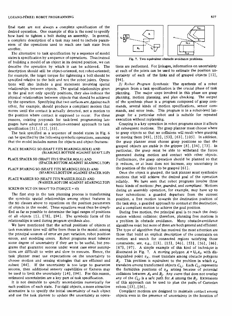
LOZANO-P~REZ: ROBOT PROGRAMMING 831
final state are not always a complete specification of the desired operation. One example of this is the need to specify how hard to tighten a bolt during an assembly. In general, a complete description of a task may need t o include param- eters of the operations used to reach one task state from another.
The alternative to task specification by a sequence of model states is specification by a sequence of operations. Thus instead of building a model of an object in its desired position, we can describe the operation by which it can be achieved. The description should still be object-oriented, not robot-oriented; for example, the target torque for tightening a bolt should be specified relative to the bolt and not the robot joints. Opera- tions will also include a goal statement involving spatial relationships between objects. The spatial relationships given in the goal not only specify positions, they also indicate the physical relationships between objects that should be achieved by the operation. Specifying that two surfaces are Against each other, for example, should produce a compliant motion that moves until the contact is actually detected, not a motion to the position where contact is supposed to occur. For these reasons, existing proposals for task-level programming lan- guages have adopted an operation-centered approach to task specification [ 5 1 ] , [ 5 2 ] , [55].
The task specified as a sequence of model states in Fig. 6 can be specified by the following symbolic operations, assuming that the model includes names for objects and object features:
PLACE BEARING1 SO (SHAFT FITS BEARING1.HOLE) AND (BEARING1.BOTTOM AGAINST SHAFT'.LIP)
PLACE SPACER SO (SHAFT FITS SPACER.HOLE) AND (SPACER.BOTTOM AGAINST BEARING1.TOP)
PLACE BEARING SO (SHAFT FITS BEARING2.HOLE) AND (BEARING2.BOTTOM AGAINST SPACER.TOP)
PLACE WASHER SO (SHAFT FITS WASHER.HOLE) AND (WASHER.BOTTOM AGAINST BEARING2.TOP)
SCREW-IN NUT ON SHAFT TO (TORQUE = to)
The first step in the task planning process is transforming the symbolic spatial relationships among object features in the SO clauses above to equations on the position parameters of objects in the model. These equations must then be simpli- fied as far as possible to determine the legal ranges of positions of all objects [ 11, [78] , [94] . The symbolic form of the relationships is used during program synthesis also.
We have mentioned that the actual positions of objects at task execution time will differ from those in the model; among the principal sources of error are part variation, robot position errors, and modeling errors. Robot programs must tolerate some degree of uncertainty if they are to be useful, but pro- grams that guarantee success under worst case error assump- tions are difficult to write and slow to execute. Hence, the task planner must use expectations on the uncertainty to choose motion and sensing strategies that are efficient and robust [44]. If the uncertainty is too large to guarantee success, then additional sensory capabilities or fixtures may be used to limit the uncertainty [ 1.11, [ 941. For this reason, estimated uncertainties are a key part of task specification.
It is not desirable to specify uncertainties numerically for each position of each state. For rigid objects, a more attractive alternative is to specify the initial uncertainty of each object and use the task planner to update the uncertainty as opera-
VI
I I I I I Fig. 7. Two equivalent obstacle avoidance problems.
tions are performed. For linkages, information on uncertainty at each of the joints can be used to estimate the position un- certainty of each of the links and of grasped objects 1121, [941.
3) Robo t Program Synthesis: The synthesis of a robot program from a task specification is the crucial phase of task planning. The major steps involved in this phase are grasp planning, motion planning, and plan checking. The output of the synthesis phase is a program composed of grasp com- mands, several kinds of motion specifications, sensor com- mands, and error tests. This program is in a robot-level lan- guage for a particular robot and is suitable for repeated execution without replanning.
Grasping is a key operation in robot programs since it affects all subsequent motions. The grasp planner must choose where to grasp objects so that no collisions will result when grasping or moving them [491, [521, [531, [631, [1051. Inaddition, the grasp planner must choose grasp positions so that the grasped objects are stable in the gripper [81, [341, 1731. In particular, the grasp must be able to withstand the forces generated during motion and contact with other objects. Furthermore, the grasp operation should be planned so that it reduces, or at least does not increase, any uncertainty in the position of the object to be grasped [ 6 1 1 .
Once the object is grasped, the task planner must synthesize motions that will achieve the desired goal of the operation reliably. We have seen that robot programs involve three basic kinds of motions: free, guarded, and compliant. Motions during an assembly operation, for example, may have up to four submotions: a guarded departure from the current position, a free motion towards the destination position of the task step, a guarded approach to contact at the destination, and a compliant motion to achieve the goal position.
During free motion, the principal goal is to reach the desti- nation without collision; therefore, planning free motions is a problem in obstacle avoidance. Many obstacle-avoidance algorithms exist but none of them are both general and efficient. The type of algorithm that has received the most attention are those that build an explicit description of the constraints on motion and search for connected regions satisfying those cmstraints; see, e.g., [131, I151, [461, [531, 1561, [861, [87] , [97] . A simple example of this kind of technique is illustrated in Fig. 7. A moving polygon A = UiAi, with dis- tinguished point U A , must translate among obstacle polygons Bi. This problem is equivalent to the problem in which UA translates among transformed objects C~,J . Each Ci,i represents the forbidden positions of UA arising because of potential collisions between Ai and Bi. Any curve that does not overlap any of the Cki is a safe path for A among the Bi. Extensions of this approach can be used to plan the paths of Cartesian robots 1531, [56l.
Compliant motions are designed to maintain contact among objects even in the presence of uncertainty in the location of

PROCEEDINGS OF THE IEEE, VOL. 71, NO. 7, JULY 1983
4: U
Fig. 8. Ambiguous results of a guarded motion under uncertainty.
the objects; see [62] for a review. The basic idea is that the robot can only control its position along the tangent to a surface” without violating the constraints imposed by the surface. In the direction normal to the surface, the robot can only control forces if it is to guarantee contact with the sur- face. The planning of compliant motions, therefore, requires models that enable one to deduce the directions which require force control and those that require position control. This planning is most complicated when the robot interacts with other mechanisms [ 601.
Compliant motions assume that the robot is already in con- tact with an object; guarded motions are used to achieve the initial contact with an object [ 1041. A guarded motion in the presence of uncertainty, however, does not allow the program to determine completely the relative position of the objects, several outcomes may be possible as a result of the motion (see Fig. 8). A strategy, composed of compliant motions, guarded motions, and sensing must be synthesized to reliably achieve the specified goal. In particular, for the example in Fig. 8, the strategy must guarantee that the desired final state is achieved no matter which of the possible states actually is reached [ 141 , [47 ] , [52 ] , [56 ] , [94 ] .
Most of the difficulty in doing motion synthesis stems from the need t o operate under uncertainty in the positions of the objects and of the robot. These individual uncertainties can be modeled and their combined effect on positions computed. The requirements for successful completion of task steps can be used t o choose the strategy for execution, e.g., an insertion with large clearance may be achieved by a positioning motion, while one with little clearance might require a guarded motion to find the surface followed by a compliant motion [ 141, [ 741. In general, the uncertainty in the position of objects may be too large to guarantee that some motion plan will succeed. In these cases, noncontact sensing such as vision may be used at run-time to reduce the uncertainty. The task planner must decide when such information is likely to be useful, given that the sensory information also will be subject to error. This phase of task planning has been dubbed plan checking; it is treated in detail in [ 141.
Task planning, as described above, assumes that the actual state of the world will differ from the world model, but only within known bounds. This will not always be the case however; objects may be outside the bounds of estimated uncertainty, objects may be of the wrong type, or objects
may be absent altogether. In these cases and many others, the synthesized programs will not have the expected result; the synthesized program should detect the failure and either correct it or discontinue the operation. Error detection will avoid possible damage to the robot and other parts of the environment. Hence, an important part of robot program synthesis should be the inclusion of sensory tests for error detection. Error detection and correction in robot programs is a very difficult problem, but one for which very little research is available [ 141, [ 291, [ 521.
4) Task-Level Systems: A number of task-level language systems have been proposed, but no complete system has been implemented. We saw above that many fundamental problems remain unsolved in this area; languages have served primarily as a focus of research, rather than as usable systems.
The Stanford Hand-Eye system [ 221 was the first of the task- level system proposals. A subset of this proposal was imple- mented, namely Move-Instance [ 731, a program that chose stable grasping positions on polyhedra and planned a motion to approach and move the object. The planning did not involve obstacle avoidance (except for the table surface) or the plan- ning of sensory operations.
The initial definition of AL [24] called for the ability to specify models in AL and to allow specification of operations in terms of these models. This has been the subject of some research [ 51, [ 941, but the results have not been incorporated into the existing AL system. Some additional work within the context of Stanford’s Acronym system [12] has dealt with planning grasp positions [751, but AL has been viewed as the target language rather than the user language.
Taylor [ 941 discusses an approach to the synthesis of sensor- based AL programs from task-level specifications. Taylor’s method relies on representing prototypical motion strategies for particular tasks as parameterized robot programs, known as procedure skeletons. A skeleton has all the motions, error tests, and computations needed to carry out a task, but many of the parameters needed to specify motions and tests remain to be specified. The applicability of a particular skeleton t o a task depends on the presence of certain features in the model and the values of parameters such as clearances and uncer- tainties. Choices among alternative strategies for a single operation are made by first computing the values of a set of parameters specific to the task, such as the magnitude of un- certainty region for the peg in peg-in-hole insertion, and then using these parameters to choose the “best,” e.g., fastest, strategy. Having chosen a strategy, the planner computes the additional parameters needed to specify the strategy motions, such as grasp positions and approach positions. A program is produced by inserting these parameters into the procedure skeleton that implements the chosen strategy.
The approach to strategy synthesis based on procedure skeletons assumes that task geometry for common subtasks is predictable and can be divided into a manageable number of classes each requiring a different skeleton. This assumption is needed because the sequence of motions in the skeleton wiU only be consistent with a particular class of geometries. The assumption does not seem to be true in general. As an example, consider the tasks shown in Fig. 9. A program for task A could perhaps be used to accomplish tasks B and C, but it

LOZANO-PEREZ: ROBOT PROGRAMMING a39
€7 U T T
be slow when compared to mechanical means of reducing uncertainty.
Both of these problems are receiving significant attention today. When they are effectively overcome, the need for good robot programming tools will be acute.
(a) 0 ) (C) The main goal of this paper has been to assess the state of the Fig. 9 . Similar peg-in-hole tasks which require different strategies. art in robot programming compared with the requirements of
sophisticated robot tasks. Our conclusion is that all of the
trasts to an approach which derives the strategy directly from consideration of the task description [ 561. In advanced sys- tems, both types of approaches are likely to play a role.
The LAMA system was designed at MIT [521 , [551 as a task-level language, but only partially implemented. LAMA formulated the relationship of task specification, obstacle avoidance, grasping, skeleton-based strategy synthesis, and error detection within one system. More recent work at MIT has explored issues in task planning in more detail outside of the context of any particular system [ 13 1, [ 141, [531, [571, [601, [611.
AUTOPASS, a t IBM [ 5 1 ] , defined the syntax and semantics of a task-level language and an approach to its implementation. A subset of the most general operation, the PLACE statement, was implemented. The major part of the implementation effort focused on a method for planning collision-free paths for Cartesian robots among polyhedral obstacles [ 561, [ 1001 .
RAPT [77] is an implemented system for transforming symbolic specifications of geometric goals, together with a program which specifies the directions of the motions but not their length, into a sequence of end-effector positions. RAPT’S emphasis has been primarily on task specification; it does not deal with obstacle avoidance, automatic grasping, or sensory operations.
Some robot-level language systems have proposed extensions to allow some task-level specifications. LM-GEO [471 is an implemented extension to LM [48] which incorporates sym- bolic specifications of destinations. The specification of ROBEX [ 9 9 ] includes the ability to automatically plan collision-free motions and to generate programs that use sensory information available during execution. A full-blown ROBEX, including these capabilities, has not been imple- mented.
The deficiencies of existing methods for geometric reasoning and sensory planning have prevented implementation of a complete task-level robot programming system. There has, however, been significant progress towards solving the basic problems in task planning; see [ 541 for a review.
V. DISCUSSION AND CONCLUSIONS Existing robot programming systems have focused primarily
on the specification of sequences of robot configurations. This is only a small aspect of robot programming, however. The central problem of robot programming is that of speci- fying robot operations so that they can operate reliably in the presence of uncertainty and error. This has long been recognized in research labs, but until very recently has found little acceptance in industrial situations. Some key reasons for this difference in viewpoint are:
1) the lack of reliable and affordable sensors, especially those already integrated into the control and programming systems of a robot;
2) existing techniques for sensory processing have tended t o
existing robot systems fall short of meeting the requirements we can identify today.
The crucial problem in the development of robot program- ming languages is our lack of understanding of the basic issues in robot programming. The question of what basic set of operations a robot system should support remains unanswered. Initially, the only operation available was joint motion. More recently, Cartesian motion, sensing, and, especially, compliance have been recognized as important capabilities for robot systems. In future systems, a whole range of additional operations and capabilities are to be expected:
1) Increasing integration o f sensing and motion: More efficient and complete implementations of compliant motions are a key priority.
2 ) Complete object models as a source o f da ta fo r sensor interfaces and trajectory planning: Existing partial models of objects are inadequate for most sensing tasks; they are also limited as a source of path constraints. Surface and volume models, together with appropriate computational tools, should also open the way for more natural and concise robot programs.
3 ) Versatile trajectow specifications: Current systems over- specify trajectories and ignore dynamic constraints on motion. Furthermore, they severely restrict the vocabulary of path shapes available to users. A mechanism such as functionally defined motion can make it easy to increase the repertoire of trajectories available to the user.
4 ) Coordination of multiple parallel tasks: Current robot systems have almost completely ignored this problem, but increasing use of robots with more thansix degrees of freedom, grippers with twelve or more degrees of freedom, multiple special-purpose robots with two or three degrees of freedom, and multiple sensors will make the need for coordination mechanisms severe.
5) The IIO, control, and synchronization capabilities o f general-purpose computer programming Ianguages: A key problem in the development of robot languages has been the reluctance, on the part of users and researchers alike, to accept that a robot programming language must be a sophisti- cated computer language. The evidence seems to point to the conclusion that a robot language should be a superset of an established computer programming language, not a subset.
The developments should be matched with continuing efforts at raising the level of robot programming towards the task level. By automating many of the routine programming func- tions, we can simplify the programming process and thereby expand the range of applications available to robot systems.
One problem that has plagued robot programming research has been the significant “barriers to entry” to experimen-tal research in robot programming. Because robot control sys- tems on available robots are designed to be stand alone, every research group has to reimplement a robot control system from the ground up. This is a difficult and expensive operation. It is t o be hoped that commercial robots of the future will be

840 PROCEEDINGS OF THE IEEE, VOL. 71, NO. 7, JULY 1983
designed with a view towards interfacing to other computers, rather than as stand-alone systems. This should greatly stimu- late development of the sophisticated robot programming systems that we will surely need in the future.
ACKNOWLEDGMENT
Many of the ideas discussed in this paper have evolved over the years through discussions with many people, too numerous to mention. The author has benefited, especially, from extensive discussions with M. Mason and R. Taylor. He thanks both of them for their time and their help. The initial moti- vation for this paper and many of the ideas expressed herein arose as a result of the “Workshop on Robot Programming Languages” held at MIT in January 1982, sponsored by ONR. The author is indebted to all the participants of the workshop. The following people read drafts and provided valuable com- ments: M. Brady, R. Brooks, S. Buckley, E. Crimson, J.
, Hollerbach, B. Horn, M. Mason, and R. Paul. The author also i wishes to thank the two referees for their suggestions. ~
REFERENCES [ 11 A. P. Ambler and R. J. Popplestone, “Inferring the positions of
bodies from specified spatial relationships,” Artificial Zntell., VOL 6, no. 2, pp. 157-174, 1975.
[ 21 A. P. Ambler, R. J. Popplestone, and K. G. Kempf, “An experi- ment in the Offline Programming of Robots,” in Roc. 12th Znt. Symp. on Industrial Robots (Paris, France, June 1982),
[3] ASEA ‘‘Industrial robot system,” ASEA AB, Sweden, Rep.
[4] A. Baer, C. Eastman, and M. Henrion, “Geometric modem: A survey,” Computer Aided Des., voL 11, no. 5, pp. 253-272, Sept. 1979.
[5] T. 0. Binford, ‘The AL language for intelligent robots,” in Proc. ZRLA Sem. on Languages and Methods o f Programming Industrial Robots (Rocquencourt, France, June 1979), pp. 73- 87.
[6] R. Bolles and R. P. Paul, ‘The use of sensory feedback in a programmable assembly system,” Artificial Intelligence Labo- ratory, Stanford University, Rep. AIM 220, Oct 1973.
[7] S. Bonner and K. G. Shin, “A comparative study of robot languages,”ZEEE Computer, pp. 82-96, Dec. 1982.
[8] J. M. Brady, “Parts description and acquisition using vision,” Proc. SPZE, May 1982.
[9] -, “Trajectory planning,” in Robot Motion: Planning and Control, M. Brady et al., Eds Cambridge, MA: MIT Press, 1983.
[ 101 I. Braid, “New directions in geometric modelug” presented at the CAM-I Workshop on Geometric Modeling, Arlington, TX, 1978.
[ 111 P. Brinch Hansen, “The programming language concurrent Pascal,” ZEEE Trans. Software Eng., vol. SE-1, no. 2, pp. 199-
pp. 491-502.
YB 110-301 E.
207, June 1975. 1121 R. A. Brooks. “Symbolic reasonim among 3-D modelsand 2-D L - 1
images,” Artij?ciaiInteIl., voL 17, ip . 2851348, 1981. [ 131 -, “Solving the find-path problem by representing free space
as generalized cones,” Artificial Intelligence Lab., MIT, AI Memo 674, May 1982a.
[14] -, “Symbolic error analysis and robot planning,” Znt. J. Robotics R e s , voL 1, no. 4, 1983.
[15] R. A. Brooks and T. Lozano-Pbrez, “A subdivision algorithm in configuration space for findpath with rotation,” ZEEE naris. Syst., Man, Cybem, voL SMC-13, pp. 190-197, Mar./Apr. 1983.
[16] J. A. Darringez and M. W. Blasgen, “MAPLE: A high level lan- guage for research in mechanical assembly,” IBM T. J. Watson Res. Center, Tech. Rep. RC 5606, Sept. 1975.
[ 171 E. W. Dijkstra, ‘To-operating sequential processes,” in Program- ming Languages, F. Genuys, Ed. New York Academic Press,
[ 181 H. A. Ernst, “A computer-controlled mechanical hand,” Sc.D. thesis, Massachusetts Institute of Technology, Cambridge, 1961.
[19] R. C. Evans, D. G. Gamett, and D. D. Grossman, “Software
1968, pp. 43-112.
Watson Res Center, Tech. Rep. RC 6210, May 1976. system for a computer controlled manipulator,” IBM T. J.
[20] D. Falek and M. Parent, “An evolutive language for an intelli- gent robof”Zndust. Robot, pp. 168-171, Sept. 1980.
[ 211 I. D. Faux and M. J. Pratt Computational Geometry for Design and Manufacture. Chichester, England: Ellis Horwood Press, 1979.
[22] J. Feldman et al., “The Stanford Hand-Eye Project,” in Proc. FirstZJCAZ (London, England, Sept. 1971), pp. 350-358.
[23] R. A. Finkel, “Constructing and debugging manipulator pro- grams,” Artificial Intelligence Lab., Stanford Univ., Rep. AM 284, Aug. 1976.
[24] R. Finkel, R. Taylor, R. Bolles, R. Paul, and J. Feldman, “AL, A programming system for automation,” Artificial Intelligence Lab., Stanford Univ., Rep. AIM-177, Nov. 1974.
[25] J. W. Franklin and G. J. Vanderbrug, “Programming vision and robotics systems with RAIL,” SME Robots VI, pp. 392-406, Mar. 1982.
[ 261 General Electric “GE Allegro documentation,” General Electric Corp., 1982.
[27] C. C. Geschke, “A system for programming and controllug sensor-based manipulators,” Coordinated Sci. Lab., Univ. of Illinois, Urbana, Rep. R-837, Dec. 1978.
[28] G. Gini, M. Gini, R. Gini and D. Giuse, “Introducing software systems in industrial robots,” in Proc. 9th Znt. Symp. on Zndus- trial Robots (Washington DC, Mar. 1979), pp. 309-321.
[29] G. Gin4 M. Gini, and M. Somalvico, “Determining and nonde- terministic programming in robot systems,” obernen’cs and Systems, voL 12, pp. 345-362, 1981.
[30] G. J. Gleason and G. J. Agin, “A modular vision system for sensor-controlled manipulation and inspection,” in Proc. 9th Znt Symp. on Zndusrrial Robots (Washington, DC, Mar. 1979),
(311 T. Goto, K. Takeyasu, and T. Inoyama “Control algorithm for precision insert operation robots,” ZEEE Trans. Systems, Man, Cybern., voL SMC-10, no. 1, pp. 19-25, Jan. 1980.
[32] D. D. Grossman, “Programming a computer controlled manip ulator by guiding through the motions,” IBM T. J. Watson Res Cen., Res. Rep. RC6393, 1977 (Declassified 1981).
[33] D. D. Grossman and R. H. Taylor, “Interactive generation of object models with a manipulator,” ZEEE Trans. Systems, Man, Cybern., voL SMC-8, no. 9, pp. 667-679, Sept. 1978.
[34] H. Manafusa and B. Asada, “Mechanics of gripping form by artiiicial fmgers,” Trans. SOC. Znstrum. Contr. Eng., vol. 12, no. 5, pp. 536-542, 1976.
[35] -, “A robotic hand with elastic fingers and its application to assembly process,” presented at the IFAC Symp. on Informa- tion and Control Problems in Manufacturing Technology, Tokyo, Japan, 1977.
[36] L. D. Harmon, “Automated tactile sensing,” Robotics Res., voL 1, no. 2, pp. 3-32, Sumer 1982.
[37] T. Hasegawa, “A new approach to teaching object desicriptions for a manipulation environment,” in Proc. 12th Znt. Symp. on Industrial Robots (Paris, France, June 1982), pp. 87-97.
[38] W. B. Heginbotham, M. Dooner, and K. Case, “Robot applica- tion simulation,”Zndus. Robot, pp. 76-80, June 1979.
[39] C.A.R. Hoare, ‘Towards a theory of parallel programming,” in Operating Systems Technqiuer New York: Academic Press,
[40] -, “Communicating sequential processes,” Commun. ACM, voL 12, no. 8, pp. 666-677, Aug. 1978.
[41] H. R. Holt, “Robot decision making,” Cincinnati Milacorn Inc., Rep. MS77-751, 1977.
[42] J. D. Ichbiah, Ed. Reference Manual for the A& Programming Language, US Department of Defense, Advanced Research Projects Agency, 1980.
[43] H. Inoue, “Computer controlled bilateral manipulator,” Bull. JSME, voL 14, no. 69, pp. 199-207,1971.
[44] -, “Force feedback in precise. assembly tasks,” Artificial Intelligence Lab., MIT, Rep. AIM-308, Aug 1974.
[45] T. Ishida, “Force control in coordination of two arms,” Pre- sented at the Fifth Int Cod. on Artificial Intelligence, Cam-
pp. 57-70.
1972, pp. 61-71.
bridge, MA, Aug. 1977. -
1461 H. B. Kuntze and W. Schill. “Methods for collision avoidance in L .
computer controlled industrial robots,” in Roc. 12th Znt. Symp. on ZnmCstrial Robots (Paris, France, June 1982), pp. 519-530.
[47] J. C. Latombe, “Equipe intelligence artifkielle et robotique: Etat d’avancement des recherches,” Laboratoire IMAG, Grenoble, France, Rep. RR 291, Feb. 1982.

LOZANO-PEREZ: ROBOT PROGRAMMING 84 1
[48] J. C. Latombe and E. Mazer, “LM: A high-level language for controlling assembly robots,” presented at the Eleventh Int. Symp. on Industrial Robots, Tokyo, Japan, Oct. 1981.
[49] C. Laugier, “A program for automatic grasping of objects with a robot arm,” presented at the Eleventh Int. Symp. onhdustrial Robots, Tokyo, Japan, Oct 1981.
[50] M. A. Lavin and L. I. Lieberman, “AML/V: An industrial ma- chine vision pronramming system,” Int. J. Robotics Res., - .
voL 1, no. 3, 1982. 1511 L. I. Lieberman and M. A. Weslev. “AUTOPASS: An automatic L A
programming system for computer controlled mechanical assembly,”IBMJ. Res. Devel.,voL 21, no. 4, pp. 321-333, 1977.
[52] T. Lozano-P6rez, “The design ofa mechanicalassembly system,” Artiticial Intelligence Lab., MIT, AI Tech. Rep. TR 397,1976.
[53] -, “Automatic planning of manipulator transfer movements,” IEEE Trans. Systems, Man, Cybern., vol. SMC-11, no. 10, pp. 681-698, Oct. 1981.
[54] -, “Task planning,” in Robot Motion: Planning and Control, M. Brady et al. Eds Cambridge. MA: MIT Press, 1983.
[55] T. Lozano-Ptrez and P. H. Winston, “LAMA: A language for automatic mechanical assembly,” in Proc. 5th Int, Joint Coni on Artificial Intelligence (Massachusetts Institute of Technology, Cambridge, MA, Aug. 1977), pp. 710-716.
[56] T. Lozano-P&rez and M. A. Wesley, “An algorithm for planning collision-free paths among polyhedral obstacles,” Commun. ACM, vol. 22. no. 10, pp. 560-570, Oct. 1979.
[57] T. Lozano-Pdrez, M. T. Mason, and R. H. Taylor, “Automatic synthesis of fme-motion strategies for robots,” Artificial In- telligence Lab., MIT, July 1983.
[58] McDonnell Douglas, Inc “Robotic System for Aerospace Batch Manufacturing,” McDonnell Douglas, Inc, Feb. 1980.
[59] G. Markowsky and M. A. Wesley, “Fleshing out wire frames,” IBMJ. Res. Devel., vol. 24, no. 5, Sept. 1980.
[60] M. T. Mason, “Compliance and force control for computer controlled manipulators,” IEEE Trans. Systems, Man Cybern., voL SMC-11, no. 6, pp. 418-432, June 1981.
[61] -, “Manipulator grasping and pushing operations,” Ph.D. dissertation, Dep. Elec. Eng. Comput Sci., MIT, 1982.
[62] -, “Compliance,” in Robot Motion: Planning and Control, M. Brady et al., Eds. Cambridge, MA: MIT Press, 1983.
[63] D. Mathur, “The grasp planner,” Dep. Artificial Intelligence, Univ. of Edinburgh, DAI Working Paper 1, 1974.
[64] E. Mazer, “LM-Geo: Geometric programming of assembly robots,” Laboratoire IMAG, Grenoble, France, 1982.
[65] J. M. Meyer, “An emulation system for programmable sensory robots,”ZBMJ. Res. Devel,, voL 25, no. 6, Nov. 1981.
[66] M. Minsky, “Manipulator design vignettes,” MIT Artificial Intelligence Lab., Rep. 267, Oct. 1972.
[67] S . Mujtaba and R. Goldman, “AL user’s manual,” Stanford Artificial Intelligence Lab., Rep. AIM 323, Jan. 1979.
[68] E. Nakano, S. Ozaki, T. Ishida, and I. Kato “Cooperational control of the anthropomorphous manipulator ‘MELAR”,” in Proc. 4th Znt. Symp. on Industrial Robots (Tokyo, Japan,
[69] N. Nilsson, “A mobile automation: an application of artificial intelligence techniques,” in Proc. Znt. Joint ConL on Artificial Intelligence, pp. 509-520, 1969.
[70] -, Principles of Artificial Intelligence. CA: Tioga Pub., 1980.
[71] M. S . Ohwovoriole and B. Roth, “A thoery of parts mating for
Poland, 1981. assembly automation,” presented at Ro.Man.Sy.-81, Warsaw,
[72] W. T. Park, “Minicomputer software organization for control of industrial robots,” presented at the Joint Automatic Control C o d , San Francisco, CA, 1977.
[73] R. P. Paul, “Modeling, trajectory calculation, and servoing of a
Rep. AIM 177, Nov. 1972. controlled arm,” Stanford Univ., ATtificial Intelligene Lab.,
[ 741 -, “WAVE: A model-based language for manipulator control,” Zndust. Robot, Mar. 1977.
[75] -, Robot Manipulators: Mathematics, Programming, and Control. Cambridge, MA: MIT Press, 1981.
[76] R. P. Paul and B. Shimano, “Compliance and control,” inProc. 1976 Joint Automatic Control Conf:, pp. 694-699,1976.
[77] R. J. Popplestone, A. P. Ambler, and I. Bellos, “RAPT, A lan- guage for describing assemblies,” Indust. Robot, voL 5 , no. 3,
[78] - , “An interpreter for a language for describing assemblies,”
.,
1974), pp. 251-260.
pp. 131-137,1978.
Artificial Znteni, voL 14, no. 1, pp. 79-107, 1980.
[79] M. H. Raiert and J. J. Craig, “Hybrid position/force control of manipulators,” ASME J. Dynamic Syst., Meas., Con tr., voL 102, pp. 126-133, June 1981.
[80] A.A.G. Requicha, “Representation of rigid solids: Theory,
464, Dec. 1980. methods, and systems,” Comput. Sun?, vol. 12, no. 4 pp. 437-
[81] C. F. Ruoff, “TEACH-A concurrent robot control language,” inProc. ZEEECOMPSAC(Chicago, IL, Nov. 1979), pp. 442-445.
[82] -, “An advanced multitasking robot system,”Zn&st. Robot, June 1980.
[83] J. K. Salisbury, “Active stiffness control of a manipulator in Cartesian coordinates,” presented at the IEEE Conf. on Decision and Control, Albuquerque, N M , Nov. 1980.
[84] J. K. Salisbury and J. J. Craig, “Articulated hands: Force con- trol and kinematicissues,”RoboticsRes., vol. 1, no. 1, pp. 4-17, 1982.
[85] M. Salmon, “SIGLA: The Olivetti SIGMA robot programming language,” presented at the Eight Int. Symp. on Industrial Robots, Stuttgart, West Germany, June 1978.
[ 861 J. T. Schwartz and M. Shark, “On the piano movers problem I: The case of a two-dimensional rigid polygonal body moving amidst polygonal barriers,” Dep. Comput. Sci., Courant Inst. Math. Sci., NYU, Rep. 39, Oct. 1981.
[ 871 - , “On the piano movers problem 11: General properties for computing topological properties of real algebraic manifolds,” Dep. Comput. ScL, Courant Inst. Math. Sci., NYU, Rep. 41, Feb. 1982.
I881 B. Shimano, “The kinematic design and force control of com- puter controlled manipulators,” Artificial Intelligence Lab., Stanford Univ., Memo 313, Mar. 1978.
[89] -, “VAL: An industrial robot programming and control system,” in Proc. ZRIA Sem. on Languages and Methods of Pro- gramrninn Zndusmal Robots (Rocquencourt, France. June 1979), pi . 47-59.
- -
1901 D. Silver. “The littler robot svstem.” MIT Artificial Intellieence . > Lab., Rep. AIM 273, Jan. 1973. ‘
[91] B. I. Soroka, “Debugging robot programs with a simulator,” presented at the SME CADCAM-8, Dearborn, MI, Nov. 1980.
[92] P. D. SummersandD. D. Grossman, “XPROBE: Anexperimental system for programming robots by example,” IBM T. J. Watson Res. Center, Rep., 1982.
[93] K. Takase, R. P. Paul, and E. J. Berg, “A structured approach to robot programming and teaching,” presented at the IEEE COMPSAC, Chicago, IL, Nov. 1979.
[94] R. H. Taylor, “The synthesis of manipulator control programs from task-level specifications,” Ph.D. dissertation, Artificial Intelligence Lab., Stanford Univ., Rep. AIM-282, July 1976.
[95] -, “Planning and execution of straight-line manipulator trajectories,” ZBM J. Res. Develop., vol. 23. pp. 424-436, 1979.
[96] R. H. Taylor, P. D. Summers, and J. M. Meyer, “AML: A manu- facturing language,”Robotics Res., vol. 1, no. 3, Fall 1982.
[97] S . M. Udupa, “Collision,detection and avoidance in computer controller manipulators, presented at the Fifth Int. Joint Conf. on Artificial Intelligence, MIT, 1977.
[98] Unimation Inc. “User’s guide to VAL: A robot programming and control system,” Unimation Inc., Danbury, CT, version 12, June 1980.
[99] M. Weck and D. Zuhlke, “Fundamentals for the development of a high-level programming language for numerically controlled industrial robots,” presented at the AUTOFACT West, Dearborn, MI, 1981.
[ 1001 M. A. Wesley et al., “A geometric modeling system for automated
Y
mechanical assembly,”jBMJ. Res. Devel., vol. 24, no. 1 pp. 64- 74, Jan. 1980.
[ l o l l D. E. Whitney, “Force feedback control of manipulator fine motions,”J. Dynamic Syst., Meas., Contr., pp. 91-97, June 1977.
[lo21 -, “Quasi-static assembly of compliantly supported rigid parts,” J. Dynamic Syst., Meas., Con-tr., vol. 164, no. 1, pp. 65-77, MU. 1982.
[lo31 W. M. Wichman, “Use of optical feedback in the computer control of an a m , ” Artificial Intelligence Lab., Stanford Univ., Rep. AIM 55, Aug. 1967.
[lo41 P. M. Will and D. D. Grossman, “An experimental system for computer controlled mechanical assembly,” ZEEE Trans. Comput., vol. C-24, no. 9, pp. 879-888, 1975.
[lo51 M. Wingham, “Planning how to grasp objects in a cluttered environment,” M.Ph. thesis, Edinburgh Univ., Edinburgh, Scotland, 1977.