Embed Size (px)
Citation preview
1 Copyright © 20xx by WEENTech
Proceedings of the Global Conference on Energy and Sustainable Development GCESD2015
February 24-26, 2015, Technology Park, Coventry University Coventry, UK
GCESD8615
CFD predictions of Swirl burner aerodynamics with variable outlet configurations
Hesham Baej1
College of Physical Sciences and Engineering, Cardiff University
Nick Syred3
College of Physical Sciences and Engineering, Cardiff University
Phil Bowen5
College of Physical Sciences and Engineering, Cardiff University
Agustin Valera-Medina2
College of Physical Sciences and Engineering, Cardiff University Richard March
4
College of Physical Sciences and Engineering, Cardiff University
ABSTRACT
Swirl stabilised combustion is one of the most widely used
techniques for flame stabilisation in gas turbine combustors.
Lean premixed combustion systems allow the reduction of NOx
coupled with fair flame stability. The swirl mechanism
produces an aerodynamic region known as central recirculation
zone (CRZ) providing a low velocity region where the flame
speed matches the flow velocity, thus anchoring the flame
whilst serving to recycle heat and active chemical species to the
root of the former. Another beneficial feature of the CRZ is the
enhancement of the mixing in and around this region. However,
the mixing and stabilisation processes inside of this zone have
shown to be extremely complex. The level of swirl, burner
outlet configuration and combustor expansion are very
important variables that define the features of the CRZ.
Therefore, in this paper swirling flame dynamics are
investigated using computational fluid dynamics (CFD) with
commercial software (ANSYS). A new generic swirl burner
operated under lean-premixed conditions was modelled. A
variety of nozzles were analysed using several gaseous blends
at a constant power output. The investigation was based on
recognising the size and strength of the central recirculation
zones. The dimensions and turbulence of the Central
Recirculation Zone were measured and correlated to previous experiments. The results show how the strength and size of the
recirculation zone are highly influenced by the blend and infer
that it is governed by both the shear layer surrounding the
Central Recirculation Zones (CRZ) and the gas composition.
NOMENCLATURE
U Axial velocity [m/s]
U’ Fluctuating axial velocity [m/s]
W Tangential velocity [m/s]
ρ Density [kg/m3]
r Radius [m]
n Number of products
𝑌𝑖 Mass fraction of product species i
𝑌𝑖,𝑒𝑞 Equilibrium mass fraction of product
species i
𝜌𝑢 density of burnt mixture
𝑈𝑡 turbulent flame speed
A model constant
u’ root mean square (RMS) velocity (m/s)
Ul laminar flame speed
α thermal diffusivity (m2/s)
𝑙𝑡 turbulent length scale (m)
𝜏𝑡 turbulent time scale (s)
𝜏𝑐 chemical time scale (s)
Sh,rad the heat losses due to radiation
Sh,chem the heat gains due to chemical reactions
Sc normalized average rate of product
formation (s-1)
Hcomb heat of combustion for burning 1 kg of
fuel (J/kg)
Yfuel fuel mass fraction of unburnt mixture
Gk The generation of turbulence kinetic
energy due to mean velocity gradients
𝐺𝜔 represents the generation of 𝜔
Г𝜔 the effective diffusivity of 𝜔
Г𝑘 the effective diffusivity of k
Yk represent the dissipation of k due to
turbulence
𝑌𝜔 represent the dissipation of 𝜔 due to
turbulence
𝐷𝜔 represents the cross-diffusion term1
𝑆𝑘, 𝑆𝜔 are user-defined source terms
C the mean reaction progress variable
Sct turbulent Schmidt number
Sc reaction progress source term (S^(-1))
INTRODUCTION
A proved technology to reduce the impact of NOx is the use of
lean premixing with swirl stabilized combustion. Swirling flow
technologies have shown to give high flame stability taking
advantage of coherent structures such as corner and central
recirculation zones which anchor the flame, recirculating hot
products and active chemical species whilst also increasing
their residence time, allowing the use of low equivalence ratios
thus giving lower flame temperatures and NOx emissions [1].
2 Copyright © 20xx by WEENTech
However, premixed combustion is not perfect because fuel and
air mix just before entering the combustion chamber, thus
leading to a significant degree of un-mixedness. These create
complex instabilities which would feedback into the mixing-
reaction combustion process. Combustion instabilities remain a
critical issue limiting the development of low emission, lean
premixed gas turbine combustion systems. Strong efforts are
currently undertaken for the numerical simulation of swirl
stabilized flames with the intention of designing improved gas
turbine combustors [2-3].
The biggest challenge to fuel-flexibility of most combustors is
the large differences between natural gas and the proposed
replacement fuels. Moreover, gas turbines must meet the
current emissions regulations, which often mean running very
near lean blowoff. However, blowoff continues to be a
phenomenon that is difficult to predict across reactor types and
fuel compositions. To describe the lean blowoff behaviour of
swirl combustors under various fuel compositions, correlations
have to be determined and simplified models developed to
allow the implementation of fuel flexible technologies [4].
The crucial feature of swirl burners is the formation of a central
recirculation zone (CRZ) which extends blowoff limits by
recycling heat and active chemical species to the root of the
flame in the burner exit [5-6]. Thus, the CRZ is one of the
mechanisms for flame stabilization that through an
aerodynamically decelerated region creates a point where the
local flame speed and flow velocity match [7]. A vast amount
of literature exists on measuring, correlating and predicting
blowoff limits for bluff body and swirl stabilized combustors.
There are three basic characterizations of the physical
phenomena responsible for blowoff. Longwell et al. [8]
suggested that blowoff occurs when it is not possible to balance
the rate of entrainment of reactants into the recirculation zone,
viewed as a well stirred reactor, and the rate of burning of these
gases. A different view is that the contact time between the
combustible mixture and hot gases in the shear layer must
exceed a chemical ignition time. This leads to scaling the
characteristic dimension by the recirculation zone length,
leading to a similar Da criterion [9]. Current theories are based
on a flamelet based description upon local extinction by
excessive flame stretch [10]. Flame stretching starts blowoff
with the initiation of holes in the flame, that are healed by the
same flame creating stretching in areas that otherwise would
have been unaffected. Flame will extinguish when flame stretch
rate exceeds a critical value. However, it is also recognized that
this mechanism is not the one causing the final blowoff, as it is
clear from data that the flame can withstand some extinction
[11]. Therefore, it is considered that the “critical extinction
level” must be somehow influenced by other mechanisms [8-9]. Regarding the central recirculation zone, the use of different
configurations has demonstrated that the shape and strength of
the CRZ can change drastically depending on these alterations
[12-13]. Valera-Medina et al. [13] have observed how the
change of the combustor nozzle can produce different central
recirculation zones under the same injection conditions.
Lieuwen et al [14] investigated the impact of fuel composition
on the operability of lean premixed gas turbine combustors
focusing on H2/CH4 flames. They showed that small additions
of H2 substantially enhance the mixture’s resistance to
extinction or blowoff. For example, fundamental studies show
that the extinction strain rate of methane flames is doubled with
the addition of 10% H2. Similarly, CO/CH4 flames showed a
variance in their extinction strain rate. Experiments were also
conducted using N2, H2O and CO2. They concluded that the
flame speeds of mixtures with CO2 dilution are lower than
those of mixtures diluted with chemically inert species with the
same specific heat as CO2. The CO2 dilution can lead to lower
laminar flame speeds and lower flame temperatures due to
radiative losses from the flame, which can also impact
emissions [11]. Shelil et al. [15] defined the stability limits of
flames regarding flashback and correlated it to the mean
mixture velocity at the burner exit. They determined the
flashback limits, numerically, for H2/CH4 blends ranging from
0% (pure methane) up to 100% (pure hydrogen) based on the
volumetric composition at atmospheric pressure and 300 K for
various equivalence ratios. Their results showed that the use of
up to 50% blends of methane and hydrogen causes fewer
problems with flame stability and flashback compared with the
use of pure hydrogen, as observed by Liewen et al [14].
However, there is still a considerable need for experimental and
numerical correlations of different stability phenomena and fuel
blends in gas turbines.
On the other hand, significant progress has been made in the
development of computational fluid dynamics (CFD) to
simulate the performance of practical combustion systems over
the last two decades. These models are now increasingly being
used for the evaluation of performance and to assist in the
design and development of such combustors. Reliable
predictions of the combustion and pollutant formation
processes occurring in the near burner region critically depend
on the accuracy of the turbulent flow field calculation. The
emission reduction, especially of NOx, has been the major
driver for gas turbine development in these decades. In the
fields of combustion science and engineering, CFD calculations
is now truly competitive with experiment and theory as a
research tool to produce detailed and multi-scale information
about combustion processes, playing a crucial role in the design
of environment friendly processes. In particular, gas turbine
combustion modelling, involving the interaction of many
complex physical processes such as turbulent mixing, chemical
reactions etc., comprises a range of computational and
modelling challenges [16].
The shear-stress transport (SST) k-𝜔 turbulence model is
generally employed for swirling flows. The limitations of this
model for predictions of both non-combusting (isothermal) and
combusting swirling flows, in particular, the size and strength

3 Copyright © 20xx by WEENTech
of the swirl-induced Central recirculation zone (CRZ), are well
known [15, 17].
Therefore, in this paper the CFD code Fluent is used to
simulate a swirl premixed combustion system. A three
dimensional model is used to study the flame stability and
determine the process and CRZ size close to the blowoff
phenomenon. The stability limits are defined and correlated to
both total mass flow rate and equivalence ratios. Methane and
carbon dioxide fuel blends were studied and compared with
combustion of pure methane.
NUMERICAL METHODOLOGY
CFD modelling was used to simulate the combustion of a
premixed swirl burner that uses different types of fuels. A
100kW swirl burner constructed from stainless steel was used
to examine the flame stability limits at atmospheric conditions
(1 bar, 293 K) at Cardiff University’s Gas Turbine Research
Centre (GTRC). Different nozzles were used with various
angles: 30°, 45°, 60°, 90°, with two swirl numbers of 1.05 and
1.50. A single tangential inlet (a) feeds the premixed air and
fuel to an outer plenum chamber (b) which uniformly
distributes the gas to the slot type radial tangential inlets (c).
Swirling unburned fuel then passes into the burner body (d),
then into the burner exhaust (e) where the gases pass around the
flame stabilizing central recirculation zone. The central
diffusion fuel injector (f) (which was not used for fuel during
the course of this study) extends centrally through the
combustor body to the exhaust, Figure 1.
CFD modelling is initially performed to simulate the
combustion of methane-air without/with carbon dioxide.
Laminar flame speeds were calculated for pure methane and
CH4/CO2 blends at atmospheric pressures, 300 K and various
equivalence ratios. This was done using CHEMKIN-PRO with
PREMIX code. The numerical values for the laminar flame
speeds were then fed into the CFD model. Isothermal
conditions with no combustion were used to calibrate the
system and indicate the flow pattern, although it is well known
that there are also 3D time, dependant coherent structures, thus
the results are of an indicative nature. During the simulation,
various types of solvers were investigated and conclusions
drawn as to which were the most effective. Based on the
experimental results obtained at 5.85 and 5.48 g/s total mass
flow rates, the best turbulent option for the present work was
the κ-ω SST model [11, 18-20].
Swirl combustor and burners are usually characterized by the
degree of swirl, via a swirl number (S). For this particular
project, the swirl element of 1.05 has four tangential inlets
symmetrically distributed, whilst the swirl element of 1.50 has
nine tangential inlets symmetrically distributed. The swirl
burner gives good flame stabilization, but produces a CRZ that
extends back over the central fuel injector, allowing the flame
to propagate into this region. This effect can be reduced by
fitting a divergent of the exhaust nozzle of the burner, as shown
in Figure 2, producing a different CRZ.
Figure 1. Swirl burner and schematic diagram, respectively
Figure 2. Geometrical swirl number 1.50, 1.05 and various
divergent angles nozzles, respectively.
Premixed Combustion Modelling
In premixed combustion fuel and oxidizer are mixed prior to
ignitions [18]. Combustion occurs as a flame front propagates
into the unburnt reactants. However, premixed combustion is
much more difficult than non-premixed combustion. The
reason for this is that premixed combustion usually occurs as
thin, propagating flames that stretch and contort by turbulence.
For subsonic flows, the overall rate of propagation of the flame
is determined by both the laminar flame speed and the turbulent
eddies. The laminar flame speed is determined by the rate that
species and heat diffuse upstream into the reactants and burn.
The flame front propagation is modelled by solving a transport
equation for the density-weighted mean reaction progress
variable, denoted by c [21]:
𝜕
𝜕𝑡(𝜌𝑐) + ∇. (𝜌𝑣 ⃗⃗⃗ 𝑐) = ∇. (
𝜇𝑡
𝑆𝑐𝑡∇𝑐) + 𝜌𝑆𝑐 (1)
4 Copyright © 20xx by WEENTech
The progress variable is defined as a normalized sum of the
product species,
𝑐 = ∑ 𝑌𝑖 /∑ 𝑌𝑖,𝑒𝑞
𝑛𝑖=1
𝑛𝑖=1 (2)
Based on this definitions c=0 where the mixture is unburnt and
c=1 where the mixture is burnt. And the value of c is defined as
a boundary condition at all flow inlets. It is usually specified as
either 0 (unburnt) or 1 (burnt). The mean reaction rate in
equation (4) is modelled as,
𝜌𝑆𝑐 = 𝜌𝑢𝑈𝑡 |∇𝑐| (3)
The turbulent flame speed computed from this equation
𝑈𝑡 = 𝐴 (𝑢′)3/4𝑈𝑖1/2𝛼−1/4𝑙𝑡
1/4= 𝐴𝑢′ (
𝜏𝑡
𝜏𝑐)1/4
(4)
The turbulent length scale 𝑙𝑡 is computed from
𝑙𝑡 = 𝐶𝐷 (𝑢′)3
𝜖 (5)
The default values of 0.52 for A and 0.37 for CD are
recommended by Zimont et al [19].
The energy transport equation is solved in order to account for
any heat losses or gains within the system. These losses may
include heat sources due to chemical reaction or radiation heat
losses. The energy equation in terms of sensible enthalpy, h, for
the premixed fuel is as follows,
𝜕
𝜕𝑡(𝜌ℎ) + ∇. (𝜌�⃑�ℎ) = ∇. (
𝑘+𝑘𝑡
𝑐𝑝∇ℎ) + 𝑆ℎ,𝑐ℎ𝑒𝑚 + 𝑆ℎ,𝑟𝑎𝑑 (6)
Sh,chem = ρ Sc Hcomb Yfuel (7)
Turbulence modelling
The turbulence model used was the shear-stress transport (SST)
k-𝜔 model, so named because the definition of the turbulent
viscosity is modified to account for transport of the principal
turbulent shear stress. It has features that give the SST k- 𝜔
model an advantage in terms of performance over both the
standard K- 𝜔 model and standard k-є model. Other
modifications include the addition of a cross-diffusion term in
the 𝜔 equation and a blending function to ensure that the model
equations behave appropriately in both the near-wall and far
field zones. The turbulence kinetic energy, k, and the specific
dissipation rate, 𝜔, are obtained from the following transport
equations:
𝜕
𝜕𝑡(𝜌𝑘) +
𝜕
𝜕𝑥𝑖
(𝜌𝑘𝑢𝑖) =𝜕
𝜕𝑥𝑖(Г𝑘
𝜕𝑘
𝜕𝑥𝑗) + �̃�𝑘 − 𝑌𝑘 + 𝑆𝑘 (8)
𝝏
𝝏𝒕(𝝆𝝎) +
𝝏
𝝏𝒙𝒊
(𝝆𝝎𝒖𝒊) =𝝏
𝝏𝒙𝒊(Г𝝎
𝝏𝝎
𝝏𝒙𝒋) + �̃�𝝎 − 𝒀𝝎 + 𝑫𝝎 + 𝑺𝝎 (9)
Calculations for all previous terms have been fully described in
[22].
Mesh distribution and Boundary Conditions
Pure methane and methane blends with carbon dioxide were
used to compare experiments based on previous works [23-24].
The gas composition and the operating conditions of the burner
are given in Table 1,
Table 1. Inlet boundary conditions
Te
st
Inlet
T
Inlet
P
CH4
[g/s]
AIR
[g/s]
CO2
[g/s]
Total
[g/s]
T1 300K 1 bar 0.27 5.5 None 5.85
T2 300K 1 bar 0.27 4.94 0.27 5.48
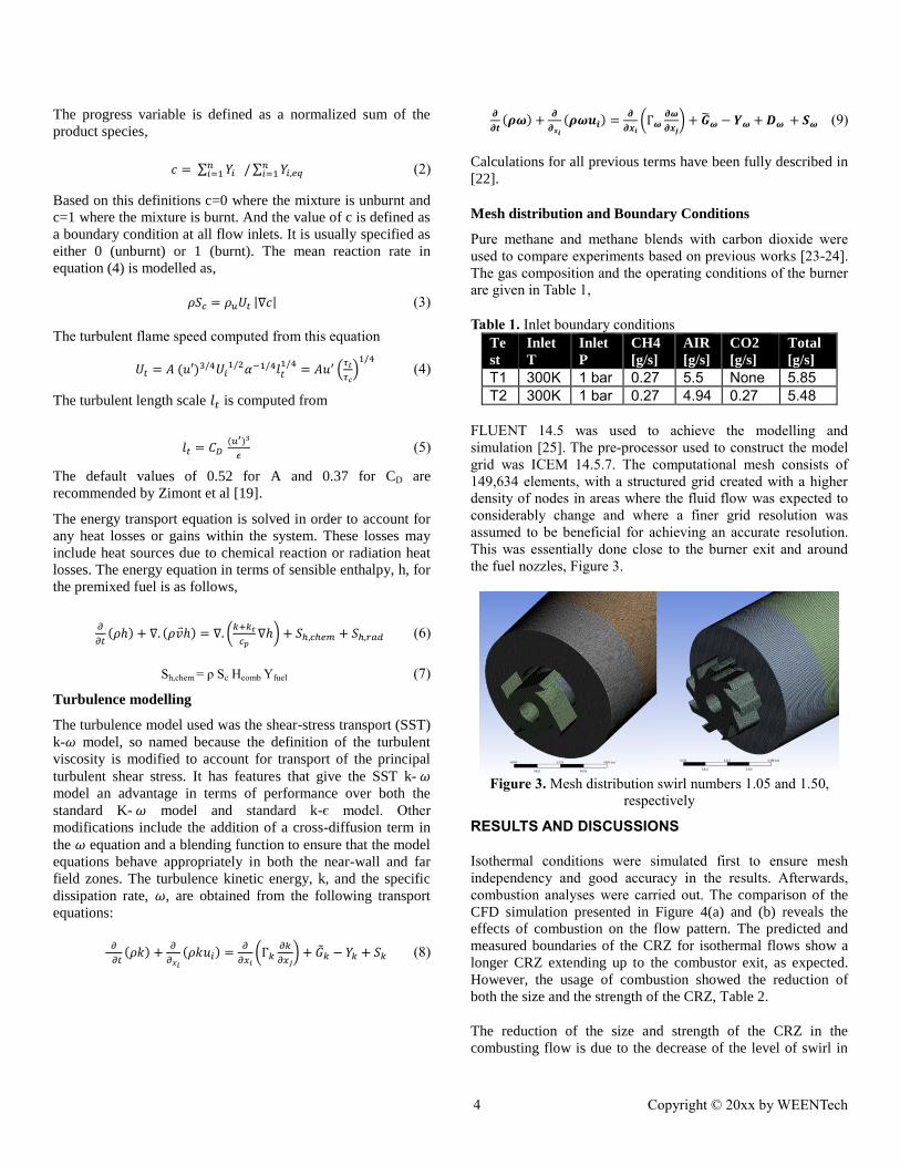
FLUENT 14.5 was used to achieve the modelling and
simulation [25]. The pre-processor used to construct the model
grid was ICEM 14.5.7. The computational mesh consists of
149,634 elements, with a structured grid created with a higher
density of nodes in areas where the fluid flow was expected to
considerably change and where a finer grid resolution was
assumed to be beneficial for achieving an accurate resolution.
This was essentially done close to the burner exit and around
the fuel nozzles, Figure 3.
Figure 3. Mesh distribution swirl numbers 1.05 and 1.50,
respectively
RESULTS AND DISCUSSIONS
Isothermal conditions were simulated first to ensure mesh
independency and good accuracy in the results. Afterwards,
combustion analyses were carried out. The comparison of the
CFD simulation presented in Figure 4(a) and (b) reveals the
effects of combustion on the flow pattern. The predicted and
measured boundaries of the CRZ for isothermal flows show a
longer CRZ extending up to the combustor exit, as expected.
However, the usage of combustion showed the reduction of
both the size and the strength of the CRZ, Table 2.
The reduction of the size and strength of the CRZ in the
combusting flow is due to the decrease of the level of swirl in

5 Copyright © 20xx by WEENTech
the combustor [3]. The measurements show that the axial
velocities in the forward flow region increase significantly due
to combustion-induced flow acceleration while the tangential
velocities are slightly altered. Consequently, the ratio of the
tangential to axial momentum fluxes decreases substantially.
Table 2. Comparison of isothermal and combustion patters of
the CRZ using different nozzle angles. 30⁰ 45⁰ 60⁰ 90⁰ Conditions
Width 1.23D 1.34D 1.66D 1.19D ISOTH
Higher 2.65D 2.97D 3.41D 2.93D ISOTH
Width 1.19D 1.34D 1.58 D 1.15D COMBUS
Higher 2.53D 2.85D 3.29D 2.89D COMBUS
The usage of CO2 also alters the size and inner turbulence of
the structure; in Table 3 and Figures 6-7 it is clear that the
turbulence intensity inside the CRZ with methane blends is
higher than with pure methane. The use of CO2 increases in
almost 7-10% the turbulence of the structure, whilst
augmenting its width and length in ~10% for all cases, Figure
5. The length of the recirculation zone increases due to the
reduced reaction time of the blend and the higher turbulence
inside of the structure.
The flow rate increases with the intensity of the shear layer.
This will converge into a new structure called High Momentum
Flow Region (HMFR), highly correlated to the CRZ [24]. This
will increase the strength of the CRZ but reduce its dimensions,
as observed in table 4. The addition of CO2 affects the velocity
of the flow, thus showing slower profiles than with pure
methane. At the same time, it seems that the dimensions of the
CRZ with CO2 have increased to a width of 1.30D and height
of 3.53D, compared to a width of 1.19D and a height of 2.53D
with pure methane under similar conditions, Figure 5. Figures
6-7 show the progression of the CRZ and its boundaries,
defined as a region of greater turbulence compared to the pure
methane case. It is clear that the CRZ using CO2 has increased
in size.
Table 3 Comparison of turbulent intensity of all cases pure
methane and blend with CO2
Gas
mixture
30⁰ 45⁰ 60⁰ 90⁰ S
CH4 66.6% 67.4% 65.3% 63.5% 1.05
CH4+CO2 73.6% 76.2% 74.5% 69.4% 1.05
CH4 107% 109% 103.4% 95.4% 1.5
CH4+CO2 116% 117% 106.8% 100.2% 1.5
Figure 8 illustrates the axial velocity using different nozzle
angles at a constant mass flow rate. The smallest CRZ width
size was observed using the 90⁰ geometry, as expected. Also
the 30⁰ nozzle produces higher outlet velocities than the 60° and 45° divergent angles due to the sharp sudden expansion.
The 45° nozzle generates axial velocities 50% slower than the
straight 90° geometry, thus allowing a better recuperation of the
CRZ. This causes an increase in size of CRZ, Figure 5.
Figure 4. Comparison of isothermal and combustion different nozzles
S =1.05 case (a) isothermal and (b) combustion
Table 4. Comparison of CRZ size using all nozzles with swirl
numbers of 1.05 and 1.50.
N 30⁰ 45⁰ 60⁰ 90⁰ Gas
mixture
S
W 1.19D 1.34D 1.58D 1.15D CH4 1.05
H 2.53D 2.85D 3.29D 2.89D CH4 1.05
W 1.07D 1.27D 1.03D 0.95D CH4 1.50
H 2.25D 3.01D 2.85D 2.77D CH4 1.50
W 1.30D 1.34D 1.60D 1.23D CH4+CO2 1.05
H 3.53D 2.89D 3.51D 2.79D CH4+CO2 1.05
W 1.07D 1.27D 1.03D 0.95D CH4+CO2 1.50
H 2.53D 3.01D 2.89D 2.77D CH4+CO2 1.50
The high momentum shearing flow region illustrated in Figure
9 with both swirl numbers of 1.05 and 1.50 shows the
divergence of the flow at the outlet of the nozzle. It is clear that
the increase in swirl number will produce higher stretch in the
radial and tangential direction with a faster decay of velocity in
azimuthal direction and wider CRZs.
Another measured structure was the external recirculation zone
(ERZ), Table 5 and Figure 9. As the divergence of HMFR
increases, the size of ERZ increased. The High Momentum
Flow Region seems to get attached and dragged by the ERZ.

6 Copyright © 20xx by WEENTech
Figure 5. Comparison of CRZ size of all nozzles combustion of
methane and methane blend with CO2 .
Table 5. Comparison of corner recirculation zones with both
swirl number.
30⁰ 45⁰ 60⁰ 90⁰ S
WIDTH 0.22D 0.15D 0.13D 0.22D 1.05
HIGHER 0.79D 0.94D 0.71D 0.75D 1.05
WIDTH 0.18D 0.22D 0.28D 0.3D 1.50
HIGHER 0.53D 0.56D 0.79D 0.98D 1.50
Figure 6. Comparison of turbulence intensity of (a) methane and
(b) methane blend with CO2
Figure 7. Comparison of turbulence intensity of (a) methane and
Figure 8. Comparison of the axial velocity of different angles.
Figure 9. Combustion of methane (a) S=1.05 (b) S=1.50.
-4
-2
0
2
4
6
0.14 0.19
Axi
al V
elo
city
[m
/s]
X/D [M]
30 COMBUS
45 COMBUS
60 COMBUS
90 COMBUS

7 Copyright © 20xx by WEENTech
Conclusions
The CFD predictions of swirl burner aerodynamics show how
variable outlet configurations and inert gas compositions
change the CRZ patterns. The addition of CO2 in the blend
with methane can be of great importance to the change of the
CRZ. It is clear that the CRZ is increased with the usage of
CO2 whilst changing outlet nozzles angles. Changing the angle
of the nozzle will control the direction of shear layer. This in
return could be beneficial for new blends and the increase of
the residence time of the products/reactants of these and other
fuel/diluent compositions. The addition of the CO2 produces
longer recirculation zones that collapse suddenly and far away
from the nozzle. The high turbulence of the CRZ using CO2
can also be an important parameter in the addition of other
species that can improve the combustion process whilst
recirculating CO2 for other applications, ie. carbon capture and
storage.
Acknowledgments
The authors gratefully acknowledge the support of the Welsh
Government Low Carbon Research Initiative Programme, the
EPSRC (grant no EP/G060053) and the European Union via
various grants. Mr. Hesham Baej gratefully acknowledges the
support of the Libyan Embassy and the Libyan Cultural and
Education Bureau in London during his research.
REFERENCES
[1]Sadanandan R., Stohr M., Meier W: “Simultaneous OH-
PLIF and PIV measurements in a gas Turbine model
Combustor”,Applied Physics B, vol. 90, 609-618 (2008).
[2]Huang, Y., and Yang, V: "Dynamics and stability of lean-
premixed swirl stabilized combustion," Progress in Energy and
Combustion Science, 35(4), 293-364 (2009).
[3]Syred N,: A review of oscillation mechanisms and the role
of the PVC in swirl combustion systems, Prog Energy Combust
Sci 32 (2), 93-161(2006).
[4] Megan Karalus: An Investigation of Lean Blowout of
Gaseous Fuel Alternatives to Natural Gas, PhD Thesis,
University of Washington,(2013).
[5] Lieuwen T, Yang V: Combustion Instabilities in Gas
Turbine Engines, Prog. In Astronautics Aeronautics, AIAA,
U.S.A., vol. 210, 213-276 (2005).
[6] Tuttle SG, Chaudhuri S, Kotska S, Koop-Vaughan KM,
Jensen TR, Cetegen BM, Renfro MW: Time-resolved blowoff
transition measurements for two-dimensional bluff body-
stabilized flames in vitiated flow. Combust Flame 159, 291-
305(2012).
[7] Lieuwen T: Unsteady Combustor Physics, Cambridge Press,
U.S.A., pp. 430(2012).
[8] Longwell JP, Frost EE, Weiss MA: Flame stability in bluff
body recirculation zones. Indust Eng Chem 8, 1629-1633
(1953).
[9] Shanbhogue SJ, Husain S, Lieuwen T: Lean blowoff of
bluff body stabilized flames: Scaling and dynamics, Prog
Energy Combust Sci, 35, 98-120 (2009).
[10]Driscoll J: Turbulent premixed combustion: flamelet
structure and its effect on turbulent burning velocities, Progress
in Energy and Combustion Science 34 (1), 91-134(2008).
[11] Poinsot T, Veynante D: Theoretical and Numerical
Combustion, R.T. Edwards, U.S.A., pp. 522(2005).
[12]Valera-Medina A, Syred N, Bowen P :Central
Recirculation Zone Analysis using a Confined Swirl Burner for
Terrestrial Energy, J AIAA Propulsion and Power 29 (1), 195-
204 (2013).
[13]Valera-Medina A, Syred N, Griffiths A Visualization of
Coherent Structures in a Swirl Burner under Isothermal
Conditions. Combustion and Flame 159,1723-1734 (2009).
[14] Shelil, N., Bagdanavicius, A., Griffiths, A. J., Roberts, P.,
and Syred, N: "Flashback Analysis for Hydrogen/Methane
Mixtures for Premixed Swirl Combustion," The 16th IFRF
Members' Conference in Boston, IFRF, USA (2009).
[15] Lieuwen, T, McDonell, V, Petersen, E, Santavicca, D:
Fuel flexibility influences on premixed combustor blowout,
flashback, autoignition, and stability. J. Eng. Gas Turbines
Power 130, 011506 (2008).
[16] Raman V Pitsch H: Large-eddy simulation of a bluff-body-
stabilized non-premixed flame using a recursive filter-
refinement procedure. Combustion and Flame 142 (4) 329-
347(2005).
[17]German A E , Mahmud T :Modelling of non-premixed
swirl burner flows using a Reynolds-stress turbulence closure.
Fuel 84 (5) 583-594(2005).
[18] Versteeg HK and Malalasekera W, An Introduction to
Computational Fluid Dynamics – The Finite Volume Method,
Longman Group Ltd (1995).
[19] Date A W: Introduction to Computational Fluid Dynamics,
Cambridge University Press (2005).
[20] Syred, N.J M.Beer: Combustion in swirling flows: A
review combustion and flame 23,143-201(1974)
[21] Zimont, V., Polifke, W., Bettelini, M., and Weisenstein,
W., July, "An Efficient Computational Model for Premixed
Turbulent Combustion at High Reynolds Numbers Based on a
Turbulent Flame Speed Closure," J. of Gas Turbines Power,
120, 526- 532(1998).
[22] ANSYS FLUENT 12.0 Theory Guide 2009 [Online].
Available:at www.scribd.com/doc/191713736/Ansys-Fluent-
12-0-Theory-Guidem
[23] Baej
H., Valera-Medina A., Bowen P.,
Syred N.,
O’Doherty T., Marsh R ., Impacts on Blowoff by a variety of
CRZs using various gases for Gas Turbines
[24] Vigueras-Zuniga MO, Valera-Medina A, Syred N, Bowen
P: High Momentum Flow Region and Central Recirculation
Zone Interaction in Swirling Flows, SOMIM. Approved
[25] Zimont V, Gas Premixed Combustion at High Turbulence.
Turbulent Flame Closure Model Combustion Model. Exp
Thermal Fluid Sci 21:179– 186 (2000).