Embed Size (px)
Citation preview
Integrated Aircraft Design Network translations such as element and attribute editing (add, remove, replace), rearrangement, sorting, perform tests and make decisions [15].
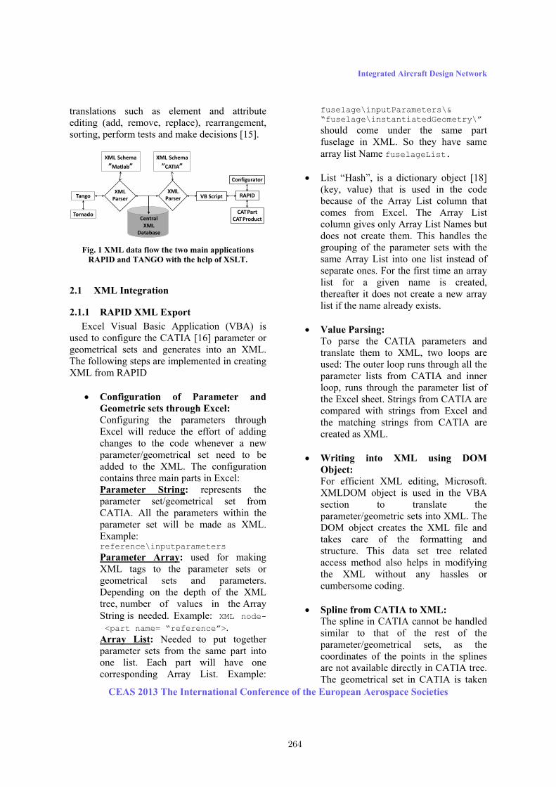
Fig. 1 XML data flow the two main applications RAPID and TANGO with the help of XSLT.
2.1 XML Integration
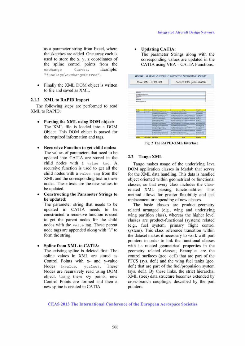
2.1.1 RAPID XML Export Excel Visual Basic Application (VBA) is used to configure the CATIA [16] parameter or geometrical sets and generates into an XML. The following steps are implemented in creating XML from RAPID • Configuration of Parameter and
Geometric sets through Excel: Configuring the parameters through Excel will reduce the effort of adding changes to the code whenever a new parameter/geometrical set need to be added to the XML. The configuration contains three main parts in Excel: Parameter String: represents the parameter set/geometrical set from CATIA. All the parameters within the parameter set will be made as XML. Example: reference\inputparameters Parameter Array: used for making XML tags to the parameter sets or geometrical sets and parameters. Depending on the depth of the XML tree, number of values in the Array String is needed. Example: XML node- <part name= “reference”>. Array List: Needed to put together parameter sets from the same part into one list. Each part will have one corresponding Array List. Example:
fuselage\inputParameters\& “fuselage\instantiatedGeometry\” should come under the same part fuselage in XML. So they have same array list Name fuselageList.
• List “Hash”, is a dictionary object [18] (key, value) that is used in the code because of the Array List column that comes from Excel. The Array List column gives only Array List Names but does not create them. This handles the grouping of the parameter sets with the same Array List into one list instead of separate ones. For the first time an array list for a given name is created, thereafter it does not create a new array list if the name already exists. • Value Parsing: To parse the CATIA parameters and translate them to XML, two loops are used: The outer loop runs through all the parameter lists from CATIA and inner loop, runs through the parameter list of the Excel sheet. Strings from CATIA are compared with strings from Excel and the matching strings from CATIA are created as XML. • Writing into XML using DOM
Object: For efficient XML editing, Microsoft. XMLDOM object is used in the VBA section to translate the parameter/geometric sets into XML. The DOM object creates the XML file and takes care of the formatting and structure. This data set tree related access method also helps in modifying the XML without any hassles or cumbersome coding. • Spline from CATIA to XML: The spline in CATIA cannot be handled similar to that of the rest of the parameter/geometrical sets, as the coordinates of the points in the splines are not available directly in CATIA tree. The geometrical set in CATIA is taken
Tornado
Tango RAPID
CATPartCATProduct
Configurator
CentralXML
Database
XMLParser
XMLParser
XML Schema”Matlab”
XML Schema”CATIA”
VB Script
CEAS 2013 The International Conference of the European Aerospace Societies 264
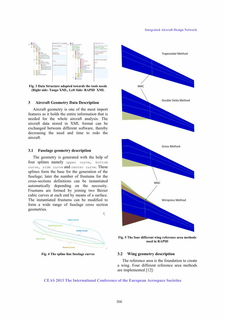
Integrated Aircraft Design Network Fig. 3 Data Structure adapted towards the tools needs
(Right side: Tango XML, Left Side: RAPID XML
3 Aircraft Geometry Data Description Aircraft geometry is one of the most import features as it holds the entire information that is needed for the whole aircraft analysis. The aircraft data stored in XML format can be exchanged between different software, thereby decreasing the need and time to redo the aircraft. 3.1 Fuselage geometry description The geometry is generated with the help of four splines namely upper curve, bottom curve, side curve and center curve. These splines form the base for the generation of the fuselage; later the number of frustums for the cross-sections definitions can be instantiated automatically depending on the necessity. Frustums are formed by joining two Bézier cubic curves at each end by means of a surface. The instantiated frustums can be modified to form a wide range of fuselage cross section geometries.
Fig. 4 The spline line fuselage curves
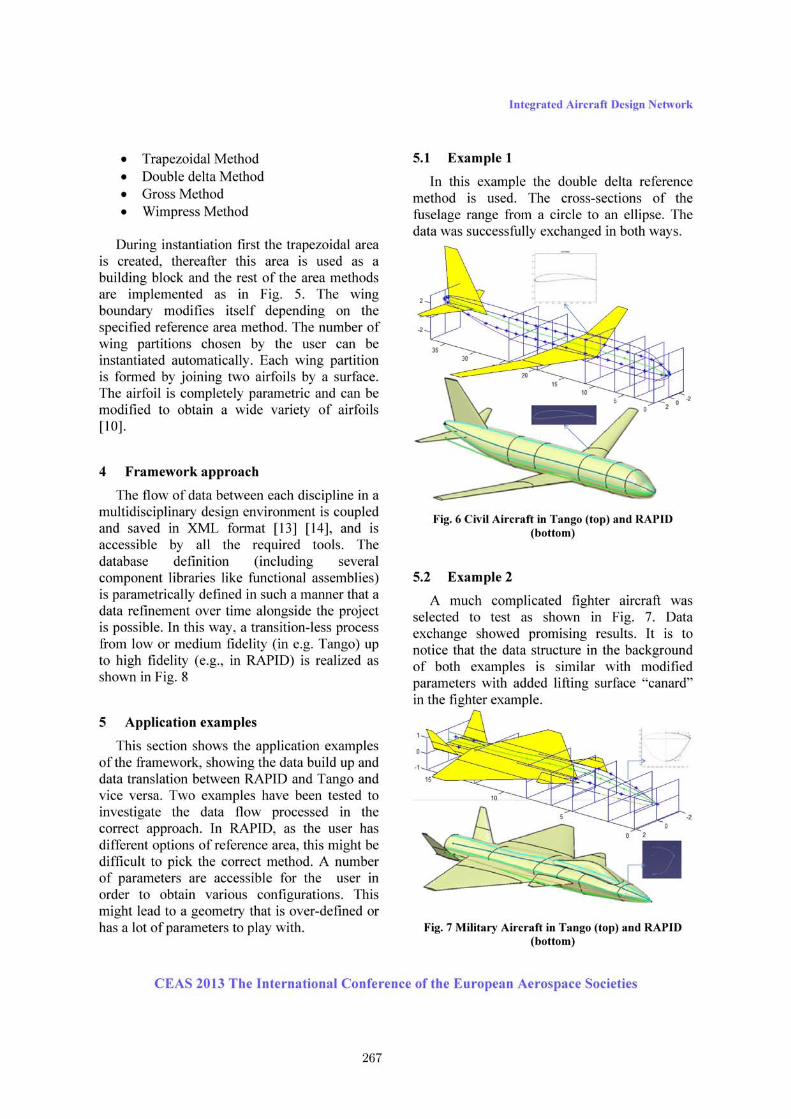
Fig. 5 The four different wing reference area methods
used in RAPID
3.2 Wing geometry description The reference area is the foundation to create a wing. Four different reference area methods are implemented [12]: Upper Curve
Bottom Curve
Side Curve
Center Curve
Combined Curve
Trapezoidal Method
Double Delta Method
Gross Method
Wimpress Method
MAC
MAC
CEAS 2013 The International Conference of the European Aerospace Societies 266
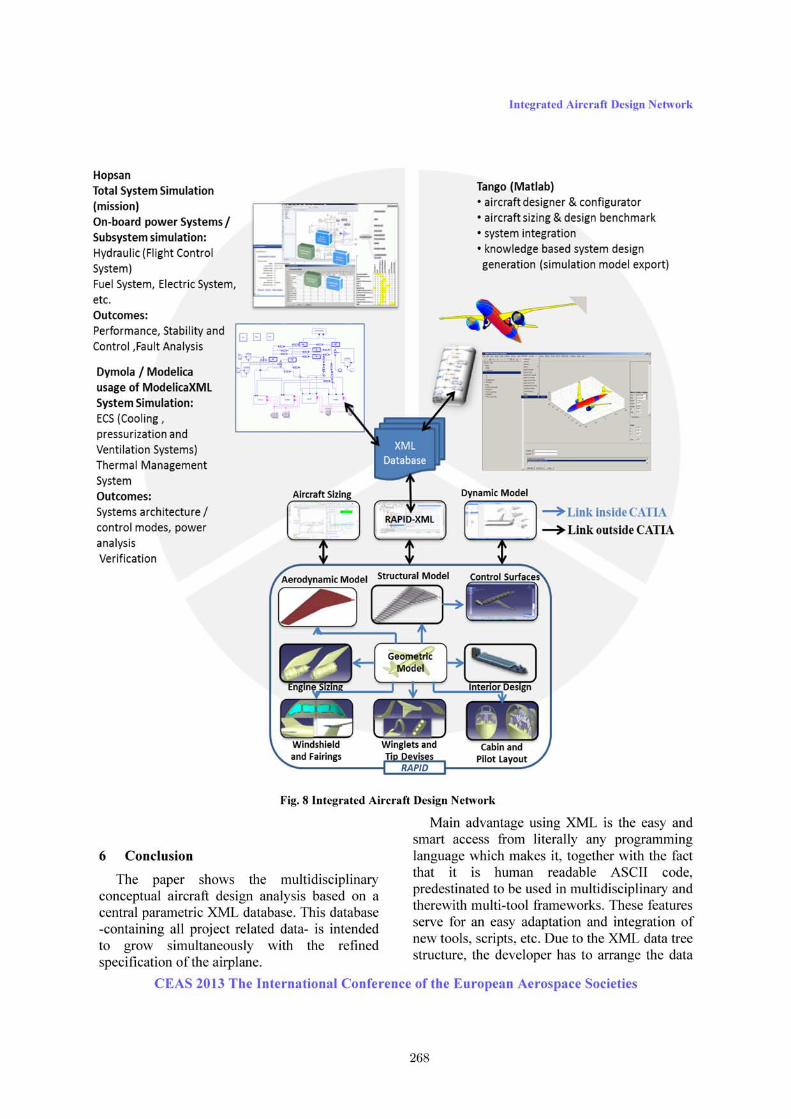
Integrated Aircraft Design Network in a certain position, however the strict tree structure fit not totally towards the needs of a complex product as an aircraft; here, because of the transition of the class alignment from geometrical placement (low level) towards system description (high level), these trees have to be extended by cross-nodes pointers. The 3D CAD description of this data setup is a small fraction of the original data needed in the CATIA environment to establish the geometry; here, extensive usage of knowledge base descriptions, namely knowledge pattern and power copy concepts are used. This method limits the design space in favor of a slim dataset consisting of rather significant parameters. This allows for a direct access of the geometry for other tools, like a geometrical optimization outside the CAD environment. The unified geometry makes meshing easier and serves for no aperture for high fidelity CFD analysis. As proposed in Fig. 6 even simulation models can be generated out of the (mainly geometry) XML aircraft description. Acknowledgement Funding of this work was provided by NFFP, the Swedish National Aviation Engineering Program [11]. The contributing authors wish to thank the NFFP founders for this support. The First author would like to thank Krishnaveni Chitrapu for the helpful suggestion for XML creation from CATIA. References [1] Staack, I., Raghu Chaitanya, M. V., et al., “Parametric Aircraft Conceptual Design Space,”
Proc 28th Congress of the International Council of the Aeronautical Sciences, Brisbane, Australia, 2012. [2] Raymer D. Aircraft design - a conceptual approach, 5th edition, AIAA education series, Washington DC, U.S.A, 2012 [3] Roskam J. Airplane design- part1: Preliminary Sizing of Airplane, DARcoporation, Lawrence, 1985 [4] Torenbeek E. Synthesis of subsonic airplane design, Delft University Press, Delft, Netherlands, 1995 [5] Raymer D. RDS-student: software for aircraft design, sizing, and performance, Volume 10,
AIAA education series, Washington DC, 2006 [6] CEASIOM. Computerized Environment for Aircraft Synthesis and Integrated Optimization Methods software, http://www.ceasiom.com [7] PADLab Software, http://www.luftbau.tu-berlin.de/menue/forschung/padlab [8] Hahn A. Vehicle Sketch Pad: Parametric geometry for conceptual aircraft design, Proc 48th AIAA Aerospace Sciences Meeting, Orlando, Florida, 2010 [9] Ziemer S. A conceptual design tool for multi-disciplinary aircraft design, Proc Aerospace Conference, IEEE, Big Sky, Montana, USA, 2011 [10] Melin. T, Parametric Airfoil Catalog, Part I, Linköping University, ISBN: 978-91-7519-656-5, 2013 [11] VINNOVA. Swedish national aviation engineering research programme, http://www.vinnova.se/en/Our-activities/Cooperation-Programmes/National-Aviation-Engineering-Research-Programme/ [12] Isikveren. A. T., Quasi-Analytical Modeling And Optimization Techniquiques For Transport Aircraft Design, Ph.D. Dissertation, Royal Institute of Technology (KTH), Stockholm, 2002 [13] Risheng Lin and Abdollah A. Afjeh, An XML-Based Integrated Database Model for Multidisciplinary Aircraft Design, Journal of Aerospace Computing, Information, and Communication 2004 1:3, 154-172 [14] Ho-Jun Lee, Jae-Woo Lee, Jeong-Oog Lee, Development of Web services-based Multidisciplinary Design Optimization framework, Advances in Engineering Software, Volume 40, Issue 3, March 2009, Pages 176-183, ISSN 0965-9978, [15] http://www.w3.org/ [16] CATIA V5 Release 21, http://www.3ds.com/ [17] Microsoft Excel, http://www.Microsoft.com/ [18] http://msdn.microsoft.com
CEAS 2013 The International Conference of the European Aerospace Societies 269