Embed Size (px)
Citation preview
An Ankle-Foot Emulation System for the Study of Human Walking Biomechanics
Samuel K. Au Peter Dilworth Hugh Herr
MIT Media Lab Massachusetts Institute of Technology
Cambridge, MA02139, USA Email:[email protected]
MIT Media Lab Massachusetts Institute of Technology
Cambridge, MA02139, USA Email:[email protected]
MIT Media Lab Harvard/MIT Division of Health
Sciences and Technology, Massachusetts Institute of Technology
20 Ames Street, Room E15-419 Cambridge, MA 021314, USA Email: [email protected]
Abstract – Although below-knee prostheses have been commercially available for some time, today’s devices are completely passive, and consequently, their mechanical properties remain fixed with walking speed and terrain. A lack of understanding of the ankle-foot biomechanics and the dynamic interaction between an amputee and a prosthesis is one of the main obstacles in the development of a biomimetic ankle-foot prosthesis. In this paper, we present a novel ankle-foot emulator system for the study of human walking biomechanics. The emulator system is comprised of a high performance, force-controllable, robotic ankle-foot worn by an amputee interfaced to a mobile computing unit secured around his waist. We show that the system is capable of mimicking normal ankle-foot walking behaviour. An initial pilot study supports the hypothesis that the emulator may provide a more natural gait than a conventional passive prosthesis.
Index Terms – Below-knee prosthesis, biomechanics, force control, biomimetic, ankle-foot emulator
I. INTRODUCTION
Although the potential benefit of powered prostheses for both upper and lower extremity amputees has been well documented, most of the research and commercial activity has focused on active upper limb devices [1]-[4]. Today, commercially available ankle-foot prostheses are completely passive, and consequently, their mechanical properties remain fixed with walking speed and terrain [5]. Conversely, normal human ankle stiffness varies within each gait cycle and also with walking speed [6][7]. Furthermore, some studies have indicated that one of the main functions of the human ankle is to provide adequate energy for forward progression of the body [6]-[9]. Not surprisingly, below-knee amputees that use passive ankle-foot prostheses exhibit non-symmetric gait patterns and higher metabolic ambulatory rates [10]-[12]. Thus, in order to mimick the behaviour of the human ankle and to increase gait symmetry and walking economy, a prosthetic ankle-foot device should be able to actively control joint impedance, motive power, and joint position.
In the development of an active ankle-foot prosthesis, the key issue is to have a thorough understanding of ankle-foot walking biomechanics. Previous experimental and theoretical studies on the behaviour of the human ankle have been limited to a qualitative understanding of the functional role of the
human ankle. Although studies have pointed out the impedance characteristics of the human ankle during walking, no one has developed a comprehensive model to describe how the stiffness of the human ankle varies with the walking speed [6]-[8]. Ref. [8] proposed that the human ankle provides energy for forward progression only at fast walking speed. However, other researchers [6][7] have proposed that the human ankle should provide energy during moderate to fast walking speed.
In addition to understanding ankle-foot biomechanics, it is believed that the study of the actual dynamics interaction between the amputee and the prosthesis is essential because: (1) most aforementioned biomechanics studies cover only the normal ankle-foot behaviour, (2) the compliance between the amputee’s stump and the prosthesis socket is difficult to model and greatly complicates the dynamics and (3) human beings are fundamentally adaptive and human behaviour changes with task context and environmental conditions [1][14].
Therefore, it is necessary to develop an ankle-foot emulation system that provides a test bed for testing a broad range of human ankle behaviours and control systems experimentally. We believe that examining a range of characteristics is essential, not only in developing the active below-knee prosthesis, but also in gaining a better understanding the role of human ankle biomechanics and energetics. These findings may further be applied to other research areas such as control theory for biped robotics.
In this paper, we first present the design of a novel ankle-foot emulator based on ankle-foot walking biomechanics. We then discuss the design of the force controller and overall control architecture of the emulator. Finally, we show the results of an initial pilot experiment of the emulator on an amputee.
II. HUMAN ANKLE-FOOT EMULATOR DESIGN SPECIFICATIONS
A. Ankle-foot walking biomechanics Understanding normal walking biomechanics provides the
basis for the design and development of the human ankle-foot emulator. Specifically, the function of the human ankle under sagittal plane rotation is described for level-ground walking. From these biomechanical descriptions, the justifications for
Proceedings of the 2006 IEEE International Conference on Robotics and AutomationOrlando, Florida - May 2006
0-7803-9505-0/06/$20.00 ©2006 IEEE 2939
the design specifications of the ankle-foot emulation system are established.
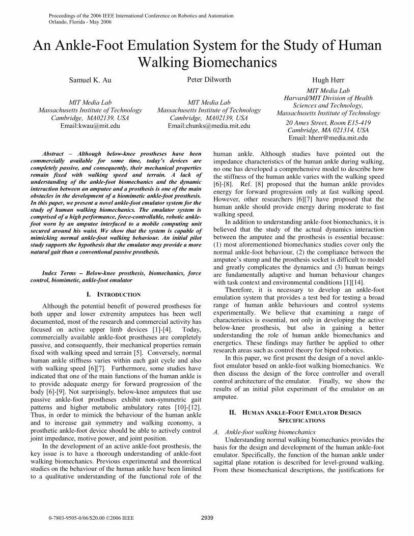
A level-ground walking gait cycle is typically defined as beginning with the heel strike of one foot and ending at the next heel strike of the same foot [13]. The main subdivisions of the gait cycle are the stance phase (~60%) and the swing phase (~40%) (Fig. 1). The swing phase represents the portion of the gait cycle when the foot is off the ground. The stance phase begins at heel-strike when the heel touches the floor and ends at toe-off when the same foot rises from the ground surface. From [6][7], we can further divide the stance phase into three sub-phases: Controlled Plantarflexion (CP), Controlled Dorsiflexion (CD), and Powered Plantarflexion (PP). A summary of descriptions for each phase and the corresponding ankle functions are shown in Fig. 1. Also, a typical ankle torque versus angle plot is shown in Fig. 2.
Controlled Plantarflexion (CP) CP begins at heel-strike and ends at foot-flat. Simply
speaking, CP describes the process by which the heel and forefoot initially makes contact with the ground. In [6][7], researchers showed that ankle joint behaviour during CP was consistent with a linear spring response where joint torque is proportional to joint position. As can be seen in Fig. 2, segment 1-2 illustrates the linear spring behaviour of the ankle.
Controlled Dorsiflexion (CD)CD begins at foot-flat and continues until the ankle
reaches a state of maximum dorsiflexion. Ankle torque versus position during the CD period can often be described as a nonlinear spring where stiffness increases with increasing ankle position. The main function of the human ankle during CD is to store the elastic energy necessary to propel the body upwards and forwards during the PP phase [6][7]. Segment 2-3 in Fig. 2 reveals the nonlinear spring behaviour of the human ankle joint during CD.
Powered Plantarflexion (PP)PP phase begins after CD and ends at the instant of toe-
off. Because the work generated during PP is more than the negative work absorbed during the CP and CD phases for moderate to fast walking speeds [6][7][9], additional energy is supplied along with the spring energy stored during the CD phase to achieve the high plantarflexion power during late stance. Therefore, during PP the ankle can be modelled as a torque source in series with the CD spring. The area enclosed by the points 2, 3, and 4 shows the amount of additional energy added to the ankle joint during PP.
ControlledPlantarflexion
PoweredPlantarflexion
Heel-strike Toe-off
Function:variableLinearSpring
Foot-flat
Function:position
control
ControlledDorsiflexion
Function:torque actuctor + spring
Heel-strike
Function: VariableNonlinearSpring
Stance 60%
Swing Phase
SwingPhase
Max.Dorsiflexion
Fig. 1 Biomechanics of a normal human ankle during level-ground walking.
Fig. 2 Ankle torque versus angle during level-ground walking. The segments 1-2, 2-3, and 3-4 represent the ankle torque-angle behaviours during CP, CD, and PP phases of gait, respectively.
B. Design Specifications Based on the above biomechanical descriptions of the
human ankle, design specifications for the human ankle-foot emulator are as follows:
1. the system must provide a large instantaneous output power and torque, i.e. about 300W and 170Nm for a 75kg person [6];
2. the system must be capable of changing its stiffness within each phase of gait; and
3. the system must be capable of controlling joint position during the swing phase.
Table 1 Human Ankle Specifications Peak Power Peak Torque Peak Angular
velocity Normalized Human Ankle Response
4W/kg 2.3Nm/kg 0.25Nm/kg at 5 rad/sec
Approximate values for a 75kg person
300W 172.5Nm 18.75Nm/kg at 5 rad/sec
2940
III. DESIGN OF THE EMULATION SYSTEM
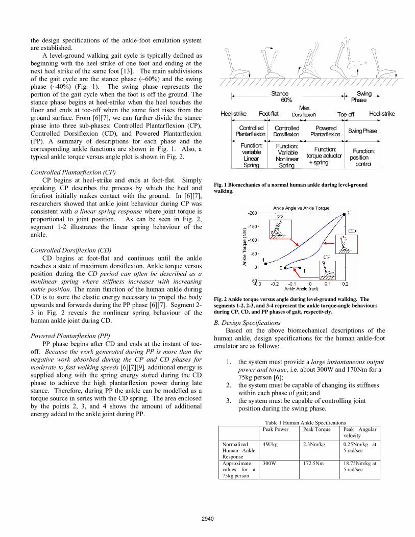
A. Mechanical Design of the Emulator A SolidWorks model and a photograph of the human
ankle-foot emulator prototype are shown in Figs. 3 and 4, respectively. As shown in Fig. 3, there are four main mechanical elements in the system: (a) a high power output motor (Maxon RE-max 40), (b) transmission (gearhead and the bevel gears), (c) series springs, and (d) a carbon compositeleaf spring prosthetic foot. We combine the first three components ((a)-(c)) into a rotary Series-Elastic Actuator (SEA) to mimick the behavior of a human ankle joint, while the elastic leaf spring emulates the function of a human foot.
Fig. 3 Mechanical design of the human ankle-foot emulator.
Fig. 4 Prototype of the human ankle-foot emulator
A Series-Elastic Actuator (SEA), previously developed for legged robots [16][17], consists of a dc motor in series with a spring (or spring structure) via a mechanical transmission. The SEA provides precise force control by controlling the extent to which the series spring is compressed. Using a linear potentiometer, we can obtain the actual force applied to the load by measuring the deflection of the series spring.
The advantages of the SEA are that it has low impedance, the motor is isolated from shock loads, and the effects of backlash, torque ripple, and friction are filtered by the spring [16][17]. As SEAs are force controllable actuators, they are safer to use with human subjects as opposed to direct drive systems that are position controlled. In the control of SEAs, a limiting maximum force can be specified that will not cause harm to the human subject. All these advantages make SEAs a good choose for human rehabilitation and augmentation applications.
Although [18] has proposed different types of cable-driven rotary SEAs, the maximum output power and torque
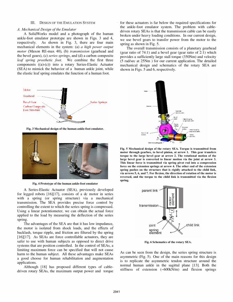
for these actuators is far below the required specifications for the ankle-foot emulator system. The problem with cable-driven rotary SEAs is that the transmission cable can be easily broken under heavy loading conditions. In our current design, we use bevel gears to transfer power from the motor to the spring as shown in Fig. 5.
The overall transmission consists of a planetary gearhead (gear ratio of 74:1) and a bevel gear (gear ratio of 2:1) which provides a sufficiently large stall torque (350Nm) and velocity (5 rad/sec at 25Nm ) for our current application. The detailed mechanical design and schematics of the rotary SEA are shown in Figs. 5 and 6, respectively.
Fig. 5 Mechanical design of the rotary SEA. Torque is transmitted from motor through gearbox, to bevel pinion, at arrow 1. This gear transfers torque to the large bevel gear at arrow 2. The rotational motion of the large bevel gear is converted to linear motion via the joint at arrow 3. This linear force is transmitted via spring pivot rod into a compression force on the extension springs at arrow 4. The other end of the extension spring pushes on the structure that is rigidly attached to the child link, via arrows 5, 6, and 7. For flexion, the direction of rotation of the motor is reversed, and the torque to the child link is transmitted via the flexion spring.
Fig. 6 Schematics of the rotary SEA.
As can be seen from the design, the series spring structure is asymmetric (Fig. 5). One of the main reasons for this design is to replicate the asymmetric tendon structure around the normal human ankle in the sagittal plane [13]. Both the stiffness of extension (~600kN/m) and flexion springs
2941
(~300kN/m) are designed based on the specifications of human ankle data [13].
A carbon composite leaf spring structure is used to provide shock absorption during foot strike, energy storage during the early stance period, and energy return in the late stance period. The specifications of the emulator system are listed in Table 2.
Table 2 A summary of the specifications for the current design
Current Design A 75kg person
Peak Power 440W 240W Peak Torque 340 Nm 172.5Nm
Peak Velocity 25 Nm at 5 rad/sec 19 Nm at 5 rad/sec
Weight 2.5kg N/A Height 0.32m N/A
Max. Allowable Dorsiflexion 25 deg 25 deg Max. Allowable Plantarflexion 45 deg 45 deg
B. Sensors and Computing Platform We installed a 5kOhm linear potentiometer across the
flexion and extension springs to measure the displacement of the springs. We also mounted a 500-line quadrature encoder (US digital, inc.) in between the parent link mounting plate and child link mounting plate to measure the joint angle of the emulator (Fig. 6). Six capacitive force transducers were placed on the bottom of the foot: two sensors beneath the heel and four beneath the forefoot region.
Using cabling, the emulator was connected to a multifunctional I/O board from Sensory Co., Inc (Model 526) that was interfaced with a PC104 Pentium III CPU (MSMP3XEG, from Advanced Digital Logic, Inc). The system runs the Matlab Kernel for xPC target application [19]. The target PC (PC104) can communicate with a host computer via Ethernet. The host computer sends control commands and obtains sensor data from the target PC104. We powered the dc motor with a motor amplifier (Accelnet Panel ACP-090-36, V= 48volts, Ipk = 36A) from Copley Controls Corp.
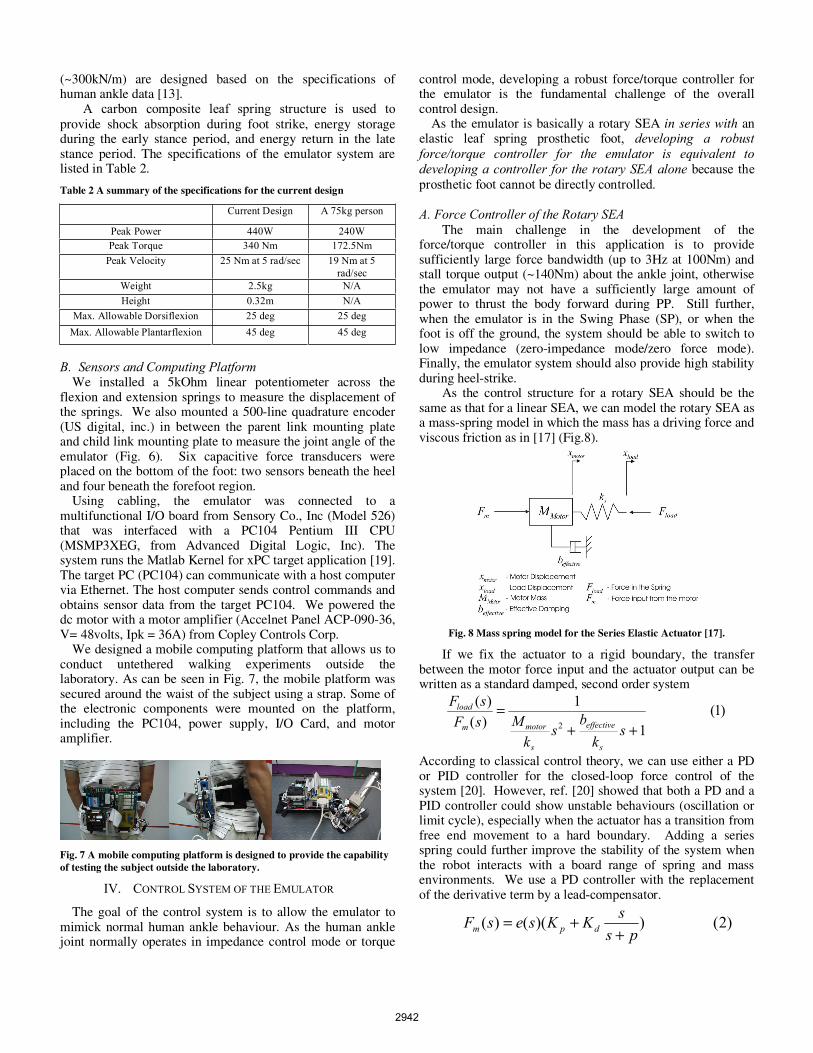
We designed a mobile computing platform that allows us to conduct untethered walking experiments outside the laboratory. As can be seen in Fig. 7, the mobile platform was secured around the waist of the subject using a strap. Some of the electronic components were mounted on the platform, including the PC104, power supply, I/O Card, and motor amplifier.
Fig. 7 A mobile computing platform is designed to provide the capability of testing the subject outside the laboratory.
IV. CONTROL SYSTEM OF THE EMULATOR
The goal of the control system is to allow the emulator to mimick normal human ankle behaviour. As the human ankle joint normally operates in impedance control mode or torque
control mode, developing a robust force/torque controller for the emulator is the fundamental challenge of the overall control design.
As the emulator is basically a rotary SEA in series with an elastic leaf spring prosthetic foot, developing a robust force/torque controller for the emulator is equivalent to developing a controller for the rotary SEA alone because the prosthetic foot cannot be directly controlled.
A. Force Controller of the Rotary SEA The main challenge in the development of the
force/torque controller in this application is to provide sufficiently large force bandwidth (up to 3Hz at 100Nm) and stall torque output (~140Nm) about the ankle joint, otherwise the emulator may not have a sufficiently large amount of power to thrust the body forward during PP. Still further, when the emulator is in the Swing Phase (SP), or when the foot is off the ground, the system should be able to switch to low impedance (zero-impedance mode/zero force mode). Finally, the emulator system should also provide high stability during heel-strike.
As the control structure for a rotary SEA should be the same as that for a linear SEA, we can model the rotary SEA as a mass-spring model in which the mass has a driving force and viscous friction as in [17] (Fig.8).
Fig. 8 Mass spring model for the Series Elastic Actuator [17].
If we fix the actuator to a rigid boundary, the transfer between the motor force input and the actuator output can be written as a standard damped, second order system
)1(1
1)()(
2 ++=
sk
bs
kMsF
sF
s
effective
s
motorm
load
According to classical control theory, we can use either a PD or PID controller for the closed-loop force control of the system [20]. However, ref. [20] showed that both a PD and a PID controller could show unstable behaviours (oscillation or limit cycle), especially when the actuator has a transition from free end movement to a hard boundary. Adding a series spring could further improve the stability of the system when the robot interacts with a board range of spring and mass environments. We use a PD controller with the replacement of the derivative term by a lead-compensator.
)2())(()(ps
sKKsesF dpm ++=
2942
The main function of the lead compensator in (2) is as a differentiator that only differentiates the low frequency components of the signal measured by the potentiometer. The pole of the controller was set to 30Hz, which is sufficiently larger than the normal bandwidth of the human ankle during normal walking (~3Hz).
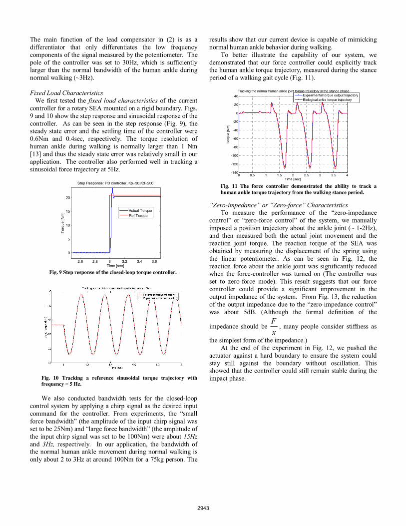
Fixed Load Characteristics We first tested the fixed load characteristics of the current controller for a rotary SEA mounted on a rigid boundary. Figs. 9 and 10 show the step response and sinusoidal response of the controller. As can be seen in the step response (Fig. 9), the steady state error and the settling time of the controller were 0.6Nm and 0.4sec, respectively. The torque resolution of human ankle during walking is normally larger than 1 Nm [13] and thus the steady state error was relatively small in our application. The controller also performed well in tracking a sinusoidal force trajectory at 5Hz.
2.6 2.8 3 3.2 3.4 3.6
0
5
10
15
20
Time [sec]
Tor
que
[Nm
]
Step Response: PD controller, Kp=30,Kd=200
Actual TorqueRef Torque
Fig. 10 Tracking a reference sinusoidal torque trajectory with frequency = 5 Hz.
We also conducted bandwidth tests for the closed-loop control system by applying a chirp signal as the desired input command for the controller. From experiments, the “small force bandwidth” (the amplitude of the input chirp signal was set to be 25Nm) and “large force bandwidth” (the amplitude of the input chirp signal was set to be 100Nm) were about 15Hzand 3Hz, respectively. In our application, the bandwidth of the normal human ankle movement during normal walking is only about 2 to 3Hz at around 100Nm for a 75kg person. The
results show that our current device is capable of mimicking normal human ankle behavior during walking.
To better illustrate the capability of our system, we demonstrated that our force controller could explicitly track the human ankle torque trajectory, measured during the stance period of a walking gait cycle (Fig. 11).
0 0.5 1 1.5 2 2.5 3 3.5 4-140
-120
-100
-80
-60
-40
-20
0
20
40
Time [sec]
To
rque
[Nm
]
Tracking the normal human ankle joint torque trajectory in the stance phaseExperimental torque output trajectoryBiological ankle torque trajectory
Fig. 11 The force controller demonstrated the ability to track a human ankle torque trajectory from the walking stance period.
“Zero-impedance” or “Zero-force” Characteristics To measure the performance of the “zero-impedance control” or “zero-force control” of the system, we manually imposed a position trajectory about the ankle joint (~ 1-2Hz), and then measured both the actual joint movement and the reaction joint torque. The reaction torque of the SEA was obtained by measuring the displacement of the spring using the linear potentiometer. As can be seen in Fig. 12, the reaction force about the ankle joint was significantly reduced when the force-controller was turned on (The controller was set to zero-force mode). This result suggests that our force controller could provide a significant improvement in the output impedance of the system. From Fig. 13, the reduction of the output impedance due to the “zero-impedance control” was about 5dB. (Although the formal definition of the
impedance should be xF
, many people consider stiffness as
the simplest form of the impedance.) At the end of the experiment in Fig. 12, we pushed the
actuator against a hard boundary to ensure the system could stay still against the boundary without oscillation. This showed that the controller could still remain stable during the impact phase.
Fig. 9 Step response of the closed-loop torque controller.
2943
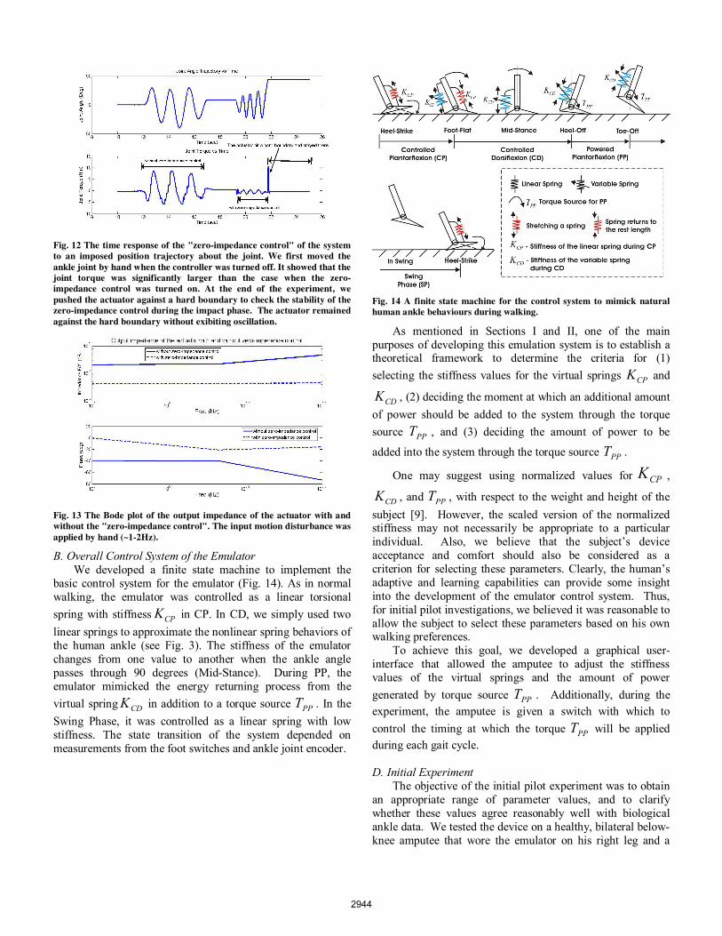
Fig. 12 The time response of the "zero-impedance control" of the system to an imposed position trajectory about the joint. We first moved the ankle joint by hand when the controller was turned off. It showed that the joint torque was significantly larger than the case when the zero-impedance control was turned on. At the end of the experiment, we pushed the actuator against a hard boundary to check the stability of the zero-impedance control during the impact phase. The actuator remained against the hard boundary without exibiting oscillation.
Fig. 13 The Bode plot of the output impedance of the actuator with and without the "zero-impedance control". The input motion disturbance was applied by hand (~1-2Hz).
B. Overall Control System of the Emulator We developed a finite state machine to implement the
basic control system for the emulator (Fig. 14). As in normal walking, the emulator was controlled as a linear torsional spring with stiffness CPK in CP. In CD, we simply used two linear springs to approximate the nonlinear spring behaviors of the human ankle (see Fig. 3). The stiffness of the emulator changes from one value to another when the ankle angle passes through 90 degrees (Mid-Stance). During PP, the emulator mimicked the energy returning process from the virtual spring CDK in addition to a torque source PPT . In the Swing Phase, it was controlled as a linear spring with low stiffness. The state transition of the system depended on measurements from the foot switches and ankle joint encoder.
Fig. 14 A finite state machine for the control system to mimick natural human ankle behaviours during walking.
As mentioned in Sections I and II, one of the main purposes of developing this emulation system is to establish a theoretical framework to determine the criteria for (1) selecting the stiffness values for the virtual springs CPK and
CDK , (2) deciding the moment at which an additional amount of power should be added to the system through the torque source PPT , and (3) deciding the amount of power to be
added into the system through the torque source PPT .
One may suggest using normalized values for CPK ,
CDK , and PPT , with respect to the weight and height of the subject [9]. However, the scaled version of the normalized stiffness may not necessarily be appropriate to a particular individual. Also, we believe that the subject’s device acceptance and comfort should also be considered as a criterion for selecting these parameters. Clearly, the human’s adaptive and learning capabilities can provide some insight into the development of the emulator control system. Thus, for initial pilot investigations, we believed it was reasonable to allow the subject to select these parameters based on his own walking preferences.
To achieve this goal, we developed a graphical user-interface that allowed the amputee to adjust the stiffness values of the virtual springs and the amount of power generated by torque source PPT . Additionally, during the experiment, the amputee is given a switch with which to control the timing at which the torque PPT will be applied during each gait cycle.
D. Initial Experiment The objective of the initial pilot experiment was to obtain
an appropriate range of parameter values, and to clarify whether these values agree reasonably well with biological ankle data. We tested the device on a healthy, bilateral below-knee amputee that wore the emulator on his right leg and a
2944
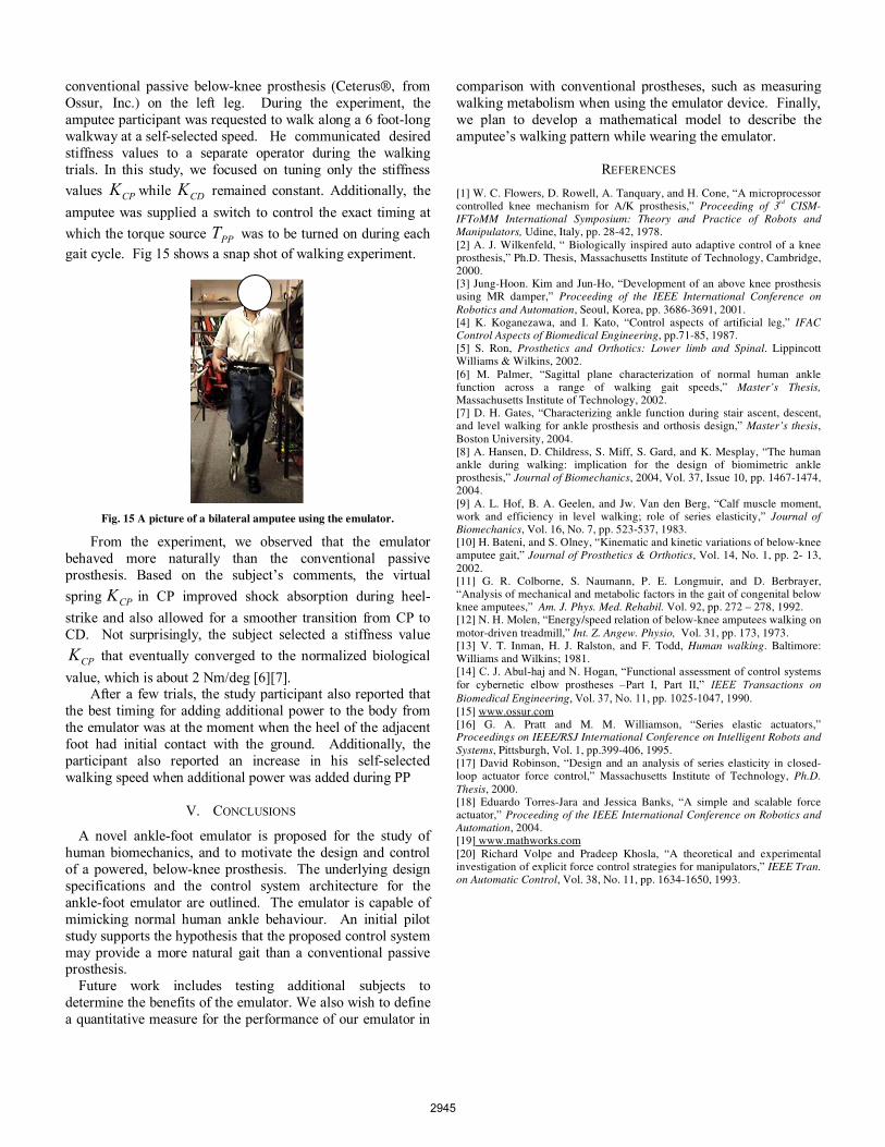
conventional passive below-knee prosthesis (Ceterus®, from Ossur, Inc.) on the left leg. During the experiment, the amputee participant was requested to walk along a 6 foot-long walkway at a self-selected speed. He communicated desired stiffness values to a separate operator during the walking trials. In this study, we focused on tuning only the stiffness values CPK while CDK remained constant. Additionally, the amputee was supplied a switch to control the exact timing at which the torque source PPT was to be turned on during each gait cycle. Fig 15 shows a snap shot of walking experiment.
Fig. 15 A picture of a bilateral amputee using the emulator.
From the experiment, we observed that the emulator behaved more naturally than the conventional passive prosthesis. Based on the subject’s comments, the virtual spring CPK in CP improved shock absorption during heel-strike and also allowed for a smoother transition from CP to CD. Not surprisingly, the subject selected a stiffness value
CPK that eventually converged to the normalized biological value, which is about 2 Nm/deg [6][7].
After a few trials, the study participant also reported that the best timing for adding additional power to the body from the emulator was at the moment when the heel of the adjacent foot had initial contact with the ground. Additionally, the participant also reported an increase in his self-selected walking speed when additional power was added during PP
V. CONCLUSIONS
A novel ankle-foot emulator is proposed for the study of human biomechanics, and to motivate the design and control of a powered, below-knee prosthesis. The underlying design specifications and the control system architecture for the ankle-foot emulator are outlined. The emulator is capable of mimicking normal human ankle behaviour. An initial pilot study supports the hypothesis that the proposed control system may provide a more natural gait than a conventional passive prosthesis.
Future work includes testing additional subjects to determine the benefits of the emulator. We also wish to define a quantitative measure for the performance of our emulator in
comparison with conventional prostheses, such as measuring walking metabolism when using the emulator device. Finally, we plan to develop a mathematical model to describe the amputee’s walking pattern while wearing the emulator.
REFERENCES
[1] W. C. Flowers, D. Rowell, A. Tanquary, and H. Cone, “A microprocessor controlled knee mechanism for A/K prosthesis,” Proceeding of 3rd CISM-IFToMM International Symposium: Theory and Practice of Robots and Manipulators, Udine, Italy, pp. 28-42, 1978. [2] A. J. Wilkenfeld, “ Biologically inspired auto adaptive control of a knee prosthesis,” Ph.D. Thesis, Massachusetts Institute of Technology, Cambridge, 2000. [3] Jung-Hoon. Kim and Jun-Ho, “Development of an above knee prosthesis using MR damper,” Proceeding of the IEEE International Conference on Robotics and Automation, Seoul, Korea, pp. 3686-3691, 2001. [4] K. Koganezawa, and I. Kato, “Control aspects of artificial leg,” IFAC Control Aspects of Biomedical Engineering, pp.71-85, 1987. [5] S. Ron, Prosthetics and Orthotics: Lower limb and Spinal. Lippincott Williams & Wilkins, 2002. [6] M. Palmer, “Sagittal plane characterization of normal human ankle function across a range of walking gait speeds,” Master’s Thesis, Massachusetts Institute of Technology, 2002. [7] D. H. Gates, “Characterizing ankle function during stair ascent, descent, and level walking for ankle prosthesis and orthosis design,” Master’s thesis,Boston University, 2004. [8] A. Hansen, D. Childress, S. Miff, S. Gard, and K. Mesplay, “The human ankle during walking: implication for the design of biomimetric ankle prosthesis,” Journal of Biomechanics, 2004, Vol. 37, Issue 10, pp. 1467-1474, 2004. [9] A. L. Hof, B. A. Geelen, and Jw. Van den Berg, “Calf muscle moment, work and efficiency in level walking; role of series elasticity,” Journal of Biomechanics, Vol. 16, No. 7, pp. 523-537, 1983. [10] H. Bateni, and S. Olney, “Kinematic and kinetic variations of below-knee amputee gait,” Journal of Prosthetics & Orthotics, Vol. 14, No. 1, pp. 2- 13, 2002. [11] G. R. Colborne, S. Naumann, P. E. Longmuir, and D. Berbrayer, “Analysis of mechanical and metabolic factors in the gait of congenital below knee amputees,” Am. J. Phys. Med. Rehabil. Vol. 92, pp. 272 – 278, 1992. [12] N. H. Molen, “Energy/speed relation of below-knee amputees walking on motor-driven treadmill,” Int. Z. Angew. Physio, Vol. 31, pp. 173, 1973. [13] V. T. Inman, H. J. Ralston, and F. Todd, Human walking. Baltimore: Williams and Wilkins; 1981. [14] C. J. Abul-haj and N. Hogan, “Functional assessment of control systems for cybernetic elbow prostheses –Part I, Part II,” IEEE Transactions on Biomedical Engineering, Vol. 37, No. 11, pp. 1025-1047, 1990.[15] www.ossur.com[16] G. A. Pratt and M. M. Williamson, “Series elastic actuators,” Proceedings on IEEE/RSJ International Conference on Intelligent Robots and Systems, Pittsburgh, Vol. 1, pp.399-406, 1995. [17] David Robinson, “Design and an analysis of series elasticity in closed-loop actuator force control,” Massachusetts Institute of Technology, Ph.D. Thesis, 2000. [18] Eduardo Torres-Jara and Jessica Banks, “A simple and scalable force actuator,” Proceeding of the IEEE International Conference on Robotics and Automation, 2004. [19] www.mathworks.com[20] Richard Volpe and Pradeep Khosla, “A theoretical and experimental investigation of explicit force control strategies for manipulators,” IEEE Tran. on Automatic Control, Vol. 38, No. 11, pp. 1634-1650, 1993.
2945