Embed Size (px)
Citation preview
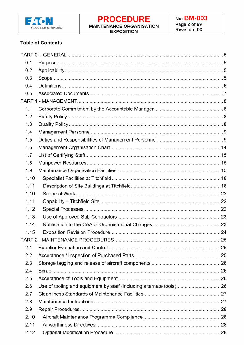
PROCEDURE MAINTENANCE ORGANISATION
EXPOSITION
No: BM-003 Page 2 of 69 Revision: 03
Table of Contents PART 0 – GENERAL ................................................................................................................. 5
0.1 Purpose: ....................................................................................................................... 5
0.2 Applicability ................................................................................................................... 5
0.3 Scope: ........................................................................................................................... 5
0.4 Definitions ..................................................................................................................... 6
0.5 Associated Documents ................................................................................................. 7
PART 1 - MANAGEMENT.......................................................................................................... 8
1.1 Corporate Commitment by the Accountable Manager .................................................. 8
1.2 Safety Policy ................................................................................................................. 8
1.3 Quality Policy ................................................................................................................ 8
1.4 Management Personnel ................................................................................................ 9
1.5 Duties and Responsibilities of Management Personnel ................................................ 9
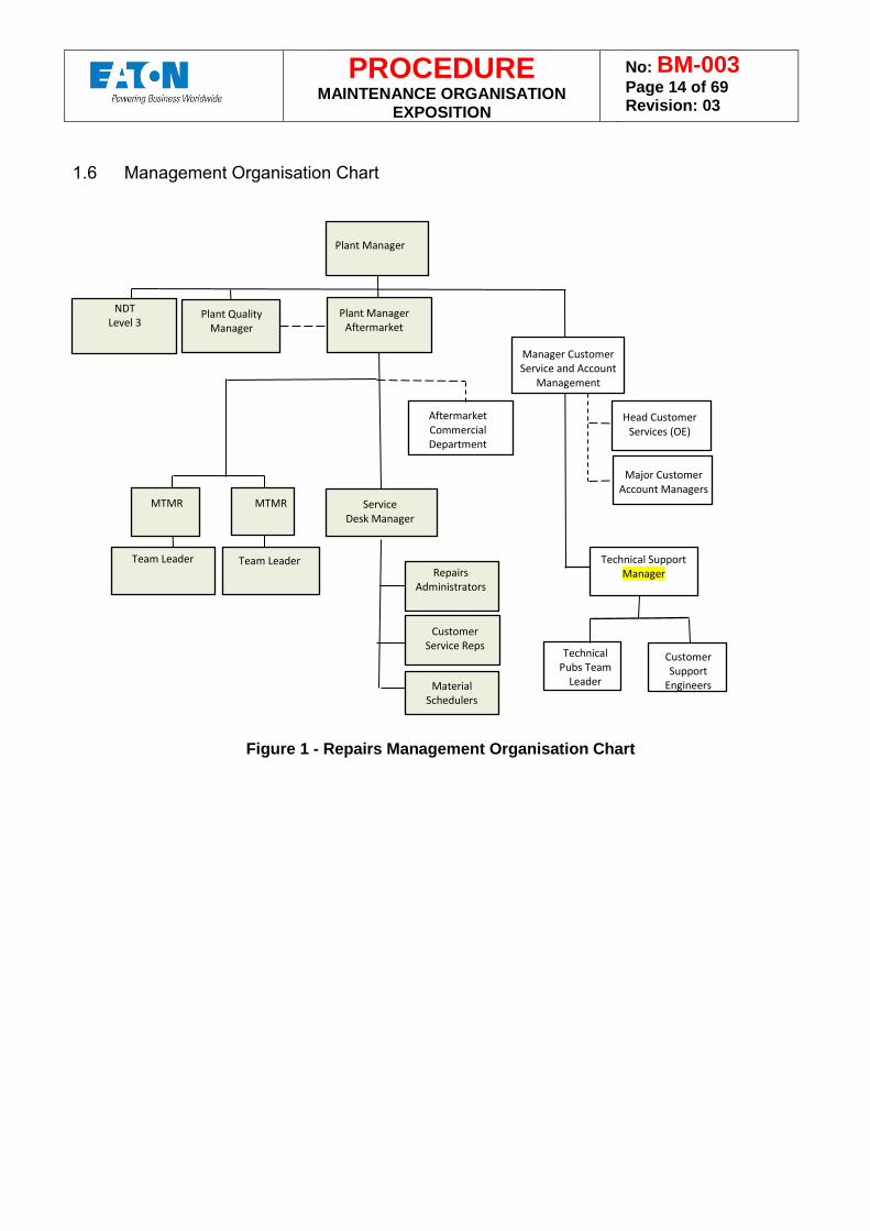
1.6 Management Organisation Chart ................................................................................ 14
1.7 List of Certifying Staff .................................................................................................. 15
1.8 Manpower Resources ................................................................................................. 15
1.9 Maintenance Organisation Facilities ........................................................................... 15
1.10 Specialist Facilities at Titchfield ............................................................................... 18
1.11 Description of Site Buildings at Titchfield ................................................................. 18
1.10 Scope of Work ......................................................................................................... 22
1.11 Capability – Titchfield Site ....................................................................................... 22
1.12 Special Processes ................................................................................................... 22
1.13 Use of Approved Sub-Contractors ........................................................................... 23
1.14 Notification to the CAA of Organisational Changes ................................................. 23
1.15 Exposition Revision Procedure ................................................................................ 24
PART 2 - MAINTENANCE PROCEDURES ............................................................................. 25
2.1 Supplier Evaluation and Control ................................................................................. 25
2.2 Acceptance / Inspection of Purchased Parts .............................................................. 25
2.3 Storage tagging and release of aircraft components .................................................. 26
2.4 Scrap .......................................................................................................................... 26
2.5 Acceptance of Tools and Equipment .......................................................................... 26
2.6 Use of tooling and equipment by staff (including alternate tools) ................................ 26
2.7 Cleanliness Standards of Maintenance Facilities ........................................................ 27
2.8 Maintenance Instructions ............................................................................................ 27
2.9 Repair Procedures ...................................................................................................... 28
2.10 Aircraft Maintenance Programme Compliance ........................................................ 28
2.11 Airworthiness Directives .......................................................................................... 28
2.12 Optional Modification Procedure .............................................................................. 28
PROCEDURE MAINTENANCE ORGANISATION
EXPOSITION
No: BM-003 Page 3 of 69 Revision: 03
2.13 Maintenance Documentation ................................................................................... 29
2.14 Storage of Maintenance Records ............................................................................ 29
2.15 Technical Record Control ........................................................................................ 29
2.15 Rectification of Defects arising during base maintenance ....................................... 30
2.16 Release to Service Procedures ............................................................................... 30
2.17 Records for the Operator ......................................................................................... 30
2.18 Reporting Defects to the Competent Authority / Operators / Manufacturer ............. 30
2.19 Return of Defective Aircraft Components to Store ................................................... 30
2.20 Defective Components to Outside Contractor ......................................................... 30
2.21 Control of the Computer Maintenance Record System ........................................... 31
2.22 Control of Man-Hour Planning versus Scheduled Maintenance Work ..................... 31
2.23 Control of Critical Tasks........................................................................................... 31
2.24 Reference to Specific Maintenance Procedures ...................................................... 31
2.25 Procedures to Detect and Rectify Maintenance Errors ............................................ 31
2.26 Shift / Task Handover Procedures ........................................................................... 32
2.27 Procedure for Notification of Maintenance Data Inaccuracies and Ambiguities to the Type Certificate Holder. ........................................................................................................ 32
PART L2 – ADDITIONAL LINE MAINTENANCE PROCEDURES ........................................... 33
L2.1 Line Maintenance Control of Aircraft Components, Tools, Equipment etc. .............. 33
L2.2 Line Maintenance Procedures related to deviation / Fuelling / De-Icing etc. ........... 33
L2.3 Line Maintenance Control of Faults and Repetitive Faults ...................................... 33
PART 3 – QUALITY SYSTEM PROCEDURES ....................................................................... 35
3.1 Quality Audit of Maintenance Organisation ................................................................. 35
3.2 Management Review .................................................................................................. 35
3.3 Quality Audit of Aircraft ............................................................................................... 35
3.4 Quality Audit Remedial Action Procedure ................................................................... 35
3.5 Certifying Staff Qualification and Training ................................................................... 36
3.6 CERTIFYING STAFF RECORDS ............................................................................... 36
3.7 Quality Audit Personnel .............................................................................................. 37
3.8 Qualifying Inspectors .................................................................................................. 37
3.9 Qualifying Technicians ................................................................................................ 37
3.10 Exemption Process Control ..................................................................................... 38
3.11 Concession Control ................................................................................................. 38
3.12 Qualification Procedure for Specialist Activities ....................................................... 38
3.13 Control of Manufacturers Working Parties ............................................................... 38
3.14 Human Factors Training Programme ...................................................................... 39
3.15 EASA Fuel Systems Regulations (CDCCL/SFAR88/FAR 25/981) .......................... 39
3.16 Extension of Quality System to Subcontractors ....................................................... 40
PART 4 - IR OPS Operators .................................................................................................... 42
PROCEDURE MAINTENANCE ORGANISATION
EXPOSITION
No: BM-003 Page 4 of 69 Revision: 03
PART 5 - APPENDICES .......................................................................................................... 43
Appendix 1 – Level 1 Investigation Report ........................................................................... 44
Appendix 2 - FRACA Sample Page 1 of 2 ............................................................................ 46
Appendix 3 CAA Occurrence Report (CA1673) ................................................................ 48
Appendix 4 – Scrap Certificate ............................................................................................. 50
Appendix 5 – Picking List ..................................................................................................... 51
Appendix 6 – Build Sheet ..................................................................................................... 52
Appendix 7 – Test Reject & Rectification Card ..................................................................... 53
Appendix 8 – Test Certificate ............................................................................................... 54
Appendix 9 – EASA Form 1.................................................................................................. 55
Appendix 10 – EASA Form 1 Dual (EASA/FAA) Release Certificate ................................... 56
Appendix 11 – EASA Form 1 Dual (EASA/TCCA) Release Certificate ................................ 57
Appendix 12 – EASA Form 1 Triple (EASA/FAA/TCCA) Release Certificate ....................... 58
Appendix 13 – EASA Form 1 as FAA 8130-3 ....................................................................... 59
Appendix 14 – Certificate of Conformity (C of C) .................................................................. 60
Appendix 15 – Certifying Staff Authorisation ........................................................................ 61
Appendix 16 – Un-Serviceable Component Tag .................................................................. 62
Appendix 17 – Inspection Repair Report (Example) ............................................................. 63
Appendix 18 – Inspection Repair Report (Example) (Contd...) ............................................. 64
Appendix 19 – Router (Example) ......................................................................................... 65
Appendix 20 – Preliminary Survey Report ............................................................................ 66
Appendix 21 – Employment Summary Form ........................................................................ 67
Appendix 22 – Shelf Life Control Form ................................................................................. 68
PART 6 – Operators Maintenance Procedures ........................................................................ 69
PART 7 – FAA MAG SUPPLEMENT ....................................................................................... 69
PART 8 – TCCA MAG SUPPLEMENT .................................................................................... 69
PROCEDURE MAINTENANCE ORGANISATION
EXPOSITION
No: BM-003 Page 5 of 69 Revision: 03
PART 0 – GENERAL 0.1 Purpose: This document defines the organisation, responsibilities and resources of the Eaton Limited Maintenance Organisation (MO) and identifies how the Company addresses the requirements of IR Part 145. This document is to be used in conjunction with BM-006 (Management Personnel). 0.2 Applicability This exposition is applicable to the elements of the MO which operates at the following address: Abbey Park Southampton Road Titchfield Fareham Hampshire PO14 4QA
Tel: 01329 853000 FAX: 01329 853797
EASA Part 145 Approval Certificate – UK.145.01326 Eaton Limited may use the OEM testing facilities at Titchfield. The company's overall Business System is described in BM-001 0.3 Scope: Eaton Limited is wholly owned by Eaton Corporation and pr ovides a wide range of aerospace accessories for the aviation industry. E aton is a multi-national company. T he company of Eaton Limited is engaged in the design, development, manufacture, test, repair and overhaul of systems and accessories in conformance with regulatory and customer requirements and its own documented standards and specifications. The overall Eaton Limited company operates from facilities located at Titchfield in Hampshire, and South Molton in North Devon and employs some 1300 members of staff. In contrast, the Eaton Limited MO, and hence the scope of this exposition, only comprises the facilities based at Titchfield in Hampshire. This aspect of the MO is co-located with its manufacturing counterpart and employs around 150 staff of which approximately 88 are direct (undertaking repairs) and 60 indirect (support and administrative) The scope of work for the Eaton Limited MO covers the repair and maintenance of components either manufactured directly by the production aspect of the company or another manufacturer as detailed in Section 1.10. The MO is managed by a management team, as shown in Figure 1, and forms one part of the overall company organisation, including one of Design and Production organisation. The MO is supported by other aspects of the company, these include; manufacturing e.g. Goods in, despatch, detail manufacture, treatments and protective finishing, NDT, purchasing, inspection of support activities; and the Quality function for the independent checking of the systems. Final verification of repaired components is carried out by nominated certifying staff. The administration of repair work is carried out by the Repair Administrators who provide the necessary inputs for repairs to be scheduled by the company's manufacturing systems. Repair Technicians then carry out the scheduled work in accordance with the procedures and instructions as described by this
PROCEDURE MAINTENANCE ORGANISATION
EXPOSITION
No: BM-003 Page 6 of 69 Revision: 03
Exposition. Repair Team Leaders report to the MTMRs for all activities associated with the repair process. Section 1.4 of this Exposition and BM-006 describes the specific responsibilities of personnel associated with the Maintenance Organisation. 0.4 Definitions AD Airworthiness Directive AMO Approved Maintenance Organisation CAA Civil Aviation Authority CCP Company Control Procedure CDCCL Critical Design Configuration Control Limitations CMM Component Maintenance Manual C of A Certificate of Airworthiness C of C Certificate of Conformity DIP Document Image Processing EASA European Aviation Safety Agency FAA Federal Aviation Authority FRACA Failure Reporting And Corrective Action ICAO International Civil Aviation Organization IR Implementing Rules MAG Maintenance Annex Guidance MOE Maintenance Organisation Exposition MOR Mandatory Occurrence Reporting MTMR Manufacturing Team Manager Repairs NAA National Aviation Authority OEM Original Equipment Manufacturer PMA Part Manufacturing Approval QA Quality Assurance QMS Quality Management System RSR Repair Service Record SFAR Special Federal Aviation Regulation SB Service Bulletin TC Type Certificate TCCA Transport Canada Civil Aviation TCH Type Certificate Holder UBR Unique Batch Reference
PROCEDURE MAINTENANCE ORGANISATION
EXPOSITION
No: BM-003 Page 7 of 69 Revision: 03
0.5 Associated Documents BM-001 Business Manual BM-004 Capability List BM-006 Management Personnel BM-008 Repairs Training Manual BM-WI-003-1 TCCA Supplement (MAG) BM-WI-003-2 FAA Supplement (MAG) CAP382 Mandatory Occurrence Reporting Scheme CS-109 Technical Publications CS-121 Monitoring of Company Products in Service CS-168 In-service product investigation & reporting CS-170 Organisation and Supervision of Eaton Working Parties CS-171 Customer Support Repairs Process EN-112 Documentation Control GM-101 Goods Received Inspection (GRI) GM-135 GRI Acceptance Sampling and Vendor Rating GM-146 Tooling Design and Manufacture GM-261 Procedure for Controlling Shelf Life Items IR Part 145 Maintenance Organisation Approvals QA-109 Assessment and Control of Suppliers QA-126 Control of Records QA-144 Calibration QA-163 Non-conformance Control QA-185 The Control of Authorised Stamps QA-186 Approved Operator Process QA-222 Certifying Staff Training for Release to Service QA-P-004 Internal Audits of the Quality System QA-P-010 Quality Alert Process QIS 1 Quality Control Requirements For Suppliers TP-100 Training and Certification Requirements for NDT Personnel TS-198 Welding and Brazing Operator Approval WI-QA-163-3 Concession and Production Permit Application Process
PROCEDURE MAINTENANCE ORGANISATION
EXPOSITION
No: BM-003 Page 8 of 69 Revision: 03
PART 1 - MANAGEMENT 1.1 Corporate Commitment by the Accountable Manager This Exposition defines the MO facilities and procedures and identifies how Eaton Limited addresses the requirements of the European Aviation Safety Agency (EASA) Part 145. These procedures are approved by the undersigned and must be adhered to, as applicable, when work/orders are being progressed under the terms of the approval. It is accepted that the Company Procedures do not override the necessity of complying with the applicable Air Navigation Order, EU Legislation or with the Implementing Rules, Airworthiness Notices/Directives or other formal requirements as published by the EASA. 1.2 Safety Policy
• To set our safety standards to the level required by the National Authority, EASA and to incorporate any additional requirements that exceed these standards when required by our customers.
• To identify management responsibilities for safety standards and ensure adherence through formal leadership review.
• To ensure all staff are aware of the safety standards and have a clear understanding of their accountability.
• To provide staff with appropriate tools, procedures and time to carry out tasks in accordance with those procedures.
• To make effective use of our resources. • To establish and promote a c ulture to encourage staff to report safety concerns and
seek to ensure that safety standards are not eroded by commercial factors. • To identify and address potential risks arising from changes in operations, systems,
procedures and staff associated with safety significant functions adhere to our set safety standards.
1.3 Quality Policy
• It is the policy of the company to provide products and services that meet or exceed customer expectations and satisfy them by anticipating their needs and requirements.
• We set and review objectives and continually improve the effectiveness of the Quality Management System.
Signed Ben Bryson Plant Manager (Accountable Manager)
PROCEDURE MAINTENANCE ORGANISATION
EXPOSITION
No: BM-003 Page 9 of 69 Revision: 03
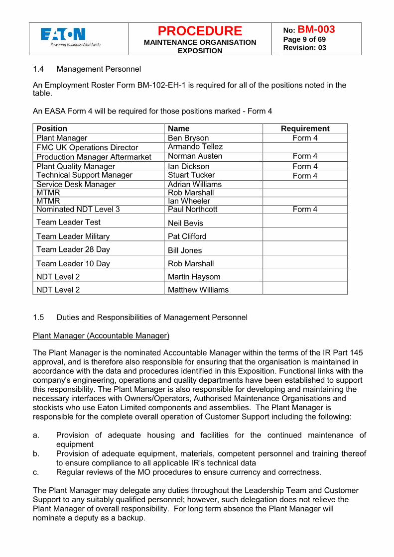
1.4 Management Personnel An Employment Roster Form BM-102-EH-1 is required for all of the positions noted in the table. An EASA Form 4 will be required for those positions marked - Form 4 Position Name Requirement Plant Manager Ben Bryson Form 4 FMC UK Operations Director Armando Tellez Production Manager Aftermarket Norman Austen Form 4 Plant Quality Manager Ian Dickson Form 4 Technical Support Manager Stuart Tucker Form 4 Service Desk Manager Adrian Williams MTMR Rob Marshall MTMR Ian Wheeler Nominated NDT Level 3 Paul Northcott Form 4 Team Leader Test Neil Bevis
Team Leader Military Pat Clifford Team Leader 28 Day Bill Jones
Team Leader 10 Day Rob Marshall NDT Level 2 Martin Haysom NDT Level 2 Matthew Williams
1.5 Duties and Responsibilities of Management Personnel Plant Manager (Accountable Manager)
The Plant Manager is the nominated Accountable Manager within the terms of the IR Part 145 approval, and is therefore also responsible for ensuring that the organisation is maintained in accordance with the data and procedures identified in this Exposition. Functional links with the company's engineering, operations and quality departments have been established to support this responsibility. The Plant Manager is also responsible for developing and maintaining the necessary interfaces with Owners/Operators, Authorised Maintenance Organisations and stockists who use Eaton Limited components and assemblies. The Plant Manager is responsible for the complete overall operation of Customer Support including the following: a. Provision of adequate housing and facilities for the continued maintenance of
equipment b. Provision of adequate equipment, materials, competent personnel and training thereof
to ensure compliance to all applicable IR’s technical data c. Regular reviews of the MO procedures to ensure currency and correctness. The Plant Manager may delegate any duties throughout the Leadership Team and Customer Support to any suitably qualified personnel; however, such delegation does not relieve the Plant Manager of overall responsibility. For long term absence the Plant Manager will nominate a deputy as a backup.
PROCEDURE MAINTENANCE ORGANISATION
EXPOSITION
No: BM-003 Page 10 of 69 Revision: 03
Production Manager Aftermarket (Nominated Person) The Production Manager Aftermarket is responsible for ensuring that maintenance procedures are established and published within the organisation in order to achieve good maintenance practices and compliance with EASA requirements. The Production Manager Aftermarket is directly responsible for ensuring:
a. Ensuring that the company maintains the capability for all the components detailed in the
Capability List. b. Identifying to the Quality Manager any required changes to the Capability List c. Initial verification of the company’s capability to Repair/Overhaul a c omponent prior to
submission for additional capability. d. Manage service performance of repair teams to achieve target arrears reduction and due
date adherence to contractual commitment. e. Manage sales adherence to budget within cells and identify operational opportunities and
risks to sales plans. f. Manage overhead spend to budget and to actual sales in order to maximise margin. g. Promote and develop lean improvement programmes adopting value stream analysis
techniques. h. Continually develop the skills of operational employees to ensure succession and
flexibility thus enabling annual reductions to repair turn-around times. i. Ensure that through effective management of integrated support teams, output planning
and master production scheduling activities are robust. j. Ensure that all team targets are visible and understood. k. Procedures and practices are adhered to when carrying out maintenance. l. All maintenance is correctly certified. m. Records of maintenance carried out are retained safely and s ecurely for the statutory
period. n. The competence of all personnel engaged in maintenance by establishing both training
and continuation training programmes. o. Any corrective action resulting from the quality compliance monitoring activities. p. The shelf life of equipment, scrap, tool calibration and t echnical data are to the latest
revision, issue or controls. The Production Manager Aftermarket may delegate any duties assigned to any suitably qualified personnel within Customer Support. However, such delegation does not relieve the Production Manager Aftermarket of overall responsibility. For long term absence the Production Manager Aftermarket will nominate operations manager as the deputy. Plant Quality Manager The Plant Quality Manager is responsible to the FMC UK Operations Director and Accountable Manager for all Quality Control and Quality Engineering operations, together with the procedural and administrative control of the MO Approval. Accordingly, they are responsible for carrying out a programme of independent audits in order to monitor the maintenance organisation’s compliance with the requirements of the regulations as promulgated in this Exposition and the documented inspection procedures established to control the work undertaken generally within the maintenance organisation. Specific duties include: a. ensuring that all certifying staff have been adequately trained and are authorised to sign
Certificates of Release to Service. A copy of the relevant records will be retained by the Quality Department.
b. maintaining and keeping current, a file of pertinent aviation requirements, specifications, type certification data sheets and airworthiness notices/directives.
c. having the final authority for the release to service of maintained aircraft parts.
PROCEDURE MAINTENANCE ORGANISATION
EXPOSITION
No: BM-003 Page 11 of 69 Revision: 03
d. assessing sub-contractors and external specialist services that are used by the
company in the performance of maintenance. e. assessing suppliers of material and components for satisfactory product quality in
relation to the maintenance organisation. f. responsibility for the co-ordination of matters directly involving the aviation authorities. g. defect analysis so that any adverse trends are identified and responded to promptly.
The duties of the Plant Quality Manager may be delegated as necessary. However such delegation does not relieve the Plant Quality Manager of the overall responsibility. For long term absence the Plant Quality Manager will nominate a deputy as a backup. Technical Support Manager The Technical Support Manager is responsible to the Plant Manager UK for: Capability maintenance and introduction process – ensuring that all process needs, current and future, are catered for. a. Take overall responsibility for, and co-ordinate investigations and technical reports. b. Manage all technical publications including service bulletins, CMM’s and w ork
instructions. a. Manage the resolution of new in service problems and provide field service technical
support. b. Through the use of total quality techniques, develop problem solving capabilities. c. Initiate cost reduction activities including repair scheme development and work scope
improvements to improve competitive positioning. d. Manage the introduction of new programmes ensuring that provisioning, work scopes
and pricing activity is integrated effectively. e. Support obsolescence and redesign processes. f. Manage the quality procedure within cells and ensure that all quality and engineering
processes are robust. The Technical Support Manager may delegate any duties assigned to any suitably qualified personnel within the Customer Support Group, however, such delegation does not relieve the Technical Support Manager of overall responsibility. For long term absence the Technical Manager will nominate a deputy as a backup. MTMR The MTMR is responsible to the Production Manager Aftermarket for the order fulfilment process – carry out all maintenance, repair and overhaul activities required to fulfil customer orders including any task that directly impacts on our ability to meet stated turn-around times.
a. Manage service performance of repair teams to achieve target arrears reduction and
due date adherence to contractual commitment. b. Manage sales adherence to budget within cells and i dentify operational opportunities
and risks to sales plans. c. Manage overhead spend to budget and to actual sales in order to maximise margin. d. Promote and develop lean improvement programmes adopting value stream analysis
techniques. e. Continually develop the skills of operational employees to ensure succession and
flexibility thus enabling annual reductions to repair turn round times.
PROCEDURE MAINTENANCE ORGANISATION
EXPOSITION
No: BM-003 Page 12 of 69 Revision: 03
f. Ensure that through effective management of integrated support teams, output planning
and master production scheduling activities are robust. g. Ensure that all team targets are visible and understood. The MTMR may delegate any duties assigned to any suitably qualified personnel within Customer Support, however, such delegation does not relieve the MTMR of overall responsibility. For long term absence the MTMR will nominate a deputy as a backup. Service Desk Manager The Service Desk Manager is responsible for managing the repairs order administration desk, main tasks and responsibilities, as follows: a. Responsible for both civil and military aircraft repair order administration in addition to
retrofit programmes and the management of service based exchange pool stock. b. To champion and drive commercial and administrative process improvements and the
on-going business demands of service, sales, margin and cash. c. Responsible for providing business analysis to support regular customer business
reviews and budgeting activities.
The duties of the Service Desk Manager may be delegated as necessary. However such delegation does not relieve the Service Desk Manager of the overall responsibility. For long term absence the Service Desk Manager will nominate a deputy as a backup. NDT Level 3 The Nominated NDT Level 3 reports through the supporting management structure to the Accountable Manager and is responsible for controlling all aspects of the NDT processes. The Nominated NDT Level 3 is referred to as the Lead Engineer. Terms of reference are contained within procedure BM-006. Specific duties include: a. Technical responsibility for the NDT test facility and staff. b. Establish and validate techniques and procedures. c. Interpret standards, codes, specifications and procedures. d. Approve NDT procedures and other NDT related work instructions for technical
adequacy in the method for which they are approved e. Maintain current knowledge of other NDT inspection methods associated with his area
of responsibility and recognize the appropriate use thereof. f. Auditing of outside agencies to ensure it meets the requirements of the written practice g. Training, examining and certifying all levels of NDT personnel. h. Identify any additional NDT qualified Level 3 personnel necessary for coverage when
the Nominated Level 3 is not qualified in all NDT methods used by the organisation. i. Identify any additional Level 3 personnel necessary to provide adequate day-to-day
coverage depending on the size/facilities of the organisation. j. Approve the organisation’s NDP procedures and w ritten practice for the training and
qualification of NDT personnel as meeting this requirements and EN4179 as appropriate.
k. Review the organisation’s written practice on a regular basis to ensure that any changes in the regulations, applicable standards and the organisation itself are reflected.
l. Ensure that NDT procedures are reviewed on a regular basis. m. Ensure that regular independent technical audits (both system and product) are carried
out or supported by appropriately qualified personnel in order to ensure compliance with
PROCEDURE MAINTENANCE ORGANISATION
EXPOSITION
No: BM-003 Page 13 of 69 Revision: 03
the organisation’s written practices/procedures and this requirement and to ensure that the acceptable standard of inspection is achieved. These audits shall form part of the approved organisation’s internal quality management system.
Certifying Staff It is the responsibility of all certifying staff to ensure that they are; approved to release product to service, hold a valid certificate. Upon releasing product to service it is the responsibility of the individual to ensure that the work carried out was accomplished IAW EASA part -145 in respect of that work, the items are approved for release to service. Inspection Personnel It is the responsibility of the inspection personnel to ensure that they hold the correct approvals to inspect the product, and that all work has been carried out in in accordance with the approved data. Team Leader The responsibility of the Team leader will include but not be limited to the following: a. Ensure conformance to manufacturing process/standard operation b. Maintain high standard of housekeeping at all times c. Effective utilisation of resource d. Ensure customer requirements are met e. Give advanced warnings of problems/situations to internal customers f. Monitor and provide information to internal suppliers g. Optimise flow of work through the business h. Cross train and develop staff support and coach i. Liaise with support functions j. Chair regular team briefing sessions k. Optimise team versatility/flexibility l. Perform H & S risk assessments for area.
PROCEDURE MAINTENANCE ORGANISATION
EXPOSITION
No: BM-003 Page 14 of 69 Revision: 03
1.6 Management Organisation Chart
Figure 1 - Repairs Management Organisation Chart
Plant Manager
Plant Manager Aftermarket
MTMR
Plant Quality Manager
Technical Support Manager
Technical Pubs Team
Leader
Service Desk Manager
Repairs Administrators
Customer
Service Reps
Material
Schedulers
Customer Support
Engineers
NDT Level 3
MTMR
Aftermarket Commercial Department
Manage
Manager Customer Service and Account
Management
Head Customer Services (OE)
Major Customer Account Managers
Team Leader
Team Leader
PROCEDURE MAINTENANCE ORGANISATION
EXPOSITION
No: BM-003 Page 15 of 69 Revision: 03
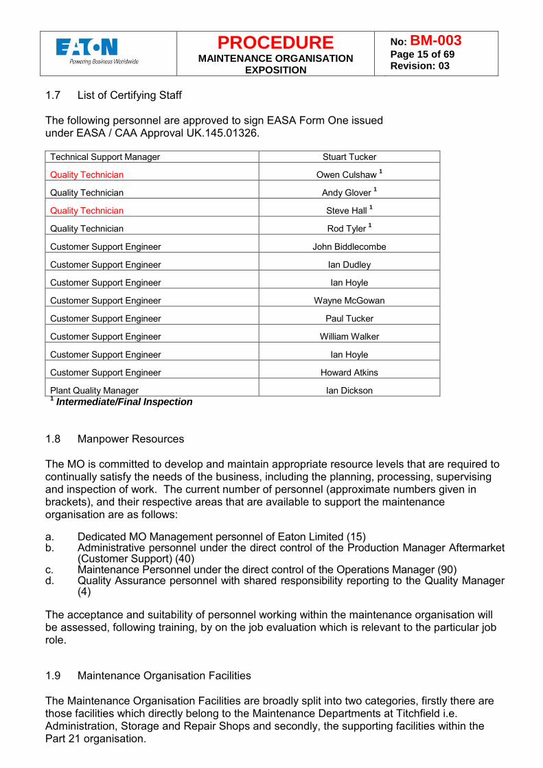
1.7 List of Certifying Staff The following personnel are approved to sign EASA Form One issued under EASA / CAA Approval UK.145.01326. Technical Support Manager Stuart Tucker
Quality Technician Owen Culshaw 1
Quality Technician Andy Glover 1
Quality Technician Steve Hall 1
Quality Technician Rod Tyler 1
Customer Support Engineer John Biddlecombe
Customer Support Engineer Ian Dudley
Customer Support Engineer Ian Hoyle
Customer Support Engineer Wayne McGowan
Customer Support Engineer Paul Tucker
Customer Support Engineer William Walker
Customer Support Engineer Ian Hoyle
Customer Support Engineer Howard Atkins
Plant Quality Manager Ian Dickson 1 Intermediate/Final Inspection
1.8 Manpower Resources The MO is committed to develop and maintain appropriate resource levels that are required to continually satisfy the needs of the business, including the planning, processing, supervising and inspection of work. The current number of personnel (approximate numbers given in brackets), and their respective areas that are available to support the maintenance organisation are as follows: a. Dedicated MO Management personnel of Eaton Limited (15) b. Administrative personnel under the direct control of the Production Manager Aftermarket
(Customer Support) (40) c. Maintenance Personnel under the direct control of the Operations Manager (90) d. Quality Assurance personnel with shared responsibility reporting to the Quality Manager
(4) The acceptance and suitability of personnel working within the maintenance organisation will be assessed, following training, by on the job evaluation which is relevant to the particular job role. 1.9 Maintenance Organisation Facilities The Maintenance Organisation Facilities are broadly split into two categories, firstly there are those facilities which directly belong to the Maintenance Departments at Titchfield i.e. Administration, Storage and Repair Shops and secondly, the supporting facilities within the Part 21 organisation.
PROCEDURE MAINTENANCE ORGANISATION
EXPOSITION
No: BM-003 Page 16 of 69 Revision: 03
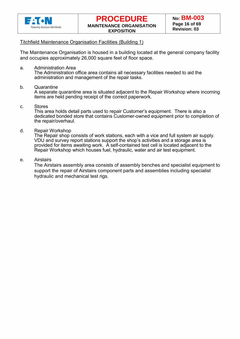
Titchfield Maintenance Organisation Facilities (Building 1) The Maintenance Organisation is housed in a building located at the general company facility and occupies approximately 26,000 square feet of floor space. a. Administration Area
The Administration office area contains all necessary facilities needed to aid the administration and management of the repair tasks.
b. Quarantine
A separate quarantine area is situated adjacent to the Repair Workshop where incoming items are held pending receipt of the correct paperwork.
c. Stores
This area holds detail parts used to repair Customer’s equipment. There is also a dedicated bonded store that contains Customer-owned equipment prior to completion of the repair/overhaul.
d. Repair Workshop
The Repair shop consists of work stations, each with a vice and full system air supply. VDU and survey report stations support the shop’s activities and a storage area is provided for items awaiting work. A self-contained test cell is located adjacent to the Repair Workshop which houses fuel, hydraulic, water and air test equipment.
e. Airstairs
The Airstairs assembly area consists of assembly benches and specialist equipment to support the repair of Airstairs component parts and assemblies including specialist hydraulic and mechanical test rigs.
PROCEDURE MAINTENANCE ORGANISATION
EXPOSITION
No: BM-003 Page 17 of 69 Revision: 03
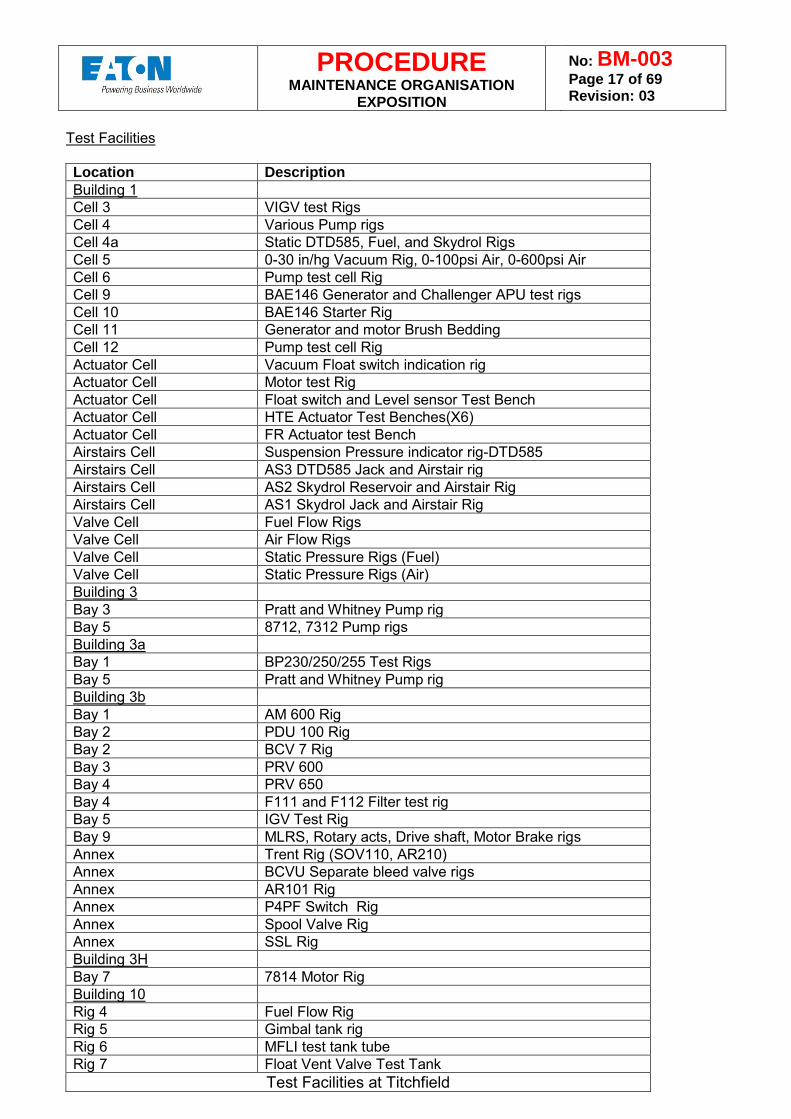
Test Facilities Location Description Building 1 Cell 3 VIGV test Rigs Cell 4 Various Pump rigs Cell 4a Static DTD585, Fuel, and Skydrol Rigs Cell 5 0-30 in/hg Vacuum Rig, 0-100psi Air, 0-600psi Air Cell 6 Pump test cell Rig Cell 9 BAE146 Generator and Challenger APU test rigs Cell 10 BAE146 Starter Rig Cell 11 Generator and motor Brush Bedding Cell 12 Pump test cell Rig Actuator Cell Vacuum Float switch indication rig Actuator Cell Motor test Rig Actuator Cell Float switch and Level sensor Test Bench Actuator Cell HTE Actuator Test Benches(X6) Actuator Cell FR Actuator test Bench Airstairs Cell Suspension Pressure indicator rig-DTD585 Airstairs Cell AS3 DTD585 Jack and Airstair rig Airstairs Cell AS2 Skydrol Reservoir and Airstair Rig Airstairs Cell AS1 Skydrol Jack and Airstair Rig Valve Cell Fuel Flow Rigs Valve Cell Air Flow Rigs Valve Cell Static Pressure Rigs (Fuel) Valve Cell Static Pressure Rigs (Air) Building 3 Bay 3 Pratt and Whitney Pump rig Bay 5 8712, 7312 Pump rigs Building 3a Bay 1 BP230/250/255 Test Rigs Bay 5 Pratt and Whitney Pump rig Building 3b Bay 1 AM 600 Rig Bay 2 PDU 100 Rig Bay 2 BCV 7 Rig Bay 3 PRV 600 Bay 4 PRV 650 Bay 4 F111 and F112 Filter test rig Bay 5 IGV Test Rig Bay 9 MLRS, Rotary acts, Drive shaft, Motor Brake rigs Annex Trent Rig (SOV110, AR210) Annex BCVU Separate bleed valve rigs Annex AR101 Rig Annex P4PF Switch Rig Annex Spool Valve Rig Annex SSL Rig Building 3H Bay 7 7814 Motor Rig Building 10 Rig 4 Fuel Flow Rig Rig 5 Gimbal tank rig Rig 6 MFLI test tank tube Rig 7 Float Vent Valve Test Tank
Test Facilities at Titchfield
PROCEDURE MAINTENANCE ORGANISATION
EXPOSITION
No: BM-003 Page 18 of 69 Revision: 03
The above facilities are supported by test leads for electrically operated valves, calibration controlled pressure gauges and vacuum gauges and transducers. 1.10 Specialist Facilities at Titchfield Metal Finishing Department Extensive metal finishing capabilities are available to support maintenance tasks: Plating consisting of electroless nickel, chrome, nickel, passivation, tin and nickel strike Anodising consisting of sulphuric and chromic Phosphating Alocrom Aluminium polishing Magnesium alloy treatment Vacuum impregnation of castings with polyester resin Painting of cellulose, stove paint, air drying hammer finishes and dry lubricant. Materials Testing Laboratory Facilities for non-destructive testing are tensile, compression, hardness and conductivity testing; non-destructive testing techniques offered are dye penetrant, etch and magnetic particle inspections, ultrasonic, radiographic and eddy current examinations. Chemical Laboratory With full laboratory facilities for monitoring all aspects of the metal finishing/painting facilities. 1.11 Description of Site Buildings at Titchfield The following are the principal buildings which make up the Maintenance organisation: Building Number 1 Comprising of a single-storey building constructed in brick, providing cover and serving to accommodate:
a. The Goods receiving and Maintenance Organisation b. Office accommodation for the Customer Support Department c. The Customer Support warehouse
Supporting Specialist Facilities Facilities which support the maintenance function are tensile, compression, hardness and conductivity testing. Non-destructive testing techniques available are dye penetrant; magnetic particle inspections. General Site Services The site is supported throughout by the following services:
a. Natural gas supply b. AC electricity supply c. The towns’ main water supply d. An effluent treatment plant serving the metal finishing department e. Compressed air system ring mains throughout the site f. DC electrical supply for fuel system component testing.
PROCEDURE MAINTENANCE ORGANISATION
EXPOSITION
No: BM-003 Page 19 of 69 Revision: 03
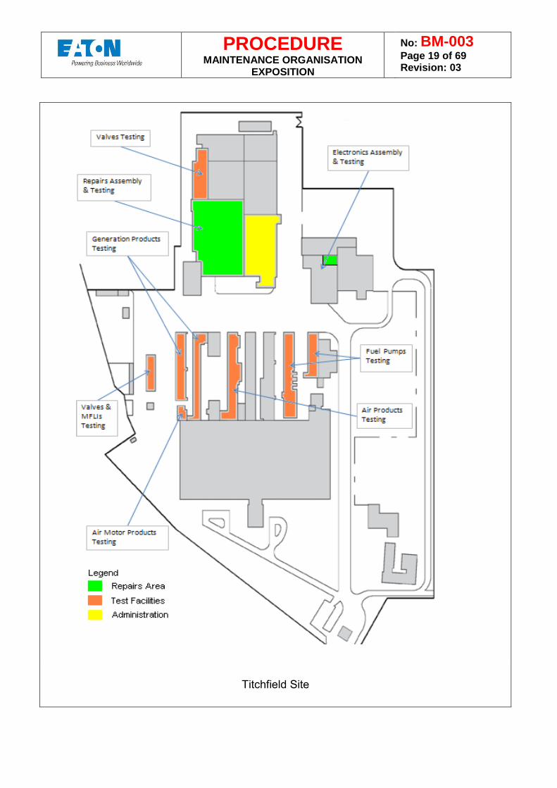
Titchfield Site
PROCEDURE MAINTENANCE ORGANISATION
EXPOSITION
No: BM-003 Page 20 of 69 Revision: 03
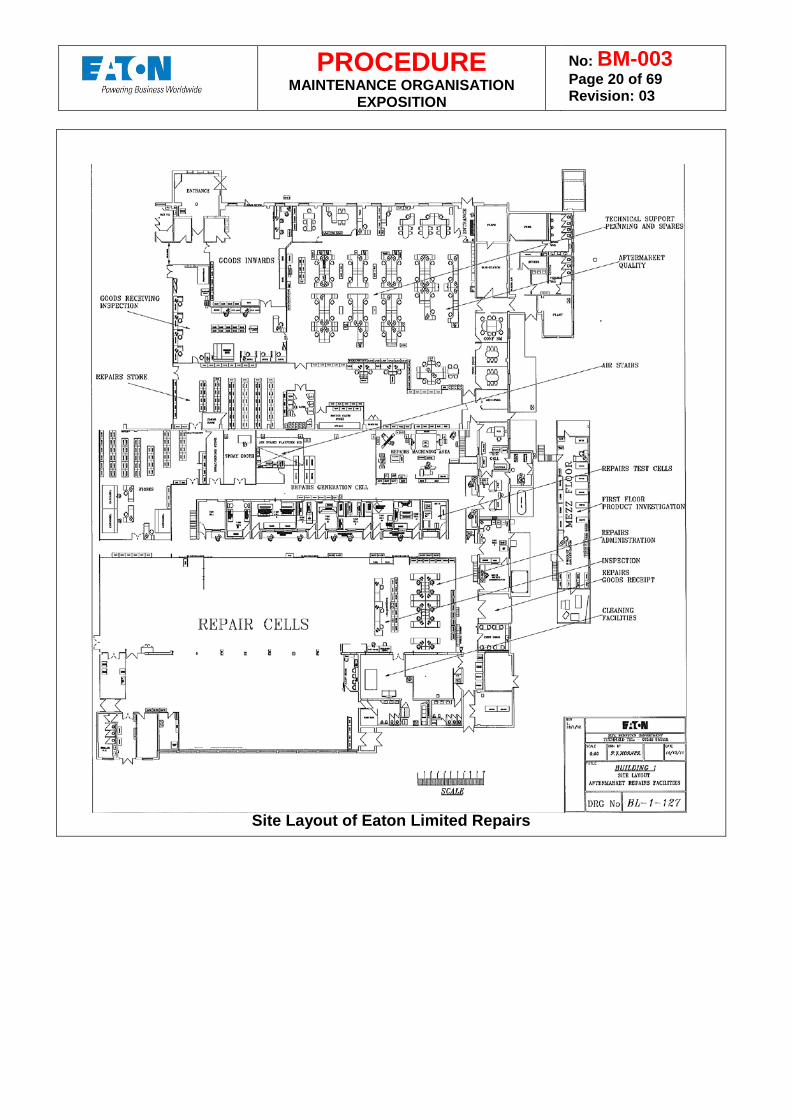
Site Layout of Eaton Limited Repairs
PROCEDURE MAINTENANCE ORGANISATION
EXPOSITION
No: BM-003 Page 21 of 69 Revision: 03
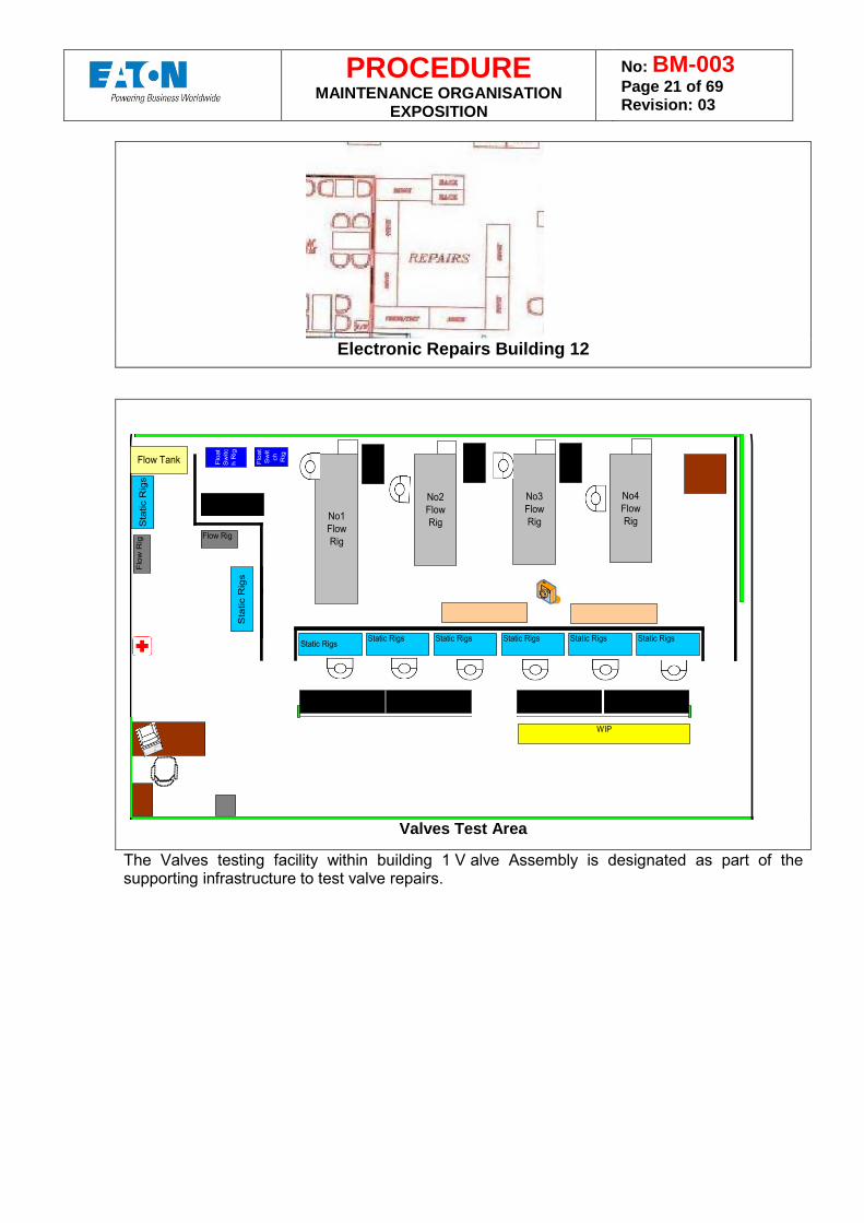
Electronic Repairs Building 12
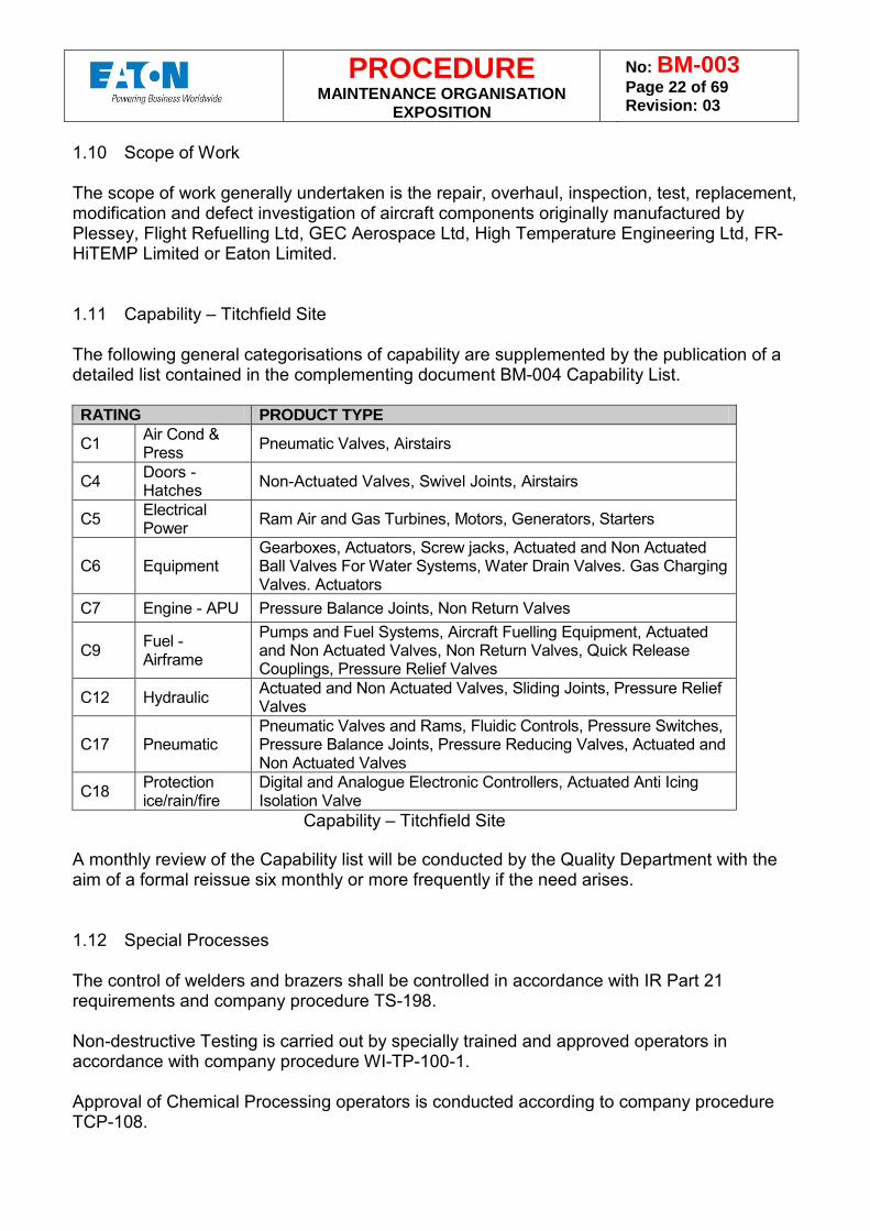
Valves Test Area
The Valves testing facility within building 1 V alve Assembly is designated as part of the supporting infrastructure to test valve repairs.
Static Rigs
No1FlowRig
Flow Tank Flo
at
Sw
itch
R
ig
No2FlowRig
No3FlowRig
No4FlowRig
Flo
at
Sw
itch
Rig
Static Rigs Static Rigs Static Rigs Static Rigs Static Rigs
Sta
tic R
igs
WIP
Sta
tic R
igs
Flow Rig
Flo
w R
ig
PROCEDURE MAINTENANCE ORGANISATION
EXPOSITION
No: BM-003 Page 22 of 69 Revision: 03
1.10 Scope of Work The scope of work generally undertaken is the repair, overhaul, inspection, test, replacement, modification and defect investigation of aircraft components originally manufactured by Plessey, Flight Refuelling Ltd, GEC Aerospace Ltd, High Temperature Engineering Ltd, FR-HiTEMP Limited or Eaton Limited. 1.11 Capability – Titchfield Site The following general categorisations of capability are supplemented by the publication of a detailed list contained in the complementing document BM-004 Capability List. RATING PRODUCT TYPE
C1 Air Cond & Press Pneumatic Valves, Airstairs
C4 Doors - Hatches Non-Actuated Valves, Swivel Joints, Airstairs
C5 Electrical Power Ram Air and Gas Turbines, Motors, Generators, Starters
C6 Equipment Gearboxes, Actuators, Screw jacks, Actuated and Non Actuated Ball Valves For Water Systems, Water Drain Valves. Gas Charging Valves. Actuators
C7 Engine - APU Pressure Balance Joints, Non Return Valves
C9 Fuel - Airframe
Pumps and Fuel Systems, Aircraft Fuelling Equipment, Actuated and Non Actuated Valves, Non Return Valves, Quick Release Couplings, Pressure Relief Valves
C12 Hydraulic Actuated and Non Actuated Valves, Sliding Joints, Pressure Relief Valves
C17 Pneumatic Pneumatic Valves and Rams, Fluidic Controls, Pressure Switches, Pressure Balance Joints, Pressure Reducing Valves, Actuated and Non Actuated Valves
C18 Protection ice/rain/fire
Digital and Analogue Electronic Controllers, Actuated Anti Icing Isolation Valve
Capability – Titchfield Site
A monthly review of the Capability list will be conducted by the Quality Department with the aim of a formal reissue six monthly or more frequently if the need arises. 1.12 Special Processes The control of welders and brazers shall be controlled in accordance with IR Part 21 requirements and company procedure TS-198. Non-destructive Testing is carried out by specially trained and approved operators in accordance with company procedure WI-TP-100-1. Approval of Chemical Processing operators is conducted according to company procedure TCP-108.
PROCEDURE MAINTENANCE ORGANISATION
EXPOSITION
No: BM-003 Page 23 of 69 Revision: 03
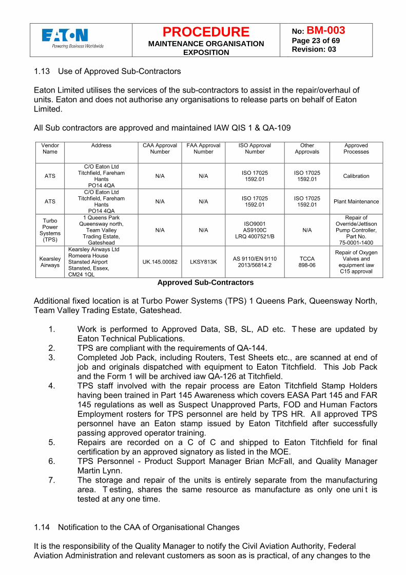
1.13 Use of Approved Sub-Contractors Eaton Limited utilises the services of the sub-contractors to assist in the repair/overhaul of units. Eaton and does not authorise any organisations to release parts on behalf of Eaton Limited. All Sub contractors are approved and maintained IAW QIS 1 & QA-109
Vendor Name
Address CAA Approval Number
FAA Approval Number
ISO Approval Number
Other Approvals
Approved Processes
ATS
C/O Eaton Ltd Titchfield, Fareham
Hants PO14 4QA
N/A N/A ISO 17025 1592.01
ISO 17025 1592.01 Calibration
ATS
C/O Eaton Ltd Titchfield, Fareham
Hants PO14 4QA
N/A N/A ISO 17025 1592.01
ISO 17025 1592.01 Plant Maintenance
Turbo Power
Systems (TPS)
1 Queens Park Queensway north,
Team Valley Trading Estate,
Gateshead
N/A N/A ISO9001 AS9100C
LRQ 4007521/B N/A
Repair of Override/Jettison Pump Controller,
Part No. 75-0001-1400
Kearsley Airways
Kearsley Airways Ltd Romeera House Stansted Airport Stansted, Essex, CM24 1QL
UK.145.00082 LKSY813K AS 9110/EN 9110 2013/56814.2
TCCA 898-06
Repair of Oxygen Valves and
equipment iaw C15 approval
Approved Sub-Contractors
Additional fixed location is at Turbo Power Systems (TPS) 1 Queens Park, Queensway North, Team Valley Trading Estate, Gateshead.
1. Work is performed to Approved Data, SB, SL, AD etc. T hese are updated by
Eaton Technical Publications. 2. TPS are compliant with the requirements of QA-144. 3. Completed Job Pack, including Routers, Test Sheets etc., are scanned at end of
job and originals dispatched with equipment to Eaton Titchfield. This Job Pack and the Form 1 will be archived iaw QA-126 at Titchfield.
4. TPS staff involved with the repair process are Eaton Titchfield Stamp Holders having been trained in Part 145 Awareness which covers EASA Part 145 and FAR 145 regulations as well as Suspect Unapproved Parts, FOD and Human Factors Employment rosters for TPS personnel are held by TPS HR. A ll approved TPS personnel have an Eaton stamp issued by Eaton Titchfield after successfully passing approved operator training.
5. Repairs are recorded on a C of C and shipped to Eaton Titchfield for final certification by an approved signatory as listed in the MOE.
6. TPS Personnel - Product Support Manager Brian McFall, and Quality Manager Martin Lynn.
7. The storage and repair of the units is entirely separate from the manufacturing area. T esting, shares the same resource as manufacture as only one uni t is tested at any one time.
1.14 Notification to the CAA of Organisational Changes It is the responsibility of the Quality Manager to notify the Civil Aviation Authority, Federal Aviation Administration and relevant customers as soon as is practical, of any changes to the
PROCEDURE MAINTENANCE ORGANISATION
EXPOSITION
No: BM-003 Page 24 of 69 Revision: 03
following information which could affect the recorded terms of approval and to satisfy the Agency's requirements for the retention of the approval in the changed circumstances: a. The name of the organisation b. The location of the organisation c. Any additional locations from which the organisation supports work registered under the
scope of approval d. The Accountable Manager e. Any of the senior personnel specified in section 1.3 f. The facilities, equipment, tools, materials and procedures In the first instance, notification of any significant change will be made by telephone. The authority will be kept aware of progress during the migration process. Formal notification will be made in writing (by letter) to the authority as directed by the person nominated by the authority. Any change of planned work scope will be advised in full to the authority.
1.15 Exposition Revision Procedure The Plant Manager UK and the Quality Manager are jointly responsible for the continuous review of this document and will ensure that it constantly reflects the Maintenance Organisation in operation and the latest amendments of IR Part 145. Document revisions will only be issued to registered holders of the document, although the document is available to all employees via the company Intranet Site. As appropriate, document revisions are approved by each Airworthiness Authority prior to formal issue. The Quality Manager is responsible for the review of the revisions. Once reviewed a draft copy the whole document will be prepared and submitted to the Civil Aviation Authority and/or Federal Aviation Authority (as applicable) for acceptance. When acceptance has been granted, final copies will be prepared, including insertion of approval signatures, at the correct issue status and distributed to the authorities and documented holders. When changes are made to the Exposition that might affect compliance with the IRs, such changes must be accepted by the Civil Aviation Authority on before they are incorporated. All revisions shall be identified on the document issue record.
PROCEDURE MAINTENANCE ORGANISATION
EXPOSITION
No: BM-003 Page 25 of 69 Revision: 03
PART 2 - MAINTENANCE PROCEDURES 2.1 Supplier Evaluation and Control The Maintenance Organisation does not have a s eparate supplier evaluation and control system. The Eaton Limited system, which is approved by the Civil Aviation Authority and meets IR Part 21 requirements, is used for all parts purchased for the Maintenance Organisation. Only those suppliers which are listed in EASA Part 21 Production Organisation Approvals listing, or which have undergone an evaluation of their quality management systems and have subsequently been registered as 'Approved Suppliers' will be us ed to supply goods and services. The procedures used in the control of suppliers are described within the relevant Company Control Procedures (QA-109, GM-101, and QIS 1) which form part of the Quality Management System of the company. These procedures will control vendors supplying material used for the maintenance of civil aircraft components. 2.2 Acceptance / Inspection of Purchased Parts The Maintenance Organisation does not have a separate system for the acceptance/inspection of purchased parts. The Eaton Limited system, which is approved by the EASA and meets IR Part 21 requirements, is used for the acceptance/inspection of purchased parts used in the Maintenance Organisation. Material and components supplied by outside contractors/suppliers will be inspected on receipt, to ensure compliance with the requirements of the appropriate Airworthiness Requirements. Orders will only be placed on 'Approved Suppliers' for aircraft parts and materials as above in Para 2.1. Form 1 release will be required for all New and Used non-standard parts that are bought for the MO. C of C release will be acceptable for Standard Parts. The control of the acceptance and inspection of aircraft parts and materiel is prescribed in appropriate Company Control Procedure GM-101. All incoming goods purchased under specified quality requirements will be formally accepted upon satisfactory verification and a record of this acceptance retained. Materials and components delivered to Eaton Limited are either subject to a 'goods inwards' inspection by inspectors authorised by the Plant Quality Manager or delegated source inspection. Inspection will ensure that all items are properly packaged, in good condition and that all the documentation is of a standard satisfactory to the requirements of the EASA or any other regulatory authority as applicable. Delivered goods which fail to meet the requirements of the Company or regulatory authorities will be treated as non-conforming and dispositioned in accordance with procedure QA-163. Materials or components failing to meet the required standards will be quarantined until the deficiencies are resolved. If the deficiencies cannot be resolved, the items will be returned to the supplier or scrapped locally as advised by the supplier. The Supplier will be informed to ensure that the deficiencies do not recur.
PROCEDURE MAINTENANCE ORGANISATION
EXPOSITION
No: BM-003 Page 26 of 69 Revision: 03
2.3 Storage tagging and release of aircraft components All parts in process through the MO will be properly stored in secure areas. They will be identified by use of appropriate tags or placed in suitable identified containers to assure that all parts for each unit will be appropriately segregated from other units and protected from damage or contamination. When the Repair Technician or Repair Administrator considers a component to be Beyond Economical Repair (BER), the component is quarantined and the Customer advised accordingly. Following Customer instruction, the component is either returned in the “as-received” condition or the component is appropriately identified and scrapped on site, see section 2.4 below. The procedures for the storage and issue of aircraft components to the Repair Department are described in Procedure CS-171. After Final Inspection, batches of detail items are accepted into the Customer Support warehouse on a given Job Card Number/Bin Number that forms part of the traceability loop. The items are then held in the store in a manner that affords adequate protection, in accordance with standard Eaton Limited procedures, until they are required for use by either the Maintenance or Production Organisation. The Job Card Number/Bin Number of any item used during the repair operation will be recorded on the repair documentation to form part of the repair history of that assembly. 2.4 Scrap Scrap items not returned to the customer are suitably identified, mutilated and disposed of in a locked scrap bin as prescribed in the appropriate Company Control Procedure CS-171. A scrap certificate is issued to the Customer, confirming their instructions. 2.5 Acceptance of Tools and Equipment The control of tools and equipment is addressed in standard Company Control Procedure GM-146 and incorporates the control of both OEM Part 21 and Part 145 specified tooling. Only tooling specified in the relevant CMM or other controlling documents will be utilised. The organisational aspects for effecting the necessary controls and procedures are the responsibility of the Plant Manager Aftermarket. 2.6 Use of tooling and equipment by staff (including alternate tools) The use of tooling and equipment is prescribed for each item in either of the following documents: a. The Component Maintenance Manual b. The Production Acceptance Test Procedure (PAT) c. The component drawing
PROCEDURE MAINTENANCE ORGANISATION
EXPOSITION
No: BM-003 Page 27 of 69 Revision: 03
Tool numbers are referenced back to the tool drawing, giving both the OE reference and the CMM tool reference. Any specialist equipment requiring specific training for correct use will be identified and the adequate operator training will be arranged and recorded on personnel training records by the MTMR. The maintenance organisation does not use alternative tooling. Only tools specified by the approved data CMM / drawing) are utilised in repairing items 2.7 Cleanliness Standards of Maintenance Facilities Within the confines of the Maintenance facilities, it is Company Policy to segregate the 'dirty' areas from the clean condition areas.
The dirty areas, such as disassembly, de-contamination, cleaning and lapping of component parts will be segregated to ensure that no contact with parts for re-assembly will occur. The assembly areas have a controlled environment; smoking and the consumption of food and drink are not allowed. This is in accordance with the applicable company policy as maintained through the company human resource department. Where special assembly conditions are required by the Component Maintenance Manual, such as those used in an oxygen valve assembly, clean condition areas as used during initial manufacture will be utilised. 2.8 Maintenance Instructions Eaton Limited Maintenance Instructions Maintenance instructions for new product (i.e. new OEM product being developed as part of a design & supply contract), will be developed alongside the production assembly instructions and verified/implemented using the business project management tool ProLaunch which is accessible via the company Intranet system. This is a gated review process that ensures appropriate interfaces exist between the Design and the Maintenance Organisations. It also controls the information flow and timing to ensure that applicable data is available at the correct time. Maintenance instructions in the form of Component Maintenance Manuals and Service Bulletins are produced to eSpec2200 and updated by the Eaton Limited Technical Publications department for all those items for which Eaton Limited has the design responsibility. These documents are available throughout the maintenance process and are updated as a result of design changes, changes caused by observations during their use or for other reasons reported to Eaton Limited which has airworthiness implications. Test instructions for Eaton Limited produced equipment not covered in the EASA capability listing will be documented either on the drawing or in the appropriate Production Acceptance Test Procedure (PAT). These are officially controlled documents, which are issued to the Maintenance Organisation by the Data Centre/Library. Other Manufacturers Maintenance Instructions
PROCEDURE MAINTENANCE ORGANISATION
EXPOSITION
No: BM-003 Page 28 of 69 Revision: 03
The local operations managers will be directly responsible for ensuring that all necessary maintenance instructions of the appropriate issue status are made available for all maintenance work undertaken on other manufacturers' equipment. 2.9 Repair Procedures The procedures that control the maintenance work undertaken on civil aircraft equipment are given in detail in procedure CS-171. This procedure defines the complete product lifecycle from preliminary inspection through to product despatch as required for each package of work processed. These procedures are available to all relevant staff involved in such work. Detailed work operations will depend on the requirements and operational sequence prescribed by the survey report and the relevant work instructions and will normally use the CMMs, Component Drawings or the Assembly Plan standard as basic source data. The final testing of repaired units will be carried out either in the Repair Workshop or the Production Test House. The decision on where the test will be carried out will be made by the MTMR and will be based on resource management and the availability of test equipment. In some circumstances, where in-service studies have provided additional information, RRI (Repair and Reconditioning Instructions) may be generated and utilized. These will be generated and sanctioned in accordance with procedure CS-167. 2.10 Aircraft Maintenance Programme Compliance Eaton Limited does not operate, store or maintain complete aircraft or major aircraft assemblies. This subject is therefore not applicable. 2.11 Airworthiness Directives
All publications are reviewed by the site Quality Manager or the nominated Maintenance Organisation Quality Engineer, on a bi-weekly basis via access to the Airworthiness Directives web site(s) of the EASA and the CAA EASA - Aircraft with Type Certificates issued by EASA CAA - Aircraft with Type Certificates issued by the CAA CAA - Mandatory requirements for Aircraft registered in the UK Where there are implications for the approved maintenance organisation, recommendations for action and dissemination will be undertaken and all relevant departments informed. 2.12 Optional Modification Procedure All change control procedures are promulgated under the organisations Configuration Management controls.
PROCEDURE MAINTENANCE ORGANISATION
EXPOSITION
No: BM-003 Page 29 of 69 Revision: 03
2.13 Maintenance Documentation All work will be carried out to approved Component Maintenance Manuals (CMM) or Production Assembly Drawings. A uniquely numbered work documentation package is generated to structure and document all work performed in respect to assigned repair tasks. These documents collectively combine to form the maintenance records for the repair. This package can contain, as appropriate, a Survey Report, Route Card, Strip Report or Build Sheet. Whichever documents are utilised to support a specific repair, each of the following elements will be both stipulated and evidence of completion will be documented and maintained: a. Process requirements (paint shop, treatment). b. Detailed list of replacement parts required. c. Assembly procedure requirements, to CMM or component drawings, including the
revision status. d. Test procedure requirements, to CMM or production component test requirements,
including the revision status. e. Inspection requirements. f. Any special requirements. The work package documentation remains with the component at all times during the work process. Operations detailed in the documentation will be signed or stamped, as appropriate, as and when they are completed. Special Reports (Product Investigation Report, Repair Engineering Report, Repair Condition Report), when requested by the customer or company, are compiled from the information contained against the relevant repair work order. They contain all relevant basic information regarding the repair together with the investigation results/conclusions and any corrective/preventive action that is considered necessary. 2.14 Storage of Maintenance Records Maintenance Records are stored for a minimum period as defined within company procedures QA-126 and QA-241. This meets the minimum requirement of 3 years from release out of the business. 2.15 Technical Record Control
Technical records including drawings, assembly plan standards and production acceptance test schedules are controlled by a raise of issue system which is described in appropriate Company Control Procedures (CS-109, EN-112). The Maintenance Organisation will also have access to out of issue drawings and copies of change notes to enable any issue of returned components or assembly to be repaired. These documents will be held by configuration control. All records appertaining to a particular repair order will be initially filed in the Maintenance Department before being transferred to the company archives. The records will include the following: The Repair Order
PROCEDURE MAINTENANCE ORGANISATION
EXPOSITION
No: BM-003 Page 30 of 69 Revision: 03
Contract Review Sheet Repair documentation Condition/Investigation Report EASA Form 1 Any customer correspondence The above records will be maintained for a minimum period of seven years. 2.15 Rectification of Defects arising during base maintenance
Eaton Limited does not operate, store or maintain complete aircraft or major aircraft assemblies. This subject is therefore not applicable. 2.16 Release to Service Procedures An EASA Form 1 (Appendix 11) will accompany all items released to service. This procedure is described in detail in appropriate Company Control Procedures (QA-222). The EASA Form 1 is generated electronically via the business MRP system. Any changes to the system that may affect the generation of the EASA Form 1 will be tested prior to release. Changes to the Form 1 will be notified to the authority and accepted prior to integration. 2.17 Records for the Operator Eaton Limited does not operate, store or maintain complete aircraft or major aircraft assemblies. This subject is therefore not applicable. 2.18 Reporting Defects to the Competent Authority / Operators / Manufacturer All personnel within the Maintenance Organisation are conscious of the requirements of the Mandatory Occurrence Reporting Scheme. The specific elements of the process of reporting are defined, as appropriate, within Company Control Procedures (CS-171, QA-P-010). Adequate supplies of the MOR form (CAA Form SRG/1601) are made available so that anyone throughout the organisation can raise a report. Once a report has been raised, it will be passed to the Quality Manager who will evaluate the content and where appropriate initiate corrective action and forward it to the Civil Aviation Authority. The report shall be submitted to the Civil Aviation Authority within 72 hours. 2.19 Return of Defective Aircraft Components to Store If during the course of the repair procedure it is considered that it is uneconomical to proceed further the item together with the documentation package will be placed in the Quarantine Store pending disposal instructions from the customer. 2.20 Defective Components to Outside Contractor When it is necessary to return a component or component part to a sub-tier supplier for repair/investigation the following procedure will apply:
PROCEDURE MAINTENANCE ORGANISATION
EXPOSITION
No: BM-003 Page 31 of 69 Revision: 03
Repair Administration will raise a Request to Order detailing the work required and all necessary requirements including any investigation and/or test reports. Eaton Limited Purchasing Department will raise purchase order on the sub-tier supplier in accordance with Purchasing Manual. Eaton Limited Repair Administration will raise a Shipping Requisition and process the item to the Despatch Department who will return the item to the sub-tier supplier. After completion of the work by the sub-tier supplier, the component or component part will be returned to Eaton Limited where it will be routed through Eaton Limited Goods-In Department and transferred to the Repair Department in accordance with GM-101 2.21 Control of the Computer Maintenance Record System Within Eaton Limited Maintenance Organisation, computer systems are only used to generate the repair number, the repair documentation, the condition/investigation report and the release documentation. It is a requirement that hard copies of all these documents are held in the Maintenance Organisation’s filing system for a minimum period of seven years. Computer systems are protected by security passwords to provide safeguards against unauthorised access. Electronic information back-ups are undertaken by the business Information Technology department(s) to ensure comprehensive storage and retrieval of documents. 2.22 Control of Man-Hour Planning versus Scheduled Maintenance Work In planning of maintenance tasks and the organising of shifts, human performance limitations are taken into consideration. 2.23 Control of Critical Tasks Human factors and human performance are reviewed as part of personnel development in accordance with AC145-10 “Repair Station Training Program”. 2.24 Reference to Specific Maintenance Procedures Eaton Limited, at this time, is not required to develop and promulgate any specific maintenance procedures or deviation form. 2.25 Procedures to Detect and Rectify Maintenance Errors The Repair Technicians carry out self-inspections, this is identified on the build sheet when the Technician stamps or signs off the operations that have been conducted. All final assemblies are passed through 100% final inspection. This is carried out by an Inspection team independent of the repairs process.
PROCEDURE MAINTENANCE ORGANISATION
EXPOSITION
No: BM-003 Page 32 of 69 Revision: 03
2.26 Shift / Task Handover Procedures Human factors and human performance are reviewed as part of personnel development. During any hand over periods all relevant information is communicated between outgoing and incoming personnel, this information is controlled via the Team Leaders in accordance with management techniques. Eaton Limited operates a core and late shift, and when required a shift handover book is used for the transfer of tasks between personnel. Each repair technician undertakes a defined repair at their own workbench. All technicians must ensure that the repair records are maintained up to date with all stages undertaken, accepted by signature/stamp of the repair record paperwork. Where a repair task is handed over to another repair technician, the repair record pack will form the basis of the handover, indicating stages completed and the next steps. Additionally, where applicable, the Repair Technician going off shift / task will verbally communicate the stage of repair and on-going activities required to complete the repair tasks. 2.27 Procedure for Notification of Maintenance Data Inaccuracies and Ambiguities to the
Type Certificate Holder. Component Maintenance Manuals (CMM’s) are reviewed and maintained to incorporate amendments that have resulted from data inaccuracies and ambiguities. The CMM’s are forwarded to the relevant type certificate holders and authorities for approval prior to formal issue. Where inaccuracies and ambiguities are noted in CMM’s for which Eaton Limited do not own design responsibility, the responsible manual owner will be notified.
PROCEDURE MAINTENANCE ORGANISATION
EXPOSITION
No: BM-003 Page 33 of 69 Revision: 03
PART L2 – ADDITIONAL LINE MAINTENANCE PROCEDURES With the exception of Part L2.3, repair approval for the remainder of this section is not being sought. Consequently, the following sections are deemed as not applicable. L2.1 Line Maintenance Control of Aircraft Components, Tools, Equipment etc. Not applicable. L2.2 Line Maintenance Procedures related to deviation / Fuelling / De-Icing etc. Not applicable.
L2.3 Line Maintenance Control of Faults and Repetitive Faults Off-site support of this company’s products is the responsibility of the Customer Support Department. A full service is provided, including Support Engineering, Technical Publications, Spares back-up, Carrier liaison, field data retrieval, analysis and dissemination (CS-170). Close liaison exists between Customer Support and the rest of the business. Regular visits are made to users and assistance is provided to resolve problems, set up Repair and Overhaul facilities and answer queries. Statistics are produced which enable monitoring of Product Reliability in service and the early detection of adverse trends in operation (CS-121). Support Engineers working off-site hold certificates of authorisation, duly approved and signed by the Quality Manager, delegating responsibility for the undertaking of Inspection, Overhaul, Repair, Replacement, Modification and Rectification of parts and equipment manufactured by this company (CS-170). A full assessment of the task before a visit is conducted by the Technical Manager/Support Engineers and establishes the Tools, Equipment and Work Instruction requirements needed to satisfactorily complete the work. Notification is given to the customer to establish any needs concerning environment and facilities. No excursions from the specified limits of knowledge, tools or job function, is allowed unless agreed and verified with the customer. All work is to be carried out within the limits and in accordance with Drawings or Overhaul, Repair and Maintenance Manuals, unless authorised through the concession process, ref QA-163. Following work undertaken away from the Maintenance Organisation, a Certificate of Work Undertaken document, describing exactly the nature of the work done, modifications incorporated or deleted, serial number of parts fitted and removed, is completed and duly signed and stamped by the Support Engineer. On receipt of this document by the Sales & Marketing function of Customer Support, the relevant Release to Service documentation is prepared and authorised by the Company Certifying Staff prior to submission to the Customer. For detailed information on the process used, guidance can be gained from the appropriate Company Control Procedures (CS-121, QA-222)
PROCEDURE MAINTENANCE ORGANISATION
EXPOSITION
No: BM-003 Page 34 of 69 Revision: 03
L2.4 Line Procedure for Completion of Technical Log Not applicable.
L2.5 Line Procedure for Pooled Part and Pooled Parts
Not applicable. L2.6 Line Procedure for return of Faulty Parts Removed from Aircraft
Not applicable.
PROCEDURE MAINTENANCE ORGANISATION
EXPOSITION
No: BM-003 Page 35 of 69 Revision: 03
PART 3 – QUALITY SYSTEM PROCEDURES 3.1 Quality Audit of Maintenance Organisation The Quality Manager, Titchfield will implement a planned programme of audits covering the whole Eaton Limited facility. The audit programme will monitor the effectiveness of the organisation’s quality system and seek objective evidence that documented management procedures are being followed. Specific details of the processes employed can be found in standard Company Control Procedures (QA-P-004). 3.2 Management Review General The Eaton Limited management team reviews the Quality Management System at least twice per year to ensure its continuing suitability, adequacy and effectiveness. This review evaluates any need for changes to Eaton Limited’s Quality Management System, including the Quality Policy and quality objectives. Review Input Input to management review includes current performance and improvement opportunities related to the following:
a. Audit results; b. Feedback from internal and external customers; c. Process performance and product conformance; d. Status of preventive and corrective actions; e. Follow-up actions from earlier management reviews; f. Changes that could affect the Quality Management System; g. Recommendations for improvement; h. New legislation and technology.
Review Output The outputs from the management review will include actions related to the:
a. Improvement of the Quality Management System and its processes; b. Improvement of product related to customer requirements; c. Resource needs; d. Results of management reviews are recorded and maintained.
3.3 Quality Audit of Aircraft
Eaton Limited does not operate, store or maintain complete aircraft or major aircraft assemblies. This subject is therefore not applicable.
3.4 Quality Audit Remedial Action Procedure
Non-conformances recorded against the maintenance organisation management procedures shall be subject to corrective action by the Quality Manager. The Quality Manager will arrange follow up audits in order to review the effectiveness of corrective
PROCEDURE MAINTENANCE ORGANISATION
EXPOSITION
No: BM-003 Page 36 of 69 Revision: 03
action taken. Unsatisfactory situations will be further investigated and if the non-conformance continues to persist, the audit will be referred to the Director concerned.
3.5 Certifying Staff Qualification and Training Qualification of Certifying Staff In order to qualify for certifying staff status, staff are required to have the appropriate experience, qualification and where necessary training to the satisfaction of the Quality Manager. Furthermore, such staff must be familiar with the product, general inspection procedures, and relevant airworthiness requirements. The Quality Manager is responsible for developing, implementing and reviewing the training plan for certifying staff in accordance with Company Control Procedures (QA-222). The review will determine any continuation training that may be required. Continuation training shall include product or technology training to support the certifying staff member with regards to making a determination of the airworthiness of a product (e.g. when new technologies are introduced into products). Approval and Authorisation of Certifying Staff Approval of certifying staff will initially be undertaken by the Quality Manager in accordance with procedure QA-222. Experience Records Experience records shall be completed by all certifying staff and reviewed on a two yearly basis by the Quality Manager, to determine continual approval. 3.6 CERTIFYING STAFF RECORDS Certifying staff qualification and training will be recorded on personnel authorisation forms and will be reviewed annually. The Quality Manager will hold copies of records, for audit purposes and a copy held by each certifying person. Employment history of Certifying Staff is held in the Human Resources department. The forms contain the following information:
a. Name b. Date of birth c. Basic training d. Type training e. Continuation Training f. Experience g. Qualification relevant to the approval h. Scope of Authorisation i. Date of first issue of authorisation j. If appropriate - expiry date of the authorisation k. Identification number of the authorisation.
A list of certifying staff is maintained by the Quality Engineering department and can be found in BM-006 & QA-222 and is available on the Company Intranet. Changes to the certifying staff list will be updated within 5 working days.
PROCEDURE MAINTENANCE ORGANISATION
EXPOSITION
No: BM-003 Page 37 of 69 Revision: 03
3.7 Quality Audit Personnel Auditors undergo training to such a level as to be authorised to undertake management system and product audits throughout the organisation in accordance with standard Company Control Procedures (QA-P-004). 3.8 Qualifying Inspectors The Supervisor/Inspector will carry out mechanical inspection procedures within the Maintenance Organisation. The Inspector/Fitter (Electrical) will carry out electrical Inspection within the Maintenance Organisation. All Supervisors/Inspectors are holders of appropriate stamps and the Quality Manager is responsible for the control and issue of authorising stamps. Individuals are responsible for ensuring their stamps are legible. The supervisor/Inspector may delegate inspection operations to the Works Inspection Department who will operate within existing inspection procedures. The MTMR is responsible for developing, implementing and reviewing the training plan for staff carrying out inspection functions within the Maintenance Organisation, but an authorising stamp will only be issued by the Quality Manager when he is satisfied that the degree of training is adequate for the proposed role of the individual. The review will determine any continuation training that may be required. Procedure QA-186 refers. Continuation training shall include product or technology training to support the Inspector in making a determination as to the conformity of a product (e.g. when new technologies are introduced into products). 3.9 Qualifying Technicians The Plant Manager Aftermarket is responsible for developing, implementing and reviewing the training plan for fitters working within the Maintenance Organisation. The review of the training plan will determine any continuation training that may be required. All Repair Technicians will be trained to enable them to operate without constant independent inspection involvement and such training will be conducted in accordance with relevant Company Control Procedures (QA-185). All products will be subjected to Final Inspection activity by an independent inspection staff member, except in the case where a self-certifier is employed. As a self-certifier, a Repair Technician is authorised to self-certify his own work without the need for an independent review by Inspection Department staff. All self-certifiers are subject to an audit programme to establish their ongoing competency. The MRO Training Co-ordinator holds copies of all qualifying technicians’ records of training and approvals held.
PROCEDURE MAINTENANCE ORGANISATION
EXPOSITION
No: BM-003 Page 38 of 69 Revision: 03
3.10 Exemption Process Control If any exemption to the process control is necessary then Eaton Limited will apply to the EASA for approval to work outside the requirements of IR Part 145.
3.11 Concession Control Non-conforming material will be subject to review and disposition via Material Review Board (MRB) in accordance with company procedure QA-163 (Control of Non-conforming Material). The MRB will include personnel from Engineering, Quality and the Maintenance Organisation, where in-service and maintenance compatibility, life, interchangeability, etc. will be considered. The MRB may disposition the material as either use as-is via a concession (production permit/waiver/deviation), or scrap (i.e. remove from the system and dispose of via permanent deformation on-site or returned to supplier for review). If, during a repair, there is a requirement for a concession it will be actioned in accordance with relevant Company Control Procedure (QA-163, WI-QA-163-3) and records will be maintained in Customer Support. 3.12 Qualification Procedure for Specialist Activities Materials Laboratory The Maintenance Organisation's operation can be supported by the company’s materials laboratory. Welding Certification of welders to undertake welding techniques on aircraft components under the authority of the Civil Aviation Authority (CAA) is granted by materials laboratory staff holding appropriate qualifications. Training and certification requirements for welding personnel are defined in standard Company Control Procedures TS-198. Records of approval are maintained. Non Destructive Testing (NDT) NDT personnel hold either EN4179 or EN473 certification for the appropriate NDT techniques they are authorised to undertake. Training procedures for NDT personnel are contained in Company Procedure WI-TP-100-1. 3.13 Control of Manufacturers Working Parties Within the maintenance organisation each working cell is managed by a responsible team leader, whose responsibilities are to ensure on-going compliance to approved processes and procedures in accordance with regulatory approvals. This process ensures ongoing continuity across the working teams within each cell. Detailed responsibilities, authority and procedures are contained in Company Control Procedure CS-171.
PROCEDURE MAINTENANCE ORGANISATION
EXPOSITION
No: BM-003 Page 39 of 69 Revision: 03
3.14 Human Factors Training Programme Research and experience have shown that Human Factors training can address many of the issues that contribute to events. Training can reduce costs associated with human performance issues. Why Human Factors Training is important
a. Human Factors training is instrumental in fostering a positive safety culture. b. Human Factors training for the workforce, including for the leadership is a critical
and cost-effective first step in identifying methods to recognize, understand, and manage human performance issues.
c. Effective Human Factors training not only improves work performance, but also promotes workforce physical and psychological health.
d. Initial and recurrent training on new regulations, procedures, and equipment are opportunities to reinforce awareness of the Human Factors issues that affect job performance.
e. ICAO and many NAAs mandate or recommend Maintenance Human Factors training, recognizing its impact on safety and quality.
Human Factors Training programme
a. General/introduction to Human Factors. b. Safety culture/organizational factors. c. Human error principles, event investigation and case studies. d. Human performance and limitations. e. Environment. f. Procedures, information, tools and task sign-off practices. g. Planning of tasks, equipment, and spares. h. Communication. i. Teamwork. j. Professionalism and integrity. k. Shift and task turnover. l. Undocumented maintenance. m. Fatigue management/fitness for duty.
Requirements and company priorities that map to the key topics listed above.
a. Work to ensure cooperative development between workforce and management. b. Integrate training with a system wide Human Factors plan. c. Decide on content and delivery technique matched to audience requirements. d. Decide on internal/external provider. e. Deliver initial training and begin planning for recurrent training. f. Measure the effects of training, provide feedback to the instructors and the
management, improve training, and measure the effects again.
3.15 EASA Fuel Systems Regulations (CDCCL/SFAR88/FAR 25/981)
In line with the businesses requirements to ensure that full control and awareness of fuel system regulations (SFAR 88/FAR 25/981) for design and maintenance of fuel system
PROCEDURE MAINTENANCE ORGANISATION
EXPOSITION
No: BM-003 Page 40 of 69 Revision: 03
components is adhered to, by all personnel involved in the maintenance of fuel products, the following training must be completed by maintenance personnel in order for them to understand and follow correct procedure whilst conducting maintenance on CDCCL products (for full requirements of training please refer to BM-109). General Requirements of Training General Maintenance (Non-Fuel) Level 1 Human Factor Awareness Level 1 CDCCL Awareness Fuel Maintenance Level 1 Human Factor Awareness Level 1 CDCCL Awareness Level 2 CDCCL Training Phase 1 - Awareness Phase 1 is an awareness course giving a level of familiarization with the principal elements of the subject. It may take the form of a training bulletin, or other self-study or informative session. Signature of the reader is required to ensure that the person has passed the training. The training shall be carried out before the person starts to work without supervision but not later than 6 months after joining the organization. The persons who have already attended the Level 1 awareness course in compliance with ED decision 2007/002/R Appendix IV is already in compliance with Phase 1. Phase 2 - Detailed Training Phase 2 is a more in-depth internal or external course on the theoretical and practical elements of the subject. It should not take the form of a training bulletin, or other self-study. An examination is required at the end, which should be in the form of a multiple choice questionnaire, and the pass mark of the examination is 75%. The persons who have already attended the Level 2 training course in compliance with ED decision 2007/002/R Appendix IV either from a Part-145 maintenance organization or from a Part-147 training organization are already in compliance with Phase 2 with the exception of continuation training. Continuation Training The organization shall ensure that continuation training for all required personnel is conducted within a two year period. The continuation training may be combined with the Phase 2 training. The continuation training will be updated when new instructions are issued which are related to the material, tools, documentation and manufacturer’s or competent authority’s directives. 3.16 Extension of Quality System to Subcontractors If during the course of a repair there is a requirement to subcontract a service or process, then the Eaton Limited purchasing system, which meets the EASA requirements, will be used.
PROCEDURE MAINTENANCE ORGANISATION
EXPOSITION
No: BM-003 Page 41 of 69 Revision: 03
After the requirement for a process or service has been identified, the Repair Administrator will pass the information to the Purchasing Department. The Eaton Limited Purchasing Manual describes the process and controls for raising an order. Purchase orders will only be raised on approved companies, reference the Supplier Control procedure QA-109. When items are returned they will be inspected in the Eaton Limited Goods Inwards Department, reference the Goods-in Inspection procedure GM-101, and the inspection results will be entered onto the Vendor Rating System as described in GM-135 and QA-109.
PROCEDURE MAINTENANCE ORGANISATION
EXPOSITION
No: BM-003 Page 42 of 69 Revision: 03
PART 4 - IR OPS Operators Eaton Limited does not operate, store or maintain complete aircraft or major aircraft assemblies. This subject is therefore not applicable.
PROCEDURE MAINTENANCE ORGANISATION
EXPOSITION
No: BM-003 Page 43 of 69 Revision: 03
PART 5 - APPENDICES Appendix 1 - Level 1 Investigation Report .............................................................................. 44 Appendix 2 - FRACA Sample................................................................................................... 46 Appendix 3 - CAA Occurrence Report (CA1673) ..................................................................... 48 Appendix 4 - Scrap Certificate ................................................................................................. 49 Appendix 5 - Picking List .......................................................................................................... 51 Appendix 6 - Build Sheet ......................................................................................................... 52 Appendix 7 - Test Reject & Rectification Card ......................................................................... 53 Appendix 8 - Test Certificate .................................................................................................... 54 Appendix 9 - EASA Form 1 ...................................................................................................... 55 Appendix 10 - EASA Form 1 Dual (EASA/FAA) Release Certificate........................................ 56 Appendix 11 - EASA Form 1 Dual (EASA/TCCA) Release Certificate ..................................... 57 Appendix 12 - EASA Form 1 Triple (EASA/FAA/TCCA) Release Certificate ........................... 58 Appendix 13 - EASA Form 1 as FAA 8130-3 ........................................................................... 59 Appendix 14 - Certificate of Conformity (C of C) ...................................................................... 60 Appendix 15 - Certifying Staff Authorisation ............................................................................ 61 Appendix 16 - Un-Serviceable Component Tag ....................................................................... 62 Appendix 17 - Inspection Repair Report (Example) ................................................................. 63 Appendix 18 - Inspection Repair Report (Example) (Contd..) .................................................. 64 Appendix 19 - Router (Example) ............................................ 65Error! Bookmark not defined. Appendix 20 - Preliminary Survey Report ................................................................................ 66 Appendix 21 - Employment Summary Form ............................................................................ 67 Appendix 22 - Shelf Life Control Form ..................................................................................... 68 Note Examples of Forms are for reference purposes only.
The master document is subjected to normal operating change controlled procedures which govern revision status.
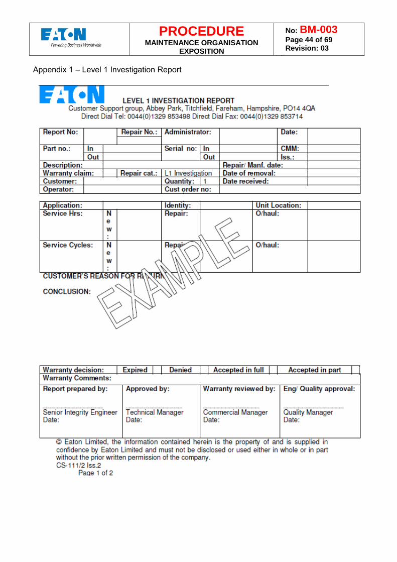
PROCEDURE MAINTENANCE ORGANISATION
EXPOSITION
No: BM-003 Page 44 of 69 Revision: 03
Appendix 1 – Level 1 Investigation Report
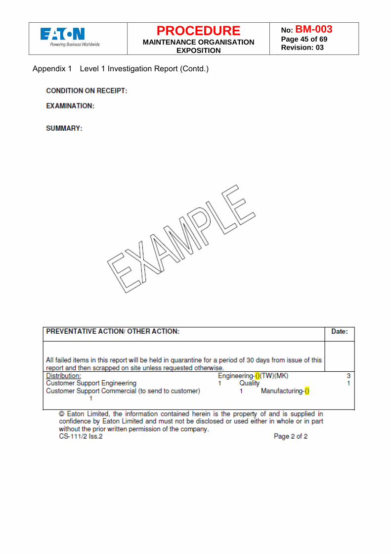
PROCEDURE MAINTENANCE ORGANISATION
EXPOSITION
No: BM-003 Page 45 of 69 Revision: 03
Appendix 1 Level 1 Investigation Report (Contd.)
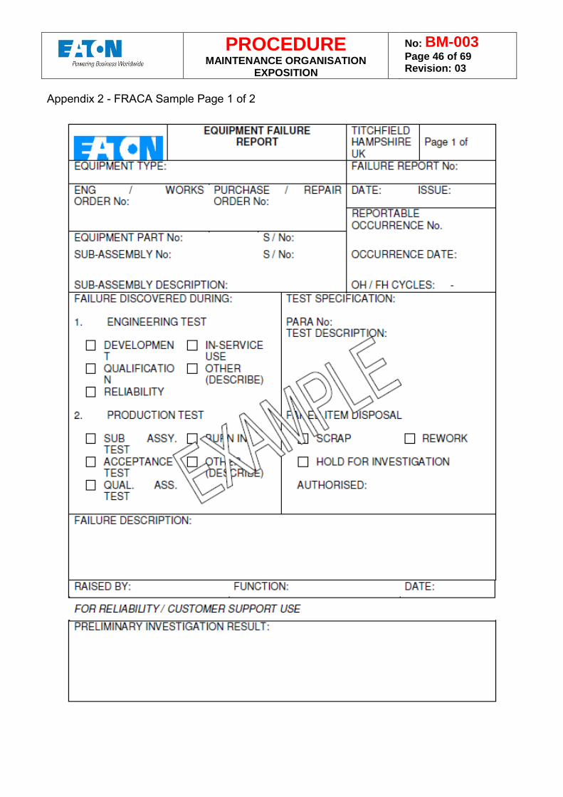
PROCEDURE MAINTENANCE ORGANISATION
EXPOSITION
No: BM-003 Page 46 of 69 Revision: 03
Appendix 2 - FRACA Sample Page 1 of 2
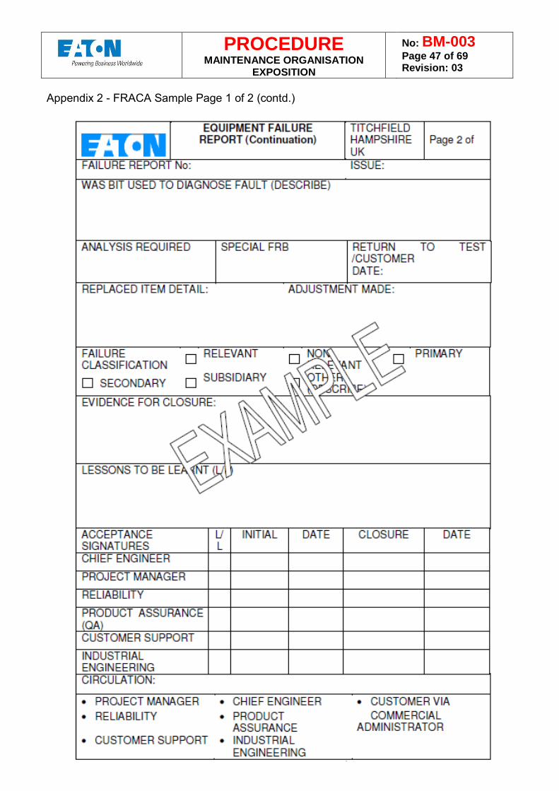
PROCEDURE MAINTENANCE ORGANISATION
EXPOSITION
No: BM-003 Page 47 of 69 Revision: 03
Appendix 2 - FRACA Sample Page 1 of 2 (contd.)
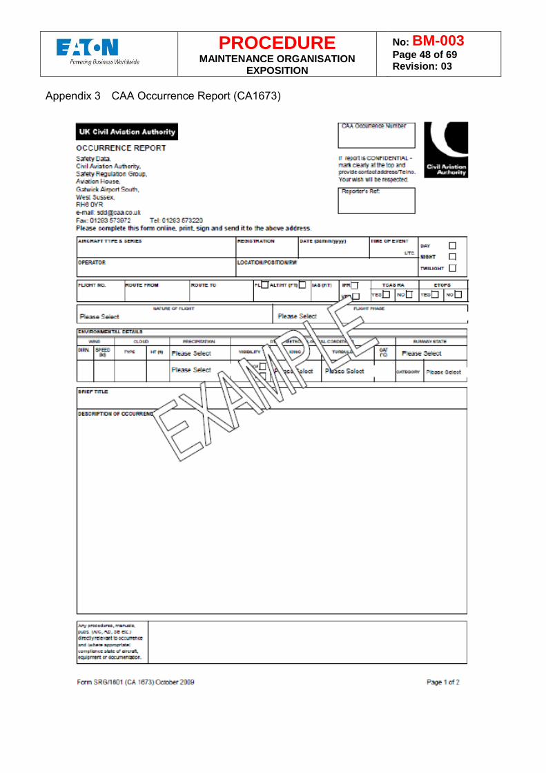
PROCEDURE MAINTENANCE ORGANISATION
EXPOSITION
No: BM-003 Page 48 of 69 Revision: 03
Appendix 3 CAA Occurrence Report (CA1673)
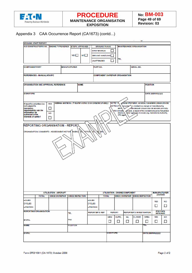
PROCEDURE MAINTENANCE ORGANISATION
EXPOSITION
No: BM-003 Page 49 of 69 Revision: 03
Appendix 3 CAA Occurrence Report (CA1673) (contd...)
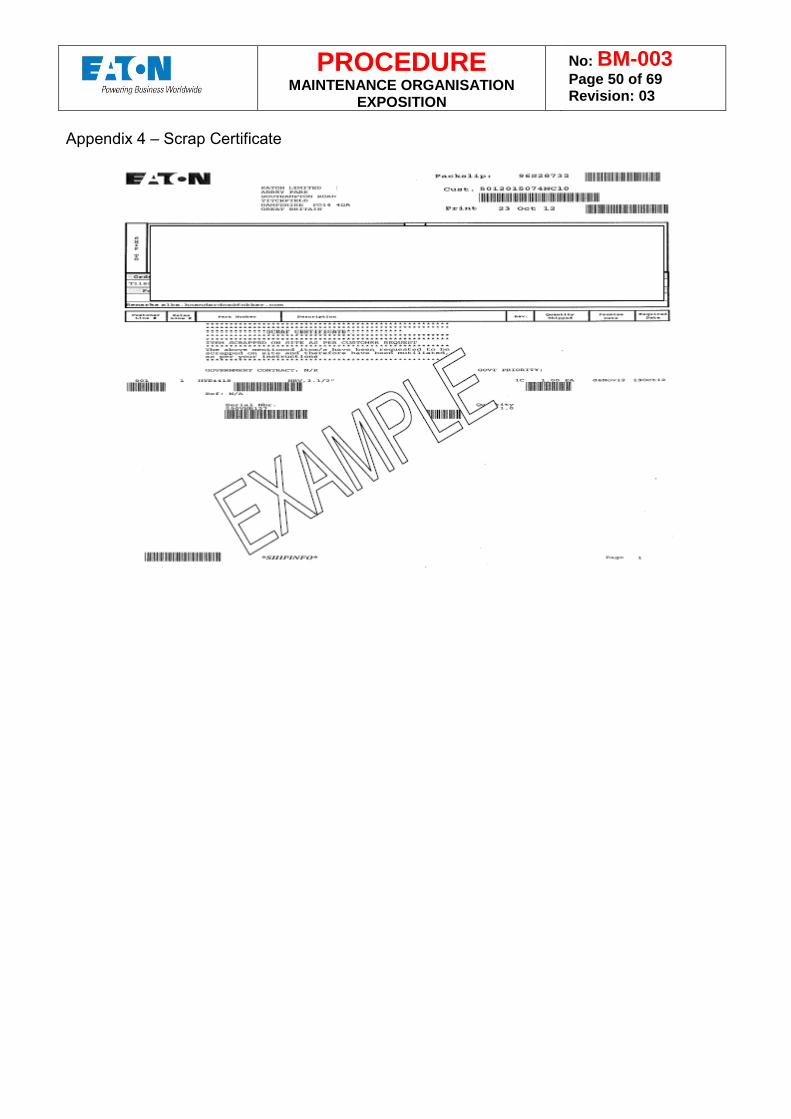
PROCEDURE MAINTENANCE ORGANISATION
EXPOSITION
No: BM-003 Page 50 of 69 Revision: 03
Appendix 4 – Scrap Certificate
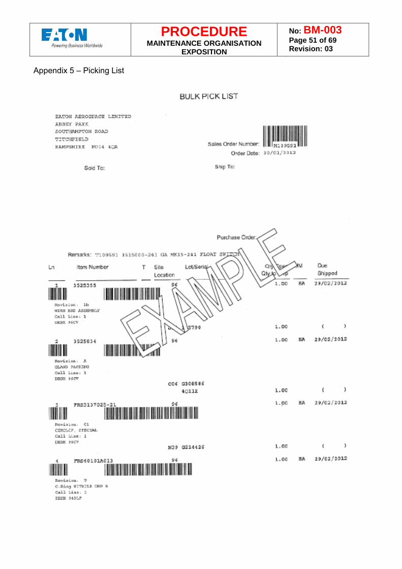
PROCEDURE MAINTENANCE ORGANISATION
EXPOSITION
No: BM-003 Page 51 of 69 Revision: 03
Appendix 5 – Picking List
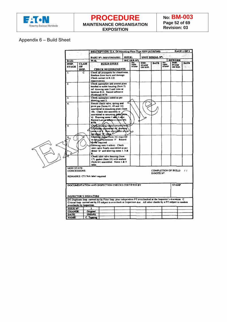
PROCEDURE MAINTENANCE ORGANISATION
EXPOSITION
No: BM-003 Page 52 of 69 Revision: 03
Appendix 6 – Build Sheet
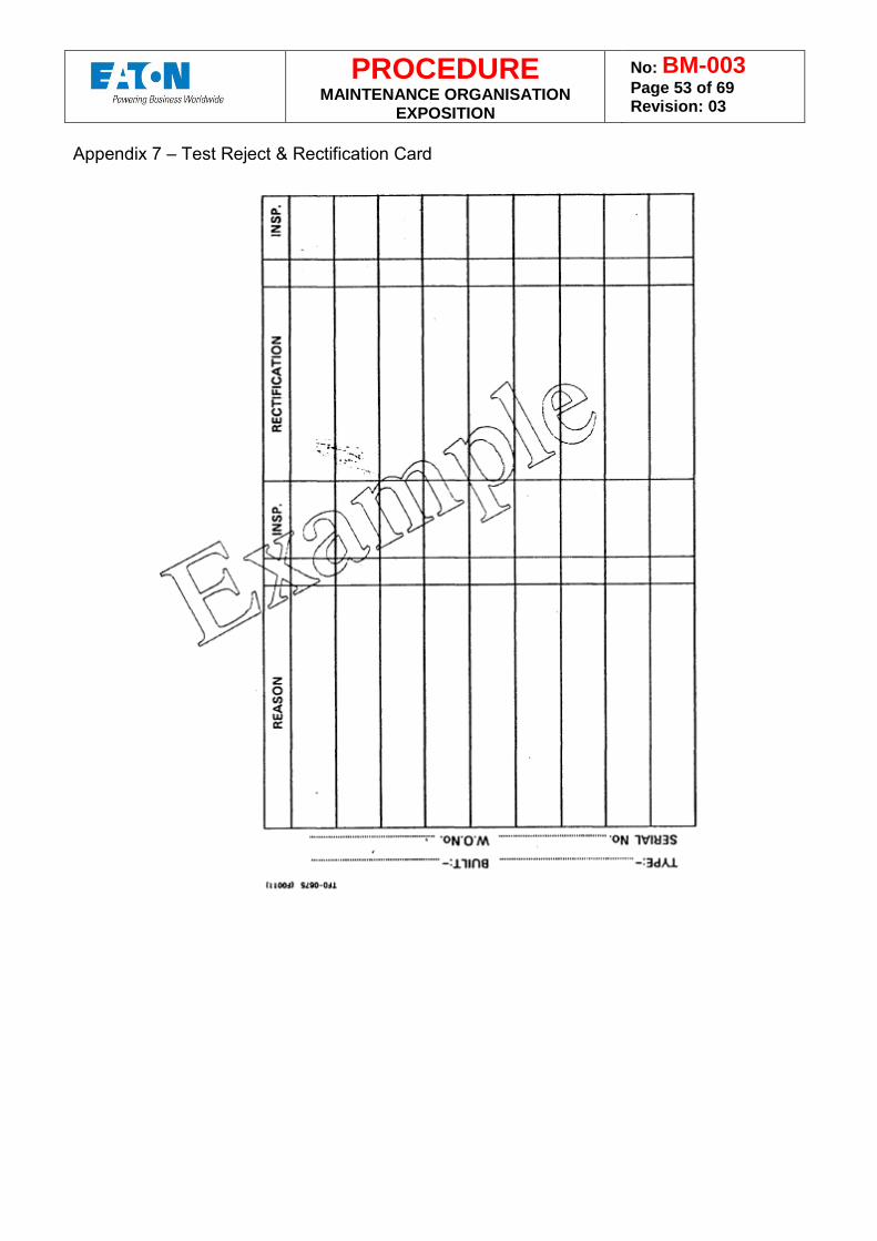
PROCEDURE MAINTENANCE ORGANISATION
EXPOSITION
No: BM-003 Page 53 of 69 Revision: 03
Appendix 7 – Test Reject & Rectification Card
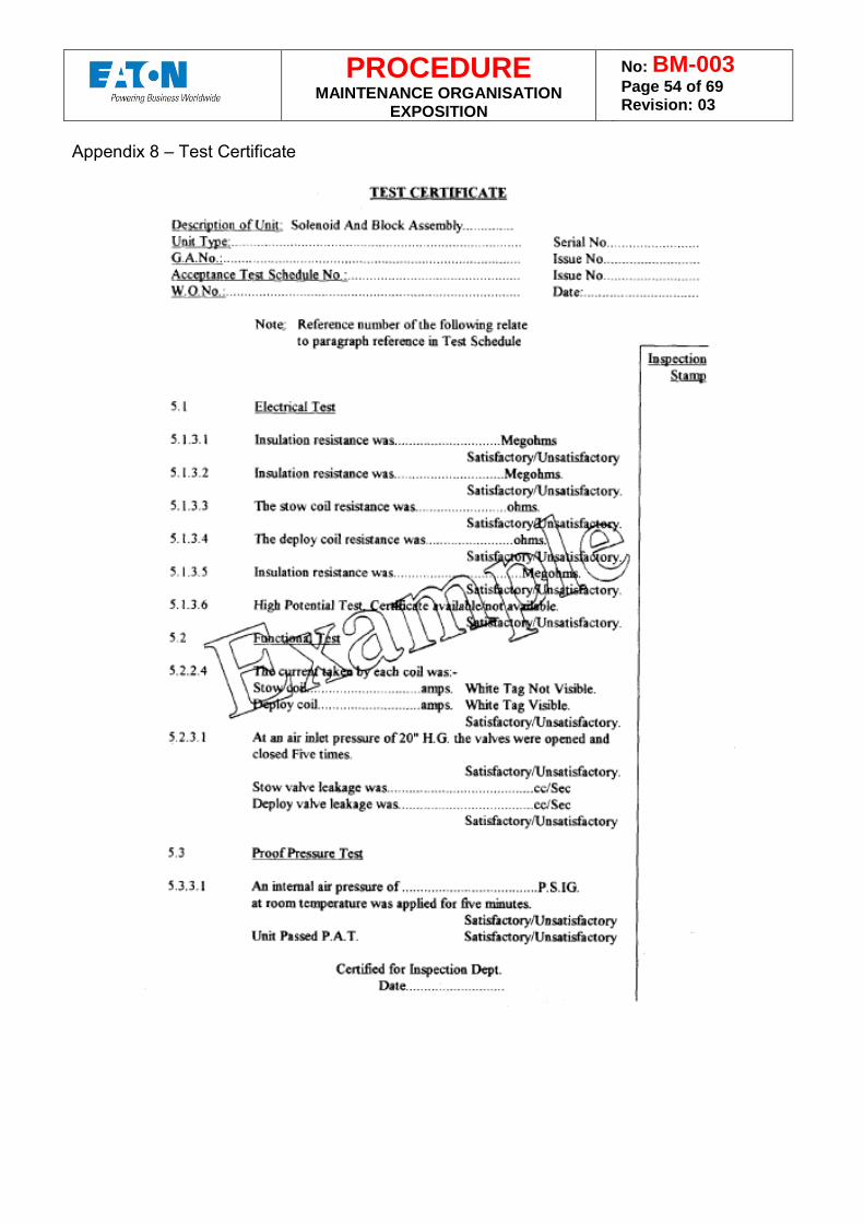
PROCEDURE MAINTENANCE ORGANISATION
EXPOSITION
No: BM-003 Page 54 of 69 Revision: 03
Appendix 8 – Test Certificate
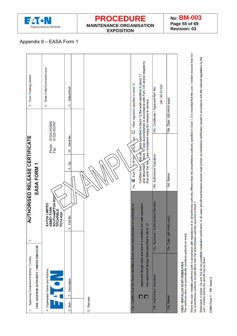
PROCEDURE MAINTENANCE ORGANISATION
EXPOSITION
No: BM-003 Page 55 of 69 Revision: 03
Appendix 9 – EASA Form 1
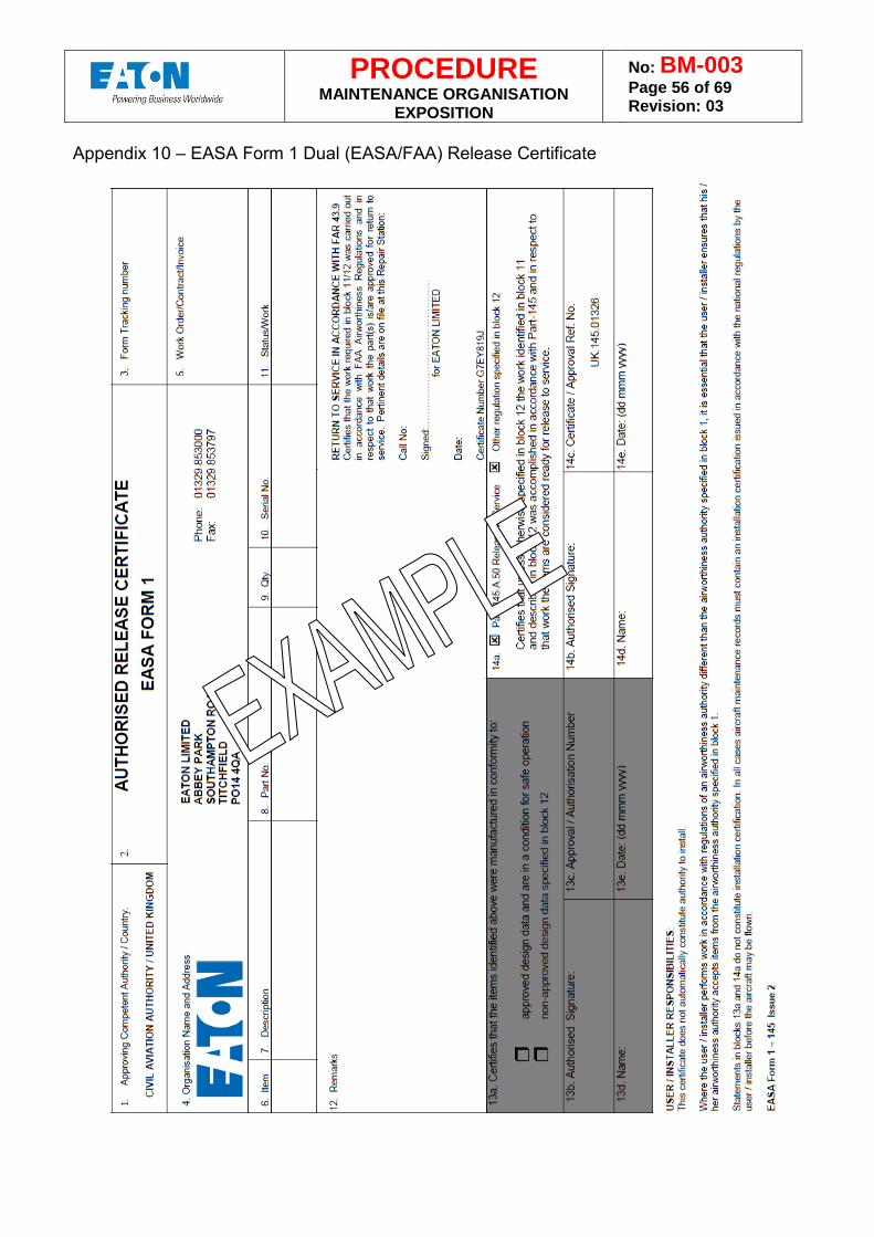
PROCEDURE MAINTENANCE ORGANISATION
EXPOSITION
No: BM-003 Page 56 of 69 Revision: 03
Appendix 10 – EASA Form 1 Dual (EASA/FAA) Release Certificate
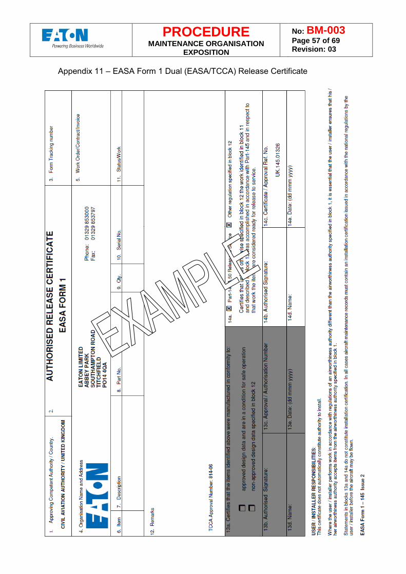
PROCEDURE MAINTENANCE ORGANISATION
EXPOSITION
No: BM-003 Page 57 of 69 Revision: 03
Appendix 11 – EASA Form 1 Dual (EASA/TCCA) Release Certificate
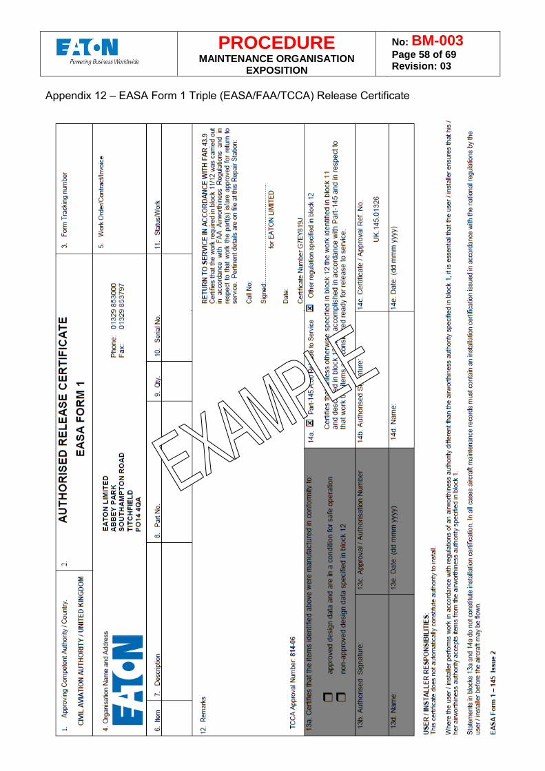
PROCEDURE MAINTENANCE ORGANISATION
EXPOSITION
No: BM-003 Page 58 of 69 Revision: 03
Appendix 12 – EASA Form 1 Triple (EASA/FAA/TCCA) Release Certificate
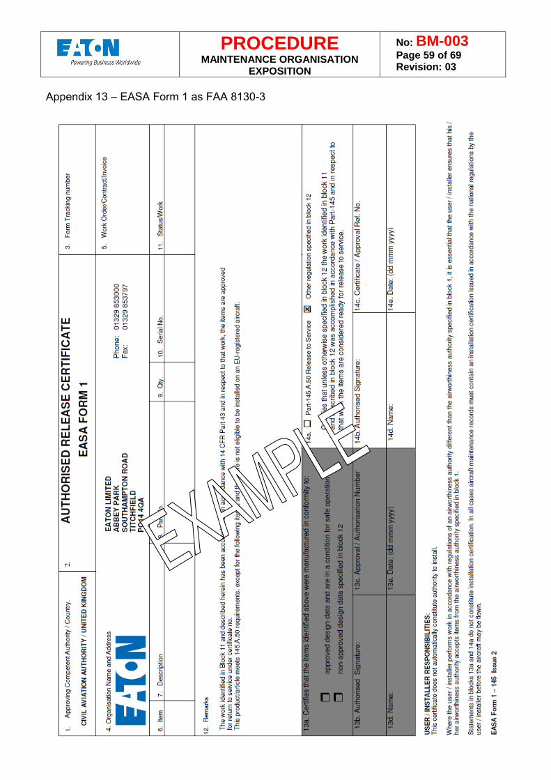
PROCEDURE MAINTENANCE ORGANISATION
EXPOSITION
No: BM-003 Page 59 of 69 Revision: 03
Appendix 13 – EASA Form 1 as FAA 8130-3
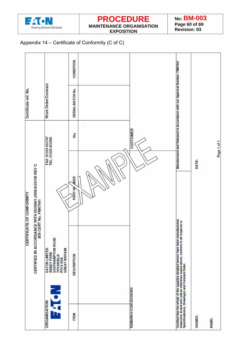
PROCEDURE MAINTENANCE ORGANISATION
EXPOSITION
No: BM-003 Page 60 of 69 Revision: 03
Appendix 14 – Certificate of Conformity (C of C)
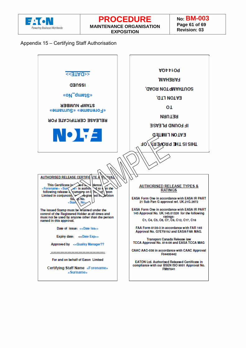
PROCEDURE MAINTENANCE ORGANISATION
EXPOSITION
No: BM-003 Page 61 of 69 Revision: 03
Appendix 15 – Certifying Staff Authorisation
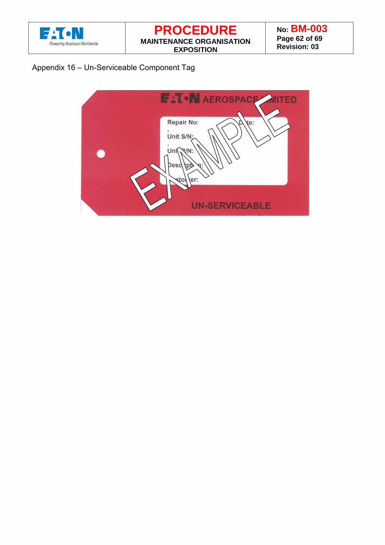
PROCEDURE MAINTENANCE ORGANISATION
EXPOSITION
No: BM-003 Page 62 of 69 Revision: 03
Appendix 16 – Un-Serviceable Component Tag
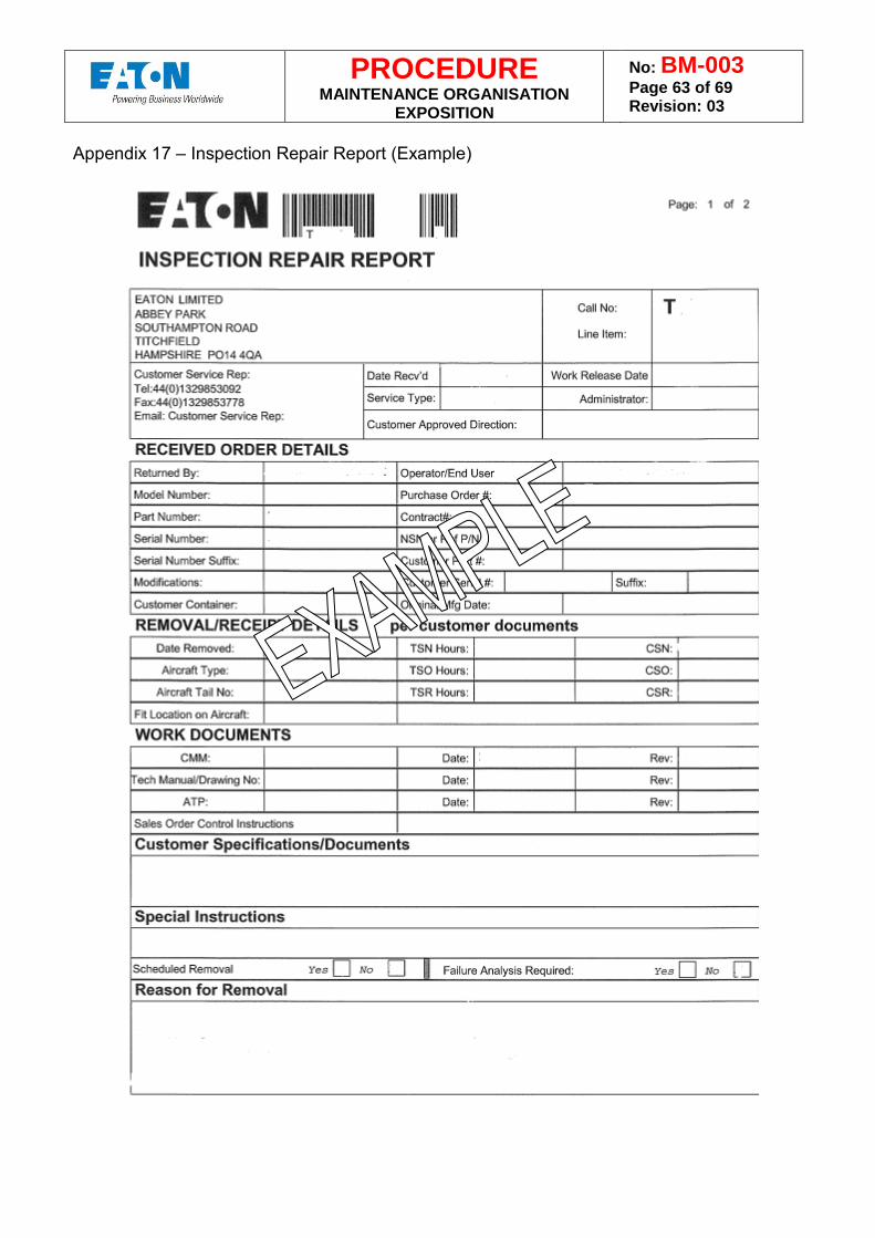
PROCEDURE MAINTENANCE ORGANISATION
EXPOSITION
No: BM-003 Page 63 of 69 Revision: 03
Appendix 17 – Inspection Repair Report (Example)
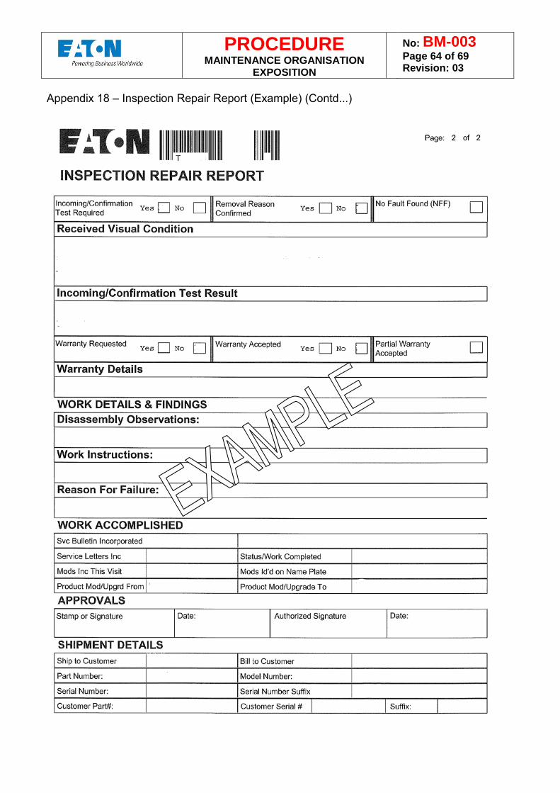
PROCEDURE MAINTENANCE ORGANISATION
EXPOSITION
No: BM-003 Page 64 of 69 Revision: 03
Appendix 18 – Inspection Repair Report (Example) (Contd...)
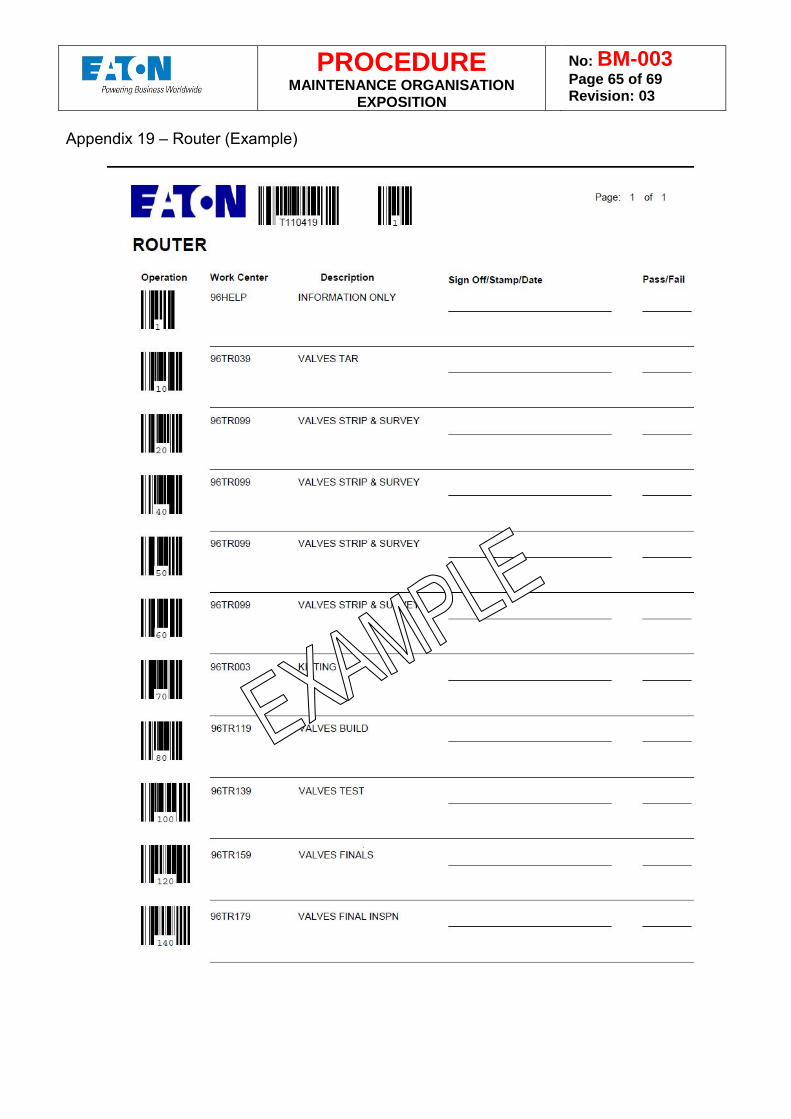
PROCEDURE MAINTENANCE ORGANISATION
EXPOSITION
No: BM-003 Page 65 of 69 Revision: 03
Appendix 19 – Router (Example)
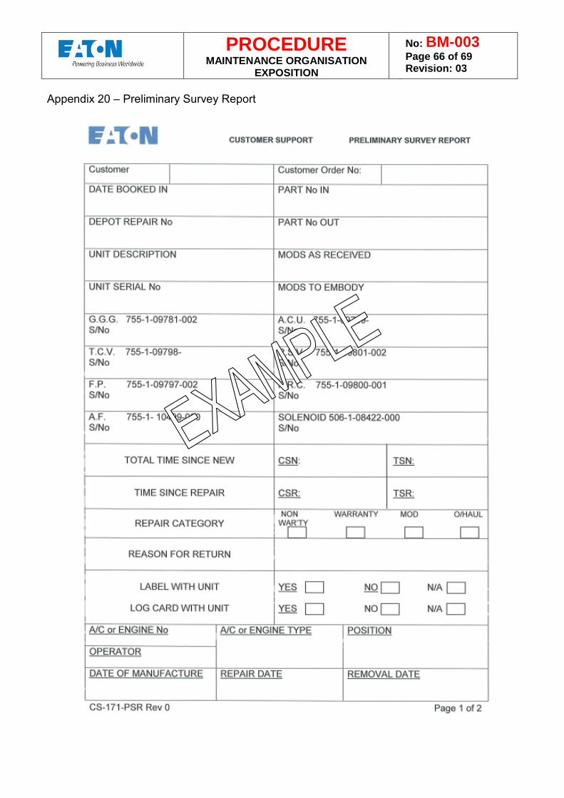
PROCEDURE MAINTENANCE ORGANISATION
EXPOSITION
No: BM-003 Page 66 of 69 Revision: 03
Appendix 20 – Preliminary Survey Report
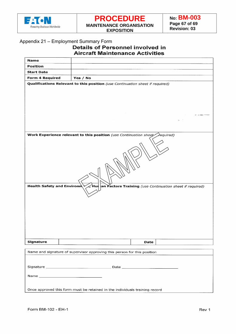
PROCEDURE MAINTENANCE ORGANISATION
EXPOSITION
No: BM-003 Page 67 of 69 Revision: 03
Appendix 21 – Employment Summary Form
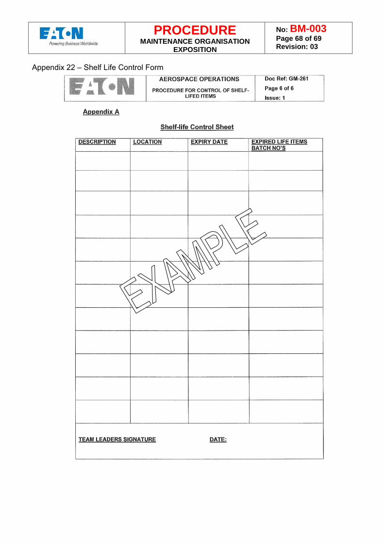
PROCEDURE MAINTENANCE ORGANISATION
EXPOSITION
No: BM-003 Page 68 of 69 Revision: 03
Appendix 22 – Shelf Life Control Form
PROCEDURE MAINTENANCE ORGANISATION
EXPOSITION
No: BM-003 Page 69 of 69 Revision: 03
PART 6 – Operators Maintenance Procedures Eaton Limited does not operate, store or maintain complete aircraft or major aircraft assemblies. This subject is therefore not applicable. PART 7 – FAA MAG SUPPLEMENT Refer to BM-WI-003-2 – FAA Supplement PART 8 – TCCA MAG SUPPLEMENT Refer to BM-WI-003-1 – TCCA Supplement


![SimulationEducation.pdf[2013-01-29] 2.27 MB](https://img.pdfslide.us/doc/110x75/5866c9ac1a28ab2c408b8c65/simulationeducationpdf2013-01-29-227-mb.jpg)
![[PowerPoint, (2.27 mb)]](https://img.pdfslide.us/doc/110x75/54646e2aaf795969338b493d/powerpoint-227-mb.jpg)