Embed Size (px)
Citation preview
Procedure for Calculating Building Chilled and
Hot Water Differential Pressure Setpoint
Rijin Sun
School of Environmental Science and Engineering
Suzhou University of Science and Technology
Suzhou, China E-mail: [email protected]
Chenggang Liu
School of Environmental Science and Engineering
Suzhou University of Science and Technology Suzhou, China
E-mail:[email protected]
*Corresponding author
Rundong Liu
School of Environmental Science and Engineering
Suzhou University of Science and Technology
Suzhou, China E-mail:[email protected]
Abstract—The calculation of the building differential
pressure (DP) setpoint based on the water flow-rate is
discussed in this paper. How to find the coefficient (k) of
water piping system in any case is the key in the calculation.
The condition of the building DP calculation is documented to make sure its correction. The theory of pump working
point matching water system curve is applied to find k in the
procedure. After adjusting the pressure drop on each air
handling unit and water balance for the system, the
measurement of the water flow-rate and the building DP can
be taken and system k can be calculated. Then, an example
of the building DP calculation is given.
Keywords-Pump Speed Control; Flow-rate; Differential Pressure Setpoint; VFD; Recommissioning
I. INTRODUCTION
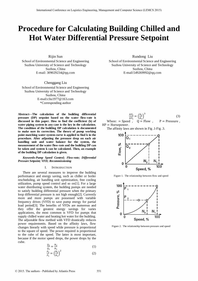
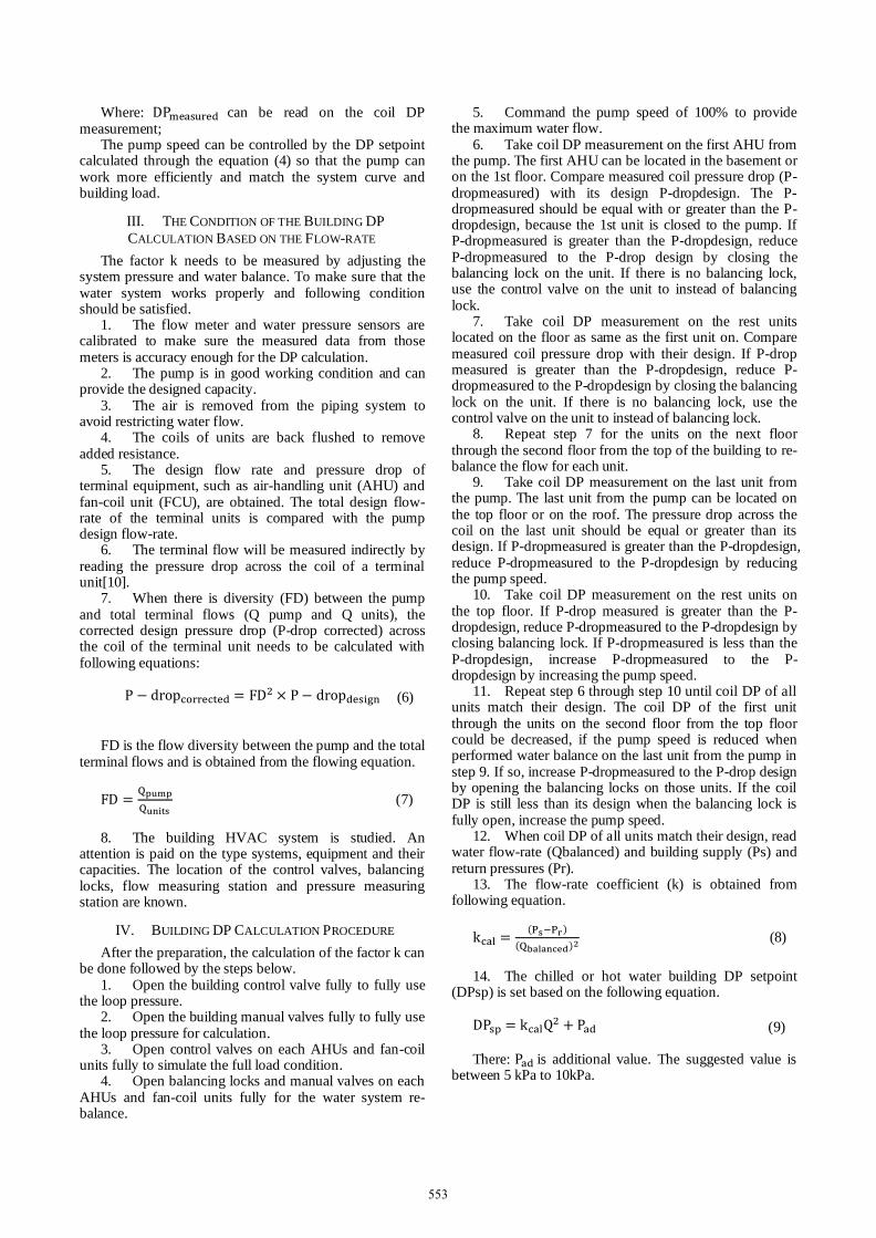
There are several measures to improve the building performance and energy saving, such as chiller or boiler rescheduling, air handling unit optimization, free cooling utilization, pump speed control and so on[1]. For a large water distributing system, the building pumps are needed to satisfy building differential pressure when the primary loop differential pressure is not high enough[2]. Currently more and more pumps are possessed with variable frequency drives (VFD) to save pump energy for partial load period[3]. The benefits of VFDs are numerous and they offer the greatest energy savings for varies applications, the most common is VFD for pumps that supply chilled water and heating hot water for the building. The adjustable flow method with VFD drastically reduces power requirements. Based on the affinity laws, flow changes linearly with speed while pressure is proportional to the square of speed. The power required is proportional to the cube of the speed. The latter is most important, because if the motor speed drops, the power drops by the cube.
(1)
(
) (2)
(
) (3)
Where: , , , .
The affinity laws are shown in Fig .1-Fig .3.
Figure 1. The relationship between flow and speed
Figure 2. The relationship between pressure and speed
International Conference on Logistics Engineering, Management and Computer Science (LEMCS 2015)
© 2015. The authors - Published by Atlantis Press 551
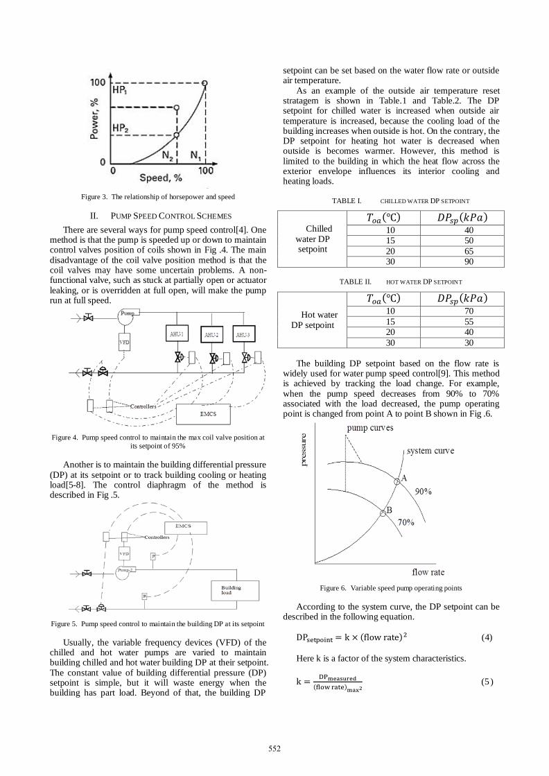
Figure 3. The relationship of horsepower and speed
II. PUMP SPEED CONTROL SCHEMES
There are several ways for pump speed control[4]. One method is that the pump is speeded up or down to maintain control valves position of coils shown in Fig .4. The main disadvantage of the coil valve position method is that the coil valves may have some uncertain problems. A non-functional valve, such as stuck at partially open or actuator leaking, or is overridden at full open, will make the pump run at full speed.
Figure 4. Pump speed control to maintain the max coil valve position at
its setpoint of 95%
Another is to maintain the building differential pressure (DP) at its setpoint or to track building cooling or heating load[5-8]. The control diaphragm of the method is described in Fig .5.
Figure 5. Pump speed control to maintain the building DP at its setpoint
Usually, the variable frequency devices (VFD) of the chilled and hot water pumps are varied to maintain building chilled and hot water building DP at their setpoint. The constant value of building differential pressure (DP) setpoint is simple, but it will waste energy when the building has part load. Beyond of that, the building DP
setpoint can be set based on the water flow rate or outside air temperature.
As an example of the outside air temperature reset stratagem is shown in Table.1 and Table.2. The DP setpoint for chilled water is increased when outside air temperature is increased, because the cooling load of the building increases when outside is hot. On the contrary, the DP setpoint for heating hot water is decreased when outside is becomes warmer. However, this method is limited to the building in which the heat flow across the exterior envelope influences its interior cooling and heating loads.
TABLE I. CHILLED WATER DP SETPOINT
Chilled water DP setpoint
( ) ( ) 10 40 15 50
20 65 30 90
TABLE II. HOT WATER DP SETPOINT
Hot water DP setpoint
( ) ( ) 10 70
15 55 20 40
30 30
The building DP setpoint based on the flow rate is widely used for water pump speed control[9]. This method is achieved by tracking the load change. For example, when the pump speed decreases from 90% to 70% associated with the load decreased, the pump operating point is changed from point A to point B shown in Fig .6.
Figure 6. Variable speed pump operating points
According to the system curve, the DP setpoint can be described in the following equation.
( ) (4)
Here k is a factor of the system characteristics.
( ) (5 )
552
Where: can be read on the coil DP measurement;
The pump speed can be controlled by the DP setpoint calculated through the equation (4) so that the pump can work more efficiently and match the system curve and building load.
III. THE CONDITION OF THE BUILDING DP
CALCULATION BASED ON THE FLOW-RATE
The factor k needs to be measured by adjusting the system pressure and water balance. To make sure that the water system works properly and following condition should be satisfied.
1. The flow meter and water pressure sensors are calibrated to make sure the measured data from those meters is accuracy enough for the DP calculation.
2. The pump is in good working condition and can provide the designed capacity.
3. The air is removed from the piping system to avoid restricting water flow.
4. The coils of units are back flushed to remove added resistance.
5. The design flow rate and pressure drop of terminal equipment, such as air-handling unit (AHU) and fan-coil unit (FCU), are obtained. The total design flow-rate of the terminal units is compared with the pump design flow-rate.
6. The terminal flow will be measured indirectly by reading the pressure drop across the coil of a terminal unit[10].
7. When there is diversity (FD) between the pump and total terminal flows (Q pump and Q units), the corrected design pressure drop (P-drop corrected) across the coil of the terminal unit needs to be calculated with following equations:
(6)
FD is the flow diversity between the pump and the total
terminal flows and is obtained from the flowing equation.
(7)
8. The building HVAC system is studied. An
attention is paid on the type systems, equipment and their capacities. The location of the control valves, balancing locks, flow measuring station and pressure measuring station are known.
IV. BUILDING DP CALCULATION PROCEDURE
After the preparation, the calculation of the factor k can be done followed by the steps below.
1. Open the building control valve fully to fully use the loop pressure.
2. Open the building manual valves fully to fully use the loop pressure for calculation.
3. Open control valves on each AHUs and fan-coil units fully to simulate the full load condition.
4. Open balancing locks and manual valves on each AHUs and fan-coil units fully for the water system re-balance.
5. Command the pump speed of 100% to provide the maximum water flow.
6. Take coil DP measurement on the first AHU from the pump. The first AHU can be located in the basement or on the 1st floor. Compare measured coil pressure drop (P-dropmeasured) with its design P-dropdesign. The P-dropmeasured should be equal with or greater than the P-dropdesign, because the 1st unit is closed to the pump. If P-dropmeasured is greater than the P-dropdesign, reduce P-dropmeasured to the P-drop design by closing the balancing lock on the unit. If there is no balancing lock, use the control valve on the unit to instead of balancing lock.
7. Take coil DP measurement on the rest units located on the floor as same as the first unit on. Compare measured coil pressure drop with their design. If P-drop measured is greater than the P-dropdesign, reduce P-dropmeasured to the P-dropdesign by closing the balancing lock on the unit. If there is no balancing lock, use the control valve on the unit to instead of balancing lock.
8. Repeat step 7 for the units on the next floor through the second floor from the top of the building to re-balance the flow for each unit.
9. Take coil DP measurement on the last unit from the pump. The last unit from the pump can be located on the top floor or on the roof. The pressure drop across the coil on the last unit should be equal or greater than its design. If P-dropmeasured is greater than the P-dropdesign, reduce P-dropmeasured to the P-dropdesign by reducing the pump speed.
10. Take coil DP measurement on the rest units on the top floor. If P-drop measured is greater than the P-dropdesign, reduce P-dropmeasured to the P-dropdesign by closing balancing lock. If P-dropmeasured is less than the P-dropdesign, increase P-dropmeasured to the P-dropdesign by increasing the pump speed.
11. Repeat step 6 through step 10 until coil DP of all units match their design. The coil DP of the first unit through the units on the second floor from the top floor could be decreased, if the pump speed is reduced when performed water balance on the last unit from the pump in step 9. If so, increase P-dropmeasured to the P-drop design by opening the balancing locks on those units. If the coil DP is still less than its design when the balancing lock is fully open, increase the pump speed.
12. When coil DP of all units match their design, read water flow-rate (Qbalanced) and building supply (Ps) and return pressures (Pr).
13. The flow-rate coefficient (k) is obtained from following equation.
( )
( ) (8)
14. The chilled or hot water building DP setpoint
(DPsp) is set based on the following equation.
(9)
There: is additional value. The suggested value is
between 5 kPa to 10kPa.
553
V. AN EXAMPLE OF THE BUILDING DP CALCULATION
A. The water system
The selected building for DP calculation is an institutional building. There are total eight large AHUs plus one small FCU serving the building. Two of them are outside air handling unit which serve the fresh air to the rest AHUs. Six of eight AHUs have chilled water design flow-rate of 16.5 m3/h for each unit; other two AHUs have 41 m3/h for each unit. The pressure drop across the cooling coil for each unit is 40 kPa. The total design chilled water flow-rate of the system is 181 m3/h.
The chilled water is supplied from the central plant through the campus water loop. Two chilled water pumps located in the basement serve the chilled water of the building (Fig .7). One stands by to the other. The design flow-rate for each chilled water pump is 153 m3/h. Before recommissioning, the constant value of 120kPa was used to pump speed control.
Figure 7. Chilled water system diagram of the Institutional building
B. The DP Calculation
According to the equation (7), the diversity of chilled water flow rate, FD, is
So the corrected design pressure drop across cooling
coil, P-drop, is
When the condition of the DP calculation is satisfied,
the steps in the procedure for the calculation were taken. With the chilled water system balanced, 113.1 kPa building DP was measured with the chilled water flow rate of 137 m3/h.
The flow-rate coefficient (k) is obtained from following equation.
( )
( )
The calculated k factor kcal, is 0.006.
Pad of 10 kPa is selected in this example. The new equation of chilled water building minimum programming value of 28 kPa .
The relation above could make sure the DP setpoint by
the flow-rate. As an example, the DP setpoint reset by flow-rate is list
in the Table 3 below.
TABLE III. TABLE.3 THE DP SETPOINT RESET BY FLOW-RATE
The DP setpoint reset by flow-rate
(m3/h)
(kPa)
70 40 90 59
110 83
130 111 The optimized DP setpoint is much lower the constant
value of 120kPa before and the energy savings are significantly obtained from DP calculation.
VI. CONCLUSIONS
The building DP setpoint based on flow rate method is achieved by tracking the load change, and it is a better method for pump speed control and it saves more energy than the other methods.
The calculation procedure of the building DP setpoint is generated and an example of the calculation is given. In the example, the pump power saving is achieved by the calculated building DP setpoint based on the flow rate.
REFERENCES
[1] Zheng Binhui. “Application and research on the fuzzy control of variable frequency in central air-conditioning system and the
terminal room,” ZheJiang University, 2012.
[2] Wang Zirong, Zhou Chundong. “The analysis of variable frequency pump energy saving technology,” Heilongjiang Science
and Technology Information, 2013,07:2.
[3] Zhang Chengwei. “ Frequency control technology used in central
air conditioning system energy saving,” GuiZhou University, 2008.
[4] Huang Yiyun, Zhang Ling. “Discussions on characteristics of variable-speed pumps controlled by pressure difference,” Heating
Ventilating & Air Conditioning, 2006,04:75-78
[5] Yao Guoliang. “Discussion on energy consumption of variable
frequency pump in air conditioning systems,” Heating Ventilating & Air Conditioning, 2004,06:32-34.
[6] Zhou Guobing, Zhang Yufeng, Wang Yan. “Energy Consumption
Analysis of Speed-control Pump in Varied Flow Water Heating System,” Fluid Machinery, 2003,03:4-10.
[7] Wang Handong. “Research on Characteristics of Variable Frequency Chilled Water Pumps in Central Air-Conditioning
Systems-Part 1,” Refrigeration, 2003,02:15-20.
[8] Wang Handong. “Research on Characteristics of Variable Frequency Chilled Water Pumps in Central Air-Conditioning
Systems-Part 2:Simulation and Analysis,” Refrigeration, 2003,02:15-20.
[9] Deng Qi, Liu Xinmin. “Collision of different energy saving control technologies in air conditioning chilled water systems,” Heating
Ventilating & Air Conditioning, 2015,04:13-20+12.
[10] Zhang Zaipeng, Chen Yanhua, Fu Yongzheng. “Effect of pressure difference control on hydraulic stability of variable flow air
conditioning water systems,” Heating Ventilating & Air Conditioning, 2009,06:63-66.
554


![and chilled foods. We are changing the way we deliver hotVendors Team]/Box Liners Info.pdf · We are changing the way we deliver hot and chilled foods. City Pantry part of What are](https://img.pdfslide.us/doc/110x75/605b3c141eb56179d673152d/and-chilled-foods-we-are-changing-the-way-we-deliver-hot-vendors-teambox-liners.jpg)