Embed Size (px)
Citation preview

| NODIS Library | Program Formulation(7000s) | Search |
NASA
Procedural
Requirements
NPR 7123.1A Effective Date: March 26, 2007
Expiration Date: May 26, 2013
COMPLIANCE IS MANDATORY
NASA Systems Engineering Processes and Requirementsw/Change 1 (11/04/09)
Responsible Office: Office of the Chief Engineer
NASA Request for Requirement Waiver (NRW) to NPR 1400.1E, Paragraph 3.7.4.j. with Regards toNPR 7123.1A Revision B, NRW 1400-54
NASA Interim Directive (NID) NASA Systems Engineering Processes and Requirements, NID7123-69
Table of Contents
Change Log
Preface
P.1 Purpose P.2 Applicability and Scope P.3 Authority P.4 References P.5 Measurement/Verification P.6 Cancellation
Chapter 1. Introduction
1.1 Background 1.2 Framework for Systems Engineering Procedural Requirements 1.3 Systems Engineering Management Plan 1.4 Document Organization
Chapter 2. Institutional and Programmatic Requirements
2.1 Roles and Responsibilities 2.2 Implementation Architecture 2.3 Designated Governing Authority
NPR 7123.1A -- TOCVerify current version before use at:
http://nodis3.gsfc.nasa.gov/Page 1 of 202
NPR 7123.1A -- TOCVerify current version before use at:
http://nodis3.gsfc.nasa.gov/Page 1 of 202

Chapter 3. Requirements for Common Technical Processes
3.1 Introduction 3.2 Process Requirements
Chapter 4. NASA Oversight Activities on Contracted Projects
4.1 Introduction 4.2 Activities Prior to Contract Award 4.3 During Contract Performance 4.4 Contract Completion
Chapter 5. Systems Engineering Technical Reviews
5.1 Life Cycle 5.2 Technical Review Requirements 5.3 Minimum Required Set of Technical Reviews
Chapter 6. Systems Engineering Management Plan
6.1 Systems Engineering Management Plan Function 6.2 Roles and Responsibilities
Appendix A. Definitions
Appendix B. Acronyms
Appendix C. Practices for Common Technical Processes
C.1 System Design Processes
C.2 Product Realization Processes
C.3 Technical Management Processes
Appendix D. Systems Engineering Management Plan
D.1 Purpose and Use D.2 Terms Used D.3 SEMP Preparation D.4 SEMP Annotated Outline
Appendix E. Hierarchy of Related NASA Documents
Appendix F. Tailoring
NPR 7123.1A -- TOCVerify current version before use at:
http://nodis3.gsfc.nasa.gov/Page 2 of 202
NPR 7123.1A -- TOCVerify current version before use at:
http://nodis3.gsfc.nasa.gov/Page 2 of 202

Appendix G. Technical Review Entrance and Success Criteria
G.1 Program/System Requirements Review G.2 Program/System Definition Review G.3 Mission Concept Review G.4 System Requirements Review G.5 Mission Definition Review G.6 System Definition Review G.7 Preliminary Design Review G.8 Critical Design Review G.9 Production Readiness Review G.10 System Integration Review G.11 Test Readiness Review G.12 System Acceptance Review G.13 Operational Readiness Review G.14 Flight Readiness Review G.15 Post-Launch Assessment Review G.16 Critical Event Readiness Review G.17 Post-Flight Assessment Review G.18 Decommissioning Review G.19 Periodic Technical Review G.20 Technical Peer Reviews
Appendix H. Templates
H-1 Sample SE NPR Implementation Plan Template H-2 SE NPR Center Survey
Appendix I. Additional Reading
Table of Figures
Figure 1-1 - SE Framework Figure 2-1 - Implementation Architecture Figure 3-1 - SE Engine Figure 3-2 - Application of SE Engine Processes within System Structure Figure 5-1 - The NASA Program Life Cycle Figure 5-2 - The NASA Project Life Cycle Figure 5-3 - Product Line Technical Review Schedule Figure A-1 - Product-Based WBS Model Example Figure C-1 - Stakeholder Expectation Definition Process Figure C-2 - Technical Requirements Definition Process Figure C-3 - Logical Decomposition Process Figure C-4 - Design Solution Definition Process Figure C-5 -Sequencing of Product Realization Processes Figure C-6 - Product Implementation Process Figure C-7 - Product Integration Process Figure C-8 - Product Verification Process Figure C-9 - Product Validation Process Figure C-10 - Product Transition Process
NPR 7123.1A -- TOCVerify current version before use at:
http://nodis3.gsfc.nasa.gov/Page 3 of 202
NPR 7123.1A -- TOCVerify current version before use at:
http://nodis3.gsfc.nasa.gov/Page 3 of 202

Figure C-11 - Technical Planning Process Figure C-12 - Requirements Management Process Figure C-13 - Interface Management Process Figure C-14 - Technical Risk Management Process Figure C-15 - Configuration Management Process Figure C-16 - Technical Data Management Process Figure C-17 - Technical Assessment Process Figure C-18 - Decision Analysis Process
Table of Tables
Table G-1 - P/SRR Entrance and Success Criteria Table G-2 - PAR Entrance and Success Criteria Table G-3 - MCR Entrance and Success Criteria Table G-4 - SRR Entrance and Success Criteria Table G-5 - MDR Entrance and Success Criteria Table G-6 - SDR Entrance and Success Criteria Table G-7 - PDR Entrance and Success Criteria Table G-8 - CDR Entrance and Success Criteria Table G-9 - PRR Entrance and Success Criteria Table G-10 - SIR Entrance and Success Criteria Table G-11 - TRR Entrance and Success Criteria Table G-12 - SAR Entrance and Success Criteria Table G-13 - ORR Entrance and Success Criteria Table G-14 - FRR Entrance and Success Criteria Table G-15 - PLAR Entrance and Success Criteria Table G-16 - CERR Entrance and Success Criteria Table G-17 - PFAR Entrance and Success Criteria Table G-18 - DR Entrance and Success Criteria Table G-19 - Technology Readiness Levels
NPR 7123.1A -- TOCVerify current version before use at:
http://nodis3.gsfc.nasa.gov/Page 4 of 202
NPR 7123.1A -- TOCVerify current version before use at:
http://nodis3.gsfc.nasa.gov/Page 4 of 202

Change History NPR 7123.1A, NASA Systems Engineering Processes and Requirements w/Change 1
(11/04/2009)
Change
Number
Date Change Description
1 11/04/2009 Administrative corrections made to provide clarification, revise definitions,
add criteria to consider personnel shifts when programs and projects end, and
update acronyms.
NPR 7123.1A -- ChangeLogVerify Current version before use at:
http://nodis3.gsfc.nasa.gov/Page 5 of 202
NPR 7123.1A -- ChangeLogVerify Current version befor use at:
http://nodis3.gsfc.nasa.gov/Page 5 of 202

Preface
P.1 Purpose
The purpose of this document is to clearly articulate and establish the requirements on theimplementing organization for performing, supporting, and evaluating systems engineering. Systemsengineering is a logical systems approach performed by multidisciplinary teams to engineer andintegrate NASA's systems to ensure NASA products meet customers' needs. Implementation of thissystems approach will enhance NASA's core engineering, management, and scientific capabilitiesand processes to ensure safety and mission success, increase performance, and reduce cost. Thissystems approach is applied to all elements of a system and all hierarchical levels of a system overthe complete project life cycle.
P.2 Applicability and Scope
a. This NASA Procedural Requirement (NPR) applies to NASA Headquarters and NASA Centers,including component facilities and technical and service support centers. It also applies to the JetPropulsion Laboratory to the extent specified in its contracts with NASA. This NPR applies toNASA employees and their service contractors that use NASA processes to augment and supportNASA technical work. NASA NPRs and this Systems Engineering NPR (SE NPR) do not apply toNASA contracts except as the NASA technical team flows down the systems engineeringresponsibilities to all members of the system team, including contractors and subcontractors. (SeeChapter 4.)
b. The scope of this document encompasses the common technical processes for large and smallprojects and activities in flight systems and ground support (FS&GS) projects, advanced technologydevelopment (ATD) projects with deliverables to FS&GS projects, information systems andtechnology projects, and institutional projects (IP). Application of this NPR to Construction ofFacilities (CoF) and Environmental Compliance and Restoration (ECR) projects (or portions thereof)should be scaled in accordance with the level of systems engineering for the function of the structureand documented in the systems engineering management plan (SEMP) (as required). In this sense,the design of facilities (or parts of facilities) for processing FS&GS activities would requireappropriate application of systems engineering effort, ensuring that interfaces with and functionalrequirements of the FS&GS systems engineering are addressed. The design of administrativefacilities or soil remediation projects may not require the application of specific systems engineeringefforts. Engineering requirements for CoF and ECR projects are specified in NPR 8820.2 and NPR8590.1, respectively. Applying the common technical processes and reviews may also benefit basicand applied research (BAR) and other ATD projects. They are recommended but not required forBAR and ATD projects.
c. In this document, the word "project" generally refers to a unit of work performed in programs,projects, and activities. Management of a work unit is referred to as "project management," whichincludes managing programs, projects, and activities. A project is : (1) A specific investment havingdefined goals, objectives, requirements, life-cycle cost, a beginning, and an end. A project yields
NPR 7123.1A -- PrefaceVerify Current version before use at:
http://nodis3.gsfc.nasa.gov/Page 6 of 202
NPR 7123.1A -- PrefaceVerify Current version befor use at:
http://nodis3.gsfc.nasa.gov/Page 6 of 202
new or revised products or services that directly address NASA's strategic needs. Projects may beperformed wholly in-house; by Government, industry, academia partnerships; or through contractswith private industry. (2) A unit of work performed in programs, projects, and activities.Requirements for technical work on projects, therefore, also apply to technical work performed onprograms.
d. The requirements enumerated in this document are applicable to all new programs and projects, aswell as to all programs and projects currently in Formulation phase as of the effective date of thisdocument. (See NPR 7120.5 for definitions of program phases.) This NPR also applies to programsand projects in their Implementation phase as of the effective date of this document. However, thetechnical team may request permission from the designated governing authority to be allowed tocontinue without complying with all or sections of this NPR.
e. Many other discipline areas such as safety, medical, reliability, maintainability, quality assurance,information technology, security, logistics, environmental, etc., perform functions during projectlife-cycle phases that influence or are influenced by the engineering functions performed and need tobe fully integrated with the engineering functions. The description of these disciplines and theirrelationship to the overall management life cycle are defined in other NASA directives; for example,the safety, medical, reliability, maintainability, and quality assurance requirements are defined in the8700 series of directives.
P.3 Authority
a. 42 U.S.C. 2473(c)(1), Section 203(c)(1), National Aeronautics and Space Act of 1958, asamended.
b. NPD 1000.0, Strategic Management & Governance Handbook.
c. NPD 1001.0, 2006 NASA Strategic Plan
d. NPD 1000.3, The NASA Organization.
e. NPD 7120.4, Program/Project Management.
P.4 References
a. The NPD 8700, NASA Safety and Mission Assurance (S&MA) and Success policy series.
b. NPR 7120.5, NASA Space Flight Program and Project Management Requirements.
c. NPD 2820.1, NASA Software Policy.
d. NPR 7150.2, NASA Software Engineering Requirements.
e. NPR 8000.4, Risk Management Procedural Requirements.
f. SP-6105, NASA Systems Engineering Handbook.
g. NPD 1080.1 NASA Science Policy.
h. NPR 1080.1 NASA Science Management.
NPR 7123.1A -- PrefaceVerify Current version before use at:
http://nodis3.gsfc.nasa.gov/Page 7 of 202
NPR 7123.1A -- PrefaceVerify Current version befor use at:
http://nodis3.gsfc.nasa.gov/Page 7 of 202

i. NPR 8820.2 Facility Project Implementation Guide.
j. NPD 1440.6, NASA Records Management.
k. NPR 1441.1, NASA Records Retention Schedules.
l. NPR 1800.1, NASA Occupational Health Program Procedures.
P.5 Measurement/Verification
Compliance with this NPR will be documented by Center Directors in the SE NPR ImplementationPlan, which reports how the particular Center will assess compliance to the SE NPR. In addition, theOffice of the Chief Engineer (OCE) conducts periodic assessments at the Centers to obtain feedbackon the effectiveness of the SE NPR to facilitate updating the NPR.
P.6 Cancellation
NPR 7123.1, NASA Systems Engineering Processes and Requirements, dated March 13, 2006, iscancelled on the effective date of NPR 7123.1A.
/S/
Christopher J. Scolese
Chief Engineer
DISTRIBUTION:
NODIS
NPR 7123.1A -- PrefaceVerify Current version before use at:
http://nodis3.gsfc.nasa.gov/Page 8 of 202
NPR 7123.1A -- PrefaceVerify Current version befor use at:
http://nodis3.gsfc.nasa.gov/Page 8 of 202

Chapter 1. Introduction
1.1 Background
1.1.1
Systems engineering at NASA requires the application of a systematic, disciplined engineeringapproach that is quantifiable, recursive, iterative, and repeatable for the development, operation,maintenance, and disposal of systems integrated into a whole throughout the life cycle of a project orprogram. The emphasis of systems engineering is on safely achieving stakeholder functional,physical, and operational performance requirements in the intended use environments over thesystem's planned life within cost and schedule constraints.
1.1.2
This NPR establishes a core set of common Agency-level technical processes and requirementsneeded to define, develop, realize, and integrate the quality of the system products created andacquired by or for NASA. The processes described in this document build upon and apply bestpractices and lessons learned from NASA, other governmental agencies, and industry to clearlydelineate a successful model to complete comprehensive technical work, reduce program andtechnical risk, and improve mission success. The set of common processes in this NPR may besupplemented and tailored to achieve specific project requirements. (See Appendix F. Tailoring.)
1.1.3
Under the lean governance of the updated NPD 1000.0, the relationship of the program/projectmanagement and the technical team was clarified to reflect new technical authority. Theprogram/project manager (PM) has overall responsibility for their program/project. The technicalteam works with and for the PM to accomplish the goals of the project. Due to this updatedgovernance, there is a need to clearly define the role of the systems engineering management plan(SEMP) and how it will be developed. The technical team, working under the overall programmanagement plan (PMP), develops and updates the SEMP as necessary. The technical team workswith the PM to review the content and obtain concurrence. This allows for thorough discussion andcoordination of how the proposed technical activities would impact the programmatic, cost, andschedule aspects of the project. However, in cases of pure technical issues and for approval ofrequested waivers to technical requirements, the technical team also has an independent routethrough the technical designated governing authority (DGA) (as described in Section 2.3) to resolveissues with program/project management. Once all issues are resolved, the PM signs the SEMP. Itthen goes to the DGA for final signature. The DGA signature assures that an independent review hasevaluated the technical aspects of the technical plans and allows for approval of technical waivers ortailoring of the requirements of this NPR and other relevant technical standards that pertain to thisNPR.
1.1.4 Precedence
The order of precedence in case of conflict between requirements is 42 U.S.C. 2473(c)(1), Section203(c)(1), National Aeronautics and Space Act of 1958, as amended; NPD 1000.0, StrategicManagement & Governance Handbook; NPD 1000.3, The NASA Organization; NPD 7120.4,
NPR 7123.1A -- Chapter1Verify Current version before use at:
http://nodis3.gsfc.nasa.gov/Page 9 of 202
NPR 7123.1A -- Chapter1Verify Current version befor use at:
http://nodis3.gsfc.nasa.gov/Page 9 of 202

Program/Project Management; and NPR 7123.1, NASA Systems Engineering Processes andRequirements.
1.1.5 Requirement Verbs
In this NPR, a requirement is identified by "shall," a good practice by "should," permission by "may"or "can," expected outcome or action by "will," and descriptive material by "is" or "are" (or anotherverb form of "to be").
1.1.6 Figures
Figures within this NPR are not intended to be prescriptive but notional.
1.2 Framework for Systems Engineering ProceduralRequirements
There are three major groupings of requirements within the Office of the Chief Engineer (OCE), i.e.,program management requirements, systems engineering requirements, and independent review.This NPR focuses on the systems engineering requirements. (See Appendix E for the hierarchy ofrelated documents.)
1.2.1 Systems Engineering Framework
1.2.1.1
The common systems engineering framework consists of three elements that make up NASAsystems engineering capability. The relationship of the three elements is illustrated in Figure 1-1.The integrated implementation of the three elements of the SE Framework is intended to improve theoverall capability required for the efficient and effective engineering of NASA systems. The SEprocesses are one element of the larger context to produce quality products and achieve missionsuccess. This NPR addresses the SE processes. The larger SE framework also includes the workforceand tools and methods. OCE initiatives to address these other elements include revision of theNASA handbook on systems engineering and development of tools and an assessment model.Together, these elements comprise the capability of an organization to perform successful SE. Eachelement is described below.
NPR 7123.1A -- Chapter1Verify Current version before use at:
http://nodis3.gsfc.nasa.gov/Page 10 of 202
NPR 7123.1A -- Chapter1Verify Current version befor use at:
http://nodis3.gsfc.nasa.gov/Page 10 of 202

Figure 1-1 SE Framework
1.2.1.2 Element 1: Common Technical Processes.
The common technical processes of this NPR provide what has to be done to engineer systemproducts within a project and why. These processes are applied to the hardware, software, andhuman parts of a system as one integrated whole. Within this NPR, the contribution of this elementto improvement of SE capability is made not only by the common set of technical processes but alsoby inclusion of:
a. Concepts and terminology that are basic to consistent application and communication of thecommon technical processes Agency-wide.
b. A structure for when the common technical processes are applied.
1.2.1.3 Element 2:Tools and Methods.
Tools and methods enable the efficient and effective completion of the activities and tasks of thecommon technical processes. An essential contribution of this element to SE capability is theimprovement of the engineering infrastructure through the three Agency-wide initiatives listedbelow.
a. Infusion of advanced methods and tools in the SE processes to achieve greater efficiency,collaboration, and communication among distributed teams.
b. Preparation of a NASA handbook on SE methodologies intended to provide a source for variousmethods and procedures that Centers can draw upon to plan implementation of the requiredprocesses in their projects. This will be an update of the current NASA Systems EngineeringHandbook (SP-6105) that will be aligned with NPR 7120.5 and the SE NPR.
c. Creation or adoption of an assessment model to measure the SE capability of projects withinNASA and to assess the improvements of capability resulting from implementation of the SE NPR,use of adopted methods and tools, and workforce engineering training.
1.2.1.4 Element 3:Workforce.
A well-trained, knowledgeable, and experienced technical workforce is essential for improving SEcapability. The workforce must be able to apply NASA and Center standardized methods and toolsfor the completion of the required SE processes within the context of the program or project to whichthey are assigned. In addition, they must be able to effectively communicate requirements and
NPR 7123.1A -- Chapter1Verify Current version before use at:
http://nodis3.gsfc.nasa.gov/Page 11 of 202
NPR 7123.1A -- Chapter1Verify Current version befor use at:
http://nodis3.gsfc.nasa.gov/Page 11 of 202

solutions to customers, other engineers, and management to work efficiently and effectively on ateam. Issues of recruitment, retention, and training are aspects included in this element. The OCEwill facilitate the training of the NASA workforce on the application of this and associated NPRs.
1.2.1.5 SE Capability.
Together, the three elements of Figure 1-1 comprise an Agency-wide capability to performsuccessful SE in the engineering of NASA system products.
1.3 Systems Engineering Management Plan
A Systems Engineering Management Plan (SEMP) is used to establish the technical content of theengineering work early in the Formulation phase for each project and updated throughout the projectlife cycle. The SEMP provides the specifics of the technical effort and describes what technicalprocesses will be used, how the processes will be applied using appropriate activities, how theproject will be organized to accomplish the activities, and the cost and schedule associated withaccomplishing the activities. The process activities are driven by the critical or key events during anyphase of a life cycle (including operations) that set the objectives and work product outputs of theprocesses and how the processes are integrated. (See Chapter 6 for a description of the SEMP andAppendix D for an annotated outline for the SEMP.) The SEMP provides the communication bridgebetween the project management team and the technical implementation teams and within technicalteams. The SEMP provides the framework to realize the appropriate work products that meet theentry and exit criteria of the applicable project life-cycle phases and provides management withnecessary information for making decisions.
1.4 Document Organization
This SE NPR is organized into the following chapters.
a. The Preface describes items such as the applicability, scope, authority, and references of this SENPR.
b. The Prologue describes the purpose and vision for this SE NPR.
c. Chapter 1 describes the SE framework and introduces the SEMP.
d. Chapter 2 describes the institutional and programmatic requirements, including roles andresponsibilities.
e. Chapter 3 describes the core set of common Agency-level technical processes and requirementsfor engineering NASA system products throughout the product life cycle. Appendix C containssupplemental amplifying material.
f. Chapter 4 describes the activities and requirements to be accomplished by assigned NASAtechnical teams or individuals (NASA employees and their service support contractors) whenperforming technical oversight of a prime or external contractor.
g. Chapter 5 describes the technical review requirements throughout the program and project lifecycles.
h. Chapter 6 describes the SEMP, including the SEMP role, functions, and content. Appendix Dprovides details of a generic SEMP annotated outline.
NPR 7123.1A -- Chapter1Verify Current version before use at:
http://nodis3.gsfc.nasa.gov/Page 12 of 202
NPR 7123.1A -- Chapter1Verify Current version befor use at:
http://nodis3.gsfc.nasa.gov/Page 12 of 202

NPR 7123.1A -- Chapter1Verify Current version before use at:
http://nodis3.gsfc.nasa.gov/Page 13 of 202
NPR 7123.1A -- Chapter1Verify Current version befor use at:
http://nodis3.gsfc.nasa.gov/Page 13 of 202

Chapter 2. Institutional and ProgrammaticRequirements
2.1 Roles and Responsibilities
2.1.1 General
2.1.1.1
The roles and responsibilities of senior management are defined in part in NPD 1000.0, StrategicManagement & Governance Handbook. NPR 7120.5, NASA Space Flight Program and ProjectManagement Requirements; NPD 7120.4, Program/Project Management; and other NASAdirectives define the responsibilities of program and project managers. This NPR establishes systemsengineering processes and responsibilities.
2.1.1.2
The OCE, under the authority of this SE NPR, shall ensure compliance with this SE NPR.
2.1.1.3
For programs and projects involving more than one Center, the lead organization shall developdocumentation to describe the hierarchy and reconciliation of Center plans implementing this NPR.The governing mission directorate determines whether a Center executes a project in a lead role or ina peer role. For Centers in peer roles, compliance should be jointly negotiated.
2.1.1.4
For systems that contain software, the technical team shall ensure that software developed withinNASA or acquired complies with NPD 2820.1, NASA Software Policy, and NPR 7150.2, NASASoftware Engineering Requirements. Note that NPR 7150.2 elaborates on the requirements in thisdocument and determines the applicability of requirements based on the Agency's softwareclassification. Also note that NPR 7150.2 contains additional Agency requirements for theacquisition, development, maintenance, and management of software.
2.1.1.5
The OCE shall be the clearinghouse for systems engineering policies to ensure compatibility acrossNASA. In the event of differences between program or project offices and the OCE staff, theconflict will ultimately reach the NASA Chief Engineer or mission director level. If agreement is notachieved at this level, the conflict will be brought to the NASA Administrator for resolution.
2.1.1.6
In this document, the phrase "the Center Directors shall..." means the roles and responsibilities of theCenter Directors may be further delegated within the organization as appropriate to the scope andscale of the system.
2.1.2 Center Directors
NPR 7123.1A -- Chapter2Verify Current version before use at:
http://nodis3.gsfc.nasa.gov/Page 14 of 202
NPR 7123.1A -- Chapter2Verify Current version befor use at:
http://nodis3.gsfc.nasa.gov/Page 14 of 202

2.1.2.1
Center Directors oversee and manage the infrastructure for the successful execution of technicalauthority, support, and assurance of all programs and projects.
2.1.2.2
Center Directors shall perform the following activities or delegate them to the appropriate Centerorganization:
a. Develop the SE NPR Implementation Plan per the template in Appendix H-1 describing how therequirements of this SE NPR will be applied to the programs and projects under their cognizance orauthority.
b. Establish policies, procedures, and processes to execute the requirements of this SE NPR.
c. Assess and take corrective actions to improve the execution of the requirements of this SE NPR.
d. Perform the SE NPR Center Survey in accordance with Appendix H-2 for the purpose ofproviding feedback on the SE NPR. The initial Center Survey will be submitted five months fromthe effective date of this SE NPR. Subsequent updates will be upon the request of the OCE, noearlier than nine months after the initial submission. The Center Survey will use the common surveytool in Appendix H-2 and will be submitted through the Center System Engineering Working Group(SEWG) representative.
e. Select appropriate standards applicable to projects under their control.
2.1.3 Technical Teams
Each technical team shall execute the Center processes intended to implement this SE NPR underthe oversight of the Center Directors in accordance with the SEMP. The makeup and organization ofeach technical team is the responsibility of each Center or program and includes the personnelrequired to implement the project.
2.2 Implementation Architecture
2.2.1 Implementation Plan
2.2.1.1
Figure 2-1 illustrates the engineering implementation flow and key documents. NPD 7120.4establishes the policy for engineering and program and project management for the Agency. Fromthat directive, the OCE developed and published this SE NPR, which is consistent andcomplementary to NPR 7120.5 and other pertinent Agency directives. The requirements establishedin this SE NPR will flow down to the implementing organizations and Centers.
2.2.1.2
The Center Directors shall submit their SE NPR Implementation Plan to the OCE within threemonths after the effective date of this NPR. The plan will be updated as required. The SE NPRImplementation Plan will be provided to mission directorates for review and comment. Each SENPR Implementation Plan will be approved by the OCE and include the applicable documentsemployed by the individual Centers. These Center documents may include Center proceduralrequirements, work instructions, standards, and rules, as well as other Center-unique documentation.
NPR 7123.1A -- Chapter2Verify Current version before use at:
http://nodis3.gsfc.nasa.gov/Page 15 of 202
NPR 7123.1A -- Chapter2Verify Current version befor use at:
http://nodis3.gsfc.nasa.gov/Page 15 of 202

The SE NPR is a requirements document that specifies what needs to be accomplished at an Agencylevel. There will also be a body of knowledge developed to assist in the implementation of the NPR.This body of knowledge will include an updated NASA Systems Engineering Handbook (SP-6105)as well as best practices, standards, and templates.
2.2.1.3
The Center Directors shall develop and document in the SE NPR Implementation Plan how theparticular Center will assess compliance to the SE NPR and provide regular updates to the OCE. Inaddition, the OCE will conduct periodic updates at the Centers to obtain feedback on theeffectiveness of the SE NPR to facilitate updating the NPR.
Figure 2-1 Implementation Architecture
2.3 Designated Governing Authority
The designated governing authority (DGA) for the technical effort in this SE NPR is the CenterDirector or the person or organization that has been designated by them to ensure the appropriatelevel of technical management oversight. The DGA is assigned primary responsibility for evaluatingthe technical content of a particular program or project to ensure that it is meeting the commitmentsspecified in the key management documents. Typically, the DGA is the final approval signature onthe Systems Engineering Management Plans, waiver authorizations, and other key technicaldocuments. While overall management of the project SEMPs, technical reviews, and similarproject-specific SE products and reviews is the responsibility of the program/project manager, whois expected to sign the documents, the DGA has the final approval signature to ensure independentassessment of technical content and waiver authorizations that pertain to this NPR.
NPR 7123.1A -- Chapter2Verify Current version before use at:
http://nodis3.gsfc.nasa.gov/Page 16 of 202
NPR 7123.1A -- Chapter2Verify Current version befor use at:
http://nodis3.gsfc.nasa.gov/Page 16 of 202

2.3.1 Tailoring and Waivers
2.3.1.1
The appropriate DGA shall have responsibility to approve or disapprove any SE NPR requirementthat is either tailored or waived. Approved tailoring or waivering will be documented in the SEMP,as per the directions provided in appendices D and F.
2.3.1.2
The amount of detail, formality, and rigor required for the implementation of this SE NPR'srequirements is tailorable based on the size and complexity of each project and acceptable risk,subject to approval by the project manager and the DGA. Critical project considerations (e.g., publicsafety, security, litigation exposures) may preclude tailoring out required process activities,regardless of cost, manpower available, or other considerations.
2.3.1.3
A waiver is a documented agreement intentionally releasing a program or project from meeting arequirement. Waivers are required to release a program or project from meeting a requirement in theexecution of the processes described in this SE NPR.
NPR 7123.1A -- Chapter2Verify Current version before use at:
http://nodis3.gsfc.nasa.gov/Page 17 of 202
NPR 7123.1A -- Chapter2Verify Current version befor use at:
http://nodis3.gsfc.nasa.gov/Page 17 of 202

Chapter 3. Requirements for CommonTechnical Processes
3.1 Introduction
3.1.1
This chapter establishes the core set of common technical processes and requirements to be used byNASA projects in engineering system products during applicable product-line life-cycle phases (seeFigure 5-3) to meet phase exit criteria and project objectives. The 17 common technical processesare enumerated according to their description in this chapter and their interactions shown in Figure3-1. This SE common technical processes model illustrates the use of: (1) the system designprocesses for "top down" design of each product in the system structure, (2) the product realizationprocesses for "bottom up" realization of each product in the system structure, and (3) the technicalmanagement processes for planning, assessing, and controlling the implementation of the systemdesign and product realization processes and to guide technical decisionmaking (decision analysis).The SE common technical processes model is referred to as an "SE engine" in this SE NPR to stressthat these common technical processes are used to drive the development of the system products andassociated work products required by management to satisfy the applicable product-line life-cyclephase exit criteria while meeting stakeholder expectations within cost, schedule, and risk constraints.
NPR 7123.1A -- Chapter3Verify Current version before use at:
http://nodis3.gsfc.nasa.gov/Page 18 of 202
NPR 7123.1A -- Chapter3Verify Current version befor use at:
http://nodis3.gsfc.nasa.gov/Page 18 of 202

Figure 31 SE Engine
3.1.2
The context in which the common technical processes are used is provided below.
3.1.2.1
The common technical processes are applied to a product-based Work Breakdown Structure (WBS)model to concurrently develop the products that will satisfy the operational or mission functions ofthe system (end products) and that will satisfy the life-cycle support functions of the system(enabling products). The enabling products facilitate the activities of system design, productrealization, operations and mission support, sustainment, and end-of-product-life disposal orrecycling by having the products and services available when needed.
3.1.2.2
The common technical processes are applied to design a system solution definition for each WBSmodel down and across each level of the system structure and to realize the WBS model endproducts up and across the system structure. Figure 3-2 illustrates how the three major sets ofprocesses of the SE Engine (system design processes, product realization processes, and technicalmanagement processes) are applied to a WBS model within a system structure (a hierarchy ofproduct-based WBS models).
NPR 7123.1A -- Chapter3Verify Current version before use at:
http://nodis3.gsfc.nasa.gov/Page 19 of 202
NPR 7123.1A -- Chapter3Verify Current version befor use at:
http://nodis3.gsfc.nasa.gov/Page 19 of 202

Figure 3-2 Application of SE Engine Processes within System Structure
3.1.2.3
The common technical processes are used to define the WBS models of the system structure in eachapplicable phase of the relevant product-line life cycle (see Figure 5-3) to generate work productsand system products needed to satisfy the exit criteria of the applicable phase. System engineeringcontinues well into the operations and maintenance phase of a project, i.e., after the system productsare delivered. For example, in the course of operating, maintaining, and disposing of an existingsystem, all upgrades, enhancements, supporting or enabling developments, and reconfigurationsmust apply the common SE technical processes.
3.1.2.4
The common technical processes are applied by assigned technical teams and individuals of theNASA workforce trained in the requirements of this SE NPR.
3.1.2.5
The assigned technical teams and individuals should use the appropriate and available sets of toolsand methods to accomplish required common technical process activities. This would include theuse of modeling and simulation as applicable to the product-line phase, location of the WBS modelin the system structure, and the applicable phase exit criteria.
3.1.3
The assigned technical teams shall define in the project SEMP how the required 17 commontechnical processes, as implemented by Center documentation, will be applied to the various levelsof project WBS model system structure during each applicable life-cycle phase and have theirapproach approved by the DGA.
3.2 Process Requirements
For the statements below "establish" means developing policy, work instructions, or procedures toimplement process activities. "Maintain" includes planning the process, providing resources,assigning responsibilities, training people, managing configurations, identifying and involvingstakeholders, and monitoring and controlling the process.
3.2.1 Stakeholder Expectations Definition Process
3.2.1.1
The Center Directors or designees shall establish and maintain a process to include activities,requirements, guidelines, and documentation, for the definition of stakeholder expectations for theapplicable WBS model.
3.2.1.2
The stakeholder expectations definition process is used to elicit and define use cases, scenarios,operational concepts, and stakeholder expectations for the applicable product-line life-cycle phasesand WBS model. This includes requirements for: (a) operational end products andlife-cycle-enabling products of the WBS model; (b) expected skills and capabilities of operators or
NPR 7123.1A -- Chapter3Verify Current version before use at:
http://nodis3.gsfc.nasa.gov/Page 20 of 202
NPR 7123.1A -- Chapter3Verify Current version befor use at:
http://nodis3.gsfc.nasa.gov/Page 20 of 202

life-cycle-enabling products of the WBS model; (b) expected skills and capabilities of operators orusers; (c) expected number of simultaneous users, (d) system and human performance criteria, (e)technical authority, standards, regulations, and laws; (f) factors such as safety, quality, security,context of use by humans, reliability, availability, maintainability, electromagnetic compatibility,interoperability, testability, transportability, supportability, usability, and disposability; and (g) localmanagement constraints on how work will be done (e.g., operating procedures). The baselinedstakeholder expectations are used for validation of the WBS model end product during productrealization.
3.2.1.3
Typical practices of this process are defined in Appendix C.1.1.
3.2.2 Technical Requirements Definition Process
3.2.2.1
The Center Directors or designees shall establish and maintain a process to include activities,requirements, guidelines, and documentation, for definition of the technical requirements from theset of agreed upon stakeholder expectations for the applicable WBS model.
3.2.2.2
The technical requirements definition process is used to transform the baselined stakeholderexpectations into unique, quantitative, and measurable technical requirements expressed as "shall"statements that can be used for defining a design solution for the WBS model end product andrelated enabling products.
3.2.2.3
Typical practices of this process are defined in Appendix C.1.2.
3.2.3 Logical Decomposition Process
3.2.3.1
The Center Directors or designees shall establish and maintain a process to include activities,requirements, guidelines, and documentation, for logical decomposition of the validated technicalrequirements of the applicable WBS model.
3.2.3.2
The logical decomposition process is used to improve understanding of the defined technicalrequirements and the relationships among the requirements (e.g., functional, behavioral, andtemporal) and to transform the defined set of technical requirements into a set of logicaldecomposition models and their associated set of derived technical requirements for input to thedesign solution definition process.
3.2.3.3
Typical practices of this process are defined in Appendix C.1.3.
3.2.4 Design Solution Definition Process
3.2.4.1
NPR 7123.1A -- Chapter3Verify Current version before use at:
http://nodis3.gsfc.nasa.gov/Page 21 of 202
NPR 7123.1A -- Chapter3Verify Current version befor use at:
http://nodis3.gsfc.nasa.gov/Page 21 of 202
3.2.4.1
The Center Directors or designees shall establish and maintain a process to include activities,requirements, guidelines, and documentation, for designing product solution definitions within theapplicable WBS model that satisfy the derived technical requirements.
3.2.4.2
The design solution definition process is used to translate the outputs of the logical decompositionprocess into a design solution definition that is in a form consistent with the product-line life-cyclephase and WBS model location in the system structure and that will satisfy phase exit criteria. Thisincludes transforming the defined logical decomposition models and their associated sets of derivedtechnical requirements into alternative solutions, then analyzing each alternative to be able to selecta preferred alternative, and fully defining that alternative into a final design solution definition thatwill satisfy the technical requirements. These design solution definitions will be used for generatingend products either by using the product implementation process or product integration process as afunction of the position of the WBS model in the system structure and whether there are additionalsubsystems of the end product that need to be defined. The output definitions from the designsolution (end product specifications) will be used for conducting product verification.
3.2.4.3
Typical practices of this process are defined in Appendix C.1.4.
3.2.5 Product Implementation Process
3.2.5.1
The Center Directors or designees shall establish and maintain a process to include activities,requirements, guidelines, and documentation, for implementation of a design solution definition bymaking, buying, or reusing an end product of the applicable WBS model.
3.2.5.2
The product implementation process is used to generate a specified product of a WBS modelthrough buying, making, or reusing in a form consistent with the product-line life-cycle phase exitcriteria and that satisfies the design solution definition specified requirements (e.g., drawings,specifications).
3.2.5.3
Typical practices of this process are defined in Appendix C.2.1
3.2.6 Product Integration Process
3.2.6.1
The Center Directors or designees shall establish and maintain a process to include activities,requirements, guidelines, and documentation for the integration of lower level products into an endproduct of the applicable WBS model in accordance with its design solution definition.
3.2.6.2
The product integration process is used to transform the design solution definition into the desiredend product of the WBS model through assembly and integration of lower level, validated end
NPR 7123.1A -- Chapter3Verify Current version before use at:
http://nodis3.gsfc.nasa.gov/Page 22 of 202
NPR 7123.1A -- Chapter3Verify Current version befor use at:
http://nodis3.gsfc.nasa.gov/Page 22 of 202

products in a form consistent with the product-line life-cycle phase exit criteria and that satisfies thedesign solution definition requirements (e.g., drawings, specifications).
3.2.6.3
Typical practices of this process are defined in Appendix C.2.2.
3.2.7 Product Verification Process
3.2.7.1
The Center Directors or designees shall establish and maintain a process to include activities,requirements, guidelines, and documentation, for verification of end products generated by theproduct implementation process or product integration process against their design solutiondefinitions.
3.2.7.2
The product verification process is used to demonstrate that an end product generated from productimplementation or product integration conforms to its design solution definition requirements as afunction of the product-line life-cycle phase and the location of the WBS model end product in thesystem structure. Special attention is given to demonstrating satisfaction of the measures ofperformance (MOPs) defined for each measure of effectiveness (MOEs) during conduct of thetechnical requirements definition process.
3.2.7.3
Typical practices of this process are defined in Appendix C.2.3.
3.2.8 Product Validation Process
3.2.8.1
The Center Directors or designees shall establish and maintain a process to include activities,requirements, guidelines, and documentation, for validation of end products generated by theproduct implementation process or product integration process against their stakeholderexpectations.
3.2.8.2
The product validation process is used to confirm that a verified end product generated by productimplementation or product integration fulfills (satisfies) its intended use when placed in its intendedenvironment and to ensure that any anomalies discovered during validation are appropriatelyresolved prior to delivery of the product (if validation is done by the supplier of the product) or priorto integration with other products into a higher-level assembled product (if validation is done by thereceiver of the product). The validation is done against the set of baselined stakeholder expectations.Special attention should be given to demonstrating satisfaction of the MOEs identified duringconduct of the stakeholder expectations definition process. The type of product validation is afunction of the form of the product and product-line life-cycle phase and in accordance with anapplicable customer agreement.
3.2.8.3
Typical practices of this process are defined in Appendix C.2.4.
NPR 7123.1A -- Chapter3Verify Current version before use at:
http://nodis3.gsfc.nasa.gov/Page 23 of 202
NPR 7123.1A -- Chapter3Verify Current version befor use at:
http://nodis3.gsfc.nasa.gov/Page 23 of 202

3.2.9 Product Transition Process
3.2.9.1
The Center Directors or designees shall establish and maintain a process to include activities,requirements, guidelines, and documentation, for transitioning end products to the next higher levelWBS-model customer or user.
3.2.9.2
The product transition process is used to transition a verified and validated end product that hasbeen generated by product implementation or product integration to the customer at the next level inthe system structure for integration into an end product or, for the top level end product, transitionedto the intended end user. The form of the product transitioned will be a function of the product-linelife-cycle phase exit criteria and the location within the system structure of the WBS model in whichthe end product exits.
3.2.9.3
Typical practices of this process are defined in Appendix C.2.5.
3.2.1 Technical Planning Process
3.2.10.1
The Center Directors or designees shall establish and maintain a process to include activities,requirements, guidelines, and documentation, for planning the technical effort.
3.2.10.2
The technical planning process is used to plan for the application and management of each commontechnical process and to identify, define, and plan the technical effort applicable to the product-linelife-cycle phase for WBS model location within the system structure and to meet project objectivesand product-line life-cycle phase exit criteria. A key document generated by this process is theSEMP. (See Chapter 6.)
3.2.10.3
Typical practices of this process are defined in Appendix C.3.1.
3.2.11 Requirements Management Process
3.2.11.1
The Center Directors or designees shall establish and maintain a process to include activities,requirements, guidelines, and documentation, for management of requirements defined andbaselined during the application of the system design processes.
3.2.11.2
The requirements management process is used to: (a) manage the product requirements identified,baselined, and used in the definition of the WBS model products during system design; (b) providebidirectional traceability back to the top WBS model requirements; and (c) manage the changes toestablished requirement baselines over the life cycle of the system products.
NPR 7123.1A -- Chapter3Verify Current version before use at:
http://nodis3.gsfc.nasa.gov/Page 24 of 202
NPR 7123.1A -- Chapter3Verify Current version befor use at:
http://nodis3.gsfc.nasa.gov/Page 24 of 202

3.2.11.3
Typical practices of this process are defined in Appendix C.3.2.
3.2.12 Interface Management Process
3.2.12.1
The Center Directors or designees shall establish and maintain a process to include activities,requirements, guidelines, and documentation, for management of the interfaces defined andgenerated during the application of the system design processes.
3.2.12.2
The interface management process is used to: (a) establish and use formal interface management toassist in controlling system product development efforts when the efforts are divided betweenGovernment programs, contractors, and/or geographically diverse technical teams within the sameprogram or project and (b) maintain interface definition and compliance among the end products andenabling products that compose the system, as well as with other systems with which the endproducts and enabling products must interoperate.
3.2.12.3
Typical practices of this process are defined in Appendix C.3.3.
3.2.13 Technical Risk Management Process
3.2.13.1
The Center Directors or designees shall establish and maintain a process to include activities,requirements, guidelines, and documentation, for management of the technical risk identified duringthe technical effort. (NPR 8000.4, Risk Management Procedural Requirements, is to be used as asource document for defining this process, and NPR 8705.5, Probabilistic Risk Assessment (PRA)Procedures for NASA Programs and Projects, provides one means of identifying and assessingtechnical risk.)
3.2.13.2
The technical risk management process is used to examine on a continuing basis the risks oftechnical deviations from the project plan and identify potential technical problems before theyoccur so that risk-handling activities can be planned and invoked as needed across the life of theproduct or project to mitigate impacts on achieving product-line life-cycle phase exit criteria andmeeting technical objectives.
3.2.13.3
Typical practices of this process are defined in Appendix C.3.4.
3.2.14 Configuration Management Process
3.2.14.1
The Center Directors or designees shall establish and maintain a process to include activities,requirements, guidelines, and documentation, for configuration management.
NPR 7123.1A -- Chapter3Verify Current version before use at:
http://nodis3.gsfc.nasa.gov/Page 25 of 202
NPR 7123.1A -- Chapter3Verify Current version befor use at:
http://nodis3.gsfc.nasa.gov/Page 25 of 202

3.2.14.2
The configuration management process for end products, enabling products, and other work productsplaced under configuration control is used to: (a) identify the configuration of the product or workproduct at various points in time; (b) systematically control changes to the configuration of theproduct or work product; (c) maintain the integrity and traceability of the configuration of theproduct or work product throughout its life; and (d) preserve the records of the product or endproduct configuration throughout its life cycle, dispositioning them in accordance with NPR 1441.1,NASA Records Retention Schedules.
3.2.14.3
Typical practices of this process are defined in Appendix C.3.5.
3.2.15 Technical Data Management Process
3.2.15.1
The Center Directors or designees shall establish and maintain a process to include activities,requirements, guidelines, and documentation, for management of the technical data generated andused in the technical effort.
3.2.15.2
The technical data management process is used to: (a) provide the basis for identifying andcontrolling data requirements; (b) responsively and economically acquire, access, and distribute dataneeded to develop, manage, operate, and support system products over their product-line life; (c)manage and disposition data as records; (d) analyze data use; (e) if any of the technical effort isperformed by an external contractor, obtain technical data feedback for managing the contractedtechnical effort; and (f) assess the collection of appropriate technical data and information.
3.2.15.3
Typical practices of this process are defined in Appendix C.3.6.
3.2.16 Technical Assessment Process
3.2.16.1
The Center Directors or designees shall establish and maintain a process to include activities,requirements, guidelines, and documentation, for making assessments of the progress of plannedtechnical effort and progress toward requirements satisfaction.
3.2.16.2
The technical assessment process is used to help monitor progress of the technical effort and providestatus information for support of the system design, product realization, and technical managementprocesses.
3.2.16.3
Typical practices of this process are defined in Appendix C.3.7.
3.2.17 Decision Analysis Process
NPR 7123.1A -- Chapter3Verify Current version before use at:
http://nodis3.gsfc.nasa.gov/Page 26 of 202
NPR 7123.1A -- Chapter3Verify Current version befor use at:
http://nodis3.gsfc.nasa.gov/Page 26 of 202
3.2.17.1
The Center Directors or designees shall establish and maintain a process to include activities,requirements, guidelines, and documentation, for making technical decisions.
3.2.17.2
The decision analysis process, including data collection (e.g., engineering performance, quality, andreliability data), is used to help evaluate technical decision issues, technical alternatives, and theiruncertainties to support decisionmaking. This process is used throughout technical management,system design, and product realization processes to evaluate the impact of decisions on performance,cost, schedule, and technical risk.
3.2.17.3
Typical practices of this process are defined in Appendix C.3.8.
NPR 7123.1A -- Chapter3Verify Current version before use at:
http://nodis3.gsfc.nasa.gov/Page 27 of 202
NPR 7123.1A -- Chapter3Verify Current version befor use at:
http://nodis3.gsfc.nasa.gov/Page 27 of 202

Chapter 4. NASA Oversight Activities onContracted Projects
4.1 Introduction
4.1.1
Oversight/insight of projects where prime or external contractors do the majority of the developmenteffort has always been an important part of NASA programs and projects. With the new focus onExploration and Space missions, not only will such projects increase, but also it will become morecritical that NASA provide increased systems engineering on these projects before, during, and aftercontract performance.
4.1.2
This chapter defines a minimum set of technical activities and requirements for a NASA projecttechnical team to perform before contract award, during contract performance, and upon completionof the contract on projects where prime or external contractors do the majority of the developmenteffort. These activities and requirements are intended to supplement the common technical processactivities and requirements of Chapter 3 and thus enhance the outcome of the contracted effort.
4.2 Activities Prior to Contract Award
4.2.1
The assigned NASA technical team shall prepare a SEMP that covers the periods before contractaward, during contract performance, and upon contract completion in accordance with contentcontained in the annotated outline in Appendix D.
4.2.2
The assigned technical team shall use common technical processes, as implemented by the Center'sdocumentation, to establish the technical inputs to the Request for Proposal (RFP) appropriate for theproduct to be developed, including product requirements and Statement of Work tasks.
4.2.3
The technical team shall determine the technical work products to be delivered by the offeror orcontractor, to include a contractor SEMP that specifies their systems engineering approach forrequirements development; technical solution definition; design realization; product evaluation;product transition; and technical planning, control, assessment, and decision analysis.
4.2.4
The technical team shall provide to the contracting officer, for inclusion in the RFP, therequirements for technical oversight activities planned in the NASA SEMP. (Care should be taken
NPR 7123.1A -- Chapter4Verify Current version before use at:
http://nodis3.gsfc.nasa.gov/Page 28 of 202
NPR 7123.1A -- Chapter4Verify Current version befor use at:
http://nodis3.gsfc.nasa.gov/Page 28 of 202

requirements for technical oversight activities planned in the NASA SEMP. (Care should be takenthat no requirements or solicitation information is divulged prior to the release of the solicitation bythe cognizant contracting officer.)
4.2.5
The technical team shall participate in the evaluation of offeror proposals following applicableNASA and Center source selection procedures.
4.3 During Contract Performance
4.3.1
The assigned technical team, under the authority of the cognizant contracting officer, shall performthe technical oversight activities established in the NASA SEMP.
4.4 Contract Completion
4.4.1
The assigned technical team shall participate in scheduled milestone reviews to finalize Governmentacceptance of the deliverables.
4.4.2
The assigned technical team shall participate in product transition to the customer and/or disposal asdefined in the NASA SEMP.
NPR 7123.1A -- Chapter4Verify Current version before use at:
http://nodis3.gsfc.nasa.gov/Page 29 of 202
NPR 7123.1A -- Chapter4Verify Current version befor use at:
http://nodis3.gsfc.nasa.gov/Page 29 of 202

Chapter 5. Systems Engineering TechnicalReviews
5.1 Life Cycle
5.1.1
NASA has four interrelated product lines: Basic and Applied Research (BAR); Advanced TechnologyDevelopment (ATD); Flight System and Ground Support (FS&GS) projects; and Institutional Projects (IPs).Each product line has its own unique product-line life cycle. Figure 5-1 shows the life cycle for NASAprograms. Figure 5-2 shows the life cycle for NASA projects. Figure 5-3 shows the product line technicalreview schedule and technical reviews mapped into the management life cycle.
5.1.2
The IP management life cycle proceeds through a capital assets life cycle in five well-defined phases. An IPproject starts with a "Pre-Formulation and Proposal" phase, progresses into a "Preliminary Design" and thena "Build/Construct/Fabricate" phase, and eventually ends after "Operations and Maintenance" with an "AssetDisposal" phase. For noncapital asset projects, the last three phases are replaced by an "Execute ProjectPlan" phase. Typically, these projects enable all of the other NASA investment areas and product lines.
5.1.3
The two major common phases for all product lines are Formulation and Implementation. Each product linehas specific phases. FS&GS projects have three variations human, robotic, and Announcement ofOpportunity (AO) projects.
5.1.4
The life-cycle phases and the technical reviews of this chapter are closely linked to the managementlife-cycle phases of NPR 7120.5 as represented in figures 5-1 and 5-2. The application of the commontechnical processes within each life-cycle phase produces technical results that provide inputs to technicalreviews and support informed management decisions for progressing to the next life-cycle phase.
5.1.5
The progress between life-cycle phases is marked by key decision points (KDPs). At each KDP,management examines the maturity of the technical aspects of the project. For example, managementexamines whether the resources (staffing and funding) are sufficient for the planned technical effort, whetherthe technical maturity has evolved, what the technical and nontechnical internal issues and risks are, orwhether the stakeholder expectations have changed. If the technical and management aspects of the projectare satisfactory, including the implementation of corrective actions, then the project can be approved toproceed to the next phase.
NPR 7123.1A -- Chapter5Verify Current version before use at:
http://nodis3.gsfc.nasa.gov/Page 30 of 202
NPR 7123.1A -- Chapter5Verify Current version befor use at:
http://nodis3.gsfc.nasa.gov/Page 30 of 202

Figure 5.1 The NASA Program Life Cycle
NPR 7123.1A -- Chapter5Verify Current version before use at:
http://nodis3.gsfc.nasa.gov/Page 31 of 202
NPR 7123.1A -- Chapter5Verify Current version befor use at:
http://nodis3.gsfc.nasa.gov/Page 31 of 202

Figure 5.2 The NASA Project Life Cycle
NPR 7123.1A -- Chapter5Verify Current version before use at:
http://nodis3.gsfc.nasa.gov/Page 32 of 202
NPR 7123.1A -- Chapter5Verify Current version befor use at:
http://nodis3.gsfc.nasa.gov/Page 32 of 202

Figure 5.3 Product Line Technical Review Schedule
5.1.6
Three points are important: (1) Management reviews and the technical reviews support one another. (2)Technical reviews are completed before a KDP. (3) Technical reviews are event based and occur when theentrance criteria for the applicable review as specified in Appendix G are satisfied. They occur based on thematurity of the relevant technical baseline as opposed to calendar milestones (e.g., the quarterly progressreview, the yearly summary).
NPR 7123.1A -- Chapter5Verify Current version before use at:
http://nodis3.gsfc.nasa.gov/Page 33 of 202
NPR 7123.1A -- Chapter5Verify Current version befor use at:
http://nodis3.gsfc.nasa.gov/Page 33 of 202

5.2 Technical Review Requirements
5.2.1 Review Process and Practices
5.2.1.1
For each product line (BAR, ATD, IP, and FS&GS), technical efforts are monitored throughout the life cycleto ensure that the technical goals of the project are being achieved and that the technical direction of theproject is appropriate.
5.2.1.2
Technical teams shall monitor technical effort through periodic technical reviews.
5.2.1.3
A technical review is an evaluation of the project, or element thereof, by a knowledgeable group for thepurposes of:
a. Assessing the status of and progress toward accomplishing the planned activities.
b. Validating the technical tradeoffs explored and design solutions proposed.
c. Identifying technical weaknesses or marginal design and potential problems (risks) and recommendingimprovements and corrective actions.
d. Making judgments on the activities' readiness for the follow-on events, including additional futureevaluation milestones to improve the likelihood of a successful outcome.
e. Making assessments and recommendations to the project team, Center, and Agency management.
f. Providing a historical record that can be referenced of decisions that were made during these formalreviews.
g. Assessing the technical risk status and current risk profile.
5.2.1.4
See NPR 7120.5 for major program and project reviews and independent reviews.
5.2.1.5
Technical reviews are used to evaluate the status of the technical progress and are supported by otherequivalent technical discipline activities, including safety reviews.
5.2.1.6
The technical team shall ensure that system aspects represented or implemented in software are included inall technical reviews to demonstrate that project technical goals and progress are being achieved and that allNPR 7150.2 software review requirements are implemented.
5.2.2 Planning and Conduct
The technical team shall develop and document plans for technical reviews for use in the project planningprocess. The technical review schedule, as documented in the SEMP, will be reflected in the overall projectplan described in NPR 7120.5. The results of each technical review will be used to update the technicalreview plan as part of the SEMP update process. The review plans, data, and results should be maintainedand dispositioned as Federal records .
NPR 7123.1A -- Chapter5Verify Current version before use at:
http://nodis3.gsfc.nasa.gov/Page 34 of 202
NPR 7123.1A -- Chapter5Verify Current version befor use at:
http://nodis3.gsfc.nasa.gov/Page 34 of 202

5.3 Minimum Required Set of Technical Reviews
5.3.1 Definition of Minimum Required Reviews
5.3.1.1
The minimum set of required technical reviews applies to all current and future NASA FS&GS and IPprograms and projects as defined in section P.2 of this document (including spacecraft, launch vehicles,instruments developed for space flight programs and projects, designated research and technologydevelopments to be incorporated by space flight programs and projects, critical technical facilitiesspecifically developed or significantly modified for space flight systems, information systems andtechnology that support space flight programs and projects, and ground systems that are in direct support ofspace flight operations). Between each life-cycle phase, a program or project goes through KDPs precededby one or more reviews that enable a disciplined approach to assessing programs' and projects' readiness toprogress to the next phase. Allowances are made within a phase for the differences between human androbotic FS&GS projects. Additional description of technical reviews is provided in the NASA SystemsEngineering Handbook (SP-6105). (For more information on program and project life cycles andmanagement reviews, see the appropriate NPR, e.g., NPR 7120.5.)
5.3.1.2
The technical team shall address the entrance and success criteria listed in Appendix G for applicability tothe respective reviews.
5.3.1.3
The technical team shall execute the required Program/System Requirements Review (P/SRR) and ProgramApproval Review (PAR) in accordance with the review entry and success criteria defined in tables G-1 andG-2 of Appendix G.
5.3.1.4
The technical team shall execute the required program technical reviews in accordance with the followingtimeline: P/SRR before KDP 0 and PAR before KDP 1.
5.3.1.5
For human FS&GS projects, the technical team shall execute the following required minimum set oftechnical reviews in accordance with the review entry and success criteria defined in tables G-3, G-4, G-6,G-7, G-8, and G-10 through G-18 of Appendix G: Mission Concept Review (MCR), System RequirementsReview (SRR), System Definition Review (SDR), Preliminary Design Review (PDR), Critical DesignReview (CDR), System Integration Review (SIR), Test Readiness Review (TRR), System AcceptanceReview (SAR), Operational Readiness Review (ORR), Flight Readiness Review (FRR), Post-LaunchAssessment Review (PLAR), Critical Event Readiness Review (CERR), Post-Flight Assessment Review(PFAR), and Decommissioning Review (DR). (For more information on program and project life cycles andmanagement reviews, see the appropriate NPR, e.g., NPR 7120.5.)
5.3.1.6
For robotic FS&GS projects, the technical team shall execute and document the following minimumrequired technical reviews: the MCR, SRR, Mission Definition Review (MDR), PDR, CDR, SIR, TRR,ORR, FRR, PLAR, CERR, and DR in accordance with the review entry and success criteria given in tablesG-3, G-4, G-5, G-7, G-8, G-10, G-11, G-13 through G-16, and G-18 of Appendix G. Robotic projects cancombine the SRR and MDR based on size and level of risk. If the two reviews are conducted separately,Table G-4 will be used for the SRR and Table G-5 will be used for the MDR. If the two reviews arecombined, the entrance and success criteria for both SRR and MDR will be combined for this single review.
NPR 7123.1A -- Chapter5Verify Current version before use at:
http://nodis3.gsfc.nasa.gov/Page 35 of 202
NPR 7123.1A -- Chapter5Verify Current version befor use at:
http://nodis3.gsfc.nasa.gov/Page 35 of 202

5.3.1.7
The technical team shall also execute a Production Readiness Review (PRR) as an additional technicalreview for both human and robotic FS&GS projects developing or acquiring multiple or similar systemsgreater than three (or as determined by the project) in accordance with the review entry and success criteriadefined in Table G-9 of Appendix G. Any project producing end products with three or less units will stillperform the required CDR. The CDR will include production considerations when a PRR is not performed.
5.3.1.8
The technical team shall execute the required FS&GS project technical reviews in accordance with thefollowing timelines:
a. MCR prior to KDP A.
b. Human FS&GS project SRR prior to SDR and robotic missions SRR and MDR prior to KDP B.
c. Human FS&GS project SDR prior to KDP B.
d. PDR prior to KDP C.
e. CDR prior to starting fabrication of system end products and SIR.
f. PRR prior to starting fabrication of system end products for projects requiring multiple units.
g. SIR prior to KDP D.
h. TRR prior to starting product verification and product validation testing.
i. Human FS&GS project SAR after completion of KDP D.
j. ORR after SAR or KDP D and before FRR.
k. FRR prior to KDP E.
l. PLAR after system end product launch.
m. CERR after PLAR and before KDP F.
n. Human FS&GS project PFAR at end of flight and before KDP F.
o. DR after KDP F.
5.3.1.9
The assigned technical team shall accomplish the monitoring function for flight-related ATD projects usingappropriately defined and conducted periodic technical reviews (PTRs) and continuation reviews (CRs). (SeeFigure 5-3.)
5.3.1.10
The assigned technical team shall accomplish the monitoring function for IPs using PTR and SAR. (SeeFigure 5-3.)
5.3.1.11
Reviews are considered complete when the following are accomplished:
a. Agreement exists for the disposition of all Review Item Discrepancies (RIDs) and Request for Actions(RFA).
b. The review board report and minutes are complete and distributed.
NPR 7123.1A -- Chapter5Verify Current version before use at:
http://nodis3.gsfc.nasa.gov/Page 36 of 202
NPR 7123.1A -- Chapter5Verify Current version befor use at:
http://nodis3.gsfc.nasa.gov/Page 36 of 202

c. Agreement exists on a plan to address the issues and concerns in the review board's report.
d. Agreement exists on a plan for addressing the actions identified out of the review.
e. Liens against the review results are closed, or an adequate and timely plan exists for their closure.
f. Differences of opinion between the project under review and the review board(s) have been resolved, or atimely plan exists to resolve the issues.
g. A report is given by the review board chairperson to the appropriate management and governing programmanagement committees (PMCs) charged with oversight of the project.
h. Appropriate procedures and controls are instituted to ensure that all actions from reviews are followed andverified through implementation to closure.
NPR 7123.1A -- Chapter5Verify Current version before use at:
http://nodis3.gsfc.nasa.gov/Page 37 of 202
NPR 7123.1A -- Chapter5Verify Current version befor use at:
http://nodis3.gsfc.nasa.gov/Page 37 of 202

Chapter 6. Systems Engineering ManagementPlan
6.1 Systems Engineering Management Plan Function
6.1.1
The primary function of the SEMP is to provide the basis for implementing the technical effort andcommunicating what will be done, by whom, when, where, cost drivers, and why it is being done. Inaddition, the SEMP identifies the roles and responsibility interfaces of the technical effort and howthose interfaces will be managed.
6.1.2
The SEMP is the vehicle that documents and communicates the technical approach including theapplication of the common technical processes; resources to be used; and key technical tasks,activities, and events along with their metrics and success criteria. The SEMP communicates thetechnical effort that will be performed by the assigned technical team to the team itself, managers,customers, and other stakeholders. Whereas the primary focus is on the applicable phase in whichthe technical effort will be done, the planning extends to a summary of the technical efforts that areplanned for future applicable phases.
6.1.3
The SEMP is a "living" and tailorable document that captures a project's current and evolvingsystems engineering strategy and its relationship with the overall project management effortthroughout the life cycle of the system. The SEMP's purpose is to guide all technical aspects of theproject.
6.1.4
The SEMP is consistent with higher level SEMPs and the project plan in accordance with NPR7120.5.
6.1.5
The content of a SEMP for an in-house technical effort may differ from an external technical effort.For an external technical effort, the SEMP should include details on developing requirements forsource selection, monitoring performance, and transferring and integrating externally producedproducts to NASA. (See Appendix D for further details.)
6.1.6
The SEMP provides the basis for generating the contractor engineering plan.
6.2 Roles and Responsibilities
NPR 7123.1A -- Chapter6Verify Current version before use at:
http://nodis3.gsfc.nasa.gov/Page 38 of 202
NPR 7123.1A -- Chapter6Verify Current version befor use at:
http://nodis3.gsfc.nasa.gov/Page 38 of 202

6.2 Roles and Responsibilities
6.2.1
Working with the program/project manager, the technical team shall determine the appropriate levelwithin the system structure at which SEMPs are developed, taking into account factors such asnumber and complexity of interfaces, operating environments, and risk factors.
6.2.2
The technical team shall baseline the SEMP per the Center's Implementation Plan incorporating thecontent of Appendix D, Systems Engineering Management Plan, prior to completion of Phase A inthe program life cycle or the equivalent milestone. At the discretion of the PM and the DGA, for asmall project the material in the SEMP can be placed in the project plan's technical summary and theannotated outline in Appendix D used as a topic guide. As changes occur, the SEMP will be updatedby the technical team, reviewed and concurred with by the PM, and presented at subsequentmilestone reviews or their equivalent.
6.2.3
The DGA shall review and approve or disapprove the SEMP at each major milestone review or itsequivalent.
6.2.4
The assigned technical team shall establish the initial SEMP early in the Formulation phase andupdate it as necessary to reflect changes in scope or improved technical development.
6.2.5
The technical team shall ensure that any technical plans and discipline plans describe how thetechnical activities covered in the plans are consistent with the SEMP and are accomplished as fullyintegrated parts of the technical effort.
6.2.6
The technical team shall ensure that the project's software development/management plan describeshow the software activities are consistent with the SEMP and are accomplished as fully integratedparts of the technical effort. The required content of the project's software development/managementplan is provided in NPR 7150.2, dependent upon the classification of software items.
NPR 7123.1A -- Chapter6Verify Current version before use at:
http://nodis3.gsfc.nasa.gov/Page 39 of 202
NPR 7123.1A -- Chapter6Verify Current version befor use at:
http://nodis3.gsfc.nasa.gov/Page 39 of 202

Appendix A. Definitions
A.1 Activity:
(1) Any of the project components or research functions that are executed to deliver a product orservice or provide support or insight to mature technologies. (2) A set of tasks that describe thetechnical effort to accomplish a process and help generate expected outcomes.
A.2 Advanced Technology Development:
ATD is one of four interrelated NASA product lines. ATD programs and projects are investmentsthat produce entirely new capabilities or that help overcome technical limitations of existingsystems. ATD is seen as a bridge between BAR and actual application in NASA, such as FS&GSprojects or elsewhere. ATD projects typically fall within a Technology Readiness Level (TRL) rangeof 4 to 6.
A.3 Baseline:
An agreed-to set of requirements, designs, or documents that will have changes controlled through aformal approval and monitoring process.
A.4 Basic and Applied Research:
Research whose results expand the knowledge base, provide scientific and technologicalbreakthroughs that are immediately applicable, or evolve into an advanced technology development(ATD). Basic research addresses the need for knowledge, while applied research directs this newknowledge toward a practical application.
A.5 Component Facilities:
Complexes that are geographically separated from the NASA Center or institution to which they areassigned.
A.6 Contractor:
For the purposes of this NPR, a "contractor" is an individual, partnership, company, corporation,association, or other service having a contract with the Agency for the design, development,manufacture, maintenance, modification, operation, or supply of items or services under the terms ofa contract to a program or project within the scope of this NPR. Research grantees, researchcontractors, and research subcontractors are excluded from this definition.
A.7 Critical Event
(also referred to as a Key Event in this NPR): An event that requires monitoring in the projected lifecycle of a product that will generate critical requirements that would affect system design,
NPR 7123.1A -- AppendixAVerify Current version before use at:
http://nodis3.gsfc.nasa.gov/Page 40 of 202
NPR 7123.1A -- AppendixAVerify Current version befor use at:
http://nodis3.gsfc.nasa.gov/Page 40 of 202

development, manufacture, test, and operations (such as with an MOE, MOP, TechnicalPerformance Measure (TPM), or KPP).
A.8 Customer:
The organization or individual that has requested a product and will receive the product to bedelivered. The customer may be an end user of the product, the acquiring agent for the end user, orthe requestor of the work products from a technical effort. Each product within the system hierarchyhas a customer.
A.9 Decision Authority:
The Agency's responsible individual who authorizes the transition at a KDP to the next life-cyclephase for a program/project.
A.10 Designated Governing Authority:
The management entity above the program, project, or activity level with technical oversightresponsibility.
A.11 Enabling Products:
The life-cycle support products and services (e.g., production, test, deployment, training,maintenance, and disposal) that facilitate the progression and use of the operational end productthrough its life cycle. Since the end product and its enabling products are interdependent, they areviewed as a system. Project responsibility thus extends to responsibility for acquiring services fromthe relevant enabling products in each life-cycle phase. When a suitable enabling product does notalready exist, the project that is responsible for the end product can also be responsible for creatingand using the enabling product.
A.12 Entry Criteria:
Minimum accomplishments each project needs to fulfill to enter into the next life-cycle phase orlevel of technical maturity.
A.13 Establish (with respect to each process in Chapter 3)
The act of developing policy, work instructions or procedures to implement process activities.
A.14 Exit Criteria
Specific accomplishments that should be satisfactorily demonstrated before a project can progress tothe next product-line life-cycle phase.
A.15 Expectation:
Statements of needs, desires, capabilities and wants that are not expressed as a requirement (not
NPR 7123.1A -- AppendixAVerify Current version before use at:
http://nodis3.gsfc.nasa.gov/Page 41 of 202
NPR 7123.1A -- AppendixAVerify Current version befor use at:
http://nodis3.gsfc.nasa.gov/Page 41 of 202

Statements of needs, desires, capabilities and wants that are not expressed as a requirement (notexpressed as a "shall" statement) is to be referred to as an "expectation." Once the set of expectationsfrom applicable stakeholders is collected, analyzed, and converted into a "shall" statement, the"expectation" becomes a "requirement." Expectations can be stated in either qualitative(nonmeasurable) or quantitative (measurable) terms. Requirements are always stated in quantitativeterms. Expectations can be stated in terms of functions, behaviors, or constraints with respect to theproduct being engineered or the process used to engineer the product.
A.16 Flight Systems and Ground Support
FS&GS is one of four interrelated NASA product lines. FS&GS projects result in the most complexand visible of NASA investments. To manage these systems, the Formulation and Implementationphases for FS&GS projects follow the NASA project life-cycle model consisting of phases A(Concept Development) through F (Closeout). Primary drivers for FS&GS projects are safety andmission success.
A.17 Formulation Phase
The first part of the NASA management life cycle defined in NPR 7120.5 where systemrequirements are baselined, feasible concepts are determined, a system definition is baselined for theselected concept(s), and preparation is made for progressing to the Implementation phase.
A.18 Implementation Phase
The part of the NASA management life cycle defined in NPR 7120.5 where the detailed design ofsystem products is completed and the products to be deployed are fabricated, assembled, integratedand tested; and the products are deployed to their customers or users for their assigned use ormission.
A.19 Institutional Projects:
Projects that build or maintain the institutional infrastructure to support other NASA product lines.
A.20 Information Systems and Technology Projects:
All NASA projects for or including the development, modernization, enhancement, or steady-stateoperations of information systems and technologies. This includes projects for or containingcomputer and/or communications systems, ancillary equipment, hardware, software applications,firmware, or networks for the generation, processing, storage, access, manipulation, exchange orsafeguarding of information.
A.21 Iterative:
Application of a process to the same product or set of products to correct a discovered discrepancyor other variation from requirements. (See "recursive" and "repeatable.")
A.22 Key Decision Point
NPR 7123.1A -- AppendixAVerify Current version before use at:
http://nodis3.gsfc.nasa.gov/Page 42 of 202
NPR 7123.1A -- AppendixAVerify Current version befor use at:
http://nodis3.gsfc.nasa.gov/Page 42 of 202
The event at which the Decision Authority determines the readiness of a program/project to progressto the next phase of the life cycle (or to the next KDP).
A.23 Key Event:
See Critical Event.
A.24 Key Performance Parameters
Those capabilities or characteristics (typically engineering-based or related to safety or operationalperformance) considered most essential for successful mission accomplishment. Failure to meet aKPP threshold can be cause for the project, system, or advanced technology development to bereevaluated or terminated or for the system concept or the contributions of the individual systems tobe reassessed. A project's KPPs are identified and quantified in the project baseline. (See TechnicalPerformance Parameter.)
A.25 Logical Decomposition
The decomposition of the defined technical requirements by functions, time, and behaviors todetermine the appropriate set of logical models and related derived technical requirements. Modelsmay include functional flow block diagrams, timelines, data control flow, states and modes,behavior diagrams, operator tasks, and functional failure modes.
A.26 Maintain
(with respect to establishment of processes in Chapter 3): The act of planning the process, providingresources, assigning responsibilities, training people, managing configurations, identifying andinvolving stakeholders, and monitoring process effectiveness.
A.27 Measure of Effectiveness
A measure by which a stakeholder's expectations will be judged in assessing satisfaction withproducts or systems produced and delivered in accordance with the associated technical effort. TheMOE is deemed to be critical to not only the acceptability of the product by the stakeholder but alsocritical to operational/mission usage. An MOE is typically qualitative in nature or not able to be useddirectly as a "design-to" requirement.
A.28 Measure of Performance:
A quantitative measure that, when met by the design solution, will help ensure that an MOE for aproduct or system will be satisfied. These MOPs are given special attention during design to ensurethat the MOEs to which they are associated are met. There are generally two or more measures ofperformance for each MOE.
A.29 Other Interested Parties:
NPR 7123.1A -- AppendixAVerify Current version before use at:
http://nodis3.gsfc.nasa.gov/Page 43 of 202
NPR 7123.1A -- AppendixAVerify Current version befor use at:
http://nodis3.gsfc.nasa.gov/Page 43 of 202

A subset of "stakeholders," other interested parties are groups or individuals that are not customersof a planned technical effort but may be affected by the resulting product, the manner in which theproduct is realized or used, or have a responsibility for providing life-cycle support services. Asubset of "stakeholders." (See Stakeholder.)
A.30 Peer Review:
Independent evaluation by internal or external subject matter experts who do not have a vestedinterest in the work product under review. Peer reviews can be planned, focused reviews conductedon selected work products by the producer's peers to identify defects and issues prior to that workproduct moving into a milestone review or approval cycle.
A.31 Process:
A set of activities used to convert inputs into desired outputs to generate expected outcomes andsatisfy a purpose.
A.32 Product:
A part of a system consisting of end products that perform operational functions and enablingproducts that perform life-cycle services related to the end product or a result of the technical effortsin the form of a work product (e.g., plan, baseline, or test result).
A.33 Product-Based WBS Model:
See WBS model.
A.34 Product Realization:
The act of making, buying, or reusing a product, or the assembly and integration of lower levelrealized products into a new product, as well as the verification and validation that the productsatisfies its appropriate set of requirements and the transition of the product to its customer.
A.35 Program
A strategic investment by a mission directorate (or mission support office) that has defined goals,objectives, architecture, funding level, and a management structure that supports one or moreprojects.
A.36 Program Commitment Agreement
The contract between the Administrator and the cognizant Mission Directorate AssociateAdministrator (MDAA) or Mission Support Office Director (MSOD) for implementation of aprogram.
A.37 Project
NPR 7123.1A -- AppendixAVerify Current version before use at:
http://nodis3.gsfc.nasa.gov/Page 44 of 202
NPR 7123.1A -- AppendixAVerify Current version befor use at:
http://nodis3.gsfc.nasa.gov/Page 44 of 202

(1) A specific investment having defined goals, objectives, requirements, life-cycle cost, abeginning, and an end. A project yields new or revised products or services that directly addressNASA's strategic needs. They may be performed wholly in-house; by Government, industry,academia partnerships; or through contracts with private industry. (2) A unit of work performed inprograms, projects, and activities.
A.38 Realized Product:
The desired output from the application of the four Product Realization Processes. The form of thisproduct is dependent on the phase of the product-line life cycle and the phase exit criteria.
A.39 Recursive:
Value is added to the system by the repeated application of processes to design next lower layersystem products or to realize next upper layer end products within the system structure. This alsoapplies to repeating application of the same processes to the system structure in the next life-cyclephase to mature the system definition and satisfy phase exit criteria.
A.40 Relevant Stakeholder
See Stakeholder.
A.41 Repeatable:
A characteristic of a process that can be applied to products at any level of the system structure orwithin any life-cycle phase.
A.42 Requirement
The agreed upon need, desire, want, capability, capacity, or demand for personnel, equipment,facilities, or other resources or services by specified quantities for specific periods of time or at aspecified time expressed as a "shall" statement. Acceptable form for a requirement statement isindividually clear, correct, feasible to obtain, unambiguous in meaning, and can be validated at thelevel of the system structure at which stated. In pairs of requirement statements or as a set,collectively, they are not redundant, are adequately related with respect to terms used, and are not inconflict with one another.
A.43 Risk:
The combination of the probability that a program or project will experience an undesired event(some examples include a cost overrun, schedule slippage, safety mishap, health problem, maliciousactivities, environmental impact, failure to achieve a needed scientific or technological breakthroughor mission success criteria) and the consequences, impact, or severity of the undesired event, were itto occur. Both the probability and consequences may have associated uncertainties. (Reference7120.5.)
NPR 7123.1A -- AppendixAVerify Current version before use at:
http://nodis3.gsfc.nasa.gov/Page 45 of 202
NPR 7123.1A -- AppendixAVerify Current version befor use at:
http://nodis3.gsfc.nasa.gov/Page 45 of 202

A.44 Software
As defined in NPD 2820.1, NASA Software Policy.
A.45 Specification
A document that prescribes, in a complete, precise, verifiable manner, the requirements, design,behavior, or characteristics of a system or system component.
A.46 Stakeholder
A group or individual who is affected by or is in some way accountable for the outcome of anundertaking. The term "relevant stakeholder" is a subset of the term "stakeholder" and describespeople or roles that are designated in a plan for stakeholder involvement. Since "stakeholder" maydescribe a very large number of people, a lot of time and effort would be consumed by attempting todeal with all of them. For this reason, "relevant stakeholder" is used in most practice statements todescribe the people identified to contribute to a specific task. There are two main classes ofstakeholders. See "customers" and "other interested parties."
A.47 Success Criteria
Specific accomplishments that must be satisfactorily demonstrated to meet the objectives of atechnical review so that a technical effort can progress further in the life cycle. Success criteria aredocumented in the corresponding technical review plan.
A.48 Surveillance-Type Projects:
A project where prime or external contractors do the majority of the development effort thatrequires NASA oversight.
A.49 System
(a) The combination of elements that function together to produce the capabil-ity to meet a need.The elements include all hardware, software, equipment, facilities, personnel, processes, andprocedures needed for this purpose. (Refer to NPR 7120.5.) (b) The end product (which performsoperational functions) and enabling products (which provide life-cycle support services to theoperational end products) that make up a system. (See WBS definition.)
A.50 Systems Approach
The application of a systematic, disciplined engineering approach that is quantifiable, recursive,iterative, and repeatable for the development, operation, and maintenance of systems integrated intoa whole throughout the life cycle of a project or program.
A.51 Systems Engineering Engine:
The SE model shown in Figure 3-1 provides the 17 technical processes and their relationship with
NPR 7123.1A -- AppendixAVerify Current version before use at:
http://nodis3.gsfc.nasa.gov/Page 46 of 202
NPR 7123.1A -- AppendixAVerify Current version befor use at:
http://nodis3.gsfc.nasa.gov/Page 46 of 202

The SE model shown in Figure 3-1 provides the 17 technical processes and their relationship witheach other. The model is called an "SE engine" in that the appropriate set of processes are applied tothe products being engineered to drive the technical effort.
A.52 Systems Engineering Management Plan
The SEMP identifies the roles and responsibility interfaces of the technical effort and how thoseinterfaces will be managed. The SEMP is the vehicle that documents and communicates thetechnical approach, including the application of the common technical processes; resources to beused; and key technical tasks, activities, and events along with their metrics and success criteria.
A.53 System Safety Engineering
The application of engineering and management principles, criteria, and techniques to achieveacceptable mishap risk, within the constraints of operational effectiveness and suitability, time, andcost, throughout all phases of the system life cycle.
A.54 System Structure
A system structure is made up of a layered structure of product-based WBS models. (See WBSdefinition.)
A.55 Tailoring
The documentation and approval of the adaptation of the process and approach to complying withrequirements underlying the specific program or projects. Tailoring considerations include systemsize and complexity, level of system definition detail, scenarios and missions, constraints andrequirements, technology base, major risk factors, and organizational best practices and strengths.Critical project considerations (e.g., public safety, security, litigation exposures) may precludetailoring out required process activities, regardless of cost, manpower available, or otherconsiderations. (From Systems Engineering Fundamentals, Defense Acquisition University, January2001.)
A.56 Technical Performance Measures:
The set of critical or key performance parameters that are monitored by comparing the currentactual achievement of the parameters with that anticipated at the current time and on future dates.Used to confirm progress and identify deficiencies that might jeopardize meeting a systemrequirement. Assessed parameter values that fall outside an expected range around the anticipatedvalues indicate a need for evaluation and corrective action. Technical performance measures aretypically selected from the defined set of Measures of Performance (MOPs).
A.57 Technical Team:
A group of multidisciplinary individuals with appropriate domain knowledge, experience,competencies, and skills assigned to a specific technical task.
NPR 7123.1A -- AppendixAVerify Current version before use at:
http://nodis3.gsfc.nasa.gov/Page 47 of 202
NPR 7123.1A -- AppendixAVerify Current version befor use at:
http://nodis3.gsfc.nasa.gov/Page 47 of 202

A.58 Technology Readiness Level
Provides a scale against which to measure the maturity of a technology. TRLs range from 1, BasicTechnology Research, to 9, Systems Test, Launch and Operations. Typically, a TRL of 6 (i.e.,technology demonstrated in a relevant environment) is required for a technology to be integrated intoan SE process.
A.59 Technical Risk:
Risk associated with the achievement of a technical goal, criterion, or objective. It applies toundesired consequences related to technical performance, human safety, mission assets, orenvironment.
A.60 Transition:
The act of delivery or moving of a product from the location where the product has beenimplemented or integrated, as well as verified and validated, to a customer. This act can includepackaging, handling, storing, moving, transporting, installing, and sustainment activities.
A.61 Transition Process
In the context of this SE NPR, the Transition Process transfers a product to a customer higher in thesystem structure for assembly and integration into a higher level product or to the intended end usecustomer.
A.62 Validation (of a product):
Proof that the product accomplishes the intended purpose. Validation may be determined by acombination of test, analysis, and demonstration.
A.63 Validated Requirements
A set of requirements that are well-formed (clear and un-ambiguous), complete (agrees withcustomer and stakeholder needs and expectations), consistent (conflict free), and individuallyverifiable and traceable to a higher-level requirement or goal.
A.64 Verification (of a product>):
Proof of compliance with specifications. Verification may be determined by test, analysis,demonstration, and inspection.
A.65 Waiver:
A documented agreement intentionally releasing a program or project from meeting a requirement.(Some Centers use deviations prior to Implementation and waivers during Implementation).
NPR 7123.1A -- AppendixAVerify Current version before use at:
http://nodis3.gsfc.nasa.gov/Page 48 of 202
NPR 7123.1A -- AppendixAVerify Current version befor use at:
http://nodis3.gsfc.nasa.gov/Page 48 of 202

A.66 WBS Model:
Model that describes a system that consists of end products and their subsystems (perform theoperational functions of the system), the supporting or enabling products (for development;fabrication, assembly, integration, and test; operations; sustainment; and end-of-life product disposalor recycling), and any other work products (plans, baselines) required for the development of thesystem. See the example product-based WBS for an aircraft system and one of its subsystems(navigation subsystem) below:
Figure A-1 Product-Based WBS Model Example
NPR 7123.1A -- AppendixAVerify Current version before use at:
http://nodis3.gsfc.nasa.gov/Page 49 of 202
NPR 7123.1A -- AppendixAVerify Current version befor use at:
http://nodis3.gsfc.nasa.gov/Page 49 of 202
Appendix B. Acronyms
AO Announcement of Opportunity
ATD Advanced Technology Development
BAR Basic and Applied Research
CDR Critical Design Review
CERR Critical Event Readiness Review
CM Configuration Management
CMM Capability Maturity Model«
CMMI Capability Maturity Model« IntegrationSM
CoF Construction of Facilities
ConR Continuation Reviews
DGA Designated Governing Authority
DR Decommissioning Review
ECP Engineering Change Proposal
ECR Environmental Compliance and Restoration
EEE Electrical, Electronic, and Electromechanical
EMC Electromagnetic Compatibility
EMI Electromagnetic Interference
EPR Engineering Peer Reviews
FAD Formulation Approval Document
FRR Flight Readiness Review
FS&GS Flight Systems and Ground Support
ICD Interface Control Document
ICWG Interface Control Working Group
INCOSE International Council on Systems Engineering
IP Institutional Projects
IPD Integrated Product Development
IPPD Integrated Product and Process Development
KDP Key Decision Point
NPR 7123.1A -- AppendixBVerify Current version before use at:
http://nodis3.gsfc.nasa.gov/Page 50 of 202
NPR 7123.1A -- AppendixBVerify Current version befor use at:
http://nodis3.gsfc.nasa.gov/Page 50 of 202
KPP Key Performance Parameter
LLIL Limited Life Items List
MCR Mission Concept Review
MD Mission Directorates
MDAA Mission Directorate Associate Administrator
MDR Mission Definition Review
MOE Measures of Effectiveness
MOP Measures of Performance
MSO Mission Support Office
MSOD Mission Support Office Director
NODIS NASA On-Line Directives Information System
NPD NASA Policy Directive
NPR NASA Procedural Requirements
OCE Office of the Chief Engineer
ORR Operational Readiness Review
OSMA Office of Safety and Mission Assurance
PA Portfolio Approval
PAR Program Approval Review
PCA Program Commitment Agreement
PDR Preliminary Design Review
PFAR Post Flight Assessment Review or Post Flight Anomaly Records
PLAR Post Launch Assessment Review
PM Program or Project Manager
PMP Program Management Plan
PNAR Pre-Non-Advocate Review
PP Project Plan
PR Procedural Requirements
PRA Probabilistic Risk Assessment
PRR Production Readiness Review
P/SRR Program/System Requirements Review
PTR Periodic Technical Reviews
NPR 7123.1A -- AppendixBVerify Current version before use at:
http://nodis3.gsfc.nasa.gov/Page 51 of 202
NPR 7123.1A -- AppendixBVerify Current version befor use at:
http://nodis3.gsfc.nasa.gov/Page 51 of 202

RFA Requests for Action
RFP Request for Proposal
RID Review Item Discrepancy
SAR System Acceptance Review
SDP Software Development Plan
SDR System Definition Review
SE Systems Engineering
SEMP Systems Engineering Management Plan
SE NPR Systems Engineering NASA Procedural Requirements
SEWG Systems Engineering Working Group
SIR System Integration Review
S&MA Safety and Mission Assurance
SP Special Publication
SRR System Requirements Review
TPM Technical Performance Measure
TRL Technology Readiness Level
TRR Test Readiness Review
V&V Verification and Validation
WBS Work Breakdown Structure
NPR 7123.1A -- AppendixBVerify Current version before use at:
http://nodis3.gsfc.nasa.gov/Page 52 of 202
NPR 7123.1A -- AppendixBVerify Current version befor use at:
http://nodis3.gsfc.nasa.gov/Page 52 of 202

Appendix C. Practices for Common TechnicalProcesses
a. This appendix contains best typical practices as extracted from industry and national andinternational standards and as found within the Agency. The practices may be used by Centers inpreparing directives, policies, rules, work instructions, and other documents implementing SEprocesses. The practices of this appendix may also be used in the future assessments of those plansand processes to provide feedback to the OCE and Centers on the strengths and weaknesses in theCenters' implementation of this SE NPR. These practices can be expanded and updated asnecessary.
b. Each process is described in terms of purpose, inputs, outputs, and activities. Notes areprovided to further explain a process and to help understand the best practices included. Adescriptive figure is also provided for each process to illustrate notional relationships betweenactivities within a process and the sources of inputs and destinations of outputs. Figures in thisappendix are not intended to include all possible inputs, outputs, or intermediate work products. [2]
C.1 System Design Processes
a. There are four system design processes applied to each product-based WBS model from thetop to the bottom of the system structure: (1) Stakeholder Expectation Definition, (2) TechnicalRequirements Definition, (3) Logical Decomposition, and (4) Design Solution Definition. (SeeFigure 3-2.)
b. During the application of these four processes to a WBS model it is expected that there will bea need to apply activities from other processes yet to be completed in this set of processes and torepeat process activities already performed in order to arrive at an acceptable set of requirementsand solutions. There will also be a need to interact with the technical management processes to aid inidentifying and resolving issues and making decisions between alternatives.
c. For software products, the technical team should refer to NPR 7150.2 software designrequirements. The technical team should also ensure that the process implementations comply withNPR 7150.2 software product realization requirements for software aspects of the system.
C.1.1 Stakeholder Expectations Definition Process
C.1.1.1 Purpose
The stakeholder expectations definition process is used to elicit and define use cases, scenarios,operational concepts, and stakeholder expectations for the applicable product-line life-cycle phasesand WBS model. This includes requirements for:
a. operational end products and life-cycle-enabling products of the WBS model;
b. expected skills and capabilities of operators or users;
c. expected number of simultaneous users;
d. system and human performance criteria;
NPR 7123.1A -- AppendixCVerify Current version before use at:
http://nodis3.gsfc.nasa.gov/Page 53 of 202
NPR 7123.1A -- AppendixCVerify Current version befor use at:
http://nodis3.gsfc.nasa.gov/Page 53 of 202

e. technical authority, standards, regulations, and laws;
f. factors such as safety, quality, security, context of use by humans, reliability, availability,maintainability, electromagnetic compatibility, interoperability, testability, transportability,supportability, usability, and disposability; and
g. local management constraints on how work will be done (e.g., operating procedures).
The baselined stakeholder expectations are used for validation of the WBS model end product duringproduct realization.
C.1.1.2 Inputs and Sources:
a. Customer expectations (from users and program and/or project).
b. Other stakeholder expectations (from project and/or other interested parties of the WBS modelproducts recursive loop).
c. Customer flow-down requirements from previous level WBS model products (from DesignSolution Definition Process recursive loop and Requirements Management and InterfaceManagement Processes).
Note: This would include requirements for initiating enabling product development to provideappropriate life-cycle support products and services to the mission, operational, or research endproduct of the WBS model.
C.1.1.3 Outputs and Destinations:
a. Set of validated stakeholder expectations, including interface requirements (to TechnicalRequirements Definition, Requirements Management, and Interface Management Processes).
b. Baseline operational concepts (to Technical Requirements Definition Process andConfiguration Management Processes).
c. Baseline set of enabling product support strategies (to Technical Requirements DefinitionProcess and Configuration Management Processes).
d. Measures of Effectiveness (MOEs) (to Technical Requirements Definition Process andTechnical Data Management Process).
C.1.1.4 Activities
For the WBS model in the system structure, the following activities are typically performed:
a. Establish a list that identifies customers and other stakeholders that have an interest in thesystem and its products.
b. Elicit customer and other stakeholder expectations (needs, wants, desires, capabilities, externalinterfaces, and constraints) from the identified stakeholders.
c. Establish operational concepts and support strategies based on stakeholder expected use of thesystem products over the system's life.
Note: Defined scenarios and operational concepts include functionality and performance of intendeduses and relevant boundaries, constraints, and environments in which the product(s) will operate.Support strategies include provisions for fabrication, test, deployment, operations, sustainment, anddisposal as appropriate.
NPR 7123.1A -- AppendixCVerify Current version before use at:
http://nodis3.gsfc.nasa.gov/Page 54 of 202
NPR 7123.1A -- AppendixCVerify Current version befor use at:
http://nodis3.gsfc.nasa.gov/Page 54 of 202

d. Define stakeholder expectations in acceptable statements that are complete sentences and havethe following characteristics: (1) individually clear, correct, and feasible to satisfy; not stated as tohow it is to be satisfied; implementable; only one interpretation of meaning; one actor-verb-objectexpectation; and can be validated at the level of the system structure at which it is stated; and (2) inpairs or as a set there is an absence of redundancy, consistency with respect to terms used, not inconflict with one another, and do not contain stakeholder expectations of questionable utility or thathave an unacceptable risk of satisfaction.
e. Analyze stakeholder expectation statements to establish a set of measures (MOEs) by whichoverall system or product effectiveness will be judged and customer satisfaction will be determined.
Note: A set of MOEs is selected from the set of defined stakeholder expectation statements. Itrepresents an expectation that is critical to the success of the system, and failure to satisfy thesemeasures will cause the stakeholder to deem the system unacceptable. Examples of typical MOEsare weight, availability, mobility, user/operator comfort, CPU capacity, and parameters associatedwith critical events during operations. Whereas weight is generally stated in quantitative terms andcan be easily allocated to lower level system products, other MOEs may be qualitative or not easilyallocated and thus will need measures of performance (MOPs) derived that can be used as design-torequirements. MOPs are derived during technical requirements definition process activities.
f. Validate that the resulting set of stakeholder expectation statements are upward anddownward traceable to reflect the elicited set of stakeholder expectations and that any anomaliesidentified are resolved.
g. Obtain commitments from customer and other stakeholders that the resultant set ofstakeholder expectation statements is acceptable.
Note: This can be done through the equivalent of a systems requirement review with appropriateformality as a function of the location of the product in the system structure, the agreement affectingthe development effort, and the type of NASA product ranging from applied research to FS&GS.
h. Baseline the agreed to set of stakeholder expectation statements.
Note 1: Products generated by the product implementation process or product integration processwill be validated against this set of baselined stakeholder expectations.
Note 2: The baselines are generated and placed under change control using the requirements andinterface management processes and configuration management process, as applicable to theformality required and the location of the WBS model in the system structure. Initiate bidirectionaltraceability or expectations and requirements at this point for tracking changes from initialstakeholder inputs through design solution definition outputs.
Note 3: The baseline information should include rationale for decisions made, assumptions withrespect to the decisions made, and other information that will provide an understanding of thestakeholder expectations baseline.
C.1.1.5 Process Flow Diagram
a. A typical process flow diagram for the stakeholder expectations definition process is providedin Figure C-1 with inputs and their sources and the outputs and their destinations. The activities ofthe stakeholder expectations definition process are truncated to indicate the action and object of theaction.
b. The customer flow-down requirements from the design solution definition process areapplicable at levels of the system structure below the top level. The other stakeholder expectations
NPR 7123.1A -- AppendixCVerify Current version before use at:
http://nodis3.gsfc.nasa.gov/Page 55 of 202
NPR 7123.1A -- AppendixCVerify Current version befor use at:
http://nodis3.gsfc.nasa.gov/Page 55 of 202

are applicable at each level of the system structure to reflect the local management policies,applicable standards and regulations, and enabling product support needs for the lower level WBSmodel products.
Figure C1 Stakeholder Expectation Definition Process
C.1.2 Technical Requirements Definition Process
C.1.2.1 Purpose
The technical requirements definition process is used to transform the baselined stakeholderexpectations into unique, quantitative, and measurable technical requirements expressed as "shall"statements that can be used for defining a design solution definition for the WBS model end productand related enabling products.
C.1.2.2 Inputs and Sources:
a. Baselined set of stakeholder expectations, including interface requirements (from StakeholderExpectations Definition and Configuration Management Processes).
b. Baselined Concept of Operation (from Stakeholder Expectations Definition and ConfigurationManagement Processes).
c. Baselined Enabling Product Support Strategies (from Stakeholder Expectations Definition andConfiguration Management Processes).
d. Measures of Effectiveness (from Stakeholder Expectations Definition and Technical DataManagement Processes).
C.1.2.3 Outputs and Destinations:
NPR 7123.1A -- AppendixCVerify Current version before use at:
http://nodis3.gsfc.nasa.gov/Page 56 of 202
NPR 7123.1A -- AppendixCVerify Current version befor use at:
http://nodis3.gsfc.nasa.gov/Page 56 of 202

a. Set of validated technical requirements that represents a reasonably complete description ofthe problem to be solved, including interface requirements (to Logical Decomposition andRequirements and Interface Management Processes).
b. Sets of MOPs that when met will satisfy the MOEs to which a set is related (to LogicalDecomposition and Technical Data Management Processes).
c. A set of critical technical performance measures (TPMs) that if not met will put the project incost, schedule, or performance risk (to Technical Assessment Process).
C.1.2.4 Activities
For the WBS model in the system structure, the following activities are typically performed:
a. Analyze the scope of the technical problem to be solved to identify and resolve the designboundaries that identify: (1) which system functions are under design control and which are not; (2)expected interaction among system functions (data flows, human responses, and behaviors); (3)external physical and functional interfaces (mechanical, electrical, thermal, data, procedural) withother systems; (4) required capacities of system products; (5) timing of events, states, modes, andfunctions related to operational scenarios; and (6) emerging or maturing technologies necessary tomake requirements.
b. Define constraints affecting the design of the system or products or how the system or productswill be able to be used.
Note: Constraints that affect the design include physical product constraints (e.g., color, texture,size, weight, buoyancy, use environment, rate of use, life-cycle services) and human constraints(e.g., operator physical and performance capabilities, operator work environment, and interfaces).Constraints are typically not able to be changed based on tradeoff analyses. Applicable industrystandards should be referenced for possible constraints.
c. Define functional and behavioral expectations for the system or product in acceptabletechnical terms for the range of anticipated uses of system products as identified in the concept ofoperations. This permits separating defined stakeholder expectation functions and behaviors thatbelong to a lower level in the system structure and allocating them to the appropriate level.
d. Define the performance requirements associated with each defined functional and behavioralexpectation.
Note: The performance requirements are expressed as the quantitative part of a requirement toindicate how well each product function is expected to be accomplished. Any qualitativeperformance expectations should be analyzed and quantified, and the performance requirements thatcan be changed by tradeoff analysis should be identified.
e. Define technical requirements in acceptable "shall" statements that are complete sentenceswith a single "shall" per numbered statement and have the following characteristics: (1) individuallyclear, correct, and feasible; not stated as to how it is to be satisfied; implementable; only oneinterpretation of meaning; one actor-verb-object requirement; and can be validated at the level of thesystem structure at which it is stated; and (2) in pairs or as a set, there is an absence of redundancy,consistency with terms used, no conflict with one another, and form a set of "design-to"requirements.
f. Validate that the resulting technical requirement statements: (1) have bidirectional traceabilityto the baselined stakeholder expectations; (2) were formed using valid assumptions; and (3) areessential to and consistent with designing and realizing the appropriate product solution form that
NPR 7123.1A -- AppendixCVerify Current version before use at:
http://nodis3.gsfc.nasa.gov/Page 57 of 202
NPR 7123.1A -- AppendixCVerify Current version befor use at:
http://nodis3.gsfc.nasa.gov/Page 57 of 202

will satisfy the applicable product-line life-cycle phase exit criteria.
g. Define MOPs for each identified measure of effectiveness (MOE) that cannot be directly usedas a design-to technical requirement.
Note: Typically each qualitative MOE will have two or more MOPs made up of functional andperformance requirement combinations. These quantitative MOPs, appropriately determined anddefined, when designed in the design solution definition and met by a product generated by theproduct implementation process or product integration process, should help ensure that thequalitative MOEs (e.g., the seat shall be comfortable, the separation of the booster engines shall notcause damage to the mission vehicle) will be satisfied.
h. Define appropriate TPMs by which technical progress will be assessed.
Note: TPMs are used for progress measurement and must meet certain criteria to be a valid TPM:(1) be a significant qualifier of the system (e.g., weight, range, capacity, response time, safetyparameter) that will be monitored at key events (e.g., inspections, planned tests); (2) can bemeasured; and (3) projected progress profiles can be established (e.g., from historical data or basedon test planning). TPMs provide an early warning method to flag potential technical problems in thatthe project will be put at technical performance, cost, or schedule risk if the requirement is not met.TPMs are typically selected from the MOPs.
i. Establish the technical requirements baseline.
Note: The work products generated during the definition of the technical requirements should becaptured along with key decision made, supporting decision rationale and assumptions, and lessonslearned in performing the technical requirements process activities to provide an understanding ofthe technical requirements baseline. The baselines would be established and placed under changecontrol by invoking the activities of the requirements management, interface management, andconfiguration management processes, as appropriate.
C.1.2.5 Process Flow Diagram
A typical process flow diagram for the technical requirements definition process is provided inFigure C-2 with inputs and their sources and the outputs and their destinations. The activities of thetechnical requirements definition process are truncated to indicate the action and object of the action.
NPR 7123.1A -- AppendixCVerify Current version before use at:
http://nodis3.gsfc.nasa.gov/Page 58 of 202
NPR 7123.1A -- AppendixCVerify Current version befor use at:
http://nodis3.gsfc.nasa.gov/Page 58 of 202

Figure C2 Technical Requirements Definition Process
C.1.3 Logical Decomposition Process
C.1.3.1 Purpose
The logical decomposition process is used to improve understanding of the defined technicalrequirements and the relationships among the requirements (e.g., functional, behavioral, andtemporal) and to transform the defined set of technical requirements into a set of logicaldecomposition models and their associated set of derived technical requirements for input to thedesign solution definition process.
C.1.3.2 Inputs and Sources:
a. The baseline set of validated technical requirements, including interface requirements (fromTechnical Requirements Definition and Configuration Management Processes).
b. The defined MOPs (from Technical Requirements Definition and Technical Data ManagementProcesses).
C.1.3.3 Outputs and Destinations:
a. Set of validated derived technical requirements, including interface requirements (to DesignSolution Definition and Requirements and Interface Management Processes).
b. The set of logical decomposition models (to Design Solution Definition and ConfigurationManagement Processes).
c. Logical decomposition work products (to Technical Data Management Processes).
C.1.3.4 Activities
For the WBS model in the system structure, the following activities are typically performed:
a. Define one or more logical decomposition models based on the defined technical requirementsto gain a more detailed understanding and definition of the design problem to be solved.
NPR 7123.1A -- AppendixCVerify Current version before use at:
http://nodis3.gsfc.nasa.gov/Page 59 of 202
NPR 7123.1A -- AppendixCVerify Current version befor use at:
http://nodis3.gsfc.nasa.gov/Page 59 of 202

Note 1: The defined technical requirements can be decomposed and analyzed by functions, time,behaviors, data flow, objects, states and modes, and failure modes and effects, as appropriate, todefine sets of logical decomposition models. The models may include functional flow blockdiagrams, timelines, data control flow, states and modes, behavior diagrams, operator tasks, orfunctional failure modes and should be based on performance, cost, schedule, safety, and riskanalyses.
Note 2: Use of existing products, which helps reduce development time and cost, may be consideredin establishing logical decomposition models. New interfaces may appear with the introduction ofexisting products. These interfaces need to be included in the technical requirements, thus requiringan iteration of the technical requirements definition process.
Note 3: New technology insertion is considered at this point. The use of new technologies canprovide a competitive edge but needs to be balanced against the risks of their insertion.
b. Allocate the technical requirements to the logical decomposition models to form a set ofderived technical requirement statements that have the following characteristics:
1. Describe functional and performance, service and attribute, time, and data flow requirements,etc., as appropriate for the selected set of logical decomposition models.
2. Individually are complete sentences and are clear, correct, and feasible; not stated as to how tobe satisfied; implementable; only have one interpretation of meaning, one actor-verb-objectexpectation; and can be validated at the level of the system structure at which it is stated.
3. In pairs or as a set, have an absence of redundancy, are adequately related with respect to termsused, and are not in conflict with one another.
4. Form a set of detailed "design-to" requirements.
Note: Traceability for the allocated MOPs should be maintained throughout the logicaldecomposition process. This is essential in that particular attention should be paid to demonstratingsatisfaction of the MOPs during verification of a product generated by the product implementationprocess or product integration process.
c. Resolve derived technical requirement conflicts.
Note 1: The logical decomposition models and derived technical requirements should be analyzed toidentify possible conflicts. The established set of performance criteria, cost, schedule, and risksshould be used in conducting tradeoff analyses for conflict resolution.
Note 2: Conflicts among derived technical requirements are always a problem. This logicaldecomposition process activity is designed to discover such conflicts early and resolve them beforethe design solution definition is too far underway. Understanding the problem to be solved in moredetail is helpful for obtaining a better and more cost-effective design solution definition.
d. Validate that the resulting set of derived technical requirements have: (1) bidirectionaltraceability with the set of validated technical requirements and (2) assumptions and decisionrationales consistent with the source set of technical requirements.
Note 1: There may be some technical requirements that cannot be allocated to the logicaldecomposition models. If so, then these should be allocated directly to the physical entities that willmake up the alternatives for design solution definition.
Note 2: Bidirectional requirements traceability is used for tracking changes to the technicalrequirements based on the logical decomposition models and their allocated derived technical
NPR 7123.1A -- AppendixCVerify Current version before use at:
http://nodis3.gsfc.nasa.gov/Page 60 of 202
NPR 7123.1A -- AppendixCVerify Current version befor use at:
http://nodis3.gsfc.nasa.gov/Page 60 of 202

requirements.
e. Establish the derived technical requirements baseline.
Note 1: The baselines would be established and placed under change control by invoking theactivities of the requirements management, interface management, and configuration managementprocesses, as appropriate.
Note 2: The work products generated during the definition of the derived technical requirementsshould be captured along with key decision made, supporting decision rationale and assumptions,and lessons learned in performing the logical decomposition process activities to provide anunderstanding of the derived technical requirements baseline and the logical decomposition modelsand to permit traceability to technical requirements, stakeholder expectations, and logicaldecomposition models.
C.1.3.5 Process Flow Diagram
A typical process flow diagram for logical decomposition is provided in Figure C-3 with inputs andtheir sources and the outputs and their destinations. The activities of the logical decompositionprocess are truncated to indicate the action and object of the action.
Figure C3 Logical Decomposition Process
C.1.4 Design Solution Definition Process
C.1.4.1 Purpose
The design solution definition process is used to translate the outputs of the logical decompositionprocess into a design solution definition that is in a form consistent with the product-line life-cyclephase and WBS model location in the system structure and that will satisfy phase exit criteria. Thisincludes transforming the defined logical decomposition models and their associated sets of derivedtechnical requirements into alternative solutions, then analyzing each alternative to be able to selecta preferred alternative and fully define that alternative into a final design solution that will satisfy thetechnical requirements. These design solution definitions will be used for generating end productseither by using the product implementation process or product integration process as a function of
NPR 7123.1A -- AppendixCVerify Current version before use at:
http://nodis3.gsfc.nasa.gov/Page 61 of 202
NPR 7123.1A -- AppendixCVerify Current version befor use at:
http://nodis3.gsfc.nasa.gov/Page 61 of 202

the position of the WBS model in the system structure and whether there are additional subsystemsof the end product that need to be defined. The output definitions from the design solution (endproduct specifications) will be used for conducting product verification.
C.1.4.2 Inputs and Sources:
a. A baselined set of logical decomposition models (from Logical Decomposition andConfiguration Management Processes).
b. A baseline set of derived technical requirements including interface requirements (fromLogical Decomposition and Configuration Management Processes).
Note: If there were unallocated technical requirements, these requirements would also be inputs tothe design solution definition process.
C.1.4.3 Outputs and Destinations:
The specified requirements that describe the system design solution definition for the products of theWBS model under development include:
a. A WBS model design solution definition set of requirements for the system (see WBSdefinition in Appendix A), including specification configuration documentation and externalinterface specification (to Requirements and Interface Management Process).
b. A baseline set of "make-to," "buy-to," "reuse-to," or set of "assemble and integrate-to"specified requirements (specifications and configuration documents) for the desired end product ofthe WBS model, including interface specifications (to Requirements and Interface ManagementProcess).
Note: The specifications should include not only the product characteristics and functional andperformance requirements, but also how each requirement will be evaluated during verificationand/or acceptance tests.
c. The initial specifications for WBS model subsystems for flow down to the next applicablelower level WBS models, including interface specifications (to Stakeholder Expectations Definition,and Requirements and Interface Management Processes).
Note: If there is not a need for further development of end product subsystems, the productimplementation process is the applicable destination of the end product specified requirements. (SeeC.1.4.2 above.)
d. The requirements for enabling products that will be needed to provide life-cycle support to theend products, including interface requirements (to Stakeholder Expectations Definition Process fordevelopment of enabling products or to Product Implementation Process for acquisition of existingenabling products, and Requirements and Interface Management Processes).
e. A product verification plan that will be used to demonstrate that the product generated fromthe design solution definition conforms to the design solution definition specified requirements (toProduct Verification Process).
Note: The technical planning process should be used to develop this plan based on the productdesign solution definition process activities and the product verification process activities.
f. A product validation plan that will be used to demonstrate that the product generated from thedesign solution definition conforms to its set of stakeholder expectations (to Product ValidationProcess).
NPR 7123.1A -- AppendixCVerify Current version before use at:
http://nodis3.gsfc.nasa.gov/Page 62 of 202
NPR 7123.1A -- AppendixCVerify Current version befor use at:
http://nodis3.gsfc.nasa.gov/Page 62 of 202

Note: The technical planning process should be used to develop this plan based on the productdesign solution definition process activities and the product validation process activities.
g. Baseline operate-to and logistics procedures (to Technical Data Management Process).
C.1.4.4 Activities
For the WBS model in the system structure, the following activities are typically performed:
a. Define alternative solutions for the system end product being developed or improved that areconsistent with derived technical requirements and nonallocated technical requirements, if any.
Note 1: The derived technical requirements should be partitioned based on their associated logicaldecomposition model to potential physical elements that will make up the end product (e.g.,hardware, software, human/manual operations, data, processes, and/or composites of these).
Note 2: Alternative solutions can be formed by packaging the physical elements in such a way thatthe derived technical requirements will be satisfied.
Note 3: Criteria should be established by which alternative solutions can be evaluated.
b. Analyze each alternative solution against defined criteria, such as satisfaction of externalinterface requirements; technology requirements; off-the-shelf availability of products; physicalfailure modes, effects, and criticality; life-cycle cost and support considerations; capacity to evolve;make vs. buy; standardization of products; integration concerns; and context of use issues ofoperators considering tasks, location, workplace equipment, and ambient conditions.
c. Select the best solution alternative based on the analysis results of each alternative solutionand technical decision analysis recommendations.
Note: The decision analysis process is used to make an evaluated recommendation of the best orfavored solution.
d. Generate the full design description of the selected alternative solution in a form appropriate tothe product-line life-cycle phase, location of the WBS model in the system structure, and phase exitcriteria to include: (1) system specification and external interface specifications; (2) end productspecifications, configuration description documents, and interface specifications; (3) end productsubsystem initial specifications, if subsystems are required; (4) requirements for associatedsupporting enabling products; (5) end product verification plan; (6) end product validation plan; and(7) applicable logistics and operate-to procedures.
Note 1: The first application of the system design processes to develop a system structure typicallyresults in a set of top-level requirements and one or more concepts. The form of design solutiondefinition output could be, for example, a simulation model or paper study report.
Note 2: The output of the design solution definition process is typically called a technical datapackage. This package evolves from phase to phase starting with conceptual sketches or models andending before fabrication, assembly and integration of the product with complete drawings, partslist, and other details needed for product implementation or product integration.
Note 3: Branches of the system structure tree end when there are no subsystems needed to make upan end product within a WBS model. At that point the end product can be made, bought, or reusedusing the product implementation process. Any end product that consists of lower level subsystemproducts will be realized by the product integration process. The form of the product will bedependent on the product-line life-cycle phase, the location of the WBS model in the systemstructure, and the phase exit criteria.
NPR 7123.1A -- AppendixCVerify Current version before use at:
http://nodis3.gsfc.nasa.gov/Page 63 of 202
NPR 7123.1A -- AppendixCVerify Current version befor use at:
http://nodis3.gsfc.nasa.gov/Page 63 of 202

Note 4: The operational concept for the end product should be updated to reflect the design solutiondefinition selected.
e. Verify that the design solution definition: (1) is realizable within constraints imposed on thetechnical effort; (2) has specified requirements that are stated in acceptable statements and havebidirectional traceability with the derived technical requirements, technical requirements, andstakeholder expectations; and (3) has decisions and assumptions made in forming the solutionconsistent with its set of derived technical requirements, separately allocated technical requirements,and identified system product and service constraints.
Note 1: The use of peer reviews is recommended to evaluate the resulting design solution definitiondocumentation against a set of established criteria consistent with the product-line life-cycle phaseexit criteria and the WBS model's location in the system structure.
Note 2: Identified anomalies should be resolved during the verification of the design solutiondefinition.
f. Baseline the design solution definition specified requirements including the specifications andconfiguration descriptions.
Note: The baselines would be established and placed under change and/or configuration control byinvoking the activities of the requirements management, interface management, and configurationmanagement processes, as appropriate.
g. Initiate development or acquisition of the life-cycle supporting enabling products needed, asapplicable, for research, development, fabrication, integration, test, deployment, operations,sustainment, and disposal.
Note 1: Schedules should be such that the enabling products will be available when needed tosupport the product-line life-cycle phase activities.
Note 2: Development of enabling products and services relies on the same processes used to developtheir associated operational products in the WBS model.
h. Initiate development of the system products of the next lower level WBS model, if any.
Note 1: Development of the next lower level of system products using the same design processes isan example of the recursive application of the repeatable system design processes.
Note 2: If this activity is not applicable, then the end product should be reviewed for making,buying, or reuse using the product implementation process.
C.1.4.5 Process Flow Diagram
A typical process flow diagram for design solution definition is provided in Figure C-4 with inputsand their sources and the outputs and their destinations. The activities of the design solutiondefinition process are truncated to indicate the action and object of the action.
NPR 7123.1A -- AppendixCVerify Current version before use at:
http://nodis3.gsfc.nasa.gov/Page 64 of 202
NPR 7123.1A -- AppendixCVerify Current version befor use at:
http://nodis3.gsfc.nasa.gov/Page 64 of 202

Figure C-4 Design Solution Definition Process
C.2 Product Realization Processes
There are five product realization processes. Four of the product realization processes are applied toeach end product of a WBS model from the bottom to the top of the system structure: (1) eitherproduct implementation or product integration, (2) product verification, (3) product validation, and(4) product transition. (See Figure 3-2.) The form of the end product realized will depend on theapplicable product-line life-cycle phase, location within the system structure of the WBS modelcontaining the end product, and the exit criteria of the phase. Typical early phase products are in theform of reports, models, simulations, mockups, prototypes, or demonstrators. Later phase productforms include the final mission products, including payloads and experiment equipment. Forsoftware aspects of the system, the technical team should ensure the product realizationrequirements comply with NPR 7150.2, NASA Software Engineering Requirements. The productrealization process descriptions that follow assume that each lowest level product goes through thesequencing shown in Figure C-5. Exceptions will need to be planned according to what has and hasnot been already performed.
NPR 7123.1A -- AppendixCVerify Current version before use at:
http://nodis3.gsfc.nasa.gov/Page 65 of 202
NPR 7123.1A -- AppendixCVerify Current version befor use at:
http://nodis3.gsfc.nasa.gov/Page 65 of 202

Figure C5 Sequencing of Product Realization Processes
C.2.1 Product Implementation Process
C.2.1.1 Purpose
The product implementation process is used to generate a specified product of a WBS model throughbuying, making, or reusing in a form consistent with the product-line life-cycle phase exit criteriaand that satisfies the design solution definition specified requirements (e.g., drawings,specifications).
C.2.1.2 Inputs and Sources:
a. Raw materials needed to make the end product (from existing resources or external sources).
b. End product design solution definition specified requirements (specifications) andconfiguration documentation for the end product of the applicable WBS model, including interfacespecifications, in the form appropriate to satisfying the product-line life-cycle phase exit criteria(from Configuration Management Process).
c. Product implementation enabling products (from existing resources or Product TransitionProcess for enabling product realization).
C.2.1.3 Outputs and Destinations:
a. Made, bought, or reused end product in the form appropriate to the product-line life-cyclephase and to satisfy exit criteria (to Product Verification Process).
Note: For early life-cycle phases, products generated by the product implementation process can bein the form of reports, models, simulations, mockups, prototypes, and demonstrators. In later phases,the form may be mission-ready products including payloads and experiment equipment.
b. Documentation and manuals in a form appropriate for satisfying the life-cycle phase exitcriteria, including "as-built" product descriptions and "operate-to" and maintenance manuals (toTechnical Data Management Process).
NPR 7123.1A -- AppendixCVerify Current version before use at:
http://nodis3.gsfc.nasa.gov/Page 66 of 202
NPR 7123.1A -- AppendixCVerify Current version befor use at:
http://nodis3.gsfc.nasa.gov/Page 66 of 202

Note: "As-built" descriptions include materials for made, bought or reused products. For earlylife-cycle phases, documents can be in draft form. In later phases, the documents/manuals should bein mission- or experiment-ready procedural form.
c. Product implementation work products needed to provide reports, records, and undeliverableoutcomes of process activities (to Technical Data Management Process).
C.2.1.4 Activities
For the WBS model in the system structure, the following activities are typically performed:
a. Prepare to conduct product implementation including: (1) prepare a product implementationstrategy and detailed planning and procedures and (2) determine whether the product configurationdocumentation is adequately complete to conduct the type of product implementation as applicablefor the product-line life-cycle phase, location of the product in the system structure, and phase exitcriteria.
b. If the strategy is for buying an existing product, participate in the buy of the product including:(1) review the technical information made available by vendors; (2) assist the preparation of requestsfor acquiring the product from a vendor; (3) assist the inspection of the delivered product and theaccompanying documentation; (4) determine whether the vendor conducted product validation or ifit will need to be done by a project technical team; and (5) determine the availability of enablingproducts to provide test, operations, and maintenance support and disposal services for the product.
c. If the strategy is to reuse a product that exists in the Government inventory, participate inacquiring the reused product including: (1) review the technical information made available for thespecified product to be reused; (2) determine supporting documentation and user manuals'availability; (3) determine the availability of enabling products to provide test, operations, andmaintenance support and disposal services for the product; (4) assist the requests for acquiring theproduct from Government sources; and (5) assist the inspection of the delivered product and theaccompanying documentation.
d. If the strategy is to make the product,
1. Evaluate the readiness of the product implementation enabling products to make the product.
2. Make the specified product in accordance with the specified requirements, configurationdocumentation, and applicable standards.
3. Prepare appropriate product support documentation, such as integration constraints and/orspecial procedures for performing product verification and product validation.
e. Capture work products and related information generated while performing the productimplementation process activities.
Note: Work products include procedures used, rationale for decisions made, assumptions made inproduct implementation, and decisions made, actions taken to correct identified anomalies, lessonslearned in performing the product implementation activities, and updated product configuration andsupport documentation.
C.2.1.5 Process Flow Diagram
C.2.1.5.1
A typical process flow diagram for product implementation is provided in Figure C-6 with inputs
NPR 7123.1A -- AppendixCVerify Current version before use at:
http://nodis3.gsfc.nasa.gov/Page 67 of 202
NPR 7123.1A -- AppendixCVerify Current version befor use at:
http://nodis3.gsfc.nasa.gov/Page 67 of 202

and their sources and outputs and their destinations. The activities of the product implementationprocess are truncated to indicate the action and object of the action.
C.2.1.5.2
The path that products from the three sources in Figure C-6 take with respect to product verification,product validation, and product transition vary based on:
a. Whether the products bought have been verified and/or validated by the vendor.
b. Whether reuse products that come from within the organization have been verified and/orvalidated.
c. Whether the customer for the product desires to do the product validation or have thedeveloper perform the product validation.
Figure C6 Product Implementation Process
C.2.2 Product Integration Process
C.2.2.1 Purpose
The product integration process is used to transform the design solution definition into the desiredend product of the WBS model through assembly and integration of lower level validated endproducts in a form consistent with the product-line life-cycle phase exit criteria and that satisfies thedesign solution definition requirements (e.g., drawings, specifications).
C.2.2.2 Inputs and Sources:
a. Lower level products to be assembled and integrated (from Product Transition Process).
b. End product design definition specified requirements (specifications) and configurationdocumentation for the applicable WBS model, including interface specifications, in the formappropriate to satisfying the product-line life-cycle phase exit criteria (from ConfigurationManagement Process).
NPR 7123.1A -- AppendixCVerify Current version before use at:
http://nodis3.gsfc.nasa.gov/Page 68 of 202
NPR 7123.1A -- AppendixCVerify Current version befor use at:
http://nodis3.gsfc.nasa.gov/Page 68 of 202

c. Product integration enabling products (from existing resources or Product Transition Processfor enabling product realization).
C.2.2.3 Outputs and Destinations:
a. Integrated product(s) in the form appropriate to the product-line life-cycle phase and to satisfyphase exit criteria (to Product Verification Process).
Note: For early life-cycle phases, products generated by the product integration process can be in theform of reports, models, simulations, mockups, prototypes, and demonstrators. In later phases, theform may be in mission-ready products including payloads and experiment equipment.
b. Documentation and manuals in a form appropriate for satisfying the life-cycle phase exitcriteria, including "as-integrated" product descriptions and "operate-to" and maintenance manuals(to Technical Data Management Process).
Note: "As-integrated" descriptions include descriptive materials for integrated products. For earlylife-cycle phases, documents can be in draft form. In later phases, the documents or manuals shouldbe in mission- or experiment-ready procedural form.
c. Product integration work products needed to provide reports, records, and undeliverableoutcomes of process activities (to Technical Data Management Process).
C.2.2.4 Activities
For the WBS model in the system structure, the following activities are typically performed:
a. Prepare to conduct product integration to include: (1) preparing a product integration strategy,detailed planning for the integration, and integration sequences and procedures; and (2) determiningwhether the product configuration documentation is adequately complete to conduct the type ofproduct integration applicable for the product-line life-cycle phase, location of the product in thesystem structure, and management phase exit criteria.
b. Obtain lower level products required to assemble and integrate into the desired product.
c. Confirm that the received products that are to be assembled and integrated have been validatedto demonstrate that the individual products satisfy the agreed upon set of stakeholder expectations,including interfaces requirements.
Note: Documented evidence that the correct products are provided for this activity is necessary. Thisvalidation can be completed by the providing organization or by an assigned technical team withinthe project.
d. Prepare the integration environment in which assembly and integration will take place toinclude evaluating the readiness of the product-integration enabling products and the assignedworkforce.
Note: The product integration enabling products include, as a function of the product-line life-cyclephase, facilities, equipment, jigs, tooling, and assembly areas/lines. The integration environmentincludes test equipment, simulators (for products not available), storage areas, and recordingdevices.
e. Assemble and integrate the received products into the desired end product in accordance withthe specified requirements, configuration documentation, interface requirements, applicablestandards, and integration sequencing and procedures.
Note: This activity includes managing, evaluating, and controlling physical, functional, and data
NPR 7123.1A -- AppendixCVerify Current version before use at:
http://nodis3.gsfc.nasa.gov/Page 69 of 202
NPR 7123.1A -- AppendixCVerify Current version befor use at:
http://nodis3.gsfc.nasa.gov/Page 69 of 202

interfaces among the products being integrated.
f. Prepare appropriate product support documentation, such as special procedures for performingproduct verification and product validation.
g. Capture work products and related information generated while performing the productintegration process activities.
Note: Work products include procedures used, rationale for decisions made, assumptions made inproduct integration, and decisions made, actions taken to correct identified anomalies, lessonslearned in performing the product integration process activities, and updated product configurationand support documentation.
C.2.2.5 Process Flow Diagram
A typical process flow diagram for product integration is provided in Figure C-7 with inputs andtheir sources and the outputs and their destinations. The activities of the product integration processare truncated to indicate the action and object of the action.
Figure C7 Product Integration Process
C.2.3 Product Verification Process
C.2.3.1 Purpose
The product verification process is used to demonstrate that an end product generated from productimplementation or product integration conforms to its design solution definition requirements as afunction of the product-line life-cycle phase and the location of the WBS model end product in thesystem structure. Special attention is given to demonstrating satisfaction of the MOPs defined for
NPR 7123.1A -- AppendixCVerify Current version before use at:
http://nodis3.gsfc.nasa.gov/Page 70 of 202
NPR 7123.1A -- AppendixCVerify Current version befor use at:
http://nodis3.gsfc.nasa.gov/Page 70 of 202

each MOE during conduct of the technical requirements definition process.
Note: Product verification can be accomplished by inspections, analyses, demonstrations, or test inaccordance with the verification plan and as a function of the product-line life-cycle phase.
C.2.3.2 Inputs and Sources:
a. End product to be verified (from Product Implementation Process or Product IntegrationProcess).
b. End product specification and configuration baselines, including interface specifications, towhich the product being verified was generated (from Technical Data Management Process).
Note: The baselines would be updated design solution definition specifications and configurationdocuments based on corrections made during product implementation or product integration.
c. Product verification plan (from Design Solution Definition Process and Technical PlanningProcess)
d. Product verification enabling products (from existing resources or Product Transition Processfor enabling product realization).
C.2.3.3 Outputs and Destinations:
a. A verified end product (to Product Validation Process).
b. Product verification results (to Technical Assessment Process).
c. Completed verification report to include for each specified requirement: (1) the sourceparagraph references from the baseline documents for derived technical requirements, technicalrequirements, and stakeholder expectations; (2) bidirectional traceability among these sources; (3)verification type(s) to be used in performing verification of the specified requirement; (4) referenceto any special equipment, conditions, or procedures for performing the verification; (5) results ofverification conducted; (6) variations, anomalies, or out-of-compliance results; (7) corrective actionstaken; and (8) results of corrective actions (to Technical Data Management Process).
Note: The information in this report is captured in what is often referred to as a verification matrix.This matrix is typically established and maintained once requirements traceability is initiated afterobtaining stakeholder commitment to the set of stakeholder expectations.
d. Product verification work products needed to provide reports, records, and undeliverableoutcomes of process activities (to Technical Data Management Process).
C.2.3.4 Activities
For the WBS model in the system structure, the following activities are typically performed:
a. Prepare to conduct product verification to include as applicable to the product-line life-cyclephase and WBS model location in the system structure: (1) reviewing the product verification planfor specific procedures, constraints, conditions under which verification will take place, pre- andpost-verification actions, and criteria for determining the success or failure of verification methodsand procedures; (2) arranging the needed product-verification enabling products and supportresources; (3) obtaining the end product to be verified; (4) obtaining the specification andconfiguration baseline against which the verification is to be made; and (5) establishing andchecking the verification environment to ensure readiness for performing the verification.
b. Perform the product verification in accordance with the product verification plan and defined
NPR 7123.1A -- AppendixCVerify Current version before use at:
http://nodis3.gsfc.nasa.gov/Page 71 of 202
NPR 7123.1A -- AppendixCVerify Current version befor use at:
http://nodis3.gsfc.nasa.gov/Page 71 of 202

procedures to collect data on each specified requirement with specific attention given to MOPs.
Note: Perform again any product verification steps that were not in compliance with planned productverification procedures or the planned environment including equipment, measurement, or datacapture failures.
c. Analyze the outcomes of the product verification, including identifying verification anomalies,establishing recommended corrective actions, and establishing conformance to each specifiedrequirement under controlled conditions.
Note: Corrective actions should be assessed using the technical assessment process and decisionanalysis process with recommendations made and executed by planning the technical effort again,repeating the system design processes, and/or repeating the product verification.
d. Prepare a product verification report providing the evidence of product conformance with theapplicable design solution definition specified requirements baseline to which the product wasgenerated, including bidirectional requirements traceability and actions taken to correct anomalies ofverification results.
Note: The recommended content of this report is provided in C.2.3.3.c.
e. Capture the work products from the product verification.
Note: Work products include verification outcomes; records of procedural steps taken againstplanned procedures; any failures or anomalies in the planned verification procedures, equipment, orenvironment; and records citing satisfaction or nonsatisfaction of verification criteria. Also recordsshould document:
1) the version of the set of specification and configuration documentation used;
2) the version of the end product verified;
3) the version or standard for tools and equipment used, together with applicable calibration data;
4) results of each verification including pass or fail declarations; and
5) discrepancies between expected and actual results.
C.2.3.5 Process Flow Diagram
A typical process flow diagram for product verification is provided in Figure C-8 with inputs andtheir sources and the outputs and their destinations. The activities of the product verification processare truncated to indicate the action and object of the action.
NPR 7123.1A -- AppendixCVerify Current version before use at:
http://nodis3.gsfc.nasa.gov/Page 72 of 202
NPR 7123.1A -- AppendixCVerify Current version befor use at:
http://nodis3.gsfc.nasa.gov/Page 72 of 202

Figure C8 Product Verification Process
C.2.4 Product Validation Process
C.2.4.1 Purpose
The product validation process is used to confirm that a verified end product generated by productimplementation or product integration fulfills (satisfies) its intended use when placed in its intendedenvironment and to assure that any anomalies discovered during validation are appropriatelyresolved prior to delivery of the product (if validation is done by the supplier of the product) or priorto integration with other products into a higher level assembled product (if validation is done by thereceiver of the product). The validation is done against the set of baselined stakeholder expectations.Special attention should be given to demonstrating satisfaction of the MOEs identified duringconduct of the stakeholder expectations definition process. The type of product validation is afunction of the form of the product, product-line life-cycle phase, and applicable customeragreement.
Note 1: A product should be validated against its stakeholders' expectations before being integratedinto a higher level product.
Note 2: Early in the life cycle, product validation is conducted through simulation, inspection,analysis, or test, as appropriate.
Note 3: Later in the life cycle, product validation can be done through certification tests againstestablished requirements or acceptance tests using operational processes and personnel in anoperational environment, where possible and as applicable.
C.2.4.2 Inputs and Sources:
a. End product to be validated (from Product Verification Process).
b. Baselined stakeholder requirements (from Configuration Management Process).
Note: The baselines would be updated based on corrections made during product implementation or
NPR 7123.1A -- AppendixCVerify Current version before use at:
http://nodis3.gsfc.nasa.gov/Page 73 of 202
NPR 7123.1A -- AppendixCVerify Current version befor use at:
http://nodis3.gsfc.nasa.gov/Page 73 of 202

Note: The baselines would be updated based on corrections made during product implementation orproduct integration or as a result of correcting verification anomalies.
c. Product validation plan (from Design Solution Definition Process and Technical PlanningProcess)
d. Product validation enabling products (from existing resources or Product Transition Processfor enabling product realization).
C.2.4.3 Outputs and Destinations:
a. A validated end product (to Transition Process).
b. Product validation results (to Technical Assessment Process).
c. Completed validation report for each stakeholder expectation or subset of stakeholderexpectations involved with the validation, for example: (1) the source requirement paragraphreference from the stakeholder expectations baseline; (2) validation type(s) to be used in establishingcompliance with selected set of stakeholder expectations and match with each source expectationreferenced; (3) identification of any special equipment, conditions, or procedures for performing thevalidation, which includes referenced expectation; (4) results of validation conducted with respect tothe referenced expectation; (5) deficiency findings (variations, anomalies, or out-of-complianceresults); (6) corrective actions taken; and (7) results of corrective actions (to Technical DataManagement Process).
Note: The information in this report is captured in what is often referred to as a validationcross-reference matrix. This matrix is typically established and maintained once requirementstraceability is initiated after obtaining stakeholder commitment to the set of stakeholder expectationsand establishing the stakeholder expectations baseline.
d. Product validation work products needed to provide reports, records, and undeliverableoutcomes of process activities (to Technical Data Management Process).
C.2.4.4 Activities
For the WBS model in the system structure, the following activities are typically performed:
a. Prepare to conduct product validation including, as applicable to the product-line life-cyclephase and product location in the system structure: (1) reviewing the product validation plan forspecific procedures, constraints, conditions under which validation will take place, pre- andpost-validation actions, and criteria for determining the success or failure of validation methods andprocedures; (2) arranging the needed product-validation enabling products and support resources; (3)obtaining the end product to be validated; (4) obtaining the stakeholder expectations baseline againstwhich the validation is to be made; and (5) establishing and evaluating the validation environment toensure readiness for performing the validation.
Note: Product validation environmental considerations include: measurement tools (scopes,electronic devices, probes); temporary embedded test software; recording equipment (capture testresults); simulated subsystems in the loop (by software, electronics, or mechanics); simulatedexternal interfacing products of other systems/products (representations of external threats orconstraints); actual external interfacing products of other systems (aircraft, vehicles, boosters,humans); facilities; and skilled operators.
b. Perform the product validation in accordance with the product validation plan and definedprocedures to collect data on performance of the product against stakeholder expectations withspecific attention given to MOEs.
NPR 7123.1A -- AppendixCVerify Current version before use at:
http://nodis3.gsfc.nasa.gov/Page 74 of 202
NPR 7123.1A -- AppendixCVerify Current version befor use at:
http://nodis3.gsfc.nasa.gov/Page 74 of 202

Note 1: Perform again any validation steps that were not in compliance with planned validationprocedures or the planned environment including equipment, measurement, or data capture failures.
Note 2: The validation environment may be a representative or simulated environment when it is notpossible or cost prohibitive to use the operational environment.
c. Analyze the outcomes of the product validation to include identifying validation anomalies,establishing recommended corrective actions, and establishing conformance to stakeholderexpectations under operational conditions (actual, analyzed, or simulated).
Note: Corrective actions should be assessed using the technical assessment process and decisionanalysis process with recommendations made and executed by planning the technical effort again,repeating the system design processes, and/or repeating the product validation.
d. Prepare a product validation report providing the evidence of product conformance with thestakeholder expectations baseline, including corrective actions taken to correct anomalies ofvalidation results.
Note: The recommended content of this report is provided in C.2.4.3.c.
e. Capture the work products from the product validation.
Note: Work products include validation outcomes; records of procedural steps taken against plannedprocedures; any failures or anomalies in the planned validation procedures, equipment, orenvironment; and records citing satisfaction or nonsatisfaction of validation criteria. Also recordsshould document:
1) the version of the stakeholder expectations baseline used;
2) the version of the end product validated;
3) the version or standard for tools and equipment used, together with applicable calibrationdata;
4) results of the product validation including pass or fail declarations; and
5) discrepancies between expected and actual results.
C.2.4.5 Process Flow Diagram
A typical process flow diagram for product validation is provided in Figure C-9 with inputs and theirsources and the outputs and their destinations. The activities of the product validation process aretruncated to indicate the action and object of the action.
NPR 7123.1A -- AppendixCVerify Current version before use at:
http://nodis3.gsfc.nasa.gov/Page 75 of 202
NPR 7123.1A -- AppendixCVerify Current version befor use at:
http://nodis3.gsfc.nasa.gov/Page 75 of 202

Figure C9 Product Validation Process
C.2.5 Product Transition Process
C.2.5.1 Purpose
The product transition process is used to transition to the customer at the next level in the systemstructure a verified and validated end product that has been generated by product implementation orproduct integration for integration into an end product. For the top level end product, the transition isto the intended end user. The form of the product transitioned will be a function of the product-linelife-cycle phase exit criteria and the location within the system structure of the WBS model in whichthe end product exits.
Note 1: Planning for transition includes preparation of packaging, handling, transporting, storing,training or certification activities and operations, users, or installation manuals as appropriate for theproduct-line life-cycle phase and the location of the end product in the system structure.
Note 2: Depending on the agreement and the product-line life-cycle phase, the product transitionprocess may include installation, training, and sustainment tasks.
Note 3: For transitions during early life-cycle phases, products may be in paper form, electronicform, physical models, or technology demonstration prototypes. During later life-cycle phases,products may be a one-of-a-kind operational/mission product or one of many to be produced anddelivered in a single package or container.
C.2.5.2 Inputs and Sources:
a. End product or products to be transitioned (from Product Validation Process).
b. Documentation including manuals, procedures, and processes that are to accompany the endproduct (from Technical Data Management Process).
NPR 7123.1A -- AppendixCVerify Current version before use at:
http://nodis3.gsfc.nasa.gov/Page 76 of 202
NPR 7123.1A -- AppendixCVerify Current version befor use at:
http://nodis3.gsfc.nasa.gov/Page 76 of 202

Note: In early product-line life-cycle phases, these manuals and documents would be in draft. Inlater phases, the manuals and documents should be in a form ready for use and should have beenverified and/or validated that they meet end product and user support needs.
c. Product transition enabling products to include packaging materials, containers, handlingequipment, and storage, receiving and shipping facilities (from existing resources or ProductTransition Process for enabling product realization).
C.2.5.3 Outputs and Destinations:
a. Delivered end product with applicable documentation including manuals, procedures, andprocesses in a form consistent with the product-line life-cycle phase and location of the product inthe system structure (to end user or Product Integration Process recursive loop).
Note 1: If a physical form of the product is delivered, the product should have been transitioned inprotective packaging by appropriate handling and transporting mechanisms and/or stored inappropriate protective environments.
Note 2: If the end product is an enabling product providing life-cycle support (e.g., for productimplementation, product integration, product verification, product validation, or product transitionfor the end product), the development or acquisition of the enabling product is needed to be initiatedearly so that it will be available when needed.
Note 3: The manuals and documents to be considered for delivery with the end product are thetraining modules, installation manuals, and operations and sustaining engineering processes toprepare users, installers, or maintainers to do their functions with respect to the transitioned product.
b. Product transition work products needed to provide reports, records, and undeliverableoutcomes of process activities (to Technical Data Management Process).
c. Realized enabling products from existing enabling products and services or realized productsfrom applying the common technical processes (to Product Implementation, Integration,Verification, Validation and Transition Processes, as appropriate)
C.2.5.4 Activities
For the WBS model in the system structure, the following activities are typically performed:
a. Prepare to conduct product transition to include: (1) preparing a product implementationstrategy to establish the type of product transition to be made (to the next higher level customer forproduct integration or to an end user); and (2) reviewing related end product stakeholderexpectations and design solution definition specified requirements to identify special transitionprocedures and enabling product needs for the type of product transition, if any, for packaging,storage, handling, shipping/transporting, site preparation, installation, or sustainment.
Note 1: The product-line life-cycle phase and the location of the end product in the system structurewill influence the form of the end product and the packaging, storage, handling, andshipping/transporting required.
Note 2: The requirements for readying the product for transition are typically addressed instakeholder expectations and end product design solution definition specified requirements. Includedare packaging requirements for protection, security, and prevention of deterioration for productsplaced in storage or when it is necessary to transport or ship between and within organizationalfacilities or between organizations by land, air, and/or water vehicles. The end product requirementsshould state the spectrum of environmental and stress conditions specified for the package. Particularemphasis needs to be on protecting surfaces from physical damage and preventing corrosion, rodent
NPR 7123.1A -- AppendixCVerify Current version before use at:
http://nodis3.gsfc.nasa.gov/Page 77 of 202
NPR 7123.1A -- AppendixCVerify Current version befor use at:
http://nodis3.gsfc.nasa.gov/Page 77 of 202

damage to electronic wiring or cabling, shock or stress damage, heat warping or cold fractures, andmoisture and other particulate intrusion that would damage moving parts. Other packagingconsiderations include: economy and ease of handling or transporting (e.g., containerization);accountability (e.g., tracking system in transit); and ease and safety of unpacking (e.g., shrinkwrapping, sharp edges, strength of binding materials, environmental hazards of packing materials,weight).
Note 3: The requirements for transporting the end product are typically addressed in enablingproduct requirements. Factors to consider include: safety to the product, property, and humansduring moving; cost of transport options in terms of acquisition, installation, and maintenance;distances involved; environments through which the product will move; volume, space and weightrestrictions on transport options; and handling to/from locations/transporters.
b. Evaluate the end product, personnel, and enabling product readiness for product transitionincluding: (1) availability and appropriateness of the documentation that will be packaged andshipped with the end product; (2) adequacy of procedures for conducting product transition; (3)availability and skills of personnel to conduct product transition; and (4) availability of packagingmaterials/containers, handling equipment, storage facilities, and shipping/transporter services.
Note: Evaluations should include, as applicable: (1) packaging, handling, shipping, and storageprocedures; (2) installation procedures; (3) use instructions; and (4) other relevant documentationsuch as manuals and processes for developers, users, operators, trainers, installers, and supportpersonnel.
c. Prepare the end product for transition to include the packaging and moving the product to theshipping/transporting location and any intermediate storage.
d. Transition the end product with required documentation to the customer, based on the type oftransition required, e.g., to the next higher level WBS model for product integration or to the enduser.
e. Prepare sites, as required, where the end product will be stored, assembled, integrated,installed, used, or maintained, as appropriate for the life-cycle phase, position of the end product inthe system structure, and customer agreement.
Note: This may include making the end product ready for assembly and integration into an upperlevel product; bringing the product to operational/mission readiness (with appropriate acceptanceand certification tests having been completed); placing the product into operation/use; trainingpersonnel such as users, operators, and maintainers; or providing in-service support (sustainment) ofthe end product for operations/use, monitoring, and maintenance.
f. Capture work products from product transition process activities.
Note: Work products include procedures used, rationale for decisions made, assumptions made inproduct transition, and decisions made, actions taken to correct identified anomalies, lessons learnedin performing the product transition process activities, and updated support documentation.
C.2.5.5 Process Flow Diagram
A typical process flow diagram for product transition is provided in Figure C-10 with inputs andtheir sources and the outputs and their destinations. The activities of the product transition processare truncated to indicate the action and object of the action.
NPR 7123.1A -- AppendixCVerify Current version before use at:
http://nodis3.gsfc.nasa.gov/Page 78 of 202
NPR 7123.1A -- AppendixCVerify Current version befor use at:
http://nodis3.gsfc.nasa.gov/Page 78 of 202

Figure C10 Product Transition Process
C.3 Technical Management Processes
There are eight technical management processes Planning, Requirements Management, InterfaceManagement, Risk Management, Configuration Management, Technical Data Management,Assessment, and Decision Analysis. (See Figure 3-2.) These technical management processes areintended to supplement the management requirements defined in NPR 7120.5. NPR 7120.5 providesprogram and project managers with the technical activities that they are required to be cognizant ofand are responsible for. On the other hand, the technical management process in this SE NPR: (1)provides the technical team its requirements for planning, monitoring, and controlling the technicaleffort as well as the technical decision analysis requirements for performing tradeoff andeffectiveness analyses to support decisionmaking throughout the technical effort; (2) focuses on (a)completion of technical process planning (preparation of the SEMP and other technical plans), (b)technical progress assessment (using technical measures and conducting technical reviews to assessprogress against the SEMP and defined technical requirements), and (c) control of productrequirements, product interfaces, technical risks, configurations, and technical data; and (3) ensuresthat common technical process implementations comply with NPR 7150.2 software productrealization requirements for software aspects of the system. Documentation produced through eachtechnical management process should be managed and disposed as Federal records.
C.3.1 Technical Planning Process
C.3.1.1 Purpose
The technical planning process is used to plan for the application and management of each commontechnical process. It is also used to identify, define, and plan the technical effort applicable to theproduct-line life-cycle phase for the WBS model location within the system structure and to meetproject objectives and product-line life-cycle phase exit criteria. A key document generated by thisprocess is the SEMP. (See Chapter 6.)
NPR 7123.1A -- AppendixCVerify Current version before use at:
http://nodis3.gsfc.nasa.gov/Page 79 of 202
NPR 7123.1A -- AppendixCVerify Current version befor use at:
http://nodis3.gsfc.nasa.gov/Page 79 of 202

Note: The results of this technical planning effort should be summarized and provided to the projectmanager as input to the technical summary section of the project plan required by NPR 7120.5.
C.3.1.2 Inputs and Sources:
a. Project technical effort requirements and project resource constraints (from the project).
b. Agreements, capability needs and applicable product-line life-cycle phase(s) (from the project).
c. Applicable policies, procedures, standards, and organizational processes (from the project).
d. Prior product-line life-cycle phase or baseline plans (from Technical Data ManagementProcess).
e. Replanning needs (from Technical Assessment and Technical Risk Management Processes).
C.3.1.3 Outputs and Destinations:
a. Technical work cost estimates, schedules, and resource needs, e.g., funds, workforce, facilities,and equipment (to project).
b. Product and process measures needed to assess progress of the technical effort and theeffectiveness of processes (to Technical Assessment Process).
c. The SEMP and other technical plans that support implementation of the technical effort (to allprocesses; applicable plans to Technical Processes).
d. Technical work directives, e.g., work packages or task orders with work authorization (toapplicable technical teams).
e. Technical planning work products needed to provide reports, records, and undeliverableoutcomes of process activities (to Technical Data Management Process).
C.3.1.4 Activities
For the WBS model in the system structure, the following activities are typically performed:
a. Prepare to conduct technical planning to include:
1. Preparing or updating a planning strategy for each of the common technical processes of thisSE NPR.
2. Determining:
a) deliverable work products from technical efforts;
b) technical reporting requirements;
c) other technical information needs for reviews or satisfying product-line life-cycle managementphase entry or exit criteria;
d) product and process measures to be used in measuring technical performance, cost, andschedule progress;
e) key or critical technical events with entry and success criteria;
f) data management approach for data collection and storage and how measurement data will beanalyzed, reported, and dispositioned as Federal records;
g) technical risks that need to be addressed in the planning effort;
NPR 7123.1A -- AppendixCVerify Current version before use at:
http://nodis3.gsfc.nasa.gov/Page 80 of 202
NPR 7123.1A -- AppendixCVerify Current version befor use at:
http://nodis3.gsfc.nasa.gov/Page 80 of 202

h) tools and engineering methods to be employed in the technical effort; and
i) approach to acquiring and maintaining the technical expertise needed (training and skillsdevelopment plan).
b. Define the technical work to be done, including associated technical, support, and managementtasks needed to generate the deliverable products and satisfy entry and success criteria of keytechnical events and the applicable product-line life-cycle management phase.
Note: Accurate identification of tasks is needed to help: (1) create viable schedules, (2) identifystaffing needs, (3) determine resource loading, and (4) make acceptable cost estimations.
c. Schedule, organize, and determine the cost of the technical effort.
Note: Based on the defined technical work and identified key events: (1) event-based andcalendar-based schedules are prepared; (2) resource needs are established; (3) costs estimate areestablished; and (4) workforce, staff, and skill/training needs are identified and requested.
d. Prepare the SEMP and other technical plans needed to support the technical effort and performthe technical processes.
Note 1: The SEMP is described in Chapter 6 and an annotated outline is provided in Appendix D.
Note 2: Other technical plans include the product verification plan and product validation plandeveloped to support the product verification process and product validation process, respectively,and based on the design solution definition specified requirements to which the product to beevaluated will be generated.
Note 3: Larger projects can find descriptions of other technical plans that may be applicable to theproject in ANSI/EIA 632. Smaller projects may include the provisions of applicable plans in theproject plan. The key is to ensure that necessary technical activities and considerations are includedin the technical effort.
e. Obtain stakeholder commitments to the technical plans.
Note: Review SEMP and other technical plans and reconcile them to reflect work and resourcelevels.
f. Issue authorized technical work directives to implement the technical work.
Note: Work packages or task orders that implement planned technical efforts are prepared andappropriate work authorizations requested. Authorized work directives are issued to technical teamsassigned to perform the technical, support, and management activities of the planned technical effort.
g. Capture work products from technical planning activities.
Note: Work products include the planning strategy for developing any needed technical plans,procedures used for technical planning, rationale for decisions made, assumptions made duringtechnical planning, and, with respect to decisions made, actions taken to correct identified anomalies,lessons learned in performing the technical planning activities, and updated support documentation.
C.3.1.5 Process Flow Diagram
A typical process flow diagram for technical planning is provided in Figure C-11 with inputs andtheir sources and the outputs and their destinations. The activities of the technical planning processare truncated to indicate the action and object of the action.
NPR 7123.1A -- AppendixCVerify Current version before use at:
http://nodis3.gsfc.nasa.gov/Page 81 of 202
NPR 7123.1A -- AppendixCVerify Current version befor use at:
http://nodis3.gsfc.nasa.gov/Page 81 of 202

are truncated to indicate the action and object of the action.
Figure C11 Technical Planning Process
C.3.2 Requirements Management Process
C.3.2.1 Purpose
The requirements management process is used to:
a. manage the product requirements identified, baselined, and used in the definition of the WBSmodel products during system design;
b. provide bidirectional traceability back to the top WBS model requirements; and
c. manage the changes to established requirement baselines over the life cycle of the systemproducts.
C.3.2.2 Inputs and Sources:
a. Expectations and requirements to be managed (from System Design Processes).
b. Requirement change requests (from the project and Technical Assessment Process).
c. TPM estimation/evaluation results (from Technical Assessment Process)
d. Product verification and product validation results (from Product Verification and ValidationProcesses)
C.3.2.3 Outputs and Destinations:
a. Requirement documents (to Configuration Management Process).
b. Approved changes to requirement baselines (to Configuration Management Process).
NPR 7123.1A -- AppendixCVerify Current version before use at:
http://nodis3.gsfc.nasa.gov/Page 82 of 202
NPR 7123.1A -- AppendixCVerify Current version befor use at:
http://nodis3.gsfc.nasa.gov/Page 82 of 202

c. Requirements management work products needed to provide reports, records, andundeliverable outcomes of process activities (to Technical Data Management Process).
Note: Bidirectional traceability status would be included as one of the work products and used inproduct verification and product validation reports.
C.3.2.4 Activities
For the WBS model in the system structure, the following activities are typically performed:
a. Prepare to conduct requirements management, to include:
1. Preparing or updating a strategy and procedures for:
a) establishing that expectation and requirement statements, singularly and as a whole, areprepared in accordance with established formats and rules;
b) identifying expectations and requirements to be managed, expectation and requirementsources, and allocation and traceability of requirements and linking product expectations andrequirements with costs, weight, and power allocations, as applicable; and
c) formal initiation, assessment, review, approval, and disposition of engineering changeproposals and changes to expectation and requirements baseline.
2. Selecting or updating an appropriate requirements management tool.
3. Training technical team members in the established requirements management procedures andin the use of the selected/updated requirements management tool.
b. Conduct requirements management, to include: (1) capturing, storing and documenting theexpectations and requirements; (2) establishing that expectation and requirement statements arecompliant with format and other established rules; (3) confirming that each established requirementsbaseline has been validated; and (4) identifying and analyzing out-of-tolerance system-criticaltechnical parameters and unacceptable validation and verification results and proposingrequirement-appropriate changes to correct out-of-tolerance requirements.
c. Conduct expectation and requirements traceability to include: (1) tracking expectations andrequirements between baselines, especially MOEs, MOPs, and TPMs and (2) establishing andmaintaining appropriate requirements compliance matrixes that contain the requirements,bidirectional traceability, compliance status, and any actions to complete compliance.
d. Manage expectation and requirement changes to include: (1) reviewing engineering changeproposals (ECPs) to determine any changes to established requirement baselines, (2) implementingformal change procedures for proposed and identified expectation or requirement changes, and (3)disseminating the approved change information.
e. Capture work products from requirements management process activities to includemaintaining and reporting information on the rationale for and disposition and implementation ofchange actions, current requirement compliance status, and expectation and requirement baselines.
C.3.2.5 Process Flow Diagram
A typical process flow diagram for requirements management is provided in Figure C-12 with inputsand their sources and the outputs and their destinations. The activities of the requirementsmanagement process are truncated to indicate the action and object of the action.
NPR 7123.1A -- AppendixCVerify Current version before use at:
http://nodis3.gsfc.nasa.gov/Page 83 of 202
NPR 7123.1A -- AppendixCVerify Current version befor use at:
http://nodis3.gsfc.nasa.gov/Page 83 of 202

Figure C-12 Requirements Management Process
C.3.3 Interface Management Process
C.3.3.1 Purpose
The interface management process is used to:
a. establish and use formal interface management to assist in controlling system productdevelopment efforts when the efforts are divided between Government programs, contractors, and/orgeographically diverse technical teams within the same program or project and
b. maintain interface definition and compliance among the end products and enabling productsthat compose the system as well as with other systems with which the end products and enablingproducts must interoperate.
Note: A less formal interface management approach can be used in conjunction with requirementsmanagement and/or configuration management process activities when the technical effort isco-located in the same project.
C.3.3.2 Inputs and Sources:
a. Internal and external functional and physical interface requirements for the products of a WBSmodel (from user or program and System Design Processes).
b. Interface change requests (from project, and Technical Assessment Processes).
C.3.3.3 Outputs and Destinations:
a. Interface control documents (to Configuration Management Processes).
b. Approved interface requirement changes (to Configuration Management Process)
c. Interface management work products needed to provide reports, records, and undeliverableoutcomes of process activities (to Technical Data Management Process).
C.3.3.4 Activities
NPR 7123.1A -- AppendixCVerify Current version before use at:
http://nodis3.gsfc.nasa.gov/Page 84 of 202
NPR 7123.1A -- AppendixCVerify Current version befor use at:
http://nodis3.gsfc.nasa.gov/Page 84 of 202

C.3.3.4 Activities
For the WBS model in the system structure, the following activities are typically performed:
a. Prepare or update interface management procedures for: (1) establishing interfacemanagement responsibilities for those interfaces that are part of agreement boundaries, (2)maintaining and controlling identified internal and external physical and functional interfaces, (3)preparing and maintaining appropriate physical and functional interface specifications or interfacecontrol documents and drawings to describe and control interfaces external to the system endproduct, (4) identifying interfaces between system products (including humans) and amongconfiguration management items, (5) establishing and implementing formal change procedures forinterface evolution, (6) disseminating the needed interface information for integration into technicaleffort activities and for external interface control, and (7) training technical teams and otherapplicable support and management personnel in the established interface management procedures.
Note: During application of the system design processes several kinds of interface requirements arebaselined and thus need to be managed for each WBS model:
1) System (External). This external interface specifies the vertical functional, physical,electromagnetic, human and interoperability requirements and characteristics in a system-to-systemenvironment, e.g., end products with parent platform and external end products.
2) End Product (Internal). This interface specification has horizontal internal interfaces withother end products and with the enabling products of the WBS model.
3) Enabling Product (Internal and External). This interface specification encompasses thehorizontal interfaces with other enabling products and the end products of the same WBS model andpossibly vertical interfaces to other system end products and enabling products.
4) Subsystem (Internal). This interface specification details the horizontal internal interfaceswith the subsystem end products of the same parent within the WBS model to ensure effectiveproduct integration with respect to form and fit, and, when the subsystem products are not physicallymated together except by cabling or electronics, with respect to function.
b. Conduct interface management during system design activities for each WBS model in thesystem structure to include: (1) integrating the interface management activities with requirementsmanagement activities; (2) analyzing the concept of operations to identify critical interfaces notincluded in the stakeholder set of expectations; (3) documenting interfaces both external and internalto each WBS model as the development of the system structure emerges and interfaces are addedand existing interfaces are changed; (4) documenting origin, destination, stimulus, and specialcharacteristics of interfaces; (5) maintaining the design solution definition for internal horizontal andvertical interfaces between WBS models in the system structure; (6) maintaining horizontaltraceability of interface requirements across interfaces and capturing status in the establishedrequirements compliance matrix; and (7) confirming that each interface control document ordrawing that is established has been validated with parties on both sides of the interface.
c. Conduct interface management during product integration activities to include: (1) reviewingproduct integration procedures to ensure that interfaces are marked for easy and correctassembly/connection with other products, (2) identifying product integration planning to identifyinterface discrepancies, if any, and report to the proper technical team or technical manager, (3)confirming that a pre-check is completed on all physical interfaces before connecting products, (4)evaluating assembled products for interface compatibility, (5) confirming that product verificationand product validation plans/procedures include confirming internal and external interfaces, and (6)preparing an interface evaluation report upon completion of integration, product verification, and
NPR 7123.1A -- AppendixCVerify Current version before use at:
http://nodis3.gsfc.nasa.gov/Page 85 of 202
NPR 7123.1A -- AppendixCVerify Current version befor use at:
http://nodis3.gsfc.nasa.gov/Page 85 of 202

product validation.
d. Conduct interface control to include: (1) managing interface changes within the systemstructure, (2) identifying and tracking proposed and directed changes to interface specifications andinterface control documents and drawings, (3) confirming that the vertical and horizontal interfaceissues are analyzed and resolved when a change affects products on both sides of the interface, (4)controlling traceability of interface changes including source of the change, processing methods, andapprovals, and (5) disseminating the approved interface change information for integration intotechnical efforts at every level of the project.
Note 1: Typically, an interface control working group (ICWG) establishes communication linksbetween those responsible for design of interfacing systems, end products, enabling products, andsubsystems. The ICWG has the responsibility to ensure accomplishment of the planning, scheduling,and execution of all interface activities. ICWGs are typically a technical team with appropriatetechnical membership from the project, each contractor, significant vendor, and program.
Note 2: An interface control document or drawing (ICD) is a document that establishes and definesthe detailed interface between two or more systems, end products, system elements, or configurationitems. It is used to control the defined interface early in the product-line life cycle and thus to reducedesign changes due to poorly identified, managed, or controlled interfaces.
e. Capture work products from interface management activities.
Note: Work products include the strategy and procedures for conducting interface management,rationale for interface decisions made, assumptions made in approving or denying an interfacechange, actions taken to correct identified interface anomalies, lessons learned in performing theinterface management activities, and updated support and interface agreement documentation.
C.3.3.5 Process Flow Diagram
A typical process flow diagram for interface management is provided in Figure C-13 with inputs andtheir sources and the outputs and their destinations. The activities of the interface managementprocess are truncated to indicate the action and object of the action.
Figure C-13 Interface Management Process
C.3.4 Technical Risk Management Process
NPR 7123.1A -- AppendixCVerify Current version before use at:
http://nodis3.gsfc.nasa.gov/Page 86 of 202
NPR 7123.1A -- AppendixCVerify Current version befor use at:
http://nodis3.gsfc.nasa.gov/Page 86 of 202

C.3.4.1 Purpose
The technical risk management process is used to examine on a continuing basis the risks oftechnical deviations from the project plan and identify potential technical problems before theyoccur so that risk-handling activities can be planned and invoked as needed across the life of theproduct or project to mitigate impacts on achieving product-line life-cycle phase exit criteria andmeeting technical objectives.
C.3.4.2 Inputs and Sources:
a. Project Risk Management Plan (from project)
b. Technical risk issues (from project and other common technical processes).
c. Technical risk status measurements (from Technical Assessment and Decision AnalysisProcesses).
d. Technical risk reporting requirements (from project and Technical Planning Process).
C.3.4.3 Outputs and Destinations:
a. Technical risk mitigation and/or contingency actions (to Technical Planning Process forreplanning and/or redirection).
b. Technical risk reports (to project and Technical Data Management Process).
c. Work products from technical risk management activities (to Technical Data ManagementProcess).
C.3.4.4 Activities
For the WBS model in the system structure, the following activities are typically performed: (NPR8000.4, Risk Management Procedural Requirements, is to be used as a source document for definingthis process and implementing procedures.)
a. Prepare a strategy to conduct technical risk management to include: (1) documenting how theproject risk management plan will be implemented in the technical effort; (2) planning identificationof technical risk sources and categories; (3) identifying potential technical risks; (4) characterizingand prioritizing technical risks; (5) planning informed technical management (mitigation) actionsshould the risk event occur; (6) tracking technical risk status against established triggers; (7)resolving technical risk by taking planned action if established triggers are tripped; and (8)communicating technical risk status and mitigation actions taken, when appropriate.
b. Identify technical risks to include: (1) identifying sources of risk issues related to the technicaleffort; (2) anticipate what could go wrong in each of the source areas to create technical risk issues;(3) analyzing identified technical risks for cause and importance; (4) preparing clear, understandable,and standard form risk statements; and (5) coordinating with relevant stakeholders associated witheach identified technical risk.
Note 1: Typical technical risk areas include: poorly defined technical tasks, cost estimations,calendar-driven scheduling, poor definition of requirements and interfaces, new technology,environmental conditions, planning assumptions, procedures used in performing technical processes,resource availability, and the skills of the workforce.
Note 2: While there are many ways to identify risks, two potential approaches are by data miningand trending.
NPR 7123.1A -- AppendixCVerify Current version before use at:
http://nodis3.gsfc.nasa.gov/Page 87 of 202
NPR 7123.1A -- AppendixCVerify Current version befor use at:
http://nodis3.gsfc.nasa.gov/Page 87 of 202

Note 3: Technical risks are typically defined by relative time frame of risk occurrence, concerns ordoubts about risk circumstances, limits or boundary of risk applicability, and potential consequences.
c. Conduct technical risk assessment, to include: (1) categorize the severity of consequences foreach identified technical risk in terms of performance, cost, and schedule impacts to the technicaleffort and project; (2) analyze the likelihood and uncertainties of events associated with eachtechnical risk and quantify (for example by probabilities) or qualify (e.g., high, moderate, or low)the probability of occurrence in accordance with project risk management plan rules; and (3)prioritize risks for mitigation.
Note: Typically the prioritization of the technical risk is based on whether the risk is a near- orfar-term concern; possible risk mitigation options and how long the options are viable; the couplingbetween various sources and characteristics of risk (e.g., technologies, requirements, interfaces, testapproaches, manufacturing capacity, logistics, workforce capability, schedules, and costs); how theoccurrence of risk can be detected; and influences of other factors (e.g., quality, safety, security, andinteroperability).
d. Prepare for technical risk mitigation to include: (1) selecting risks for mitigation andmonitoring, (2) selecting an appropriate risk-handling approach, (3) establishing the risk level orthreshold when risk occurrence becomes unacceptable and triggers execution of a risk mitigationaction plan, (4) selecting contingency actions and triggers should risk mitigation not work to preventa problem occurrence, (5) preparing risk mitigation and contingency action plans identifyingresponsibilities and authorities.
e. Monitor the status of each technical risk periodically to include: (1) tracking risk status todetermine whether conditions or situations have changed so that risk monitoring is no longer neededor new risks have been discovered, (2) comparing risk status and risk thresholds, (3) reporting riskstatus to decision authorities when a threshold has been triggered and an action plan implemented,(4) preparing technical risk status reports as required by the project risk management plan, (5)communicating risk status during technical reviews in the form specified by the project riskmanagement plan.
f. Implement technical risk mitigation and contingency action plans when the applicablethresholds have been triggered to include: (1) monitoring the results of the action plan implemented,(2) modifying the action plan as appropriate to the results of the actions, (3) continuing actions untilthe residual risk and/or consequences impacts are acceptable or become a problem to be solved, (4)communicate to the project when risks are beyond the scope of the technical effort to control, willaffect a product higher in the system structure, or represent a significant threat to the technical effortor project success, (5) preparing action plan effectiveness reports as required by the project riskmanagement plan, (6) communicating action plan effectiveness during technical reviews in the formspecified by the project risk management plan.
g. Capture work products from technical risk management activities.
Note: Work products include the strategy and procedures for conducting technical risk management;rationale for technical risk management decisions made; assumptions made in prioritizing, handling,and reporting technical risks and action plan effectiveness; actions taken to correct action planimplementation anomalies; and lessons learned in performing the technical risk managementactivities.
C.3.4.5 Process Flow Diagram
A typical process flow diagram for technical risk management is provided in Figure C-14 with inputsand their sources and the outputs and their destinations. The activities of the technical risk
NPR 7123.1A -- AppendixCVerify Current version before use at:
http://nodis3.gsfc.nasa.gov/Page 88 of 202
NPR 7123.1A -- AppendixCVerify Current version befor use at:
http://nodis3.gsfc.nasa.gov/Page 88 of 202

management process are truncated to indicate the action and object of the action.
Figure C-14 Technical Risk Management Process
C.3.5 Configuration Management Process
C.3.5.1 Purpose
The configuration management process for end products, enabling products, and other work productsplaced under configuration control is used to:
a. identify the configuration of the product or work product at various points in time;
b. systematically control changes to the configuration of the product or work product;
c. maintain the integrity and traceability of the configuration of the product or work productthroughout its life; and
d. preserve the records of the product or end product configuration throughout its life cycle,disposing them in accordance with NPR 1441.1 NASA Records Retention Schedules.
C.3.5.2 Inputs and Sources:
a. Project configuration management plan, if any (from project).
b. ECPs (from contractors, if any, and technical teams).
c. Expectations and requirement outputs to include stakeholder expectations, technicalrequirements, derived technical requirements, system and end product specifications, requirementdocuments, and interface control documents/drawings (from Requirements and InterfaceManagement Processes).
d. Approved requirement baseline changes, including interface requirement changes (fromRequirements Management and Interface Management Processes).
NPR 7123.1A -- AppendixCVerify Current version before use at:
http://nodis3.gsfc.nasa.gov/Page 89 of 202
NPR 7123.1A -- AppendixCVerify Current version befor use at:
http://nodis3.gsfc.nasa.gov/Page 89 of 202
e. Concepts of operations, enabling product strategies, logical decomposition models, SEMP,technical plans, and other configuration items identified in the list of configuration items to becontrolled (from Stakeholder Expectation Definition, Logical Decomposition, Technical Planning,and other technical processes as appropriate).
C.3.5.3 Outputs and Destinations:
a. List of configuration items to be placed under control (to applicable technical processes).
b. Current baselines (to Technical Requirements Definition, Logical Decomposition, DesignSolution Definition, and Product Implementation, Integration, Verification, and ValidationProcesses.)
Note: A configuration management baseline identifies an agreed upon description of the attributesof a work product or set of work products at a point in time and provides a known configuration towhich changes are addressed. Three example baselines for flight systems and ground supportsystems that are often referenced are the "functional," "allocated," and "product" baselines.Functional baselines are established for each WBS model system element prior to the start ofpreliminary design. Allocated baselines are established for each WBS model end product with thesuccessful completion of a Preliminary Design Review (PDR) at each level of the system structure.The product baseline represents the configuration of each end product.
c. Configuration management reports (to project and Technical Data Management Process).
d. Work products from configuration management activities (to Technical Data ManagementProcess).
C.3.5.4 Activities
For the WBS model in the system structure, the following activities are typically performed:
a. Prepare a strategy to conduct configuration management for the system products anddesignated work products to include: (1) documenting how the project configuration managementplan, if any, will be implemented; (2) identifying items to be put under configuration control; (3)identifying schema of identifiers to accurately describe a configuration item and its revisions orversions; (4) controlling changes to configuration items; (5) maintaining and reporting dispositionand implementation of change actions to appropriate stakeholders including technical teams withinthe project; (6) ensuring that products are in compliance with specifications and configurationdocumentation during reviews and audits; (7) providing the appropriate reference configuration atthe start of each product-line life-cycle phase; (8) obtaining appropriate tools for configurationmanagement; and (9) training appropriate technical team members and other technical support andmanagement personnel in the established configuration management strategy and any configurationmanagement procedures and tools.
b. Identify baselines to be under configuration control to include: (1) listing the configurationitems to control; (2) providing each configuration item with a unique identifier; (3) identifyingacceptance requirements for each baseline identified for control; (4) identifying the owner of eachconfiguration item; and (5) establishing a baseline configuration for each configuration item.
Note: Typical acceptance requirements for a baseline include: product-line life-cycle managementphase and entry or exit criteria to be satisfied; when the baseline will be approved; when workproducts will be ready for evaluation; degree of control desired; cost and schedule limitations; andcustomer requirements.
c. Manage configuration change control to include: (1) establishing change criteria, procedures,
NPR 7123.1A -- AppendixCVerify Current version before use at:
http://nodis3.gsfc.nasa.gov/Page 90 of 202
NPR 7123.1A -- AppendixCVerify Current version befor use at:
http://nodis3.gsfc.nasa.gov/Page 90 of 202

and responsibilities; (2) receive, record, and evaluate change requests; (3) tracking change requeststo closure; (4) obtaining appropriate approvals before implementing a change; (5) incorporatingapproved changes in appropriate configuration items; (6) releasing changed configuration items foruse; and (7) monitoring implementation to determine whether changes resulted in unintended effects(e.g., have compromised safety or security of baseline product).
Note: A configuration management change board is typically established to receive, review, andapprove change requests such as an engineering change proposal submitted by a contractor.
d. Maintain the status of configuration documentation to include: (1) maintaining configurationitem description records and records that verify readiness of configuration items for testing, delivery,or other related technical efforts; (2) maintaining change requests, disposition action taken, andhistory of change status; (3) maintaining differences between successive baselines; and (4)controlling access to and release of configuration baselines.
e. Conduct configuration audits to include: (1) auditing baselines under control to confirm thatthe actual work product configuration matches the documented configuration, the configuration is inconformance with product requirements, and records of all change actions are complete and up todate; (2) identifying risks to the technical effort based on incorrect documentation, implementation,or tracking of changes; (3) assessing the integrity of the baselines; (4) confirming the completenessand correctness of the content of configuration items with applicable requirements; (5) confirmingcompliance of configuration items with applicable configuration management standards andprocedures; and (6) tracking action items to correct anomalies from audit to closure.
f. Capture work products from configuration management activities to include a list of identifiedconfiguration items; description of configuration items placed under control; change requests,disposition of the requests, and rationale for the dispositions; documented changes with reason forchanges and change actions; archive of old baselines; and required reports on configurationmanagement outcomes.
C.3.5.5 Process Flow Diagram
A typical process flow diagram for configuration management is provided in Figure C-15 with inputsand their sources and the outputs and their destinations. The activities of the configurationmanagement process are truncated to indicate the action and object of the action.
NPR 7123.1A -- AppendixCVerify Current version before use at:
http://nodis3.gsfc.nasa.gov/Page 91 of 202
NPR 7123.1A -- AppendixCVerify Current version befor use at:
http://nodis3.gsfc.nasa.gov/Page 91 of 202
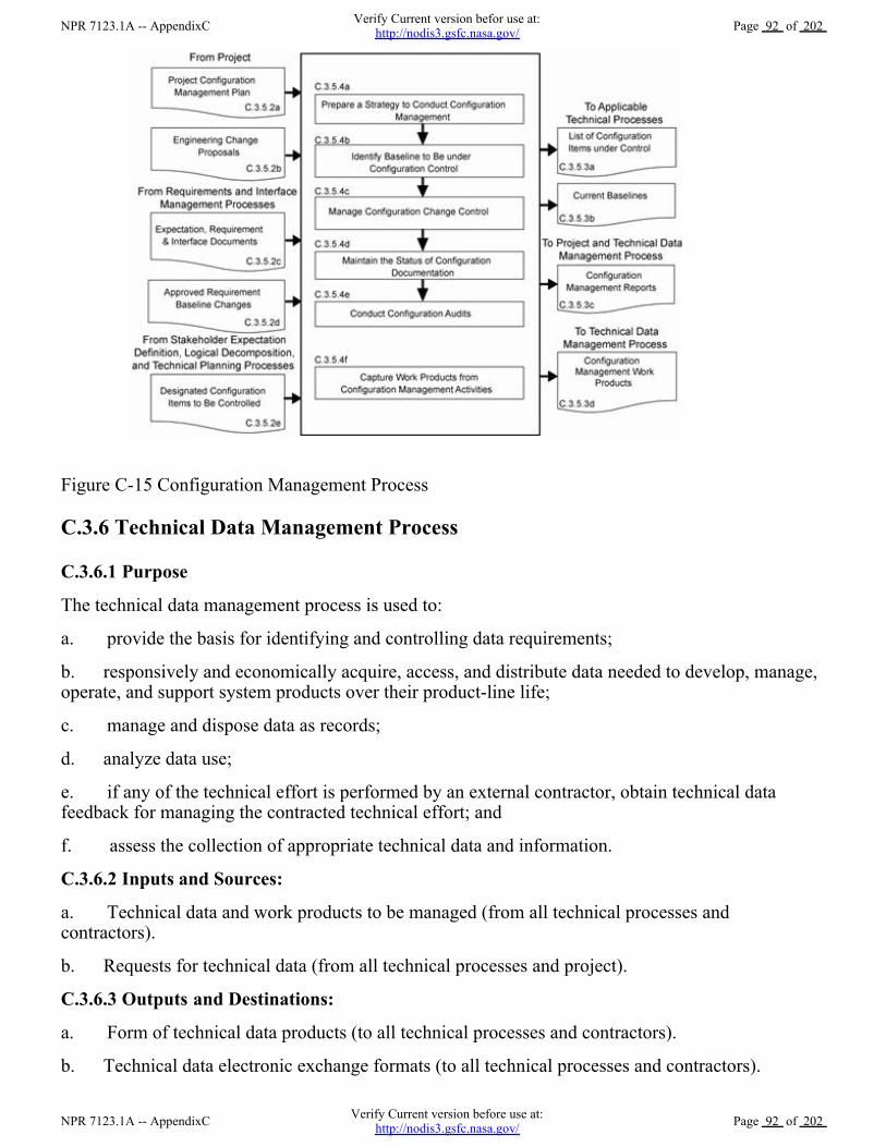
Figure C-15 Configuration Management Process
C.3.6 Technical Data Management Process
C.3.6.1 Purpose
The technical data management process is used to:
a. provide the basis for identifying and controlling data requirements;
b. responsively and economically acquire, access, and distribute data needed to develop, manage,operate, and support system products over their product-line life;
c. manage and dispose data as records;
d. analyze data use;
e. if any of the technical effort is performed by an external contractor, obtain technical datafeedback for managing the contracted technical effort; and
f. assess the collection of appropriate technical data and information.
C.3.6.2 Inputs and Sources:
a. Technical data and work products to be managed (from all technical processes andcontractors).
b. Requests for technical data (from all technical processes and project).
C.3.6.3 Outputs and Destinations:
a. Form of technical data products (to all technical processes and contractors).
b. Technical data electronic exchange formats (to all technical processes and contractors).
NPR 7123.1A -- AppendixCVerify Current version before use at:
http://nodis3.gsfc.nasa.gov/Page 92 of 202
NPR 7123.1A -- AppendixCVerify Current version befor use at:
http://nodis3.gsfc.nasa.gov/Page 92 of 202

c. Delivered technical data (to project and all technical processes).
C.3.6.4 Activities
For the WBS model in the system structure, the following activities are typically performed:
a. Prepare a strategy for the conduct of technical data management to include: (1) determiningrequired data content and form and electronic data exchange interfaces in accordance withinternational standards or agreements; (2) establishing a framework for technical data flow within theproject technical processes and to/from contractors; (3) designating technical data managementresponsibilities and authorities regarding origination, generation, capture, archiving, security,privacy, and disposition of technical data work products; (4) establishing the rights, obligations, andcommitments regarding the retention of, transmission of, and access to technical data items; (5)establishing relevant data storage, transformation, transmission, and presentation standards andconventions to be used; (6) establishing project or program policy and agreements or legislativeconstraints; (7) describing the methods, tools, and metrics used during the technical effort and fortechnical data management; and (8) training appropriate technical team members and support andmanagement personnel in the established technical data management strategy and related proceduresand tools.
b. Collect and store required technical data to include: (1) identifying existing sources oftechnical data that are designated as outputs of the common technical processes; (2) collecting andstoring technical data in accordance with the technical data management strategy and procedures; (3)recording and distributing lessons learned; (4) performing technical data integrity checks oncollected data to confirm compliance with content and format requirements and identifying errors inspecifying or recording data; and (5) prioritizing, reviewing, and updating technical data collectionand storage procedures.
c. Maintain stored technical data to include: (1) managing the databases to maintain properquality and integrity of the collected and stored technical data and to confirm that the technical datais secure and is available to those with authority to have access; (2) performing technical datamaintenance as required; (3) preventing the stored data from being used or accessed inappropriately;(4) maintaining the stored technical data in a manner that protects it against foreseeable hazards, suchas fire, flood, earthquake, and riots; and (5) maintaining periodic backups of each technical database.
d. Provide technical data to authorized parties to include: (1) maintaining an information libraryor reference index to provide data available and access instructions; (2) receiving and evaluatingrequests for technical data and delivery instructions; (3) confirming that required and requestedtechnical data is appropriately distributed to satisfy the needs of the requesting party and inaccordance with established procedures, directives, and agreements; (4) confirming that electronicaccess rules are followed before allowing access to the database and before any data is electronicallyreleased/transferred to the requester; and (5) providing proof of correctness, reliability, and securityof technical data provided to internal and external recipients.
C.3.6.5 Process Flow Diagram
A typical process flow diagram for technical data management is provided in Figure C-16 withinputs and their sources and the outputs and their destinations. The activities of the technical datamanagement process are truncated to indicate the action and object of the action.
NPR 7123.1A -- AppendixCVerify Current version before use at:
http://nodis3.gsfc.nasa.gov/Page 93 of 202
NPR 7123.1A -- AppendixCVerify Current version befor use at:
http://nodis3.gsfc.nasa.gov/Page 93 of 202

Figure C-16 Technical Data Management Process
C.3.7 Technical Assessment Process
C.3.7.1 Purpose
The technical assessment process is used to help monitor progress of the technical effort and providestatus information for support of the system design, product realization, and technical managementprocesses.
C.3.7.2 Inputs and Sources:
a. Process and product measures (from Technical Planning Process).
b. Technical plans including the SEMP (from Technical Planning Process).
c. Risk reporting requirements during technical reviews (from project).
d. Technical cost and schedule status reports (from project).
e. Product measurements (from Product Verification and Product Validation Processes).
f. Decision support recommendations and impacts (from Decision Analysis Process).
C.3.7.3 Outputs and Destinations:
a. Assessment results and findings including technical performance measurement estimates ofmeasures (to Technical Planning, Technical Risk Management, and Requirements ManagementProcesses).
b. Analysis support requests (to Decision Analysis Process).
c. Technical review reports (to project and Technical Data Management Process).
d. Corrective action and requirement change recommendations including actions to correctout-of-tolerance TPMs (to Technical Planning, Requirements Management, and InterfaceManagement Processes).
e. Work products from technical assessment activities (to Technical Data Management Process).
C.3.7.4 Activities
NPR 7123.1A -- AppendixCVerify Current version before use at:
http://nodis3.gsfc.nasa.gov/Page 94 of 202
NPR 7123.1A -- AppendixCVerify Current version befor use at:
http://nodis3.gsfc.nasa.gov/Page 94 of 202

For the WBS model in the system structure, the following activities are typically performed:
a. Prepare a strategy for conducting technical assessments to include: (1) identifying the plansagainst which progress and achievement of the technical effort are to be assessed; (2) establishingprocedures for obtaining cost expenditures against work planned and task completions againstschedule; (3) identifying and obtaining technical requirements against which product developmentprogress and achievement will be assessed and establishing the procedures for conducting theassessments; (4) establishing events when TPMs, estimation or measurement techniques, and rulesfor taking action when out-of-tolerance conditions exist will be assessed; (5) identifying andplanning for phase-to-phase technical reviews and WBS model-to-model vertical progress reviews,as well as establishing review entry and success criteria, review board members, and close-outprocedures; (6) establishing which technical effort work products will undergo peer review, the teammembers who will perform the peer reviews, and reporting requirements; and (7) training teammembers, support staff, and managers involved in conducting technical assessment activities.
b. Assess technical work productivity (progress and achievement against plans) to include: (1)identifying, collecting, and analyzing process measures (e.g., earned value measurements formeasuring progress against planned cost, schedule, resource use, and technical effort tasks) andidentifying and reporting cost-effective changes to correct variances; (2) monitoring stakeholderinvolvement according to the SEMP; and (3) monitoring technical data management against plans.
c. Assess product quality (progress and achievements against technical requirements) to include:(1) identifying, collecting, and analyzing the degree of technical requirement and TPM satisfaction;(2) assessing the maturity of the WBS-model products and services as applicable to the product-linelife-cycle phases; (3) determining any variances from expected values of product performance andidentifying and defining cost-effective changes to correct variances.
Note: Product measures tell the degree of satisfaction of stakeholder expectations and deliver anever improving value to the customers of system products and services. Product measures alsoindicate that the design process is continuing in the direction of an acceptable solution. An exampleof an input product measure is the quality of materials and skills of assigned project personnel. Anexample of an output metric is a TPM. A TPM provides an early warning of the adequacy of adesign in satisfying selected critical technical parameter requirements. A "critical technicalparameter" is one that characterizes a significant total system qualifier (e.g., one or more of theMOPs). TPMs also examine the marginal cost benefit of performance in excess of requirements. Inaddition, it should be possible to project the evolution of the parameter as a function of time towardthe desired value at the completion of development. The projection can be based on test, planning,or historical data.
d. Conduct technical reviews to include: (1) identifying the type of technical reviews and eachreview's purpose and objectives (see Chapter 5 for specific technical reviews that apply); (2)determining progress toward satisfying entry criteria; (3) establishing the makeup of the reviewteam; (4) preparing the review presentation materials; and (5) identifying and resolving action itemsresulting from the review.
Note 1: Reviews are typically closed out when the minutes have been prepared, approved, anddistributed; action items have been resolved; and the review completion documented and signed offby the review chairperson.
Note 2: This activity includes peer reviews, which are planned, focused reviews by technical teampeers on a single work product with the intent of identifying issues prior to that work productmoving on to the next step. A peer review includes planning, preparing, conducting, analyzingoutcomes, and identifying and implementing corrective actions.
NPR 7123.1A -- AppendixCVerify Current version before use at:
http://nodis3.gsfc.nasa.gov/Page 95 of 202
NPR 7123.1A -- AppendixCVerify Current version befor use at:
http://nodis3.gsfc.nasa.gov/Page 95 of 202

e. Capture work products from the conduct of technical assessment activities to include: (1)identifying variances resulting from technical assessments; (2) identifying and reporting changes tocorrect variances; (3) recording methods used in doing assessment activities; (4) documentingassumptions made in arriving at the process and product measure outcomes; and (5) reportingcorrective action recommendations.
C.3.7.5 Process Flow Diagram
A typical process flow diagram for technical assessment is provided in Figure C-17 with inputs andtheir sources and the outputs and their destinations. The activities of the technical assessmentprocess are truncated to indicate the action and object of the action.
Figure C17 Technical Assessment Process
C.3.8 Decision Analysis Process
C.3.8.1 Purpose
The decision analysis process including data collection (e.g., engineering performance, quality, andreliability data) is used to help evaluate technical decision issues, technical alternatives, and theiruncertainties to support decisionmaking. This process is used throughout technical management,system design, and product realization processes to evaluate the impact of decisions on performance,cost, schedule, and technical risk.
C.3.8.2 Inputs and Sources:
a. Decisions needed, alternatives, issues, or problems and supporting data (from all TechnicalProcesses).
NPR 7123.1A -- AppendixCVerify Current version before use at:
http://nodis3.gsfc.nasa.gov/Page 96 of 202
NPR 7123.1A -- AppendixCVerify Current version befor use at:
http://nodis3.gsfc.nasa.gov/Page 96 of 202

b. Analysis support requests (from Technical Assessment Process).
C.3.8.3 Outputs and Destinations:
a. Alternative selection recommendations and impacts (to all Technical Processes)
b. Decision support recommendations and impacts (to Technical Assessment Process)
c. Work products of decision analysis activities (to Technical Data Management Process).
C.3.8.4 Activities
For the WBS model in the system structure, the following activities are typically performed:
a. Establish guidelines to determine which technical issues are subject to a formalanalysis/evaluation process to include: (1) when to use a formal decisionmaking procedure, forexample, as a result of an effectiveness assessment, a technical tradeoff, a problem needing to besolved, action needed as a response to risk exceeding the acceptable threshold, verification orvalidation failure, make/buy choice, evaluating a solution alternative, or resolving a requirementsconflict; (2) what needs to be documented; (3) who will be the decision makers and theirresponsibilities and decision authorities; and (4) how decisions will be handled that do not require aformal evaluation procedure.
b. Define the criteria for evaluating alternative solutions to include: (1) the types of criteria toconsider, including technology limitations, environmental impact, safety, risks, total ownership andlife-cycle costs, and schedule impact; (2) the acceptable range and scale of the criteria; and (3) therank of each criterion by its importance.
c. Identify alternative solutions to address decision issues to include alternatives forconsideration in addition to those that may be provided with the issue.
d. Select evaluation methods and tools/techniques based on the purpose for analyzing a decisionand on the availability of the information used to support the method and/or tool.
Note: Typical evaluation methods include: simulations; weighted trade-off matrices; engineering, manufacturing, cost, and technical opportunity studies; surveys ;extrapolations based on field experience and prototypes; user review and comment; and testing.
e. Evaluate alternative solutions with the established criteria and selected methods to include: (1)evaluation of assumptions related to evaluation criteria and of the evidence that supports theassumptions; and (2) evaluation of whether uncertainty in the values for alternative solutions affectsthe evaluation.
f. Select recommended solutions from the alternatives based on the evaluation criteria to includedocumenting the information that justifies the recommendations and gives the impacts of taking therecommended course of action.
g. Report the analysis/evaluation results/findings with recommendations, impacts, and correctiveactions.
h. Capture work products from decision analysis activities to include: (1) decision analysisguidelines generated and strategy and procedures used; (2) analysis/evaluation approach, criteria,and methods and tools used; (3) analysis/evaluation results, assumptions made in arriving atrecommendations, uncertainties, and sensitivities of the recommended actions or corrective actions;and (4) lessons learned and recommendations for improving future decision analyses.
NPR 7123.1A -- AppendixCVerify Current version before use at:
http://nodis3.gsfc.nasa.gov/Page 97 of 202
NPR 7123.1A -- AppendixCVerify Current version befor use at:
http://nodis3.gsfc.nasa.gov/Page 97 of 202

C.3.8.5 Process Flow Diagram
A typical process flow diagram for technical decision analyses is provided in Figure C-18 withinputs and their sources and the outputs and their destinations. The activities of the decision analysisprocess are truncated to indicate the action and object of the action.
Figure C18 Decision Analysis Process
NPR 7123.1A -- AppendixCVerify Current version before use at:
http://nodis3.gsfc.nasa.gov/Page 98 of 202
NPR 7123.1A -- AppendixCVerify Current version befor use at:
http://nodis3.gsfc.nasa.gov/Page 98 of 202
Appendix D. Systems EngineeringManagement Plan
D.1 Purpose and Use
The purpose of this appendix is to provide an annotated outline for a SEMP for use by NASA inplanning the technical effort required for in-house and contracted projects. The SEMP is thetechnical planning document for systems engineering. The SEMP is designed to be a single,integrated technical planning document for the conduct and management of the required technicaleffort that is the responsibility of an in-house NASA project. The resulting technical plan is torepresent the agreed-to and approved tailoring of the requirements of the SE NPR to satisfy projecttechnical requirements. The plan is to be used by the technical team responsible for generatingtechnical work products to integrate and manage the full spectrum of technical activities required toengineer the system covered by the SEMP. The SEMP should be coordinated with the project planfor integration of the technical planning and modifications related to the allocated resources,including cost, schedule, personnel, facilities, and deliverables required. The plan will also be usedto evaluate the team's technical approach, to make technical risk assessments, and to measureprogress.
D.2 Terms Used
Terminology is a key factor in ensuring a common understanding of the technical effort to beaccomplished. Terms used in the SEMP must have the same meaning as the terms used in the SENPR.
D.3 SEMP Preparation
D.3.1 Outline Use
The SEMP outline in this appendix is to be used in preparing a project SEMP. For a small project thematerial in the SEMP can be placed in the project plan's technical summary and this annotatedoutline used as a topic guide.
D.3.2 Tailoring and Waivers
D.3.2.1
SEMP tailoring is to be consistent with the SE NPR tailoring requirements and guidelines. (See
NPR 7123.1A -- AppendixDVerify Current version before use at:
http://nodis3.gsfc.nasa.gov/Page 99 of 202
NPR 7123.1A -- AppendixDVerify Current version befor use at:
http://nodis3.gsfc.nasa.gov/Page 99 of 202

Appendix F.) The SEMP is to include documentation of any tailoring to the SE NPR requirementsand SEMP sections or subsections. Tailoring is an adaptation of a process or approach to meet arequirement, whereas a waiver is a documented agreement intentionally releasing a program orproject from meeting a requirement. Tailored requirements will be documented directly followingthe heading of each affected SEMP section or subsection. Tailored SE NPR requirements that are notdirectly related to a SEMP section or subsection will be documented in the waiver section.
D.3.2.2
Approved waivers will be documented and incorporated into the waiver section of the SEMP.
D.3.3 Surveillance-Type Projects
For projects with significant portions of the engineering work contracted out, the SEMP shouldscope and plan the NASA project's implementation of the common technical processes before,during, and at the completion of the contracted effort. This should include planning the technicalteam's involvement in RFP preparation, in source selection activities, and in acceptance ofdeliverables. The interface activities with the contractor, including NASA technical teaminvolvement with and monitoring of contracted work, should be a focus of the SEMP.
D.4 SEMP Annotated Outline
D.4.1 General Structure
The SEMP contains the following sections, unless they have been tailored out. Cross references todetailed information in related technical plans are included in each pertinent SEMP section.
a. Purpose and Scope.
b. Applicable Documents and Designated Governing Authority.
c. Technical Summary.
d. Technical Effort Integration.
e. Common Technical Processes Implementation.
f. Technology Insertion.
g. Additional SE Functions and Activities.
h. Integration with the Project Plan Resource Allocation.
i. Waivers.
j. Appendices.
D.4.2 Purpose and Scope
This section provides a brief description of the purpose, scope, and content of the SEMP. The scope
NPR 7123.1A -- AppendixDVerify Current version before use at:
http://nodis3.gsfc.nasa.gov/Page 100 of 202
NPR 7123.1A -- AppendixDVerify Current version befor use at:
http://nodis3.gsfc.nasa.gov/Page 100 of 202

encompasses the SE technical effort required to generate the work products necessary to meet theexit criteria for the product-line life-cycle phases.
D.4.3 Applicable Documents
This section lists the documents applicable to SEMP implementation and describes major standardsand procedures that the technical effort needs to follow. Specific implementation of standardizationtasking is incorporated into pertinent sections of the SEMP.
D.4.4 Technical Summary
This section contains an executive summary describing the problem to be solved by this technicaleffort.
D.4.4.1 System Description
This subsection contains a definition of the purpose of the system being developed and a briefdescription of the purpose of the products of the WBS models of the system structure for which thisSEMP applies. Each WBS model includes the system end products and their subsystems and thesupporting or enabling products and any other work products (plans, baselines) required for thedevelopment of the system. The description should include any interfacing systems and systemproducts, including humans, with which the WBS model system products will interact physically,functionally, or electronically.
D.4.4.2 System Structure
This subsection contains an explanation of how the WBS models will be developed, how theresulting WBS model will be integrated into the project WBS, and how the overall system structurewill be developed. This subsection contains a description of the relationship of the specification treeand the drawing tree with the products of the system structure and how the relationship andinterfaces of the system end products and their life-cycle-enabling products will be managedthroughout the planned technical effort.
D.4.4.3 Product Integration
This subsection contains an explanation of how the product will be integrated and will describe clearorganizational responsibilities and interdependencies whether the organizations are geographicallydispersed or managed across Centers.
D.4.4.4 Planning Context
This subsection contains the product-line life-cycle model constraints (e.g., NPR 7120.5) that affectthe planning and implementation of the common technical processes to be applied in performing thetechnical effort. The constraints provide a linkage of the technical effort with the applicableproduct-line life-cycle phases covered by the SEMP including, as applicable, milestone decisiongates, major technical reviews, key intermediate events leading to project completion, life-cyclephase, event entry and exit criteria, and major baseline and other work products to be delivered tothe sponsor or customer of the technical effort.
NPR 7123.1A -- AppendixDVerify Current version before use at:
http://nodis3.gsfc.nasa.gov/Page 101 of 202
NPR 7123.1A -- AppendixDVerify Current version befor use at:
http://nodis3.gsfc.nasa.gov/Page 101 of 202

D.4.4.5 Boundary of Technical Effort
This subsection contains a description of the boundary of the general problem to be solved by thetechnical effort. Specifically, it identifies what can be controlled by the technical team (inside theboundary) and what influences the technical effort and is influenced by the technical effort but notcontrolled by the technical team (outside the boundary). Specific attention should be given tophysical, functional, and electronic interfaces across the boundary.
D.4.4.6 Cross-References
This subsection contains cross-references to appropriate nontechnical plans that interface with thetechnical effort and contains a summary description of how the technical activities covered in otherplans are accomplished as fully integrated parts of the technical effort.
D.4.5 Technical Effort Integration
This section contains a description of how the various inputs to the technical effort will be integratedinto a coordinated effort that meets cost, schedule, and performance objectives.
D.4.5.1 Responsibility and Authority
This subsection contains a description of the organizing structure for the technical teams assigned tothis technical effort and includes how the teams will be staffed and managed, including: (a) whatorganization/panel will serve as the DGA for this project and, therefore, will have final signatureauthority for this SEMP; (b) how multidisciplinary teamwork will be achieved; (c) identification anddefinition of roles, responsibilities, and authorities required to perform the activities of each plannedcommon technical process; (d) planned technical staffing by discipline and expertise level, withhuman resource loading; (e) required technical staff training; and (f) assignment of roles,responsibilities, and authorities to appropriate project stakeholders or technical teams to assureplanned activities are accomplished.
D.4.5.2 Contractor Integration
This subsection contains a description of how the technical effort of in-house and externalcontractors is to be integrated with the NASA technical team efforts. This includes establishingtechnical agreements, monitoring contractor progress against the agreement, handling technicalwork or product requirements change requests, and acceptance of deliverables. The section willspecifically address how interfaces between the NASA technical team and the contractor will beimplemented for each of the 17 common technical processes. For example, it addresses how theNASA technical team will be involved with reviewing or controlling contractor-generated designsolution definition documentation or how the technical team will be involved with productverification and product validation activities.
D.4.5.3 Support Integration
This subsection contains a description of the methods (such as integrated computer-aided tool sets,integrated work product databases, and technical management information systems) that will beused to support technical effort integration.
D.4.6 Common Technical Processes Implementation
NPR 7123.1A -- AppendixDVerify Current version before use at:
http://nodis3.gsfc.nasa.gov/Page 102 of 202
NPR 7123.1A -- AppendixDVerify Current version befor use at:
http://nodis3.gsfc.nasa.gov/Page 102 of 202

Each of the 17 common technical processes will have a separate subsection that contains the plan forperforming the required process activities as appropriately tailored. (See Chapter 3 for the processactivities required and Appendix F for tailoring.) Implementation of the 17 common technicalprocesses includes: (1) generating outcomes needed to satisfy the entry and exit criteria of theapplicable product-line life-cycle phase or phases identified in D.4.4.4 and (2) producing thenecessary inputs for other technical processes. These sections contain a description of the approach,methods, and tools for:
a. Identifying and obtaining adequate human and nonhuman resources for performing the plannedprocess, developing the work products, and providing the services of the process.
b. Assigning responsibility and authority for performing the planned process, developing the workproducts, and providing the services of the process.
c. Training the technical staff performing or supporting the process, where training is identified asneeded.
d. Designating and placing designated work products of the process under appropriate levels ofconfiguration management.
e. Identifying and involving stakeholders of the process.
f. Monitoring and controlling the process.
g. Objectively evaluating adherence of the process and the work products and services of the processto the applicable requirements, objectives, and standards and addressing noncompliance.
h. Reviewing activities, status, and results of the process with appropriate levels of management andresolving issues.
D.4.7 Technology Insertion
This section contains a description of the approach and methods for identifying key technologies andtheir associated risks and criteria for assessing and inserting technologies, including those forinserting critical technologies from technology development projects.
D.4.8 Additional SE Functions and Activities
This section contains a description of other areas not specifically included in previous sections butthat are essential for proper planning and conduct of the overall technical effort.
D.4.8.1 System Safety
This subsection contains a description of the approach and methods for conducting safety analysisand assessing the risk to operators, the system, the environment, or the public.
D.4.8.2 Engineering Methods and Tools
This subsection contains a description of the methods and tools not included in D.4.7 that are neededto support the overall technical effort and identifies those tools to be acquired and tool trainingrequirements.
NPR 7123.1A -- AppendixDVerify Current version before use at:
http://nodis3.gsfc.nasa.gov/Page 103 of 202
NPR 7123.1A -- AppendixDVerify Current version befor use at:
http://nodis3.gsfc.nasa.gov/Page 103 of 202

D.4.8.3 Specialty Engineering
This subsection contains a description of engineering discipline and specialty requirements thatapply across projects and the WBS models of the system structure. Examples of these requirementareas include planning for safety, reliability, human factors, logistics, maintainability, quality,operability, and supportability.
D.4.9 Integration with the Project Plan and Technical Resource Allocation
This section contains how the technical effort will integrate with project management and definesroles and responsibilities. This section addresses how technical requirements will be integrated withthe project plan to determinate the allocation of resources, including cost, schedule, and personnel,and how changes to the allocations will be coordinated.
D.4.10 Waivers
This section contains all approved waivers to the Center Director's SE NPR Implementation Planrequirement for the SEMP. This section also contains a separate subsection that includes any tailoredSE NPR requirements that are not related and able to be documented in a specific SEMP section orsubsection.
D.4.11 Appendices
Appendices are included, as necessary, to provide a glossary, acronyms and abbreviations, andinformation published separately for convenience in document maintenance. Included would be: (a)information that may be pertinent to multiple topic areas (e.g., description of methods orprocedures); (b) charts and proprietary data applicable to the technical efforts required in the SEMP;and (c) a summary of technical plans associated with the project. Each appendix should bereferenced in one of the sections of the engineering plan where data would normally have beenprovided.
NPR 7123.1A -- AppendixDVerify Current version before use at:
http://nodis3.gsfc.nasa.gov/Page 104 of 202
NPR 7123.1A -- AppendixDVerify Current version befor use at:
http://nodis3.gsfc.nasa.gov/Page 104 of 202

Appendix E. Hierarchy of Related NASADocuments
NPR 7123.1A -- AppendixEVerify Current version before use at:
http://nodis3.gsfc.nasa.gov/Page 105 of 202
NPR 7123.1A -- AppendixEVerify Current version befor use at:
http://nodis3.gsfc.nasa.gov/Page 105 of 202

Appendix F. Tailoring
F.1 Tailoring is the documentation and approval of the adaptation of the processes and approach tocomplying with requirements according to the purpose, complexity, and scope of a NASA programor project. Tailoring, including rationale for modifications, additions, or deletions should beapproved by the DGA.
F.2 Each project following this SE NPR needs to tailor to the specific needs of a particular project,phase, or acquisition structure. Tasks that add unnecessary costs or data and any factors that do notadd value to the project should be eliminated. Tailoring takes the form of modification or addition.
F.3 Tailoring specific tasks requires definition of the depth of detail, level of effort, and the dataexpected. Tailoring is performed to both breadth and depth based on the project and specific phaseof the life cycle. "Tailoring in breadth" deals with factors that can include types and numbers ofsystems impacted by the development of a new subsystem, the numbers and types of assessments,and numbers and types of reviews. "Tailoring in depth" involves decisions concerning the level ofdetail needed to generate and substantiate the requirements. The depth of the SE effort varies fromproject to project in relation to complexity, uncertainty, urgency, and the willingness to accept risk.
F.4 The objectives of the effort, the scope of the SE process, and the breadth and depth of applicationneed to be considered. To assist in defining the depth of application and level of effort, the followingshould be evaluated as part of the tailoring process of this SE NPR:
a. The level of detail in system definition required from the in-house Government or contractedeffort.
b. The directions and limitations of tasks including willingness to accept risk.
c. The scenarios and missions to be examined for each primary system function.
d. A set of measures of effectiveness.
e. Known constraints in areas where they exist but quantitative data is not available.
f. The technology database including identification of key technologies, performance, maturity, cost,risks, schedule, and any limiting criteria on the use of technologies.
g. The factors essential to system success, including those factors related to major risk areas (e.g.,budget, resources, and schedule).
h. Technical demonstration and confirmation events that need to be conducted (including technicalreviews).
i. The goals and constraints of the project.
j. The organizational and contractual requirements for SE processes.
k. The baseline SE process for the organization and tailoring guidelines.
l. Any cost targets and the acceptable level of risk.
F.5 The basic SE tailoring process can be applied to any development effort (including newdevelopments, modifications, and product improvements) regardless of size or complexity. Attention
NPR 7123.1A -- AppendixFVerify Current version before use at:
http://nodis3.gsfc.nasa.gov/Page 106 of 202
NPR 7123.1A -- AppendixFVerify Current version befor use at:
http://nodis3.gsfc.nasa.gov/Page 106 of 202

to scope of the effort and level of output expected is essential. A revolutionary new systemdevelopment, for example, in Formulation will not usually require formal configurationmanagement audits or formal change control mechanisms. However, conceptual explorationinvestigation of modifications to an existing developed system may need this type of activity.
F.6 The level of detail expected from the system products of the technical effort needs to beidentified. This will determine the depth to which the SE process is executed. For example,functional analysis and synthesis are conducted to a sufficiently detailed depth to identify areas oftechnical risk based on the life-cycle phase or effort.
F.7 The term "sufficiently detailed" is determined based on the objectives of the project and can becharacterized by the information content expected from the physical architecture. Throughout thelife cycle, the level of detail may vary since the baseline system may be at one level of detail andproduct improvements or other modifications may be at a different level of detail. Note that level ofdetail needed from the technical effort to ensure adequacy of technical definition, design, anddevelopment is not synonymous with the level of detail expected for management control andreporting (e.g., cost performance reports).
F.8 The primary output of the SE tailoring process for a project is documented in the SEMP. Theform of the SEMP will vary depending on the size, complexity and acceptable cost or risk level ofthe project.
References
The following documents were used as reference materials in the development of this appendix:
a. Defense Acquisition University Systems Engineering Fundamentals. Ft. Belvoir, Virginia:Defense Acquisition University Press, December 2000.
b. International Council on Systems Engineering (INCOSE) Systems Engineering Guide.
NPR 7123.1A -- AppendixFVerify Current version before use at:
http://nodis3.gsfc.nasa.gov/Page 107 of 202
NPR 7123.1A -- AppendixFVerify Current version befor use at:
http://nodis3.gsfc.nasa.gov/Page 107 of 202

Appendix G. Technical Review Entrance andSuccess Criteria
This appendix describes the recommended best practices for entrance and success criteria for thetechnical reviews required in Chapter 5.
G.1 Program\System Requirements Review
The P/SRR is used to ensure that the program requirements are properly formulated and correlatedwith the Agency and mission directorate strategic objectives.
Table G-1 P/SRR Entrance and Success Criteria
Program/System Requirements Review
Entrance Criteria Success Criteria
1. A Formulation Authorization Document
(FAD) has been approved.
2. Program requirements have been defined
that support mission directorate
requirements on the program.
3. Major program risks and corresponding
mitigation strategies have been identified.
4. The high-level program requirements
have been documented to include:
a. performance,
b. safety, and
c. programmatic requirements.
5. An approach for verifying compliance
with program requirements has been defined.
6. Procedures for controlling changes to
program requirements have been defined and
approved.
7. Traceability of program requirements to
individual projects is documented in
accordance with Agency needs, goals, and
objectives, as described in the NASA
1. With respect to mission and science
requirements, defined high-level program
requirements are determined to be complete
and are approved.
2. Defined interfaces with other programs
are approved.
3. The program requirements are
determined to provide a cost-effective
program.
4. The program requirements are
adequately levied on either the
single-program project or the multiple
projects of the program.
5. The plans for controlling program
requirement changes have been approved.
6. The approach for verifying compliance
with program requirements has been
approved.
7. The mitigation strategies for handling
identified major risks have been approved.
NPR 7123.1A -- AppendixGVerify Current version before use at:
http://nodis3.gsfc.nasa.gov/Page 108 of 202
NPR 7123.1A -- AppendixGVerify Current version befor use at:
http://nodis3.gsfc.nasa.gov/Page 108 of 202

Strategic Plan.
8. Top program/project risks with
significant technical, safety, cost, and
schedule impacts are identified.
G.2 Program/System Definition Review
The P/SDR applies to all NASA space flight programs to ensure the readiness of these programs toenter an approved Program Commitment Agreement (PCA). The approved PCA permits programsto transition from the program formulation phase to the program implementation phase. A ProgramApproval Review (PAR) is conducted as part of the P/SDR to provide Agency management with anindependent assessment of the readiness of the program to proceed into implementation.
The P/SDR examines the proposed program architecture and the flow down to the functionalelements of the system. The proposed program's objectives and the concept for meeting thoseobjectives are evaluated. Key technologies and other risks are identified and assessed. The baselineProgram Plan, budgets, and schedules are presented.
The technical team provides the technical content to support the P/SDR.
Table G-2 P/SDR Entrance and Success Criteria
Program/System Definition Review
Entrance Criteria Success Criteria
1. A Program/System Requirements
Review has been satisfactorily completed.
2. A program plan has been prepared that
includes the following:
a. how the program will be managed;
b. a list of specific projects;
c. the high-level program requirements
(including risk criteria);
d. performance, safety, and programmatic
requirements correlated to Agency and
directorate strategic objectives;
e. description of the systems to be
developed (hardware and software), legacy
systems, system interfaces, and facilities; and
f. identification of major constraints
affecting system development (e.g., cost,
launch window, required launch vehicle,
mission planetary environment, engine
1. An approved program plan and
management approach.
2. Approved SEMP and technical approach.
3. Estimated costs are adequate.
4. Documentation for obtaining the Program
Commitment Agreement is approved.
5. An approved draft program control plan.
6. Agreement that the program is aligned
with the Agency needs, goals and objectives.
7. The technical approach is adequate.
8. The schedule is adequate and consistent
with cost, risk and mission goals.
9. Resources other than budget are adequate
and available.
NPR 7123.1A -- AppendixGVerify Current version before use at:
http://nodis3.gsfc.nasa.gov/Page 109 of 202
NPR 7123.1A -- AppendixGVerify Current version befor use at:
http://nodis3.gsfc.nasa.gov/Page 109 of 202

design, international partners, and
technology drivers).
3. Program level SEMP which includes
project technical approaches and
management plans to implement the
allocated program requirements including
constituent launch, flight, and ground
systems, and operations and logistics
concepts.
4. Independent Cost Analyses (ICAs) and
Independent Cost Estimates (ICEs).
5. Management plan for resources other
than budget.
6. Documentation for obtaining the
program commitment agreement that
includes the following:
a. the feasibility of the program mission
solution with a cost estimate within
acceptable cost range,
b. project plans adequate for project
formulation initiation,
c. identified and prioritized program
concept evaluation criteria to be used in
project evaluations,
d. estimates of required annual funding
levels,
e. credible program cost and schedule
allocation estimates to projects,
f. acceptable risk and mitigation strategies
(supported by a technical risk assessment),
g. organizational structures and defined
work assignments,
h. defined program acquisition strategies.
i. interfaces to other programs and partners,
j. a draft plan for program implementation,
and
k. a defined program management system.
7. A draft program control plan that
NPR 7123.1A -- AppendixGVerify Current version before use at:
http://nodis3.gsfc.nasa.gov/Page 110 of 202
NPR 7123.1A -- AppendixGVerify Current version befor use at:
http://nodis3.gsfc.nasa.gov/Page 110 of 202

G.3
Mission Concept Review
The MCR affirms the mission need and examines the proposed mission's objectives and the conceptfor meeting those objectives.
Table G-3 MCR Entrance and Success Criteria
Mission Concept Review
Entrance Criteria Success Criteria
1. Mission goals and objectives.
2. Analysis of alternative concepts to show
at least one is feasible.
3. Concept of operations.
4. Preliminary mission descope options.
5. Preliminary risk assessment, including
technologies and associated risk
management/mitigation strategies and
options.
6. Conceptual test and evaluation strategy.
7. Preliminary technical plans to achieve
1. Mission objectives are clearly defined
and stated and are unambiguous and
internally consistent.
2. The preliminary set of requirements
satisfactorily provides a system that will
meet the mission objectives.
3. The mission is feasible. A solution has
been identified that is technically feasible. A
rough cost estimate is within an acceptable
cost range.
4. The concept evaluation criteria to be
used in candidate systems evaluation have
been identified and prioritized.
includes:
a. how the program plans to control
program requirements, technical design,
schedule, and cost to achieve its high-level
requirements;
b. how the requirements, technical design,
schedule, and cost of the program will be
controlled;
c. how the program will utilize its
technical, schedule, and cost reserves to
control the baseline;
d. how the program plans to report
technical, schedule, and cost status to the
MDAA, including frequency and the level
of detail; and
e. how the program will address technical
waivers and how dissenting opinions will be
handled.
8. For each project, a top-level description
has been documented.
NPR 7123.1A -- AppendixGVerify Current version before use at:
http://nodis3.gsfc.nasa.gov/Page 111 of 202
NPR 7123.1A -- AppendixGVerify Current version befor use at:
http://nodis3.gsfc.nasa.gov/Page 111 of 202

next phase.
8. Defined MOEs and MOPs.
9. Conceptual life-cycle support strategies
(logistics, manufacturing, and operation).
5. The need for the mission has been
clearly identified.
6. The cost and schedule estimates are
credible.
7. An updated technical search was done to
identify existing assets or products that
could satisfy the mission or parts of the
mission.
8. Technical planning is sufficient to
proceed to the next phase.
9. Risk and mitigation strategies have been
identified and are acceptable based on
technical risk assessments.
G.4 System Requirements Review
The SRR examines the functional and performance requirements defined for the system and thepreliminary program or project plan and ensures that the requirements and the selected concept willsatisfy the mission
Table G-4 SRR Entrance and Success Criteria
System Requirements Review
Entrance Criteria Success Criteria
1. Successful completion of the MCR and
responses made to all MCR Requests for
Actions (RFAs) and Review Item
Discrepancies (RIDs).
2. A preliminary SRR agenda, success
criteria, and charge to the board have been
agreed to by the technical team, project
manager, and review chair prior to the SRR.
3. The following technical products for
hardware and software system elements are
available to the cognizant participants prior
to the review:
a. system requirements document;
b. system software functionality description;
1. The project utilizes a sound process for
the allocation and control of requirements
throughout all levels, and a plan has been
defined to complete the definition activity
within schedule constraints.
2. Requirements definition is complete with
respect to top-level mission and science
requirements, and interfaces with external
entities and between major internal elements
have been defined.
3. Requirements allocation and flow down
of key driving requirements have been
defined down to subsystems.
4. Preliminary approaches have been
determined for how requirements will be
NPR 7123.1A -- AppendixGVerify Current version before use at:
http://nodis3.gsfc.nasa.gov/Page 112 of 202
NPR 7123.1A -- AppendixGVerify Current version befor use at:
http://nodis3.gsfc.nasa.gov/Page 112 of 202

c. updated concept of operations;
d. updated mission requirements, if
applicable;
e. baselined SEMP;
f. risk management plan;
g. preliminary system requirements
allocation to the next lower level system;
h. updated cost estimate;
i. Technology Development Maturity
Assessment Plan;
j. updated risk assessment and mitigations
(including PRA as applicable).
k. logistics documentation (e.g.,
preliminary maintenance plan);
l. preliminary human rating plan, if
applicable;
m. Software Development Plan (SDP);
n. system safety and mission assurance
plan;
o. configuration management plan;
p. initial document tree;
q. verification and validation approach;
r. preliminary system safety analysis; and
s. other specialty disciplines, as required.
verified and validated down to the subsystem
level.
5. Major risks have been identified and
technically assessed, and viable mitigation
strategies have been defined.
G.5 Mission Definition Review
The MDR examines the proposed requirements, the mission architecture, and the flow down to allfunctional elements of the mission to ensure that the overall concept is complete, feasible, andconsistent with available resources.
Table G-5 MDR Entrance and Success Criteria
Mission Definition Review
Entrance Criteria Success Criteria
NPR 7123.1A -- AppendixGVerify Current version before use at:
http://nodis3.gsfc.nasa.gov/Page 113 of 202
NPR 7123.1A -- AppendixGVerify Current version befor use at:
http://nodis3.gsfc.nasa.gov/Page 113 of 202

1. Successful completion of the SRR and
responses made to all SRR RFAs and RIDs.
2. A preliminary MDR agenda, success
criteria, and charge to the board have been
agreed to by the technical team, project
manager, and review chair prior to the MDR.
3. The following technical products for
hardware and software system elements are
available to the cognizant participants prior
to the review:
a. system architecture;
b. updated system requirements
document, if applicable;
c. system software functionality description;
d. updated concept of operations, if
applicable;
e. updated mission requirements, if
applicable;
f. updated SEMP, if applicable;
g. updated risk management plan, if
applicable;
h. Technology Development Maturity
Assessment Plan;
i. preferred system solution definition,
including major trades and options;
j. updated risk assessment and mitigations
(including PRA, as applicable);
k. updated cost and schedule data;
l. logistics documentation (e.g.,
preliminary maintenance plan);
m. Software Development Plan (SDP);
n. system safety and mission assurance
plan;
o. configuration management plan;
p. updated initial document tree, if
applicable;
1. The resulting overall concept is
reasonable, feasible, complete, responsive to
the mission requirements, and is consistent
with system requirements and available
resources (cost, schedule, mass, and power).
2. System and subsystem design
approaches and operational concepts exist
and are consistent with the requirements set.
3. The requirements, design approaches,
and conceptual design will fulfill the mission
needs within the estimated costs.
4. Major risks have been identified and
technically assessed, and viable mitigation
strategies have been defined.
NPR 7123.1A -- AppendixGVerify Current version before use at:
http://nodis3.gsfc.nasa.gov/Page 114 of 202
NPR 7123.1A -- AppendixGVerify Current version befor use at:
http://nodis3.gsfc.nasa.gov/Page 114 of 202
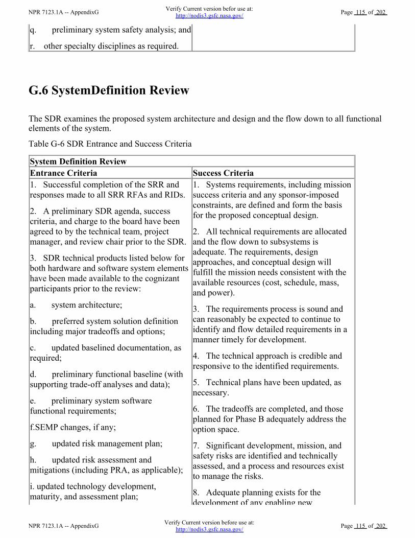
q. preliminary system safety analysis; and
r. other specialty disciplines as required.
G.6 SystemDefinition Review
The SDR examines the proposed system architecture and design and the flow down to all functionalelements of the system.
Table G-6 SDR Entrance and Success Criteria
System Definition Review
Entrance Criteria Success Criteria
1. Successful completion of the SRR and
responses made to all SRR RFAs and RIDs.
2. A preliminary SDR agenda, success
criteria, and charge to the board have been
agreed to by the technical team, project
manager, and review chair prior to the SDR.
3. SDR technical products listed below for
both hardware and software system elements
have been made available to the cognizant
participants prior to the review:
a. system architecture;
b. preferred system solution definition
including major tradeoffs and options;
c. updated baselined documentation, as
required;
d. preliminary functional baseline (with
supporting trade-off analyses and data);
e. preliminary system software
functional requirements;
f.SEMP changes, if any;
g. updated risk management plan;
h. updated risk assessment and
mitigations (including PRA, as applicable);
i. updated technology development,
maturity, and assessment plan;
1. Systems requirements, including mission
success criteria and any sponsor-imposed
constraints, are defined and form the basis
for the proposed conceptual design.
2. All technical requirements are allocated
and the flow down to subsystems is
adequate. The requirements, design
approaches, and conceptual design will
fulfill the mission needs consistent with the
available resources (cost, schedule, mass,
and power).
3. The requirements process is sound and
can reasonably be expected to continue to
identify and flow detailed requirements in a
manner timely for development.
4. The technical approach is credible and
responsive to the identified requirements.
5. Technical plans have been updated, as
necessary.
6. The tradeoffs are completed, and those
planned for Phase B adequately address the
option space.
7. Significant development, mission, and
safety risks are identified and technically
assessed, and a process and resources exist
to manage the risks.
8. Adequate planning exists for the
development of any enabling new
NPR 7123.1A -- AppendixGVerify Current version before use at:
http://nodis3.gsfc.nasa.gov/Page 115 of 202
NPR 7123.1A -- AppendixGVerify Current version befor use at:
http://nodis3.gsfc.nasa.gov/Page 115 of 202

G.7 Preliminary Design Review
The PDR demonstrates that the preliminary design meets all system requirements with acceptablerisk and within the cost and schedule constraints and establishes the basis for proceeding withdetailed design. It will show that the correct design options have been selected, interfaces have beenidentified, and verification methods have been described.
Table G-7 PDR Entrance and Success Criteria
Preliminary Design Review
Entrance Criteria Success Criteria
1. Successful completion of the SDR or MDR
and responses made to all SDR or MDR RFAs
and RIDs, or a timely closure plan exists for those
remaining open.
2. A preliminary PDR agenda, success criteria,
and charge to the board have been agreed to by
the technical team, project manager, and review
chair prior to the PDR.
3. PDR technical products listed below for both
hardware and software system elements have been
made available to the cognizant participants prior
to the review:
a. Updated baselined documentation, as required.
1. The top-level requirements
including mission success criteria,
TPMs, and any sponsor-imposed
constraints are agreed upon, finalized,
stated clearly, and consistent with the
preliminary design.
2. The flow down of verifiable
requirements is complete and proper or,
if not, an adequate plan exists for
timely resolution of open items.
Requirements are traceable to mission
goals and objectives.
3. The preliminary design is expected
to meet the requirements at an
j. updated cost and schedule data;
k. updated logistics documentation;
l. based on system complexity, updated
human rating plan;
m. software test plan;
n. software requirements document(s);
o. interface requirements documents
(including software);
p. technical resource utilization estimates
and margins;
q. updated safety and mission assurance
(S&MA) plan; and
r.updated preliminary safety analysis.
development of any enabling new
technology.
9. The operations concept is consistent with
proposed design concept(s) and is in
alignment with the mission requirements.
NPR 7123.1A -- AppendixGVerify Current version before use at:
http://nodis3.gsfc.nasa.gov/Page 116 of 202
NPR 7123.1A -- AppendixGVerify Current version befor use at:
http://nodis3.gsfc.nasa.gov/Page 116 of 202

b. Preliminary subsystem design
specifications for each configuration item
(hardware and software), with supporting
trade-off analyses and data, as required. The
preliminary software design specification should
include a completed definition of the software
architecture and a preliminary database design
description, as applicable.
c. Updated technology development maturity
assessment plan.
d. Updated risk assessment and mitigation.
e. Updated cost and schedule data.
f. Updated logistics documentation, as required.
g. Applicable technical plans (e.g., technical
performance measurement plan, contamination
control plan, parts management plan,
environments control plan, EMI/EMC control
plan, payload-to-carrier integration plan,
producibility/manufacturability program plan,
reliability program plan, quality assurance plan).
h. Applicable standards.
i. Safety analyses and plans.
j. Engineering drawing tree.
k. Interface control documents.
l. Verification/validation plan.
m. Plans to respond to regulatory requirements
(e.g., Environmental Impact Statement), as
required.
n. Disposal plan.
o. Technical resource utilization estimates and
margins.
p. System-level safety analysis.
q. Preliminary limited life items list (LLIL).
acceptable level of risk.
4. Definition of the technical
interfaces is consistent with the overall
technical maturity and provides an
acceptable level of risk.
5. Adequate technical interfaces are
consistent with the overall technical
maturity and provide an acceptable
level of risk.
6. Adequate technical margins exist
with respect to TPMs.
7. Any required new technology has
been developed to an adequate state of
readiness, or back-up options exist and
are supported to make them a viable
alternative.
8. The project risks are understood
and have been credibly assessed, and
plans, a process, and resources exist to
effectively manage them.
9. Safety and mission assurance (e.g.,
safety, reliability, maintainability,
quality, and EEE parts) have been
adequately addressed in preliminary
designs and any applicable S&MA
products (e.g., PRA, system safety
analysis, and failure modes and effects
analysis) have been approved.
10. The operational concept is
technically sound, includes (where
appropriate) human factors, and
includes the flow down of requirements
for its execution.
G.8 Critical Design Review
NPR 7123.1A -- AppendixGVerify Current version before use at:
http://nodis3.gsfc.nasa.gov/Page 117 of 202
NPR 7123.1A -- AppendixGVerify Current version befor use at:
http://nodis3.gsfc.nasa.gov/Page 117 of 202

The CDR demonstrates that the maturity of the design is appropriate to support proceeding withfull-scale fabrication, assembly, integration, and test. CDR determines that the technical effort is ontrack to complete the flight and ground system development and mission operations, meetingmission performance requirements within the identified cost and schedule constraints.
Table G-8 CDR Entrance and Success Criteria
Critical Design Review
Entrance Criteria Success Criteria
1. Successful completion of the PDR and responses
made to all PDR RFAs and RIDs, or a timely closure
plan exists for those remaining open.
2. A preliminary CDR agenda, success criteria, and
charge to the board have been agreed to by the
technical team, project manager, and review chair prior
to the CDR.
3. CDR technical work products listed below for both
hardware and software system elements have been
made available to the cognizant participants prior to the
review:
a. updated baselined documents, as required;
b. product build-to specifications for each hardware
and software configuration item, along with supporting
trade-off analyses and data;
c. fabrication, assembly, integration, and test plans
and procedures;
d. technical data package (e.g., integrated
schematics, spares provisioning list, interface control
documents, engineering analyses, and specifications);
e. operational limits and constraints;
f. technical resource utilization estimates and margins;
g. acceptance criteria;
h. command and telemetry list;
i. verification plan (including requirements and
specification);
j. validation plan;
k. launch site operations plan;
l. checkout and activation plan;
m. disposal plan (including decommissioning or
1. The detailed design is
expected to meet the requirements
with adequate margins at an
acceptable level of risk.
2. Interface control documents
are sufficiently matured to
proceed with fabrication,
assembly, integration, and test,
and plans are in place to manage
any open items.
3. High confidence exists in the
product baseline, and adequate
documentation exists or will exist
in a timely manner to allow
proceeding with fabrication,
assembly, integration, and test.
4. The product verification and
product validation requirements
and plans are complete.
5. The testing approach is
comprehensive, and the planning
for system assembly, integration,
test, and launch site and mission
operations is sufficient to progress
into the next phase.
6. Adequate technical and
programmatic margins and
resources exist to complete the
development within budget,
schedule, and risk constraints.
7. Risks to mission success are
understood and credibly assessed,
and plans and resources exist to
effectively manage them.
8. Safety and mission assurance
NPR 7123.1A -- AppendixGVerify Current version before use at:
http://nodis3.gsfc.nasa.gov/Page 118 of 202
NPR 7123.1A -- AppendixGVerify Current version befor use at:
http://nodis3.gsfc.nasa.gov/Page 118 of 202

termination);
n. updated Technology Development Maturity
Assessment Plan;
o. updated risk assessment and mitigation;
p. updated reliability analyses and assessments;
q. updated cost and schedule data;
r. updated logistics documentation;
s. software design document(s) (including interface
design documents);
t. updated LLIL;
u. subsystem-level and preliminary operations
safety analyses;
v. systems and subsystem certification plans and
requirements (as needed); and
w. system safety analysis with associated
verifications.
8. Safety and mission assurance
(e.g., safety, reliability,
maintainability, quality, and EEE
parts) have been adequately
addressed in system and
operational designs, and any
applicable S&MA products (e.g.,
PRA, system safety analysis and
failure modes and effects analysis)
have been approved.
G.9 Production Readiness Review
A PRR is held for FS&GS projects developing or acquiring multiple or similar systems greater thanthree or as determined by the project. The PRR determines the readiness of the system developers toefficiently produce the required number of systems. It ensures that the production plans; fabrication,assembly, and integration enabling products; and personnel are in place and ready to beginproduction.
Table G-9 PRR Entrance and Success Criteria
Production Readiness Review
Entrance Criteria Success Criteria
1. The significant
production engineering
problems encountered
during development are
resolved.
2. The design
documentation is adequate
to support production.
3. The production plans
1. The design is appropriately certified.
2. The system requirements are fully met in the final
production configuration.
3. Adequate measures are in place to support production.
4. Design-for-manufacturing considerations ensure ease and
efficiency of production and assembly.
5. Risks have been identified, credibly assessed, and
characterized, and mitigation efforts have been defined.
NPR 7123.1A -- AppendixGVerify Current version before use at:
http://nodis3.gsfc.nasa.gov/Page 119 of 202
NPR 7123.1A -- AppendixGVerify Current version befor use at:
http://nodis3.gsfc.nasa.gov/Page 119 of 202

G.10 System Integration Review
An SIR ensures that the system is ready to be integrated. Segments, components, and subsystems areavailable and ready to be integrated into the system. Integration facilities, support personnel, andintegration plans and procedures are ready for integration.
Table G-10 SIR Entrance and Success Criteria
and preparation are
adequate to begin
fabrication.
4. The
production-enabling
products and adequate
resources are available,
have been allocated, and
are ready to support end
product production.
6. The bill of materials has been reviewed and critical parts
identified.
7. Delivery schedules have been verified.
8. Alternate sources for resources have been identified, as
appropriate.
9. Adequate spares have been planned and budgeted.
10. Required facilities and tools are sufficient for end
product production.
11. Specified special tools and test equipment are available
in proper quantities.
12. Production and support staff are qualified.
13. Drawings are certified.
14. Production engineering and planning are sufficiently
mature for cost-effective production.
15. Production processes and methods are consistent with
quality requirements and compliant with occupational safety,
environmental, and energy conservation regulations.
16. Qualified suppliers are available for materials that are to
be procured.
System Integration Review
Entrance Criteria Success Criteria
1. Integration plans and procedures have been
completed and approved.
2. Segments and/or components are available for
integration.
3. Mechanical and electrical interfaces have been
verified against the interface control
documentation.
4. All applicable functional, unit-level,
subsystem, and qualification testing has been
1. Adequate integration plans and
procedures are completed and
approved for the system to be
integrated.
2. Previous component, subsystem,
and system test results form a
satisfactory basis for proceeding to
integration.
3. Risk level is identified and
NPR 7123.1A -- AppendixGVerify Current version before use at:
http://nodis3.gsfc.nasa.gov/Page 120 of 202
NPR 7123.1A -- AppendixGVerify Current version befor use at:
http://nodis3.gsfc.nasa.gov/Page 120 of 202

G.11Test
Readiness Review
A TRR ensures that the test article (hardware/software), test facility, support personnel, and testprocedures are ready for testing and data acquisition, reduction, and control. This is not aprerequisite for KDP E.
Table G-11 TRR Entrance and Success Criteria
subsystem, and qualification testing has been
conducted successfully.
5. Integration facilities, including clean rooms,
ground support equipment, handling fixtures,
overhead cranes, and electrical test equipment, are
ready and available.
6. Support personnel have been adequately
trained.
7. Handling and safety requirements have been
documented.
8. All known system discrepancies have been
identified and disposed in accordance with an
agreed-upon plan.
9. All previous design review success criteria and
key issues have been satisfied in accordance with
an agreed-upon plan.
10. The quality control organization is ready to
support the integration effort.
accepted by program/project
leadership, as required.
4. The integration procedures and
work flow have been clearly defined
and documented.
5. The review of the integration
plans, as well as the procedures,
environment, and configuration of the
items to be integrated, provides a
reasonable expectation that the
integration will proceed successfully.
6. Integration personnel have
received appropriate training in the
integration and safety procedures.
Test Readiness Review
Entrance Criteria Success Criteria
1. The objectives of the testing have been clearly
defined and documented, and all of the test plans,
procedures, environment, and configuration of the
test item(s) support those objectives.
2. Configuration of the system under test has been
defined and agreed to. All interfaces have been
placed under configuration management or have
been defined in accordance with an agreed to plan,
and a version description document has been made
available to TRR participants prior to the review.
3. All applicable functional, unit-level, subsystem,
system, and qualification testing has been
conducted successfully.
4. All TRR-specific materials, such as test plans,
1. Adequate test plans are completed
and approved for the system under
test.
2. Adequate identification and
coordination of required test
resources are completed.
3. Previous component, subsystem,
and system test results form a
satisfactory basis for proceeding into
planned tests.
4. Risk level is identified and
accepted by program/competency
leadership as required.
NPR 7123.1A -- AppendixGVerify Current version before use at:
http://nodis3.gsfc.nasa.gov/Page 121 of 202
NPR 7123.1A -- AppendixGVerify Current version befor use at:
http://nodis3.gsfc.nasa.gov/Page 121 of 202

G.12 System Acceptance Review
The SAR verifies the completeness of the specific end products in relation to their expected maturitylevel and assesses compliance to stakeholder expectations. The SAR examines the system, its endproducts and documentation, and test data and analyses that support verification. It also ensures thatthe system has sufficient technical maturity to authorize its shipment to the designated operationalfacility or launch site.
Table G-12 SAR Entrance and Success Criteria
4. All TRR-specific materials, such as test plans,
test cases, and procedures, have been available to
all participants prior to conducting the review.
5. All known system discrepancies have been
identified and disposed in accordance with an
agreed-upon plan.
6. All previous design review success criteria and
key issues have been satisfied in accordance with
an agreed-upon plan.
7. All required test resources people (including a
designated test director), facilities, test articles, test
instrumentation, and other test enabling products
have been identified and are available to support
required tests.
8. Roles and responsibilities of all test participants
are defined and agreed to.
9. Test contingency planning has been
accomplished, and all personnel have been trained.
5. Plans to capture any lessons
learned from the test program are
documented.
6. The objectives of the testing have
been clearly defined and documented,
and the review of all the test plans, as
well as the procedures, environment,
and configuration of the test item,
provide a reasonable expectation that
the objectives will be met.
7. The test cases have been reviewed
and analyzed for expected results, and
the results are consistent with the test
plans and objectives.
8. Test personnel have received
appropriate training in test operation
and safety procedures.
System Acceptance Review
Entrance Criteria Success Criteria
1. A preliminary agenda has been coordinated
(nominally) prior to the SAR.
2. The following SAR technical products have
been made available to the cognizant participants
prior to the review:
a. results of the SARs conducted at the major
suppliers;
b. transition to production and/or manufacturing
plan;
1. Required tests and analyses are
complete and indicate that the
system will perform properly in the
expected operational environment.
2. Risks are known and manageable.
3. System meets the established
acceptance criteria.
4. Required safe shipping,
handling, checkout, and operational
plans and procedures are complete
NPR 7123.1A -- AppendixGVerify Current version before use at:
http://nodis3.gsfc.nasa.gov/Page 122 of 202
NPR 7123.1A -- AppendixGVerify Current version befor use at:
http://nodis3.gsfc.nasa.gov/Page 122 of 202

G.13Operational Readiness Review
The ORR examines the actual system characteristics and the procedures used in the system or endproduct's operation and ensures that all system and support (flight and ground) hardware, software,personnel, procedures, and user documentation accurately reflect the deployed state of the system.
Table G-13 ORR Entrance and Success Criteria
c. product verification results;
d. product validation results;
e. documentation that the delivered system
complies with the established acceptance criteria;
f. documentation that the system will perform
properly in the expected operational environment;
g. technical data package updated to include all
test results;
h. certification package;
i. updated risk assessment and mitigation;
j. successfully completed previous milestone
reviews; and
k. remaining liens or unclosed actions and plans
for closure.
plans and procedures are complete
and ready for use.
5. Technical data package is
complete and reflects the delivered
system.
6. All applicable lessons learned
for organizational improvement and
system operations are captured.
Operational Readiness Review
Entrance Criteria Success Criteria
1. All validation testing has been completed.
2. Test failures and anomalies from validation testing have
been resolved and the results incorporated into all supporting
and enabling operational products.
3. All operational supporting and enabling products (e.g.,
facilities, equipment, documents, updated databases) that are
necessary for the nominal and contingency operations have
been tested and delivered/installed at the site(s) necessary to
support operations.
4. Operations handbook has been approved.
5. Training has been provided to the users and operators on
the correct operational procedures for the system.
6. Operational contingency planning has been
accomplished, and all personnel have been trained.
1. The system, including
any enabling products, is
determined to be ready to be
placed in an operational
status.
2. All applicable lessons
learned for organizational
improvement and systems
operations have been
captured.
3. All waivers and
anomalies have been closed.
4. Systems hardware,
software, personnel, and
procedures are in place to
support operations.
NPR 7123.1A -- AppendixGVerify Current version before use at:
http://nodis3.gsfc.nasa.gov/Page 123 of 202
NPR 7123.1A -- AppendixGVerify Current version befor use at:
http://nodis3.gsfc.nasa.gov/Page 123 of 202

G.14 Flight Readiness Review
The FRR examines tests, demonstrations, analyses, and audits that determine the system's readinessfor a safe and successful flight or launch and for subsequent flight operations. It also ensures that allflight and ground hardware, software, personnel, and procedures are operationally ready.
Table G-14 FRR Entrance and Success Criteria
G.15 Post-Launch Assessment Review
A PLAR is a post-deployment evaluation of the readiness of the spacecraft systems to proceed withfull, routine operations. The review evaluates the status, performance, and capabilities of the projectevident from the flight operations experience since launch. This can also mean assessing readiness totransfer responsibility from the development organization to the operations organization. The reviewalso evaluates the status of the project plans and the capability to conduct the mission with emphasison near-term operations and mission-critical events. This review is typically held after the earlyflight operations and initial checkout.
Table G-15 PLAR Entrance and Success Criteria
support operations.
Flight Readiness Review
Entrance Criteria Success Criteria
1. Certification has been received that
flight operations can safely proceed with
acceptable risk.
2. The system and support elements have
been confirmed as properly configured and
ready for flight.
3. Interfaces are compatible and function as
expected.
4. The system state supports a launch "go"
decision based on go/no-go criteria.
5. Flight failures and anomalies from
previously completed flights and reviews
have been resolved and the results
incorporated into all supporting and enabling
operational products.
6. The system has been configured for
flight.
1. The flight vehicle is ready for flight.
2. The hardware is deemed acceptably safe
for flight (i.e., meeting the established
acceptable risk criteria or documented as
being accepted by the PM and DGA).
3. Flight and ground software elements are
ready to support flight and flight operations.
4. Interfaces are checked and found to be
functional.
5. Open items and waivers have been
examined and found to be acceptable.
6. The flight and recovery environmental
factors are within constraints.
7. All open safety and mission risk items
have been addressed.
NPR 7123.1A -- AppendixGVerify Current version before use at:
http://nodis3.gsfc.nasa.gov/Page 124 of 202
NPR 7123.1A -- AppendixGVerify Current version befor use at:
http://nodis3.gsfc.nasa.gov/Page 124 of 202

Post-Launch Assessment Review
Entrance Criteria Success Criteria
1. The launch and early operations performance,
including (when appropriate) the early propulsive
maneuver results, are available.
2. The observed spacecraft and science instrument
performance, including instrument calibration plans and
status, are available.
3. The launch vehicle performance assessment and
mission implications, including launch sequence
assessment, launch operations experience with lessons
learned, are completed.
4. The mission operations and ground data system
experience, including tracking and data acquisition support
and spacecraft telemetry data analysis, is available.
5. The mission operations organization, including status
of staffing, facilities, tools, and mission software (e.g.,
spacecraft analysis, and sequencing), is available.
6. In-flight anomalies and the responsive actions taken,
including any autonomous fault protection actions taken by
the spacecraft or any unexplained spacecraft telemetry,
including alarms, are documented.
7. The need for significant changes to procedures,
interface agreements, software, and staffing has been
documented.
8. Documentation is updated, including any updates
originating from the early operations experience.
9. Future development/test plans are developed.
1. The observed spacecraft
and science payload
performance agrees with
prediction, or if not, is
adequately understood so that
future behavior can be
predicted with confidence.
2. All anomalies have been
adequately documented, and
their impact on operations
assessed. Further, anomalies
impacting spacecraft health
and safety or critical flight
operations have been properly
disposed.
3. The mission operations
capabilities, including staffing
and plans, are adequate to
accommodate the actual flight
performance.
4. Liens, if any, on
operations, identified as part of
the ORR, have been
satisfactorily disposed.
G.16 Critical Event Readiness Review
A CERR confirms the project's readiness to execute the mission's critical activities during flightoperation.
Table G-16 CERR Entrance and Success Criteria
Critical Event Readiness Review
Entrance Criteria Success Criteria
NPR 7123.1A -- AppendixGVerify Current version before use at:
http://nodis3.gsfc.nasa.gov/Page 125 of 202
NPR 7123.1A -- AppendixGVerify Current version befor use at:
http://nodis3.gsfc.nasa.gov/Page 125 of 202

1. Mission overview and context for the critical
event(s).
2. Activity requirements and constraints.
3. Critical activity sequence design description
including key tradeoffs and rationale for selected
approach.
4. Fault protection strategy.
5. Critical activity operations plan including
planned uplinks and criticality.
6. Sequence verification (testing, walk-throughs,
peer review) and critical activity validation.
7. Operations team training plan and readiness
report.
8. Risk areas and mitigations.
9. Spacecraft readiness report.
10. Open items and plans.
1. The critical activity design
complies with requirements.
2. The preparation for the critical
activity, including the verification and
validation, is thorough.
3. The project (including all the
systems, supporting services, and
documentation) is ready to support the
activity.
4. The requirements for the
successful execution of the critical
event(s) are complete and understood
and have flowed down to the
appropriate levels for implementation.
G.17 Post-Flight Assessment Review
The PFAR evaluates the activities from the flight after recovery. The review identifies all anomaliesthat occurred during the flight and mission and determines the actions necessary to mitigate orresolve the anomalies for future flights.
Table G-17 PFAR Entrance and Success Criteria
Post-Flight Assessment Review
Entrance Criteria Success Criteria
1. All anomalies that occurred during the mission, as
well as during preflight testing, countdown, and ascent,
identified.
2. Report on overall post-recovery condition.
3. Report any evidence of ascent debris.
4. All photo and video documentation available.
5. Retention plans for scrapped hardware completed.
6. Post-Flight Assessment Team Operating Plan
completed.
1. Formal final report
documenting flight performance
and recommendations for future
missions.
2. All anomalies have been
adequately documented and
dispositioned.
3. The impact of anomalies on
future flight operations has been
assessed.
4. Plans for retaining assessment
NPR 7123.1A -- AppendixGVerify Current version before use at:
http://nodis3.gsfc.nasa.gov/Page 126 of 202
NPR 7123.1A -- AppendixGVerify Current version befor use at:
http://nodis3.gsfc.nasa.gov/Page 126 of 202

G.18 Decommissioning Review
A DR confirms the decision to terminate or decommission the system and assesses the readiness ofthe system for the safe decommissioning and disposal of system assets.
Table G-18 DR Entrance and Success Criteria
7. Disassembly activities planned and scheduled.
8. Processes and controls to coordinate in-flight
anomaly trouble shooting and post-flight data
preservation developed.
9. Problem reports, corrective action requests, Post
Flight Anomaly Records (PFARs), and final post-flight
documentation completed.
10. All post-flight hardware and flight data
evaluation reports completed.
documentation and imaging have
been made.
5. Reports and other
documentation have been added to
a database for performance
comparison and trending.
Decommissioning Review
Entrance Criteria Success Criteria
1. Requirements
associated with
decommissioning and
disposal are defined.
2. Plans are in place for
decommissioning,
disposal, and any other
removal from service
activities.
3. Resources are in place
to support
decommissioning and
disposal activities, plans
for disposition of project
assets, and archival of
essential mission and
project data.
4. Safety, environmental,
and any other constraints
are described.
5. Current system
capabilities are described.
1. The reasons for decommissioning disposal are documented.
2. The decommissioning and disposal plan is complete,
approved by appropriate management, and compliant with
applicable Agency safety, environmental, and health
regulations. Operations plans for all potential scenarios,
including contingencies, are complete and approved. All
required support systems are available.
3. All personnel have been properly trained for the nominal
and contingency procedures.
4. Safety, health, and environmental hazards have been
identified. Controls have been verified.
5. Risks associated with the disposal have been identified and
adequately mitigated. Residual risks have been accepted by the
required management.
6. If hardware is to be recovered from orbit:
a. Return site activity plans have been defined and
approved.
b. Required facilities are available and meet requirements,
including those for contamination control, if needed.
c. Transportation plans are defined and approved. Shipping
NPR 7123.1A -- AppendixGVerify Current version before use at:
http://nodis3.gsfc.nasa.gov/Page 127 of 202
NPR 7123.1A -- AppendixGVerify Current version befor use at:
http://nodis3.gsfc.nasa.gov/Page 127 of 202

G.19Periodic Technical Review
a. Science and technology development conducted by NASA in BAR, ATD, and IP programsand projects may not be conducted along the same rigorous processes and schedules as FS&GSprograms. Depending on the scope and technology readiness level (TRL) of these projects, astreamlined review system may be appropriate. Sound engineering of processes defined in this SENPR should be applied and reviewed, when appropriate. A PTR review schedule with well definedreview entrance and success criteria should be developed in project formulation. Success criteriashould ascertain whether sufficient technical maturity has been achieved to support a managementdecision to proceed to the next phase. In some cases, such as high TRL development efforts, a subsetof FS&GS reviews is appropriate (e.g., SRR, PDR, CDR, SAR). PTRs should include both internaland independent external reviewers. Findings and actions from each PTR should be disseminatedand resolved after each review.
b. NASA uses TRLs to measure the maturity of a technology. TRLs provide one metric fordetermining risk associated with the insertion of new technology. TRLs are shown in Table G-19. ATRL of 6 (technology demonstrated in a relevant environment) is desirable prior to integrating a newtechnology.
Table G-19 Technology Readiness Levels
6. For off-nominal
operations, all
contributing events,
conditions, and changes to
the originally expected
baseline are described.
c. Transportation plans are defined and approved. Shipping
containers and handling equipment, as well as contamination
and environmental control and monitoring devices, are
available.
7. Plans for disposition of mission-owned assets (i.e.,
hardware, software, and facilities) have been defined and
approved.
8. Plans for archival and subsequent analysis of mission data
have been defined and approved. Arrangements have been
finalized for the execution of such plans. Plans for the capture
and dissemination of appropriate lessons learned during the
project life cycle have been defined and approved. Adequate
resources (schedule, budget, and staffing) have been identified
and are available to successfully complete all
decommissioning, disposal, and disposition activities.
9. Plans for transition of personnel have been defined and
approved.
Technology Readiness
Level
Description
1 Basic principles observed
and reported.
Lowest level of technology readiness. Scientific
research begins to be translated into applied research
and development. Examples might include paper
studies of a technology's basic properties.
2 Technology concept and/or Invention begins. Once basic principles are observed,
NPR 7123.1A -- AppendixGVerify Current version before use at:
http://nodis3.gsfc.nasa.gov/Page 128 of 202
NPR 7123.1A -- AppendixGVerify Current version befor use at:
http://nodis3.gsfc.nasa.gov/Page 128 of 202

2 Technology concept and/or
application formulated.
Invention begins. Once basic principles are observed,
practical applications can be invented. The application
is speculative, and there is no proof or detailed analysis
to support the assumption. Examples are still limited to
paper studies.
3 Analytical and experimental
critical function and/or
characteristic proof of
concept.
At this step in the maturation process, active research
and development (R&D) is initiated. This must include
both analytical studies to set the technology into an
appropriate context and laboratory-based studies to
physically validate that the analytical predictions are
correct. These studies and experiments should
constitute "proof-of-concept" validation of the
applications/concepts formulated at TRL 2.
4 Component and/or
breadboard validation in
laboratory environment.
Following successful "proof-of-concept" work, basic
technological elements must be integrated to establish
that the pieces will work together to achieve
concept-enabling levels of performance for a
component and/or breadboard. This validation must be
devised to support the concept that was formulated
earlier and should also be consistent with the
requirements of potential system applications. The
validation is relatively "low-fidelity" compared to the
eventual system: it could be composed of ad hoc
discrete components in a laboratory.
5 Component and/or
breadboard validation in
relevant environment.
At this level, the fidelity of the component and/or
breadboard being tested has to increase significantly.
The basic technological elements must be integrated
with reasonably realistic supporting elements so that
the total applications (component-level,
subsystem-level, or system-level) can be tested in a
"simulated" or somewhat realistic environment.
6 System/subsystem model or
prototype demonstration in
a relevant environment.
A major step in the level of fidelity of the technology
demonstration follows the completion of TRL 5. At
TRL 6, a representative model or prototype system or
system, which would go well beyond ad hoc,
"patch-cord," or discrete component level
breadboarding, would be tested in a relevant
environment. At this level, if the only relevant
environment is the environment of space, then the
model or prototype must be demonstrated in space.
7 System prototype
demonstration in an
operational environment.
Prototype near or at planned operational system. TRL
7 is a significant step beyond TRL 6, requiring an
actual system prototype demonstration in a space
environment. The prototype should be near or at the
scale of the planned operational system, and the
demonstration must take place in space. Examples
include testing the prototype in a test bed.
NPR 7123.1A -- AppendixGVerify Current version before use at:
http://nodis3.gsfc.nasa.gov/Page 129 of 202
NPR 7123.1A -- AppendixGVerify Current version befor use at:
http://nodis3.gsfc.nasa.gov/Page 129 of 202

Source: Mankins (1995), "Technology Readiness Levels: A White Paper."
G.20 Technical Peer Reviews
a. Peer reviews provide the technical insight essential to ensure product and process quality. Peerreviews are focused, in-depth technical reviews that support the evolving design and development ofa product, including critical documentation or data packages. They are often, but not always, held assupporting reviews for technical reviews such as PDR and CDR. A purpose of the peer review is toadd value and reduce risk through expert knowledge, infusion, confirmation of approach,identification of defects, and specific suggestions for product improvements.
b. The results of the engineering peer reviews (EPRs) comprise a key element of the reviewprocess. The results and issues that surface during these reviews are documented and reported at theappropriate next higher element level.
c. The peer reviewers should be selected from outside the project, but they should have a similartechnical background, and they should be selected for their skill and experience. Peer reviewersshould be concerned with only the technical integrity and quality of the product. Peer reviews shouldbe kept simple and informal. They should concentrate on a review of the documentation andminimize viewgraph presentations. A round-table format rather than a stand-up presentation ispreferred. The peer reviews should give the full technical picture of items being reviewed.
d. Technical depth should be established at a level that allows the review team to gain insight intothe technical risks. Rules should be established to ensure consistency in the peer review process. Atthe conclusion of the review, a report on the findings and actions must be distributed.
e. Peer reviews must be part of the contract for those projects where systems engineering is doneout-of-house.
8 Actual system competed
and "flight qualified"
through test and
demonstration.
Technology has been proven to work in its final form
and under expected conditions. In almost all cases, this
level is the end of true system development for most
technology elements. This might include integration of
new technology into an existing system.
9 Actual system flight proven
through successful mission
operations
Actual application of the technology in its final form
and under mission conditions, such as those
encountered in operational test and evaluation. In
almost all cases, this is the end of the last "bug fixing"
aspects of true system development. This TRL does not
include planned product improvement of ongoing or
reusable systems.
NPR 7123.1A -- AppendixGVerify Current version before use at:
http://nodis3.gsfc.nasa.gov/Page 130 of 202
NPR 7123.1A -- AppendixGVerify Current version befor use at:
http://nodis3.gsfc.nasa.gov/Page 130 of 202

Appendix H. Templates
H-1 Sample SE NPR Implementation Plan Template
SE NPR Implementation Plan
<Center Name>
NPR 7123.1A -- AppendixHVerify Current version before use at:
http://nodis3.gsfc.nasa.gov/Page 131 of 202
NPR 7123.1A -- AppendixHVerify Current version befor use at:
http://nodis3.gsfc.nasa.gov/Page 131 of 202

Revision: <enter rev number>
<enter date>
National Aeronautics and Space Administration
SE NPR Implementation Plan
<Center>
<Date>
Prepared by:
NPR 7123.1A -- AppendixHVerify Current version before use at:
http://nodis3.gsfc.nasa.gov/Page 132 of 202
NPR 7123.1A -- AppendixHVerify Current version befor use at:
http://nodis3.gsfc.nasa.gov/Page 132 of 202

Name Date
Approved by:
Name
Center EMB Member
Date
Name
Office of Chief Engineer
Date
Change Record
Rev. Date Originator Approvals Description
NPR 7123.1A -- AppendixHVerify Current version before use at:
http://nodis3.gsfc.nasa.gov/Page 133 of 202
NPR 7123.1A -- AppendixHVerify Current version befor use at:
http://nodis3.gsfc.nasa.gov/Page 133 of 202

Table of Contents
1.0 Introduction
1.1 purpose
1.2 Scope
1.3 Background
1.4 Designated governing Authority
2.0 Reference Documents
3.0 Compliance with SE NPR
3.1 Description of Center Compliance Methodology
3.2 Compliance Matrix
3.3 Plan to close gaps
4.0 Other
Appendix A Acronyms
Appendix B Glossary
Table of Figures
NPR 7123.1A -- AppendixHVerify Current version before use at:
http://nodis3.gsfc.nasa.gov/Page 134 of 202
NPR 7123.1A -- AppendixHVerify Current version befor use at:
http://nodis3.gsfc.nasa.gov/Page 134 of 202

Table of Tables
Table 3-1 SE NPR Compliance Matrix
1.0 Introduction
1.1 purpose
This document presents the organization's plan to implement the requirements of the SystemEngineering (SE) NPR.
1.2 Scope
The scope of this document contains the plan for demonstrating compliance with the SE NPRrequirements.
1.3 Background
Describe basic product lines for the Center and the scope of application of NPR requirements.
1.4 Designated Governing Authority
NPR 7123.1A -- AppendixHVerify Current version before use at:
http://nodis3.gsfc.nasa.gov/Page 135 of 202
NPR 7123.1A -- AppendixHVerify Current version befor use at:
http://nodis3.gsfc.nasa.gov/Page 135 of 202

This section describes the criteria or methodology that the Center will use to determine who thedesignated governing authority (DGA) will be for various classes or categories of projectsperformed at the Center. One philosophy might be, for example, for projects under $10 million, theDGA will be at the division level.
2.0 Reference Documents
Enter such documents as existing Center requirement documents and work instructions that reflectimplementation of the requirements of the NPR.
3.0 Compliance with SE NPR
3.1 Description of Center Compliance Methodology
This section would include general textual descriptions on how the organization will approachcompliance with the requirements in the SE NPR.
Definition of the population that these requirements apply to and how they will be trained at theCenter would also be included in this section.
Estimates of the cost to implement these requirements may also be included in this section.
3.2 Compliance Matrix
Table 3-1 provides the cross-reference of the SE NPR requirements with Centerdocumentation.
Table 3-1 SE NPR Compliance Matrix
Req
ID
SE
NPR
Section
Requirement Statement
Center Implementation Intent
Existing
Center
Docu-ment(s)/
CompliancePlan to Close
Gap
NPR 7123.1A -- AppendixHVerify Current version before use at:
http://nodis3.gsfc.nasa.gov/Page 136 of 202
NPR 7123.1A -- AppendixHVerify Current version befor use at:
http://nodis3.gsfc.nasa.gov/Page 136 of 202

ID Section Docu-ment(s)/
Section
GapFull Partial None
1 2.1.1.2
The OCE, under the
authority of this SE NPR,
shall ensure compliance
with this SE NPR.
NA NA NA NA NA
2 2.1.1.3
For programs and
projects involving more
than one Center, the lead
organization shall
develop documentation to
describe the hierarchy
and reconciliation of
Center plans
implementing this NPR.
3 2.1.1.4
For systems that contain
software, the technical
team shall ensure that
software developed
within NASA or acquired
complies with NPD
2820.1, NASA Software
Policy, and NPR 7150.2,
NASA Software
Engineering
Requirements.
None XCreate a new
work instruct-tion
4 2.1.1.5
The OCE shall be the
clearinghouse for systems
engineering policies to
ensure compatibility
across NASA.
NA NA NA NA NA
5 2.1.2.2.a
Center Directors shall
perform the following
activity or delegate it to
the appropriate Center
organization: develop the
SE NPR Implementation
Plan per the template in
Appendix H-1 describing
how the requirements of
this SE NPR will be
applied to the programs
and projects under their
cognizance or authority.
X See this
docu-ment.
NPR 7123.1A -- AppendixHVerify Current version before use at:
http://nodis3.gsfc.nasa.gov/Page 137 of 202
NPR 7123.1A -- AppendixHVerify Current version befor use at:
http://nodis3.gsfc.nasa.gov/Page 137 of 202

6 2.1.2.2.b
Center Directors shall
perform the following
activities or delegate
them to the appropriate
Center organization:
establish policies,
procedures, and
processes to execute the
requirements of this SE
NPR.
NPR 7120.3 X Update Center
PR.
7 2.1.2.2.c
Center Directors shall
perform the following
activities or delegate
them to the appropriate
Center organization:
assess and take corrective
actions to improve the
execution of the
requirements of this SE
NPR.
Center Survey X See Center
Survey.
8 2.1.2.2.d
Center Directors shall
perform the following
activities or delegate
them to the appropriate
Center organization:
perform the SE NPR
Center Survey in
accordance with
Appendix H-2 for the
purpose of providing
feedback on the SE NPR.
The initial Center Survey
will be submitted five
months from the
effective date of this SE
NPR. Subsequent updates
will be upon the request
of the OCE, no earlier
than nine months after
the initial submission.
The Center Survey will
use the common survey
tool in Appendix H-2 and
will be submitted through
the Center System
Engineering Working
Group (SEWG)
Center Survey X See Center
Survey
NPR 7123.1A -- AppendixHVerify Current version before use at:
http://nodis3.gsfc.nasa.gov/Page 138 of 202
NPR 7123.1A -- AppendixHVerify Current version befor use at:
http://nodis3.gsfc.nasa.gov/Page 138 of 202

representative.
9 2.1.2.2.e
Center Directors shall
perform the following
activity or delegate it to
the appropriate Center
organization: select
appropriate standards
applicable to projects
under their control.
10 2.1.3
Each technical team shall
execute the Center
processes intended to
implement this SE NPR
under the oversight of the
Center Directors in
accordance with the
SEMP.
11 2.2.1.2
The Center Directors
shall submit their SE
NPR Implementation
Plan to the OCE within
three months after the
effective date of this
NPR.
Implemen-tation
Plan
X See
Imple-menta-tion
Plan
12 2.2.1.3
The Center Directors
shall develop and
document in the SE NPR
Implementation Plan how
the particular Center will
assess compliance to the
SE NPR and provide
regular updates to the
OCE.
Implemen-tation
Plan
X See
Im-plementation
Plan last
sub-mitted [date]
13 2.3.1.1
The appropriate DGA
shall have responsibility
to approve or disapprove
any SE NPR requirement
that is either tailored or
waived.
14 3.1.3
The assigned technical
teams shall define in the
project SEMP how the
required 17 common
technical processes, as
implemented by Center
documentation, will be
applied to the various
NPR 7123.1A -- AppendixHVerify Current version before use at:
http://nodis3.gsfc.nasa.gov/Page 139 of 202
NPR 7123.1A -- AppendixHVerify Current version befor use at:
http://nodis3.gsfc.nasa.gov/Page 139 of 202

levels of project WBS
model system structure
during each applicable
life-cycle phase and have
their approach approved
by the DGA.
15 3.2.1.1
The Center Directors or
designees shall establish
and maintain a process to
include activities,
requirements, guidelines,
and documentation for
the definition of
stakeholder expectations
for the applicable WBS
model.
Example: JPR
7120.3, Section
xxx
X Update section
16 3.2.2.1
The Center Directors or
designees shall establish
and maintain a process to
include activities,
requirements, guidelines,
and documentation for
definition of the technical
requirements from the set
of agreed upon
stakeholder expectations
for the applicable WBS
model.
Example: JPR
7120.3, Section
xxx
X Update section
17 3.2.3.1
The Center Directors or
designees shall establish
and maintain a process to
include activities,
requirements, guidelines,
and documentation for
logical decomposition of
the validated technical
requirements of the
applicable WBS.
Example: JPR
7120.3, Section
xxx
X
18 3.2.4.1
The Center Directors or
designees shall establish
and maintain a process to
include activities,
requirements, guidelines,
and documentation for
designing product
solution definitions
within the applicable
Example: JPR
7120.3, Section
xxx
X Update section
NPR 7123.1A -- AppendixHVerify Current version before use at:
http://nodis3.gsfc.nasa.gov/Page 140 of 202
NPR 7123.1A -- AppendixHVerify Current version befor use at:
http://nodis3.gsfc.nasa.gov/Page 140 of 202

WBS model that satisfy
the derived technical
requirements.
19 3.2.5.1
The Center Directors or
designees shall establish
and maintain a process to
include activities,
requirements, guidelines,
and documentation for
implementation of a
design solution definition
by making, buying, or
reusing an end product of
the applicable WBS
model.
Example: JPR
7120.3, Section
xxx
X Update section
20 3.2.6.1
The Center Directors or
designees shall establish
and maintain a process to
include activities,
requirements, guidelines,
and documentation for
the integration of lower
level products into an end
product of the applicable
WBS model in
accordance with its
design solution
definition.
Example: JPR
7120.3, Section
xxx
X Update section
21 3.2.7.1
The Center Directors or
designees shall establish
and maintain a process to
include activities,
requirements, guidelines,
and documentation for
verification of end
products generated by the
product implementation
process or product
integration process
against their design
solution definitions.
Example: JPR
7120.3, Section
xxx
X Update section
The Center Directors or
designees shall establish
and maintain a process to
include activities,
requirements, guidelines,
and documentation for
None X Add a new
section to JPR
7120.3
NPR 7123.1A -- AppendixHVerify Current version before use at:
http://nodis3.gsfc.nasa.gov/Page 141 of 202
NPR 7123.1A -- AppendixHVerify Current version befor use at:
http://nodis3.gsfc.nasa.gov/Page 141 of 202

22 3.2.8.1 validation of end
products generated by the
product implementation
process or product
integration process
against their stakeholder
expectations.
23 3.2.9.1
The Center Directors or
designees shall establish
and maintain a process to
include activities,
requirements, guidelines,
and documentation for
transitioning end
products to the next
higher level WBS-model
customer or user.
Example: JPR
7120.3, Section
xxx
X Update section
24 3.2.10.1
The Center Directors or
designees shall establish
and maintain a process to
include activities,
requirements, guidelines,
and documentation for
planning the technical
effort.
Example: JPR
7120.3, Section
xxx
X Update section
25 3.2.11.1
The Center Directors or
designees shall establish
and maintain a process to
include activities,
requirements, guidelines,
and documentation for
management of
requirements defined and
baselined during the
application of the system
design processes.
Example: JPR
7120.3, Section
xxx
X No action needed
26 3.2.12.1
The Center Directors or
designees shall establish
and maintain a process to
include activities,
requirements, guidelines,
and documentation for
management of the
interfaces defined and
generated during the
application of the system
design processes.
Example: JPR
7120.3, Section
xxx
X Update section
NPR 7123.1A -- AppendixHVerify Current version before use at:
http://nodis3.gsfc.nasa.gov/Page 142 of 202
NPR 7123.1A -- AppendixHVerify Current version befor use at:
http://nodis3.gsfc.nasa.gov/Page 142 of 202

27 3.2.13.1
The Center Directors or
designees shall establish
and maintain a process to
include activities,
requirements, guidelines,
and documentation, for
management of the
technical risk identified
during the technical
effort. (NPR 8000.4, Risk
Management Procedural
Requirements, is to be
used as a source
document for defining
this process, and NPR
8705.5, Probabilistic Risk
Assessment (PRA)
Procedures for NASA
Programs and Projects,
provides one means of
identifying and assessing
technical risk.)
Example: NPR
8000.4
referenced in
JPR 7120.3.
X
28 3.2.14.1
The Center Directors or
designees shall establish
and maintain a process to
include activities,
requirements, guidelines,
and documentation for
configuration
management.
Example: JPR
7120.3, Section
xxx
X Update section
29 3.2.15.1
The Center Directors or
designees shall establish
and maintain a process to
include activities,
requirements, guidelines,
and documentation for
management of the
technical data generated
and used in the technical
effort.
Example: JPR
7120.3, Section
xxx
X Update section
30 3.2.16.1
The Center Directors or
designees shall establish
and maintain a process to
include activities,
requirements, guidelines,
and documentation for
making assessments of
Example: JPR
7120.3, Section
xxx
X Update section
NPR 7123.1A -- AppendixHVerify Current version before use at:
http://nodis3.gsfc.nasa.gov/Page 143 of 202
NPR 7123.1A -- AppendixHVerify Current version befor use at:
http://nodis3.gsfc.nasa.gov/Page 143 of 202

the progress of planned
technical effort and
progress toward
requirements satisfaction.
31 3.2.17.1
The Center Directors or
designees shall establish
and maintain a process to
include activities,
requirements, guidelines,
and documentation for
making technical
decisions.
Example: JPR
7120.3, Section
xxx
X
32 4.2.1
The assigned NASA
technical team shall
prepare a SEMP that
covers the periods before
contract award, during
contract performance,
and upon contract
completion in accordance
with content contained in
the annotated outline in
Appendix D.
33 4.2.2
The assigned technical
team shall use common
technical processes, as
implemented by the
Center's documentation,
to establish the technical
inputs to the Request for
Proposal (RFP)
appropriate for the
product to be developed,
including product
requirements and
Statement of Work tasks.
34 4.2.3
The technical team shall
determine the technical
work products to be
delivered by the offeror
or contractor to include a
contractor SEMP that
specifies the systems
engineering approach for
requirements
development; technical
NPR 7123.1A -- AppendixHVerify Current version before use at:
http://nodis3.gsfc.nasa.gov/Page 144 of 202
NPR 7123.1A -- AppendixHVerify Current version befor use at:
http://nodis3.gsfc.nasa.gov/Page 144 of 202

solution definition;
design realization;
product evaluation;
product transition; and
technical planning,
control, assessment, and
decision analysis.
35 4.2.4
The technical team shall
provide to the contracting
officer, for inclusion in
the RFP, the
requirements for
technical oversight
activities planned in the
NASA SEMP. (Care
should be taken that no
requirements or
solicitation information is
divulged prior to the
release of the solicitation
by the cognizant
contracting officer.)
36 4.2.5
The technical team shall
participate in the
evaluation of offeror
proposals following
applicable NASA and
Center source selection
procedures.
37 4.3.1
The assigned technical
team, under the authority
of the cognizant
contracting officer, shall
perform the technical
oversight activities
established in the NASA
SEMP.
38 4.4.1
The assigned technical
team shall participate in
scheduled milestone
reviews to finalize
Government acceptance
of the deliverables.
NPR 7123.1A -- AppendixHVerify Current version before use at:
http://nodis3.gsfc.nasa.gov/Page 145 of 202
NPR 7123.1A -- AppendixHVerify Current version befor use at:
http://nodis3.gsfc.nasa.gov/Page 145 of 202

39 4.4.2
The assigned technical
team shall participate in
product transition to the
customer and/or disposal,
as defined in the NASA
SEMP.
40 5.2.1.2
Technical teams shall
monitor technical effort
through periodic
technical reviews.
41 5.2.1.6
The technical team shall
ensure that system
aspects represented or
implemented in software
are included in all
technical reviews to
demonstrate that project
technical goals and
progress are being
achieved and that all
NPR 7150.2 software
review requirements are
implemented.
42 5.2.2
The technical team shall
develop and document
plans for technical
reviews for use in the
project planning process.
The technical review
schedule, as documented
in the SEMP, will be
reflected in the overall
project plan described in
NPR 7120.5. The results
of each technical review
will be used to update the
technical review plan as
part of the SEMP update
process. The review
plans, data, and results
should be maintained and
dispositioned as Federal
records.
NPR 7123.1A -- AppendixHVerify Current version before use at:
http://nodis3.gsfc.nasa.gov/Page 146 of 202
NPR 7123.1A -- AppendixHVerify Current version befor use at:
http://nodis3.gsfc.nasa.gov/Page 146 of 202
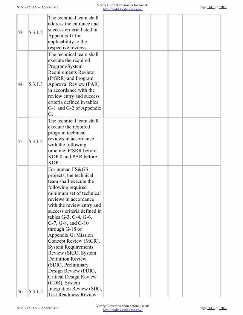
43 5.3.1.2
The technical team shall
address the entrance and
success criteria listed in
Appendix G for
applicability to the
respective reviews.
44 5.3.1.3
The technical team shall
execute the required
Program/System
Requirements Review
(P/SRR) and Program
Approval Review (PAR)
in accordance with the
review entry and success
criteria defined in tables
G-1 and G-2 of Appendix
G.
45 5.3.1.4
The technical team shall
execute the required
program technical
reviews in accordance
with the following
timeline: P/SRR before
KDP 0 and PAR before
KDP 1.
46 5.3.1.5
For human FS&GS
projects, the technical
team shall execute the
following required
minimum set of technical
reviews in accordance
with the review entry and
success criteria defined in
tables G-3, G-4, G-6,
G-7, G-8, and G-10
through G-18 of
Appendix G: Mission
Concept Review (MCR),
System Requirements
Review (SRR), System
Definition Review
(SDR), Preliminary
Design Review (PDR),
Critical Design Review
(CDR), System
Integration Review (SIR),
Test Readiness Review
NPR 7123.1A -- AppendixHVerify Current version before use at:
http://nodis3.gsfc.nasa.gov/Page 147 of 202
NPR 7123.1A -- AppendixHVerify Current version befor use at:
http://nodis3.gsfc.nasa.gov/Page 147 of 202

(TRR), System
Acceptance Review
(SAR), Operational
Readiness Review
(ORR), Flight Readiness
Review (FRR),
Post-Launch Assessment
Review (PLAR), Critical
Event Readiness Review
(CERR), Post-Flight
Assessment Review
(PFAR), and
Decommissioning
Review (DR). (For more
information on program
and project life cycles
and management
reviews, see the
appropriate NPR, e.g.,
NPR 7120.5.)
47 5.3.1.6
For robotic FS&GS
projects, the technical
team shall execute and
document the following
minimum required
technical reviews: the
MCR, SRR, Mission
Definition Review
(MDR), PDR, CDR, SIR,
TRR, ORR, FRR, PLAR,
CERR, and DR in
accordance with the
review entry and success
criteria given in tables
G-3, G-4, G-5, G-7, G-8,
G-10, G-11, G-13
through G-16, and G-18
of Appendix G. Robotic
projects can combine the
SRR and MDR based on
size and level of risk. If
the two reviews are
conducted separately,
Table G-4 will be used
for the SRR and Table
G-5 will be used for the
MDR. If the two reviews
are combined, the
NPR 7123.1A -- AppendixHVerify Current version before use at:
http://nodis3.gsfc.nasa.gov/Page 148 of 202
NPR 7123.1A -- AppendixHVerify Current version befor use at:
http://nodis3.gsfc.nasa.gov/Page 148 of 202

are combined, the
entrance and success
criteria for both SRR and
MDR will be combined
for this single review.
48 5.3.1.7
The technical team shall
also execute a Production
Readiness Review (PRR)
as an additional technical
review for both human
and robotic FS&GS
projects developing or
acquiring multiple or
similar systems greater
than three (or as
determined by the
project) in accordance
with the review entry and
success criteria defined in
Table G-9 of Appendix
G. Any project producing
end products with three
or less units will still
perform the required
CDR. The CDR will
include production
considerations when a
PRR is not performed.
The technical team shall
execute the required
FS&GS project technical
reviews in accordance
with the following
timelines:
a. MCR prior to KDP
A.
b. Human FS&GS
project SRR prior to
SDR, and robotic
missions SRR and MDR
prior to KDP B.
c. Human FS&GS
project SDR prior to
KDP B.
d. PDR prior to KDP
NPR 7123.1A -- AppendixHVerify Current version before use at:
http://nodis3.gsfc.nasa.gov/Page 149 of 202
NPR 7123.1A -- AppendixHVerify Current version befor use at:
http://nodis3.gsfc.nasa.gov/Page 149 of 202

49 5.3.1.8
C.
e. CDR prior to
starting fabrication of
system end products and
SIR.
f. PRR prior to
starting fabrication of
system end products for
projects requiring
multiple units.
g. SIR prior to KDP
D.
h. TRR prior to
starting product
verification and product
validation testing.
i. Human FS&GS
project SAR after
completion of KDP D.
j. ORR after SAR or
KDP D and before FRR.
k. FRR prior to KDP
E.
l. PLAR after system
end product launch.
m. CERR after PLAR
and before KDP F.
n. Human FS&GS
project PFAR at end of
flight and before KDP F.
o. DR after KDP F.
50 5.3.1.9
The assigned technical
team shall accomplish the
monitoring function for
flight-related ATD
projects using
appropriately defined and
conducted periodic
technical reviews (PTR)
and continuation reviews
(CRs). (See Figure 5-3.)
NPR 7123.1A -- AppendixHVerify Current version before use at:
http://nodis3.gsfc.nasa.gov/Page 150 of 202
NPR 7123.1A -- AppendixHVerify Current version befor use at:
http://nodis3.gsfc.nasa.gov/Page 150 of 202

51 5.3.1.10
The assigned technical
team shall accomplish the
monitoring function for
IPs using PTR and SAR.
(See Figure 5-3.)
52 6.2.1
Working with the
program/project manager,
the technical team shall
determine the appropriate
level within the system
structure at which
SEMPs are developed,
taking into account
factors such as number
and complexity of
interfaces, operating
environments, and risk
factors.
53 6.2.2
The technical team shall
baseline the SEMP per
the Center's
Implementation Plan,
incorporating the content
contained in Appendix D,
Systems Engineering
Management Plan, prior
to completion of Phase A
in the program life cycle
or the equivalent
milestone.
54 6.2.3
The DGA shall review
and approve or
disapprove the SEMP at
each major milestone
review or its equivalent.
55 6.2.4
The assigned technical
team shall establish the
initial SEMP early in the
Formulation phase and
update it as necessary to
reflect changes in scope
or improved technical
development.
NPR 7123.1A -- AppendixHVerify Current version before use at:
http://nodis3.gsfc.nasa.gov/Page 151 of 202
NPR 7123.1A -- AppendixHVerify Current version befor use at:
http://nodis3.gsfc.nasa.gov/Page 151 of 202

56 6.2.5
The technical team shall
ensure that any technical
and discipline plans
describe how the
technical activities
covered in the plans are
consistent with the SEMP
and are accomplished as
fully integrated parts of
the technical effort.
57 6.2.6
The technical team shall
ensure that the project's
software development/
management plan
describes how the
software activities are
consistent with the SEMP
and are accomplished as
fully integrated parts of
the technical effort.
3.3 Plan to close gaps
This section would include textual descriptions about how the gaps noted in the matrix will beclosed.
4.0 Other
NPR 7123.1A -- AppendixHVerify Current version before use at:
http://nodis3.gsfc.nasa.gov/Page 152 of 202
NPR 7123.1A -- AppendixHVerify Current version befor use at:
http://nodis3.gsfc.nasa.gov/Page 152 of 202

H-2 SE NPR Center Survey
SE NPR Center Survey
<Center Name>
NPR 7123.1A -- AppendixHVerify Current version before use at:
http://nodis3.gsfc.nasa.gov/Page 153 of 202
NPR 7123.1A -- AppendixHVerify Current version befor use at:
http://nodis3.gsfc.nasa.gov/Page 153 of 202

Revision: <enter rev number>
<enter date>
National Aeronautics and Space Administration
SE NPR Center Survey
<Center>
<Date>
Prepared by:
NPR 7123.1A -- AppendixHVerify Current version before use at:
http://nodis3.gsfc.nasa.gov/Page 154 of 202
NPR 7123.1A -- AppendixHVerify Current version befor use at:
http://nodis3.gsfc.nasa.gov/Page 154 of 202

Name Date
Approved by:
Name
Date
Name
Date
Change Record
Rev. Date Originator Approvals Description
NPR 7123.1A -- AppendixHVerify Current version before use at:
http://nodis3.gsfc.nasa.gov/Page 155 of 202
NPR 7123.1A -- AppendixHVerify Current version befor use at:
http://nodis3.gsfc.nasa.gov/Page 155 of 202

Table of Contents
1.0 Introduction
1.1 purpose
1.2 Scope
1.3 Background
2.0 Applicable Documents
3.0 Planned Activities
3.1 Description of Center-Equivalent Activities
3.2 Traceability Matrix
3.3 Plan to Close Gaps
4.0 Lessons Learned
5.0 Center Best Practices
6.0 Other
Appendix A Acronyms
Appendix B Glossary
Table of Figures
Table of Tables
NPR 7123.1A -- AppendixHVerify Current version before use at:
http://nodis3.gsfc.nasa.gov/Page 156 of 202
NPR 7123.1A -- AppendixHVerify Current version befor use at:
http://nodis3.gsfc.nasa.gov/Page 156 of 202

Table 3-1 Traceability Matrix
1.0 Introduction
1.1 purpose
This document presents the organization's survey for implementing the best practice activities asdescribed in Appendix C of the System Engineering NPR.
1.2 Scope
The scope of this document contains the plan and traceability for implementing the best practiceactivities .
1.3 Background
Describe basic product lines for the Center and the scope of application of NPR activities.
2.0 Reference Documents
List documents such as existing Center requirement documents or work instructions that reflectimplementation of the NPR activities.
3.0 Planned Activities
3.1 Description of Center-Equivalent Activities
This section would include general textual descriptions on the activities used to accomplish theprocesses at the Center.
3.2 Traceability Matrix
Table 3-1 provides the cross-reference of the expected process activities listed in Appendix C of the
NPR 7123.1A -- AppendixHVerify Current version before use at:
http://nodis3.gsfc.nasa.gov/Page 157 of 202
NPR 7123.1A -- AppendixHVerify Current version befor use at:
http://nodis3.gsfc.nasa.gov/Page 157 of 202

SE NPR with equivalent activities in or planned for Center documentation .
Table 3-1 Process Activity Traceability Matrix
No. NPR Process Expected Process
Activities
Center Implementation
Center
Document(s)/
Section/ Task
Fully
In-cluded
Partial-ly
In-cluded
Gap Plan to
close gap
1 Stakeholder
Expecta-tions
Definition
Process
a). Establish a list that
identifies customers and
other stakeholders that
have an interest in the
system and its products.
Example:
JPR 7120.3,
Section xxx
x Update
section
b). Elicit customer and
other stakeholder
expectations (needs,
wants, desires,
capabilities, external
interfaces, and
constraints) from the
identified stakeholders.
None X Create a
new work
instruction
c). Establish operational
concepts and support
strategies based on
stakeholders' expected
use of the system
products over the
system's life.
JPR 7120.3,
Section xxx
x
d). Define stakeholder
expectations in
acceptable statements
that are complete
sentences and have the
following
characteristics: (1)
individually clear,
correct, and feasible to
satisfy; not stated as to
how it is to be satisfied;
implementable; only
one interpretation of
meaning; one
actor-verb-object
expectation; and can be
validated at the level of
JPR 7120.3,
Section xxx
X None
NPR 7123.1A -- AppendixHVerify Current version before use at:
http://nodis3.gsfc.nasa.gov/Page 158 of 202
NPR 7123.1A -- AppendixHVerify Current version befor use at:
http://nodis3.gsfc.nasa.gov/Page 158 of 202
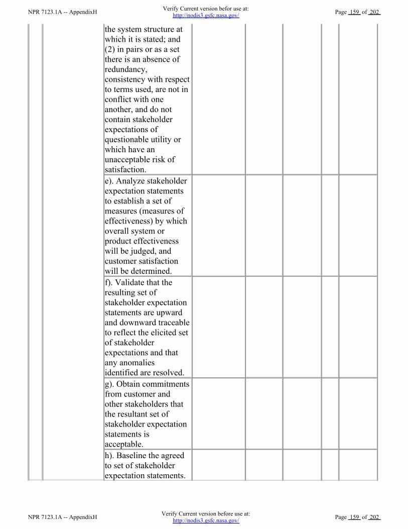
the system structure at
which it is stated; and
(2) in pairs or as a set
there is an absence of
redundancy,
consistency with respect
to terms used, are not in
conflict with one
another, and do not
contain stakeholder
expectations of
questionable utility or
which have an
unacceptable risk of
satisfaction.
e). Analyze stakeholder
expectation statements
to establish a set of
measures (measures of
effectiveness) by which
overall system or
product effectiveness
will be judged, and
customer satisfaction
will be determined.
f). Validate that the
resulting set of
stakeholder expectation
statements are upward
and downward traceable
to reflect the elicited set
of stakeholder
expectations and that
any anomalies
identified are resolved.
g). Obtain commitments
from customer and
other stakeholders that
the resultant set of
stakeholder expectation
statements is
acceptable.
h). Baseline the agreed
to set of stakeholder
expectation statements.
NPR 7123.1A -- AppendixHVerify Current version before use at:
http://nodis3.gsfc.nasa.gov/Page 159 of 202
NPR 7123.1A -- AppendixHVerify Current version befor use at:
http://nodis3.gsfc.nasa.gov/Page 159 of 202

2 Technical
Require-ments
Definition
Process
a). Analyze the scope of
the technical problem to
be solved to identify
and resolve the design
boundary that identifies:
(1) which system
functions are under
design control and
which are not; (2)
expected interaction
among system functions
(data flows, human
responses, and
behaviors); (3) external
physical and functional
interfaces (mechanical,
electrical, thermal, data,
procedural) with other
systems; (4) required
capacities of system
products; (5) timing of
events, states, modes,
and functions related to
operational scenarios;
and (6) emerging or
maturing technologies
necessary to make
requirements.
b). Define constraints
affecting the design of
the system or products
or how the system or
products will be able to
be used.
c). Define functional
and behavioral
expectations for the
system or product in
acceptable technical
terms for the range of
anticipated uses of
system products as
identified in the concept
of operations; this
permits separating
defined stakeholder
expectation functions
NPR 7123.1A -- AppendixHVerify Current version before use at:
http://nodis3.gsfc.nasa.gov/Page 160 of 202
NPR 7123.1A -- AppendixHVerify Current version befor use at:
http://nodis3.gsfc.nasa.gov/Page 160 of 202

and behaviors that
belong to a lower level
in the system structure
and allocating them to
the appropriate level.
d). Define the
performance
requirements associated
with each defined
functional and
behavioral expectation.
e). Define technical
requirements in
acceptable "shall"
statements that are
complete sentences with
a single "shall" per
numbered statement and
have the following
characteristics: (1)
individually clear,
correct, and feasible;
not stated as to how it is
to be satisfied;
implementable; only
one interpretation of
meaning; one
actor-verb-object
requirement; and can be
validated at the level of
the system structure at
which it is stated; and
(2) in pairs or as a set,
there is an absence of
redundancy,
consistency with terms
used, no conflict with
one another, and form a
set of "design-to"
requirements.
f). Validate that the
resulting technical
requirement statements:
(1) have bidirectional
traceability to the
baselined stakeholder
expectations; (2) were
NPR 7123.1A -- AppendixHVerify Current version before use at:
http://nodis3.gsfc.nasa.gov/Page 161 of 202
NPR 7123.1A -- AppendixHVerify Current version befor use at:
http://nodis3.gsfc.nasa.gov/Page 161 of 202

formed using valid
assumptions; and (3) are
essential to and
consistent with
designing and realizing
the appropriate product
solution form that will
satisfy the applicable
product-line life-cycle
phase exit criteria.
g). Define MOPs for
each identified measure
of effectiveness (MOE)
that cannot be directly
used as a design-to
technical requirement.
h). Define appropriate
TPMs by which
technical progress will
be assessed.
i). Establish the
technical requirements
baseline.
3 Logical
Decomposi-tion
Process
a). Define one or more
logical decomposition
models based on the
defined technical
requirements to gain a
more detailed
understanding and
definition of the design
problem to be solved.
b). Allocate the
technical requirements
to the logical
decomposition models
to form a set of derived
technical requirement
statements that have the
following
characteristics:
(1) describe functional
and performance,
service and attribute,
time, and data flow
requirements, etc., as
NPR 7123.1A -- AppendixHVerify Current version before use at:
http://nodis3.gsfc.nasa.gov/Page 162 of 202
NPR 7123.1A -- AppendixHVerify Current version befor use at:
http://nodis3.gsfc.nasa.gov/Page 162 of 202

appropriate for the
selected set of logical
decomposition models;
(2) individually are
complete sentences and
are clear, correct, and
feasible; not stated as to
how to be satisfied;
implementable; only
have one interpretation
of meaning, one
actor-verb-object
expectation; and can be
validated at the level of
the system structure at
which it is stated;
(3) in pairs or as a set,
have an absence of
redundancy, are
adequately related with
respect to terms used,
and are not in conflict
with one another; and
(4) form a set of
detailed "design-to"
requirements.
c). Resolve derived
technical requirement
conflicts.
d). Validate that the
resulting set of derived
technical requirements
have: (1) bidirectional
traceability with the set
of validated technical
requirements and (2)
assumptions and
decision rationales
consistent with the
source set of technical
requirements.
e). Establish the derived
technical requirements
baseline.
NPR 7123.1A -- AppendixHVerify Current version before use at:
http://nodis3.gsfc.nasa.gov/Page 163 of 202
NPR 7123.1A -- AppendixHVerify Current version befor use at:
http://nodis3.gsfc.nasa.gov/Page 163 of 202

4 Design Solution
Definition
Process
a). Define alternative
solutions for the system
end product being
developed or improved
that are consistent with
derived technical
requirements and
nonallocated technical
requirements, if any.
b). Analyze each
alternative solution
against defined criteria,
such as satisfaction of
external interface
requirements;
technology
requirements;
off-the-shelf availability
of products; physical
failure modes, effects,
and criticality;
life-cycle cost and
support considerations;
capacity to evolve;
make vs. buy;
standardization of
products; integration
concerns; and context
of use issues of
operators considering
tasks, location,
workplace equipment,
and ambient conditions.
c). Select the best
solution alternative
based on the analysis
results of each
alternative solution and
technical decision
analysis
recommendations.
d). Generate the full
design description of
the selected alternative
solution in a form
appropriate to the
product-line life-cycle
NPR 7123.1A -- AppendixHVerify Current version before use at:
http://nodis3.gsfc.nasa.gov/Page 164 of 202
NPR 7123.1A -- AppendixHVerify Current version befor use at:
http://nodis3.gsfc.nasa.gov/Page 164 of 202

phase, location of the
WBS model in the
system structure, and
phase exit criteria to
include: (1) system
specification and
external interface
specifications; (2) end
product specifications,
configuration
description documents,
and interface
specifications; (3) end
product subsystem
initial specifications, if
subsystems are
required; (4)
requirements for
associated supporting
enabling products; (5)
end product verification
plan; (6) end product
validation plan; and (7)
applicable logistics and
operate-to procedures.
e). Verify that the
design solution
definition: (1) is
realizable within
constraints imposed on
the technical effort; (2)
has specified
requirements that are
stated in acceptable
statements and have
bidirectional
traceability with the
derived technical
requirements, technical
requirements, and
stakeholder
expectations; and (3)
has decisions and
assumptions made in
forming the solution
consistent with its set of
derived technical
requirements, separately
NPR 7123.1A -- AppendixHVerify Current version before use at:
http://nodis3.gsfc.nasa.gov/Page 165 of 202
NPR 7123.1A -- AppendixHVerify Current version befor use at:
http://nodis3.gsfc.nasa.gov/Page 165 of 202

requirements, separately
allocated technical
requirements, and
identified system
product and service
constraints.
f). Baseline the design
solution definition
specified requirements
including the
specifications and
configuration
descriptions.
g). Initiate development
or acquisition of the
life-cycle supporting
enabling products
needed, as applicable,
for research,
development,
fabrication, integration,
test, deployment,
operations, sustainment,
and disposal.
h). Initiate development
of the system products
of the next lower level
WBS model, if any.
5 Product
Implementa-tion
Process
a). Prepare to conduct
product implementation
including: (1) prepare a
product implementation
strategy and detailed
planning and
procedures and (2)
determine whether the
product configuration
documentation is
adequately complete to
conduct the type of
product implementation
as applicable for the
product-line life-cycle
phase, location of the
product in the system
structure, and phase exit
criteria.
NPR 7123.1A -- AppendixHVerify Current version before use at:
http://nodis3.gsfc.nasa.gov/Page 166 of 202
NPR 7123.1A -- AppendixHVerify Current version befor use at:
http://nodis3.gsfc.nasa.gov/Page 166 of 202

b). If the strategy is for
buying an existing
product, participate in
the buy of the product
including: (1) review
the technical
information made
available by vendors;
(2) assist the preparation
of requests for acquiring
the product from a
vendor; (3) assist the
inspection of the
delivered product and
the accompanying
documentation; (4)
determine whether the
vendor conducted
product validation or if
it will need to be done
by a project technical
team; and (5) determine
the availability of
enabling products to
provide test, operations,
and maintenance
support and disposal
services for the product.
c). If the strategy is to
reuse a product that
exists in the
Government inventory,
participate in acquiring
the reused product
including: (1) review
the technical
information made
available for the
specified product to be
reused; (2) determine
supporting
documentation and user
manuals availability; (3)
determine the
availability of enabling
products to provide test,
operations, and
NPR 7123.1A -- AppendixHVerify Current version before use at:
http://nodis3.gsfc.nasa.gov/Page 167 of 202
NPR 7123.1A -- AppendixHVerify Current version befor use at:
http://nodis3.gsfc.nasa.gov/Page 167 of 202

operations, and
maintenance support
and disposal services
for the product; (4)
assist the requests for
acquiring the product
from Government
sources; and (5) assist
the inspection of the
delivered product and
the accompanying
documentation.
d). If the strategy is to
make the product, (1)
evaluate the readiness
of the product
implementation
enabling products to
make the product, (2)
make the specified
product in accordance
with the specified
requirements,
configuration
documentation, and
applicable standards,
and (3) prepare
appropriate product
support documentation,
such as integration
constraints and/or
special procedures for
performing product
verification and product
validation.
e). Capture work
products and related
information generated
while performing the
product implementation
process activities.
6 Product
Integration
Process
a). Prepare to conduct
product integration to
include: (1) preparing a
product integration
strategy, detailed
planning for the
NPR 7123.1A -- AppendixHVerify Current version before use at:
http://nodis3.gsfc.nasa.gov/Page 168 of 202
NPR 7123.1A -- AppendixHVerify Current version befor use at:
http://nodis3.gsfc.nasa.gov/Page 168 of 202

integration, and
integration sequences
and procedures; and (2)
determining whether the
product configuration
documentation is
adequately complete to
conduct the type of
product integration
applicable for the
product-line life-cycle
phase, location of the
product in the system
structure, and
management phase exit
criteria.
b). Obtain lower level
products required to
assemble and integrate
into the desired product.
c). Confirm that the
received products that
are to be assembled and
integrated have been
validated to
demonstrate that the
individual products
satisfy the agreed upon
set of stakeholder
expectations, including
interface requirements.
d). Prepare the
integration environment
in which assembly and
integration will take
place to include
evaluating the readiness
of the
product-integration
enabling products and
the assigned workforce.
e). Assemble and
integrate the received
products into the
desired end product in
accordance with the
specified requirements,
NPR 7123.1A -- AppendixHVerify Current version before use at:
http://nodis3.gsfc.nasa.gov/Page 169 of 202
NPR 7123.1A -- AppendixHVerify Current version befor use at:
http://nodis3.gsfc.nasa.gov/Page 169 of 202

configuration
documentation,
interface requirements,
applicable standards,
and integration
sequencing and
procedures.
f). Prepare appropriate
product support
documentation, such as
special procedures for
performing product
verification and product
validation.
g). Capture work
products and related
information generated
while performing the
product integration
process activities.
7
Product
Verification
Process
a). Prepare to conduct
product verification to
include as applicable to
the product-line
life-cycle phase and
WBS model location in
the system structure: (1)
reviewing the product
verification plan for
specific procedures,
constraints, conditions
under which
verification will take
place, pre- and
post-verification
actions, and criteria for
determining the success
or failure of verification
methods and
procedures; (2)
arranging the needed
product-verification
enabling products and
support resources; (3)
obtaining the end
product to be verified;
(4) obtaining the
NPR 7123.1A -- AppendixHVerify Current version before use at:
http://nodis3.gsfc.nasa.gov/Page 170 of 202
NPR 7123.1A -- AppendixHVerify Current version befor use at:
http://nodis3.gsfc.nasa.gov/Page 170 of 202

specification and
configuration baseline
against which the
verification is to be
made; and (5)
establishing and
checking the
verification
environment to ensure
readiness for
performing the
verification.
b). Perform the product
verification in
accordance with the
product verification
plan and defined
procedures to collect
data on each specified
requirement with
specific attention given
to MOPs.
c). Analyze the
outcomes of the product
verification, including
identifying verification
anomalies, establishing
recommended
corrective actions, and
establishing
conformance to each
specified requirement
under controlled
conditions.
d). Prepare a product
verification report
providing the evidence
of product conformance
with the applicable
design solution
definition specified
requirements baseline to
which the product was
generated, including
bidirectional
requirements
traceability and actions
NPR 7123.1A -- AppendixHVerify Current version before use at:
http://nodis3.gsfc.nasa.gov/Page 171 of 202
NPR 7123.1A -- AppendixHVerify Current version befor use at:
http://nodis3.gsfc.nasa.gov/Page 171 of 202

taken to correct
anomalies of
verification results.
e). Capture the work
products from the
product verification.
8
Product
Validation
Process
a). Prepare to conduct
product validation to
include as applicable to
the product-line
life-cycle phase and
product location in the
system structure: (1)
reviewing the product
validation plan for
specific procedures,
constraints, conditions
under which validation
will take place, pre- and
post-validation actions,
and criteria for
determining the success
or failure of validation
methods and
procedures; (2)
arranging the needed
product-validation
enabling products and
support resources; (3)
obtaining the end
product to be validated;
(4) obtaining the
stakeholder
expectations baseline
against which the
validation is to be
made; and (5)
establishing and
evaluating the
validation environment
to ensure readiness for
performing the
validation.
NPR 7123.1A -- AppendixHVerify Current version before use at:
http://nodis3.gsfc.nasa.gov/Page 172 of 202
NPR 7123.1A -- AppendixHVerify Current version befor use at:
http://nodis3.gsfc.nasa.gov/Page 172 of 202

b). Perform the product
validation in accordance
with the product
validation plan and
defined procedures to
collect data on
performance of the
product against
stakeholder
expectations with
specific attention given
to MOEs.
c). Analyze the
outcomes of the product
validation to include
identification of
validation anomalies,
establishing
recommended
corrective actions, and
establishing
conformance to
stakeholder
expectations under
operational conditions
(actual, analyzed, or
simulated).
d). Prepare a product
validation report
providing the evidence
of product conformance
with the stakeholder
expectations baseline,
including corrective
actions taken to correct
anomalies of validation
results.
e). Capture the work
products from the
product validation.
9
Product
Transition
Process
a). Prepare to conduct
product transition to
include: (1) preparing a
product implementation
strategy to establish the
type of product
transition to be made (to
NPR 7123.1A -- AppendixHVerify Current version before use at:
http://nodis3.gsfc.nasa.gov/Page 173 of 202
NPR 7123.1A -- AppendixHVerify Current version befor use at:
http://nodis3.gsfc.nasa.gov/Page 173 of 202

the next higher level
customer for product
integration or to an end
user); and (2) reviewing
related end product
stakeholder
expectations and design
solution definition
specified requirements
to identify special
transition procedures
and enabling product
needs for the type of
product transition, if
any, for packaging,
storage, handling,
shipping/transporting,
site preparation,
installation, or
sustainment.
b). Evaluate the end
product, personnel, and
enabling product
readiness for product
transition including: (1)
availability and
appropriateness of the
documentation that will
be packaged and
shipped with the end
product; (2) adequacy
of procedures for
conducting product
transition; (3)
availability and skills of
personnel to conduct
product transition; and
(4) availability of
packaging
materials/containers,
handling equipment,
storage facilities, and
shipping/transporter
services.
NPR 7123.1A -- AppendixHVerify Current version before use at:
http://nodis3.gsfc.nasa.gov/Page 174 of 202
NPR 7123.1A -- AppendixHVerify Current version befor use at:
http://nodis3.gsfc.nasa.gov/Page 174 of 202

c). Prepare the end
product for transition to
include the packaging
and moving the product
to the
shipping/transporting
location and any
intermediate storage.
d). Transition the end
product with required
documentation to the
customer, based on the
type of transition
required, e.g., to the
next higher level WBS
model for product
integration or to the end
user.
e). Prepare sites, as
required, where the end
product will be stored,
assembled, integrated,
installed, used, or
maintained, as
appropriate for the
life-cycle phase,
position of the end
product in the system
structure, and customer
agreement.
f). Capture work
products from product
transition process
activities.
10 Technical
Planning Process
a). Prepare to conduct
technical planning to
include: (1) preparing or
updating a planning
strategy for each of the
common technical
processes of this SE
NPR and (2)
determining: (a)
deliverable work
products from technical
efforts, (b) technical
reporting requirements,
NPR 7123.1A -- AppendixHVerify Current version before use at:
http://nodis3.gsfc.nasa.gov/Page 175 of 202
NPR 7123.1A -- AppendixHVerify Current version befor use at:
http://nodis3.gsfc.nasa.gov/Page 175 of 202

(c) other technical
information needs for
reviews or satisfying
product-line life-cycle
management phase
entry or exit criteria, (d)
product and process
measures to be used in
measuring technical
performance, cost, and
schedule progress, (e)
key or critical technical
events with entry and
success criteria, (f) data
management approach
for data collection and
storage and how
measurement data will
be analyzed, reported,
and dispositioned as
Federal records, (g)
technical risks that need
to be addressed in the
planning effort, (h)
tools and engineering
methods to be
employed in the
technical effort, and (i)
approach to acquiring
and maintaining the
technical expertise
needed (training and
skills development
plan).
b). Define the technical
work to be done to
include associated
technical, support, and
management tasks
needed to generate the
deliverable products
and satisfy entry and
success criteria of key
technical events and the
applicable product-line
life-cycle management
phase.
NPR 7123.1A -- AppendixHVerify Current version before use at:
http://nodis3.gsfc.nasa.gov/Page 176 of 202
NPR 7123.1A -- AppendixHVerify Current version befor use at:
http://nodis3.gsfc.nasa.gov/Page 176 of 202

c). Schedule, organize,
and determine the cost
of the technical effort.
d). Prepare the SEMP
and other technical
plans needed to support
the technical effort and
perform the technical
processes.
e). Obtain stakeholder
commitments to the
technical plans.
f). Issue authorized
technical work
directives to implement
the technical work.
g). Capture work
products from technical
planning activities.
11
Require-ments
Manage-ment
Process
a). Prepare to conduct
requirements
management to include:
(1) preparing or
updating a strategy and
procedures for: (a)
establishing that
expectation and
requirement statements,
singularly and as a
whole, are prepared in
accordance with
established formats and
rules; (b) identifying
expectations and
requirements to be
managed, expectation
and requirement
sources, and allocation
and traceability of
requirements and
linking product
expectations and
requirements with costs,
weight, and power
allocations, as
applicable; and (c)
formal initiation,
NPR 7123.1A -- AppendixHVerify Current version before use at:
http://nodis3.gsfc.nasa.gov/Page 177 of 202
NPR 7123.1A -- AppendixHVerify Current version befor use at:
http://nodis3.gsfc.nasa.gov/Page 177 of 202

assessment, review,
approval, and
disposition of
engineering change
proposals and changes
to expectation and
requirements baseline;
(2) selecting or updating
an appropriate
requirements
management tool; and
(3) training technical
team members in the
established
requirements
management procedures
and in the use of the
selected/updated
requirements
management tool.
b). Conduct
requirements
management to include:
(1) capturing, storing,
and documenting the
expectations and
requirements; (2)
establishing that
expectation and
requirement statements
are compliant with
format and other
established rules; (3)
confirming each
established
requirements baseline
has been validated; and
(4) identifying and
analyzing
out-of-tolerance
system-critical technical
parameters and
unacceptable validation
and verification results
and proposing
requirement-appropriate
changes to correct
out-of-tolerance
NPR 7123.1A -- AppendixHVerify Current version before use at:
http://nodis3.gsfc.nasa.gov/Page 178 of 202
NPR 7123.1A -- AppendixHVerify Current version befor use at:
http://nodis3.gsfc.nasa.gov/Page 178 of 202

out-of-tolerance
requirements.
c). Conduct expectation
and requirements
traceability to include:
(1) tracking
expectations and
requirements between
baselines, especially
MOEs, MOPs, and
TPMs and (2)
establishing and
maintaining appropriate
requirements
compliance matrixes
that contain the
requirements,
bidirectional
traceability, compliance
status, and any actions
to complete
compliance.
d). Manage expectation
and requirement
changes to include: (1)
reviewing engineering
change proposals
(ECPs) to determine
any changes to
established requirement
baselines; (2)
implementing formal
change procedures for
proposed and identified
expectation or
requirement changes;
and (3) disseminating
the approved change
information.
e). Capture work
products from
requirements
management process
activities to include
maintaining and
reporting information
on the rationale for and
NPR 7123.1A -- AppendixHVerify Current version before use at:
http://nodis3.gsfc.nasa.gov/Page 179 of 202
NPR 7123.1A -- AppendixHVerify Current version befor use at:
http://nodis3.gsfc.nasa.gov/Page 179 of 202

disposition and
implementation of
change actions, current
requirement compliance
status, and expectation
and requirement
baselines.
12
Interface
Manage-ment
Process
a). Prepare or update
interface management
procedures for: (1)
establishing interface
management
responsibilities for
those interfaces that are
part of agreement
boundaries; (2)
maintaining and
controlling identified
internal and external
physical and functional
interfaces; (3) preparing
and maintaining
appropriate physical
and functional interface
specifications or
interface control
documents and
drawings to describe
and control interfaces
external to the system
end product; (4)
identifying interfaces
between system
products (including
humans) and among
configuration
management items; (5)
establishing and
implementing formal
change procedures for
interface evolution; (6)
disseminating the
needed interface
information for
integration into
technical effort
activities and for
external interface
NPR 7123.1A -- AppendixHVerify Current version before use at:
http://nodis3.gsfc.nasa.gov/Page 180 of 202
NPR 7123.1A -- AppendixHVerify Current version befor use at:
http://nodis3.gsfc.nasa.gov/Page 180 of 202

external interface
control; and (7) training
technical teams and
other applicable support
and management
personnel in the
established interface
management
procedures.
b). Conduct interface
management during
system design activities
for each WBS model in
the system structure to
include: (1) integrating
the interface
management activities
with requirements
management activities;
(2) analyzing the
concept of operations to
identify critical
interfaces not included
in the stakeholder set of
expectations; (3)
documenting interfaces
both external and
internal to each WBS
model as the
development of the
system structure
emerges and interfaces
are added and existing
interfaces are changed;
(4) documenting origin,
destination, stimulus,
and special
characteristics of
interfaces; (5)
maintaining the design
solution definition for
internal horizontal and
vertical interfaces
between WBS models
in the system structure;
(6) maintaining
horizontal traceability
of interface
NPR 7123.1A -- AppendixHVerify Current version before use at:
http://nodis3.gsfc.nasa.gov/Page 181 of 202
NPR 7123.1A -- AppendixHVerify Current version befor use at:
http://nodis3.gsfc.nasa.gov/Page 181 of 202

of interface
requirements across
interfaces and capturing
status in the established
requirements
compliance matrix; and
(7) confirming that each
interface control
document or drawing
that is established has
been validated with
parties on both sides of
the interface.
c). Conduct interface
management during
product integration
activities to include: (1)
reviewing product
integration procedures
to ensure that interfaces
are marked to ensure
easy and correct
assembly/connection
with other products; (2)
identifying product
integration planning to
identify interface
discrepancies, if any,
and report to the proper
technical team or
technical manager; (3)
confirming that a
precheck is completed
on all physical
interfaces before
connecting products; (4)
evaluating assembled
products for interface
compatibility; (5)
confirming that product
verification and product
validation
plans/procedures
include confirming
internal and external
interfaces; and (6)
preparing an interface
evaluation report upon
NPR 7123.1A -- AppendixHVerify Current version before use at:
http://nodis3.gsfc.nasa.gov/Page 182 of 202
NPR 7123.1A -- AppendixHVerify Current version befor use at:
http://nodis3.gsfc.nasa.gov/Page 182 of 202

evaluation report upon
completion of
integration, product
verification, and
product validation.
d). Conduct interface
control to include: (1)
managing interface
changes within the
system structure; (2)
identifying and tracking
proposed and directed
changes to interface
specifications and
interface control
documents and
drawings; (3)
confirming that the
vertical and horizontal
interface issues are
analyzed and resolved
when a change affects
products on both sides
of the interface; (4)
controlling traceability
of interface changes
including source of the
change, processing
methods, and approvals;
and (5) disseminating
the approved interface
change information for
integration into
technical efforts at
every level of the
project.
e). Capture work
products from interface
management activities.
13
Technical Risk
Manage-ment
Process
a). Prepare a strategy to
conduct technical risk
management to include:
(1) documenting how
the project risk
management plan will
be implemented in the
technical effort; (2)
NPR 7123.1A -- AppendixHVerify Current version before use at:
http://nodis3.gsfc.nasa.gov/Page 183 of 202
NPR 7123.1A -- AppendixHVerify Current version befor use at:
http://nodis3.gsfc.nasa.gov/Page 183 of 202

planning identification
of technical risk sources
and categories; (3)
identification of
potential technical risks;
(4) characterizing and
prioritizing technical
risks; (5) planning
informed technical
management
(mitigation) actions
should the risk event
occur; (6) tracking
technical risk status
against established
triggers; (7) resolving
technical risk by taking
planned action if
established triggers are
tripped; and (8)
communicating
technical risk status and
mitigation actions
taken, when appropriate.
b). Identify technical
risks to include: (1)
identifying sources of
risk issues related to the
technical effort; (2)
anticipate what could
go wrong in each of the
source areas to create
technical risk issues; (3)
analyzing identified
technical risks for cause
and importance; (4)
preparing clear,
understandable, and
standard form risk
statements; and (5)
coordinating with
relevant stakeholders
associated with each
identified technical
risk.
NPR 7123.1A -- AppendixHVerify Current version before use at:
http://nodis3.gsfc.nasa.gov/Page 184 of 202
NPR 7123.1A -- AppendixHVerify Current version befor use at:
http://nodis3.gsfc.nasa.gov/Page 184 of 202

c). Conduct technical
risk assessment to
include: (1) categorize
the severity of
consequences for each
identified technical risk
in terms of
performance, cost, and
schedule impacts to the
technical effort and
project; (2) analyze the
likelihood and
uncertainties of events
associated with each
technical risk and
quantify (for example,
by probabilities) or
qualify (for example, by
high, moderate, or low)
the probability of
occurrence in
accordance with project
risk management plan
rules; and (3) prioritize
risks for mitigation.
d). Prepare for technical
risk mitigation to
include: (1) selecting
risks for mitigation and
monitoring; (2)
selecting an appropriate
risk-handling approach;
(3) establishing the risk
level or threshold when
risk occurrence
becomes unacceptable
and triggers execution
of a risk mitigation
action plan; (4)
selecting contingency
actions and triggers
should risk mitigation
not work to prevent a
problem occurrence; (5)
preparing risk
mitigation and
contingency action
plans identifying
NPR 7123.1A -- AppendixHVerify Current version before use at:
http://nodis3.gsfc.nasa.gov/Page 185 of 202
NPR 7123.1A -- AppendixHVerify Current version befor use at:
http://nodis3.gsfc.nasa.gov/Page 185 of 202

plans identifying
responsibilities and
authorities.
e). Monitor the status of
each technical risk
periodically to include:
(1) tracking risk status
to determine whether
conditions or situations
have changed so that
risk monitoring is no
longer needed or new
risks have been
discovered; (2)
comparing risk status
and risk thresholds; (3)
reporting risk status to
decision authorities
when a threshold has
been triggered and an
action plan
implemented; (4)
preparing technical risk
status reports as
required by the project
risk management plan;
(5) communicating risk
status during technical
reviews in the form
specified by the project
risk management plan.
f). Implement technical
risk mitigation and
contingency action
plans when the
applicable thresholds
have been triggered to
include: (1) monitoring
the results of the action
plan implemented; (2)
modifying the action
plan as appropriate to
the results of the
actions; (3) continuing
actions until the residual
risk and/or
consequences impacts
NPR 7123.1A -- AppendixHVerify Current version before use at:
http://nodis3.gsfc.nasa.gov/Page 186 of 202
NPR 7123.1A -- AppendixHVerify Current version befor use at:
http://nodis3.gsfc.nasa.gov/Page 186 of 202

are acceptable or
become a problem to be
solved; (4)
communicate to the
project when risks are
beyond the scope of the
technical effort to
control, will affect a
product higher in the
system structure, or
represent a significant
threat to the technical
effort or project
success; (5) preparing
action plan
effectiveness reports as
required by the project
risk management plan;
(6) communicating
action plan
effectiveness during
technical reviews in the
form specified by the
project risk
management plan.
g). Capture work
products from technical
risk management
activities.
14 Configura-tion
Manage-ment
Process
a). Prepare a strategy to
conduct configuration
management for the
system products and
designated work
products to include: (1)
documenting how the
project configuration
management plan, if
any, will be
implemented; (2)
identifying items to be
put under configuration
control; (3) identifying
schema of identifiers to
accurately describe a
configuration item and
its revisions or versions;
NPR 7123.1A -- AppendixHVerify Current version before use at:
http://nodis3.gsfc.nasa.gov/Page 187 of 202
NPR 7123.1A -- AppendixHVerify Current version befor use at:
http://nodis3.gsfc.nasa.gov/Page 187 of 202

(4) controlling changes
to configuration items;
(5) maintaining and
reporting disposition
and implementation of
change actions to
appropriate stakeholders
including technical
teams within the
project; (6) enssuring
that products are in
compliance with
specifications and
configuration
documentation during
reviews and audits; (7)
providing the
appropriate reference
configuration at the
start of each
product-line life-cycle
phase; (8) obtaining
appropriate tools for
configuration
management; and (9)
training appropriate
technical team members
and other technical
support and
management personnel
in the established
configuration
management strategy
and any configuration
management procedures
and tools.
b). Identify baselines to
be under configuration
control to include: (1)
listing of the
configuration items to
control; (2) providing
each configuration item
with a unique identifier;
(3) identifying
acceptance
requirements for each
baseline identified for
NPR 7123.1A -- AppendixHVerify Current version before use at:
http://nodis3.gsfc.nasa.gov/Page 188 of 202
NPR 7123.1A -- AppendixHVerify Current version befor use at:
http://nodis3.gsfc.nasa.gov/Page 188 of 202

baseline identified for
control; (4) identifying
the owner of each
configuration item; and
(5) establishing a
baseline configuration
for each configuration
item.
c). Manage
configuration change
control to include: (1)
establishing change
criteria, procedures, and
responsibilities; (2)
receiving, recording,
and evaluating change
requests; (3) tracking
change requests to
closure; (4) obtaining
appropriate approvals
before implementing a
change; (5)
incorporating approved
changes in appropriate
configuration items; (6)
releasing changed
configuration items for
use; and (7) monitoring
implementation to
determine whether
changes resulted in
unintended effects (e.g.,
have compromised
safety or security of
baseline product).
d). Maintain the status
of configuration
documentation to
include: (1) maintaining
configuration item
description records and
records that verify
readiness of
configuration items for
testing, delivery, or
other related technical
efforts; (2) maintaining
NPR 7123.1A -- AppendixHVerify Current version before use at:
http://nodis3.gsfc.nasa.gov/Page 189 of 202
NPR 7123.1A -- AppendixHVerify Current version befor use at:
http://nodis3.gsfc.nasa.gov/Page 189 of 202

change requests,
disposition action taken,
and history of change
status; (3) maintaining
differences between
successive baselines;
and (4) controlling
access to and release of
configuration baselines.
e). Conduct
configuration audits to
include: (1) auditing
baselines under control
to confirm that the
actual work product
configuration matches
the documented
configuration, the
configuration is in
conformance with
product requirements,
and records of all
change actions are
complete and up to
date; (2) identifying
risks to the technical
effort based on incorrect
documentation,
implementation, or
tracking of changes; (3)
assessing the integrity
of the baselines; (4)
confirming the
completeness and
correctness of the
content of configuration
items with applicable
requirements; (5)
confirming compliance
of configuration items
with applicable
configuration
management standards
and procedures; and (6)
tracking action items to
correct anomalies from
audit to closure.
NPR 7123.1A -- AppendixHVerify Current version before use at:
http://nodis3.gsfc.nasa.gov/Page 190 of 202
NPR 7123.1A -- AppendixHVerify Current version befor use at:
http://nodis3.gsfc.nasa.gov/Page 190 of 202

f). Capture work
products from
configuration
management activities
to include: (1) a list of
identified configuration
items; (2) description of
configuration items
placed under control;
(3) change requests,
disposition of the
requests, and rationale
for the dispositions; (4)
documented changes
with reason for changes
and change actions; (5)
archive of old
baselines; and (6)
required reports on
configuration
management outcomes.
15 Technical Data
Manage-ment
Process
a). Prepare a strategy
for the conduct of
technical data
management to include:
(1) determining
required data content
and form and electronic
data exchange
interfaces in accordance
with international
standards or
agreements; (2)
establishing a
framework for technical
data flow within the
project technical
processes and to/from
contractors; (3)
designating technical
data management
responsibilities and
authorities regarding
origination, generation,
capture, archiving,
security, privacy, and
disposal of technical
data work products; (4)
NPR 7123.1A -- AppendixHVerify Current version before use at:
http://nodis3.gsfc.nasa.gov/Page 191 of 202
NPR 7123.1A -- AppendixHVerify Current version befor use at:
http://nodis3.gsfc.nasa.gov/Page 191 of 202

data work products; (4)
establishing the rights,
obligations and
commitments regarding
the retention of,
transmission of, and
access to technical data
items; (5) establishing
relevant data storage,
transformation,
transmission and
presentation standards
and conventions to be
used; (6) establishing
project or program
policy and agreements
or legislative
constraints; (7)
describing the methods,
tools, and metrics used
during the technical
effort and for technical
data management; and
(8) training appropriate
technical team members
and support and
management personnel
in the established
technical data
management strategy
and related procedures
and tools.
b). Collect and store
required technical data
to include: (1)
identifying existing
sources of technical
data that are designated
as outputs of the
common technical
processes; (2) collecting
and storing technical
data in accordance with
the technical data
management strategy
and procedures; (3)
recording and
distributing lessons
NPR 7123.1A -- AppendixHVerify Current version before use at:
http://nodis3.gsfc.nasa.gov/Page 192 of 202
NPR 7123.1A -- AppendixHVerify Current version befor use at:
http://nodis3.gsfc.nasa.gov/Page 192 of 202

distributing lessons
learned; (4) performing
technical data integrity
checks on collected data
to confirm compliance
with content and format
requirements and
identifying errors in
specifying or recording
data; and (5)
prioritizing, reviewing,
and updating technical
data collection and
storage procedures.
c). Maintain stored
technical data to
include: (1) managing
the databases to
maintain proper quality
and integrity of the
collected and stored
technical data and to
confirm that the
technical data is secure
and is available to those
with authority to have
access; (2) performing
technical data
maintenance as
required; (3) preventing
the stored data from
being used or accessed
inappropriately; (4)
maintaining the stored
technical data in a
manner that protects it
against foreseeable
hazards, such as fire,
flood, earthquake, and
riots; and (5)
maintaining periodic
backups of each
technical database.
NPR 7123.1A -- AppendixHVerify Current version before use at:
http://nodis3.gsfc.nasa.gov/Page 193 of 202
NPR 7123.1A -- AppendixHVerify Current version befor use at:
http://nodis3.gsfc.nasa.gov/Page 193 of 202

d). Provide technical
data to authorized
parties to include: (1)
maintaining an
information library or
reference index to
provide data available
and access instructions;
(2) receiving and
evaluating requests for
technical data and
delivery instructions;
(3) confirming that
required and requested
technical data is
appropriately
distributed to satisfy the
needs of the requesting
party and in accordance
with established
procedures, directives,
and agreements; (4)
confirming that
electronic access rules
are followed before
allowing access to the
database and before any
data is electronically
released/transferred to
the requester; and (5)
providing proof of
correctness, reliability,
and security of technical
data provided to internal
and external recipients.
16
Technical
Assessment
Process
a). Prepare a strategy
for conducting technical
assessments to include:
(1) identifying the plans
against which progress
and achievement of the
technical effort are to be
assessed; (2)
establishing procedures
for obtaining cost
expenditures against
work planned and task
completions against
NPR 7123.1A -- AppendixHVerify Current version before use at:
http://nodis3.gsfc.nasa.gov/Page 194 of 202
NPR 7123.1A -- AppendixHVerify Current version befor use at:
http://nodis3.gsfc.nasa.gov/Page 194 of 202

completions against
schedule; (3) identifying
and obtaining technical
requirements against
which product
development progress
and achievement will be
assessed and
establishing the
procedures for
conducting the
assessments; (4)
establishing events
when TPMs, estimation
or measurement
techniques, and rules
for taking action when
out-of-tolerance
conditions exist will be
assessed; (5) identifying
and planning for
phase-to-phase
technical reviews and
WBS model-to-model
vertical progress
reviews, as well as
establishing review
entry and success
criteria, review board
members, and close out
procedures; (6)
establishing which
technical effort work
products will undergo
peer review, the team
members who will
perform the peer
reviews, and reporting
requirements; and (7)
training team members,
support staff, and
managers involved in
conducting technical
assessment activities.
NPR 7123.1A -- AppendixHVerify Current version before use at:
http://nodis3.gsfc.nasa.gov/Page 195 of 202
NPR 7123.1A -- AppendixHVerify Current version befor use at:
http://nodis3.gsfc.nasa.gov/Page 195 of 202

b). Assess technical
work productivity
(progress and
achievement against
plans) to include: (1)
identifying, collecting,
and analyzing process
measures (e.g., earned
value measurements for
measuring progress
against planned cost,
schedule, resource use,
and technical effort
tasks) and identifying
and reporting
cost-effective changes
to correct variances; (2)
monitoring stakeholder
involvement according
to the SEMP; and (3)
monitoring technical
data management
against plans.
c). Assess product
quality (progress and
achievements against
technical requirements)
to include: (1)
identifying, collecting,
and analyzing the
degree of technical
requirement and TPM
satisfaction; (2)
assessing the maturity
of the WBS-model
products and services as
applicable to the
product-line life-cycle
phases; (3) determining
any variances from
expected values of
product performance
and identifying and
defining cost-effective
changes to correct
variances.
NPR 7123.1A -- AppendixHVerify Current version before use at:
http://nodis3.gsfc.nasa.gov/Page 196 of 202
NPR 7123.1A -- AppendixHVerify Current version befor use at:
http://nodis3.gsfc.nasa.gov/Page 196 of 202

d). Conduct technical
reviews to include: (1)
identifying the type of
technical reviews and
each review's purpose
and objectives (see
Chapter 5 for specific
technical reviews that
apply); (2) determining
progress toward
satisfying entry criteria;
(3) establishing the
makeup of the review
team; (4) preparing the
review presentation
materials; and (5)
identifying and
resolving action items
resulting from the
review.
e). Capture work
products from the
conduct of technical
assessment activities to
include: (1) identifying
variances resulting from
technical assessments;
(2) identifying and
reporting changes to
correct variances; (3)
recording methods used
in doing assessment
activities; (4)
documenting
assumptions made in
arriving at the process
and product measure
outcomes; and (5)
reporting corrective
action
recommendations.
17
Decision
Analysis Process
a). Establish guidelines
to determine which
technical issues are
subject to a formal
analysis/evaluation
process to include: (1)
NPR 7123.1A -- AppendixHVerify Current version before use at:
http://nodis3.gsfc.nasa.gov/Page 197 of 202
NPR 7123.1A -- AppendixHVerify Current version befor use at:
http://nodis3.gsfc.nasa.gov/Page 197 of 202
when to use a formal
decisionmaking
procedure, for example,
as a result of an
effectiveness
assessment, a technical
tradeoff, a problem
needing to be solved,
action needed as a
response to risk
exceeding the
acceptable threshold,
verification or
validation failure,
make-buy choice,
evaluating a solution
alternative, or resolving
a requirements conflict;
(2) what needs to be
documented; (3) who
will be the decision
makers and their
responsibilities and
decision authorities;
and (4) how decisions
will be handled that do
not require a formal
evaluation procedure.
b). Define the criteria
for evaluating
alternative solutions to
include: (1) the types of
criteria to consider
include the following:
technology limitations,
environmental impact,
safety, risks, total
ownership and
life-cycle costs, and
schedule impact; (2) the
acceptable range and
scale of the criteria; and
(3) the rank of each
criterion by its
importance.
NPR 7123.1A -- AppendixHVerify Current version before use at:
http://nodis3.gsfc.nasa.gov/Page 198 of 202
NPR 7123.1A -- AppendixHVerify Current version befor use at:
http://nodis3.gsfc.nasa.gov/Page 198 of 202

c). Identify alternative
solutions to address
decision issues to
include alternatives for
consideration in
addition to those that
may be provided with
the issue.
d). Select evaluation
methods and
tools/techniques based
on the purpose for
analyzing a decision
and on the availability
of the information used
to support the method
and/or tool.
e). Evaluate alternative
solutions with the
established criteria and
selected methods to
include: (1) evaluation
of assumptions related
to evaluation criteria
and of the evidence that
supports the
assumptions; and (2)
evaluation of whether
uncertainty in the values
for alternative solutions
affects the evaluation.
f). Select recommended
solutions from the
alternatives based on
the evaluation criteria to
include documenting
the information that
justifies the
recommendations and
gives the impacts of
taking the
recommended course of
action.
NPR 7123.1A -- AppendixHVerify Current version before use at:
http://nodis3.gsfc.nasa.gov/Page 199 of 202
NPR 7123.1A -- AppendixHVerify Current version befor use at:
http://nodis3.gsfc.nasa.gov/Page 199 of 202

g). Report the
analysis/evaluation
results/findings with
recommendations,
impacts, and corrective
actions.
h). Capture work
products from decision
analysis activities to
include: (1) decision
analysis guidelines
generated and strategy
and procedures used;
(2) analysis/evaluation
approach, criteria, and
methods and tools used;
(3) analysis/evaluation
results, assumptions
made in arriving at
recommendations,
uncertainties and
sensitivities of the
recommended actions
or corrective actions;
and (4) lessons learned
and recommendations
for improving future
decision analyses.
3.3 Plan to close gaps
This section would include textual descriptions about how the gaps noted in the matrix will beclosed.
4.0 Lessons Learned
This section would include any lessons learned during the Center survey that was valuable to theCenter and which might also be useful information for other Centers.
NPR 7123.1A -- AppendixHVerify Current version before use at:
http://nodis3.gsfc.nasa.gov/Page 200 of 202
NPR 7123.1A -- AppendixHVerify Current version befor use at:
http://nodis3.gsfc.nasa.gov/Page 200 of 202

5.0 Center Best Practices
This section would include descriptions of what the Center considers its best practices and whichpractices might be used to update or improve the processes in the SE NPR.
6.0 Other
Any other information that the Center would like to document or pass on.
NPR 7123.1A -- AppendixHVerify Current version before use at:
http://nodis3.gsfc.nasa.gov/Page 201 of 202
NPR 7123.1A -- AppendixHVerify Current version befor use at:
http://nodis3.gsfc.nasa.gov/Page 201 of 202

Appendix I. Additional Reading
The following documents were used as reference materials in the development of this SE NPR. Thedocuments are offered as informational sources and are not evoked in this SE NPR, though they maybe referenced.
1. MIL-STD-499B (draft), Systems Engineering.
2. ISO/IEC 15288, System Life Cycle Processes.
ISO/IEC 15288 defines international system life processes plus for any domain (e.g., transportation,medical, commercial).
3. ANSI/EIA 632, Processes for Engineering a System.
EIA 632 is a commercial document that evolved from the never released, but fully developed, 1994Mil-Std 499B Systems Engineering. It was intended to provide a framework for developing andsupporting universal SE discipline for both defense and commercial environments. EIA 632 wasintended to be a top-tier standard further defined to lower level standards that define specificpractices.
IEEE 1220 is a second-tier standard that implements EIA 632 by defining one way to practicesystems engineering.
4. CMMI model.
The Capability Maturity Model« (CMM) IntegrationSM (CMMI) in its present form is a collectionof best practices for the "development and maintenance" of both "products and services." The modelwas developed by integrating practices from four different CMMs, the "source models" the CMMfor software, for systems engineering, for integrated product development (IPD), and for acquisition.Organizations can use the model to improve their ability to develop (or maintain) products (andservices) on time, within budget, and with desired quality. CMMI also provides these organizationsthe framework for enlarging the focus of process improvement to other areas that also affect productdevelopment, i.e., the discipline of systems engineering. During the past decade, new and effectiveconcepts for organizing developmental work have surfaced and been adopted, such as concurrentengineering or the use of integrated teams. Organizations using (or wishing to adopt these ideas) canalso find support in the CMMI by using the model with integrated product and process development(IPPD) additions.
5. Defense Acquisition University Systems Engineering Fundamentals. Ft. Belvoir, Virginia:Defense Acquisition University Press, December 2000.
6. International Council on Systems Engineering Systems Engineering Guide.
7. ISO/IEC TR 19760, Systems Engineering A Guide for the Application of ISO/IEC 15288(System Life Cycle Processes).
8. AS9100: Quality Management Systems Aerospace Requirements. G-14 Americas AerospaceQuality Group.
NPR 7123.1A -- AppendixIVerify Current version before use at:
http://nodis3.gsfc.nasa.gov/Page 202 of 202
NPR 7123.1A -- AppendixIVerify Current version befor use at:
http://nodis3.gsfc.nasa.gov/Page 202 of 202