Embed Size (px)
Citation preview
PROCEDURAL HANDBOOK
SuperGlaze® 5356 TM™
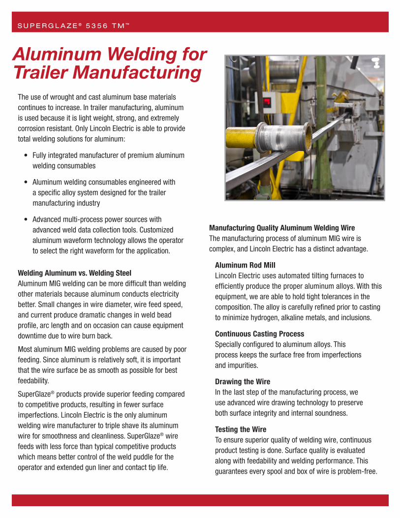
The use of wrought and cast aluminum base materials continues to increase. In trailer manufacturing, aluminum is used because it is light weight, strong, and extremely corrosion resistant. Only Lincoln Electric is able to provide total welding solutions for aluminum:
• Fully integrated manufacturer of premium aluminum welding consumables
• Aluminum welding consumables engineered with a specific alloy system designed for the trailer manufacturing industry
• Advanced multi-process power sources with advanced weld data collection tools. Customized aluminum waveform technology allows the operator to select the right waveform for the application.
Welding Aluminum vs. Welding Steel Aluminum MIG welding can be more difficult than welding other materials because aluminum conducts electricity better. Small changes in wire diameter, wire feed speed, and current produce dramatic changes in weld bead profile, arc length and on occasion can cause equipment downtime due to wire burn back.
Most aluminum MIG welding problems are caused by poor feeding. Since aluminum is relatively soft, it is important that the wire surface be as smooth as possible for best feedability.
SuperGlaze® products provide superior feeding compared to competitive products, resulting in fewer surface imperfections. Lincoln Electric is the only aluminum welding wire manufacturer to triple shave its aluminum wire for smoothness and cleanliness. SuperGlaze® wire feeds with less force than typical competitive products which means better control of the weld puddle for the operator and extended gun liner and contact tip life.
Manufacturing Quality Aluminum Welding Wire The manufacturing process of aluminum MIG wire is complex, and Lincoln Electric has a distinct advantage.
Aluminum Rod Mill Lincoln Electric uses automated tilting furnaces to efficiently produce the proper aluminum alloys. With this equipment, we are able to hold tight tolerances in the composition. The alloy is carefully refined prior to casting to minimize hydrogen, alkaline metals, and inclusions.
Continuous Casting Process Specially configured to aluminum alloys. This process keeps the surface free from imperfections and impurities.
Drawing the Wire In the last step of the manufacturing process, we use advanced wire drawing technology to preserve both surface integrity and internal soundness.
Testing the Wire To ensure superior quality of welding wire, continuous product testing is done. Surface quality is evaluated along with feedability and welding performance. This guarantees every spool and box of wire is problem-free.
Aluminum Welding for Trailer Manufacturing
S U P E R G L A Z E ® 5 3 5 6 T M ™
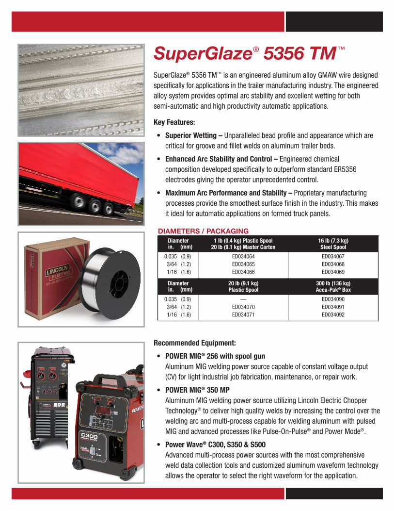
SuperGlaze® 5356 TM™
SuperGlaze® 5356 TM™ is an engineered aluminum alloy GMAW wire designed specifically for applications in the trailer manufacturing industry. The engineered alloy system provides optimal arc stability and excellent wetting for both semi-automatic and high productivity automatic applications.
Key Features:
• Superior Wetting – Unparalleled bead profile and appearance which are critical for groove and fillet welds on aluminum trailer beds.
• Enhanced Arc Stability and Control – Engineered chemical composition developed specifically to outperform standard ER5356 electrodes giving the operator unprecedented control.
• Maximum Arc Performance and Stability – Proprietary manufacturing processes provide the smoothest surface finish in the industry. This makes it ideal for automatic applications on formed truck panels.
Recommended Equipment:
• POWER MIG® 256 with spool gun Aluminum MIG welding power source capable of constant voltage output (CV) for light industrial job fabrication, maintenance, or repair work.
• POWER MIG® 350 MP Aluminum MIG welding power source utilizing Lincoln Electric Chopper Technology® to deliver high quality welds by increasing the control over the welding arc and multi-process capable for welding aluminum with pulsed MIG and advanced processes like Pulse-On-Pulse® and Power Mode®.
• Power Wave® C300, S350 & S500 Advanced multi-process power sources with the most comprehensive weld data collection tools and customized aluminum waveform technology allows the operator to select the right waveform for the application.
DIAMETERS / PACKAGINGDiameter 1 lb (0.4 kg) Plastic Spool
20 lb (9.1 kg) Master Carton16 lb (7.3 kg) Steel Spool in. (mm)
0.0353/641/16
(0.9)(1.2)(1.6)
ED034064ED034065ED034066
ED034067ED034068ED034069
Diameter 20 lb (9.1 kg) Plastic Spool
300 lb (136 kg) Accu-Pak® Box in. (mm)
0.0353/641/16
(0.9)(1.2)(1.6)
—ED034070ED034071
ED034090ED034091ED034092
Lap & Fillet WeldS U P E R G L A Z E ® 5 3 5 6 T M ™
PROCESS: CONSTANT VOLTAGE (CV)
Thicknessin (mm)
WFS
Volts
Amps (approx.)
0.035 in (0.9 mm) Diameter
1/16 (1.6) 250350
1617.5
5575
1/8 (3.2)350450550
20.521.523
110115145
3/16 (4.8)425500600
2224
25.5
124140180
1/4 (6.4)550600700
252728
125170195
3/8 (9.5) 700 28 195
3/64 in (1.2 mm) Diameter
1/16 (1.6) 200 21 80
1/8 (3.2)250350450
2223
23.5
130170205
3/16 (4.8)300400500
22.52324
145180230
1/4 (6.4)350450550
2324
24.5
165200250
3/8 (9.5) 450550650
2425
25.5
200240275
1/16 in (1.6 mm) Diameter
1/8 (3.2) 175225
1919.5
150185
3/16 (4.8)200325350
222524
170250255
1/4 (6.4)250350425
23.524.528
210295305
3/8 (9.5)250350450
242527
195290365
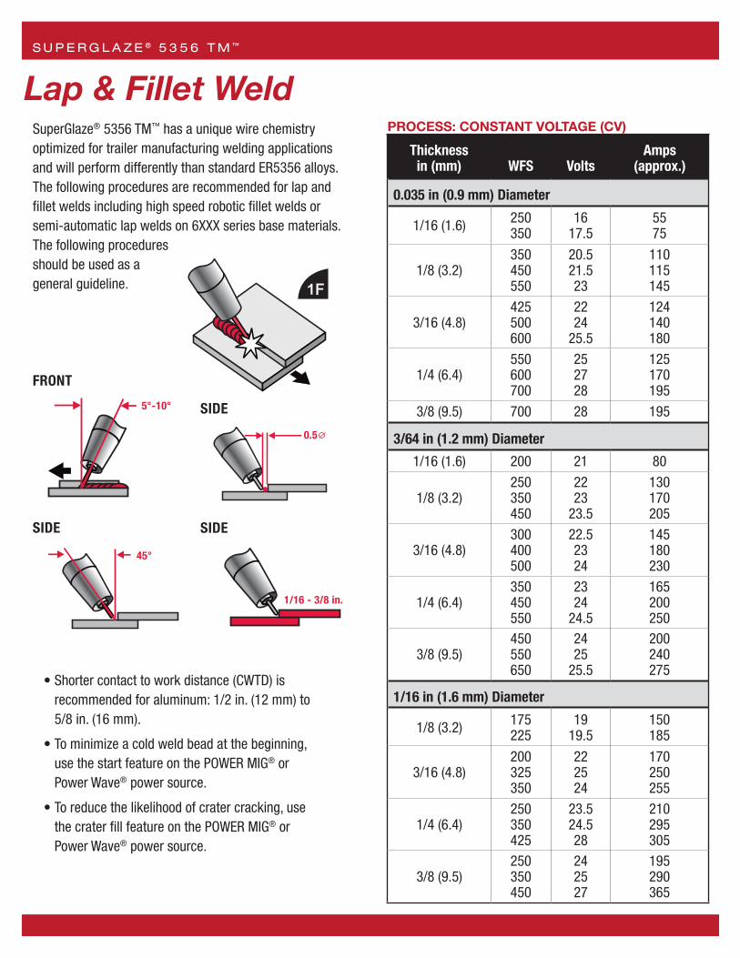
•Shorter contact to work distance (CWTD) is recommended for aluminum: 1/2 in. (12 mm) to 5/8 in. (16 mm).
•To minimize a cold weld bead at the beginning, use the start feature on the POWER MIG® or Power Wave® power source.
•To reduce the likelihood of crater cracking, use the crater fill feature on the POWER MIG® or Power Wave® power source.
SuperGlaze® 5356 TM™ has a unique wire chemistry optimized for trailer manufacturing welding applications and will perform differently than standard ER5356 alloys. The following procedures are recommended for lap and fillet welds including high speed robotic fillet welds or semi-automatic lap welds on 6XXX series base materials. The following procedures should be used as a general guideline.
FRONT
SIDE
SIDESIDE
0.5
5°-10°
45°
1/16 - 3/8 in.
PROCEDURES
PROCESS: PULSE
Thicknessin (mm)
WFS
Trim
Volts
Amps (approx.)
0.035 in (0.9 mm) Diameter
1/16 (1.6) 200300
0.951.00
1818
5070
1/8 (3.2)350400450
1.051.101.10
2020.521
8095
110
3/16 (4.8)525650700
1.101.101.10
232425
130140160
3/64 in (1.2 mm) Diameter
1/16 (1.6)200300400
0.950.950.95
17.519.522
90135175
1/8 (3.2)250400550
0.951.001.00
20.522
24.5
110180260
3/16 (4.8)400500600
0.950.950.95
222324
180220245
1/4 (6.4)350450600
1.001.001.00
21.52324
145200265
3/8 (9.5) 450550650
1.001.001.00
2224
24.5
200220240
1/16 in (1.6 mm) Diameter
1/8 (3.2)200250300
1.001.001.00
19.52122
170205255
3/16 (4.8)200300400
1.001.001.00
19.522
24.5
165245330
1/4 (6.4)200300400
1.101.051.00
20.522.524.5
155225310
3/8 (9.5)300350400
1.001.001.00
2223
24.5
235270320
PROCESS: POWER MODE®
Thicknessin (mm)
WFS
PowerkW/hr
Volts
Amps (approx.)
3/64 in (1.2 mm) Diameter
1/16 (1.6)210250300
2.202.703.40
202023
105130150
1/8 (3.2)250400550
2.804.506.00
242425
130185245
3/16 (4.8)300400500
3.704.505.60
232424
150190215
1/4 (6.4)300450600
3.705.506.60
242424
150205270
3/8 (9.5) 350450550
4.205.006.00
242424
165205230
1/16 in (1.6 mm) Diameter
1/8 (3.2)200300400
4.205.005.60
222222
205240265
3/16 (4.8)200300400
4.205.006.20
182222
205240325
1/4 (6.4)250350450
4.607.009.20
232425
195280370
3/8 (9.5)250350450
4.807.009.30
2324.525.5
205380370
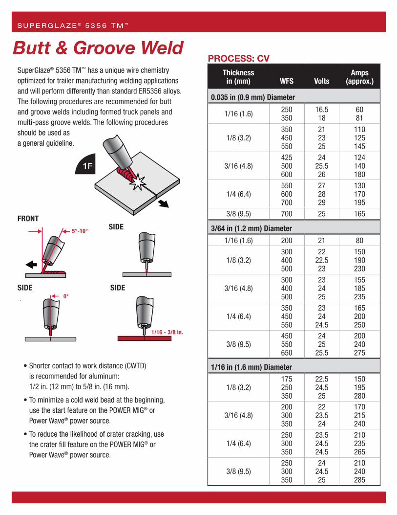
Butt & Groove WeldS U P E R G L A Z E ® 5 3 5 6 T M ™
PROCESS: CV
Thicknessin (mm)
WFS
Volts
Amps (approx.)
0.035 in (0.9 mm) Diameter
1/16 (1.6) 250350
16.518
6081
1/8 (3.2)350450550
212325
110125145
3/16 (4.8)425500600
2425.526
124140180
1/4 (6.4)550600700
272829
130170195
3/8 (9.5) 700 25 165
3/64 in (1.2 mm) Diameter
1/16 (1.6) 200 21 80
1/8 (3.2)300400500
2222.523
150190230
3/16 (4.8)300400500
232425
155185235
1/4 (6.4)350450550
2324
24.5
165200250
3/8 (9.5) 450550650
2425
25.5
200240275
1/16 in (1.6 mm) Diameter
1/8 (3.2)175250350
22.524.525
150195280
3/16 (4.8)200300350
2223.524
170215240
1/4 (6.4)250300350
23.524.524.5
210235265
3/8 (9.5)250300350
2424.525
210240285
•Shorter contact to work distance (CWTD) is recommended for aluminum: 1/2 in. (12 mm) to 5/8 in. (16 mm).
•To minimize a cold weld bead at the beginning, use the start feature on the POWER MIG® or Power Wave® power source.
•To reduce the likelihood of crater cracking, use the crater fill feature on the POWER MIG® or Power Wave® power source.
SuperGlaze® 5356 TM™ has a unique wire chemistry optimized for trailer manufacturing welding applications and will perform differently than standard ER5356 alloys. The following procedures are recommended for butt and groove welds including formed truck panels and multi-pass groove welds. The following procedures should be used as a general guideline.
FRONT
SIDE SIDE
SIDE5°-10°
0°
1/16 - 3/8 in.
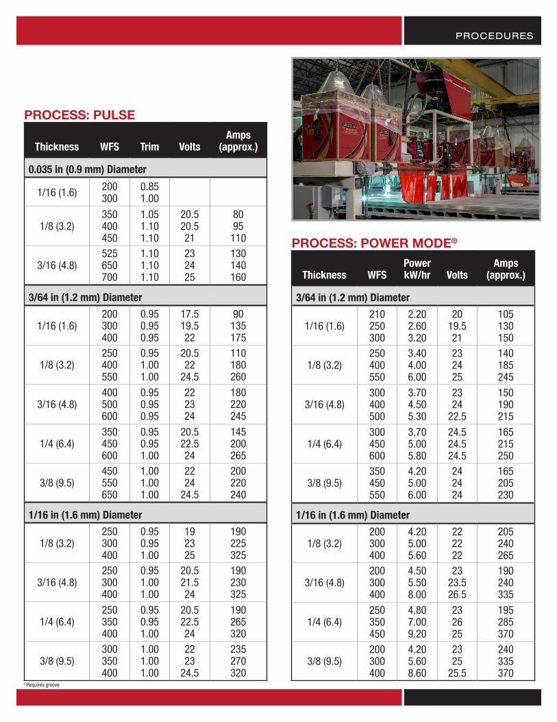
PROCEDURES
PROCESS: PULSE
Thickness
WFS
Trim
Volts
Amps (approx.)
0.035 in (0.9 mm) Diameter
1/16 (1.6) 200300
0.851.00
1/8 (3.2)350400450
1.051.101.10
20.520.521
8095
110
3/16 (4.8)525650700
1.101.101.10
232425
130140160
3/64 in (1.2 mm) Diameter
1/16 (1.6)200300400
0.950.950.95
17.519.522
90135175
1/8 (3.2)250400550
0.951.001.00
20.522
24.5
110180260
3/16 (4.8)400500600
0.950.950.95
222324
180220245
1/4 (6.4)350450600
0.950.951.00
20.522.524
145200265
3/8 (9.5) 450550650
1.001.001.00
2224
24.5
200220240
1/16 in (1.6 mm) Diameter
1/8 (3.2)250300400
0.950.951.00
192325
190225325
3/16 (4.8)250300400
0.951.001.00
20.521.524
190230325
1/4 (6.4)250350400
0.950.951.00
20.522.524
190265320
3/8 (9.5)300350400
1.001.001.00
2223
24.5
235270320
PROCESS: POWER MODE®
Thickness
WFS
PowerkW/hr
Volts
Amps (approx.)
3/64 in (1.2 mm) Diameter
1/16 (1.6)210250300
2.202.603.20
2019.521
105130150
1/8 (3.2)250400550
3.404.006.00
232425
140185245
3/16 (4.8)300400500
3.704.505.30
2324
22.5
150190215
1/4 (6.4)300450600
3.705.005.80
24.524.524.5
165215250
3/8 (9.5) 350450550
4.205.006.00
242424
165205230
1/16 in (1.6 mm) Diameter
1/8 (3.2)200300400
4.205.005.60
222222
205240265
3/16 (4.8)200300400
4.505.508.00
2323.526.5
190240335
1/4 (6.4)250350450
4.807.009.20
232625
195285370
3/8 (9.5)200300400
4.205.608.60
2325
25.5
240335370
(1)Requires groove
TroubleshootingS U P E R G L A Z E ® 5 3 5 6 T M ™
Welding Defects – Causes and Cures Some weld defects — or discontinuities — may be small enough that they don’t seriously impair the mechanical properties of the weld joint. Other discontinuities may cause immediate joint failure. The effects of other discontinuities may be more insidious. It is not the purpose of this section to assess the acceptability or rejectability of specific discontinuities. Instead, the appearance of the various types of weld defects will be illustrated and methods to eliminate or minimize these defects.
CrackingCracking occurs when a combination of a susceptible microstructure or chemistry and a sufficiently high solidification stress are present. If you reduce the stress or change the microstructure or chemistry, the cracking can be eliminated.
All weld cracking in aluminum is caused by hot cracking. That is, it takes place during weld solidification.
CRATER CRACKINGIf the arc is extinguished rapidly, there isn’t enough filler metal present to avoid forming a deep “crater”. The geometry of the crater locally intensifies the solidification stresses. If they are high enough, a crack forms in and around the crater.
In order to eliminate crater cracking, the geometric discontinuity of the crater must be minimized, i.e., the crater must be filled in as much as possible. There are several methods to prevent crater cracking:
• Use a power supply with a crater fill option.
• Rapidly restrike and extinguish the arc a few times while keeping the wire tip in the crater. This will build up the crater.
• Run the weld bead to the end of the workpiece, then reverse direction and increase travel speed in the new travel direction.
LONGITUDINAL CRACKINGLongitudinal cracking occurs relatively frequently.
Weld cracking can usually be eliminated by taking following precautions:
• Heat treatable alloys are crack sensitive and will crack if welded autogenously. Make sure you add filler metal.
• Make sure you add enough filler metal in welding any alloy. Do not deposit thin, concave groove welds or small or concave fillets. They may crack. Weld passes in both groove welds and fillet welds should be slightly convex.
• If cracking is encountered in making a square butt weld, try a V-Groove preparation. It will allow more surface area of the base material to be included in the joint. Similarly, if you’re using a bevel prep, go to a V-prep.
• Reduce the clamping pressure to allow the material to move slightly during solidification. Restraining the part can cause stress on the weld as it cools, solidifies and contracts. Occasionally high stress is caused by the joint geometry, which may need to be changed.
LIQUATION CRACKINGLiquation cracking is common in lap and fillet welds in thin heat- treatable alloys. It usually is not seen in the non heat-treatable alloys or in butt joints. It manifests itself as a short longitudinal crack in the parent material on the back side of a weld. It is caused by the melting of low melting point compounds which tend to segregate to the grain boundaries in heat-treatable alloys.
In order to minimize it, weld penetration into the parent metal needs to be controlled in lap and fillet welds. Welds having 30 or 40% penetration into the parent metal will almost never cause a crack, while welds penetrating 70-80% into the parent metal will often cause a small crack on the back side of a weld.
TROUBLESHOOTING
Incomplete PenetrationIncomplete penetration is often caused by insufficient weld current at a welding travel speed that is too high. However the use of an arc voltage that is too high can also result in the arc bridging the weld root and not penetrating completely.
Care must also be taken in backgouging a two–sided weld. Insufficient backgouging can sometimes result in incomplete penetration. It is sometimes surprising how deep the backgouge must be to get to sound metal.
PorosityPorosity in aluminum welds is caused by bubbles of hydrogen gas which are trapped in the welds as it cools. The source of this hydrogen is oils, greases, or water vapor that is dissociated by the welding arc. In order to control weld porosity, the sources of these contaminates must be eliminated. It is also helpful when welding in the vertical position, to use an upward progression, rather than the downward progression usually used to weld steel, to minimize weld porosity.
Porosity can usually be eliminated by taking the following precautions:
• Remove oils and greases from the surface of the base material.
• Wiping with a clean rag saturated with a degreasing solvent. This method is very effective.
• Mild alkaline solutions make good degreasers. The part to be degreased can be sprayed with these solutions or dipped into a tank containing them. Since such cleaners are usually water based, it is important to thoroughly dry the part after degreasing.
• Acid based cleaning solutions for cleaning aluminum. These are usually effective. However, all are acidic and some contain hydrofluoric acid, so caution in their use and disposal is required. Again, since they contain water, the piece must be thoroughly dried before welding.
• Remove excess oxides.
• Brush lightly with a stainless steel wire brush.
• Oxide removal can also be performed by immersing the part in a strong alkaline solution.
• Interpass cleaning.
• Remove oxides and weld smut (composed largely of aluminum oxide and magnesium oxide) before depositing another pass with a stainless steel wire brush using light pressure.
Copper contamination will also appear white on a radiograph. Copper contamination is usually larger and “fuzzier” than tungsten, which appears as individual small particles.
Copper contamination is often encountered in GMAW and is caused when the wire burns back and fuses to the copper contact tip. The copper and aluminum quickly alloy and deposit copper in the aluminum weld. If this occurs, the copper contamination must be ground out and repaired because the aluminum/copper alloy that is deposited is very brittle.
Copper contamination can also be caused by copper backing bars or copper tooling. While the use of copper backing bars is acceptable, the joint preparation must be such that the arc is not allowed to impinge directly on the copper bar. If it does, the copper bar will melt and alloy with the aluminum. While copper backing bars are acceptable, wide root openings must be avoided.
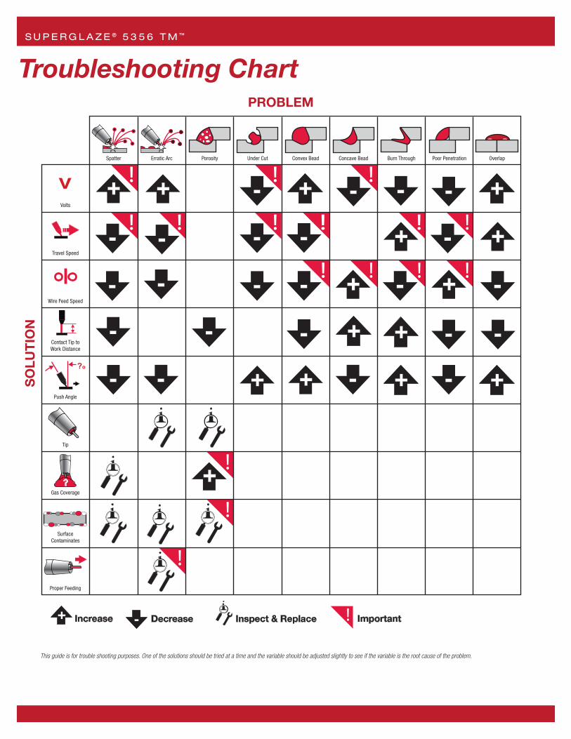
Troubleshooting ChartS U P E R G L A Z E ® 5 3 5 6 T M ™
PROBLEM
SO
LUT
ION
This guide is for trouble shooting purposes. One of the solutions should be tried at a time and the variable should be adjusted slightly to see if the variable is the root cause of the problem.
V
?o
?
+
+ +
+ ++ +
+ +
+
-Increase Decrease Inspect & Replace !
!
!
!
!
!
!
!!
!
!
!
!!
! !
! !
!
!
Important
- - - - - -
-- - - -
-- - -
Procedure Notes
Welding Safety
All listed procedures are starting points and may require some adjustment depending on the specific application.
Torch angle, electrode placement, contamination, mill scale, joint fit up and joint consistency are factors that may require special consideration depending on the specific application.
At higher travel speeds, joint fit up, wire placement and contamination all become factors that are more significant.
The results of welding at higher travel speeds is a tendency to produce more spatter, less penetration, more undercut and a less desirable bead shape. Depending on the limitations/requirements of the actual application, slower travel speeds and higher arc voltages may be required.
As the travel speed increases in fast follow applications, a tighter and arc length must be maintained so that the puddle properly follows the arc. Operators typically reduce the arc length control (Trim) to achieve this.
At faster travel speeds, the bead-shape can become very convex (or ropey) and the weld will not “wet” well. There is a point at which the arc is set so short that the arc will become unstable and stubbing will occur. This forms a limitation of just how fast the travel speed can be raised.
It is ultimately the responsibility of the end user to ensure the proper weld deposition rate, bead profile and structural integrity of a given weld application.
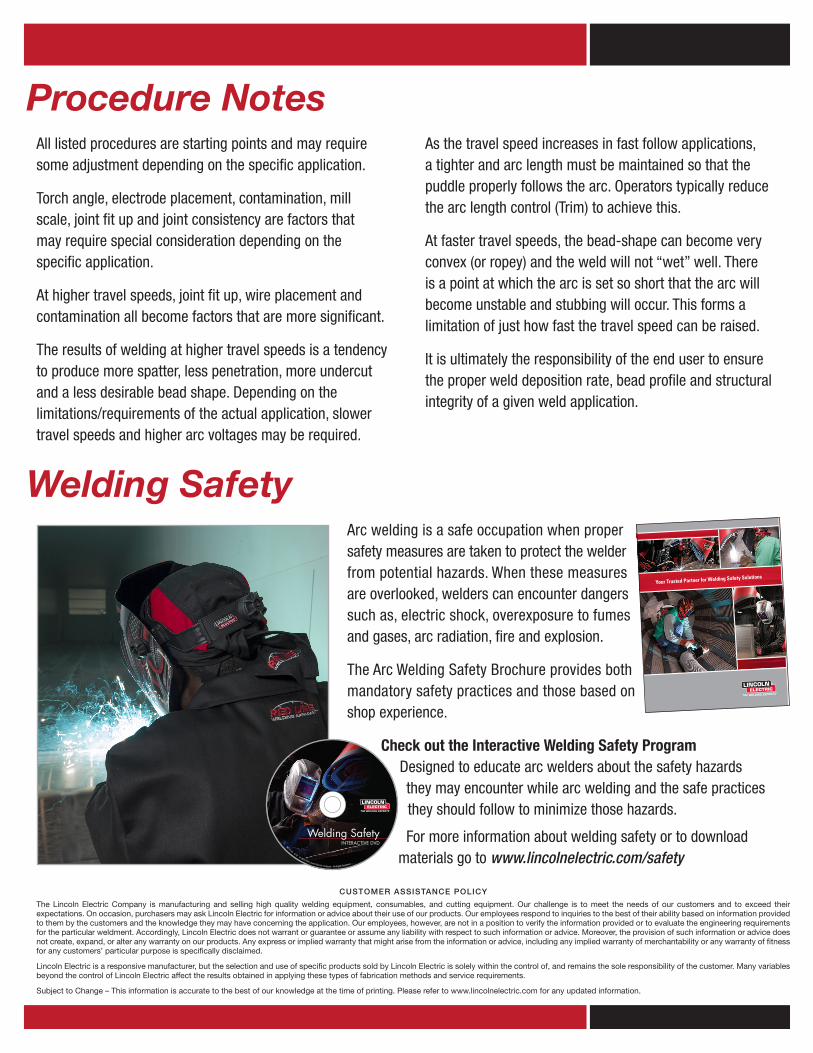
Arc welding is a safe occupation when proper safety measures are taken to protect the welder from potential hazards. When these measures are overlooked, welders can encounter dangers such as, electric shock, overexposure to fumes and gases, arc radiation, fire and explosion.
The Arc Welding Safety Brochure provides both mandatory safety practices and those based on shop experience.
Check out the Interactive Welding Safety Program Designed to educate arc welders about the safety hazards they may encounter while arc welding and the safe practices they should follow to minimize those hazards.
For more information about welding safety or to download materials go to www.lincolnelectric.com/safety
CUSTOMER ASSISTANCE POLICY
The Lincoln Electric Company is manufacturing and selling high quality welding equipment, consumables, and cutting equipment. Our challenge is to meet the needs of our customers and to exceed their expectations. On occasion, purchasers may ask Lincoln Electric for information or advice about their use of our products. Our employees respond to inquiries to the best of their ability based on information provided to them by the customers and the knowledge they may have concerning the application. Our employees, however, are not in a position to verify the information provided or to evaluate the engineering requirements for the particular weldment. Accordingly, Lincoln Electric does not warrant or guarantee or assume any liability with respect to such information or advice. Moreover, the provision of such information or advice does not create, expand, or alter any warranty on our products. Any express or implied warranty that might arise from the information or advice, including any implied warranty of merchantability or any warranty of fitness for any customers’ particular purpose is specifically disclaimed.
Lincoln Electric is a responsive manufacturer, but the selection and use of specific products sold by Lincoln Electric is solely within the control of, and remains the sole responsibility of the customer. Many variables beyond the control of Lincoln Electric affect the results obtained in applying these types of fabrication methods and service requirements.
Subject to Change – This information is accurate to the best of our knowledge at the time of printing. Please refer to www.lincolnelectric.com for any updated information.
Your Trusted Partner for Welding Safety Solutions
MC11-45 (09/11) Printed in the U.S.A. © Lincoln Global, Inc. All Rights Reserved.
The Lincoln Electric Company
Automation Division22221 Saint Clair Avenue
Cleveland, OH 44117-2522 U.S.A.
Phone: +1.216.383.2667
www.lincolnelectric.com/automated-solutions
MC10-92 8/10 © 2010 The Lincoln Electric Company All Rights Reserved.
Welding SafetyINTERACTIVE DVD

Publication C8.200 | Issue Date 11/12 ©Lincoln Global Inc. All rights reserved.
THE LINCOLN ELECTRIC COMPANY22801St.ClairAvenue•Cleveland,OH•44117-1199•U.S.A.
Phone:+1.216.481.8100•www.lincolnelectric.com