Embed Size (px)
Citation preview
Proc. Scandinavian Conference on Image Analysis, Vol. 1, pp. 235-242 (Greenland, 1999). 1
Separation of Transparent Layers by Polarization Analysis�
Yoav Y. Schechner Nahum Kiryatiy Joseph Shamir
Department of Electrical Engineering,
Technion - Israel Institute of Technology,
Haifa, Israel 32000
yDepartment of Electrical Engineering-Systems,Faculty of Engineering, Tel-Aviv University,
Ramat Aviv, Israel 69978
Abstract
Consider the phenomenon of a virtual image,
semi-re ected by a transparent medium (e.g, a
glass window) present in the scene. The semi-
re ected image is superimposed on the imageof the object that is behind the transparent
medium. A novel approach is proposed for the
recovery of the superimposed layers. An initialseparation of the layers is obtained using the raw
output of a polarizing �lter placed in front ofthe camera at two polarizer orientations. This
separation is insuÆcient at most incidence angles.
However, each pixel value in the two raw imagesis a linear combination of the corresponding pixel
values in the separate layers. The corresponding
weights depend on the re ection coeÆcients ofeach polarization component. The re ection
coeÆcients are modi�ed to account for changes
in the re ection and polarizing properties due
to internal re ections within the medium. In
principle, the separate layers are obtained by
pixel-wise inversion of the image formation
process. Experimental results, obtained using real
photos of actual objects, demonstrate the great
superiority of the suggested method over using
only raw optical data.
Keywords: Transparent layers, Re ection, Polar-ization imaging, Physics based vision.
1 Introduction
In the computer vision and image processing �elds, it
has usually been assumed that the depth and intensity,
�
at each point of the image, are single valued. However,
the situation in which several (typically two) linearly
superimposed contributions exist is often encountered in
real-world scenes. For example [5, 6, 11, 15], looking out
of a car (or room) window, we see both the outside world
(termed real object [9, 10, 11]), and a semi-re ection of
the objects inside, termed virtual objects (Fig. 1).
The treatment of such cases is important, since the
combination of several unrelated images is likely to de-
grade the ability to analyze and understand them. In
particular, the phenomenon may cause ambiguities that
will confuse vision algorithms based on feature match-
ing (such as motion and stereo). As the real and virtual
objects will usually be at di�erent distances from the
camera, this situation can certainly confuse autofocus-
ing devices. The detection of the phenomenon is of im-
portance itself, since it indicates the presence of a clear,
transparent surface in front of the camera, at a distance
closer than the imaged objects [9, 11] that contribute to
the superposition.
The term transparent layers has been used to describe
situations in which a scene is semi-re ected from a trans-
parent surface [5, 2]. The image is decomposed into
depth ordered layers, each with an associated map de-
scribing its intensity (and, if applicable, its depth or
motion). We adopt this terminology, but stress the fact
that we do not deal with imaging through an object with
variable opacity (although this is the common usage of
the term transparency). Approaches to reconstructing
each of the layers by nulling the other relied mainly on
motion [5, 2, 7, 12], stereo [14], and focus [11]. Although
algorithms were developed to cope with this problem,
fundamental ambiguities in the solutions were discov-
ered [13, 17]. Moreover, methods for the separation of
superimposed scenes that rely on defocus-blur, stereo
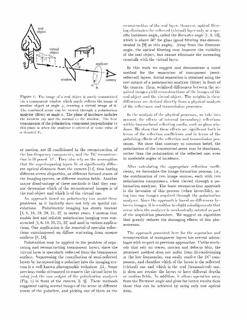
table26.ps
84 � 58 mm
virtualobject
realobject
ϕϕ
analyzer
camerawindow
αθ
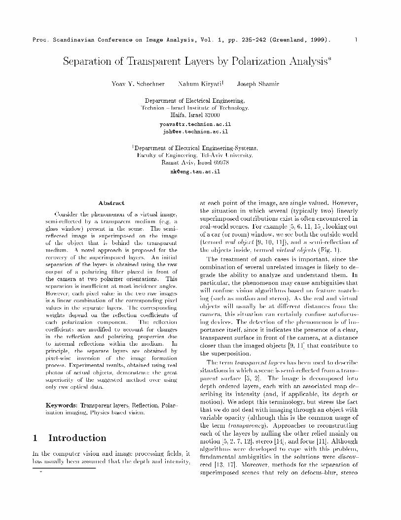
Figure 1: The image of a real object is partly transmitted
via a transparent window which partly re ects the image of
another object at angle ', creating a virtual image of it.The combined scene can be viewed through a polarization
analyzer (�lter) at angle �. The plane of incidence includes
the incident ray and the normal to the window. The besttransmission of the polarization component perpendicular to
this plane is when the analyzer is oriented at some value of
� denoted �?.
or motion, are ill conditioned in the reconstruction of
the low-frequency components, and the DC reconstruc-
tion is ill posed [11]. They also rely on the assumption
that the superimposing layers lie at signi�cantly di�er-
ent optical distances from the camera [11], thus having
di�erent stereo disparities, or di�erent focused states of
the imaging system, or di�erent motion �elds. Another
major disadvantage of these methods is that they can-
not determine which of the reconstructed images is of
the real object and which is of the virtual one.
An approach based on polarimetry can avoid these
problems, as it basically does not rely on spatial cal-
culations. Polarimetric imaging has drawn interest
[4, 8, 16, 19, 20, 21, 22] in recent years. Cameras that
enable fast and reliable polarization imaging were con-
structed [4, 6, 19, 20, 21, 22] and used in various applica-
tions. One application is the removal of specular re ec-
tions superimposed on di�use scattering from opaque
surfaces [8, 18].
Polarization may be applied to the problem of sepa-
rating and reconstructing transparent layers, since the
virtual layer is specularly re ected from the transparent
surface. Suppressing the contribution of semi-re ected
layers by incorporating a polarizer into the imaging sys-
tem is a well known photographic technique [15]. Some
previous works attempted to remove the virtual layer by
using just the raw output of the polarization analyzer
(Fig. 1) in front of the camera [6, 9]. These methods
suggested taking several images of the scene at di�erent
states of the polarizer, and picking one of them as the
reconstruction of the real layer. However, optical �lter-
ing eliminates the re ected (virtual) layer only at a spe-
ci�c incidence angle, called the Brewster angle [1, 3, 15],
which is about 56o for glass (good �ltering was demon-
strated in [9] at this angle). Away from the Brewster
angle, the optical �ltering may improve the visibility
of the real object, but cannot eliminate the increasing
crosstalk with the virtual layer.
In this work we suggest and demonstrate a novel
method for the separation of transparent (semi-
re ected) layers. Initial separation is obtained using the
raw output of a polarization analyzer (�lter) in front of
the camera. Then, weighted di�erences between the ac-
quired images yield reconstructions of the images of the
real object and the virtual object. The weights in these
di�erences are derived directly from a physical analysis
of the re ectance and transmission processes.
In the analysis of the physical processes, we take into
account the e�ects of internal (secondary) re ections
within two-surfaced re ecting media, such as glass win-
dows. We show that these e�ects are signi�cant both in
terms of the re ection coeÆcients and in terms of the
polarizing e�ects of the re ection and transmission pro-
cesses. We show that contrary to common belief, the
polarization of the transmitted scene may be dominant,
rather than the polarization of the re ected one, even
in moderate angles of incidence.
After calculating the appropriate re ection coeÆ-
cients, we formulate the image formation process, i.e.,
the combination of two image sources, each with two
polarization components, when viewed through a po-
larization analyzer. The basic reconstruction approach
is the inversion of this process (when invertible), us-
ing two raw images acquired through the polarization
analyzer. Since the approach is based on di�erences be-
tween images, it is sensitive to slight misalignments that
occur when the analyzer is mechanically rotated as part
of the acquisition procedure. We suggest an algorithm
that greatly reduces the damaging e�ects of this phe-
nomenon.
The approach presented here for the separation and
reconstruction of transparent layers has several advan-
tages with respect to previous approaches. Unlike meth-
ods that rely on stereo, motion and defocus blur, the
proposed method does not su�er from ill-conditioning
at the low frequencies, can easily resolve the DC com-
ponent, and classi�es which of the layers is the re ected
(virtual) one and which is the real (transmitted) one.
It does not require the layers to have di�erent depths
or motion �elds. In addition, it allows operation away
from the Brewster angle and gives far better results than
those that can be achieved by using only raw optical
data.
2 Internal re ections
In this section we derive the intensity transmission and
re ection coeÆcients of a double-surfaced transparent
medium, such as a glass window. The ray incident on a
surface (like the front face of window) is partly re ected
from the surface, and partly transmitted through it. All
rays are in the same plane (Fig. 2), termed the plane of
incidence [1, 3, 19]. We divide the intensity to two com-
ponents1: Ik, for which the polarization is parallel to
the plane of incidence, and I?, for which the polariza-
tion is perpendicular to it. Each component has, respec-
tively, re ection and transmission coeÆcients, Rk; R?and Tk; T?.
For a single-surface medium (e.g., water in a lake),
the re ection coeÆcients are [1, 3]
Rk =tan2('� '0)
tan2('+ '0); R? =
sin2('� '0)
sin2('+ '0); (1)
where ' is the angle of incidence (see Fig. 2). '0 is the
angle of the refracted ray, which is related by Snell's
law n sin'0 = sin', where n is the refractive index of
the re ecting medium (� 1:5 for glass). From energy
conservation considerations,
Tk = 1� Rk ; T? = 1�R? ; (2)
in case no absorption occurs in the surface. The same
coeÆcients are obtained for a ray passing from the dense
medium (e.g. glass) to the air.
Cases of re ection from double-surfaced media are,
however, by far more common than re ection by a sin-
gle surface. Typical examples are glass or polycarbonate
windows and covers of pictures. As the light ray within
the window is refracted to the air at the back surface
(Fig. 2), part of it is re ected back to the front surface,
from which refraction occurs again, and so on. As we
will show, the e�ect of internal re ections is generally
signi�cant, both in terms of the re ection coeÆcients,
and in terms of polarization. For each polarization com-
ponent the total coeÆcient of re ection is
~R = R+ T 2R
1Xl=0
(R2)l : (3)
This is true if the absorption within the window is neg-
ligible, and if the spacing between the signi�cant re-
ection orders is small relative to the variations in the
image. The latter condition is usually satis�ed since,
due to the typically small value of R, only the �rst two
orders are signi�cant and since most parts of a typical
image are smooth. However, this conditionmay not hold
near brightness edges not aligned parallel to the plane
1Natural light is usually partially linearly polarized [4], and
only rarely has a circular polarization component [16]. We thus
neglect the e�ects of circular polarization.
windo15.ps
84 � 111 mm
TI
(1- R
2
)
(1- R~ )
2
I
front
surfaceback
TI
surface
~
I
ϕ
I
RI
I R
~I R
I
’ϕ
I
I
TI2T
5R
2 R2TR2 4I
2 TIRI
~R
2TI R2R3 IT
Figure 2: The plane of incidence. When a light ray is inci-
dent on any of the window surfaces, it undergoes re ectionand refraction (transmission). The re ection (R) and trans-
mission (T ) coeÆcients for the component parallel (k) to theplane of incidence are di�erent than for the perpendicular(?) component. Internal re ections within the window give
rise to orders of re ected/transmitted rays with decreasing
intensities.
of incidence. Neglecting this e�ect (in this paper), we
obtain that the total coeÆcients of re ection are
~Rk =2
1 +RkRk ; ~R? =
2
1 + R?R? ; (4)
and the transmission coeÆcients are
~Tk =1�Rk
1 +Rk= 1� ~Rk ; ~T? =
1�R?
1 +R?= 1� ~R? : (5)
Note that the e�ect of internal re ections on the re ec-
tivity is most signi�cant when the re ection coeÆcient
is small: if R � 1 the re ectivity of a double-surfaced
medium (window) is double that of a single surface.
Consider now the in uence of the window on the po-
larization. Since light is generally partially polarized,
transmission through the analyzer (Fig. 1) is maximal
for a certain analyzing angle �, and minimal for �+90o.
The intensities at these angles are denoted Imax and
pole�34.ps
86 � 70 mm
0 10 20 30 40 50 60 70 80
0.1
0.2
0.3
0.4
0.5
0.6
0.7
0.8
0.9
1
window
ϕ
surfacereflection PE
window
transmission PEsurface
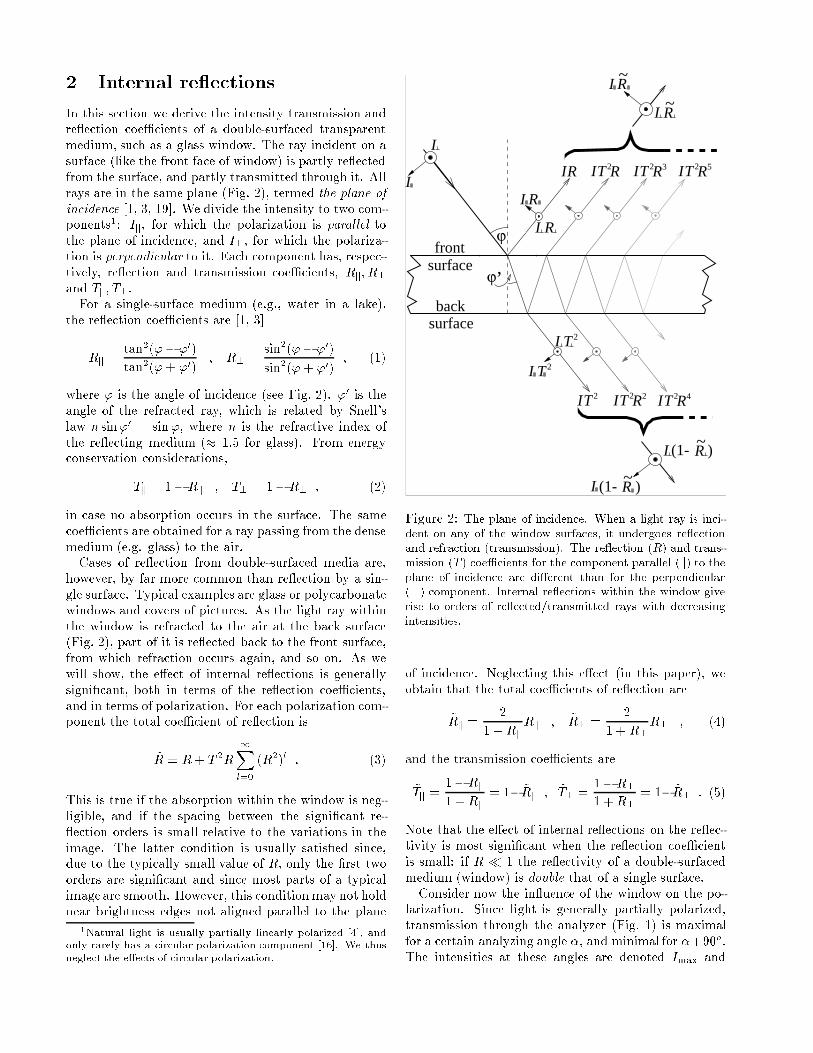
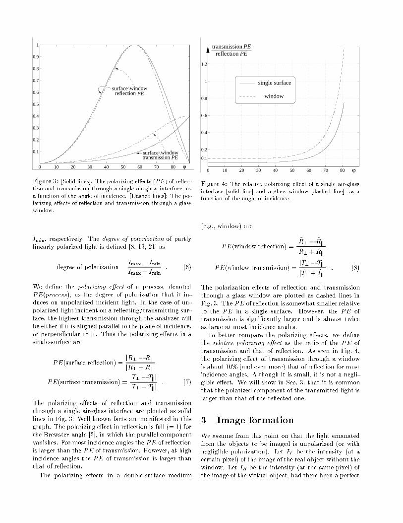
Figure 3: [Solid lines]: The polarizing e�ects (PE) of re ec-
tion and transmission through a single air-glass interface, as
a function of the angle of incidence. [Dashed lines]: The po-larizing e�ects of re ection and transmission through a glass
window.
Imin, respectively. The degree of polarization of partly
linearly polarized light is de�ned [8, 19, 21] as
degree of polarization =Imax � Imin
Imax + Imin
: (6)
We de�ne the polarizing e�ect of a process, denoted
PE(process), as the degree of polarization that it in-
duces on unpolarized incident light. In the case of un-
polarized light incident on a re ecting/transmitting sur-
face, the highest transmission through the analyzer will
be either if it is aligned parallel to the plane of incidence,
or perpendicular to it. Thus the polarizing e�ects in a
single-surface are
PE(surface re ection) =jR? �Rkj
jR? +Rkj
PE(surface transmission) =jT? � Tkj
jT? + Tkj: (7)
The polarizing e�ects of re ection and transmission
through a single air-glass interface are plotted as solid
lines in Fig. 3. Well known facts are manifested in this
graph. The polarizing e�ect in re ection is full (= 1) for
the Brewster angle [3], in which the parallel component
vanishes. For most incidence angles the PE of re ection
is larger than the PE of transmission. However, at high
incidence angles the PE of transmission is larger than
that of re ection.
The polarizing e�ects in a double-surface medium
relpe�15.ps
87 � 71 mm
0 10 20 30 40 50 60 70 80
0.1
0.2
0.4
0.6
0.8
1
1.2
1.4
ϕ
single surface
window
transmissionPEreflection
PE
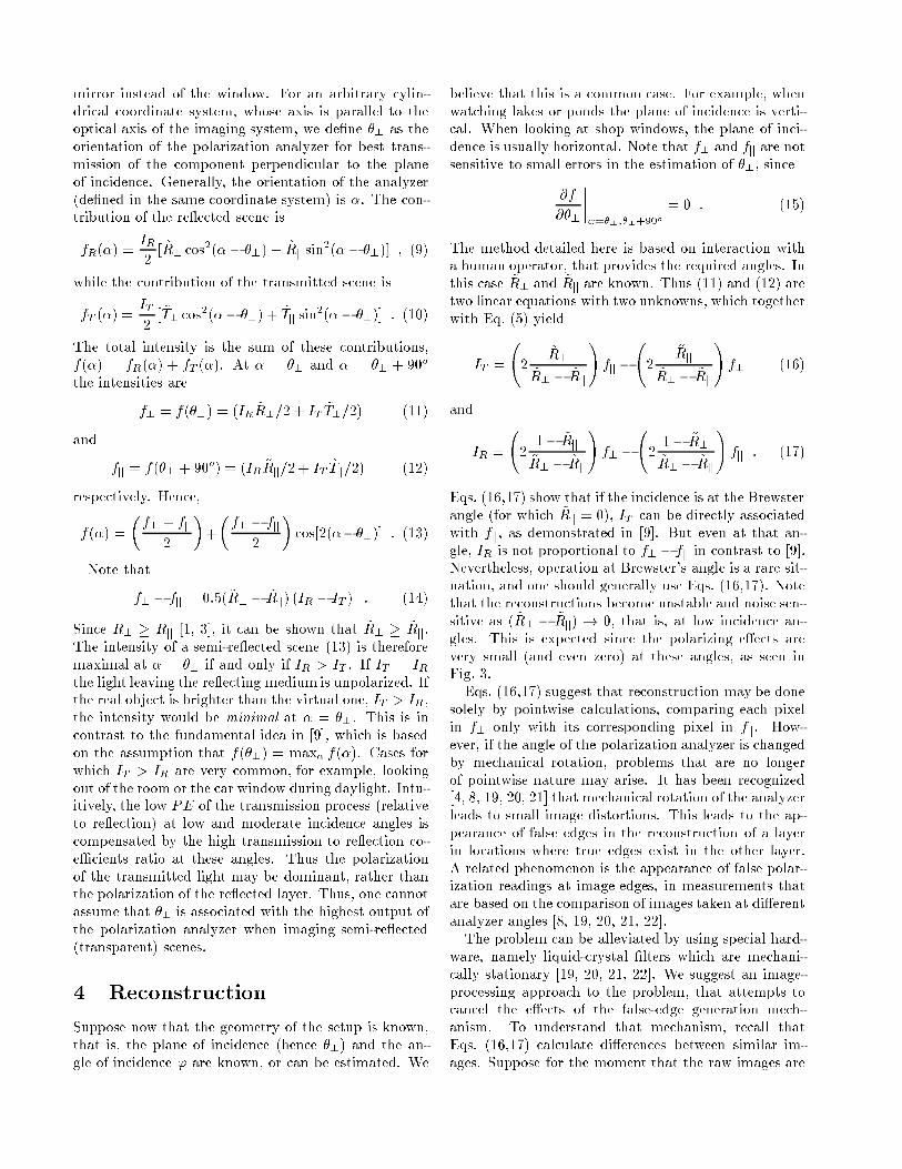
Figure 4: The relative polarizing e�ect of a single air-glass
interface [solid line] and a glass window [dashed line], as afunction of the angle of incidence.
(e.g., window) are
PE(window re ection) =j~R? � ~Rkj
j ~R? + ~Rkj
PE(window transmission) =j~T? � ~Tkj
j ~T? + ~Tkj: (8)
The polarization e�ects of re ection and transmission
through a glass window are plotted as dashed lines in
Fig. 3. The PE of re ection is somewhat smaller relative
to the PE in a single surface. However, the PE of
transmission is signi�cantly larger and is almost twice
as large at most incidence angles.
To better compare the polarizing e�ects, we de�ne
the relative polarizing e�ect as the ratio of the PE of
transmission and that of re ection. As seen in Fig. 4,
the polarizing e�ect of transmission through a window
is about 10% (and even more) that of re ection for most
incidence angles. Although it is small, it is not a negli-
gible e�ect. We will show in Sec. 3, that it is common
that the polarized component of the transmitted light is
larger than that of the re ected one.
3 Image formation
We assume from this point on that the light emanated
from the objects to be imaged is unpolarized (or with
negligible polarization). Let IT be the intensity (at a
certain pixel) of the image of the real object without the
window. Let IR be the intensity (at the same pixel) of
the image of the virtual object, had there been a perfect
mirror instead of the window. For an arbitrary cylin-
drical coordinate system, whose axis is parallel to the
optical axis of the imaging system, we de�ne �? as the
orientation of the polarization analyzer for best trans-
mission of the component perpendicular to the plane
of incidence. Generally, the orientation of the analyzer
(de�ned in the same coordinate system) is �. The con-
tribution of the re ected scene is
fR(�) =IR
2[ ~R? cos
2(� � �?) + ~Rk sin2(�� �?)] ; (9)
while the contribution of the transmitted scene is
fT (�) =IT
2[ ~T? cos
2(�� �?) + ~Tk sin2(�� �?)] : (10)
The total intensity is the sum of these contributions,
f(�) = fR(�) + fT (�). At � = �? and � = �? + 90o
the intensities are
f? = f(�?) = (IR ~R?=2 + IT ~T?=2) (11)
and
fk = f(�? + 90o) = (IR ~Rk=2 + IT ~Tk=2) (12)
respectively. Hence,
f(�) =
�f? + fk
2
�+
�f? � fk
2
�cos[2(���?)] : (13)
Note that
f? � fk = 0:5( ~R? � ~Rk) (IR � IT ) : (14)
Since R? � Rk [1, 3], it can be shown that ~R? � ~Rk.
The intensity of a semi-re ected scene (13) is therefore
maximal at � = �? if and only if IR > IT . If IT = IRthe light leaving the re ecting medium is unpolarized. If
the real object is brighter than the virtual one, IT > IR,
the intensity would be minimal at � = �?. This is in
contrast to the fundamental idea in [9], which is based
on the assumption that f(�?) = max� f(�). Cases for
which IT > IR are very common, for example, looking
out of the room or the car window during daylight. Intu-
itively, the low PE of the transmission process (relative
to re ection) at low and moderate incidence angles is
compensated by the high transmission to re ection co-
eÆcients ratio at these angles. Thus the polarization
of the transmitted light may be dominant, rather than
the polarization of the re ected layer. Thus, one cannot
assume that �? is associated with the highest output of
the polarization analyzer when imaging semi-re ected
(transparent) scenes.
4 Reconstruction
Suppose now that the geometry of the setup is known,
that is, the plane of incidence (hence �?) and the an-
gle of incidence ' are known, or can be estimated. We
believe that this is a common case. For example, when
watching lakes or ponds the plane of incidence is verti-
cal. When looking at shop windows, the plane of inci-
dence is usually horizontal. Note that f? and fk are not
sensitive to small errors in the estimation of �?, since
@f
@�?
�����=�?;�?+90o
= 0 : (15)
The method detailed here is based on interaction with
a human operator, that provides the required angles. In
this case ~R? and ~Rk are known. Thus (11) and (12) are
two linear equations with two unknowns, which together
with Eq. (5) yield
IT =
2
~R?~R? � ~Rk
!fk �
2
~Rk~R? � ~Rk
!f? (16)
and
IR =
21� ~Rk~R? � ~Rk
!f? �
21� ~R?~R? � ~Rk
!fk : (17)
Eqs. (16,17) show that if the incidence is at the Brewster
angle (for which ~Rk = 0), IT can be directly associated
with fk, as demonstrated in [9]. But even at that an-
gle, IR is not proportional to f? � fk in contrast to [9].
Nevertheless, operation at Brewster's angle is a rare sit-
uation, and one should generally use Eqs. (16,17). Note
that the reconstructions become unstable and noise sen-
sitive as ( ~R? � ~Rk) ! 0, that is, at low incidence an-
gles. This is expected since the polarizing e�ects are
very small (and even zero) at these angles, as seen in
Fig. 3.
Eqs. (16,17) suggest that reconstruction may be done
solely by pointwise calculations, comparing each pixel
in f? only with its corresponding pixel in fk. How-
ever, if the angle of the polarization analyzer is changed
by mechanical rotation, problems that are no longer
of pointwise nature may arise. It has been recognized
[4, 8, 19, 20, 21] that mechanical rotation of the analyzer
leads to small image distortions. This leads to the ap-
pearance of false edges in the reconstruction of a layer
in locations where true edges exist in the other layer.
A related phenomenon is the appearance of false polar-
ization readings at image edges, in measurements that
are based on the comparison of images taken at di�erent
analyzer angles [8, 19, 20, 21, 22].
The problem can be alleviated by using special hard-
ware, namely liquid-crystal �lters which are mechani-
cally stationary [19, 20, 21, 22]. We suggest an image-
processing approach to the problem, that attempts to
cancel the e�ects of the false-edge generation mech-
anism. To understand that mechanism, recall that
Eqs. (16,17) calculate di�erences between similar im-
ages. Suppose for the moment that the raw images are
identical. Local shifts in the raw images cause the di�er-
ence image to have high gradients where the raw images
have edges, while correctly aligned raw images do not
lead to the appearance of false edges in the di�erence
image.
Based on this observation, we attempt to align the
images, such that locally the gradients in the resulting
reconstructed (di�erence) image are minimized. It turns
out that correction by global translation is inadequate,
but small local translations lead to good results. Note
that the presence of genuine edges is typically preserved
by small local shifts.
In the method that we implemented, local shifts are
limited to single pixel movements either horizontally or
vertically. Extension of the algorithm to allow larger
movements is straightforward. The algorithm for recon-
structing IR consists of the following steps:
1. For each pixel (x; y) select the orientation o(x; y)
(either \horizontal" or \vertical") according to the
local orientation of r(f? + fk). Create regions of
coherent orientations by 2D-median (majority) �l-
tering of o(x; y) in a small neighborhood, yielding
o(x; y).
2. For Orientation = vertical, horizontal :
(a) Let f?;0 = f?. Let f?;�1 be f? shifted by �1
pixel along Orientation.
(b) Calculate IR;k (where k = �1; 0; 1) by re-
placing f? by f?;k in Eq. (17). For each of
the three images, calculate the gradient image
rIR;k.
(c) For each pixel (x; y) �nd the index k(x; y) for
which the gradient rIR;k is smallest at that
pixel.
(d) The map of k(x; y) contains many random uc-
tuations. Create regions of coherent movement
by 2D-median �ltering of k(x; y) in a small
neighborhood, yielding k(x; y).
(e) For each pixel (x; y), if o(x; y) = Orientation,
the reconstructed value is
IR(x; y) = IR;k(x;y)
:
3. Next Orientation.
Estimation of IT is similar. Note that no blurring oper-
ator is used throughout the processing.
5 Reconstruction experiment
5.1 Using optics alone
We imaged a scene composed of several objects through
an upright glass window. The window semi-re ected
another scene (virtual object). The combined scene is
shown in (Fig. 5(a)). Note that all images in this section
golmiot2.ps
87 � 86 mm
(c)(b)
(a)
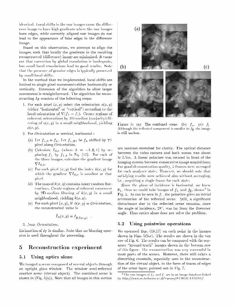
Figure 5: (a): The combined scene. (b): f?. (c): fk.Although the re ected component is smaller in fk, the image
is still unclear.
are contrast-stretched for clarity. The optical distance
between the video camera and both scenes was about
� 3:5m. A linear polarizer was rotated in front of the
imaging system between consecutive image acquisitions.
For good demonstration quality, 5 frames were averaged
for each analyzer state. However, we should note that
satisfying results were achieved also without averaging,
i.e., acquiring a single frame for each state.
Since the plane of incidence is horizontal, we knew
�?, thus we could take images of f? and fk, shown2 in
Fig. 5. As can be seen in fk, the polarizer gives an initial
attenuation of the re ected scene. Still, a signi�cant
disturbance due to the re ected scene remains, since
the angle of incidence, 28o, was far from the Brewster
angle. Thus optics alone does not solve the problem.
5.2 Using pointwise operations
We operated Eqs. (16,17) on each point in the images
shown in Figs. 5(b,c). The results are shown in the top
row of Fig. 6. The results can be compared with the sep-
arate \ground-truth" images shown in the bottom row
of this �gure. The reconstruction was very successful in
most parts of the scenes. However, there still exists a
disturbing crosstalk, especially seen in the reconstruc-
tion of the virtual object, in the form of traces of edges
of the other layer, pointed out in Fig. 7.
2The raw images of f? and fk are in an image database linked
by http://www.ee.technion.ac.il/�yoavs/PUBLICATIONS/
resexp1.ps
86 � 133 mm
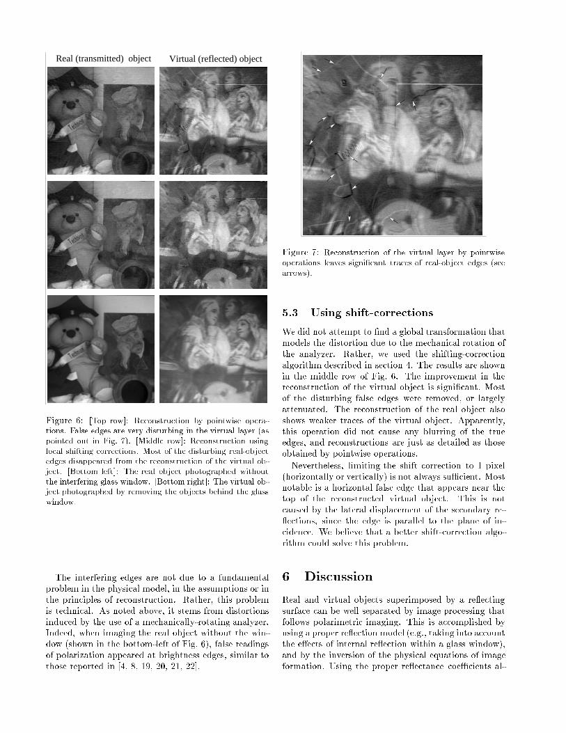
Virtual (reflected) objectReal (transmitted) object
Figure 6: [Top row]: Reconstruction by pointwise opera-tions. False edges are very disturbing in the virtual layer (as
pointed out in Fig. 7). [Middle row]: Reconstruction using
local shifting corrections. Most of the disturbing real-objectedges disappeared from the reconstruction of the virtual ob-
ject. [Bottom left]: The real object photographed without
the interfering glass window. [Bottom right]: The virtual ob-ject photographed by removing the objects behind the glass
window.
The interfering edges are not due to a fundamental
problem in the physical model, in the assumptions or in
the principles of reconstruction. Rather, this problem
is technical. As noted above, it stems from distortions
induced by the use of a mechanically-rotating analyzer.
Indeed, when imaging the real object without the win-
dow (shown in the bottom-left of Fig. 6), false readings
of polarization appeared at brightness edges, similar to
those reported in [4, 8, 19, 20, 21, 22].
ichs3.ps
70 � 70 mm
Figure 7: Reconstruction of the virtual layer by pointwise
operations leaves signi�cant traces of real-object edges (see
arrows).
5.3 Using shift-corrections
We did not attempt to �nd a global transformation that
models the distortion due to the mechanical rotation of
the analyzer. Rather, we used the shifting-correction
algorithm described in section 4. The results are shown
in the middle row of Fig. 6. The improvement in the
reconstruction of the virtual object is signi�cant. Most
of the disturbing false edges were removed, or largely
attenuated. The reconstruction of the real object also
shows weaker traces of the virtual object. Apparently,
this operation did not cause any blurring of the true
edges, and reconstructions are just as detailed as those
obtained by pointwise operations.
Nevertheless, limiting the shift correction to 1 pixel
(horizontally or vertically) is not always suÆcient. Most
notable is a horizontal false edge that appears near the
top of the reconstructed virtual object. This is not
caused by the lateral displacement of the secondary re-
ections, since the edge is parallel to the plane of in-
cidence. We believe that a better shift-correction algo-
rithm could solve this problem.
6 Discussion
Real and virtual objects superimposed by a re ecting
surface can be well separated by image processing that
follows polarimetric imaging. This is accomplished by
using a proper re ection model (e.g., taking into account
the e�ects of internal re ection within a glass window),
and by the inversion of the physical equations of image
formation. Using the proper re ectance coeÆcients al-
lows reconstruction away from the Brewster angle, that
is, where the problem cannot be solved by optics alone.
The method greatly extends the useful range of inci-
dence angles, but is inapplicable if the angle of incidence
is too small. Note that it is assumed that the light in-
cident on the window is unpolarized. The consequences
of partial polarization of the incident light are currently
being studied.
The results presented in this work can be the basis
for useful techniques in professional and amateur still-
photography, where polarizers are commonly used. The
method currently needs a human operator to feed it with
the 3D orientation of the re ecting medium. We cur-
rently study ways to extract these parameters from the
images themselves, leading to automatic operation.
Acknowledgment
This research was supported in part by the Israeli Min-
istry of Science.
References
[1] R. M. A. Azzam and N. M. Bashara, Ellipsome-
try and polarized light, pp. 269-283 (North-Holland,
Amsterdam, 1979).
[2] J. R. Bergen, P. J. Burt, R. Hingorani and S. Pe-
leg, \Transparent motion analysis" Proc. ECCV,
pp. 566-569, 1990.
[3] M. Born and E. Wolf, Principles of optics, 5th ed.,
pp. 38-45 (Pergamon, Oxford, 1975).
[4] T. W. Cronin, N. Shashar and L. Wol�, \Portable
imagingpolarimeters," Proc. ICPR, Vol-A, pp. 606-
609, 1994.
[5] T. Darrell and E. Simoncelli, \Separation of trans-
parent motion into layers using velocity-tuned
mechanisms," TR-244, Media-Lab, MIT, 1993.
[6] H. Fujikake, K. Takizawa, T. Aida, H. Kikuchi, T.
Fujii and M. Kawakita, \Electrically-controllable
liquid crystal polarizing �lter for eliminating re-
ected light," Optical Review 5, pp. 93-98, 1998.
[7] M. Irani, B. Rousso and S. Peleg, \Computing oc-
cluding and transparent motions," Int. J. Comp.
Vis. 12, pp. 5-16, 1994.
[8] S. K. Nayar, X. S. Fang and T. Boult, \Separation
of re ection components using color and polariza-
tion," Int. J. Comp. Vis. 21, pp. 163-186, 1997.
[9] N. Ohnishi, K. Kumaki, T. Yamamura and T.
Tanaka, \Separating real and virtual objects from
their overlapping images," Proc. ECCV, Vol-II,
pp. 636-646, 1996.
[10] M. Oren and S. K. Nayar, \A theory of specular
surface geometry," Proc. ICCV, pp. 740-747, 1995.
[11] Y. Y. Schechner, N. Kiryati and R. Basri, \Separa-
tion of transparent layers using focus," Proc. ICCV,
pp. 1061-1066, 1998.
[12] M. Shizawa and K. Mase, \Simultaneous multiple
optical ow estimation," Proc. ICPR pp. 274-278,
1990.
[13] M. Shizawa, \On visual ambiguities due to trans-
parency in motion and stereo," Proc. ECCV,
pp. 411-419, 1992.
[14] M. Shizawa, \Direct estimation of multiple dispar-
ities for transparent multiple surfaces in binocular
stereo," Proc. ICCV, pp. 447-454, 1993.
[15] W. A. Shurcli� and S. S. Ballard, Polarized light
(Van Nostrand, Princeton, 1964).
[16] R.Walraven, \Polarization imagery,"Opt. Eng. 20,
pp. 14-18, 1981.
[17] D. Weinshall, \Perception of multiple transparent
planes in stereo vision," Nature 341, pp. 737-739,
1989.
[18] L. B. Wol�, \Using polarization to separate re ec-
tion components," Proc. CVPR, pp. 363-369, 1989.
[19] L. B. Wol�, \Polarization camera for computer vi-
sion with a beam splitter," JOSA A 11, pp. 2935-
2945, 1994.
[20] L. B. Wol� and A. Andreou, \Polarization camera
sensors," Image and Vision Computing 13, pp. 497-
510, 1995.
[21] L. B. Wol�, \Applications of polarization camera
technology," IEEE Expert 10, pp. 30-38, 1995.
[22] L. B. Wol�, \Polarization vision: a new sensory ap-
proach to image understanding," Image and Vision
Computing 15, pp. 81-93, 1997.