Embed Size (px)
Citation preview
\
Transmutation
BR2 for
capability of the High Flux Reactor
Minor Actinides and Long Lived
Fi.ssi-on Products
by L.H. BAETSLE, Ch. DE RAEDT and A. DELBRASSINE
ABSTRACT
The high flux reactors are presently the only existing faci-
lities with the highest potential for transmutation of minor
actinides and long lived fission products. The material.
testing reactor BR2 at MOL”, BELGIUM with, in routine opera-
tion, an effective thermal neutron flux ranging, in the core,
from 2 to 4 1014 n/cm2.s; in a flux trap, up to 8 1014 n/cm2.s;
and in a reflector position, up to 4 10 14 n/cm2.s, and a large
epithermal contribution (about 0.4 1014 n/cm2.s per unit
lethargy at 5 eV in a core position).
In the sixties ‘and early seventies, important amounts of
Actinides have been irradiated for isotopic heat source
production and fabrication of higher actinides (Am, Cmr
Bk... )= The expertise and hardware for capsule irradiation
is available at the C.E.N./S.C.K. laboratories as a result of
the Pu fuel pin irradiations in extreme conditions.
The preferred form of minor actinides irradiation is the
oxide form homogeneously mixed with MgO or A1203. In case of
1-129 specific target compositions have to be selected in
order to avoid target-capsule wall interactions and the Tc-99
source form depends on the accompanying nuclides.
The quantity of nuclides which can potentially be irradiated
in the BR2 at the highest flux positions (inside fuel ele-
ments) are illustrated for the most important nuclides : Np,
Am (Cm), 1-129 and Tc-99 and the spent target compositions
are derived for a few representative cases. The neutron
shadowing and local flux depressions are taken into account
in order to obtain realistic data which can be extrapolated
to taller capsules and larger irradiation facilities.
273

The i n t e r a c t i o n b e t w e e n t h e c l a d d i n g m a t e r i a l o r t h e c a p s u l e
w a l l is o f p r i m a r y i m p o r t a n c e f o r t h e s e l e c t i o n o f l o n g term,
high fluence irradiations.
On the basis of these data, a chemical-metallurgical recyclescheme is designed in order to process the spent targets and
to reirradiate the residual nuclide inventory.
A global mass balance is given for the minor actinides in the
target capsules and in the driver fuel in order to derive the
overall radiotoxicity reduction obtainable in a P & T scheme
based on the use of high flux thermal neutron reactors.
CONTENTS
1. Introduction,,
2. The high flux materials testing reactor BR2
3. Target preparation
3 . 1 . Q u a n t i t i e s t o b e i r r a d i a t e d
3.2. Metallurgical aspects
3 .2 .1 . Neptun ium and amer ic ium targe t s
3 . 2 . 2 . I o d i n e t a r g e t s
3.2.3. T e c h n e t i u m t a r g e t
4. Irradiation, device
5. Irradiation conditions and calculated transmutation yields
6. BR2 irradiation capability
7. Discussion
8. Conclusions
274
TRANSMUTATION CAPABILITY OF THEHIGH FLUX REACTOR BR2
L.H. Baetsle, Ch. De Raedt, A. Delbrassineand A. Beeckmans de West-Meerbeeck
Belgian Nuclear Research Center
S.C.K./C.E.N., Mel, Belgium
1. INTRODUCTION
In the framework of a comprehensive Partitioning and Transmu-tation (P&T) option, the part taken by Transmutation iscrucial to achieve a reduced long term radiotoxic potential.
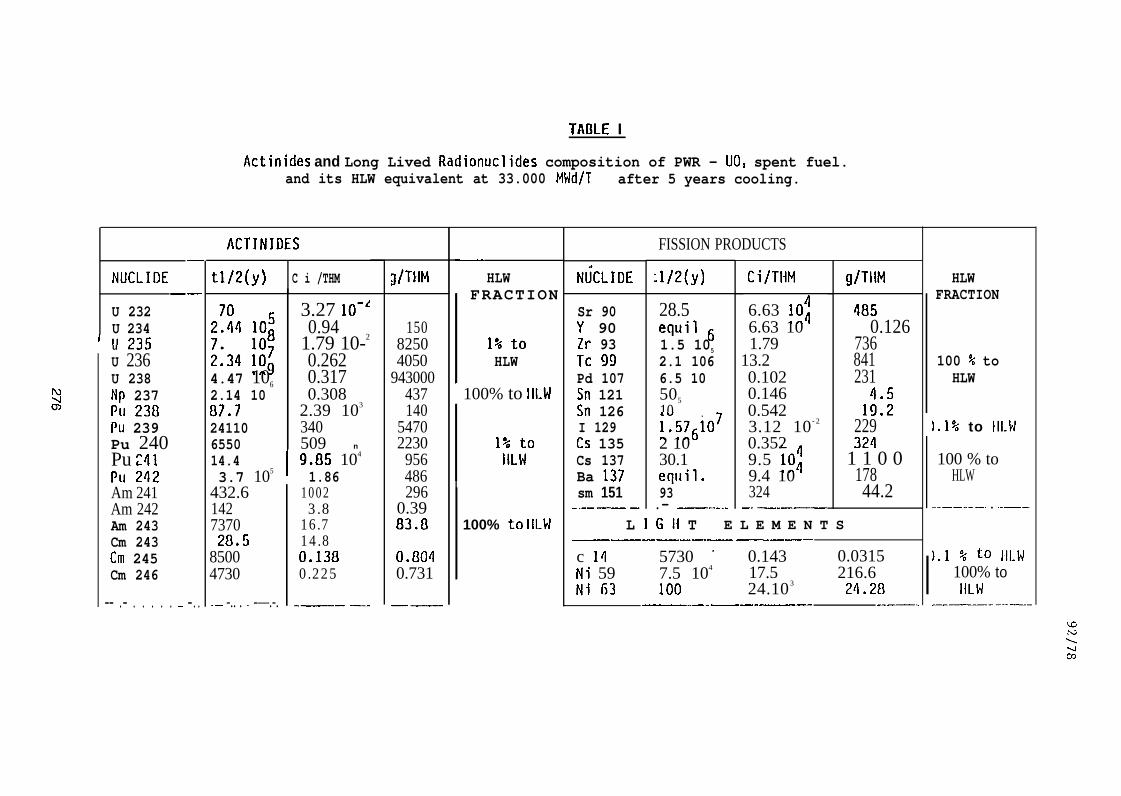
While Geological Disposal is an option which aims at protect-ing the environment from unwanted contamination by actinidesand Long-Lived .Fission Products (LLFP) during a period of upto 10000 years and in the best case up to 100000 years, itcannot guarantee e’ternal confinement. The actinides and theLLFP with half lives equal to or surpassing the mentioned pe-riods and which are critical for the validity of the disposaloption are given in Table I (taken from [1]).
The conventional backend of the fuel cycle with reprocessing,storage of HLLW and vitrification constitutes the ultimatesteps during which man can influence the source term. Inthis paper, uranium and plutonium are supposed to be recycledfor 99 % into thermal or fast fuel. The residual plutoniumand the so-called minor actinides (M.A. ) are according to thepresent practice trapped into a borosilicate matrix which issuitable for storage of fission products and actinides duringthousands of years but not for 10000 years or more.
Iodine-129, with a half-life of 16.7 M years, is presentlydischarged into the ocean as a fraction of the Medium LevelWaste effluents. Its presence in the marine biosphere willsteadily increase the global collective dose. Even if iodinewere trapped and stored, there is no geologic confinementcapable of withholding this nuclide from worldwide circula–tion.
275
TA13LE I
Actinides and Long Lived Radionuclides composition of PWR - UO, spent fuel.and its HLW equivalent at 33.000 MWd/T after 5 years cooling.
—
NUCLIDE——
U 232U 234u L.J.J
U 236U 238Np 237Pu 230Pu 239Pu 240Pu :41PU 242Am 241Am 242Am 243Cm 243Cm 245Cm 246
—— .— . . . . . .— —..
ACTINIDES
tl/2(y) C i /THM
2!:4 10:
;:34 ::;4.47 106
2.14 1007.7241106550
3.27 10-Z0.94
1.79 10-2
0.2620.3170.308
2.39 103
340509 n
14.4 9.05 104
3.7 105 1.86432.6142737020.5
85004730
.— -.. . .,. -—.-.
10023.8
16.714.80.1380.225
.—. —.-
g/THM
15082504050
943000437140
54702230
956486296
0.3983.8
0./3040.731
——
—.
HLWFRACTION
1% toHLW
b100% to Ill-w
1% toIILW
100% to Ill-w
NtiCLIDE
Sr 90Y 90Zr 93Tc 99Pd 107Sn 121Sn 126I 129Cs 135Cs 137Ba 137sm 151_.-.— —
FISSION PRODUCTS
tl/2(y)
28.5equil ~1.5 105
2.1 1066.5 10505
10L576i072 1030.1equil.93.— —--------
Ci/THM
6.63 10:6.63 101.79
13.20.1020.1460.5423.12 10 - 2
0.3529.5 10;9.4 10324
—- —-———
g/THM
4850.126
736841231
1::2229324
1 1 0 017844.2
L I Gil T E L E M E N T S—————— ——
c 14 5730 - 0.143 0.0315Ni 59 7.5 104 17.5 216.6Ni 63 100 24.10 3 24.28
——..—-—.-——- ——-
HLWFRACTION
100 % toHLW
1.1% to Ill-w
100 % toHLW
--——--—. . .-———.
).1 % to llLw100% toIILW
———-..—--
92/78
Technetium–99 , with a half-life of 2.1 E+5 years is presentas a metal or oxide in the insoluble residues and as solubleTcOA-in HLLW. According to present practice, both fractionsare combined and vitrified. Due to its long half-life andvariable valency states, this nuclide will undoubtedly mi–grate through a geological barrier which is not sufficientlyreducing. It will have a radiological impact on the ground–water in the vicinity of a geological repository.
Taking into account these well known arguments in favour ofpartial P&T f o r v e r y l o n g - l i v e d r a d i o n u c l i d e s , w e h a v e e x a -m i n e d t h e p o t e n t i a l i n v e n t o r y r e d u c t i o n o f t h e s e nuclides b yt r a n s m u t a t i o n i n a h i g h n e u t r o n f l u x f a c i l i t y . S e v e r a l so-c a l l e d “ M a t e r i a l s T e s t i n g R e a c t o r s ” ( M T R s ) a r e a v a i l a b l et h r o u g h o u t t h e w o r l d w h i c h p r o v i d e n e u t r o n f l u x e s o f E+14 t oE+15 n/cm2s. In Europe a number of MTRs are still operating :OSIRIS in France, HFR in the Netherlands and BR2 in Belgium.
2. THE HIGH FLUX MATERIALS TESTING REACTORBR2 [2 to 12]
BR2 is a heterogeneous thermal high flux MTR designed in 1957for S.C.K./C.E.N. by the Nuclear Development Corporation ofAmerica (NDA) . It has been built on the site ofS.C.K./C.E.N. at Mel, Belgium. Routine operation of thereactor started in 1963 and, to this very day, continues tocontribute to the development of many large nuclear projectswithin the European Community and for nuclear partnersthroughout the world.
The reactor is cooled and moderated by pressurized lightwater (12 bar) in a compact core of highly enriched uraniumpositioned in and reflected by a beryllium matrix. Theultimate cooling capacity, initially foreseen for 50 MW, hasbeen increased in 1971 to 125 MW.
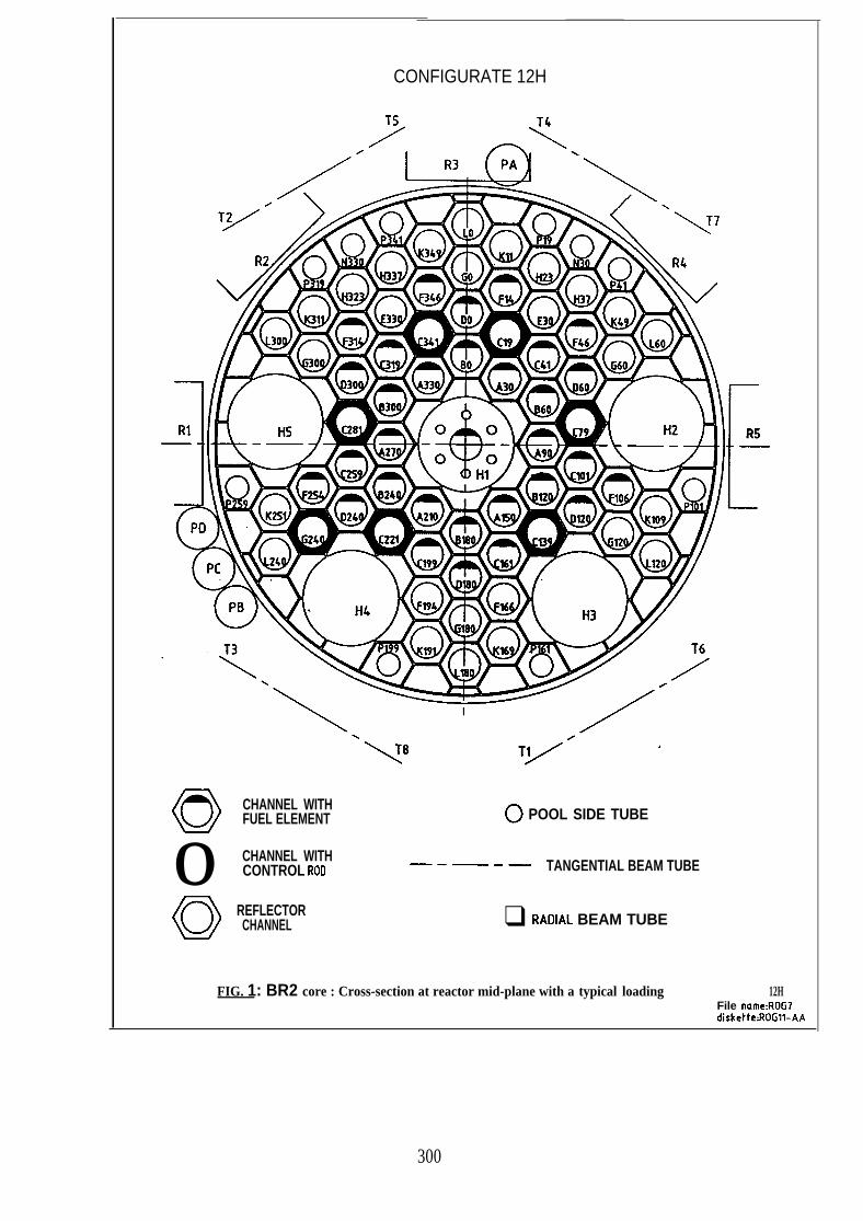
The beryllium” matrix has 79 cylindrical holes in a hexagonallattice of 96.44 mm pitch at the reactor midplane (Fig. 1);all channels have individual access through holes in the topcover of the reactor vessel. Individual guide tubes join theholes in the top cover to the holes in the matrix and thuscreate 79 individual reactor channels. There are 64 standardchannels (84 mm diam.), 10 small peripheral channels (50 mmdiam.) and 5 large channels (200 mm diam.). All the channels
277

92/78
can receive fuel elements, control rods, beryllium plugs orexperiments , which allows a great flexibility for a varietyof core arrangements. The five 200 mm channels and thirteenof the 84 mm standard channels have additional aperturesthrough the bottom cover of the reactor vessel, which allowsthrough-loop experiments.
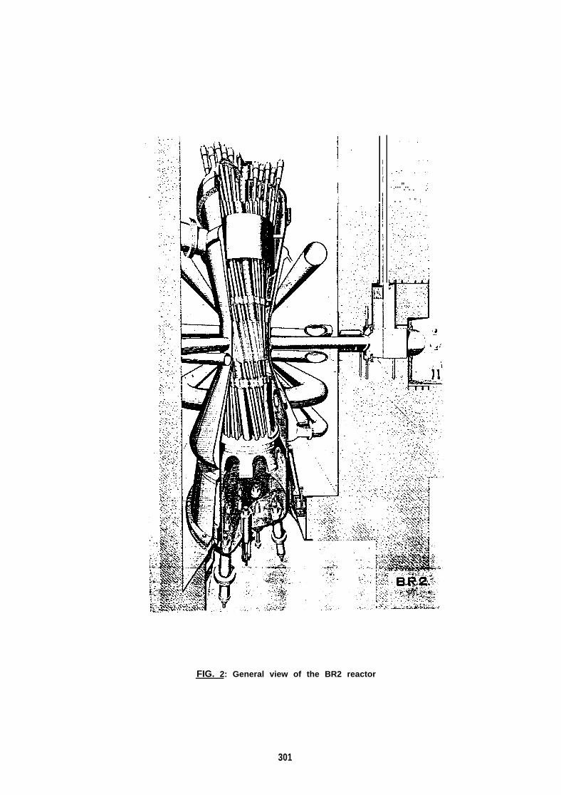
One of the most c h a r a c t e r i s t i c f e a t u r e s o f B R2 i s i t s g e o -m e t r y : t h e h e x a g o n a l B e - m a t r i x prisms fo rm a hyperboloidalb u n d l e w i t h c h a n n e l s w h i c h a r e c l o s e t o e a c h o t h e r a t t h emidplane but more apart at the lower and upper ends, i.e. atthe penetrations through the covers of the reactor pressurevessel (Fig. 2). In this array, a very high fuel density isachieved in the middle part of the vessel (reactor core)while leaving enough space at the covers for easy access tothe channel openings.
The neutron chain reaction is controlled by a number ofCd(active part)-Be(rod follower) shim safety rods and by aregulating rod, which occupy matrix lattice positions.
The standard fuel elements loaded in the 84 mm diameterchannels (Fig. 3 ) ‘are assemblies of concentric plates ortubes of about 84 mm outer diameter, each having a 762 mmfuel length. The water gap between the plates is 3 mm wide,the plate thickness is 1.27 mm. A fuel plate consists of acermet mixture of fully enriched (93 %) U AIX and burnablepoisons (BqC and Sm20~), aluminium clad. A standard fuel ele-ment of the VIG type consists of six concentric plates andallows for an experimental space having a diameter of 25.4 mmwhile a fuel element of the VG type consists of five concen-tric plates of the same composition and allows for an experi-mental space of 34 mm.
The presently used VIG fuel elements (with so-called cermet Gfuel) contain, when fresh, 400 g U-235 in the form of UAIX(1.3 gU/cm3) + 3.8 g boron (BGC) + 1.4 g samarium (Sm203).
The reactor core contains 10 to 13 kg U-235 (30 to 40 fuelelements, not all fresh). The concentration at discharge ofthe fuel elements is about 50 % of the ir.itial fissile con–tent value.
A typical BR2 reactor cycle consists of 7 days shut-down (forreloading), followed by 21 days operation. The shut-down
278
92/78
periods can be prolonged up to about 40 days for inspection,maintenance, etc.
The present nominal heat flux at the hot spot is 470 W/cmz,the maximum value allowed for nominal cooling conditions(probable onset of nucleate boiling) is 600 W/cm’. Thenominal full power depends on the core configuration used; atpresent, it ranges from 60 to 100 MW.
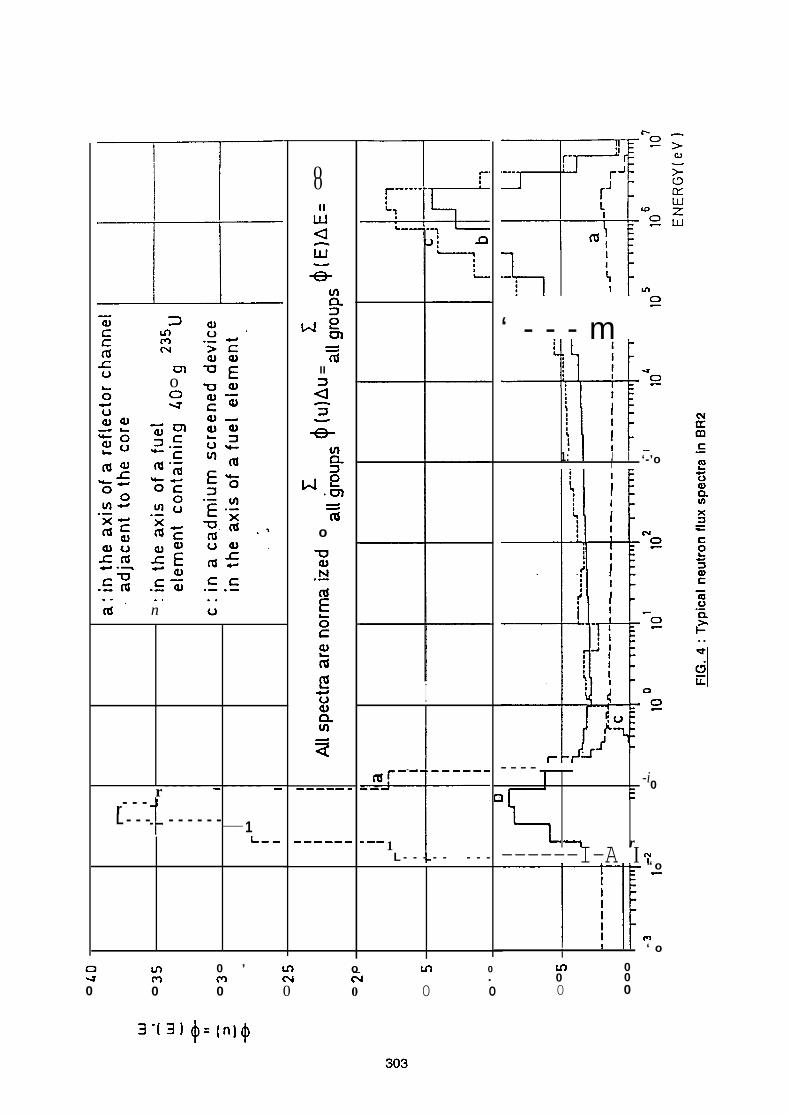
Typical neutron fluxes are (in the reactor hot spot plane) :
- thermal conventional neutron flux : VO/
0“ 5 “v n(E)dE:o
2 to 4E+14 n/cm2s in the reactor core2 to 9E+14 n/cm2s in the reflector and core flux trap (Hi)
- fast flux : ~- @( E)dE:O.l MeV
4 to 7E+14 n/c@s in the reactor core.
Typical BR2 neutron ’flux specra are shown on Fig. 4.
3. TARGET PREPARATION
3.1. QUANTITIES TO BE IRRADIATED
I n o r d e r t o a s s e s s t h e m a g n i t u d e o f t h e M.A. c o n d i t i o n i n go p e r a t i o n s i n c l u d i n g c h e m i c a l p u r i f i c a t i o n f r o m r a r e e a r t h s ,c o n v e r s i o n t o o x i d e , e n c a p s u l a t i o n a n d / o r i n c o r p o r a t i o n i nf u e l e l e m e n t s , it is n e c e s s a r y t o q u a n t i f y t h e M.A. i n v e n t o r yp r o d u c e d b y r e p r o c e s s i n g o p e r a t i o n s f r o m s p e n t L W R (33000M W d / T a f t e r 5 y e a r s c o o l i n g ) . T a b l e I I s h o w s t h e M.A. d a t ap e r T H M d i s c h a r g e d p e r G W e / y e a r a n d p e r l a r g e r e p r o c e s s i n gu n i t .
The total amount of Np + Am discharged per year from allreprocessing plants amounts at present to 3100 kg.
The quantities of long-lived fission products Tc-99 and 1-129are shown in the lower part of Table II for the same type offuel and according to the same subdivision.
279
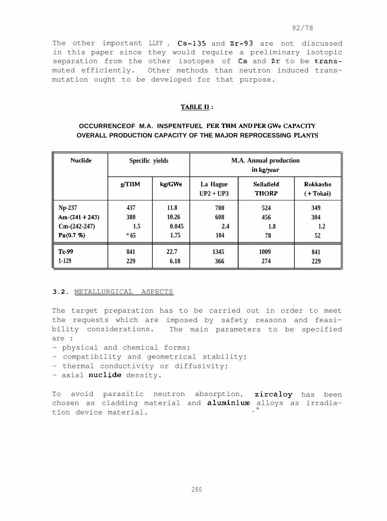
The other importantin this paper sinceseparation from themuted efficiently.
92/78
LLFP , CS-135 and Zr-93 are not discussedthey would require a preliminary isotopicother isotopes of Cs and Zr to be trans-Other methods than neutron induced trans-
mutation ought to be developed for that purpose.
TABLE1l:
OCCURRENCEOF M.A. INSPENTFUEL PERTHMAND PER GWeCAPACITYOVERALL PRODUCTION CAPACITY OF THE MAJOR REPROCESSING PLANTS
Nuclide Specific yields M.A. Annual productionin @/year
flHM kglGWe La Hague !$ellatield R(]kkashoUP2 + UP3 THORP (+Tdwi)
Np-237 437 11.8 700 524 349AIW(241+243) 380 10.26 608 456 304Cm-(242-247) 1.5 0.045 2.4 1.8 1.2PU(O.7%) “ 65 1.75 104 78 52
Tc-99 841 22.7 1345 1009 8411-129 229 6.18 366 274 229
3.2. METALLURGICAL ASPECTS
.The target preparation has to be carried out in order to meetthe requests which are imposed by safety reasons and feasi-bility considerations. The main parameters to be specifiedare :- physical and chemical forms;- compatibility and geometrical stability;- thermal conductivity or diffusivity;- axial nuclide density.
To avoid parasitic neutron absorption, zircaloy has beenchosen as cladding material and aluminium alloys as irradia-tion device material. .“
280
92/78
3 . 2 . 1 . N e p t u n i u m a n d A m e r i c i u m Tarqets
For fabrication reasons, it is suggested to prepare the M.A.targets by a sphere-pack oxide method resulting from the sol–gel route. In this case, NpOz and/or AmzO~ are mixed withA1203 or, preferably, MgO powder and vibrocompacted to obtaina bulk density of 75 % of the theoretical density.
No change in the metallurgical or geometrical stability isexpected during the first step of transmutation if the cen–terline temperature does not reach the melding point of theeutectic compound. The fissile nuclide will behave roughlyas UOZ and the geometrical stability of the target can beassured as long as the temperature does not reach the meltingpoint (T < 2000”K).
The compatibility between the target matrix and the claddingmaterial does not give rise to any problem. The fissionproducts’ mixture is not different from that resulting fromU02 but a slight change in their distribution could induce anoxidizing reaction between alkaline metal type fission pro-ducts and zircaloy. Some metallurgical in-pile tests wouldhave to be carried ’out to investigate this phenomenon and toverify any absence of chemical stress-corrosion cracking byfission products, in particular by iodine.
The thermal conductivity or diffusivity would have to bemeasured by in-pile measurements if the target is to beirradiated at a centerline temperature close to the meltingpoint.
3.2.2. Iodine taraets
Due to its high volatility even at low temperature, itsgeometrical instability (which depends on the melting pointof the compound used), and its high reactivity with the zir-caloy cladding, iodine must be loaded as iodide compound.Oxidized species have to be avoided in order to limit oxygenliberation after transmutation to Xe-130. Na, Ca and Baiodides have been considered and CaIz has been chosen as thereference compound because of its higher volume concentrationin iodine and its higher melting point (750”C). The targetis to be fabricated by loading sphere-pack CaIz into thezircaloy capsule and vibrocompacting it to 70 % T.D.
281
92/78
The compatibility between the capsule material and the Ca12–Camixture is assured as long as oxygen or oxidized compoundsare absent during transmutation. The starting procedure hasto be properly qualified because absorbed oxygen, zircaloyand metallic calcium react to form calcium-zirconate inequilibrium with metallic Zr and Ca. This reaction comes toa halt when all free oxygen has been consumed and no otherparasitic reactions are to be expected. The reaction ratecan be slowed down by keeping the cladding surface tempera-ture low enough. In-pile metallurgical tests are needed toverify the compatibility between the cladding and the CaIzloading to investigate the metallurgical stability and thepotential axial iodine migration.
The Xe-130 formation will require a vented target with aninner pressure close to the BR2 water pressure in order toavoid any stress between the outside and the inside of thecapsule as a very long irradiation time is required toachieve depletion of the target. For safety reasons, it willbe necessary to load the capsule in a closed loop device
which will limit,external contamination in.case of accidentalcladding failure.
3.2.3. Technetium Taraet
If Tc has been separated from other platinum metals, it canbe used in its metal or lower oxide form (Tc02) to be irra-diated in a zircaloy capsule. No particular problems have tobe expected during transmutation as it transforms into stableand metallurgically similar ruthenium. No second barrier isrequired nor any special safety device.
4. IRRADIATION DEVICE
In order to permit large scale transmutation of M.A. and LLFPin a MTR very stringent safety requirements have to be ful-filled. The BR2 reactor has a longstanding experience in thattype of irradiations, particularly with the production oftransuranic elements in the sixties and with a large scaleRa-226 irradiation programme in the early seventies. Quanti-ties of the order of 600 g of Ra-226 have been irradiated toproduce gramme quantities of Ac-227 and Th-228.
282

92/78
To a v o i d general contamination of the reactor in case ofaccidental failure of the capsule, special irradiation devi–ces have to be designed :
- to maintain the cladding temperature as low as possible,
to isolate the primary coolant circuit of BR2 from thehighly active targets,
- to permit an adequate siting of the capsules within a VIG
or a VG fuel element,- to become easily deactivated after prolonged residence
inside the reactor.
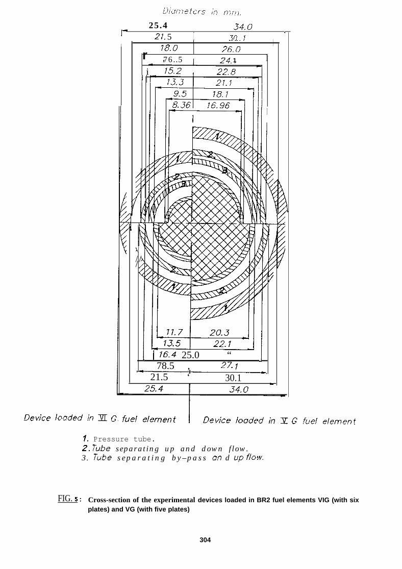
Based on the experience of previously existing experimentalirradiation devices (hydraulic rabbit, PRF) a closed pressu-rized water circuit was chosen as basic design. This loop iscooled by the primary cooling water of the BR2 reactor andthe water temperature would be roughly 10”C above the primarycooling circuit temperature. The internal pressure of theloop equals that of the reactor cooling circuit in order toallow the use of light alloys and small wall thicknesses.The device has to be protected against local overheating incase of accidental ‘blockage of the cooling duct. Therefore,a bypass-cooling with a heat dissipation capacity exceedingthe critical heat flux has to be foreseen. Different experi-mental arrangements are shown on Fig. 5, which displays fourdifferent target-fuel assembly configurations within a VIG
and a VG fuel element.
To perform scouting neutronic computations it was decided toconsider two target diameters for Am, Np and I : 0.836 and1.696 cm depending on the loading within a VIG or a VG fuelelement. For Tc, the target diameters considered were 1.170and 2.030 cm.
The bottom parts of the Tables IV and V show the results ofthe thermal computations of the linear fission power and theCentre-line temperature of targets loaded with Am and Np.The Am targets with a large diameter must be limited in luncontent in order to avoid target centre melting.
Furthermore, it can be stated that below 400 W/cm, no changein geometrical stability is expected for Am and Np targetswhile below 150 W/cm no accidental events can occur.
283
92/78
For CaIz targets, the main point is to avoid any volatiliza–tion of iodine or iodine compound. Therefore the centre–linetemperature has to be kept below 700”C and consequently themaximum linear power must be lower than 40 W/cm. Tests onthe geometrical stability of Ca12 are of utmost importancebefore starting an isotopic transmutation programme.
5. IRRADIATION CONDITIONSAND CALCULATED TRANSMUTATION YIELDS
T r a n s m u t a t i o n r e a c t i o n s o f Np-237 a n d A m - 2 4 1 b y t h e r m a ln e u t r o n a b s o r p t i o n y i e l d d u r i n g e x t e n d e d i r r a d i a t i o n program-med o f s e v e r a l y e a r s e s s e n t i a l l y Pu-238 w i t h a h a l f - l i f e o f8 8 y e a r s a n d f i s s i o n p r o d u c t s . A m - 2 4 3 i s s l o w l y t r a n s f o r m e di n t o C m - 2 4 4 w i t h a h a l f - l i f e o f 1 8 y e a r s .N e u t r o n c a p t u r e o f Tc-99 y i e l d s inactive R u - 1 O O w h i l e 1 - 1 2 9t r a n s f o r m s into g a s e o u s Xe-130. ( S e e f u r t h e r , T a b l e V I I I ) .
The neutron calculations were carried out, in one-dimensionalcylindrical geometry, with following codes and neutron libra-ries :
- for the Am and Np targets :with the ANISN neutron transport code [13] (part of theMARS-AMPEX code system [14]), with a coupled fast-thermal27 group library obtained by group-collapsing (from 218 to27 groups) from [15].In the 218 and 27 group libraries, self-shielding correc-tions in the resonance region are allowed for (Nordheimformalism, with the NITAWL code) for the nuclides Am-241and Np-237 (not for Am-243).
- for the I and Tc targets :with a S.C.K./C.E.N. version of the DTF-IV neutron trans-port code [16] (part of the MULCOS code system [17]), withthe coupled fast-thermal 40 group library [18]. The 40group cross-section sets (without resonance self-shieldingcorrection ) for 1-129 and Tc-99 were calculated atS.C.K./C.E.N. starting from the resonance parameters givenin [19].
284
92/78
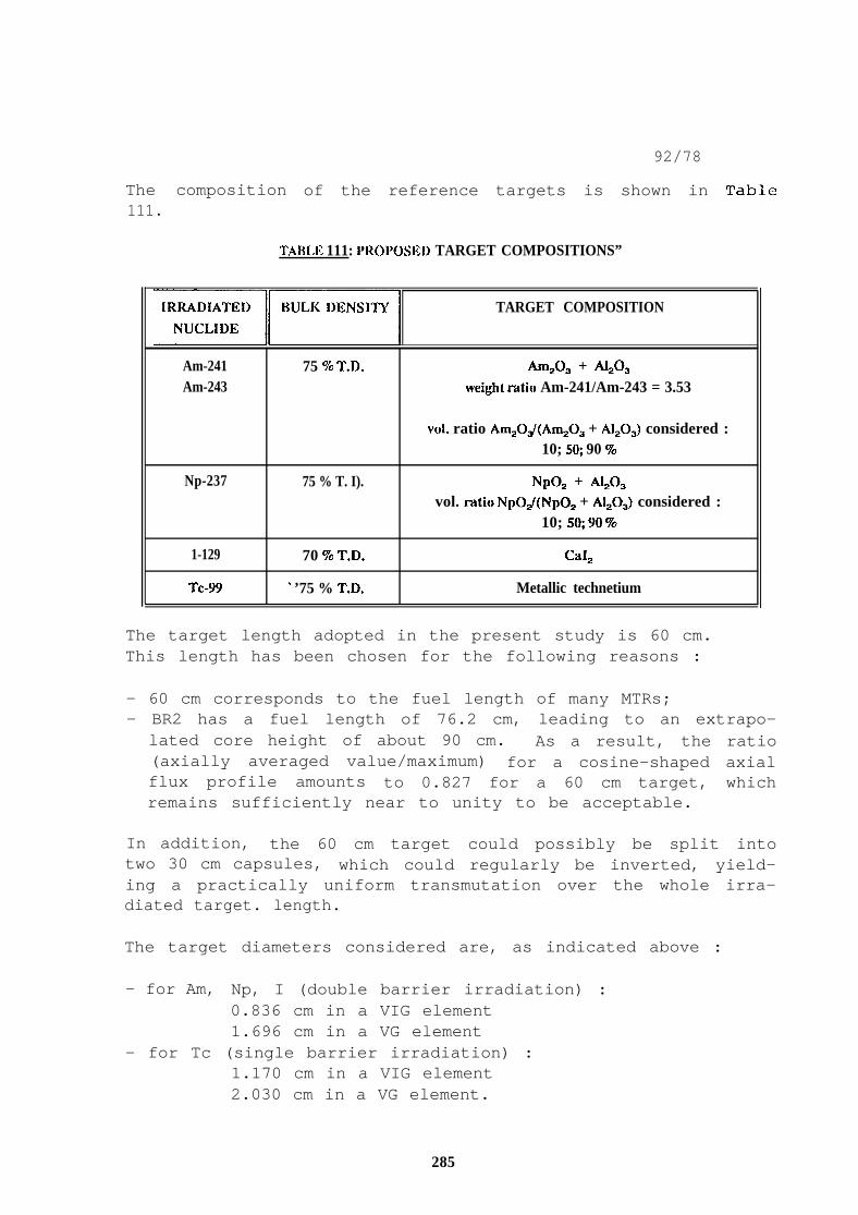
The composition of the reference targets is shown in Table111.
TABLE 111: I’ROI’OSEl) TARGET COMPOSITIONS”
EElr TARGET COMPOSITION
Am-241 75 % T.D. AM*03 + ~03Am-243 weight ratio Am-241/Am-243 = 3.53
vol. ratio Am20J(Am203 + A120J considered :10; S@ 90 %
Np-237 75 % T. I). Np02 + Alzoavol. r~tio NpOJ(Np02 + AIJ)J considered :
10; s% 90 To
1-129 70 Yo T.D. Ca12
Tc-W ‘ ’75 % T.D. Metallic technetium
The target length adopted in the present study is 60 cm.This length has been chosen for the following reasons :
- 60 cm corresponds to the fuel length of many MTRs;- BR2 has a fuel length of 76.2 cm, leading to an extrapo-
lated core height of about 90 cm. As a result, the ratio(axially averaged value/maximum) for a cosine-shaped axialflux profile amounts to 0.827 for a 60 cm target, whichremains sufficiently near to unity to be acceptable.
In addition, the 60 cm target could possibly be split intotwo 30 cm capsules, which could regularly be inverted, yield-ing a practically uniform transmutation over the whole irra-diated target. length.
The target diameters considered are, as indicated above :
- for Am, Np, I (double barrier irradiation) :0.836 cm in a VIG element1.696 cm in a VG element
- for Tc (single barrier irradiation) :1.170 cm in a VIG element2.030 cm in a VG element.
285

92/78
As already explained, the cladding material adopted for alltargets is zircaloy-4.
The irradiation conditions adopted for the neutron irradia–tion in BR2 are as follows :
- the clad target and the surrounding aluminium tubes are
introduced into a VIG or VG type fuel element with a burn–up of 40 %;
- the surroundings of the channel containing this VIG or VGfuel element are arranged in a hexagonal configuration(“crown”) of channels of which 4 contain fuel elements ofthe VIG type with 20 % burn-up and 2 contain a berylliumreflector plug;
- the power of this hexagonal “crown” amounts to 8 MW;- the irradiation duration is assumed to be 200 EFPD (= 1
calendar year).
This corresponds practically to an irradiation in a B R2channel such as. C-41, C-101, B-240, C-259, B-300, C-319 etc.on Fig. 1.
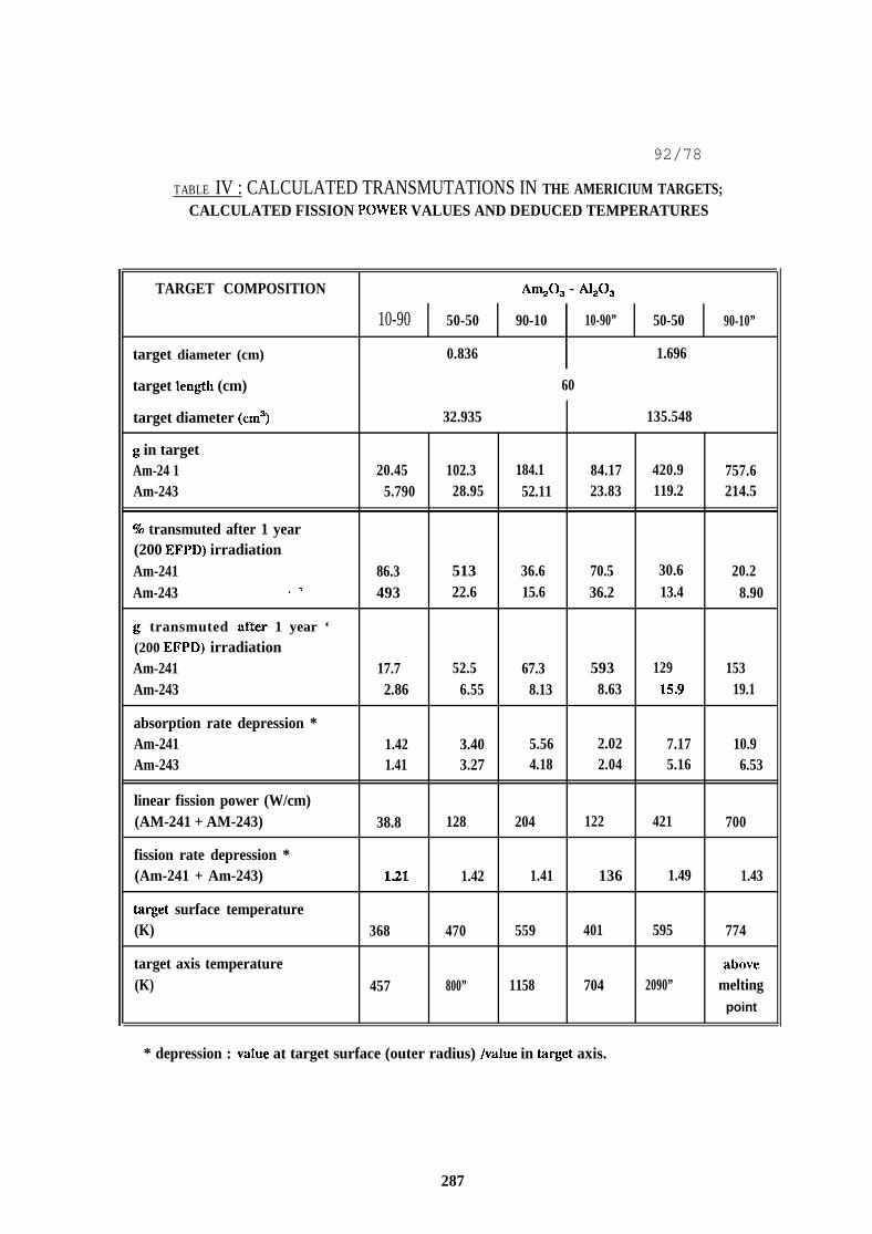
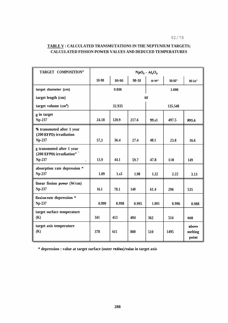
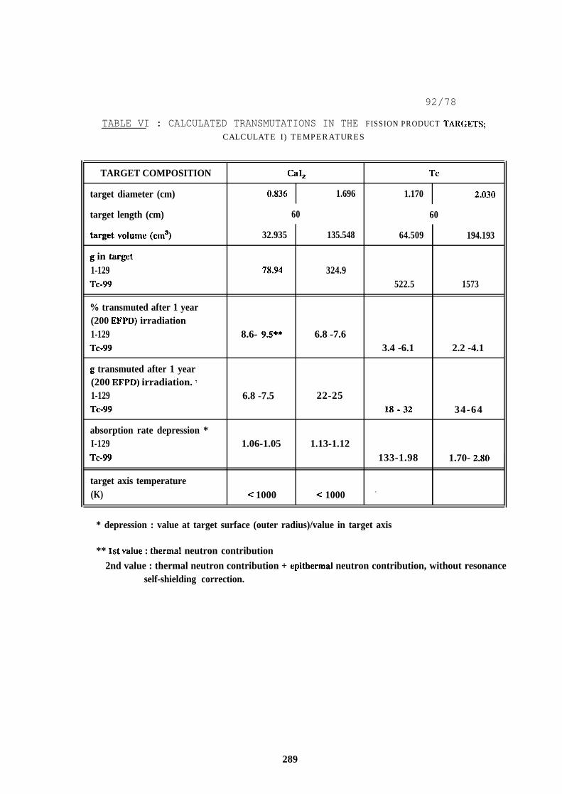
The target volumes, the quantities of actinides or fissionproducts contained in one target before irradiation, thepercentage transmutation obtained after 200 EFPD and thecorresponding quantities of actinides or fission productstransmuted per target are indicated in Tables IV, V and VI
for americium, neptunium and fission product targets, respec-tively.
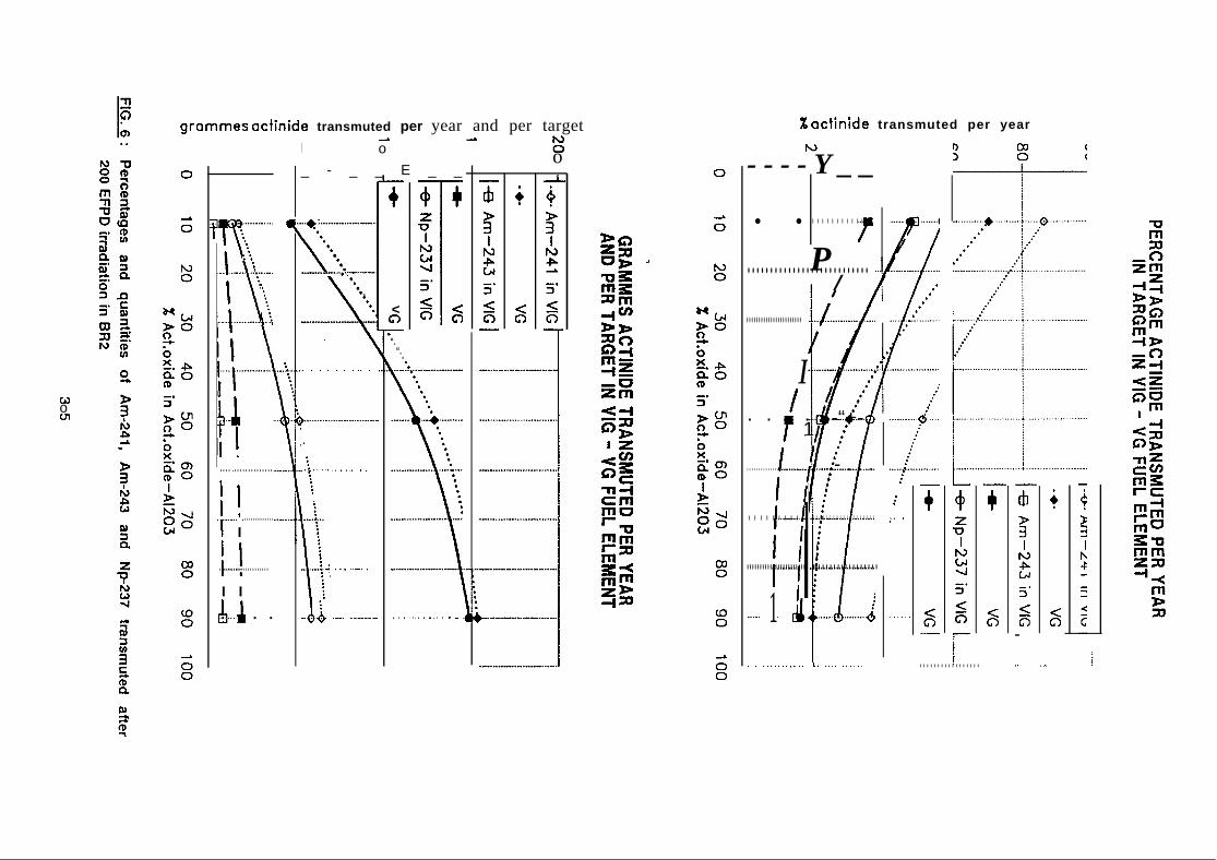
The percentages and quantities of Am-241, Am-243 and Np-237transmuted after 200 EFPD are indicated’ in Fig. 6, as afunction of the vol.% AnzO~ (or NpOz) in the AmzO~ + AlzOJ (orNpOz + A120J) matrix.
286
92/78
TABLE IV : CALCULATED TRANSMUTATIONS IN THE AMERICIUM TARGETS;CALCULATED FISSION POWER VALUES AND DEDUCED TEMPERATURES
TARGET COMPOSITION Am203 - A1203
10-90 50-50 90-10 10-90” 50-50 90-10”
target diameter (cm) 0.836 1.696
target len@l (cm) 60
target diameter (cm3) 32.935 135.548
g in targetAm-24 1 20.45 102.3 184.1 84.17 420.9 757.6Am-243 5.790 28.95 52.11 23.83 119.2 214.5
70 transmuted after 1 year(200 EFPI)) irradiationAm-241 86.3 513 36.6 70.5 30.6 20.2Am-243 ,-, 493 22.6 15.6 36.2 13.4 8.90
g transmuted after 1 year ‘(200 EFPD) irradiationAm-241 17.7 52.5 67.3 593 129 153Am-243 2.86 6.55 8.13 8.63 15.9 19.1
absorption rate depression *Am-241 1.42 3.40 5.56 2.02 7.17 10.9Am-243 1.41 3.27 4.18 2.04 5.16 6.53
linear fission power (W/cm)(AM-241 + AM-243) 38.8 128 204 122 421 700
fission rate depression *(Am-241 + Am-243) 121 1.42 1.41 136 1.49 1.43
target surface temperature(K) 368 470 559 401 595 774
target axis temperature above(K) 457 800” 1158 704 2090” melting
point
* depression : value at target surface (outer radius) /vtilue in target axis.
287
92/78
TABLE V : CALCULATED TRANSMUTATIONS IN THE NEPTUNIUM TARGETS;CALCULATED FISSION POWER VALUES AND DEDUCED TEMPERATURES
TARGET COMPOSITION” NP02 - A12Q
10-90 50-50 90-10 10-90” 50-50” 90-1o”
target diameter (cm) 0.836 1.696
target length (cm) 60
target volume (cm3) 32.935 135.548
g in targetNp-237 24.18 120.9 217.6 99.s1 497.5 895.6
70 transmuted after 1 year(200 EFPD) irradiationNp-237 57,3 36.4 27.4 48.1 23.8 16.6
g transmuted after 1 year(200 EFPD) irradiation” ‘Np-237 . 13.9 44.1 59.7 47.8 118 149
absorption rate depression *Np-237 1.09 1.s3 1.98 1.22 2.22 3.13
linear fission pOwer (W/cm)Np-237 16.1 78.1 140 61.4 296 535
fission rdte depression *Np-237 0.999 0.998 0.995 1.001 0.996 0.988
target surface temperature(K) 341 413 484 362 514 668
target axis temperature abuve(K) 378 611 880 510 1495 melting
pOint
* depression : value at target surface (outer radhs)/value in target axis
288
92/78
TABLE VI : CALCULATED TRANSMUTATIONS IN THE FISSION PRODUCT TAI{(;ETS;
CALCULATE I) TEMPERATURES
TARGET COMPOSITION CiII, Tc
target diameter (cm) 0.836 1.696 1.170 2.030
target length (cm) 60 60
target volume (cm3) 32.935 135.548 64.509 194.193
g in target1-129 78.94 324.9Tc-99 522.5 1573
% transmuted after 1 year(200 EFPD) irradiation1-129 8.6- 9.5** 6.8 -7.6Tc-99 3.4 -6.1 2.2 -4.1
g transmuted after 1 year(200 EFPD) irradiation. ‘1-129 6.8 -7.5 22-25Tc-99 18-32 34-64
absorption rate depression *I-129 1.06-1.05 1.13-1.12Tc-W 133-1.98 1.70- 2.N)
target axis temperature(K) < 1000 < 1000 -
* depression : value at target surface (outer radius)/value in target axis
** 1st value : thermal neutron contribution
2nd value : thermal neutron contribution + epithermal neutron contribution, without resonanceself-shielding correction.
289
92/78
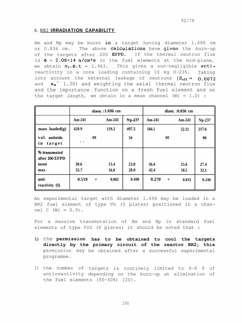
6. BR2 IRRADIATION CAPABILITY
Am and Np may be burnt in a target having diameter 1.696 cmor 0.836 cm. The above ,calculati.ons have given the burn-upof the targets after 200 EFPD. If the thermal neutron fluxis @ = 2.0E+14 n/cm2s in the fuel elements at the mid-plane,we obtain af.o.t = 1.963. This gives a non-negligible anti-reactivity in a core loading containing 10 kg U-235. Takinginto account the external leakage of neutronsand K. =
(% = 0.00721.30) and weighting the axial thermal neutron flux
and the importance function on a fresh fuel element and onthe target length, we obtain in a mean channel (Wi = 1.0) :
dlam. :1.696 cm diam. :0.836 cm
Am-241 Am-243 Np-237 Am-241 Am-243 Np-237
mass loaded(g) 420.9 119.2 497.5 184.1 52.11 217.6
vol . %actinide 50 50 90 90. .
i n t a r g e t
%transrnutedafter 20(l EFPDmean 30.6 13.4 23.8 36.6 15.6 27.4max. 35.7 16.0 28.0 42.4 18.5 32.1
anti- 0.519 + 0.065 0.490 0.270 + 0.033 0.246reactivity ($)
An experimental target with diameter 1.696 may be loaded in aBR2 fuel element of type VG (5 plates) positioned in a chan-nel C (Wi = 0.9).
For a massive transmutation of Am and Np in standard fuelelements of type VIG (6 plates) it should be noted that :
1)
2)
the permission has to be obtained to cool the targetsdirectly by the primary circuit of the reactor BR2; thispermission mayprogramme.
the number ofantireactivity
be obtained after a successful experimental
targets is routinely limited to 6-8 $ ofdepending on the burn-up at elimination of
the fuel elements (50-40%) [20].
290
92/78
This allows the irradiation of 12 targets of large diameter1.696 cm in the channels C (Wi = 0.9) and D (Wi= 0.7),(whilst the channels A and B in the central ring have astatistical weight of about Wi = 1.5) or of 24 targets ofsmall diameter 0.836 cm in the channels A, B, C, D. In bothcases the consumption rate of Am and Np will be equivalent.
Advanced driver fuel elements of the type VIH containing
520 g U-235 instead of 400 g U-235 could be fabricated in thefuture to load 24 targets of large diameter with 50 vol.%actinide content in the channels A, B, C, D. In that case3.5 kg Am or 2.8 kg Np could be burnt yearly in BR2.
7. DISCUSSION
The thermal data of tables IV and V indicate that the highestacceptable concentration of ~ resp. Np in a 1.696 cm diame-ter capsule is a 50/50 ratio of actinide to aluminium. Insmall diameter targets (O. 836 cm) no critical temperaturelevel is attained but the quantities which can be irradiatedper target are 4 times smaller.
As w a s t o b e e x p e c t e d , t h e p e r c e n t a g e o f a c t i n i d e t r a n s m u t e dp e r t a r g e t i n 2 0 0 E F P D d e c r e a s e s a s actinide/aluminium ratioa n d t a r g e t s i z e i n c r e a s e . T h e p e r c e n t a g e s o f A m - 2 4 1 a n d o fNp-237 t r a n s m u t e d p e r 2 0 0 E F P D a r e r o u g h l y t h e s a m e a n d r a n g efrom 27 to 86 % in the small targets and from 24 to 70 % int h e l a r g e t a r g e t s . T h e N p - 2 3 7 a n d A m - 2 4 1 c o n t e n t o f a t a r g e tc a n b e d e p l e t e d in a f e w y e a r s o f i r r a d i a t i o n .T h e A m - 2 4 3 d e p l e t i o n is s m a l l e r b e c a u s e o f t h e l o w e r n e u t r o na b s o r p t i o n c r o s s - s e c t i o n s .
The transmutation yields of 1-129 and Tc-99 are shown inTable VI and appear to be very small due to the very lowneutron capture cross-sections.
The use of a high flux reactor for target transmutationstudies has to be viewed from the overall mass balance in thereactor fuel. Table VII [21] shows the quantities of fissilematerial depleted and actinides + LLFP formed per reactorfuel element and in the whole reactor core operating during200 EFPD.
291
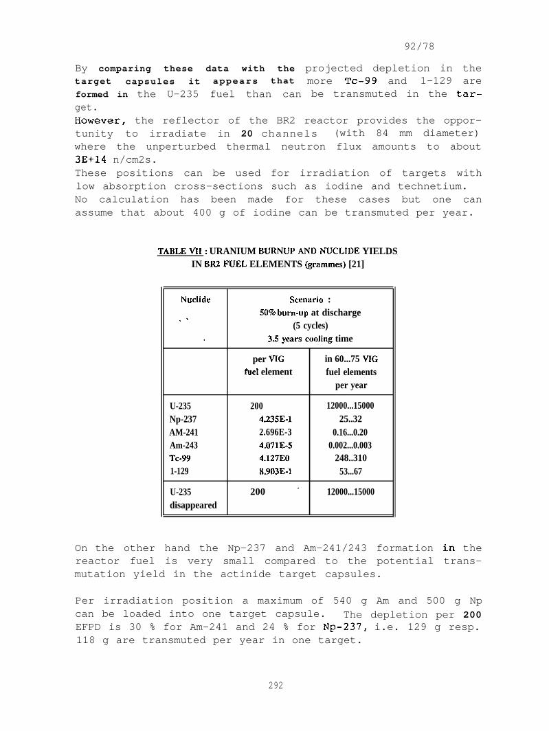
By comparing these data with the
target capsules it appears that
formed in the U-235 fuel than canget.
92/78
projected depletion in themore Tc-99 and 1–129 arebe transmuted in the tar–
EIowever, the reflector of the BR2 reactor provides the oppor-tunity to irradiate in 20 channels (with 84 mm diameter)where the unperturbed thermal neutron flux amounts to about3E+14 n/cm2s.These positions can be used for irradiation of targets withlow absorption cross-sections such as iodine and technetium.No calculation has been made for these cases but one canassume that about 400 g of iodine can be transmuted per year.
TABLEVII: URANIUM BURNUPANDNUCLIDE YIELDSIN BR2FUEL ELEMENTS (grammes) [21]
Nuclide Scenario :5070b urn-up at discharge.-,
(5 cycles). 3.5yeursc001ing time
per VIG in 60...75 VIGfuel element fuel elements
per year
U-235 200 12000...15000Np-237 4.235E-1 25..32AM-241 2.696E-3 0.16...0.20Am-243 4.071E-5 0.002...0.003Tc-99 4.127E0 248..3101-129 IL903E-1 53...67
U-235 200 ‘ 12000...15000disappeared
On the other hand the Np-237 and Am-241/243 formation in thereactor fuel is very small compared to the potential trans-mutation yield in the actinide target capsules.
Per irradiation position a maximum of 540 g Am and 500 g Npcan be loaded into one target capsule. The depletion per 200EFPD is 30 % for Am-241 and 24 % for Np-237, i.e. 129 g resp.118 g are transmuted per year in one target.
292
92/78
The number of target capsules which can be loaded into thereactor is limited by the antireactivity of the targets andthe number of available positions (24). In the case of BR2,a total antireactivity of 6 to 8 $ can be accepted in thereactor at the present time, while each capsule produces anantireactivity of about 0.5 $.
Under these circumstances, a maximum of about 12 targets canbe loaded with a total mass of about 6 kg Am or Np or amixture of both. The transmutation capacity of the reactorif it were dedicated to such R&D programmed is about 1.5 kgAm or Np per year .
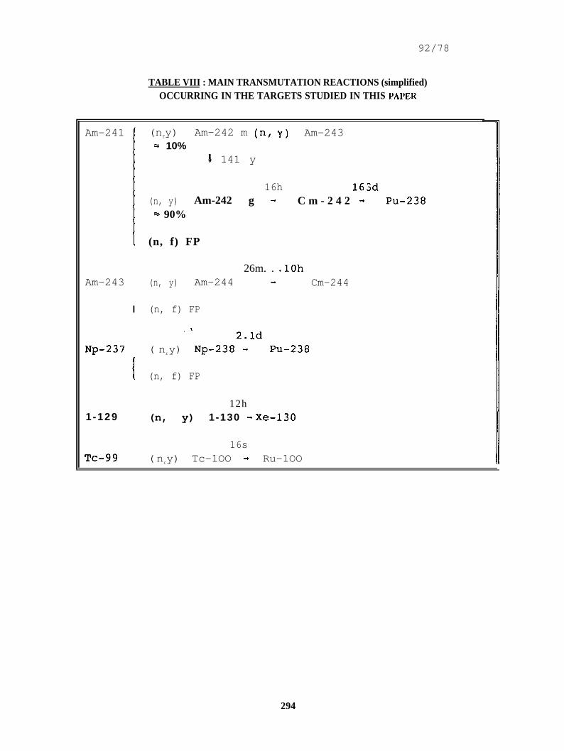
A s i n d i c a t e d in T a b l e V I I I , A m - 2 4 1 is t r a n s m u t e d i n t o A m - 2 4 2( a b o u t 1 0 % i n t o t h e 1 4 1 y i s o m e r , a b o u t 9 0 % i n t o t h e 1 6 hi s o m e r ) ; h e n c e a b o u t 9 0 % i s f i n a l l y t r a n s m u t e d i n t o C m - 2 4 2 ,w h i c h , w i t h a h a l f - l i f e o f 1 6 3 d a y s , d e c a y s into P u - 2 3 8 .A m - 2 4 3 i s t r a n s m u t e d i n t o A m - 2 4 4 w h i c h d e c a y s r a p i d l y i n t oC m - 2 4 4 ( 1 8 y ) .Np-237 is t r a n s m u t e d into N p - 2 3 8 w h i c h d e c a y s ( w i t h a half-life o f 2 . 1 d a y s ) i n t o PU-238.H e n c e t h e b u l k o f t h e t w o a c t i n i d e t a r g e t t y p e s c o n s i d e r e d i nt h i s p a p e r i s u l t i m a t e l y t r a n s m u t e d i n t o Pu-238.
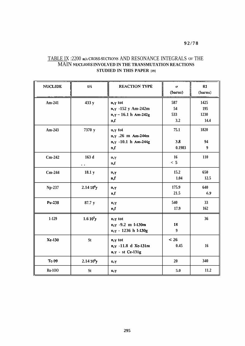
T h e 2 2 0 0 m / s c r o s s - s e c t i o n s (a) a n d t h e r e s o n a n c e i n t e g r a l s( R I ) o f t h e main n u c l i d e s i n v o l v e d i n t h e s e t r a n s m u t a t i o n sare indicated in Table IX [19].
The “half-life” of both Am-241 and Np-237 equalseven less, depending on the type of target, whenin the BR2 reactor.
2 y e a r s o ri r r a d i a t e d
293
92/78
TABLE VIII : MAIN TRANSMUTATION REACTIONS (simplified)OCCURRING IN THE TARGETS STUDIED IN THIS PAPER
Am-241 (nfy) Am-242 m (n, y) Am-243= 10%
4 141 y
16h 163d(n, y) Am-242 g + C m - 2 4 2 + Pu-238
= 90%
(n, f) FP
26m. . .lOhAm-243 (n, y) Am-244 - Cm-244
I (n, f) FP
. .2.ld
Np-237 ( nry) Np-238 + PU-238
{ (n, f) FP
12h1-129 (n, y) 1-130 + Xe-130
16sTc-99 (nry) Tc-1OO + Ru-1OO
294
9 2 / 7 8
TABLE IX :2200 nds CROSS-SECT1ONS AND RESONANCE INTEGRALS O1i THEMAIN NUCLIDES INVOLVED IN THE TRANSMUTATION REACTIONS
STUDIED IN THIS PAPER [19]
YrrmLAm-241 433 y n,y tot 587 1425
n,y -152 y Am-242m 54 195n,y - 16.1 h Am-242g 533 1230n,f 3.2 14.4
Am-243 7370 y n,y tOt 75.1 1820n,y .26 m Am-244mn,y -10.1 h Am-244g 3.8 94n,f 0.1983 9
Cm-242 163 d n,y 16 110
. . n,f < 5
Cm-244 18.1 y n,y 15.2 650n,f 1.04 12.5
Np-237 2.14 lo*y n,y 175.9 640n,t’ 21.5 6.9
Pu-238 87.7 y n,y 540 33n,f 17.9 162
1-129 1.6 lo7y n,y tot 36n,y -9.2 m I-130m 18n,y - 1236 h I-130g 9
Xe-130 St n,y tot c 26n,y -11.8 d Xe-131m 0.45 16n,y - st Ce-131g
Tc-99 2.14 losy n,y 20 340
Ru-1OO St n,y 5.0 11.2
295
92/78
8. CONCLUSIONS
The high flux reactor BR2 with a routine thermal output of 60MWth has a limited irradiation potential for 12 targets of500 g (Np + Am) each and a transmutation throughput of about1.5 to 1.7 kg (Np + Am) per year. This transmutation capa-bility can be used for investigating at the technologicalscale the formation of transmutation products (PU-238, Pu-239, FP.. .) in a thermal neutron spectrum with a high contri-bution of epithermal and fast neutrons as well as the metal-lurgical behaviour of the targets. With upgraded fuel theirradiation potential could be increased up to, maximum, 24targets.
The quantities which are potentially producedcessing plants (3100 kg (Np + Am) per year)extensive irradiation facilities amounting to
by the repro-
would require
about 110 GWthhigh flux reactor capacity and consume 27E+3 kg U-235 peryear (200 EFPD).
,.
The “half-life” of Np and Am in the BR2 reactor is about 2years in routine operation, which means that a target has tobe irradiated 10 years to yield a 97 % depletion. Thisperiod can be reduced by incorporating a target reprocessingstep after e.g. 2 or 3 years irradiation.
The irradiation of 1-129 as Ca12 and Tc asprovide a rapid transmutation (5.8 % per year)occurrence of a high thermal flux in thetargets may stay in the peripheral positionsfor a very long time till depletion.The 1-129 targets must be equipped with a Xe
metal does notbut ‘due to thereflector, theof the reactor
venting systemwhich has to be carefully protected against any temperatureexcursion to avoid iodine contamination and corrosion of theventing circuits.
The Tc-99 targets do not require any special monitoring sincethe end-product Ru-1OO has nearly the same physico-chemicalproperties as the target nuclide.
296
92/78
[1]
[ 2 ]
[ 3 ]
[ 4 ]
[ 5 ]
[ 6 ]
[ 7 ]
L.H. BAETSLE“Role and Influence of partitioning and transmutation onthe management of nuclear waste systems”.s.C.K./C.E.N. - OECD-NEA. Aug. 1992.
Brochure “BR2, Multipurpose Materials Testing Reactor.Reactor Performance and Irradiation Experience”.October 1988.
F. MOTTE, J. DEBRUE, H. LENDERS, A. FABRY.“Etude des caract~ristiques nuclbaires de BR2 ~ l’aidede son mod~le BR02”.Paper 28/P/446, third international conference on thepeaceful uses of atomic energy, Geneva, May 1964.
J. DEBRUE, Ch. DE RAEDT, H. LENDERS, F. LEONARD ,N. MAENE, F. MC)TTE, G. STIENNON.“ U t i l i z a t i o n o f t h e m a t e r i a l s t e s t i n g t h e r m a l r e a c t o rB R 2 f o r f a s t n e u t r o n i r r a d i a t i o n s ” . P a p e r 4 9 / P / 2 8 0 ,f o u r t h i n t e r n a t i o n a l c o n f e r e n c e o n t h e p e a c e f u l u s e s o fatomic e n e r g y , G e n e v a , S e p t . 1 9 7 1 .
J. DEBRUE, Ch. DE RAEDT, N. MAENE.“Prediction of the irradiation characteristics of fastreactor fuel pins tested in Cd screened loops in BR2° .BLG 488, Febr. 1974. ,
J. DEBRUE, G. DE LEEUW-GIERTS, S . DE LEEUW,Ch. DE RAEDT, A. FABRY, L. LEENDERS, N. MAENE, R. MENIL.“Dosimetry w o r k in c o n n e c t i o n w i t h i r r a d i a t i o n s i.n t h eh i g h f l u x m a t e r i a l s t e s t i n g r e a c t o r BR2”. First ASTM-EURATOM s y m p o s i u m o n r e a c t o r d o s i m e t r y , P e t t e n , S e p t .2 2 - 2 6 , 1 9 7 5 .
J.M. BAUGNET, Ch. DE RAEDT, F. LEONARD, F. MOONS ,G . V A N M A S S E N H O V E .“The BR2 materials testing reactor. Its capability forfast, thermal and fusion reactor experiments”. Fast,thermal and fusion reactor experiments conference, SaltLake City, Utah, April 12-15, 1982.
297
92/78
[ 8 ] J. DEBRUE, Ch. DE RAEDT, P. DE REGGE, L. LEENDERS,H. TOURWE, A. VERWIMP, H. FARRAR IV, B. OLIVER.“Dosimetry w o r k a n d c a l c u l a t i o n s i n c o n n e c t i o n w i t h thei r r a d i a t i o n o f l a r g e d e v i c e s in t h e h i g h f l u x m a t e r i a l st e s t i n g r e a c t o r B R 2 : f u e l b u r n - u p a s p e c t s i n c o r r e l a -t i o n w i t h t h e o t h e r d o s i m e t r y d a t a ” . Fifth ASTM-EURATOMs y m p o s i u m o n r e a c t o r d o s i m e t r y , G e e s t h a c h t , S e p t . 2 4 - 2 8 ,1984 .
[9] J.M. BAUGNET, A. BEECKMANS d e WEST-MEERBEECK ,H. LENDERS, F. LEONARD.“The BR2 materials testing reactor and the RERTR pro–gram. Present status and future trends. Internationalmeeting on reduced enrichment for research and testreactors. Argonne National Laboratory, Argonne, Illi-nois, Oct. 15-18, 1984.
[10 ] J.M. BAUGNET, Ch. DE RAEDT, J. DEKkYSER, F. LEONARD,G. VANMASSENHOVE.“Use of the BR2 t e s t r e a c t o r f o r s o m e t y p i c a l e x p e r i -m e n t s i n s u p p o r t o f t h e d e v e l o p m e n t o f f a s t r e a c t o r s ” .I n t e r n a t i o n a l ‘ s y m p o s i u m o n f a s t b r e e d e r r e a c t o r s , L y o n ,July 2 2 - 2 6 , 1 9 8 5 .
[11] J.M. BAUGNET, Ch. DE RAEDT, P. GUBEL, E. KOONEN.“The BR2 materials testing reactor. Past, ongoing andunder-study upgradings”. First meeting of the interna-tional group on research reactors, Knoxville, Tennessee,Febr. 28 - March 2, 1990.
[12] J.M. BAUGNET, J. DEKEYSER, Ch. DE RAEDT, A. FALLA.“New developments at the BR2 multipurpose research reac-tor for the testing of high burn-up fuel in nominal andtransient conditions”. ENC’90 ENS/ANS - Foratom confe-rence and exhibition Eurexpo, Lyon, Sept. 23-28, 1990.
[13] W.W. ENGLE.“A user manuel for ANISN, a one dimensional discreteordinates transport code with anisotropic scattering”.A.E.C. Research and Development Report K 1693 (1967 -updated 1973).
298
92/78
[14] RSIC Computer Code Collection - “MARS, Collection ofcomputer codes for manipulating multigroup cross–sec-tion libraries in AMPX or CCCC formats” - RSIC – ORNL –PSR-117 - 1976.
[15] W.E. FORD III et al.“A 218-group neutron cross-section library in the AMPXmaster interface for criticity safety studies”.RSIC data library collection - ORNL DLC-43 (1976).
[16] K.D. LATHROP.“DTF-IV, a FORTRAN-IV program for solving the multigrouptransport equation with anisotropic scattering”.LA-3373, NOV. 1965.
[ 1 7 ] G . MINSART, G . PEPERSTWETE, G . V A N ROOSBROECK,J . DANIELS, D. CHRISTYN de RIBEAUCOURT, F. BOSMANS.I n t e r n a l r e p o r t s S.C.K./C.E.N., M e l , 1 9 7 1 . . . 1 9 7 6 .
[18] P. VANDEPLAS, J.C. SCHEPERS.“A forty g.rtoup cross-section library for the calculationof fast-thermal systems”.Internal report S.C.K./C.E.N., Mel, Dec. 1971.
[ 1 9 ] S.F. MUGHABGHAB, M. DIVADEENAM, N.E. H O L D E N .“ N e u t r o n c r o s s - s e c t i o n s , V o l . 1 N e u t r o n r e s o n a n c e p a r a -m e t e r s a n d t h e r m a l c r o s s - s e c t i o n s ” . A c a d e m i c P r e s s ,1 9 8 1 ( P a r t A ) , 1 9 8 4 ( P a r t B ) .
[20] A. BEECKMANS de WEST-MEERBEECK“Fuel requirements for experimental devices in MTR reac-tors . A perturbation model for reactor core analysis”.GEX-R-163 August 1989. R E R T R m e e t i n g a t B e r l i n ( G e r -m a n y ) , S e p t . 1 0 - 1 3 , 1 9 8 9 .K o n f e r e n z e n d e s F o r s c h u n g s z e n t r u m Julich B a n d 4 / 1 9 9 1 .
[21] A. BE.ECKMANS d e WEST-MEERBEECK, ZHANG RUXIAN,J. DIERCKX.“BR2 reactor fission inventory”.Technical note ABW/130/R0574. May 20, 1992.
299
CONFIGURATE 12H
Y’
ER5
\\
\T8
Q CHANNEL WITHFUEL ELEMENT O POOL SIDE TUBE
o CHANNEL WITHCONTROL ROO
——— —— TANGENTIAL BEAM TUBE
QREFLECTORCHANNEL ❑ RAOIAL BEAM TUBE
FIG. 1: BR2 core : Cross-section at reactor mid-plane with a typical loading 12HFile name:ROG7diskette:ROG1l-AA
300
. . . . . 1 I1’I
/
i
I
It
1
. . . . .
. . .. ..-. -..,. ....”.. .“. . ..-
. . ’ ” :
FIG. 2: General view of the BR2 reactor
301

, -.
I
FIG. 3: BR2 six-plate (VIG) and five-plate (VG) fuel elements in standard channels
302
3inmCN
mo
.-
. .(d’
. .n
r- - - - - - - - - - - _
r- - -L
}- - - - - - - - -___ 1
L-.
00
=(d
II
=(d
o
----- -
------
I
-+
------~r - -
- -
. -- 1L 1- - - - - - - -
u-l 0 ’ m o in
%—:
‘ - - - m ‘JLi--L2
;
i!‘1
1: I I I ‘-’oI
rA- - - -I -i
E0
1
1 r------I-A I ‘7
TllI “ o1-1IIII m
I ! II ‘ oi0 Ui 0
< F) m N F1 . 0 00 0 0 0 0 0 0 0 0
3-(3) +=(n)$
L’evlce !cmded h IZt
25 .41-
34.021. 4
5 I .~,q ?I
76..5 II 74 1
I ----
18.0(
r 766’1
iI I
I
/
(
A/ ///
< //
- .21.5 ‘ 30.1
* -
16.4I I 25.0 “ j78.5 , 27. I
1. Pressure tube.Z. Tube separating up and down flow.3. 5~be separat ing by–pass Qn d up flow.
FIG. 5: Cross-section of the experimental devices loaded in BR2 fuel elements VIG (with sixplates) and VG (with five plates)
304
grammes actinide transmuted per year and per target % actinide transmuted per year
M- - - - Y _ _
r. .. . . . . . . . . . .
I o
_ - _ _ E _ _
‘6o
\
...
I“.
:. . ... . . . . . . . .
I{
,,,,, ““ ““’”...:,
III....l
I@
,1
,~ . . . . ..l . . . . . . . . . . . . . .
II.1.
I,, . . . . . . . . . . . . . .
II,. . . . . . . . . . . . . . . . . . . . . .
I I
14J. . . .
— L
,+-.-.-... . . . . . . . . . .
~
‘.“.
“.“.
..-”... .“---r . . . . . . . . . . . .
“.“.
“.‘. <
. . . . . . . . . . . . . . . . . . . . . . . . . . G-1
P. . . . . . . . . . . . . . . . . . . . . . . . . . ./
/. . . . . . . . . . . . . . . . . . . . . . .
II. . . . . . . . . . . . . . . . . . . . . . . . . . . . . . . . . . . . ...0
// .“!.“
~ 1,. . . . -“+-.
/~/.[. . . . . . . . . . . . . . . . . . . . . . ,... - . . .
II ...p ]. . . . . . . . . . . . . . . . . . .. . . . . . . . . . . ” . . . . . .
j ;11 .:ii. . . . . . . . . . . . . . . . . . . . . . . .:. . . . . . . . . . . . . . . . ...”....
1 I ~
7“..,., . . . ..--i
.
——“.
“.... . . . . . . . . . . . . . . . . . . . . . . . . . . . . . . . . . . . . . .
uom +“’’’’’’’’’’’’’’’’’’’’’’’’’’’’’”
. .\;,... . . . . . . . . . . . . . . . . . . . . . . . . . . . . . . . . . . .:::
—
+
<CD
T$N-+(/l—.3<(3
-
,, .,.
.-;.
.. . . . . . . . . . .
. . . . . .
—;
!:}. . . . . . .. . . . . . . . . . . . . . . . . . . . . . . . . . . . . . .~:;. . ..”.:: . . . . . . . . . . . . . . . . . . . .
:
:
“ .&.. --... -.....- . . . . . . . . . . . . . . . . . . . . . . .— -
~1. . . . . . . . . . . . . . . . .. . . . . . . . . . . . ,, . . . . . . . . . . . . . . . . . .