Embed Size (px)
Citation preview

IBM System x3500 Type 7977
Problem Determination and Service Guide
���


IBM System x3500 Type 7977
Problem Determination and Service Guide
���
Note
Before using this information and the product it supports, read the general information in Appendix B, “Notices,” on page 129.
Sixth Edition (May 2007)
© Copyright International Business Machines Corporation 2007. All rights reserved.
US Government Users Restricted Rights – Use, duplication or disclosure restricted by GSA ADP Schedule Contract
with IBM Corp.
Contents
Safety . . . . . . . . . . . . . . . . . . . . . . . . . . . . vii
Chapter 1. Introduction . . . . . . . . . . . . . . . . . . . . . . 1
Related documentation . . . . . . . . . . . . . . . . . . . . . . 1
Notices and statements in this document . . . . . . . . . . . . . . . . 2
Features and specifications . . . . . . . . . . . . . . . . . . . . . 3
Server controls, LEDs, and connectors . . . . . . . . . . . . . . . . 4
Front view . . . . . . . . . . . . . . . . . . . . . . . . . . 4
Rear view . . . . . . . . . . . . . . . . . . . . . . . . . . 6
Internal LEDs, connectors, and jumpers . . . . . . . . . . . . . . . . 8
System-board internal connectors and switches . . . . . . . . . . . . 8
System-board LEDs . . . . . . . . . . . . . . . . . . . . . . 10
System-board external connectors . . . . . . . . . . . . . . . . . 10
SAS backplane . . . . . . . . . . . . . . . . . . . . . . . . 11
Chapter 2. Diagnostics . . . . . . . . . . . . . . . . . . . . . 13
Diagnostic tools . . . . . . . . . . . . . . . . . . . . . . . . 13
POST . . . . . . . . . . . . . . . . . . . . . . . . . . . . 13
POST beep codes . . . . . . . . . . . . . . . . . . . . . . 13
Error logs . . . . . . . . . . . . . . . . . . . . . . . . . . 18
POST error codes . . . . . . . . . . . . . . . . . . . . . . . 20
Checkout procedure . . . . . . . . . . . . . . . . . . . . . . . 31
About the checkout procedure . . . . . . . . . . . . . . . . . . 31
Performing the checkout procedure . . . . . . . . . . . . . . . . 31
Checkpoint codes (trained service technicians only) . . . . . . . . . . . 32
Troubleshooting tables . . . . . . . . . . . . . . . . . . . . . . 32
DVD drive problems . . . . . . . . . . . . . . . . . . . . . . 33
General problems . . . . . . . . . . . . . . . . . . . . . . . 34
Hard disk drive problems . . . . . . . . . . . . . . . . . . . . 34
Intermittent problems . . . . . . . . . . . . . . . . . . . . . . 35
Keyboard, mouse, or pointing-device problems . . . . . . . . . . . . 35
Memory problems . . . . . . . . . . . . . . . . . . . . . . . 37
Microprocessor problems . . . . . . . . . . . . . . . . . . . . 38
Monitor problems . . . . . . . . . . . . . . . . . . . . . . . 38
Optional-device problems . . . . . . . . . . . . . . . . . . . . 41
Power problems . . . . . . . . . . . . . . . . . . . . . . . 42
Serial port problems . . . . . . . . . . . . . . . . . . . . . . 43
ServerGuide problems . . . . . . . . . . . . . . . . . . . . . 43
Software problems . . . . . . . . . . . . . . . . . . . . . . 44
Universal Serial Bus (USB) port problems . . . . . . . . . . . . . . 45
Video problems . . . . . . . . . . . . . . . . . . . . . . . . 45
Light path diagnostics . . . . . . . . . . . . . . . . . . . . . . 45
Remind button . . . . . . . . . . . . . . . . . . . . . . . . 47
Light path diagnostics LEDs . . . . . . . . . . . . . . . . . . . 47
Power-supply LEDs . . . . . . . . . . . . . . . . . . . . . . . 51
Diagnostic programs, messages, and error codes . . . . . . . . . . . . 52
Running the diagnostic programs . . . . . . . . . . . . . . . . . 52
Diagnostic text messages . . . . . . . . . . . . . . . . . . . . 54
Viewing the test log . . . . . . . . . . . . . . . . . . . . . . 54
Diagnostic error codes . . . . . . . . . . . . . . . . . . . . . 54
Recovering from a BIOS update failure . . . . . . . . . . . . . . . . 63
System-error log messages . . . . . . . . . . . . . . . . . . . . 65
Solving power problems . . . . . . . . . . . . . . . . . . . . . 75
© Copyright IBM Corp. 2007 iii
Solving Ethernet controller problems . . . . . . . . . . . . . . . . . 75
Solving undetermined problems . . . . . . . . . . . . . . . . . . . 76
Calling IBM for service . . . . . . . . . . . . . . . . . . . . . . 77
Chapter 3. Parts listing, Type 7977 . . . . . . . . . . . . . . . . . 79
Server replaceable units . . . . . . . . . . . . . . . . . . . . . 80
Power cords . . . . . . . . . . . . . . . . . . . . . . . . . . 82
Chapter 4. Removing and replacing server components . . . . . . . . 85
Installation guidelines . . . . . . . . . . . . . . . . . . . . . . 85
System reliability guidelines . . . . . . . . . . . . . . . . . . . 86
Working inside the server with the power on . . . . . . . . . . . . . 86
Handling static-sensitive devices . . . . . . . . . . . . . . . . . 86
Returning a device or component . . . . . . . . . . . . . . . . . 87
Removing the left-side cover and bezel . . . . . . . . . . . . . . . . 87
Replacing the left-side cover and bezel . . . . . . . . . . . . . . . . 88
Turning the stabilizing feet . . . . . . . . . . . . . . . . . . . . . 89
Tier 1 CRU information . . . . . . . . . . . . . . . . . . . . . . 90
Battery . . . . . . . . . . . . . . . . . . . . . . . . . . . 90
DVD Drive . . . . . . . . . . . . . . . . . . . . . . . . . 91
Hot-swap fan . . . . . . . . . . . . . . . . . . . . . . . . 92
Memory module . . . . . . . . . . . . . . . . . . . . . . . 95
Hot-swap power supply . . . . . . . . . . . . . . . . . . . . 101
Power supply docking cable . . . . . . . . . . . . . . . . . . 102
USB cable assembly . . . . . . . . . . . . . . . . . . . . . 103
Tier 2 CRU information . . . . . . . . . . . . . . . . . . . . . 105
DIMM air duct . . . . . . . . . . . . . . . . . . . . . . . . 105
Light Path diagnostics panel . . . . . . . . . . . . . . . . . . 106
Control panel assembly . . . . . . . . . . . . . . . . . . . . 107
ServeRAID-8k adapter . . . . . . . . . . . . . . . . . . . . 108
FRU information . . . . . . . . . . . . . . . . . . . . . . . . 109
Power-supply cage . . . . . . . . . . . . . . . . . . . . . . 110
SAS backplane . . . . . . . . . . . . . . . . . . . . . . . 111
System board and microprocessor . . . . . . . . . . . . . . . . 112
Chapter 5. Configuration information and instructions . . . . . . . . 117
Updating the firmware . . . . . . . . . . . . . . . . . . . . . . 117
Configuring the server . . . . . . . . . . . . . . . . . . . . . . 117
Using the ServerGuide Setup and Installation CD . . . . . . . . . . . 118
Using the Configuration/Setup Utility program . . . . . . . . . . . . 118
Installing and using the baseboard management controller utility programs 123
Using the SAS/SATA Configuration Utility program . . . . . . . . . . 124
Configuring the Ethernet controller . . . . . . . . . . . . . . . . 124
Using the ServeRAID Manager . . . . . . . . . . . . . . . . . 124
Appendix A. Getting help and technical assistance . . . . . . . . . . 127
Before you call . . . . . . . . . . . . . . . . . . . . . . . . 127
Using the documentation . . . . . . . . . . . . . . . . . . . . . 127
Getting help and information from the World Wide Web . . . . . . . . . 128
Software service and support . . . . . . . . . . . . . . . . . . . 128
Hardware service and support . . . . . . . . . . . . . . . . . . . 128
Appendix B. Notices . . . . . . . . . . . . . . . . . . . . . . 129
Trademarks . . . . . . . . . . . . . . . . . . . . . . . . . . 129
Important notes . . . . . . . . . . . . . . . . . . . . . . . . 130
Product recycling and disposal . . . . . . . . . . . . . . . . . . 131
iv IBM System x3500 Type 7977: Problem Determination and Service Guide
Battery return program . . . . . . . . . . . . . . . . . . . . . 132
Electronic emission notices . . . . . . . . . . . . . . . . . . . . 133
Federal Communications Commission (FCC) statement . . . . . . . . 133
Industry Canada Class A emission compliance statement . . . . . . . . 133
Avis de conformité à la réglementation d’Industrie Canada . . . . . . . 133
Australia and New Zealand Class A statement . . . . . . . . . . . . 133
United Kingdom telecommunications safety requirement . . . . . . . . 133
European Union EMC Directive conformance statement . . . . . . . . 133
Taiwanese Class A warning statement . . . . . . . . . . . . . . . 134
Chinese Class A warning statement . . . . . . . . . . . . . . . . 134
Japanese Voluntary Control Council for Interference (VCCI) statement 134
Index . . . . . . . . . . . . . . . . . . . . . . . . . . . . 135
Contents v

vi IBM System x3500 Type 7977: Problem Determination and Service Guide
Safety
Before installing this product, read the Safety Information.
Antes de instalar este produto, leia as Informações de Segurança.
Pred instalací tohoto produktu si prectete prírucku bezpecnostních instrukcí.
Læs sikkerhedsforskrifterne, før du installerer dette produkt.
Lees voordat u dit product installeert eerst de veiligheidsvoorschriften.
Ennen kuin asennat tämän tuotteen, lue turvaohjeet kohdasta Safety Information.
Avant d’installer ce produit, lisez les consignes de sécurité.
Vor der Installation dieses Produkts die Sicherheitshinweise lesen.
Prima di installare questo prodotto, leggere le Informazioni sulla Sicurezza.
Les sikkerhetsinformasjonen (Safety Information) før du installerer dette produktet.
Antes de instalar este produto, leia as Informações sobre Segurança.
Antes de instalar este producto, lea la información de seguridad.
Läs säkerhetsinformationen innan du installerar den här produkten.
Important:
© Copyright IBM Corp. 2007 vii
All caution and danger statements in this documentation begin with a number. This
number is used to cross reference an English caution or danger statement with
translated versions of the caution or danger statement in the IBM Safety Information
book.
For example, if a caution statement begins with a number 1, translations for that
caution statement appear in the IBM Safety Information book under statement 1.
Be sure to read all caution and danger statements in this documentation before
performing the instructions. Read any additional safety information that comes with
the server or optional device before you install the device.
viii IBM System x3500 Type 7977: Problem Determination and Service Guide
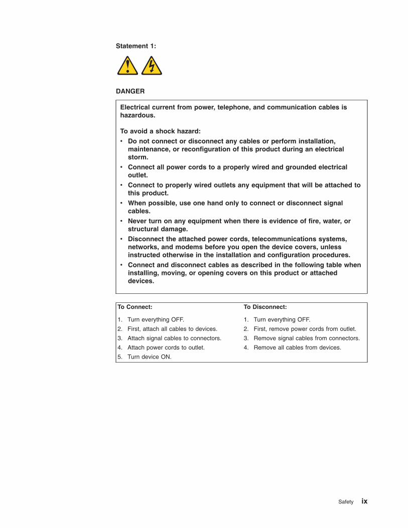
Statement 1:
DANGER
Electrical current from power, telephone, and communication cables is
hazardous.
To avoid a shock hazard:
v Do not connect or disconnect any cables or perform installation,
maintenance, or reconfiguration of this product during an electrical
storm.
v Connect all power cords to a properly wired and grounded electrical
outlet.
v Connect to properly wired outlets any equipment that will be attached to
this product.
v When possible, use one hand only to connect or disconnect signal
cables.
v Never turn on any equipment when there is evidence of fire, water, or
structural damage.
v Disconnect the attached power cords, telecommunications systems,
networks, and modems before you open the device covers, unless
instructed otherwise in the installation and configuration procedures.
v Connect and disconnect cables as described in the following table when
installing, moving, or opening covers on this product or attached
devices.
To Connect: To Disconnect:
1. Turn everything OFF.
2. First, attach all cables to devices.
3. Attach signal cables to connectors.
4. Attach power cords to outlet.
5. Turn device ON.
1. Turn everything OFF.
2. First, remove power cords from outlet.
3. Remove signal cables from connectors.
4. Remove all cables from devices.
Safety ix
Statement 2:
CAUTION:
When replacing the lithium battery, use only IBM Part Number 33F8354 or an
equivalent type battery recommended by the manufacturer. If your system has
a module containing a lithium battery, replace it only with the same module
type made by the same manufacturer. The battery contains lithium and can
explode if not properly used, handled, or disposed of.
Do not:
v Throw or immerse into water
v Heat to more than 100°C (212°F)
v Repair or disassemble
Dispose of the battery as required by local ordinances or regulations.
x IBM System x3500 Type 7977: Problem Determination and Service Guide
Statement 3:
CAUTION:
When laser products (such as CD-ROMs, DVD drives, fiber optic devices, or
transmitters) are installed, note the following:
v Do not remove the covers. Removing the covers of the laser product could
result in exposure to hazardous laser radiation. There are no serviceable
parts inside the device.
v Use of controls or adjustments or performance of procedures other than
those specified herein might result in hazardous radiation exposure.
DANGER
Some laser products contain an embedded Class 3A or Class 3B laser
diode. Note the following.
Laser radiation when open. Do not stare into the beam, do not view directly
with optical instruments, and avoid direct exposure to the beam.
Class 1 Laser ProductLaser Klasse 1Laser Klass 1Luokan 1 LaserlaiteAppareil A Laser de Classe 1`
Safety xi
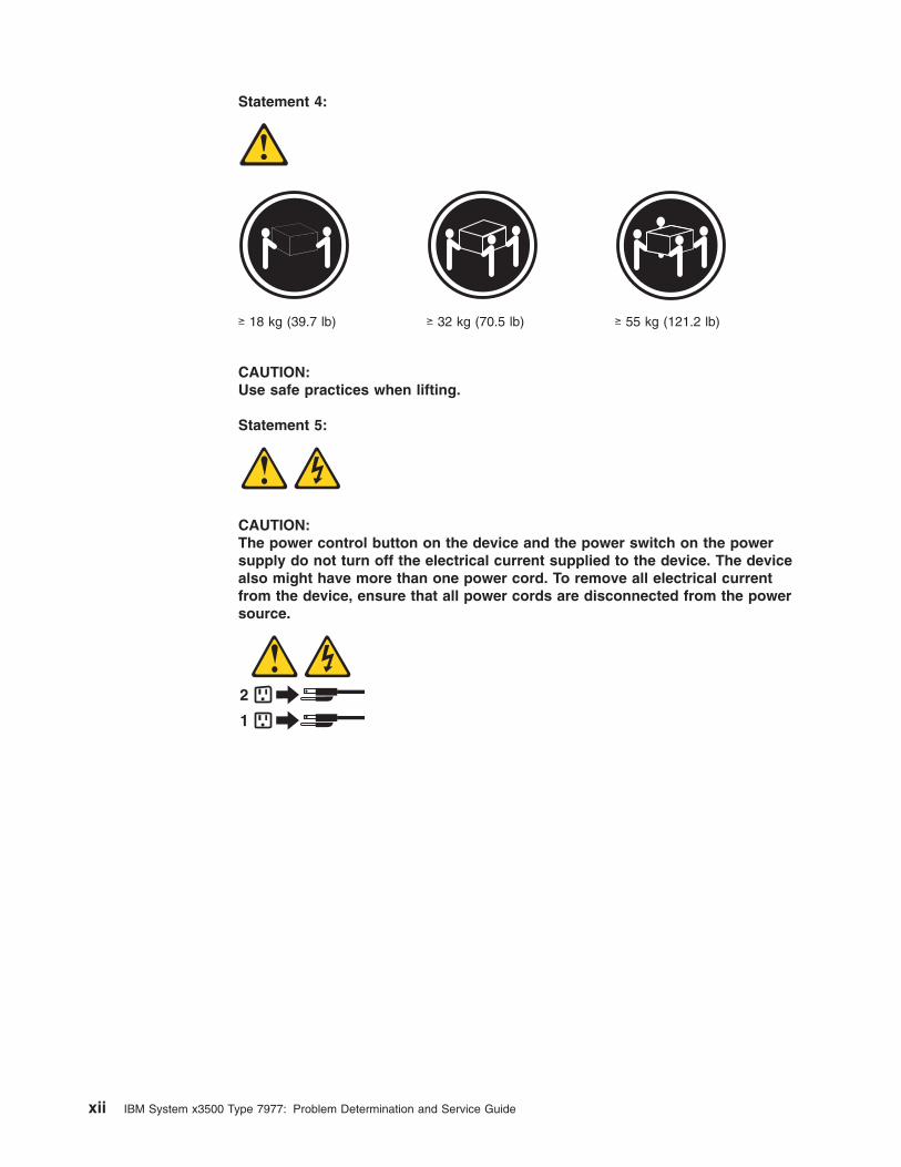
Statement 4:
≥ 18 kg (39.7 lb) ≥ 32 kg (70.5 lb) ≥ 55 kg (121.2 lb)
CAUTION:
Use safe practices when lifting.
Statement 5:
CAUTION:
The power control button on the device and the power switch on the power
supply do not turn off the electrical current supplied to the device. The device
also might have more than one power cord. To remove all electrical current
from the device, ensure that all power cords are disconnected from the power
source.
1
2
xii IBM System x3500 Type 7977: Problem Determination and Service Guide
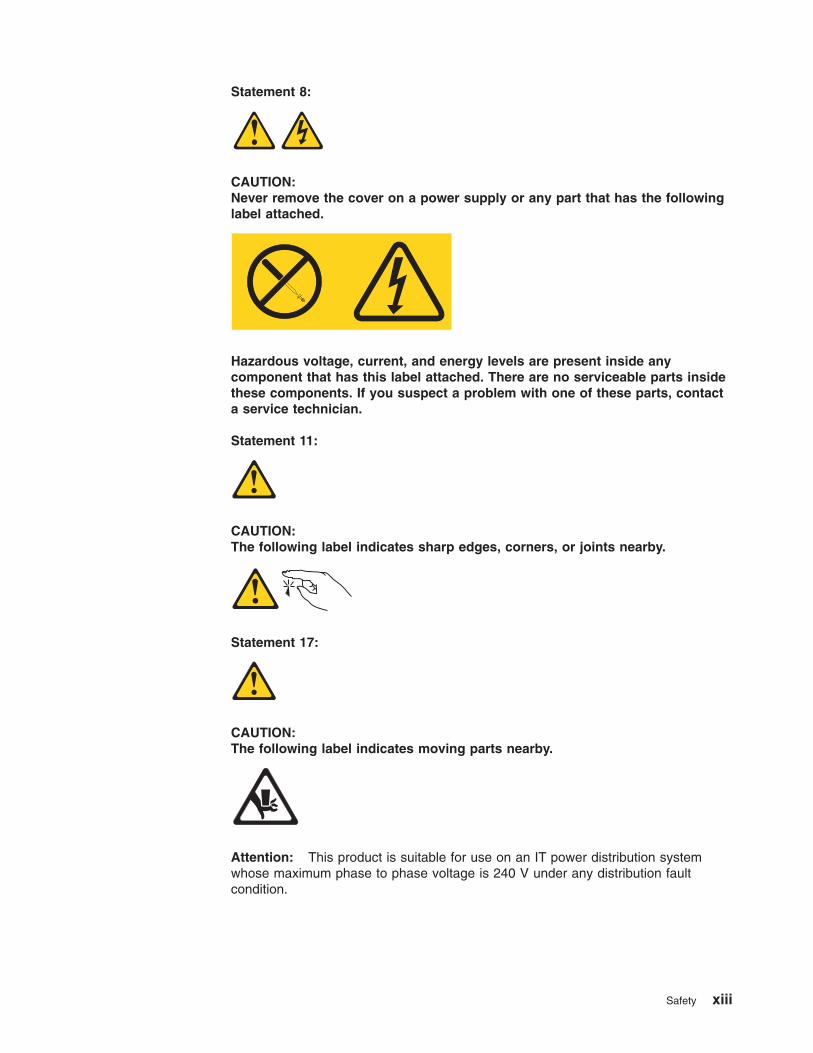
Statement 8:
CAUTION:
Never remove the cover on a power supply or any part that has the following
label attached.
Hazardous voltage, current, and energy levels are present inside any
component that has this label attached. There are no serviceable parts inside
these components. If you suspect a problem with one of these parts, contact
a service technician.
Statement 11:
CAUTION:
The following label indicates sharp edges, corners, or joints nearby.
Statement 17:
CAUTION:
The following label indicates moving parts nearby.
Attention: This product is suitable for use on an IT power distribution system
whose maximum phase to phase voltage is 240 V under any distribution fault
condition.
Safety xiii

xiv IBM System x3500 Type 7977: Problem Determination and Service Guide
Chapter 1. Introduction
This Problem Determination and Service Guide contains information to help you
solve problems that might occur in your IBM® System x3500 Type 7977 server. It
describes the diagnostic tools that come with the server, error codes and suggested
actions, and instructions for replacing failing components.
Replaceable components are of three types:
v Tier 1 customer replaceable unit (CRU): Replacement of Tier 1 CRUs is your
responsibility. If IBM installs a Tier 1 CRU at your request, you will be charged for
the installation.
v Tier 2 customer replaceable unit: You may install a Tier 2 CRU yourself or
request IBM to install it, at no additional charge, under the type of warranty
service that is designated for your server.
v Field replaceable unit (FRU): FRUs must be installed only by trained service
technicians.
For information about the terms of the warranty and getting service and assistance,
see the Warranty and Support Information document.
Related documentation
In addition to this document, the following documentation also comes with the
server:
v Installation Guide
This printed document contains instructions for setting up the server and basic
instructions for installing some options.
v User’s Guide
This document is in Portable Document Format (PDF) on the IBM Documentation
CD. It provides general information about the server, including information about
features, and how to configure the server. It also contains detailed instructions for
installing, removing, and connecting optional devices that the server supports.
v Rack Installation Instructions
This printed document contains instructions for installing the server in a rack.
v Safety Information
This document is in PDF on the IBM Documentation CD. It contains translated
caution and danger statements. Each caution and danger statement that appears
in the documentation has a number that you can use to locate the corresponding
statement in your language in the Safety Information document.
v Warranty and Support Information
This document is in PDF on the Documentation CD. It contains information about
the terms of the warranty and getting service and assistance.
Depending on the server model, additional documentation might be included on the
IBM Documentation CD.
The server might have features that are not described in the documentation that
comes with the server. The documentation might be updated occasionally to include
information about those features, or technical updates might be available to provide
additional information that is not included in the server documentation. These
© Copyright IBM Corp. 2007 1
updates are available from the IBM Web site. To check for updated documentation
and technical updates, complete the following steps.
Note: Changes are made periodically to the IBM Web site. The actual procedure
might vary slightly from what is described in this document.
1. Go to http://www.ibm.com/support/.
2. Under Search technical support, type IBM System x3500, and click Search.
Notices and statements in this document
The caution and danger statements that appear in this document are also in the
multilingual Safety Information document, which is on the IBM Documentation CD.
Each statement is numbered for reference to the corresponding statement in the
Safety Information document.
The following notices and statements are used in this document:
v Note: These notices provide important tips, guidance, or advice.
v Important: These notices provide information or advice that might help you avoid
inconvenient or problem situations.
v Attention: These notices indicate potential damage to programs, devices, or
data. An attention notice is placed just before the instruction or situation in which
damage could occur.
v Caution: These statements indicate situations that can be potentially hazardous
to you. A caution statement is placed just before the description of a potentially
hazardous procedure step or situation.
v Danger: These statements indicate situations that can be potentially lethal or
extremely hazardous to you. A danger statement is placed just before the
description of a potentially lethal or extremely hazardous procedure step or
situation.
2 IBM System x3500 Type 7977: Problem Determination and Service Guide
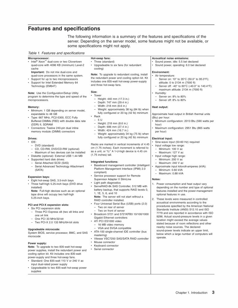
Features and specifications
The following information is a summary of the features and specifications of the
server. Depending on the server model, some features might not be available, or
some specifications might not apply.
Table 1. Features and specifications
Microprocessor:
v Intel® Xeon™ dual-core or two Clovertown
quad-core with 4096 KB (minimum) Level-2
cache
Important: Do not mix dual-core and
quad-core processors in the same system.
v Support for up to two microprocessors
v Support for Intel Extended Memory 64
Technology (EM64T)
Note: Use the Configuration/Setup Utility
program to determine the type and speed of the
microprocessors.
Memory:
v Minimum: 1 GB depending on server model,
expandable to 48 GB
v Type: 667 MHz, PC2-5300, ECC Fully
Buffered DIMMs (FBD) with double data rate
(DDR) II, SDRAM
v Connectors: Twelve 240-pin dual inline
memory module (DIMM) connectors
Drives:
v IDE:
– DVD (standard)
– CD, CD-RW, DVD/CD-RW (optional)
– Maximum of two devices can be installedv Diskette (optional): External USB 1.44 MB
v Supported hard disk drives:
– Serial Attached SCSI (SAS)
– Serial Advanced Technology Attachment
(SATA)
Expansion bays:
v Eight hot-swap SAS, 3.5-inch bays
v Three half-high 5.25-inch bays (DVD drive
installed)
Note: Full-high devices such as an optional
tape drive will occupy two half-high
5.25-inch bays.
PCI and PCI-X expansion slots:
v Six PCI expansion slots
– Three PCI Express x8 (two x8 links and
one x4 link
– One PCI 33 MHz/32-bit
– Two PCI-X 2.0 133 MHz/64-bit slots
Upgradeable microcode:
System BIOS, service processor, BMC, and SAS
microcode
Power supply:
Note: To upgrade to two 835-watt hot-swap
power supplies, install the redundant power and
cooling option kit. Kit includes one 835-watt
power-supply and three hot-swap fans.
v Standard: One 835-watt 110 V or 240 V ac
input dual-rated power supply
v Upgradeable to two 835-watt hot-swap power
supplies
Hot-swap fans:
v Three (standard)
v Upgradeable to six fans (for redundant
cooling)
Note: To upgrade to redundant cooling, install
the redundant power and cooling option kit. Kit
includes one 835-watt hot-swap power-supply
and three hot-swap fans.
Size:
v Tower
– Height: 440 mm (17.3 in.)
– Depth: 747 mm (29.4 in.)
– Width: 218 mm (8.6 in.)
– Weight: approximately 38 kg (84 lb) when
fully configured or 20 kg (42 lb) minimumv Rack
– 5 U
– Height: 218 mm (8.6 in.)
– Depth: 696 mm (27.4 in.)
– Width: 424 mm (16.7 in.)
– Weight: approximately 34 kg (75 lb) when
fully configured or 20 kg (42 lb) minimum
Racks are marked in vertical increments of 4.45
cm (1.75 inches). Each increment is referred to
as a unit, or “U.” A 1-U-high device is 4.45 cm
(1.75 inches) tall.
Integrated functions:
v Baseboard management controller (Intelligent
Platform Management Interface (IPMI) 2.0
compliant)
v Service processor support for Remote
Supervisor Adapter II SlimLine
v Light path diagnostics
v ServeRAID-8k SAS Controller, 512 MB with
battery backup, that supports RAID levels 0,
1, 1E, 5, 6, and 10
Note: The server will not start without a
RAID controller installed.
v Four Universal Serial Bus (USB) ports (2.0)
– Two on rear of server
– Two on front of serverv Broadcom 5721 and 5721KFB3 10/100/1000
Gigabit Ethernet controllers
v ATI PCI ES1000 video
– 16 MB video memory
– VGA and SVGA compatiblev ATA-100 single-channel IDE controller (bus
mastering)
v Vitesse VSC7250 SAS/SATA RAID controller
v Mouse connector
v Keyboard connector
v Serial connector
Acoustical noise emissions:
v Sound power, idle: 5.5 bel declared
v Sound power, operating: 6.0 bel declared
Environment:
v Air temperature:
– Server on: 10° to 35°C (50.0° to 95.0°F);
altitude: 0 to 2134 m (7000 ft)
– Server off: -40° to 60°C (-40.0° to 140.4°F);
maximum altitude: 2134 m (7000 ft)v Humidity:
– Server on: 8% to 80%
– Server off: 8% to 80%
Heat output:
Approximate heat output in British thermal units
(Btu) per hour:
v Minimum configuration: 2013 Btu (590 watts per
hour)
v Maximum configuration: 2951 Btu (865 watts
per hour)
Electrical input:
v Sine-wave input (50-60 Hz) required
v Input voltage low range:
– Minimum: 100 V ac
– Maximum: 127 V acv Input voltage high range:
– Minimum: 200 V ac
– Maximum: 240 V acv Approximate input kilovolt-amperes (kVA):
– Minimum: 0.60 kVA
– Maximum: 0.88 kVA
Notes:
1. Power consumption and heat output vary
depending on the number and type of optional
features installed and the power-management
optional features in use.
2. These levels were measured in controlled
acoustical environments according to the
procedures specified by the American National
Standards Institute (ANSI) S12.10 and ISO
7779 and are reported in accordance with ISO
9296. Actual sound-pressure levels in a given
location might exceed the average values
stated because of room reflections and other
nearby noise sources. The declared
sound-power levels indicate an upper limit,
below which a large number of computers will
operate.
Chapter 1. Introduction 3
Server controls, LEDs, and connectors
This section describes the controls, light-emitting diodes (LEDs), and connectors on
the front and rear of the server.
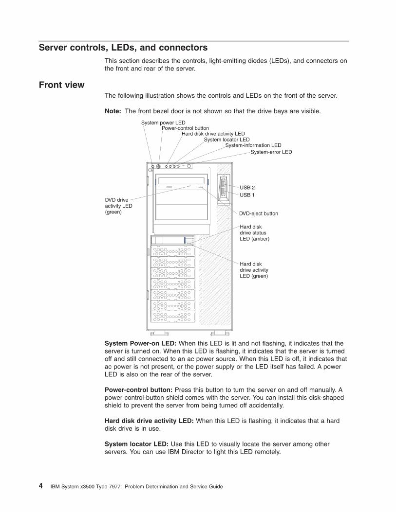
Front view
The following illustration shows the controls and LEDs on the front of the server.
Note: The front bezel door is not shown so that the drive bays are visible.
USB 2USB 1
Power-control button
DVD-eject button
DVD driveactivity LED(green)
System power LED
Hard disk drive activity LEDSystem locator LED
System-information LEDSystem-error LED
Hard diskdrive activityLED (green)
Hard diskdrive statusLED (amber)
System Power-on LED: When this LED is lit and not flashing, it indicates that the
server is turned on. When this LED is flashing, it indicates that the server is turned
off and still connected to an ac power source. When this LED is off, it indicates that
ac power is not present, or the power supply or the LED itself has failed. A power
LED is also on the rear of the server.
Power-control button: Press this button to turn the server on and off manually. A
power-control-button shield comes with the server. You can install this disk-shaped
shield to prevent the server from being turned off accidentally.
Hard disk drive activity LED: When this LED is flashing, it indicates that a hard
disk drive is in use.
System locator LED: Use this LED to visually locate the server among other
servers. You can use IBM Director to light this LED remotely.
4 IBM System x3500 Type 7977: Problem Determination and Service Guide
System-information LED: When this amber LED is on, the server power supplies
are nonredundant, or some other noncritical event has occurred. The event is
recorded in the error log. Check the light path diagnostic panel for more information.
System-error LED: When this amber LED is lit, it indicates that a system error has
occurred. Use the diagnostic LED panel and the system service label on the inside
of the left-side cover to further isolate the error.
USB 1: Connect a USB device to this connector.
USB 2: Connect a USB device to this connector.
DVD-eject button: Press this button to release a CD or DVD from the DVD drive.
Hard disk drive status LED: When this LED is lit, it indicates that the associated
hard disk drive has failed. If an optional RAID adapter is installed in the server and
the LED flashes slowly (one flash per second), the drive is being rebuilt. If the LED
flashes rapidly (three flashes per second), the controller is identifying the drive.
Hard disk drive activity LED: When this LED is flashing, it indicates that the drive
is in use.
Hard disk drive status LED: On some server models, each hot-swap hard disk
drive has a status LED. When this LED is lit, it indicates that the drive has failed. If
an optional IBM ServeRAID controller is installed in the server, when this LED is
flashing slowly (one flash per second), it indicates that the drive is being rebuilt.
When the LED is flashing rapidly (three flashes per second), it indicates that the
controller is identifying the drive.
DVD drive activity LED: When this LED is lit, it indicates that the DVD drive is in
use.
Chapter 1. Introduction 5
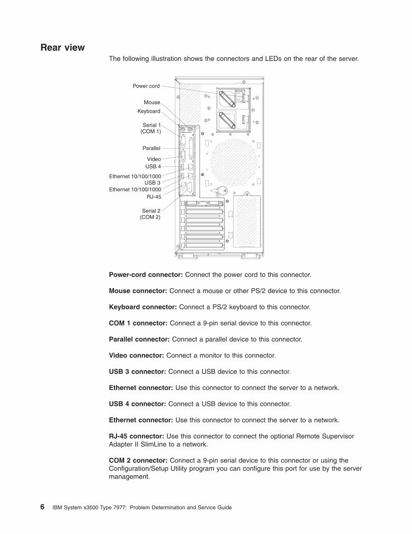
Rear view
The following illustration shows the connectors and LEDs on the rear of the server.
Video
Mouse
Power cord
Keyboard
Serial 1(COM 1)
Parallel
Serial 2(COM 2)
USB 4
Ethernet 10/100/1000
Ethernet 10/100/1000RJ-45
USB 3
Power-cord connector: Connect the power cord to this connector.
Mouse connector: Connect a mouse or other PS/2 device to this connector.
Keyboard connector: Connect a PS/2 keyboard to this connector.
COM 1 connector: Connect a 9-pin serial device to this connector.
Parallel connector: Connect a parallel device to this connector.
Video connector: Connect a monitor to this connector.
USB 3 connector: Connect a USB device to this connector.
Ethernet connector: Use this connector to connect the server to a network.
USB 4 connector: Connect a USB device to this connector.
Ethernet connector: Use this connector to connect the server to a network.
RJ-45 connector: Use this connector to connect the optional Remote Supervisor
Adapter II SlimLine to a network.
COM 2 connector: Connect a 9-pin serial device to this connector or using the
Configuration/Setup Utility program you can configure this port for use by the server
management.
6 IBM System x3500 Type 7977: Problem Determination and Service Guide
Note: When this connector is configured for use with the server management, do
not connect any other 9-pin serial devices to this connector.
Chapter 1. Introduction 7
Internal LEDs, connectors, and jumpers
The illustrations in this section show the LEDs, connectors, and jumpers on the
internal boards. The illustrations might differ slightly from your hardware.
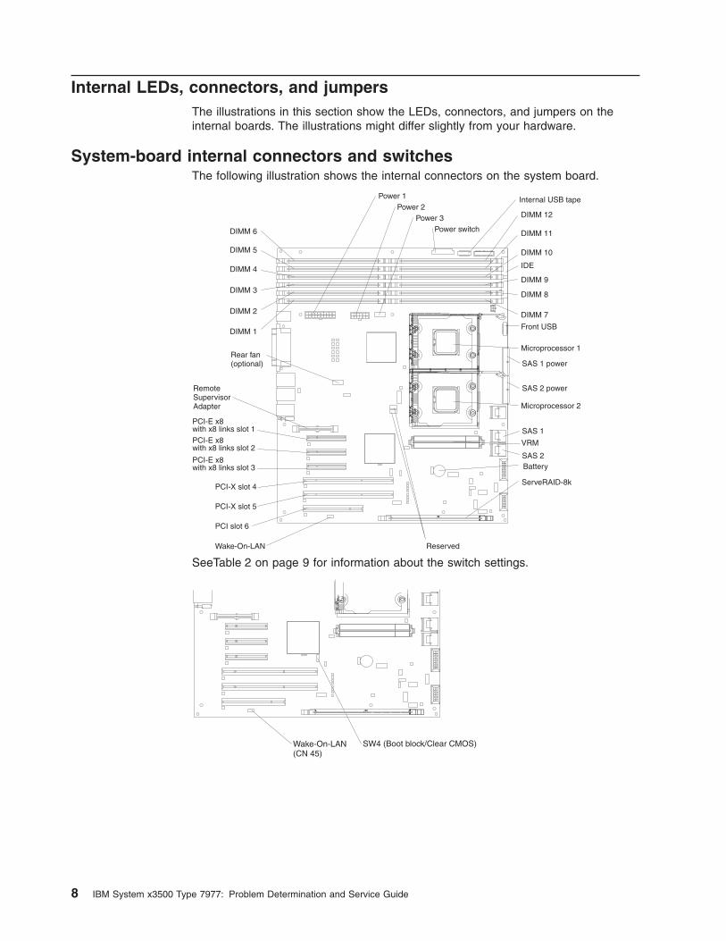
System-board internal connectors and switches
The following illustration shows the internal connectors on the system board.
DIMM 12
DIMM 6 DIMM 11
DIMM 5 DIMM 10
IDEDIMM 4DIMM 9
DIMM 3 DIMM 8
DIMM 2 DIMM 7
DIMM 1
Microprocessor 1
Microprocessor 2
VRM
Battery
ServeRAID-8k
PCI slot 6
PCI-X slot 5
PCI-X slot 4
PCI-E x8with x8 links slot 1PCI-E x8with x8 links slot 2
PCI-E x8with x8 links slot 3
RemoteSupervisorAdapter
Power 1Power 2
Power 3Power switch
SAS 2
SAS 2 power
SAS 1
SAS 1 powerRear fan(optional)
Reserved
Front USB
Internal USB tape
Wake-On-LAN
SeeTable 2 on page 9 for information about the switch settings.
Wake-On-LAN(CN 45)
SW4 (Boot block/Clear CMOS)
8 IBM System x3500 Type 7977: Problem Determination and Service Guide
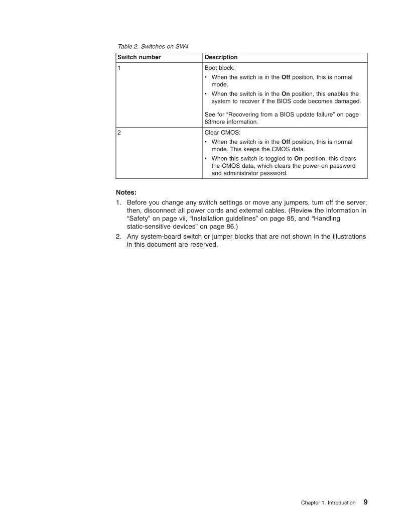
Table 2. Switches on SW4
Switch number Description
1 Boot block:
v When the switch is in the Off position, this is normal
mode.
v When the switch is in the On position, this enables the
system to recover if the BIOS code becomes damaged.
See for “Recovering from a BIOS update failure” on page
63more information.
2 Clear CMOS:
v When the switch is in the Off position, this is normal
mode. This keeps the CMOS data.
v When this switch is toggled to On position, this clears
the CMOS data, which clears the power-on password
and administrator password.
Notes:
1. Before you change any switch settings or move any jumpers, turn off the server;
then, disconnect all power cords and external cables. (Review the information in
“Safety” on page vii, “Installation guidelines” on page 85, and “Handling
static-sensitive devices” on page 86.)
2. Any system-board switch or jumper blocks that are not shown in the illustrations
in this document are reserved.
Chapter 1. Introduction 9
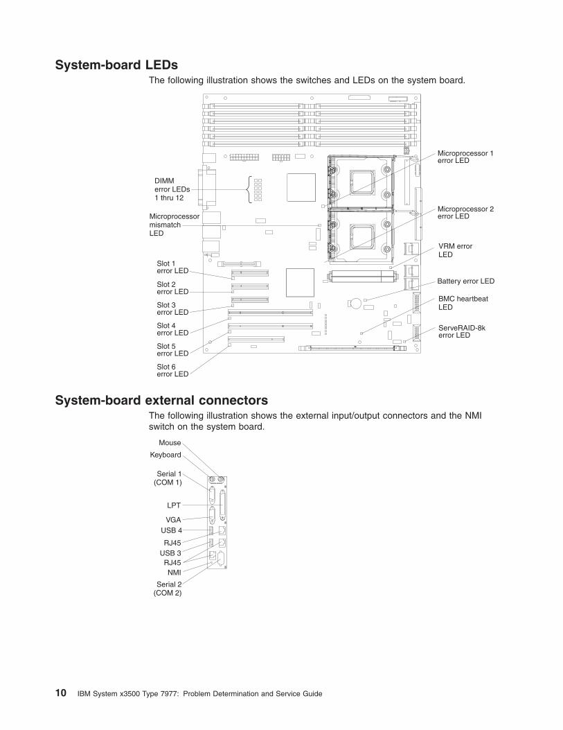
System-board LEDs
The following illustration shows the switches and LEDs on the system board.
Slot 1error LED
Slot 2error LED
Slot 3error LED
Slot 4error LED
Slot 5error LED
Slot 6error LED
MicroprocessormismatchLED
DIMMerror LEDs1 thru 12
Microprocessor 1error LED
Microprocessor 2error LED
VRM errorLED
BMC heartbeatLED
ServeRAID-8kerror LED
Battery error LED
System-board external connectors
The following illustration shows the external input/output connectors and the NMI
switch on the system board.
Mouse
Keyboard
Serial 1(COM 1)
VGA
LPT
Serial 2(COM 2)
USB 4
RJ45
RJ45NMI
USB 3
10 IBM System x3500 Type 7977: Problem Determination and Service Guide
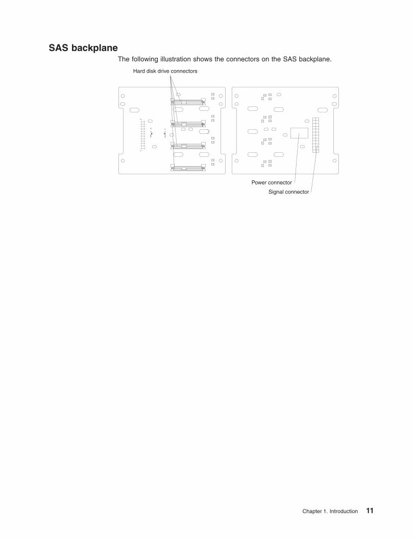
SAS backplane
The following illustration shows the connectors on the SAS backplane.
Hard disk drive connectors
Signal connector
Power connector
Chapter 1. Introduction 11

12 IBM System x3500 Type 7977: Problem Determination and Service Guide
Chapter 2. Diagnostics
This chapter describes the diagnostic tools that are available to help you solve
problems that might occur in the server.
If you cannot locate and correct the problem using the information in this chapter,
see Appendix A, “Getting help and technical assistance,” on page 127 for more
information.
Diagnostic tools
The following tools are available to help you diagnose and solve hardware-related
problems:
v POST beep codes, error messages, and error logs
The power-on self-test (POST) generates beep codes and messages to indicate
successful test completion or the detection of a problem. See “POST” for more
information.
v Troubleshooting tables
These tables list problem symptoms and actions to correct the problems. See
“Troubleshooting tables” on page 32.
v Light path diagnostics
Use the light path diagnostics to diagnose system errors quickly. See “Light path
diagnostics” on page 45 for more information.
v Diagnostic programs, messages, and error codes
The diagnostic programs are the primary method of testing the major
components of the server. The diagnostic programs are on the IBM Enhanced
Diagnostics CD that comes with the server. See “Diagnostic programs,
messages, and error codes” on page 52 for more information.
POST
When you turn on the server, it performs a series of tests to check the operation of
the server components and some optional devices in the server. This series of tests
is called the power-on self-test, or POST.
If a power-on password is set, you must type the password and press Enter, when
prompted, for POST to run.
If POST is completed without detecting any problems, a single beep sounds, and
the server startup is completed.
If POST detects a problem, more than one beep might sound, or an error message
is displayed. See “Beep code descriptions” on page 14 and “POST error codes” on
page 20 for more information.
POST beep codes
A beep code is a combination of short or long beeps or series of short beeps that
are separated by pauses. For example, a “1-2-3” beep code is one short beep, a
pause, two short beeps, and pause, and three short beeps. A beep code other than
one beep indicates that POST has detected a problem. To determine the meaning
of a beep code, see “Beep code descriptions” on page 14. If no beep code sounds,
see “No-beep symptoms” on page 18.
© Copyright IBM Corp. 2007 13
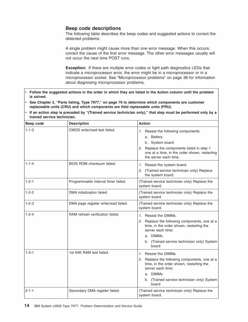
Beep code descriptions
The following table describes the beep codes and suggested actions to correct the
detected problems.
A single problem might cause more than one error message. When this occurs,
correct the cause of the first error message. The other error messages usually will
not occur the next time POST runs.
Exception: If there are multiple error codes or light path diagnostics LEDs that
indicate a microprocessor error, the error might be in a microprocessor or in a
microprocessor socket. See “Microprocessor problems” on page 38 for information
about diagnosing microprocessor problems.
v Follow the suggested actions in the order in which they are listed in the Action column until the problem
is solved.
v See Chapter 3, “Parts listing, Type 7977,” on page 79 to determine which components are customer
replaceable units (CRU) and which components are field replaceable units (FRU).
v If an action step is preceded by “(Trained service technician only),” that step must be performed only by a
trained service technician.
Beep code Description Action
1-1-3 CMOS write/read test failed. 1. Reseat the following components:
a. Battery
b. System board
2. Replace the components listed in step 1
one at a time, in the order shown, restarting
the server each time.
1-1-4 BIOS ROM checksum failed. 1. Reseat the system board.
2. (Trained service technician only) Replace
the system board.
1-2-1 Programmable interval timer failed. (Trained service technician only) Replace the
system board.
1-2-2 DMA initialization failed. (Trained service technician only) Replace the
system board.
1-2-3 DMA page register write/read failed. (Trained service technician only) Replace the
system board.
1-2-4 RAM refresh verification failed. 1. Reseat the DIMMs.
2. Replace the following components, one at a
time, in the order shown, restarting the
server each time:
a. DIMMs
b. (Trained service technician only) System
board
1-3-1 1st 64K RAM test failed. 1. Reseat the DIMMs.
2. Replace the following components, one at a
time, in the order shown, restarting the
server each time:
a. DIMMs
b. (Trained service technician only) System
board
2-1-1 Secondary DMA register failed. (Trained service technician only) Replace the
system board.
14 IBM System x3500 Type 7977: Problem Determination and Service Guide
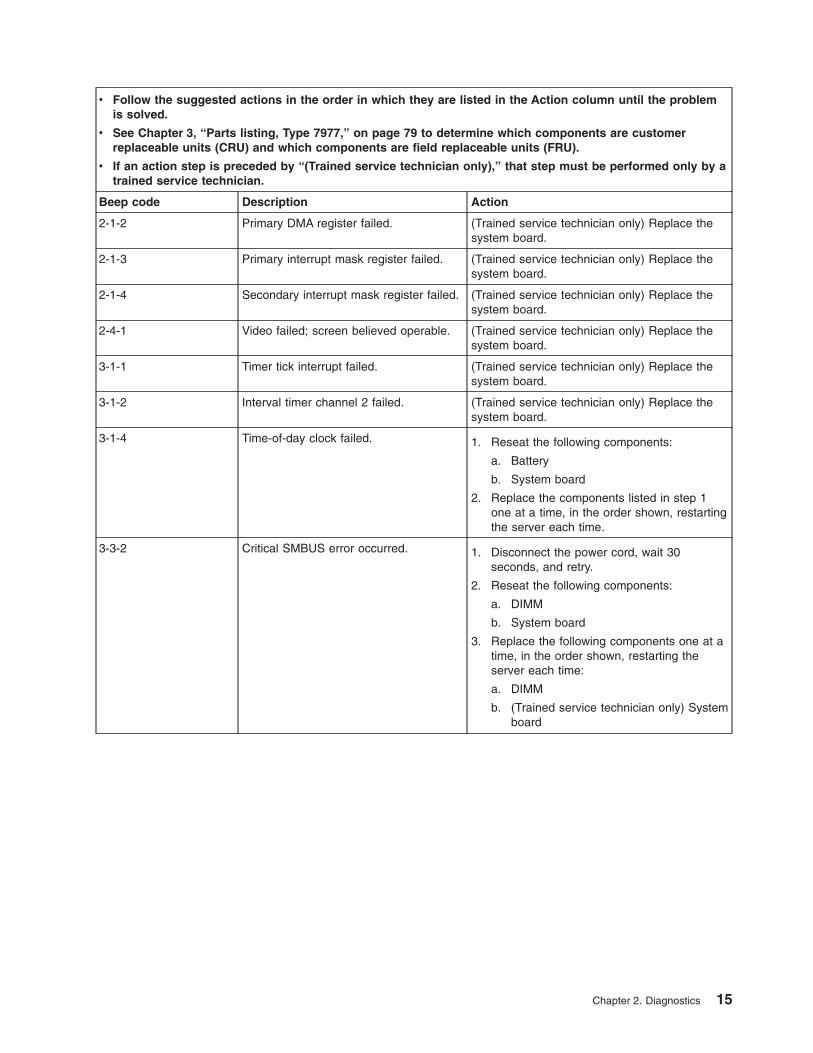
v Follow the suggested actions in the order in which they are listed in the Action column until the problem
is solved.
v See Chapter 3, “Parts listing, Type 7977,” on page 79 to determine which components are customer
replaceable units (CRU) and which components are field replaceable units (FRU).
v If an action step is preceded by “(Trained service technician only),” that step must be performed only by a
trained service technician.
Beep code Description Action
2-1-2 Primary DMA register failed. (Trained service technician only) Replace the
system board.
2-1-3 Primary interrupt mask register failed. (Trained service technician only) Replace the
system board.
2-1-4 Secondary interrupt mask register failed. (Trained service technician only) Replace the
system board.
2-4-1 Video failed; screen believed operable. (Trained service technician only) Replace the
system board.
3-1-1 Timer tick interrupt failed. (Trained service technician only) Replace the
system board.
3-1-2 Interval timer channel 2 failed. (Trained service technician only) Replace the
system board.
3-1-4 Time-of-day clock failed. 1. Reseat the following components:
a. Battery
b. System board
2. Replace the components listed in step 1
one at a time, in the order shown, restarting
the server each time.
3-3-2 Critical SMBUS error occurred. 1. Disconnect the power cord, wait 30
seconds, and retry.
2. Reseat the following components:
a. DIMM
b. System board
3. Replace the following components one at a
time, in the order shown, restarting the
server each time:
a. DIMM
b. (Trained service technician only) System
board
Chapter 2. Diagnostics 15
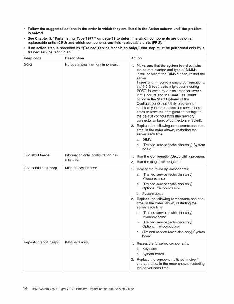
v Follow the suggested actions in the order in which they are listed in the Action column until the problem
is solved.
v See Chapter 3, “Parts listing, Type 7977,” on page 79 to determine which components are customer
replaceable units (CRU) and which components are field replaceable units (FRU).
v If an action step is preceded by “(Trained service technician only),” that step must be performed only by a
trained service technician.
Beep code Description Action
3-3-3 No operational memory in system. 1. Make sure that the system board contains
the correct number and type of DIMMs;
install or reseat the DIMMs; then, restart the
server.
Important: In some memory configurations,
the 3-3-3 beep code might sound during
POST, followed by a blank monitor screen.
If this occurs and the Boot Fail Count
option in the Start Options of the
Configuration/Setup Utility program is
enabled, you must restart the server three
times to reset the configuration settings to
the default configuration (the memory
connector or bank of connectors enabled).
2. Replace the following components one at a
time, in the order shown, restarting the
server each time:
a. DIMM
b. (Trained service technician only) System
board
Two short beeps Information only, configuration has
changed.
1. Run the Configuration/Setup Utility program.
2. Run the diagnostic programs.
One continuous beep Microprocessor error. 1. Reseat the following components:
a. (Trained service technician only)
Microprocessor
b. (Trained service technician only)
Optional microprocessor
c. System board
2. Replace the following components one at a
time, in the order shown, restarting the
server each time.
a. (Trained service technician only)
Microprocessor
b. (Trained service technician only)
Optional microprocessor
c. (Trained service technician only) System
board
Repeating short beeps Keyboard error. 1. Reseat the following components:
a. Keyboard
b. System board
2. Replace the components listed in step 1
one at a time, in the order shown, restarting
the server each time.
16 IBM System x3500 Type 7977: Problem Determination and Service Guide
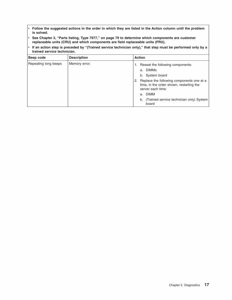
v Follow the suggested actions in the order in which they are listed in the Action column until the problem
is solved.
v See Chapter 3, “Parts listing, Type 7977,” on page 79 to determine which components are customer
replaceable units (CRU) and which components are field replaceable units (FRU).
v If an action step is preceded by “(Trained service technician only),” that step must be performed only by a
trained service technician.
Beep code Description Action
Repeating long beeps Memory error. 1. Reseat the following components:
a. DIMMs
b. System board
2. Replace the following components one at a
time, in the order shown, restarting the
server each time:
a. DIMM
b. (Trained service technician only) System
board
Chapter 2. Diagnostics 17
No-beep symptoms
The following table describes situations in which no beep code sounds when POST
is completed.
v Follow the suggested actions in the order in which they are listed in the Action column until the problem
is solved.
v See Chapter 3, “Parts listing, Type 7977,” on page 79 to determine which components are customer
replaceable units (CRU) and which components are field replaceable units (FRU).
v If an action step is preceded by “(Trained service technician only),” that step must be performed only by a
trained service technician.
No-beep symptom Description Action
No beeps occur, and the
server operates correctly.
1. (Trained service technician only) Reseat the
operator information LED cable.
2. (Trained service technician only) Replace
the operator information LED assembly.
No beeps occur after
successful completion of
POST.
The power-on status is Disabled. 1. Run the Configuration/Setup Utility program
and select Start Options; then, set
Power-On Status to Enable.
2. (Trained service technician only) Reseat the
operator information LED assembly.
3. (Trained service technician only) Replace
the operator information LED assembly.
No beeps occur, and
there is no video.
See “Solving undetermined problems” on page
76.
Error logs
The POST error log contains the three most recent error codes and messages that
were generated during POST. The BMC log and the system-error log contain
messages that were generated during POST and all system status messages from
the service processor.
The following illustration shows an example of a BMC log entry.
BMC System Event Log
----------------------------------------------------------
Get Next Entry
Get Previous Entry
Clear BMC SEL
Entry Number= 00005 / 00011
Record ID= 0005
Record Type= 02
Timestamp= 2005/01/25 16:15:17
Entry Details: Generator ID= 0020
Sensor Type= 04
Assertion Event
Fan
Threshold
Lower Non-critical - going high
Sensor Number= 40
Event Direction/Type= 01
Event Data= 52 00 1A
18 IBM System x3500 Type 7977: Problem Determination and Service Guide
The BMC log is limited in size. When the log is full, new entries will not overwrite
existing entries; therefore, you must periodically clear the BMC log through the
Configuration/Setup Utility program (the menu choices are described in the User’s
Guide). When you are troubleshooting an error, be sure to clear the BMC log so
that you can find current errors more easily.
Entries that are written to the BMC log during the early phase of POST show an
incorrect date and time as the default time stamp; however, the date and time are
corrected as POST continues.
Each BMC log entry appears on its own page. To display all the data for an entry,
use the Up Arrow (↑) and Down Arrow (↓) keys or the Page Up and Page Down
keys. To move from one entry to the next, select Get Next Entry or Get Previous
Entry.
The log indicates an assertion event when an event has occurred. It indicates a
deassertion event when the event is no longer occurring.
Some of the error codes and messages in the BMC log are abbreviated.
If you view the BMC log through the Web interface of the optional Remote
Supervisor Adapter II SlimLine, the messages can be translated.
You can view the contents of the POST error log, the BMC log, and the
system-error log from the Configuration/Setup Utility program. You can view the
contents of the BMC log also from the diagnostic programs.
When you are troubleshooting PCI-X slots, note that the error logs report the PCI-X
buses numerically. The numerical assignments vary depending on the configuration.
You can check the assignments by running the Configuration/Setup Utility program
(see the User’s Guide for more information).
Viewing error logs from the Configuration/Setup Utility program
For complete information about using the Configuration/Setup Utility program, see
the User’s Guide.
To view the error logs, complete the following steps:
1. Turn on the server.
2. When the prompt Press F1 for Configuration/Setup appears, press F1. If you
have set both a power-on password and an administrator password, you must
type the administrator password to view the error logs.
Note: If you forgot the power-on password or administrator password, you can
change the position of the jumper on pin 2 (boot block/clear CMOS) of SW4 to
theOn position to bypass the password check. This enables you to reset the
passwords.
3. Use one of the following procedures:
v To view the POST error log, select Error Logs, and then select POST Error
Log.
v To view the BMC log, select Advanced Settings, select Baseboard
Management Controller (BMC) settings, and then select BMC System
Event Log.
v To view the system-error log (available only if an optional Remote Supervisor
Adapter II SlimLine is installed), select Event/Error Logs, and then select
System Event/Error Log.
Chapter 2. Diagnostics 19
Viewing the BMC log from the diagnostic programs
The BMC log contains the same information, whether it is viewed from the
Configuration/Setup Utility program or from the diagnostic programs.
For information about using the diagnostic programs, see “Running the diagnostic
programs” on page 52.
To view the BMC log, complete the following steps:
1. If the server is running, turn off the server and all attached devices.
2. Turn on all attached devices; then, turn on the server.
3. When the prompt F1 for Configuration/Setup appears, press F1.
4. When the Configuration/Setup Utility menu appears, select Start Options.
5. From the Start Options menu, select Startup Sequence Options.
6. Note the device that is selected as the first startup device. Later, you must
restore this setting.
7. Select DVD-ROM as the first startup device.
8. Press Esc two times to return to the Configuration/Setup Utility menu.
9. Insert the IBM Enhanced Diagnostics CD in the CD drive.
10. Select Save & Exit Setup and follow the prompts. The diagnostics will load.
11. From the top of the screen, select Hardware Info.
12. From the list, select BMC Log.
POST error codes
The following table describes the POST error codes and suggested actions to
correct the detected problems.
v Follow the suggested actions in the order in which they are listed in the Action column until the problem
is solved.
v See Chapter 3, “Parts listing, Type 7977,” on page 79 to determine which components are customer
replaceable units (CRU) and which components are field replaceable units (FRU).
v If an action step is preceded by “(Trained service technician only),” that step must be performed only by a
trained service technician.
Error code Description Action
062 Three consecutive boot failures using the
default configuration.
1. Flash the system firmware to the latest level (see
“Updating the firmware” on page 117).
2. Reseat the system board.
3. Replace the system board.
101 Tick timer internal interrupt, internal timer
channel 2.
1. Reseat the system board.
2. Replace the system board.
102 Internal timer channel 2 test failure (Trained service technician only) Replace the system
board.
151 Real-time clock error. 1. Reseat the following components:
a. Battery
b. System board
2. Replace the components listed in step 1 one at a
time, in the order shown, restarting the server
each time.
20 IBM System x3500 Type 7977: Problem Determination and Service Guide
v Follow the suggested actions in the order in which they are listed in the Action column until the problem
is solved.
v See Chapter 3, “Parts listing, Type 7977,” on page 79 to determine which components are customer
replaceable units (CRU) and which components are field replaceable units (FRU).
v If an action step is preceded by “(Trained service technician only),” that step must be performed only by a
trained service technician.
Error code Description Action
161 Real-time clock battery error. 1. Reseat the following components:
a. Battery
b. System board
2. Replace the components listed in step 1 one at a
time, in the order shown, restarting the server
each time.
162 A device configuration has changed 1. Run the Configuration/Setup Utility program,
select Load Default Settings, and save the
settings.
2. Reseat the following components:
a. Battery
b. Failing device
c. System board
3. Replace the components listed in step 2 one at a
time, in the order shown, restarting the server
each time.
163 Real-time clock error. 1. Run the Configuration/Setup Utility program,
select Load Default Settings, make sure that the
date and time are correct, and save the settings.
2. Reseat the following components:
a. Battery
b. System board
3. Replace the components listed in step 2 one at a
time, in the order shown, restarting the server
each time.
175 Service processor flash code damaged or
not loaded.
Note: In this case, the service processor is
the optional Remote Supervisor Adapter II.
1. Update the Remote Supervisor Adapter II
firmware (see the Problem Determination and
Service Guide on the IBM System x
Documentation CD).
2. Replace the Remote Supervisor Adapter II.
184 Power-on password damaged. 1. Run the Configuration/Setup Utility program,
select Load Default Settings, and save the
settings.
2. Reseat the following components:
a. Battery
b. System board
3. Replace the components listed in step 2 one at a
time, in the order shown, restarting the server
each time.
Chapter 2. Diagnostics 21
v Follow the suggested actions in the order in which they are listed in the Action column until the problem
is solved.
v See Chapter 3, “Parts listing, Type 7977,” on page 79 to determine which components are customer
replaceable units (CRU) and which components are field replaceable units (FRU).
v If an action step is preceded by “(Trained service technician only),” that step must be performed only by a
trained service technician.
Error code Description Action
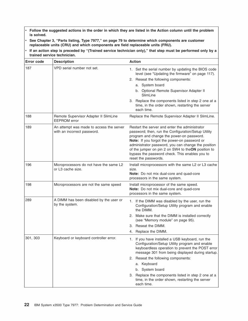
187 VPD serial number not set. 1. Set the serial number by updating the BIOS code
level (see “Updating the firmware” on page 117).
2. Reseat the following components:
a. System board
b. Optional Remote Supervisor Adapter II
SlimLine
3. Replace the components listed in step 2 one at a
time, in the order shown, restarting the server
each time.
188 Remote Supervisor Adapter II SlimLine
EEPROM error
Replace the Remote Supervisor Adapter II SlimLine.
189 An attempt was made to access the server
with an incorrect password.
Restart the server and enter the administrator
password; then, run the Configuration/Setup Utility
program and change the power-on password.
Note: If you forgot the power-on password or
administrator password, you can change the position
of the jumper on pin 2 on SW4 to theON position to
bypass the password check. This enables you to
reset the passwords.
196 Microprocessors do not have the same L2
or L3 cache size.
Install microprocessors with the same L2 or L3 cache
size.
Note: Do not mix dual-core and quad-core
processors in the same system.
198 Microprocessors are not the same speed Install microprocessor of the same speed.
Note: Do not mix dual-core and quad-core
processors in the same system.
289 A DIMM has been disabled by the user or
by the system.
1. If the DIMM was disabled by the user, run the
Configuration/Setup Utility program and enable
the DIMM.
2. Make sure that the DIMM is installed correctly
(see “Memory module” on page 95).
3. Reseat the DIMM.
4. Replace the DIMM.
301, 303 Keyboard or keyboard controller error. 1. If you have installed a USB keyboard, run the
Configuration/Setup Utility program and enable
keyboardless operation to prevent the POST error
message 301 from being displayed during startup.
2. Reseat the following components:
a. Keyboard
b. System board
3. Replace the components listed in step 2 one at a
time, in the order shown, restarting the server
each time.
22 IBM System x3500 Type 7977: Problem Determination and Service Guide
v Follow the suggested actions in the order in which they are listed in the Action column until the problem
is solved.
v See Chapter 3, “Parts listing, Type 7977,” on page 79 to determine which components are customer
replaceable units (CRU) and which components are field replaceable units (FRU).
v If an action step is preceded by “(Trained service technician only),” that step must be performed only by a
trained service technician.
Error code Description Action
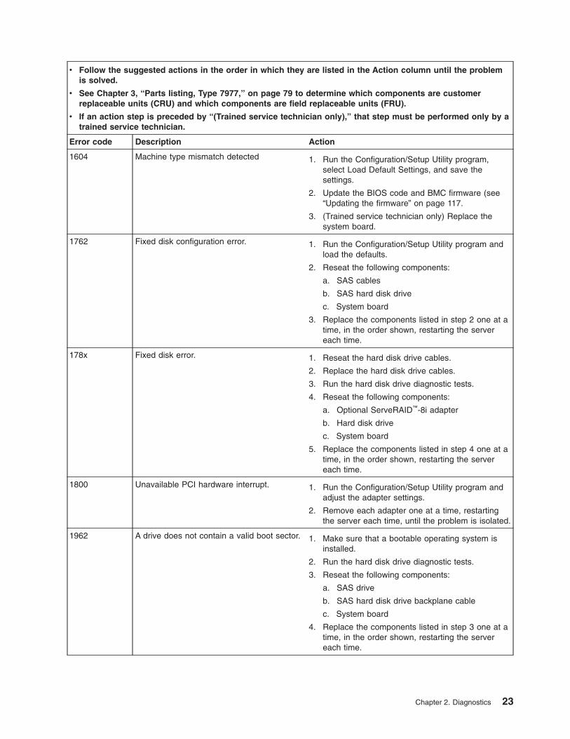
1604 Machine type mismatch detected 1. Run the Configuration/Setup Utility program,
select Load Default Settings, and save the
settings.
2. Update the BIOS code and BMC firmware (see
“Updating the firmware” on page 117.
3. (Trained service technician only) Replace the
system board.
1762 Fixed disk configuration error. 1. Run the Configuration/Setup Utility program and
load the defaults.
2. Reseat the following components:
a. SAS cables
b. SAS hard disk drive
c. System board
3. Replace the components listed in step 2 one at a
time, in the order shown, restarting the server
each time.
178x Fixed disk error. 1. Reseat the hard disk drive cables.
2. Replace the hard disk drive cables.
3. Run the hard disk drive diagnostic tests.
4. Reseat the following components:
a. Optional ServeRAID™-8i adapter
b. Hard disk drive
c. System board
5. Replace the components listed in step 4 one at a
time, in the order shown, restarting the server
each time.
1800 Unavailable PCI hardware interrupt. 1. Run the Configuration/Setup Utility program and
adjust the adapter settings.
2. Remove each adapter one at a time, restarting
the server each time, until the problem is isolated.
1962 A drive does not contain a valid boot sector. 1. Make sure that a bootable operating system is
installed.
2. Run the hard disk drive diagnostic tests.
3. Reseat the following components:
a. SAS drive
b. SAS hard disk drive backplane cable
c. System board
4. Replace the components listed in step 3 one at a
time, in the order shown, restarting the server
each time.
Chapter 2. Diagnostics 23
v Follow the suggested actions in the order in which they are listed in the Action column until the problem
is solved.
v See Chapter 3, “Parts listing, Type 7977,” on page 79 to determine which components are customer
replaceable units (CRU) and which components are field replaceable units (FRU).
v If an action step is preceded by “(Trained service technician only),” that step must be performed only by a
trained service technician.
Error code Description Action
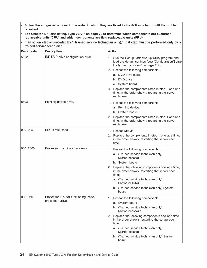
5962 IDE DVD drive configuration error. 1. Run the Configuration/Setup Utility program and
load the default settings (see “Configuration/Setup
Utility menu choices” on page 119).
2. Reseat the following components:
a. DVD drive cable
b. DVD drive
c. System board
3. Replace the components listed in step 2 one at a
time, in the order shown, restarting the server
each time.
8603 Pointing-device error. 1. Reseat the following components:
a. Pointing device
b. System board
2. Replace the components listed in step 1 one at a
time, in the order shown, restarting the server
each time.
0001295 ECC circuit check. 1. Reseat DIMMs
2. Replace the components in step 1 one at a time,
in the order shown, restarting the server each
time.
00012000 Processor machine check error. 1. Reseat the following components:
a. (Trained service technician only)
Microprocessor
b. System board
2. Replace the following components one at a time,
in the order shown, restarting the server each
time:
a. (Trained service technician only)
Microprocessor
b. (Trained service technician only) System
board
00019501 Processor 1 is not functioning; check
processor LEDs.
1. Reseat the following components:
a. System board
b. (Trained service technician only)
Microprocessor 1
2. Replace the following components one at a time,
in the order shown, restarting the server each
time:
a. (Trained service technician only)
Microprocessor 1
b. (Trained service technician only) System
board
24 IBM System x3500 Type 7977: Problem Determination and Service Guide
v Follow the suggested actions in the order in which they are listed in the Action column until the problem
is solved.
v See Chapter 3, “Parts listing, Type 7977,” on page 79 to determine which components are customer
replaceable units (CRU) and which components are field replaceable units (FRU).
v If an action step is preceded by “(Trained service technician only),” that step must be performed only by a
trained service technician.
Error code Description Action
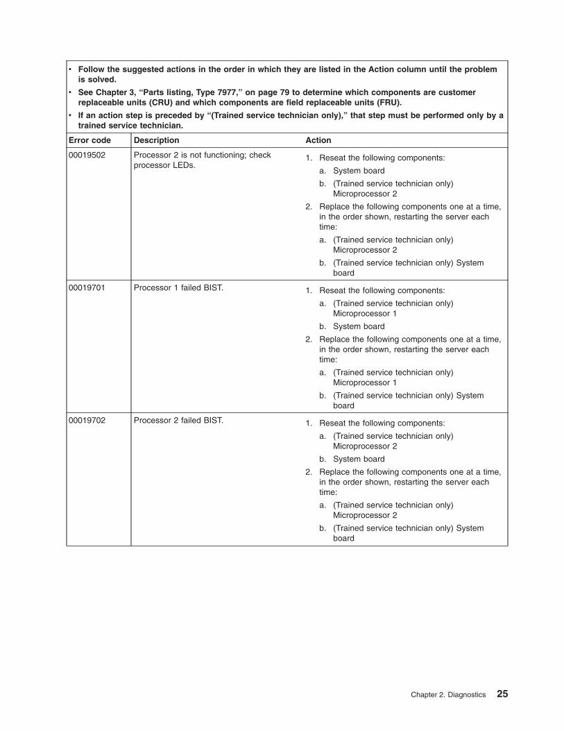
00019502 Processor 2 is not functioning; check
processor LEDs.
1. Reseat the following components:
a. System board
b. (Trained service technician only)
Microprocessor 2
2. Replace the following components one at a time,
in the order shown, restarting the server each
time:
a. (Trained service technician only)
Microprocessor 2
b. (Trained service technician only) System
board
00019701 Processor 1 failed BIST. 1. Reseat the following components:
a. (Trained service technician only)
Microprocessor 1
b. System board
2. Replace the following components one at a time,
in the order shown, restarting the server each
time:
a. (Trained service technician only)
Microprocessor 1
b. (Trained service technician only) System
board
00019702 Processor 2 failed BIST. 1. Reseat the following components:
a. (Trained service technician only)
Microprocessor 2
b. System board
2. Replace the following components one at a time,
in the order shown, restarting the server each
time:
a. (Trained service technician only)
Microprocessor 2
b. (Trained service technician only) System
board
Chapter 2. Diagnostics 25
v Follow the suggested actions in the order in which they are listed in the Action column until the problem
is solved.
v See Chapter 3, “Parts listing, Type 7977,” on page 79 to determine which components are customer
replaceable units (CRU) and which components are field replaceable units (FRU).
v If an action step is preceded by “(Trained service technician only),” that step must be performed only by a
trained service technician.
Error code Description Action
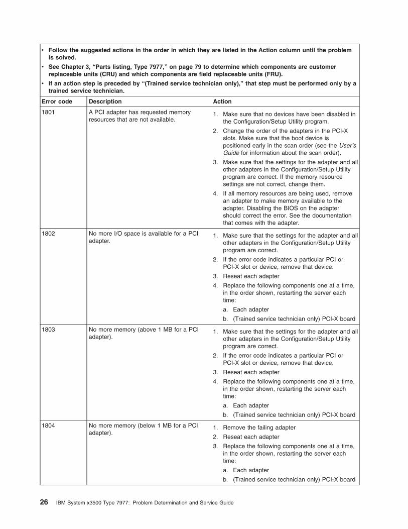
1801 A PCI adapter has requested memory
resources that are not available.
1. Make sure that no devices have been disabled in
the Configuration/Setup Utility program.
2. Change the order of the adapters in the PCI-X
slots. Make sure that the boot device is
positioned early in the scan order (see the User’s
Guide for information about the scan order).
3. Make sure that the settings for the adapter and all
other adapters in the Configuration/Setup Utility
program are correct. If the memory resource
settings are not correct, change them.
4. If all memory resources are being used, remove
an adapter to make memory available to the
adapter. Disabling the BIOS on the adapter
should correct the error. See the documentation
that comes with the adapter.
1802 No more I/O space is available for a PCI
adapter.
1. Make sure that the settings for the adapter and all
other adapters in the Configuration/Setup Utility
program are correct.
2. If the error code indicates a particular PCI or
PCI-X slot or device, remove that device.
3. Reseat each adapter
4. Replace the following components one at a time,
in the order shown, restarting the server each
time:
a. Each adapter
b. (Trained service technician only) PCI-X board
1803 No more memory (above 1 MB for a PCI
adapter).
1. Make sure that the settings for the adapter and all
other adapters in the Configuration/Setup Utility
program are correct.
2. If the error code indicates a particular PCI or
PCI-X slot or device, remove that device.
3. Reseat each adapter
4. Replace the following components one at a time,
in the order shown, restarting the server each
time:
a. Each adapter
b. (Trained service technician only) PCI-X board
1804 No more memory (below 1 MB for a PCI
adapter).
1. Remove the failing adapter
2. Reseat each adapter
3. Replace the following components one at a time,
in the order shown, restarting the server each
time:
a. Each adapter
b. (Trained service technician only) PCI-X board
26 IBM System x3500 Type 7977: Problem Determination and Service Guide
v Follow the suggested actions in the order in which they are listed in the Action column until the problem
is solved.
v See Chapter 3, “Parts listing, Type 7977,” on page 79 to determine which components are customer
replaceable units (CRU) and which components are field replaceable units (FRU).
v If an action step is preceded by “(Trained service technician only),” that step must be performed only by a
trained service technician.
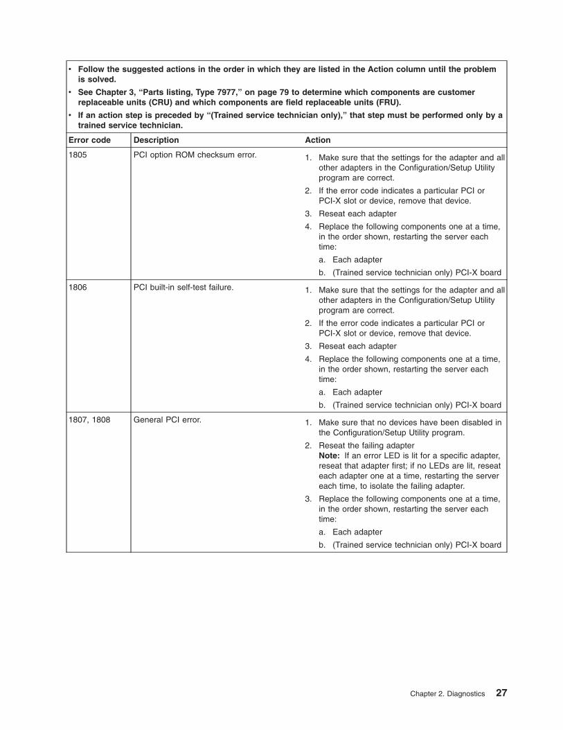
Error code Description Action
1805 PCI option ROM checksum error. 1. Make sure that the settings for the adapter and all
other adapters in the Configuration/Setup Utility
program are correct.
2. If the error code indicates a particular PCI or
PCI-X slot or device, remove that device.
3. Reseat each adapter
4. Replace the following components one at a time,
in the order shown, restarting the server each
time:
a. Each adapter
b. (Trained service technician only) PCI-X board
1806 PCI built-in self-test failure. 1. Make sure that the settings for the adapter and all
other adapters in the Configuration/Setup Utility
program are correct.
2. If the error code indicates a particular PCI or
PCI-X slot or device, remove that device.
3. Reseat each adapter
4. Replace the following components one at a time,
in the order shown, restarting the server each
time:
a. Each adapter
b. (Trained service technician only) PCI-X board
1807, 1808 General PCI error. 1. Make sure that no devices have been disabled in
the Configuration/Setup Utility program.
2. Reseat the failing adapter
Note: If an error LED is lit for a specific adapter,
reseat that adapter first; if no LEDs are lit, reseat
each adapter one at a time, restarting the server
each time, to isolate the failing adapter.
3. Replace the following components one at a time,
in the order shown, restarting the server each
time:
a. Each adapter
b. (Trained service technician only) PCI-X board
Chapter 2. Diagnostics 27
v Follow the suggested actions in the order in which they are listed in the Action column until the problem
is solved.
v See Chapter 3, “Parts listing, Type 7977,” on page 79 to determine which components are customer
replaceable units (CRU) and which components are field replaceable units (FRU).
v If an action step is preceded by “(Trained service technician only),” that step must be performed only by a
trained service technician.
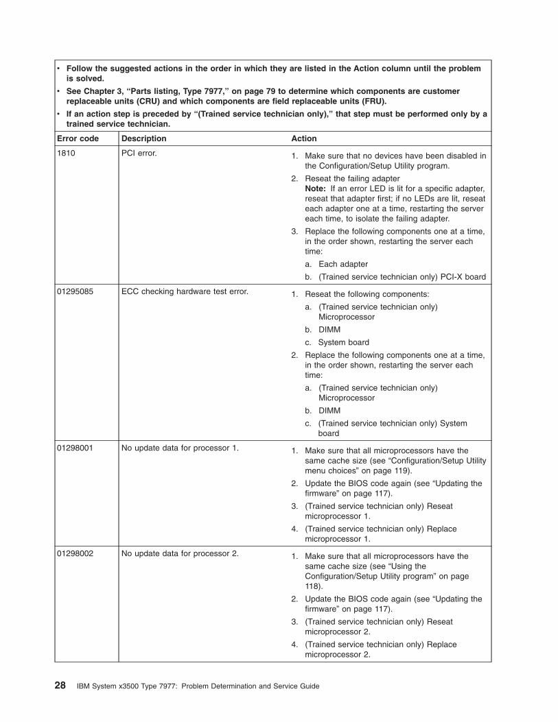
Error code Description Action
1810 PCI error. 1. Make sure that no devices have been disabled in
the Configuration/Setup Utility program.
2. Reseat the failing adapter
Note: If an error LED is lit for a specific adapter,
reseat that adapter first; if no LEDs are lit, reseat
each adapter one at a time, restarting the server
each time, to isolate the failing adapter.
3. Replace the following components one at a time,
in the order shown, restarting the server each
time:
a. Each adapter
b. (Trained service technician only) PCI-X board
01295085 ECC checking hardware test error. 1. Reseat the following components:
a. (Trained service technician only)
Microprocessor
b. DIMM
c. System board
2. Replace the following components one at a time,
in the order shown, restarting the server each
time:
a. (Trained service technician only)
Microprocessor
b. DIMM
c. (Trained service technician only) System
board
01298001 No update data for processor 1. 1. Make sure that all microprocessors have the
same cache size (see “Configuration/Setup Utility
menu choices” on page 119).
2. Update the BIOS code again (see “Updating the
firmware” on page 117).
3. (Trained service technician only) Reseat
microprocessor 1.
4. (Trained service technician only) Replace
microprocessor 1.
01298002 No update data for processor 2. 1. Make sure that all microprocessors have the
same cache size (see “Using the
Configuration/Setup Utility program” on page
118).
2. Update the BIOS code again (see “Updating the
firmware” on page 117).
3. (Trained service technician only) Reseat
microprocessor 2.
4. (Trained service technician only) Replace
microprocessor 2.
28 IBM System x3500 Type 7977: Problem Determination and Service Guide
v Follow the suggested actions in the order in which they are listed in the Action column until the problem
is solved.
v See Chapter 3, “Parts listing, Type 7977,” on page 79 to determine which components are customer
replaceable units (CRU) and which components are field replaceable units (FRU).
v If an action step is preceded by “(Trained service technician only),” that step must be performed only by a
trained service technician.
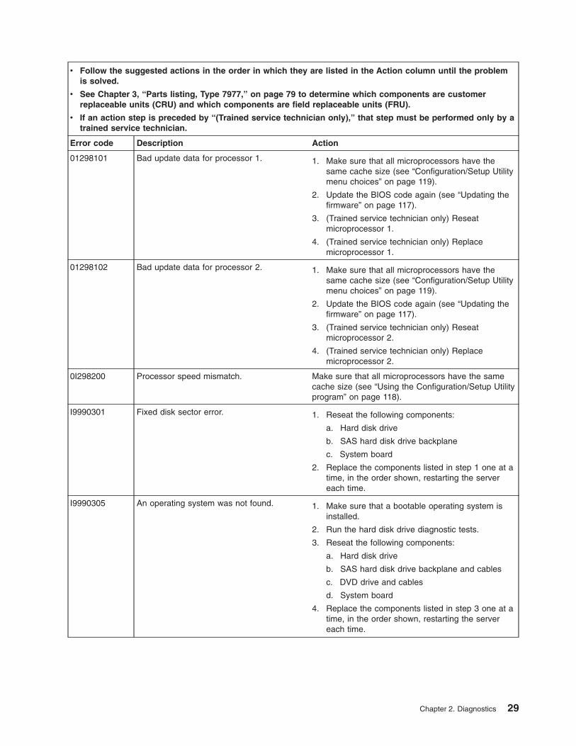
Error code Description Action
01298101 Bad update data for processor 1. 1. Make sure that all microprocessors have the
same cache size (see “Configuration/Setup Utility
menu choices” on page 119).
2. Update the BIOS code again (see “Updating the
firmware” on page 117).
3. (Trained service technician only) Reseat
microprocessor 1.
4. (Trained service technician only) Replace
microprocessor 1.
01298102 Bad update data for processor 2. 1. Make sure that all microprocessors have the
same cache size (see “Configuration/Setup Utility
menu choices” on page 119).
2. Update the BIOS code again (see “Updating the
firmware” on page 117).
3. (Trained service technician only) Reseat
microprocessor 2.
4. (Trained service technician only) Replace
microprocessor 2.
0I298200 Processor speed mismatch. Make sure that all microprocessors have the same
cache size (see “Using the Configuration/Setup Utility
program” on page 118).
I9990301 Fixed disk sector error. 1. Reseat the following components:
a. Hard disk drive
b. SAS hard disk drive backplane
c. System board
2. Replace the components listed in step 1 one at a
time, in the order shown, restarting the server
each time.
I9990305 An operating system was not found. 1. Make sure that a bootable operating system is
installed.
2. Run the hard disk drive diagnostic tests.
3. Reseat the following components:
a. Hard disk drive
b. SAS hard disk drive backplane and cables
c. DVD drive and cables
d. System board
4. Replace the components listed in step 3 one at a
time, in the order shown, restarting the server
each time.
Chapter 2. Diagnostics 29
v Follow the suggested actions in the order in which they are listed in the Action column until the problem
is solved.
v See Chapter 3, “Parts listing, Type 7977,” on page 79 to determine which components are customer
replaceable units (CRU) and which components are field replaceable units (FRU).
v If an action step is preceded by “(Trained service technician only),” that step must be performed only by a
trained service technician.
Error code Description Action
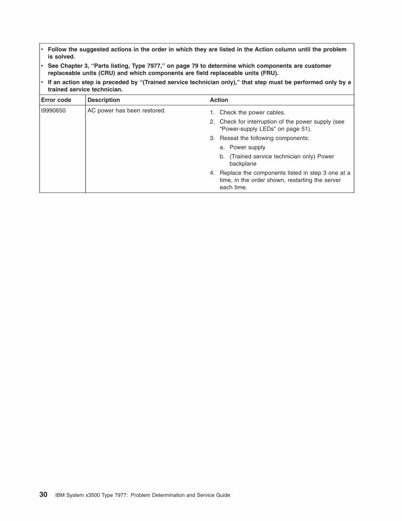
I9990650 AC power has been restored. 1. Check the power cables.
2. Check for interruption of the power supply (see
“Power-supply LEDs” on page 51).
3. Reseat the following components:
a. Power supply
b. (Trained service technician only) Power
backplane
4. Replace the components listed in step 3 one at a
time, in the order shown, restarting the server
each time.
30 IBM System x3500 Type 7977: Problem Determination and Service Guide
Checkout procedure
The checkout procedure is the sequence of tasks that you should follow to
diagnose a problem in the server.
About the checkout procedure
Before performing the checkout procedure for diagnosing hardware problems,
review the following information:
v Read the safety information that begins on page vii.
v The diagnostic programs provide the primary methods of testing the major
components of the server, such as the System board, Ethernet controller,
keyboard, mouse (pointing device), serial ports, and hard disk drives. You can
also use them to test some external devices. If you are not sure whether a
problem is caused by the hardware or by the software, you can use the
diagnostic programs to confirm that the hardware is working correctly.
v When you run the diagnostic programs, a single problem might cause more than
one error message. When this happens, correct the cause of the first error
message. The other error messages usually will not occur the next time you run
the diagnostic programs.
Exception: If there are multiple error codes or light path diagnostics LEDs that
indicate a microprocessor error, the error might be in a microprocessor or in a
microprocessor socket. See “Microprocessor problems” on page 38 for
information about diagnosing microprocessor problems.
v Before running the diagnostic programs, you must determine whether the failing
server is part of a shared hard disk drive cluster (two or more servers sharing
external storage devices). If it is part of a cluster, you can run all diagnostic
programs except the ones that test the storage unit (that is, a hard disk drive in
the storage unit) or the storage adapter that is attached to the storage unit. The
failing server might be part of a cluster if any of the following conditions is true:
– You have identified the failing server as part of a cluster (two or more servers
sharing external storage devices).
– One or more external storage units are attached to the failing server and at
least one of the attached storage units is also attached to another server or
unidentifiable device.
– One or more servers are located near the failing server.
Important: If the server is part of a shared hard disk drive cluster, run one test
at a time. Do not run any suite of tests, such as “quick” or “normal” tests,
because this might enable the hard disk drive diagnostic tests.
v If the server is halted and a POST error code is displayed, see “Error logs” on
page 18. If the server is halted and no error message is displayed, see
“Troubleshooting tables” on page 32 and “Solving undetermined problems” on
page 76.
v For information about power-supply problems, see “Solving power problems” on
page 75 and “Power-supply LEDs” on page 51.
v For intermittent problems, check the error log; see “Error logs” on page 18 and
“Diagnostic programs, messages, and error codes” on page 52.
Performing the checkout procedure
To perform the checkout procedure, complete the following steps:
1. Is the server part of a cluster?
Chapter 2. Diagnostics 31
v No: Go to step 2.
v Yes: Shut down all failing servers that are related to the cluster. Go to step 2.
2. Complete the following steps:
a. Turn off the server and all external devices.
b. Check all cables and power cords.
c. Set all display controls to the middle positions.
d. Turn on all external devices.
e. Turn on the server. If the server does not start, see “Troubleshooting tables”.
f. Check the system-error LED on the operator information panel. If it is
flashing, check the light path diagnostics LEDs (see “Light path diagnostics”
on page 45).
g. Check for the following results:
v Successful completion of POST, indicated by a single beep
v Successful completion of startup, indicated by a readable display of the
operating-system desktop
3. Did a single beep sound and are there readable instructions on the main menu?
v No: Find the failure symptom in “Troubleshooting tables”; if necessary, see
“Solving undetermined problems” on page 76.
v Yes: Run the diagnostic programs (see “Running the diagnostic programs” on
page 52).
– If you receive an error, see “Diagnostic error codes” on page 54.
– If the diagnostic programs were completed successfully and you still
suspect a problem, see “Solving undetermined problems” on page 76.
Important: If the server has a baseboard management controller, clear the BMC
log and system-event log after you resolve the condition. This will turn off the
information LED.
Checkpoint codes (trained service technicians only)
A checkpoint code identifies the check that was occurring when the server stopped;
it does not provide error codes or suggest replacement components. Checkpoint
codes are shown on the checkpoint display. By using the checkpoint display, you do
not have to wait for the video to initialize each time you restart the server.
Only one type of checkpoint code is supported in your server: BIOS checkpoint
codes. The BIOS checkpoint codes might change when the BIOS code is updated.
To read the BIOS checkpoint codes you will need to install a PCI POST card in one
of the PCI slots.
For a list of checkpoint codes for the IBM System x3500 server, see
http://www.ibm.com/pc/qtechinfo/MIGR-4ZKPPT.html.
Troubleshooting tables
Use the troubleshooting tables to find solutions to problems that have identifiable
symptoms.
If you cannot find the problem in these tables, see “Running the diagnostic
programs” on page 52 for information about testing the server.
32 IBM System x3500 Type 7977: Problem Determination and Service Guide
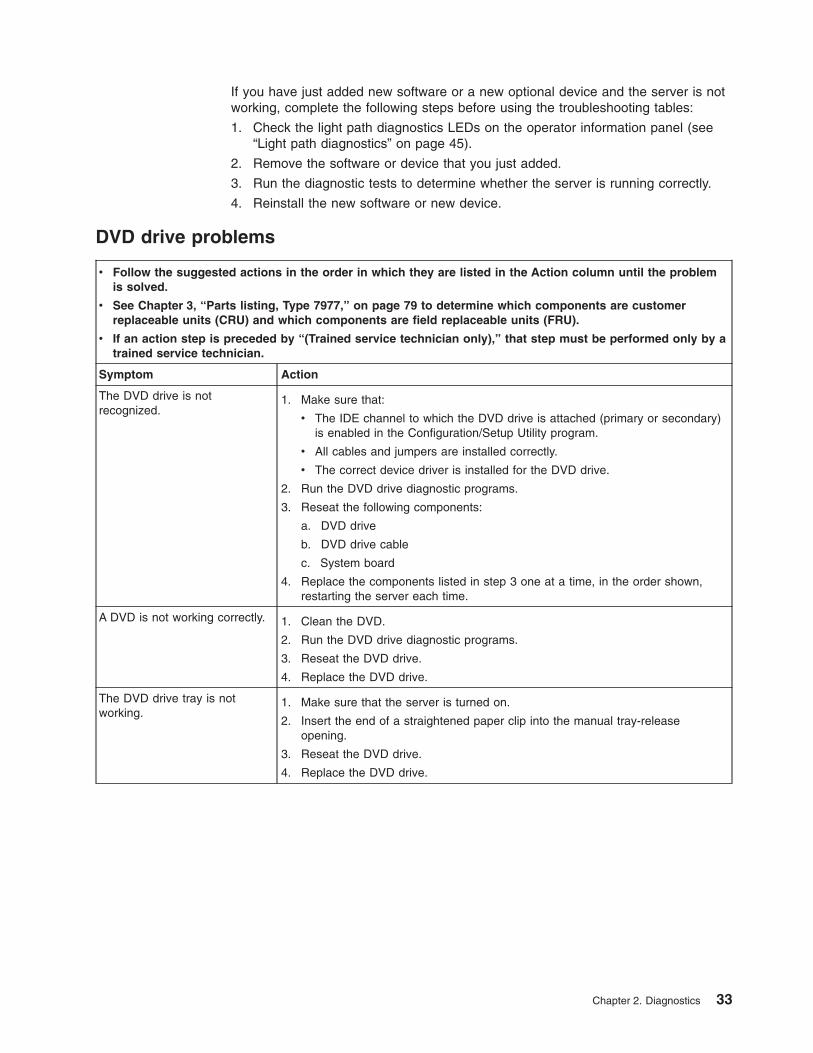
If you have just added new software or a new optional device and the server is not
working, complete the following steps before using the troubleshooting tables:
1. Check the light path diagnostics LEDs on the operator information panel (see
“Light path diagnostics” on page 45).
2. Remove the software or device that you just added.
3. Run the diagnostic tests to determine whether the server is running correctly.
4. Reinstall the new software or new device.
DVD drive problems
v Follow the suggested actions in the order in which they are listed in the Action column until the problem
is solved.
v See Chapter 3, “Parts listing, Type 7977,” on page 79 to determine which components are customer
replaceable units (CRU) and which components are field replaceable units (FRU).
v If an action step is preceded by “(Trained service technician only),” that step must be performed only by a
trained service technician.
Symptom Action
The DVD drive is not
recognized.
1. Make sure that:
v The IDE channel to which the DVD drive is attached (primary or secondary)
is enabled in the Configuration/Setup Utility program.
v All cables and jumpers are installed correctly.
v The correct device driver is installed for the DVD drive.
2. Run the DVD drive diagnostic programs.
3. Reseat the following components:
a. DVD drive
b. DVD drive cable
c. System board
4. Replace the components listed in step 3 one at a time, in the order shown,
restarting the server each time.
A DVD is not working correctly. 1. Clean the DVD.
2. Run the DVD drive diagnostic programs.
3. Reseat the DVD drive.
4. Replace the DVD drive.
The DVD drive tray is not
working.
1. Make sure that the server is turned on.
2. Insert the end of a straightened paper clip into the manual tray-release
opening.
3. Reseat the DVD drive.
4. Replace the DVD drive.
Chapter 2. Diagnostics 33
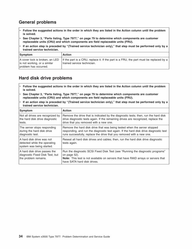
General problems
v Follow the suggested actions in the order in which they are listed in the Action column until the problem
is solved.
v See Chapter 3, “Parts listing, Type 7977,” on page 79 to determine which components are customer
replaceable units (CRU) and which components are field replaceable units (FRU).
v If an action step is preceded by “(Trained service technician only),” that step must be performed only by a
trained service technician.
Symptom Action
A cover lock is broken, an LED
is not working, or a similar
problem has occurred.
If the part is a CRU, replace it. If the part is a FRU, the part must be replaced by a
trained service technician.
Hard disk drive problems
v Follow the suggested actions in the order in which they are listed in the Action column until the problem
is solved.
v See Chapter 3, “Parts listing, Type 7977,” on page 79 to determine which components are customer
replaceable units (CRU) and which components are field replaceable units (FRU).
v If an action step is preceded by “(Trained service technician only),” that step must be performed only by a
trained service technician.
Symptom Action
Not all drives are recognized by
the hard disk drive diagnostic
tests.
Remove the drive that is indicated by the diagnostic tests; then, run the hard disk
drive diagnostic tests again. If the remaining drives are recognized, replace the
drive that you removed with a new one.
The server stops responding
during the hard disk drive
diagnostic test.
Remove the hard disk drive that was being tested when the server stopped
responding, and run the diagnostic test again. If the hard disk drive diagnostic test
runs successfully, replace the drive that you removed with a new one.
A hard disk drive was not
detected while the operating
system was being started.
Reseat all hard disk drives and cables; then, run the hard disk drive diagnostic
tests again.
A hard disk drive passes the
diagnostic Fixed Disk Test, but
the problem remains.
Run the diagnostic SCSI Fixed Disk Test (see “Running the diagnostic programs”
on page 52).
Note: This test is not available on servers that have RAID arrays or servers that
have SATA hard disk drives.
34 IBM System x3500 Type 7977: Problem Determination and Service Guide
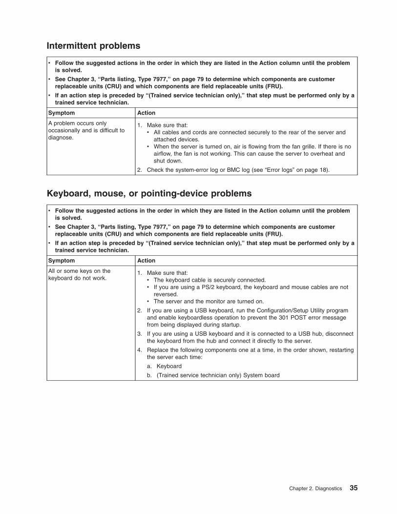
Intermittent problems
v Follow the suggested actions in the order in which they are listed in the Action column until the problem
is solved.
v See Chapter 3, “Parts listing, Type 7977,” on page 79 to determine which components are customer
replaceable units (CRU) and which components are field replaceable units (FRU).
v If an action step is preceded by “(Trained service technician only),” that step must be performed only by a
trained service technician.
Symptom Action
A problem occurs only
occasionally and is difficult to
diagnose.
1. Make sure that:
v All cables and cords are connected securely to the rear of the server and
attached devices.
v When the server is turned on, air is flowing from the fan grille. If there is no
airflow, the fan is not working. This can cause the server to overheat and
shut down.
2. Check the system-error log or BMC log (see “Error logs” on page 18).
Keyboard, mouse, or pointing-device problems
v Follow the suggested actions in the order in which they are listed in the Action column until the problem
is solved.
v See Chapter 3, “Parts listing, Type 7977,” on page 79 to determine which components are customer
replaceable units (CRU) and which components are field replaceable units (FRU).
v If an action step is preceded by “(Trained service technician only),” that step must be performed only by a
trained service technician.
Symptom Action
All or some keys on the
keyboard do not work.
1. Make sure that:
v The keyboard cable is securely connected.
v If you are using a PS/2 keyboard, the keyboard and mouse cables are not
reversed.
v The server and the monitor are turned on.
2. If you are using a USB keyboard, run the Configuration/Setup Utility program
and enable keyboardless operation to prevent the 301 POST error message
from being displayed during startup.
3. If you are using a USB keyboard and it is connected to a USB hub, disconnect
the keyboard from the hub and connect it directly to the server.
4. Replace the following components one at a time, in the order shown, restarting
the server each time:
a. Keyboard
b. (Trained service technician only) System board
Chapter 2. Diagnostics 35
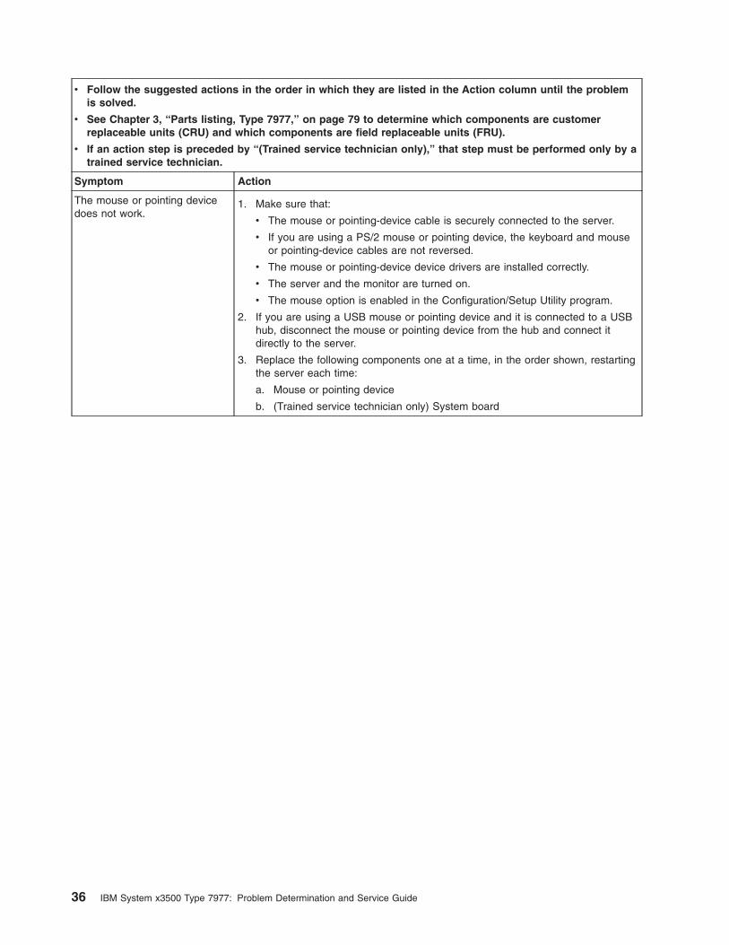
v Follow the suggested actions in the order in which they are listed in the Action column until the problem
is solved.
v See Chapter 3, “Parts listing, Type 7977,” on page 79 to determine which components are customer
replaceable units (CRU) and which components are field replaceable units (FRU).
v If an action step is preceded by “(Trained service technician only),” that step must be performed only by a
trained service technician.
Symptom Action
The mouse or pointing device
does not work.
1. Make sure that:
v The mouse or pointing-device cable is securely connected to the server.
v If you are using a PS/2 mouse or pointing device, the keyboard and mouse
or pointing-device cables are not reversed.
v The mouse or pointing-device device drivers are installed correctly.
v The server and the monitor are turned on.
v The mouse option is enabled in the Configuration/Setup Utility program.
2. If you are using a USB mouse or pointing device and it is connected to a USB
hub, disconnect the mouse or pointing device from the hub and connect it
directly to the server.
3. Replace the following components one at a time, in the order shown, restarting
the server each time:
a. Mouse or pointing device
b. (Trained service technician only) System board
36 IBM System x3500 Type 7977: Problem Determination and Service Guide
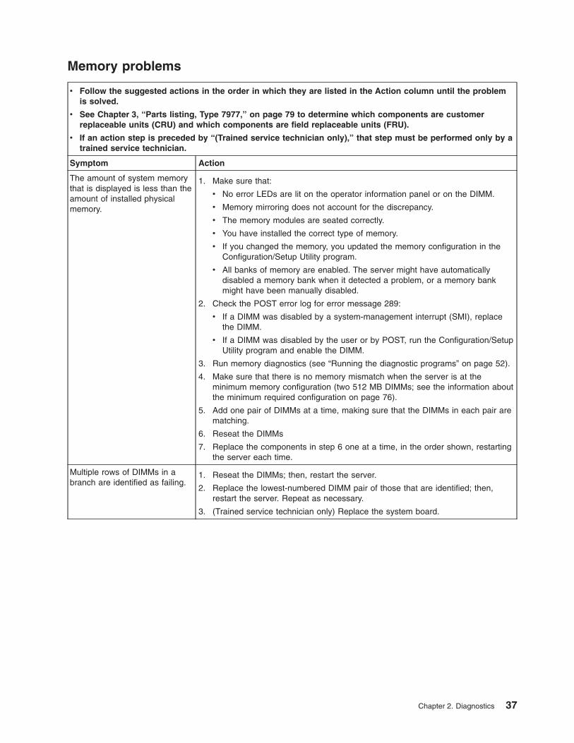
Memory problems
v Follow the suggested actions in the order in which they are listed in the Action column until the problem
is solved.
v See Chapter 3, “Parts listing, Type 7977,” on page 79 to determine which components are customer
replaceable units (CRU) and which components are field replaceable units (FRU).
v If an action step is preceded by “(Trained service technician only),” that step must be performed only by a
trained service technician.
Symptom Action
The amount of system memory
that is displayed is less than the
amount of installed physical
memory.
1. Make sure that:
v No error LEDs are lit on the operator information panel or on the DIMM.
v Memory mirroring does not account for the discrepancy.
v The memory modules are seated correctly.
v You have installed the correct type of memory.
v If you changed the memory, you updated the memory configuration in the
Configuration/Setup Utility program.
v All banks of memory are enabled. The server might have automatically
disabled a memory bank when it detected a problem, or a memory bank
might have been manually disabled.
2. Check the POST error log for error message 289:
v If a DIMM was disabled by a system-management interrupt (SMI), replace
the DIMM.
v If a DIMM was disabled by the user or by POST, run the Configuration/Setup
Utility program and enable the DIMM.
3. Run memory diagnostics (see “Running the diagnostic programs” on page 52).
4. Make sure that there is no memory mismatch when the server is at the
minimum memory configuration (two 512 MB DIMMs; see the information about
the minimum required configuration on page 76).
5. Add one pair of DIMMs at a time, making sure that the DIMMs in each pair are
matching.
6. Reseat the DIMMs
7. Replace the components in step 6 one at a time, in the order shown, restarting
the server each time.
Multiple rows of DIMMs in a
branch are identified as failing.
1. Reseat the DIMMs; then, restart the server.
2. Replace the lowest-numbered DIMM pair of those that are identified; then,
restart the server. Repeat as necessary.
3. (Trained service technician only) Replace the system board.
Chapter 2. Diagnostics 37
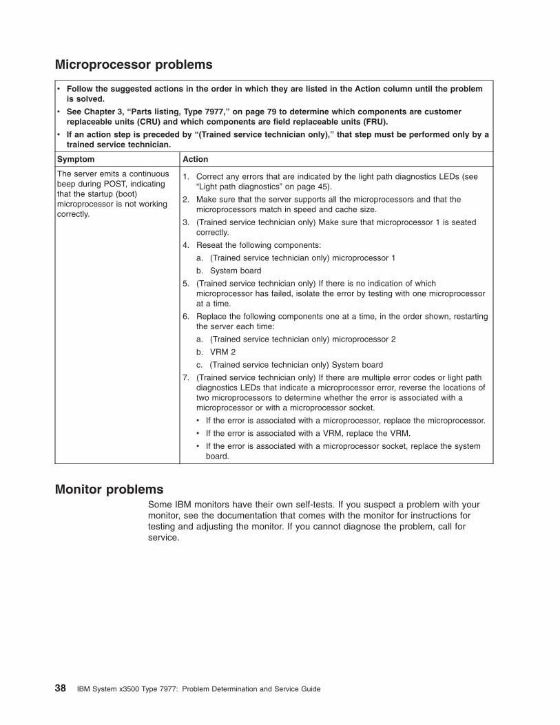
Microprocessor problems
v Follow the suggested actions in the order in which they are listed in the Action column until the problem
is solved.
v See Chapter 3, “Parts listing, Type 7977,” on page 79 to determine which components are customer
replaceable units (CRU) and which components are field replaceable units (FRU).
v If an action step is preceded by “(Trained service technician only),” that step must be performed only by a
trained service technician.
Symptom Action
The server emits a continuous
beep during POST, indicating
that the startup (boot)
microprocessor is not working
correctly.
1. Correct any errors that are indicated by the light path diagnostics LEDs (see
“Light path diagnostics” on page 45).
2. Make sure that the server supports all the microprocessors and that the
microprocessors match in speed and cache size.
3. (Trained service technician only) Make sure that microprocessor 1 is seated
correctly.
4. Reseat the following components:
a. (Trained service technician only) microprocessor 1
b. System board
5. (Trained service technician only) If there is no indication of which
microprocessor has failed, isolate the error by testing with one microprocessor
at a time.
6. Replace the following components one at a time, in the order shown, restarting
the server each time:
a. (Trained service technician only) microprocessor 2
b. VRM 2
c. (Trained service technician only) System board
7. (Trained service technician only) If there are multiple error codes or light path
diagnostics LEDs that indicate a microprocessor error, reverse the locations of
two microprocessors to determine whether the error is associated with a
microprocessor or with a microprocessor socket.
v If the error is associated with a microprocessor, replace the microprocessor.
v If the error is associated with a VRM, replace the VRM.
v If the error is associated with a microprocessor socket, replace the system
board.
Monitor problems
Some IBM monitors have their own self-tests. If you suspect a problem with your
monitor, see the documentation that comes with the monitor for instructions for
testing and adjusting the monitor. If you cannot diagnose the problem, call for
service.
38 IBM System x3500 Type 7977: Problem Determination and Service Guide
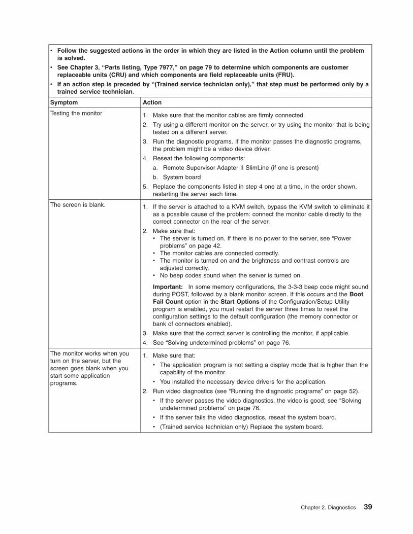
v Follow the suggested actions in the order in which they are listed in the Action column until the problem
is solved.
v See Chapter 3, “Parts listing, Type 7977,” on page 79 to determine which components are customer
replaceable units (CRU) and which components are field replaceable units (FRU).
v If an action step is preceded by “(Trained service technician only),” that step must be performed only by a
trained service technician.
Symptom Action
Testing the monitor 1. Make sure that the monitor cables are firmly connected.
2. Try using a different monitor on the server, or try using the monitor that is being
tested on a different server.
3. Run the diagnostic programs. If the monitor passes the diagnostic programs,
the problem might be a video device driver.
4. Reseat the following components:
a. Remote Supervisor Adapter II SlimLine (if one is present)
b. System board
5. Replace the components listed in step 4 one at a time, in the order shown,
restarting the server each time.
The screen is blank. 1. If the server is attached to a KVM switch, bypass the KVM switch to eliminate it
as a possible cause of the problem: connect the monitor cable directly to the
correct connector on the rear of the server.
2. Make sure that:
v The server is turned on. If there is no power to the server, see “Power
problems” on page 42.
v The monitor cables are connected correctly.
v The monitor is turned on and the brightness and contrast controls are
adjusted correctly.
v No beep codes sound when the server is turned on.
Important: In some memory configurations, the 3-3-3 beep code might sound
during POST, followed by a blank monitor screen. If this occurs and the Boot
Fail Count option in the Start Options of the Configuration/Setup Utility
program is enabled, you must restart the server three times to reset the
configuration settings to the default configuration (the memory connector or
bank of connectors enabled).
3. Make sure that the correct server is controlling the monitor, if applicable.
4. See “Solving undetermined problems” on page 76.
The monitor works when you
turn on the server, but the
screen goes blank when you
start some application
programs.
1. Make sure that:
v The application program is not setting a display mode that is higher than the
capability of the monitor.
v You installed the necessary device drivers for the application.
2. Run video diagnostics (see “Running the diagnostic programs” on page 52).
v If the server passes the video diagnostics, the video is good; see “Solving
undetermined problems” on page 76.
v If the server fails the video diagnostics, reseat the system board.
v (Trained service technician only) Replace the system board.
Chapter 2. Diagnostics 39
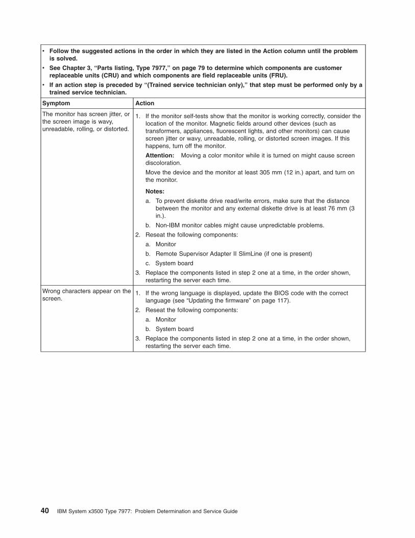
v Follow the suggested actions in the order in which they are listed in the Action column until the problem
is solved.
v See Chapter 3, “Parts listing, Type 7977,” on page 79 to determine which components are customer
replaceable units (CRU) and which components are field replaceable units (FRU).
v If an action step is preceded by “(Trained service technician only),” that step must be performed only by a
trained service technician.
Symptom Action
The monitor has screen jitter, or
the screen image is wavy,
unreadable, rolling, or distorted.
1. If the monitor self-tests show that the monitor is working correctly, consider the
location of the monitor. Magnetic fields around other devices (such as
transformers, appliances, fluorescent lights, and other monitors) can cause
screen jitter or wavy, unreadable, rolling, or distorted screen images. If this
happens, turn off the monitor.
Attention: Moving a color monitor while it is turned on might cause screen
discoloration.
Move the device and the monitor at least 305 mm (12 in.) apart, and turn on
the monitor.
Notes:
a. To prevent diskette drive read/write errors, make sure that the distance
between the monitor and any external diskette drive is at least 76 mm (3
in.).
b. Non-IBM monitor cables might cause unpredictable problems.
2. Reseat the following components:
a. Monitor
b. Remote Supervisor Adapter II SlimLine (if one is present)
c. System board
3. Replace the components listed in step 2 one at a time, in the order shown,
restarting the server each time.
Wrong characters appear on the
screen.
1. If the wrong language is displayed, update the BIOS code with the correct
language (see “Updating the firmware” on page 117).
2. Reseat the following components:
a. Monitor
b. System board
3. Replace the components listed in step 2 one at a time, in the order shown,
restarting the server each time.
40 IBM System x3500 Type 7977: Problem Determination and Service Guide
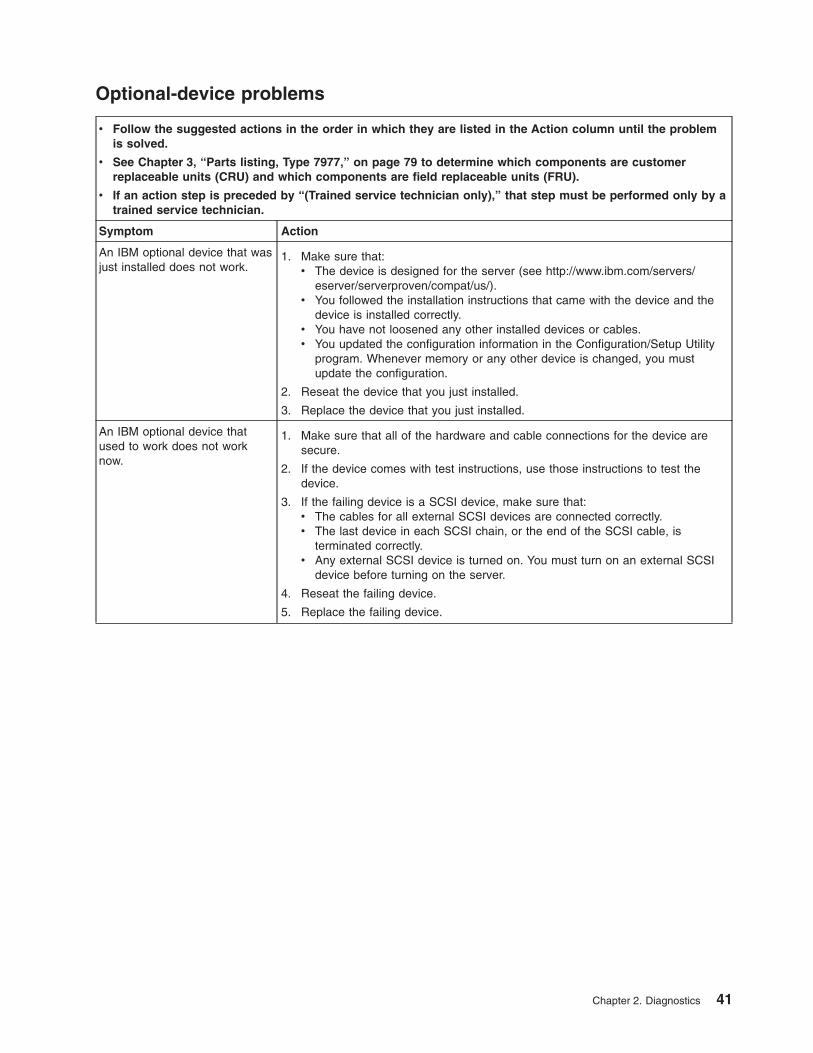
Optional-device problems
v Follow the suggested actions in the order in which they are listed in the Action column until the problem
is solved.
v See Chapter 3, “Parts listing, Type 7977,” on page 79 to determine which components are customer
replaceable units (CRU) and which components are field replaceable units (FRU).
v If an action step is preceded by “(Trained service technician only),” that step must be performed only by a
trained service technician.
Symptom Action
An IBM optional device that was
just installed does not work.
1. Make sure that:
v The device is designed for the server (see http://www.ibm.com/servers/eserver/serverproven/compat/us/).
v You followed the installation instructions that came with the device and the
device is installed correctly.
v You have not loosened any other installed devices or cables.
v You updated the configuration information in the Configuration/Setup Utility
program. Whenever memory or any other device is changed, you must
update the configuration.
2. Reseat the device that you just installed.
3. Replace the device that you just installed.
An IBM optional device that
used to work does not work
now.
1. Make sure that all of the hardware and cable connections for the device are
secure.
2. If the device comes with test instructions, use those instructions to test the
device.
3. If the failing device is a SCSI device, make sure that:
v The cables for all external SCSI devices are connected correctly.
v The last device in each SCSI chain, or the end of the SCSI cable, is
terminated correctly.
v Any external SCSI device is turned on. You must turn on an external SCSI
device before turning on the server.
4. Reseat the failing device.
5. Replace the failing device.
Chapter 2. Diagnostics 41
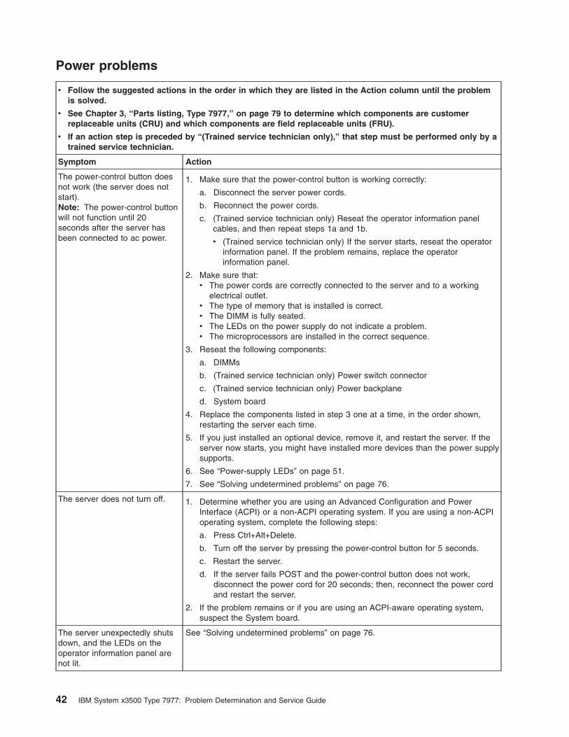
Power problems
v Follow the suggested actions in the order in which they are listed in the Action column until the problem
is solved.
v See Chapter 3, “Parts listing, Type 7977,” on page 79 to determine which components are customer
replaceable units (CRU) and which components are field replaceable units (FRU).
v If an action step is preceded by “(Trained service technician only),” that step must be performed only by a
trained service technician.
Symptom Action
The power-control button does
not work (the server does not
start).
Note: The power-control button
will not function until 20
seconds after the server has
been connected to ac power.
1. Make sure that the power-control button is working correctly:
a. Disconnect the server power cords.
b. Reconnect the power cords.
c. (Trained service technician only) Reseat the operator information panel
cables, and then repeat steps 1a and 1b.
v (Trained service technician only) If the server starts, reseat the operator
information panel. If the problem remains, replace the operator
information panel.
2. Make sure that:
v The power cords are correctly connected to the server and to a working
electrical outlet.
v The type of memory that is installed is correct.
v The DIMM is fully seated.
v The LEDs on the power supply do not indicate a problem.
v The microprocessors are installed in the correct sequence.
3. Reseat the following components:
a. DIMMs
b. (Trained service technician only) Power switch connector
c. (Trained service technician only) Power backplane
d. System board
4. Replace the components listed in step 3 one at a time, in the order shown,
restarting the server each time.
5. If you just installed an optional device, remove it, and restart the server. If the
server now starts, you might have installed more devices than the power supply
supports.
6. See “Power-supply LEDs” on page 51.
7. See “Solving undetermined problems” on page 76.
The server does not turn off. 1. Determine whether you are using an Advanced Configuration and Power
Interface (ACPI) or a non-ACPI operating system. If you are using a non-ACPI
operating system, complete the following steps:
a. Press Ctrl+Alt+Delete.
b. Turn off the server by pressing the power-control button for 5 seconds.
c. Restart the server.
d. If the server fails POST and the power-control button does not work,
disconnect the power cord for 20 seconds; then, reconnect the power cord
and restart the server.
2. If the problem remains or if you are using an ACPI-aware operating system,
suspect the System board.
The server unexpectedly shuts
down, and the LEDs on the
operator information panel are
not lit.
See “Solving undetermined problems” on page 76.
42 IBM System x3500 Type 7977: Problem Determination and Service Guide
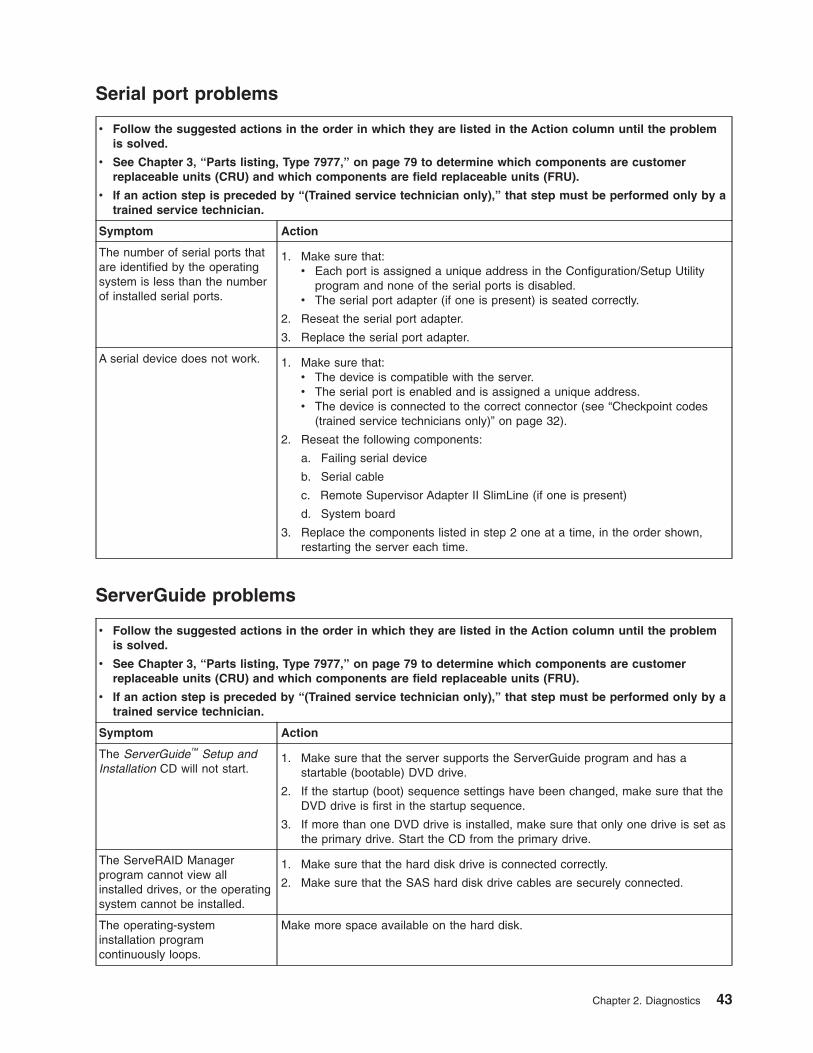
Serial port problems
v Follow the suggested actions in the order in which they are listed in the Action column until the problem
is solved.
v See Chapter 3, “Parts listing, Type 7977,” on page 79 to determine which components are customer
replaceable units (CRU) and which components are field replaceable units (FRU).
v If an action step is preceded by “(Trained service technician only),” that step must be performed only by a
trained service technician.
Symptom Action
The number of serial ports that
are identified by the operating
system is less than the number
of installed serial ports.
1. Make sure that:
v Each port is assigned a unique address in the Configuration/Setup Utility
program and none of the serial ports is disabled.
v The serial port adapter (if one is present) is seated correctly.
2. Reseat the serial port adapter.
3. Replace the serial port adapter.
A serial device does not work. 1. Make sure that:
v The device is compatible with the server.
v The serial port is enabled and is assigned a unique address.
v The device is connected to the correct connector (see “Checkpoint codes
(trained service technicians only)” on page 32).
2. Reseat the following components:
a. Failing serial device
b. Serial cable
c. Remote Supervisor Adapter II SlimLine (if one is present)
d. System board
3. Replace the components listed in step 2 one at a time, in the order shown,
restarting the server each time.
ServerGuide problems
v Follow the suggested actions in the order in which they are listed in the Action column until the problem
is solved.
v See Chapter 3, “Parts listing, Type 7977,” on page 79 to determine which components are customer
replaceable units (CRU) and which components are field replaceable units (FRU).
v If an action step is preceded by “(Trained service technician only),” that step must be performed only by a
trained service technician.
Symptom Action
The ServerGuide™ Setup and
Installation CD will not start.
1. Make sure that the server supports the ServerGuide program and has a
startable (bootable) DVD drive.
2. If the startup (boot) sequence settings have been changed, make sure that the
DVD drive is first in the startup sequence.
3. If more than one DVD drive is installed, make sure that only one drive is set as
the primary drive. Start the CD from the primary drive.
The ServeRAID Manager
program cannot view all
installed drives, or the operating
system cannot be installed.
1. Make sure that the hard disk drive is connected correctly.
2. Make sure that the SAS hard disk drive cables are securely connected.
The operating-system
installation program
continuously loops.
Make more space available on the hard disk.
Chapter 2. Diagnostics 43
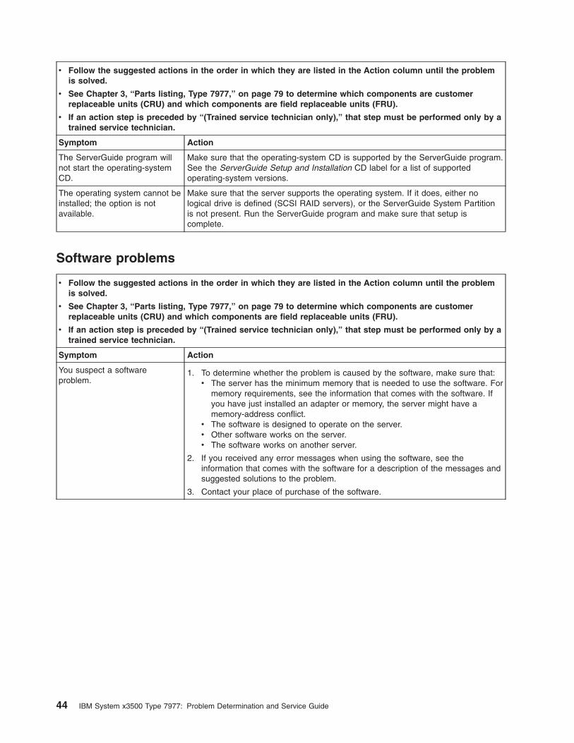
v Follow the suggested actions in the order in which they are listed in the Action column until the problem
is solved.
v See Chapter 3, “Parts listing, Type 7977,” on page 79 to determine which components are customer
replaceable units (CRU) and which components are field replaceable units (FRU).
v If an action step is preceded by “(Trained service technician only),” that step must be performed only by a
trained service technician.
Symptom Action
The ServerGuide program will
not start the operating-system
CD.
Make sure that the operating-system CD is supported by the ServerGuide program.
See the ServerGuide Setup and Installation CD label for a list of supported
operating-system versions.
The operating system cannot be
installed; the option is not
available.
Make sure that the server supports the operating system. If it does, either no
logical drive is defined (SCSI RAID servers), or the ServerGuide System Partition
is not present. Run the ServerGuide program and make sure that setup is
complete.
Software problems
v Follow the suggested actions in the order in which they are listed in the Action column until the problem
is solved.
v See Chapter 3, “Parts listing, Type 7977,” on page 79 to determine which components are customer
replaceable units (CRU) and which components are field replaceable units (FRU).
v If an action step is preceded by “(Trained service technician only),” that step must be performed only by a
trained service technician.
Symptom Action
You suspect a software
problem.
1. To determine whether the problem is caused by the software, make sure that:
v The server has the minimum memory that is needed to use the software. For
memory requirements, see the information that comes with the software. If
you have just installed an adapter or memory, the server might have a
memory-address conflict.
v The software is designed to operate on the server.
v Other software works on the server.
v The software works on another server.
2. If you received any error messages when using the software, see the
information that comes with the software for a description of the messages and
suggested solutions to the problem.
3. Contact your place of purchase of the software.
44 IBM System x3500 Type 7977: Problem Determination and Service Guide
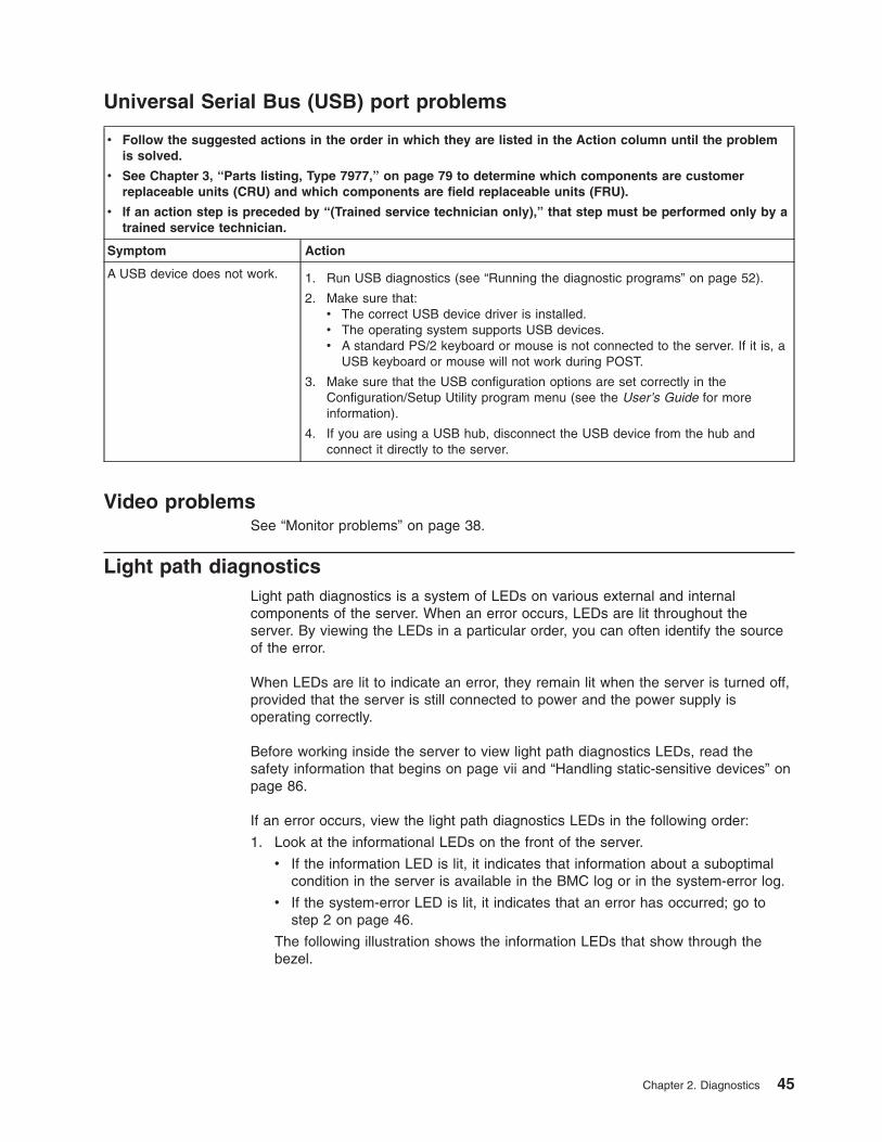
Universal Serial Bus (USB) port problems
v Follow the suggested actions in the order in which they are listed in the Action column until the problem
is solved.
v See Chapter 3, “Parts listing, Type 7977,” on page 79 to determine which components are customer
replaceable units (CRU) and which components are field replaceable units (FRU).
v If an action step is preceded by “(Trained service technician only),” that step must be performed only by a
trained service technician.
Symptom Action
A USB device does not work. 1. Run USB diagnostics (see “Running the diagnostic programs” on page 52).
2. Make sure that:
v The correct USB device driver is installed.
v The operating system supports USB devices.
v A standard PS/2 keyboard or mouse is not connected to the server. If it is, a
USB keyboard or mouse will not work during POST.
3. Make sure that the USB configuration options are set correctly in the
Configuration/Setup Utility program menu (see the User’s Guide for more
information).
4. If you are using a USB hub, disconnect the USB device from the hub and
connect it directly to the server.
Video problems
See “Monitor problems” on page 38.
Light path diagnostics
Light path diagnostics is a system of LEDs on various external and internal
components of the server. When an error occurs, LEDs are lit throughout the
server. By viewing the LEDs in a particular order, you can often identify the source
of the error.
When LEDs are lit to indicate an error, they remain lit when the server is turned off,
provided that the server is still connected to power and the power supply is
operating correctly.
Before working inside the server to view light path diagnostics LEDs, read the
safety information that begins on page vii and “Handling static-sensitive devices” on
page 86.
If an error occurs, view the light path diagnostics LEDs in the following order:
1. Look at the informational LEDs on the front of the server.
v If the information LED is lit, it indicates that information about a suboptimal
condition in the server is available in the BMC log or in the system-error log.
v If the system-error LED is lit, it indicates that an error has occurred; go to
step 2 on page 46.
The following illustration shows the information LEDs that show through the
bezel.
Chapter 2. Diagnostics 45
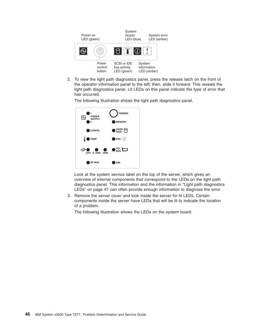
Powercontrolbutton
SystemlocatorLED (blue)
SysteminformationLED (amber)
System errorLED (amber)
SCSI or IDEbus activityLED (green)
Power-onLED (green)
2. To view the light path diagnostics panel, press the release latch on the front of
the operator information panel to the left; then, slide it forward. This reveals the
light path diagnostics panel. Lit LEDs on this panel indicate the type of error that
has occurred.
The following illustration shows the light path diagnostics panel.
CPU VRMS_ERR
MEMORY
DASD/RAID
NMISP BUS
FAN
POWERSUPPLY
PCIBUS
2
1
CONFIG
TEMP
REMIND
SEE INSIDE COVER FOR MORE SERVICE INFORMATION
Look at the system service label on the top of the server, which gives an
overview of internal components that correspond to the LEDs on the light path
diagnostics panel. This information and the information in “Light path diagnostics
LEDs” on page 47 can often provide enough information to diagnose the error.
3. Remove the server cover and look inside the server for lit LEDs. Certain
components inside the server have LEDs that will be lit to indicate the location
of a problem.
The following illustration shows the LEDs on the system board.
46 IBM System x3500 Type 7977: Problem Determination and Service Guide
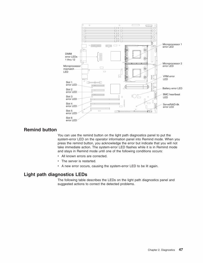
Slot 1error LED
Slot 2error LED
Slot 3error LED
Slot 4error LED
Slot 5error LED
Slot 6error LED
MicroprocessormismatchLED
DIMMerror LEDs1 thru 12
Microprocessor 1error LED
Microprocessor 2error LED
VRM errorLED
BMC heartbeatLED
ServeRAID-8kerror LED
Battery error LED
Remind button
You can use the remind button on the light path diagnostics panel to put the
system-error LED on the operator information panel into Remind mode. When you
press the remind button, you acknowledge the error but indicate that you will not
take immediate action. The system-error LED flashes while it is in Remind mode
and stays in Remind mode until one of the following conditions occurs:
v All known errors are corrected.
v The server is restarted.
v A new error occurs, causing the system-error LED to be lit again.
Light path diagnostics LEDs
The following table describes the LEDs on the light path diagnostics panel and
suggested actions to correct the detected problems.
Chapter 2. Diagnostics 47
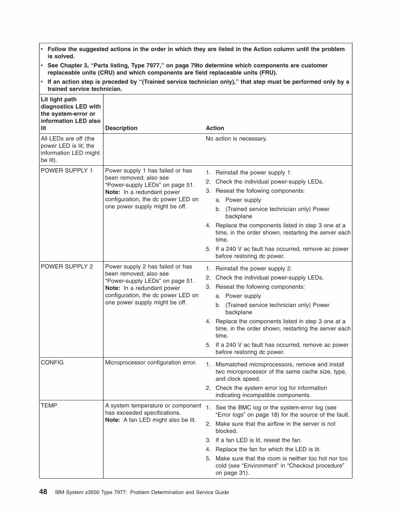
v Follow the suggested actions in the order in which they are listed in the Action column until the problem
is solved.
v See Chapter 3, “Parts listing, Type 7977,” on page 79to determine which components are customer
replaceable units (CRU) and which components are field replaceable units (FRU).
v If an action step is preceded by “(Trained service technician only),” that step must be performed only by a
trained service technician.
Lit light path
diagnostics LED with
the system-error or
information LED also
lit Description Action
All LEDs are off (the
power LED is lit; the
information LED might
be lit).
No action is necessary.
POWER SUPPLY 1 Power supply 1 has failed or has
been removed; also see
“Power-supply LEDs” on page 51.
Note: In a redundant power
configuration, the dc power LED on
one power supply might be off.
1. Reinstall the power supply 1.
2. Check the individual power-supply LEDs.
3. Reseat the following components:
a. Power supply
b. (Trained service technician only) Power
backplane
4. Replace the components listed in step 3 one at a
time, in the order shown, restarting the server each
time.
5. If a 240 V ac fault has occurred, remove ac power
before restoring dc power.
POWER SUPPLY 2 Power supply 2 has failed or has
been removed; also see
“Power-supply LEDs” on page 51.
Note: In a redundant power
configuration, the dc power LED on
one power supply might be off.
1. Reinstall the power supply 2.
2. Check the individual power-supply LEDs.
3. Reseat the following components:
a. Power supply
b. (Trained service technician only) Power
backplane
4. Replace the components listed in step 3 one at a
time, in the order shown, restarting the server each
time.
5. If a 240 V ac fault has occurred, remove ac power
before restoring dc power.
CONFIG Microprocessor configuration error. 1. Mismatched microprocessors, remove and install
two microprocessor of the same cache size, type,
and clock speed.
2. Check the system error log for information
indicating incompatible components.
TEMP A system temperature or component
has exceeded specifications.
Note: A fan LED might also be lit.
1. See the BMC log or the system-error log (see
“Error logs” on page 18) for the source of the fault.
2. Make sure that the airflow in the server is not
blocked.
3. If a fan LED is lit, reseat the fan.
4. Replace the fan for which the LED is lit.
5. Make sure that the room is neither too hot nor too
cold (see “Environment” in “Checkout procedure”
on page 31).
48 IBM System x3500 Type 7977: Problem Determination and Service Guide
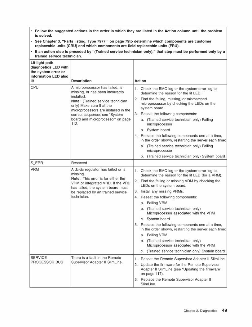
v Follow the suggested actions in the order in which they are listed in the Action column until the problem
is solved.
v See Chapter 3, “Parts listing, Type 7977,” on page 79to determine which components are customer
replaceable units (CRU) and which components are field replaceable units (FRU).
v If an action step is preceded by “(Trained service technician only),” that step must be performed only by a
trained service technician.
Lit light path
diagnostics LED with
the system-error or
information LED also
lit Description Action
CPU A microprocessor has failed, is
missing, or has been incorrectly
installed.
Note: (Trained service technician
only) Make sure that the
microprocessors are installed in the
correct sequence; see “System
board and microprocessor” on page
112.
1. Check the BMC log or the system-error log to
determine the reason for the lit LED.
2. Find the failing, missing, or mismatched
microprocessor by checking the LEDs on the
system board.
3. Reseat the following components:
a. (Trained service technician only) Failing
microprocessor
b. System board
4. Replace the following components one at a time,
in the order shown, restarting the server each time:
a. (Trained service technician only) Failing
microprocessor
b. (Trained service technician only) System board
S_ERR Reserved
VRM A dc-dc regulator has failed or is
missing.
Note: This error is for either the
VRM or integrated VRD. If the VRD
has failed, the system board must
be replaced by an trained service
technician.
1. Check the BMC log or the system-error log to
determine the reason for the lit LED (for a VRM).
2. Find the failing or missing VRM by checking the
LEDs on the system board.
3. Install any missing VRMs.
4. Reseat the following components:
a. Failing VRM
b. (Trained service technician only)
Microprocessor associated with the VRM
c. System board
5. Replace the following components one at a time,
in the order shown, restarting the server each time:
a. Failing VRM
b. (Trained service technician only)
Microprocessor associated with the VRM
c. (Trained service technician only) System board
SERVICE
PROCESSOR BUS
There is a fault in the Remote
Supervisor Adapter II SlimLine.
1. Reseat the Remote Supervisor Adapter II SlimLine.
2. Update the firmware for the Remote Supervisor
Adapter II SlimLine (see “Updating the firmware”
on page 117).
3. Replace the Remote Supervisor Adapter II
SlimLine.
Chapter 2. Diagnostics 49
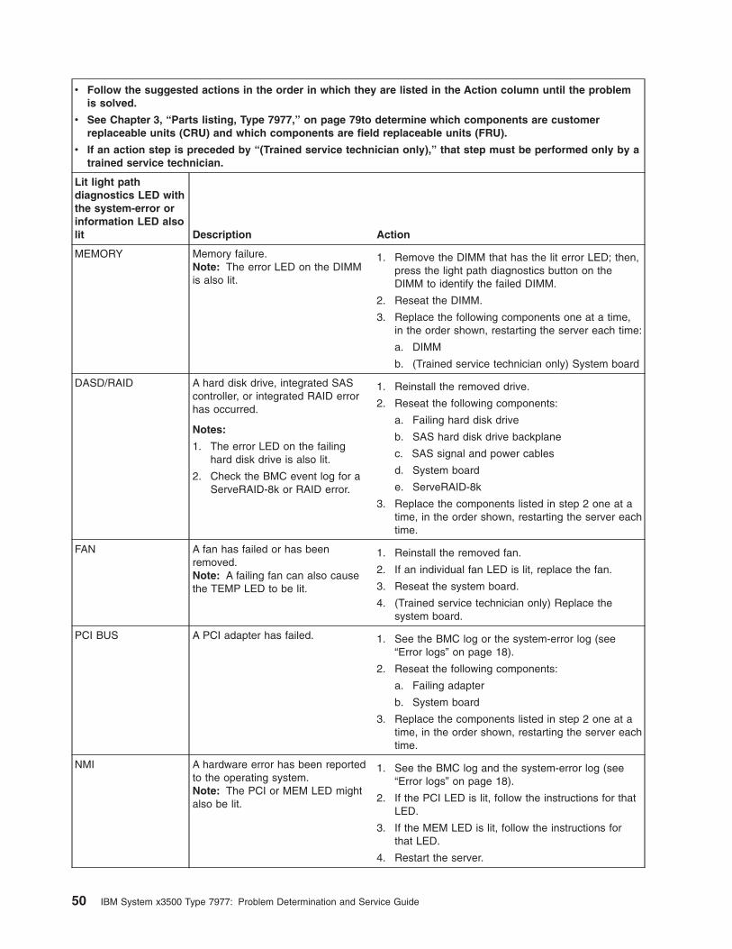
v Follow the suggested actions in the order in which they are listed in the Action column until the problem
is solved.
v See Chapter 3, “Parts listing, Type 7977,” on page 79to determine which components are customer
replaceable units (CRU) and which components are field replaceable units (FRU).
v If an action step is preceded by “(Trained service technician only),” that step must be performed only by a
trained service technician.
Lit light path
diagnostics LED with
the system-error or
information LED also
lit Description Action
MEMORY Memory failure.
Note: The error LED on the DIMM
is also lit.
1. Remove the DIMM that has the lit error LED; then,
press the light path diagnostics button on the
DIMM to identify the failed DIMM.
2. Reseat the DIMM.
3. Replace the following components one at a time,
in the order shown, restarting the server each time:
a. DIMM
b. (Trained service technician only) System board
DASD/RAID A hard disk drive, integrated SAS
controller, or integrated RAID error
has occurred.
Notes:
1. The error LED on the failing
hard disk drive is also lit.
2. Check the BMC event log for a
ServeRAID-8k or RAID error.
1. Reinstall the removed drive.
2. Reseat the following components:
a. Failing hard disk drive
b. SAS hard disk drive backplane
c. SAS signal and power cables
d. System board
e. ServeRAID-8k
3. Replace the components listed in step 2 one at a
time, in the order shown, restarting the server each
time.
FAN A fan has failed or has been
removed.
Note: A failing fan can also cause
the TEMP LED to be lit.
1. Reinstall the removed fan.
2. If an individual fan LED is lit, replace the fan.
3. Reseat the system board.
4. (Trained service technician only) Replace the
system board.
PCI BUS A PCI adapter has failed. 1. See the BMC log or the system-error log (see
“Error logs” on page 18).
2. Reseat the following components:
a. Failing adapter
b. System board
3. Replace the components listed in step 2 one at a
time, in the order shown, restarting the server each
time.
NMI A hardware error has been reported
to the operating system.
Note: The PCI or MEM LED might
also be lit.
1. See the BMC log and the system-error log (see
“Error logs” on page 18).
2. If the PCI LED is lit, follow the instructions for that
LED.
3. If the MEM LED is lit, follow the instructions for
that LED.
4. Restart the server.
50 IBM System x3500 Type 7977: Problem Determination and Service Guide
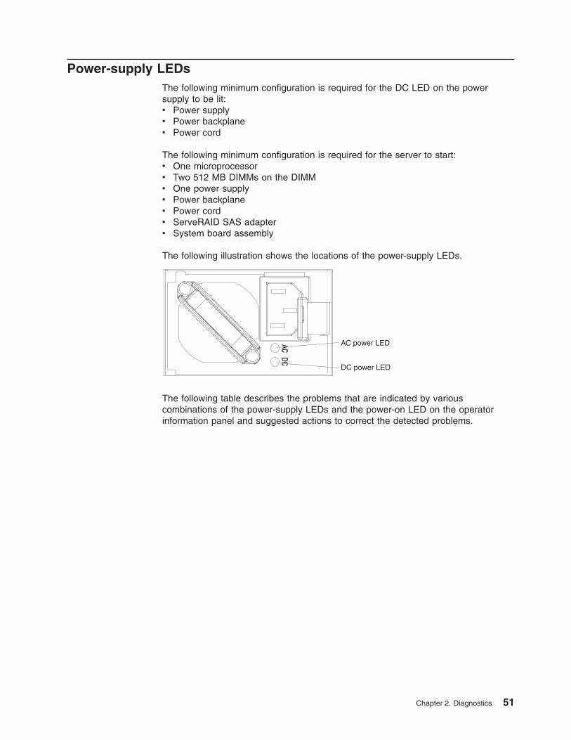
Power-supply LEDs
The following minimum configuration is required for the DC LED on the power
supply to be lit:
v Power supply
v Power backplane
v Power cord
The following minimum configuration is required for the server to start:
v One microprocessor
v Two 512 MB DIMMs on the DIMM
v One power supply
v Power backplane
v Power cord
v ServeRAID SAS adapter
v System board assembly
The following illustration shows the locations of the power-supply LEDs.
AC power LED
DC power LED
The following table describes the problems that are indicated by various
combinations of the power-supply LEDs and the power-on LED on the operator
information panel and suggested actions to correct the detected problems.
Chapter 2. Diagnostics 51
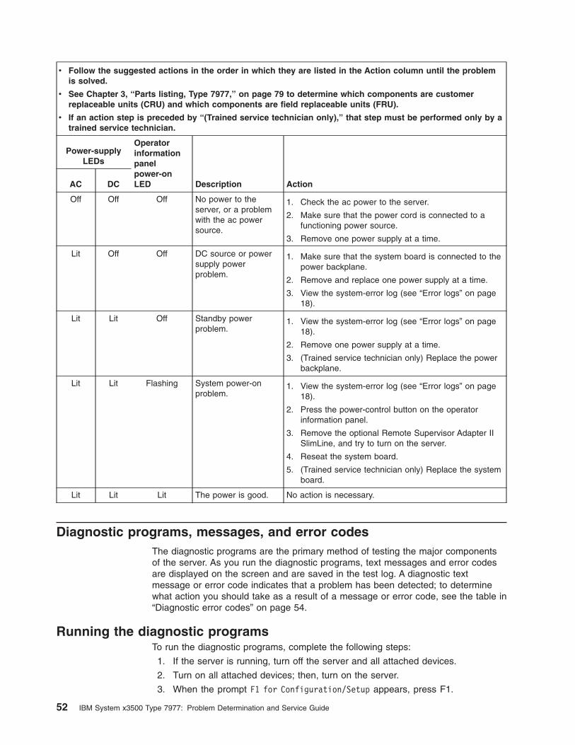
v Follow the suggested actions in the order in which they are listed in the Action column until the problem
is solved.
v See Chapter 3, “Parts listing, Type 7977,” on page 79 to determine which components are customer
replaceable units (CRU) and which components are field replaceable units (FRU).
v If an action step is preceded by “(Trained service technician only),” that step must be performed only by a
trained service technician.
Power-supply
LEDs
Operator
information
panel
power-on
LED Description Action AC DC
Off Off Off No power to the
server, or a problem
with the ac power
source.
1. Check the ac power to the server.
2. Make sure that the power cord is connected to a
functioning power source.
3. Remove one power supply at a time.
Lit Off Off DC source or power
supply power
problem.
1. Make sure that the system board is connected to the
power backplane.
2. Remove and replace one power supply at a time.
3. View the system-error log (see “Error logs” on page
18).
Lit Lit Off Standby power
problem.
1. View the system-error log (see “Error logs” on page
18).
2. Remove one power supply at a time.
3. (Trained service technician only) Replace the power
backplane.
Lit Lit Flashing System power-on
problem.
1. View the system-error log (see “Error logs” on page
18).
2. Press the power-control button on the operator
information panel.
3. Remove the optional Remote Supervisor Adapter II
SlimLine, and try to turn on the server.
4. Reseat the system board.
5. (Trained service technician only) Replace the system
board.
Lit Lit Lit The power is good. No action is necessary.
Diagnostic programs, messages, and error codes
The diagnostic programs are the primary method of testing the major components
of the server. As you run the diagnostic programs, text messages and error codes
are displayed on the screen and are saved in the test log. A diagnostic text
message or error code indicates that a problem has been detected; to determine
what action you should take as a result of a message or error code, see the table in
“Diagnostic error codes” on page 54.
Running the diagnostic programs
To run the diagnostic programs, complete the following steps:
1. If the server is running, turn off the server and all attached devices.
2. Turn on all attached devices; then, turn on the server.
3. When the prompt F1 for Configuration/Setup appears, press F1.
52 IBM System x3500 Type 7977: Problem Determination and Service Guide
4. When the Configuration/Setup Utility menu appears, select Start Options.
5. From the Start Options menu, select Startup Sequence Options.
6. Note the device that is selected as the first startup device. Later, you must
restore this setting.
7. Select DVD-ROM as the first startup device.
8. Press Esc two times to return to the Configuration/Setup Utility menu.
9. Insert the IBM Enhanced Diagnostics CD in the CD drive.
10. Select Save & Exit Setup and follow the prompts. The diagnostics will load.
11. From the diagnostic programs screen, select the test that you want to run, and
follow the instructions on the screen.
When you are diagnosing hard disk drives, select SCSI Attached Disk Test
for the most thorough test. Select Fixed Disk Test for any of the following
situations:
v You want to run a faster test.
v The server contains RAID arrays not connected to the integrated SAS
controller.
v The server contains SATA or IDE hard disk drives not connected to the
integrated SAS controller.
To determine what action you should take as a result of a diagnostic text message
or error code, see the table in “Diagnostic error codes” on page 54.
If the diagnostic programs do not detect any hardware errors but the problem
remains during normal server operations, a software error might be the cause. If
you suspect a software problem, see the information that comes with your software.
A single problem might cause more than one error message. When this happens,
correct the cause of the first error message. The other error messages usually will
not occur the next time you run the diagnostic programs.
Exception: If there are multiple error codes or light path diagnostics LEDs that
indicate a microprocessor error, the error might be in a microprocessor or in a
microprocessor socket. See “Microprocessor problems” on page 38 for information
about diagnosing microprocessor problems.
If the server stops during testing and you cannot continue, restart the server and try
running the diagnostic programs again. If the problem remains, replace the
component that was being tested when the server stopped.
The keyboard and mouse (pointing device) tests assume that a keyboard and
mouse are attached to the server. If no mouse is attached to the server, you cannot
use the Next Cat and Prev Cat buttons to select categories. All other
mouse-selectable functions are available through function keys. You can use the
regular keyboard test to test a USB keyboard, and you can use the regular mouse
test to test a USB mouse. You can run the USB interface test only if no USB
devices are attached. The USB test will not run if a Remote Supervisor Adapter II
SlimLine is installed.
To view server configuration information (such as system configuration, memory
contents, interrupt request (IRQ) use, direct memory access (DMA) use, device
drivers, and so on), select Hardware Info from the top of the screen.
Chapter 2. Diagnostics 53
Diagnostic text messages
Diagnostic text messages are displayed while the tests are running. A diagnostic
text message contains one of the following results:
Passed: The test was completed without any errors.
Failed: The test detected an error.
User Aborted: You stopped the test before it was completed.
Not Applicable: You attempted to test a device that is not present in the server.
Aborted: The test could not proceed because of the server configuration.
Warning: The test could not be run. There was no failure of the hardware that was
being tested, but there might be a hardware failure elsewhere, or another problem
prevented the test from running; for example, there might be a configuration
problem, or the hardware might be missing or is not being recognized.
The result is followed by an error code or other additional information about the
error.
Viewing the test log
To view the summary test log when the tests are completed, select Utility from the
top of the screen and then select View Test Log. To view a detailed test log, press
TAB while viewing the summary test log. The test-log data is maintained only while
you are running the diagnostic programs. When you exit from the diagnostic
programs, the test log is cleared.
To save the test log to a file on a diskette or to the hard disk, click Save Log on the
diagnostic programs screen and specify a location and name for the saved log file.
Notes:
1. The diskette drive must be attached when starting the server.
2. To create and use a diskette, you must add an optional external diskette drive to
the server.
3. To save the test log to a diskette, you must use a diskette that you have
formatted yourself; this function does not work with preformatted diskettes. If the
diskette has sufficient space for the test log, the diskette can contain other data.
Diagnostic error codes
The following table describes the error codes that the diagnostic programs might
generate and suggested actions to correct the detected problems.
If the diagnostic programs generate error codes that are not listed in the table,
make sure that the latest levels of BIOS, Remote Supervisor Adapter II SlimLine,
and ServeRAID code are installed.
In the error codes, x can be any numeral or letter. However, if the three-digit
number in the central position of the code is 000, 195, or 197, do not replace a
CRU or FRU. These numbers appearing in the central position of the code have the
following meanings:
000 The server passed the test. Do not replace a CRU or FRU.
54 IBM System x3500 Type 7977: Problem Determination and Service Guide
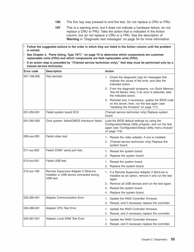
195 The Esc key was pressed to end the test. Do not replace a CRU or FRU.
197 This is a warning error, but it does not indicate a hardware failure; do not
replace a CRU or FRU. Take the action that is indicated in the Action
column, but do not replace a CRU or a FRU. See the description of
Warning in “Diagnostic text messages” on page 54 for more information.
v Follow the suggested actions in the order in which they are listed in the Action column until the problem
is solved.
v See Chapter 3, “Parts listing, Type 7977,” on page 79 to determine which components are customer
replaceable units (CRU) and which components are field replaceable units (FRU).
v If an action step is preceded by “(Trained service technician only),” that step must be performed only by a
trained service technician.
Error code Description Action
001-198-000 Test aborted. 1. Check the diagnostic logs for messages that
indicate the cause of the error, and take the
indicated action.
2. From the diagnostic programs, run Quick Memory
Test All Banks; then, if an error is detected, take
the indicated action.
3. Reinstall and, if necessary, update the BIOS code
on the server; then, run the test again (see
“Updating the firmware” on page 117).
001-250-001 Failed system board ECC (Trained service technician only) Replace system
board.
001-292-000 Core system: failed/CMOS checksum failed. Load the BIOS default settings by using the
Configuration/Setup Utility program, and run the test
again (see “Configuration/Setup Utility menu choices”
on page 119).
005-xxx-000 Failed video test. 1. Reseat the video adapter, if one is installed.
2. (Trained service technician only) Replace the
system board.
011-xxx-000 Failed COM1 serial port test. 1. Reseat the system board.
2. Replace the system board.
015-xxx-001 Failed USB test. 1. Reseat the system board.
2. Replace the system board.
015-xxx-198 Remote Supervisor Adapter II SlimLine
installed or USB device connected during
USB test.
1. If a Remote Supervisor Adapter II SlimLine is
installed as an option, remove it and run the test
again.
2. Remove all USB devices and run the test again.
3. Reseat the system board.
4. Replace the system board.
035-285-001 Adapter Communication Error 1. Update the RAID Controller firmware.
2. Reseat, and if necessary replace the controller.
035-286-001 Adapter CPU Test Error 1. Update the RAID Controller firmware.
2. Reseat, and if necessary replace the controller.
035-287-001 Adapter Local RAM Test Error 1. Update the RAID Controller firmware.
2. Reseat, and if necessary replace the controller.
Chapter 2. Diagnostics 55
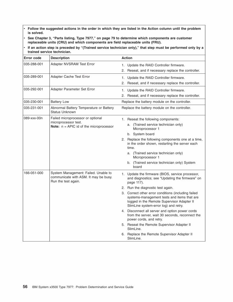
v Follow the suggested actions in the order in which they are listed in the Action column until the problem
is solved.
v See Chapter 3, “Parts listing, Type 7977,” on page 79 to determine which components are customer
replaceable units (CRU) and which components are field replaceable units (FRU).
v If an action step is preceded by “(Trained service technician only),” that step must be performed only by a
trained service technician.
Error code Description Action
035-288-001 Adapter NVSRAM Test Error 1. Update the RAID Controller firmware.
2. Reseat, and if necessary replace the controller.
035-289-001 Adapter Cache Test Error 1. Update the RAID Controller firmware.
2. Reseat, and if necessary replace the controller.
035-292-001 Adapter Parameter Set Error 1. Update the RAID Controller firmware.
2. Reseat, and if necessary replace the controller.
035-230-001 Battery Low Replace the battery module on the controller.
035-231-001 Abnormal Battery Temperature or Battery
Status Unknown
Replace the battery module on the controller.
089-xxx-00n Failed microprocessor or optional
microprocessor test.
Note: n = APIC id of the microprocessor
1. Reseat the following components:
a. (Trained service technician only)
Microprocessor 1
b. System board
2. Replace the following components one at a time,
in the order shown, restarting the server each
time.
a. (Trained service technician only)
Microprocessor 1
b. (Trained service technician only) System
board
166-051-000 System Management: Failed. Unable to
communicate with ASM. It may be busy.
Run the test again.
1. Update the firmware (BIOS, service processor,
and diagnostics; see “Updating the firmware” on
page 117).
2. Run the diagnostic test again.
3. Correct other error conditions (including failed
systems-management tests and items that are
logged in the Remote Supervisor Adapter II
SlimLine system-error log) and retry.
4. Disconnect all server and option power cords
from the server, wait 30 seconds, reconnect the
power cords, and retry.
5. Reseat the Remote Supervisor Adapter II
SlimLine.
6. Replace the Remote Supervisor Adapter II
SlimLine.
56 IBM System x3500 Type 7977: Problem Determination and Service Guide
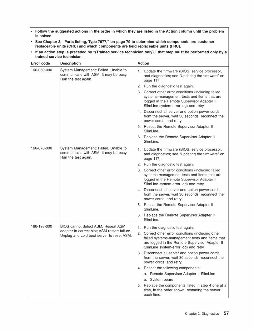
v Follow the suggested actions in the order in which they are listed in the Action column until the problem
is solved.
v See Chapter 3, “Parts listing, Type 7977,” on page 79 to determine which components are customer
replaceable units (CRU) and which components are field replaceable units (FRU).
v If an action step is preceded by “(Trained service technician only),” that step must be performed only by a
trained service technician.
Error code Description Action
166-060-000 System Management: Failed. Unable to
communicate with ASM. It may be busy.
Run the test again.
1. Update the firmware (BIOS, service processor,
and diagnostics; see “Updating the firmware” on
page 117).
2. Run the diagnostic test again.
3. Correct other error conditions (including failed
systems-management tests and items that are
logged in the Remote Supervisor Adapter II
SlimLine system-error log) and retry.
4. Disconnect all server and option power cords
from the server, wait 30 seconds, reconnect the
power cords, and retry.
5. Reseat the Remote Supervisor Adapter II
SlimLine.
6. Replace the Remote Supervisor Adapter II
SlimLine.
166-070-000 System Management: Failed. Unable to
communicate with ASM. It may be busy.
Run the test again.
1. Update the firmware (BIOS, service processor,
and diagnostics; see “Updating the firmware” on
page 117).
2. Run the diagnostic test again.
3. Correct other error conditions (including failed
systems-management tests and items that are
logged in the Remote Supervisor Adapter II
SlimLine system-error log) and retry.
4. Disconnect all server and option power cords
from the server, wait 30 seconds, reconnect the
power cords, and retry.
5. Reseat the Remote Supervisor Adapter II
SlimLine.
6. Replace the Remote Supervisor Adapter II
SlimLine.
166-198-000 BIOS cannot detect ASM. Reseat ASM
adapter in correct slot; ASM restart failure.
Unplug and cold boot server to reset ASM.
1. Run the diagnostic test again.
2. Correct other error conditions (including other
failed systems-management tests and items that
are logged in the Remote Supervisor Adapter II
SlimLine system-error log) and retry.
3. Disconnect all server and option power cords
from the server, wait 30 seconds, reconnect the
power cords, and retry.
4. Reseat the following components:
a. Remote Supervisor Adapter II SlimLine
b. System board
5. Replace the components listed in step 4 one at a
time, in the order shown, restarting the server
each time.
Chapter 2. Diagnostics 57
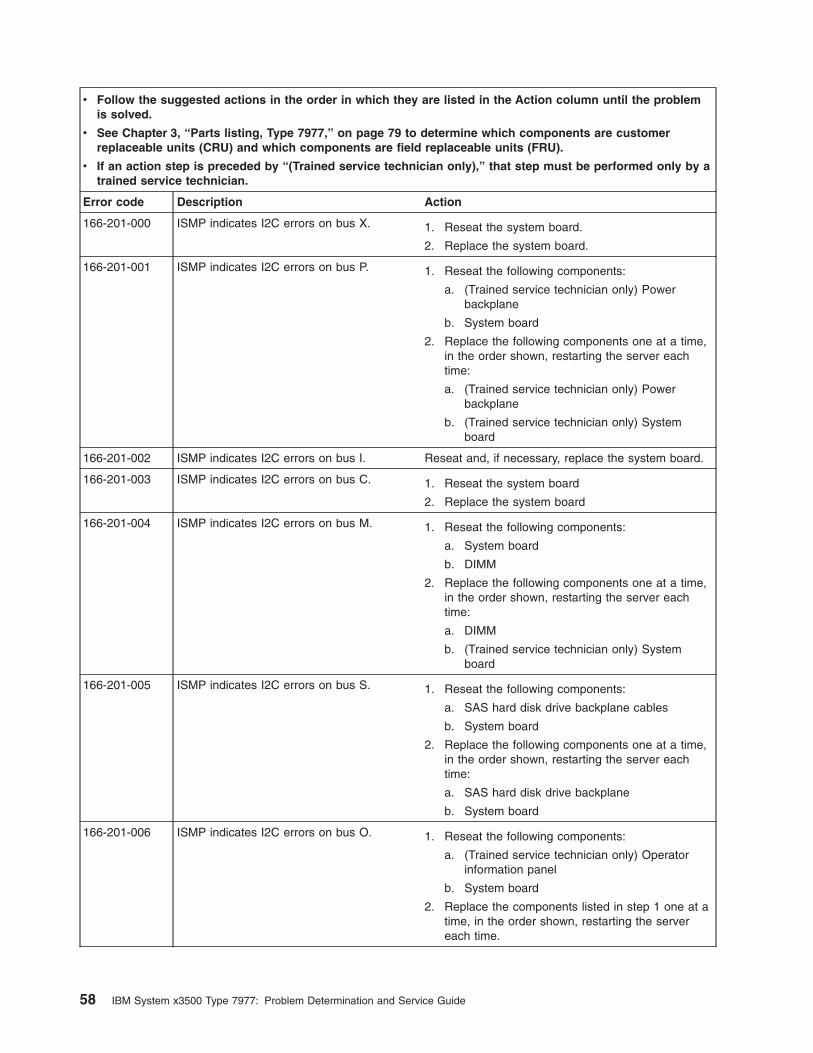
v Follow the suggested actions in the order in which they are listed in the Action column until the problem
is solved.
v See Chapter 3, “Parts listing, Type 7977,” on page 79 to determine which components are customer
replaceable units (CRU) and which components are field replaceable units (FRU).
v If an action step is preceded by “(Trained service technician only),” that step must be performed only by a
trained service technician.
Error code Description Action
166-201-000 ISMP indicates I2C errors on bus X. 1. Reseat the system board.
2. Replace the system board.
166-201-001 ISMP indicates I2C errors on bus P. 1. Reseat the following components:
a. (Trained service technician only) Power
backplane
b. System board
2. Replace the following components one at a time,
in the order shown, restarting the server each
time:
a. (Trained service technician only) Power
backplane
b. (Trained service technician only) System
board
166-201-002 ISMP indicates I2C errors on bus I. Reseat and, if necessary, replace the system board.
166-201-003 ISMP indicates I2C errors on bus C. 1. Reseat the system board
2. Replace the system board
166-201-004 ISMP indicates I2C errors on bus M. 1. Reseat the following components:
a. System board
b. DIMM
2. Replace the following components one at a time,
in the order shown, restarting the server each
time:
a. DIMM
b. (Trained service technician only) System
board
166-201-005 ISMP indicates I2C errors on bus S. 1. Reseat the following components:
a. SAS hard disk drive backplane cables
b. System board
2. Replace the following components one at a time,
in the order shown, restarting the server each
time:
a. SAS hard disk drive backplane
b. System board
166-201-006 ISMP indicates I2C errors on bus O. 1. Reseat the following components:
a. (Trained service technician only) Operator
information panel
b. System board
2. Replace the components listed in step 1 one at a
time, in the order shown, restarting the server
each time.
58 IBM System x3500 Type 7977: Problem Determination and Service Guide
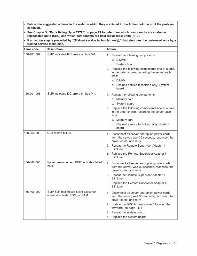
v Follow the suggested actions in the order in which they are listed in the Action column until the problem
is solved.
v See Chapter 3, “Parts listing, Type 7977,” on page 79 to determine which components are customer
replaceable units (CRU) and which components are field replaceable units (FRU).
v If an action step is preceded by “(Trained service technician only),” that step must be performed only by a
trained service technician.
Error code Description Action
166-201-007 ISMP indicates I2C errors on bus M0. 1. Reseat the following components:
a. DIMMs
b. System board
2. Replace the following components one at a time,
in the order shown, restarting the server each
time:
a. DIMMs
b. (Trained service technician only) System
board
166-201-008 ISMP indicates I2C errors on bus M1. 1. Reseat the following components:
a. Memory card
b. System board
2. Replace the following components one at a time,
in the order shown, restarting the server each
time:
a. Memory card
b. (Trained service technician only) System
board
166-260-000 ASM restart failure. 1. Disconnect all server and option power cords
from the server, wait 30 seconds, reconnect the
power cords, and retry.
2. Reseat the Remote Supervisor Adapter II
SlimLine.
3. Replace the Remote Supervisor Adapter II
SlimLine.
166-342-000 System management BIST indicates failed
tests.
1. Disconnect all server and option power cords
from the server, wait 30 seconds, reconnect the
power cords, and retry.
2. Reseat the Remote Supervisor Adapter II
SlimLine.
3. Replace the Remote Supervisor Adapter II
SlimLine.
166-400-000 ISMP Self Test Result failed tests: xxx
where xxx=flash, ROM, or RAM.
1. Disconnect all server and option power cords
from the server, wait 30 seconds, reconnect the
power cords, and retry.
2. Update the BMC firmware (see “Updating the
firmware” on page 117).
3. Reseat the system board.
4. Replace the system board.
Chapter 2. Diagnostics 59
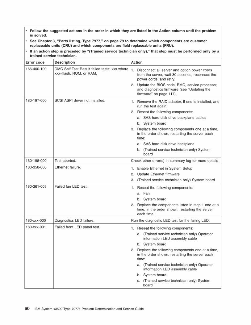
v Follow the suggested actions in the order in which they are listed in the Action column until the problem
is solved.
v See Chapter 3, “Parts listing, Type 7977,” on page 79 to determine which components are customer
replaceable units (CRU) and which components are field replaceable units (FRU).
v If an action step is preceded by “(Trained service technician only),” that step must be performed only by a
trained service technician.
Error code Description Action
166-400-100 DMC Self Test Result failed tests: xxx where
xxx=flash, ROM, or RAM.
1. Disconnect all server and option power cords
from the server, wait 30 seconds, reconnect the
power cords, and retry.
2. Update the BIOS code, BMC, service processor,
and diagnostics firmware (see “Updating the
firmware” on page 117).
180-197-000 SCSI ASPI driver not installed. 1. Remove the RAID adapter, if one is installed, and
run the test again.
2. Reseat the following components:
a. SAS hard disk drive backplane cables
b. System board
3. Replace the following components one at a time,
in the order shown, restarting the server each
time:
a. SAS hard disk drive backplane
b. (Trained service technician only) System
board
180-198-000 Test aborted. Check other error(s) in summary log for more details
180-358-000 Ethernet failure. 1. Enable Ethernet in System Setup
2. Update Ethernet firmware
3. (Trained service technician only) System board
180-361-003 Failed fan LED test. 1. Reseat the following components:
a. Fan
b. System board
2. Replace the components listed in step 1 one at a
time, in the order shown, restarting the server
each time.
180-xxx-000 Diagnostics LED failure. Run the diagnostic LED test for the failing LED.
180-xxx-001 Failed front LED panel test. 1. Reseat the following components:
a. (Trained service technician only) Operator
information LED assembly cable
b. System board
2. Replace the following components one at a time,
in the order shown, restarting the server each
time:
a. (Trained service technician only) Operator
information LED assembly cable
b. System board
c. (Trained service technician only) System
board
60 IBM System x3500 Type 7977: Problem Determination and Service Guide
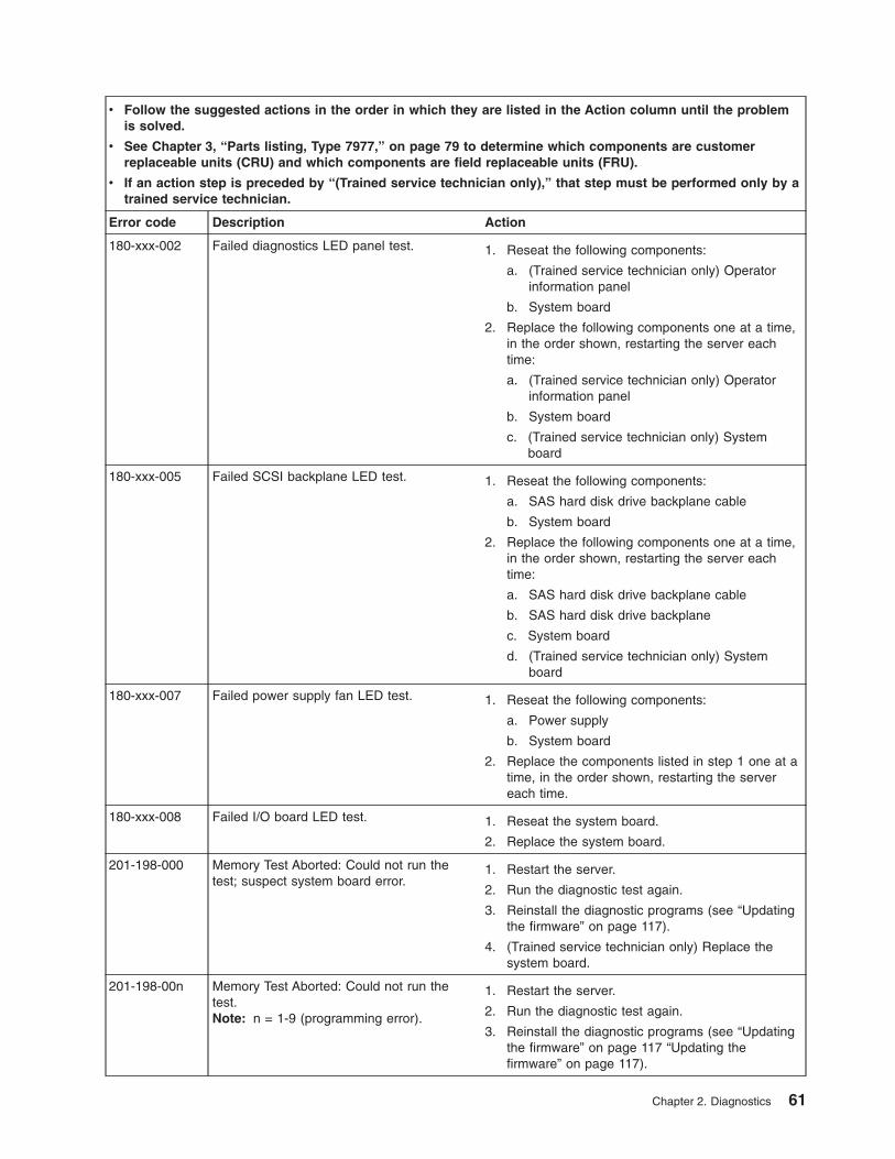
v Follow the suggested actions in the order in which they are listed in the Action column until the problem
is solved.
v See Chapter 3, “Parts listing, Type 7977,” on page 79 to determine which components are customer
replaceable units (CRU) and which components are field replaceable units (FRU).
v If an action step is preceded by “(Trained service technician only),” that step must be performed only by a
trained service technician.
Error code Description Action
180-xxx-002 Failed diagnostics LED panel test. 1. Reseat the following components:
a. (Trained service technician only) Operator
information panel
b. System board
2. Replace the following components one at a time,
in the order shown, restarting the server each
time:
a. (Trained service technician only) Operator
information panel
b. System board
c. (Trained service technician only) System
board
180-xxx-005 Failed SCSI backplane LED test. 1. Reseat the following components:
a. SAS hard disk drive backplane cable
b. System board
2. Replace the following components one at a time,
in the order shown, restarting the server each
time:
a. SAS hard disk drive backplane cable
b. SAS hard disk drive backplane
c. System board
d. (Trained service technician only) System
board
180-xxx-007 Failed power supply fan LED test. 1. Reseat the following components:
a. Power supply
b. System board
2. Replace the components listed in step 1 one at a
time, in the order shown, restarting the server
each time.
180-xxx-008 Failed I/O board LED test. 1. Reseat the system board.
2. Replace the system board.
201-198-000 Memory Test Aborted: Could not run the
test; suspect system board error.
1. Restart the server.
2. Run the diagnostic test again.
3. Reinstall the diagnostic programs (see “Updating
the firmware” on page 117).
4. (Trained service technician only) Replace the
system board.
201-198-00n Memory Test Aborted: Could not run the
test.
Note: n = 1-9 (programming error).
1. Restart the server.
2. Run the diagnostic test again.
3. Reinstall the diagnostic programs (see “Updating
the firmware” on page 117 “Updating the
firmware” on page 117).
Chapter 2. Diagnostics 61
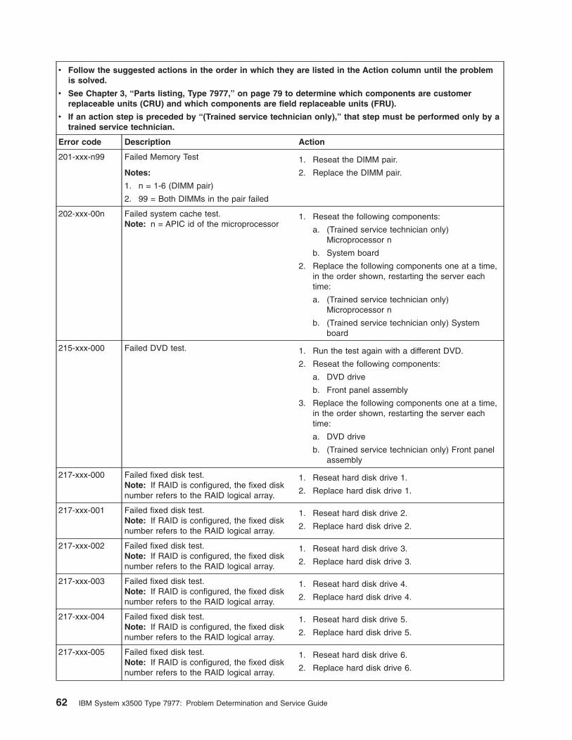
v Follow the suggested actions in the order in which they are listed in the Action column until the problem
is solved.
v See Chapter 3, “Parts listing, Type 7977,” on page 79 to determine which components are customer
replaceable units (CRU) and which components are field replaceable units (FRU).
v If an action step is preceded by “(Trained service technician only),” that step must be performed only by a
trained service technician.
Error code Description Action
201-xxx-n99 Failed Memory Test
Notes:
1. n = 1-6 (DIMM pair)
2. 99 = Both DIMMs in the pair failed
1. Reseat the DIMM pair.
2. Replace the DIMM pair.
202-xxx-00n Failed system cache test.
Note: n = APIC id of the microprocessor
1. Reseat the following components:
a. (Trained service technician only)
Microprocessor n
b. System board
2. Replace the following components one at a time,
in the order shown, restarting the server each
time:
a. (Trained service technician only)
Microprocessor n
b. (Trained service technician only) System
board
215-xxx-000 Failed DVD test. 1. Run the test again with a different DVD.
2. Reseat the following components:
a. DVD drive
b. Front panel assembly
3. Replace the following components one at a time,
in the order shown, restarting the server each
time:
a. DVD drive
b. (Trained service technician only) Front panel
assembly
217-xxx-000 Failed fixed disk test.
Note: If RAID is configured, the fixed disk
number refers to the RAID logical array.
1. Reseat hard disk drive 1.
2. Replace hard disk drive 1.
217-xxx-001 Failed fixed disk test.
Note: If RAID is configured, the fixed disk
number refers to the RAID logical array.
1. Reseat hard disk drive 2.
2. Replace hard disk drive 2.
217-xxx-002 Failed fixed disk test.
Note: If RAID is configured, the fixed disk
number refers to the RAID logical array.
1. Reseat hard disk drive 3.
2. Replace hard disk drive 3.
217-xxx-003 Failed fixed disk test.
Note: If RAID is configured, the fixed disk
number refers to the RAID logical array.
1. Reseat hard disk drive 4.
2. Replace hard disk drive 4.
217-xxx-004 Failed fixed disk test.
Note: If RAID is configured, the fixed disk
number refers to the RAID logical array.
1. Reseat hard disk drive 5.
2. Replace hard disk drive 5.
217-xxx-005 Failed fixed disk test.
Note: If RAID is configured, the fixed disk
number refers to the RAID logical array.
1. Reseat hard disk drive 6.
2. Replace hard disk drive 6.
62 IBM System x3500 Type 7977: Problem Determination and Service Guide
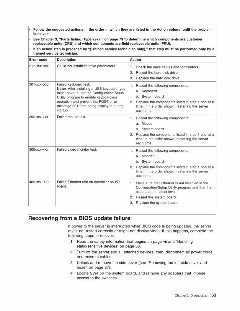
v Follow the suggested actions in the order in which they are listed in the Action column until the problem
is solved.
v See Chapter 3, “Parts listing, Type 7977,” on page 79 to determine which components are customer
replaceable units (CRU) and which components are field replaceable units (FRU).
v If an action step is preceded by “(Trained service technician only),” that step must be performed only by a
trained service technician.
Error code Description Action
217-198-xxx Could not establish drive parameters. 1. Check the drive cables and terminators.
2. Reseat the hard disk drive.
3. Replace the hard disk drive.
301-xxx-000 Failed keyboard test.
Note: After installing a USB keyboard, you
might have to use the Configuration/Setup
Utility program to enable keyboardless
operation and prevent the POST error
message 301 from being displayed during
startup.
1. Reseat the following components:
a. Keyboard
b. System board
2. Replace the components listed in step 1 one at a
time, in the order shown, restarting the server
each time.
302-xxx-xxx Failed mouse test. 1. Reseat the following components:
a. Mouse
b. System board
2. Replace the components listed in step 1 one at a
time, in the order shown, restarting the server
each time.
305-xxx-xxx Failed video monitor test. 1. Reseat the following components:
a. Monitor
b. System board
2. Replace the components listed in step 1 one at a
time, in the order shown, restarting the server
each time.
405-xxx-000 Failed Ethernet test on controller on I/O
board.
1. Make sure that Ethernet is not disabled in the
Configuration/Setup Utility program and that the
code is at the latest level.
2. Reseat the system board.
3. Replace the system board.
Recovering from a BIOS update failure
If power to the server is interrupted while BIOS code is being updated, the server
might not restart correctly or might not display video. If this happens, complete the
following steps to recover:
1. Read the safety information that begins on page vii and “Handling
static-sensitive devices” on page 86.
2. Turn off the server and all attached devices; then, disconnect all power cords
and external cables.
3. Unlock and remove the side cover (see “Removing the left-side cover and
bezel” on page 87).
4. Locate SW4 on the system board, and remove any adapters that impede
access to the switches.
Chapter 2. Diagnostics 63
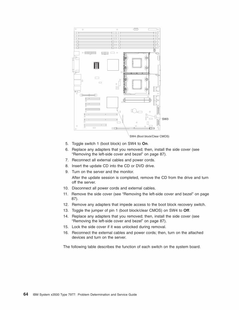
123456
789
101112
DIMM LEDs
SW4 (Boot block/Clear CMOS)
SW3
5. Toggle switch 1 (boot block) on SW4 to On.
6. Replace any adapters that you removed; then, install the side cover (see
“Removing the left-side cover and bezel” on page 87).
7. Reconnect all external cables and power cords.
8. Insert the update CD into the CD or DVD drive.
9. Turn on the server and the monitor.
After the update session is completed, remove the CD from the drive and turn
off the server.
10. Disconnect all power cords and external cables.
11. Remove the side cover (see “Removing the left-side cover and bezel” on page
87).
12. Remove any adapters that impede access to the boot block recovery switch.
13. Toggle the jumper of pin 1 (boot block/clear CMOS) on SW4 to Off.
14. Replace any adapters that you removed; then, install the side cover (see
“Removing the left-side cover and bezel” on page 87).
15. Lock the side cover if it was unlocked during removal.
16. Reconnect the external cables and power cords; then, turn on the attached
devices and turn on the server.
The following table describes the function of each switch on the system board.
64 IBM System x3500 Type 7977: Problem Determination and Service Guide
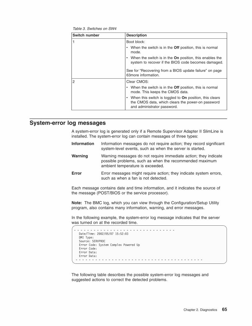
Table 3. Switches on SW4
Switch number Description
1 Boot block:
v When the switch is in the Off position, this is normal
mode.
v When the switch is in the On position, this enables the
system to recover if the BIOS code becomes damaged.
See for “Recovering from a BIOS update failure” on page
63more information.
2 Clear CMOS:
v When the switch is in the Off position, this is normal
mode. This keeps the CMOS data.
v When this switch is toggled to On position, this clears
the CMOS data, which clears the power-on password
and administrator password.
System-error log messages
A system-error log is generated only if a Remote Supervisor Adapter II SlimLine is
installed. The system-error log can contain messages of three types:
Information Information messages do not require action; they record significant
system-level events, such as when the server is started.
Warning Warning messages do not require immediate action; they indicate
possible problems, such as when the recommended maximum
ambient temperature is exceeded.
Error Error messages might require action; they indicate system errors,
such as when a fan is not detected.
Each message contains date and time information, and it indicates the source of
the message (POST/BIOS or the service processor).
Note: The BMC log, which you can view through the Configuration/Setup Utility
program, also contains many information, warning, and error messages.
In the following example, the system-error log message indicates that the server
was turned on at the recorded time.
- - - - - - - - - - - - - - - - - - - - - - - - - - - - - - -
Date/Time: 2002/05/07 15:52:03
DMI Type:
Source: SERVPROC
Error Code: System Complex Powered Up
Error Code:
Error Data:
Error Data:
- - - - - - - - - - - - - - - - - - - - - - - - - - - - - - - - - - - - - - -
The following table describes the possible system-error log messages and
suggested actions to correct the detected problems.
Chapter 2. Diagnostics 65
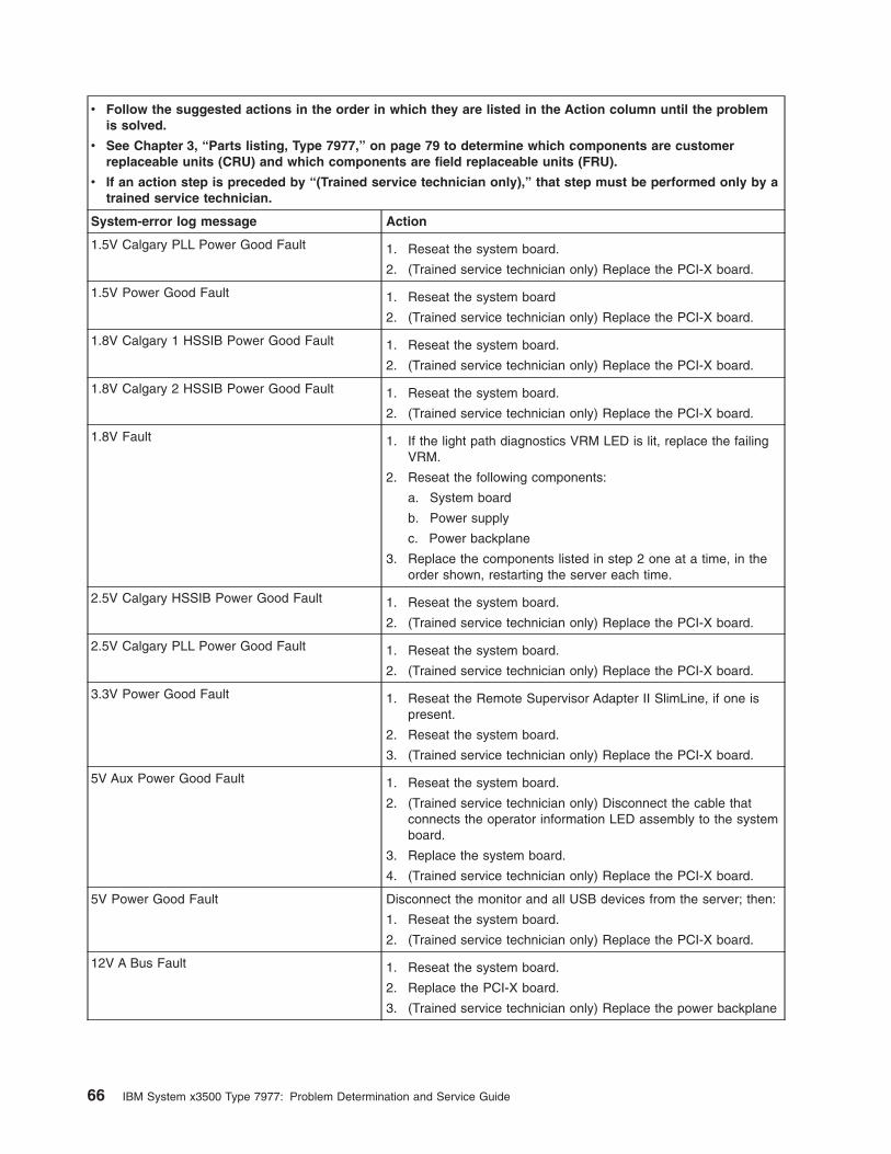
v Follow the suggested actions in the order in which they are listed in the Action column until the problem
is solved.
v See Chapter 3, “Parts listing, Type 7977,” on page 79 to determine which components are customer
replaceable units (CRU) and which components are field replaceable units (FRU).
v If an action step is preceded by “(Trained service technician only),” that step must be performed only by a
trained service technician.
System-error log message Action
1.5V Calgary PLL Power Good Fault 1. Reseat the system board.
2. (Trained service technician only) Replace the PCI-X board.
1.5V Power Good Fault 1. Reseat the system board
2. (Trained service technician only) Replace the PCI-X board.
1.8V Calgary 1 HSSIB Power Good Fault 1. Reseat the system board.
2. (Trained service technician only) Replace the PCI-X board.
1.8V Calgary 2 HSSIB Power Good Fault 1. Reseat the system board.
2. (Trained service technician only) Replace the PCI-X board.
1.8V Fault 1. If the light path diagnostics VRM LED is lit, replace the failing
VRM.
2. Reseat the following components:
a. System board
b. Power supply
c. Power backplane
3. Replace the components listed in step 2 one at a time, in the
order shown, restarting the server each time.
2.5V Calgary HSSIB Power Good Fault 1. Reseat the system board.
2. (Trained service technician only) Replace the PCI-X board.
2.5V Calgary PLL Power Good Fault 1. Reseat the system board.
2. (Trained service technician only) Replace the PCI-X board.
3.3V Power Good Fault 1. Reseat the Remote Supervisor Adapter II SlimLine, if one is
present.
2. Reseat the system board.
3. (Trained service technician only) Replace the PCI-X board.
5V Aux Power Good Fault 1. Reseat the system board.
2. (Trained service technician only) Disconnect the cable that
connects the operator information LED assembly to the system
board.
3. Replace the system board.
4. (Trained service technician only) Replace the PCI-X board.
5V Power Good Fault Disconnect the monitor and all USB devices from the server; then:
1. Reseat the system board.
2. (Trained service technician only) Replace the PCI-X board.
12V A Bus Fault 1. Reseat the system board.
2. Replace the PCI-X board.
3. (Trained service technician only) Replace the power backplane
66 IBM System x3500 Type 7977: Problem Determination and Service Guide
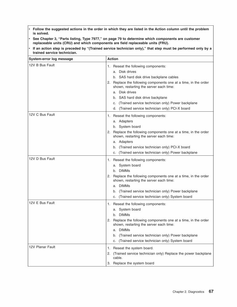
v Follow the suggested actions in the order in which they are listed in the Action column until the problem
is solved.
v See Chapter 3, “Parts listing, Type 7977,” on page 79 to determine which components are customer
replaceable units (CRU) and which components are field replaceable units (FRU).
v If an action step is preceded by “(Trained service technician only),” that step must be performed only by a
trained service technician.
System-error log message Action
12V B Bus Fault 1. Reseat the following components:
a. Disk drives
b. SAS hard disk drive backplane cables
2. Replace the following components one at a time, in the order
shown, restarting the server each time:
a. Disk drives
b. SAS hard disk drive backplane
c. (Trained service technician only) Power backplane
d. (Trained service technician only) PCI-X board
12V C Bus Fault 1. Reseat the following components:
a. Adapters
b. System board
2. Replace the following components one at a time, in the order
shown, restarting the server each time:
a. Adapters
b. (Trained service technician only) PCI-X board
c. (Trained service technician only) Power backplane
12V D Bus Fault 1. Reseat the following components:
a. System board
b. DIMMs
2. Replace the following components one at a time, in the order
shown, restarting the server each time:
a. DIMMs
b. (Trained service technician only) Power backplane
c. (Trained service technician only) System board
12V E Bus Fault 1. Reseat the following components:
a. System board
b. DIMMs
2. Replace the following components one at a time, in the order
shown, restarting the server each time:
a. DIMMs
b. (Trained service technician only) Power backplane
c. (Trained service technician only) System board
12V Planar Fault 1. Reseat the system board.
2. (Trained service technician only) Replace the power backplane
cable.
3. Replace the system board
Chapter 2. Diagnostics 67
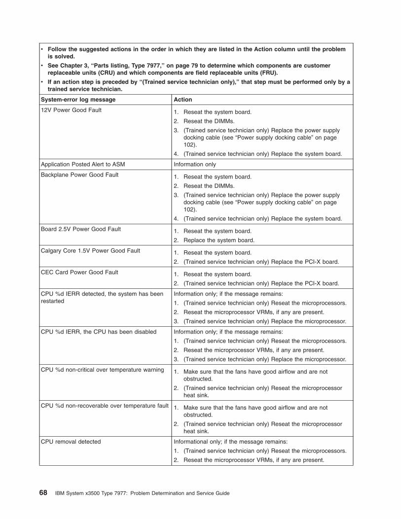
v Follow the suggested actions in the order in which they are listed in the Action column until the problem
is solved.
v See Chapter 3, “Parts listing, Type 7977,” on page 79 to determine which components are customer
replaceable units (CRU) and which components are field replaceable units (FRU).
v If an action step is preceded by “(Trained service technician only),” that step must be performed only by a
trained service technician.
System-error log message Action
12V Power Good Fault 1. Reseat the system board.
2. Reseat the DIMMs.
3. (Trained service technician only) Replace the power supply
docking cable (see “Power supply docking cable” on page
102).
4. (Trained service technician only) Replace the system board.
Application Posted Alert to ASM Information only
Backplane Power Good Fault 1. Reseat the system board.
2. Reseat the DIMMs.
3. (Trained service technician only) Replace the power supply
docking cable (see “Power supply docking cable” on page
102).
4. (Trained service technician only) Replace the system board.
Board 2.5V Power Good Fault 1. Reseat the system board.
2. Replace the system board.
Calgary Core 1.5V Power Good Fault 1. Reseat the system board.
2. (Trained service technician only) Replace the PCI-X board.
CEC Card Power Good Fault 1. Reseat the system board.
2. (Trained service technician only) Replace the PCI-X board.
CPU %d IERR detected, the system has been
restarted
Information only; if the message remains:
1. (Trained service technician only) Reseat the microprocessors.
2. Reseat the microprocessor VRMs, if any are present.
3. (Trained service technician only) Replace the microprocessor.
CPU %d IERR, the CPU has been disabled Information only; if the message remains:
1. (Trained service technician only) Reseat the microprocessors.
2. Reseat the microprocessor VRMs, if any are present.
3. (Trained service technician only) Replace the microprocessor.
CPU %d non-critical over temperature warning 1. Make sure that the fans have good airflow and are not
obstructed.
2. (Trained service technician only) Reseat the microprocessor
heat sink.
CPU %d non-recoverable over temperature fault 1. Make sure that the fans have good airflow and are not
obstructed.
2. (Trained service technician only) Reseat the microprocessor
heat sink.
CPU removal detected Informational only; if the message remains:
1. (Trained service technician only) Reseat the microprocessors.
2. Reseat the microprocessor VRMs, if any are present.
68 IBM System x3500 Type 7977: Problem Determination and Service Guide
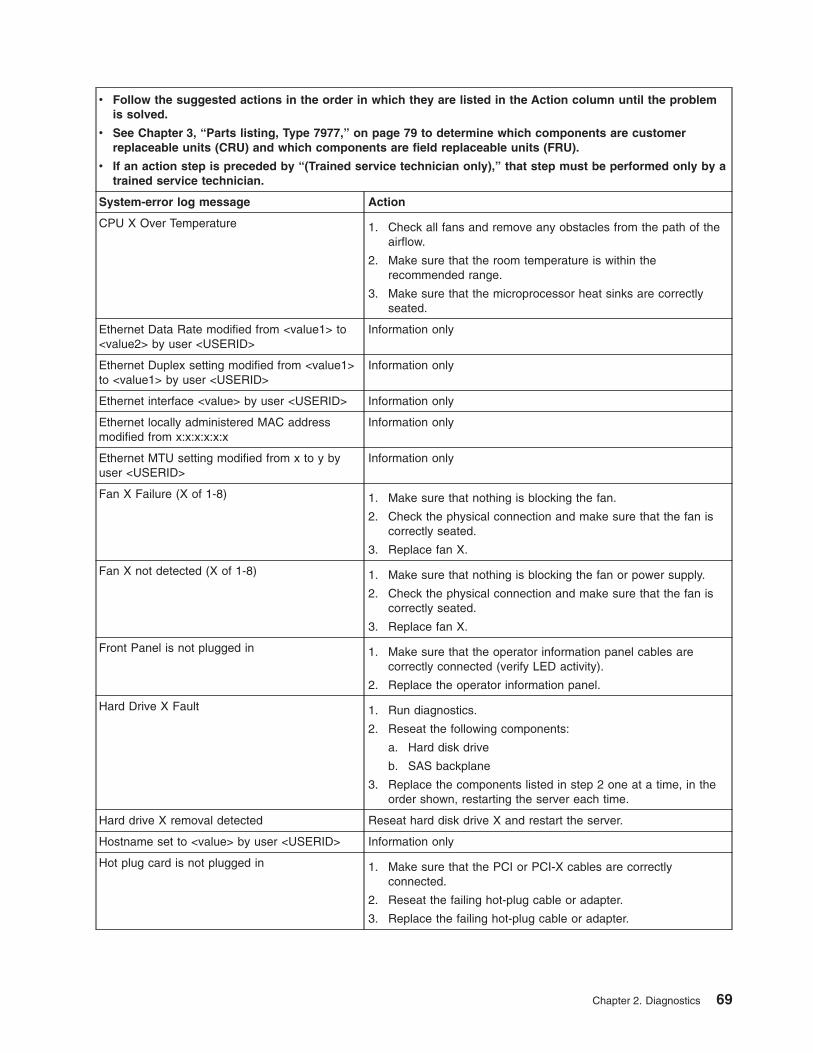
v Follow the suggested actions in the order in which they are listed in the Action column until the problem
is solved.
v See Chapter 3, “Parts listing, Type 7977,” on page 79 to determine which components are customer
replaceable units (CRU) and which components are field replaceable units (FRU).
v If an action step is preceded by “(Trained service technician only),” that step must be performed only by a
trained service technician.
System-error log message Action
CPU X Over Temperature 1. Check all fans and remove any obstacles from the path of the
airflow.
2. Make sure that the room temperature is within the
recommended range.
3. Make sure that the microprocessor heat sinks are correctly
seated.
Ethernet Data Rate modified from <value1> to
<value2> by user <USERID>
Information only
Ethernet Duplex setting modified from <value1>
to <value1> by user <USERID>
Information only
Ethernet interface <value> by user <USERID> Information only
Ethernet locally administered MAC address
modified from x:x:x:x:x:x
Information only
Ethernet MTU setting modified from x to y by
user <USERID>
Information only
Fan X Failure (X of 1-8) 1. Make sure that nothing is blocking the fan.
2. Check the physical connection and make sure that the fan is
correctly seated.
3. Replace fan X.
Fan X not detected (X of 1-8) 1. Make sure that nothing is blocking the fan or power supply.
2. Check the physical connection and make sure that the fan is
correctly seated.
3. Replace fan X.
Front Panel is not plugged in 1. Make sure that the operator information panel cables are
correctly connected (verify LED activity).
2. Replace the operator information panel.
Hard Drive X Fault 1. Run diagnostics.
2. Reseat the following components:
a. Hard disk drive
b. SAS backplane
3. Replace the components listed in step 2 one at a time, in the
order shown, restarting the server each time.
Hard drive X removal detected Reseat hard disk drive X and restart the server.
Hostname set to <value> by user <USERID> Information only
Hot plug card is not plugged in 1. Make sure that the PCI or PCI-X cables are correctly
connected.
2. Reseat the failing hot-plug cable or adapter.
3. Replace the failing hot-plug cable or adapter.
Chapter 2. Diagnostics 69
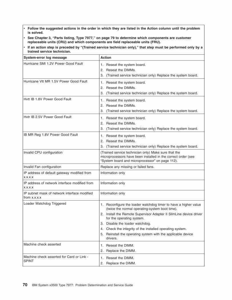
v Follow the suggested actions in the order in which they are listed in the Action column until the problem
is solved.
v See Chapter 3, “Parts listing, Type 7977,” on page 79 to determine which components are customer
replaceable units (CRU) and which components are field replaceable units (FRU).
v If an action step is preceded by “(Trained service technician only),” that step must be performed only by a
trained service technician.
System-error log message Action
Hurricane SMI 1.2V Power Good Fault 1. Reseat the system board.
2. Reseat the DIMMs.
3. (Trained service technician only) Replace the system board.
Hurricane Vtt MR 1.5V Power Good Fault 1. Reseat the system board.
2. Reseat the DIMMs.
3. (Trained service technician only) Replace the system board.
Hvtt IB 1.8V Power Good Fault 1. Reseat the system board.
2. Reseat the DIMMs.
3. (Trained service technician only) Replace the system board.
Hvtr IB 2.5V Power Good Fault 1. Reseat the system board.
2. Reseat the DIMMs.
3. (Trained service technician only) Replace the system board.
IB MR Reg 1.8V Power Good Fault 1. Reseat the system board.
2. Reseat the DIMMs.
3. (Trained service technician only) Replace the system board.
Invalid CPU configuration (Trained service technician only) Make sure that the
microprocessors have been installed in the correct order (see
“System board and microprocessor” on page 112).
Invalid Fan configuration Replace any missing or failed fans.
IP address of default gateway modified from
x.x.x.x
Information only
IP address of network interface modified from
x.x.x.x
Information only
IP subnet mask of network interface modified
from x.x.x.x
Information only
Loader Watchdog Triggered 1. Reconfigure the loader watchdog timer to have a higher value
(twice the normal operating-system boot time).
2. Install the Remote Supervisor Adapter II SlimLine device driver
for the operating system.
3. Disable the loader watchdog.
4. Check the integrity of the installed operating system.
5. Reinstall the operating system with the applicable device
drivers.
Machine check asserted 1. Reseat the DIMM.
2. Replace the DIMM.
Machine check asserted for Card or Link -
SPINT
1. Reseat the DIMM.
2. Replace the DIMM.
70 IBM System x3500 Type 7977: Problem Determination and Service Guide
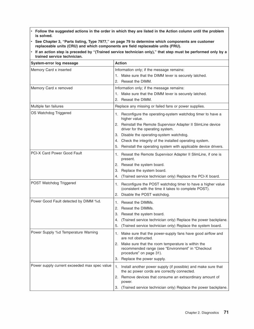
v Follow the suggested actions in the order in which they are listed in the Action column until the problem
is solved.
v See Chapter 3, “Parts listing, Type 7977,” on page 79 to determine which components are customer
replaceable units (CRU) and which components are field replaceable units (FRU).
v If an action step is preceded by “(Trained service technician only),” that step must be performed only by a
trained service technician.
System-error log message Action
Memory Card x inserted Information only; if the message remains:
1. Make sure that the DIMM lever is securely latched.
2. Reseat the DIMM.
Memory Card x removed Information only; if the message remains:
1. Make sure that the DIMM lever is securely latched.
2. Reseat the DIMM.
Multiple fan failures Replace any missing or failed fans or power supplies.
OS Watchdog Triggered 1. Reconfigure the operating-system watchdog timer to have a
higher value.
2. Reinstall the Remote Supervisor Adapter II SlimLine device
driver for the operating system.
3. Disable the operating-system watchdog.
4. Check the integrity of the installed operating system.
5. Reinstall the operating system with applicable device drivers.
PCI-X Card Power Good Fault 1. Reseat the Remote Supervisor Adapter II SlimLine, if one is
present.
2. Reseat the system board.
3. Replace the system board.
4. (Trained service technician only) Replace the PCI-X board.
POST Watchdog Triggered 1. Reconfigure the POST watchdog timer to have a higher value
(consistent with the time it takes to complete POST).
2. Disable the POST watchdog.
Power Good Fault detected by DIMM %d. 1. Reseat the DIMMs.
2. Reseat the DIMMs.
3. Reseat the system board.
4. (Trained service technician only) Replace the power backplane.
5. (Trained service technician only) Replace the system board.
Power Supply %d Temperature Warning 1. Make sure that the power-supply fans have good airflow and
are not obstructed.
2. Make sure that the room temperature is within the
recommended range (see “Environment” in “Checkout
procedure” on page 31).
3. Replace the power supply.
Power supply current exceeded max spec value 1. Install another power supply (if possible) and make sure that
the ac power cords are correctly connected.
2. Remove devices that consume an extraordinary amount of
power.
3. (Trained service technician only) Replace the power backplane.
Chapter 2. Diagnostics 71
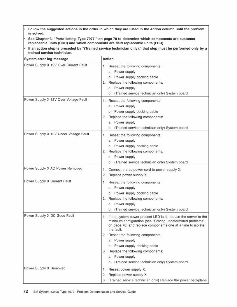
v Follow the suggested actions in the order in which they are listed in the Action column until the problem
is solved.
v See Chapter 3, “Parts listing, Type 7977,” on page 79 to determine which components are customer
replaceable units (CRU) and which components are field replaceable units (FRU).
v If an action step is preceded by “(Trained service technician only),” that step must be performed only by a
trained service technician.
System-error log message Action
Power Supply X 12V Over Current Fault 1. Reseat the following components:
a. Power supply
b. Power supply docking cable
2. Replace the following components:
a. Power supply
b. (Trained service technician only) System board
Power Supply X 12V Over Voltage Fault 1. Reseat the following components:
a. Power supply
b. Power supply docking cable
2. Replace the following components:
a. Power supply
b. (Trained service technician only) System board
Power Supply X 12V Under Voltage Fault 1. Reseat the following components:
a. Power supply
b. Power supply docking cable
2. Replace the following components:
a. Power supply
b. (Trained service technician only) System board
Power Supply X AC Power Removed 1. Connect the ac power cord to power supply X.
2. Replace power supply X.
Power Supply X Current Fault 1. Reseat the following components:
a. Power supply
b. Power supply docking cable
2. Replace the following components:
a. Power supply
b. (Trained service technician only) System board
Power Supply X DC Good Fault 1. If the system power present LED is lit, reduce the server to the
minimum configuration (see “Solving undetermined problems”
on page 76) and replace components one at a time to isolate
the fault.
2. Reseat the following components:
a. Power supply
b. Power supply docking cable
3. Replace the following components:
a. Power supply
b. (Trained service technician only) System board
Power Supply X Removed 1. Reseat power supply X.
2. Replace power supply X.
3. (Trained service technician only) Replace the power backplane.
72 IBM System x3500 Type 7977: Problem Determination and Service Guide
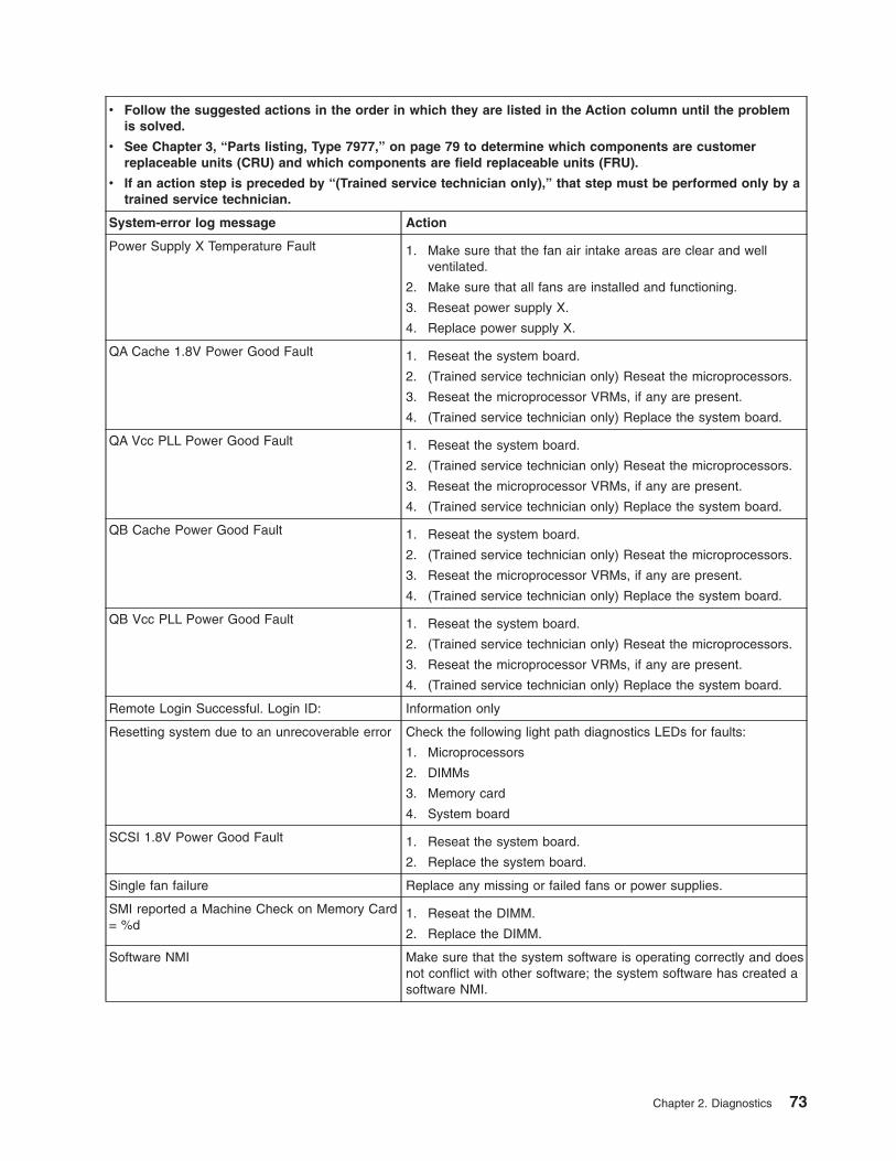
v Follow the suggested actions in the order in which they are listed in the Action column until the problem
is solved.
v See Chapter 3, “Parts listing, Type 7977,” on page 79 to determine which components are customer
replaceable units (CRU) and which components are field replaceable units (FRU).
v If an action step is preceded by “(Trained service technician only),” that step must be performed only by a
trained service technician.
System-error log message Action
Power Supply X Temperature Fault 1. Make sure that the fan air intake areas are clear and well
ventilated.
2. Make sure that all fans are installed and functioning.
3. Reseat power supply X.
4. Replace power supply X.
QA Cache 1.8V Power Good Fault 1. Reseat the system board.
2. (Trained service technician only) Reseat the microprocessors.
3. Reseat the microprocessor VRMs, if any are present.
4. (Trained service technician only) Replace the system board.
QA Vcc PLL Power Good Fault 1. Reseat the system board.
2. (Trained service technician only) Reseat the microprocessors.
3. Reseat the microprocessor VRMs, if any are present.
4. (Trained service technician only) Replace the system board.
QB Cache Power Good Fault 1. Reseat the system board.
2. (Trained service technician only) Reseat the microprocessors.
3. Reseat the microprocessor VRMs, if any are present.
4. (Trained service technician only) Replace the system board.
QB Vcc PLL Power Good Fault 1. Reseat the system board.
2. (Trained service technician only) Reseat the microprocessors.
3. Reseat the microprocessor VRMs, if any are present.
4. (Trained service technician only) Replace the system board.
Remote Login Successful. Login ID: Information only
Resetting system due to an unrecoverable error Check the following light path diagnostics LEDs for faults:
1. Microprocessors
2. DIMMs
3. Memory card
4. System board
SCSI 1.8V Power Good Fault 1. Reseat the system board.
2. Replace the system board.
Single fan failure Replace any missing or failed fans or power supplies.
SMI reported a Machine Check on Memory Card
= %d
1. Reseat the DIMM.
2. Replace the DIMM.
Software NMI Make sure that the system software is operating correctly and does
not conflict with other software; the system software has created a
software NMI.
Chapter 2. Diagnostics 73
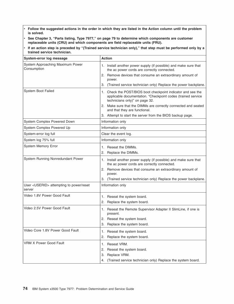
v Follow the suggested actions in the order in which they are listed in the Action column until the problem
is solved.
v See Chapter 3, “Parts listing, Type 7977,” on page 79 to determine which components are customer
replaceable units (CRU) and which components are field replaceable units (FRU).
v If an action step is preceded by “(Trained service technician only),” that step must be performed only by a
trained service technician.
System-error log message Action
System Approaching Maximum Power
Consumption
1. Install another power supply (if possible) and make sure that
the ac power cords are correctly connected.
2. Remove devices that consume an extraordinary amount of
power.
3. (Trained service technician only) Replace the power backplane.
System Boot Failed 1. Check the POST/BIOS boot checkpoint indicator and see the
applicable documentation. “Checkpoint codes (trained service
technicians only)” on page 32.
2. Make sure that the DIMMs are correctly connected and seated
and that they are functional.
3. Attempt to start the server from the BIOS backup page.
System Complex Powered Down Information only
System Complex Powered Up Information only
System-error log full Clear the event log.
System log 75% full Information only
System Memory Error 1. Reseat the DIMMs.
2. Replace the DIMMs.
System Running Nonredundant Power 1. Install another power supply (if possible) and make sure that
the ac power cords are correctly connected.
2. Remove devices that consume an extraordinary amount of
power.
3. (Trained service technician only) Replace the power backplane.
User <USERID> attempting to power/reset
server
Information only
Video 1.8V Power Good Fault 1. Reseat the system board.
2. Replace the system board.
Video 2.5V Power Good Fault 1. Reseat the Remote Supervisor Adapter II SlimLine, if one is
present.
2. Reseat the system board.
3. Replace the system board.
Video Core 1.8V Power Good Fault 1. Reseat the system board.
2. Replace the system board.
VRM X Power Good Fault 1. Reseat VRM.
2. Reseat the system board.
3. Replace VRM.
4. (Trained service technician only) Replace the system board.
74 IBM System x3500 Type 7977: Problem Determination and Service Guide
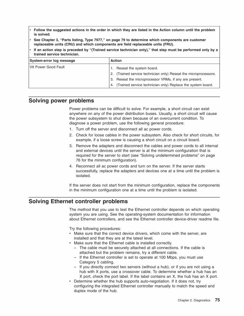
v Follow the suggested actions in the order in which they are listed in the Action column until the problem
is solved.
v See Chapter 3, “Parts listing, Type 7977,” on page 79 to determine which components are customer
replaceable units (CRU) and which components are field replaceable units (FRU).
v If an action step is preceded by “(Trained service technician only),” that step must be performed only by a
trained service technician.
System-error log message Action
Vtt Power Good Fault 1. Reseat the system board.
2. (Trained service technician only) Reseat the microprocessors.
3. Reseat the microprocessor VRMs, if any are present.
4. (Trained service technician only) Replace the system board.
Solving power problems
Power problems can be difficult to solve. For example, a short circuit can exist
anywhere on any of the power distribution buses. Usually, a short circuit will cause
the power subsystem to shut down because of an overcurrent condition. To
diagnose a power problem, use the following general procedure:
1. Turn off the server and disconnect all ac power cords.
2. Check for loose cables in the power subsystem. Also check for short circuits, for
example, if a loose screw is causing a short circuit on a circuit board.
3. Remove the adapters and disconnect the cables and power cords to all internal
and external devices until the server is at the minimum configuration that is
required for the server to start (see “Solving undetermined problems” on page
76 for the minimum configuration).
4. Reconnect all ac power cords and turn on the server. If the server starts
successfully, replace the adapters and devices one at a time until the problem is
isolated.
If the server does not start from the minimum configuration, replace the components
in the minimum configuration one at a time until the problem is isolated.
Solving Ethernet controller problems
The method that you use to test the Ethernet controller depends on which operating
system you are using. See the operating-system documentation for information
about Ethernet controllers, and see the Ethernet controller device-driver readme file.
Try the following procedures:
v Make sure that the correct device drivers, which come with the server, are
installed and that they are at the latest level.
v Make sure that the Ethernet cable is installed correctly.
– The cable must be securely attached at all connections. If the cable is
attached but the problem remains, try a different cable.
– If the Ethernet controller is set to operate at 100 Mbps, you must use
Category 5 cabling.
– If you directly connect two servers (without a hub), or if you are not using a
hub with X ports, use a crossover cable. To determine whether a hub has an
X port, check the port label. If the label contains an X, the hub has an X port.v Determine whether the hub supports auto-negotiation. If it does not, try
configuring the integrated Ethernet controller manually to match the speed and
duplex mode of the hub.
Chapter 2. Diagnostics 75
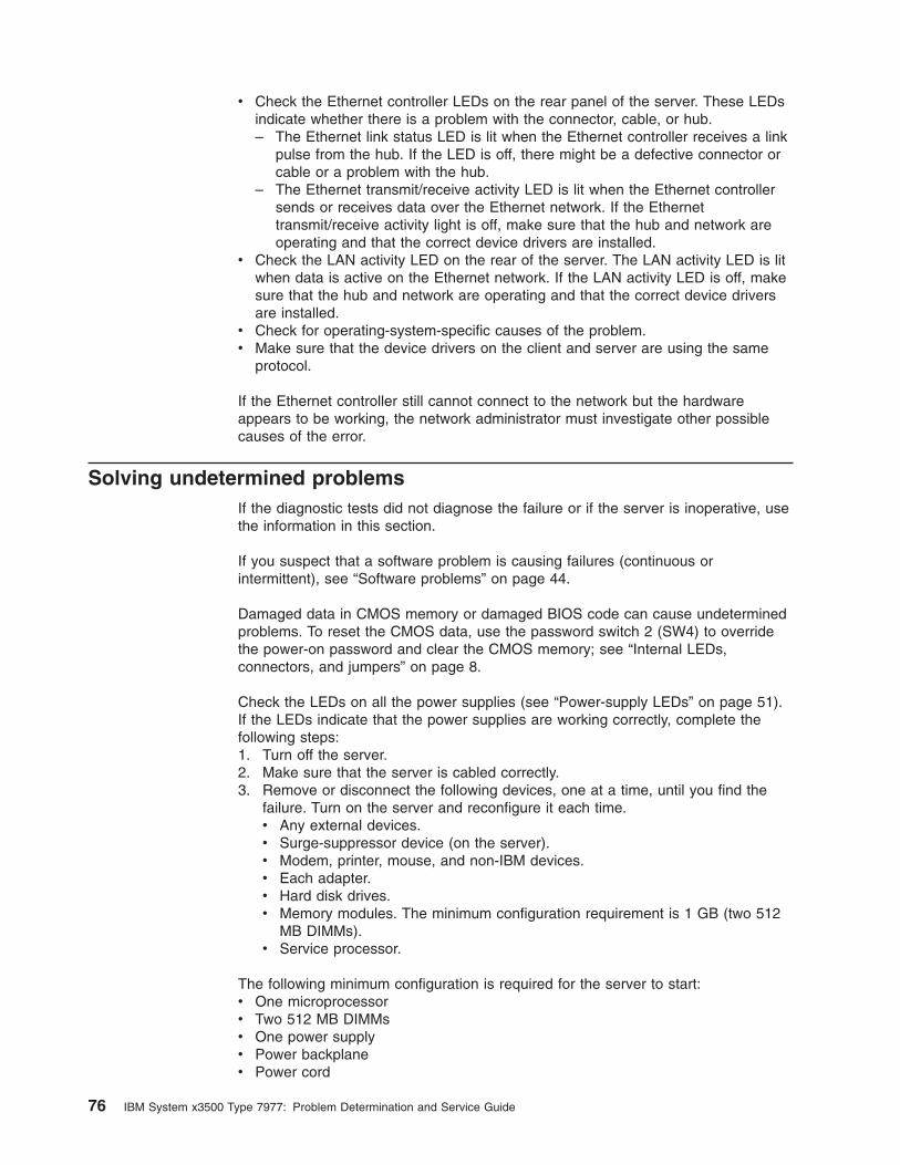
v Check the Ethernet controller LEDs on the rear panel of the server. These LEDs
indicate whether there is a problem with the connector, cable, or hub.
– The Ethernet link status LED is lit when the Ethernet controller receives a link
pulse from the hub. If the LED is off, there might be a defective connector or
cable or a problem with the hub.
– The Ethernet transmit/receive activity LED is lit when the Ethernet controller
sends or receives data over the Ethernet network. If the Ethernet
transmit/receive activity light is off, make sure that the hub and network are
operating and that the correct device drivers are installed.v Check the LAN activity LED on the rear of the server. The LAN activity LED is lit
when data is active on the Ethernet network. If the LAN activity LED is off, make
sure that the hub and network are operating and that the correct device drivers
are installed.
v Check for operating-system-specific causes of the problem.
v Make sure that the device drivers on the client and server are using the same
protocol.
If the Ethernet controller still cannot connect to the network but the hardware
appears to be working, the network administrator must investigate other possible
causes of the error.
Solving undetermined problems
If the diagnostic tests did not diagnose the failure or if the server is inoperative, use
the information in this section.
If you suspect that a software problem is causing failures (continuous or
intermittent), see “Software problems” on page 44.
Damaged data in CMOS memory or damaged BIOS code can cause undetermined
problems. To reset the CMOS data, use the password switch 2 (SW4) to override
the power-on password and clear the CMOS memory; see “Internal LEDs,
connectors, and jumpers” on page 8.
Check the LEDs on all the power supplies (see “Power-supply LEDs” on page 51).
If the LEDs indicate that the power supplies are working correctly, complete the
following steps:
1. Turn off the server.
2. Make sure that the server is cabled correctly.
3. Remove or disconnect the following devices, one at a time, until you find the
failure. Turn on the server and reconfigure it each time.
v Any external devices.
v Surge-suppressor device (on the server).
v Modem, printer, mouse, and non-IBM devices.
v Each adapter.
v Hard disk drives.
v Memory modules. The minimum configuration requirement is 1 GB (two 512
MB DIMMs).
v Service processor.
The following minimum configuration is required for the server to start:
v One microprocessor
v Two 512 MB DIMMs
v One power supply
v Power backplane
v Power cord
76 IBM System x3500 Type 7977: Problem Determination and Service Guide
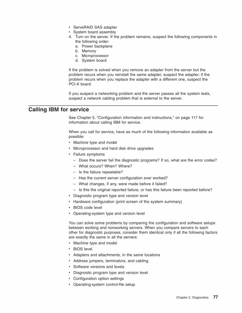
v ServeRAID SAS adapter
v System board assembly4. Turn on the server. If the problem remains, suspect the following components in
the following order:
a. Power backplane
b. Memory
c. Microprocessor
d. System board
If the problem is solved when you remove an adapter from the server but the
problem recurs when you reinstall the same adapter, suspect the adapter; if the
problem recurs when you replace the adapter with a different one, suspect the
PCI-X board.
If you suspect a networking problem and the server passes all the system tests,
suspect a network cabling problem that is external to the server.
Calling IBM for service
See Chapter 5, “Configuration information and instructions,” on page 117 for
information about calling IBM for service.
When you call for service, have as much of the following information available as
possible:
v Machine type and model
v Microprocessor and hard disk drive upgrades
v Failure symptoms
– Does the server fail the diagnostic programs? If so, what are the error codes?
– What occurs? When? Where?
– Is the failure repeatable?
– Has the current server configuration ever worked?
– What changes, if any, were made before it failed?
– Is this the original reported failure, or has this failure been reported before?
v Diagnostic program type and version level
v Hardware configuration (print screen of the system summary)
v BIOS code level
v Operating-system type and version level
You can solve some problems by comparing the configuration and software setups
between working and nonworking servers. When you compare servers to each
other for diagnostic purposes, consider them identical only if all the following factors
are exactly the same in all the servers:
v Machine type and model
v BIOS level
v Adapters and attachments, in the same locations
v Address jumpers, terminators, and cabling
v Software versions and levels
v Diagnostic program type and version level
v Configuration option settings
v Operating-system control-file setup
Chapter 2. Diagnostics 77

78 IBM System x3500 Type 7977: Problem Determination and Service Guide
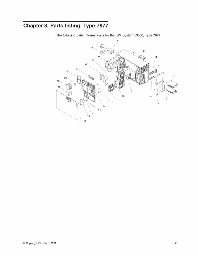
Chapter 3. Parts listing, Type 7977
The following parts information is for the IBM System x3500, Type 7977.
7
2
4
9
810
11
1
2524
22
23
6
5
12
14
15
18
19
13
20
16
17
21
3
26
© Copyright IBM Corp. 2007 79
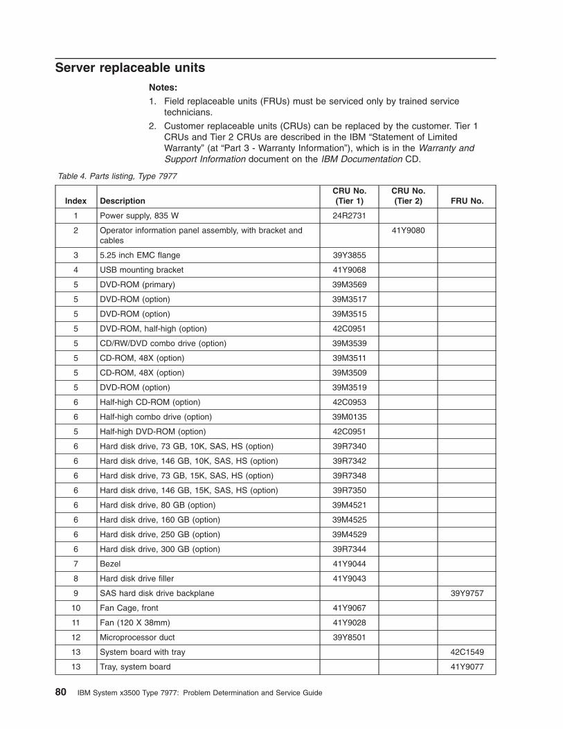
Server replaceable units
Notes:
1. Field replaceable units (FRUs) must be serviced only by trained service
technicians.
2. Customer replaceable units (CRUs) can be replaced by the customer. Tier 1
CRUs and Tier 2 CRUs are described in the IBM “Statement of Limited
Warranty” (at “Part 3 - Warranty Information”), which is in the Warranty and
Support Information document on the IBM Documentation CD.
Table 4. Parts listing, Type 7977
Index Description
CRU No.
(Tier 1)
CRU No.
(Tier 2) FRU No.
1 Power supply, 835 W 24R2731
2 Operator information panel assembly, with bracket and
cables
41Y9080
3 5.25 inch EMC flange 39Y3855
4 USB mounting bracket 41Y9068
5 DVD-ROM (primary) 39M3569
5 DVD-ROM (option) 39M3517
5 DVD-ROM (option) 39M3515
5 DVD-ROM, half-high (option) 42C0951
5 CD/RW/DVD combo drive (option) 39M3539
5 CD-ROM, 48X (option) 39M3511
5 CD-ROM, 48X (option) 39M3509
5 DVD-ROM (option) 39M3519
6 Half-high CD-ROM (option) 42C0953
6 Half-high combo drive (option) 39M0135
5 Half-high DVD-ROM (option) 42C0951
6 Hard disk drive, 73 GB, 10K, SAS, HS (option) 39R7340
6 Hard disk drive, 146 GB, 10K, SAS, HS (option) 39R7342
6 Hard disk drive, 73 GB, 15K, SAS, HS (option) 39R7348
6 Hard disk drive, 146 GB, 15K, SAS, HS (option) 39R7350
6 Hard disk drive, 80 GB (option) 39M4521
6 Hard disk drive, 160 GB (option) 39M4525
6 Hard disk drive, 250 GB (option) 39M4529
6 Hard disk drive, 300 GB (option) 39R7344
7 Bezel 41Y9044
8 Hard disk drive filler 41Y9043
9 SAS hard disk drive backplane 39Y9757
10 Fan Cage, front 41Y9067
11 Fan (120 X 38mm) 41Y9028
12 Microprocessor duct 39Y8501
13 System board with tray 42C1549
13 Tray, system board 41Y9077
80 IBM System x3500 Type 7977: Problem Determination and Service Guide
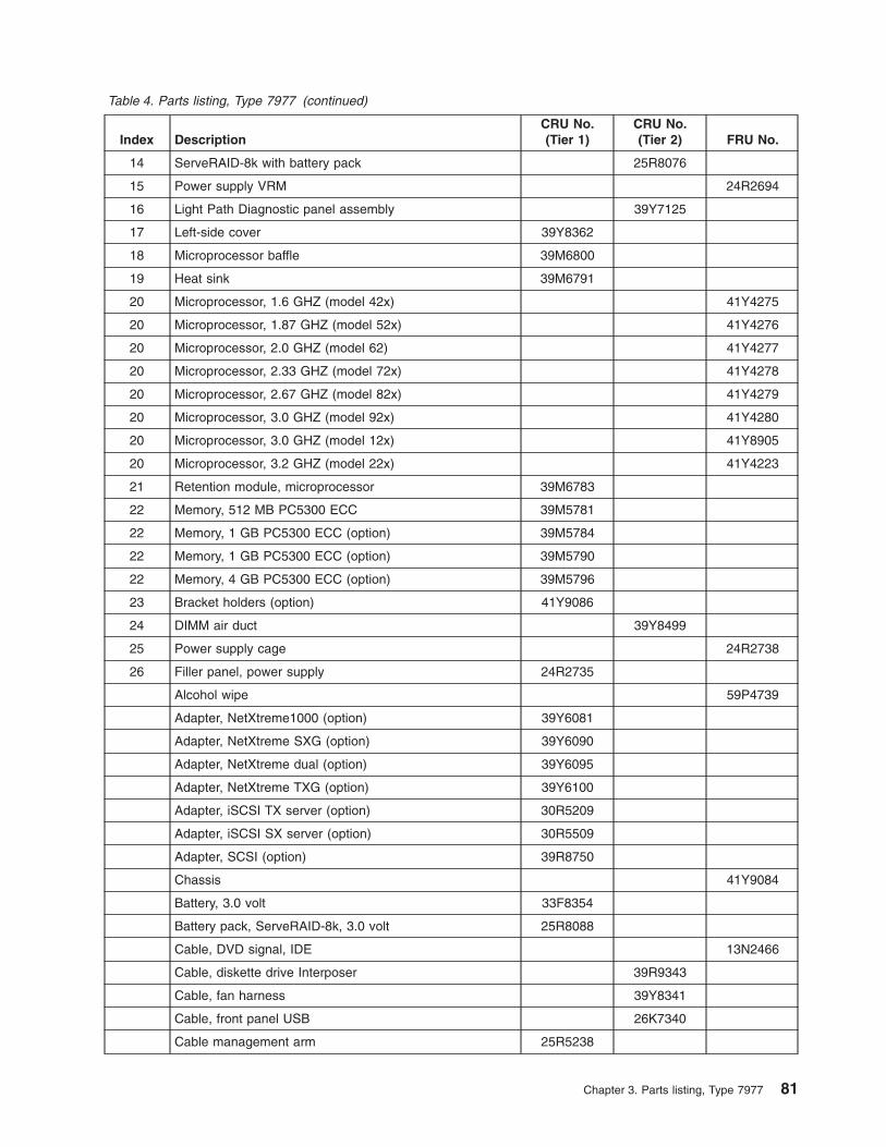
Table 4. Parts listing, Type 7977 (continued)
Index Description
CRU No.
(Tier 1)
CRU No.
(Tier 2) FRU No.
14 ServeRAID-8k with battery pack 25R8076
15 Power supply VRM 24R2694
16 Light Path Diagnostic panel assembly 39Y7125
17 Left-side cover 39Y8362
18 Microprocessor baffle 39M6800
19 Heat sink 39M6791
20 Microprocessor, 1.6 GHZ (model 42x) 41Y4275
20 Microprocessor, 1.87 GHZ (model 52x) 41Y4276
20 Microprocessor, 2.0 GHZ (model 62) 41Y4277
20 Microprocessor, 2.33 GHZ (model 72x) 41Y4278
20 Microprocessor, 2.67 GHZ (model 82x) 41Y4279
20 Microprocessor, 3.0 GHZ (model 92x) 41Y4280
20 Microprocessor, 3.0 GHZ (model 12x) 41Y8905
20 Microprocessor, 3.2 GHZ (model 22x) 41Y4223
21 Retention module, microprocessor 39M6783
22 Memory, 512 MB PC5300 ECC 39M5781
22 Memory, 1 GB PC5300 ECC (option) 39M5784
22 Memory, 1 GB PC5300 ECC (option) 39M5790
22 Memory, 4 GB PC5300 ECC (option) 39M5796
23 Bracket holders (option) 41Y9086
24 DIMM air duct 39Y8499
25 Power supply cage 24R2738
26 Filler panel, power supply 24R2735
Alcohol wipe 59P4739
Adapter, NetXtreme1000 (option) 39Y6081
Adapter, NetXtreme SXG (option) 39Y6090
Adapter, NetXtreme dual (option) 39Y6095
Adapter, NetXtreme TXG (option) 39Y6100
Adapter, iSCSI TX server (option) 30R5209
Adapter, iSCSI SX server (option) 30R5509
Adapter, SCSI (option) 39R8750
Chassis 41Y9084
Battery, 3.0 volt 33F8354
Battery pack, ServeRAID-8k, 3.0 volt 25R8088
Cable, DVD signal, IDE 13N2466
Cable, diskette drive Interposer 39R9343
Cable, fan harness 39Y8341
Cable, front panel USB 26K7340
Cable management arm 25R5238
Chapter 3. Parts listing, Type 7977 81
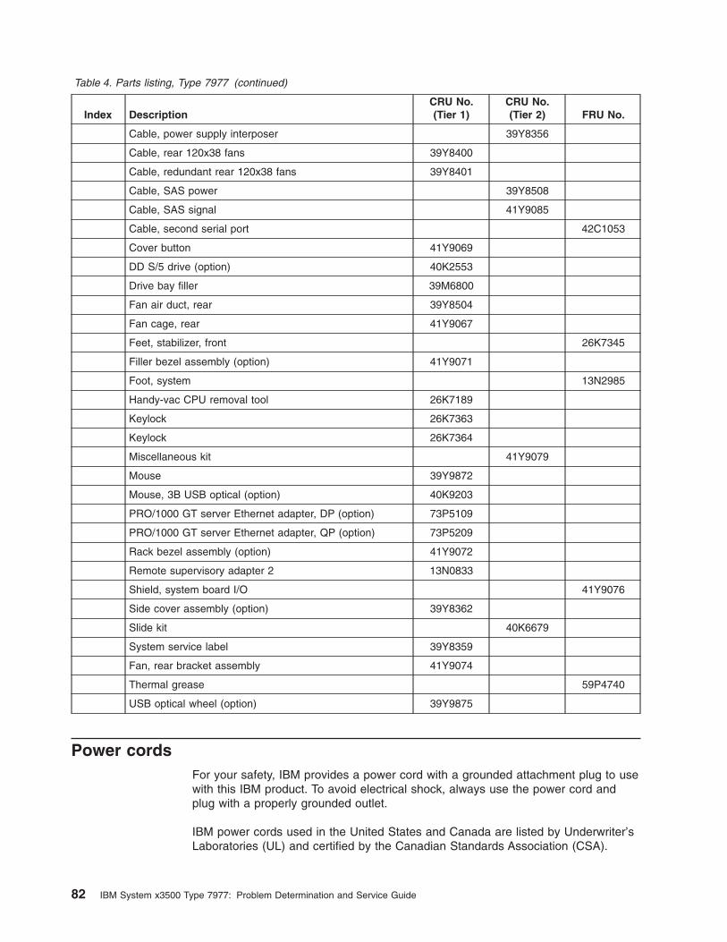
Table 4. Parts listing, Type 7977 (continued)
Index Description
CRU No.
(Tier 1)
CRU No.
(Tier 2) FRU No.
Cable, power supply interposer 39Y8356
Cable, rear 120x38 fans 39Y8400
Cable, redundant rear 120x38 fans 39Y8401
Cable, SAS power 39Y8508
Cable, SAS signal 41Y9085
Cable, second serial port 42C1053
Cover button 41Y9069
DD S/5 drive (option) 40K2553
Drive bay filler 39M6800
Fan air duct, rear 39Y8504
Fan cage, rear 41Y9067
Feet, stabilizer, front 26K7345
Filler bezel assembly (option) 41Y9071
Foot, system 13N2985
Handy-vac CPU removal tool 26K7189
Keylock 26K7363
Keylock 26K7364
Miscellaneous kit 41Y9079
Mouse 39Y9872
Mouse, 3B USB optical (option) 40K9203
PRO/1000 GT server Ethernet adapter, DP (option) 73P5109
PRO/1000 GT server Ethernet adapter, QP (option) 73P5209
Rack bezel assembly (option) 41Y9072
Remote supervisory adapter 2 13N0833
Shield, system board I/O 41Y9076
Side cover assembly (option) 39Y8362
Slide kit 40K6679
System service label 39Y8359
Fan, rear bracket assembly 41Y9074
Thermal grease 59P4740
USB optical wheel (option) 39Y9875
Power cords
For your safety, IBM provides a power cord with a grounded attachment plug to use
with this IBM product. To avoid electrical shock, always use the power cord and
plug with a properly grounded outlet.
IBM power cords used in the United States and Canada are listed by Underwriter’s
Laboratories (UL) and certified by the Canadian Standards Association (CSA).
82 IBM System x3500 Type 7977: Problem Determination and Service Guide
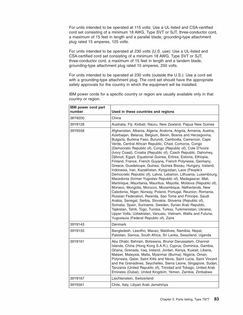
For units intended to be operated at 115 volts: Use a UL-listed and CSA-certified
cord set consisting of a minimum 18 AWG, Type SVT or SJT, three-conductor cord,
a maximum of 15 feet in length and a parallel blade, grounding-type attachment
plug rated 15 amperes, 125 volts.
For units intended to be operated at 230 volts (U.S. use): Use a UL-listed and
CSA-certified cord set consisting of a minimum 18 AWG, Type SVT or SJT,
three-conductor cord, a maximum of 15 feet in length and a tandem blade,
grounding-type attachment plug rated 15 amperes, 250 volts.
For units intended to be operated at 230 volts (outside the U.S.): Use a cord set
with a grounding-type attachment plug. The cord set should have the appropriate
safety approvals for the country in which the equipment will be installed.
IBM power cords for a specific country or region are usually available only in that
country or region.
IBM power cord part
number Used in these countries and regions
38Y8200 China
39Y8128 Australia, Fiji, Kiribati, Nauru, New Zealand, Papua New Guinea
39Y6558 Afghanistan, Albania, Algeria, Andorra, Angola, Armenia, Austria,
Azerbaijan, Belarus, Belgium, Benin, Bosnia and Herzegovina,
Bulgaria, Burkina Faso, Burundi, Cambodia, Cameroon, Cape
Verde, Central African Republic, Chad, Comoros, Congo
(Democratic Republic of), Congo (Republic of), Cote D’Ivoire
(Ivory Coast), Croatia (Republic of), Czech Republic, Dahomey,
Djibouti, Egypt, Equatorial Guinea, Eritrea, Estonia, Ethiopia,
Finland, France, French Guyana, French Polynesia, Germany,
Greece, Guadeloupe, Guinea, Guinea Bissau, Hungary, Iceland,
Indonesia, Iran, Kazakhstan, Kyrgyzstan, Laos (People’s
Democratic Republic of), Latvia, Lebanon, Lithuania, Luxembourg,
Macedonia (former Yugoslav Republic of), Madagascar, Mali,
Martinique, Mauritania, Mauritius, Mayotte, Moldova (Republic of),
Monaco, Mongolia, Morocco, Mozambique, Netherlands, New
Caledonia, Niger, Norway, Poland, Portugal, Reunion, Romania,
Russian Federation, Rwanda, Sao Tome and Principe, Saudi
Arabia, Senegal, Serbia, Slovakia, Slovenia (Republic of),
Somalia, Spain, Suriname, Sweden, Syrian Arab Republic,
Tajikistan, Tahiti, Togo, Tunisia, Turkey, Turkmenistan, Ukraine,
Upper Volta, Uzbekistan, Vanuatu, Vietnam, Wallis and Futuna,
Yugoslavia (Federal Republic of), Zaire
39Y8143 Denmark
39Y8155 Bangladesh, Lesotho, Macao, Maldives, Namibia, Nepal,
Pakistan, Samoa, South Africa, Sri Lanka, Swaziland, Uganda
39Y8161 Abu Dhabi, Bahrain, Botswana, Brunei Darussalam, Channel
Islands, China (Hong Kong S.A.R.), Cyprus, Dominica, Gambia,
Ghana, Grenada, Iraq, Ireland, Jordan, Kenya, Kuwait, Liberia,
Malawi, Malaysia, Malta, Myanmar (Burma), Nigeria, Oman,
Polynesia, Qatar, Saint Kitts and Nevis, Saint Lucia, Saint Vincent
and the Grenadines, Seychelles, Sierra Leone, Singapore, Sudan,
Tanzania (United Republic of), Trinidad and Tobago, United Arab
Emirates (Dubai), United Kingdom, Yemen, Zambia, Zimbabwe
39Y8167 Liechtenstein, Switzerland
39Y6561 Chile, Italy, Libyan Arab Jamahiriya
Chapter 3. Parts listing, Type 7977 83
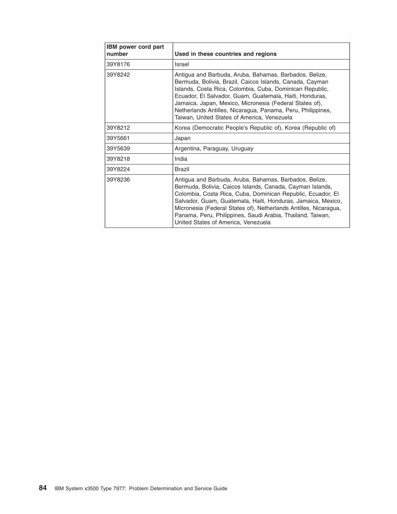
IBM power cord part
number Used in these countries and regions
39Y8176 Israel
39Y8242 Antigua and Barbuda, Aruba, Bahamas, Barbados, Belize,
Bermuda, Bolivia, Brazil, Caicos Islands, Canada, Cayman
Islands, Costa Rica, Colombia, Cuba, Dominican Republic,
Ecuador, El Salvador, Guam, Guatemala, Haiti, Honduras,
Jamaica, Japan, Mexico, Micronesia (Federal States of),
Netherlands Antilles, Nicaragua, Panama, Peru, Philippines,
Taiwan, United States of America, Venezuela
39Y8212 Korea (Democratic People’s Republic of), Korea (Republic of)
39Y5661 Japan
39Y5639 Argentina, Paraguay, Uruguay
39Y8218 India
39Y8224 Brazil
39Y8236 Antigua and Barbuda, Aruba, Bahamas, Barbados, Belize,
Bermuda, Bolivia, Caicos Islands, Canada, Cayman Islands,
Colombia, Costa Rica, Cuba, Dominican Republic, Ecuador, El
Salvador, Guam, Guatemala, Haiti, Honduras, Jamaica, Mexico,
Micronesia (Federal States of), Netherlands Antilles, Nicaragua,
Panama, Peru, Philippines, Saudi Arabia, Thailand, Taiwan,
United States of America, Venezuela
84 IBM System x3500 Type 7977: Problem Determination and Service Guide
Chapter 4. Removing and replacing server components
This chapter describes how to remove and replace certain server components. See
Chapter 3, “Parts listing, Type 7977,” on page 79 to determine whether the
component that is being replaced is a Tier 1 or Tier 2 customer-replaceable unit
(CRU), or a field-replaceable unit (FRU).
v Installation of Tier 1 CRUs is your responsibility. If IBM installs a Tier 1 CRU at
your request, you will be charged for the installation. You may install a Tier 2
CRU yourself or request IBM to install it, at no additional charge, under the type
of warranty service that is designated for your server.
v Installation of FRUs is intended only for trained service technicians who are
familiar with IBM System x products.
Installation guidelines
Before you install options, read the following information:
v Read the safety information that begins on page vii and the guidelines in
“Handling static-sensitive devices” on page 86. This information will help you
work safely.
v Observe good housekeeping in the area where you are working. Place removed
covers and other parts in a safe place.
v If you must start the server while the cover is removed, make sure that no one is
near the server and that no tools or other objects have been left inside the
server.
v Do not attempt to lift an object that you think is too heavy for you. If you have to
lift a heavy object, observe the following precautions:
– Make sure that you can stand safely without slipping.
– Distribute the weight of the object equally between your feet.
– Use a slow lifting force. Never move suddenly or twist when you lift a heavy
object.
– To avoid straining the muscles in your back, lift by standing or by pushing up
with your leg muscles.
v Make sure that you have an adequate number of properly grounded electrical
outlets for the server, monitor, and other devices.
v Back up all important data before you make changes to disk drives.
v Have a small flat-blade screwdriver available.
v You do not have to turn off the server to install or replace hot-swap power
supplies, hot-swap fans, or hot-plug Universal Serial Bus (USB) devices.
v Blue on a component indicates touch points, where you can grip the component
to remove it from or install it in the server, open or close a latch, and so on.
v Orange on a component or an orange label on or near a component indicates
that the component can be hot-swapped, which means that if the server and
operating system support hot-swap capability, you can remove or install the
component while the server is running. (Orange can also indicate touch points on
hot-swap components.) See the instructions for removing or installing a specific
hot-swap component for any additional procedures that you might have to
perform before you remove or install the component.
v When you are finished working on the server, reinstall all safety shields, guards,
labels, and ground wires.
v You can install a maximum of two IDE devices in the server.
© Copyright IBM Corp. 2007 85
v For a list of supported options for the server, see http://www.ibm.com/us/compact/.
System reliability guidelines
To help ensure proper cooling and system reliability, make sure that:
v Each of the drive bays has a drive or a filler panel and electromagnetic
compatibility (EMC) shield installed in it.
v If the server has redundant power, each of the power-supply bays has a power
supply installed in it.
v There is adequate space around the server to allow the server cooling system to
work properly. Leave approximately 50 mm (2.0 in.) of open space around the
front and rear of the server. Do not place objects in front of the fans. For proper
cooling and airflow, replace the server cover before turning on the server.
Operating the server for extended periods of time (more than 30 minutes) with
the server cover removed might damage server components.
v You have followed the cabling instructions that come with optional adapters.
v You have replaced a failed fan as soon as possible.
v You have replaced a hot-swap drive within 2 minutes of removal.
v You do not remove the air baffles or air ducts while the server is running.
Operating the server without the air baffle or air ducts might cause the
microprocessor to overheat.
v Microprocessor socket 2 always contains either a microprocessor baffle or a
microprocessor and heat sink.
Working inside the server with the power on
Attention: Static electricity that is released to internal server components when
the server is powered-on might cause the server to halt, which could result in the
loss of data. To avoid this potential problem, always use an electrostatic-discharge
wrist strap or other grounding system when working inside the server with the
power on.
The server supports hot-plug, hot-add, and hot-swap devices and is designed to
operate safely while it is turned on and the cover is removed. Follow these
guidelines when you work inside a server that is turned on:
v Avoid wearing loose-fitting clothing on your forearms. Button long-sleeved shirts
before working inside the server; do not wear cuff links while you are working
inside the server.
v Do not allow your necktie or scarf to hang inside the server.
v Remove jewelry, such as bracelets, necklaces, rings, and loose-fitting wrist
watches.
v Remove items from your shirt pocket, such as pens and pencils, that could fall
into the server as you lean over it.
v Avoid dropping any metallic objects, such as paper clips, hairpins, and screws,
into the server.
Handling static-sensitive devices
Attention: Static electricity can damage the server and other electronic devices.
To avoid damage, keep static-sensitive devices in their static-protective packages
until you are ready to install them.
86 IBM System x3500 Type 7977: Problem Determination and Service Guide
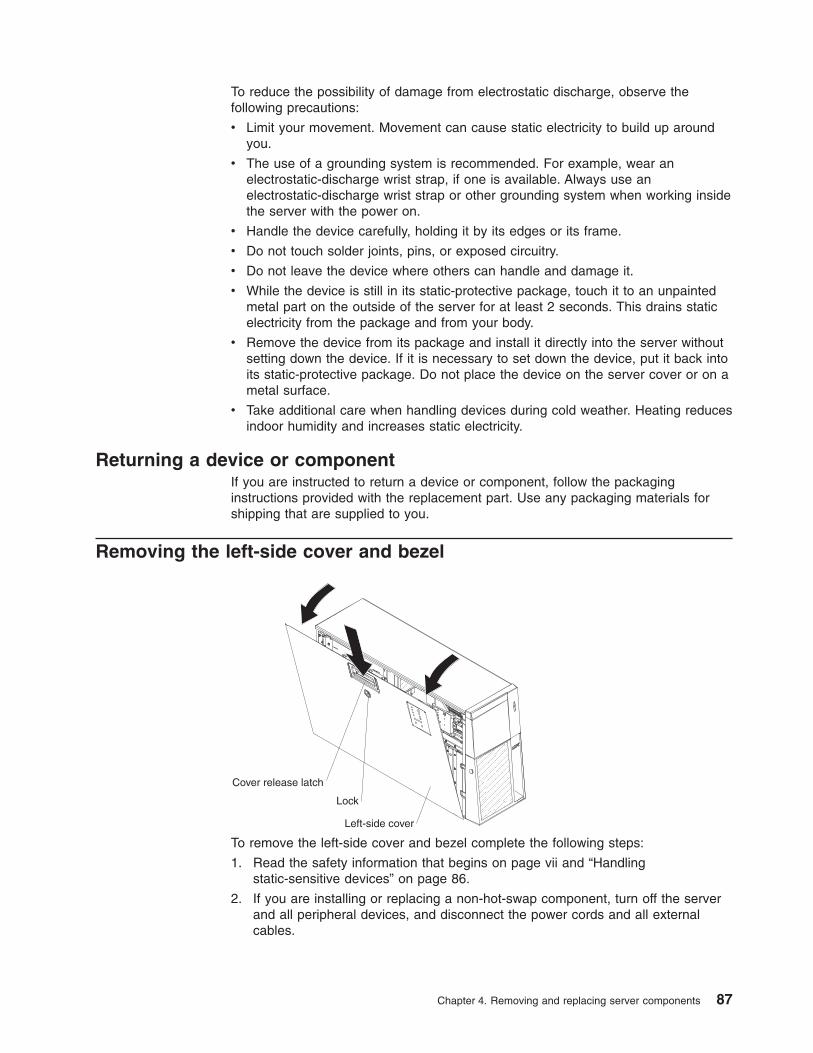
To reduce the possibility of damage from electrostatic discharge, observe the
following precautions:
v Limit your movement. Movement can cause static electricity to build up around
you.
v The use of a grounding system is recommended. For example, wear an
electrostatic-discharge wrist strap, if one is available. Always use an
electrostatic-discharge wrist strap or other grounding system when working inside
the server with the power on.
v Handle the device carefully, holding it by its edges or its frame.
v Do not touch solder joints, pins, or exposed circuitry.
v Do not leave the device where others can handle and damage it.
v While the device is still in its static-protective package, touch it to an unpainted
metal part on the outside of the server for at least 2 seconds. This drains static
electricity from the package and from your body.
v Remove the device from its package and install it directly into the server without
setting down the device. If it is necessary to set down the device, put it back into
its static-protective package. Do not place the device on the server cover or on a
metal surface.
v Take additional care when handling devices during cold weather. Heating reduces
indoor humidity and increases static electricity.
Returning a device or component
If you are instructed to return a device or component, follow the packaging
instructions provided with the replacement part. Use any packaging materials for
shipping that are supplied to you.
Removing the left-side cover and bezel
Left-side cover
Cover release latch
Lock
To remove the left-side cover and bezel complete the following steps:
1. Read the safety information that begins on page vii and “Handling
static-sensitive devices” on page 86.
2. If you are installing or replacing a non-hot-swap component, turn off the server
and all peripheral devices, and disconnect the power cords and all external
cables.
Chapter 4. Removing and replacing server components 87
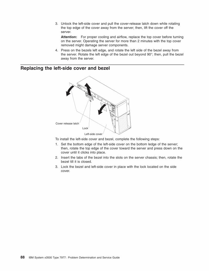
3. Unlock the left-side cover and pull the cover-release latch down while rotating
the top edge of the cover away from the server; then, lift the cover off the
server.
Attention: For proper cooling and airflow, replace the top cover before turning
on the server. Operating the server for more than 2 minutes with the top cover
removed might damage server components.
4. Press on the bezels left edge, and rotate the left side of the bezel away from
the server. Rotate the left edge of the bezel out beyond 90°; then, pull the bezel
away from the server.
Replacing the left-side cover and bezel
Left-side cover
Cover release latch
Lock
To install the left-side cover and bezel, complete the following steps:
1. Set the bottom edge of the left-side cover on the bottom ledge of the server;
then, rotate the top edge of the cover toward the server and press down on the
cover until it clicks into place.
2. Insert the tabs of the bezel into the slots on the server chassis; then, rotate the
bezel till it is closed.
3. Lock the bezel and left-side cover in place with the lock located on the side
cover.
88 IBM System x3500 Type 7977: Problem Determination and Service Guide
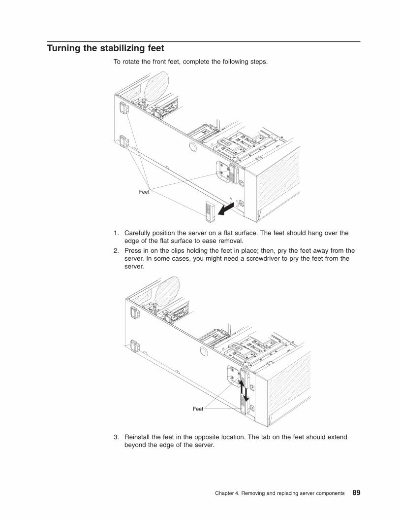
Turning the stabilizing feet
To rotate the front feet, complete the following steps.
Feet
1. Carefully position the server on a flat surface. The feet should hang over the
edge of the flat surface to ease removal.
2. Press in on the clips holding the feet in place; then, pry the feet away from the
server. In some cases, you might need a screwdriver to pry the feet from the
server.
Feet
3. Reinstall the feet in the opposite location. The tab on the feet should extend
beyond the edge of the server.
Chapter 4. Removing and replacing server components 89
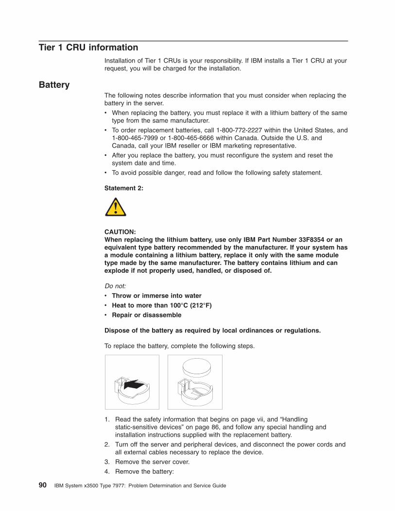
Tier 1 CRU information
Installation of Tier 1 CRUs is your responsibility. If IBM installs a Tier 1 CRU at your
request, you will be charged for the installation.
Battery
The following notes describe information that you must consider when replacing the
battery in the server.
v When replacing the battery, you must replace it with a lithium battery of the same
type from the same manufacturer.
v To order replacement batteries, call 1-800-772-2227 within the United States, and
1-800-465-7999 or 1-800-465-6666 within Canada. Outside the U.S. and
Canada, call your IBM reseller or IBM marketing representative.
v After you replace the battery, you must reconfigure the system and reset the
system date and time.
v To avoid possible danger, read and follow the following safety statement.
Statement 2:
CAUTION:
When replacing the lithium battery, use only IBM Part Number 33F8354 or an
equivalent type battery recommended by the manufacturer. If your system has
a module containing a lithium battery, replace it only with the same module
type made by the same manufacturer. The battery contains lithium and can
explode if not properly used, handled, or disposed of.
Do not:
v Throw or immerse into water
v Heat to more than 100°C (212°F)
v Repair or disassemble
Dispose of the battery as required by local ordinances or regulations.
To replace the battery, complete the following steps.
1. Read the safety information that begins on page vii, and “Handling
static-sensitive devices” on page 86, and follow any special handling and
installation instructions supplied with the replacement battery.
2. Turn off the server and peripheral devices, and disconnect the power cords and
all external cables necessary to replace the device.
3. Remove the server cover.
4. Remove the battery:
90 IBM System x3500 Type 7977: Problem Determination and Service Guide
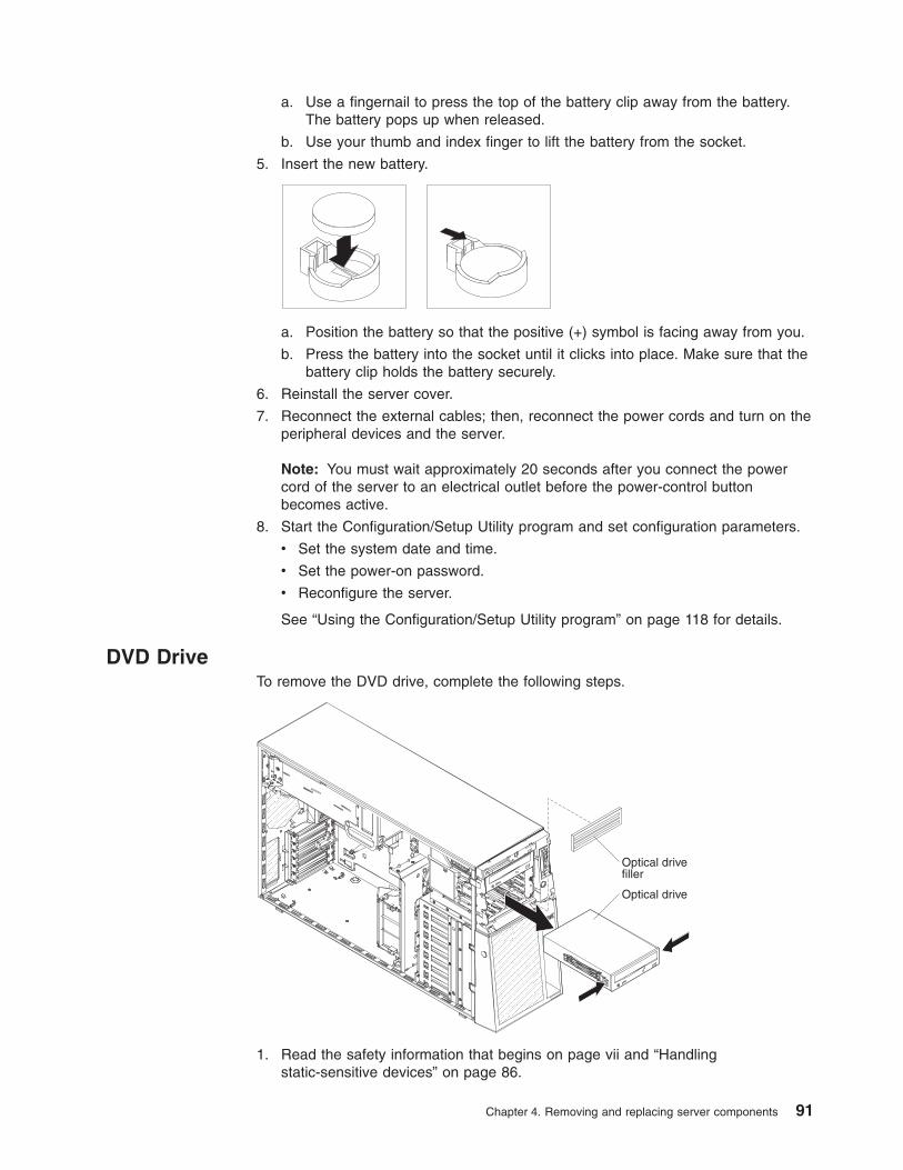
a. Use a fingernail to press the top of the battery clip away from the battery.
The battery pops up when released.
b. Use your thumb and index finger to lift the battery from the socket.
5. Insert the new battery.
a. Position the battery so that the positive (+) symbol is facing away from you.
b. Press the battery into the socket until it clicks into place. Make sure that the
battery clip holds the battery securely.
6. Reinstall the server cover.
7. Reconnect the external cables; then, reconnect the power cords and turn on the
peripheral devices and the server.
Note: You must wait approximately 20 seconds after you connect the power
cord of the server to an electrical outlet before the power-control button
becomes active.
8. Start the Configuration/Setup Utility program and set configuration parameters.
v Set the system date and time.
v Set the power-on password.
v Reconfigure the server.
See “Using the Configuration/Setup Utility program” on page 118 for details.
DVD Drive
To remove the DVD drive, complete the following steps.
Optical drive
Optical drivefiller
1. Read the safety information that begins on page vii and “Handling
static-sensitive devices” on page 86.
Chapter 4. Removing and replacing server components 91
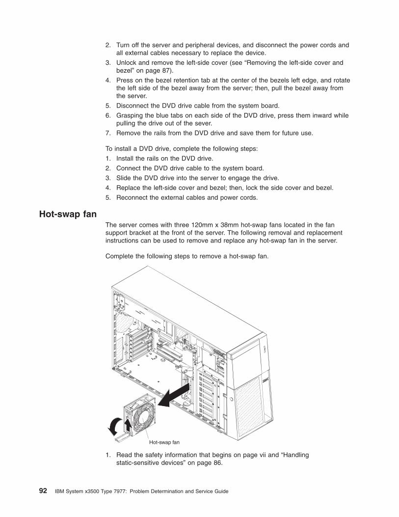
2. Turn off the server and peripheral devices, and disconnect the power cords and
all external cables necessary to replace the device.
3. Unlock and remove the left-side cover (see “Removing the left-side cover and
bezel” on page 87).
4. Press on the bezel retention tab at the center of the bezels left edge, and rotate
the left side of the bezel away from the server; then, pull the bezel away from
the server.
5. Disconnect the DVD drive cable from the system board.
6. Grasping the blue tabs on each side of the DVD drive, press them inward while
pulling the drive out of the sever.
7. Remove the rails from the DVD drive and save them for future use.
To install a DVD drive, complete the following steps:
1. Install the rails on the DVD drive.
2. Connect the DVD drive cable to the system board.
3. Slide the DVD drive into the server to engage the drive.
4. Replace the left-side cover and bezel; then, lock the side cover and bezel.
5. Reconnect the external cables and power cords.
Hot-swap fan
The server comes with three 120mm x 38mm hot-swap fans located in the fan
support bracket at the front of the server. The following removal and replacement
instructions can be used to remove and replace any hot-swap fan in the server.
Complete the following steps to remove a hot-swap fan.
Hot-swap fan
1. Read the safety information that begins on page vii and “Handling
static-sensitive devices” on page 86.
92 IBM System x3500 Type 7977: Problem Determination and Service Guide
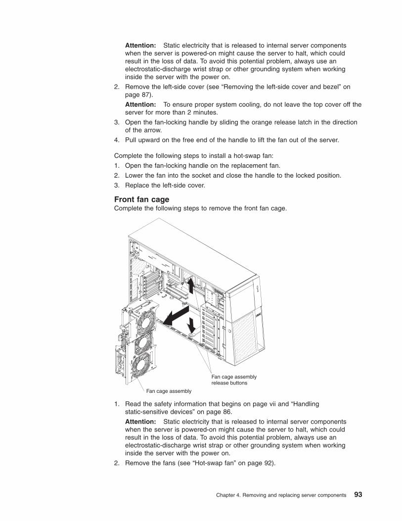
Attention: Static electricity that is released to internal server components
when the server is powered-on might cause the server to halt, which could
result in the loss of data. To avoid this potential problem, always use an
electrostatic-discharge wrist strap or other grounding system when working
inside the server with the power on.
2. Remove the left-side cover (see “Removing the left-side cover and bezel” on
page 87).
Attention: To ensure proper system cooling, do not leave the top cover off the
server for more than 2 minutes.
3. Open the fan-locking handle by sliding the orange release latch in the direction
of the arrow.
4. Pull upward on the free end of the handle to lift the fan out of the server.
Complete the following steps to install a hot-swap fan:
1. Open the fan-locking handle on the replacement fan.
2. Lower the fan into the socket and close the handle to the locked position.
3. Replace the left-side cover.
Front fan cage
Complete the following steps to remove the front fan cage.
Fan cage assembly
Fan cage assemblyrelease buttons
1. Read the safety information that begins on page vii and “Handling
static-sensitive devices” on page 86.
Attention: Static electricity that is released to internal server components
when the server is powered-on might cause the server to halt, which could
result in the loss of data. To avoid this potential problem, always use an
electrostatic-discharge wrist strap or other grounding system when working
inside the server with the power on.
2. Remove the fans (see “Hot-swap fan” on page 92).
Chapter 4. Removing and replacing server components 93
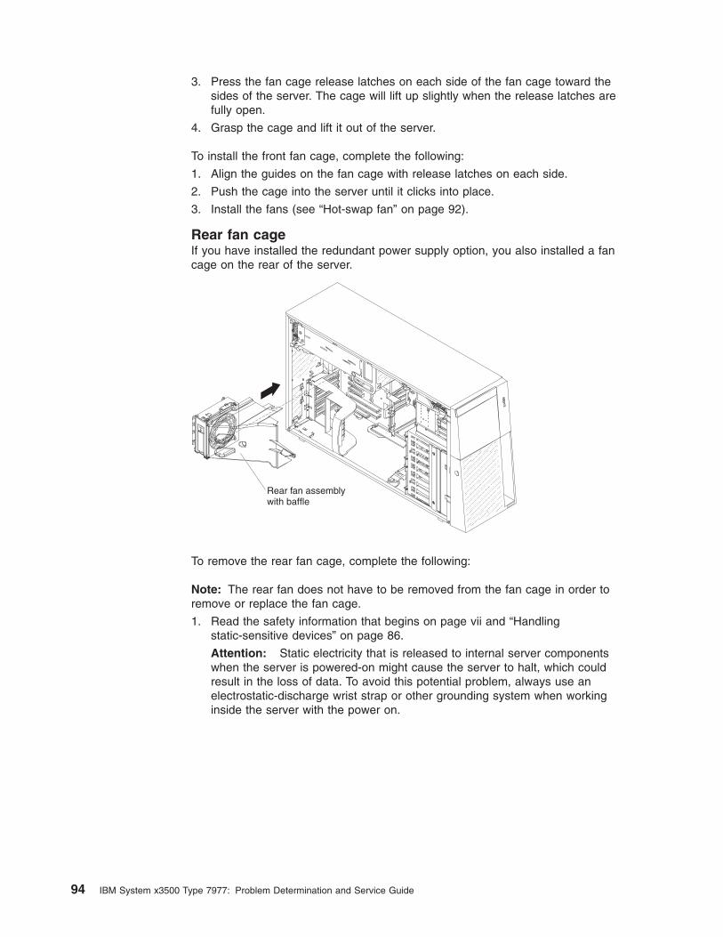
3. Press the fan cage release latches on each side of the fan cage toward the
sides of the server. The cage will lift up slightly when the release latches are
fully open.
4. Grasp the cage and lift it out of the server.
To install the front fan cage, complete the following:
1. Align the guides on the fan cage with release latches on each side.
2. Push the cage into the server until it clicks into place.
3. Install the fans (see “Hot-swap fan” on page 92).
Rear fan cage
If you have installed the redundant power supply option, you also installed a fan
cage on the rear of the server.
Rear fan assemblywith baffle
To remove the rear fan cage, complete the following:
Note: The rear fan does not have to be removed from the fan cage in order to
remove or replace the fan cage.
1. Read the safety information that begins on page vii and “Handling
static-sensitive devices” on page 86.
Attention: Static electricity that is released to internal server components
when the server is powered-on might cause the server to halt, which could
result in the loss of data. To avoid this potential problem, always use an
electrostatic-discharge wrist strap or other grounding system when working
inside the server with the power on.
94 IBM System x3500 Type 7977: Problem Determination and Service Guide
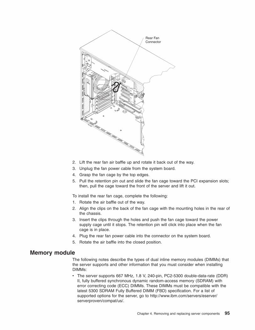
Rear FanConnector
2. Lift the rear fan air baffle up and rotate it back out of the way.
3. Unplug the fan power cable from the system board.
4. Grasp the fan cage by the top edges.
5. Pull the retention pin out and slide the fan cage toward the PCI expansion slots;
then, pull the cage toward the front of the server and lift it out.
To install the rear fan cage, complete the following:
1. Rotate the air baffle out of the way.
2. Align the clips on the back of the fan cage with the mounting holes in the rear of
the chassis.
3. Insert the clips through the holes and push the fan cage toward the power
supply cage until it stops. The retention pin will click into place when the fan
cage is in place.
4. Plug the rear fan power cable into the connector on the system board.
5. Rotate the air baffle into the closed position.
Memory module
The following notes describe the types of dual inline memory modules (DIMMs) that
the server supports and other information that you must consider when installing
DIMMs:
v The server supports 667 MHz, 1.8 V, 240-pin, PC2-5300 double-data-rate (DDR)
II, fully buffered synchronous dynamic random-access memory (SDRAM) with
error correcting code (ECC) DIMMs. These DIMMs must be compatible with the
latest 5300 SDRAM Fully Buffered DIMM (FBD) specification. For a list of
supported options for the server, go to http://www.ibm.com/servers/eserver/serverproven/compat/us/.
Chapter 4. Removing and replacing server components 95
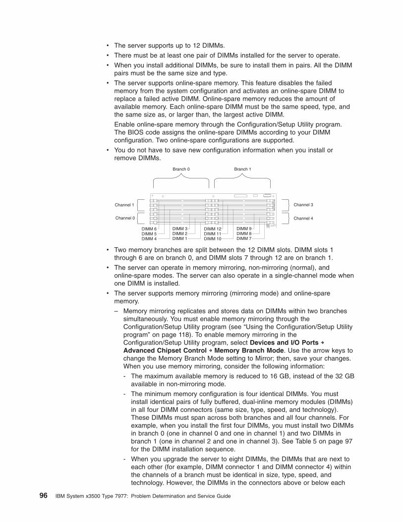
v The server supports up to 12 DIMMs.
v There must be at least one pair of DIMMs installed for the server to operate.
v When you install additional DIMMs, be sure to install them in pairs. All the DIMM
pairs must be the same size and type.
v The server supports online-spare memory. This feature disables the failed
memory from the system configuration and activates an online-spare DIMM to
replace a failed active DIMM. Online-spare memory reduces the amount of
available memory. Each online-spare DIMM must be the same speed, type, and
the same size as, or larger than, the largest active DIMM.
Enable online-spare memory through the Configuration/Setup Utility program.
The BIOS code assigns the online-spare DIMMs according to your DIMM
configuration. Two online-spare configurations are supported.
v You do not have to save new configuration information when you install or
remove DIMMs.
Branch 0 Branch 1
Channel 1
Channel 4
Channel 3
Channel 0
DIMM 6DIMM 5DIMM 4
DIMM 12DIMM 11DIMM 10
DIMM 3DIMM 2DIMM 1
DIMM 9DIMM 8DIMM 7
v Two memory branches are split between the 12 DIMM slots. DIMM slots 1
through 6 are on branch 0, and DIMM slots 7 through 12 are on branch 1.
v The server can operate in memory mirroring, non-mirroring (normal), and
online-spare modes. The server can also operate in a single-channel mode when
one DIMM is installed.
v The server supports memory mirroring (mirroring mode) and online-spare
memory.
– Memory mirroring replicates and stores data on DIMMs within two branches
simultaneously. You must enable memory mirroring through the
Configuration/Setup Utility program (see “Using the Configuration/Setup Utility
program” on page 118). To enable memory mirroring in the
Configuration/Setup Utility program, select Devices and I/O Ports →
Advanced Chipset Control → Memory Branch Mode. Use the arrow keys to
change the Memory Branch Mode setting to Mirror; then, save your changes.
When you use memory mirroring, consider the following information:
- The maximum available memory is reduced to 16 GB, instead of the 32 GB
available in non-mirroring mode.
- The minimum memory configuration is four identical DIMMs. You must
install identical pairs of fully buffered, dual-inline memory modules (DIMMs)
in all four DIMM connectors (same size, type, speed, and technology).
These DIMMs must span across both branches and all four channels. For
example, when you install the first four DIMMs, you must install two DIMMs
in branch 0 (one in channel 0 and one in channel 1) and two DIMMs in
branch 1 (one in channel 2 and one in channel 3). See Table 5 on page 97
for the DIMM installation sequence.
- When you upgrade the server to eight DIMMs, the DIMMs that are next to
each other (for example, DIMM connector 1 and DIMM connector 4) within
the channels of a branch must be identical in size, type, speed, and
technology. However, the DIMMs in the connectors above or below each
96 IBM System x3500 Type 7977: Problem Determination and Service Guide
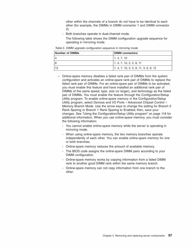
other within the channels of a branch do not have to be identical to each
other (for example, the DIMMs in DIMM connector 1 and DIMM connector
2).
- Both branches operate in dual-channel mode.
The following table shows the DIMM configuration upgrade sequence for
operating in mirroring mode.
Table 5. DIMM upgrade configuration sequence in mirroring mode
Number of DIMMs DIMM connectors
4 1, 4, 7, 10
8 1, 4, 7, 10, 2, 5, 8, 11
12 1, 4, 7, 10, 2, 5, 8, 11, 3, 6, 9, 12
– Online-spare memory disables a failed rank pair of DIMMs from the system
configuration and activates an online-spare rank pair of DIMMs to replace the
failed rank pair of DIMMs. For an online-spare pair of DIMMs to be activated,
you must enable this feature and have installed an additional rank pair of
DIMMs of the same speed, type, size (or larger), and technology as the failed
pair of DIMMs. You must enable the feature through the Configuration/Setup
Utility program. To enable online-spare memory in the Configuration/Setup
Utility program, select Devices and I/O Ports → Advanced Chipset Control →
Memory Branch Mode. Use the arrow keys to change the setting for Branch 0
Rank Sparing or Branch 1 Rank Sparing to Enabled; then, save your
changes. See “Using the Configuration/Setup Utility program” on page 118 for
additional information. When you use online-spare memory, you must consider
the following information:
- You cannot enable online-spare memory while the server is operating in
mirroring mode.
- When using online-spare memory, the two memory branches operate
independently of each other. You can enable online-spare memory for one
or both branches.
- Online-spare memory reduces the amount of available memory.
- The BIOS code assigns the online-spare DIMM pairs according to your
DIMM configuration.
- Online-spare memory works by copying information from a failed DIMM
rank to another good DIMM rank within the same memory branch.
- Online-spare memory can not copy information from one branch to the
other.
Chapter 4. Removing and replacing server components 97
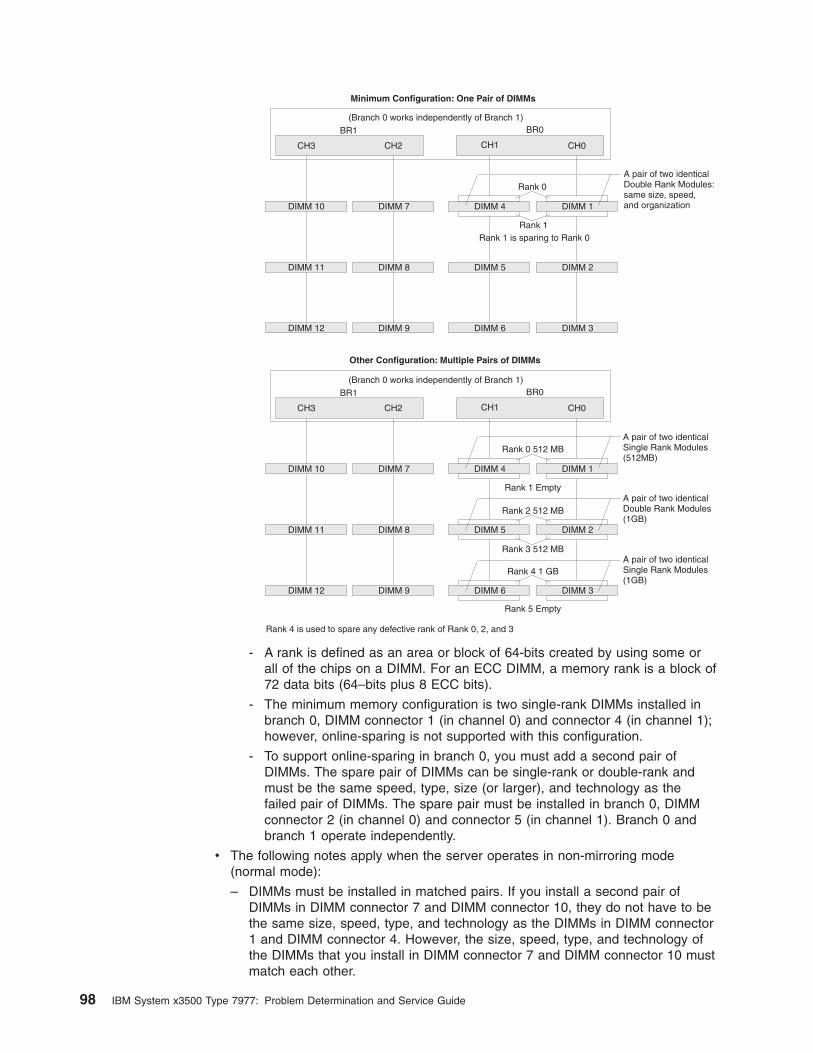
BR0
BR0
BR1
BR1
DIMM 7
DIMM 8
DIMM 9
CH2
DIMM 7
DIMM 8
DIMM 9
CH2
DIMM 10
DIMM 11
DIMM 12
CH3
DIMM 10
DIMM 11
DIMM 12
CH3
Rank 0
Rank 0 512 MB
Rank 4 1 GB
Rank 2 512 MB
Rank 1
Rank 1 Empty
Rank 5 Empty
Rank 3 512 MB
Minimum Configuration: One Pair of DIMMs
Other Configuration: Multiple Pairs of DIMMs
(Branch 0 works independently of Branch 1)
(Branch 0 works independently of Branch 1)
Rank 4 is used to spare any defective rank of Rank 0, 2, and 3
A pair of two identicalDouble Rank Modules:same size, speed,and organization
Rank 1 is sparing to Rank 0
DIMM 1
DIMM 1
DIMM 2
DIMM 2
DIMM 3
DIMM 3
CH0
CH0
DIMM 4
DIMM 4
DIMM 5
DIMM 5
DIMM 6
DIMM 6
CH1
CH1
A pair of two identicalSingle Rank Modules(512MB)
A pair of two identicalSingle Rank Modules(1GB)
A pair of two identicalDouble Rank Modules(1GB)
- A rank is defined as an area or block of 64-bits created by using some or
all of the chips on a DIMM. For an ECC DIMM, a memory rank is a block of
72 data bits (64–bits plus 8 ECC bits).
- The minimum memory configuration is two single-rank DIMMs installed in
branch 0, DIMM connector 1 (in channel 0) and connector 4 (in channel 1);
however, online-sparing is not supported with this configuration.
- To support online-sparing in branch 0, you must add a second pair of
DIMMs. The spare pair of DIMMs can be single-rank or double-rank and
must be the same speed, type, size (or larger), and technology as the
failed pair of DIMMs. The spare pair must be installed in branch 0, DIMM
connector 2 (in channel 0) and connector 5 (in channel 1). Branch 0 and
branch 1 operate independently.
v The following notes apply when the server operates in non-mirroring mode
(normal mode):
– DIMMs must be installed in matched pairs. If you install a second pair of
DIMMs in DIMM connector 7 and DIMM connector 10, they do not have to be
the same size, speed, type, and technology as the DIMMs in DIMM connector
1 and DIMM connector 4. However, the size, speed, type, and technology of
the DIMMs that you install in DIMM connector 7 and DIMM connector 10 must
match each other.
98 IBM System x3500 Type 7977: Problem Determination and Service Guide
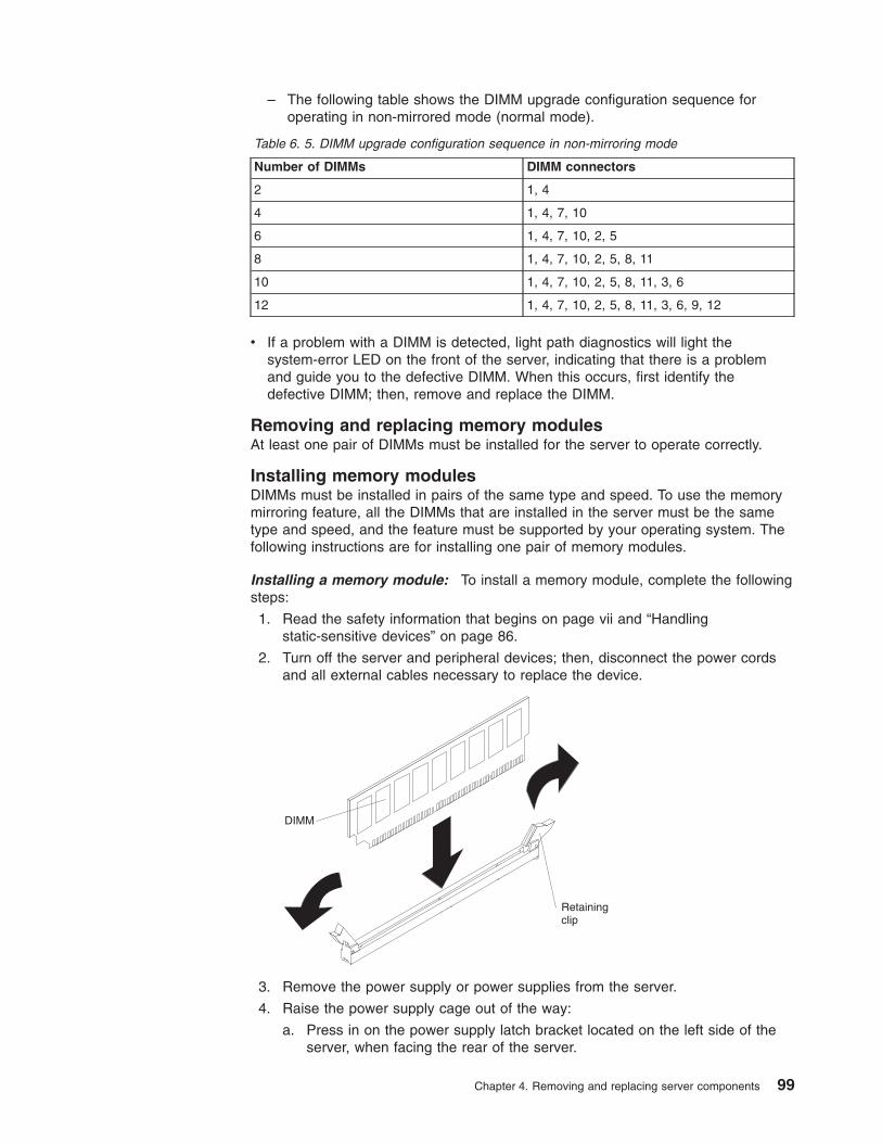
– The following table shows the DIMM upgrade configuration sequence for
operating in non-mirrored mode (normal mode).
Table 6. 5. DIMM upgrade configuration sequence in non-mirroring mode
Number of DIMMs DIMM connectors
2 1, 4
4 1, 4, 7, 10
6 1, 4, 7, 10, 2, 5
8 1, 4, 7, 10, 2, 5, 8, 11
10 1, 4, 7, 10, 2, 5, 8, 11, 3, 6
12 1, 4, 7, 10, 2, 5, 8, 11, 3, 6, 9, 12
v If a problem with a DIMM is detected, light path diagnostics will light the
system-error LED on the front of the server, indicating that there is a problem
and guide you to the defective DIMM. When this occurs, first identify the
defective DIMM; then, remove and replace the DIMM.
Removing and replacing memory modules
At least one pair of DIMMs must be installed for the server to operate correctly.
Installing memory modules
DIMMs must be installed in pairs of the same type and speed. To use the memory
mirroring feature, all the DIMMs that are installed in the server must be the same
type and speed, and the feature must be supported by your operating system. The
following instructions are for installing one pair of memory modules.
Installing a memory module: To install a memory module, complete the following
steps:
1. Read the safety information that begins on page vii and “Handling
static-sensitive devices” on page 86.
2. Turn off the server and peripheral devices; then, disconnect the power cords
and all external cables necessary to replace the device.
DIMM
Retainingclip
3. Remove the power supply or power supplies from the server.
4. Raise the power supply cage out of the way:
a. Press in on the power supply latch bracket located on the left side of the
server, when facing the rear of the server.
Chapter 4. Removing and replacing server components 99
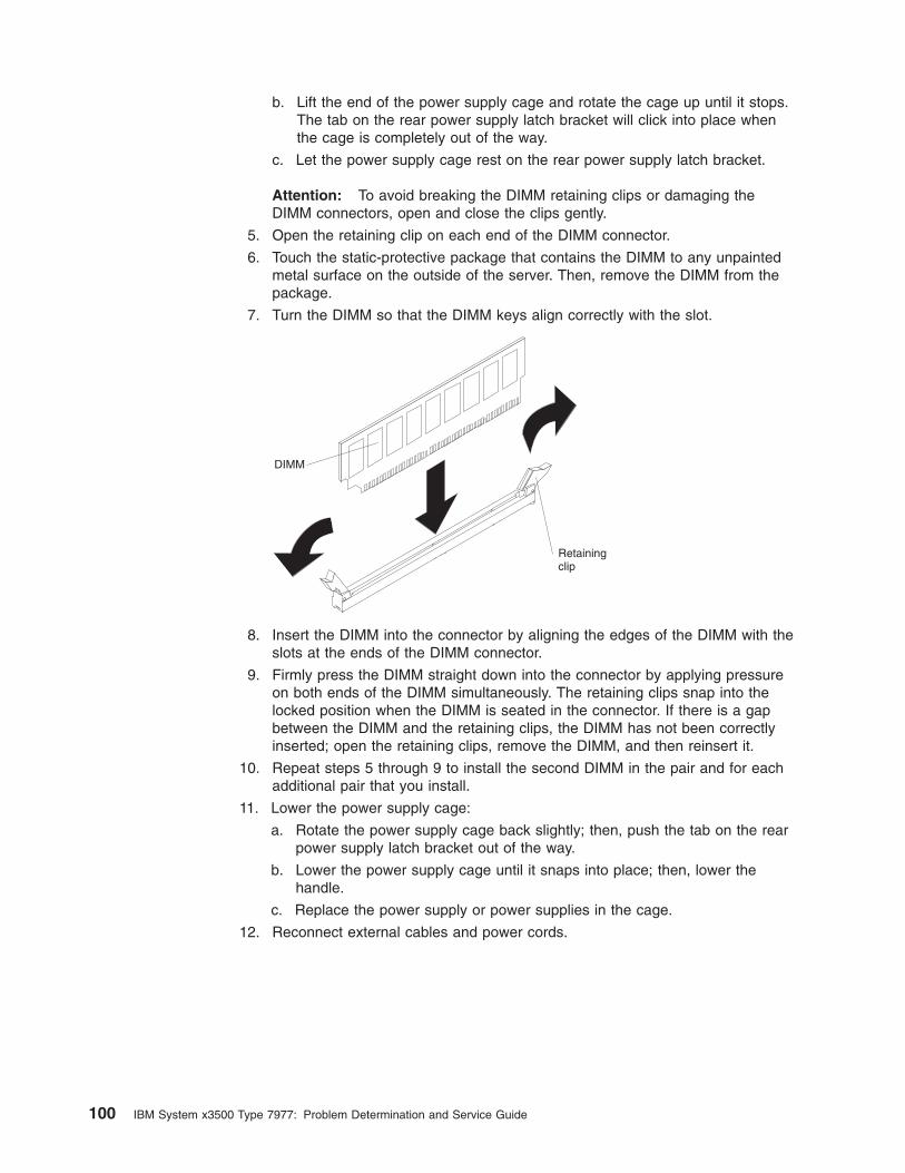
b. Lift the end of the power supply cage and rotate the cage up until it stops.
The tab on the rear power supply latch bracket will click into place when
the cage is completely out of the way.
c. Let the power supply cage rest on the rear power supply latch bracket.
Attention: To avoid breaking the DIMM retaining clips or damaging the
DIMM connectors, open and close the clips gently.
5. Open the retaining clip on each end of the DIMM connector.
6. Touch the static-protective package that contains the DIMM to any unpainted
metal surface on the outside of the server. Then, remove the DIMM from the
package.
7. Turn the DIMM so that the DIMM keys align correctly with the slot.
DIMM
Retainingclip
8. Insert the DIMM into the connector by aligning the edges of the DIMM with the
slots at the ends of the DIMM connector.
9. Firmly press the DIMM straight down into the connector by applying pressure
on both ends of the DIMM simultaneously. The retaining clips snap into the
locked position when the DIMM is seated in the connector. If there is a gap
between the DIMM and the retaining clips, the DIMM has not been correctly
inserted; open the retaining clips, remove the DIMM, and then reinsert it.
10. Repeat steps 5 through 9 to install the second DIMM in the pair and for each
additional pair that you install.
11. Lower the power supply cage:
a. Rotate the power supply cage back slightly; then, push the tab on the rear
power supply latch bracket out of the way.
b. Lower the power supply cage until it snaps into place; then, lower the
handle.
c. Replace the power supply or power supplies in the cage.
12. Reconnect external cables and power cords.
100 IBM System x3500 Type 7977: Problem Determination and Service Guide
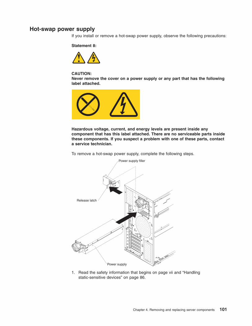
Hot-swap power supply
If you install or remove a hot-swap power supply, observe the following precautions:
Statement 8:
CAUTION:
Never remove the cover on a power supply or any part that has the following
label attached.
Hazardous voltage, current, and energy levels are present inside any
component that has this label attached. There are no serviceable parts inside
these components. If you suspect a problem with one of these parts, contact
a service technician.
To remove a hot-swap power supply, complete the following steps.
Power supply filler
Release latch
Power supply
1. Read the safety information that begins on page vii and “Handling
static-sensitive devices” on page 86.
Chapter 4. Removing and replacing server components 101
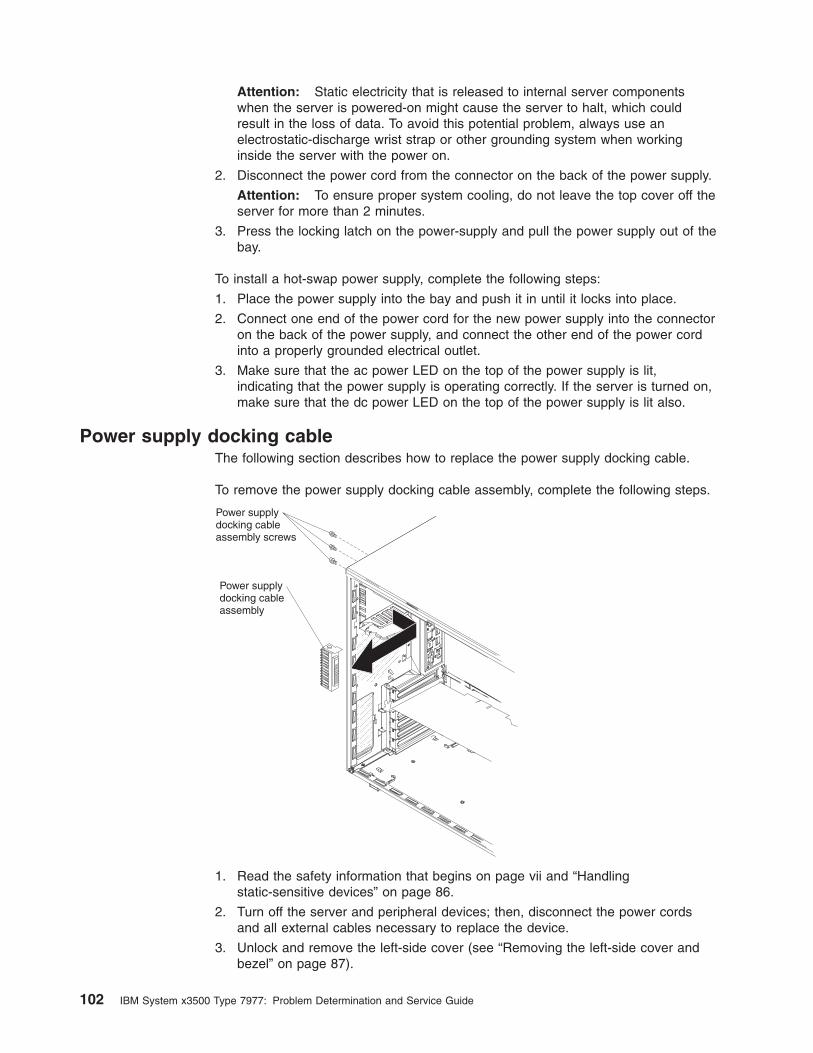
Attention: Static electricity that is released to internal server components
when the server is powered-on might cause the server to halt, which could
result in the loss of data. To avoid this potential problem, always use an
electrostatic-discharge wrist strap or other grounding system when working
inside the server with the power on.
2. Disconnect the power cord from the connector on the back of the power supply.
Attention: To ensure proper system cooling, do not leave the top cover off the
server for more than 2 minutes.
3. Press the locking latch on the power-supply and pull the power supply out of the
bay.
To install a hot-swap power supply, complete the following steps:
1. Place the power supply into the bay and push it in until it locks into place.
2. Connect one end of the power cord for the new power supply into the connector
on the back of the power supply, and connect the other end of the power cord
into a properly grounded electrical outlet.
3. Make sure that the ac power LED on the top of the power supply is lit,
indicating that the power supply is operating correctly. If the server is turned on,
make sure that the dc power LED on the top of the power supply is lit also.
Power supply docking cable
The following section describes how to replace the power supply docking cable.
To remove the power supply docking cable assembly, complete the following steps.
Power supplydocking cableassembly screws
Power supplydocking cableassembly
1. Read the safety information that begins on page vii and “Handling
static-sensitive devices” on page 86.
2. Turn off the server and peripheral devices; then, disconnect the power cords
and all external cables necessary to replace the device.
3. Unlock and remove the left-side cover (see “Removing the left-side cover and
bezel” on page 87).
102 IBM System x3500 Type 7977: Problem Determination and Service Guide
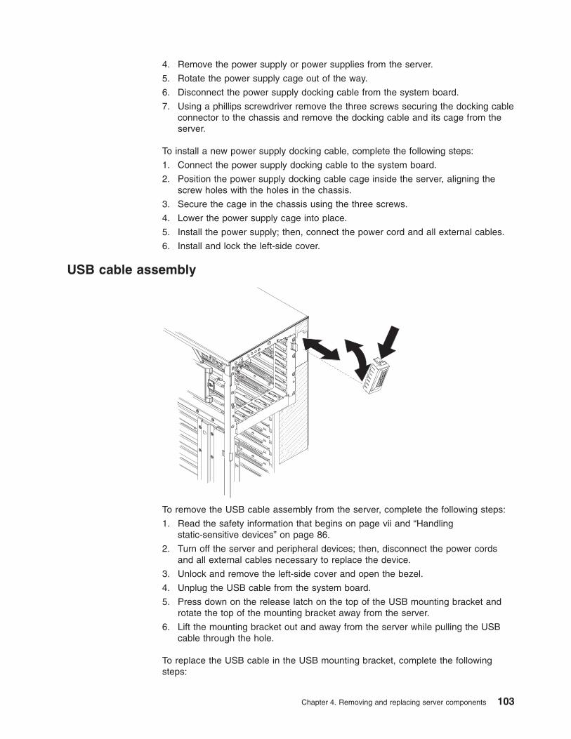
4. Remove the power supply or power supplies from the server.
5. Rotate the power supply cage out of the way.
6. Disconnect the power supply docking cable from the system board.
7. Using a phillips screwdriver remove the three screws securing the docking cable
connector to the chassis and remove the docking cable and its cage from the
server.
To install a new power supply docking cable, complete the following steps:
1. Connect the power supply docking cable to the system board.
2. Position the power supply docking cable cage inside the server, aligning the
screw holes with the holes in the chassis.
3. Secure the cage in the chassis using the three screws.
4. Lower the power supply cage into place.
5. Install the power supply; then, connect the power cord and all external cables.
6. Install and lock the left-side cover.
USB cable assembly
To remove the USB cable assembly from the server, complete the following steps:
1. Read the safety information that begins on page vii and “Handling
static-sensitive devices” on page 86.
2. Turn off the server and peripheral devices; then, disconnect the power cords
and all external cables necessary to replace the device.
3. Unlock and remove the left-side cover and open the bezel.
4. Unplug the USB cable from the system board.
5. Press down on the release latch on the top of the USB mounting bracket and
rotate the top of the mounting bracket away from the server.
6. Lift the mounting bracket out and away from the server while pulling the USB
cable through the hole.
To replace the USB cable in the USB mounting bracket, complete the following
steps:
Chapter 4. Removing and replacing server components 103
1. Complete steps 1 through 6 to remove the USB cable assembly from the
server; then, return here and continue with step 2.
2. Rotate the mounting bracket so that you are looking at the rear of the bracket;
then, squeeze the retaining clips on each side of the connector and remove the
cable from the mounting bracket.
3. Squeeze the retaining clips on each side of the USB cable connector and insert
the connector into the mounting bracket; then, release the retaining clips.
To install the USB cable assembly in the server, complete the following steps:
1. Feed the USB cable into the server through the opening in the front of the
server.
2. Position the bottom of the mounting bracket into the opening and rotate the top
of the bracket toward the server until it clicks into place.
3. Plug the USB cable into the USB connector on the system board. See
“System-board internal connectors and switches” on page 8 to locate the USB
connector on the system board.
104 IBM System x3500 Type 7977: Problem Determination and Service Guide
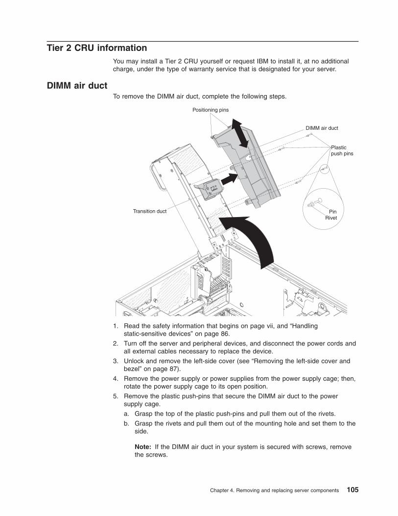
Tier 2 CRU information
You may install a Tier 2 CRU yourself or request IBM to install it, at no additional
charge, under the type of warranty service that is designated for your server.
DIMM air duct
To remove the DIMM air duct, complete the following steps.
Transition duct
DIMM air duct
Plasticpush pins
Positioning pins
RivetPin
1. Read the safety information that begins on page vii, and “Handling
static-sensitive devices” on page 86.
2. Turn off the server and peripheral devices, and disconnect the power cords and
all external cables necessary to replace the device.
3. Unlock and remove the left-side cover (see “Removing the left-side cover and
bezel” on page 87).
4. Remove the power supply or power supplies from the power supply cage; then,
rotate the power supply cage to its open position.
5. Remove the plastic push-pins that secure the DIMM air duct to the power
supply cage.
a. Grasp the top of the plastic push-pins and pull them out of the rivets.
b. Grasp the rivets and pull them out of the mounting hole and set them to the
side.
Note: If the DIMM air duct in your system is secured with screws, remove
the screws.
Chapter 4. Removing and replacing server components 105
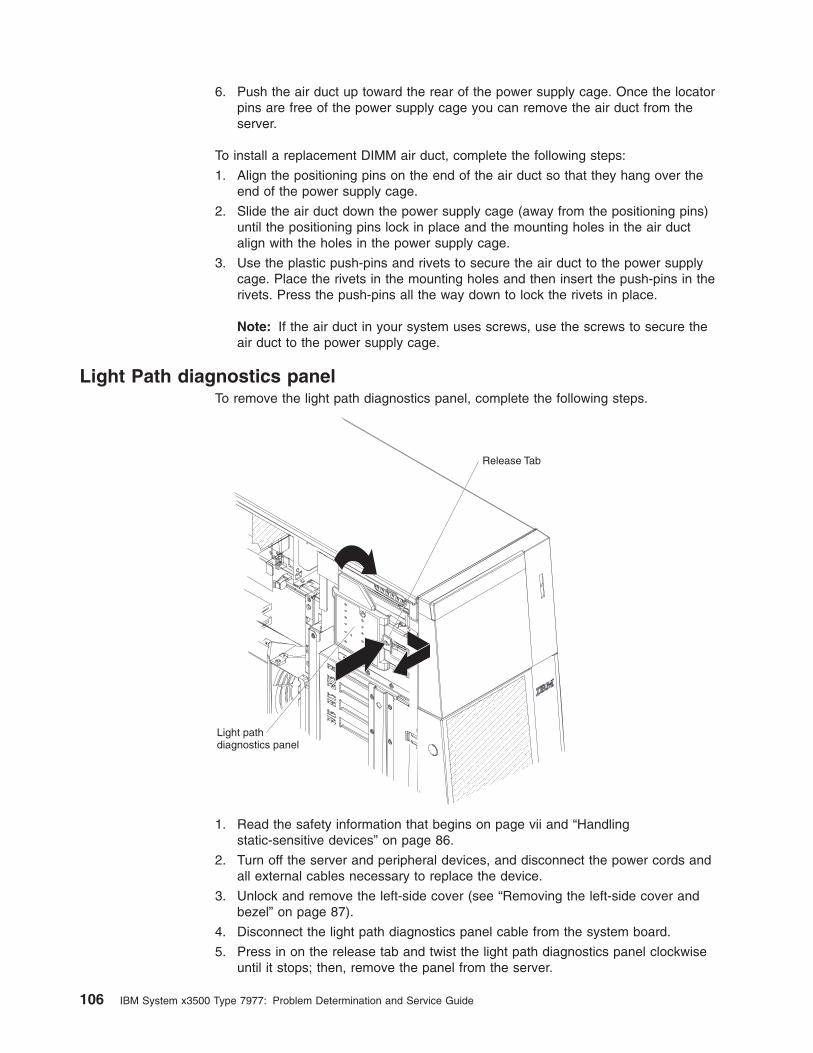
6. Push the air duct up toward the rear of the power supply cage. Once the locator
pins are free of the power supply cage you can remove the air duct from the
server.
To install a replacement DIMM air duct, complete the following steps:
1. Align the positioning pins on the end of the air duct so that they hang over the
end of the power supply cage.
2. Slide the air duct down the power supply cage (away from the positioning pins)
until the positioning pins lock in place and the mounting holes in the air duct
align with the holes in the power supply cage.
3. Use the plastic push-pins and rivets to secure the air duct to the power supply
cage. Place the rivets in the mounting holes and then insert the push-pins in the
rivets. Press the push-pins all the way down to lock the rivets in place.
Note: If the air duct in your system uses screws, use the screws to secure the
air duct to the power supply cage.
Light Path diagnostics panel
To remove the light path diagnostics panel, complete the following steps.
Light pathdiagnostics panel
Release Tab
1. Read the safety information that begins on page vii and “Handling
static-sensitive devices” on page 86.
2. Turn off the server and peripheral devices, and disconnect the power cords and
all external cables necessary to replace the device.
3. Unlock and remove the left-side cover (see “Removing the left-side cover and
bezel” on page 87).
4. Disconnect the light path diagnostics panel cable from the system board.
5. Press in on the release tab and twist the light path diagnostics panel clockwise
until it stops; then, remove the panel from the server.
106 IBM System x3500 Type 7977: Problem Determination and Service Guide
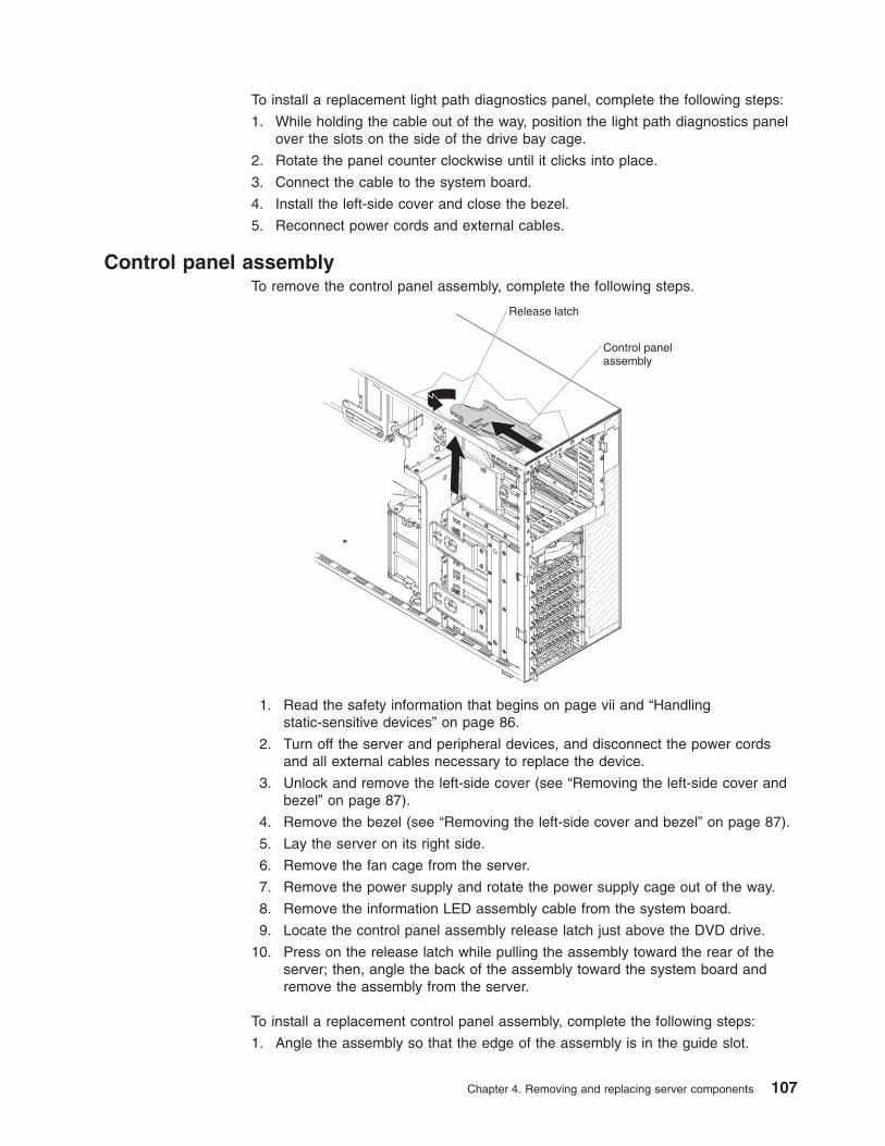
To install a replacement light path diagnostics panel, complete the following steps:
1. While holding the cable out of the way, position the light path diagnostics panel
over the slots on the side of the drive bay cage.
2. Rotate the panel counter clockwise until it clicks into place.
3. Connect the cable to the system board.
4. Install the left-side cover and close the bezel.
5. Reconnect power cords and external cables.
Control panel assembly
To remove the control panel assembly, complete the following steps.
Release latch
Control panelassembly
1. Read the safety information that begins on page vii and “Handling
static-sensitive devices” on page 86.
2. Turn off the server and peripheral devices, and disconnect the power cords
and all external cables necessary to replace the device.
3. Unlock and remove the left-side cover (see “Removing the left-side cover and
bezel” on page 87).
4. Remove the bezel (see “Removing the left-side cover and bezel” on page 87).
5. Lay the server on its right side.
6. Remove the fan cage from the server.
7. Remove the power supply and rotate the power supply cage out of the way.
8. Remove the information LED assembly cable from the system board.
9. Locate the control panel assembly release latch just above the DVD drive.
10. Press on the release latch while pulling the assembly toward the rear of the
server; then, angle the back of the assembly toward the system board and
remove the assembly from the server.
To install a replacement control panel assembly, complete the following steps:
1. Angle the assembly so that the edge of the assembly is in the guide slot.
Chapter 4. Removing and replacing server components 107
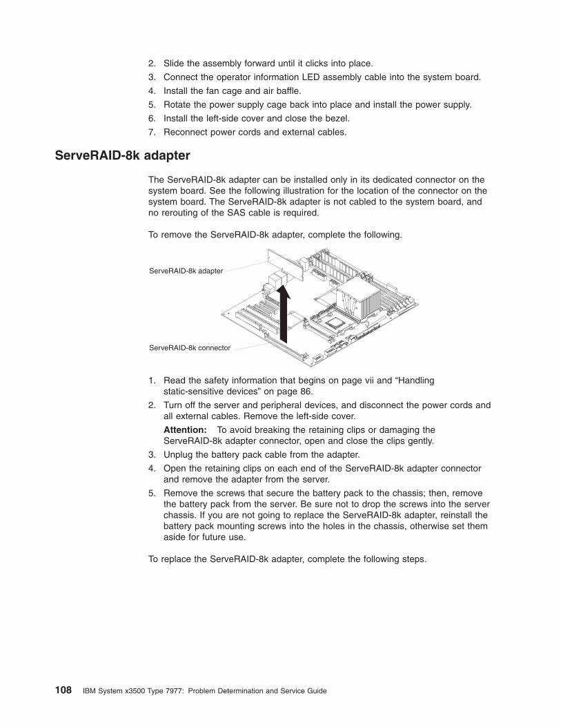
2. Slide the assembly forward until it clicks into place.
3. Connect the operator information LED assembly cable into the system board.
4. Install the fan cage and air baffle.
5. Rotate the power supply cage back into place and install the power supply.
6. Install the left-side cover and close the bezel.
7. Reconnect power cords and external cables.
ServeRAID-8k adapter
The ServeRAID-8k adapter can be installed only in its dedicated connector on the
system board. See the following illustration for the location of the connector on the
system board. The ServeRAID-8k adapter is not cabled to the system board, and
no rerouting of the SAS cable is required.
To remove the ServeRAID-8k adapter, complete the following.
ServeRAID-8k connector
ServeRAID-8k adapter
1. Read the safety information that begins on page vii and “Handling
static-sensitive devices” on page 86.
2. Turn off the server and peripheral devices, and disconnect the power cords and
all external cables. Remove the left-side cover.
Attention: To avoid breaking the retaining clips or damaging the
ServeRAID-8k adapter connector, open and close the clips gently.
3. Unplug the battery pack cable from the adapter.
4. Open the retaining clips on each end of the ServeRAID-8k adapter connector
and remove the adapter from the server.
5. Remove the screws that secure the battery pack to the chassis; then, remove
the battery pack from the server. Be sure not to drop the screws into the server
chassis. If you are not going to replace the ServeRAID-8k adapter, reinstall the
battery pack mounting screws into the holes in the chassis, otherwise set them
aside for future use.
To replace the ServeRAID-8k adapter, complete the following steps.
108 IBM System x3500 Type 7977: Problem Determination and Service Guide

ServeRAID-8k connector
ServeRAID-8k adapter
1. Open the retaining clips on each end of the ServeRAID-8k adapter connector.
2. Touch the static-protective package that contains the ServeRAID-8k adapter to
any unpainted metal surface on the server. Then, remove the ServeRAID-8k
adapter and battery pack from the package.
3. Connect the battery pack cable to the ServeRAID-8k adapter.
4. Turn the ServeRAID-8k adapter so that the ServeRAID-8k adapter keys align
correctly with the connector.
Attention: Incomplete insertion might cause damage to the system board or
the ServeRAID-8k adapter.
5. Press the ServeRAID-8k adapter firmly into the connector.
6. Mount the battery pack to the chassis, using the two mounting screws.
7. Plug the battery pack cable into the connector on the adapter.
FRU information
Important: The field-replaceable unit (FRU) procedures are intended for trained
service technicians who are familiar with IBM System x products.
Chapter 4. Removing and replacing server components 109
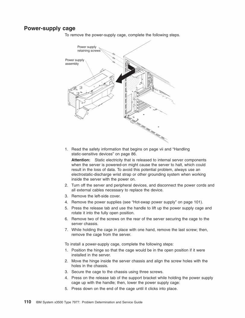
Power-supply cage
To remove the power-supply cage, complete the following steps.
Power supplyassembly
Power supplyretaining screws
1. Read the safety information that begins on page vii and “Handling
static-sensitive devices” on page 86.
Attention: Static electricity that is released to internal server components
when the server is powered-on might cause the server to halt, which could
result in the loss of data. To avoid this potential problem, always use an
electrostatic-discharge wrist strap or other grounding system when working
inside the server with the power on.
2. Turn off the server and peripheral devices, and disconnect the power cords and
all external cables necessary to replace the device.
3. Remove the left-side cover.
4. Remove the power supplies (see “Hot-swap power supply” on page 101).
5. Press the release tab and use the handle to lift up the power supply cage and
rotate it into the fully open position.
6. Remove two of the screws on the rear of the server securing the cage to the
server chassis.
7. While holding the cage in place with one hand, remove the last screw; then,
remove the cage from the server.
To install a power-supply cage, complete the following steps:
1. Position the hinge so that the cage would be in the open position if it were
installed in the server.
2. Move the hinge inside the server chassis and align the screw holes with the
holes in the chassis.
3. Secure the cage to the chassis using three screws.
4. Press on the release tab of the support bracket while holding the power supply
cage up with the handle; then, lower the power supply cage:
5. Press down on the end of the cage until it clicks into place.
110 IBM System x3500 Type 7977: Problem Determination and Service Guide
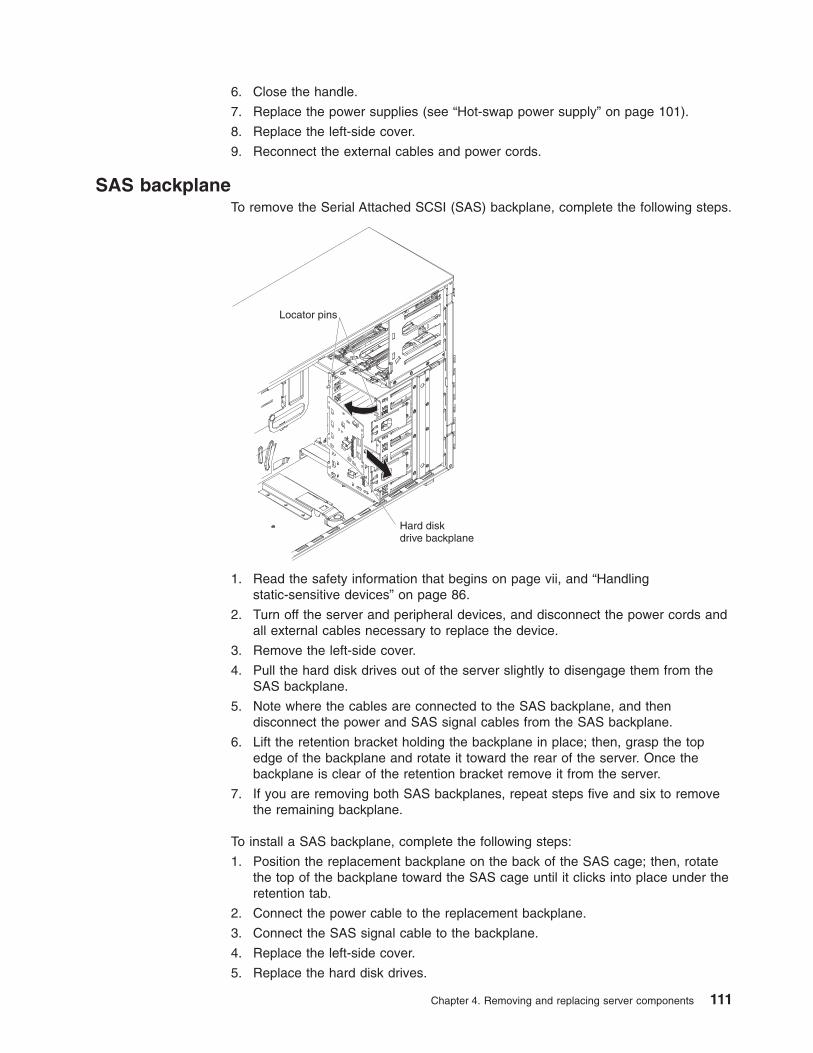
6. Close the handle.
7. Replace the power supplies (see “Hot-swap power supply” on page 101).
8. Replace the left-side cover.
9. Reconnect the external cables and power cords.
SAS backplane
To remove the Serial Attached SCSI (SAS) backplane, complete the following steps.
Hard diskdrive backplane
Locator pins
1. Read the safety information that begins on page vii, and “Handling
static-sensitive devices” on page 86.
2. Turn off the server and peripheral devices, and disconnect the power cords and
all external cables necessary to replace the device.
3. Remove the left-side cover.
4. Pull the hard disk drives out of the server slightly to disengage them from the
SAS backplane.
5. Note where the cables are connected to the SAS backplane, and then
disconnect the power and SAS signal cables from the SAS backplane.
6. Lift the retention bracket holding the backplane in place; then, grasp the top
edge of the backplane and rotate it toward the rear of the server. Once the
backplane is clear of the retention bracket remove it from the server.
7. If you are removing both SAS backplanes, repeat steps five and six to remove
the remaining backplane.
To install a SAS backplane, complete the following steps:
1. Position the replacement backplane on the back of the SAS cage; then, rotate
the top of the backplane toward the SAS cage until it clicks into place under the
retention tab.
2. Connect the power cable to the replacement backplane.
3. Connect the SAS signal cable to the backplane.
4. Replace the left-side cover.
5. Replace the hard disk drives.
Chapter 4. Removing and replacing server components 111
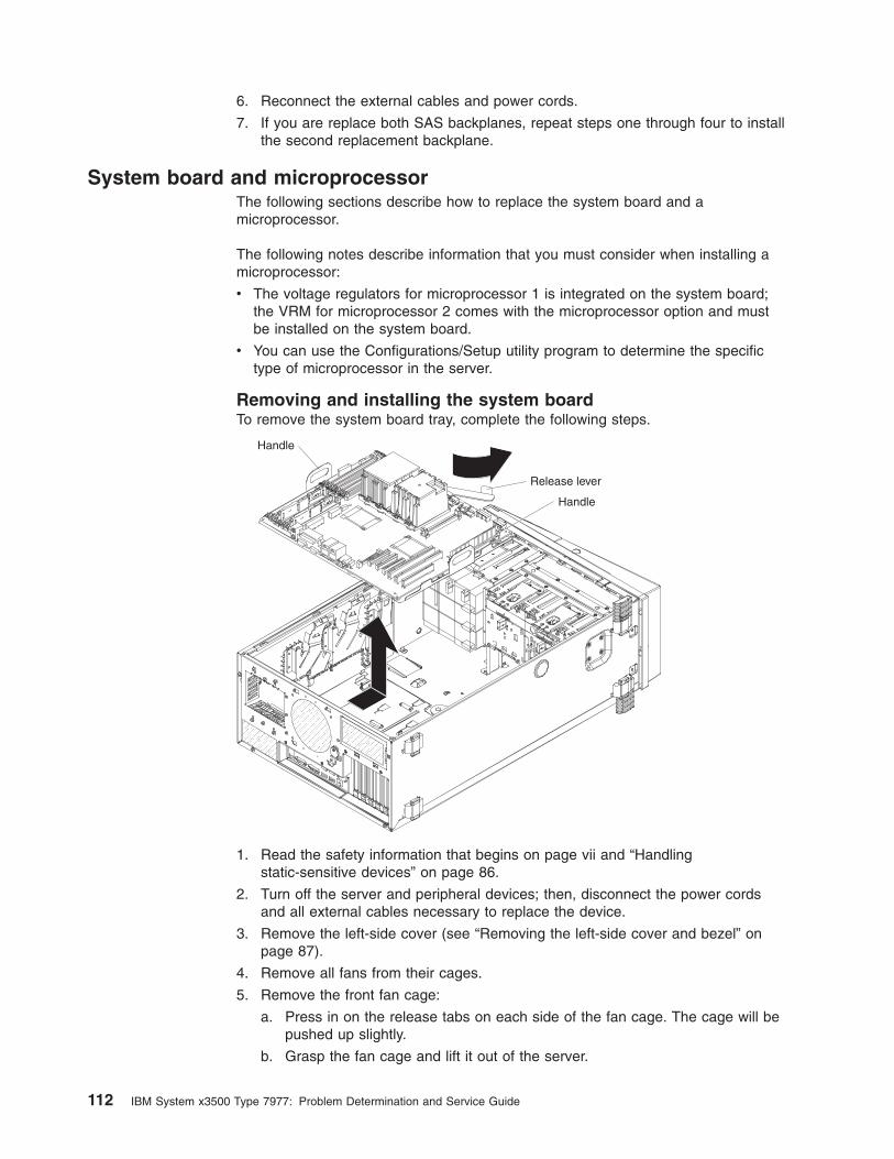
6. Reconnect the external cables and power cords.
7. If you are replace both SAS backplanes, repeat steps one through four to install
the second replacement backplane.
System board and microprocessor
The following sections describe how to replace the system board and a
microprocessor.
The following notes describe information that you must consider when installing a
microprocessor:
v The voltage regulators for microprocessor 1 is integrated on the system board;
the VRM for microprocessor 2 comes with the microprocessor option and must
be installed on the system board.
v You can use the Configurations/Setup utility program to determine the specific
type of microprocessor in the server.
Removing and installing the system board
To remove the system board tray, complete the following steps.
Release lever
Handle
Handle
1. Read the safety information that begins on page vii and “Handling
static-sensitive devices” on page 86.
2. Turn off the server and peripheral devices; then, disconnect the power cords
and all external cables necessary to replace the device.
3. Remove the left-side cover (see “Removing the left-side cover and bezel” on
page 87).
4. Remove all fans from their cages.
5. Remove the front fan cage:
a. Press in on the release tabs on each side of the fan cage. The cage will be
pushed up slightly.
b. Grasp the fan cage and lift it out of the server.
112 IBM System x3500 Type 7977: Problem Determination and Service Guide
6. If necessary remove the rear fans structure:
a. Lift or remove the air duct from the cage.
b. Grasp the rear fan cage and lift it up until it disengages from the pins on the
chassis; then, remove it from the server.
7. Note the location of all the cables connected to the system board; then,
disconnect them. If the rear fan was installed you will have to remove the fan
power cable from the server. Place the cable in a safe place for future use.
8. Press the system-board tray release latch toward the front of the server.
9. Using the two handles on each side of the system-board tray, lift the
system-board tray out of the server.
To install a system-board tray, complete the following steps:
1. Lower the replacement system-board tray into the server.
2. Slide the microprocessors system-board tray toward the rear of the server until
it stops; then close the system-board tray release lever. The system-board tray
will be pushed into its final position.
3. Connect the cables to the system board. If you removed the rear fan power
cable install it now as well.
4. Install the microprocessor or microprocessors (see “Removing and installing a
microprocessor”); then, install the fans, fans cage or cages, and air baffles.
Removing and installing a microprocessor
To remove a microprocessor, complete the following steps:
1. Read the safety information that begins on page vii and “Handling
static-sensitive devices” on page 86.
2. Turn off the server and peripheral devices, and disconnect the power cords and
all external cables necessary to replace the device.
3. Remove the left-side cover (see “Removing the left-side cover and bezel” on
page 87).
Notes:
a. If you are removing the microprocessor in socket 1, rotate the power supply
cage out of the way before continuing. See “Power-supply cage” on page
110.
b. If you are removing the microprocessor in socket 2, remove the air baffle
from the fan cage by pinching the two tabs on the air baffle together while
lifting the air baffle out of the server.
c. Do not mix dual-core and quad-core processors in the same system.
4. Lift the heat-sink release lever to the fully open position.
5. Rotate the back of the heat sink out of the retention bracket and remove the
heat sink from the server.
6. Lift the microprocessor-release lever to the fully open position (approximately
135° angle) and remove the microprocessor from the server.
To install a microprocessor, complete the following steps:
1. Release the microprocessor retention latch by pressing down on the end,
moving it to the side, and slowly releasing it to the open (up) position.
Chapter 4. Removing and replacing server components 113
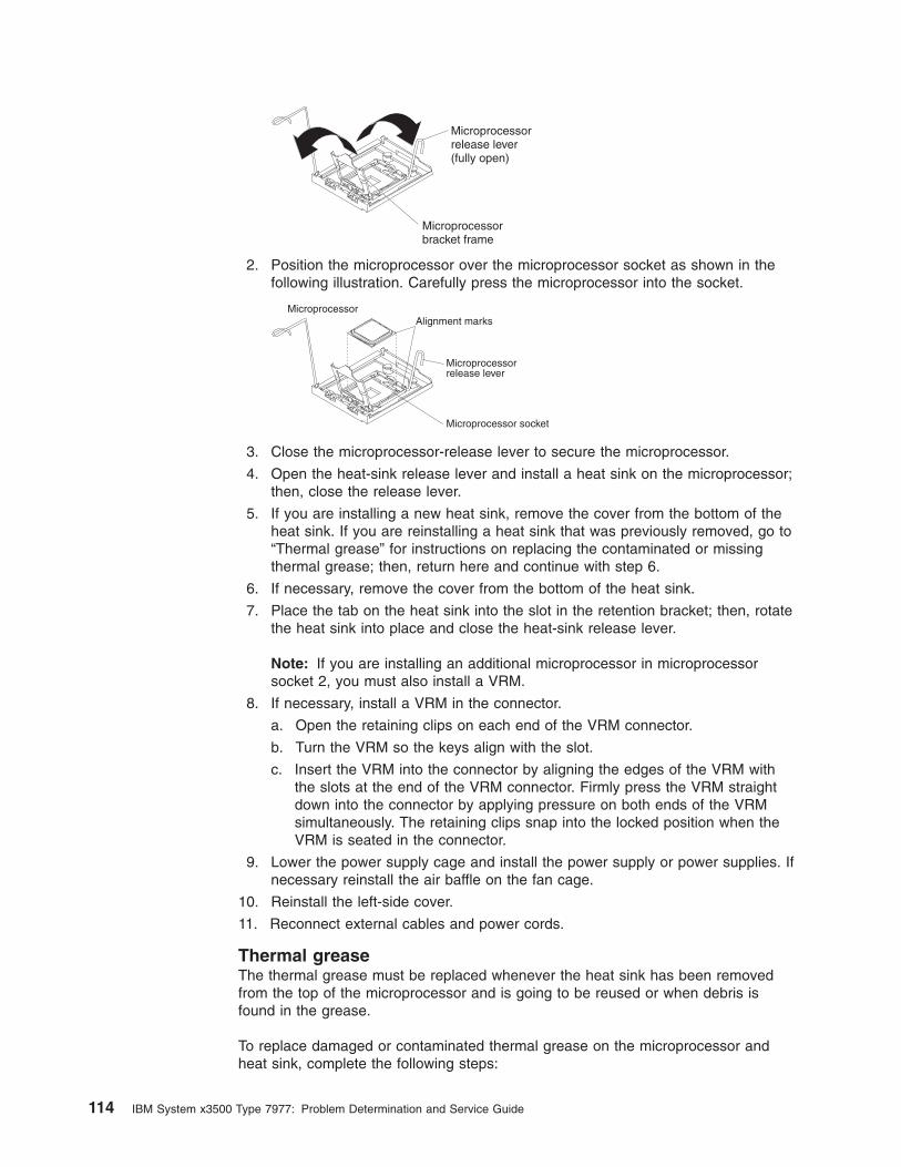
Microprocessorrelease lever(fully open)
Microprocessorbracket frame
2. Position the microprocessor over the microprocessor socket as shown in the
following illustration. Carefully press the microprocessor into the socket.
Microprocessor
Microprocessor socket
Microprocessorrelease lever
Alignment marks
3. Close the microprocessor-release lever to secure the microprocessor.
4. Open the heat-sink release lever and install a heat sink on the microprocessor;
then, close the release lever.
5. If you are installing a new heat sink, remove the cover from the bottom of the
heat sink. If you are reinstalling a heat sink that was previously removed, go to
“Thermal grease” for instructions on replacing the contaminated or missing
thermal grease; then, return here and continue with step 6.
6. If necessary, remove the cover from the bottom of the heat sink.
7. Place the tab on the heat sink into the slot in the retention bracket; then, rotate
the heat sink into place and close the heat-sink release lever.
Note: If you are installing an additional microprocessor in microprocessor
socket 2, you must also install a VRM.
8. If necessary, install a VRM in the connector.
a. Open the retaining clips on each end of the VRM connector.
b. Turn the VRM so the keys align with the slot.
c. Insert the VRM into the connector by aligning the edges of the VRM with
the slots at the end of the VRM connector. Firmly press the VRM straight
down into the connector by applying pressure on both ends of the VRM
simultaneously. The retaining clips snap into the locked position when the
VRM is seated in the connector.
9. Lower the power supply cage and install the power supply or power supplies. If
necessary reinstall the air baffle on the fan cage.
10. Reinstall the left-side cover.
11. Reconnect external cables and power cords.
Thermal grease
The thermal grease must be replaced whenever the heat sink has been removed
from the top of the microprocessor and is going to be reused or when debris is
found in the grease.
To replace damaged or contaminated thermal grease on the microprocessor and
heat sink, complete the following steps:
114 IBM System x3500 Type 7977: Problem Determination and Service Guide
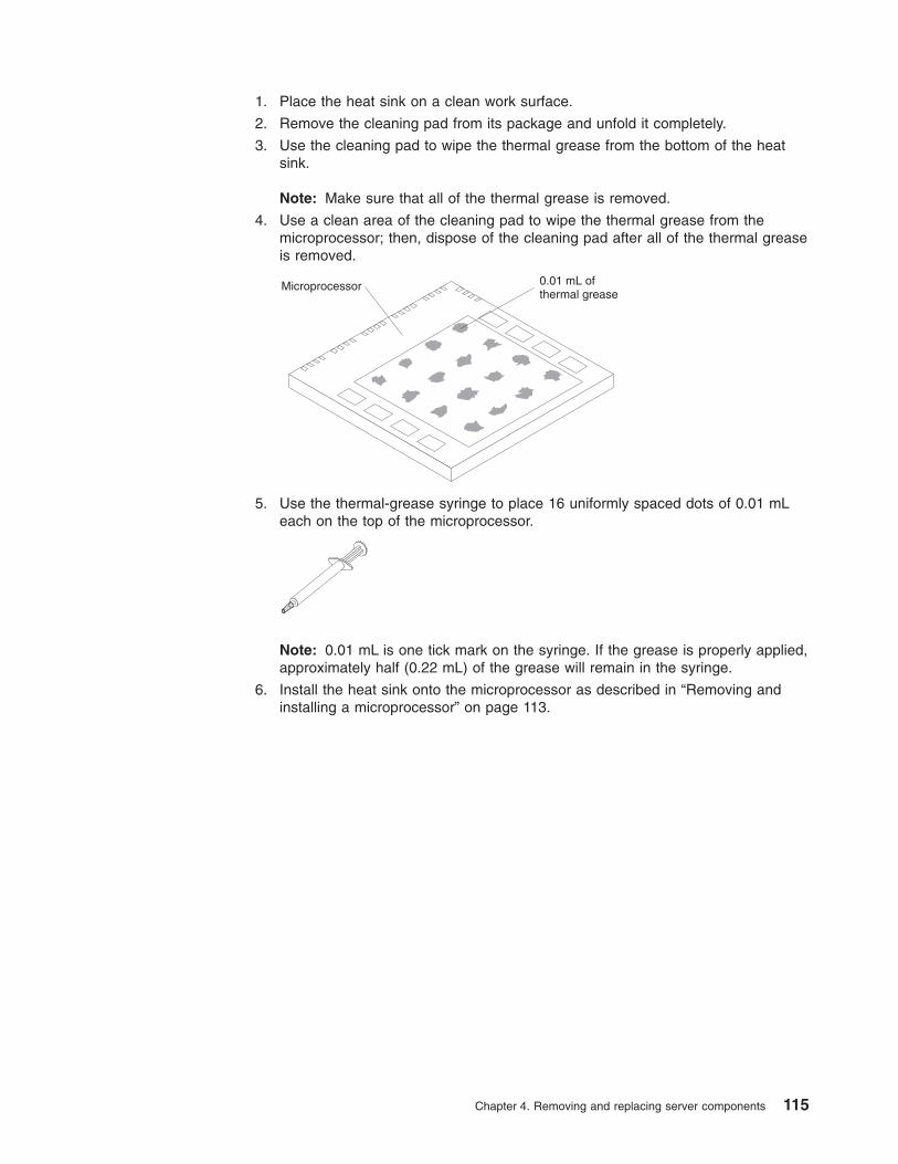
1. Place the heat sink on a clean work surface.
2. Remove the cleaning pad from its package and unfold it completely.
3. Use the cleaning pad to wipe the thermal grease from the bottom of the heat
sink.
Note: Make sure that all of the thermal grease is removed.
4. Use a clean area of the cleaning pad to wipe the thermal grease from the
microprocessor; then, dispose of the cleaning pad after all of the thermal grease
is removed.
Microprocessor 0.01 mL ofthermal grease
5. Use the thermal-grease syringe to place 16 uniformly spaced dots of 0.01 mL
each on the top of the microprocessor.
Note: 0.01 mL is one tick mark on the syringe. If the grease is properly applied,
approximately half (0.22 mL) of the grease will remain in the syringe.
6. Install the heat sink onto the microprocessor as described in “Removing and
installing a microprocessor” on page 113.
Chapter 4. Removing and replacing server components 115

116 IBM System x3500 Type 7977: Problem Determination and Service Guide
Chapter 5. Configuration information and instructions
This chapter provides information about updating the firmware and using the
configuration utilities.
Updating the firmware
The firmware in your server is periodically updated and is available for download on
the Web. Go to http://www.ibm.com/pc/support/ to check for the latest level of
firmware, such as BIOS code, vital product data (VPD) code, device drivers, and
service processor firmware.
The UpdateXpress program is available for most System x® servers and server
options. It detects supported and installed device drivers and firmware in your
server and installs available updates. You can download the UpdateXpress program
from the Web at no additional cost, or you can purchase it on a CD. To download
the program or purchase the CD, go to http://www.ibm.com/pc/ww/eserver/xseries/serverguide/xpress.html.
When replacing devices in the server, you might have to either update the server
with the latest version of the firmware stored on the board or restore the
pre-existing firmware from a diskette or CD image.
v BIOS code and the diagnostics programs are stored in ROM on the
microprocessor board.
v BMC firmware is stored in ROM on the baseboard management controller on the
microprocessor board.
v Ethernet firmware is stored in ROM on the Ethernet controller on the PCI-X
board.
v ServeRAID firmware is stored in ROM on the ServeRAID adapter.
v SAS firmware is stored in ROM on the SAS controller on the I/O board.
v Major components contain VPD code. You can select to update the VPD code
during the BIOS code update procedure.
Configuring the server
The ServerGuide Setup and Installation CD provides software setup tools and
installation tools that are specifically designed for your IBM server. Use this CD
during the initial installation of the server to configure basic hardware features and
to simplify the operating-system installation.
In addition to the ServerGuide Setup and Installation CD, you can use the following
configuration programs to customize the server hardware:
v UpdateXpress program
v Configuration/Setup Utility program
v Baseboard management controller utility programs
v Menu Boot program
v SAS/SATA Configuration Utility program
v ServeRAID Manager
© Copyright IBM Corp. 2007 117
This section contains basic information about these programs. For detailed
information about these programs, see “Configuring the server” in the User’s Guide
on the IBM xSeries Documentation CD.
Using the ServerGuide Setup and Installation CD
The ServerGuide Setup and Installation CD provides programs to detect the server
model and installed hardware options, configure the server hardware, provide
device drivers, and help you install the operating system. For information about the
supported operating-system versions, see the label on the CD. If the ServerGuide
Setup and Installation CD did not come with your server, you can download the
latest version from http://www.ibm.com/pc/qtechinfo/MIGR-4ZKPPT.html.
Complete the following steps to start the ServerGuide Setup and Installation CD:
1. Insert the CD, and restart the server.
2. Follow the instructions on the screen to:
a. Select your language.
b. Select your keyboard layout and country.
c. View the overview to learn about ServerGuide features.
d. View the readme file to review installation tips about your operating system
and adapter.
e. Start the setup and hardware configuration programs.
f. Start the operating-system installation. You will need your operating-system
CD.
Using the Configuration/Setup Utility program
Use the Configuration/Setup Utility program to:
v View configuration information
v View and change assignments for devices and I/O ports
v Set the date and time
v Set and change passwords and Remote Control Security settings
v Set the startup characteristics of the server and the order of startup devices
v Set and change settings for advanced hardware features
v Set and change settings for the mini baseboard management controller (BMC)
v View and clear error logs
Go to http://www.ibm.com/pc/support/ to check for the latest version of the BIOS
code.
Starting the Configuration/Setup Utility program
To start the Configuration/Setup Utility program, complete the following steps:
1. Turn on the server.
2. When the prompt Press F1 for Configuration/Setup appears, press F1. If you
have set both a power-on password and an administrator password, you must
type the administrator password to access the full Configuration/Setup Utility
menu. If you do not type the administrator password, a limited
Configuration/Setup Utility menu is available.
3. Select settings to view or change.
118 IBM System x3500 Type 7977: Problem Determination and Service Guide
Configuration/Setup Utility menu choices
The following choices are on the Configuration/Setup Utility main menu. Depending
on the version of the BIOS code in the server, some menu choices might differ
slightly from these descriptions.
v System Summary
Select this choice to view configuration information, including the type, speed,
and cache sizes of the microprocessors, type and speed of installed USB
devices, and the amount of installed memory. When you make configuration
changes through other options in the Configuration/Setup Utility program, the
changes are reflected in the system summary; you cannot change settings
directly in the system summary.
This choice is on the full and limited Configuration/Setup Utility menu.
v System Information
Select this choice to view information about the server. When you make changes
through other options in the Configuration/Setup Utility program, some of those
changes are reflected in the system information; you cannot change settings
directly in the system information.
v Devices and I/O Ports
Select this choice to view or change assignments for devices and input/output
(I/O) ports.
Select this choice to enable or disable integrated SAS and Ethernet controllers
and all standard ports (such as serial and parallel). Enable is the default setting
for all controllers. If you disable a device, it cannot be configured, and the
operating system will not be able to detect it (this is equivalent to disconnecting
the device). If you disable the integrated Ethernet controller and no Ethernet
adapter is installed, the server will have no Ethernet capability. If you disable the
integrated USB controller, the server will have no USB capability; to maintain
USB capability, make sure that Enabled is selected for the USB Host Controller
and USB BIOS Legacy Support options.
Note: If the USB host controller is disabled, the Remote Supervisor Adapter II
SlimLine remote keyboard, remote mouse, remote disk, OS watchdog, and
in-band management functions are also disabled.
This choice is on the full Configuration/Setup Utility menu only.
v Date and Time
Select this choice to set the date and time in the server, in 24-hour format
(hour:minute:second).
This choice is on the full Configuration/Setup Utility menu only.
v System Security
Select this choice to set passwords. See “Passwords” on page 122 for more
information about passwords. You can also enable the chassis-intrusion detector
to alert you each time the server cover is removed.
This choice is on the full Configuration/Setup Utility menu only.
– Administrator Password
Attention: If you set an administrator password and then forget it, there is
no way to change, override, or remove it. You must replace the I/O board.
Select this choice to set or change an administrator password. An
administrator password is intended to be used by a system administrator; it
limits access to the full Configuration/Setup Utility menu. If an administrator
password is set, the full Configuration/Setup Utility menu is available only if
Chapter 5. Configuration information and instructions 119
you type the administrator password at the password prompt. See
“Administrator password” on page 123 for more information.
This choice is on the Configuration/Setup Utility menu only if an IBM Remote
Supervisor Adapter II SlimLine is installed.
– Power-on Password
Select this choice to set or change a power-on password. See “Power-on
password” on page 122 for more information.
v Start Options
Select this choice to view or change the start options. Changes in the start
options take effect when you restart the server.
You can specify whether the server starts with the keyboard number lock on or
off. You can enable the server to run without a monitor or keyboard.
The startup sequence specifies the order in which the server checks devices to
find a boot record. The server starts from the first boot record that it finds. If the
server has Wake on LAN® hardware and software and the operating system
supports Wake on LAN functions, you can specify a startup sequence for the
Wake on LAN functions.
If you enable the boot fail count, the BIOS default settings will be restored after
three consecutive failures to find a boot record.
You can enable the use of a USB keyboard in a DOS or System Setup
environment. If a PS/2 keyboard is detected, the USB legacy operation will be
disabled.
This choice is on the full Configuration/Setup Utility menu only.
v Advanced Setup
Select this choice to change settings for advanced hardware features.
Important: The server might malfunction if these options are incorrectly
configured. Follow the instructions on the screen carefully.
This choice is on the full Configuration/Setup Utility menu only.
– CPU Options
Select this choice to enable or disable Hyper-Threading, the pre-fetch queue,
C1 enhanced mode, and no-execute mode memory protection.
The default setting for Hyper-Threading is Enabled.
– PCI Bus Control
Select this choice to view the system resources that are used by the installed
PCI, PCI Express, or PCI-X devices.
– IPMI
Select this choice to view or clear the system event log. Make changes to the
serial/modem device commands, the POST watchdog settings and to view the
LAN settings.
- IPMI Specification Version
This is a nonselectable menu item that displays the IPMI and BMC version.
- BMC Hardware/Firmware Version
This is a nonselectable menu item that displays the BMC firmware version.
- Clear System Event Log
Enable or disable the system event log clearing. If system event log
clearing is enabled, it will reset to disabled once the BMC system-event log
is cleared. Disabled is the default setting.
120 IBM System x3500 Type 7977: Problem Determination and Service Guide
- Existing Event Log number
This is a nonselectable menu item that displays the number of entries in
the system-event log.
- BIOS POST Watchdog
Enable or disable the BMC POST watchdog. Disabled is the default
setting.
- POST Watchdog Timeout
Set the BMC POST watchdog timeout value. 5 minutes is the default
setting.
- System Event Log
Select this choice to view the BMC system-event log, which contains all
system error and warning messages that have been generated. Use the
arrow keys to move between pages in the log. If an optional IBM Remote
Supervisor Adapter II is installed, the full text of the error messages is
displayed; otherwise, the log contains only numeric error codes. Run the
diagnostic program to get more information about error codes that occur.
Select Clear System Event Log to clear the BMC system-event log.
Important: If the system-error LED on the front of the server is lit but there
are no other error indications, clear the BMC system-event log. This log
does not clear itself, and if it begins to fill up, the system-error LED will be
lit. Also, after you complete a repair or correct an error, clear the BMC
system-event log to turn off the system-error LED on the front of the server.
- Serial /Modem Device Commands
Select this choice to change the serial port sharing and access mode.
v Serial Port Sharing
Enable or disable serial port sharing. Enabled is the default setting.
v Serial Port Access Mode
Share, disable, pre-boot only, or always available. Shared is the default
setting.
- LAN Settings
Select this choice to view the baseboard management controller network
configuration information.
– NMI Options
Select this choice to enable or disable the NMI reboot. Enabled is the default
setting.
v Error Logs
Select this choice to view or clear error logs.
– POST Error Log
Select this choice to view the three most recent error codes and messages
that the system generated during POST. For more information on error logs
see, IPMI on page 120.
– System Event/Error Log
Select this choice to view error codes and messages that the system
generated during POST and all system status messages from the service
processor. Select Clear error logs to clear the system event/error log. For
more information on error logs see, IPMI on page 120.
Important: If the system-error LED on the front of the server is lit but there
are no other error indications, clear the system event/error log. This log does
not clear itself, and if it begins to fill up, the system-error LED will be lit. Also,
after you complete a repair or correct an error, clear the system event/error
log to turn off the system-error LED on the front of the server.
v Save Settings
Chapter 5. Configuration information and instructions 121
Select this choice to save the changes you have made in the settings.
v Restore Settings
Select this choice to cancel the changes you have made in the settings and
restore the previous settings.
v Load Default Settings
Select this choice to cancel the changes you have made in the settings and
restore the factory settings.
v Exit Setup
Select this choice to exit from the Configuration/Setup Utility program. If you have
not saved the changes you have made in the settings, you are asked whether
you want to save the changes or exit without saving them.
Passwords
From the System Security choice, you can set, change, and delete a power-on
password and an administrator password. The System Security choice is on the
full Configuration/Setup menu only.
If you set only a power-on password, you must type the power-on password to
complete the system startup, and you have access to the full Configuration/Setup
Utility menu.
An administrator password is intended to be used by a system administrator; it
limits access to the full Configuration/Setup Utility menu. If you set only an
administrator password, you do not have to type a password to complete the
system startup, but you must type the administrator password to access the
Configuration/Setup Utility menu.
If you set a power-on password for a user and an administrator password for a
system administrator, you can type either password to complete the system startup.
A system administrator who types the administrator password has access to the full
Configuration/Setup Utility menu; the system administrator can give the user
authority to set, change, and delete the power-on password. A user who types the
power-on password has access to only the limited Configuration/Setup Utility menu;
the user can set, change, and delete the power-on password, if the system
administrator has given the user that authority.
Power-on password: If a power-on password is set, when you turn on the server,
the system startup will not be completed until you type the power-on password. You
can use any combination of up to seven characters (A–Z, a–z, and 0–9) for the
password.
When a power-on password is set, you can enable the Unattended Start mode, in
which the keyboard and mouse remain locked but the operating system can start.
You can unlock the keyboard and mouse by typing the power-on password.
If you forget the power-on password, you can regain access to the server in any of
the following ways:
v If an administrator password is set, type the administrator password at the
password prompt. Start the Configuration/Setup Utility program and reset the
power-on password.
v Remove the server battery and then reinstall it. See “Battery” on page 90 for
instructions for removing the battery.
v Toggle switch 2 of SW4 on the system board to the On position to bypass the
power-on password check.
122 IBM System x3500 Type 7977: Problem Determination and Service Guide
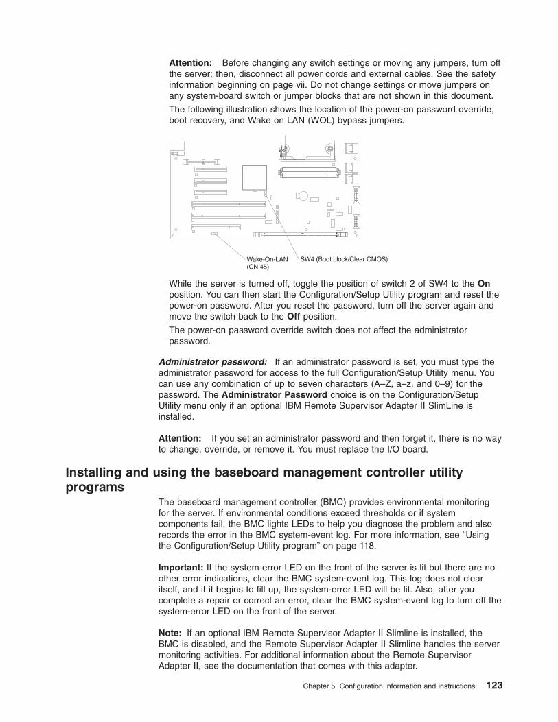
Attention: Before changing any switch settings or moving any jumpers, turn off
the server; then, disconnect all power cords and external cables. See the safety
information beginning on page vii. Do not change settings or move jumpers on
any system-board switch or jumper blocks that are not shown in this document.
The following illustration shows the location of the power-on password override,
boot recovery, and Wake on LAN (WOL) bypass jumpers.
Wake-On-LAN(CN 45)
SW4 (Boot block/Clear CMOS)
While the server is turned off, toggle the position of switch 2 of SW4 to the On
position. You can then start the Configuration/Setup Utility program and reset the
power-on password. After you reset the password, turn off the server again and
move the switch back to the Off position.
The power-on password override switch does not affect the administrator
password.
Administrator password: If an administrator password is set, you must type the
administrator password for access to the full Configuration/Setup Utility menu. You
can use any combination of up to seven characters (A–Z, a–z, and 0–9) for the
password. The Administrator Password choice is on the Configuration/Setup
Utility menu only if an optional IBM Remote Supervisor Adapter II SlimLine is
installed.
Attention: If you set an administrator password and then forget it, there is no way
to change, override, or remove it. You must replace the I/O board.
Installing and using the baseboard management controller utility
programs
The baseboard management controller (BMC) provides environmental monitoring
for the server. If environmental conditions exceed thresholds or if system
components fail, the BMC lights LEDs to help you diagnose the problem and also
records the error in the BMC system-event log. For more information, see “Using
the Configuration/Setup Utility program” on page 118.
Important: If the system-error LED on the front of the server is lit but there are no
other error indications, clear the BMC system-event log. This log does not clear
itself, and if it begins to fill up, the system-error LED will be lit. Also, after you
complete a repair or correct an error, clear the BMC system-event log to turn off the
system-error LED on the front of the server.
Note: If an optional IBM Remote Supervisor Adapter II Slimline is installed, the
BMC is disabled, and the Remote Supervisor Adapter II Slimline handles the server
monitoring activities. For additional information about the Remote Supervisor
Adapter II, see the documentation that comes with this adapter.
Chapter 5. Configuration information and instructions 123
Using the SAS/SATA Configuration Utility program
Use the SAS/SATA Configuration Utility program to view or change SAS controller
settings.
To start the SAS/SATA Configuration Utility program, complete the following steps:
1. Turn on the server.
2. When the message Press <CTRL><A> for Adaptec SAS/SATA Configuration
Utility appears, press Ctrl+A. If an administrator password has been set, you
are prompted to type the password.
3. Follow the instructions on the screen to configure the controller settings.
Go to http://www.ibm.com/support/ to check for the latest version of the SAS
firmware.
Configuring the Ethernet controller
The Ethernet controller is integrated on the system board. It provides an interface
for connecting to a 10-Mbps, 100-Mbps, or 1-Gbps network and provides full duplex
(FDX) capability, which enables simultaneous transmission and reception of data on
the network. If the Ethernet port in the server supports auto-negotiation, the
controller detects the data-transfer rate (10BASE-T, 100BASE-TX, or 1000BASE-T)
and duplex mode (full-duplex or half-duplex) of the network and automatically
operates at that rate and mode.
You do not have to set any jumpers or configure the controller. However, you must
install a device driver to enable the operating system to address the controller. To
find updated information about configuring the controller, complete the following
steps.
Note: Changes are made periodically to the IBM Web site. The actual procedure
might vary slightly from what is described in this document.
1. Go to http://www.ibm.com/support/.
2. Under Search technical support, type 7977, and click Search.
3. In the Additional search terms field, type ethernet, and click Go.
Using the ServeRAID Manager
Use ServeRAID Manager, which is on the IBM ServeRAID Support CD, to perform
the following tasks:
v Configure a redundant array of independent disks (RAID) array
v Erase all data from a hot-swap SAS hard disk drive and return the disk to the
factory-default settings
v View the RAID configuration and associated devices
v Monitor the operation of the RAID controllers
To perform some tasks, you can run ServeRAID Manager as an installed program.
However, to configure the SAS/SATA controller and perform an initial RAID
configuration on the server, you must run ServeRAID Manager in Startable CD
mode, as described in the instructions in this section. If you install a different type of
RAID adapter in the server, use the method that is described in the instructions that
come with the adapter to view or change settings for attached devices.
For additional information about RAID technology and instructions for using
ServeRAID Manager, see the ServeRAID documentation on the IBM ServeRAID
124 IBM System x3500 Type 7977: Problem Determination and Service Guide
Support CD. Additional information about ServeRAID Manager is also available from
the Help menu. For information about a specific object in the ServeRAID Manager
tree, select the object and click Actions → Hints and tips.
Chapter 5. Configuration information and instructions 125

126 IBM System x3500 Type 7977: Problem Determination and Service Guide
Appendix A. Getting help and technical assistance
If you need help, service, or technical assistance or just want more information
about IBM products, you will find a wide variety of sources available from IBM to
assist you. This appendix contains information about where to go for additional
information about IBM and IBM products, what to do if you experience a problem
with your system or optional device, and whom to call for service, if it is necessary.
Before you call
Before you call, make sure that you have taken these steps to try to solve the
problem yourself:
v Check all cables to make sure that they are connected.
v Check the power switches to make sure that the system and any optional
devices are turned on.
v Use the troubleshooting information in your system documentation, and use the
diagnostic tools that come with your system. Information about diagnostic tools is
in the Hardware Maintenance Manual and Troubleshooting Guide or Problem
Determination and Service Guide on the IBM Documentation CD that comes with
your system.
Note: For some IntelliStation models, the Hardware Maintenance Manual and
Troubleshooting Guide is available only from the IBM support Web site.
v Go to the IBM support Web site at http://www.ibm.com/servers/eserver/support/xseries/index.html to check for technical information, hints, tips, and new device
drivers or to submit a request for information.
You can solve many problems without outside assistance by following the
troubleshooting procedures that IBM provides in the online help or in the
documentation that is provided with your IBM product. The documentation that
comes with IBM systems also describes the diagnostic tests that you can perform.
Most systems, operating systems, and programs come with documentation that
contains troubleshooting procedures and explanations of error messages and error
codes. If you suspect a software problem, see the documentation for the operating
system or program.
Using the documentation
Information about your IBM system and preinstalled software, if any, or optional
device is available in the documentation that comes with the product. That
documentation can include printed documents, online documents, readme files, and
help files. See the troubleshooting information in your system documentation for
instructions for using the diagnostic programs. The troubleshooting information or
the diagnostic programs might tell you that you need additional or updated device
drivers or other software. IBM maintains pages on the World Wide Web where you
can get the latest technical information and download device drivers and updates.
To access these pages, go to http://www.ibm.com/servers/eserver/support/xseries/index.html and follow the instructions. Also, some documents are available through
the IBM Publications Center at http://www.ibm.com/shop/publications/order/.
© Copyright IBM Corp. 2007 127
Getting help and information from the World Wide Web
On the World Wide Web, the IBM Web site has up-to-date information about IBM
systems, optional devices, services, and support. The address for IBM System x
and xSeries information is http://www.ibm.com/systems/x/. The address for IBM
IntelliStation information is http://www.ibm.com/intellistation/.
You can find service information for IBM systems and optional devices at
http://www.ibm.com/servers/eserver/support/xseries/index.html.
Software service and support
Through IBM Support Line, you can get telephone assistance, for a fee, with usage,
configuration, and software problems with System x and xSeries servers,
BladeCenter products, IntelliStation workstations, and appliances. For information
about which products are supported by Support Line in your country or region, see
http://www.ibm.com/services/sl/products/.
For more information about Support Line and other IBM services, see
http://www.ibm.com/services/, or see http://www.ibm.com/planetwide/ for support
telephone numbers. In the U.S. and Canada, call 1-800-IBM-SERV
(1-800-426-7378).
Hardware service and support
You can receive hardware service through IBM Services or through your IBM
reseller, if your reseller is authorized by IBM to provide warranty service. See
http://www.ibm.com/planetwide/ for support telephone numbers, or in the U.S. and
Canada, call 1-800-IBM-SERV (1-800-426-7378).
In the U.S. and Canada, hardware service and support is available 24 hours a day,
7 days a week. In the U.K., these services are available Monday through Friday,
from 9 a.m. to 6 p.m.
128 IBM System x3500 Type 7977: Problem Determination and Service Guide
Appendix B. Notices
This publication was developed for products and services offered in the U.S.A.
IBM may not offer the products, services, or features discussed in this document in
other countries. Consult your local IBM representative for information on the
products and services currently available in your area. Any reference to an IBM
product, program, or service is not intended to state or imply that only that IBM
product, program, or service may be used. Any functionally equivalent product,
program, or service that does not infringe any IBM intellectual property right may be
used instead. However, it is the user’s responsibility to evaluate and verify the
operation of any non-IBM product, program, or service.
IBM may have patents or pending patent applications covering subject matter
described in this document. The furnishing of this document does not give you any
license to these patents. You can send license inquiries, in writing, to:
IBM Director of Licensing
IBM Corporation
North Castle Drive
Armonk, NY 10504-1785
U.S.A.
INTERNATIONAL BUSINESS MACHINES CORPORATION PROVIDES THIS
PUBLICATION “AS IS” WITHOUT WARRANTY OF ANY KIND, EITHER EXPRESS
OR IMPLIED, INCLUDING, BUT NOT LIMITED TO, THE IMPLIED WARRANTIES
OF NON-INFRINGEMENT, MERCHANTABILITY OR FITNESS FOR A
PARTICULAR PURPOSE. Some jurisdictions do not allow disclaimer of express or
implied warranties in certain transactions, therefore, this statement may not apply to
you.
This information could include technical inaccuracies or typographical errors.
Changes are periodically made to the information herein; these changes will be
incorporated in new editions of the publication. IBM may make improvements and/or
changes in the product(s) and/or the program(s) described in this publication at any
time without notice.
Any references in this publication to non-IBM Web sites are provided for
convenience only and do not in any manner serve as an endorsement of those
Web sites. The materials at those Web sites are not part of the materials for this
IBM product, and use of those Web sites is at your own risk.
IBM may use or distribute any of the information you supply in any way it believes
appropriate without incurring any obligation to you.
Trademarks
The following terms are trademarks of International Business Machines Corporation
in the United States, other countries, or both:
Active Memory IBM (logo) Tivoli
Active PCI IntelliStation Tivoli Enterprise
Active PCI-X NetBAY Update Connector
Alert on LAN Netfinity Wake on LAN
BladeCenter Predictive Failure Analysis XA-32
© Copyright IBM Corp. 2007 129
Chipkill ServeRAID XA-64
e-business logo ServerGuide X-Architecture
Eserver ServerProven XpandOnDemand
FlashCopy System x xSeries
IBM TechConnect
Intel, Intel Xeon, Itanium, and Pentium are trademarks or registered trademarks of
Intel Corporation or its subsidiaries in the United States and other countries.
Microsoft, Windows, and Windows NT are trademarks of Microsoft Corporation in
the United States, other countries, or both.
UNIX is a registered trademark of The Open Group in the United States and other
countries.
Java and all Java-based trademarks and logos are trademarks of Sun
Microsystems, Inc. in the United States, other countries, or both.
Adaptec and HostRAID are trademarks of Adaptec, Inc., in the United States, other
countries, or both.
Linux is a trademark of Linus Torvalds in the United States, other countries, or both.
Red Hat, the Red Hat “Shadow Man” logo, and all Red Hat-based trademarks and
logos are trademarks or registered trademarks of Red Hat, Inc., in the United States
and other countries.
Other company, product, or service names may be trademarks or service marks of
others.
Important notes
Processor speeds indicate the internal clock speed of the microprocessor; other
factors also affect application performance.
CD drive speeds list the variable read rate. Actual speeds vary and are often less
than the maximum possible.
When referring to processor storage, real and virtual storage, or channel volume,
KB stands for approximately 1000 bytes, MB stands for approximately 1 000 000
bytes, and GB stands for approximately 1 000 000 000 bytes.
When referring to hard disk drive capacity or communications volume, MB stands
for 1 000 000 bytes, and GB stands for 1 000 000 000 bytes. Total user-accessible
capacity may vary depending on operating environments.
Maximum internal hard disk drive capacities assume the replacement of any
standard hard disk drives and population of all hard disk drive bays with the largest
currently supported drives available from IBM.
Maximum memory may require replacement of the standard memory with an
optional memory module.
130 IBM System x3500 Type 7977: Problem Determination and Service Guide
IBM makes no representation or warranties regarding non-IBM products and
services that are ServerProven®, including but not limited to the implied warranties
of merchantability and fitness for a particular purpose. These products are offered
and warranted solely by third parties.
IBM makes no representations or warranties with respect to non-IBM products.
Support (if any) for the non-IBM products is provided by the third party, not IBM.
Some software may differ from its retail version (if available), and may not include
user manuals or all program functionality.
Product recycling and disposal
This unit must be recycled or discarded according to applicable local and national
regulations. IBM encourages owners of information technology (IT) equipment to
responsibly recycle their equipment when it is no longer needed. IBM offers a
variety of product return programs and services in several countries to assist
equipment owners in recycling their IT products. Information on IBM product
recycling offerings can be found on IBM’s Internet site at http://www.ibm.com/ibm/environment/products/prp.shtml.
Esta unidad debe reciclarse o desecharse de acuerdo con lo establecido en la
normativa nacional o local aplicable. IBM recomienda a los propietarios de equipos
de tecnología de la información (TI) que reciclen responsablemente sus equipos
cuando éstos ya no les sean útiles. IBM dispone de una serie de programas y
servicios de devolución de productos en varios países, a fin de ayudar a los
propietarios de equipos a reciclar sus productos de TI. Se puede encontrar
información sobre las ofertas de reciclado de productos de IBM en el sitio web de
IBM http://www.ibm.com/ibm/environment/products/prp.shtml.
Notice: This mark applies only to countries within the European Union (EU) and
Norway.
This appliance is labeled in accordance with European Directive 2002/96/EC
concerning waste electrical and electronic equipment (WEEE). The Directive
determines the framework for the return and recycling of used appliances as
applicable throughout the European Union. This label is applied to various products
to indicate that the product is not to be thrown away, but rather reclaimed upon end
of life per this Directive.
Appendix B. Notices 131
Remarque : Cette marque s’applique uniquement aux pays de l’Union Européenne
et à la Norvège.
L’etiquette du système respecte la Directive européenne 2002/96/EC en matière de
Déchets des Equipements Electriques et Electroniques (DEEE), qui détermine les
dispositions de retour et de recyclage applicables aux systèmes utilisés à travers
l’Union européenne. Conformément à la directive, ladite étiquette précise que le
produit sur lequel elle est apposée ne doit pas être jeté mais être récupéré en fin
de vie.
In accordance with the European WEEE Directive, electrical and electronic
equipment (EEE) is to be collected separately and to be reused, recycled, or
recovered at end of life. Users of EEE with the WEEE marking per Annex IV of the
WEEE Directive, as shown above, must not dispose of end of life EEE as unsorted
municipal waste, but use the collection framework available to customers for the
return, recycling, and recovery of WEEE. Customer participation is important to
minimize any potential effects of EEE on the environment and human health due to
the potential presence of hazardous substances in EEE. For proper collection and
treatment, contact your local IBM representative.
Battery return program
This product may contain a sealed lead acid, nickel cadmium, nickel metal hydride,
lithium, or lithium ion battery. Consult your user manual or service manual for
specific battery information. The battery must be recycled or disposed of properly.
Recycling facilities may not be available in your area. For information on disposal of
batteries outside the United States, go to http://www.ibm.com/ibm/environment/products/batteryrecycle.shtml or contact your local waste disposal facility.
In the United States, IBM has established a return process for reuse, recycling, or
proper disposal of used IBM sealed lead acid, nickel cadmium, nickel metal hydride,
and battery packs from IBM equipment. For information on proper disposal of these
batteries, contact IBM at 1-800-426-4333. Have the IBM part number listed on the
battery available prior to your call.
In the Netherlands, the following applies.
For Taiwan: Please recycle batteries.
132 IBM System x3500 Type 7977: Problem Determination and Service Guide

Electronic emission notices
Federal Communications Commission (FCC) statement
Note: This equipment has been tested and found to comply with the limits for a
Class A digital device, pursuant to Part 15 of the FCC Rules. These limits are
designed to provide reasonable protection against harmful interference when the
equipment is operated in a commercial environment. This equipment generates,
uses, and can radiate radio frequency energy and, if not installed and used in
accordance with the instruction manual, may cause harmful interference to radio
communications. Operation of this equipment in a residential area is likely to cause
harmful interference, in which case the user will be required to correct the
interference at his own expense.
Properly shielded and grounded cables and connectors must be used in order to
meet FCC emission limits. IBM is not responsible for any radio or television
interference caused by using other than recommended cables and connectors or by
unauthorized changes or modifications to this equipment. Unauthorized changes or
modifications could void the user’s authority to operate the equipment.
This device complies with Part 15 of the FCC Rules. Operation is subject to the
following two conditions: (1) this device may not cause harmful interference, and (2)
this device must accept any interference received, including interference that may
cause undesired operation.
Industry Canada Class A emission compliance statement
This Class A digital apparatus complies with Canadian ICES-003.
Avis de conformité à la réglementation d’Industrie Canada
Cet appareil numérique de la classe A est conforme à la norme NMB-003 du
Canada.
Australia and New Zealand Class A statement
Attention: This is a Class A product. In a domestic environment this product may
cause radio interference in which case the user may be required to take adequate
measures.
United Kingdom telecommunications safety requirement
Notice to Customers
This apparatus is approved under approval number NS/G/1234/J/100003 for indirect
connection to public telecommunication systems in the United Kingdom.
European Union EMC Directive conformance statement
This product is in conformity with the protection requirements of EU Council
Directive 89/336/EEC on the approximation of the laws of the Member States
relating to electromagnetic compatibility. IBM cannot accept responsibility for any
failure to satisfy the protection requirements resulting from a nonrecommended
modification of the product, including the fitting of non-IBM option cards.
This product has been tested and found to comply with the limits for Class A
Information Technology Equipment according to CISPR 22/European Standard EN
Appendix B. Notices 133
55022. The limits for Class A equipment were derived for commercial and industrial
environments to provide reasonable protection against interference with licensed
communication equipment.
Attention: This is a Class A product. In a domestic environment this product may
cause radio interference in which case the user may be required to take adequate
measures.
European Community contact:
IBM Technical Regulations
Pascalstr. 100, Stuttgart, Germany 70569
Telephone: 0049 (0)711 785 1176
Fax: 0049 (0)711 785 1283
E-mail: [email protected]
Taiwanese Class A warning statement
Chinese Class A warning statement
Japanese Voluntary Control Council for Interference (VCCI) statement
134 IBM System x3500 Type 7977: Problem Determination and Service Guide
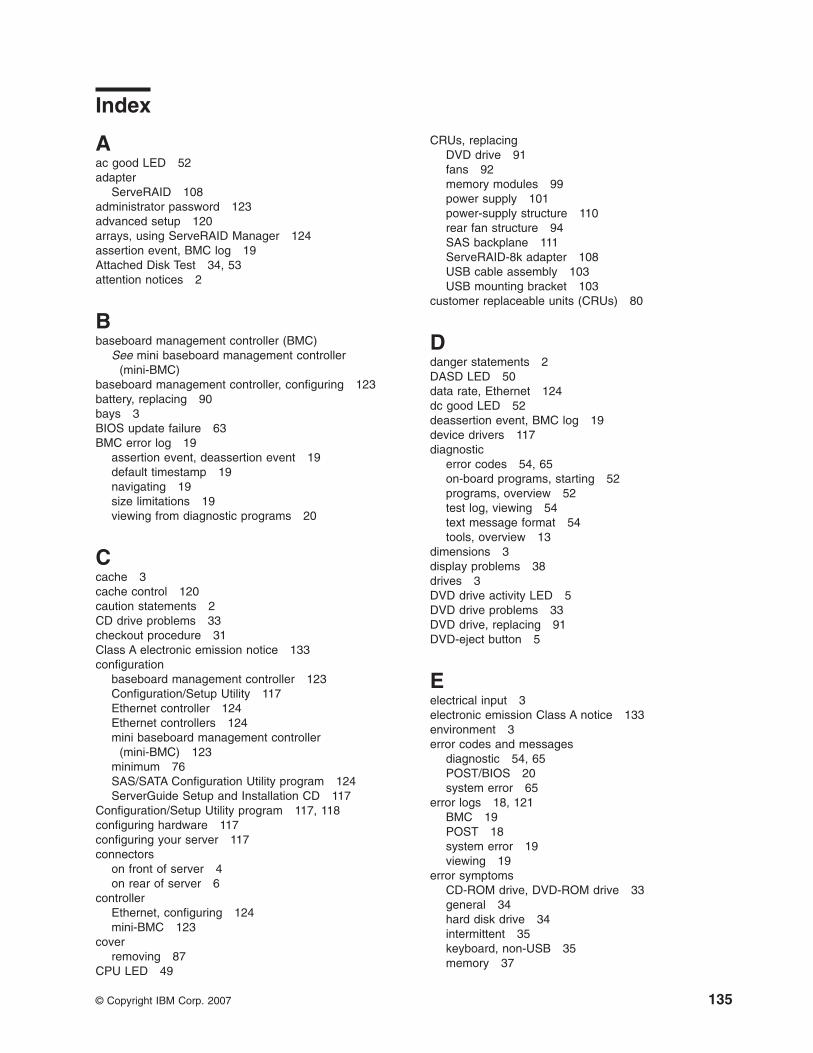
Index
Aac good LED 52
adapterServeRAID 108
administrator password 123
advanced setup 120
arrays, using ServeRAID Manager 124
assertion event, BMC log 19
Attached Disk Test 34, 53
attention notices 2
Bbaseboard management controller (BMC)
See mini baseboard management controller
(mini-BMC)
baseboard management controller, configuring 123
battery, replacing 90
bays 3
BIOS update failure 63
BMC error log 19
assertion event, deassertion event 19
default timestamp 19
navigating 19
size limitations 19
viewing from diagnostic programs 20
Ccache 3
cache control 120
caution statements 2
CD drive problems 33
checkout procedure 31
Class A electronic emission notice 133
configurationbaseboard management controller 123
Configuration/Setup Utility 117
Ethernet controller 124
Ethernet controllers 124
mini baseboard management controller
(mini-BMC) 123
minimum 76
SAS/SATA Configuration Utility program 124
ServerGuide Setup and Installation CD 117
Configuration/Setup Utility program 117, 118
configuring hardware 117
configuring your server 117
connectorson front of server 4
on rear of server 6
controllerEthernet, configuring 124
mini-BMC 123
coverremoving 87
CPU LED 49
CRUs, replacingDVD drive 91
fans 92
memory modules 99
power supply 101
power-supply structure 110
rear fan structure 94
SAS backplane 111
ServeRAID-8k adapter 108
USB cable assembly 103
USB mounting bracket 103
customer replaceable units (CRUs) 80
Ddanger statements 2
DASD LED 50
data rate, Ethernet 124
dc good LED 52
deassertion event, BMC log 19
device drivers 117
diagnosticerror codes 54, 65
on-board programs, starting 52
programs, overview 52
test log, viewing 54
text message format 54
tools, overview 13
dimensions 3
display problems 38
drives 3
DVD drive activity LED 5
DVD drive problems 33
DVD drive, replacing 91
DVD-eject button 5
Eelectrical input 3
electronic emission Class A notice 133
environment 3
error codes and messagesdiagnostic 54, 65
POST/BIOS 20
system error 65
error logs 18, 121
BMC 19
POST 18
system error 19
viewing 19
error symptomsCD-ROM drive, DVD-ROM drive 33
general 34
hard disk drive 34
intermittent 35
keyboard, non-USB 35
memory 37
© Copyright IBM Corp. 2007 135
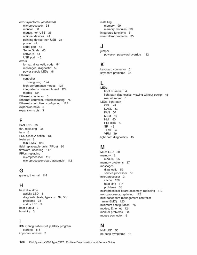
error symptoms (continued)microprocessor 38
monitor 38
mouse, non-USB 35
optional devices 41
pointing device, non-USB 35
power 42
serial port 43
ServerGuide 43
software 44
USB port 45
errorsformat, diagnostic code 54
messages, diagnostic 52
power supply LEDs 51
Ethernetcontroller
configuring 124
high performance modes 124
integrated on system board 124
modes 124
Ethernet connector 6
Ethernet controller, troubleshooting 75
Ethernet controllers, configuring 124
expansion bays 3
expansion slots 3
FFAN LED 50
fan, replacing 92
fans 3
FCC Class A notice 133
features 3
mini-BMC 123
field replaceable units (FRUs) 80
firmware, updating 117
FRUs, replacingmicroprocessor 112
microprocessor-board assembly 112
Ggrease, thermal 114
Hhard disk drive
activity LED 4
diagnostic tests, types of 34, 53
problems 34
status LED 5
heat output 3
humidity 3
IIBM Configuration/Setup Utility program
starting 118
important notices 2
installingmemory 99
memory modules 99
integrated functions 3
intermittent problems 35
Jjumper
power-on password override 122
Kkeyboard connector 6
keyboard problems 35
LLEDs
front of server 4
light path diagnostics, viewing without power 45
rear of server 6
LEDs, light pathCPU 49
DASD 50
FAN 50
MEM 50
NMI 50
PCI BRD 50
SP 49
TEMP 48
VRM 49
light path diagnostics 45
MMEM LED 50
memory 3
module 95
memory problems 37
messagesdiagnostic 52
service processor 65
microprocessor 3
cache 120
heat sink 114
problems 38
microprocessor-board assembly, replacing 112
microprocessor, replacing 112
mini baseboard management controller
(mini-BMC) 123
minimum configuration 76
modes, Ethernet 124
monitor problems 38
mouse connector 6
NNMI LED 50
no-beep symptoms 18
136 IBM System x3500 Type 7977: Problem Determination and Service Guide
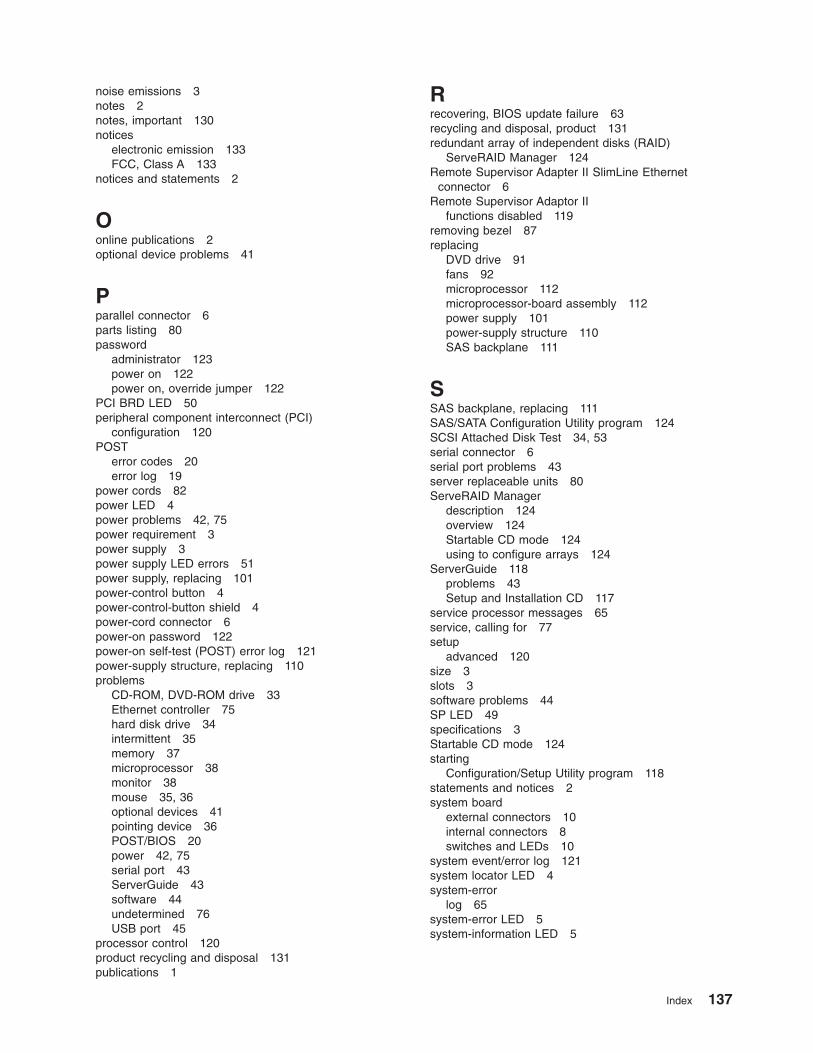
noise emissions 3
notes 2
notes, important 130
noticeselectronic emission 133
FCC, Class A 133
notices and statements 2
Oonline publications 2
optional device problems 41
Pparallel connector 6
parts listing 80
passwordadministrator 123
power on 122
power on, override jumper 122
PCI BRD LED 50
peripheral component interconnect (PCI)configuration 120
POSTerror codes 20
error log 19
power cords 82
power LED 4
power problems 42, 75
power requirement 3
power supply 3
power supply LED errors 51
power supply, replacing 101
power-control button 4
power-control-button shield 4
power-cord connector 6
power-on password 122
power-on self-test (POST) error log 121
power-supply structure, replacing 110
problemsCD-ROM, DVD-ROM drive 33
Ethernet controller 75
hard disk drive 34
intermittent 35
memory 37
microprocessor 38
monitor 38
mouse 35, 36
optional devices 41
pointing device 36
POST/BIOS 20
power 42, 75
serial port 43
ServerGuide 43
software 44
undetermined 76
USB port 45
processor control 120
product recycling and disposal 131
publications 1
Rrecovering, BIOS update failure 63
recycling and disposal, product 131
redundant array of independent disks (RAID)ServeRAID Manager 124
Remote Supervisor Adapter II SlimLine Ethernet
connector 6
Remote Supervisor Adaptor IIfunctions disabled 119
removing bezel 87
replacingDVD drive 91
fans 92
microprocessor 112
microprocessor-board assembly 112
power supply 101
power-supply structure 110
SAS backplane 111
SSAS backplane, replacing 111
SAS/SATA Configuration Utility program 124
SCSI Attached Disk Test 34, 53
serial connector 6
serial port problems 43
server replaceable units 80
ServeRAID Managerdescription 124
overview 124
Startable CD mode 124
using to configure arrays 124
ServerGuide 118
problems 43
Setup and Installation CD 117
service processor messages 65
service, calling for 77
setupadvanced 120
size 3
slots 3
software problems 44
SP LED 49
specifications 3
Startable CD mode 124
startingConfiguration/Setup Utility program 118
statements and notices 2
system boardexternal connectors 10
internal connectors 8
switches and LEDs 10
system event/error log 121
system locator LED 4
system-errorlog 65
system-error LED 5
system-information LED 5
Index 137
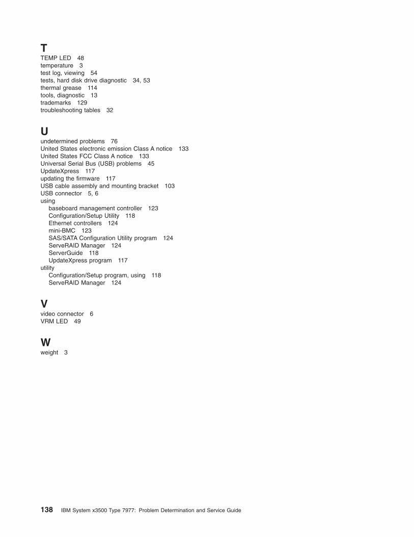
TTEMP LED 48
temperature 3
test log, viewing 54
tests, hard disk drive diagnostic 34, 53
thermal grease 114
tools, diagnostic 13
trademarks 129
troubleshooting tables 32
Uundetermined problems 76
United States electronic emission Class A notice 133
United States FCC Class A notice 133
Universal Serial Bus (USB) problems 45
UpdateXpress 117
updating the firmware 117
USB cable assembly and mounting bracket 103
USB connector 5, 6
usingbaseboard management controller 123
Configuration/Setup Utility 118
Ethernet controllers 124
mini-BMC 123
SAS/SATA Configuration Utility program 124
ServeRAID Manager 124
ServerGuide 118
UpdateXpress program 117
utilityConfiguration/Setup program, using 118
ServeRAID Manager 124
Vvideo connector 6
VRM LED 49
Wweight 3
138 IBM System x3500 Type 7977: Problem Determination and Service Guide

����
Part Number: 42C5010
Printed in USA
(1P) P/N: 42C5010