Embed Size (px)
Citation preview
Problem 7: Contact between a block and a rigid cylinder
ADINA R & D, Inc. 7-1
Problem description A block is pushed onto a rigid cylinder as shown:
All lengths in meters
E =1 106 N/m2�0.1
� = 0.3
0.1
Prescribeddisplacement
Block:
Rigid cylinder,frictionless contact
0.05
Plane strain conditions
We would like to determine the displacements and stresses in the block when the block is pushed down 0.02 m. In this problem solution, we will demonstrate the following topics that have not been presented in previous problems: • Defining a time function • Defining time steps • Defining a contact group, contact surfaces and contact pairs • Using the Previous Solution, Next Solution, Last Solution and First Solution icons • Animating the model response • Plotting results as a function of time • Plotting contact tractions • Creating animation files for the PC (including AVI and GIF formats) We assume that you have worked through problems 1 to 6, or have equivalent experience with the ADINA System. Before you begin Please refer to the Icon Locator Tables chapter of the Primer for the locations of all of the AUI icons. Please refer to the Hints chapter of the Primer for useful hints. This problem can be solved with the 900 nodes version of the ADINA System.
Problem 7: Contact between a block and a rigid cylinder
7-2 ADINA Primer
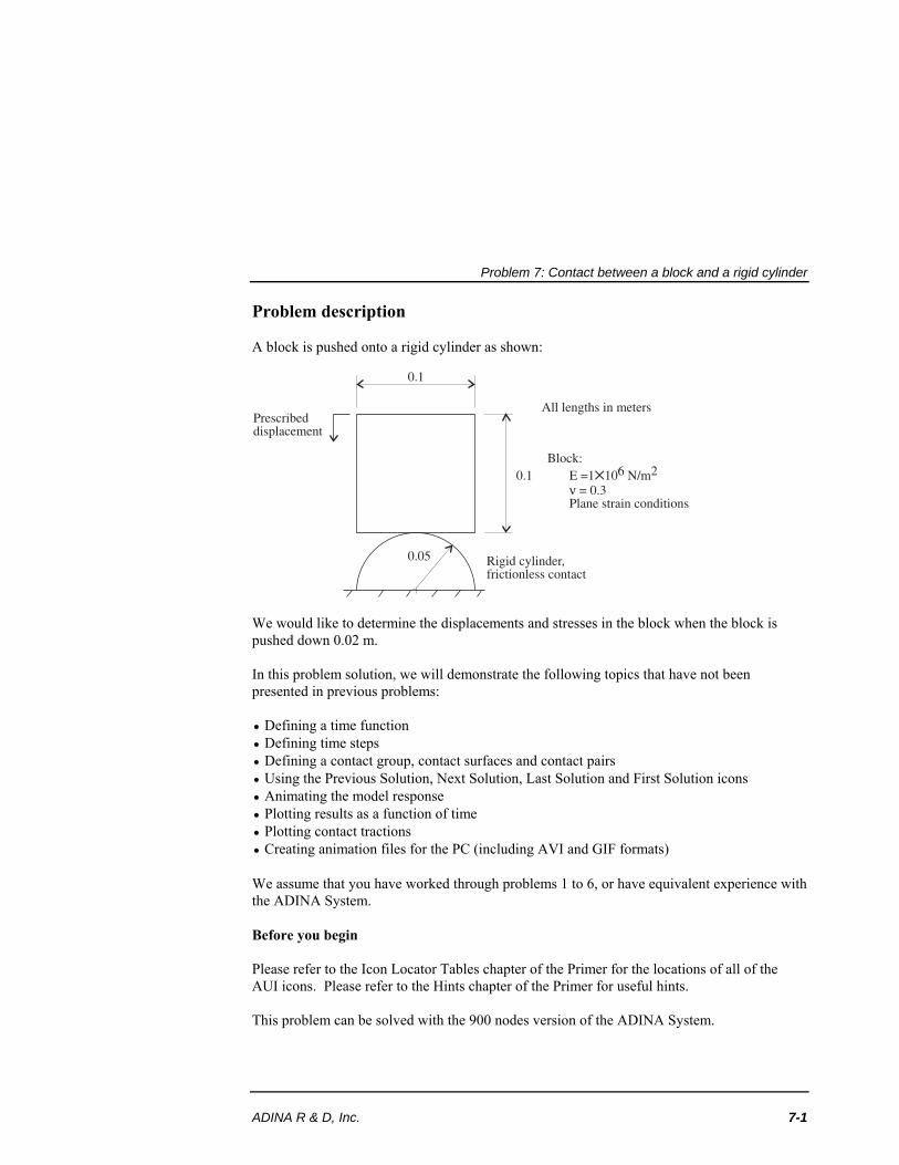
Invoking the AUI and choosing the finite element program Invoke the AUI and set the Program Module drop-down list to ADINA Structures. Defining model control data Problem heading: Choose ControlHeading, enter the heading “Problem 7: Contact between a block and a rigid cylinder” and click OK. Plane for 2D elements: Choose ControlMiscellaneous Options, set the "2D Solid Elements in" field to "XY-Plane, Y-Axisymmetric" and click OK. Defining model geometry Here is a diagram showing the key geometry used in defining this model:
x
P1P2
P3 P4
y
L2
L1
P6 P5
S1
L4
Geometry points: Click the Define Points icon , enter the following information into the X1, X2 columns of the table (you can leave the X3 column blank), then click OK.
Point # X1 X2 1 2 3 4 5 6
0.05 -0.05 -0.05 0.05 0.05
-0.05
0.1 0.1 0.0 0.0
-0.05 -0.05
Problem 7: Contact between a block and a rigid cylinder
ADINA R & D, Inc. 7-3
Click the Point Labels icon to display the point numbers.
Geometry line: Click the Define Lines icon and add line number 1. Set the Type to Arc, set 'Defined by' to ‘P1, P2, P3, Angle’, set 'Starting Point, P1' to 5, 'End Point, P2' to 6, 'In-Plane Point, P3' to 1, 'Included Angle' to 180, and click OK.
Click the Line/Edge Labels icon to display the line number.
Geometry surface: Click the Define Surfaces icon . Add surface number 1, set the Type to Vertex if necessary, set Point 1 to 1, Point 2 to 2, Point 3 to 3, Point 4 to 4 and click OK.
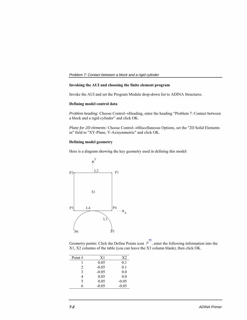
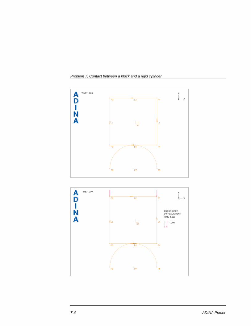
Click the Surface/Face Labels icon to display the surface number. The graphics window should look something like the top figure on the next page. Defining and applying loads
Click the Apply Load icon , set the Load Type to Displacement and click the Define... button to the right of the Load Number field. In the Displacement dialog box, add displacement 1, set the X Translation to 0, the Y Translation to -1 and click OK. In the Apply Load dialog box, set the “Apply to” field to Line, and, in the first row of the table, set the Line # to 2. Click OK to close the Apply Load dialog box.
Click the Load Plot icon . The graphics window should look something like the bottom figure on the next page. Defining the material
Click the Manage Materials icon and click the Elastic Isotropic button. In the Define Isotropic Linear Elastic Material dialog box, add material 1, set the Young's Modulus to 1E6, the Poisson's ratio to 0.3 and click OK. Click Close to close the Manage Material Definitions dialog box.
Problem 7: Contact between a block and a rigid cylinder
7-4 ADINA Primer
P1P2
P3 P4
P5P6 P7
L1
L2
L3
L4
L5S1
TIME 1.000
Z X
Y
P1P2
P3 P4
P5P6 P7
L1
L2
L3
L4
L5S1
TIME 1.000
PRESCRIBEDDISPLACEMENT
TIME 1.000
1.000
Z X
Y
Problem 7: Contact between a block and a rigid cylinder
ADINA R & D, Inc. 7-5
Defining the contact surfaces
Contact group: Click the Contact Groups icon , add contact group 1 and click OK.
Contact surfaces: Click the Define Contact Surfaces icon , add contact surface number 1, set the Line number to 1 in the first row of the table and click Save. Now add contact surface number 2, set the Line number to 4 in the first row of the table and click OK to close the dialog box.
Contact pair: Click the Define Contact Pairs icon , add contact pair number 1, set the Target Surface to 1, the Contactor Surface to 2 and click OK. Defining the elements
Element group: Click the Element Groups icon , add group number 1, set the Type to 2-D Solid, the Element Sub-Type to Plane Strain and click OK. Subdivision data: We will use a 55 mesh for the solution. Click the Subdivide Surfaces icon
, set the “Number of Subdivisions” for both u and v to 5 and click OK.
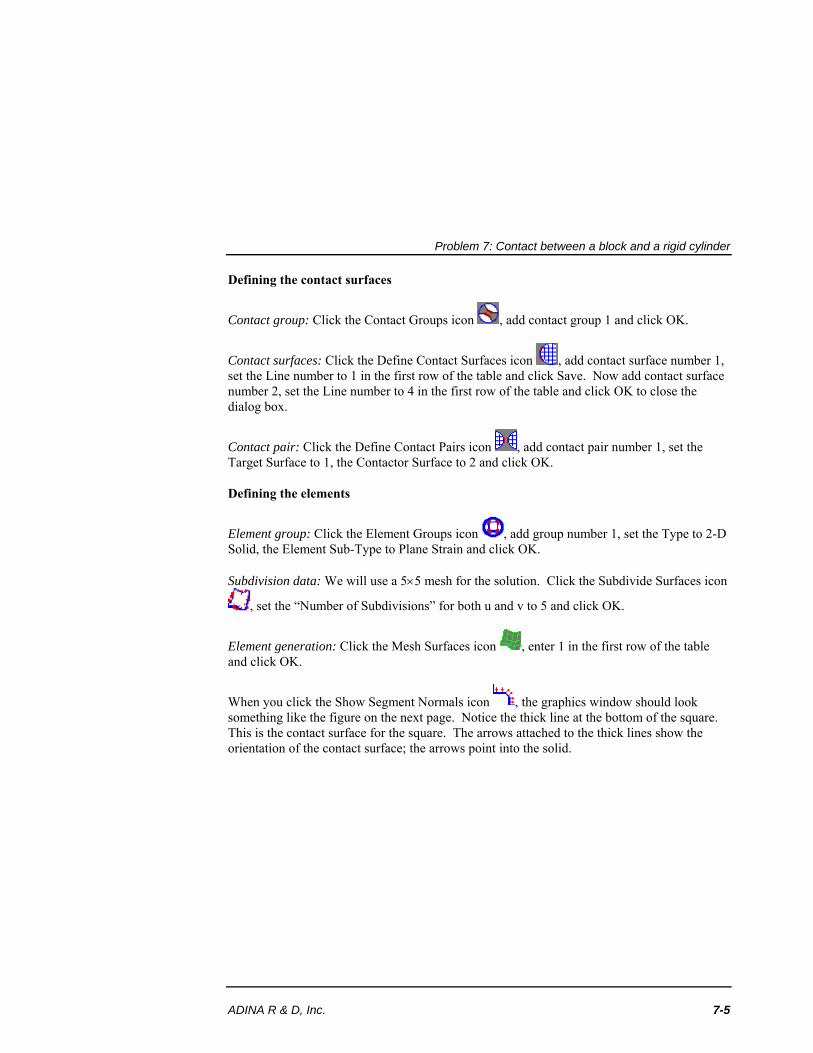
Element generation: Click the Mesh Surfaces icon , enter 1 in the first row of the table and click OK.
When you click the Show Segment Normals icon , the graphics window should look something like the figure on the next page. Notice the thick line at the bottom of the square. This is the contact surface for the square. The arrows attached to the thick lines show the orientation of the contact surface; the arrows point into the solid.
Problem 7: Contact between a block and a rigid cylinder
7-6 ADINA Primer
P1P2
P3 P4
P5P6 P7
L1
L2
L3
L4
L5S1
TIME 1.000
PRESCRIBEDDISPLACEMENT
TIME 1.000
1.000
Z X
Y
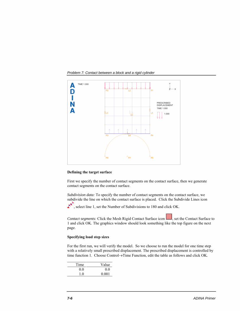
Defining the target surface First we specify the number of contact segments on the contact surface, then we generate contact segments on the contact surface. Subdivision data: To specify the number of contact segments on the contact surface, we subdivide the line on which the contact surface is placed. Click the Subdivide Lines icon
, select line 1, set the Number of Subdivisions to 180 and click OK.
Contact segments: Click the Mesh Rigid Contact Surface icon , set the Contact Surface to 1 and click OK. The graphics window should look something like the top figure on the next page. Specifying load step sizes For the first run, we will verify the model. So we choose to run the model for one time step with a relatively small prescribed displacement. The prescribed displacement is controlled by time function 1. Choose ControlTime Function, edit the table as follows and click OK.
Time Value 0.0 1.0
0.0 0.001
Problem 7: Contact between a block and a rigid cylinder
ADINA R & D, Inc. 7-7
P1P2
P3 P4
P5P6 P7
L1
L2
L3
L4
L5S1
TIME 1.000
PRESCRIBEDDISPLACEMENT
TIME 1.000
1.000
Z X
Y
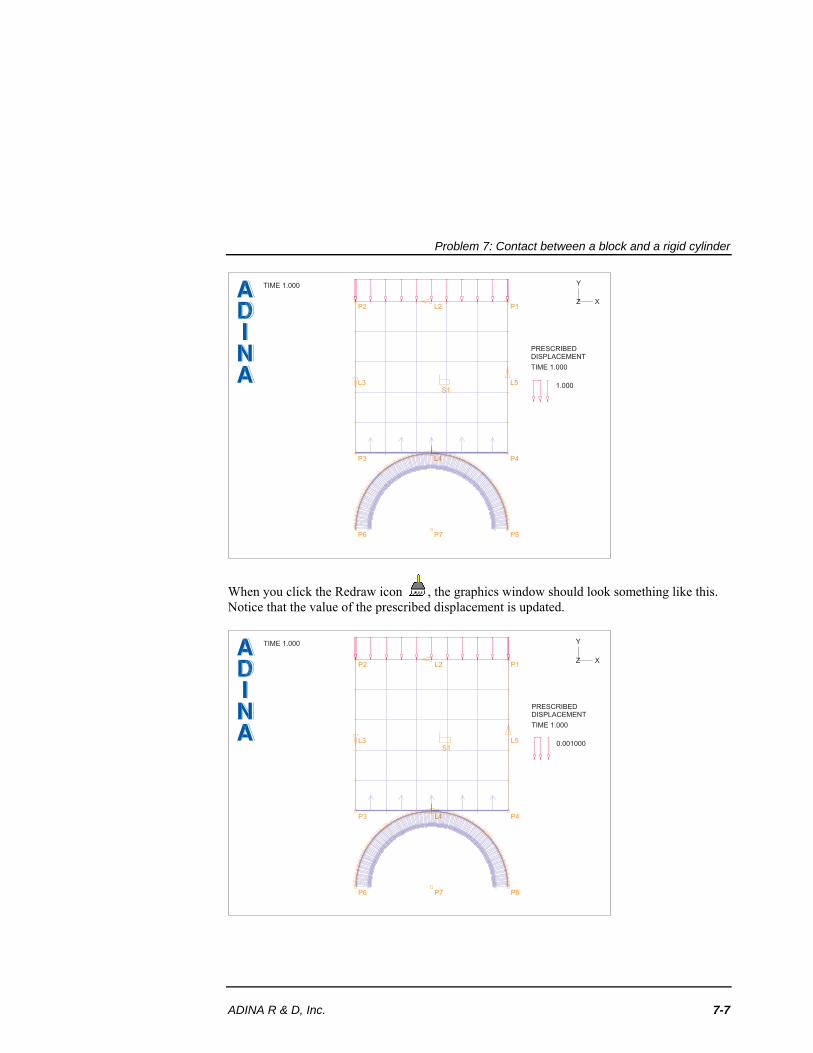
When you click the Redraw icon , the graphics window should look something like this. Notice that the value of the prescribed displacement is updated.
P1P2
P3 P4
P5P6 P7
L1
L2
L3
L4
L5S1
TIME 1.000
PRESCRIBEDDISPLACEMENT
TIME 1.000
0.001000
Z X
Y
Problem 7: Contact between a block and a rigid cylinder
7-8 ADINA Primer
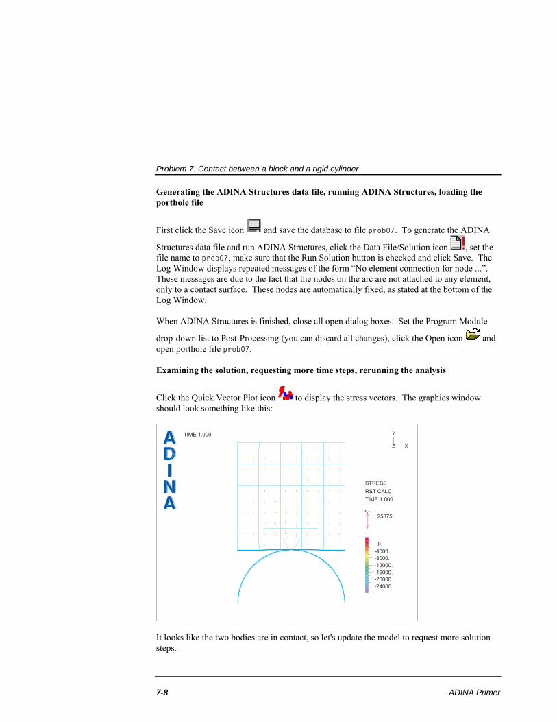
Generating the ADINA Structures data file, running ADINA Structures, loading the porthole file
First click the Save icon and save the database to file prob07. To generate the ADINA
Structures data file and run ADINA Structures, click the Data File/Solution icon , set the file name to prob07, make sure that the Run Solution button is checked and click Save. The Log Window displays repeated messages of the form “No element connection for node ...”. These messages are due to the fact that the nodes on the arc are not attached to any element, only to a contact surface. These nodes are automatically fixed, as stated at the bottom of the Log Window. When ADINA Structures is finished, close all open dialog boxes. Set the Program Module
drop-down list to Post-Processing (you can discard all changes), click the Open icon and open porthole file prob07. Examining the solution, requesting more time steps, rerunning the analysis
Click the Quick Vector Plot icon to display the stress vectors. The graphics window should look something like this:
TIME 1.000
STRESS
RST CALC
TIME 1.000
+ -
25375.
0.
-4000.
-8000.
-12000.
-16000.
-20000.
-24000.
Z X
Y
It looks like the two bodies are in contact, so let's update the model to request more solution steps.
Problem 7: Contact between a block and a rigid cylinder
ADINA R & D, Inc. 7-9
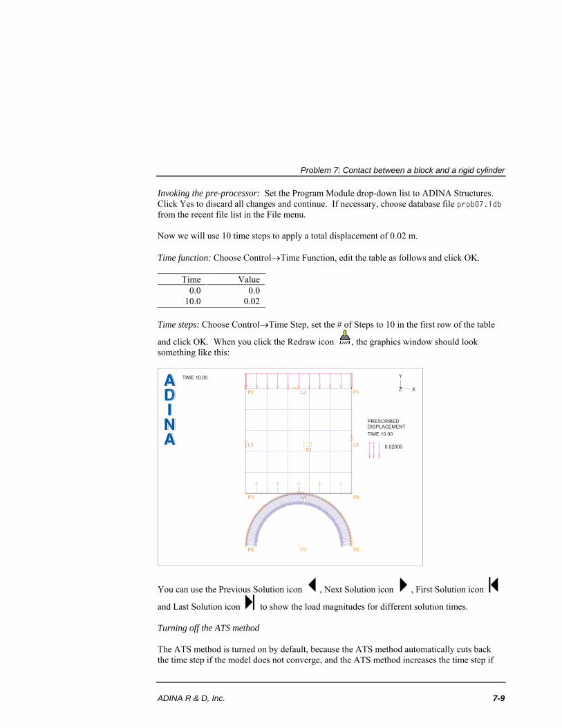
Invoking the pre-processor: Set the Program Module drop-down list to ADINA Structures. Click Yes to discard all changes and continue. If necessary, choose database file prob07.idb from the recent file list in the File menu. Now we will use 10 time steps to apply a total displacement of 0.02 m. Time function: Choose ControlTime Function, edit the table as follows and click OK.
Time Value 0.0
10.0 0.0
0.02 Time steps: Choose ControlTime Step, set the # of Steps to 10 in the first row of the table
and click OK. When you click the Redraw icon , the graphics window should look something like this:
P1P2
P3 P4
P5P6 P7
L1
L2
L3
L4
L5S1
TIME 10.00
PRESCRIBEDDISPLACEMENT
TIME 10.00
0.02000
Z X
Y
You can use the Previous Solution icon , Next Solution icon , First Solution icon
and Last Solution icon to show the load magnitudes for different solution times. Turning off the ATS method The ATS method is turned on by default, because the ATS method automatically cuts back the time step if the model does not converge, and the ATS method increases the time step if
Problem 7: Contact between a block and a rigid cylinder
7-10 ADINA Primer
the model converges quickly. These ATS features are frequently used in practical analysis. However, in this simple problem, we don't need the ATS method. Click the Analysis Options
icon ,. set the Automatic Time Stepping Scheme to None and click OK.
Rerunning ADINA Structures: Click the Save icon to save the current database file. Now
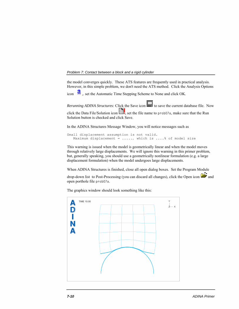
click the Data File/Solution icon , set the file name to prob07a, make sure that the Run Solution button is checked and click Save. In the ADINA Structures Message Window, you will notice messages such as Small displacement assumption is not valid. Maximum displacement = ....., which is ....% of model size This warning is issued when the model is geometrically linear and when the model moves through relatively large displacements. We will ignore this warning in this primer problem, but, generally speaking, you should use a geometrically nonlinear formulation (e.g. a large displacement formulation) when the model undergoes large displacements. When ADINA Structures is finished, close all open dialog boxes. Set the Program Module
drop-down list to Post-Processing (you can discard all changes), click the Open icon and open porthole file prob07a. The graphics window should look something like this:
TIME 10.00
Z X
Y
Problem 7: Contact between a block and a rigid cylinder
ADINA R & D, Inc. 7-11
Animating the results
To create a movie of the mesh deformations, click the Movie Load Step icon . The AUI updates the finite element mesh plot for each solution step, displays it and stores each resulting plot into a frame of movie number 1. To animate the movie once, click the Animate
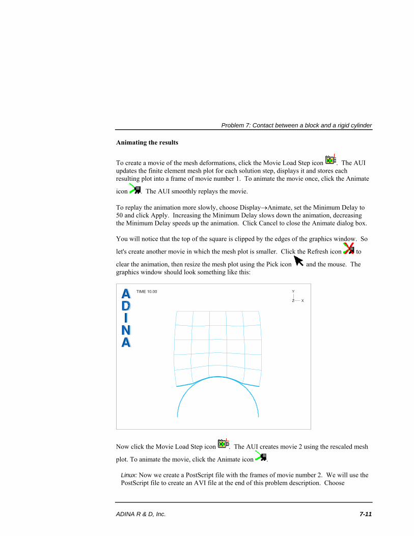
icon . The AUI smoothly replays the movie. To replay the animation more slowly, choose DisplayAnimate, set the Minimum Delay to 50 and click Apply. Increasing the Minimum Delay slows down the animation, decreasing the Minimum Delay speeds up the animation. Click Cancel to close the Animate dialog box. You will notice that the top of the square is clipped by the edges of the graphics window. So
let's create another movie in which the mesh plot is smaller. Click the Refresh icon to
clear the animation, then resize the mesh plot using the Pick icon and the mouse. The graphics window should look something like this:
TIME 10.00
Z X
Y
Now click the Movie Load Step icon . The AUI creates movie 2 using the rescaled mesh
plot. To animate the movie, click the Animate icon .
Linux: Now we create a PostScript file with the frames of movie number 2. We will use the PostScript file to create an AVI file at the end of this problem description. Choose
Problem 7: Contact between a block and a rigid cylinder
7-12 ADINA Primer
FileSave Movie, make sure that the Movie Number is set to 2, enter file name mov2.ps and click Save.
Next we create an MPEG file of the movie. Click the Save MPEG Movie icon . , enter file name mov2 and click Save.
Windows: Now we create an AVI file of movie number 2. Click the Save Movie icon , enter file name mov2, check the 'Play Movie After Saving' button and click Save. The AUI displays the Windows Media Player after the AUI completes the AVI movie. Choose FileExit to exit the Windows Media Player.
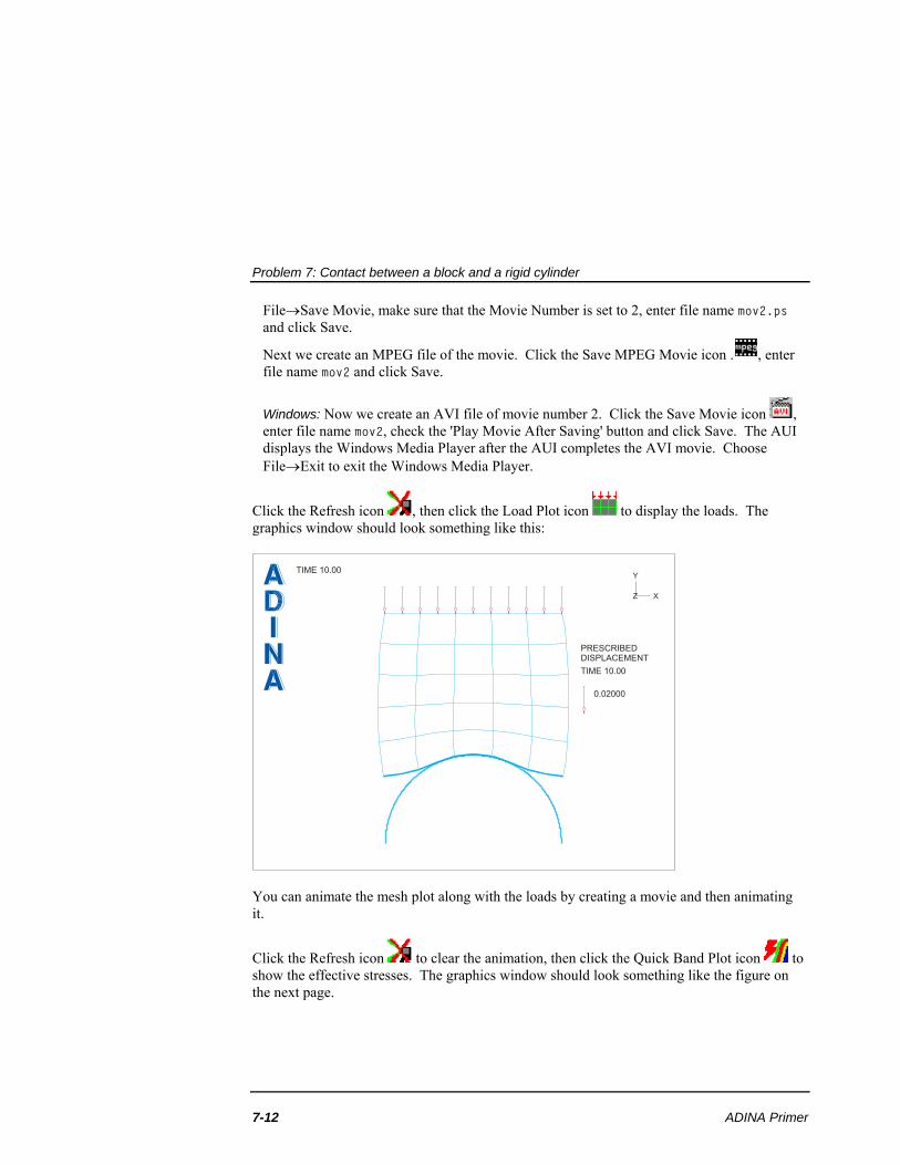
Click the Refresh icon , then click the Load Plot icon to display the loads. The graphics window should look something like this:
TIME 10.00
PRESCRIBEDDISPLACEMENT
TIME 10.00
0.02000
Z X
Y
You can animate the mesh plot along with the loads by creating a movie and then animating it.
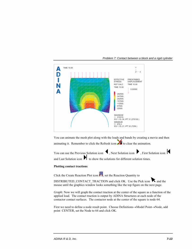
Click the Refresh icon to clear the animation, then click the Quick Band Plot icon to show the effective stresses. The graphics window should look something like the figure on the next page.
Problem 7: Contact between a block and a rigid cylinder
ADINA R & D, Inc. 7-13
TIME 10.00
PRESCRIBEDDISPLACEMENT
TIME 10.00
0.02000
EFFECTIVESTRESS
RST CALC
TIME 10.00
292500.
247500.
202500.
157500.
112500.
67500.
22500.
MAXIMUM310315.
EG 1, EL 24, IPT 31 (276102.)
MINIMUM679.3
EG 1, EL 21, IPT 32 (7256.)
Z X
Y
You can animate the mesh plot along with the loads and bands by creating a movie and then
animating it. Remember to click the Refresh icon to clear the animation.
You can use the Previous Solution icon , Next Solution icon , First Solution icon
and Last Solution icon to show the solutions for different solution times. Plotting contact tractions
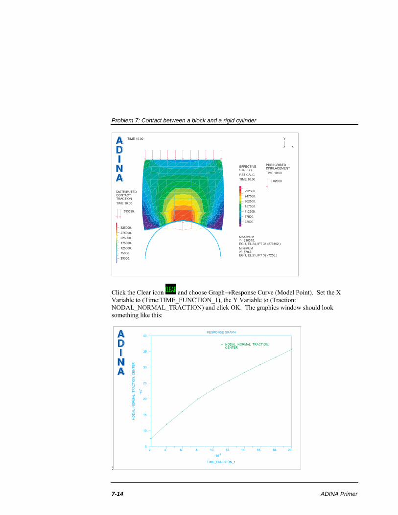
Click the Create Reaction Plot icon , set the Reaction Quantity to
DISTRIBUTED_CONTACT_TRACTION and click OK. Use the Pick icon and the mouse until the graphics window looks something like the top figure on the next page. Graph: Now we will graph the contact traction at the center of the square as a function of the applied load. The contact traction is output by ADINA Structures at each node of the contactor contact surfaces. The contactor node at the center of the square is node 64. First we need to define a node result point. Choose DefinitionsModel PointNode, add point CENTER, set the Node to 64 and click OK.
Problem 7: Contact between a block and a rigid cylinder
7-14 ADINA Primer
TIME 10.00
X
Y
Z
PRESCRIBEDDISPLACEMENT
TIME 10.00
0.02000
EFFECTIVESTRESS
RST CALC
TIME 10.00
292500.
247500.
202500.
157500.
112500.
67500.
22500.
MAXIMUM310315.
EG 1, EL 24, IPT 31 (276102.)
MINIMUM679.3
EG 1, EL 21, IPT 32 (7256.)
DISTRIBUTEDCONTACTTRACTION
TIME 10.00
355599.
325000.
275000.
225000.
175000.
125000.
75000.
25000.
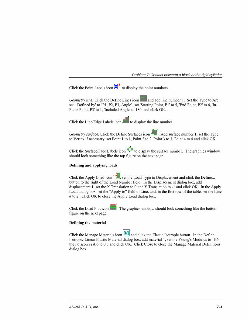
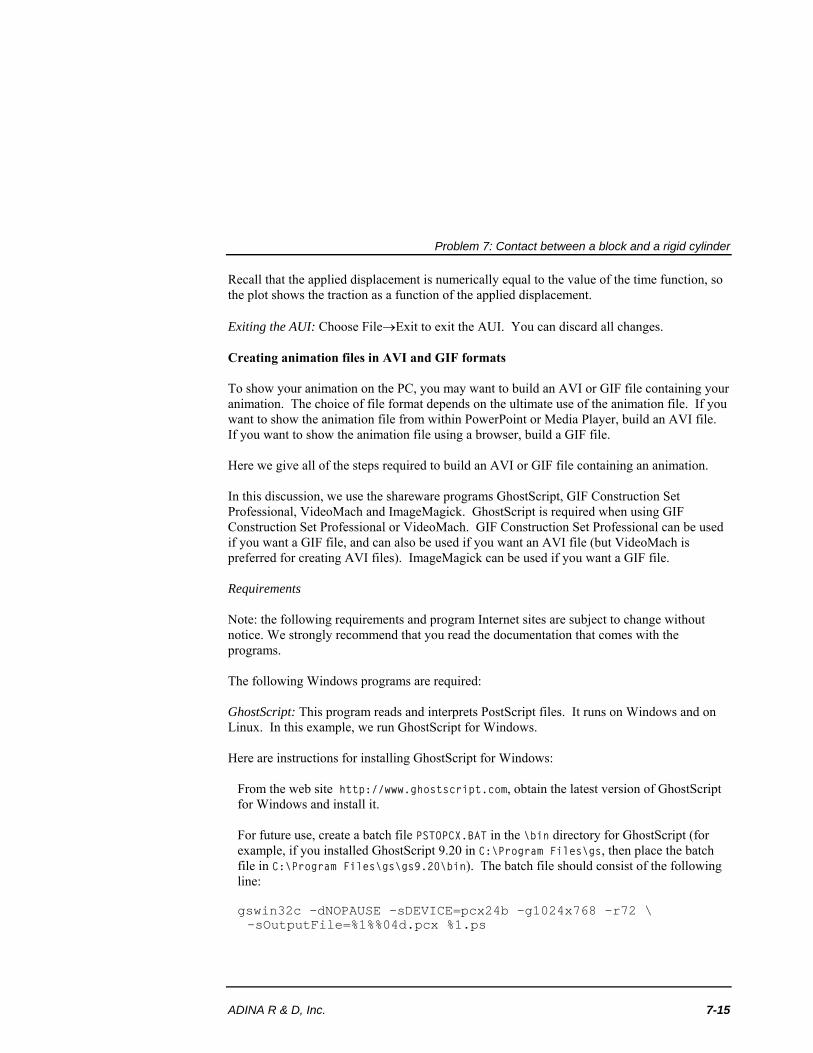
Click the Clear icon and choose GraphResponse Curve (Model Point). Set the X Variable to (Time:TIME_FUNCTION_1), the Y Variable to (Traction: NODAL_NORMAL_TRACTION) and click OK. The graphics window should look something like this:
:
2. 4. 6. 8. 10. 12. 14. 16. 18. 20.
*10-3
5.
10.
15.
20.
25.
30.
35.
40.
*10
4
RESPONSE GRAPH
NODAL_NORMAL_TRACTION,CENTER
TIME_FUNCTION_1
NO
DA
L_
NO
RM
AL
_T
RA
CT
ION
,C
EN
TE
R
Problem 7: Contact between a block and a rigid cylinder
ADINA R & D, Inc. 7-15
Recall that the applied displacement is numerically equal to the value of the time function, so the plot shows the traction as a function of the applied displacement. Exiting the AUI: Choose FileExit to exit the AUI. You can discard all changes. Creating animation files in AVI and GIF formats To show your animation on the PC, you may want to build an AVI or GIF file containing your animation. The choice of file format depends on the ultimate use of the animation file. If you want to show the animation file from within PowerPoint or Media Player, build an AVI file. If you want to show the animation file using a browser, build a GIF file. Here we give all of the steps required to build an AVI or GIF file containing an animation. In this discussion, we use the shareware programs GhostScript, GIF Construction Set Professional, VideoMach and ImageMagick. GhostScript is required when using GIF Construction Set Professional or VideoMach. GIF Construction Set Professional can be used if you want a GIF file, and can also be used if you want an AVI file (but VideoMach is preferred for creating AVI files). ImageMagick can be used if you want a GIF file. Requirements Note: the following requirements and program Internet sites are subject to change without notice. We strongly recommend that you read the documentation that comes with the programs. The following Windows programs are required: GhostScript: This program reads and interprets PostScript files. It runs on Windows and on Linux. In this example, we run GhostScript for Windows. Here are instructions for installing GhostScript for Windows:
From the web site http://www.ghostscript.com, obtain the latest version of GhostScript for Windows and install it.
For future use, create a batch file PSTOPCX.BAT in the \bin directory for GhostScript (for example, if you installed GhostScript 9.20 in C:\Program Files\gs, then place the batch file in C:\Program Files\gs\gs9.20\bin). The batch file should consist of the following line:
gswin32c -dNOPAUSE -sDEVICE=pcx24b –g1024x768 –r72 \ -sOutputFile=%1%%04d.pcx %1.ps
Problem 7: Contact between a block and a rigid cylinder
7-16 ADINA Primer
The \ indicates that the second line is a continuation line. When you create the batch file, omit the \ and put both lines on the same line of the batch file.
(If you want to create an animation with a different size, use different values for the –g and –r parameters, as follows:
-g gx x gy, where gx and gy are the dimensions of the animation, in pixels -r r, where r = (72/1024) gx
GIF Construction Set Professional: GIF Construction Set Professional is a Windows based program. GIF Construction Set Professional can be obtained from the web site http://www.mindworkshop.com/alchemy1.html. We strongly recommend that you install it according to the instructions given at that site. We also recommend that you register your copy of GIF Construction Set Professional. The instructions given here are based on GIF Construction Set Professional version 7.0a, revision 2. VideoMach: VideoMach is a Windows based program. VideoMach can be obtained from the web site http://gromada.com/videomach. We strongly recommend that you install it according to the instructions given at that site. We also recommend that you register your copy of VideoMach. We also suggest that you download and install the program Imagen from the same site. The instructions given here are based on VideoMach 5.15.1 and Imagen 3.1.2. ImageMagick: ImageMagick runs on either Windows or Linux. It can be used to convert PostScript files directly to GIF or AVI files. ImageMagick can be obtained from the web site http://www.imagemagick.org. We strongly recommend that you install it according to the instructions given at that site. The instructions given here are based on ImageMagick for Windows, version 7.0.4-3-Q16. Creating PCX files of the animation frames using GhostScript You should have PostScript file mov2.ps, which you created earlier in this problem. 1) Move file mov2.ps to the PC on which GhostScript is installed, into the bin directory for GhostScript (example: C:\Program Files\gs\gs9.20\bin). Note: mov2.ps is a text file, so you can use an ASCII (text) file transfer. 2) Open a Command Prompt window (for example, using Windows-X and choosing Command Prompt) and, in the Command Prompt window, change directory to the bin directory for GhostScript and type
Problem 7: Contact between a block and a rigid cylinder
ADINA R & D, Inc. 7-17
PSTOPCX MOV2 This invokes GhostScript using the batch script that you created. Type quit at the GS> prompt to exit GhostScript. 3) At this point you should have files MOV20001.PCX to MOV20011.PCX in the bin directory for GhostScript. You can delete file MOV2.PS. Close the Command Prompt window. Creating a GIF file and an AVI file using GIF Construction Set Professional You need the .pcx files created by GhostScript before you start. 1) Invoke GIF Construction Set Professional and choose FileAnimation Wizard. 2) Uncheck the Loop button if you do not want to have the GIF file loop indefinitely. 3) Set the animation speed using the Delay field (in 1/100ths of a second). 4) In the left pane of the Animation Wizard dialog box, navigate to the folder that contains the PCX files (in this case, the bin folder for GhostScript). 5) Select all of the PCX files that appear in the middle pane (you can use the Control or Shift keys to select a range of files), then click the Add button. 6) Click Build to complete the animation. When GIF Construction Set is finished, it will display the frames of the animation in a window. 7) To playback the animation, click on the 'Views the current animation' icon (which looks like a pair of glasses). 8) If you do not want to change the speed of the animation, proceed to the next step. Otherwise, to change the speed of the animation, click the 'Selects all the blocks in the current animation' icon (which looks like a blue button), then choose BlockManage. In the Block Management dialog box, make sure that 'Set controls for the selected blocks' is selected, then click Apply. In the Edit Control dialog box, set the animation speed using the Delay field, then click OK twice to close both dialog boxes. 9) To save the animation as a GIF file, choose FileSave as, fill in the dialog box and click Save. 10) To save the animation as an AVI file, choose FilexportExport to Movie, fill in the dialog box and click Save.
Problem 7: Contact between a block and a rigid cylinder
7-18 ADINA Primer
Creating an AVI file using VideoMach You need the .pcx files created by GhostScript before you start. 1) Invoke VideoMach and choose FileOpen Media Files. 2) Navigate to the folder that contains the PCX files (in this case the bin folder for GhostScript), set the 'Files of type' field to PCX, select file mov20001.pcx and click Open. VideoMach displays an Open Images dialog box. Choose “Open image sequence” and click OK. At this point, the lower left window should display the filenames of the 11 PCX files. 3) Choose FileExport Media. Set the Output Mode field to “Video Only”, then set the “Write video to this file” field to, for example, mov2.avi. Click the Video tab and click the Codec Settings… button. In the AVI Video Format dialog box, set the Codec Name to Microsoft Video 1, set Video Quality to 100% and click OK. In the Video tab, in the Frame Rate box, check the “Custom frame rate” button, choose “Keep original number of frames”, enter the desired frame rate (for example, 10) and click Close. (In the Video Codec dialog box, you also might want to set "Key Frame Every" to "1 frame(s)". If you do this, then the slider bar in mplay32.exe will work, see comments for "Playback of an AVI file using Media Player mplay32.exe" below. But the avi file will be much larger.) At this point, the upper-right window should display Video Output File name (file name) Codec Microsoft Video 1 Resolution 1024 x 768 Color depth 15-bit Frames 11 Frame rate 10 fps Duration 00:00:01.100 Raw size 17 MB ..Splitting 2 GB 4) Choose FileExport Media and click Start. VideoMach creates the AVI file and displays a Produced Files Information dialog box. In this dialog box, click the Play icon (which looks like a green arrow) to play the AVI file in Windows Media Player. Creating a GIF file using ImageMagick You do not need the .pcx files created by GhostScript. 1) Move file mov2.ps to the PC on which ImageMagick is installed, into any convenient folder. Note: mov2.ps is a text file, so you can use an ASCII (text) file transfer.
Problem 7: Contact between a block and a rigid cylinder
ADINA R & D, Inc. 7-19
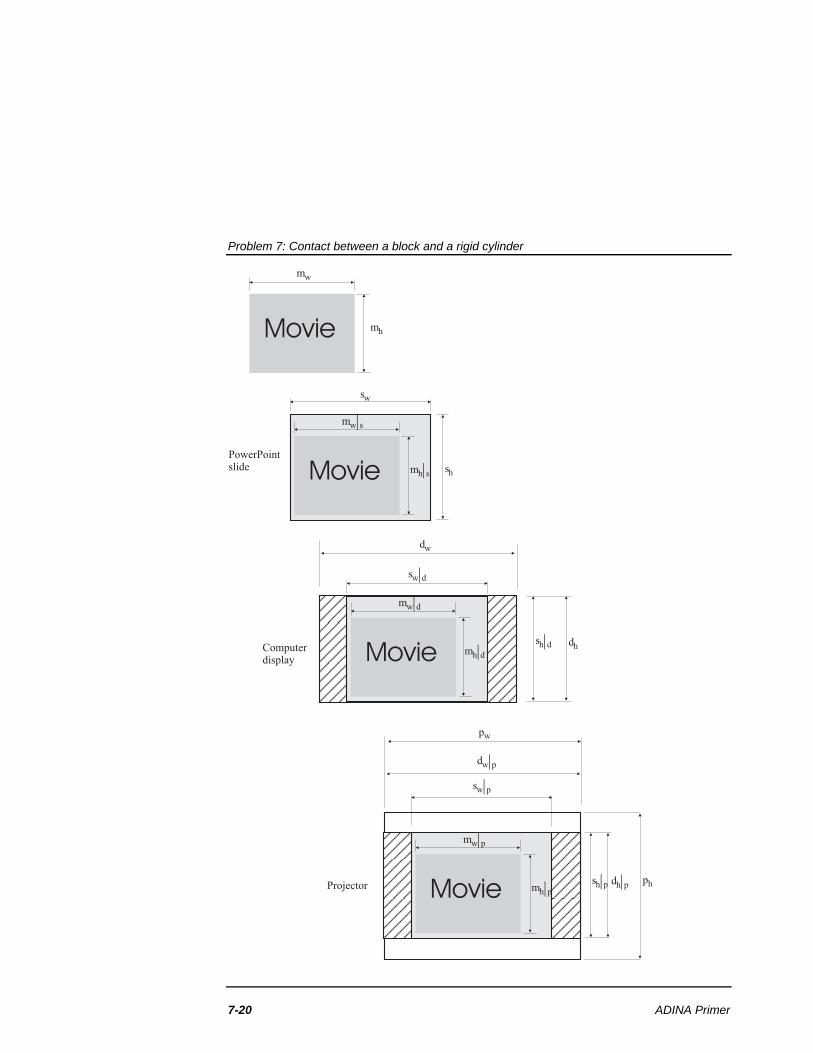
2) Open a Command Prompt window and, in the Command Prompt window, change folder to the folder containing mov2.ps. 3) Type MAGICK MOV2.PS MOV2.GIF Notes for playback of an AVI file using PowerPoint The AVI file produced above can be inserted into a PowerPoint presentation using InsertVideoVideo on My PC. The movie will be inserted into the current slide at a certain size. When you display the movie in your presentation, you may find that the quality of the movie is degraded. This degradation occurs because the size of the movie (in pixels) is adjusted during playback. To prevent the degradation of the quality of the movie, it is necessary to choose the size of the movie within the slide. This size needs to be chosen so that the size of the movie (in pixels) is not adjusted during playback. (In the discussion below, we assume that the size of the slide is measured in inches. If your version of Powerpoint uses cm, substitute cm for inches in the discussion below.) The figure on the next page shows schematically the mappings between the movie, slide, computer display and projector. The dimensions are , movie width and height, in pixelsw hm m
, movie width and height measured on slide, in inchesw hs sm m
, movie width and height measured on display, in pixelsw hd dm m
, movie width and height measured on projector, in pixelsw hp pm m
, slide width and height, in inchesw hs s
, slide width and height measured on display, in pixelsw hd ds s
, slide width and height measured on projector, in pixelsw hp ps s
, display width and height, in pixelsw hd d
, display width and height measured on projector, in pixelsw hp pd d
projector width, in pixelswp , projector height, in pixelshp
Problem 7: Contact between a block and a rigid cylinder
7-20 ADINA Primer
PowerPointslide
Projector
mw
sw
mh
sh
Movie
mw s|
mh s|Movie
Computerdisplay
dw
dh
sw d|
sh d|
mw d|
mh d|Movie
sw p|
sh p| dh p|
dw p|
ph
pw
mw p|
mh p|Movie
Problem 7: Contact between a block and a rigid cylinder
ADINA R & D, Inc. 7-21
The figure shows a correspondence between the slide, display and projector, as follows:
,w ds w h ds hd ds f s s f s , where min ,w h
dsw h
d df
s s
,w pd w h pd hp pd f d d f d , where min ,w h
pdw h
p pf
d d
Therefore ,w ps w h ps hp p
s f s s f s , where ps pd dsf f f
And these correspondences apply for the movie, so that ,w ds w h ds hd s d s
m f m m f m
,w ps w h ps hp s p sm f m m f m
Thus, if we want the movie size on the display to be the same as the original movie size, we can achieve this by setting the movie size on the slide using the formulas
, , ,w hd d w hw hs s
ds ds ds ds
m m m mm m
f f f f
and if we want the movie size on the projector to be the same as the original movie size, we can achieve this by setting the movie size on the slide using the formulas
, , ,w hp p w h
w hs sps ps ps ps
m m m mm m
f f f f
We also need to consider that there is an optimal size for the display and an optimal size for the projector. These optimal sizes are the native resolutions of the display and projector. The size of the display is set within Windows using the Display Properties dialog box, Settings tab. The size of the projector is usually automatically set by Windows to be the same as the size of the display. As a worked example, consider a movie of size 800 x 600 pixels. This movie is to be shown on a computer display with native resolution 1280 x 800 pixels. The PowerPoint slide size is 10 x 7.5 inches. Therefore , (800, 600)w hm m
Problem 7: Contact between a block and a rigid cylinder
7-22 ADINA Primer
, (10, 7.5)w hs s
, (1280, 800)w hd d
1280 800
min , min , 106.6710 7.5
w hds
w h
d df
s s
800 600, , , (7.5,5.62)
106.67 106.67w h
w hs sds ds
m mm m
f f
(Choose Format Picture, click on the Size tab, and under the "Size and rotate text", set the Width to 7.5, then click OK.) Now suppose that the movie is to be shown on a computer projector with native resolution 1024 x 768 pixels. In order to get the projector to use this size, the size of the display needs to be set to the same size. Therefore , (800, 600)w hm m
, (10, 7.5)w hs s
, (1024, 768)w hd d
, (1024, 768)w hp p
1024 768
min , min , 102.410 7.5
w hps ds
w h
d df f
s s
800 600, , , (7.8125,5.859)
102.4 102.4w h
w hs sps ps
m mm m
f f
Note carefully that a projector with native resolution 1024 x 768 pixels, when connected to a display set to 1280 x 800 pixels, might use a size of 1280 x 800 pixels. This will degrade the quality of the projected image. In this case, it is better to set the size of the display to 1024 x 768 pixels, so that the projector uses its native resolution. Notes for playback of an AVI file using Media Player mplay32.exe, for Windows XP users Windows XP includes a media player that works well for display of AVI files. This media player is "mplay32.exe" (not Windows Media Player). Mplay32.exe is not accessible by default from the desktop or Start menu. To access mplay32.exe, use the Search feature to find file mplay32.exe (it might be in \Windows\System32), then right-click mplay32.exe, choose Send To and create a shortcut on the desktop.
Problem 7: Contact between a block and a rigid cylinder
ADINA R & D, Inc. 7-23
Then click on the mplay32.exe icon and open an AVI file. You can play the file as usual by clicking the Play icon. One very useful feature is the slider bar. You can slide the bar left and right and the display will smoothly update, under one condition: the keyframe saving interval in the AVI file must be 1, in other words every frame in the AVI file must be a keyframe. VideoMach can create AVI files in which every frame is a keyframe, see above. Notes for Apple users The Applescript program "sequimago" can be used to take a series of images and convert them into a movie file.

Problem 7: Contact between a block and a rigid cylinder
7-24 ADINA Primer
This page intentionally left blank.