Embed Size (px)
DESCRIPTION
probe
Citation preview
For Reference Only – See Document #141194 Specifications and Ordering Information Page 1 of 29
Specifications and Ordering Information 3300 XL 8 mm Proximity Transducer System
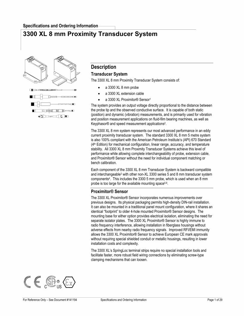
Description Transducer System The 3300 XL 8 mm Proximity Transducer System consists of:
• a 3300 XL 8 mm probe • a 3300 XL extension cable • a 3300 XL Proximitor® Sensor1
The system provides an output voltage directly proportional to the distance between the probe tip and the observed conductive surface. It is capable of both static (position) and dynamic (vibration) measurements, and is primarily used for vibration and position measurement applications on fluid-film bearing machines, as well as Keyphasor® and speed measurement applications2.
The 3300 XL 8 mm system represents our most advanced performance in an eddy current proximity transducer system. The standard 3300 XL 8 mm 5 metre system is also 100% compliant with the American Petroleum Institute’s (API) 670 Standard (4th Edition) for mechanical configuration, linear range, accuracy, and temperature stability. All 3300 XL 8 mm Proximity Transducer Systems achieve this level of performance while allowing complete interchangeability of probe, extension cable, and Proximitor® Sensor without the need for individual component matching or bench calibration.
Each component of the 3300 XL 8 mm Transducer System is backward compatible and interchangeable3 with other non-XL 3300 series 5 and 8 mm transducer system components4. This includes the 3300 5 mm probe, which is used when an 8 mm probe is too large for the available mounting space5,6.
Proximitor® Sensor The 3300 XL Proximitor® Sensor incorporates numerous improvements over previous designs. Its physical packaging permits high-density DIN-rail installation. It can also be mounted in a traditional panel mount configuration, where it shares an identical “footprint” to older 4-hole mounted Proximitor® Sensor designs. The mounting base for either option provides electrical isolation, eliminating the need for separate isolator plates. The 3300 XL Proximitor® Sensor is highly immune to radio frequency interference, allowing installation in fiberglass housings without adverse effects from nearby radio frequency signals. Improved RFI/EMI immunity allows the 3300 XL Proximitor® Sensor to achieve European CE mark approvals without requiring special shielded conduit or metallic housings, resulting in lower installation costs and complexity.
The 3300 XL’s SpringLoc terminal strips require no special installation tools and facilitate faster, more robust field wiring connections by eliminating screw-type clamping mechanisms that can loosen.
For Reference Only – See Document #141194 Specifications and Ordering Information Page 2 of 29
Proximity Probe and Extension Cable The 3300 XL probe and extension cable also reflect improvements over previous designs. A patented TipLoc™ molding method provides a more robust bond between the probe tip and the probe body. The probe’s cable is more securely attached as well, incorporating a patented CableLoc™ design that provides 330 N (75 lbf) pull strength where the probe cable attaches to the probe tip.
3300 XL 8 mm Probes and Extension Cables can also be ordered with an optional FluidLoc® cable option. This option prevents oil and other liquids from leaking out of the machine through the cable’s interior.
Connectors The 3300 XL probe, extension cable, and Proximitor® Sensor have corrosion-resistant, gold-plated ClickLoc™ connectors. These connectors require only finger-tight torque (connectors will "click"), and the specially engineered locking mechanism prevents the connectors from loosening. They do not require any special tools for installation or removal. 3300 XL 8 mm Probes and Extension Cables can also be ordered with connector protectors already installed. Connector protectors can also be supplied separately for installation in the field (such as when the cable must be run through restrictive conduit). Connector protectors are recommended for all installations and provide increased environmental protection7.
Extended Temperature Range Applications An Extended Temperature Range (ETR) Probe and Extension Cable are available for applications where either the probe lead or extension cable may exceed the 177 °C (350 °F) temperature specification. The Extended Temperature Range Probe has an extended temperature rating for up to 260 °C (500 °F) for the probe lead and connector. The probe tip must remain below 177 °C (350 °F). The Extended Temperature Range Extension Cable is also rated for up to 260 °C (500 °F). Both the ETR probe and cable are compatible with standard temperature probes and cables. For example, you can utilize an ETR probe with the 330130 extension cable. The ETR system uses the standard 3300 XL Proximitor Sensor. When using any ETR component as part of your system, the accuracy is limited to the accuracy of the ETR system.
Notes: 1. Proximitor® Sensors are supplied by default
from the factory calibrated to AISI 4140 steel. Calibration to other target materials is available upon request.
2. Consult Bently Nevada Applications Note, Considerations when using Eddy Current Proximity Probes for Overspeed Protection Applications, when considering this transducer
system for tachometer or overspeed measurements.
3. 3300 XL 8 mm components are both electrically and physically interchangeable with non-XL 3300 5 and 8 mm components. Although the packaging of the 3300 XL Proximitor® Sensor differs from its predecessor, it is designed to fit in the same 4-hole mounting pattern when used with the 4-hole mounting base, and will fit within the same mounting space specifications (when minimum permissible cable bend radius is observed).
4. When XL and non-XL 3300-series 5 and 8 mm system components are mixed, system performance is limited to the specifications for the non-XL 3300 5 and 8 mm Transducer System.
5. The 3300-series 5 mm probe (refer to Specifications and Ordering Information p/n 141605-01) uses smaller physical packaging, but does not permit reduced sideview clearances or tip-to-tip spacing requirements compared to an 8 mm probe. It is used when physical (not electrical) constraints preclude the use of an 8 mm probe. When narrow sideview probes are required, use the 3300 NSv™ Proximity Transducer System (refer to Specifications and Ordering Information p/n 147385-01).
6. 8 mm probes provide a thicker encapsulation of the probe coil in the molded PPS plastic probe tip. This results in a more rugged probe. The larger diameter of the probe body also provides a stronger, more robust case. Bently Nevada recommends the use of 8 mm probes when possible to provide optimal robustness against physical abuse.
7. Silicone tape is also provided with each 3300 XL extension cable and can be used instead of connector protectors. Silicone tape is not recommended in applications where the probe-to-extension cable connection will be exposed to turbine oil.
Specifications Unless otherwise noted, the following specifications are for a 3300 XL 8 mm Proximitor® Sensor, extension cable and 8 mm probe between +18 °C and +27 °C (+64 °F to +80 °F), with a -24 Vdc power supply, a 10 kilo Ω load, an AISI 4140 steel target, and a probe gapped at 1.27 mm (50 mils). Performance characteristics are applicable for systems that consist solely of 3300 XL 8 mm components. The system accuracy and interchangeability specifications do not apply when using a transducer system calibrated to any target other than a Bently Nevada AISI 4140 steel target.
For Reference Only – See Document #141194 Specifications and Ordering Information Page 3 of 29
Electrical Proximitor® Sensor Input:
Accepts one noncontacting 3300-series 5 mm, 3300 8 mm or 3300 XL 8 mm Proximity Probe and Extension Cable.
Power: Requires -17.5 Vdc to -26 Vdc without barriers at 12 mA maximum consumption, -23 Vdc to -26 Vdc with barriers. Operation at a more positive voltage than -23.5 Vdc can result in reduced linear range.
Supply Sensitivity:
Less than 2 mV change in output voltage per volt change in input voltage.
Output resistance:
50 Ω
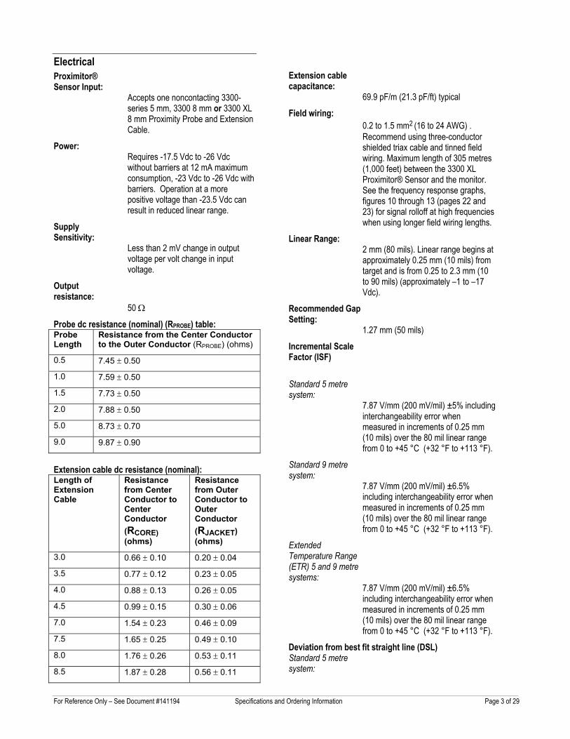
Probe dc resistance (nominal) (RPROBE) table: Probe Length
Resistance from the Center Conductor to the Outer Conductor (RPROBE) (ohms)
0.5 7.45 ± 0.50
1.0 7.59 ± 0.50
1.5 7.73 ± 0.50
2.0 7.88 ± 0.50
5.0 8.73 ± 0.70
9.0 9.87 ± 0.90
Extension cable dc resistance (nominal): Length of Extension Cable
Resistance from Center Conductor to Center Conductor (RCORE) (ohms)
Resistance from Outer Conductor to Outer Conductor (RJACKET) (ohms)
3.0 0.66 ± 0.10 0.20 ± 0.04
3.5 0.77 ± 0.12 0.23 ± 0.05
4.0 0.88 ± 0.13 0.26 ± 0.05
4.5 0.99 ± 0.15 0.30 ± 0.06
7.0 1.54 ± 0.23 0.46 ± 0.09
7.5 1.65 ± 0.25 0.49 ± 0.10
8.0 1.76 ± 0.26 0.53 ± 0.11
8.5 1.87 ± 0.28 0.56 ± 0.11
Extension cable capacitance:
69.9 pF/m (21.3 pF/ft) typical
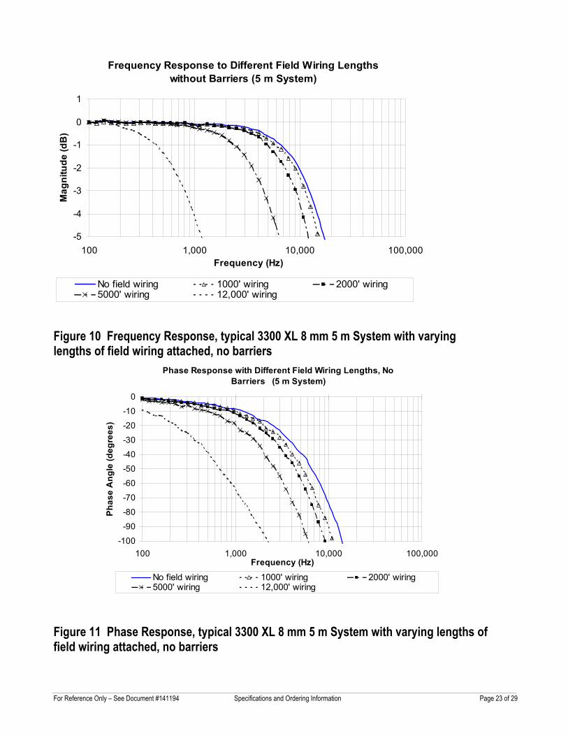
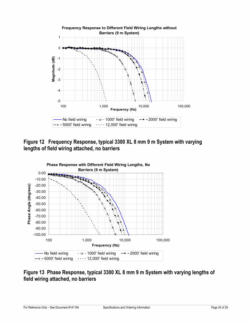
Field wiring: 0.2 to 1.5 mm2 (16 to 24 AWG) . Recommend using three-conductor shielded triax cable and tinned field wiring. Maximum length of 305 metres (1,000 feet) between the 3300 XL Proximitor® Sensor and the monitor. See the frequency response graphs, figures 10 through 13 (pages 22 and 23) for signal rolloff at high frequencies when using longer field wiring lengths.
Linear Range: 2 mm (80 mils). Linear range begins at approximately 0.25 mm (10 mils) from target and is from 0.25 to 2.3 mm (10 to 90 mils) (approximately –1 to –17 Vdc).
Recommended Gap Setting:
1.27 mm (50 mils)
Incremental Scale Factor (ISF)
Standard 5 metre system:
7.87 V/mm (200 mV/mil) ±5% including interchangeability error when measured in increments of 0.25 mm (10 mils) over the 80 mil linear range from 0 to +45 °C (+32 °F to +113 °F).
Standard 9 metre system:
7.87 V/mm (200 mV/mil) ±6.5% including interchangeability error when measured in increments of 0.25 mm (10 mils) over the 80 mil linear range from 0 to +45 °C (+32 °F to +113 °F).
Extended Temperature Range (ETR) 5 and 9 metre systems:
7.87 V/mm (200 mV/mil) ±6.5% including interchangeability error when measured in increments of 0.25 mm (10 mils) over the 80 mil linear range from 0 to +45 °C (+32 °F to +113 °F).
Deviation from best fit straight line (DSL) Standard 5 metre system:
For Reference Only – See Document #141194 Specifications and Ordering Information Page 4 of 29
Less than ±0.025mm (±1 mil) with components at 0 °C to +45 °C (+32 °F to +113 °F).
Standard 9 metre system:
Less than ±0.038mm (±1.5 mil) with components at 0 °C to +45 °C (+32 °F to +113 °F).
Extended Temperature Range 5 and 9 metre systems:
Less than ±0.038mm (±1.5 mil) with components at 0 °C to +45 °C (+32 °F to +113 °F).
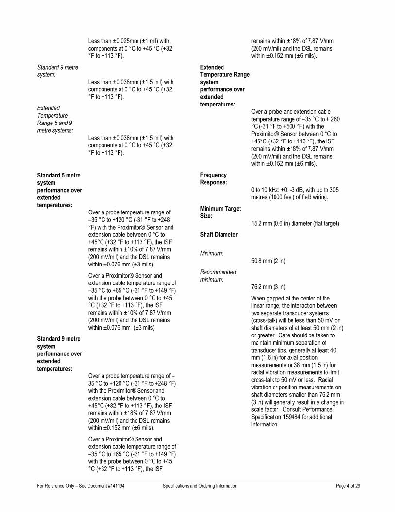
Standard 5 metre system performance over extended temperatures:
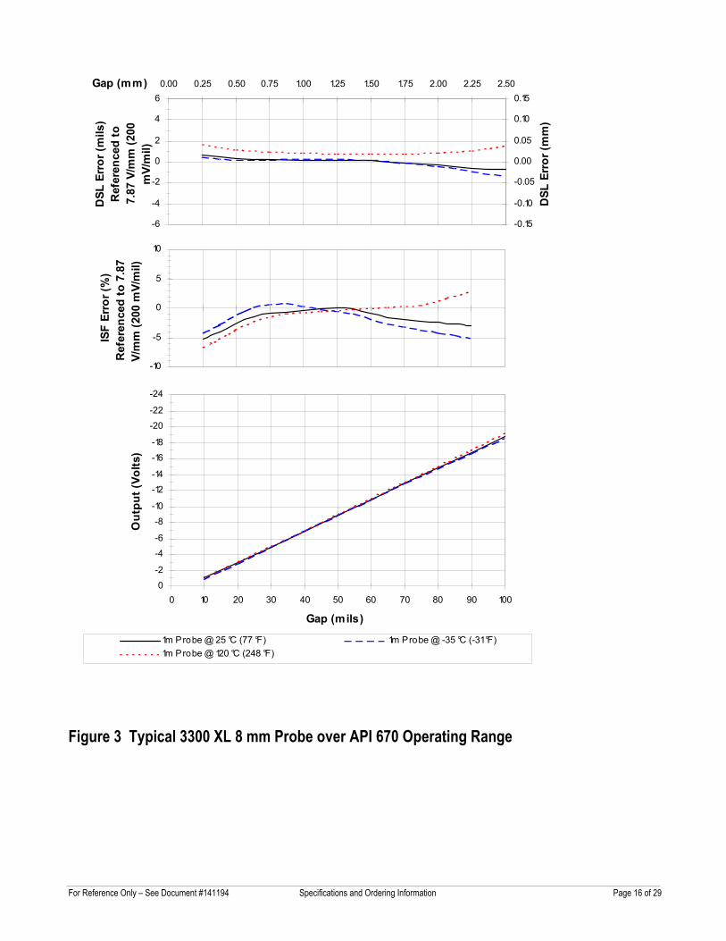
Over a probe temperature range of –35 °C to +120 °C (-31 °F to +248 °F) with the Proximitor® Sensor and extension cable between 0 °C to +45°C (+32 °F to +113 °F), the ISF remains within ±10% of 7.87 V/mm (200 mV/mil) and the DSL remains within ±0.076 mm (±3 mils).
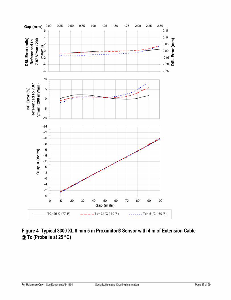
Over a Proximitor® Sensor and extension cable temperature range of –35 °C to +65 °C (-31 °F to +149 °F) with the probe between 0 °C to +45 °C (+32 °F to +113 °F), the ISF remains within ±10% of 7.87 V/mm (200 mV/mil) and the DSL remains within ±0.076 mm (±3 mils).
Standard 9 metre system performance over extended temperatures:
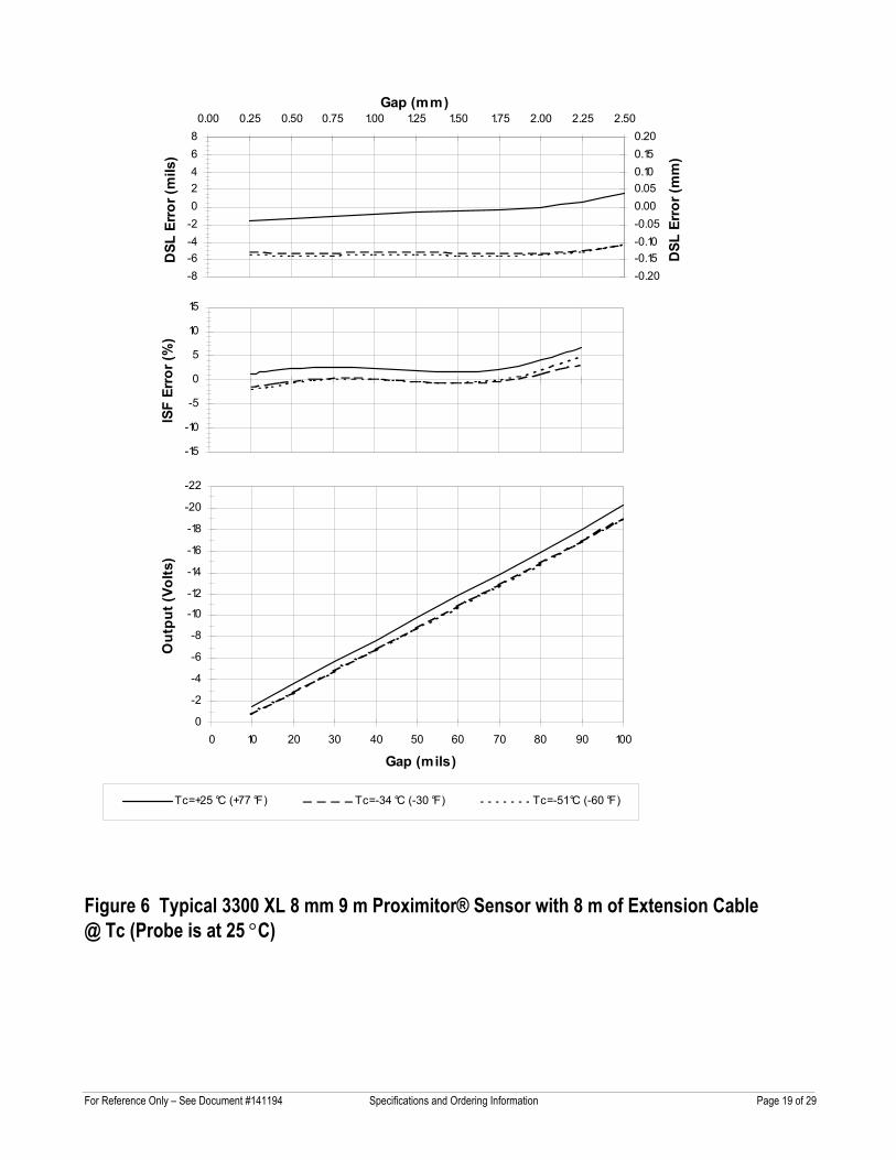
Over a probe temperature range of –35 °C to +120 °C (-31 °F to +248 °F) with the Proximitor® Sensor and extension cable between 0 °C to +45°C (+32 °F to +113 °F), the ISF remains within ±18% of 7.87 V/mm (200 mV/mil) and the DSL remains within ±0.152 mm (±6 mils).
Over a Proximitor® Sensor and extension cable temperature range of –35 °C to +65 °C (-31 °F to +149 °F) with the probe between 0 °C to +45 °C (+32 °F to +113 °F), the ISF
remains within ±18% of 7.87 V/mm (200 mV/mil) and the DSL remains within ±0.152 mm (±6 mils).
Extended Temperature Range system performance over extended temperatures:
Over a probe and extension cable temperature range of –35 °C to + 260 °C (-31 °F to +500 °F) with the Proximitor® Sensor between 0 °C to +45°C (+32 °F to +113 °F), the ISF remains within ±18% of 7.87 V/mm (200 mV/mil) and the DSL remains within ±0.152 mm (±6 mils).
Frequency Response:
0 to 10 kHz: +0, -3 dB, with up to 305 metres (1000 feet) of field wiring.
Minimum Target Size:
15.2 mm (0.6 in) diameter (flat target)
Shaft Diameter
Minimum: 50.8 mm (2 in)
Recommended minimum:
76.2 mm (3 in)
When gapped at the center of the linear range, the interaction between two separate transducer systems (cross-talk) will be less than 50 mV on shaft diameters of at least 50 mm (2 in) or greater. Care should be taken to maintain minimum separation of transducer tips, generally at least 40 mm (1.6 in) for axial position measurements or 38 mm (1.5 in) for radial vibration measurements to limit cross-talk to 50 mV or less. Radial vibration or position measurements on shaft diameters smaller than 76.2 mm (3 in) will generally result in a change in scale factor. Consult Performance Specification 159484 for additional information.
For Reference Only – See Document #141194 Specifications and Ordering Information Page 5 of 29
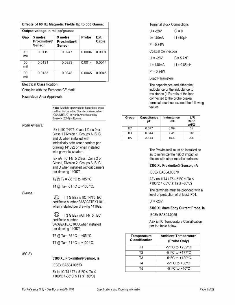
Effects of 60 Hz Magnetic Fields Up to 300 Gauss:
Output voltage in mil pp/gauss:
Gap 5 metre Proximitor® Sensor
9 metre Proximitor Sensor
Probe Ext. Cable
10 mil
0.0119 0.0247 0.0004 0.0004
50 mil
0.0131 0.0323 0.0014 0.0014
90 mil
0.0133 0.0348 0.0045 0.0045
Electrical Classification: Complies with the European CE mark.
Hazardous Area Approvals Note: Multiple approvals for hazardous areas certified by Canadian Standards Association (CSA/NRTL/C) in North America and by Baseefa (2001) in Europe.
North America: Ex ia IIC T4/T5; Class I Zone 0 or Class 1 Division 1; Groups A, B, C, and D, when installed with intrinsically safe zener barriers per drawing 141092 or when installed with galvanic isolators.
Ex nA IIC T4/T5 Class I Zone 2 or Class I, Division 2, Groups A, B, C, and D when installed without barriers per drawing 140979.
T5 @ Ta = -35 °C to +85 °C.
T4 @ Ta= -51 °C to +100 °C.
Europe: II 1 G EEx ia IIC T4/T5. EC certificate number BAS99ATEX1101, when installed per drawing 141092.
II 3 G EEx nAII T4/T5. EC certificate number BAS99ATEX3100U,when installed per drawing 140979
T5 @ Ta= -35 °C to +85 °C
T4 @ Ta= -51 °C to +100 °C.
IEC Ex
3300 XL Proximitor® Sensor, ia
IECEx BAS04.0055X
Ex ia IIC T4 / T5 (-51ºC ≤ Ta ≤ +100ºC / -35ºC ≤ Ta ≤ +85ºC)
Terminal Block Connections
Ui= -28V Ci = 0
Ii= 140mA Li =10µH
Pi= 0.84W
Coaxial Connection
Ui = -28V Ci= 5.7nF
Ii = 140mA Li = 0.85mH
Pi = 0.84W
Load Parameters
The capacitance and either the inductance or the inductance to resistance (L/R) ratio of the load connected to the probe coaxial terminal, must not exceed the following values:
The Proximitor® must be installed so as to minimize the risk of impact or friction with other metallic surfaces.
3300 XL Proximitor® Sensor, nA IECEx BAS04.0057X
AEx nA II T4 / T5 (-51ºC ≤ Ta ≤ +100ºC / -35ºC ≤ Ta ≤ +85ºC)
The terminals must be provided with a level of protection of at least IP54.
Ui = -28V
3300 XL 8mm Eddy Current Probe, ia IECEx BAS04.0056
AEx ia IIC Temperature Classification per the table below.
Group Capacitance µF
Inductance mH
L/R Ratio µH/Ω
IIC 0.077 0.99 35 IIB 0.644 7.41 142 IIA 2.144 15.6 295
Temperature Classification
Ambient Temperature (Probe Only)
T1 -51ºC to +232ºC T2 -51ºC to +177ºC T3 -51ºC to +120ºC T4 -51ºC to +80ºC T5 -51ºC to +40ºC
For Reference Only – See Document #141194 Specifications and Ordering Information Page 6 of 29
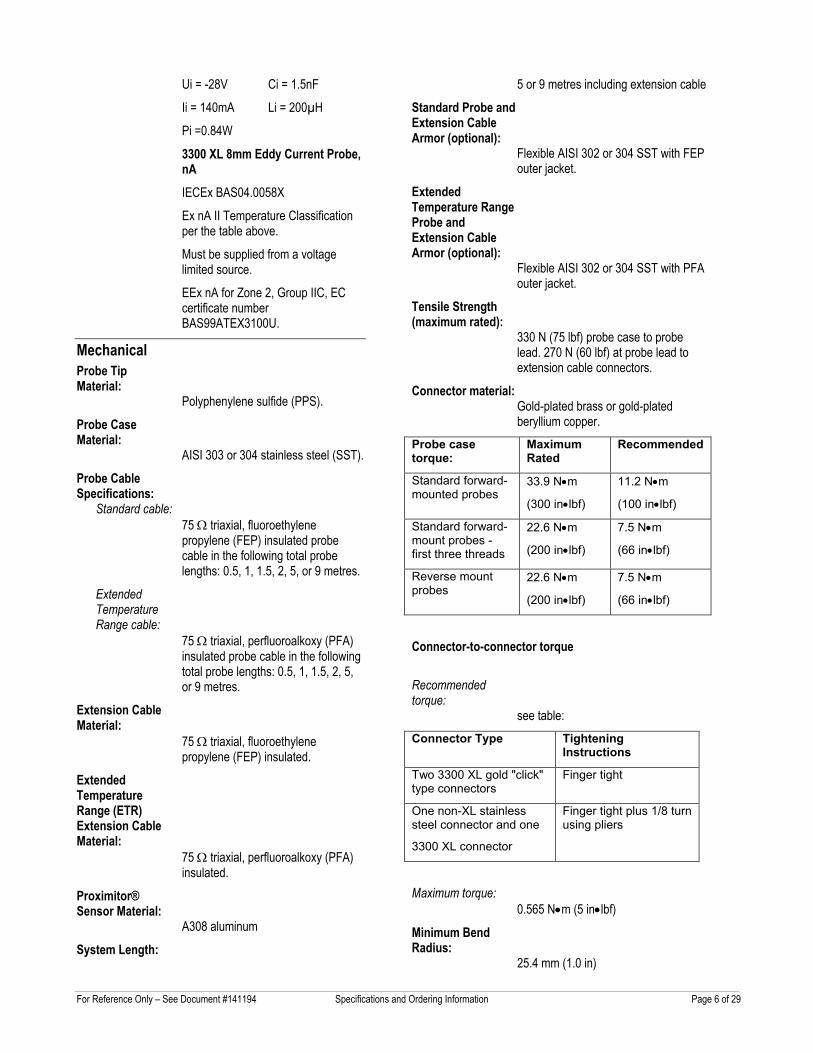
Ui = -28V Ci = 1.5nF
Ii = 140mA Li = 200µH
Pi =0.84W
3300 XL 8mm Eddy Current Probe, nA IECEx BAS04.0058X
Ex nA II Temperature Classification per the table above.
Must be supplied from a voltage limited source.
EEx nA for Zone 2, Group IIC, EC certificate number BAS99ATEX3100U.
Mechanical Probe Tip Material:
Polyphenylene sulfide (PPS).
Probe Case Material:
AISI 303 or 304 stainless steel (SST).
Probe Cable Specifications:
Standard cable: 75 Ω triaxial, fluoroethylene propylene (FEP) insulated probe cable in the following total probe lengths: 0.5, 1, 1.5, 2, 5, or 9 metres.
Extended Temperature Range cable:
75 Ω triaxial, perfluoroalkoxy (PFA) insulated probe cable in the following total probe lengths: 0.5, 1, 1.5, 2, 5, or 9 metres.
Extension Cable Material:
75 Ω triaxial, fluoroethylene propylene (FEP) insulated.
Extended Temperature Range (ETR) Extension Cable Material:
75 Ω triaxial, perfluoroalkoxy (PFA) insulated.
Proximitor® Sensor Material:
A308 aluminum
System Length:
5 or 9 metres including extension cable
Standard Probe and Extension Cable Armor (optional):
Flexible AISI 302 or 304 SST with FEP outer jacket.
Extended Temperature Range Probe and Extension Cable Armor (optional):
Flexible AISI 302 or 304 SST with PFA outer jacket.
Tensile Strength (maximum rated):
330 N (75 lbf) probe case to probe lead. 270 N (60 lbf) at probe lead to extension cable connectors.
Connector material: Gold-plated brass or gold-plated beryllium copper.
Probe case torque:
Maximum Rated
Recommended
Standard forward-mounted probes
33.9 N•m
(300 in•lbf)
11.2 N•m
(100 in•lbf)
Standard forward-mount probes - first three threads
22.6 N•m
(200 in•lbf)
7.5 N•m
(66 in•lbf)
Reverse mount probes
22.6 N•m
(200 in•lbf)
7.5 N•m
(66 in•lbf)
Connector-to-connector torque
Recommended torque:
see table: Connector Type Tightening
Instructions
Two 3300 XL gold "click" type connectors
Finger tight
One non-XL stainless steel connector and one
3300 XL connector
Finger tight plus 1/8 turn using pliers
Maximum torque: 0.565 N•m (5 in•lbf)
Minimum Bend Radius:
25.4 mm (1.0 in)
For Reference Only – See Document #141194 Specifications and Ordering Information Page 7 of 29
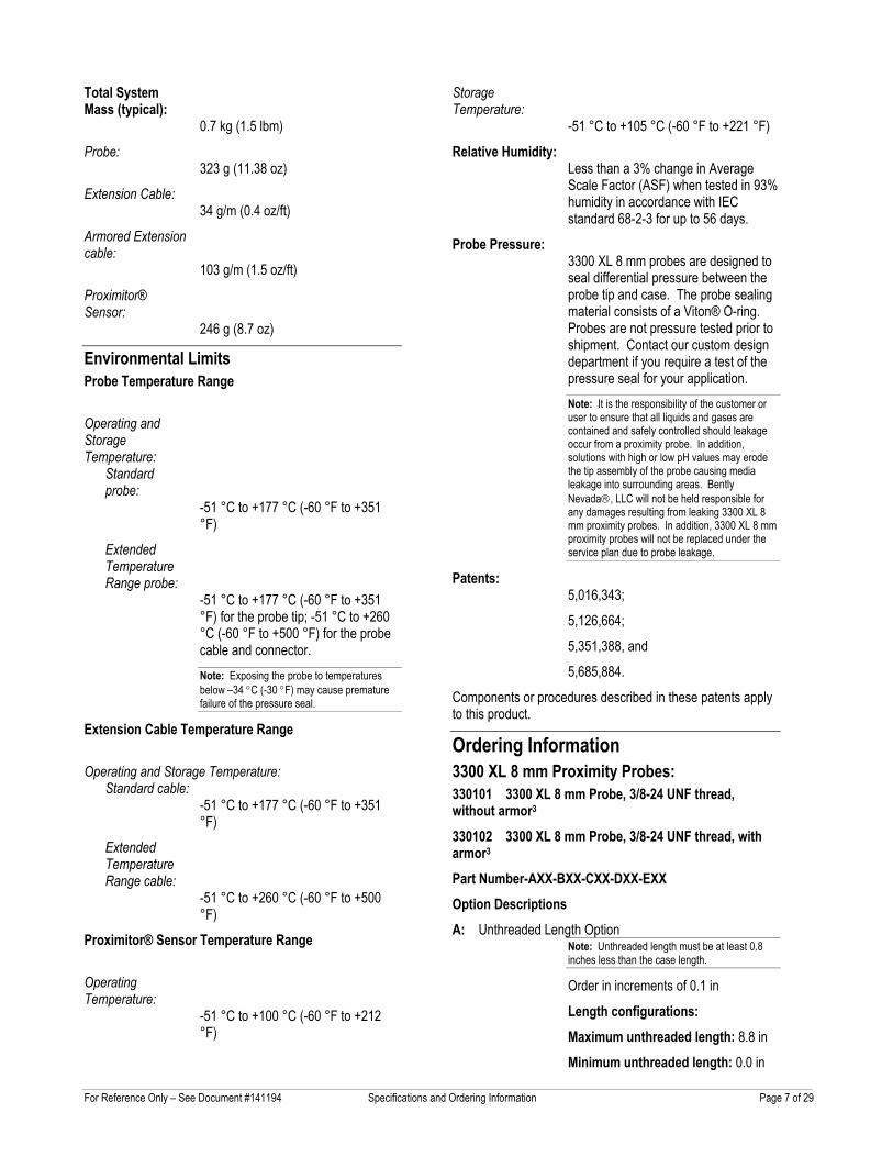
Total System Mass (typical):
0.7 kg (1.5 lbm)
Probe: 323 g (11.38 oz)
Extension Cable: 34 g/m (0.4 oz/ft)
Armored Extension cable:
103 g/m (1.5 oz/ft)
Proximitor® Sensor:
246 g (8.7 oz)
Environmental Limits Probe Temperature Range
Operating and Storage Temperature:
Standard probe:
-51 °C to +177 °C (-60 °F to +351 °F)
Extended Temperature Range probe:
-51 °C to +177 °C (-60 °F to +351 °F) for the probe tip; -51 °C to +260 °C (-60 °F to +500 °F) for the probe cable and connector. Note: Exposing the probe to temperatures below –34 °C (-30 °F) may cause premature failure of the pressure seal.
Extension Cable Temperature Range
Operating and Storage Temperature: Standard cable:
-51 °C to +177 °C (-60 °F to +351 °F)
Extended Temperature Range cable:
-51 °C to +260 °C (-60 °F to +500 °F)
Proximitor® Sensor Temperature Range
Operating Temperature:
-51 °C to +100 °C (-60 °F to +212 °F)
Storage Temperature:
-51 °C to +105 °C (-60 °F to +221 °F)
Relative Humidity: Less than a 3% change in Average Scale Factor (ASF) when tested in 93% humidity in accordance with IEC standard 68-2-3 for up to 56 days.
Probe Pressure: 3300 XL 8 mm probes are designed to seal differential pressure between the probe tip and case. The probe sealing material consists of a Viton® O-ring. Probes are not pressure tested prior to shipment. Contact our custom design department if you require a test of the pressure seal for your application. Note: It is the responsibility of the customer or user to ensure that all liquids and gases are contained and safely controlled should leakage occur from a proximity probe. In addition, solutions with high or low pH values may erode the tip assembly of the probe causing media leakage into surrounding areas. Bently Nevada, LLC will not be held responsible for any damages resulting from leaking 3300 XL 8 mm proximity probes. In addition, 3300 XL 8 mm proximity probes will not be replaced under the service plan due to probe leakage.
Patents: 5,016,343;
5,126,664;
5,351,388, and
5,685,884.
Components or procedures described in these patents apply to this product.
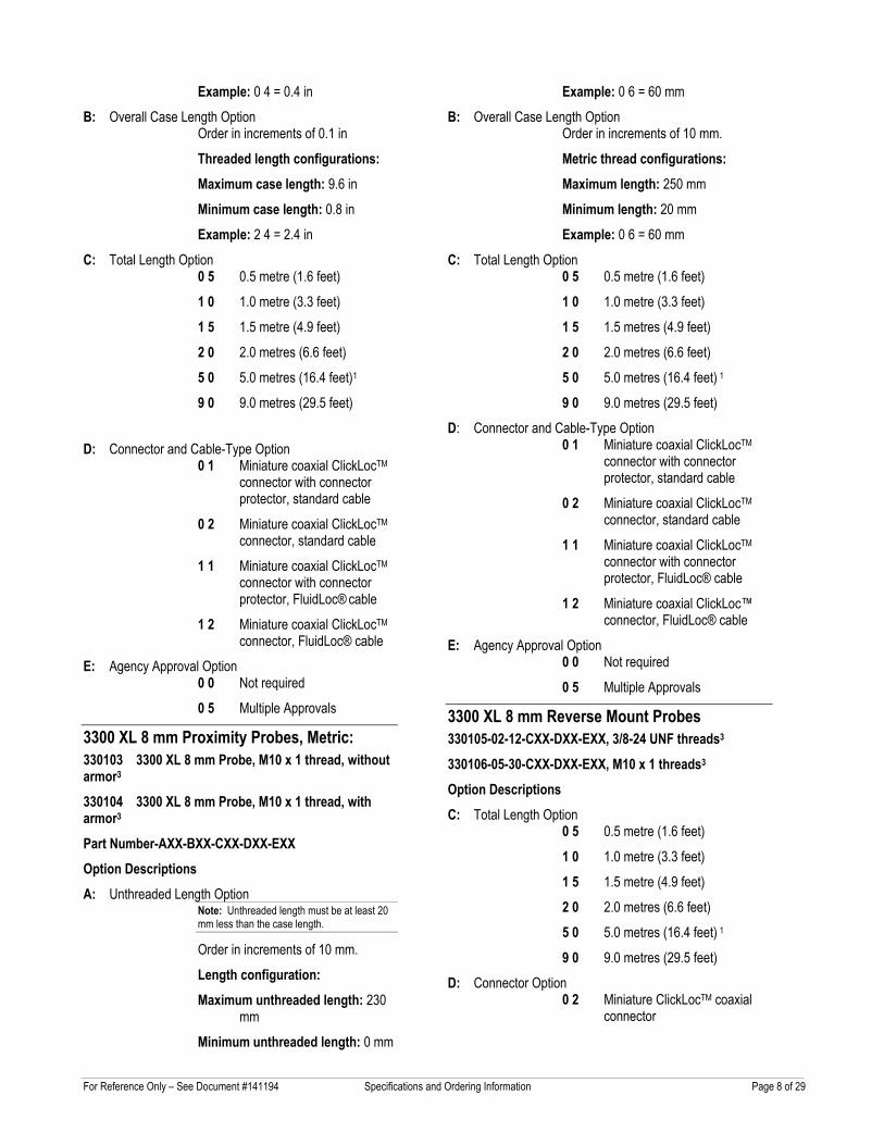
Ordering Information 3300 XL 8 mm Proximity Probes: 330101 3300 XL 8 mm Probe, 3/8-24 UNF thread, without armor3 330102 3300 XL 8 mm Probe, 3/8-24 UNF thread, with armor3 Part Number-AXX-BXX-CXX-DXX-EXX Option Descriptions A: Unthreaded Length Option
Note: Unthreaded length must be at least 0.8 inches less than the case length.
Order in increments of 0.1 in
Length configurations: Maximum unthreaded length: 8.8 in
Minimum unthreaded length: 0.0 in
For Reference Only – See Document #141194 Specifications and Ordering Information Page 8 of 29
Example: 0 4 = 0.4 in
B: Overall Case Length Option Order in increments of 0.1 in
Threaded length configurations: Maximum case length: 9.6 in
Minimum case length: 0.8 in
Example: 2 4 = 2.4 in
C: Total Length Option 0 5 0.5 metre (1.6 feet)
1 0 1.0 metre (3.3 feet)
1 5 1.5 metre (4.9 feet)
2 0 2.0 metres (6.6 feet)
5 0 5.0 metres (16.4 feet)1
9 0 9.0 metres (29.5 feet)
D: Connector and Cable-Type Option
0 1 Miniature coaxial ClickLocTM connector with connector protector, standard cable
0 2 Miniature coaxial ClickLocTM connector, standard cable
1 1 Miniature coaxial ClickLocTM connector with connector protector, FluidLoc® cable
1 2 Miniature coaxial ClickLocTM connector, FluidLoc® cable
E: Agency Approval Option 0 0 Not required
0 5 Multiple Approvals
3300 XL 8 mm Proximity Probes, Metric: 330103 3300 XL 8 mm Probe, M10 x 1 thread, without armor3 330104 3300 XL 8 mm Probe, M10 x 1 thread, with armor3 Part Number-AXX-BXX-CXX-DXX-EXX Option Descriptions A: Unthreaded Length Option
Note: Unthreaded length must be at least 20 mm less than the case length.
Order in increments of 10 mm.
Length configuration: Maximum unthreaded length: 230
mm
Minimum unthreaded length: 0 mm
Example: 0 6 = 60 mm
B: Overall Case Length Option Order in increments of 10 mm.
Metric thread configurations: Maximum length: 250 mm
Minimum length: 20 mm
Example: 0 6 = 60 mm
C: Total Length Option 0 5 0.5 metre (1.6 feet)
1 0 1.0 metre (3.3 feet)
1 5 1.5 metres (4.9 feet)
2 0 2.0 metres (6.6 feet)
5 0 5.0 metres (16.4 feet) 1
9 0 9.0 metres (29.5 feet)
D: Connector and Cable-Type Option 0 1 Miniature coaxial ClickLocTM
connector with connector protector, standard cable
0 2 Miniature coaxial ClickLocTM connector, standard cable
1 1 Miniature coaxial ClickLocTM connector with connector protector, FluidLoc® cable
1 2 Miniature coaxial ClickLoc™ connector, FluidLoc® cable
E: Agency Approval Option 0 0 Not required
0 5 Multiple Approvals
3300 XL 8 mm Reverse Mount Probes 330105-02-12-CXX-DXX-EXX, 3/8-24 UNF threads3 330106-05-30-CXX-DXX-EXX, M10 x 1 threads3 Option Descriptions C: Total Length Option
0 5 0.5 metre (1.6 feet)
1 0 1.0 metre (3.3 feet)
1 5 1.5 metre (4.9 feet)
2 0 2.0 metres (6.6 feet)
5 0 5.0 metres (16.4 feet) 1
9 0 9.0 metres (29.5 feet)
D: Connector Option 0 2 Miniature ClickLocTM coaxial
connector
For Reference Only – See Document #141194 Specifications and Ordering Information Page 9 of 29
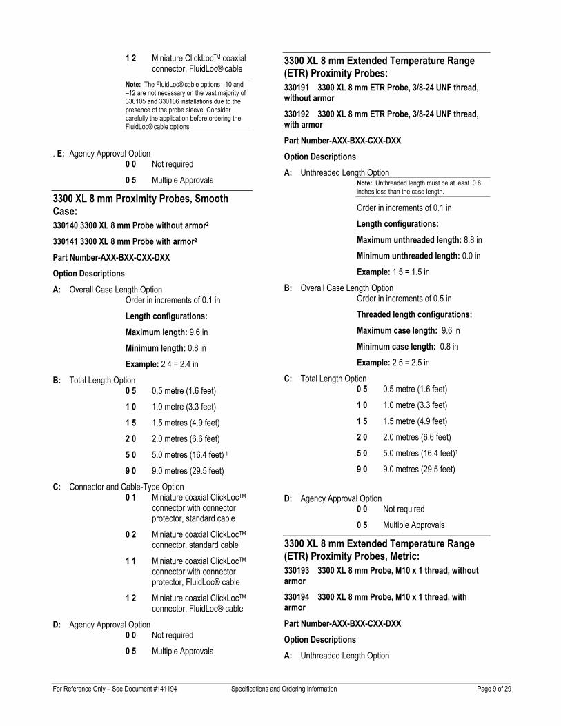
1 2 Miniature ClickLocTM coaxial connector, FluidLoc® cable
Note: The FluidLoc® cable options –10 and –12 are not necessary on the vast majority of 330105 and 330106 installations due to the presence of the probe sleeve. Consider carefully the application before ordering the FluidLoc® cable options
. E: Agency Approval Option
0 0 Not required
0 5 Multiple Approvals
3300 XL 8 mm Proximity Probes, Smooth Case: 330140 3300 XL 8 mm Probe without armor2 330141 3300 XL 8 mm Probe with armor2 Part Number-AXX-BXX-CXX-DXX Option Descriptions A: Overall Case Length Option
Order in increments of 0.1 in
Length configurations: Maximum length: 9.6 in
Minimum length: 0.8 in
Example: 2 4 = 2.4 in
B: Total Length Option 0 5 0.5 metre (1.6 feet)
1 0 1.0 metre (3.3 feet)
1 5 1.5 metres (4.9 feet)
2 0 2.0 metres (6.6 feet)
5 0 5.0 metres (16.4 feet) 1
9 0 9.0 metres (29.5 feet)
C: Connector and Cable-Type Option 0 1 Miniature coaxial ClickLocTM
connector with connector protector, standard cable
0 2 Miniature coaxial ClickLocTM connector, standard cable
1 1 Miniature coaxial ClickLocTM connector with connector protector, FluidLoc® cable
1 2 Miniature coaxial ClickLocTM connector, FluidLoc® cable
D: Agency Approval Option 0 0 Not required
0 5 Multiple Approvals
3300 XL 8 mm Extended Temperature Range (ETR) Proximity Probes: 330191 3300 XL 8 mm ETR Probe, 3/8-24 UNF thread, without armor 330192 3300 XL 8 mm ETR Probe, 3/8-24 UNF thread, with armor Part Number-AXX-BXX-CXX-DXX Option Descriptions A: Unthreaded Length Option
Note: Unthreaded length must be at least 0.8 inches less than the case length.
Order in increments of 0.1 in
Length configurations: Maximum unthreaded length: 8.8 in
Minimum unthreaded length: 0.0 in
Example: 1 5 = 1.5 in
B: Overall Case Length Option Order in increments of 0.5 in
Threaded length configurations: Maximum case length: 9.6 in
Minimum case length: 0.8 in
Example: 2 5 = 2.5 in
C: Total Length Option 0 5 0.5 metre (1.6 feet)
1 0 1.0 metre (3.3 feet)
1 5 1.5 metre (4.9 feet)
2 0 2.0 metres (6.6 feet)
5 0 5.0 metres (16.4 feet)1
9 0 9.0 metres (29.5 feet)
D: Agency Approval Option
0 0 Not required
0 5 Multiple Approvals
3300 XL 8 mm Extended Temperature Range (ETR) Proximity Probes, Metric: 330193 3300 XL 8 mm Probe, M10 x 1 thread, without armor 330194 3300 XL 8 mm Probe, M10 x 1 thread, with armor Part Number-AXX-BXX-CXX-DXX Option Descriptions A: Unthreaded Length Option
For Reference Only – See Document #141194 Specifications and Ordering Information Page 10 of 29
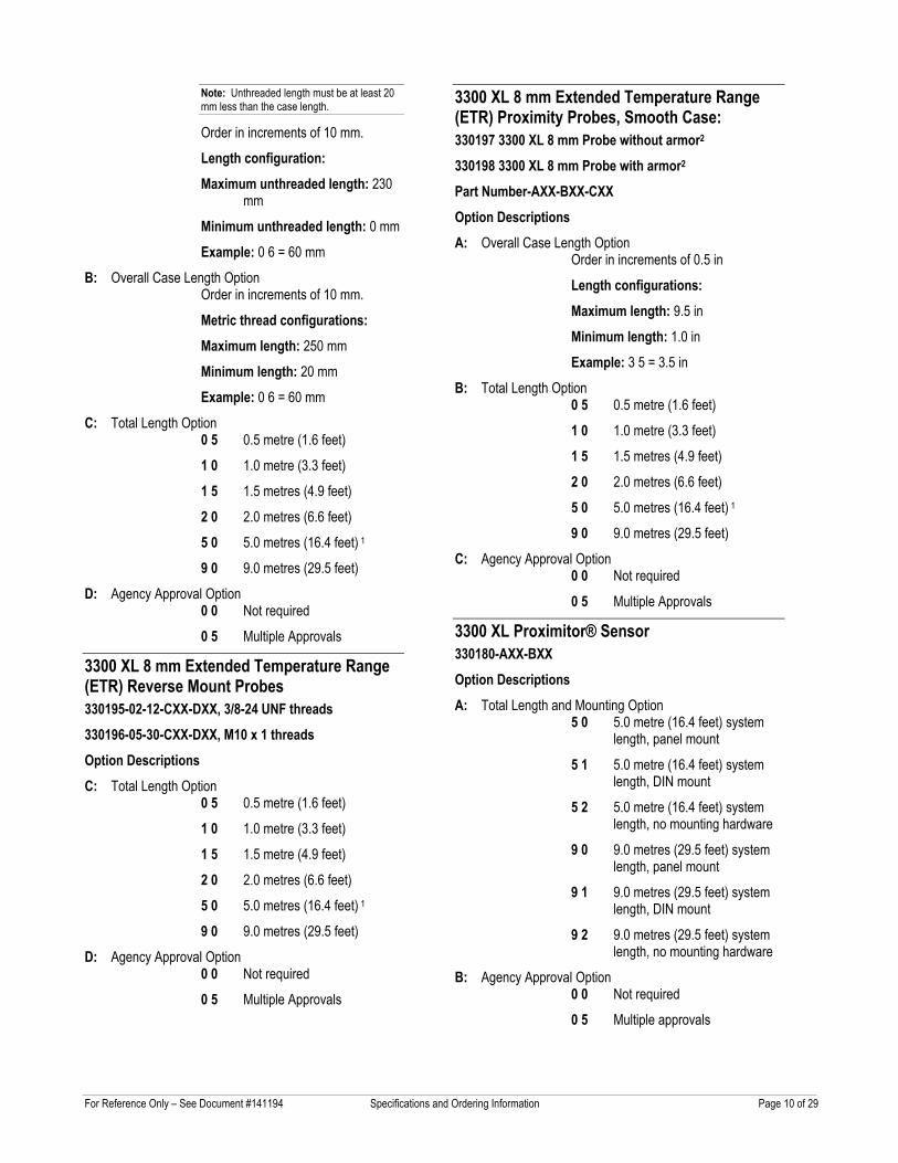
Note: Unthreaded length must be at least 20 mm less than the case length.
Order in increments of 10 mm.
Length configuration: Maximum unthreaded length: 230
mm
Minimum unthreaded length: 0 mm
Example: 0 6 = 60 mm
B: Overall Case Length Option Order in increments of 10 mm.
Metric thread configurations: Maximum length: 250 mm
Minimum length: 20 mm
Example: 0 6 = 60 mm
C: Total Length Option 0 5 0.5 metre (1.6 feet)
1 0 1.0 metre (3.3 feet)
1 5 1.5 metres (4.9 feet)
2 0 2.0 metres (6.6 feet)
5 0 5.0 metres (16.4 feet) 1
9 0 9.0 metres (29.5 feet)
D: Agency Approval Option 0 0 Not required
0 5 Multiple Approvals
3300 XL 8 mm Extended Temperature Range (ETR) Reverse Mount Probes 330195-02-12-CXX-DXX, 3/8-24 UNF threads 330196-05-30-CXX-DXX, M10 x 1 threads Option Descriptions C: Total Length Option
0 5 0.5 metre (1.6 feet)
1 0 1.0 metre (3.3 feet)
1 5 1.5 metre (4.9 feet)
2 0 2.0 metres (6.6 feet)
5 0 5.0 metres (16.4 feet) 1
9 0 9.0 metres (29.5 feet)
D: Agency Approval Option 0 0 Not required
0 5 Multiple Approvals
3300 XL 8 mm Extended Temperature Range (ETR) Proximity Probes, Smooth Case: 330197 3300 XL 8 mm Probe without armor2 330198 3300 XL 8 mm Probe with armor2 Part Number-AXX-BXX-CXX Option Descriptions A: Overall Case Length Option
Order in increments of 0.5 in
Length configurations: Maximum length: 9.5 in
Minimum length: 1.0 in
Example: 3 5 = 3.5 in
B: Total Length Option 0 5 0.5 metre (1.6 feet)
1 0 1.0 metre (3.3 feet)
1 5 1.5 metres (4.9 feet)
2 0 2.0 metres (6.6 feet)
5 0 5.0 metres (16.4 feet) 1
9 0 9.0 metres (29.5 feet)
C: Agency Approval Option 0 0 Not required
0 5 Multiple Approvals
3300 XL Proximitor® Sensor 330180-AXX-BXX Option Descriptions A: Total Length and Mounting Option
5 0 5.0 metre (16.4 feet) system length, panel mount
5 1 5.0 metre (16.4 feet) system length, DIN mount
5 2 5.0 metre (16.4 feet) system length, no mounting hardware
9 0 9.0 metres (29.5 feet) system length, panel mount
9 1 9.0 metres (29.5 feet) system length, DIN mount
9 2 9.0 metres (29.5 feet) system length, no mounting hardware
B: Agency Approval Option 0 0 Not required
0 5 Multiple approvals
For Reference Only – See Document #141194 Specifications and Ordering Information Page 11 of 29
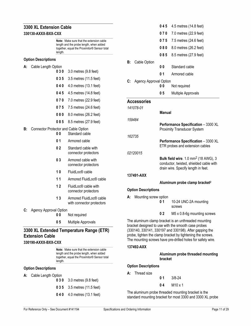
3300 XL Extension Cable 330130-AXXX-BXX-CXX
Note: Make sure that the extension cable length and the probe length, when added together, equal the Proximitor® Sensor total length.
Option Descriptions A: Cable Length Option
0 3 0 3.0 metres (9.8 feet)
0 3 5 3.5 metres (11.5 feet)
0 4 0 4.0 metres (13.1 feet)
0 4 5 4.5 metres (14.8 feet)
0 7 0 7.0 metres (22.9 feet)
0 7 5 7.5 metres (24.6 feet)
0 8 0 8.0 metres (26.2 feet)
0 8 5 8.5 metres (27.9 feet)
B: Connector Protector and Cable Option 0 0 Standard cable
0 1 Armored cable
0 2 Standard cable with connector protectors
0 3 Armored cable with connector protectors
1 0 FluidLoc® cable
1 1 Armored FluidLoc® cable
1 2 FluidLoc® cable with connector protectors
1 3 Armored FluidLoc® cable with connector protectors
C: Agency Approval Option 0 0 Not required
0 5 Multiple Approvals
3300 XL Extended Temperature Range (ETR) Extension Cable 330190-AXXX-BXX-CXX
Note: Make sure that the extension cable length and the probe length, when added together, equal the Proximitor® Sensor total length.
Option Descriptions A: Cable Length Option
0 3 0 3.0 metres (9.8 feet)
0 3 5 3.5 metres (11.5 feet)
0 4 0 4.0 metres (13.1 feet)
0 4 5 4.5 metres (14.8 feet)
0 7 0 7.0 metres (22.9 feet)
0 7 5 7.5 metres (24.6 feet)
0 8 0 8.0 metres (26.2 feet)
0 8 5 8.5 metres (27.9 feet)
B: Cable Option 0 0 Standard cable
0 1 Armored cable
C: Agency Approval Option 0 0 Not required
0 5 Multiple Approvals
Accessories 141078-01
Manual 159484
Performance Specification – 3300 XL Proximity Transducer System
162735 Performance Specification – 3300 XL ETR probes and extension cables
02120015 Bulk field wire. 1.0 mm2 (18 AWG), 3 conductor, twisted, shielded cable with drain wire. Specify length in feet.
137491-AXX Aluminum probe clamp bracket2
Option Descriptions A: Mounting screw option
0 1 10-24 UNC-2A mounting screws
0 2 M5 x 0.8-6g mounting screws
The aluminum clamp bracket is an unthreaded mounting bracket designed to use with the smooth case probes (330140, 330141, 330197 and 330198). After gapping the probe, tighten the clamp bracket by tightening the screws. The mounting screws have pre-drilled holes for safety wire.
137492-AXX Aluminum probe threaded mounting bracket
Option Descriptions A: Thread size
0 1 3/8-24
0 4 M10 x 1
The aluminum probe threaded mounting bracket is the standard mounting bracket for most 3300 and 3300 XL probe
For Reference Only – See Document #141194 Specifications and Ordering Information Page 12 of 29
installations. The -01 option is supplied with two 10-24 UNC-2A mounting screws. The -04 option is supplied with two M5 x 0.8-6g mounting screws. The mounting screws have pre-drilled holes for safety wire.
27474-AXX Phenolic threaded probe mounting bracket
Option Descriptions A: Thread size
0 1 3/8-24
0 4 M10 x 1
The phenolic threaded mounting bracket is recommended if additional electric isolation from the mounting location is required (as in some generator and electrical motor bearing locations). The -01 option is supplied with two 10-24 UNC-2A mounting screws. The -04 option is supplied with two M5 x 0.8-6g mounting screws. The mounting screws have pre-drilled holes for safety wire.
138492-01 Replacement panel-mount mounting pad
138493-01 Replacement DIN-mount mounting pad
148722-01 3300 XL Test Plug. The 3300 XL Test Plug contains three small test pins attached to three color-coded wires 1 metre in length, each terminated in a banana plug. The three-pin adapter plugs into the test pin holes on 3300 XL-style Proximitor® Sensors. It is used to check the performance of the Proximitor® Sensor from the test pin holes in the terminal strip without requiring the removal of the field wiring.
04310310 3300 XL Proximitor® Sensor Panel-mount Screws. Package includes four 6-32 UNC thread forming mounting screws. (Supplied standard with Proximitor® Housings [3300 XL panel-mount option]).
03200006 Silicone self-fusing tape. A 9.1 metre (10 yard) roll of silicone tape to protect connectors. It is easy to install and provides excellent electrical isolation and protection from the environment. It is not recommended
for use inside the casing of the machine.
40113-02 Connector Protector Kit. Connector Protector Kit for 3300 XL 8 mm probes and extension cables, including connector protectors and installation tools.
136536-01 Connector Protector Adapter. Allows connector protector installation tools manufactured prior to 1998 to be used with 75 Ω ClickLoc™ connectors.
40180-02 Connector Protectors. Package contains 10 pairs of connector protectors for 3300 XL 8 mm probes and 3300 XL 5 and 8 mm extension cables.
03839410 75 ohm Triaxial Male Connector Protector. Male connector protectors are installed onto the extension cable and attach to the female connector protector on the probe, providing environmental protection of connectors.
03839420 75 ohm Triaxial Female Connector Protector. Female connector protectors are installed onto the probe lead and attach to the male connector protector on the extension cable, providing environmental protection of connectors. Also placed on the extension cable to slide over the connection to the Proximitor® Sensor and protect it from the environment.
04301007 3/8-24 Probe Lock Nut with safety wire holes. Single probe lock nut with two holes drilled through the nut in order to secure the lock nut in place with safety wire.
04301008 M10 x 1 Probe Lock Nut with safety wire holes. Single probe lock nut with two holes drilled through the nut in order to secure the lock nut in place with safety wire.
330153-01 3300 XL Connector Kit. Used on 3300 XL 8 mm probes and extension cables. Contains one pair of male and female ClickLocTM connectors, two
For Reference Only – See Document #141194 Specifications and Ordering Information Page 13 of 29
color-coded sleeves, two pieces of slit FEP tubing, and one strip of silicone tape.
163356 Connector Crimp Tool Kit. Includes one set of multiconnector inserts and connector installation instructions. Compatible only with 330153 connector kits or with probes shipped in 2003 or later with ClickLoc™ connectors uninstalled. Supplied with carrying case.
Notes: 1. Five metre probes are designed for use with the
five metre Proximitor® Sensor only.
2. Mounting clamps must be ordered separately for 330140, 330141, 330197, and 330198.
3. For a shorter delivery time, order commonly stocked probes. Currently, stocked probes consist of the following part numbers:
330101-00-08-05-02-00, 330101-00-08-05-02-05, 330101-00-08-10-02-00, 330101-00-08-10-
02-05, 330101-00-12-10-02-00, 330101-00-12-10-02-05, 330101-00-16-10-02-00, 330101-00-16-10-02-05, 330101-00-20-05-02-00, 330101-00-20-10-02-00, 330101-00-20-10-02-05, 330101-00-30-10-02-00, 330101-00-30-10-02-05, 330101-00-40-05-02-00, 330101-00-40-10-02-00, 330101-00-40-10-02-05, 330101-00-60-10-02-00, 330101-00-60-10-02-05, 330102-00-20-10-02-00, 330103-00-02-10-02-05, 330103-00-03-10-02-05, 330103-00-04-10-02-00, 330103-00-04-50-02-00, 330103-00-05-10-02-00, 330103-00-06-10-02-00, 330104-00-06-10-02-00, 330104-01-05-50-02-00, 330105-02-12-05-02-00, 330105-02-12-05-02-05, 330105-02-12-10-02-00, 330105-02-12-10-02-05, 330106-05-30-05-02-00, 330106-05-30-05-02-05, 330106-05-30-10-02-00 and 330106-05-30-10-02-05.
Graphs and Dimensional Drawings
For Reference Only – See Document #141194 Specifications and Ordering Information Page 14 of 29
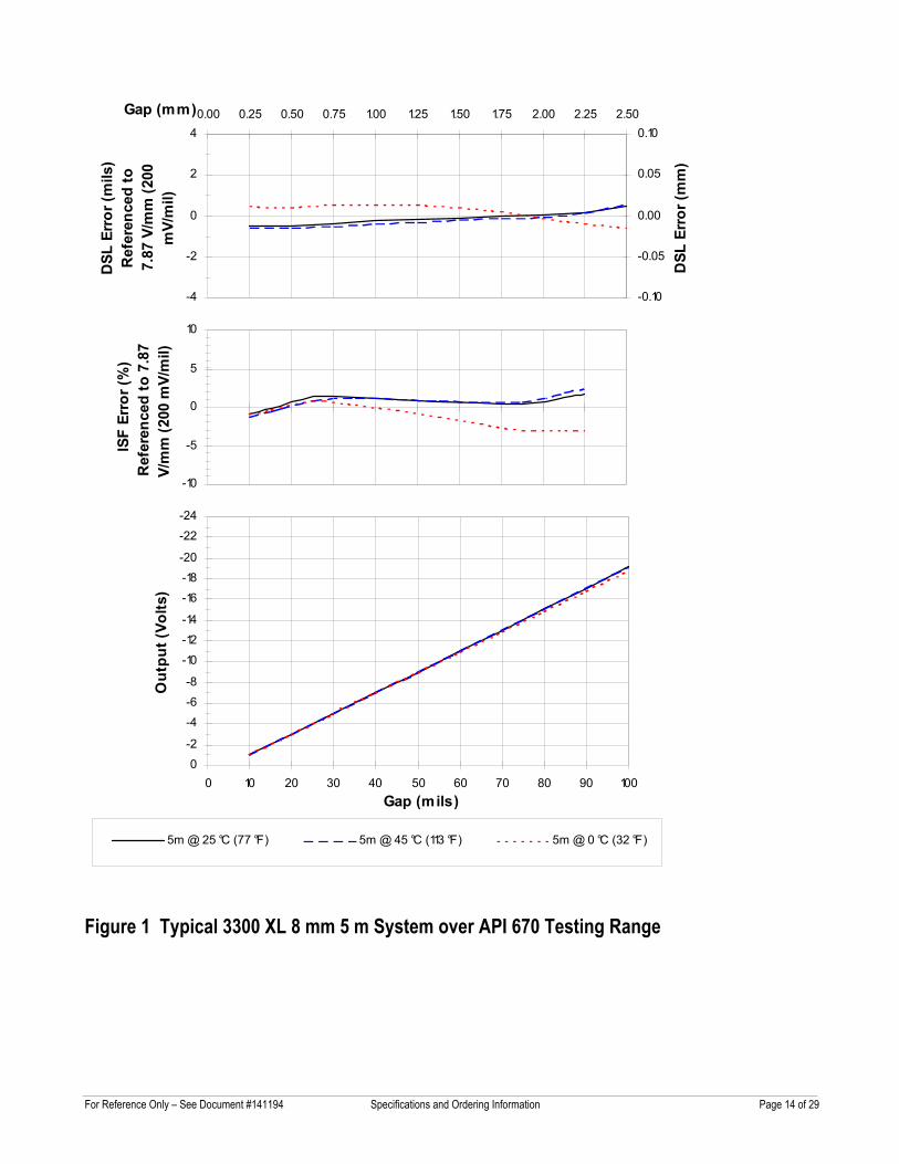
Figure 1 Typical 3300 XL 8 mm 5 m System over API 670 Testing Range
-4
-2
0
2
4
DSL
Err
or (m
ils)
Ref
eren
ced
to
7.87
V/m
m (2
00
mV/
mil)
-0.10
-0.05
0.00
0.05
0.100.00 0.25 0.50 0.75 1.00 1.25 1.50 1.75 2.00 2.25 2.50Gap (mm)
DSL
Err
or (m
m)
-10
-5
0
5
10
ISF
Erro
r (%
)R
efer
ence
d to
7.8
7 V/
mm
(200
mV/
mil)
-24
-22
-20-18
-16
-14
-12
-10
-8
-6
-4
-2
00 10 20 30 40 50 60 70 80 90 100
Gap (mils)
Out
put (
Volts
)
5m @ 25 °C (77 °F) 5m @ 45 °C (113 °F) 5m @ 0 °C (32 °F)
For Reference Only – See Document #141194 Specifications and Ordering Information Page 15 of 29
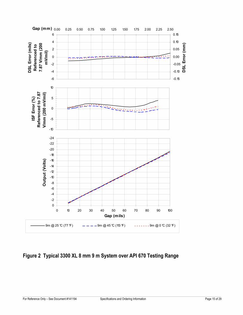
Figure 2 Typical 3300 XL 8 mm 9 m System over API 670 Testing Range
-6
-4
-2
0
2
4
6D
SL E
rror
(mils
)R
efer
ence
d to
7.
87 V
/mm
(200
m
V/m
il)
-0.15
-0.10
-0.05
0.00
0.05
0.10
0.150.00 0.25 0.50 0.75 1.00 1.25 1.50 1.75 2.00 2.25 2.50Gap (mm)
DSL
Err
or (m
m)
-10
-5
0
5
10
ISF
Erro
r (%
)R
efer
ence
d to
7.8
7 V/
mm
(200
mV/
mil)
-24
-22
-20-18
-16
-14
-12
-10
-8
-6
-4
-2
00 10 20 30 40 50 60 70 80 90 100
Gap (mils)
Out
put (
Volts
)
9m @ 25 °C (77 °F) 9m @ 45 °C (113 °F) 9m @ 0 °C (32 °F)
For Reference Only – See Document #141194 Specifications and Ordering Information Page 16 of 29
Figure 3 Typical 3300 XL 8 mm Probe over API 670 Operating Range
-6
-4
-2
0
2
4
6D
SL E
rror
(mils
)R
efer
ence
d to
7.
87 V
/mm
(200
m
V/m
il)
-0.15
-0.10
-0.05
0.00
0.05
0.10
0.150.00 0.25 0.50 0.75 1.00 1.25 1.50 1.75 2.00 2.25 2.50Gap (mm)
DSL
Err
or (m
m)
-10
-5
0
5
10
ISF
Erro
r (%
)R
efer
ence
d to
7.8
7 V/
mm
(200
mV/
mil)
-24
-22
-20
-18
-16
-14-12
-10
-8
-6
-4
-2
00 10 20 30 40 50 60 70 80 90 100
Gap (mils)
Out
put (
Volts
)
1m Probe @ 25 °C (77 °F) 1m Probe @ -35 °C (-31 °F)1m Probe @ 120 °C (248 °F)
For Reference Only – See Document #141194 Specifications and Ordering Information Page 17 of 29
Figure 4 Typical 3300 XL 8 mm 5 m Proximitor® Sensor with 4 m of Extension Cable @ Tc (Probe is at 25 °C)
-6
-4
-2
0
2
4
6D
SL E
rror
(mils
)R
efer
ence
d to
7.
87 V
/mm
(200
m
V/m
il)
-0.15
-0.10
-0.05
0.00
0.05
0.10
0.150.00 0.25 0.50 0.75 1.00 1.25 1.50 1.75 2.00 2.25 2.50Gap (mm)
DSL
Err
or (m
m)
-10
-5
0
5
10
ISF
Erro
r (%
)R
efer
ence
d to
7.8
7 V/
mm
(200
mV/
mil)
-24
-22
-20
-18
-16
-14
-12
-10
-8
-6
-4
-2
00 10 20 30 40 50 60 70 80 90 100
Gap (mils)
Out
put (
Volts
)
TC=25 °C (77 °F) Tc=-34 °C (-30 °F) Tc=-51 °C (-60 °F)
For Reference Only – See Document #141194 Specifications and Ordering Information Page 18 of 29
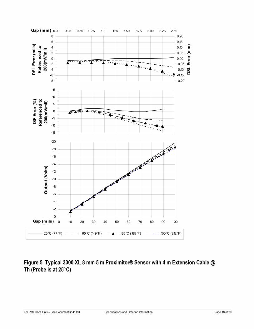
Figure 5 Typical 3300 XL 8 mm 5 m Proximitor® Sensor with 4 m Extension Cable @ Th (Probe is at 25°C)
-8
-6-4
-202
46
8D
SL E
rror
(mils
)R
efer
ence
d to
20
0(m
V/m
il)
-0.20
-0.15-0.10
-0.050.000.05
0.100.15
0.200.00 0.25 0.50 0.75 1.00 1.25 1.50 1.75 2.00 2.25 2.50Gap (mm)
DSL
Err
or (m
m)
-15
-10
-5
0
5
10
15
ISF
Erro
r (%
) R
efer
ence
d to
20
0(m
V/m
il)
-20
-18
-16
-14
-12
-10
-8
-6
-4
-2
00 10 20 30 40 50 60 70 80 90 100Gap (mils)
Out
put (
Volts
)
25 °C (77 °F) 65 °C (149 °F) 85 °C (185 °F) 100 °C (212 °F)
For Reference Only – See Document #141194 Specifications and Ordering Information Page 19 of 29
Figure 6 Typical 3300 XL 8 mm 9 m Proximitor® Sensor with 8 m of Extension Cable @ Tc (Probe is at 25 °C)
-8-6-4-202468
DSL
Err
or (m
ils)
-0.20-0.15-0.10-0.050.000.050.100.150.20
0.00 0.25 0.50 0.75 1.00 1.25 1.50 1.75 2.00 2.25 2.50Gap (mm)
DSL
Err
or (m
m)
-15
-10
-5
0
5
10
15
ISF
Erro
r (%
)
-22
-20
-18
-16
-14
-12
-10
-8
-6
-4
-2
00 10 20 30 40 50 60 70 80 90 100
Gap (mils)
Out
put (
Volts
)
Tc=+25 °C (+77 °F) Tc=-34 °C (-30 °F) Tc=-51 °C (-60 °F)
For Reference Only – See Document #141194 Specifications and Ordering Information Page 20 of 29
-8-6-4-202468
DSL
Err
or (m
ils)
-0.20-0.15-0.10-0.050.000.050.100.150.20
0.00 0.25 0.50 0.75 1.00 1.25 1.50 1.75 2.00 2.25 2.50Gap (mm)
DSL
Err
or (m
m)
-15
-10
-5
0
5
10
15
ISF
Erro
r (%
)
-22
-20
-18
-16
-14
-12
-10
-8
-6
-4
-2
00 10 20 30 40 50 60 70 80 90 100
Gap (mils)
Out
put (
Volts
)
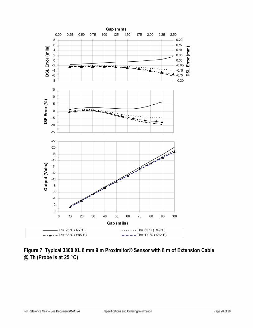
Th=+25 °C (+77 °F) Th=+65 °C (+149 °F)Th=+85 °C (+185 °F) Th=+100 °C (+212 °F)
Figure 7 Typical 3300 XL 8 mm 9 m Proximitor® Sensor with 8 m of Extension Cable @ Th (Probe is at 25 °C)
For Reference Only – See Document #141194 Specifications and Ordering Information Page 21 of 29
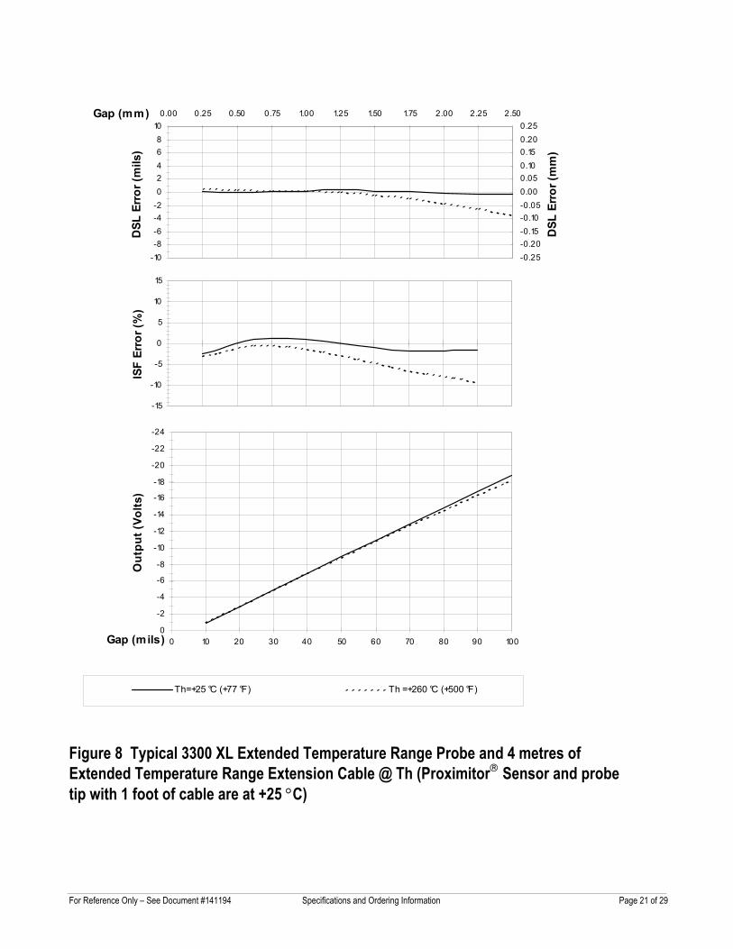
Figure 8 Typical 3300 XL Extended Temperature Range Probe and 4 metres of Extended Temperature Range Extension Cable @ Th (Proximitor Sensor and probe tip with 1 foot of cable are at +25 °C)
-10-8-6-4-202468
10D
SL E
rror
(mils
)
-0.25-0.20-0.15-0.10-0.050.000.050.100.150.200.25
0.00 0.25 0.50 0.75 1.00 1.25 1.50 1.75 2.00 2.25 2.50Gap (mm)
DSL
Err
or (m
m)
-15
-10
-5
0
5
10
15
ISF
Erro
r (%
)
-24
-22
-20
-18
-16
-14
-12
-10
-8
-6
-4
-2
00 10 20 30 40 50 60 70 80 90 100Gap (mils)
Out
put (
Volts
)
Th=+25 °C (+77 °F) Th =+260 °C (+500 °F)
For Reference Only – See Document #141194 Specifications and Ordering Information Page 22 of 29
-10-8-6-4-202468
10
DSL
Err
or (m
ils)
-0.25-0.20-0.15-0.10-0.050.000.050.100.150.200.25
0.00 0.25 0.50 0.75 1.00 1.25 1.50 1.75 2.00 2.25 2.50Gap (mm)
DSL
Err
or (m
m)
-15
-10
-5
0
5
10
15
ISF
Erro
r (%
)
-24
-22
-20
-18
-16
-14
-12
-10
-8
-6
-4
-2
00 10 20 30 40 50 60 70 80 90 100Gap (mils)
Out
put (
Volts
)
Th=+25 °C (+77 °F) Th=+260 °C (+500 °F)
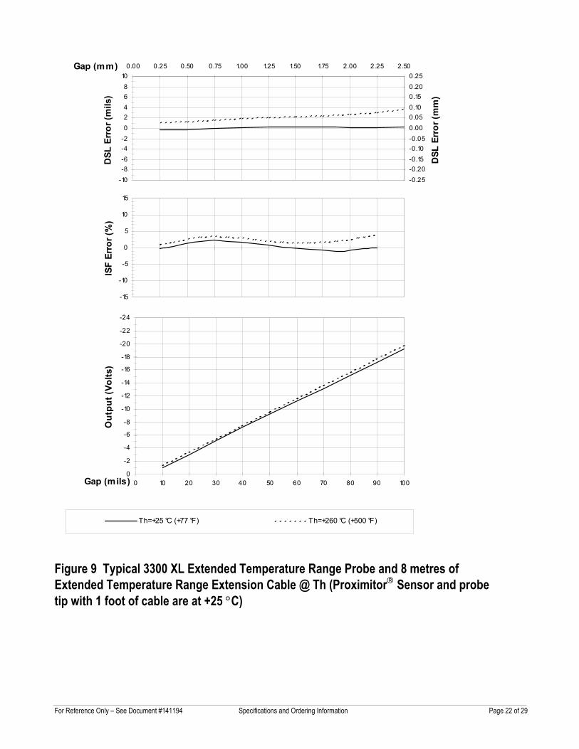
Figure 9 Typical 3300 XL Extended Temperature Range Probe and 8 metres of Extended Temperature Range Extension Cable @ Th (Proximitor Sensor and probe tip with 1 foot of cable are at +25 °C)
For Reference Only – See Document #141194 Specifications and Ordering Information Page 23 of 29
Frequency Response to Different Field Wiring Lengths without Barriers (5 m System)
-5
-4
-3
-2
-1
0
1
100 1,000 10,000 100,000Frequency (Hz)
Mag
nitu
de (d
B)
No field wiring 1000' wiring 2000' wiring5000' wiring 12,000' wiring
Figure 10 Frequency Response, typical 3300 XL 8 mm 5 m System with varying lengths of field wiring attached, no barriers
Phase Response with Different Field Wiring Lengths, No Barriers (5 m System)
-100
-90
-80
-70
-60
-50
-40
-30
-20
-10
0
100 1,000 10,000 100,000Frequency (Hz)
Phas
e A
ngle
(deg
rees
)
No field wiring 1000' wiring 2000' wiring5000' wiring 12,000' wiring
Figure 11 Phase Response, typical 3300 XL 8 mm 5 m System with varying lengths of field wiring attached, no barriers
For Reference Only – See Document #141194 Specifications and Ordering Information Page 24 of 29
Frequency Response to Different Field Wiring Lengths without Barriers (9 m System)
-5
-4
-3
-2
-1
0
1
100 1,000 10,000 100,000Frequency (Hz)
Mag
nitu
de (d
B)
No field wiring 1000' field wiring 2000' field wiring5000' field wiring 12,000' field wiring
Figure 12 Frequency Response, typical 3300 XL 8 mm 9 m System with varying lengths of field wiring attached, no barriers
Figure 13 Phase Response, typical 3300 XL 8 mm 9 m System with varying lengths of field wiring attached, no barriers
Phase Response with Different Field Wiring Lengths, No Barriers (9 m System)
-100.00
-90.00-80.00
-70.00-60.00
-50.00
-40.00-30.00
-20.00-10.00
0.00
100 1,000 10,000 100,000Frequency (Hz)
Phas
e A
ngle
(deg
rees
)
No field wiring 1000' field wiring 2000' field wiring5000' field wiring 12,000' field wiring
For Reference Only – See Document #141194 Specifications and Ordering Information Page 25 of 29
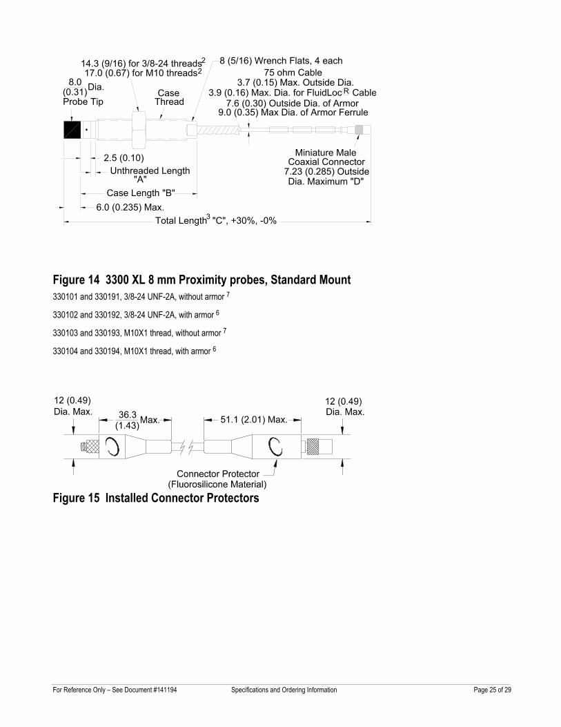
Figure 14 3300 XL 8 mm Proximity probes, Standard Mount 330101 and 330191, 3/8-24 UNF-2A, without armor 7
330102 and 330192, 3/8-24 UNF-2A, with armor 6
330103 and 330193, M10X1 thread, without armor 7
330104 and 330194, M10X1 thread, with armor 6
Figure 15 Installed Connector Protectors
17.0 (0.67) for M10 threads14.3 (9/16) for 3/8-24 threads 8 (5/16) Wrench Flats, 4 each
(0.31)
6.0 (0.235) Max.Case Length "B"
8.0
Probe Tip
Total Length "C", +30%, -0%
ThreadCase
3.7 (0.15) Max. Outside Dia.75 ohm Cable
Coaxial ConnectorMiniature Male
7.23 (0.285) OutsideDia. Maximum "D"
7.6 (0.30) Outside Dia. of Armor
Unthreaded Length "A"
2.5 (0.10)
Dia.
22
3
R
9.0 (0.35) Max Dia. of Armor Ferrule
For Reference Only – See Document #141194 Specifications and Ordering Information Page 26 of 29
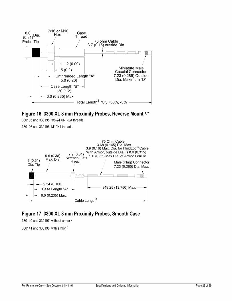
Figure 16 3300 XL 8 mm Proximity Probes, Reverse Mount 4, 7 330105 and 330195, 3/8-24 UNF-2A threads
330106 and 330196, M10X1 threads
With Armor, outside Dia. is 8.0 (0.315)
3.68 (0.145) Dia. Max.
Max. Dia.8 (0.31)Dia. Tip
6.0 (0.235) Max.
2.54 (0.100) Case Length "A"
9.6 (0.38)4 each
7.9 (0.31)Wrench Flats
7.23 (0.285) Dia. Max.
349.25 (13.750) Max.
Cable Length
Male (Plug) Connector
75 Ohm Cable
3.9 (0.16) Max. Dia. for FluidLoc Cable
3
R
9.0 (0.35) Max Dia. of Armor Ferrule
Figure 17 3300 XL 8 mm Proximity Probes, Smooth Case 330140 and 330197, without armor 7
330141 and 330198, with armor 6
For Reference Only – See Document #141194 Specifications and Ordering Information Page 27 of 29
Coaxial ConnectorMiniature Female
Triaxial CableFEP or PFA Insulated
8.4 (0.33) Dia.Stainless Steel Ferrules
Cable Length +20%, -0%
7.2 (0.285)
300 (11.8)Armor Length:(3.30)
83.8
Coaxial ConnectorMiniature Male
Max. Dia.7.2 (0.285)
less than cable length
(3.30)83.8
(3.30)83.883.8
(3.30)
3.7 (0.15) max. O.D.3.9 (0.16) Max. Dia. for FluidLoc cable
7.6 (0.30) Max. O.D. of Armor
75 ohm cable
Max. Dia.Coated Armor
FEP or PFA6
R
9.0 (0.35) Max Dia. of Armor Ferrule
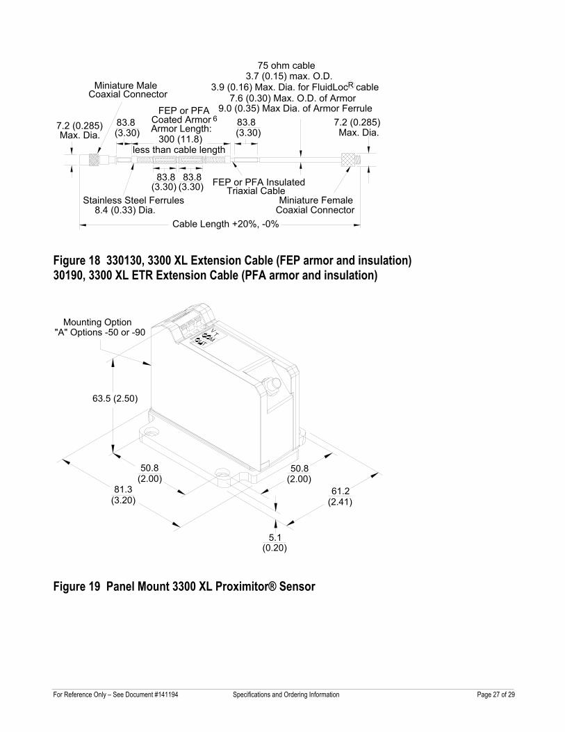
Figure 18 330130, 3300 XL Extension Cable (FEP armor and insulation) 30190, 3300 XL ETR Extension Cable (PFA armor and insulation)
Figure 19 Panel Mount 3300 XL Proximitor® Sensor
Mounting Option"A" Options -50 or -90
63.5 (2.50)
50.8(2.00)
81.3(3.20)
50.8(2.00)
61.2(2.41)
5.1(0.20)
For Reference Only – See Document #141194 Specifications and Ordering Information Page 28 of 29
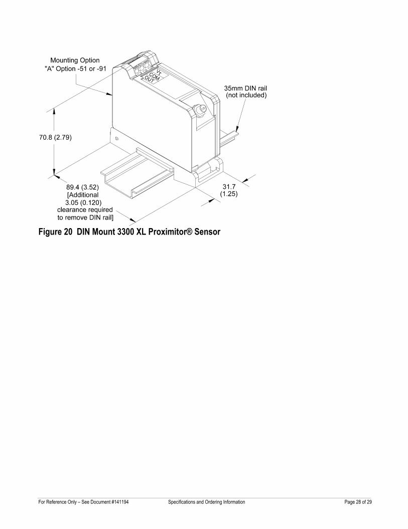
Figure 20 DIN Mount 3300 XL Proximitor® Sensor
For Reference Only – See Document #141194 Specifications and Ordering Information Page 29 of 29
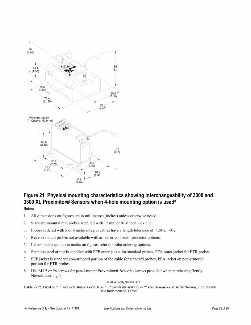
Figure 21 Physical mounting characteristics showing interchangeability of 3300 and 3300 XL Proximitor® Sensors when 4-hole mounting option is used8 Notes: 1. All dimensions on figures are in millimetres (inches) unless otherwise noted.
2. Standard mount 8 mm probes supplied with 17 mm or 9/16 inch lock nut.
3. Probes ordered with 5 or 9 metre integral cables have a length tolerance of +20%, -0%.
4. Reverse mount probes not available with armor or connector protector options.
5. Letters inside quotation marks on figures refer to probe ordering options.
6. Stainless steel armor is supplied with FEP outer jacket for standard probes, PFA outer jacket for ETR probes.
7. FEP jacket is standard non-armored portion of the cable for standard probes, PFA jacket on non-armored portion for ETR probes.
8. Use M3.5 or #6 screws for panel-mount Proximitor® Sensors (screws provided when purchasing Bently Nevada housings).
© 2004 Bently Nevada LLC CableLoc™, ClickLoc™, FluidLoc®, Keyphasor®, NSv™, Proximitor®, and TipLoc™ are trademarks of Bently Nevada, LLC. Viton®
is a trademark of DuPont.
50
25.4
(1.95)
50.8(2.00)
60.2(2.37)
50.8(2.00)
79.4(3.125)
(1.00)
R
86(3.4)
Mounting Option"A" Options -50 or -90
63.5
50.8(2.00)
81.3(3.20)
50.8(2.00)
61.2(2.41)
5.1(0.20)
(2.50)
(3.2)81