Embed Size (px)
Citation preview

13th International Conference on Probabilistic Safety Assessment and Management (PSAM 13)
2~7 October, 2016 • Sheraton Grande Walkerhill • Seoul, Korea • www.psam13.org
1
PROBABILISTIC RISK ASSESSMENT OF INTERIM DRY STORAGE FACILITY SUBJECTED TO AN
AIRCRAFT IMPACT
Belal Almomani1, Sanghoon Lee2, Hyun Gook Kang3
1 Department of Nuclear and Quantum Eng., KAIST, Daejeon, 305-701, Republic of Korea. [email protected]
2 Department of Mechanical and Automotive Eng., Keimyung University, Daegu, Republic of Korea. [email protected] 3 Department of Mechanical, Aerospace and Nuclear Eng., RPI, Troy, NY 12180, U.S.A. [email protected]
This paper provides a risk evaluation framework of aircraft impact on an interim dry storage facility by using a
probabilistic approach. A realistic case study that includes a specific cask model and selected impact conditions is performed
to demonstrate the practical applicability of the proposed framework. An event tree analysis that defines a set of impact
conditions and the storage cask response is constructed. The Monte-Carlo simulation is employed for the probabilistic
approach in consideration of by sources of uncertainty associated with the impact loads onto the internal storage casks. A
finite element analysis is used to simulate the postulated direct engine impact load onto the cask body. A source term analysis
for associated releases of radioactive materials and an off-site consequence analysis are performed. Finally, the risk
contribution calculations are represented by the event tree model. The proposed risk model can be used with any other
representative detailed parameters and reference design concepts for other comparable impact conditions onto the cask
body, which may provide an efficient way to investigate storage facility capacity against an aircraft crash and to protect
public health.
I. INTRODUCTION
After the Sept. 11 attacks on U.S., evaluating the structural integrity of hazardous facilities in a deliberately forced
impact by a large commercial aircraft has become an important issue for public safety. Few studies have considered an
aircraft crash as one of initiating events on interim storage facilities (ISF) within the frame of completing a probabilistic risk
assessment (PSA).1-2 Most of the previous studies conservatively assumed that the probability of storage cask failure and total
release of radioactive materials (RAM), if struck by an aircraft, equal the hit frequency of the aircraft crash for a
representative site without considering the capability of the facility to withstand the impact.2 A detailed analysis to estimate
the probability of the safety relevant barrier structures to successfully confine the spent fuel materials from significant release
due to an aircraft impact (AI) has not yet been quantitatively made. Therefore, this study is concerned with the development
of an AI scenario that would lead to cask damage, as well as with the estimation of the associated fission-product-release to
the environment by applying a probabilistic approach.
Subsequent events for multi-cask collisions, tip-over events onto a concrete storage pad, post-accident fire from
combustion of aviation fuel, and the inherent uncertainties in the initiating event frequencies of accidental aircraft crashes are
considered beyond the scope of this study. This paper provides a reference for an analytical method to quantify the risk of a
direct mechanical load from an AI. More specifically, topics covered are as follows:
Set-up of a reference case for evaluation.
Fragility structural assessment of the facility reinforced concrete (RC) wall.
Impact force-time history of the turbojet engine.
Numerical structural assessment of a single cask with different impact conditions.
Consequence analysis of release.
Event tree analysis and accident dose-risk estimation.
A reference facility and storage cask model, impact conditions, assumptions, and parameters are carefully justified and
adopted from a survey of the available similar accident cases and such recommendations from literature to illustrate the
methodology’s application.
II. REFERENCE MODEL FOR EVALUATION
An AI force directly influences the global damage response of the ISF, referring to the overall building behaviour under the
entire AI load, and the local damage response, referring to a penetration of the concrete shield caused by a stiff element
impact.3 Since the ISF is ruggedly built, only the most massive parts of a plane, particularly the engines rather than the
fuselage or wings, would be able to induce a large local impact load that perforates the RC wall and directly hits the storage
cask. Thus, it is sufficient to only define the engine parameters in this study to perform a local structural impact analysis. A

13th International Conference on Probabilistic Safety Assessment and Management (PSAM 13)
2~7 October, 2016 • Sheraton Grande Walkerhill • Seoul, Korea • www.psam13.org
2
large turbojet engine, type CF6-80C2, commonly used in B747s, was chosen for this analysis. The reference scenario for this
study is a freestanding single fully loaded metal storage cask subjected to a direct turbojet engine impact with various impact
orientations. Five impact cases considering various orientations on the cask body are implemented in order to provide a
comprehensive evaluation and define the failure criteria as illustrated in Fig.1. A generic metal cask is modelled in this study
with the omission of some unnecessary details for the analysis, which will be addressed later in this paper. TABLE I
describes the reference model specifications that are employed in the analysis.
Reinforced concrete shield
Turbojet engine
Initial velocity (Vi) Residual velocity (Vr)
Perforation damage
mode
tw
Fig. 1. Illustration of the reference case study for analysis and the impact orientations on the cask body.
TABLE I. The Employed Reference Specifications in the Analysis
Item Parameters Value
Engine model (CF6-80C2)
1) Length (L)
2) Average diameter of engine (d)
3) Dry weight (W)
4.3 m
1.4 m
4.4 tons
Storage facility wall
1) Concrete strength class (fc)
2) Weight density of concrete (ρc)
3) Thickness (tw)
C14, C16, C20, C25, C30, C35
2300 N/m3
70, 80, 90, 100, 110, 120 cm
Cask
1) Cask diameter (D)
2) Lid closure thickness
3) Number of bolts
4) Number of fuel assembly (FA)
5) Total weight
6) Cask height (H)
7) Material model
8) Seal type
2.1 m
20.1 cm
24
21
97 tons
5.4 m
Piecewise linear plasticity
Metal seal (elastic recovery distance (er): 0.25 mm)
Fuel assembly
1) Manufacture, array
2) Fuel enrichment
3) U-235 burnup rate
4) Interim cooling period
CE 16×16 PWR
4.5%
45 GWD/MTU
10 Years
III. METHOD
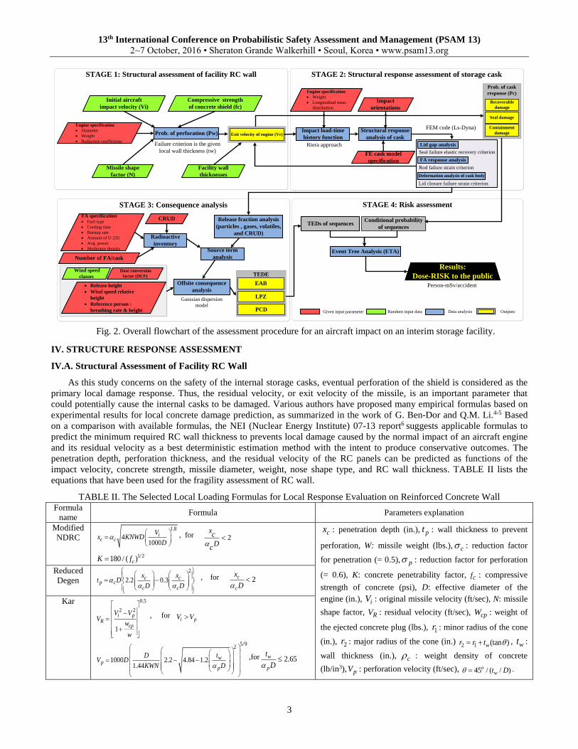
Fig. 2 shows flowchart of the proposed risk assessment procedure of an ISF in an AI event. The procedure is composed
of four integrated stages: a local structural analysis of the facility RC wall response under engine impact to evaluate the
perforation failure mode, a structural response assessment of a single storage cask to evaluate the cask damage status, the
associated consequence analysis for each impact condition, and a PSA to quantify the AI-induced risk to the public. The
quantification of the risk for the representative sets of impact conditions is given in a proposed event tree model that includes
the accident scenario as a sequence of events and the probability of each sequence, as illustrated at the end of this paper.
3
1
2
4
5
1
Freestanding storage cask assembly
Case 1 - lateral impact on
the lower half of the cask;
Case 2 - lateral impact on
the center of gravity;
Case 3 - lateral impact on
the upper half of the cask;
Case 4 - Inclined impact on an upper corner of the
cask;
Case 5 - Vertical impact
on the center of the lid
closure
1
2
3
4
5
13th International Conference on Probabilistic Safety Assessment and Management (PSAM 13)
2~7 October, 2016 • Sheraton Grande Walkerhill • Seoul, Korea • www.psam13.org
3
STAGE 1: Structural assessment of facility RC wall STAGE 2: Structural response assessment of storage cask
STAGE 3: Consequence analysis STAGE 4: Risk assessment
Prob. of cask
response (Pc)
Exit velocity of engine (Vr)
Recoverable
damage
Seal damage
Containment
damageProb. of perforation (Pw)
Failure criterion is the given
local wall thickness (tw)
Gaussian dispersion
model
Given input parameter Random input data Data analysis Outputs
Compressive strength
of concrete shield (fc)
Results:
Dose-RISK to the public
Initial aircraft
impact velocity (Vi)
Engine specification
Diameter
Weight
Reduction coefficients
Missile shape
factor (N)
Facility wall
thicknesses
Impact load-time
history function
Engine specification
Weight
Longitudinal mass
distribution
Impact
orientations
FE cask model
specification
Structural response
analysis of cask
Lid gap analysis
FA response analysis
Seal failure elastic recovery criterion
Rod failure strain criterion
Deformation analysis of cask body
Lid closure failure strain criterion
Release fraction analysis
(particles , gases, volatiles,
and CRUD)
Source term
analysis
CRUDFA specification Fuel type
Cooling time
Burnup rate
Amount of U-235
Avg. power
Moderator density
Radioactive
inventory
Number of FA/cask
Dose conversion
factor (DCF)
Wind speed
classes
Release height
Wind speed relative
height
Reference person :
breathing rate & height
Offsite consequence
analysis
Riera approach
FEM code (Ls-Dyna)
TEDE
EAB
LPZ
PCD
Event Tree Analysis (ETA)
Conditional probability
of sequencesTEDs of sequences
Person-mSv/accident
Fig. 2. Overall flowchart of the assessment procedure for an aircraft impact on an interim storage facility.
IV. STRUCTURE RESPONSE ASSESSMENT
IV.A. Structural Assessment of Facility RC Wall
As this study concerns on the safety of the internal storage casks, eventual perforation of the shield is considered as the
primary local damage response. Thus, the residual velocity, or exit velocity of the missile, is an important parameter that
could potentially cause the internal casks to be damaged. Various authors have proposed many empirical formulas based on
experimental results for local concrete damage prediction, as summarized in the work of G. Ben-Dor and Q.M. Li.4-5 Based
on a comparison with available formulas, the NEI (Nuclear Energy Institute) 07-13 report6 suggests applicable formulas to
predict the minimum required RC wall thickness to prevents local damage caused by the normal impact of an aircraft engine
and its residual velocity as a best deterministic estimation method with the intent to produce conservative outcomes. The
penetration depth, perforation thickness, and the residual velocity of the RC panels can be predicted as functions of the
impact velocity, concrete strength, missile diameter, weight, nose shape type, and RC wall thickness. TABLE II lists the
equations that have been used for the fragility assessment of RC wall.
TABLE II. The Selected Local Loading Formulas for Local Response Evaluation on Reinforced Concrete Wall Formula
name Formula Parameters explanation
Modified
NDRC
1.8
41000
ic c
Vx KNWD
D
, for 2xc
Dc
1/2180 / ( )cK f
cx : penetration depth (in.), pt : wall thickness to prevent
perforation, W: missile weight (lbs.), c : reduction factor
for penetration (= 0.5), p : reduction factor for perforation
(= 0.6), K: concrete penetrability factor, cf : compressive
strength of concrete (psi), D: effective diameter of the
engine (in.), iV : original missile velocity (ft/sec), N: missile
shape factor, RV : residual velocity (ft/sec), cpW : weight of
the ejected concrete plug (lbs.), 1r : minor radius of the cone
(in.), 2r : major radius of the cone (in.) 2 1 (tan )wr r t , wt :
wall thickness (in.), c : weight density of concrete
(lb/in3), pV : perforation velocity (ft/sec), 45 / ( / )owt D .
Reduced
Degen
2
2.2 0.3c cp c
c c
x xt D
D D
, for 2c
c
x
D
Kar 0.5
2 2
1
i pR
cp
V VV
w
w
, for i pV V
5/92
1000 2.2 4.84 1.21.44
wp
p
tDV D
KWN D
,for 2.65w
p
t
D

13th International Conference on Probabilistic Safety Assessment and Management (PSAM 13)
2~7 October, 2016 • Sheraton Grande Walkerhill • Seoul, Korea • www.psam13.org
4
AI speed, concrete strength, facility wall thickness, and the missile shape factor parameters are considered as major
sources of uncertainty. The AI speed is dependent on many factors such as the size of the target, topography around the site,
weather, payload, pilot skills, etc. The facility wall varies from location to location in the thickness of the sidewall, corners,
and roof of the building structure. The properties of the RC wall vary from batch to batch fabrication and according to aging
effects. From the literature, the aircraft speed is assumed to be normally distributed with a mean of 155 m/s and standard
deviation 35.24, and the wall thickness also is assumed to be normally distributed with a mean of 95 cm and standard
deviation 6.86. The nose shape factor N ranges from 0.72 for flat-nosed to 1.14 for very sharp missiles.3 In this study, N is
assumed to be normally distributed with a mean value of 0.93 and standard deviation 0.05. The compressive strength of
concrete fc is modeled as a logarithmic normal distribution, typically used in civil engineering applications. The mathematical
model of the probability density function of the concrete strength, as proposed by A. Ö ztemel, for different concrete classes is
shown in Fig. 3.7
From Fig. 3, fc is defined as the strength of a single sample, and fck is the characteristic strength defined as the value of
material strength below which not more than a minimally acceptable percentage of the test results are expected to fall. The
coefficient of percent deviation from the characteristic strength value is 1.28143, and 28.11 is the generalized variance of the
non-logarithmized sample values. μ and σ are called the location parameter and the scale parameter, respectively. The
conditional probability of perforation for a given thickness is estimated by using the Monte-Carlo simulation method, which
sets random data variables in their individual probability density functions. Then each set is employed as an input data for
separate deterministic runs. The obtained distribution curves for the residual velocity variables from the equations in TABLE
II are shown in Fig. 4 with respect to various concrete classes. Weibull distribution curve modelling of VR is selected because
it shows a good fit based on a normality test, and the random variable values of the residual velocity are positive.
Fig. 3. Logarithmic normal distribution model for
uncertainty in the compressive strength of concrete.
Fig. 4. Probabilistic density function curve of
residual velocity for the engine.
Fig. 5. Cumulative distribution curve for perforation
thickness.
Fig. 6. Estimated conditional probability of
perforation for various concrete wall thicknesses.

13th International Conference on Probabilistic Safety Assessment and Management (PSAM 13)
2~7 October, 2016 • Sheraton Grande Walkerhill • Seoul, Korea • www.psam13.org
5
The cumulative distribution function for perforation thickness is generated based on 10,000 trials as shown in Fig. 5. The
failure probability, or perforation damage mode, of a given wall thickness can be calculated from the complementary
cumulative distribution function of Fig. 5 as shown in Fig. 6. Considering several wall thicknesses and concrete classes from
Fig. 6, the average failure probability of the facility walls Pw equals 0.662.
IV.B. Structural Response Assessment of Storage Cask
A series of explicit non-linear dynamic analyses of a single freestanding storage cask under engine impact load is
performed using the commercially available finite element code Ls-Dyna. The time history function of a turbojet engine is
derived by utilizing the proposed curve from CRIEPI (Central Research Institute of Electric Power Industry; Tokyo, Japan)
for a detailed model of the aircraft engine CF6-80C28 and then scaled to other higher impact velocities based on the Riera
approach, 9 which is widely used in aircraft crash analyses. The approach is described in the following iterative algorithm: 2( ) ( ) [ ( )] ( )F t P x x t v t (1)
( ) [ ( )]dv
P x M m xdt
(2)
where F(t) is the engine impact force, and P(x) is the crushing force that induces instantaneous and homogenous deceleration
dv/dt in the remaining uncrushed part of the engine. This deceleration dv/dt from the destruction of the whole B747 equals
29.98 m/s2 (Ref. 10). M is the total engine mass, μ[x(t)] is the longitudinal mass distribution, m(x) is the mass of the crushed
portion, and v(t) is the impact velocity of the uncrushed portion of the engine ( ( ) iv t v v , v dv dt t ). Fig. 7 shows
the impact force time-history curves that have been obtained by the above equations for the several selected impact velocities.
Fig. 7. Scaled impact load-time history curves of engine model GE/CF6-80C2 for various impact.
The cask impact orientation is specified by the angle between the cask axis and the engine axis. It is assumed that the
lateral impacts, corner impact, and vertical impact would be between 0 and 20 degrees, 20 and 70 degrees, and 70 and 90
degrees, respectively. Justifying the probability of each scenario based on physical and practical sense is considered difficult
due to the complexity of an aircraft crash. Therefore, it is assumed that the impacts at all angles are equally probable, and
therefore are presented in an even distribution. Moreover, vulnerable impact areas on the cask body are divided into three
areas: lateral (60%), corner (20%), and vertical (20%). Therefore, the impact orientation probabilities (Po) of lateral, corner,
and vertical impacts for the five defined impact areas are as follows: Po_lat=(20/90× 0.6)=0.13, Po_cor =(50/90× 0.2)=0.11,
Po_ver =(20/90× 0.2)=0.04.
The lid seal plays an essential role in preventing the escape of fine particulates and radioactive gases from the cask
following an accident. The finite element model aims to analyze the dynamic response of the lid closure system to calculate
the leakage path area between the lid and the flange. Therefore, investigating the plastic strain on the bolts, the O-ring seal,
and the region around them is important to define the cask failure criteria due to engine impact. It is assumed that a closure
opening greater than the pre-compression of the metallic seal (elastic recovery er = 0.25 mm) will cause a leakage.11 Fig. 8
shows an isometric view for the cask components that are employed in the analysis and a representative seal region for
calculating lid gaps along the lid closure. Through the numerical analysis, three cask response statuses are defined and
categorized as follows: recoverable damage (RD) when the O-ring seal successfully recovers the generated gaps (< er); seal
damage (SD) when the opening gaps exceed the elastic recovery distance (> er); and containment damage (CD) when an
irreversible deformation occurs on the cask containment. TABLE III shows the status of the cask for each selected impact
condition. A detailed description about the evaluating of storage cask structural response under various engine impact
conditions has been presented in the previous work of B. Almomani.12

13th International Conference on Probabilistic Safety Assessment and Management (PSAM 13)
2~7 October, 2016 • Sheraton Grande Walkerhill • Seoul, Korea • www.psam13.org
6
Fig. 8. Finite element model of the lid closure system.
TABLE III. Cask Status Results for Each Impact Condition
Case No. Impact velocity (m/s)
40 60 80 100 120 140 160
Case 1
Recoverable damage
Recoverable
damage
Recoverable
damage
Recoverable damage Recoverable
damage
Recoverable damage
Seal damage Case 2 Seal damage
Case 3
Case 4 Seal damage Containment
damage Containment damage
Containment
damage Case 5 Seal damage Seal damage Containment damage
a) Cask recoverable damage probability (Pc_rd) (b) Cask seal damage probability (Pc_sd) (c) Cask containment damage probability (Pc_cd)
Fig. 9. Cask damage probabilities as a function of facility concrete strength and impact location.
Probabilities of the impact conditions generating leak path areas that lead to consequences with magnitude (C) are
expressed for the three cask damage response modes, shown in Fig. 9. These probabilities were estimated by integrating the
area under the residual velocity curves, mentioned in Fig. 4, with the defined boundary criteria in TABLE IV. The average
failure probability of the cask for each impact case considering different concrete strengths is given in TABLE IV.
TABLE IV. Conditional Probability Calculations for the Cask Response Status
Boundary criteria (m/s) State Pc
Case 1 V V140 rd 0.999883
V140 V V160 sd 0.000117
Case 2 V V120 rd 0.993323
V120 V V160 sd 0.00662
Case 3 V V120 rd 0.993323
V120 V V160 sd 0.00662
Case 4
V V80 rd 0.848097
V80 V V100 sd 0.109633
V100 V V160 cd 0.042208
Case 5
V V40 rd 0.316112
V40 V V80 sd 0.528655
V80 V V160 cd 0.151823
Cask
body Interior body
Cask lid Bolt Lid gap analysis area
13th International Conference on Probabilistic Safety Assessment and Management (PSAM 13)
2~7 October, 2016 • Sheraton Grande Walkerhill • Seoul, Korea • www.psam13.org
7
V. SOURCE TERM AND OFF-SITE CONSEQUENCE ANALYSIS
V.A. Structural Response Assessment of Storage Cask
In order to examine the radiological consequences, an associated radioactive material release evaluation to the
environment is estimated from the cask release fraction and the source term (STi) for radionuclide i that can be approximated
by Eqs. (3-4) as follows: 13
Frel,k = [RFC-E × RF] × RFR-C × FDR × LPF (3)
, ,
,
i i k rel k
i k
ST I F (4)
where Ii,k represents the quantity of spent fuel inventory for radionuclide i in chemical form group k, Frel,k is the release
fraction of chemical form group k, RFR-C is a portion of radioactive material release from rod to cask cavity, RFC-E is a
portion of radioactive material release from cask cavity to environment, FDR is the fuel damage ratio of the assembly, and
LPF is the leak path factor representing the fraction of airborne material escaping from the containment building. LPF is
assumed as 1 since the aircraft already damaged the facility building. RF is the respirable fraction of radionuclide particles.
Eqs. (3-4) were analyzed separately for each group of similar radioactive materials. The radioactive material inventory
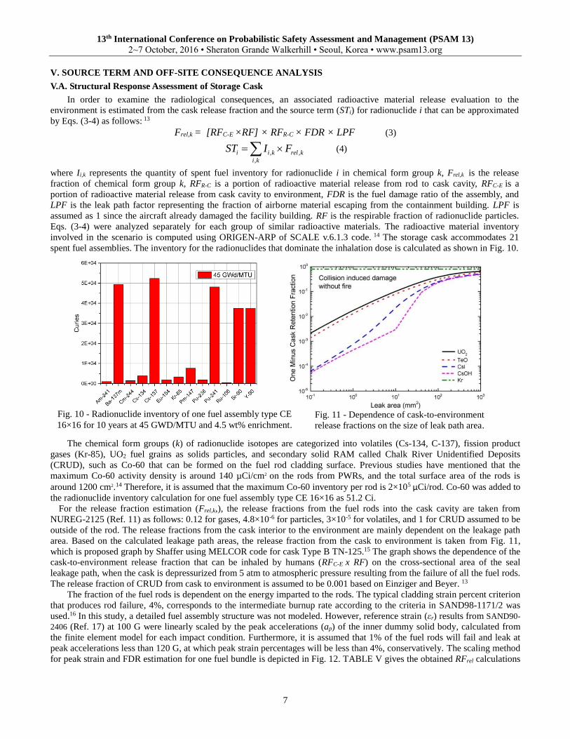
involved in the scenario is computed using ORIGEN-ARP of SCALE v.6.1.3 code. 14 The storage cask accommodates 21
spent fuel assemblies. The inventory for the radionuclides that dominate the inhalation dose is calculated as shown in Fig. 10.
The chemical form groups (k) of radionuclide isotopes are categorized into volatiles (Cs-134, C-137), fission product
gases (Kr-85), UO2 fuel grains as solids particles, and secondary solid RAM called Chalk River Unidentified Deposits
(CRUD), such as Co-60 that can be formed on the fuel rod cladding surface. Previous studies have mentioned that the
maximum Co-60 activity density is around 140 µCi/cm2 on the rods from PWRs, and the total surface area of the rods is
around 1200 cm2.14 Therefore, it is assumed that the maximum Co-60 inventory per rod is 2×10⁵ µCi/rod. Co-60 was added to
the radionuclide inventory calculation for one fuel assembly type CE 16×16 as 51.2 Ci.
For the release fraction estimation (Frel,k,), the release fractions from the fuel rods into the cask cavity are taken from
NUREG-2125 (Ref. 11) as follows: 0.12 for gases, 4.8×10⁻⁶ for particles, 3×10⁻⁵ for volatiles, and 1 for CRUD assumed to be
outside of the rod. The release fractions from the cask interior to the environment are mainly dependent on the leakage path
area. Based on the calculated leakage path areas, the release fraction from the cask to environment is taken from Fig. 11,
which is proposed graph by Shaffer using MELCOR code for cask Type B TN-125.15 The graph shows the dependence of the
cask-to-environment release fraction that can be inhaled by humans (RFC-E x RF) on the cross-sectional area of the seal
leakage path, when the cask is depressurized from 5 atm to atmospheric pressure resulting from the failure of all the fuel rods.
The release fraction of CRUD from cask to environment is assumed to be 0.001 based on Einziger and Beyer. 13
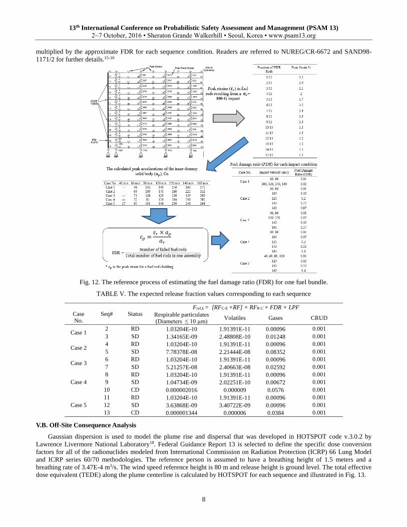
The fraction of the fuel rods is dependent on the energy imparted to the rods. The typical cladding strain percent criterion
that produces rod failure, 4%, corresponds to the intermediate burnup rate according to the criteria in SAND98-1171/2 was
used.16 In this study, a detailed fuel assembly structure was not modeled. However, reference strain (εr) results from SAND90-
2406 (Ref. 17) at 100 G were linearly scaled by the peak accelerations (ap) of the inner dummy solid body, calculated from
the finite element model for each impact condition. Furthermore, it is assumed that 1% of the fuel rods will fail and leak at
peak accelerations less than 120 G, at which peak strain percentages will be less than 4%, conservatively. The scaling method
for peak strain and FDR estimation for one fuel bundle is depicted in Fig. 12. TABLE V gives the obtained RFrel calculations
Fig. 10 - Radionuclide inventory of one fuel assembly type CE
16×16 for 10 years at 45 GWD/MTU and 4.5 wt% enrichment. Fig. 11 - Dependence of cask-to-environment
release fractions on the size of leak path area.
13th International Conference on Probabilistic Safety Assessment and Management (PSAM 13)
2~7 October, 2016 • Sheraton Grande Walkerhill • Seoul, Korea • www.psam13.org
8
multiplied by the approximate FDR for each sequence condition. Readers are referred to NUREG/CR-6672 and SAND98-
1171/2 for further details.15-16
Fig. 12. The reference process of estimating the fuel damage ratio (FDR) for one fuel bundle.
TABLE V. The expected release fraction values corresponding to each sequence
V.B. Off-Site Consequence Analysis
Gaussian dispersion is used to model the plume rise and dispersal that was developed in HOTSPOT code v.3.0.2 by
Lawrence Livermore National Laboratory18. Federal Guidance Report 13 is selected to define the specific dose conversion
factors for all of the radionuclides modeled from International Commission on Radiation Protection (ICRP) 66 Lung Model
and ICRP series 60/70 methodologies. The reference person is assumed to have a breathing height of 1.5 meters and a
breathing rate of 3.47E-4 m3/s. The wind speed reference height is 80 m and release height is ground level. The total effective
dose equivalent (TEDE) along the plume centerline is calculated by HOTSPOT for each sequence and illustrated in Fig. 13.
Case No.
Seq# Status Frel,k = [RFC-E × RF] × RFR-C × FDR × LPF
Respirable particulates (Diameters ≤ 10 µm)
Volatiles Gases CRUD
Case 1 2 RD 1.03204E-10 1.91391E-11 0.00096 0.001
3 SD 1.34165E-09 2.48808E-10 0.01248 0.001
Case 2 4 RD 1.03204E-10 1.91391E-11 0.00096 0.001
5 SD 7.78378E-08 2.21444E-08 0.08352 0.001
Case 3 6 RD 1.03204E-10 1.91391E-11 0.00096 0.001
7 SD 5.21257E-08 2.40663E-08 0.02592 0.001
Case 4
8 RD 1.03204E-10 1.91391E-11 0.00096 0.001
9 SD 1.04734E-09 2.02251E-10 0.00672 0.001
10 CD 0.000002016 0.000009 0.0576 0.001
Case 5
11 RD 1.03204E-10 1.91391E-11 0.00096 0.001
12 SD 3.63868E-09 3.40722E-09 0.00096 0.001
13 CD 0.000001344 0.000006 0.0384 0.001

13th International Conference on Probabilistic Safety Assessment and Management (PSAM 13)
2~7 October, 2016 • Sheraton Grande Walkerhill • Seoul, Korea • www.psam13.org
9
Fig. 13. The calculated total effective dose equivalent along the plume centerline (mSv)
VI. RISK ASSESSMENT
In this study, the initiating event frequency of an AI is assumed to be one since the success of an aircraft crash on a target
object depends on many unforeseen factors that cannot be measured. The elements of the dose-risk (person-mSv/accident) for
this study are the product of the probabilities of each impact condition and corresponding response (Pw, Po, and Pc), and the
fractions that lead to the release of RAM which cause consequences of magnitude (C). The measure of risk is given by Eq. 5
that is applied in sequence line i:
i w o ci iR P P P C (5)
The risk calculations are summarized in the event tree for the three site boundaries of interest: EAB, LPZ, and the PCD
as shown in Fig. 14. Because all off-site release results in doses to individuals are below the public exposure limitation, no
prompt severe risk from a single storage cask is expected.
Fig. 14. Event tree of probability, consequence, and risk estimation (person-mSv/accident) from 1 storage cask at three site
boundaries: a) Exclusive area boundary (EAB), b) Low population zone (LPZ), c) Population center distance (PCD)
(c) PCD at 7.6 km
(b) LPZ at 5.7 km
(a) EAB at 560 m
13th International Conference on Probabilistic Safety Assessment and Management (PSAM 13)
2~7 October, 2016 • Sheraton Grande Walkerhill • Seoul, Korea • www.psam13.org
10
VII. CONCLUSIONS
This paper proposed an assessment framework for an aircraft crash scenario with focus on the direct mechanical impact
onto a dry spent fuel storage system. The scope of the study includes estimating the structural failure probabilities of the
facility shield and the storage cask, with the release of radioactive material from the spent fuel. The leak path areas from the
lid closure were numerically calculated. The release fraction and fuel damage ratios were calculated for different impact
conditions to estimate the possible source terms for this case study. Using a quantitative event tree analysis, the individual
risk for each possible sequence was obtained. The quantitative analysis results have indicated that the proposed framework
here successfully evaluated a possible aircraft crash scenario and is expected to provide useful information for regulators and
licensees concerning the most severe impact condition. From the analysis, the engine impact on a single fully loaded storage
cask did not cause a radiological impact that exceeds regulatory limits. From the overall risk assessment of the case study, it
is found that an impact on the cask upper corner poses a relatively significant risk. The introduced risk model in this study
can be used with any other representative detailed parameters and reference models for other comparable direct or indirect
impact conditions onto the cask body, which may provide an efficient way to investigate the ISF capacity to withstand an
aircraft crash and thereby protect public health.
ACKNOWLEDGMENTS
This work was supported by the Nuclear Safety Research Program through the Korea Foundation of Nuclear Safety
(KOFONS), granted financial resource from the Nuclear Safety and Security Commission (NSSC), Republic of Korea
(No.1305032).
REFERENCES
1. EPRI NP-3365, Review of Proposed Dry-Storage Concepts Using Probabilistic Risk Assessment, NUS corporation
(1984).
2. NUREG-1864, A Pilot Probabilistic Risk Assessment of a Dry Cask Storage System at A Nuclear Power Plant, U.S.
NRC (2007).
3. DOE- STD-3014, Accident Analysis for Aircraft Crash into Hazardous Facilities, US-DOE Standards (2006).
4. G. BEN-DOR, A. DUBINSKY, T. ELPERIN, “Empirical models for predicting protective properties of concrete shields
against high-speed impact”, J. of Mech. of Mater. and Struct., 8, 2-4 (2013).
5. LI, Q. M., REID, S. R., WEN, H. M., & TELFORD, A. R., “Local impact effects of hard missiles on concrete
targets”. Int. J. of Impact Eng., 32, 224-284 (2005).
6. NEI 07-13, Methodology for Performing Aircraft Impact Assessments for New Plant Designs, NEI (2011).
7. A. Ö ZTEMEL, S. ŞENSOY, “Mathematical Model for the Probability Distribution of In-Situ Concrete Compressive
Strength in North Cyprus”, 29th Conference on our World in Concrete & Structures, 387-395, (2004).
8. K. SHIRAI, K. NAMBA, and T. SAEGUSA, “Safety analysis of dual purpose metal cask subjected to impulsive loads
due to aircraft engine crash, J. of Power and Energy Systems, 3, 72-82, (2009).
9. J. D. RIERA, “On the Stress Analysis of Structures Subjected to Aircraft Impact Forces”, Nucl. Eng. and Des., 415-426,
(1968).
10. V. ILIEV, K. GEORGIEV, V. SERBEZOV, “Assessment of Impact Load Curve of Boeing 747-400”, J. of Science,
Techniques and Innovations for The Industry “Machines, Technologies, Materials” (2011).
11. NUREG-2125, Spent Fuel Transportation Risk Assessment, U.S. Nuclear Regulatory Commission (2012).
12. B. ALMOMANI, S. LEE, H.G. KANG, “Structural analysis of a metal spent-fuel storage cask in an aircraft crash for
risk assessment”, Nucl. Eng. and Des., accepted (2016).
13. R. E. EINZIGER, and C. BEYER, “Characteristics and Behavior of High-Burnup Fuel That May Affect the Source
Terms for Cask Accidents”, Nuclear technology, 159.2, 134-146 (2007).
14. GAULD, I.C., BOWMAN, S.M., HORWEDEL, J.E, ORIGEN-ARP: Automatic rapid processing for spent fuel
depletion, decay, and source term analysis, ORNL/TM- 2005/39. ORNL, USA (2006). 15. NUREG/CR-6672, Reexamination of Spent Fuel Shipment Risk Estimates, Sandia National Laboratory, U.S. Nuclear
Regulatory Commission (2000).
16. SAND98-1171/2, Data and Methods for Assessment of the Risks Associated with The Maritime Transport of Radioactive
Materials Results of the SeaRAM Program Studies, Sandia National Laboratories (1998).
17. SAND90-2406, A Method for Determining the Spent-Fuel Contribution to Transport Cask Containment Requirements,
Sandia National Laboratories (1992).
18. HOMANN, S.G., 2010. HotSpot – Health Physics Codes -Version 2.07 1-User’s Guide, LLNL.


![Itil Problem Management Report6[1]](https://img.pdfslide.us/doc/110x75/53fce490dab5ca94038b49f9/itil-problem-management-report61.jpg)