Embed Size (px)
Citation preview

Probabilistic Risk Assessment
- Introduction
- Methodology and Preliminary Results of
Level 1 Internal Events PRA
Mee
tin
g
Level 1 Internal Events PRA
- Methodologies and Status of PRAs for
ion
Rev
iew
M
External Events and Low Power Shutdown Modes
Pre
-ap
pli
cati
APR1400‐E‐P‐EC‐12003‐NP
7th
P

PRA
Regulatory Requirement for PRAegu ato y equ e e t o
● PRA10 CFR 52 47 LICENSES CERTIFICATIONS AND APPROVALS FOR− 10 CFR 52.47 LICENSES, CERTIFICATIONS, AND APPROVALS FOR NUCLEAR POWER PLANTS (a) … must include the following information:
(27) A description of the design specific probabilistic risk– (27) A description of the design specific probabilistic risk assessment (PRA) and its results.
− RG 1.206 COMBINED LICENSE APPLICATIONS FOR NUCLEAR POWER PLANTS
Mee
tin
g
C.I.19 PROBABILITY RISK ASSESSMENT AND SEVERE ACCIDENT EVALUATION
To provide prospective COL applicants with guidance concerning the format
ion
Rev
iew
M
p p p pp g gand content of the application
Pre
-ap
pli
cati
APR1400‐E‐P‐EC‐12003‐NP
7th
P
1

PRA
Regulatory Requirement & Guidelineegu ato y equ e e t & Gu de e
● PRA Scope and QualitySRP 19 0− SRP 19.0
− SRP 19.1− DC/COL-ISG-03
RG 1 200 R 2− RG 1.200 Rev. 2− ASME/ANS RA-Sa-2009 PRA Standards− RG 1.174 Rev . 1
Mee
tin
gio
n R
evie
w M
Pre
-ap
pli
cati
APR1400‐E‐P‐EC‐12003‐NP
7th
P
2

PRA
Purpose of APR1400 PRAu pose o 00
● To meet 10 CFR 52.47 (a) (27).● To demonstrate that the risk associated with the design is
acceptably low compared to the Commission’s goals.● To identify and address potential design and operational y p g p
vulnerabilities.
Mee
tin
gio
n R
evie
w M
Pre
-ap
pli
cati
APR1400‐E‐P‐EC‐12003‐NP
7th
P
3

PRA
APR1400 PRA Scope00 Scope
Internal Events O
At-powerOInternal Fire O
Internal Flooding O
Mee
tin
g
Seismic* O -
Internal Events O O
ion
Rev
iew
M Low Power and Shutdown
Internal Fire △ △
Internal Flooding △ △
Pre
-ap
pli
cati
* ) PRA-based SMA, △) Qualitative approach
APR1400‐E‐P‐EC‐12003‐NP
7th
P
4

PRA
APR1400 PRA History00 sto y
• Upgrade PRA method & data
System80+ PRA
APR1400 PRA
APR1400 PRA
Mee
tin
g
PRA
(1997)
PRA
(2002)PRA
(NRC DC)
ion
Rev
iew
M
SKN3&4 PRA
• Detail DesignInformation
Pre
-ap
pli
cati PRA
(2011)
APR1400‐E‐P‐EC‐12003‐NP
7th
P
5
PRA
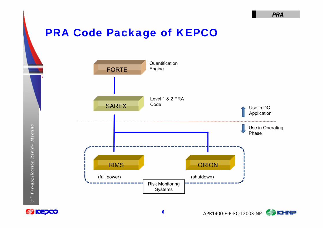
PRA Code Package of KEPCO
Q tifi ti
Code ac age o CO
FORTEQuantificationEngine
SAREXLevel 1 & 2 PRA Code
Use in DC Application
Mee
tin
g
Application
Use in Operating Phase
ion
Rev
iew
M
RIMS ORION
Pre
-ap
pli
cati RIMS ORION
(full power) (shutdown)Risk Monitoring
Systems
APR1400‐E‐P‐EC‐12003‐NP
7th
P
6
y

PRA
PRA Code Package of KEPCOCode ac age o CO
● FORTEPRA Q tifi ti E i− PRA Quantification Engine
− Support compatible input & output formats Input : FTAP, SET
O t t EPRI R&R W/S Std (RAW) T t f t Output : EPRI R&R W/S Std. (RAW), Text format.
● SAREX− Integrated Level 1/2 PRA Code Package
Mee
tin
g
− Main Modules Fault Tree Analyzer (FTA) DataBase Analyzer (DBA)
ion
Rev
iew
M
y ( ) Event Tree Analyzer (ETA) : L1 & L2 CutSet Analyzer (CSA) ReCovery Analyzer (RCA)
Pre
-ap
pli
cati
y y ( ) Uncertainty Analyzer (UNCA)
APR1400‐E‐P‐EC‐12003‐NP
7th
P
7

Level 1 Internal Events Analysis
- MethodologyMethodology
- Preliminary Results
on
Mee
tin
gre
-ap
pli
cati
o7
thP
r

PRA
Methodologyet odo ogy
● NUREG/CR-2300, "PRA Procedures Guide"G/C 281 S f● NUREG/CR-2815, "Probabilistic Safety Analysis Procedures
Guide" ● ASME/ANS RA-Sa-2009 “PRA Standards”
Mee
tin
gio
n R
evie
w M
Pre
-ap
pli
cati
APR1400‐E‐P‐EC‐12003‐NP
7th
P
9

PRA
Initiating Events of APR1400t at g e ts o 00
Category Events1. Large Loss of Coolant Accident (LLOCA)
Loss of Coolant Accident
1. Large Loss of Coolant Accident (LLOCA)2. Medium Loss of Coolant Accident (MLOCA)3. Small Loss of Coolant Accident (SLOCA)4. Steam Generator Tube Rupture (SGTR)5. Interfacing System LOCA (ISLOCA)5. Interfacing System LOCA (ISLOCA)6. Reactor Vessel Rupture (RVR)7. Large Secondary Side Breaks (upstream of MSIV) (MSLBU)8. Large Secondary Side Breaks (downstream of MSIV) (MSLBD)9. Loss of Main Feedwater Transients (LOFW)
Mee
tin
g
9. Loss of Main Feedwater Transients (LOFW)10. Feedwater Line Break (FWLB)11. Loss of Instrumentation Air (LOIA)12. Loss of Condenser Vacuum (LOCV)13 Loss of Class1E 125VDC Vital Bus A (LODCA)
ion
Rev
iew
M
Transient Accident
13. Loss of Class1E 125VDC Vital Bus A (LODCA)14. Loss of Class1E 125VDC Vital Bus B (LODCB)15. Partial loss of Component Cooling Water (CCW Div. A) (PLOCCW)16. Total loss of Component Cooling Water (CCW Div. A & B) (LOCCW)17 Partial loss of Essential Service Water (ESW Div A) (PLOESW)
Pre
-ap
pli
cati 17. Partial loss of Essential Service Water (ESW Div. A) (PLOESW)
18. Total loss of Essential Service Water (ESW Div. A & B) (LOESW)19. Loss of Offsite Power (LOOP)20. Station Blackout (SBO)21 General Transients (TRAN)
APR1400‐E‐P‐EC‐12003‐NP
7th
P
10
21. General Transients (TRAN)22. Anticipated Transients Without Scram (ATWS)

PRA
Initiators not includedt ato s ot c uded
● LOHV Loss of HVACO f 4 16● LOKV Loss of a 4.16 KV Bus
● LOAC Loss of a 120V AC Bus● LONSW Loss of Non-safety Service Water System● LONSW Loss of Non-safety Service Water System● VSLOCA Very Small LOCA
A charging pump will make up to 150 gpm.
Mee
tin
g
● MTRIP Manual Trip (Manual Shutdown) Assumed to be bounded by General Transient
ion
Rev
iew
MP
re-a
pp
lica
ti
APR1400‐E‐P‐EC‐12003‐NP
7th
P
11

PRA
Accident Sequence Analysiscc de t Seque ce a ys s
● Success CriteriaD fi iti f C D− Definition of Core Damage Consistent with ASME/ANS PRA Standards: Peak node temperature
exceeds 1204°C (2200°F)Based on design basis analysis or best estimate analysis− Based on design basis analysis or best estimate analysis Utilize MAAP 4.0.8 , RELAP5 mod3, and safety analysis code Review FSAR Chapter 15
Mee
tin
g ● Event Tree Development− Small Event Tree/Large Fault Tree
ion
Rev
iew
M − Fault Trees are linked to Event Trees
Pre
-ap
pli
cati
APR1400‐E‐P‐EC‐12003‐NP
7th
P
12

PRA
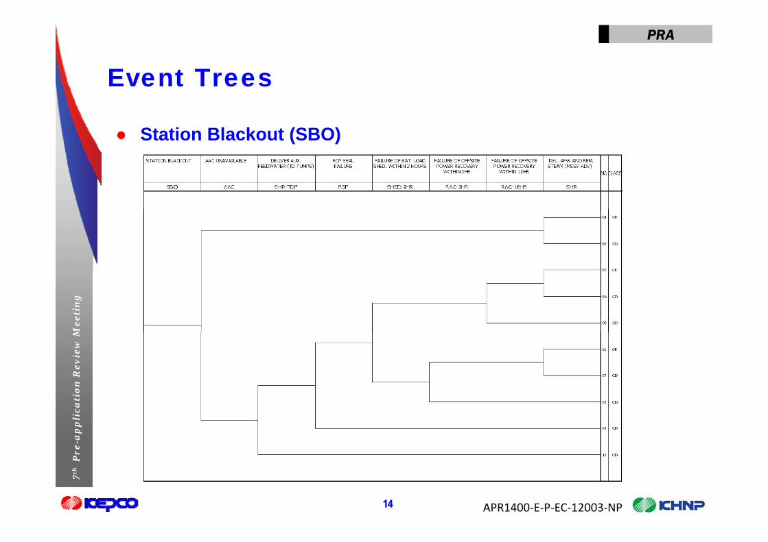
Event Treese t ees
● Loss of Offsite Power (LOOP)( )
Mee
tin
gio
n R
evie
w M
Pre
-ap
pli
cati
APR1400‐E‐P‐EC‐12003‐NP
7th
P
13
PRA
Event Treese t ees
● Station Blackout (SBO)
Mee
tin
gio
n R
evie
w M
Pre
-ap
pli
cati
APR1400‐E‐P‐EC‐12003‐NP
7th
P
14

PRA
Event Treese t ees
● Medium Loss of Coolant Accident (MLOCA)
Mee
tin
gio
n R
evie
w M
Pre
-ap
pli
cati
APR1400‐E‐P‐EC‐12003‐NP
7th
P
15

PRA
Event Treese t ees
● Total Loss of Component Cooling Water (TLOCCW)p g ( )
Mee
tin
gio
n R
evie
w M
Pre
-ap
pli
cati
APR1400‐E‐P‐EC‐12003‐NP
7th
P
16

PRA
Dataata
● Initiating Events“I iti ti E t D t h t U d t 2010” *− “Initiating Event Datasheet Update 2010” *
NUREG/CR-6890, “Reevaluation of Station Blackout Risk at Nuclear Power Plants”
NUREG/CR 6928 “Industry Average Performance for Components and NUREG/CR-6928, Industry-Average Performance for Components and Initiating Events at U.S. Commercial Nuclear Plants”
NUREG-1829, “Estimating Loss-of-Coolant Accident(LOCA) Frequencies through the Elicitation Process” Component Reliability Data
Mee
tin
g
through the Elicitation Process Component Reliability Data− “Component Reliability Data Sheets Update 2010” *
● Component Unavailability due to Test & Maintenance“C t A il bilit D t Sh t U d t 2010” *
ion
Rev
iew
M − “Component Availability Data Sheets Update 2010”
*http://nrcoe.inel.gov/resultsdb/publicdocs/AvgPerf/ComponentReliabilityDataSheets
Pre
-ap
pli
cati 2010.pdf
APR1400‐E‐P‐EC‐12003‐NP
7th
P
17
PRA
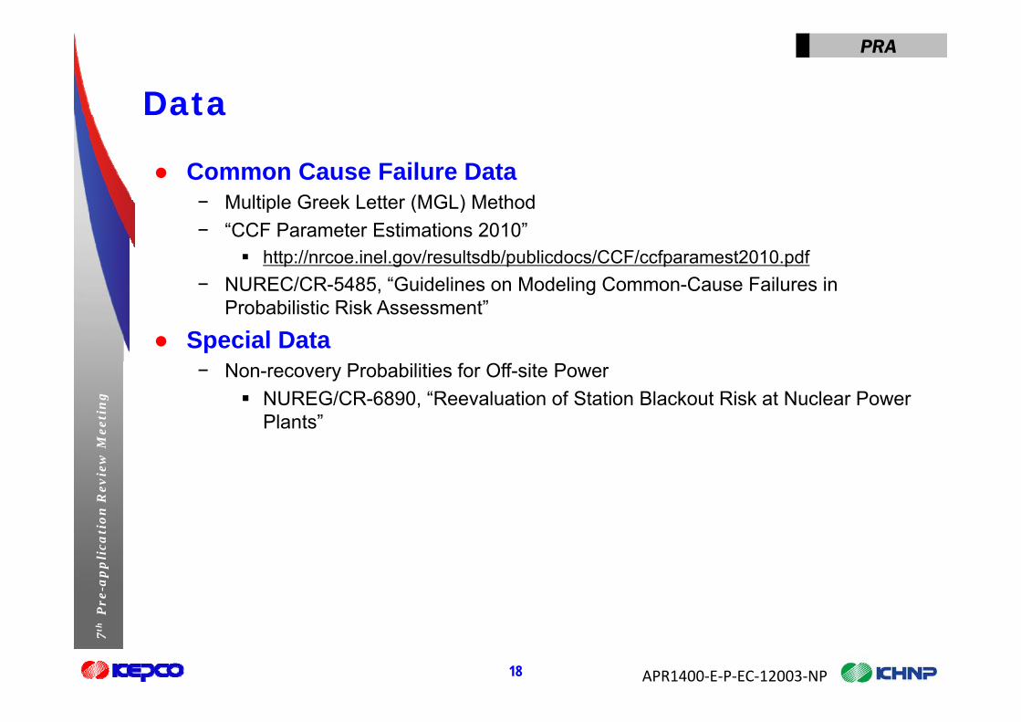
Dataata
● Common Cause Failure DataM lti l G k L tt (MGL) M th d− Multiple Greek Letter (MGL) Method
− “CCF Parameter Estimations 2010” http://nrcoe.inel.gov/resultsdb/publicdocs/CCF/ccfparamest2010.pdf
NUREC/CR 5485 “G id li M d li C C F il i− NUREC/CR-5485, “Guidelines on Modeling Common-Cause Failures in Probabilistic Risk Assessment”
● Special Data
Mee
tin
g
− Non-recovery Probabilities for Off-site Power NUREG/CR-6890, “Reevaluation of Station Blackout Risk at Nuclear Power
Plants”
ion
Rev
iew
MP
re-a
pp
lica
ti
APR1400‐E‐P‐EC‐12003‐NP
7th
P
18

PRA
Human Reliability Analysis (HRA)u a e ab ty a ys s ( )
● Pre-InitiatorASEP HRA P d (NUREG/CR 4772)− ASEP HRA Procedure (NUREG/CR-4772)
● Post-Initiator− Cause Based Decision Tree Methodology (CBDTM) or Human Cognitive
Reliability Operator Response Experiment (HCR/ORE) for Cognitive errors evaluation
− THERP (NUREG/CR-1278) for execution error evaluation
Mee
tin
gio
n R
evie
w M
Pre
-ap
pli
cati
APR1400‐E‐P‐EC‐12003‐NP
7th
P
19

PRA
Uncertainty AnalysisU ce ta ty a ys s
● Parametric uncertaintySt t f K l d C l ti (SOKC) ill b dd d− State of Knowledge Correlation (SOKC) will be addressed.
● Modeling uncertainty− Plant-specific sources of uncertainty
Based on key assumptions− Generic sources of uncertainty
NUREG-1855, EPRI 1009652
Mee
tin
g
− Uncertainty characterization
● Selected sensitivity cases will be performed, e.g., HEPs and CCF factors
ion
Rev
iew
M CCF factors.
Pre
-ap
pli
cati
APR1400‐E‐P‐EC‐12003‐NP
7th
P
20

PRA
Design Features of APR1400es g eatu es o 00
● Reactor Coolant System Pressurizer
Reactor Coolant Pump
Mee
tin
g Steam Generator
ion
Rev
iew
MP
re-a
pp
lica
ti
Reactor VesselMain Design Parameter- Power : 4 000MWth
APR1400‐E‐P‐EC‐12003‐NP
7th
P
21
- Power : 4,000MWth
PRA
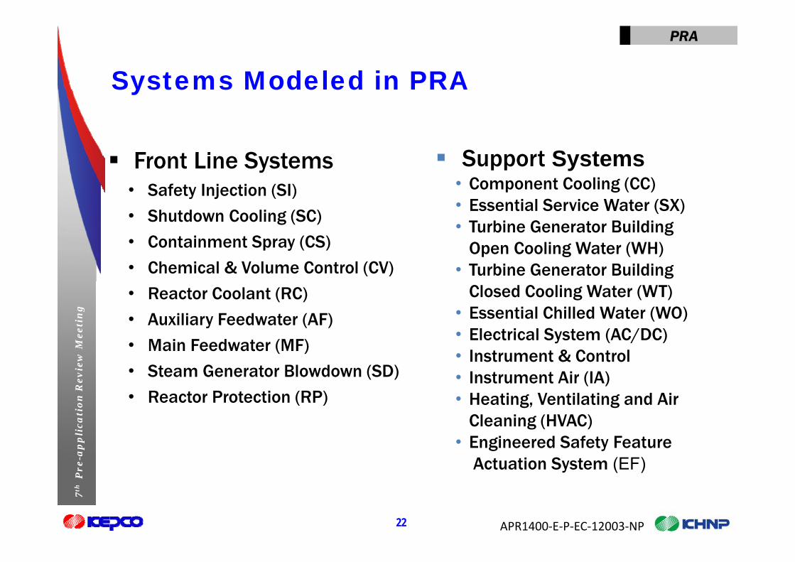
Systems Modeled in PRASyste s ode ed
F t Li S t S t S t Front Line Systems• Safety Injection (SI)
• Shutdown Cooling (SC)
Support Systems• Component Cooling (CC)• Essential Service Water (SX)• Shutdown Cooling (SC)
• Containment Spray (CS)
• Chemical & Volume Control (CV)
• Turbine Generator Building Open Cooling Water (WH)
• Turbine Generator Building
Mee
tin
g
• Reactor Coolant (RC)
• Auxiliary Feedwater (AF)
• Main Feedwater (MF)
Closed Cooling Water (WT)• Essential Chilled Water (WO)• Electrical System (AC/DC)
ion
Rev
iew
M • Main Feedwater (MF)
• Steam Generator Blowdown (SD)
• Reactor Protection (RP)
• Instrument & Control • Instrument Air (IA)• Heating, Ventilating and Air
Pre
-ap
pli
cati
Cleaning (HVAC)• Engineered Safety Feature
Actuation System (EF)
APR1400‐E‐P‐EC‐12003‐NP
7th
P
22
y ( )

PRA
Design Features of APR1400es g eatu es o 00
System or Component Configuration
Primary System
RCS2 SGs, 2 Hot Legs, 4 Cold Legs, 4 RCPs
POSRV 4
Class 1E 4.16kV Switchgears 4 trainsElectricalSystem
Class 1E 4.16kV Switchgears 4 trains
EDG 4
AAC 1
Safety Injection System 4 trains (Via DVI)
Mee
tin
g Safety System
Safety Injection Tank 4 trains (Via DVI)
Containment Spray System 2 trains
Shutdown Cooling System 2 trains (Via DVI)
IRWST 1
ion
Rev
iew
M IRWST 1
Secondary
Aux. Feedwater System 1 MDP and 1 TDP per SG
Main Steam Line 2 per SG
MSSV 10 per SG (Total 20)
Pre
-ap
pli
cati
ySystem
p ( )
MSADV 2 per SG (Total 4)
TBV 8
Supporting
APR1400‐E‐P‐EC‐12003‐NP
7th
P
23
Supporting System
ECW, CCW, ESW 2 divisions (2 trains / division)

PRA
Design Features of APR1400es g eatu es o 00
● Safety Injection System (SI)I j t b t d t i t th RCS th h Di t V l I j ti (DVI) l− Inject borated water into the RCS through Direct Vessel Injection (DVI) nozzles.
− Provide removal of heat from core for extended periods of time.− Provide feed flow for feed-and-bleed operation in conjunction with POSRVs.
− Consist of four mechanically separate trains, four SITs and associated valves, piping and instrumentation.
E h t i i t f SI d SIT
Mee
tin
g
Each train consists of one SI pump and one SIT. Each SI pump takes suction from the IRWST and discharges to DVI nozzle. Two SI pumps can inject the IRWST water to hot legs.
ion
Rev
iew
MP
re-a
pp
lica
ti
APR1400‐E‐P‐EC‐12003‐NP
7th
P
24

PRA
Design Features of APR1400es g eatu es o 00
● Containment Spray System (CS)R h t d fi i d t f t i t t h b idi− Remove heat and fission products from containment atmosphere by providing the spray flow from IRWST.
− Limit the leakage of airborne activity from the containment.
− Consist of two redundant trains.− Each train include a CS pump, a heat exchanger, a main/auxiliary spray header
with nozzle valves piping and instrumentation per train
Mee
tin
g
with nozzle, valves, piping and instrumentation per train.
ion
Rev
iew
MP
re-a
pp
lica
ti
APR1400‐E‐P‐EC‐12003‐NP
7th
P
25

PRA
Design Features of APR1400es g eatu es o 00
● Safety Depressurization and Vent System (SDVS)P id th f ll i f ti− Provide the following functions: Overpressure protection to maintain the RCS Integrity . A safety-grade means of venting non-condensable gases.
A t d i RCS f F d & Bl d ti f ll i A means to depressurize RCS for Feed & Bleed operation following LOFW.
A means to rapidly depressurize the primary system to low pressure before reactor vessel breach to prevent DCH following a severe accident
Mee
tin
g
reactor vessel breach to prevent DCH following a severe accident.− Consist of POSRVs and spargers.
ion
Rev
iew
MP
re-a
pp
lica
ti
APR1400‐E‐P‐EC‐12003‐NP
7th
P
26

PRA
Design Features of APR1400es g eatu es o 00
● Auxiliary Feedwater System (AF)P id i d d t f l i ili f d t t SG h− Provide an independent means of supplying auxiliary feedwater to SGs when the normal feedwater is unavailable.
− Provide auxiliary feedwater to each SG by one motor-driven AF pump or one turbine-driven AF pump from AFWSTturbine driven AF pump from AFWST
− Control auxiliary feedwater flow using a motor-operated AF isolation valve and a solenoid-operated AF modulating valve.
Mee
tin
gio
n R
evie
w M
Pre
-ap
pli
cati
APR1400‐E‐P‐EC‐12003‐NP
7th
P
27

PRA
Design Features of APR1400es g eatu es o 00
● Electrical SystemIt i t f f di t ib ti t i (4 it h )− It consists of four distribution trains (4 switchgears).
− Each train has a standby emergency power source supplied by an EDG.− 4 EDGs (Emergency Diesel Generators) supply emergency power to each of 1E
power distribution trainspower distribution trains− 1 AAC DG (Alternate AC Diesel Generator) can be used as a common AC
source for two Class 1E switchgears.− 4 Class 1E Batteries are provided at 125V DC power system
Mee
tin
g
− 4 Class 1E Batteries are provided at 125V DC power system.− 125V DC power source and 120V AC Instrumentation and control power system
consist of four independent and physically separated trains.
ion
Rev
iew
MP
re-a
pp
lica
ti
APR1400‐E‐P‐EC‐12003‐NP
7th
P
28

PRA
Design Features of APR1400es g eatu es o 00
● Digital I&C SystemAPR1400 control room is a highl integrated control room (HICR) that− APR1400 control room is a highly integrated control room (HICR) that includes: Operator consoles
S f t l (A l ) Safety console (Analog)− Digital I&C system is modeled on the basis of design concept of
Shin-Kori 3&4.
Mee
tin
gio
n R
evie
w M
Pre
-ap
pli
cati
APR1400‐E‐P‐EC‐12003‐NP
7th
P
29
Preliminary Results of Preliminary Results of Level 1 Internal PRA for At-Power
on
Mee
tin
gre
-ap
pli
cati
o7
thP
r

PRA
L1 PRA Preliminary Resultse a y esu tsM
eeti
ng
ion
Rev
iew
MP
re-a
pp
lica
ti
APR1400‐E‐P‐EC‐12003‐NP
7th
P
31

PRA
L1 PRA Preliminary Resultse a y esu ts
● Top 5 MCSs (%: Initiator)
NO CUTSET Description
1 %MLOCA SIOPH-S-HLI MLOCA-PLENTH-RATIO Hot Leg Injection Failure
2 %TLOESW CVOPH S RCPSEAL SEAL AFSUC RCP Seal Failure
Mee
tin
g
2 %TLOESW CVOPH-S-RCPSEAL SEAL-AFSUC RCP Seal Failure
3 %GTRN I-ATWS-RPMCF MTC-ATWS MTC Condition
ion
Rev
iew
M
4 %RVR Reactor Vessel Rupture
Pre
-ap
pli
cati
5 %TLOCCW CVOPH-S-RCPSEAL SEAL-AFSUC RCP Seal Failure
APR1400‐E‐P‐EC‐12003‐NP
7th
P
32

PRA
L1 PRA Preliminary Resultse a y esu ts
● Importance Analysis for HRA
ORDER EVENT DESCRIPTION
1 DAOPH-S-AACDG OPERATOR FAILS TO CONNECT AAC DG WITH C1E 4.16 BUS
Mee
tin
g 2 CVOPH-S-RCPSEAL OPERATOR FAILS TO RECOVER RCP SEAL COOLING (CCW CONNTECT. OR AUX. CHG PUMP)
ion
Rev
iew
M
3 SIOPH-S-HLI OPERATOR FAILS TO HOT LEG INJECTION
CO S S OOPERATOR FAILS TO SHED LOAD FOR EXTENDING
Pre
-ap
pli
cati 4 DCOPH-S-SHEDLOAD-MD BATTERY TIME
(MEDIUM DEPENDENCY WITH DAOPH-S-AACDG)
5 FWOPH-S-ERY OPERATOR FAILS TO ALIGN STARTUP FEED WATER PUMP
APR1400‐E‐P‐EC‐12003‐NP
7th
P
33
PUMP

PRA
L1 PRA Preliminary Resultse a y esu ts
● Importance Analysis for CCF
ORDER EVENT DESCRIPTION
DEMAND CCF OF ECW CHILLERS 3A/4A/3B/4B1 WOCHWQ4-CH03A/4A/3B/4B DEMAND CCF OF ECW CHILLERS 3A/4A/3B/4B FOR ESW PUMP ROOM
2 OC Q C 01 /2 /1 /2 CC O C C S 1 /2 /1 /2
Mee
tin
g
2 WOCHWQ4-CH01A/2A/1B/2B DEMAND CCF OF ECW CHILLERS 1A/2A/1B/2B
3 AFTPKD2-TDP01A/B 2/2 CCF OF RUNNING AFW TDP PP01/A/B
ion
Rev
iew
M 3 AFTPKD2-TDP01A/B 2/2 CCF OF RUNNING AFW TDP PP01/A/B
4 WOCHKQ4-CH03A/3B/4A/4B RUNNING CCF OF ECW CHILLERS 3A/4A/3B/4B FOR ESW PUMP ROOM
Pre
-ap
pli
cati FOR ESW PUMP ROOM
5 WOCHKQ4-CH01A/1B/2A/2B RUNNING CCF OF ECW CHILLERS 1A/2A/1B/2B
APR1400‐E‐P‐EC‐12003‐NP
7th
P
34

Level 1 Flooding Analysis
on
Mee
tin
gre
-ap
pli
cati
o7
thP
r

PRA
Internal Flooding PRAte a ood g
● GuidanceRG 1 200 R i i 2− RG 1.200 Revision 2
− ASME/ANS RA-Sa-2009 “PRA Standards” − SRP 19.1
EPRI 1021086 “Pi R t F i f I t l Fl di P b bili ti− EPRI 1021086 “Pipe Rupture Frequencies for Internal Flooding Probabilistic Risk Assessments” Revision 2
Mee
tin
gio
n R
evie
w M
Pre
-ap
pli
cati
APR1400‐E‐P‐EC‐12003‐NP
7th
P
36
PRA
APR1400 Characteristics00 C a acte st cs
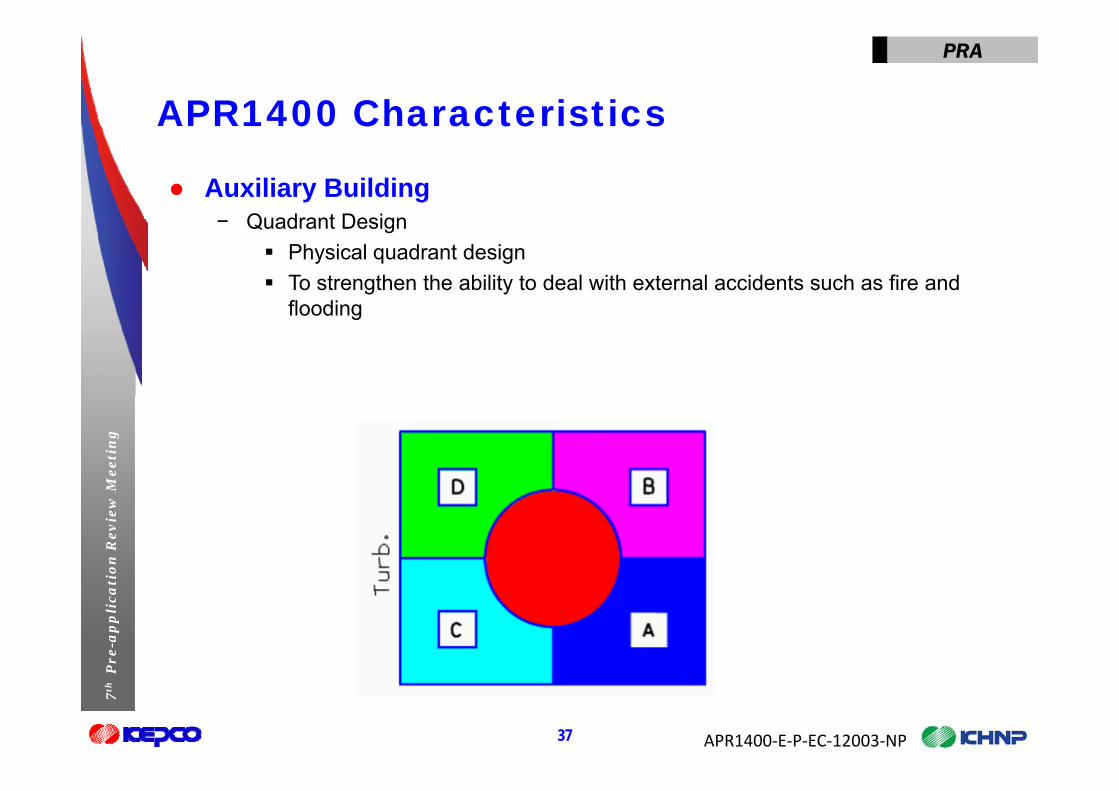
● Auxiliary Building Q d t D i− Quadrant Design Physical quadrant design To strengthen the ability to deal with external accidents such as fire and
floodingflooding
Mee
tin
gio
n R
evie
w M
Pre
-ap
pli
cati
APR1400‐E‐P‐EC‐12003‐NP
7th
P
37

PRA
APR1400 Characteristics00 C a acte st cs
● Auxiliary Building Arrangement− 1st floor− 1st floor
Four quadrants separated by watertight boundaries Pumps (SI/CCW/SC/CS/Charging PP)
− 2nd floor2nd floor HELB barriers for AFW Class 1E Breakers, AF pumps, Class 1E battery (C/D) Emergency Overflow Lines (EOLs) limit accumulation and direct water to
Mee
tin
g
g y ( )1st floor.
− 3rd floor EOLs limit accumulation and direct water to 1st floor via 2nd floor.
Cl N1E B k HVAC 2 EDG (C/D b fl ) Cl 1E b tt
ion
Rev
iew
M Class N1E Breakers, HVAC, 2 EDGs (C/D, base floor), Class 1E battery (A/B)
− 4th floor: MCCs, Spent Fuel pool area− 5th floor: RSP cable spreading room MG Set MS valves
Pre
-ap
pli
cati 5th floor: RSP, cable spreading room, MG Set, MS valves− 6th floor: MCR, I&C equipment room− 7th floor: HVAC− 8th floor: HVAC
APR1400‐E‐P‐EC‐12003‐NP
7th
P
38

PRA
APR1400 Characteristics00 C a acte st cs
● EDG Building (A/B) and Compound BuildingLi it d fl d− Limited flood sources
− Limited potential for propagation
● Turbine Building− Likely effect is loss of MFW. − Limited potential for propagation
Mee
tin
gio
n R
evie
w M
Pre
-ap
pli
cati
APR1400‐E‐P‐EC‐12003‐NP
7th
P
39
PRA
APR1400 Characteristics00 C a acte st cs
● Flood sources in Aux. Building are closed-loop.Li it d l− Limited volume
− Limited propagation
● Quadrant walls sealed for 9-foot flood elevation on 55-foot elevation.
● 10-inch EOL limits accumulation on upper elevations.● Ramps/Curbs limit propagation between quadrants on upper
Mee
tin
g
● Ramps/Curbs limit propagation between quadrants on upper elevations.
● Flooding alarms in the 1st floor of each quadrant provide rapid
ion
Rev
iew
M indication of flooding to main control room.
Pre
-ap
pli
cati
APR1400‐E‐P‐EC‐12003‐NP
7th
P
40

PRA
Flooding Insightsood g s g ts
● Segmentation of rooms limits spray damage.D i d t d t i h td− Damage in one quadrant does not require shutdown.
− Some electrical bus and distribution failures require TS shutdown.
● Good instrumentation to detect breaks− Most breaks do not require isolation.
● Beyond-design-basis fire protection breaks can propagate beyond barriers.
Mee
tin
g
beyond barriers.− Barriers assumed to fail if challenged.− Drainage through emergency overflow lines (EOLs) limits equipment damage
due to propagation.
ion
Rev
iew
M
due to p opagat o− Failures not expected to be risk significant.− Some failures of ECCS piping can challenge containment integrity.
Pre
-ap
pli
cati
APR1400‐E‐P‐EC‐12003‐NP
7th
P
41

Level 1 Fire Analysis
on
Mee
tin
gre
-ap
pli
cati
o7
thP
r

PRA
Fire PRAe
● GuidanceNUREG/CR 6850 (EPRI 1011989) Fi PRA− NUREG/CR-6850 (EPRI 1011989): Fire PRA
− ASME/ANS RA-Sa-2009 “PRA Standards”− NUREG-1921, “EPRI/NRC-RES Fire Human Reliability Analysis Guidlines“
NUREG/CR 6850 (EPRI 1019259) S l t 1− NUREG/CR-6850 (EPRI 1019259) Supplement 1
Mee
tin
gio
n R
evie
w M
Pre
-ap
pli
cati
APR1400‐E‐P‐EC‐12003‐NP
7th
P
43
PRA
APR1400 Characteristics00 C a acte st cs
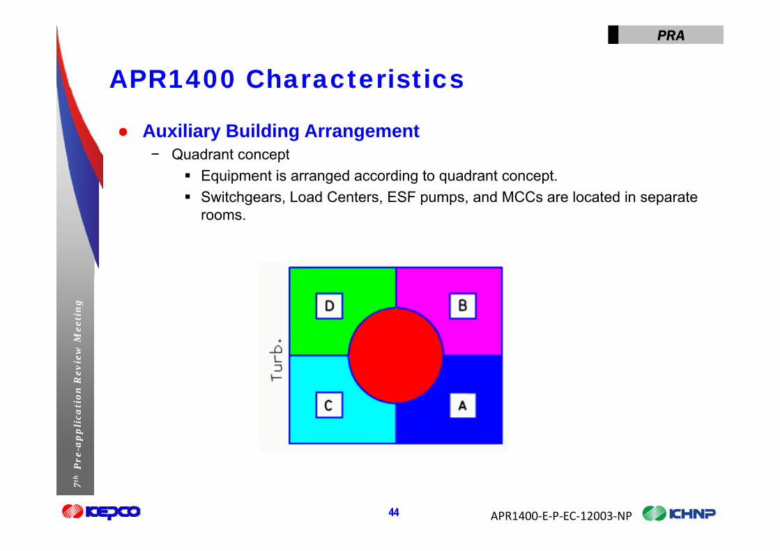
● Auxiliary Building ArrangementQ d t t− Quadrant concept Equipment is arranged according to quadrant concept. Switchgears, Load Centers, ESF pumps, and MCCs are located in separate
roomsrooms.
Mee
tin
gio
n R
evie
w M
Pre
-ap
pli
cati
APR1400‐E‐P‐EC‐12003‐NP
7th
P
44
PRA
APR1400 Characteristics00 C a acte st cs
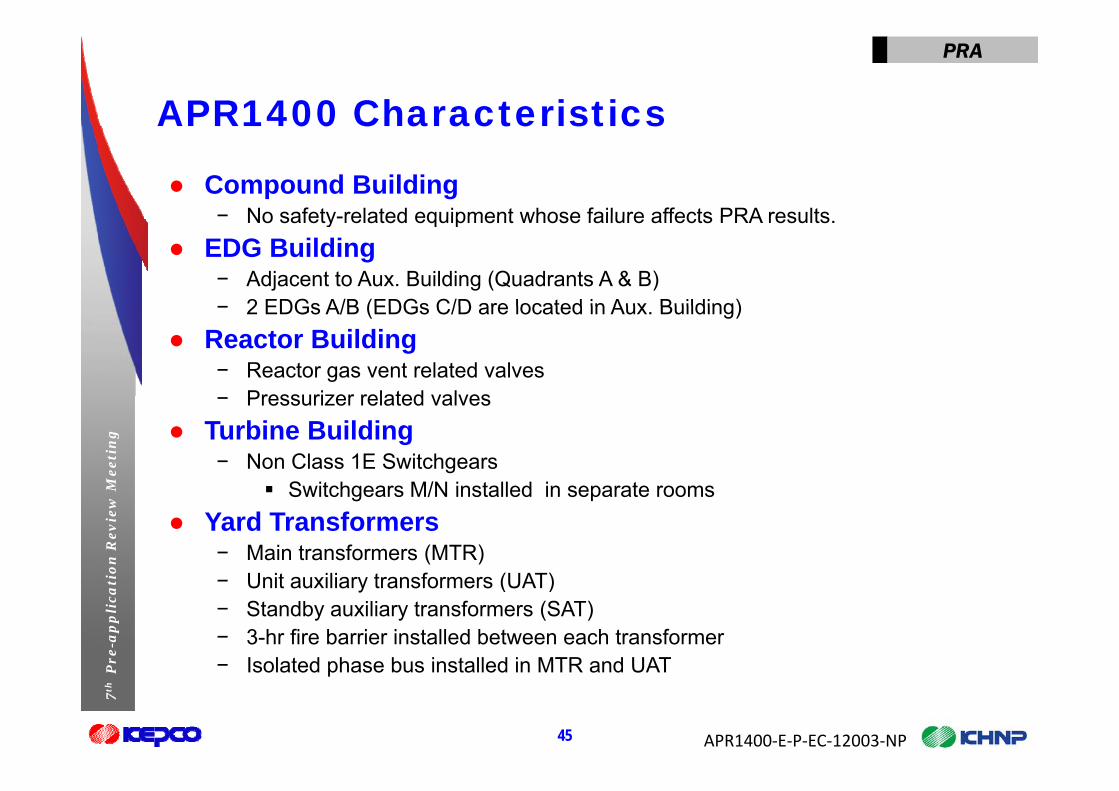
● Compound Building− No safety related equipment whose failure affects PRA results− No safety-related equipment whose failure affects PRA results.
● EDG Building− Adjacent to Aux. Building (Quadrants A & B)− 2 EDGs A/B (EDGs C/D are located in Aux Building)− 2 EDGs A/B (EDGs C/D are located in Aux. Building)
● Reactor Building− Reactor gas vent related valves
Pressurizer related valves
Mee
tin
g
− Pressurizer related valves● Turbine Building
− Non Class 1E SwitchgearsS it h M/N i t ll d i t
ion
Rev
iew
M Switchgears M/N installed in separate rooms● Yard Transformers
− Main transformers (MTR)U it ili t f (UAT)
Pre
-ap
pli
cati − Unit auxiliary transformers (UAT)− Standby auxiliary transformers (SAT)− 3-hr fire barrier installed between each transformer− Isolated phase bus installed in MTR and UAT
APR1400‐E‐P‐EC‐12003‐NP
7th
P
45
− Isolated phase bus installed in MTR and UAT

PRA
APR1400 Characteristics00 C a acte st cs
● 3-hr rated fire barrier in all fire areas2 h fi b i f t i− 2-hr fire barriers for stairs
● Main Control Room− Large Display Panel, five Operator Consoles, and
Safety Console− Safety Console is a backup− Independent HVAC system
Mee
tin
g
● Remote Shutdown Room− Remote Shutdown Panel
ion
Rev
iew
MP
re-a
pp
lica
ti
APR1400‐E‐P‐EC‐12003‐NP
7th
P
46

PRA
APR1400 Characteristics00 C a acte st cs
● All cables are IEEE-383 qualified C C● Control Cabinets are locally distributed.− Group Control Cabinets are located in I&C equipment rooms near MCR.− Component Control Cabinets are located near each local room (quadrant
design).
● Automatic Suppression System in Aux. Building− CO2 Suppression system in switchgear/EDG rooms
Mee
tin
g
2 pp y g− Water sprinkler system in corridors of each floor
ion
Rev
iew
MP
re-a
pp
lica
ti
APR1400‐E‐P‐EC‐12003‐NP
7th
P
47

PRA
Fire Insightse s g ts
● The APR1400 has two divisions each consisting of two trains of safety systems Each division is segregated with physical firesafety systems. Each division is segregated with physical fire barriers so as to protect the safety function of safety systems from fires impacting the opposite division. Any fire impacting both divisions requires failure of a 3 hour fire barrier.q
● The APR1400 Auxiliary Building is divided into four quadrants, two quadrants per division each quadrant is segregated with physical fire barriers. Each quadrant contains the equipment for a
Mee
tin
g
safety train.● The APR1400 has a highly compartmentalized Auxiliary Building
comprised of many fire areas with 3 hour fire rating barriers so as
ion
Rev
iew
M to minimize the impact from any single fire in the Auxiliary Building.
● The APR1400 employs fiber optic cables between the Main C t l R th t ll d l t ll th b
Pre
-ap
pli
cati Control Room, the group controllers and loop controllers thereby minimizing the impact from fire induced spurious hot shorts.
● Fire model consideration of the highly integrated control room (HICR) ill b f d i lit ti l i
APR1400‐E‐P‐EC‐12003‐NP
7th
P
48
(HICR) will be performed using qualitative analysis.

Level 1 Seismic Assessment
on
Mee
tin
gre
-ap
pli
cati
o7
thP
r

PRA
Methodologyet odo ogy
● DC/COL-ISG-020, Interim Staff Guidance on Implementation of a PRA Based Seismic Margin Analysis for New Reactorsa PRA-Based Seismic Margin Analysis for New Reactors− PRA-based SMA for advanced nuclear power plants
Conservative Deterministic Failure Margin (CDFM) Approach for Estimation of Structure and component HCLPFof Structure and component HCLPF
− The lowest core damage sequence HCLPF (High Confidence Low Probability of Failure) value should have at least 1.67 times the CSDRS (Certified Seismic Design Response Spectrum)
Mee
tin
g
Design Response Spectrum) HCLPF > 0.5g
● Analysis StepsS l t S i i E i t Li t
ion
Rev
iew
M − Select Seismic Equipment List− Derive HCLPF values for components and structures (CDFM)− Develop Seismic Initiating Event Trees and Fault Tree Models
S l th S i i E t T
Pre
-ap
pli
cati − Solve the Seismic Event Trees− Calculate HCLPF values for the seismic core damage sequences− Determine the plant HCLPF
APR1400‐E‐P‐EC‐12003‐NP
7th
P
50

Level 2 Analysis
on
Mee
tin
gre
-ap
pli
cati
o7
thP
r

PRA
Level 2 PRA Methodologye e et odo ogy
● Level 2 PRA Methodology NUREG/CR 2300 PRA P d G id− NUREG/CR-2300 : PRA Procedures Guide
− NUREG-1150 : Severe Accident Risks− NUREG-1335 : IPE Submittal Guidance
CESSAR DC S t 80 PRA− CESSAR DC : System 80+ PRA− ASME/ANS RA-Sa-2009 “PRA Standards”
● Containment Event Tree and Decomposition Event Tree
Mee
tin
g
(CET/DET) methodology is used.● Computer Codes
− MAAP 4 0 8 for analyzing severe accident progression and source term release
ion
Rev
iew
M MAAP 4.0.8 for analyzing severe accident progression and source term release− SAREX 1.2 for developing Level 2 PRA model
Pre
-ap
pli
cati
APR1400‐E‐P‐EC‐12003‐NP
7th
P
52

PRA
Level 2 PRA Processe e ocessM
eeti
ng
ion
Rev
iew
MP
re-a
pp
lica
ti
APR1400‐E‐P‐EC‐12003‐NP
7th
P
53

PRA
Design Features against Severe Accidents g g
● Containment Building− Pre-stressed concrete containment with a steel liner plate, Large Dry Containment p , g y
● Reactor Cavity Design− Convoluted Flow Path to decrease the amount of ejected core debris− Large cavity floor area (greater than 0.02 m2/MWt)
Th t thi k 3 f t− The concrete thickness are 3 feet● Cavity Flooding System (CFS)
− Minimize or eliminate corium-concrete attack due to MCCI● Hydrogen Mitigation System (HMS)
Mee
tin
g
● Hydrogen Mitigation System (HMS)− Limit hydrogen concentration in containment, generated from a 100-percent fuel
clad-coolant reaction less than 10 v/o− 30 PARs and 8 Igniters
● Safety Depressurization and Vent System (SDVS)
ion
Rev
iew
M ● Safety Depressurization and Vent System (SDVS)− Provide a means to rapidly depressurize the primary system to about 250psia to
prevent DCH following severe accidents● ECSBS (Emergency Containment Spray Backup System)
Pre
-ap
pli
cati
( g y p y p y )− An alternate mean of providing containment spray water after 24 hours following
severe accidents− Deliver water from external water source to the ECSBS containment spray header− Use pumping device (i.e., fire engine truck) independent of normal and emergency
APR1400‐E‐P‐EC‐12003‐NP
7th
P
54
p p g ( , g ) p g yAC power sources.

PRA
Plant Damage Statea t a age State
● Plant Damage States (PDSs)− Collections of accident sequence end states according to plant conditions at the onsetCollections of accident sequence end states according to plant conditions at the onset
of severe core damage− Represent the interface between the Level 1 and Level 2 analyses
● Level 1 event trees− Extended as necessary to assess the availability of all systems important to the
containment accident progression analysis. Containment isolation system, cavity flooding system, hydrogen mitigation
system, containment spray system and so on.
Mee
tin
g
system, containment spray system and so on.− Grouped by PDS grouping parameters
● PDS grouping parameters − Containment Bypass
ion
Rev
iew
M
yp− Containment Isolation− LOCA or Transients− RCS Pressure at the time of core damage
R t C it C diti
Pre
-ap
pli
cati − Reactor Cavity Condition− In-vessel Injection− Release Points of RCS Inventory− Containment Heat Removal
APR1400‐E‐P‐EC‐12003‐NP
7th
P
55
Containment Heat Removal− Feedwater Injection into SGs

PRA
Plant Damage State Event Treea t a age State e t ee
● PDS Event Tree (Example)
Mee
tin
g Additional Headings for PDS ETs
ion
Rev
iew
MP
re-a
pp
lica
ti
APR1400‐E‐P‐EC‐12003‐NP
7th
P
56

PRA
Containment Structural CapabilitiesCo ta e t St uctu a Capab t es
● Considered Containment Failure Locations by Quasi-Static PressurePressure− Failure due to membrane stresses (including hoop and meridional failure in the
cylindrical wall and dome)Radial shear failure of the cylindrical wall at the base− Radial shear failure of the cylindrical wall at the base
− Flexural failure of the cylindrical wall at the base− Shear failure of the base slab/Flexural failure of the base slab
F il f E i t H t h A bl /P l A Ai l k A bl
Mee
tin
g
− Failure of Equipment Hatch Assembly/Personnel Access Airlock Assembly − Failure of Personnel Emergency Exit Assembly/Fuel Transfer Tube− Failure at Pipe Penetrations/Electrical Penetrations/Bellows
Li B kli /Th l b kli f li l
ion
Rev
iew
M − Liner Buckling/Thermal buckling of liner plate
● The two containment failure modes are determined based on
Pre
-ap
pli
cati NUREG-1150 and NUREG/CR-6906− Rupture : The containment fails with break size of greater than 1.0 ft2
− Leak : The containment fails with break size of 0.1 ft2
APR1400‐E‐P‐EC‐12003‐NP
7th
P
57

PRA
Containment Failure ModesCo ta e t a u e odes
● NUREG-1335 and NUREG-1150 provide the several containment challenges and the severe accident riskscontainment challenges and the severe accident risks.
● The following potential containment challenges are assessed in Level 2 analysis − Direct Bypass (SGTR and ISLOCA)− Steam Explosions (In-vessel/Ex-vessel) − Hydrogen Combustion Processes (Slow Combustion/Detonation)
Mee
tin
g
y g ( )− Steam Over-pressurization − Molten Core-Concrete Interaction (Basemat Melt-through) − Blowdown Forces (Vessel Thrust Force or Rocket Mode Failure)
ion
Rev
iew
M
( )− Liner Melt-Through (Direct Contact of Containment Shell with Fuel Debris) − Failure of Containment Building Penetrations
Pre
-ap
pli
cati
APR1400‐E‐P‐EC‐12003‐NP
7th
P
58
PRA
Containment Event TreeCo ta e t e t ee
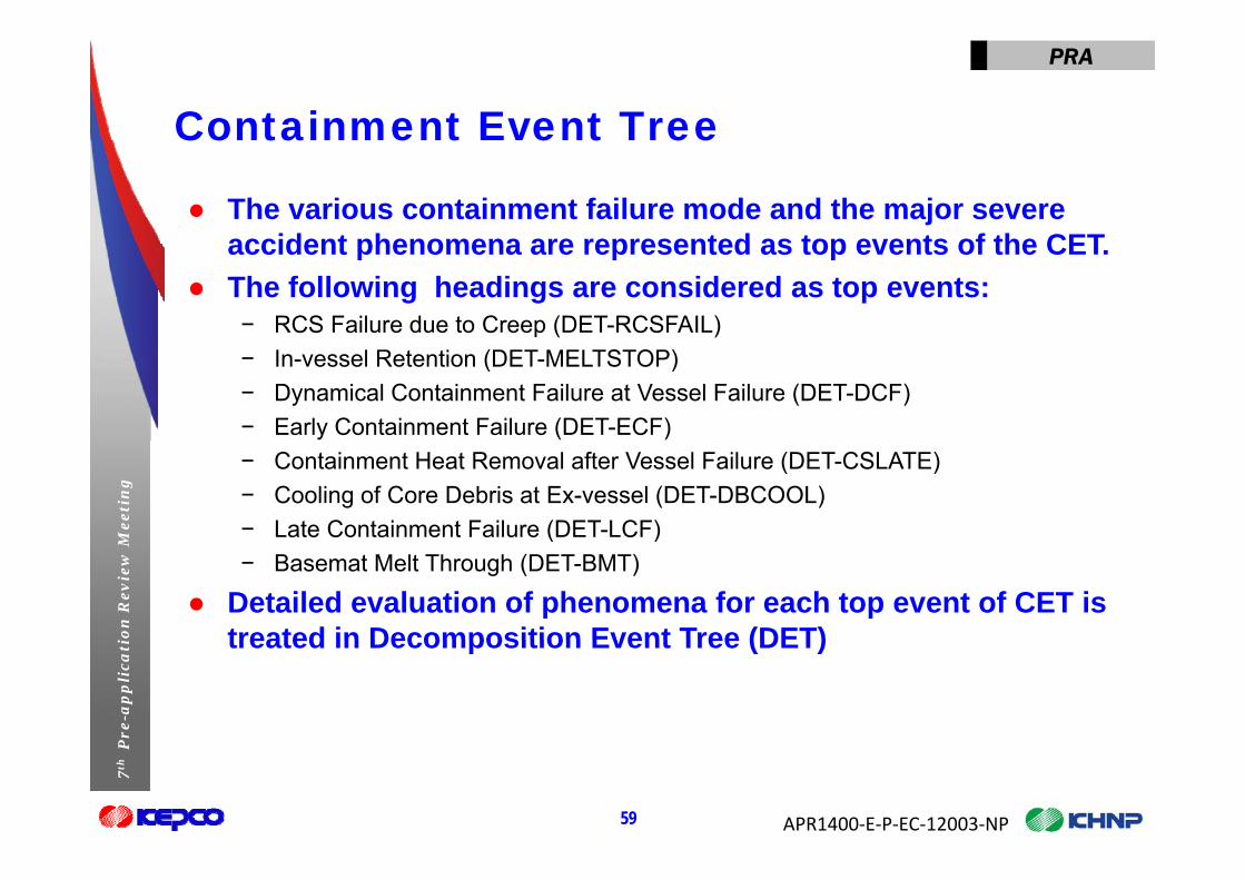
● The various containment failure mode and the major severe accident phenomena are represented as top events of the CETaccident phenomena are represented as top events of the CET.
● The following headings are considered as top events:− RCS Failure due to Creep (DET-RCSFAIL)− In-vessel Retention (DET-MELTSTOP)− Dynamical Containment Failure at Vessel Failure (DET-DCF)− Early Containment Failure (DET-ECF)
Mee
tin
g
− Containment Heat Removal after Vessel Failure (DET-CSLATE)− Cooling of Core Debris at Ex-vessel (DET-DBCOOL)− Late Containment Failure (DET-LCF)
ion
Rev
iew
M
( )− Basemat Melt Through (DET-BMT)
● Detailed evaluation of phenomena for each top event of CET is treated in Decomposition Event Tree (DET)
Pre
-ap
pli
cati treated in Decomposition Event Tree (DET)
APR1400‐E‐P‐EC‐12003‐NP
7th
P
59
PRA
Containment Event TreeCo ta e t e t ee
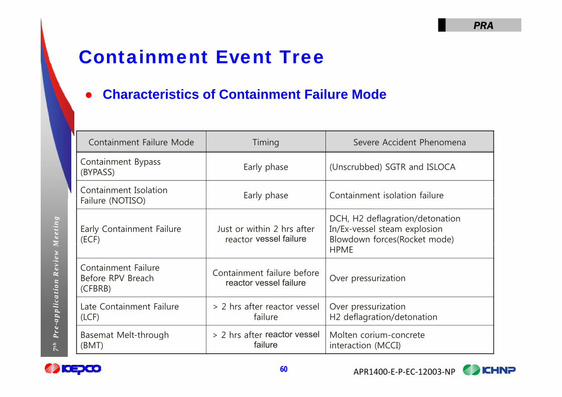
● Characteristics of Containment Failure Mode
Containment Failure Mode Timing Severe Accident Phenomena
Containment Bypass (BYPASS)
Early phase (Unscrubbed) SGTR and ISLOCA
Containment IsolationF il (NOTISO)
Early phase Containment isolation failure
Mee
tin
g
Failure (NOTISO) y p
Early Containment Failure(ECF)
Just or within 2 hrs after reactor vessel failure
DCH, H2 deflagration/detonationIn/Ex-vessel steam explosion Blowdown forces(Rocket mode)
ion
Rev
iew
M
( ) ( )HPME
Containment Failure Before RPV Breach (CFBRB)
Containment failure before reactor vessel failure Over pressurization
Pre
-ap
pli
cati (CFBRB)
Late Containment Failure(LCF)
> 2 hrs after reactor vessel failure
Over pressurizationH2 deflagration/detonation
Basemat Melt through > 2 hrs after reactor vessel Molten corium concrete
APR1400‐E‐P‐EC‐12003‐NP
7th
P
60
Basemat Melt-through (BMT)
> 2 hrs after reactor vessel failure
Molten corium-concreteinteraction (MCCI)
PRA
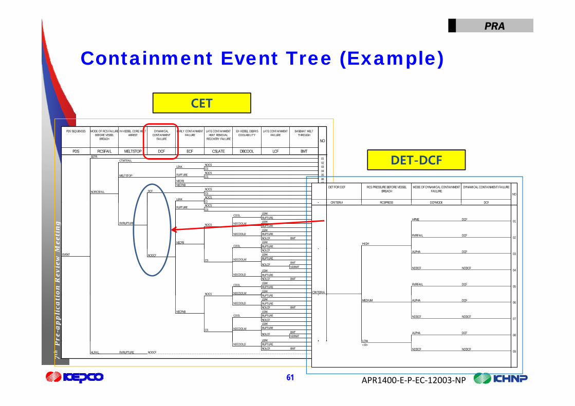
Containment Event Tree (Example)Co ta e t e t ee ( a p e)
CET
SGTR
PDS RCSFAIL MELTSTOP DCF ECF CSLATE DBCOOL LCF BMT
PDS SEQUENCES MODE OF RCS FAILUREBEFORE VESSEL
BREACH
IN-VESSEL CORE MELTARREST
DYNAMICALCONTAINMENT
FAILURE
EARLY CONTAINMENTFAILURE
LATE CONTAINMENTHEAT REMOVAL
RECOVERY FAILURE
EX-VESSEL DEBRISCOOLABILITY
LATE CONTAINMENTFAILURE
BASEMAT MELTTHROUGH
NO
DET DCFSGTRCTMTFAIL
NOCSCS
LEAK
NOCSCS
RUPTURE
NECFBNECFNB
MELTSTOP
NOCSCS
DCF
NOCSCS
LEAK
NORCSFAIL
010203040506070809101112 CRITERIA RCSPRESS DCFMODE DCF
DET FOR DCF RCS PRESSURE BEFORE VESSELBREACH
MODE OF DYNAMICAL CONTAINMENTFAILURE
DYNAMICAL CONTAINMENT FAILURE
NO
DET-DCF
Mee
tin
g
NOCSCS
RUPTURE
LEAKRUPTURE
COOL
LEAKRUPTURE
NOCOOLW
LEAKRUPTURE
BMTNOLCFNOCOOLD
NOCS
LEAKRUPTURENOLCF
COOLNECFB
RVRUPTURE
121314151617181920212223
DCFHPME
DCFRVRFAIL
HIGH
CRITERIA RCSPRESS DCFMODE DCF
01
02
ion
Rev
iew
M NOLCFLEAKRUPTURE
BMTNOBMT
NOLCF
NOCOOLW
LEAKRUPTURE
BMTNOLCFNOCOOLD
CS
LEAKRUPTURE
COOL
LEAKRUPTURE
NOCOOLWNOCS
NODCFEVENT
232425262728293031323334
DCFALPHA
NODCFNODCF
DCFRVRFAIL
CRITERIA
03
04
05
Pre
-ap
pli
cati RUPTURE
LEAKRUPTURE
BMTNOLCFNOCOOLD
LEAKRUPTURENOLCF
COOL
LEAKRUPTURE
BMTNOBMT
NOLCF
NOCOOLW
LEAK
CS
NECFNB
353637383940414243444546
DCFALPHA
NODCFNODCF
MEDIUM
DCFALPHA
LOW
06
07
08
APR1400‐E‐P‐EC‐12003‐NP
7th
P
61
LEAKRUPTURE
BMTNOLCFNOCOOLD
NODCFRVRUPTUREHLFAIL
464748 NODCFNODCF
LOW<R>
09

PRA
Source Term Category Sou ce e Catego y
● The end points of CETs represent the possible accident sequences that describes complete accident scenarios fromsequences that describes complete accident scenarios from initiating events to release into environment.− In general, a detailed source term analysis for all end points is very difficult and
t b t f iblseems to be not feasible.
● It is necessary to group the CET accident sequences that have similar release characteristics into a corresponding release
Mee
tin
g
category (or Source Term Category). ● Source term release analysis is performed
− For a representative sequence of each STC which is determined based on
ion
Rev
iew
M For a representative sequence of each STC, which is determined based on frequency (or contribution to its STC) and amount of source term released to the environment
− Using MAAP 4.0.8 code
Pre
-ap
pli
cati
g
APR1400‐E‐P‐EC‐12003‐NP
7th
P
62

PRA
Level 2 Results Analysise e esu ts a ys s
● The Level 2 Results AnalysisR i f i ifi t− Review of significant sequences
− Identification of Significant contributors to risk To determine if additional recovery actions or equipment redundancy would
significantly reduce the risksignificantly reduce the risk. − Relevant sensitivity analysis− Characterization of sources of uncertainty
Mee
tin
gio
n R
evie
w M
Pre
-ap
pli
cati
APR1400‐E‐P‐EC‐12003‐NP
7th
P
63

Low Power and Shutdown Analysis
on
Mee
tin
gre
-ap
pli
cati
o7
thP
r

PRA
Introductiont oduct o
● Scope I t l E t d E t l E t (I t l Fi /Fl di )− Internal Events and External Events (Internal Fire/Flooding)
● Assumptions− Based on typical Korean nuclear power plant outage experiences and
procedures, with modification to consider APR1400 design characteristics
● Methodology− CESSAR PRA for LPSD operation
Mee
tin
g
p− NUREG/CR-6144− PRAs of Korean Standard Nuclear Power Plants PRA with experience from
LPSD operation
ion
Rev
iew
MP
re-a
pp
lica
ti
APR1400‐E‐P‐EC‐12003‐NP
7th
P
65

PRA
Methodology -Analysis Stepet odo ogy a ys s Step
● Internal EventsPl t O ti l St t A l i− Plant Operational State Analysis
− Initiating Events Analysis− Accident Sequence Analysis
S C it i− Success Criteria− Systems Analysis− Human Reliability and Data Analysis
Mee
tin
g
− Quantification
● External Events
ion
Rev
iew
MP
re-a
pp
lica
ti
APR1400‐E‐P‐EC‐12003‐NP
7th
P
66

PRA
Methodology– Design Features and gy gMitigating Functions ● Design Features for LPSD
I t t ti t it d d i t ti− Instrumentation to monitor reduced inventory operation− Procedure to prevent overpressure of RCS during loss of RHR− Design change to mitigate Shutdown Cooling pump cavitation caused by
entrainment of air in the pump suctionentrainment of air in the pump suction
● Mitigating functions during LPSD can be categorized into two groups
Mee
tin
g
− Decay heat removal function RHR using Shutdown Cooling System SG if RHR is unavailable
ion
Rev
iew
M − RCS inventory make-up function Safety injection system Chemical and Volume Control System
Pre
-ap
pli
cati – To prevent bulk boiling and maintain the RCS water level
APR1400‐E‐P‐EC‐12003‐NP
7th
P
67

PRA
Methodology– Definition of POSet odo ogy e t o o OS
● The outage is divided into 17 POSs based on RCS conditions and system configurationsand system configurationsPOS T/S mode Description
1 1,2 Reactor trip and subcritical state
2 3 Hot standby
3 4 5 Hot and cold shutdown (RCS intact)3 4, 5 Hot and cold shutdown (RCS intact)
4A 5 Cold shutdown (Draining RCS) (RCS not intact, RCS vent)
4B 5 Cold shutdown (Draining RCS) (RCS not intact, Pressurizer manhole)
Mee
tin
g
5 5 Cold shutdown (Reduced inventory) (RCS not intact)
6 5 Cold shutdown (Filling RCS) (RCS not intact)
7~9 6 Refueling
ion
Rev
iew
M
10 5 Cold shutdown (Filling RCS) (RCS not intact)
11 5 Cold shutdown (Reduced inventory) (RCS not intact)
12A 5 C ld h td (Filli RCS) (RCS t i t t P i h l )
Pre
-ap
pli
cati 12A 5 Cold shutdown (Filling RCS) (RCS not intact, Pressurizer manhole)
12B 5 Cold shutdown (Filling RCS) (RCS not intact, RCS vent)
13 4 Hot and cold shutdown (RCS intact)
APR1400‐E‐P‐EC‐12003‐NP
7th
P
68
14 3 Hot standby
15 1,2 Reactor Startup

PRA
Methodology– Initiating Eventset odo ogy t at g e ts
● Initiating Events for LPSD PSA are listed belowLOCA− LOCA Large, Medium and Small LOCA, SGTR, Main Steam Line Break during Hot
Standby Unrecoverable LOCA occurred by operator error Unrecoverable LOCA occurred by operator error
− Loss of RHR due to over-drain During transition from the normal condition to reduced inventory operation
L f RHR d b f ili t i t i t l l
Mee
tin
g
− Loss of RHR caused by failing to maintain water level During reduced inventory operation
− Loss of RHR caused by other failuresR bl U bl l f RHR
ion
Rev
iew
M Recoverable or Unrecoverable loss of RHR− Loss of CCW/ESW− Loss of offsite power and SBO
Pre
-ap
pli
cati − Loss of 4.16kV Switchgear Bus
● The frequency of Initiating Events− NUREG/CR-6144, the latest industry data, and design features for RHR
APR1400‐E‐P‐EC‐12003‐NP
7th
P
69
operation
PRA
Methodology– Accident Sequence et odo ogy cc de t Seque ce
● The Accident Sequence DevelopmentE t T d l t− Event Tree development For all initiating events and POSs
− Procedures and experience of OPR1000O t d hift i ’ l b k d Operator procedures, shift supervisor’s log book, and so on
− Success criteria based on thermal hydraulic analysis According to IMC-0609 App G (Inspection manual) of NRC, success criteria
f d f LPSD i 1 300F f P k C T t
Mee
tin
g
of core damage for LPSD is 1,300F of Peak Core Temperature RELAP5 Mod 3 for RCS conditions of each POS MAAP4.0.8 for Containment Heat Removal
D i f t f RHR ti
ion
Rev
iew
M − Design features for RHR operation To meet GL 88-17 requirements during LPSD Operation To prevent RHR operation from loss of shutdown cooling and loss of reactor
coolant
Pre
-ap
pli
cati coolant
APR1400‐E‐P‐EC‐12003‐NP
7th
P
70

PRA
Methodology– Event Tree Analysis et odo ogy e t ee a ys s
● Loss of RHR (Example)D t d i d f il t i t i RCS t d i d d i t
Loss of RHR d e to o e d ain In ento Make p Sta t Stand b SCS Feed
− Due to overdrain and failure to maintain RCS water during reduced inventory operation
SOIE MK RS FD
Loss of RHR due to overdrainand failure to maintain RCS
water
Inventory Makeup Start Stand-by SCS Feed
NOPDS
Mee
tin
g
01 OK
02 OK
ion
Rev
iew
M
03 CD
04 OK
Pre
-ap
pli
cati 04 OK
05 CD Event Description SOIE : initiating event (Loss of RHR)
APR1400‐E‐P‐EC‐12003‐NP
7th
P
71
MK : RCS inventory makeup RS : Start stand-by SCS FD : Injection water to RCS by using SI and SCS pump
PRA
Methodology– Human ReliabilityMethodology Human Reliability● Human Reliability Analysis
LPSD PSA th HRA th d l t th t f f ll L l 1− LPSD PSA uses the same HRA methodology to that of full power Level 1 internal events PRA
Mee
tin
gio
n R
evie
w M
Pre
-ap
pli
cati
APR1400‐E‐P‐EC‐12003‐NP
7th
P
72

Closing Remarks
- Use of PRA to Support DesignUse of PRA to Support Design
- Summary
on
Mee
tin
gre
-ap
pli
cati
o7
thP
r

PRA
Use of PRA To Support DesignUse o o Suppo t es g
● Design Changes from Shin-Kori 3&44 EDG f 2 EDG− 4 EDGs from 2 EDGs Significant impact on SBO sequences
− Capacity of Class 1E batteries C/D16 h f 8 h ith l h ddi 16 hours from 8 hours with manual shedding
Moderate impact on SBO sequences− RTSS (Reactor Trip Switchgear System)
Mee
tin
g
Full 2/4 (8 RTBs) from selective 2/4 (4 RTBs) Limited impact on CDF
ion
Rev
iew
MP
re-a
pp
lica
ti
APR1400‐E‐P‐EC‐12003‐NP
7th
P
74

PRA
SummarySu a y
● The preliminary CDF from internal events for full power is at low 10-6 per reactor yearlow 10-6 per reactor year.
● The preliminary results from external events indicate that the quadrant/divisional design is highly effective in risk reduction.
● Level 2 and LPSD assessments are still in preliminary stage.● Peer Reviews
I t l E t PRA (i l di i t l fl d)
Mee
tin
g
− Internal Events PRA (including internal flood)
ion
Rev
iew
MP
re-a
pp
lica
ti
APR1400‐E‐P‐EC‐12003‐NP
7th
P
75