Embed Size (px)
Citation preview

ProAcquire PSP-CCD-C/M Cameras Operation Manual (version 3.3)

Innovative Scientific Solutions, Inc.
Table of Contents
Specifications ..........................................................................................................2
Software Installation ...............................................................................................4
Maximizing Performance ........................................................................................8
NIC Network Setup ..................................................................................................8
Software Interface ...................................................................................................11
Camera Operating Modes .......................................................................................19
Radiometric Mode ...................................................................................................19
Double Framing Mode .............................................................................................21
Frame Accumulation Mode .....................................................................................22
Multi Camera Mode .................................................................................................24
Network Configuration for Multi-Camera Mode ......................................................26
Export Disclaimer ....................................................................................................34
Software License and Limited Warranty ..................................................................35
For questions or comments, please contact ISSI Innovative Scientific Solutions, Incorporated 7610 McEwen Road Dayton, OH 45459 Ph.: (937) 630-3012 Fax: (937) 630-3015 Email: [email protected] www.psp-tsp.com
Revision Date: 8/7/2017
1

Innovative Scientific Solutions, Inc.
Specifications
Sensor Resolution 1600 x 1200 (active) Type KAI-2020 CCD
Format 11.89 mm (H) x 8.94 mm (V), 14.8 mm diagonal (1” optical format)
Pixel Size 7.4 µm
Frame Rate 35 fps (40 MHz) Standard clock 44 fps (50 MHz) Overclocked
Electron Full Well Capacity 40,000 e− Readout Noise 20 electrons Dynamic Range 60dB Output Format(s) 8, 12, 14-bit (single AD only) Binning H/L 1x, 2x, 3x, 4x, 8x Interframe Transfer Time 200 ns Maximum Exposure 16 seconds Trigger Inputs External (TTL via IN1/IN2), software, computer Options Level, edge, pulse width, internal exposure Modes Free-run, standard, double, frame accumulation Strobe Output Programmable position and duration Communication Interface GigE On Board Memory None Software Interface ProAcquire Lens Control Available in ProAcquire (LC-2 integration) Environmental Vibration/Shock 100g Operating Temperature Range -40˚C to 85˚C Humidity 10% to 90% non-condensing Size & Weight Size 46 mm (L) x 46 mm (H), 68.6 mm (L) Operating Temperature Range -40˚C to 85˚C Humidity 10% to 90% non-condensing Weigth 219 grams Lens Mount c-mount Power Requirements External Power Input 12V 2A Power Consumption 4.8 W Export ECCN EAR99
2

Innovative Scientific Solutions, Inc.
The PSP-CCD is a 2-megapixel CCD camera. The camera is small and lightweight at
210g allowing for an array of cameras to be mounted in a tight place for larger scale viewing
and applications. The camera comes in two styles, one with a color chip and one with a
monochrome chip. The color camera is used in applications where spectral separation of incoming light is needed such as Binary PSP and particle shadow velocimetry applications.
The monochrome version is used in applications where spectral separation of the incoming
light is not needed, for example; single luminophore PSP or S3F applications.
Use of the PSP-CCD-C allows binary pressure sensitive paint data (two separate
spectral peaks) to be acquired using a single camera. Rather than use optical filters in front of
the camera lens, the filtering is applied on the chip using a standard Bayer filter. In the case of
Binary FIB, the signal channel is acquired on the red pixels and the reference channel is
acquired on the green pixels. All images are acquired through a single camera and lens and
this process minimizes image alignment errors. This single chip system also accomplishes a
second goal, all data is acquired simultaneously, and thus the stability of the illumination
source is a less significant issue. The major drawback of this approach is the loss of spatial resolution. In a color chip, only ¼ of the pixels are sensitive to the signal channel (red pixels)
on the standard Bayer filter. Despite the loss of spatial resolution, the color camera approach
produces excellent results at low speeds.
Quantum Efficiency of Color Sensor Quantum Efficiency of Monochrome Sensor
Spectral plot of IR Blocking filter in the camera
3

Innovative Scientific Solutions, Inc.
Software Installation
The PSP-CCD operates with ProAcquire GigE. The software is compiled for 32- and 64-bit Window operating systems XP, Vista and 7. Locate the appropriate installation file to begin installation.
The setup page will open and prompt the user to continue with the installation.
The setup will next open and display the license agreement for the software.
4

Innovative Scientific Solutions, Inc.
Navigate to the destination where the software will be stored on the computer and proceed with the installation.
5

Innovative Scientific Solutions, Inc.
If this is the first time to install ProAcquire, then the drivers will need to be installed to the NIC. If this is an upgrade to an existing version of ProAcquire, the drivers will not need updating, only the software. The installer will ask which option for installation.
If a full install is selected, the program will proceed to install the drivers. The eBUS driver installation tool will open and give the option to install the eBUS driver. The driver will be installed on the network interface card on the computer. If the eBUS driver is already installed (as pictured below) select the action ‘Do Nothing’ and close the window. If it is not yet installed, the ‘Current Driver’ will be the ‘Manufacturer Driver’ and the ‘Install eBUS Driver’ should be chosen for action.
6

Innovative Scientific Solutions, Inc.
Driver not installed above. Installed below.
Once installation is complete, reboot the computer.
7

Innovative Scientific Solutions, Inc.
Maximizing Performance To get the fastest performance from the camera, use a Cat6 Ethernet cable (supplied) and a computer with a Gigabit Ethernet Network Interface Card (NIC). Gigabit Ethernet has a maximum data transfer rate of 1 gigabit per second while fast Ethernet (FE) is limited to 100 megabits per second. Using a computer with a GigE NIC will enable the camera to collect data at its maximum frame rate of 35/44 (normal/overclocked) frames per second. All other Gigabit Ethernet devices should be disconnected from the computer and disabled from the network while using the PSP-CCD. To increase the frame rate capability on the computer and use the full bandwidth of the NIC, Jumbo frames should be enabled and the value should be set to the maximum for the computer. The maximum values are either 7KB or 9KB MTU. Once the computer has been properly configured for the camera, open the software from the desktop icon to display the GUI. To enable the maximum for jumbo frames, navigate from the Control Panel.
Control Panel > Network and Internet > Network and Sharing Center > Change Adapter Settings > LAN (Right-Click) > Properties > Configure > Advanced > Under ‘Properties’, select ‘Jumbo Frame’ and set value to maximum.
NIC Network Setup The network on the PC NIC (network interface card) needs to be properly configured for communication over the network. To do this, navigate to the ‘Network Connections’ page on the control panel where the local networks of the computer is displayed. Right-click on the network where the PSP-CCD is connected and select ‘Properties.’
8

Innovative Scientific Solutions, Inc.
From the ‘Local Area Connection X Properties’ window, click on ‘Internet Protocol Version 4 (TCP/IPv4)’ and then press the ‘Properties’ button, now useable. This will open the ‘Internet Protocol Version 4 (TCP/IPv4) Properties’ window. This is where the IP addresses are entered so that PSP-CCD can be reached over the local network. The settings needed for communication are IP Address and Subnet mask.
The IP address of the NIC should use the following conventions:
IP Format: Network.Network.Subnet.Host
• PSP-CCD IP: 192.168.2.252 • NIC IP: 192.168.2.XXX
The NIC IP address should have the same network and subnet addresses but a unique host, the last line of the IP address. The host can be any value 1-254 but different from the host address of the PSP-CCD. The subnet mask should be set to match that of the PSP-CCD which, by default is 255.255.255.0. The Default Gateway and all other fields can be left blank.
9

Innovative Scientific Solutions, Inc.
Additional subnetworks can be configured for the same NIC. In the ‘Internet Protocol Version 4 (TCP/IPv4)’ window, the Advanced button will open the ‘Advanced TCP/IP Settings’ window. IP addresses of any subnetwork can be added for that NIC here. If multiple devices are being used on the same network and they have differing subnetworks, this option provides communication for all devices without the need to change IP addresses for each device.
If connection problems persist, check the connection of the Ethernet cable between the computer NIC and the camera. To check that there is a physical connection, ping the IP address of the camera from the Command Prompt. To do this, open the command prompt window and enter:
Ping XXX.XXX.XXX.XXX –t
10

Innovative Scientific Solutions, Inc.
Software Interface ProAcquire is the software package used with the PSP-CCD. There are three acquisition capabilities of the camera and each has its own control interface within ProAcquire. ProAcquire is made to be a simple and effective interface for the user that is directly compatible in output file format with ISSI post processing software.
Opening the software will open the main page of the software. At this point, the software will be inactive since no camera has been selected.
To connect to a camera, press the ‘Open’ button:
This will show all connected cameras with their IP addresses and serial numbers.
A camera highlighted in yellow is busy and connected to another computer running ProAcquire. If a camera is displayed in grey, its IP address does not match the local network and should be changed to match the local network. To do this, click on the camera in grey
11

Innovative Scientific Solutions, Inc.
and press Change IP. Once the IP address matches the local network, the text will change to black. Double-click on the camera to open.
Once the camera is connected, all of the features of the software will be active.
Once the features have been activated, the buttons will show color meaning the camera is connected.
The toolbar controls the camera acquisition parameters.
Preview will display a preview of the camera view. This can be externally triggered and will operate at the maximum repetition rate possible based on the sensor and exposure settings.
Capture will capture the prescribed number of Frames given by the user and then stop.
Trigger will start acquisition (Preview or Capture) once initiated by external trigger.
Trig. Width will take the pulse width of an external trigger to use for the exposure time of the camera. If selected, Exposure will be disabled.
For the color camera (PSP-CCD-C), the Pressure and Reference buttons will be enabled. This enables the user to switch the display on the screen between red (pressure) and green (reference) channels on the array.
Exposure is the exposure time of the camera (in microseconds).
Frames is the number of images the camera will capture in Capture mode.
Average is the total number of frames which will be acquired (if greater than 1) when image averaging is used. The number of Frames divided by the number of Averages is the number of individual images saved, each an average of this multiplier. For example, if the number of Frames is 10 and the number of Averages is 2, 2 images will be saved, each an average of 5 frames. The Frames and Averages must be multiples of each other for this function.
Note: Average frames are always saved for the sum of the images taken whether averaging is being used or not. Each time a set of images is saved; there will also be a .LST file with the same prefix as the images acquired. This is list file containing all images from that acquisition. Opening the list file in ProImage and then converting to a TIFF file will give the average for all images acquired in the sequence.
12

Innovative Scientific Solutions, Inc.
Overclock will put the camera into overclocked mode, giving it a maximum frame rate of 44 fps versus the standard 35 fps. Overclocked mode is not recommended unless necessary as it creates more shot noise in the acquired images leading to lower data quality.
EF Lens controls the LC-2 Canon® lens controller if it is connected on the local network. Click the icon to open.
Press “Connect Lens” and enter the IP address of the lens controller to open communication.
The control interface will then be active so the parameters can be adjusted.
The lens control user interface displays the current positions of the Focus and Aperture. There are two sets of arrows below this which are used to move the position of the motor. The single-arrow moves the focus one step increment and the double-arrow moves the focus 2x one step size for coarse adjustments. Step size can be set from 1 to 50.
LUT is the lookup table. This applies a false color map to the image in the preview window. The image will be saved as grayscale, this is only a visual aid to show features in better contrast. The LUT will also auto-adjust the scale so that images in very low-light can also be seen.
13

Innovative Scientific Solutions, Inc.
No look-up-table Look-up-table applied
ROI currently unused
Lens Corr currently unused
Zooming tools are incorporated on the side panel. The mouse wheel also zooms the image.
A plotting tool is available to show image intensity plots as shown below.
Below the main toolbar is the file saving toolbar.
14

Innovative Scientific Solutions, Inc.
Prefix is the file name of the image. These will be enumerated for sequential images with the same name taken in the same stream. If images are acquired and saved and then the file name or directory is unchanged, the new acquisitions will overwrite the previous.
Point is an additional name/number that can be added to the image set.
Work Folder is the directory where the images will be saved to. The camera has no on-board memory so all images will be streamed directly to this folder.
Split Colors should be checked when using a color camera. For monochrome cameras, this option will not be available. This feature will split the image into the 4 color channels on the camera. The software will only save the two needed for data processing, the red (pressure) and green (reference). Below is an example of split color and monochrome saved data.
Pressure sensitive (red) images will have the extension _p, while reference (green) images have the extension _r. Monochrome camera images will have no such extension.
Note that the resolution of the color camera split images is one fourth of the total resolution of the camera due to this splitting.
The bottom toolbar displays information about the camera settings and image acquisition parameters as shown above. Some of this information can be changed in the settings while other parts are just displayed to monitor or for reference.
The File tab contains a feature to change the name of the camera and to exit the program.
15

Innovative Scientific Solutions, Inc.
The Settings tab on the top contains all setting controls for the camera and software.
The first option is Sensor Settings which are the settings on the sensor array and display. To change any sensor settings, the camera must be taken out of Preview mode first.
Taps are the number of analog-to-digital converters the sensor will use. It has two. Using both can create a vertical line in the images where the taps are separated which is undesirable so it is recommended to use just one. Using both will allow the camera to frame faster.
Speed options are normal (35 fps) and overclocked (44 fps). Overclocked data will be noisier than normal mode. The max frame rates are for full frame, no binning.
Depth is the bit depth (dynamic range) of the sensor. This is the ratio between the smallest and largest values of intensity. This is the scale used to display the intensity scale on the bottom toolbar. Choices are 8-, 12- and 14-bit.
Binning is a way of low pass filtering the camera array. It takes an XxY pixel block (user sets the size of that block here) and makes those pixels all the average value. This should ONLY be done with a monochrome camera.
Data Correction is sensor array feature corrections. Not used and are for future expansion.
Note: The maximum speed the camera can run at is 188.4 fps, binning by 8, using 8-bit mode and two tap mode overclocked.
16

Innovative Scientific Solutions, Inc.
Output Signals controls the function of the “Strobe” output on the power supply. ExposureWindow is the default and puts out a pulse with the same width and frequency as the camera frame.
There are three acquisition modes in the software. The default mode is radiometric mode. Each mode will be covered in the next sections.
The About menu contains the help file and registration information for the camera and software.
Help contains this user manual.
17

Innovative Scientific Solutions, Inc.
About contains the software version and the license owner information for the license. It also displays the cameras which are connected to the license and the product key for the license.
Registration will open the license activation box. If a product key has not been entered to activate a license, it can be entered here. If a new license is acquired for additional cameras to use on the same license, that can also be updated here.
ProAcquire can also be activated offline by use of a .REG file provided on the USB drive with the camera. If multiple cameras are purchased together, there will be one license that is shared by all cameras so any camera can be used on any computer, not tied to a specific system.
Features Activation is a license activation tool to activate additional features in ProAcquire. This requires an additional product key to activate.
Quantum Efficiency displays the quantum efficiency of the array of the connected camera. It will display either the color or monochrome chart depending on the connected camera.
Camera Info displays the current firmware version installed on the camera. The latest version as of January 1, 2017 is displayed below.
18

Innovative Scientific Solutions, Inc.
Camera Operating Modes
Radiometric Mode
Hardware needed:
• PSG-2/3
• PSP-CCD-M/C
• UniCoat PSP / UniFIB PSP / Binary FIB PSP / Binary UniCoat PSP / TSP
• LM2X-DM LED / LM2XX-DM LED / LM4X-DM LED
Radiometric mode refers to the mode of operation where images are acquired in individual frames and stored for post-processing. In this mode, images are taken at a reference condition (wind-off) and then at a loaded condition (wind-on). Then the ratio of those images is done to compute the intensity ratio which is then converted to a useable quantity via a calibration. Background images are taken with the experiment illumination sources off to capture any ambient light the camera may see and then subtract that from the other images.
Images should be acquired first at a background condition with the illumination sources turned off. Next, images at a reference condition are acquired. These images should be taken while the model is unloaded (i.e. without the test section or wind tunnel running). Lastly, images should be taken while the model is under load (i.e. with the test section or wind tunnel running at a steady condition).
Radiometric mode is the standard mode for ProAcquire as well as the most commonly used. The radiometric approach is used for both single and dual luminophore PSPs.
Single-luminophore PSP Binary PSP
The binary PSP system acquires signal from two different luminescent molecules to minimize the temperature sensitivity of the system. This involves the use of a color camera (PSP-CCD-C) to spectrally separate the signals from these two sources. One is sensitive to illumination, pressure and temperature while the other is sensitive to illumination and temperature.
( )
( )),(
,
,TPF
nnTPR
nnTPR
R
Sonon
R
Soffoff
=( ) ( )( )
( )( )offoff
onon
offoff
onon
TPFTPF
LnhTPFLnhTPFTPI
,,
,,, ==
19

Innovative Scientific Solutions, Inc.
Taking the ratio of the two signals drops illumination spatial variation and temperature variation from the equation. This is a requirement for most low-speed PSP applications and wind tunnels or facilities with large temperature changes during a run (i.e. blowdown wind tunnels).
The color camera separates the signals by use of Bayer filter. The Bayer filter spectrally separates the signals from the two sources to different pixels on the camera array.
The Bayer filter of the PSP-CCD-C (see quantum efficiency for PSP-CCD-C) matches the spectral emission of Binary FIB PSP, making it an ideal match for the paint. The images acquired by the color camera are split into the different color planes of the Bayer mask by use of the Split Colors function. This will split the array into red, green and blue signal. The red image is what is called the pressure sensitive image because the pressure sensitive emission is captured here. The green image is referred to as the reference image because it captures the signal of the pressure in-sensitive reference. The blue is unused.
This split gives the final images ¼ the resolution of the full array. However, this allows acquisition of the pressure sensitive and reference image on the same camera frame. The camera will only save a red and green image noted with _p (pressure sensitive) and _r (reference).
The images are then post-processed by means of the Binary PSP equation on the previous page and converted to pressure.
20

Innovative Scientific Solutions, Inc.
Double Framing Mode
Hardware needed:
• PSG-2/3
• PSP-CCD-M
• UniFIB PSP / FP-100 PSP / TurboFIB PSP
• PIV Laser (YAG 532-nm)
The PSP-CCD is a gated camera. Double framing mode uses the camera as a gated camera, splitting the acquired image into two gates with a very small time division (200-ns) between them. This technique is sometimes referred to as Single-Shot Lifetime mode because the wind-on and wind-off images are both acquired in a single camera frame that is gated.
The two-gate approach allows the gates of the image to be acquired at different delay times during and after the excitation pulse from a laser which is used in this technique. Gate 1 is typically a shorter gate during the excitation pulse. Gate 2 is typically longer, taken after the pulse and during the decay of the paint excitation.
Since the excited state of the paint has minimal pressure sensitivity, Gate 1 is used as a reference condition (wind-off). The decay of the paint has pressure sensitivity, making Gate 2 the pressure sensitive gate.
The delay between the gates of the camera is fixed at 200 ns. Gate 1 is entered in the PSG and Gate 2 is fixed. The laser is used due to its highly-energetic yet short (nanoseconds) duration pulse.
21

Innovative Scientific Solutions, Inc.
Typical uses for the double framing mode are rotating machinery such as helicopter blades. In those cases, the motion of the blade needs to be frozen so that the camera can acquire its images. A gated camera and a highly energetic light source with very small pulse widths (10s of nanoseconds) like a YAG laser are required. Fast paint (FP-100) is also needed to reduce the motion blur of the passing blade.
Data acquired is saved as: filename_p,tif for Gate 2 and filename_r.tif for Gate 1.
Frame Accumulation Mode
Hardware needed:
• PSG-2/3
• PSP-CCD-M
• UniFIB PSP
• LM2X-DMHP LED / LM2XX-DMHP LED / LM4X-DMHP
Frame accumulation mode is a lifetime acquisition mode without the need for a laser. Lasers are costly and LEDs offer a much cheaper alternative. The frame accumulation mode uses the accumulated pulses of an LED light source to produce its individual camera gates. When using frame accumulation mode, the LED should be connected to channel 1 of the PSG and the camera should be connected to channel 2.
PSG IP is set upon opening frame accumulation mode. It can be changed by pressing this button.
22

Innovative Scientific Solutions, Inc.
The Frame Accumulation toolbar contains the accumulation mode settings that will be used by the PSG to control the acquisition.
The frame accumulation mode creates two gates by shifting the delay relative to the excitation pulse of a pulsed LED. Gate 1 is integrated over the excitation pulse of and LED. Gate 2 is shifted and integrated over the decay of the fluorescence which contains the response of the PSP.
Data acquired is saved as: filename_p,tif for Gate 2 and filename_r.tif for Gate 1.
Gate 1 is a reference gate, sensitive to the illumination with little to no pressure sensitivity. Gate 2 is a sensitive gate, sensitive to the illumination and very sensitive to the reaction of the PSP to local oxygen. By taking the ratio of the signal from the two gates, illumination intensity is removed and the resulting intensity ratio is sensitive to pressure. The gates are positioned to optimize the pressure sensitivity while maintaining a good signal-to-noise ratio. The Gate 1 / Gate 2 ratio is calculated and then, the image is then converted to pressure by use of a
calibration. The advantage to this technique is near real-time data processing. The off-condition is acquired during wind-on and with lower temperature sensitivity than radiometric mode using single-luminophore PSPs.
The settings entered in the timing section of frame accumulation model are described below.
1.) Gate 1 is the pressure insensitive gate a. Exposure is the exposure time of the camera (𝑡𝑡1 − 𝑡𝑡2) for Gate 1 b. Count is the number of accumulations for Gate 1 c. Period is the repetition rate (inverse) of the LED in microseconds for Gate 1 d. Delay is the delay time in microseconds of Gate 1 relative to 𝑡𝑡0 e. Width is the LED pulse width (same for Gates 1 and 2)
2.) Gate 2 is the pressure sensitive gate a. Exposure is the exposure time of the camera (𝑡𝑡3 − 𝑡𝑡4) for Gate 2 b. Count is the number of accumulations for Gate 2
23

Innovative Scientific Solutions, Inc.
c. Period is the repetition rate (inverse) of the LED in microseconds for Gate 2 d. Delay is the delay time in microseconds of Gate 2 relative to 𝑡𝑡0 e. Width is the LED pulse width (same for Gates 1 and 2)
Pairs refers to the number of image pairs (Gate 1, Gate 2) to capture.
All other functions are the same as previously described.
Multi Camera Mode ProAcquire Multicam makes one computer (any one can be) the master and all others slaves to it. It controls every camera in a multi camera system from one place. Control of preview, capture, exposure and data save location are all controlled from the master computer. Additional devices like the PSG are also controlled through multi cam and PSGs associated with slave subsystems are controlled via the master PC just as the cameras are. This eliminates mistakes in camera and PSG settings as it all comes from one source and identical settings are applied to each subsystem. For large systems with multiple cameras, multi cam
mode is a necessity.
ProAcquire GigE Multicam is activated with an additional license. Multi camera mode allows the slave camera systems to be controlled via a master computer with the add-on activated.
To activate multi camera mode, the license first must be purchased. After receiving the license key, activate
the feature on ALL computers which will be used with ProAcquire.
Only one license is needed for multiple computers and it should be entered in the Activation Code window on all computers used. The ProAcquire licenses will be combined into one product key if multiples are purchased.
ProAcquire GigE Multicam is a separate interface and will be installed when ProAcquire is installed. The program can be found in C:\Program Files\ProAcquire GigE 64-bit. Add an icon to the desktop for easier access. To enable the feature in ProAcquire, Enable Remote Control should be selected in the settings tab.
24

Innovative Scientific Solutions, Inc.
Enabled Disabled
Enable remote control should be selected on each computer being used with multi camera mode. Once enabled, it will display all available IP address detectable on the network (NIC IP address).
25

Innovative Scientific Solutions, Inc.
Network Configuration For Multi-Camera Mode The network configuration for multi camera mode must be set up correctly for the system to function properly. The network consists of computers and subsystems (cameras and other Ethernet devices) all connected via a common network switch. An example of a configuration is shown below.
The multi camera control comes from the computer network interface card (NIC). The NIC of each computer should be on the same subnetwork with a unique host number. The connection to the switch links each computer together so it can communicate with all others via that network.
Remember the IP Format: Network.Network.Subnet.Host Each camera (and any other Ethernet device) should have a unique host number but also be on the same subnetwork as the PC NICs. This will allow each computer to see all devices on the network. An IP address chart should be kept so that it is known which devices each PC is controlling.
26

Innovative Scientific Solutions, Inc.
An example configuration is shown below:
System 1 System 2 System 3 Computer 1 (Master) Computer 2 Computer 3 PC NIC: 192.168.2.10 PC NIC: 192.168.2.11 PC NIC: 192.168.2.12
Camera 1 NIC: 192.168.2.116 Camera 2 NIC: 192.168.2.113 Lens NIC: 192.168.2.235 Camera 1: 192.168.2.201 Camera 2: 192.168.2.202 Camera 3: 192.168.2.203
PSG: 192.168.2.45 PSG: 192.168.2.44 PSG: 192.168.2.33
System 4 System 5 System 6 Computer 4 Computer 5 Computer 6
PC NIC: 192.168.2.13 PC NIC: 192.168.2.14 PC NIC: 192.168.2.15 Lens NIC: 192.168.2.112 Lens NIC: 192.168.2.117 Lens NIC: 192.168.2.114 Camera 4: 192.168.2.204 Camera 5: 192.168.2.205 Camera 6: 192.168.2.206
PSG: 192.168.2.41 PSG: 192.168.2.36 PSG: 192.168.2.46
Ping the IP address (PC NIC) of all slave machines from the master PC to check if they are detectable. Multiple subnetworks can be added to each NIC if needed. Open the TCP/IPv4 window and click on Advanced. Then add IP addresses to the NIC.
If devices on the system are on different subnetworks, they can be left unchanged and still communicate with each NIC.
27

Innovative Scientific Solutions, Inc.
Open ProAcquire on each PC and connect to their respective camera. All cameras will appear on the network here and cameras already connected will be highlighted in yellow as below.
Once all computers have ProAcquire running and remote control enabled, open ProAcquire GigE Multicam by the icon:
This will open the Set IP Settings window.
PC’s with camera to control are the PC NICs that are connected to the network. This tells the program which computers are going to be linked via multi camera mode.
28

Innovative Scientific Solutions, Inc.
IP’s is where the IP address of the NIC should be entered for each PC. Separate them with a comma. They can also be named below (monkey face icon). They should be named in the same order as the IP addresses. They should also be separated with a comma. Once connected, they will be shown in the pop-up Cam Status List window. It will show if they are connected or not and what function they are performing.
Slave PSGs to Control is where any connected PSG IP addresses for slave subsystems should be entered.
Master PSG is where the IP address of the master PSG should be entered. The master PSG controls the start trigger of the entire system including all subsystems.
After clicking Set to apply the setting, the multi camera main window will open. Here, all functions shown can be controlled for each subsystem simultaneously.
29
Innovative Scientific Solutions, Inc.
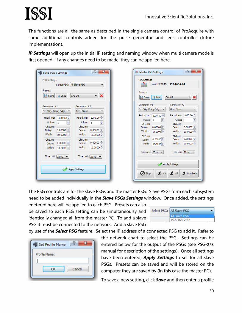
The functions are all the same as described in the single camera control of ProAcquire with some additional controls added for the pulse generator and lens controller (future implementation).
IP Settings will open up the initial IP setting and naming window when multi camera mode is first opened. If any changes need to be made, they can be applied here.
The PSG controls are for the slave PSGs and the master PSG. Slave PSGs form each subsystem need to be added individually in the Slave PSGs Settings window. Once added, the settings enetered here will be applied to each PSG. Presets can also be saved so each PSG setting can be simultaneoulsy and identically changed all from the master PC. To add a slave PSG it must be connected to the network. Add a slave PSG by use of the Select PSG feature. Select the IP address of a connected PSG to add it. Refer to
the network chart to select the PSG. Settings can be entered below for the output of the PSGs (see PSG-2/3 manual for description of the settings). Once all settings have been entered, Apply Settings to set for all slave PSGs. Presets can be saved and will be stored on the computer they are saved by (in this case the master PC).
To save a new setting, click Save and then enter a profile
30

Innovative Scientific Solutions, Inc.
name.
To load a setting, select the desired setting from the drop-down list and press.
The button will delete the selected preset.
In this configuration, the slave PSGs will always be triggered by the master so they are always used in Ext. Trigger mode. The master PSG can be started from the Master PSG Settings wnidow which will then trigger all PSGs for each susbsystem simlutaneously.
ISSI LC’s refers to lens controllers (LC-1 and LC-2) that will be implemented into the multi control software similar to the PSG in future upgrades.
On Top will make the ProAcquire Multicam will make the program remain on top of all other programs on the desktop.
CamStatus will open the Cam Status List window showing all cameras connected via multicamera and their names and status.
Help will bring up the help file for ProAcquire Multicam.
The Camera Settings toolbar controls the acquisition of all of the connected cameras.
Exposure, us is the exposure time of the cameras in microseconds. Leave this checked to edit
the exposure time. The button puts the cameras into external trigger mode and they
will wait for their trigger pulse before framing. The button puts the camera into external pulse width mode. This means that the exposure time of the camera is taken from the pulse width of an external TTL pulse width. This could be from the PSG.
The Frames and Average fuction the same way as they are described above for ProAcquire.
31

Innovative Scientific Solutions, Inc.
The bottom buttons are the signal/reference image display, overclocked mode and LUT respectively. All are described earlier.
Sync Settings will synchronize all camera settings to all slave computers. The screen on the slave computers ProAcqurie will update automatically when this button is clicked.
Clicking Preview or Capture in ProAcquire Multicam will put all cameras connected via the software into those modes. While the cameras are capturing data, the progress for all connected cameras will be shown in the Cam Status List window.
Another additional feature of ProAcquire Multicam is the log file generation. If Logging is checked, a log file wil be saved with the images on the master PC. There is a section for notes below the file path for the log file (use same file path as image save). These notes will be saved as comments in the log file. The log file will display the date and time, list of connecte PCs (by their NIC IP address), list of slave PSGs, the master PSG and the settings entered in the multi camera settings.
This is a useful feature for note taking during a test through a range of test conditions.
To trigger the entire system, the master PSG can be controlled right from the control panel of ProAcquire Multicam in the Master PSG Run/Stop toolbar.
The purpose of the multi camera software is to streamline the system and make it faster and easier to use and minimizing user mistakes. Multi camera software gives the master operator
32

Innovative Scientific Solutions, Inc.
complete control of the system, leading to less time spent in the facility and less confusion while tests are running.
33

Innovative Scientific Solutions, Inc.
Export Disclaimer:
Any and all underlying information and technology contained in this document may be subject to U.S. export controls, including the Export Administration Act (50 U.S.C. Appx. §§ 2401 et seq.) and the Export Administration Regulations ("EAR", 50 C.F.R. Parts 730-774), and may be subject to export or import regulations in other countries. You are responsible for complying with all trade regulations and laws both foreign and domestic. Except as authorized by law or distributor agreement with ISSI, you agree and warrant not to export or re-export the information to any country, or to any person, entity, or end-user subject to U.S. export controls, including without limitation persons or entities listed on the U.S. Department of Commerce Bureau of Export Administration's Denied Parties List and the U.S. Department of Treasury's Specially Designated Nationals. You further represent and warrant that no U.S. federal agency has suspended, revoked, or denied your export privileges.
34

Innovative Scientific Solutions, Inc.
SOFTWARE LICENSE AGREEMENT AND LIMITED WARRANTY This License Agreement is between you (“Customer”) and ISSI, the author of the ISSI Workbook software and governs your use of the program, example results, and documentation (all of which are referred to herein as the "Software"). THIS IS A LEGAL AGREEMENT BETWEEN YOU (EITHER AN INDIVIDUAL OR AN ENTITY), THE END USER, AND ISSI. IF YOU DO NOT AGREE TO THE TERMS OF THIS AGREEMENT, PROMPTLY RETURN THE DISKS AND ACCOMPANYING ITEMS TO ISSI, AND/OR DO NOT DOWNLOAD THE SOFTWARE FROM OUR WEB SITE AND/OR DO NOT INSTALL THE SOFTWARE. 1. Grant of License ISSI grants to you a non-exclusive, non-transferable license, without right to sublicense, distribute or modify, for you and your employees to use the enclosed software and related documentation (collectively the "Product" or the “Software”) as delivered by ISSI only at one location for the testing and evaluation. If the terms of this license agreement are violated, ISSI immediately terminates said license and the customer is subject to the liability of any harm done to ISSI. 2. Title The product is copyrighted by ISSI. ISSI retains all rights, title, and ownership of the Product and all subsequent full or partial copies and derivatives of the Product, made by you or ISSI, including translations, compilations, partial copies, modifications, updates and know-how in connection there with, regardless of the form or media in or on which the same may exist. This license is not a sale of the Product or any copy or derivative. You shall have no right to reproduce any full or partial copies of the Product. You agree not to take any steps, such as reverse assembly or reverse compilation, to derive a source code equivalent of any software contained in the product. You also agree to destroy licensed data in all forms upon termination of said license or receipt of released program code. 3. Confidentiality You agree that the product, and other information, technical data, or know-how (including documentation) related to the Product (including the existence of the product and the results of use or testing), shall be considered Confidential Information of ISSI. You agree to protect the confidentiality of all Confidential Information of ISSI, and not to disclose the Confidential Information to any other party without the written permission of ISSI. Unauthorized use or disclosure of the Product may cause irreparable harm to ISSI. You agree promptly to report any unauthorized use or disclosure to ISSI. 4. Warranty of Functionality ISSI hereby represents and warrants that ISSI is the owner of the Product or otherwise has the right to grant to you and your employees the rights set forth in this Agreement. THE PRODUCT IS PROVIDED "AS IS". THERE ARE NO WARRANTIES UNDER THIS AGREEMENT, AND ISSI DISCLAIMS ANY IMPLIED WARRANTY OF MERCHANTABILITY OR FITNESS FOR PARTICULAR PURPOSE. In the
35

Innovative Scientific Solutions, Inc.
event of any breach or alleged breach of this warranty, you shall promptly notify ISSI and return the Product to ISSI at your expense. Your sole remedy shall be that ISSI shall correct the Product so that it operates according to the warranty. This warranty shall not apply to the Product if modified by anyone or if used improperly or with, on, in an operating environment not approved by ISSI. 5. Limitation of Liability IN NO EVENT SHALL ISSI BE LIABLE FOR ANY LOSS OF PROFITS, LOSS OF USE, SPECIAL, INCIDENTAL OR CONSEQUENTIAL DAMAGES PURSUANT TO THIS AGREEMENT. ISSI shall not be responsible for, and shall not pay, any amount of incidental, consequential or other indirect damages, whether based on lost revenue or otherwise, regardless of whether ISSI was advised of the possibility of such losses in advance. In no event shall ISSI's liability hereunder exceed the amount of license fees paid by you, regardless of whether your claim is based on contract, tort, strict liability, product liability or otherwise. 6. Product Maintenance During the Warranty Period, ISSI shall provide to you any new, corrected or enhanced version of the Product as created by ISSI. Such enhancement shall include all modifications to the Product which increase the speed, efficiency or ease of use of the Product, or add additional capabilities or functionality to the Product, but shall not include any substantially new or rewritten version of the Product. These updates will require Internet Access to our web site to automatically validate your License Key and provide update support. After expiration of the Warranty Period, you may continue to receive maintenance support. The charge for such optional maintenance support shall be ISSI's regular list price for maintenance and support for the Product as published from time to time by ISSI. You will need to notify ISSI in writing if you desire to receive optional maintenance. If you fail to take optional maintenance and later elect to receive it, ISSI reserves the right to charge you their standard maintenance fees for the period of the lapse in maintenance. ISSI may elect to discontinue maintenance at any time upon notice to you, and refund of any then unearned maintenance fees. 7. Proprietary Rights Exclusion ISSI makes no representation or warranty that the Product, or products developed using the Product, do not infringe any proprietary rights of any third parties. You shall assume sole responsibility for any such infringement. 8. Indemnification You hereby agree to indemnify, defend and hold ISSI harmless from and against any and all claims, actions, suits, liabilities, judgments, losses, damages, attorneys' fees and other expenses of every nature and character by reason of this Agreement or use by you of products utilizing the Product. 9. Export Restrictions
36

Innovative Scientific Solutions, Inc.
You shall not export, directly or indirectly, any Product or products developed using the Product to any country for which the laws of the United States or the regulations of any U.S. agency requires an export license or other governmental approval, without first obtaining such license or approval. You shall strictly comply with all such restrictions. You agree to indemnify and hold ISSI harmless against all losses, damages, penalties, or causes of action resulting from a violation of this Section. 10. Anti-Piracy and License Activation You must not engage in the distribution of pirated software or hardware. Use of the Product may be limited to the first 14 days after the end user first use the software, unless the end user activates the Product, as described in and by the Product. Certain ISSI products may use technological measures for copy protection. In that event, you will not be able to use the Product if you do not fully comply with the Product Activation Procedures. Product Activation will take place during initial launch of the product, installation on a different system, or replacement of the installed operating system or certain hardware changes. 11. Governing Law The validity, performance, construction and interpretation of this Agreement shall be governed by laws of the state of Ohio, United States of America, excluding its conflicts of laws rules, as applied to agreements entered into in Ohio between Ohio residents. 12. High risk activities The software and/or hardware supplied by ISSI is not fault-tolerant and is not designed, manufactured or intended for use or resale as on-line control or equipment in hazardous environments requiring fail-safe performance in which the failure of software and/or hardware could lead directly to death, personal injury, or severe physical or environmental damage ("high risk activity"). ISSI and its suppliers specifically disclaim any express or implied warranties of fitness for high risk activities. Should you have any questions concerning this Agreement, please write to: ISSI, 7610 McEwen Road, Dayton, Ohio 45459
37