Embed Size (px)
Citation preview

Pro Micro & Fio V3 Hookup Guide alearn.sparkfun.com tutorial
Available online at: http://sfe.io/t121
Contents
IntroductionHardware Overview: Pro MicroHardware Overview: Fio v3Installing: WindowsInstalling: Mac & LinuxExample 1: Blinkies!Example 2: HID Mouse and KeyboardTroubleshooting and FAQResources and Going Further
Introduction
Welcome to the new frontier of Arduino-compatible boards, made possible by the ATmega32U4. Nolonger does your Arduino need to be harnessed by an FTDI Cable, or an ATmega8U2, or any chipwho’s sole purpose is acting as an intermediary between your Arduino and your computer.
Pro Micro
The SparkFun Pro Micro [ 3.3V/8MHz and 5V/16MHz ] is a really cool, little development board. It’s anArduino-compatible microcontroller, micro-sized, and it accomplishes with one single chip what oldArduino Unos, Duemilanoves, and Diecimeillas could never dream of: true USB functionality.
Page 1 of 33
Pro Micro - 3.3V/8MHz
DEV-12587$19.9513Favorited Favorite 23Wish List
Page 2 of 33
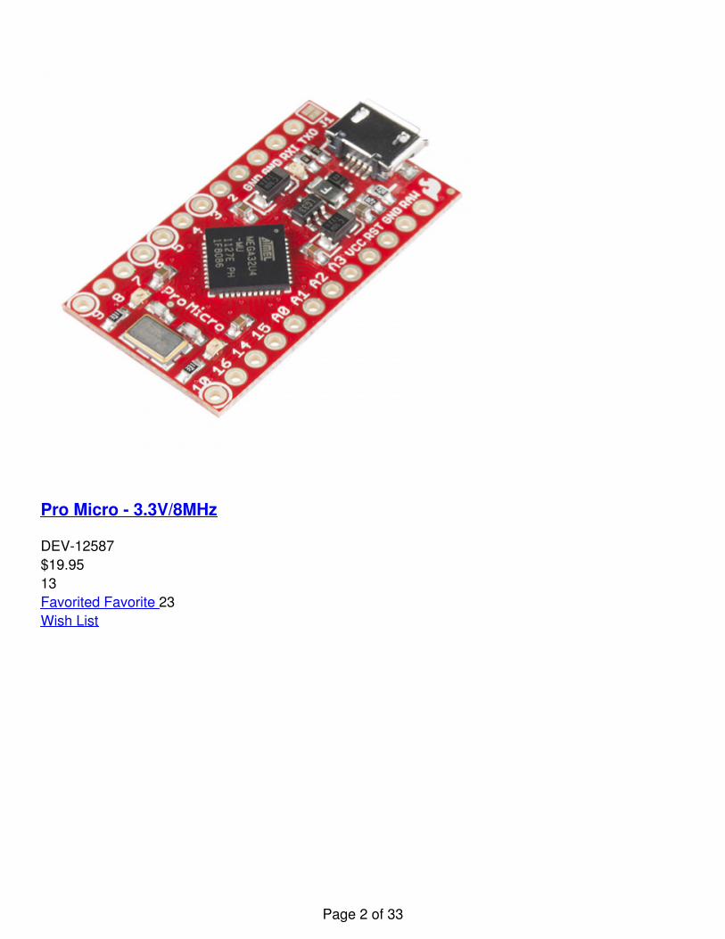
Pro Micro - 5V/16MHz
DEV-12640$19.9568Favorited Favorite 45Wish List
FioV3
This tutorial also covers the Fio v3, which works a lot like the Pro Micro but adds features like easyXBee interfacing and LiPo charging.
Page 3 of 33
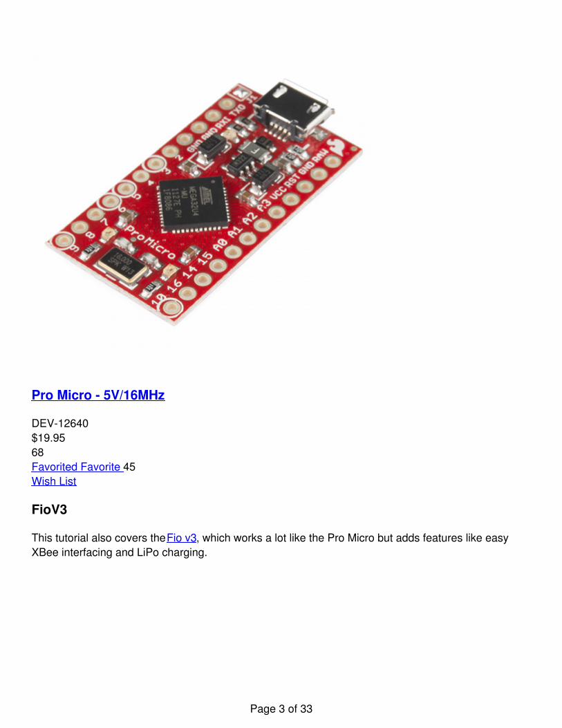
Fio v3 - ATmega32U4
DEV-11520$34.957Favorited Favorite 8Wish List
Covered In This Tutorial
This tutorial aims to introduce you to both the hardware and firmware sides of the Pro Micro (and Fiov3). We’ll also dedicate a few pages to helping install the boards on Windows and Mac. Here’s asummary of what will be covered:
Hardware Overview: Pro Micro – An overview of the pinout and hardware features of the ProMicro.Hardware Overview: Fio v3 – An overview of the pinout and hardware features of the Fio v3.Installing on Windows – How to install the drivers and Arduino addon on Windows.Installing on Mac/Linux – How to install the drivers and Arduino addon on Mac.Example 1: Blinkies – A simple “Hello, world” sketch specifically suited to the Pro Micro and Fiov3.Example 2: HID Mouse and Keyboard – An introduction to the HID USB capability of the Pro
Page 4 of 33
Micro. How to emulate USB keyboards and mice!Troubleshooting and FAQ – Helpful troubleshooting tips and tricks for getting the most out of thePro Micro.
Suggested Reading
Before delving into this tutorial, here are some concepts you should be familiar with. If you’re not,consider checking out the related tutorial first.
What is Arduino? – An introduction to the Arduino platform and IDE.How to Install Arduino – A general installation guide for Arduino.Serial Communication – Serial is a great, easy-to-use communication protocol.
Hardware Overview: Pro Micro
Before we get into installing and using the Pro Micro, let’s quickly look at the board – examine itsinputs, outputs, and other hardware quirks.
The Pinout
All of the Pro Micro’s I/O and power pins are broken out to two, parallel headers. Some pins are forpower input or output, other pins are dedicated I/O pins. Further, the I/O pins can have specialabilities, like analog input. Here’s a map of which pin is where, and what special hardware functions itmay have:
Page 5 of 33
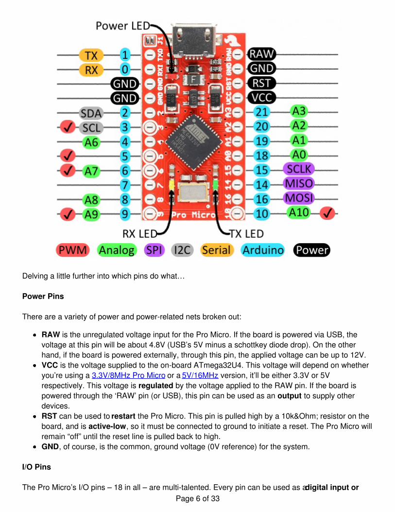
Delving a little further into which pins do what…
Power Pins
There are a variety of power and power-related nets broken out:
RAW is the unregulated voltage input for the Pro Micro. If the board is powered via USB, thevoltage at this pin will be about 4.8V (USB’s 5V minus a schottkey diode drop). On the otherhand, if the board is powered externally, through this pin, the applied voltage can be up to 12V.VCC is the voltage supplied to the on-board ATmega32U4. This voltage will depend on whetheryou’re using a 3.3V/8MHz Pro Micro or a 5V/16MHz version, it’ll be either 3.3V or 5Vrespectively. This voltage is regulated by the voltage applied to the RAW pin. If the board ispowered through the ‘RAW’ pin (or USB), this pin can be used as an output to supply otherdevices.RST can be used to restart the Pro Micro. This pin is pulled high by a 10k&Ohm; resistor on theboard, and is active-low, so it must be connected to ground to initiate a reset. The Pro Micro willremain “off” until the reset line is pulled back to high.GND, of course, is the common, ground voltage (0V reference) for the system.
I/O Pins
The Pro Micro’s I/O pins – 18 in all – are multi-talented. Every pin can be used as a digital input orPage 6 of 33
output, for blinking LEDs or reading button presses. These pins are referenced in the Arduino IDE viaan integer value between 0 and 21. (The A0-A3 pins can be referenced digitally using either theiranalog or digital pin number).
Nine pins feature analog to digital converters (ADCs) and can be used as analog inputs. These areuseful for reading potentiometers or other analog devices using the analogRead([pin]) function.
There are five pins with pulse width modulation (PWM) functionality, which allows for a form of analogoutput using the analogWrite([pin], [value]) function. These pins are indicated on-board with a faint, whitecircle around them.
There are hardware UART (serial), I2C, and SPI pins available as well. These can be used to interfacewith digital devices like serial LCDs, XBees, IMUs, and other serial sensors.
The Pro Micro has five external interrupts, which allow you to instantly trigger a function when a pingoes either high or low (or both). If you attach an interrupt to an interrupt-enabled pin, you’ll need toknow the specific interrupt that pin triggers: pin 3 maps to interrupt 0, pin 2 is interrupt 1, pin 0 isinterrupt 2, pin 1 is interrupt 3, and pin 7 is interrupt 4.
On-Board LEDs
There are three LEDs on the Pro Micro. One red LED indicates whether power is present.
The other two LEDs help indicate when data is transferring over USB. A yellow LED represents USBdata coming into (RX) the the Pro Micro, and a green LED indicates USB data going out (TX).
3.3V or 5V? 8MHz or 16MHz?
Pro Micros come in two flavors, which vary by system voltage and operating frequency. The standard5V Pro Micro runs at 16MHz, and is very comparable to an Arduino Leonardo, while the 3.3V versionof the Pro Micro runs at half the speed (to remain in the safe operating zone at the lower voltage) –8MHz.
The operating voltage of your Pro Micro determines the maximum allowable voltage on any of the I/Opins. For example, if you have a 3.3V Pro Micro, don’t interface it with something that outputs 5V.
Page 7 of 33
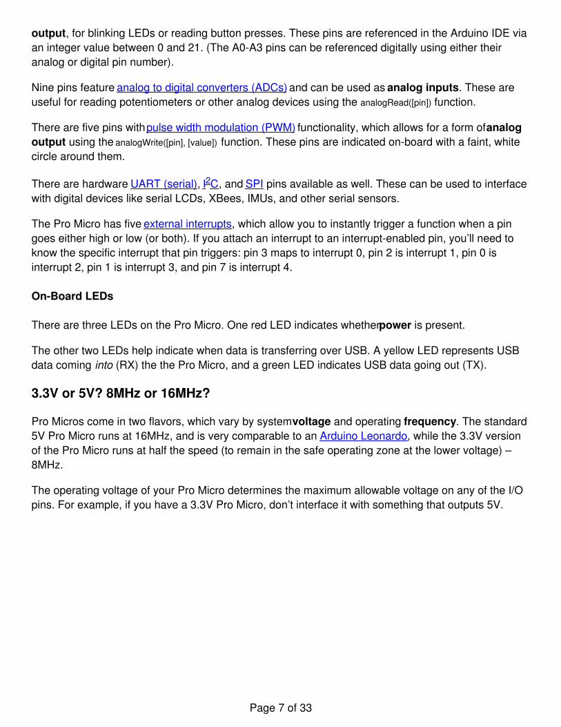
Don’t forget which version you have! We’ll need to differentiate between the two when we get touploading code in Arduino. If you’re not sure which version you have, check the back corner of theboard. One of two boxes should be checked to indicate the operating voltage.
How to Power the Pro Micro
As the Pro Micro’s main feature is its innate USB functionality, the most common way to power it is viaUSB. In this setup, a 5V Pro Micro will be powered directly from the USB bus and a 3.3V Pro Micro willregulate the 5V supply coming in from USB down. The other end of the USB cable can be connectedto either a computer, USB hub, or a USB wall adapter, which can (in most cases) provide more power.
Alternatively, if your Pro Micro is living out in the wild, out of reach of USB cables, it can be poweredthrough either the ‘RAW’ or ‘VCC’ pins. A supply going into the ‘RAW’ pin will be regulated down tothe correct operating voltage (5V or 3.3V). To be safe, it shouldn’t be any higher than 12V, and itshould be at least 1V more than the Pro Micro’s operating voltage (e.g. >6V for a 5V Pro Micro).
Page 8 of 33
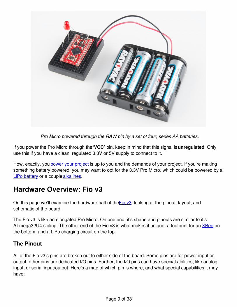
Pro Micro powered through the RAW pin by a set of four, series AA batteries.
If you power the Pro Micro through the ‘VCC’ pin, keep in mind that this signal is unregulated. Onlyuse this if you have a clean, regulated 3.3V or 5V supply to connect to it.
How, exactly, you power your project is up to you and the demands of your project. If you’re makingsomething battery powered, you may want to opt for the 3.3V Pro Micro, which could be powered by aLiPo battery or a couple alkalines.
Hardware Overview: Fio v3
On this page we’ll examine the hardware half of the Fio v3, looking at the pinout, layout, andschematic of the board.
The Fio v3 is like an elongated Pro Micro. On one end, it’s shape and pinouts are similar to it’sATmega32U4 sibling. The other end of the Fio v3 is what makes it unique: a footprint for an XBee onthe bottom, and a LiPo charging circuit on the top.
The Pinout
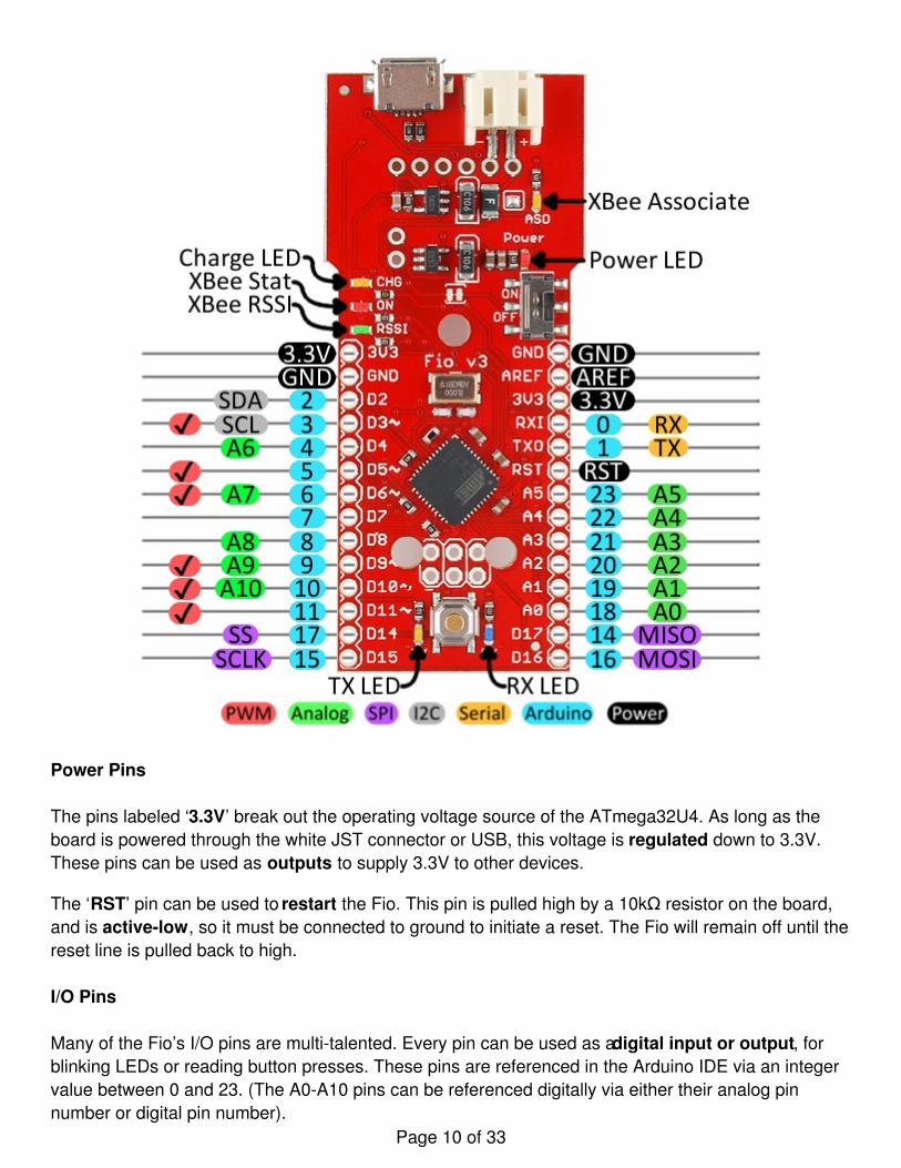
All of the Fio v3’s pins are broken out to either side of the board. Some pins are for power input oroutput, other pins are dedicated I/O pins. Further, the I/O pins can have special abilities, like analoginput, or serial input/output. Here’s a map of which pin is where, and what special capabilities it mayhave:
Page 9 of 33
Power Pins
The pins labeled ‘3.3V’ break out the operating voltage source of the ATmega32U4. As long as theboard is powered through the white JST connector or USB, this voltage is regulated down to 3.3V.These pins can be used as outputs to supply 3.3V to other devices.
The ‘RST’ pin can be used to restart the Fio. This pin is pulled high by a 10kΩ resistor on the board,and is active-low, so it must be connected to ground to initiate a reset. The Fio will remain off until thereset line is pulled back to high.
I/O Pins
Many of the Fio’s I/O pins are multi-talented. Every pin can be used as a digital input or output, forblinking LEDs or reading button presses. These pins are referenced in the Arduino IDE via an integervalue between 0 and 23. (The A0-A10 pins can be referenced digitally via either their analog pinnumber or digital pin number).
Page 10 of 33
Eleven pins feature analog to digital converters (ADCs) and can be used as analog inputs. These areuseful for reading potentiometers or other analog devices using the analogRead([pin]) function.
There are six pins with pulse width modulation (PWM) functionality, which allows for a form of analogoutput using the analogWrite([pin], [value]) function. These pins are indicated on-board with a faint whitecircle around the pin.
There are also hardware UART (serial), I2C, and SPI pins available. These can be used to interfacewith digital devices like serial LCDs, IMUs, and other serial sensors.
The Fio v3 has five external interrupts, which allow you to instantly trigger a function when a pin goeseither high or low (or both). If you attach an interrupt to an interrupt-enabled pin, you’ll need to knowthe specific interrupt that pin triggers: pin 3 maps to interrupt 0, pin 2 is interrupt 1, pin 0 is interrupt 2,pin 1 is interrupt 3, and pin 7 is interrupt 4.
On-Board LEDs
There are a variety of LEDs on the Fio, the simplest of which is the red power indicator. Two LEDstowards the bottom – labeled RX and TX – help indicate when data is transferring to and from the Fiothrough USB. A blue LED represents USB data coming into (‘RX’) the the Pro Micro, and a yellowLED indicates USB data going out (‘TX’).
There are three LEDs tied to the XBee interface in particular: stat, RSSI, and associate. The red LEDlabeled ‘ON’ is connected to the XBee’s pin 13 – DIO9 – which is, by default, set to indicate the XBeemodule’s ON/OFF status. An ‘RSSI’ LED connects to XBee pin 6 (PWM0) which defaults to indicateRSSI (received signal strength) – a brighter LED means a stronger received signal. Lastly, the ‘ASO’LED connects to XBee pin 15, which will blink if the module is associated.
Finally, there’s a yellow LED labeled ‘CHG’ which indicates if an attached lithium polymer battery ischarging. If a battery is not connected to the Fio, the LED will be in an undefined state, and most likelybe illuminated.
How to Power the Fio v3
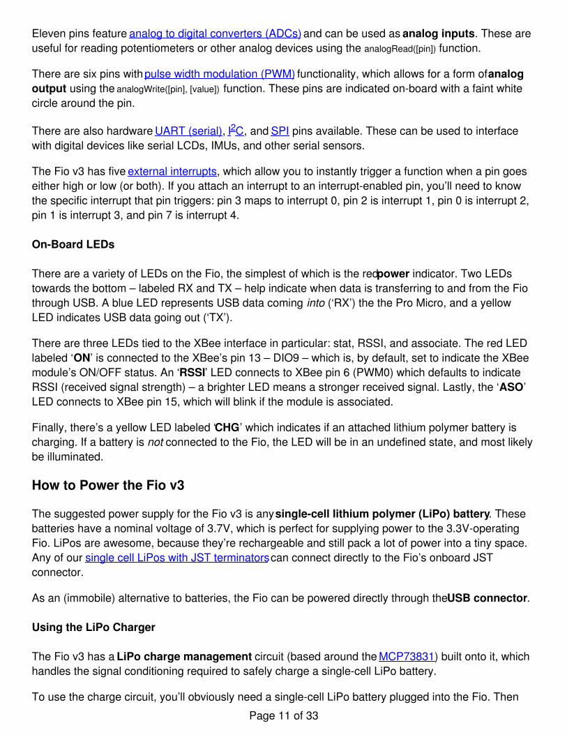
The suggested power supply for the Fio v3 is any single-cell lithium polymer (LiPo) battery. Thesebatteries have a nominal voltage of 3.7V, which is perfect for supplying power to the 3.3V-operatingFio. LiPos are awesome, because they’re rechargeable and still pack a lot of power into a tiny space.Any of our single cell LiPos with JST terminators can connect directly to the Fio’s onboard JSTconnector.
As an (immobile) alternative to batteries, the Fio can be powered directly through the USB connector.
Using the LiPo Charger
The Fio v3 has a LiPo charge management circuit (based around the MCP73831) built onto it, whichhandles the signal conditioning required to safely charge a single-cell LiPo battery.
To use the charge circuit, you’ll obviously need a single-cell LiPo battery plugged into the Fio. Then
Page 11 of 33
connect the board up via USB, so the charge circuit has a primary voltage source to supply charge tothe battery.
The ‘CHG’ LED will indicate the status of the battery charge. If it’s on, the battery is still charging.Once the ‘CHG’ LED goes off, the battery is fully charged.
The charge circuit is programmed to charge the battery at 500mA, so, to be safe, the battery shouldbe no smaller than 500mAH in capacity.
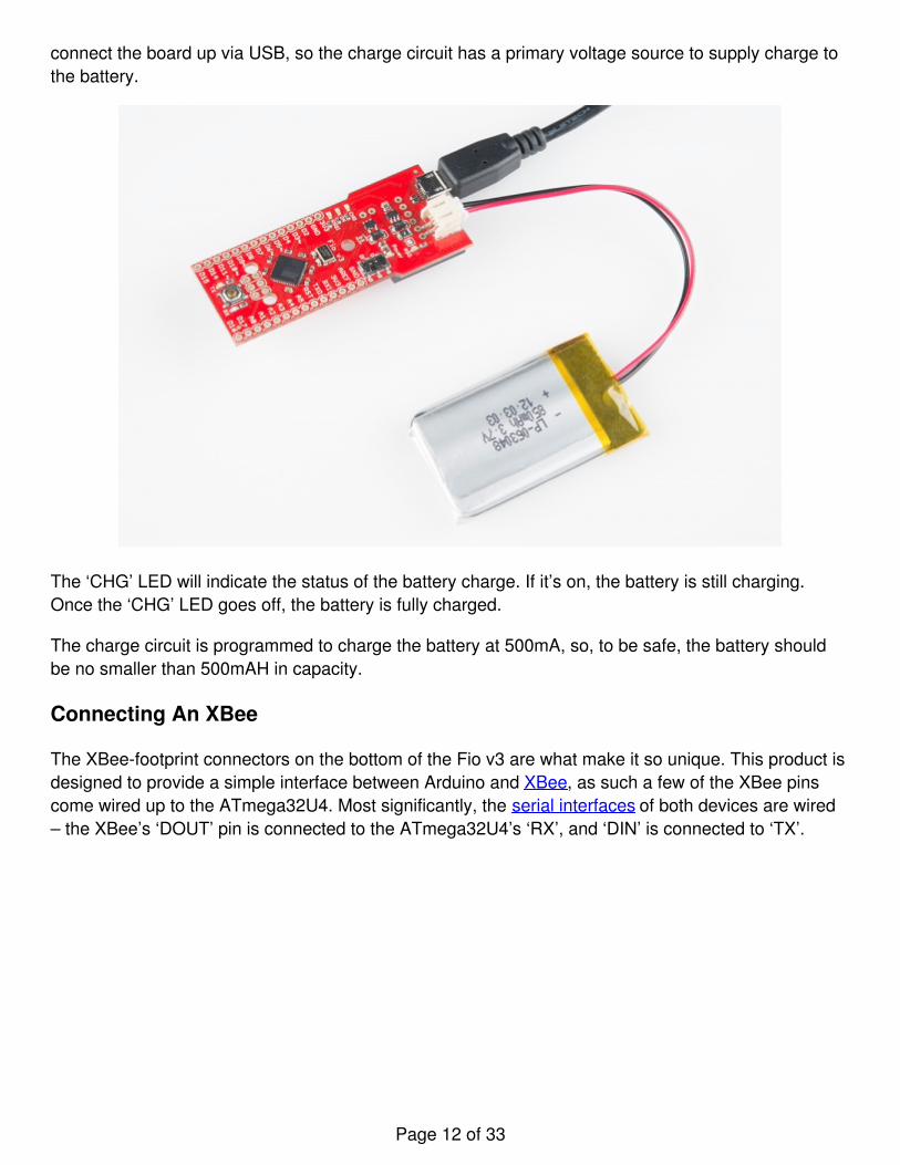
Connecting An XBee
The XBee-footprint connectors on the bottom of the Fio v3 are what make it so unique. This product isdesigned to provide a simple interface between Arduino and XBee, as such a few of the XBee pinscome wired up to the ATmega32U4. Most significantly, the serial interfaces of both devices are wired– the XBee’s ‘DOUT’ pin is connected to the ATmega32U4’s ‘RX’, and ‘DIN’ is connected to ‘TX’.
Page 12 of 33
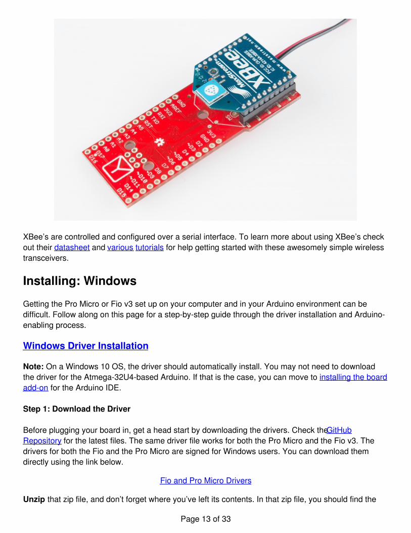
XBee’s are controlled and configured over a serial interface. To learn more about using XBee’s checkout their datasheet and various tutorials for help getting started with these awesomely simple wirelesstransceivers.
Installing: Windows
Getting the Pro Micro or Fio v3 set up on your computer and in your Arduino environment can bedifficult. Follow along on this page for a step-by-step guide through the driver installation and Arduino-enabling process.
Windows Driver Installation
Note: On a Windows 10 OS, the driver should automatically install. You may not need to downloadthe driver for the Atmega-32U4-based Arduino. If that is the case, you can move to installing the boardadd-on for the Arduino IDE.
Step 1: Download the Driver
Before plugging your board in, get a head start by downloading the drivers. Check the GitHubRepository for the latest files. The same driver file works for both the Pro Micro and the Fio v3. Thedrivers for both the Fio and the Pro Micro are signed for Windows users. You can download themdirectly using the link below.
Fio and Pro Micro Drivers
Unzip that zip file, and don’t forget where you’ve left its contents. In that zip file, you should find the
Page 13 of 33
.inf and .cat files, which contains all the information Windows needs to install the Pro Micro’s driver.The sparkfun.inf driver and sparkfun.cat digitally signed catalog file will be found in Arduino_Boards-master/sparkfun/avr/signed_driver .
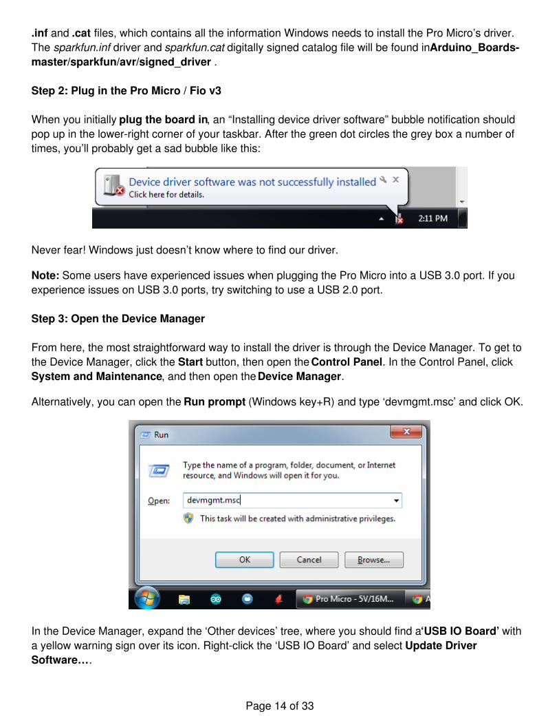
Step 2: Plug in the Pro Micro / Fio v3
When you initially plug the board in, an “Installing device driver software” bubble notification shouldpop up in the lower-right corner of your taskbar. After the green dot circles the grey box a number oftimes, you’ll probably get a sad bubble like this:
Never fear! Windows just doesn’t know where to find our driver.
Note: Some users have experienced issues when plugging the Pro Micro into a USB 3.0 port. If youexperience issues on USB 3.0 ports, try switching to use a USB 2.0 port.
Step 3: Open the Device Manager
From here, the most straightforward way to install the driver is through the Device Manager. To get tothe Device Manager, click the Start button, then open the Control Panel. In the Control Panel, clickSystem and Maintenance, and then open the Device Manager.
Alternatively, you can open the Run prompt (Windows key+R) and type ‘devmgmt.msc’ and click OK.
In the Device Manager, expand the ‘Other devices’ tree, where you should find a ‘USB IO Board’ witha yellow warning sign over its icon. Right-click the ‘USB IO Board’ and select Update DriverSoftware….
Page 14 of 33
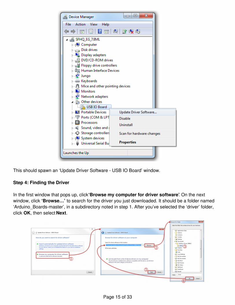
This should spawn an ‘Update Driver Software - USB IO Board’ window.
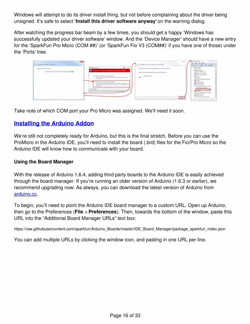
Step 4: Finding the Driver
In the first window that pops up, click ‘Browse my computer for driver software’. On the nextwindow, click ‘Browse…’ to search for the driver you just downloaded. It should be a folder named‘Arduino_Boards-master’, in a subdirectory noted in step 1. After you’ve selected the ‘driver’ folder,click OK, then select Next.
Page 15 of 33
Windows will attempt to do its driver install thing, but not before complaining about the driver beingunsigned. It’s safe to select ‘Install this driver software anyway’ on the warning dialog.
After watching the progress bar beam by a few times, you should get a happy ‘Windows hassuccessfully updated your driver software’ window. And the ‘Device Manager’ should have a new entryfor the ‘SparkFun Pro Micro (COM ##)’ (or ‘SparkFun Fio V3 (COM##)’ if you have one of those) underthe ‘Ports’ tree.
Take note of which COM port your Pro Micro was assigned. We’ll need it soon.
Installing the Arduino Addon
We’re still not completely ready for Arduino, but this is the final stretch. Before you can use theProMicro in the Arduino IDE, you’ll need to install the board (.brd) files for the Fio/Pro Micro so theArduino IDE will know how to communicate with your board.
Using the Board Manager
With the release of Arduino 1.6.4, adding third party boards to the Arduino IDE is easily achievedthrough the board manager. If you’re running an older version of Arduino (1.6.3 or earlier), werecommend upgrading now. As always, you can download the latest version of Arduino fromarduino.cc.
To begin, you’ll need to point the Arduino IDE board manager to a custom URL. Open up Arduino,then go to the Preferences (File > Preferences). Then, towards the bottom of the window, paste thisURL into the “Additional Board Manager URLs” text box:
https://raw.githubusercontent.com/sparkfun/Arduino_Boards/master/IDE_Board_Manager/package_sparkfun_index.json
You can add multiple URLs by clicking the window icon, and pasting in one URL per line.
Page 16 of 33

Click OK. Then open the Board Manager by clicking Tools, then hovering over the Board selection taband clicking Board Manager.
Search for ‘sparkfun’ in the Board Manager. You should see the SparkFun AVR Boards packageappear. Click install, wait a few moments, and all the .brd files you’ll need should be installed,indicated by the blue ‘Installed’ that is printed next to the package.
Page 17 of 33
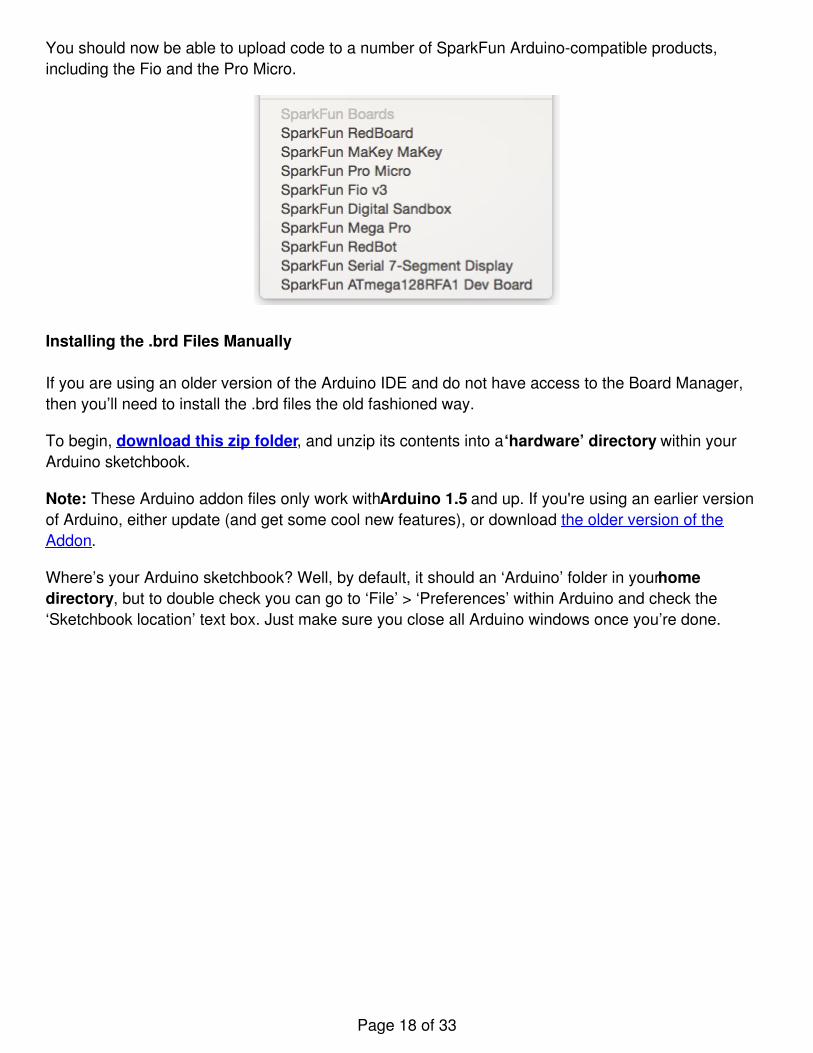
You should now be able to upload code to a number of SparkFun Arduino-compatible products,including the Fio and the Pro Micro.
Installing the .brd Files Manually
If you are using an older version of the Arduino IDE and do not have access to the Board Manager,then you’ll need to install the .brd files the old fashioned way.
To begin, download this zip folder, and unzip its contents into a ‘hardware’ directory within yourArduino sketchbook.
Note: These Arduino addon files only work with Arduino 1.5 and up. If you're using an earlier versionof Arduino, either update (and get some cool new features), or download the older version of theAddon.
Where’s your Arduino sketchbook? Well, by default, it should an ‘Arduino’ folder in your homedirectory, but to double check you can go to ‘File’ > ‘Preferences’ within Arduino and check the‘Sketchbook location’ text box. Just make sure you close all Arduino windows once you’re done.
Page 18 of 33
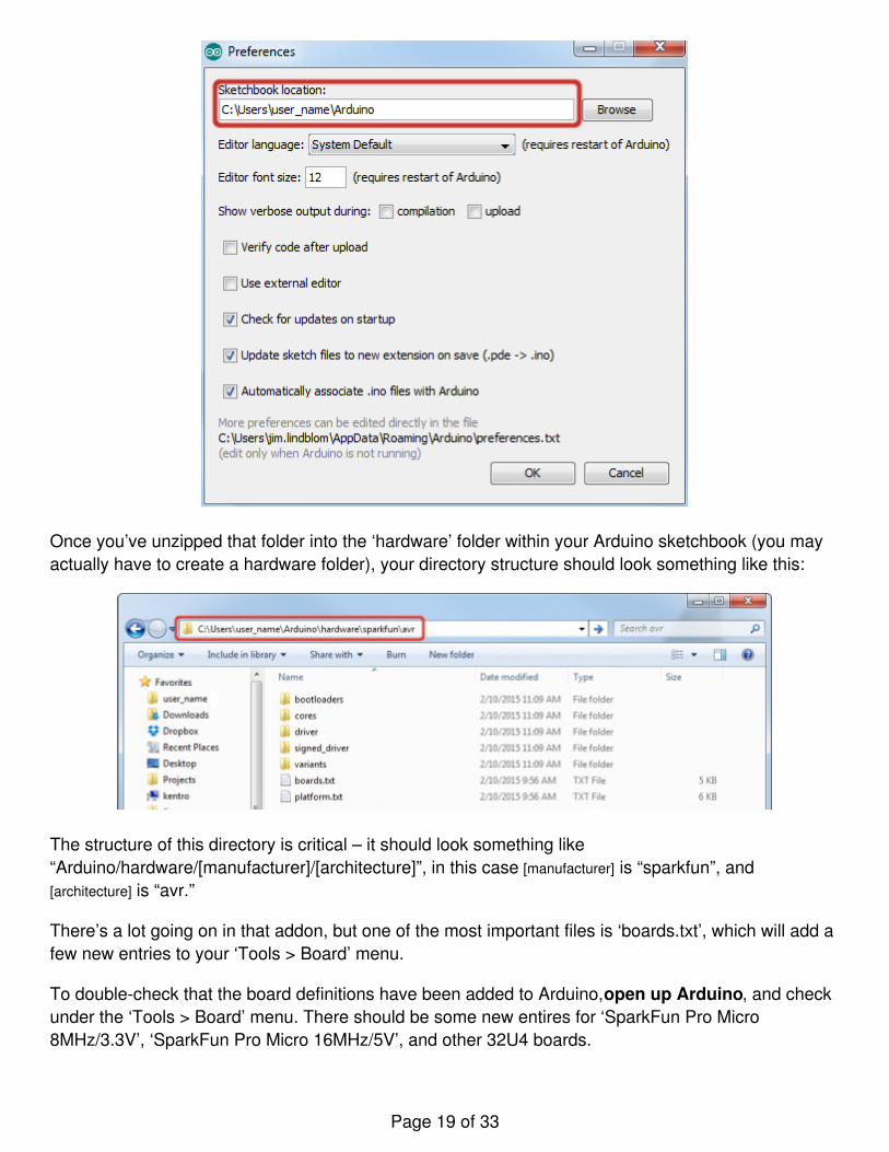
Once you’ve unzipped that folder into the ‘hardware’ folder within your Arduino sketchbook (you mayactually have to create a hardware folder), your directory structure should look something like this:
The structure of this directory is critical – it should look something like“Arduino/hardware/[manufacturer]/[architecture]”, in this case [manufacturer] is “sparkfun”, and[architecture] is “avr.”
There’s a lot going on in that addon, but one of the most important files is ‘boards.txt’, which will add afew new entries to your ‘Tools > Board’ menu.
To double-check that the board definitions have been added to Arduino, open up Arduino, and checkunder the ‘Tools > Board’ menu. There should be some new entires for ‘SparkFun Pro Micro8MHz/3.3V’, ‘SparkFun Pro Micro 16MHz/5V’, and other 32U4 boards.
Page 19 of 33
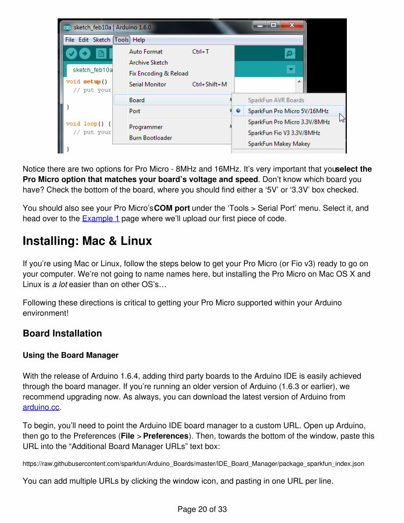
Notice there are two options for Pro Micro - 8MHz and 16MHz. It’s very important that you select thePro Micro option that matches your board’s voltage and speed. Don’t know which board youhave? Check the bottom of the board, where you should find either a ‘5V’ or ‘3.3V’ box checked.
You should also see your Pro Micro’s COM port under the ‘Tools > Serial Port’ menu. Select it, andhead over to the Example 1 page where we’ll upload our first piece of code.
Installing: Mac & Linux
If you’re using Mac or Linux, follow the steps below to get your Pro Micro (or Fio v3) ready to go onyour computer. We’re not going to name names here, but installing the Pro Micro on Mac OS X andLinux is a lot easier than on other OS’s…
Following these directions is critical to getting your Pro Micro supported within your Arduinoenvironment!
Board Installation
Using the Board Manager
With the release of Arduino 1.6.4, adding third party boards to the Arduino IDE is easily achievedthrough the board manager. If you’re running an older version of Arduino (1.6.3 or earlier), werecommend upgrading now. As always, you can download the latest version of Arduino fromarduino.cc.
To begin, you’ll need to point the Arduino IDE board manager to a custom URL. Open up Arduino,then go to the Preferences (File > Preferences). Then, towards the bottom of the window, paste thisURL into the “Additional Board Manager URLs” text box:
https://raw.githubusercontent.com/sparkfun/Arduino_Boards/master/IDE_Board_Manager/package_sparkfun_index.json
You can add multiple URLs by clicking the window icon, and pasting in one URL per line.
Page 20 of 33
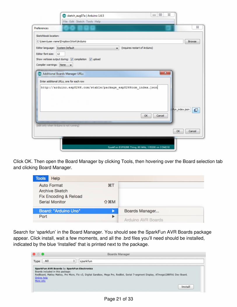
Click OK. Then open the Board Manager by clicking Tools, then hovering over the Board selection taband clicking Board Manager.
Search for ‘sparkfun’ in the Board Manager. You should see the SparkFun AVR Boards packageappear. Click install, wait a few moments, and all the .brd files you’ll need should be installed,indicated by the blue ‘Installed’ that is printed next to the package.
Page 21 of 33
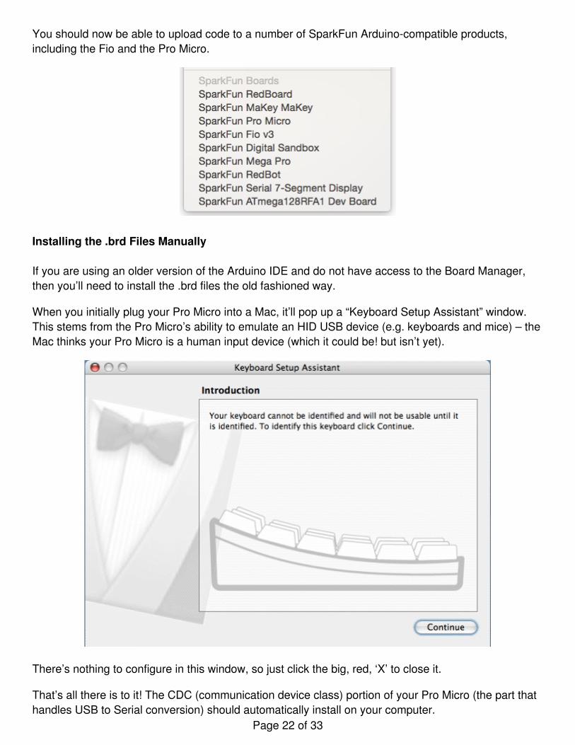
You should now be able to upload code to a number of SparkFun Arduino-compatible products,including the Fio and the Pro Micro.
Installing the .brd Files Manually
If you are using an older version of the Arduino IDE and do not have access to the Board Manager,then you’ll need to install the .brd files the old fashioned way.
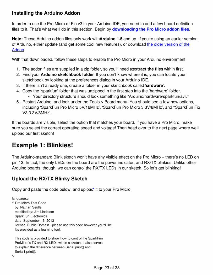
When you initially plug your Pro Micro into a Mac, it’ll pop up a “Keyboard Setup Assistant” window.This stems from the Pro Micro’s ability to emulate an HID USB device (e.g. keyboards and mice) – theMac thinks your Pro Micro is a human input device (which it could be! but isn’t yet).
There’s nothing to configure in this window, so just click the big, red, ‘X’ to close it.
That’s all there is to it! The CDC (communication device class) portion of your Pro Micro (the part thathandles USB to Serial conversion) should automatically install on your computer.
Page 22 of 33
Installing the Arduino Addon
In order to use the Pro Micro or Fio v3 in your Arduino IDE, you need to add a few board definitionfiles to it. That’s what we’ll do in this section. Begin by downloading the Pro Micro addon files.
Note: These Arduino addon files only work with Arduino 1.5 and up. If you're using an earlier versionof Arduino, either update (and get some cool new features), or download the older version of theAddon.
With that downloaded, follow these steps to enable the Pro Micro in your Arduino environment:
1. The addon files are supplied in a zip folder, so you’ll need to extract the files within first.2. Find your Arduino sketchbook folder. If you don’t know where it is, you can locate your
sketchbook by looking at the preferences dialog in your Arduino IDE.3. If there isn’t already one, create a folder in your sketchbook called ‘hardware’.4. Copy the ‘sparkfun’ folder that was unzipped in the first step into the ‘hardware’ folder.
Your directory structure should look something like “Arduino/hardware/sparkfun/avr.”5. Restart Arduino, and look under the Tools > Board menu. You should see a few new options,
including ‘SparkFun Pro Micro 5V/16MHz’, ‘SparkFun Pro Micro 3.3V/8MHz’, and ‘'SparkFun FioV3 3.3V/8MHz’.
If the boards are visible, select the option that matches your board. If you have a Pro Micro, makesure you select the correct operating speed and voltage! Then head over to the next page where we’llupload our first sketch!
Example 1: Blinkies!
The Arduino-standard Blink sketch won’t have any visible effect on the Pro Micro – there’s no LED onpin 13. In fact, the only LEDs on the board are the power indicator, and RX/TX blinkies. Unlike otherArduino boards, though, we can control the RX/TX LEDs in our sketch. So let’s get blinking!
Upload the RX/TX Blinky Sketch
Copy and paste the code below, and upload* it to your Pro Micro.
language:c/* Pro Micro Test Code by: Nathan Seidle modified by: Jim Lindblom SparkFun Electronics date: September 16, 2013 license: Public Domain - please use this code however you'd like. It's provided as a learning tool.
This code is provided to show how to control the SparkFun ProMicro's TX and RX LEDs within a sketch. It also serves to explain the difference between Serial.print() and Serial1.print().*/
Page 23 of 33
int RXLED = 17; // The RX LED has a defined Arduino pin// The TX LED was not so lucky, we'll need to use pre-defined// macros (TXLED1, TXLED0) to control that.// (We could use the same macros for the RX LED too -- RXLED1,// and RXLED0.)
void setup(){ pinMode(RXLED, OUTPUT); // Set RX LED as an output // TX LED is set as an output behind the scenes
Serial.begin(9600); //This pipes to the serial monitor Serial1.begin(9600); //This is the UART, pipes to sensors attached to board}
void loop(){ Serial.println("Hello world"); // Print "Hello World" to the Serial Monitor Serial1.println("Hello!"); // Print "Hello!" over hardware UART
digitalWrite(RXLED, LOW); // set the RX LED ON TXLED0; //TX LED is not tied to a normally controlled pin so a macro is needed, turn LED OFF delay(1000); // wait for a second
digitalWrite(RXLED, HIGH); // set the RX LED OFF TXLED1; //TX LED macro to turn LED ON delay(1000); // wait for a second}
With the code uploaded you should see the RX and TX LEDs take turns blinking on and off everysecond. You can also open up the serial monitor (set to 9600 bps) and see every programmer’sfavorite two-word phrase.
Understanding the Sketch
RX LED
The RX LED is tied to Arduino’s pin 17. You can control it just as you would any other digital pin. Set itas an OUTPUT, and digitalWrite([pin], [level]) it HIGH to turn the LED off or LOW to turn the LED on.
TX LED
The TX LED was not provided as an Arduino-defined pin, unfortunately, so you’ll have to use a pair ofmacros to control it. TXLED1 turns the LED on, and TXLED0 turns the LED off.
Serial Monitor (Serial) and Hardware Serial UART (Serial1)
In that sketch, you’ll also notice a pair of Serial initialization statements: Serial.begin(9600),Serial1.begin(9600). That ‘1’ makes a huge difference. Think of the Pro Micro having two separate serialports. The one without the ‘1’ is for communication to and from the computer over USB; this is what isvisible in the Serial Monitor. The Serial1 port is a bonafide, hardware UART, where your Pro Micro cantalk to any serial-enabled piece of hardware.
Page 24 of 33
If you open up the Serial Monitor, you should only see ‘Hello world’ printed. ‘Hello!’ is being sent outover the hardware UART, where, presumably, nothing is listening. This begs the age-old question: “if aPro Micro is saying ‘Hello!’ over the hardware serial port, and nothing is there to hear it, does the ProMicro really say anything at all?.”
Why Does My Board Re-Enumerate Every Upload?
In order to communicate serially, the Pro Micro emulates a virtual serial port. Actually, it emulatestwo different serial ports – one for the bootloader, and one for the sketch. Since the bootloader andsketch run individually. Only one of these serial ports is visible at any one time.
When you click ‘Upload’ in the Arduino IDE, the Pro Micro resets itself and starts its bootloaderprogram. (The bootloader is a low-level program on the Pro Micro which enables self-programming viaserial.) To our operating system, the bootloader looks like a completely different device, so it gets itsown serial port number. While the Pro Micro is being programmed, the bootloader serial port will beopen. When the sketch upload is finished, the bootloader will exit, that serial port will be closed, andthe regular Pro Micro serial port will open up.
What this all boils down to is the fact that you have to be patient with Pro Micros. Every time youupload a new sketch, your OS will need to work its driver magic before you can open up the COMport. This can take a few seconds after the code has finished uploading.
* Note for Windows users: The first time you upload a sketch, it may fail and give you an error. Ontop of that Windows will pop up that familiar ‘Device driver software was not successfully installed’notification. Don’t let this worry you too much. If you get the error, wait about a minute, and tryuploading again.
Hopefully the upload will succeed the second time, but if it continues to fail, check out the how to enterthe bootloader section of the FAQ. Windows needs to install the same driver we’ve already installedfor the Pro Micro’s bootloader, but it’s unable to get everything set up before the bootloader exits.
Example 2: HID Mouse and Keyboard
By far, the Pro Micro’s most revolutionary feature (as far as Arduinos go) is its true USB functionality.The Pro Micro can be programmed to emulate any USB device you could imagine. You can evenprogram it to act just like a mouse, keyboard, or other HID-class USB device.
What is HID? It’s one of the many defined USB device classes. Every USB device is assigned a class,which defines what its general purpose is. There are loads of classes – printers, hubs, speakers, andwebcams to mention a few, but in this example we’ll be emulating HID – Human Interface Device.The ATmega32U4 takes care of the USB-hardware hurdle, but we’ve still got to clear the firmwareone. Time for some example code!
USB Keyboards Made Simple
To emulate a USB keyboard, we’ll be making use of the Keyboard class. Here are some of the functions
Page 25 of 33
made available to us by this class:
Keyboard.write(char) - This function will send a single character over USB. The character passedcan be any standard, printable, ASCII-defined character: 0-9, a-z, A-Z, space, symbols, etc.Here’s an example line of code:
Keyboard.write('z') // This will send a single 'z' character to your computer.
Keyboard.print(string) - If you need to perform a series a Keyboard.write()’s, consider using just asingle Keyboard.print(). This works similar to Serial.print() – give it a string of characters and it’ll sendthat stream of characters over USB. Keyboard.println(string) is also defined, if you want anewline/linefeed to close out your string. An example:
Keyboard.print("Hello, world"); // This'll send your computer an 'H', followed by 'e', followed by...
Keyboard.press(byte) and Keyboard.release(byte) give you more precise control over key presses.They do exactly what you’d expect. One presses a button down, the other releases a button.Make sure you release any buttons you press, otherwise you’ll encounter some wiggyness onyour computer.
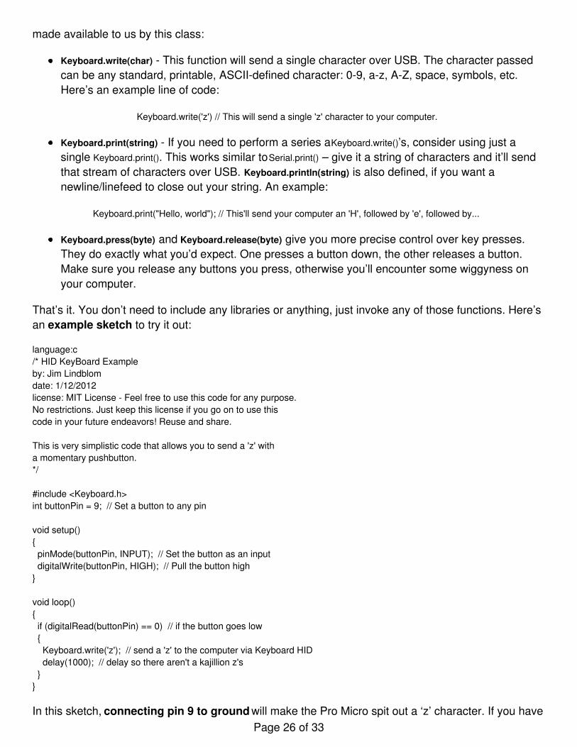
That’s it. You don’t need to include any libraries or anything, just invoke any of those functions. Here’san example sketch to try it out:
language:c/* HID KeyBoard Exampleby: Jim Lindblomdate: 1/12/2012license: MIT License - Feel free to use this code for any purpose.No restrictions. Just keep this license if you go on to use thiscode in your future endeavors! Reuse and share.
This is very simplistic code that allows you to send a 'z' witha momentary pushbutton. */
#include <Keyboard.h>int buttonPin = 9; // Set a button to any pin
void setup(){ pinMode(buttonPin, INPUT); // Set the button as an input digitalWrite(buttonPin, HIGH); // Pull the button high}
void loop(){ if (digitalRead(buttonPin) == 0) // if the button goes low { Keyboard.write('z'); // send a 'z' to the computer via Keyboard HID delay(1000); // delay so there aren't a kajillion z's }}
In this sketch, connecting pin 9 to ground will make the Pro Micro spit out a ‘z’ character. If you havePage 26 of 33
a simple, momentary button handy, tie one end to pin 9 and the other to ground. Otherwise, just usea wire to short 9 to GND.
After a Keyboard.write() or Keyboard.print() function has been performed by the Pro Micro, your computerwill have to decide what to do with it. What your computer does with that character, or string ofcharacters, is entirely dependent on what program it’s running at the time. If you have a text editoropen and active, it’ll print it out there.
USB Mouse Functionality
That covers about half of USB HID library. How about we add a mouse to the mix now? Implementinga USB HID mouse requires a few more functions, but it’s still crazy simple. There are five functionsprovided by Arduino’s HID class that can be used to implement a mouse:
Mouse.move(x, y, wheel) tells the computer to move the mouse a certain number of pixels alongeither the x, y and/or wheel axis. Each variable can be any value between -128 and +127, withnegative numbers moving the cursor down/left, positive numbers move the right/up.
Mouse.press(b) sends a down-click on a button or buttons. The button(s) will remain “pressed”until you call Mouse.release(b). The b variable is a single byte, each bit of which represents adifferent button. You can set it equal to any of the following, or OR (|) them together to clickmultiple buttons at once:
MOUSE_LEFT - Left Mouse buttonMOUSE_RIGHT - Right Mouse buttonMOUSE_MIDDLE - Middle mouse buttonMOUSE_ALL - All three mouse buttons
Mouse.click(b) sends a down-click (press) followed immediately by an up-click (release) onbutton(s) b. For example, to click the left and right buttons simultaneously, try this:
Mouse.click(MOUSE_LEFT | MOUSE_RIGHT); // Press and release the left and right mouse buttons
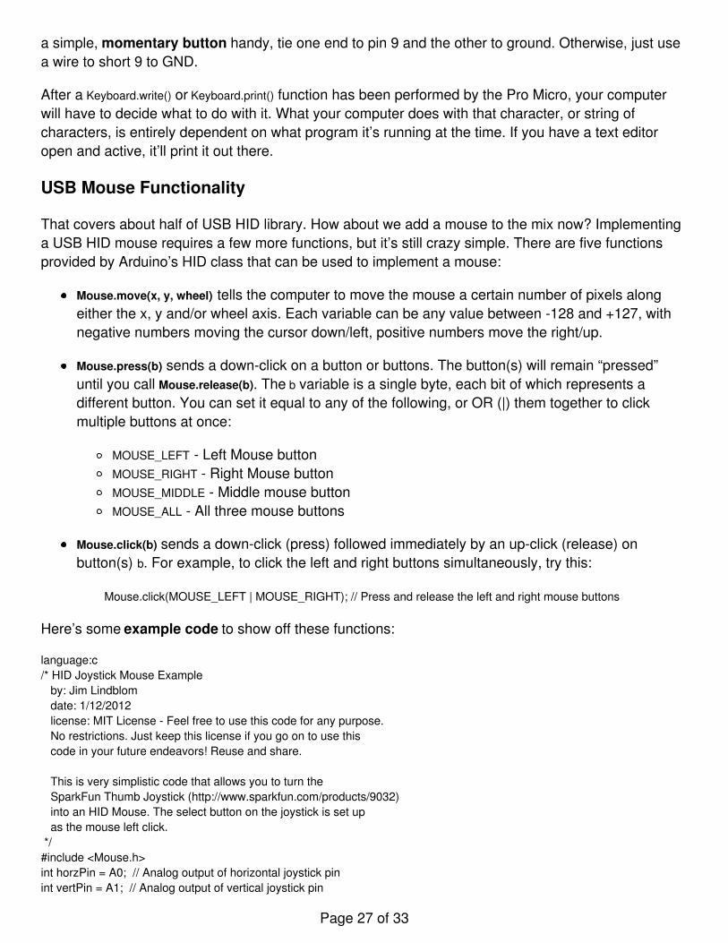
Here’s some example code to show off these functions:
language:c/* HID Joystick Mouse Example by: Jim Lindblom date: 1/12/2012 license: MIT License - Feel free to use this code for any purpose. No restrictions. Just keep this license if you go on to use this code in your future endeavors! Reuse and share.
This is very simplistic code that allows you to turn the SparkFun Thumb Joystick (http://www.sparkfun.com/products/9032) into an HID Mouse. The select button on the joystick is set up as the mouse left click. */#include <Mouse.h>int horzPin = A0; // Analog output of horizontal joystick pinint vertPin = A1; // Analog output of vertical joystick pin
Page 27 of 33
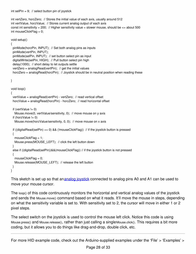
int selPin = 9; // select button pin of joystick
int vertZero, horzZero; // Stores the initial value of each axis, usually around 512int vertValue, horzValue; // Stores current analog output of each axisconst int sensitivity = 200; // Higher sensitivity value = slower mouse, should be <= about 500int mouseClickFlag = 0;
void setup(){ pinMode(horzPin, INPUT); // Set both analog pins as inputs pinMode(vertPin, INPUT); pinMode(selPin, INPUT); // set button select pin as input digitalWrite(selPin, HIGH); // Pull button select pin high delay(1000); // short delay to let outputs settle vertZero = analogRead(vertPin); // get the initial values horzZero = analogRead(horzPin); // Joystick should be in neutral position when reading these
}
void loop(){ vertValue = analogRead(vertPin) - vertZero; // read vertical offset horzValue = analogRead(horzPin) - horzZero; // read horizontal offset
if (vertValue != 0) Mouse.move(0, vertValue/sensitivity, 0); // move mouse on y axis if (horzValue != 0) Mouse.move(horzValue/sensitivity, 0, 0); // move mouse on x axis
if ((digitalRead(selPin) == 0) && (!mouseClickFlag)) // if the joystick button is pressed { mouseClickFlag = 1; Mouse.press(MOUSE_LEFT); // click the left button down } else if ((digitalRead(selPin))&&(mouseClickFlag)) // if the joystick button is not pressed { mouseClickFlag = 0; Mouse.release(MOUSE_LEFT); // release the left button }}
This sketch is set up so that an analog joystick connected to analog pins A0 and A1 can be used tomove your mouse cursor.
The loop() of this code continuously monitors the horizontal and vertical analog values of the joystickand sends the Mouse.move() command based on what it reads. It’ll move the mouse in steps, dependingon what the sensitivity variable is set to. With sensitivity set to 2, the cursor will move in either 1 or 2pixel steps.
The select switch on the joystick is used to control the mouse left click. Notice this code is usingMouse.press() and Mouse.release(), rather than just calling a single Mouse.click(). This requires a bit morecoding, but it allows you to do things like drag-and-drop, double click, etc.
For more HID example code, check out the Arduino-supplied examples under the ‘File’ > ‘Examples’ >
Page 28 of 33
‘09.USB’ menu.
Troubleshooting and FAQ
On this page you’ll find troubleshooting tips and FAQs. Here’s a directory of the subjects covered:
TroubleshootingSerial Port Not Showing Up in “Tools > Board” menuHow to Reset to BootloaderHow to Revive a “Bricked” Pro Micro
Frequently Asked QuestionsWhat are VIDs and PIDs?How Can I Change the VID and PID on an ATmega32U4?Why Does my ATmega32U4 Board Show up Twice in the Device Manager?How Does the IDE Know Which COM Port to Use?How Do I Reinstall the Bootloader?
Serial Port Not Showing Up in ‘Tools > Board’ Menu
The Pro Micro can be a finicky little thing. There are a few series of events that can lead to its serialport being removed from the Arduino IDE’s Serial Port selection menu. If you can’t see your ProMicro’s serial port, give these steps a try:
1. Close all Arduino windows. (Don’t forget to save!)2. Unplug Pro Micro from your computer.3. Wait a few seconds for the device to be detached.4. Plug Pro Micro back in.5. Open Arduino back up, check the Serial Ports menu again.
Reset to Bootloader
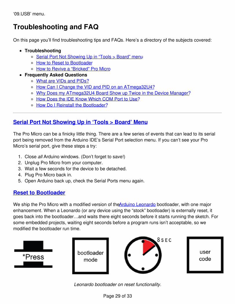
We ship the Pro Micro with a modified version of the Arduino Leonardo bootloader, with one majorenhancement. When a Leonardo (or any device using the “stock” bootloader) is externally reset, itgoes back into the bootloader…and waits there eight seconds before it starts running the sketch. Forsome embedded projects, waiting eight seconds before a program runs isn’t acceptable, so wemodified the bootloader run time.
Leonardo bootloader on reset functionality.
Page 29 of 33
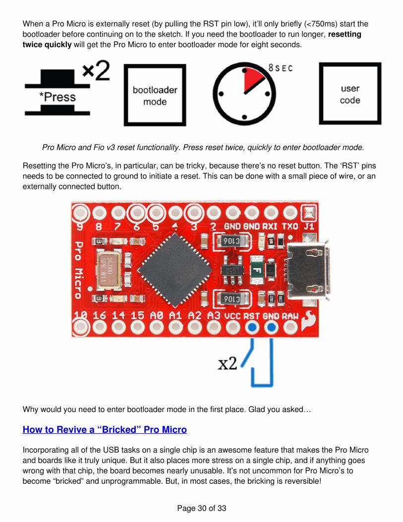
When a Pro Micro is externally reset (by pulling the RST pin low), it’ll only briefly (<750ms) start thebootloader before continuing on to the sketch. If you need the bootloader to run longer, resettingtwice quickly will get the Pro Micro to enter bootloader mode for eight seconds.
Pro Micro and Fio v3 reset functionality. Press reset twice, quickly to enter bootloader mode.
Resetting the Pro Micro’s, in particular, can be tricky, because there’s no reset button. The ‘RST’ pinsneeds to be connected to ground to initiate a reset. This can be done with a small piece of wire, or anexternally connected button.
Why would you need to enter bootloader mode in the first place. Glad you asked…
How to Revive a “Bricked” Pro Micro
Incorporating all of the USB tasks on a single chip is an awesome feature that makes the Pro Microand boards like it truly unique. But it also places more stress on a single chip, and if anything goeswrong with that chip, the board becomes nearly unusable. It’s not uncommon for Pro Micro’s tobecome “bricked” and unprogrammable. But, in most cases, the bricking is reversible!
Page 30 of 33
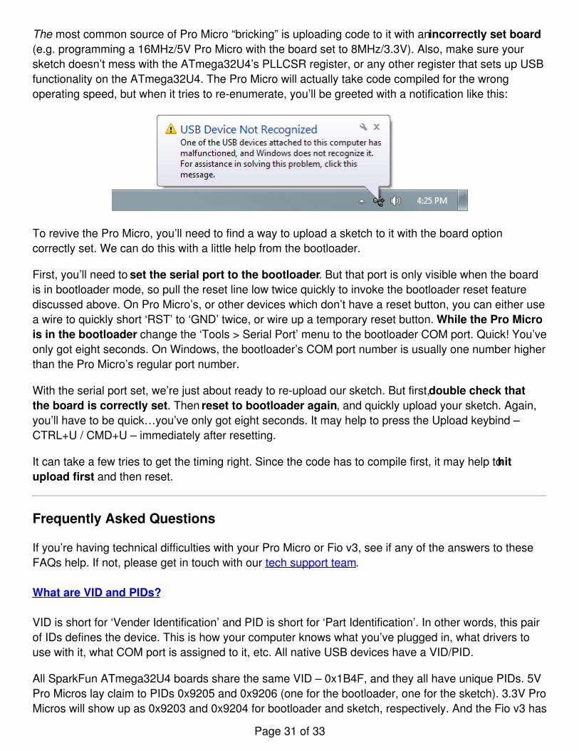
The most common source of Pro Micro “bricking” is uploading code to it with an incorrectly set board(e.g. programming a 16MHz/5V Pro Micro with the board set to 8MHz/3.3V). Also, make sure yoursketch doesn’t mess with the ATmega32U4’s PLLCSR register, or any other register that sets up USBfunctionality on the ATmega32U4. The Pro Micro will actually take code compiled for the wrongoperating speed, but when it tries to re-enumerate, you’ll be greeted with a notification like this:
To revive the Pro Micro, you’ll need to find a way to upload a sketch to it with the board optioncorrectly set. We can do this with a little help from the bootloader.
First, you’ll need to set the serial port to the bootloader. But that port is only visible when the boardis in bootloader mode, so pull the reset line low twice quickly to invoke the bootloader reset featurediscussed above. On Pro Micro’s, or other devices which don’t have a reset button, you can either usea wire to quickly short ‘RST’ to ‘GND’ twice, or wire up a temporary reset button. While the Pro Microis in the bootloader change the ‘Tools > Serial Port’ menu to the bootloader COM port. Quick! You’veonly got eight seconds. On Windows, the bootloader’s COM port number is usually one number higherthan the Pro Micro’s regular port number.
With the serial port set, we’re just about ready to re-upload our sketch. But first, double check thatthe board is correctly set. Then reset to bootloader again, and quickly upload your sketch. Again,you’ll have to be quick…you’ve only got eight seconds. It may help to press the Upload keybind –CTRL+U / CMD+U – immediately after resetting.
It can take a few tries to get the timing right. Since the code has to compile first, it may help to hitupload first and then reset.
Frequently Asked Questions
If you’re having technical difficulties with your Pro Micro or Fio v3, see if any of the answers to theseFAQs help. If not, please get in touch with our tech support team.
What are VID and PIDs?
VID is short for ‘Vender Identification’ and PID is short for ‘Part Identification’. In other words, this pairof IDs defines the device. This is how your computer knows what you’ve plugged in, what drivers touse with it, what COM port is assigned to it, etc. All native USB devices have a VID/PID.
All SparkFun ATmega32U4 boards share the same VID – 0x1B4F, and they all have unique PIDs. 5VPro Micros lay claim to PIDs 0x9205 and 0x9206 (one for the bootloader, one for the sketch). 3.3V ProMicros will show up as 0x9203 and 0x9204 for bootloader and sketch, respectively. And the Fio v3 has
Page 31 of 33

0xF100 and 0xF101.
How Can I Change the VID and PID on an ATMega32U4 Board?
Every time you upload code the VID and PID are uploaded to the device. These values are located inthe ‘boards.txt’ file and will therefore be determined by the board you have selected. Keep in mind thatif you select the wrong board you will get the wrong VID/PID uploaded which means the computercan’t recognize, and program the board. The VID/PID for the bootloader is part of the bootloader file.To change this you will need to recompile the bootloader with the new VID/PID, and upload it.
Why Does my ATMega32U4 Board Show up Twice in Device Manager?
Both the bootloader and the sketch have their own VID/PIDs. When you plug in a board thebootloader starts running for a few seconds, and you will see the board show up in Device Managerbased on those VID/PIDs. After a few seconds, the sketch will start running, and you will see DeviceManager disconnect from the bootloader and connect to the sketch.
How Does the IDE Know Which COM Port to Use?
When the IDE resets the board, the COM port is disconnected from the computer. The IDE then looksfor a new COM port. This is the port it uses. This is one of those weird things Arduino did to get thingsto work on this chip.
How Do I Reinstall the Bootloader?
Check out or reinstalling the bootloader tutorial, which should work for both ATMega32U4 andATMega328 boards. If you have the tools to do so, reinstalling the bootloader is often easier thentrying to stay in the bootloader. Since reinstalling the bootloader puts the board back in factorysettings this will reset the VID/PID numbers allowing your board to work again.
Resources and Going Further
Thanks for checking out our Pro Micro and Fio v3 Hookup Guide! If you’re looking for more resourcesrelated to these boards, here are some links:
SparkFun Pro MicroPro Micro Schematic (PDF)Pro Micro EAGLE Files (ZIP)Product GitHub Repo5V/16MHz Graphical Datasheet (PDF)3.3V/8MHz Graphical Datasheet (PDF)
SparkFun FioV3Schematic (PDF)EAGLE Files (ZIP)MCP73831 Charge IC Datasheet (PDF)Product GitHub Repo
Page 32 of 33
ATmega32u4 Firmware Notes (PDF)ATmega32U4 Datasheet (PDF)ATmega32U4 Arduino Addon GitHub Repository (RETIRED)SparkFun Arduino Board Addon GitHub Repository
Thanks for reading along with our Pro Micro hookup guide! Hopefully now you’re fully prepared tobegin using the Pro Micro in a project of your own. Here are some tutorials that might be worthchecking out as you continue down the rabbit hole:
Connecting Arduino to Processing
Send serial data from Arduino to Processing and back - even at the same time!Favorited Favorite 29
LilyPad ProtoSnap Plus Hookup Guide
The LilyPad ProtoSnap Plus is a sewable electronics prototyping board that you can use to learncircuits and programming with Arduino, then break apart to make an interactive fabric or wearableproject.Favorited Favorite 1
Tech Prank: Hardware Mouse Jiggler
Create an innocuous-looking USB stick with an Arduino Pro Micro and a 3D printed case that movesyour mouse pointer randomly every few seconds. Sure to anger your coworkers and friends!Favorited Favorite 3
learn.sparkfun.com | CC BY-SA 3.0 | SparkFun Electronics | Niwot, Colorado
Page 33 of 33