Embed Size (px)
Citation preview

Profi le rail guides
LLR
The SKF® brand now stands for more
than ever before, and means more to
you as a valued customer.
While SKF maintains its leadership
as the hallmark of quality bearings
throughout the world, new dimensions
in technical advances, product support
and services have evolved SKF into
a truly solutions-oriented supplier,
creating greater value for customers.
These solutions encompass ways to
bring greater productivity to customers,
not only with breakthrough application-
specific products, but also through
leading-edge design simulation tools
and consultancy services, plant asset
efficiency maintenance programmes,
and the industry’s most advanced
supply management techniques.
The SKF brand still stands for the very
best in rolling bearings, but it now
stands for much more.
SKF – the knowledge engineering
company
General information
3 Introduction
4 Product overview
6 Technical data
6 Preload classes
6 Speed
6 Acceleration
6 Temperature
7 Friction
7 Seals
7 Scraper plates
8 Load rating
8 Definition of the basic dynamic load rating
8 Definition of the basic static load rating
8 Definition and calculation of the basic rating life
8 Dynamic equivalent bearing load for calculation of the service life
9 Dynamic equivalent bearing load
9 Static equivalent bearing load
Accuracy
10 Accuracy classes
11 Selection criteria for combination of accuracy classes
12 Preloading and stiffness
Carriages
14 Load ratings - Quick selection
18 Accuracy classes, dimensions and designations
Standard rails
35 Product overview
36 Accuracy classes, dimensions and designations
Ordering key
40 Ordering key
Accessories
43 Product overview
44 Standard carriages
44 Scraper plates
45 Seals
46 Lubrication
48 Bellows
50 Cover strip
Mounting instructions
54 General mounting instructions
Maintenance and lubrications
62 Maintenance and lubrications
Content
3
General
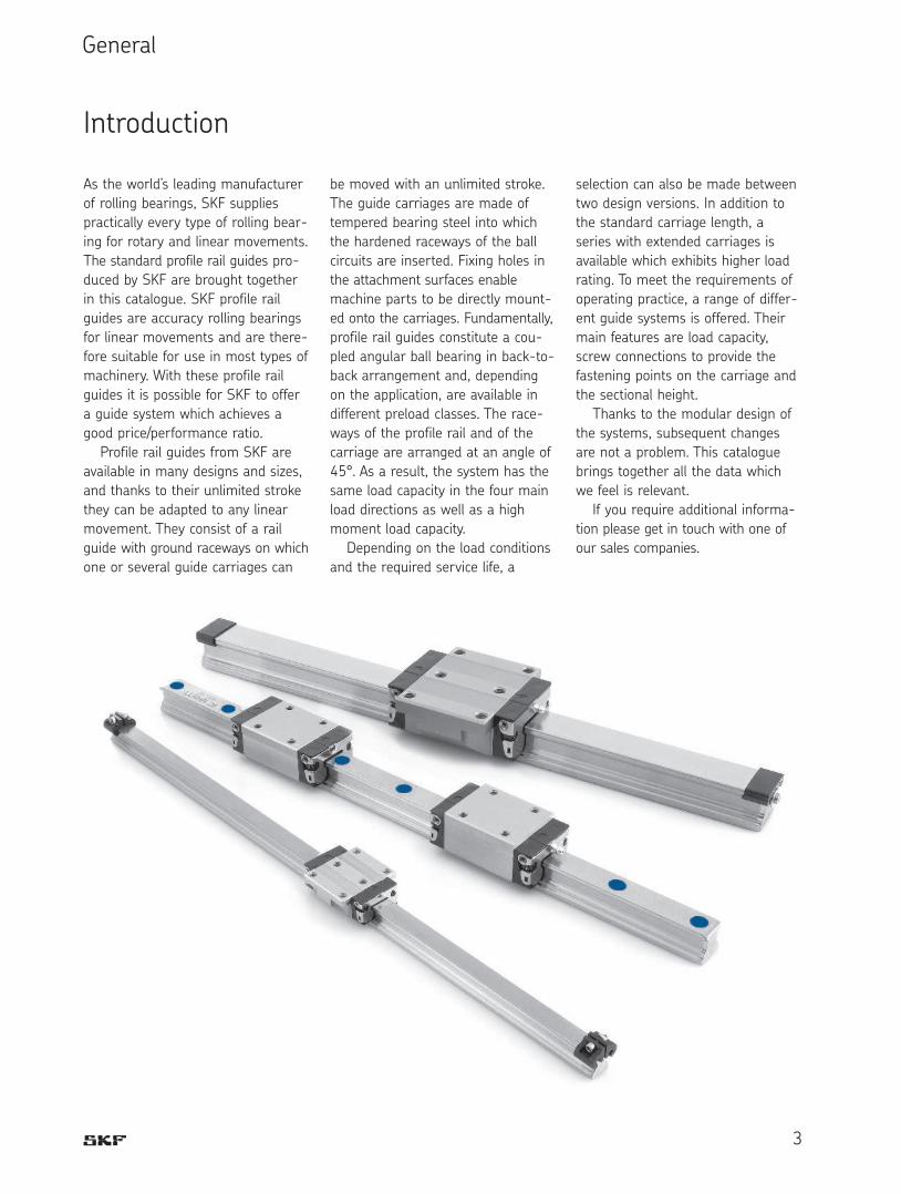
As the world’s leading manufacturer
of rolling bearings, SKF supplies
practically every type of rolling bear-
ing for rotary and linear movements.
The standard profile rail guides pro-
duced by SKF are brought together
in this catalogue. SKF profile rail
guides are accuracy rolling bearings
for linear movements and are there-
fore suitable for use in most types of
machinery. With these profile rail
guides it is possible for SKF to offer
a guide system which achieves a
good price/performance ratio.
Profile rail guides from SKF are
available in many designs and sizes,
and thanks to their unlimited stroke
they can be adapted to any linear
movement. They consist of a rail
guide with ground raceways on which
one or several guide carriages can
selection can also be made between
two design versions. In addition to
the standard carriage length, a
series with extended carriages is
available which exhibits higher load
rating. To meet the requirements of
operating practice, a range of differ-
ent guide systems is offered. Their
main features are load capacity,
screw connections to provide the
fastening points on the carriage and
the sectional height.
Thanks to the modular design of
the systems, subsequent changes
are not a problem. This catalogue
brings together all the data which
we feel is relevant.
If you require additional informa-
tion please get in touch with one of
our sales companies.
be moved with an unlimited stroke.
The guide carriages are made of
tempered bearing steel into which
the hardened raceways of the ball
circuits are inserted. Fixing holes in
the attachment surfaces enable
machine parts to be directly mount-
ed onto the carriages. Fundamentally,
profile rail guides constitute a cou-
pled angular ball bearing in back-to-
back arrangement and, depending
on the application, are available in
different preload classes. The race-
ways of the profile rail and of the
carriage are arranged at an angle of
45°. As a result, the system has the
same load capacity in the four main
load directions as well as a high
moment load capacity.
Depending on the load conditions
and the required service life, a
Introduction

4
• Carriages with and without
ball chain
• High load capacities in all main
directions and high moment
load capacities
• High dynamic performances:
v = 5 m/s; amax = 500 m/s2
• Low noise and smooth, light
running due to optimised ball
recirculation and ideal ball
chain geometry
• Long term lubrication system
• Lube ports with metal threads
on all sides.
• Full interchangeability due to
standardised rail, with or
without rail seal cover strip,
for all carriage versions
• Both grease and oil lubrication
possible despite initial grease
application
• Wide range of accessories
• Worldwide SKF service network
• Both sides of the guide rail can be
used as reference edges
• Various accuracy and preload
classes
• Carriages can be screwed from
above or below, depending on
type.
• Improved stiffness under lift off
and side loading conditions when
additional mounting screws are
used for the holes in the centre of
the carriage
• Integrated all-round sealing
through front and longitudinal
seals
• Wide range of accessories
Product overview

5
LLRHC xx SA
Flange short. Standard height.LLRHC xx A
Flange normal. Standard height.
LLRHC xx LA
Flange long. Standard height.
LLRHC xx R
Slim line normal. High.Ball chain
Optimises noise level and running
behaviour
LLRHC xx LR
Slim line long. High.
LLRHC xx SU
Slim line short. Standard height.LLRHC xx LU
Slim line long. Standard height.
LLRHC xx U
Slim line normal. Standard height.

6
General informationThe general technical data applies to
all rail guides (all carriages and
rails).
Special technical data is listed
separately for the individual designs.
Preload classesIn view of the different user require-
ments, the ball rail guides can be
supplied in four different preload
classes.
So as not to reduce the service
life, the preload should not amount
to more than 1/3 of the bearing
load F.
In general, the stiffness of the
carriage increases according to the
preload increase.
Guide systems withparallel rails• In connection with the selected
preload class the permissible
deviation in parallelism of the
rails must also be taken into
account (see tables for the
various designs).
• For the installation of rail guides in
the accuracy class P5 we
recommend the version with
clearance T0 or the preload
class T1 in order to avoid
stresses owing to the
tolerances.
Speedvmax: 5 m/s
Accelerationamax: 500 m/s
2
Only in the case of preloaded systems.
In the case of non-preloaded sys-
tems: amax = 50 m/s2
Technical data
Temperature resistancetmax: 100 °C
This is a maximum value which is
only permissible for a short time. In
continuous operation a maximum
temperature of 80 °C must not be
exceeded.
1 Recirculation parts:
POM (PA6.6)
2 Lubrication nipple:
carbon steel
3 Metal front plates:
1.4301
4 Seals: TEE-E
5 Flange screws:
carbon steel
6 Thread pins: 1.4301
7 Balls: bearing steel
8 Housing: tempered steel
9 Cover strip retaining
clamps: aluminium
10 Clamping screw and nut:
1.4301
11 Rail: tempered steel
12 Cover strip: 1.4301
Material specifications
1
2
3
9
11
1012
45
6
7
8

7
FrictionThe friction coefficient µ of the ball
rail guide is approx. 0,002 to 0,003
(not including the friction of the seal).
As a result of the design with 4
ball rows a 2-point contact exists for
all load directions. This reduces fric-
tion to a minimum (Fig. 1).
Scraper platesScraper plates can be ordered as
accessories (have to be attached
by the customer).
They are suitable for use in most
environments where coarse dirt or
chips are encountered.
SealsSeals should prevent the penetration
of dirt and chips into the interior of
the carriage in order to avoid pre-
mature failure.
Universal seal
Universal seals are installed as stan-
dard in SKF carriages.
They have a constant sealing
effect on rails with and without
cover strip.
In addition to efficient sealing, the
design also provides for low friction.
For applications where low friction
is required light-contact seals are
available on request.
Front seal
Front seals can be ordered as acces-
sories and are attached by the cus-
tomer.
They are suitable for use in
environments with fine dust or
metal particles, as well as coolants
or cutting fluids.
Note!
For extreme duty in environments
with coarse dirt or metal particles,
or where there is massive use of
coolants or cutting fluids, Viton seals
are available on request.
Viton seals have to be attached
by the customer.
Fig. 1

Basic rating life at constant speed
The basic rating life L or Lh can be
calculated applying the formula (1),
(2) or (3):
Basic rating life at changing speed
(3)
(4)
L10 = basic rating life (m)
L10h = basic rating life (h)
C = basic dynamic load
rating (N)
P = equivalent load (N)
s = stroke length (m)
n = stroke frequency
(double strokes/min)
vm = mean speed (m/min)
v1,v2...vn = travel speeds (m/min)
t1,t2...tn = time proportions for
v1, v2...vn (%)
The formulae for calculating the
service life of profile rail guides
apply to a stroke length of S ≥ 2
times the carriage length. At lower
values the load rating is reduced.
Please consult SKF.
C P
L10 = ( )3 105
Dynamic equivalentbearing load for calcu-lation of the service life
For a fluctuating bearing load the
dynamic equivalent loading F is cal-
culated according to formula (5):
Fm = constant mean
load (N)
F1, F2 . . . Fn = constant loads
during stroke
lengths s1, + s2 +,
....sn (N)
s = total stroke
length (s = s1 +
s2 +, ....+ sn),
during which
loads F1, F2 ... Fnhave an effect (mm)
• given a combined bearing load
3
8
Definition of the basicdynamic load rating CThe radial load, constant in magni-
tude and direction, which a linear
rolling bearing can in theory accom-
modate for a basic rating life repre-
sented by a travelled distance of
105 m (to DIN 636 Part 1).
The basic dynamic load ratings in
the tables are generally 30 % higher
than the values to DIN. They have
been verified in tests.
Definition of the basicstatic load rating C0The static load in the direction of
loading which corresponds to a cal-
culated load in the centre of the
most highly loaded contact point
between the rolling element and both
raceways (rail) at an osculation of
≤ 0,52, 4 200 MPa.
Note:
At this load on the contact point a
permanent total deformation of the
rolling element and raceway occurs
which corresponds to about 0,0001
times the rolling element diameter
(to DIN 636 Part 2).
Definition and calcula-tion of the basic ratinglifeThe calculated life achievable with
90 % reliability for a single rolling
bearing or a group of evidently
identical rolling bearings running
under identical conditions given the
material generally used today of
normal manufacturer’s quality and
usual operating conditions (to DIN
636 Part 1).
L10h= L10
2 ¥ s ¥ n ¥ 60
(1)
(2)
L10h = L10
60 ¥ vm
Fm= F13¥ s1+ F2
3¥ s2+ ... + Fn3¥ sn
s
vm =t1 ¥ v1 + t2 ¥ v2 + ... + tn ¥ vn
100
(5)
Load rating
Note on dynamic loadcapacities and momentsDetermination of dynamic load
capacities and moments is based on
a travel life of 100 000 m. However,
frequently this is determined on the
basis of only 50 000 m. In this case
for comparison: multiply values C, MC
and MA by 1.26 in accordance with
SKF tables.
For carriages with ball chain the
permissible moments are reduced in
accordance with the load ratings.
9
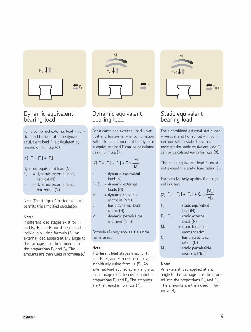
Dynamic equivalentbearing load
For a combined external load – ver-
tical and horizontal – in combination
with a torsional moment the dynam-
ic equivalent load F can be calculated
using formula (7):
(7)
F = dynamic equivalent
load (N)
FV, FH = dynamic external
loads (N)
M = dynamic torsional
moment (Nm)
C = basic dynamic load
rating (N)
Mt = dynamic permissible
moment (Nm)
Formula (7) only applies if a single
rail is used.
Note:
If different load stages exist for FVand FH, FV and FH must be calculated
individually using formula (5). An
external load applied at any angle to
the carriage must be divided into the
proportions FV and FH The amounts
are then used in formula (7).
F = |FV| + |FH|
FV
FH
F = |FV| + |FH| + C ¥|M|
Mt
FV
FH
M
FV0
M
FH0
F0 = |FV0| + |FH0| + C0 ¥|M0|
Mt0
Static equivalentbearing load
For a combined external static load
– vertical and horizontal – in con-
nection with a static torsional
moment the static equivalent load F0can be calculated using formula (8).
The static equivalent load F0 must
not exceed the static load rating C0.
Formula (8) only applies if a single
rail is used.
(8)
F0 = static equivalent
load (N)
FV0, FH0 = static external
loads (N)
M0 = static torsional
moment (Nm)
C0 = basic static load
rating (N)
Mt0 = static permissible
moment (Nm)
Note:
An external load applied at any
angle to the carriage must be divid-
ed into the proportions FV0 and FH0.
The amounts are then used in for-
mula (8).
Dynamic equivalentbearing load
For a combined external load – ver-
tical and horizontal – the dynamic
equivalent load F is calculated by
means of formula (6):
(6)
dynamic equivalent load (N)
FV = dynamic external load,
vertical (N)
FH = dynamic external load,
horizontal (N)
Note: The design of the ball rail guide
permits this simplified calculation.
Note:
If different load stages exist for FVand FH, FV and FH must be calculated
individually using formula (5). An
external load applied at any angle to
the carriage must be divided into
the proportions FV and FH. The
amounts are then used in formula (6)

10
Accuracy classes andtheir tolerancesSKF profile rail guides are available
in five accuracy classes. As shown in
the adjacent illustration, the toler-
ances are defined for each accuracy
class. The stated accuracy classes
are available for almost all types of
profile rail guides. For the designs
which can be supplied please refer
to the respective table on page 11.
Dimensional tolerance in height “H”
The dimensional tolerance in height
“H” is the maximum deviation of the
height “H” for the carriages on a
profile rail (Fig. 2).
Dimensional tolerance in width “N”
The dimensional tolerance in width
“N” is the maximum deviation of the
“N” dimension for the carriages on a
profile rail (Fig. 2).
• The “N” dimension designates the
distance of the mounting surface
of the profile rail from the ground
side surface of the carriage.
• The accuracies stated are mean
values and relate to the centre of
the carriage.
• The tolerances should be checked
again after the profile rail guide
has been mounted on the machine
bed.
For example, a carriage can be
used without any problems on dif-
ferent rails of the same size.
Conversely, various carriages can
be used on one rail.
Problem-free inter-changeability throughprecision manufactureThe rail and carriage are produced
so precisely by SKF, especially in the
ball raceway area, that each individ-
ual element can be exchanged at
any time.
Accuracy
Accuracy classes
Fig. 3Fig. 2
Fig. 1
Accuracy class Tolerance Max. differences in dimension
H and N on one rail
H (µm) N (µm) D H (µm) D N (µm)
P5 ± 100 ± 40 30 30
P3 ±40 ±20 15 15
P1 ±20 ±10 7 7
P01 ±10 ±7 5 5
P001 ±5 ±5 3 3
Measured in
the centre of
the carriage:
For any combination
of carriages and rails
over the entire rail
length
For different carriages at
the same rail position
P1Deviation in parallelism (µm)
L (rail length, mm)
* Tolerances for the combination of different accuracy classes in respect
of carriage and rail can be referred to on page 11.

11
Running accuracy asselection criterion
By means of perfected ball entry
and exit zones in the carriages of
accuracy classes P1 and P001, a
hitherto unattained running accuracy
accompanied by extremely low pul-
sation is achieved.
This is particularly suitable for
ultra-fine metal cutting operations,
metrology, high-precision scanners,
erosion techniques etc.
Recommendations forthe combination ofaccuracy classesRecommended for short strokes and
small distances between the car-
riages:
Carriage in higher accuracy class
than guide rail.
Recommended for long strokes
and larger distances between the
carriages:
Guide rail in higher accuracy class
than carriage.
Selection criteria for combination of accuracy classes
Rails P5 P3 P1 P01 P001
Carriages µm µm µm µm µm
Tolerance dimension H (µm) ± 100 ± 48 ± 32 ± 23 ± 19
P5 Tolerance dimension N (µm) ± 40 ± 28 ± 22 ± 20 ± 19
Max. difference of dimensions H and N on a rail (µm) 30 30 30 30 30
Tolerance dimension H (µm) ± 88 ± 40 ± 23 ± 23 ± 19
P3 Tolerance dimension N (µm) ± 33 ± 20 ± 14 ± 20 ± 19
Max. difference of dimensions H and N on a rail (µm) 15 15 15 15 15
Tolerance dimension H (µm) ± 84 ± 34 ± 21 ± 11 ± 7
P1 Tolerance dimension N (µm) ± 28 ± 16 ± 10 ± 8 ± 7
Max. difference of dimensions H and N on a rail (µm) 7 7 7 7 7
Tolerance dimension H (µm) ± 83 ± 33 ± 19 ± 10 ± 6
P01 Tolerance dimension N (µm) ± 27 ± 15 ± 9 ± 7 ± 6
Max. difference of dimensions H and N on a rail (µm) 5 5 5 5 5
Tolerance dimension H (µm) ± 82 ± 32 ± 18 ± 9 ± 5
P001 Tolerance dimension N (µm) ± 26 ± 14 ± 8 ± 6 ± 5
Max. difference of dimensions H and N on a rail (µm) 3 3 3 3 3

12
For perfect operating behaviour
under various operating conditions
in an extremely wide range of appli-
cations it is necessary to establish
the suitable preload. In general, a
slight to medium preload is enough
for the majority of applications. For
special applications in which high
shock loads and vibration can occur
it is advisable to use a higher pre-
loading. The preload classes offered
by SKF are categorised in Table 4.
Selection of the preload classIn the designs with clearance no
preloading is achieved. Instead, there
is clearance of between 1 and 10
µm between the carriage and rail. If
two rails and more than one car-
riage per rail are used this clearance
is in most cases equalised by paral-
lelism tolerances.
Preload force referred to the basic
dynamic load rating Cdyn of the
respective carriage.
Example:
Carriage LLRHC 35 A
C = 41 900 N
Preload 0,02 x C = 838 N
This carriage is preloaded with a
basic load of approx. 838N.
Preloading and stiffness
Versions and area of applications
T0 – Clearance
For particularly smooth-running guide systems with low fric-
tion and low external influences. Designs with clearance are
only available in the accuracy classes P5 and P3.
T1 - Preload 0,02 C
For precise guide systems with low external load and high
requirements in respect of overall stiffness.
T2 - Preload 0,08 C
For precise guide systems with high external load and high
requirements in respect of overall stiffness; also recommended
for single-rail systems. Above-average moment loads are
absorbed without any significant elastic deformation. At only
medium moment loads the overall stiffness is further
improved.
T3 - Preload 0,13 C
For highly rigid guide systems such as precision machine tools
or injection mould clamping units. Above-average loads and
moments are absorbed with lowest-possible elastic deforma-
tion. Version with preload T3 only available in accuracy classes
P1, P01 and P001.
Table 4

13
Deflection as a function of
preload class and carriage
Example:
Carriage LLRHC 35 A,
a) Preload 0,02 C (T1)
b) Preload 0,08 C (T2)
c) Preload 0,13 C (T3)
Example:
Carriage LLRHC 35 LA,
a) Preload 0,02 C (T1)
b) Preload 0,08 C (T2)
c) Preload 0,13 C (T3)
Example:
Carriage LLRHC 35 U,
a) Preload 0,02 C (T1)
b) Preload 0,08 C (T2)
c) Preload 0,13 C (T3)
Example:
Carriage LLRHC 35 LU,
a) Preload 0,02 C (T1)
b) Preload 0,08 C (T2)
c) Preload 0,13 C (T3)
Legend
del. = elastic deformation
F = load
0 5 000 10 000 15 000 20 000 25 000
0 5 000 10 000 15 000 20 000 25 000
0 5 000 10 000 15 000 20 000 25 000
0 5 000 10 000 15 000 20 000 25 000

14
Carriages
Load ratings
Size 15 20 25 30 35 45Design
ball chain C (N) 5 900 12 400 14 000 22 100 29 300 –no ball chain C (N) 6 800 12 400 15 800 22 100 29 300 –
ball chain C0 (N) 6 700 13 600 15 200 24 800 32 400 –no ball chain C0 (N) 8 100 13 600 18 200 24 800 32 400 –
LLRHC xx SA (Flange short. Standard height.)
LLRHC xx A (Flange normal. Standard height.)
LLRHC xx LA (Flange long. Standard height.)
Size 15 20 25 30 35 45Design
ball chain C (N) 7 280 17 400 21 300 29 300 41 900 63 300no ball chain C (N) 7 800 18 800 22 800 31 700 41 900 68 100
ball chain C0 (N) 12 100 21 700 27 300 37 200 54 000 77 100no ball chain C0 (N) 13 500 24 400 30 400 41 300 54 000 85 700
Size 15 20 25 30 35 45Design
ball chain C (N) 9 000 23 100 27 500 38 000 53 000 81 900no ball chain C (N) 10 000 24 400 30 400 40 000 55 600 90 400
ball chain C0 (N) 17 500 32 500 39 500 53 700 75 600 111 400no ball chain C0 (N) 20 200 35 200 45 500 57 800 81 000 128 500
15
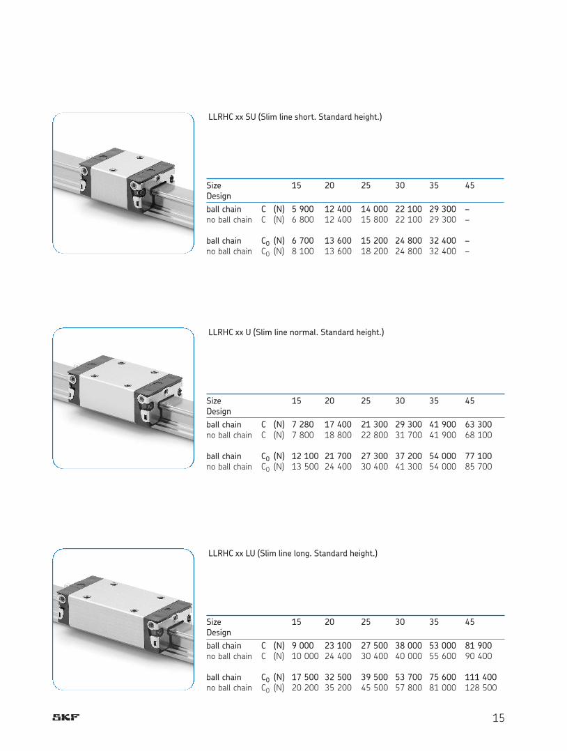
LLRHC xx SU (Slim line short. Standard height.)
Size 15 20 25 30 35 45Design
ball chain C (N) 5 900 12 400 14 000 22 100 29 300 –no ball chain C (N) 6 800 12 400 15 800 22 100 29 300 –
ball chain C0 (N) 6 700 13 600 15 200 24 800 32 400 –no ball chain C0 (N) 8 100 13 600 18 200 24 800 32 400 –
LLRHC xx U (Slim line normal. Standard height.)
Size 15 20 25 30 35 45Design
ball chain C (N) 7 280 17 400 21 300 29 300 41 900 63 300no ball chain C (N) 7 800 18 800 22 800 31 700 41 900 68 100
ball chain C0 (N) 12 100 21 700 27 300 37 200 54 000 77 100no ball chain C0 (N) 13 500 24 400 30 400 41 300 54 000 85 700
LLRHC xx LU (Slim line long. Standard height.)
Size 15 20 25 30 35 45Design
ball chain C (N) 9 000 23 100 27 500 38 000 53 000 81 900no ball chain C (N) 10 000 24 400 30 400 40 000 55 600 90 400
ball chain C0 (N) 17 500 32 500 39 500 53 700 75 600 111 400no ball chain C0 (N) 20 200 35 200 45 500 57 800 81 000 128 500

16
LLRHC xx R (Slim line normal. High.)
Size 15 25 30 35 45Design
ball chain C (N) 7 280 21 300 29 300 41 900 63 300no ball chain C (N) 7 800 22 800 31 700 41 900 68 100
ball chain C0 (N) 12 100 27 300 37 200 54 000 77 100no ball chain C0 (N) 13 500 30 400 41 300 54 000 85 700
LLRHC xx LR (Slim line long. High.)
Size 25 30 35 45Design
ball chain C (N) 27 500 38 000 53 000 81 900no ball chain C (N) 30 400 40 000 55 600 90 400
ball chain C0 (N) 39 500 53 700 75 600 111 400no ball chain C0 (N) 45 500 57 800 81 000 128 500
Note on dynamic load capacities and moments
Determination of dynamic load capacities and moments is based on a travel life of
100 000 m. However, frequently this is determined on the basis of only 50 000 m.
In this case for comparison: multiply values C, MC and MA by 1.26 in accordance with
SKF tables.
For carriages with ball chain the permissible moments are reduced in accordance with
the load ratings.

17
Notes

18
Carriage LLRHC xx SA
Flange short. Standard height.
For type designation see
designation system
Dynamic values
Speed vmax = 5 m/s
Acceleration amax = 500 m/s2
Size Accuracy class Type designation incl. preload class
T0 T1
15 P5 LLRHC 15 SA T0 P5 LLRHC 15 SA T1 P5
P3 LLRHC 15 SA T0 P3 LLRHC 15 SA T1 P3
20 P5 LLRHC 20 SA T0 P5 LLRHC 20 SA T1 P5
P3 LLRHC 20 SA T0 P3 LLRHC 20 SA T1 P3
25 P5 LLRHC 25 SA T0 P5 LLRHC 25 SA T1 P5
P3 LLRHC 25 SA T0 P3 LLRHC 25 SA T1 P3
30 P5 LLRHC 30 SA T0 P5 LLRHC 30 SA T1 P5
P3 LLRHC 30 SA T0 P3 LLRHC 30 SA T1 P3
35 P5 LLRHC 35 SA T0 P5 LLRHC 35 SA T1 P5
P3 LLRHC 35 SA T0 P3 LLRHC 35 SA T1 P3
Accuracy classes, dimensions and designations

19
Size Dimensions (mm) Weight
C C0 MC MC0 MA MB
N1 H7±0,5 d4 S2 d3 M2 (kg) dyn. stat. dyn. stat. dyn. stat.
15 5,2 10,3 4,3 M5 4,4 M2,5-3,5 depth 0,15 5 400 8 100 52 80 19 28
20 7,7 13,2 5,3 M6 6,0 M3-5 depth 0,30 12 400 13 600 150 170 52 58
25 9,3 15,2 6,7 M8 7,0 M3-5 depth 0,50 15 900 18 200 230 260 82 94
30 11,0 17,0 8,5 M10 9,0 M3-5 depth 0,80 22 100 24 800 380 430 133 150
35 12,0 20,5 8,5 M10 9,0 M3-5 depth 1,20 29 300 32 400 640 700 200 220
Size Dimensions (mm)
W1 A1 W N L1 L2 H H1 H41) H4
2) H3 W2 W3 H5 L6 L4 H8 H915 47 23,5 15 16,0 44,7 25,7 24 19,90 16,30 16,20 5,0 38 24,55 6,70 16,25 17,85 3,20 3,20
20 63 31,5 20 21,5 57,3 31,9 30 25,35 20,75 20,55 6,0 53 32,50 7,30 22,95 22,95 3,35 3,35
25 70 35,0 23 23,5 67,0 38,6 36 29,90 24,45 24,25 7,5 57 38,30 11,50 25,35 26,50 5,50 5,50
30 90 45,0 28 31,0 75,3 45,0 42 35,35 28,55 28,35 7,0 72 48,40 14,60 28,80 30,50 6,05 6,05
35 100 50,0 34 33,0 84,9 51,4 48 40,40 32,15 31,85 8,0 82 58,00 17,35 32,70 34,20 6,90 6,90 1)
1) Dimension H4 with cover strip.2) Dimension H4 without cover strip
a) For O-ringSize 15: † 4 x 1,0 (mm)Size 20-35: † 5 x 1,0 (mm)Open lubrication hole as required.See additional elements: Mounting of lubrication adapter.
b) Lubrication nipple size 15 and 20: Funnel-type nippleType A – Thread size M3 x 5, DIN 3405B2 = 1,6 mmWhen using other nipples, the max. permissible screw depth of 5 mm must be observed!Size 25 to 35: M6 x 8, DIN 71412B2 = 9,5 mm When using other nipples, the max. permissible screw depth of 8 mm must be observed! Lubrication nipple supplied along with the rail guide (unmounted).Connection possible at all sides.If pin holes are needed, please refer to section "Mounting instructions".
Load ratings (N) Moments (Nm)

20
Carriage LLRHC xx A
Flange normal. Standard height.
For type designation see
designation system
Dynamic values
Speed vmax = 5 m/s
Acceleration amax = 500 m/s2
Size Accuracy class Type designation incl. preload classT0 T1 T2 T3
15 P5 LLRHC 15 A T0 P5 LLRHC 15 A T1 P5 LLRHC 15 A T2 P5
P3 LLRHC 15 A T0 P3 LLRHC 15 A T1 P3 LLRHC 15 A T2 P3
P1 LLRHC 15 A T1 P1 LLRHC 15 A T2 P1 LLRHC 15 A T3 P1
P01 LLRHC 15 A T1 P01 LLRHC 15 A T2 P01 LLRHC 15 A T3 P01
P001 LLRHC 15 A T1 P001 LLRHC 15 A T2 P001 LLRHC 15 A T3 P001
20 P5 LLRHC 20 A T0 P5 LLRHC 20 A T1 P5 LLRHC 20 A T2 P5
P3 LLRHC 20 A T0 P3 LLRHC 20 A T1 P3 LLRHC 20 A T2 P3
P1 LLRHC 20 A T1 P1 LLRHC 20 A T2 P1 LLRHC 20 A T3 P1
P01 LLRHC 20 A T1 P01 LLRHC 20 A T2 P01 LLRHC 20 A T3 P01
P001 LLRHC 20 A T1 P001 LLRHC 20 A T2 P001 LLRHC 20 A T3 P001
25 P5 LLRHC 25 A T0 P5 LLRHC 25 A T1 P5 LLRHC 25 A T2 P5
P3 LLRHC 25 A T0 P3 LLRHC 25 A T1 P3 LLRHC 25 A T2 P3
P1 LLRHC 25 A T1 P1 LLRHC 25 A T2 P1 LLRHC 25 A T3 P1
P01 LLRHC 25 A T1 P01 LLRHC 25 A T2 P01 LLRHC 25 A T3 P01
P001 LLRHC 25 A T1 P001 LLRHC 25 A T2 P001 LLRHC 25 A T3 P001
30 P5 LLRHC 30 A T0 P5 LLRHC 30 A T1 P5 LLRHC 30 A T2 P5
P3 LLRHC 30 A T0 P3 LLRHC 30 A T1 P3 LLRHC 30 A T2 P3
P1 LLRHC 30 A T1 P1 LLRHC 30 A T2 P1 LLRHC 30 A T3 P1
P01 LLRHC 30 A T1 P01 LLRHC 30 A T2 P01 LLRHC 30 A T3 P01
P001 LLRHC 30 A T1 P001 LLRHC 30 A T2 P001 LLRHC 30 A T3 P001
35 P5 LLRHC 35 A T0 P5 LLRHC 35 A T1 P5 LLRHC 35 A T2 P5
P3 LLRHC 35 A T0 P3 LLRHC 35 A T1 P3 LLRHC 35 A T2 P3
P1 LLRHC 35 A T1 P1 LLRHC 35 A T2 P1 LLRHC 35 A T3 P1
P01 LLRHC 35 A T1 P01 LLRHC 35 A T2 P01 LLRHC 35 A T3 P01
P001 LLRHC 35 A T1 P001 LLRHC 35 A T2 P001 LLRHC 35 A T3 P001
45 P5 LLRHC 45 A T0 P5 LLRHC 45 A T1 P5 LLRHC 45 A T2 P5
P3 LLRHC 45 A T0 P3 LLRHC 45 A T1 P3 LLRHC 45 A T2 P3
P1 LLRHC 45 A T1 P1 LLRHC 45 A T2 P1 LLRHC 45 A T3 P1
P01 LLRHC 45 A T1 P01 LLRHC 45 A T2 P01 LLRHC 45 A T3 P01
P001 LLRHC 45 A T1 P001 LLRHC 45 A T2 P001 LLRHC 45 A T3 P001
bold text = standard range

21
a) For O-ringSize 15: † 4 x 1,0 (mm)Size 20-45: † 5 x 1,0 (mm)Open lubrication hole as required.See additional elements: Mounting of lubrication adapter.
b) Recommended position for pin holes (dimensions W4, see “Mounting instructions”)NB: For production-related reasons there may be pilot drill holes in the middle of the carriage. They are suitable for drilling..
c) Lubrication nipple size 15 and 20: Funnel-type nippleType A – Thread size M3 x 5, DIN 3405B2 = 1,6 mm When using other nipples, the max. permissible screw depth of 5 mm must be observed!
Size 25 to 45: M6 x 8, DIN 71412B2 = 9,5 mm When using other lubrication nipples, the max. permissible screw depth of 8 mm must be observed! Lubrication nipple supplied with the rail guide (unmounted).Connection possible at all sides.
Size Dimensions (mm) Weight
C C0 MC MC0 MA MB
N1 W7±0,5 H7
±0,5 d4 S2 d3 M2 (kg) dyn. stat. dyn. stat. dyn. stat.
15 5,2 4,4 10,3 4,3 M5 4,4 M2,5-3,5 depth 0,20 7 800 13 500 74 130 40 71
20 7,7 5,2 13,2 5,3 M6 6,0 M3-5 depth 0,45 18 800 24 400 240 310 130 165
25 9,3 7,0 15,2 6,7 M8 7,0 M3-5 depth 0,65 22 800 30 400 320 430 180 240
30 11,0 7,9 17,0 8,5 M10 9,0 M3-5 depth 1,10 31 700 41 300 540 720 290 380
35 12,0 10,2 20,5 8,5 M10 9,0 M3-5 depth 1,60 41 900 54 000 890 1 160 440 565
45 15,0 14,4 23,5 10,4 M12 14,0 M4-7 depth 3,00 68 100 85 700 1 830 2 310 890 1 1303)
Size Dimensions (mm)
W1 A1 W N L1 L2 H H1 H41) H4
2) H3 W2 L3 L5 W3 H5 L6 L4 H8 H915 47 23,5 15 16,0 58,2 39,2 24 19,90 16,30 16,20 5,0 38 30 26 24,55 6,70 8,00 9,6 3,20 3,20
20 63 31,5 20 21,5 75,0 49,6 30 25,35 20,75 20,55 6,0 53 40 35 32,50 7,30 11,80 11,8 3,35 3,35
25 70 35,0 23 23,5 86,2 57,8 36 29,90 24,45 24,25 7,5 57 45 40 38,30 11,50 12,45 13,6 5,50 5,50
30 90 45,0 28 31,0 97,7 67,4 42 35,35 28,55 28,35 7,0 72 52 44 48,40 14,60 14,00 15,7 6,05 6,05
35 100 50,0 34 33,0 110,5 77,0 48 40,40 32,15 31,85 8,0 82 62 52 58,00 17,35 14,50 16,0 6,90 6,90
45 120 60 45 37,5 137,6 97,0 60 50,30 40,15 39,85 10,0 100 80 60 69,80 20,90 17,30 19,3 8,20 8,201) Dimension H4 with cover strip.
2) Dimension H4 without cover strip
Load ratings (N) Moments (Nm)

22
Carriage LLRHC xx LA
Flange long. Standard height.
For type designation see designation
system
Dynamic values
Speed vmax = 5 m/s
Acceleration amax = 500 m/s2
Size Accuracy class Type designation incl. preload classT0 T1 T2 T3
15 P5 LLRHC 15 LA T0 P5 LLRHC 15 LA T1 P5 LLRHC 15 LA T2 P5
P3 LLRHC 15 LA T0 P3 LLRHC 15 LA T1 P3 LLRHC 15 LA T2 P3
P1 LLRHC 15 LA T1 P1 LLRHC 15 LA T2 P1 LLRHC 15 LA T3 P1
P01 LLRHC 15 LA T1 P01 LLRHC 15 LA T2 P01 LLRHC 15 LA T3 P01
P001 LLRHC 15 LA T1 P001 LLRHC 15 LA T2 P001 LLRHC 15 LA T3 P001
20 P5 LLRHC 20 LA T0 P5 LLRHC 20 LA T1 P5 LLRHC 20 LA T2 P5
P3 LLRHC 20 LA T0 P3 LLRHC 20 LA T1 P3 LLRHC 20 LA T2 P3
P1 LLRHC 20 LA T1 P1 LLRHC 20 LA T2 P1 LLRHC 20 LA T3 P1
P01 LLRHC 20 LA T1 P01 LLRHC 20 LA T2 P01 LLRHC 20 LA T3 P01
P001 LLRHC 20 LA T1 P001 LLRHC 20 LA T2 P001 LLRHC 20 LA T3 P001
25 P5 LLRHC 25 LA T0 P5 LLRHC 25 LA T1 P5 LLRHC 25 LA T2 P5
P3 LLRHC 25 LA T0 P3 LLRHC 25 LA T1 P3 LLRHC 25 LA T2 P3
P1 LLRHC 25 LA T1 P1 LLRHC 25 LA T2 P1 LLRHC 25 LA T3 P1
P01 LLRHC 25 LA T1 P01 LLRHC 25 LA T2 P01 LLRHC 25 LA T3 P01
P001 LLRHC 25 LA T1 P001 LLRHC 25 LA T2 P001 LLRHC 25 LA T3 P001
30 P5 LLRHC 30 LA T0 P5 LLRHC 30 LA T1 P5 LLRHC 30 LA T2 P5
P3 LLRHC 30 LA T0 P3 LLRHC 30 LA T1 P3 LLRHC 30 LA T2 P3
P1 LLRHC 30 LA T1 P1 LLRHC 30 LA T2 P1 LLRHC 30 LA T3 P1
P01 LLRHC 30 LA T1 P01 LLRHC 30 LA T2 P01 LLRHC 30 LA T3 P01
P001 LLRHC 30 LA T1 P001 LLRHC 30 LA T2 P001 LLRHC 30 LA T3 P001
35 P5 LLRHC 35 LA T0 P5 LLRHC 35 LA T1 P5 LLRHC 35 LA T2 P5
P3 LLRHC 35 LA T0 P3 LLRHC 35 LA T1 P3 LLRHC 35 LA T2 P3
P1 LLRHC 35 LA T1 P1 LLRHC 35 LLA T2 P1 LLRHC 35 LA T3 P1
P01 LLRHC 35 LA T1 P01 LLRHC 35 LA T2 P01 LLRHC 35 LA T3 P01
P001 LLRHC 35 LA T1 P001 LLRHC 35 LA T2 P001 LLRHC 35 LA T3 P001
45 P5 LLRHC 45 LA T0 P5 LLRHC 45 LA T1 P5 LLRHC 45 LA T2 P5
P3 LLRHC 45 LA T0 P3 LLRHC 45 LA T1 P3 LLRHC 45 LA T2 P3
P1 LLRHC 45 LA T1 P1 LLRHC 45 LA T2 P1 LLRHC 45 LA T3 P1
P01 LLRHC 45 LA T1 P01 LLRHC 45 LA T2 P01 LLRHC 45 LA T3 P01
P001 LLRHC 45 LA T1 P001 LLRHC 45 LA T2 P001 LLRHC 45 LA T3 P001
bold text = standard range

23
a) For O-ringSize 15: † 4 x 1.0 (mm)Size 20-45: † 5 x 1.0 (mm)Open lubrication hole as required.
b) Recommended position for pin holes (dimensions W4, see “Mounting instructions”)NB: For production-related reasons there may be pilot drill holes in the middle of the carriage. They are suitable for drilling.
c) Lubrication nipple size 15 and 20: Funnel-type nipple Type A – Thread size M3 x 5, DIN 3405 B2 = 1.6 mm When using other nipples, the max. permissible screw depth of 5 mm must be observed!
Size 25 to 45: M6 x 8, DIN 71412B2 = 9.5 mm When using other lubrication nipples, the max. permissible screw depth of 8 mm must be observed! Lubrication nipple supplied with the rail guide (unmounted).Connection possible at all sides.
Dimensions (mm)Size
1) Dimension H4 with cover strip2) Dimension H4 without cover strip
Size Dimensions (mm) Weight
C C0 MC MC0 MA MB
N1 W7±0,5 H7
±0,5 d4 S2 d3 M2 (kg) dyn. stat. dyn. stat. dyn. stat.
15 5,2 4,4 10,3 4,3 M5 4,4 M2,5-3,5 depth 0,30 10 000 20 200 130 190 98 150
20 7,7 5,2 13,2 5,3 M6 6,0 M3-5 depth 0,55 24 400 35 200 310 450 225 330
25 9,3 7,0 15,2 6,7 M8 7,0 M3-5 depth 0,90 30 400 45 500 430 650 345 510
30 11,0 7,9 17,0 8,5 M10 9,0 M3-5 depth 1,50 40 000 57 800 690 1 000 495 715
35 12,0 10,2 20,5 8,5 M10 9,0 M3-5 depth 2,25 55 600 81 000 1 200 1 740 830 1 215
45 15,0 12,4 23,5 10,4 M12 14,0 M4-7 depth 4,30 90 400 128 500 2 440 3 470 1 700 2 425
Size Dimensions (mm)
W1 A1 W N L1 L2 H H1 H41) H4
2) H3 W2 L3 L5 W3 H5 L6 L4 H8 H915 47 23,5 15 16,0 72,6 53,6 24 19,90 16,30 16,20 5,0 38 30 26 24,55 6,70 15,20 16,80 3,20 3,20
20 63 31,5 20 21,5 91,0 65,6 30 25,35 20,75 20,55 6,0 53 40 35 32,50 7,30 19,80 19,80 3,35 3,35
25 70 35,0 23 23,5 107,9 79,5 36 29,90 24,45 24,25 7,5 57 45 40 38,30 11,50 23,30 24,45 5,50 5,50
30 90 45,0 28 31,0 119,7 89,4 42 35,35 28,55 28,35 7,0 72 52 44 48,40 14,60 25,00 26,70 6,05 6,05
35 100 50,0 34 33,0 139,0 105,5 48 40,40 32,15 31,85 8,0 82 62 52 58,00 17,35 28,75 30,25 6,90 6,90
45 120 60,0 45 37,5 174,1 133,5 60 50,30 40,15 39,85 10,0 100 80 60 69,80 20,90 35,50 37,50 8,20 8,201) Dimension H4 with cover strip.
2) Dimension H4 without cover strip
Load ratings (N) Moments (Nm)
24
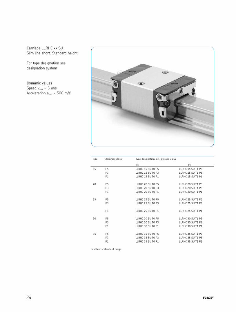
Carriage LLRHC xx SU
Slim line short. Standard height.
For type designation see
designation system
Dynamic values
Speed vmax = 5 m/s
Acceleration amax = 500 m/s2
Size Accuracy class Type designation incl. preload class
T0 T1
15 P5 LLRHC 15 SU T0 P5 LLRHC 15 SU T1 P5
P3 LLRHC 15 SU T0 P3 LLRHC 15 SU T1 P3
P1 LLRHC 15 SU T0 P1 LLRHC 15 SU T1 P1
20 P5 LLRHC 20 SU T0 P5 LLRHC 20 SU T1 P5
P3 LLRHC 20 SU T0 P3 LLRHC 20 SU T1 P3
P1 LLRHC 20 SU T0 P1 LLRHC 20 SU T1 P1
25 P5 LLRHC 25 SU T0 P5 LLRHC 25 SU T1 P5
P3 LLRHC 25 SU T0 P3 LLRHC 25 SU T1 P3
P1 LLRHC 25 SU T0 P1 LLRHC 25 SU T1 P1
30 P5 LLRHC 30 SU T0 P5 LLRHC 30 SU T1 P5
P3 LLRHC 30 SU T0 P3 LLRHC 30 SU T1 P3
P1 LLRHC 30 SU T0 P1 LLRHC 30 SU T1 P1
35 P5 LLRHC 35 SU T0 P5 LLRHC 35 SU T1 P5
P3 LLRHC 35 SU T0 P3 LLRHC 35 SU T1 P3
P1 LLRHC 35 SU T0 P1 LLRHC 35 SU T1 P1
bold text = standard range
25
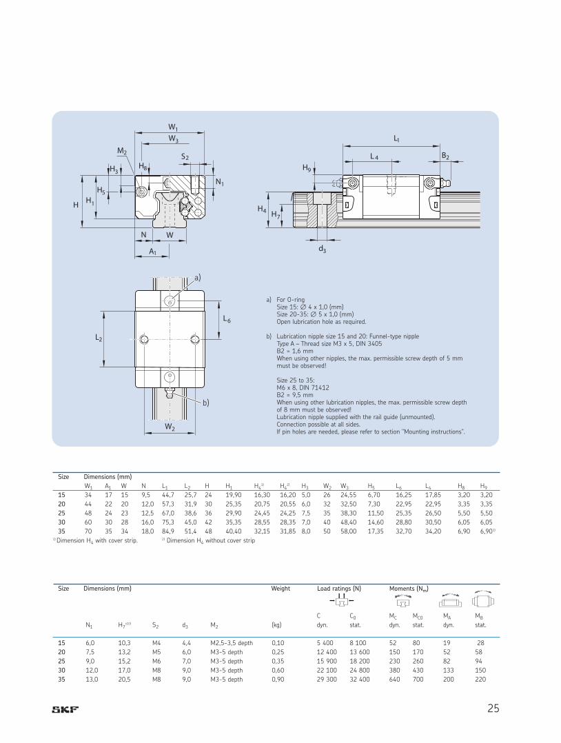
a) For O-ringSize 15: † 4 x 1,0 (mm)Size 20-35: † 5 x 1,0 (mm)Open lubrication hole as required.
b) Lubrication nipple size 15 and 20: Funnel-type nippleType A – Thread size M3 x 5, DIN 3405B2 = 1,6 mm When using other nipples, the max. permissible screw depth of 5 mm must be observed!
Size 25 to 35: M6 x 8, DIN 71412B2 = 9,5 mm When using other lubrication nipples, the max. permissible screw depth of 8 mm must be observed! Lubrication nipple supplied with the rail guide (unmounted).Connection possible at all sides.If pin holes are needed, please refer to section "Mounting instructions".
Size Dimensions (mm) Weight
C C0 MC MC0 MA MB
N1 H7±0,5 S2 d3 M2 (kg) dyn. stat. dyn. stat. dyn. stat.
15 6,0 10,3 M4 4,4 M2,5-3,5 depth 0,10 5 400 8 100 52 80 19 28
20 7,5 13,2 M5 6,0 M3-5 depth 0,25 12 400 13 600 150 170 52 58
25 9,0 15,2 M6 7,0 M3-5 depth 0,35 15 900 18 200 230 260 82 94
30 12,0 17,0 M8 9,0 M3-5 depth 0,60 22 100 24 800 380 430 133 150
35 13,0 20,5 M8 9,0 M3-5 depth 0,90 29 300 32 400 640 700 200 220
Size Dimensions (mm)
W1 A1 W N L1 L2 H H1 H41) H4
2) H3 W2 W3 H5 L6 L4 H8 H915 34 17 15 9,5 44,7 25,7 24 19,90 16,30 16,20 5,0 26 24,55 6,70 16,25 17,85 3,20 3,20
20 44 22 20 12,0 57,3 31,9 30 25,35 20,75 20,55 6,0 32 32,50 7,30 22,95 22,95 3,35 3,35
25 48 24 23 12,5 67,0 38,6 36 29,90 24,45 24,25 7,5 35 38,30 11,50 25,35 26,50 5,50 5,50
30 60 30 28 16,0 75,3 45,0 42 35,35 28,55 28,35 7,0 40 48,40 14,60 28,80 30,50 6,05 6,05
35 70 35 34 18,0 84,9 51,4 48 40,40 32,15 31,85 8,0 50 58,00 17,35 32,70 34,20 6,90 6,901)
1) Dimension H4 with cover strip.2) Dimension H4 without cover strip
Load ratings (N) Moments (Nm)

26
Carriage LLRHC xx U
Slim line normal. Standard height.
For type designation see
designation system
Dynamic values
Speed vmax = 5 m/s
Acceleration amax = 500 m/s2
Size Accuracy class Type designation incl. preload class
T0 T1 T2
15 P5 LLRHC 15 U T0 P5 LLRHC 15 U T1 P5 LLRHC 15 U T2 P5
P3 LLRHC 15 U T0 P3 LLRHC 15 U T1 P3 LLRHC 15 U T2 P3
P1 LLRHC 15 U T0 P1 LLRHC 15 U T1 P1 LLRHC 15 U T2 P1
20 P5 LLRHC 20 U T0 P5 LLRHC 20 U T1 P5 LLRHC 20 U T2 P5
P3 LLRHC 20 U T0 P3 LLRHC 20 U T1 P3 LLRHC 20 U T2 P3
P1 LLRHC 20 U T0 P1 LLRHC 20 U T1 P1 LLRHC 20 U T2 P1
25 P5 LLRHC 25 U T0 P5 LLRHC 25 U T1 P5 LLRHC 25 U T2 P5
P3 LLRHC 25 U T0 P3 LLRHC 25 U T1 P3 LLRHC 25 U T2 P3
P1 LLRHC 25 U T0 P1 LLRHC 25 U T1 P1 LLRHC 25 U T2 P1
30 P5 LLRHC 30 U T0 P5 LLRHC 30 U T1 P5 LLRHC 30 U T2 P5
P3 LLRHC 30 U T0 P3 LLRHC 30 U T1 P3 LLRHC 30 U T2 P3
P1 LLRHC 30 U T0 P1 LLRHC 30 U T1 P1 LLRHC 30 U T2 P1
35 P5 LLRHC 35 U T0 P5 LLRHC 35 U T1 P5 LLRHC 35 U T2 P5
P3 LLRHC 35 U T0 P3 LLRHC 35 U T1 P3 LLRHC 35 U T2 P3
P1 LLRHC 35 U T0 P1 LLRHC 35 U T1 P1 LLRHC 35 U T2 P1
45 P5 LLRHC 45 U T0 P5 LLRHC 45 U T1 P5 LLRHC 45 U T2 P5
P3 LLRHC 45 U T0 P3 LLRHC 45 U T1 P3 LLRHC 45 U T2 P3
P1 LLRHC 45 U T0 P1 LLRHC 45 U T1 P1 LLRHC 45 U T2 P1
bold text = standard range

27
a) For O-ringSize 15: † 4 x 1,0 (mm)Size 20-45: † 5 x 1,0 (mm)Open lubrication hole as required.
b) Lubrication nipple size 15 and 20: Funnel-type nippleType A – Thread size M3 x 5, DIN 3405B2 = 1,6 mm When using other nipples, the max. permissible screw depth of 5 mm must be observed!
Size 25 to 45: M6 x 8, DIN 71412B2 = 9,5 mm When using other lubrication nipples, the max. permissible screw depth of 8 mm must be observed! Lubrication nipple supplied with the rail guide (unmounted).Connection possible at all sides.If pin holes are needed, please refer to section "Mounting instructions".
Size Dimensions (mm) Weight
C C0 MC MC0 MA MB
N1 H7±0,5 S2 d3 M2 (kg) dyn. stat. dyn. stat. dyn. stat.
15 6,0 10,3 M4 4,4 M2,5-3,5 depth 0,15 7 800 13 500 74 130 40 71
20 7,5 13,2 M5 6,0 M3-5 depth 0,35 18 800 24 400 240 310 130 165
25 9,0 15,2 M6 7,0 M3-5 depth 0,50 22 800 30 400 320 430 180 240
30 12,0 17,0 M8 9,0 M3-5 depth 0,85 31 700 41 300 540 720 290 380
35 13,0 20,5 M8 9,0 M3-5 depth 1,25 41 900 54 000 890 1 160 440 565
45 18,0 23,5 M10 14,0 M4-7 depth 2,40 68 100 85 700 1 830 2 310 890 1 130
Size Dimensions (mm)
W1 A1 W N L1 L2 H H1 H41) H4
2) H3 W2 L3 W3 H5 L6 L4 H8 H915 34 17 15 9,5 58,2 39,2 24 19,90 16,30 16,20 5,0 26 26 24,55 6,70 10,00 11,60 3,20 3,20
20 44 22 20 12,0 75,0 49,6 30 25,35 20,75 20,55 6,0 32 36 32,50 7,30 13,80 13,80 3,35 3,35
25 48 24 23 12,5 86,2 57,8 36 29,90 24,45 24,25 7,5 35 35 38,30 11,50 17,45 18,60 5,50 5,50
30 60 30 28 16,0 97,7 67,4 42 35,35 28,55 28,35 7,0 40 40 48,40 14,60 20,00 21,70 6,05 6,05
35 70 35 34 18,0 110,5 77,0 48 40,40 32,15 31,85 8,0 50 50 58,00 17,35 20,50 22,00 6,90 6,90
45 86 43 45 20,5 137,6 97,0 60 50,30 40,15 39,85 10,0 60 60 69,80 20,90 27,30 29,30 8,20 8,201) Dimension H4 with cover strip.
2) Dimension H4 without cover strip
Load ratings (N) Moments (Nm)

28
Carriage LLRHC xx LU
Slim line normal. Standard height.
For type designation see
designation system
Dynamic values
Speed vmax = 5 m/s
Acceleration amax = 500 m/s2
Size Accuracy class Type designation incl. preload class
T0 T1 T2
15 P5 LLRHC 15 LU T0 P5 LLRHC 15 LU T1 P5 LLRHC 15 LU T2 P5
P3 LLRHC 15 LU T0 P3 LLRHC 15 LU T1 P3 LLRHC 15 LU T2 P3
P1 LLRHC 15 LU T1 P1 LLRHC 15 LU T2 P1
20 P5 LLRHC 20 LU T0 P5 LLRHC 20 LU T1 P5 LLRHC 20 LU T2 P5
P3 LLRHC 20 LU T0 P3 LLRHC 20 LU T1 P3 LLRHC 20 LU T2 P3
P1 LLRHC 20 LU T1 P1 LLRHC 20 LU T2 P1
25 P5 LLRHC 25 LU T0 P5 LLRHC 25 LU T1 P5 LLRHC 25 LU T2 P5
P3 LLRHC 25 LU T0 P3 LLRHC 25 LU T1 P3 LLRHC 25 LU T2 P3
P1 LLRHC 25 LU T1 P1 LLRHC 25 LU T2 P1
30 P5 LLRHC 30 LU T0 P5 LLRHC 30 LU T1 P5 LLRHC 30 LU T2 P5
P3 LLRHC 30 LU T0 P3 LLRHC 30 LU T1 P3 LLRHC 30 LU T2 P3
P1 LLRHC 30 LU T1 P1 LLRHC 30 LU T2 P1
35 P5 LLRHC 35 LU T0 P5 LLRHC 35 LU T1 P5 LLRHC 35 LU T2 P5
P3 LLRHC 35 LU T0 P3 LLRHC 35 LU T1 P3 LLRHC 35 LU T2 P3
P1 LLRHC 35 LU T1 P1 LLRHC 35 LU T2 P1
45 P5 LLRHC 45 LU T0 P5 LLRHC 45 LU T1 P5 LLRHC 45 LU T2 P5
P3 LLRHC 45 LU T0 P3 LLRHC 45 LU T1 P3 LLRHC 45 LU T2 P3
P1 LLRHC 45 LU T1 P1 LLRHC 45 LU T2 P1
bold text = Standard range

29
Size Dimensions (mm) Weight
C C0 MC MC0 MA MB
N1 H7±0,5 S2 d3 M2 (kg) dyn. stat. dyn. stat. dyn. stat.
15 6,0 10,3 M4 4,4 M2,5-3,5 depth 0,20 10 000 20 200 130 190 98 150
20 7,5 13,2 M5 6,0 M3-5 depth 0,45 24 400 35 200 310 450 225 330
25 9,0 15,2 M6 7,0 M3-5 depth 0,65 30 400 45 500 430 650 345 510
30 12,0 17,0 M8 9,0 M3-5 depth 1,10 40 000 57 800 690 1 000 495 715
35 13,0 20,5 M8 9,0 M3-5 depth 1,70 55 600 81 000 1 200 1 740 830 1 215
45 18,0 23,5 M10 14,0 M4-7 depth 3,20 90 400 128 500 2 440 3 470 1 700 2 425
Size Dimensions (mm)
W1 A1 W N L1 L2 H H1 H41) H42) H3 W2 L3 W3 H5 L6 L4 H8 H9
15 34 17 15 9,5 72,6 53,6 24 19,90 16,30 16,20 5,0 26 26 24,55 6,70 17,20 18,80 3,20 3,20
20 44 22 20 12,0 91,0 65,6 30 25,35 20,75 20,55 6,0 32 50 32,50 7,30 14,80 14,80 3,35 3,35
25 48 24 23 12,5 107,9 79,5 36 29,90 24,45 24,25 7,5 35 50 38,30 11,50 20,80 21,95 5,50 5,50
30 60 30 28 16,0 119,7 89,4 42 35,35 28,55 28,35 7,0 40 60 48,40 14,60 21,00 22,70 6,05 6,05
35 70 35 34 18,0 139,0 105,5 48 40,40 32,15 31,85 8,0 50 72 58,00 17,35 23,75 25,25 6,90 6,90
45 86 43 45 20,5 174,1 133,5 60 50,30 40,15 39,85 10,0 60 80 69,80 20,90 35,50 37,50 8,20 8,201) Dimension H4 with cover strip.
2) Dimension H4 without cover strip
Load ratings (N) Moments (Nm)
a) For O-ringSize 15: † 4 x 1,0 (mm)Size 20-45: † 5 x 1,0 (mm)Open lubrication hole as required.
b ) Lubrication nipple size 15 and 20: Funnel-type nippleType A – Thread size M3 x 5, DIN 3405B2 = 1,6 mm When using other nipples, the max. permissible screw depth of 5 mm must be observed!
Size 25 to 45: M6 x 8, DIN 71412B2 = 9,5 mm When using other lubrication nipples, the max. permissible screw depth of 8 mm must be observed! Lubrication nipple supplied with the rail guide (unmounted).Connection possible at all sides.If pin holes are needed, please refer to section "Mounting instructions".

30
Carriage LLRHC xx R
Slim line normal. High.
For type designation see
designation system
Dynamic values
Speed vmax = 5 m/s
Acceleration amax = 500 m/s2
Size Accuracy class Type designation incl. preload class
T0 T1 T2
15 P5 LLRHC 15 R T0 P5 LLRHC 15 R T1 P5 LLRHC 15 R T2 P5
P3 LLRHC 15 R T0 P3 LLRHC 15 R T1 P3 LLRHC 15 R T2 P3
P1 LLRHC 15 R T1 P1 LLRHC 15 R T2 P1
25 P5 LLRHC 25 R T0 P5 LLRHC 25 R T1 P5 LLRHC 25 R T2 P5
P3 LLRHC 25 R T0 P3 LLRHC 25 R T1 P3 LLRHC 25 R T2 P3
P1 LLRHC 25 R T1 P1 LLRHC 25 R T2 P1
30 P5 LLRHC 30 R T0 P5 LLRHC 30 R T1 P5 LLRHC 30 R T2 P5
P3 LLRHC 30 R T0 P3 LLRHC 30 R T1 P3 LLRHC 30 R T2 P3
P1 LLRHC 30 R T1 P1 LLRHC 30 R T2 P1
35 P5 LLRHC 35 R T0 P5 LLRHC 35 R T1 P5 LLRHC 35 R T2 P5
P3 LLRHC 35 R T0 P3 LLRHC 35 R T1 P3 LLRHC 35 R T2 P3
P1 LLRHC 35 R T1 P1 LLRHC 35 R T2 P1
45 P5 LLRHC 45 R T0 P5 LLRHC 45 R T1 P5 LLRHC 45 R T2 P5
P3 LLRHC 45 R T0 P3 LLRHC 45 R T1 P3 LLRHC 45 R T2 P3
P1 LLRHC 45 R T1 P1 LLRHC 45 R T2 P1
bold text = Standard range

31
a) For O-ringSize 15: † 4 x 1,0 (mm)Size 20-45: † 5 x 1,0 (mm)Open lubrication hole as required.
b ) Lubrication nipple size 15 and 20: Funnel-type nippleType A – Thread size M3 x 5, DIN 3405B2 = 1,6 mm When using other nipples, the max. permissible screw depth of 5 mm must be observed!
Size 25 to 45: M6 x 8, DIN 71412B2 = 9,5 mm When using other lubrication nipples, the max. permissible screw depth of 8 mm must be observed! Lubrication nipple supplied with the rail guide (unmounted).Connection possible at all sides.If pin holes are needed, please refer to section "Mounting instructions".
Size Dimensions (mm) Weight
C C0 MC MC0 MA MB
N1 H7±0,5 S2 d3 M2 (kg) dyn. stat. dyn. stat. dyn. stat.
15 6,0 10,3 M4 4,4 M2,5-3,5 depth 0,20 7 800 13 500 74 130 40 71
25 9,0 15,2 M6 7,0 M3-5 depth 0,60 22 800 30 400 320 430 180 240
30 12,0 17,0 M8 9,0 M3-5 depth 0,95 31 700 41 300 540 720 290 380
35 13,0 20,5 M8 9,0 M3-5 depth 1,55 41 900 54 000 890 1 160 440 565
45 18,0 23,5 M10 14,0 M4-7 depth 3,00 68 100 85 700 1 830 2 310 890 1130
Size Dimensions (mm)
W1 A1 W N L1 L2 H H1 H41) H4
2) H3 W2 L3 W3 H5 L6 L4 H8 H915 34 17 15 9,5 58,2 39,2 28 23,90 16,30 16,20 5,0 26 26 24,55 10,70 10,00 11,60 7,20 7,20
25 48 24 23 12,5 86,2 57,8 40 33,90 24,45 24,25 7,5 35 35 38,30 15,50 17,45 18,60 9,50 9,50
30 60 30 28 16,0 97,7 67,4 45 38,35 28,55 28,35 7,0 40 40 48,40 17,60 20,00 21,70 9,05 9,05
35 70 35 34 18,0 110,5 77,0 55 47,40 32,15 31,85 8,0 50 50 58,00 24,35 20,50 22,00 13,90 13,90
45 86 43 45 20,5 137,6 97,0 70 60,30 40,15 39,85 10,0 60 60 69,80 30,90 27,30 29,30 18,20 18,201) Dimension H4 with cover strip.
2) Dimension H4 without cover strip
Load ratings (N) Moments (Nm)

32
Carriage LLRHC xx LR
Slim line long. High.
For type designation see
designation system
Dynamic values
Speed vmax = 5 m/s
Acceleration amax = 500 m/s2
Size Accuracy class Type designation incl. preload class
T0 T1 T2
25 P5 LLRHC 25 LR T0 P5 LLRHC 25 LR T1 P5 LLRHC 25 LR T2 P5
P3 LLRHC 25 LR T0 P3 LLRHC 25 LR T1 P3 LLRHC 25 LR T2 P3
P1 LLRHC 25 LR T1 P1 LLRHC 25 LR T2 P1
30 P5 LLRHC 30 LR T0 P5 LLRHC 30 LR T1 P5 LLRHC 30 LR T2 P5
P3 LLRHC 30 LR T0 P3 LLRHC 30 LR T1 P3 LLRHC 30 LR T2 P3
P1 LLRHC 30 LR T1 P1 LLRHC 30 LR T2 P1
35 P5 LLRHC 35 LR T0 P5 LLRHC 35 LR T1 P5 LLRHC 35 LR T2 P5
P3 LLRHC 35 LR T0 P3 LLRHC 35 LR T1 P3 LLRHC 35 LR T2 P3
P1 LLRHC 35 LR T1 P1 LLRHC 35 LR T2 P1
45 P5 LLRHC 45 LR T0 P5 LLRHC 45 LR T1 P5 LLRHC 45 LR T2 P5
P3 LLRHC 45 LR T0 P3 LLRHC 45 LR T1 P3 LLRHC 45 LR T2 P3
P1 LLRHC 45 LR T1 P1 LLRHC 45 LR T2 P1
bold text = Standard range

33
a) For O-ringSize 20-45: † 5 x 1,0 (mm)Open lubrication hole as required.See additional elements: Mounting of lubrication adapter.
b) Lubrication nipple size 25 to 45: M6 x 8, DIN 71412B2 = 9,5 mm When using other lubrication nipples, the max. permissible screw depth of 8 mm must be observed! Lubrication nipple supplied with the rail guide (unmounted).Connection possible at all sides.If pin holes are needed, please refer to section "Mounting instructions".
Size Dimensions (mm) Weight
C C0 MC MC0 MA MB
N1 H7±0,5 S2 d3 M2 (kg) dyn. stat. dyn. stat. dyn. stat.
25 9,0 15,2 M6 7,0 M3-5 depth 0,80 30 400 45 500 430 650 345 510
30 12,0 17,0 M8 9,0 M3-5 depth 1,20 40 000 57 800 690 1 000 495 715
35 13,0 20,5 M8 9,0 M3-5 depth 2,10 55 600 81 000 1 200 1 740 830 1 215
45 18,0 23,5 M10 14,0 M4-7 depth 4,10 90 400 128 500 2 440 3 470 1 700 2 425 3)
Size Dimensions (mm)
W1 A1 W N L1 L2 H H1 H41) H4
2) H3 W2 L3 W3 H5 L6 L4 H8 H925 48 24 23 12,5 107,9 79,5 40 33,90 24,45 24,25 7,5 35 50 38,30 15,50 20,80 21,95 9,50 9,50
30 60 30 28 16,0 119,7 89,4 45 38,35 28,55 28,35 7,0 40 60 48,40 17,60 21,00 22,70 9,05 9,05
35 70 35 34 18,0 139,0 105,5 55 47,40 32,15 31,85 8,0 50 72 58,00 24,35 23,75 25,25 13,90 13,90
45 86 43 45 20,5 174,1 133,5 70 60,30 40,15 39,85 10,0 60 80 69,80 30,90 35,50 37,50 18,20 18,201) Dimension H4 with cover strip.
2) Dimension H4 without cover strip
Load ratings (N) Moments (Nm)

34

35
Rails with protective caps made of
plastics
Rails with cover strip and cover
strip retaining clamps made of alu-
minium
- without end face threaded holes
(not required)
Standard rails
Product overview

36
LLRHR rails
For mounting from above with pla-
stic mounting caps (supplied).
Note
The rails can also be supplied in
several parts.
Type designation and rail lengths
Standard rail Rail Rail Pitchone-piece multi-piece T
Size Accuracy Designation Designation [mm]
15 P5 LLRHR 15 - xxxx P5 LLRHR 15 - xxxx P5 A 60
P3 LLRHR 15 - xxxx P3 LLRHR 15 - xxxx P3 A
P1 LLRHR 15 - xxxx P1 LLRHR 15 - xxxx P1 A
P01 LLRHR 15 - xxxx P01 LLRHR 15 - xxxx P01 A
P001 LLRHR 15 - xxxx P001 LLRHR 15 - xxxx P001 A
20 P5 LLRHR 20 - xxxx P5 LLRHR 20 - xxxx P5 A 60
P3 LLRHR 20 - xxxx P3 LLRHR 20 - xxxx P3 A
P1 LLRHR 20 - xxxx P1 LLRHR 20 - xxxx P1 A
P01 LLRHR 20 - xxxx P01 LLRHR 20 - xxxx P01 A
P001 LLRHR 20 - xxxx P001 LLRHR 20 - xxxx P001 A
25 P5 LLRHR 25 - xxxx P5 LLRHR 25 - xxxx P5 A 60
P3 LLRHR 25 - xxxx P3 LLRHR 25 - xxxx P3 A
P1 LLRHR 25 - xxxx P1 LLRHR 25 - xxxx P1 A
P01 LLRHR 25 - xxxx P01 LLRHR 25 - xxxx P01 A
P001 LLRHR 25 - xxxx P001 LLRHR 25 - xxxx P001 A
30 P5 LLRHR 30 - xxxx P5 LLRHR 30 - xxxx P5 A 80
P3 LLRHR 30 - xxxx P3 LLRHR 30 - xxxx P3 A
P1 LLRHR 30 - xxxx P1 LLRHR 30 - xxxx P1 A
P01 LLRHR 30 - xxxx P01 LLRHR 30 - xxxx P01 A
P001 LLRHR 30 - xxxx P001 LLRHR 30 - xxxx P001 A
35 P5 LLRHR 35 - xxxx P5 LLRHR 35 - xxxx P5 A 80
P3 LLRHR 35 - xxxx P3 LLRHR 35 - xxxx P3 A
P1 LLRHR 35 - xxxx P1 LLRHR 35 - xxxx P1 A
P01 LLRHR 35 - xxxx P01 LLRHR 35 - xxxx P01 A
P001 LLRHR 35 - xxxx P001 LLRHR 35 - xxxx P001 A
45 P5 LLRHR 45 - xxxx P5 LLRHR 45 - xxxx P5 A 105
P3 LLRHR 45 - xxxx P3 LLRHR 45 - xxxx P3 A
P1 LLRHR 45 - xxxx P1 LLRHR 45 - xxxx P1 A
P01 LLRHR 45 - xxxx P01 LLRHR 45 - xxxx P01 A
P001 LLRHR 45 - xxxx P001 LLRHR 45 - xxxx P001 A
bold text = standard range
xxxx = rail length
Accuracy classes, dimensions and designations

The “E” dimension designates the
distance from the rail end to the
centre of the first attachment hole.
If no customer-specific “E” dimen-
sion is provided with the order, the
rails are produced according to the
following formula:
L - (z -1) x F2
37
Size Dimensions (mm) Weight
W H4 H7±0,5 d2 d3 E1 min F Lmax kg/m
15 15 16,20 10,3 7,4 4,4 10 60 4 000 1,4
20 20 20,55 13,2 9,4 6,0 10 60 4 000 2,4
25 23 24,25 15,2 11,0 7,0 10 60 4 000 3,2
30 28 28,35 17,0 15,0 9,0 12 80 4 000 5,0
35 34 31,85 20,5 15,0 9,0 12 80 4 000 6,8
45 45 39,85 23,5 20,0 14,0 16 105 4 000 10,5
E =
The distance of the first and last
attachment holes is mediated.
If several possibilities arise, the
shorter “E” dimension will be pro-
duced!
E = Rail end dimension
F = Distance of attachment holes
L = Rail length
z = Number of attachment holes

38
LLRHR D2 rails
For mounting from above with cover
strip and strip retaining clamps.
• Robust cover strip retaining
clamps made of aluminium
• Rail without end face threaded
holes (not required for cover
strip retaining clamps)
Note
The rails can also be supplied in
several parts.
Type designation and rail lengths Standard rail Rail Rail Pitchone-piece multi-piece T
Size Accuracy Designation Designation [mm]
15 P5 D2 LLRHR 15 - xxxx P5 D2 LLRHR 15 - xxxx P5 A D2 60
P3 D2 LLRHR 15 - xxxx P3 D2 LLRHR 15 - xxxx P3 A D2
P1 D2 LLRHR 15 - xxxx P1 D2 LLRHR 15 - xxxx P1 A D2
P01 D2 LLRHR 15 - xxxx P01 D2 LLRHR 15 - xxxx P01 A D2
P001 D2 LLRHR 15 - xxxx P001 D2 LLRHR 15 - xxxx P001 A D2
20 P5 D2 LLRHR 20 - xxxx P5 D2 LLRHR 20 - xxxx P5 A D2 60
P3 D2 LLRHR 20 - xxxx P3 D2 LLRHR 20 - xxxx P3 A D2
P1 D2 LLRHR 20 - xxxx P1 D2 LLRHR 20 - xxxx P1 A D2
P01 D2 LLRHR 20 - xxxx P01 D2 LLRHR 20 - xxxx P01 A D2
P001 D2 LLRHR 20 - xxxx P001 D2 LLRHR 20 - xxxx P001 A D2
25 P5 D2 LLRHR 25 - xxxx P5 D2 LLRHR 25 - xxxx P5 A D2 60
P3 D2 LLRHR 25 - xxxx P3 D2 LLRHR 25 - xxxx P3 A D2
P1 D2 LLRHR 25 - xxxx P1 D2 LLRHR 25 - xxxx P1 A D2
P01 D2 LLRHR 25 - xxxx P01 D2 LLRHR 25 - xxxx P01 A D2
P001 LLRHR 25 - xxxx P001 D2 LLRHR 25 - xxxx P001 A D2
30 P5 D2 LLRHR 30 - xxxx P5 D2 LLRHR 30 - xxxx P5 A D2 80
P3 D2 LLRHR 30 - xxxx P3 D2 LLRHR 30 - xxxx P3 A D2
P1 D2 LLRHR 30 - xxxx P1 D2 LLRHR 30 - xxxx P1 A D2
P01 D2 LLRHR 30 - xxxx P01 D2 LLRHR 30 - xxxx P01 A D2
P001 D2 LLRHR 30 - xxxx P001 D2 LLRHR 30 - xxxx P001 A D2
35 P5 D2 LLRHR 35 - xxxx P5 D2 LLRHR 35 - xxxx P5 A D2 80
P3 D2 LLRHR 35 - xxxx P3 D2 LLRHR 35 - xxxx P3 A D2
P1 D2 LLRHR 35 - xxxx P1 D2 LLRHR 35 - xxxx P1 A D2
P01 D2 LLRHR 35 - xxxx P01 D2 LLRHR 35 - xxxx P01 A D2
P001 D2 LLRHR 35 - xxxx P001 D2 LLRHR 35 - xxxx P001 A D2
45 P5 D2 LLRHR 45 - xxxx P5 D2 LLRHR 45 - xxxx P5 A D2 105
P3 D2 LLRHR 45 - xxxx P3 D2 LLRHR 45 - xxxx P3 A D2
P1 D2 LLRHR 45 - xxxx P1 D2 LLRHR 45 - xxxx P1 A D2
P01 D2 LLRHR 45 - xxxx P01 D2 LLRHR 45 - xxxx P01 A D2
P001 D2 LLRHR 45 - xxxx P001 D2 LLRHR 45 - xxxx P001 A D2
bold text = standard range
xxxx = rail length
L - (z -1) x F2
39
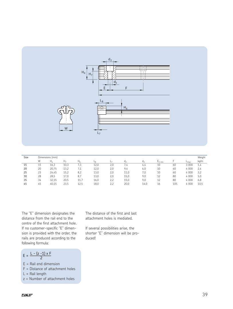
The “E” dimension designates the
distance from the rail end to the
centre of the first attachment hole.
If no customer-specific “E” dimen-
sion is provided with the order, the
rails are produced according to the
following formula:
The distance of the first and last
attachment holes is mediated.
If several possibilities arise, the
shorter “E” dimension will be pro-
duced!
Size Dimensions (mm) Weight
W H4 H7 H6 L8 L7 d2 d3 E1 min F Lmax kg/m
15 15 16,3 10,3 7,3 12,0 2,0 7,4 4,4 10 60 3 000 1,4
20 20 20,75 13,2 7,1 12,0 2,0 9,4 6,0 10 60 4 000 2,4
25 23 24,45 15,2 8,2 13,0 2,0 11,0 7,0 10 60 4 000 3,2
30 28 28,5 17,0 8,7 13,0 2,0 15,0 9,0 12 80 4 000 5,0
35 34 32,15 20,5 11,7 16,0 2,2 15,0 9,0 12 80 4 000 6,8
45 45 40,15 23,5 12,5 18,0 2,2 20,0 14,0 16 105 4 000 10,5
E =
E = Rail end dimension
F = Distance of attachment holes
L = Rail length
z = Number of attachment holes

L L R H
TypeBellows (for bellows only)* BCarriage (carriage only)* CRail (rail only)* RSystem (carriage and rail)** SAccessories, if ordered separately* Z
Carriage size (write relevant number)15, 20, 25, 30, 35, 45 XX
Carriage typeFlange short, standard height SAFlange normal, standard height AFlange long, standard height LASlim line short, standard height SUSlim line normal, standard height USlim line long, standard height LUSlim line normal, high RSlim line long, high LR
Carriage with ball retainer (If not selected - no code)Yes B
Number of carriages per rail1, 2, 4, 6, ... X
Preload classPlay T0Light preload, 0,02 x C T1Medium preload, 0,08 x C T2Heavy preload, 0,13 x C T3
Rail length80 mm - 4 000 mm (step in 1 mm) XXXX
Precision classStandard P5Medium P3High P1Super P01Ultra P001
No. of parallel mounted rail tracks in customized application (If not selected - no code)2, 3, .... (write relevant number for "x") Wx
Jointed rail track (If not selected - no code)Yes A
Bellows (If not selected - no code)System complete with bellows BKit, type 2 (carriage thru the end of the rail)* B2Kit, type 4 (between two carriages)* B4
Cover stripOrdered separately* CSGuard type 2 (aluminium)* CSG
RailRail, if customized according to drawing number DRail, with cover strip and cover strip guard type 2 (aluminium) D2
Distance between end face and first hole of the rail"E" dimension to be calculated - see page 37 or 39 EIf no "E" specified the holes will be symmetric 0
Coating (If not selected - no code)Duralloy, coated system (balls and tracks are not coated) HD
System, (carriage mounted on rail, acc. not mounted) (If not selected - no code)Yes M
Lubrication adapter, option for high carriages (If not selected - no code)Yes O
SealingScraper plate S1Two piece front seal S2Seal kit, two piece front seal with scraper plate S3
Arbour for creating a sliding fit for the cover strip (If not selected - no code)Yes W
* When ordered separately (not in a system). ** System consisting of carriage and railAn key with all positions in fat blue fonts qualifies the product for the easy range concept (quick delivery).
40
Ordering key

41
Notes

42
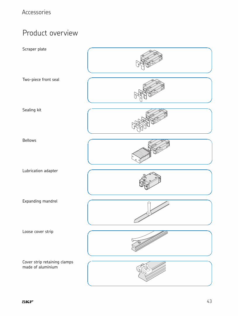
43
Scraper plate
Two-piece front seal
Sealing kit
Bellows
Lubrication adapter
Expanding mandrel
Loose cover strip
Cover strip retaining clampsmade of aluminium
Accessories
Product overview

44
Scraper plate
• Material: stainless spring steel
to DIN EN 10088
• Condition: bright
• Precision design with 0,2 to
0,3 mm maximum gap
measurement
Mounting:
Fastening screws are supplied.
During mounting please ensure an
even gap between the rail and
scraper plate.
Scraper plate for rails with and
without cover strip
Note:
Use in combination with two-piece
front seal kit LLRHZxxS3.
Standard carriages
Size Part numbers Dimensions (mm) Weight (g)A A1 H2 W3 E9 S2 S3 D
15 LLRHZ 15 S1 33 26,4 19,2 24,55 6,3 4,6 3,5 1,0 4
20 LLRHZ 20 S1 42 40,0 24,8 32,4 6,8 5,1 4 1,0 6
25 LLRHZ 25 S1 47 41,6 29,5 38,3 11,0 7 4 1,0 8
30 LLRHZ 30 S1 59 52,8 34,7 48,4 14,1 7 4 1,0 12
35 LLRHZ 35 S1 69 60,9 40,1 58,0 17,0 7 4 1,0 16
35* LLRHZ 35 S1 CS 69 60,9 40,1 58,0 17,0 7 4 1,0 16
45 LLRHZ 45 S1 85 76,7 50,0 69,8 20,5 7 5 2,0 50
45* LLRHZ 45 S1 CS 85 76,7 50,0 69,8 20,5 7 5 2,0 50
* Scraper plates in combination with cover strip
45
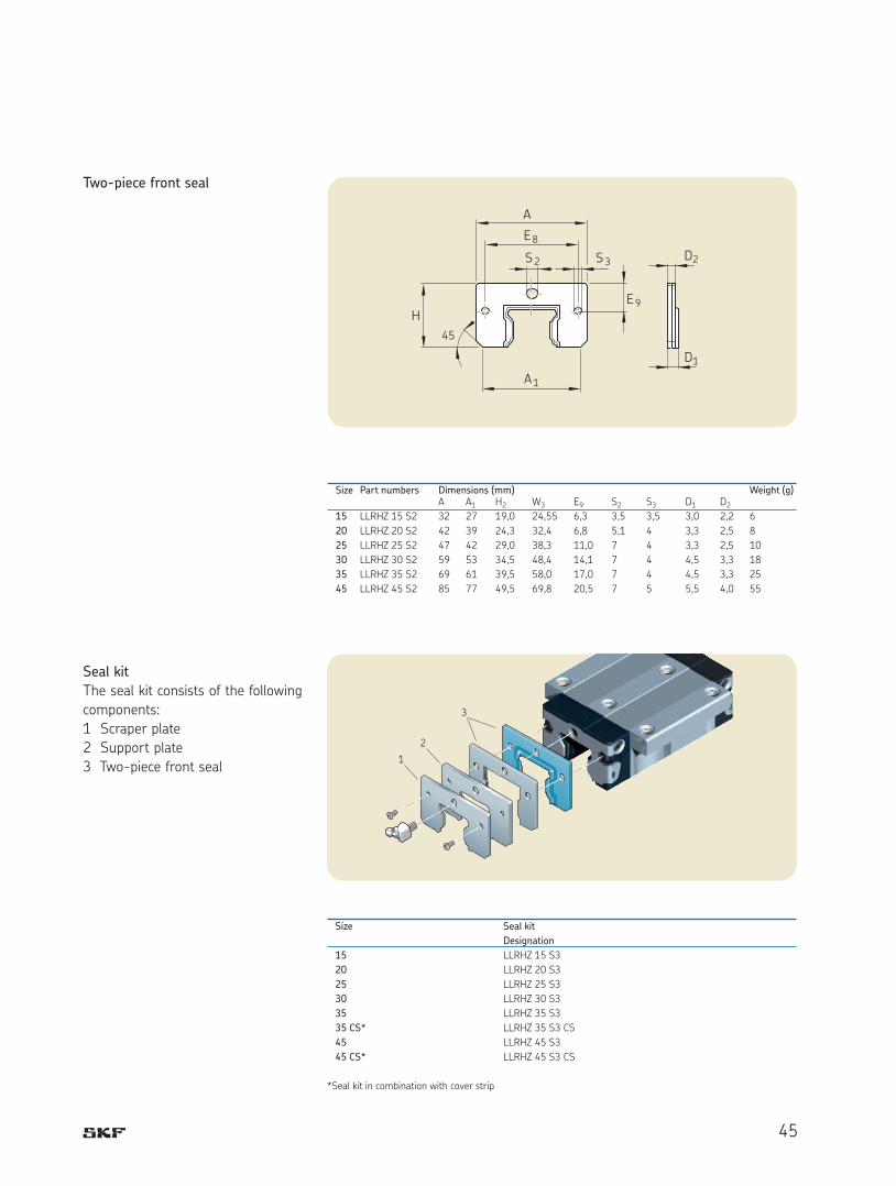
Two-piece front seal
Seal kit
The seal kit consists of the following
components:
1 Scraper plate
2 Support plate
3 Two-piece front seal
Size Part numbers Dimensions (mm) Weight (g)A A1 H2 W3 E9 S2 S3 D1 D2
15 LLRHZ 15 S2 32 27 19,0 24,55 6,3 3,5 3,5 3,0 2,2 6
20 LLRHZ 20 S2 42 39 24,3 32,4 6,8 5,1 4 3,3 2,5 8
25 LLRHZ 25 S2 47 42 29,0 38,3 11,0 7 4 3,3 2,5 10
30 LLRHZ 30 S2 59 53 34,5 48,4 14,1 7 4 4,5 3,3 18
35 LLRHZ 35 S2 69 61 39,5 58,0 17,0 7 4 4,5 3,3 25
45 LLRHZ 45 S2 85 77 49,5 69,8 20,5 7 5 5,5 4,0 55
Size Seal kit
Designation
15 LLRHZ 15 S3
20 LLRHZ 20 S3
25 LLRHZ 25 S3
30 LLRHZ 30 S3
35 LLRHZ 35 S3
35 CS* LLRHZ 35 S3 CS
45 LLRHZ 45 S3
45 CS* LLRHZ 45 S3 CS
*Seal kit in combination with cover strip

46
Lubrication adapter
For high carriages:
LLRHC_R
LLRHC_LR
• Material: plastic
• Contents: 1 piece
Mounting:
O-rings are supplied.
Type designations and dimensions
Size Part numbers Dimensions (mm)
D D1 D2 F F1 F2 F315 LLRHZ 15 0 12 6,2 3,4 3,70 3,10 0,50 3,20
25 LLRHZ 25 0 15 7,2 4,4 3,80 3,20 0,50 5,85
30 LLRHZ 30 0 16 7,2 4,4 2,80 2,20 0,50 6,10
35 LLRHZ 35 0 18 7,2 4,4 6,80 6,20 0,50 6,80
45 LLRHZ 45 0 20 7,2 4,4 9,80 9,20 0,50 8,30

47
Mounting of lubrication adapter
A lubrication adapter is necessary on
high carriages if lubrication is to take
place from the table part.
In the recess for the O-ring
seal a further small recess (1) has
been preformed. Do not drill this
open. Risk of dirt incursion!
• Heat up metal tip (2) with a
diameter of 0,8 mm.
• Carefully open the recess (1)
with the metal tip and push
through.
Observe maximum permissible
depth Tmax stated in the
table!
• Insert O-ring seal (3) in the
recess.
• Insert lubrication adapter at an
angle in the recess and press
the flattened side (4) onto the
steel part (5). Use grease for
fixing.
• Insert O-ring seal (6) in the
lubrication adapter.
Size
Top lubrication opening: maximum
permissible depth for penetration
Tmax (mm)
4
6
3
1
5
2
8
M6
51,6
M3
Size Top lubrication opening:
maximum permissible depth
for penetration Tmax (mm)
15 3,6
20 3,9
25 3,3
30 6,6
35 7,5
45 8,8
Lubrication nipple dimensions
DIN 71412, cone-type nipple
for carriage size 25, 30, 35 and 45
DIN 3405, funnel-type nipple
for carriage size 15 and 20

48
Bellows
Material:
Bellows are made out of polyester
fabric with polyurethane coating
Adapter plates are made out of
aluminium.
The lubrication nipple on the
carriage can be used.
15 LLRHB 15 B2 xx LLRHB 15 B4 xx LLRHB 15 xx
20 LLRHB 20 B2 xx LLRHB 20 B4 xx LLRHB 20 xx
25 LLRHB 25 B2 xx LLRHB 25 B4 xx LLRHB 25 xx
30 LLRHB 30 B2 xx LLRHB 30 B4 xx LLRHB 30 xx
35 LLRHB 35 B2 xx LLRHB 35 B4 xx LLRHB 35 xx
45 LLRHB 45 B2 xx LLRHB 45 B4 xx LLRHB 45 xx
xx = Number of folds
Size Type 2 with fastening plate for the carriage and end plate for the rail
Type 4 with two fastening plates for the carriages
Type 9 loose bellows (spare part)

49
Mounting
The bellows are pre-mounted.
The fixing screws are supplied.
On type 2 in each case one thread
M4-10 deep, 2 x 45º countersunk,
must be inserted in the end face of
the rail.
Size 25 - 45:
The lubrication nipple on the car-
riage can be used.
Size 15 and 20:
A drive-type lubrication nipple is
supplied.
Calculation of the bellows
LA = Carriage length L1 plus
2x12 mm for the fastening
plates.
Lmax = Bellows stretched
Lmin = Bellows pushed
together
Stroke = Stroke (mm)
U = Calculation factor
W = Maximum extension
of folds
Dimensions of the bellows
Lmin = Lmax - Stroke
Lmax = (Stroke + 30) · U
Number of folds = + 2LmaxW
L = Lmin + Lmax + LA L = Rail length (mm)
Calculation of the rail length
Size Dimensions (mm) Factor
A4 B3 H H3 H4 N7 N8 S7 S8 S9 W U
15 45 11 24 26,5 31,5 11 3,4 M4 ø3 M3 19,9 1,18
20 42 12 30 24,0 29,2 13 3,5 M4 ø3 M3 10,3 1,33
25 45 12 36 28,5 35,0 15 6,0 M4 M6 M3 12,9 1,32
30 55 12 42 34,0 41,0 18 8,0 M4 M6 M6 15,4 1,25
35 64 12 48 39,0 47,0 22 8,0 M4 M6 M6 19,9 1,18
45 83 12 60 49,0 59,0 30 8,0 M4 M6 M6 26,9 1,13

50
Advantages of the cover strip
The cover strip can be simply
clipped on and pulled off.
• This considerably simplifies
and quickens mounting:
- It is not necessary to close
every single drill hole
- It is not necessary to wait
for the adhesive to set on
adhesive strips.
• Multiple mounting and
removal is possible
(up to 4 times)
Designs/Functions
Cover strip with fixed seat
(standard)
• The cover strip is clipped on
before the carriages are
mounted and stays firmly in
place.
With an optionally available expand-
ing mandrel for 0,15 mm cover
strips or a special expanding tool for
0,3 mm cover strips a slide can also
be retroactively created in order to
remove a cover strip.
In particular, however, the slide
length X can be optimally adapted to
the specific application.
Please observe the precise
mounting instructions!
X
X
Cover strip

51
Cover strip for initial mounting/
stock/replacement
For each guide rail length a match-
ing cover strip with fixed seat can be
supplied.
Ordering a standard cover strip
with fixed seat
Example:
Rail Size 35,
Rail length L = 2 696 mm
LLRHZ 15 – 2 969 CS
(For order designation see
product table)
Expanding mandrel to create a slide
on the cover strip
Size Standard cover strips
Order designation, length (mm)
15 LLRHZ 15 - xxx CS
20 LLRHZ 20 - xxx CS
25 LLRHZ 25 - xxx CS
30 LLRHZ 30 - xxx CS
35 LLRHZ 35 - xxx CS
45 LLRHZ 45 - xxx CS
Size Expanding mandrel
Order designation
15 LLRHZ 15 W
20 LLRHZ 20 W
25 LLRHZ 25 W
30 LLRHZ 30 W
35 LLRHZ 35 W
45 LLRHZ 45 W

52

53
Cover strip retaining clamps
For guide rails without end-face
threaded holes.
SKF recommends the use of cover
strip retaining clamps.
These can:
• prevent unintentional removal
of the strip and incursion
of dirt
• fix the cover strip in place
Materials:
Retaining clamps made of alumini-
um, black anodised.
Clamping screw and nut made of
corrosion-resistant steel.
Order designations for cover strip
retaining clamps
Plastic caps are supplied as standard
if a cover strip has not been
ordered.
Size Retaining clamps (2 pieces per unit) Dimensions (mm)
Order designation
H6 L7 L8
15 LLR 15 CSG 7,3 2,0 12
20 LLR 20 CSG 7,1 2,0 12
25 LLR 25 CSG 8,2 2,0 13
30 LLR 30 CSG 8,7 2,0 13
35 LLR 35 CSG 11,7 2,2 16
45 LLR 45 CSG 12,5 2,2 18

54
General instructions
The following mounting instructions
apply to all profile rail guides.
Please note, however, that differ-
ing specifications exist concerning
the parallelism of the rails as well as
the screwing and pinning of the car-
riages. These are therefore assigned
to the individual versions.
Ball profile rail guides. are high-
quality products. Greatest possible
care should be taken during trans-
port and subsequent assembly. All
steel parts have been oil-protected.
The protection materials do not
need to be removed if the recom-
mended lubricants are used.
Note
The rail must have a chamfer to
prevent the seal from being dam-
aged. This is not the case for joint
rail tracks
Rails without lateral fixing must be
aligned straight and parallel during
assembly, preferably using an auxil-
iary strip.
(Guide values for the permissible
lateral force without additional later-
al fixing can be obtained from the
information for the individual ver-
sions).
Assembly examples
Rails:
Each rail has ground reference
edges on both sides.
Options for lateral fixing:
1 Stop edges
2 Clamp strips
3 Wedge strips
Mounting instructions
General mounting instructions
Carriage:
Each carriage has a ground refer-
ence edge on one side (<dimension
H3 in the dimensional drawings).
Additional fixing options:
1 Reference edges
2 Retaining strips
3 Clamp strips
4 Pinning
Note
After being successfully mounted the
carriage should move easily when
pushed.
Detailed mounting instructions are
available through your normal SKF
contact.

55
Stop edges, corner radii, screw
sizes and tightening torques
Carriages made of steel,
type A, LA
• Standard width
Rails
• Can be screwed from above
Carriages made of steel, type U,
LU, R, LR
Rails
• Can be screwed from above
Dimensions and guide values for
permissible lateral force without
additional lateral fixing
Tightening torques of the
fixing screws in Nm
h1 r1 h2 r2 O1 O22) O4
1)2) O5 O3 O6 N8Size min. max. max. max. DIN 912 DIN 6912 DIN 912 DIN 912 DIN 912 DIN 912
(mm) (mm) (mm) (mm) (mm) 4 Pieces 2 Pieces 6 Pieces 4 Pieces (mm)
15 2,5 3,5 0,4 4 0,6 M4x12 M4x10 M5x12 M4x12 M4x20 M5x12 6
20 2,5 4,0 0,6 5 0,6 M5x16 M5x12 M6x16 M5x16 M5x25 M6x16 9
25 3,0 5,0 0,8 5 0,8 M6x20 M6x16 M8x20 M6x18 M6x30 M6x20 10
30 3,0 5,0 0,8 6 0,8 M8x25 M8x16 M10x20 M8x20 M8x30 M8x20 10
35 3,5 6,0 0,8 6 0,8 M8x25 M8x20 M10x25 M8x25 M8x35 M8x25 13
45 4,5 8,0 0,8 8 0,8 M10x30 M10x25 M12x30 M10x30 M12x45 M12x30 14
Screw strength Carriages Rails
class
Carriages A, U, R 8.8 0,11 C 0,15 C3) 0,23 C 0,11 C 0,06 C 0,06 C
12.9 0,18 C 0,22 C3) 0,35 C 0,18 C 0,10 C 0,10 C
Carriages LA, LU, LR 8.8 0,08 C 0,13 C3) 0,18 C 0,08 C 0,04 C 0,04 C
12.9 0,14 C 0,18 C3) 0,26 C 0,14 C 0,07 C 0,07 C
M4 M5 M6 M8 M10 M12 M14 M16
8.8 2,7 5,5 9,5 23 46 80 125 195
12.9 4,6 9,5 16 39 77 135 215 340
1) If the carriage is fastened from above with only four O4 screws:
• permissible lateral force 1/3 lower
• lower stiffness2) If the carriage is fastened with 6 screws:
Tighten the middle screws with a tightening torque for strength class 8.83) If fastened with two O2 screws and four O1 screws
The combinations shown are examples. In principle all carriages can be
combined with all rails.

56
Pinning
If the guide values for the permissi-
ble lateral force are exceeded (see
table) the carriage must be addition-
ally fixed by means of pinning or
stop edges.
The recommended dimensions for
the pin holes can be obtained from
the drawings and table.
Usable pins:
• tapered pin (hardened) or
• straight pin DIN ISO 8734
Instructions
For production-related reasons there
may be pilot drill holes in the middle
of the carriage at the recommended
positions for pin holes († < S10).
They are suitable for drilling.
If necessary, the pinning must be
carried out in a different position
(e.g. middle lube port), but must not
exceed the dimension L3 in longitu-
dinal direction (L3 can be obtained
from the dimension tables for the
individual versions).
Keep to dimensions W2 and W4!
Do not complete the pin holes
until after mounting (see also gen-
eral mounting instructions - avail-
able through your normal SKF con-
tact).
Standard width A, LA
Slim line U, LUSlim line high R, LR
Size Dimensions (mm)
Tapered pin (hardened) or
straight pin (DIN 6325)
S10 L10 W2 W4 N9 (max)
15 4 18 26 38 6,0
20 5 24 32 53 7,5
25 6 32 35 55 9,0
30 8 36 40 70 12,0
35 8 40 50 80 13,0
45 10 50 60 98 18,0

57
Stop edges, corner radii, screw
sizes and tightening torques
Carriages SA
• Standard width, short
Rails
• Can be screwed from above
Carriages SU
• Slim line short
Rails
• Can be screwed from above
Dimensions and guide values for permissible lateral force without additional lateral fixing
Size h1 r1 h2 r2 O1 O4 O5 O3 O6 N8min. max. max. max. DIN 912 DIN 912 DIN 912 DIN 912 DIN 912
(mm) (mm) (mm) (mm) (mm) 2 Pieces 2 Pieces 2 Pieces (Rail) (Rail) (mm)
15 2,5 3,5 0,4 4 0,6 M4x12 M5x12 M4x12 M4x20 M5x12 6
20 2,5 4,0 0,6 5 0,6 M5x16 M6x16 M5x16 M5x25 M6x16 9
25 3,0 5,0 0,8 5 0,8 M6x20 M8x20 M6x18 M6x30 M6x20 10
30 3,0 5,0 0,8 6 0,8 M8x25 M10x20 M8x20 M8x30 M8x20 10
35 3,5 6,0 0,8 6 0,8 M8x25 M10x25 M8x25 M8x35 M8x25 13
Screw strength class Carriages Rails
8.8 0,08 C 0,12 C 0,08 C 0,09 C 0,09 C
12.9 0,13 C 0,21 C 0,13 C 0,15 C 0,15 C
M4 M5 M6 M8 M10 M12 M14 M16
8.8 2,7 5,5 9,5 23 46 80 125 195
12.9 4,6 9,5 16 39 77 135 215 340
Tightening torques of the fixing screws in Nm
Note
The combinations shown are examples. In principle all carriages can be
combined with all rails.
The screw connection for the carriages using 2 screws is completely
adequate to withstand the maximum load. (See maximum load ability and
moment loadability for the individual versions.)

58
Pinning
If the guide values for the permissi-
ble lateral force are exceeded (see
table) the carriage must be addition-
ally fixed by means of pinning or
stop edges.
The recommended dimensions for
the pin holes can be obtained from
the drawings and table.
Usable pins:
• tapered pin (hardened) or
• straight pin DIN ISO 8734
Instructions
For production-related reasons there
may be pilot drill holes in the middle
of the carriage at the recommended
positions for pin holes († < S10).
They are suitable for drilling.
Size Dimensions (mm)
S10 L10 W4 W2 E10 N9 (max)
15 4 18 38 26 9 3,0
20 5 24 53 32 10 3,5
25 6 32 55 35 11 7,0
30 8 36 70 40 14 10,0
35 8 40 80 50 15 12,0
Tapered pin (hardened), straight pin (DIN 6325)
Flange short, SA
Slim line, SU

59
Loading of the screw connections
between rail and substructure
The screw connections specified in
the DIN 645-1 standard can
become excessively loaded owing to
the high performance capacity of the
profile rail guides.
The screw connection between the
guide rail and the substructure is
critical. If the lift-off loads (F) or
moments (Mt) are higher than the
respective load values in the table,
the screw connection must be recal-
culated separately.
The figures apply to the following
conditions:
• Grade 12.9 fixings screws
• Screws tightened using a
torque wrench
• Slightly oiled screws
(for grade 8.8 screws
approximately a reduction
factor of 0,6 can be applied)
Carriage
Fmax. Mt max. Fmax. Mt max. Fmax. Mt max.
Size (N) (Nm) (N) (Nm) (N) (Nm)
15 6 040 41 7 050 47 8 060 54
20 10 000 90 11 700 106 13 400 121
25 14 600 154 17 100 180 19 500 205
30 - 360 32 400 420 37 100 480
35 27 500 440 32 100 510 36 700 580
45 - - 78 100 1 680 89 300 1 920
Lift-off loads and momentRail screwed from above
LLRH--SA, LLRH--SU
LLRH--A, LLRH--U, LLRH--R
LLRH--LA, LLRH--LU, LLRH--LR

60
Permissible height deviation in
longitudinal direction
For carriages
In the permissible height deviation
S2 the tolerance “maximum differ-
ence of dimension H on a rail”
according to the table is already
taken into account in “Technical
Data”.
Approximately 40 % higher values
are permissible for SA and SU car-
riages.
On A-type carriages (standard
width long), LU and LR approx. 30 %
lower values are permissible.
Permissible height deviation S2 on
carriages
S2 = b ¥ 4,3 ¥ 10-5
S2 = Permissible height
deviation (mm)
b = Distance between the
carriages (mm)
Height deviation
The values for height deviation apply
to all carriages.
Approximately 20 % higher values
are permissible for the SA
(standard width short) and SU
(slim line short) carriages.
Given adherence to the permissi-
ble height deviation S1 and S2, the
influence on the service life is gen-
erally negligible.
Permissible height deviation in lat-
eral direction
In the permissible height deviation
S1, the tolerance for dimension H
according to the table is already
taken into account in “Technical
Data”.
S1 = a ¥ Y
S1 = Permissible height
deviation (mm)
a = Distance between the
rails (mm)
Y = Calculation factor
Calculation Preload class
factor T0 T1 T2 T3
up to approx. 10 µm Preload Preload Preload
clearance 0,02 C 0,08 C 0,13 C
Y 4,3 ¥ 10-4 2,8 ¥ 10-4 1,7 ¥ 10-4 1,2 ¥ 10-4
Calculation factor Y for carriages

61
Parallelism of mounted rails meas-
ured on the rails and the carriages
The values for the deviation in par-
allelism P1 apply to all
carriages.
Approximately 20 % higher values
are permissible for the SA and SU
carriages.
Deviation in parallelism P1 for
carriages
Through the deviation in parallelism
P1 the preload is increased some-
what on one side.
If the table values are adhered to,
the influence on the service life is
generally negligible.
The values shown in the following
table apply to applications in which
highest precision is required.
For all other uses and for general
mechanical engineering doubled val-
ues can be applied.
Size Deviation in parallelism P1 (mm) for high precision demands
T0 T1 T2 T3
up to approx. 10 µm Preload Preload Preload
clearance 0,02 C 0,08 C 0,13 C
15 0,015 0,009 0,005 0,004
20 0,018 0,011 0,006 0,004
25 0,019 0,012 0,007 0,005
30 0,021 0,014 0,009 0,006
35 0,023 0,015 0,010 0,007
45 0,028 0,019 0,012 0,009

62
Maintenance and lubrication
As a function of the stroke length
Stroke > 2 ¥ length of the carriage
• 1 lube port needs to be
provided per carriage.
• Oil lubrication in accordance
with ISO VG 220.
For lubrication quantities please
refer to the next page.
Stroke < 2 ¥ length of the carriage
• 2 lube ports need to be
provided per carriage.
• Apply the prescribed lubricant
quantity per lube port.
• Oil lubrication in accordance
with ISO VG 220.
For lubrication quantities please
refer to the next page.
Installation in inclined or side
position (wall mounting)
Stroke > 2 ¥ length of the carriage
• 1 lube port needs to be
provided per carriage.
• Apply the lubricant quantity
stated in the table with an
impulse.
• If the lubricant quantity cannot
be applied with an impulse,
please consult SKF.
Maintenance and lubrication
1 Lube port
2 Lube ports
1 Lube port
2 Lube ports
1 Lube port
2 Lube ports
For 1 lube port
For 2 lube ports

63
Short stroke
Stroke < 2 ¥ carriage length
• 2 lube ports need to be
provided per carriage and
lubricated in each case!
Stroke < 0,5 ¥ carriage length
• 2 lube ports need to be
provided per carriage and
lubricated in each case!
• For each lubrication cycle
move the carriage 2 ¥ the
carriage length. If this is not
possible, please consult SKF.
Lubricant quantities as stated in
Table 1 (re-lubrication). Apply the
stated quantity for each lube port.
* NLGI 00 greases reduce the re-
lubrication intervals to 75 % of the
values stated in Table 2.
Observe the manufacturer’s instruc-
tions, in particular instructions con-
cerning incompatibilities.
Greases with a proportion of solid
lubricant (such as graphite) should
not be used!
Re-lubricating the carriage
When the re-lubrication interval
according to Table 2 has been
reached, the carriage must be lubri-
cated with the lubricant quantity as
stated in Table 1. Where such envi-
ronmental influences as dirt, the use
of coolants, vibration, shock loads
etc. are encountered, we recom-
mend that the re-lubrication inter-
vals be shortened accordingly.
Longer re-lubrication intervals
apply in the case of smaller loads.
Maintenance
Dirt can drop and settle on exposed
rails in particular. To maintain the
function of seals and cover strips,
such dirt must be regularly removed.
For this purpose a “cleaning stroke”
should be carried out over the entire
length of travel at least twice a day,
and at the latest after eight hours.
Carry out a cleaning stroke each
time before switching off the
machine.
Lubrication
Grease lubrication
Initial lubrication of the carriage
(basic lubrication)
No initial lubrication is required if
the carriage has been greased at the
factory.
The initial lubrication takes place
with three times the part quantity
stated in Table 1:
1. Grease the carriage with the
first part quantity stated in
table 1.
2. Move the carriage backwards
and forwards with three double
strokes along at least three times
the carriage length.
3. Repeat step 1 and 2 twice.
4. Check whether a lubricating
film is visible on the rail.
Ball rail guides are supplied in pro-
tected form. With basic greasing at
the factory, both grease and oil
lubrication is possible.
For lubrication we recommend
lubricating grease to DIN 51825: –
KP2K-20, consistency class NLGI 2
to DIN 51818. This can be obtained
from SKF, see recommendation for
lubricating greases.
Never start to use carriages with-
out basic lubrication.
Size Grease lubrication
Initial lubrication by customer Part quantity (cm3) Re-lubrication Part quantity (cm3)
15 0,4 (x 3) 0,4 (x 2)
20 0,7 (x 3) 0,7 (x 2)
25 1,4 (x 3) 1,4 (x 2)
30 2,2 (x 3) 2,2 (x 2)
35 2,2 (x 3) 2,2 (x 2)
45 4,7 (x 3) 4,7 (x 2)
Size Grease lubricationRelubrication intervals under normal operating conditions, v ≤ 1 m/s
Travel (km)under load ≤ 0,15 C ≤ 0,3 C
15 5 000 1 200
20 5 000 1 200
25 10 000 2 400
30 10 000 2 400
35 10 000 2 400
Table 1
Table 2

64
Oil lubrication
Oil quantities for initial lubrication
and re-lubrication
Apply the entire quantity of oil
with a single lubrication impulse!
Carriages initially greased at the fac-
tory can also be re-lubricated with
oil.
In the case of carriages which have
not been initially greased at the fac-
tory, carry out the initial lubrication
in accordance with Table 3.
If environmental influences such as
dirt, use of coolants, vibration, shock
loads etc. are encountered, we rec-
ommend that the re-lubrication
intervals be shortened accordingly.
Refer to Table 4.
Central oil lubrication
Oil quantities and lubrication
impulses for central oil lubrication
Note:
Recommended waiting time
between the impulses:
10 seconds.
For example size 45:
4 impulses with in each case 0,6
cm3 in 30 seconds.
Refer to Table 5.
Size Oil lubrication
Initial lubrication by customer Re-lubrication
Part quantity (cm3) Part quantity (cm3)
15 0,4 (x 2) 0,4
20 0,7 (x 2) 0,7
25 1,0 (x 2) 1,0
30 1,1 (x 2) 1,1
35 1,2 (x 2) 1,2
45 2,2 (x 2) 2,2
Size Oil lubrication
Re-lubrication intervals under normal operating conditions, v ≤ 1 m/s
Travel (km)
under load ≤ 0,15 C ≤ 0,3 C
15 2 500 600
20 2 500 600
25 5 000 1 200
30 5 000 1 200
35 5 000 1 200
Size Central oil lubrication
Oil quantities Impulses per lubrication cycle
Impulse (cm3) Number of impulses
15 0,6 1
20 0,6 1
25 0,6 2
30 0,6 2
35 0,6 2
45 0,6 4
Table 3
Table 4
Table 5

65
Notes

66
Notes


skf.com
® SKF is a registered trademark of the SKF Group.
© SKF Group 2011The contents of this publication are the copyright of the publisher and may not be reproduced (even extracts) unless prior written per-mission is granted. Every care has been taken to ensure the accuracy of the information contained in this publication but no liability can be accepted for any loss or damage whether direct, indirect or consequential arising out of the use of the information contained herein.
PUB 6229/1 EN · April 2011
This publication supersedes publication 6229EN - 0602A
Printed in Sweden on environmentally friendly paper.