Embed Size (px)
Citation preview

www.conductix.usProfiDAT®
Data Transmission System
Program 0514

2

3
Contents
System Description 4
General Information . . . . . . . . . . . . . . . . . . . . . . . . . . . . . . . . . . . . . . . . . . . . . . . . . . . . . . . . . . . . . . . . . . . . . . . . . . . . . . . . . . . . . . . . . . . . . . . . . . . . . . . . . . . . 4Main Applications . . . . . . . . . . . . . . . . . . . . . . . . . . . . . . . . . . . . . . . . . . . . . . . . . . . . . . . . . . . . . . . . . . . . . . . . . . . . . . . . . . . . . . . . . . . . . . . . . . . . . . . . . . . . . . 5Your Benefits . . . . . . . . . . . . . . . . . . . . . . . . . . . . . . . . . . . . . . . . . . . . . . . . . . . . . . . . . . . . . . . . . . . . . . . . . . . . . . . . . . . . . . . . . . . . . . . . . . . . . . . . . . . . . . . . . 5Product Data . . . . . . . . . . . . . . . . . . . . . . . . . . . . . . . . . . . . . . . . . . . . . . . . . . . . . . . . . . . . . . . . . . . . . . . . . . . . . . . . . . . . . . . . . . . . . . . . . . . . . . . . . . . . . . . . . 5Functional Principle of the Slotted Waveguide . . . . . . . . . . . . . . . . . . . . . . . . . . . . . . . . . . . . . . . . . . . . . . . . . . . . . . . . . . . . . . . . . . . . . . . . . . . . . . . . . . . . . . . . . 6System Advantages . . . . . . . . . . . . . . . . . . . . . . . . . . . . . . . . . . . . . . . . . . . . . . . . . . . . . . . . . . . . . . . . . . . . . . . . . . . . . . . . . . . . . . . . . . . . . . . . . . . . . . . . . . . . 6
Technical Specifications 7
ProfiDAT® System Structure for EOT/STS Cranes 9
System Overview . . . . . . . . . . . . . . . . . . . . . . . . . . . . . . . . . . . . . . . . . . . . . . . . . . . . . . . . . . . . . . . . . . . . . . . . . . . . . . . . . . . . . . . . . . . . . . . . . . . . . . . . . . . . . . 9
ProfiDAT® System Structure for E-RTG Cranes 11
System Overview . . . . . . . . . . . . . . . . . . . . . . . . . . . . . . . . . . . . . . . . . . . . . . . . . . . . . . . . . . . . . . . . . . . . . . . . . . . . . . . . . . . . . . . . . . . . . . . . . . . . . . . . . . . . . 11
System Components 12
ProfiDAT® Profile . . . . . . . . . . . . . . . . . . . . . . . . . . . . . . . . . . . . . . . . . . . . . . . . . . . . . . . . . . . . . . . . . . . . . . . . . . . . . . . . . . . . . . . . . . . . . . . . . . . . . . . . . . . . . 12Hanger Clamps . . . . . . . . . . . . . . . . . . . . . . . . . . . . . . . . . . . . . . . . . . . . . . . . . . . . . . . . . . . . . . . . . . . . . . . . . . . . . . . . . . . . . . . . . . . . . . . . . . . . . . . . . . . . . . 12Rail Connectors . . . . . . . . . . . . . . . . . . . . . . . . . . . . . . . . . . . . . . . . . . . . . . . . . . . . . . . . . . . . . . . . . . . . . . . . . . . . . . . . . . . . . . . . . . . . . . . . . . . . . . . . . . . . . . 13Feed-In/Feed-Out Unit . . . . . . . . . . . . . . . . . . . . . . . . . . . . . . . . . . . . . . . . . . . . . . . . . . . . . . . . . . . . . . . . . . . . . . . . . . . . . . . . . . . . . . . . . . . . . . . . . . . . . . . . . 13Current Collector S (Single) . . . . . . . . . . . . . . . . . . . . . . . . . . . . . . . . . . . . . . . . . . . . . . . . . . . . . . . . . . . . . . . . . . . . . . . . . . . . . . . . . . . . . . . . . . . . . . . . . . . . . . 14Current Collector D (Double) . . . . . . . . . . . . . . . . . . . . . . . . . . . . . . . . . . . . . . . . . . . . . . . . . . . . . . . . . . . . . . . . . . . . . . . . . . . . . . . . . . . . . . . . . . . . . . . . . . . . . 14Transceivers . . . . . . . . . . . . . . . . . . . . . . . . . . . . . . . . . . . . . . . . . . . . . . . . . . . . . . . . . . . . . . . . . . . . . . . . . . . . . . . . . . . . . . . . . . . . . . . . . . . . . . . . . . . . . . . . 15Hinge-Point Transition Element . . . . . . . . . . . . . . . . . . . . . . . . . . . . . . . . . . . . . . . . . . . . . . . . . . . . . . . . . . . . . . . . . . . . . . . . . . . . . . . . . . . . . . . . . . . . . . . . . . . 18Central Signal Feed-In . . . . . . . . . . . . . . . . . . . . . . . . . . . . . . . . . . . . . . . . . . . . . . . . . . . . . . . . . . . . . . . . . . . . . . . . . . . . . . . . . . . . . . . . . . . . . . . . . . . . . . . . . 18Expansion Element . . . . . . . . . . . . . . . . . . . . . . . . . . . . . . . . . . . . . . . . . . . . . . . . . . . . . . . . . . . . . . . . . . . . . . . . . . . . . . . . . . . . . . . . . . . . . . . . . . . . . . . . . . . . 19Determining the Air Gap . . . . . . . . . . . . . . . . . . . . . . . . . . . . . . . . . . . . . . . . . . . . . . . . . . . . . . . . . . . . . . . . . . . . . . . . . . . . . . . . . . . . . . . . . . . . . . . . . . . . . . . . 20Calculation of the Expansion Elements . . . . . . . . . . . . . . . . . . . . . . . . . . . . . . . . . . . . . . . . . . . . . . . . . . . . . . . . . . . . . . . . . . . . . . . . . . . . . . . . . . . . . . . . . . . . . . 20
Description of Interfaces 22
Electrical Interfaces . . . . . . . . . . . . . . . . . . . . . . . . . . . . . . . . . . . . . . . . . . . . . . . . . . . . . . . . . . . . . . . . . . . . . . . . . . . . . . . . . . . . . . . . . . . . . . . . . . . . . . . . . . . 22Mechanical Interface . . . . . . . . . . . . . . . . . . . . . . . . . . . . . . . . . . . . . . . . . . . . . . . . . . . . . . . . . . . . . . . . . . . . . . . . . . . . . . . . . . . . . . . . . . . . . . . . . . . . . . . . . . 22Comb Filter . . . . . . . . . . . . . . . . . . . . . . . . . . . . . . . . . . . . . . . . . . . . . . . . . . . . . . . . . . . . . . . . . . . . . . . . . . . . . . . . . . . . . . . . . . . . . . . . . . . . . . . . . . . . . . . . . 23Central Feed-In . . . . . . . . . . . . . . . . . . . . . . . . . . . . . . . . . . . . . . . . . . . . . . . . . . . . . . . . . . . . . . . . . . . . . . . . . . . . . . . . . . . . . . . . . . . . . . . . . . . . . . . . . . . . . . 23Ethernet . . . . . . . . . . . . . . . . . . . . . . . . . . . . . . . . . . . . . . . . . . . . . . . . . . . . . . . . . . . . . . . . . . . . . . . . . . . . . . . . . . . . . . . . . . . . . . . . . . . . . . . . . . . . . . . . . . . 23PROFINET . . . . . . . . . . . . . . . . . . . . . . . . . . . . . . . . . . . . . . . . . . . . . . . . . . . . . . . . . . . . . . . . . . . . . . . . . . . . . . . . . . . . . . . . . . . . . . . . . . . . . . . . . . . . . . . . . . 23
System Layout, EOT/STS Crane 24
System Layout, E-RTG Crane 24
Sample System Composition 26
Sample Order . . . . . . . . . . . . . . . . . . . . . . . . . . . . . . . . . . . . . . . . . . . . . . . . . . . . . . . . . . . . . . . . . . . . . . . . . . . . . . . . . . . . . . . . . . . . . . . . . . . . . . . . . . . . . . . 26

4
System Description
General Information
ProfiDAT® is a system for transmitting data between fixed and moving consumers on crane systems . The ProfiDAT® system is installed in parallel with the electrification
system (the conductor rail system) .
The data transmission system consists of at least one fixed and one mobile transceiver, one feed-in unit, and collector antennas . The mobile collector antenna can
continuously receive and transmit data . In addition to data transmission, the ProfiDAT® profile can simultaneously be used as a ground conductor rail (PE) . The antenna
for data transfer is an integral part of the current collector head in the PE profile .
The illustration above shows that the dual function of the ProfiDAT® ground rail and communications link combination results in a compact and fully integrated solution .
Also note that an existing ground conductor rail (PE) can be replaced by the ProfiDAT® system without additional space requirements or attachments .
The contactless slotted waveguide system for data transmission allows data (video, audio, and control data) to be transferred through a slotted hollow conductor reliably
and at very high data rates (real-time data) . Data rates up to 100 Mbit/s with an average latency of 3 ms can be transferred safely and reliably . The special design of the
conductor profile and the mobile antenna tranfers data in a shielded system which works flawlessly even in difficult radio environments, such as container seaports and
terminals . The ProfiDAT® data transmission system can be combined with numerous Conductix-Wampfler conductor rail ranges .
• The unified data and grounding profile allows
the data transmission system to be fully
integrated into the conductor rail system .
• Using the minimum number of parts and components
has a positive effect on the space requirement
in a complete supply system (power and data) .
• The data antenna is reliably guided in the
profile slot by the staggered carbon brushes .
No additional antenna guide is required .
Hanger clamp
0813 Conductor Rail system without ProfiDAT® 0813 Conductor Rail system with ProfiDAT® PE rail
Antenna
Data channel
Carbon brushes
Conductor rail (PE)

5
System Description
• STS (ship-to-shore) cranes
• RTG/E-RTG (rubber-tired/electrified-rubber-tired gantry) cranes
• Process cranes
• Other mobile machines
• Secure and reliable wireless transmission method due to slotted waveguide technology
• Real-time data transfer by prioritization of PROFINET data packets
• PROFIsafe compatible
• Optional expansion and separation points
• Cost savings and space reduction by dual usage of the ProfiDAT® profile for data transmission and grounding (PE conductor rail)
• Compact design and full integration into conductor rail systems
• Support for various protocol types
• Reliable communications even in harsh environmental conditions, such as ports, mills, and bulk facilities
Data rate: Up to 100 Mbit/s
Real-time capable: Yes (PROFINET)
Average latency: 3 ms
Transmission distance: Up to 500 m (without intermediate amplification)
Secure transmission: Yes (PROFIsafe)
Utilization as a ground conductor rail (PE): Yes
Max . number of participants: 5 in one segment (more after technical clarification)
Profile length: 5000 mm
External dimensions (profile): 48 × 56 mm
Area of use: Indoor and outdoor areas
Temperature range: -25 °C to +50 °C
Installation orientation: Antennas/current collectors engaging from below
• The slotted waveguide profile must not be used as a power (phase) conductor
• Not suitable for vertical applications
• Only suitable for straight runs
Main Applications
Benefits of ProfiDAT®
Product Data
Note

6
System Description
A waveguide is a hollow, rectangular or circular profile with conducting walls, inside which electromagnetic waves can be sent . How the electromagnetic waves
propagate in the waveguide depends on the geometry and the excitation of the wave . The geometry determines a lower frequency threshold above which a wave can
propagate .
The underlying principle of a slotted waveguide is based on a rectangular waveguide . A radio wave is fed into this and travels at a right angle to the antenna through the
profile . The slotted waveguide has a longitudinal slot on one side . A coupling element (antenna) is inserted into the rectangular waveguide through the slot such that the
inserted coupling element can move along the slot . By mechanical means, the slotted waveguide is dimensioned such that the radio wave inside the slot will not couple
with electromagnetic waves in the vicinity of the slotted waveguide .
Functional Principle of the Slotted Waveguide
The greatest advantage of the system is that the radio wave inside the slotted waveguide (SWG) is electromagnetically decoupled from other waves in the vicinity of
the SWG . This provides almost 100% protection against interference with the electromagnetic environment of the SWG, so the available frequency spectrum can be
more efficiently used . Furthermore, the attenuation of the signal over the run length significantly less than with comparable communication systems, so that large signal
transmission ranges and longer segment lengths are achievable .
High emission rate
Electromagnetic emissions from a slotted waveguide Low emission rate
The field distribution image above shows the exponential decay in the area outside of the slot . A feature of the slot design is that it prevents the electromagnetic emis-
sion of the radio wave into the surroundings of the slotted waveguide .
System Advantages
• No emissions of the radio
wave to the outside
• Immune to potential
interference from external
sources

7
Technical Specifications
ProfiDAT® Profile Type 051411
Area of use Container handling (STS cranes and RTG/E-RTG cranes) and process cranes
Environment Harsh outdoor conditions (seaports) as well as indoor applications
Installation orientation Horizontal, indoor and outdoor
Max. distance between supports [m] 2 .5/3 (for E-RTG)
Rail length [mm] 5000 (196 .9 inch) (nominal size at 20 °C/tolerance ±3 mm)
System length [m] up to 500 per segment
External dimensions [mm] 48 × 56
Nominal rail spacing [mm] 80 (3 .15 inch) (minimum spacing, expandable as required)
Traversing speed [m/min] 300 (straight, uninterrupted stretches)
Max. nominal current [A] 1000
Expansion/expansion joints Compensation for up to 200 m (565 feet) system length, above 200 m the use of expansion elements is necessary
Permitted ambient temperature -25 °C to 50 °C (85 °C for heat-resistant version/PPE + SB)
Maximum conductor temperature +85 °C (115 °C for heat-resistant version/PPE + SB, briefly 125 °C)
Storage temperature -25 °C to 50 °C (store in a dry place, avoid condensation)
Conductor material Aluminum with surface coating
Rail insulation Stabilized rigid PVC (standard material) and PPE + SB (heat-resistant version for indoor applications)
Flammability/fire protection Compliant with requirements for insulating materials in accordance with UL94 V-0; flame-retardant and self-extinguishing (IEC DIN EN 60895-11-10B); PPE + SB halogen free
Local approvals CR
Coloring Rail insulation in security warning color RAL 1018 Lemon yellow, or RAL 1021 Rape yellow for the heat-resistant version; green stripe (PE rail) in RAL 6025 Fern green
Relevant standards
DIN EN 60664-1, VDE 0110-1:2008-1
Insulation coordination for equipment within low-voltage systems – Part 1: Principles, requirements and tests (IEC 60664-1:2007); German version EN 60664-1:2007
DIN EN 60204-1, VDE 0113-1:2007-06
Safety of machines – electrical equipment of machines – Part 1: General requirements (IEC 60204-1:2005, modified); German version EN 60204-1:2006
DIN EN 60529, VDE 0470-1:2000-09
Degrees of protection provided by enclosures (IP-code) (IEC 60529:1989 + A1:1999); German version EN 60529:1991 A1:2000
DIN EN 60204-32, VDE 0113-32:2009-03
Safety of machines – electrical equipment of machines – Part 32: Requirements for hoisting machines (IEC 60204-32:2008); German version EN 60204-32:2008
Technical specifications subject to change without notice .
48
5620
40

8

9
The ProfiDAT® data transmission system for EOT or STS cranes is a variable length system used to provide communication between a stationary data network and a
mobile transceiver . In addition to data transmission, the ProfiDAT® profile can simultaneously be used as a ground conductor rail . The system consists of at least one
fixed and one mobile transceiver, the feed-in unit, and the collector antennas . The profiles, or the conductor rails, are attached to the steel construction with rail clamps,
which are provided by the customer . The profiles are connected mechanically with the help of connectors, which ensures stability and a secure connection of the
profiles . The Feed-in unit at one end of the system is used to feed data from the stationary transceiver into the profile . With a central feed-in, the infeed point is located
in the middle of the system and therefore distributes the signal to the left and right . The mobile collector antenna can continuously receive and transmit data . The hinge-
point transition element is mounted at the interface of the crane hinge, where it serves to provide uninterrupted data transfer whether the crane boom is up or down .
The data is fed out on one side of the hinge-point transition element and fed in at the other side .
System StructureProfiDAT® for EOT/STS Cranes
Collectorantennas
Rail holder
Terminating resistor
Fully integrabledesign compatible with conductor rails fromConductix-Wampfler .
ProfiDAT® rail:Data + PE
Power feed
Transceiver,mobile – (STS crane trolley)
Ethernet
Transceiver,stationary –(STS E-house)
Ethernet
Rail connector
Hinge-point transition element (only for STS cranes)
System Overview
Expansion joint – depending on the job, recommended for greater system lengths(See page 20 for the calculation of the air gap)

10

11
The ProfiDAT® data transmission system for E-RTG cranes is a variable length system used to provide communication between the stationary feed point and the mobile
drive-in unit of RTG container cranes . The ProfiDAT® system is installed in parallel with the E-RTG/RTG electrification system, which is a current collector system for
container-stacking cranes .
In addition to data transmission, the ProfiDAT® profile can simultaneously be used as a ground conductor rail . The system consists of at least one fixed and one mobile
transceiver, the feed-in antenna, and the collector antenna . The profiles or conductor rails are attached to the steel structure by the hanger clamps . The profiles are con-
nected mechanically with the help of connectors, which ensures stability and a secure connection of the profiles . Data is fed into and out of the profile by a feed-in unit/
terminating resistance at the two ends of the system . The mobile collector antenna can continuously receive and transmit data .
The connection trolley on the drive-in unit supplies the crane with power . The connection trolley picks up the power from conductor rails permanently installed on a steel
structure along a container corridor . To bring the current collector into contact with the conductor rails, there is an entry/exit zone at each end of the container corridor .
In the entry zone, a driven extension and vertical unit positions the connection trolley . Once the connection trolley is completely driven into the conductor rails, the crane
can be supplied with power while traveling along the container corridor .
System StructureProfiDAT® for E-RTG Cranes
Transceiver,stationary
E-RTG drive-in unit with ProfiDAT® collector antenna
Ethernet
Transceiver,mobile
Ethernet
System Overview
ProfiDAT® rail:Data + PE
Infeed Railconnector
Railholder
Expansion connector
Collector antenna
Entry funnel

12
System Components
ProfiDAT® Profile
Part No.: 051411-3512
The slotted waveguide profiles are used as data channels . They are electrically conductive and are simultaneously used as a protective conductor (PE) .
The standard length of a profile is 5000 mm . The outer dimensions are 48 × 56 mm (width × height) . The conductor cross section is at least 585 mm² .
For the insulating material, PVC is used in standard areas, and halogen-free PPE + SB is used for higher ambient temperatures . The overall profile consists of the
aluminum slotted waveguide and the PVC insulating profile .
Color: Safety warning color RAL 1018 (PVC) /
RAL 1021 (PPE+SB) / RAL 6025 Fern green (stripes)
Material: Aluminum
Optionally available with heating .
Over time, the profile surface can change color .
This does not degrade the functionality of the components .
Technical Specifications – rail length 5000 mm ± 3 mm
DC resistance [Ω/1000m] 20 °C 0 .092
DC resistance [Ω/1000m] 35 °C 0 .097
Impedance [Ω/1000m] 20 °C/50Hz 0 .152
Impedance [Ω/1000m] 35 °C/50Hz 0 .157
Weight [kg] 6 .920
Hanger Clamps
Part No.: 051414-03
The hanger clamps are attached to the supporting
structure with nuts and bolts, which are provided
by the customer . The hanger clamps are pushed
onto the profiles . Two hanger clamps are used
per profile . The distance between the hanger
clamps is 2500 mm .
Material: Aluminum, stainless steel
119
97
17,6
max
. 8
53
M10
50
48
5620
40

13
System Components
Rail Connectors
Part No.: 051412-01Part No.: 051412-02Two types of connectors are provided:
• Connector, simple (051412-01)
• PE connector, with a connection
to the ground cable (051412-02)
to be used every 25 meters.
The rail connector joins two profiles
together and is mounted onto the profile
with screws . The ground cable is
attached to the lug on the PE connector .
Material: Aluminum, stainless steel
The grounding cable and mounting
material are not included .
051412-01
051412-02
ca. 62 80
30
49
52
8048
96Feed-in/Feed-out Unit (for End Feeding of Signals)
Part No.: 051415-01The Feed-in/Feed-out unit is attached to the profile at both ends of the system using screws . It is used to feed data signals in and out . At the end of the ProfiDAT® run there is a terminating element with a terminating resistor that attenuates the signal so strongly that no interference with other devices in the vicinity of the data-transmission system occurs . Including cable: Ecoflex® 10 Length: 10 m Diameter: 10 .2 mm Impedance: 50 Ω Attenuation @ 5GHz/100 m: 37 dB Max. frequency: 6 GHz
Material: Aluminum, stainless steelFor system lengths up to 250 mIncluding terminating resistor
44 123 123
112,
4
Grounding cable connectionØ11 mm
Comb filter
Terminating resistor
14
Current Collector D (Double)
Part No.: 051410-1012 For cable Ø 16 mm² – other cross-sections can be configured
Two divided carbon brushes guide the current collector in the ProfiDAT®
profile . The antennas are inserted into the slot of ProfiDAT® profileand are electrically insulated from the carbon brushes .
Use:- If there are transitions in the system- When using expansion joints- For higher current loads
Part No.: 051410-1011 For cable Ø 16 mm² – other cross-sections can be configured
Use:- If there are no transitions in the system- If the system contains no expansion joints- When the Feed-in is at the end
System Components
Current Collector S (Single)
130
ca. 3
0050
,3
44,5
63
1112
40
100,
5
556
63
50,3
44,5
130
100,
5
ca. 3
00
40
Carbon brushesPart No .: 05-K154-0001
AntennaPart No .: 05-A150-0002
Technical Specifications Single Collector 051410-1011 Double Collector 051410-1012
Maximum current loadThe determining factors for the maximum current are the type of conductor used, the cross section, the installation method and the ambient temperature . The threshold for the conductor and the reduction factors must be considered in design and construction (for aluminum rails at standstill at 100% duty cycle: 50% of the maximum current load) .
Max. traversing speed 300 m/min; higher traversing speeds on request 300 m/min; higher traversing speeds on request
Contact force 28 N 2 × 28 N
Lateral displacement ± 100 mm ± 100 mm
Working stroke in the direction of insertion ± 40 mm ± 40 mm
Connector cable70/35/16 mm2, length configurable, highly flexible;
longer connecting cable on request70/35/16 mm2, length configurable, highly flexible;
longer connecting cable on request
Distance between the towing arm and the and the contact surface of the rail (nominal dimension on installation)
125 mm 125 mm
(SAP CONFIG 3192047) (SAP CONFIG 3192070)

15
System Components
Transceiver
The ProfiDAT® transceiver sends and receives data via MAC-based (mandatory access control)
data communication . The transceiver provides the interface for the Ethernet connection for
wireless data transmission in the ProfiDAT® profile . In addition, the ProfiDAT® transceiver
coordinates communication between devices configured as access point and client . There are
at least two transceivers installed in a system: a stationary transceiver for feeding in the signal,
and one mobile transceiver for each movable node . Prioritization of the PROFINET (PROFIsafe)
protocols guarantees real-time data communication and the highest security and reliability in
transmission .
The ProfiDAT® transceiver may only be used in combination with the patented ProfiDAT® profile .
SIEMENS ProfiDAT® transceivers are configured specifically for the application .
Industrial WLAN devices from SIEMENS are specifically configured for use
in ProfiDAT® slotted waveguides .
Standard Transceiver
Access point and client modules for use in a control cabinet .
Space-saving integration – in the control cabinet, for example – by DIN-rail mounting .
Metal housing, protection class IP30 .
This transceiver is used for standard applications with a double current collector .
Outdoor Transceiver
Protection class IP65 for high climatic requirements from -40 °C to +70 °C indoors and outdoors; salt-spray resistance permits usage in ports, for offshore installations
and for container logistics,
• Destruction resistant; ideal for solutions in railway stations, public places or on local public transport . There are no breakable parts on the outside of the product,
thereby providing savings in terms of replacement parts, maintenance costs and additional mechanical protective devices .
• Variants designed for use with the Hipath WLAN controller
• Flexible use for 12-24 V DC or 110-230 V AC
• Fiber-optic connection for large distances
(SAP CONFIG 3188984)
Transceiver for use in the Control Cabinet (Single)
Cost-effective solution for use in a control cabinet .
Plastic housing, protection class IP20 .
This transceiver can only be used in connection with the ProfiDAT® current collector (single), Part No .: 051410-1011 .
Antenna connection R-SMA socket
Sample illustration
RJ45 socket

16
System Components
Transceivers
Standard ApplicationCXW734 and CXW774
Use in Control CabinetsCXW721 and CXW761
Outdoor ApplicationsCXW786
Transmission rate for WLAN/maximum 100 Mbit/s 100 Mbit/s 100 Mbit/s
Number of electrical connections
for network components or terminals 2 1 2
for voltage supply 1 1 1
for redundant voltage supply 1 0 1
Design of the electrical connectionfor network components or terminals
RJ45 socket RJ45 socketRJ45 socket
Fiber-optic LC
for voltage supply 3-pin screw terminal; PoE 3-pin screw terminal
2-pin connector (24 V DC) and optional power-
supply adapter (4-pin 24 V DC or 3-pole 110-230 V AC)
Removable media type: C-PLUG Yes No Yes
Removable media type: KEY-PLUG Yes No Yes
Number of wireless cards, permanently installed 1 1 up to 2
Supply type, supply voltage 1 DC DC DC
from terminal block 19 .2 V 19 .2 V 19 .2 V
Supply voltage 2 from terminal block 28 .8 V 28 .8 V 28 .8 V
Power supply from Power over Ethernet in accordance with IEEE802.3at with Type 1 and IEEE802.3af
48 V - 48 V
from optional integrated power supply with AC - - 100 . . . 240 V
from optional integrated power supply with DC - - 12 . . . 24 V
Current consumption with DC at 24 V, typical 0 .25 A 0 .15 A 0 .45 A
Current consumption with AC at 230 V, typical - - 0 .05 A
with Power over Ethernet in accordance with IEEE802.3at with Type 1 and IEEE802.3af, typical
0 .125 A - 0 .22 A
Power loss [W] with DC at 24 V, typical 6 W 3 .6 W 10 .7 W
Power loss [W] with AC at 230 V, typical - - 10 .7 W
with Power over Ethernet in accordance with IEEE802.3at with Type 1 and IEEE802.3af, typical
6 W - 10 .7 W
Permissible ambient temperature during operation 20 . . . +60 °C 0 . . . +55 °C -40 . . . +60 °C
Permissible ambient temperature during storage -40 . . . +85 °C -40 . . . +85 °C -40 . . . +85 °C
Permissible ambient temperature during transport -40 . . . +85 °C -40 . . . +85 °C -40 . . . +85 °C
Relative humidity / at 25 ° C / without condensation / during operation / maximum
95% 95% 100%

17
Standard ApplicationCXW734 and CXW774
Use in Control CabinetsCXW722 and CXW761
Outdoor ApplicationsCXW786
IP protection class IP30 IP20 IP65
Width 26 mm 50 mm 251 mm
Height 156 mm 114 mm 251 mm
Depth 127 mm 74 mm 72 mm
Net weight 0 .52 kg 0 .13 kg 2 .24 kg
Mounting typeProfile-rail mounted/
wall mounted
An additional mounting plate is required for mast mounting,
35 mm, DIN-rail mounting S7-300 profile-rail mounting
Radio frequencies for WLAN in the 5-GHz frequency band 4 .9 . . . 5 .8 GHz 4 .9 . . . 5 .8 GHz 4 .9 . . . 5 .8 GHz
Product characteristics, functions, components/general
product function/access-point mode Yes (only CXW774) Yes (only CXW761) Yes
Product function/client mode Yes Yes (CXW722 and CXW761) Yes
Number of SSIDs 4 - up to 16
Dual client No No No
iPCF client Yes, only in combination with the KEY-PLUG W780 iFeatures orKEY-PLUG W740 iFeatures
Not an iPCF-MC access point .
Yes (only W722)No
Yes (only W722)
Yes, only in combination with the KEY-PLUG W780 iFeatures or KEY-PLUG W740 iFeatures
iPCF-MC access point
iPCF-MC client
Number of iPCF-capable wireless modules 1 1 (only W722) up to 2
Standards, specifications and approvals
for FM FM 3611: Class I, Division 2, Groups A,B,C,D, T4 / Class 1,
Zone 2, Group IIC, T4
FM 3611: Class I, Division 2, Groups A,B,C,D, T4 / Class 1,
Zone 2, Group IIC, T4
FM 3611: Class I, Division 2, Groups A,B,C,D, T4 / Class 1,
Zone 2, Group IIC, T4
for safety/CSA and UL UL 60950-1 CSA C22 .2 No .
60950-1UL 60950-1 CSA C22 .2 No .
60950-1UL 60950-1 CSA C22 .2 No .
60950-1
Proof of suitability
EC conformity declaration Yes Yes Yes
CE mark Yes Yes Yes
C-tick Yes Yes Yes
System Components
Transceivers (cont.)
18
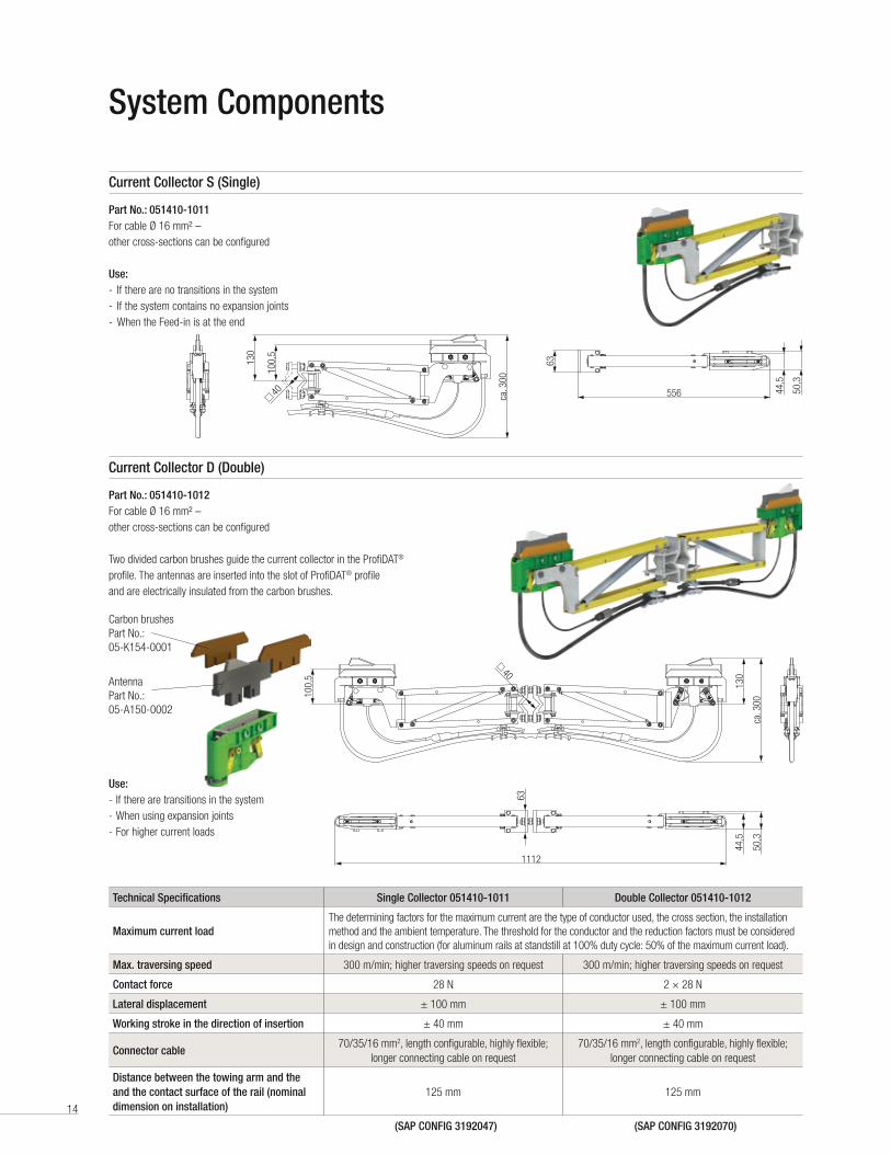
Hinge-Point Transition Element (for STS Cranes)
Part No.: 051413-01
The hinge-point transition element secures the data connection
between the folding and the fixed parts of the crane .
The hinge-point transition element is fastened to the support
structure by screw at the two fixing points .
Including cable: Ecoflex® 10
Length: 20 m
Diameter: 10 .2 mm
Impedance: 50 Ω Attenuation @ 1GHz/100 m: 14 .2 dB
Max. frequency: 6 GHz
Includes 2 × angled connectors
65775
109
321 321
System Components
Central Signal Feed-In
Part No.: 051415-04
To extend the maximum system length from 250 m to 500 m in one segment, a central feed-
in can be used instead of an end feed-in . In this case, the signal feed-in point or stationary
transceiver (access point) is positioned in the middle of the traversing range . In order to feed the
wireless signal from the transceiver into the ProfiDAT® profile, an expansion element is then used
to feed the signal in . This means that the expansion element, which is designed to compensate for
the temperature-dependent changes in the profile length, is performing two functions .
Including cable: Ecoflex® 10
Length: 2 × 10 m
Diameter: 10 .2 mm
Impedance: 50 Ω Attenuation @ 5GHz/100 m: 37 dB
Max. frequency: 6 GHz
Material: Aluminum, stainless steel
For system lengths greater than 250 m
Stationary transceiver
Comb filter Comb filter

19
System Components
Expansion Element (for E-RTG Cranes)
Part No.: 051416-01
The aluminum expansion element connects two ProfiDAT®
profiles together, compensating for changes in the length
of profiles due to temperature fluctuations .
Including cable: Ecoflex® 10
Cable length: 500/502/165 mm
Diameter: 10 .2 mm
Impedance: 50 Ω Attenuation @ 5GHz/100 m: 37 dB
Max. frequency: 6 GHz
Expansion: 0–45 mm
Includes 2 × angled connectors
Used for system lengths of 200 m or more
140,
5
149,1 547 22 80
Comb filter (2x) Comb filter Comb filter
Air gap
20
Total system length ≤ 200 m
...
Fastening point
Expansion element
100 m 100 mz1 EE
100 m 100 mz z2 EE
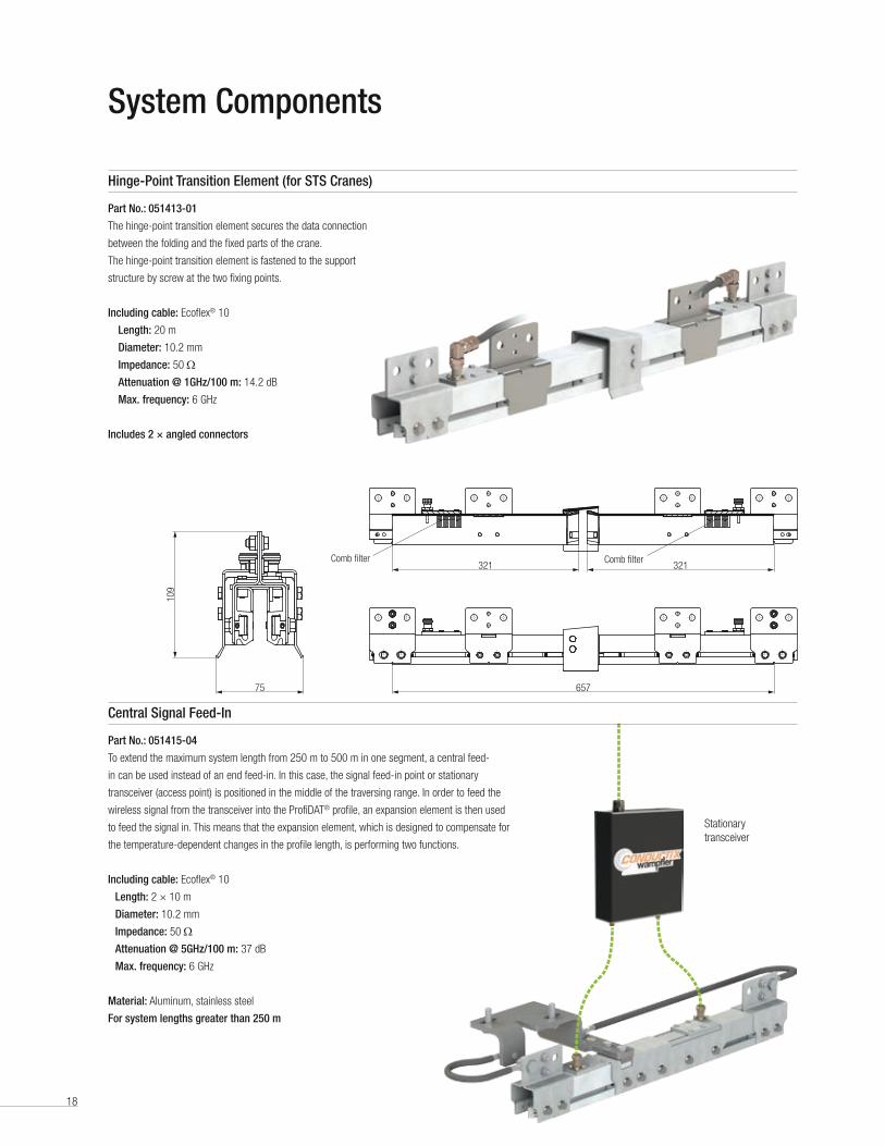
Diagram 1 – Open ends:
Gap:
G = L × t × α
L = t × αG
System ComponentsCalculating the Air Gap/Expansion Elements
Number of Expansion Elements (open end)
Maximum length: 500 m
Max. expansion possible for expansion element: 45 mm
Expansion coefficient of aluminum: 0 .0000238 1/K
Number of Expansion Elements
1 2 3 4 5 6 7 8 9 10 11 12 13 14 15 16Inter-medi-
atelength
[z]Total length of the conductor rail [m]
10 300 500 189
20 295 389 484 500 95
30 263 326 389 452 515 63
40 247 295 342 389 436 484 531 47
50 238 276 313 351 389 427 465 503 38
60 232 263 295 326 358 389 421 452 484 515 32
70 227 254 281 308 335 362 389 416 443 470 497 524 27
80 224 247 271 295 318 342 365 389 413 436 460 484 507 24
90 221 242 263 284 305 326 347 368 389 410 431 452 473 494 515 21
100 219 238 257 276 295 313 332 351 370 389 408 427 446 465 484 500 19
t tot
Determining the Air Gap
Number of Expansion Elements for Systems over 200 m
For conductor rail systems longer than 200 m, expansion elements must be placed at certain intervals in accordance with Diagrams 1 & 2 . Specific distances must be
observed for special systems and when the fixed point is located at the end of the system . Please contact us if you have a query .
-300 5 10 15 20 25 30 35 40 45
+10
+30
+50
+70
+90
+20
+40
+60
+80
+100+110
-20-10
0
Air gap [mm]
Ambi
ent t
empe
ratu
re d
urin
g in
stal
latio
n [°
C]
tmin
tmax
1
2
Instructions:
tmin
lowest temperature occurring in the given application
tmax
highest possible temperature in the given application
1 . Enter a tie line from tmin
to tmax
.
2 . Enter a horizontal line at the ambient temperature during installation .
3 . Drop a line down from the intersection of the two lines, and read off
the air gap to be installed .
Examples:
Temperature range: -15 °C to +85 °C
Ambient temperature during installation: +30 °C
Air gap: 25 mm
Temperature range: 0 °C to +60 °C
Ambient temperature during installation: +10 °C
Air gap: 37 mm
1
2

21
Diagram 2 – Limited ends/funnels
(minimum distance to limit = 50 m):
...
0 EEaa
FunnelFunnel
1 EEea
2 EEz ea
3 EEz z ea
Note
• No heating by the current load as this is a ground conductor rail
• Total systems lengths greater than 500 m only after consultation
System ComponentsCalculation of Expansion ElementsNumber of Expansion Elements (limited end/funnel)
Maximum length: 500 m
Max. expansion possible for expansion element: 45 mm
Max. expansion possible for funnel: 22 .5 mm
Expansion coefficient of aluminum: 0 .0000238 1/K
No. of expansion elements 0 1 2 3 4 5 6 7 8 9 10 Initiallength, a
Intermediate length, z
Endlength, eTotal length of the conductor rail [m]
10 189 195 295 395 495 95 100 100
20 95 147 242 336 431 500 47 95 100
30 63 126 189 252 315 378 441 500 32 63 95
40 47 95 142 189 236 284 331 378 425 473 520 24 47 71
50 38 76 113 151 189 227 265 303 340 378 416 19 38 57
60 32 63 95 126 158 189 221 252 284 315 347 16 32 47
70 27 54 81 108 135 162 189 216 243 270 297 14 27 41
80 24 47 71 95 118 142 165 189 213 236 260 12 24 35
90 21 42 63 84 105 126 147 168 189 210 231 11 21 32
100 19 38 57 76 95 113 132 151 170 189 208 9 19 28
t tot
Number of expansion elements 11 12 13 14 15 16 17 18 19 20 Initiallength, a
Intermediate length, z
Endlength, eTotal length of the conductor rail [m]
10 95 100 100
20 47 95 100
30 32 63 95
40 24 47 71
50 454 492 500 19 38 57
60 378 410 441 473 500 16 32 47
70 324 351 378 405 432 459 486 500 14 27 41
80 284 307 331 355 378 402 425 449 473 496 12 24 35
90 252 273 294 315 336 357 378 399 420 441 11 21 32
100 227 246 265 284 303 321 340 359 378 397 9 19 28
t tot

22
Electrical Interfaces
Mechanical Interface
Description of Interfaces
Maximum length of the feed cable 10 m
Profile length 5000 mm
Outer dimensions of the profile (width × height) 48 mm × 56 mm
Distance between poles 80 mm
Power supply: ProfiDAT® transceiver 24 V DC
Maximum data transmission rate 100 Mbit/s
Maximum traversing speed of the mobile transceiver 300 m/min
Interface 100 Mbit/s, RJ45 or LC
Permissible rated current for the conductor-rail system (L, N) 1000 A
Maximum suspension interval for hanger clamps 2 .5 m (for E-RTG: 3 m)
• Data interface
• Power supply/control voltage
• Power feed to conductor rails
• PE
• PE connector cable at the hinge point
Data interface:
ProfiDAT® 100 Mbit/s, RJ45 connection . At both ends of the ProfiDAT® system, customers must provide an RJ45 connector to connect the ProfiDAT® with their system .
- 1 × RJ45 socket
- TCP IP signal transmission (Ethernet protocol)
- PLC communication + safety-related control-signal communication
- Only data transmission of safety-related signals; additional safety equipment + controllers (PROFIsafe devices, etc .) are not included .
- Video/audio signals in digital Ethernet format
- Analog video signals converted into a digital format (by a multiplexer, for example)
PE interface:
The interface for the customer's grounding cable is located at the PE rail connector (Part No .: 051412-02) . At the flap (M10 drilled hole), the PE cable must be
connected according to the applicable standards .
Power supply / control voltage:
The controller of the ProfiDAT® data-transmission system requires the following power supply:
AC power supply for the feed-in control cabinet: 100–500 V, 50/60 Hz
DC control voltage for transceivers: 24 V
• Current collector
The current collector on the ProfiDAT® profile performs a dual function . Two divided carbon brushes guide the current collector in the ProfiDAT® profile .
The carbon brushes guarantee the connection to the ground cable (ProfiDAT® profile), while the two built-in antennas support the data transmission .
The antennas are inserted into the slot in the ProfiDAT® profile and are electrically isolated from the carbon brushes .

23
Description of Interfaces
Comb Filter
Central Feed-in
Ethernet
PROFINET
A Comb filter filters certain frequencies from signal groups .
This prevents the radio wave from escaping from the profile .
No interference with surrounding radio systems .
For system lengths greater than 250 m or when segmenting the data path, the signal is fed in over stretches or by central feed-in . To this end, the signal is fed through
an expansion element, in which case the maximum system length of the data path is 250 m per side .
“Industrial Ethernet” is the generic term for all efforts to make the Ethernet standard usable for networking devices used in industrial production . The characteristics of
pure Ethernet technology include the following points:
• Standardization according to IEEE 802 .3
• Transmission over a twisted-pair or fiber-optic cable
• Connectors for copper wiring: RJ45 (see Figure on the right)
• Maximum cable length of 100 m for twisted-pair cables
Industrial Ethernet encompasses many different protocols, of which the well-known PROFINET is only one .
PROFINET technology is used by Siemens and the ProfiBUS User Organization . It is the implementation of ProfiBUS for networking technology, bringing together the
advantages of Ethernet and the successful fieldbus . It is used for applications where fast data communication is required in combination with industrial IT functions .
Performance classes:
• TCP/IP: Open communication via Ethernet TCP/IP without real-time requirements
• RT: Real-time communication for I/O data transfer in automation technology
- Reaction times of up to 10 ms for time-critical applications
- RT data has a higher priority than TCP/IP data
• IRT: Isochronous real-time communication specifically for motion-control applications
- Reaction times < 1 ms for demanding time-critical applications, such as the control of drive axles
- IRT telegrams have their own time range in PROFINET communication, so there is no interference from standard communication
- Special hardware required
The specified connectors are the RJ45 connector for data and the M12 connector for electrical transmission over copper wires, and the LC connector for optical
transmission via optical fibers .
• ProfiSAFE defines safety-related automation tasks up to SIL3 (Safety Integrity Level 3) . It provides secure communication through a profile, i .e ., via a special user-data
format and a special protocol . PROFIsafe is specified in the IEC 61784-3 standard for PROFIBUS and PROFINET .
Industrial Ethernet protocolDirect transmission
Indirect transmission
EtherNet/IP ProfiBUS
PROFINET IO
Modbus TCP
Further protocols are possible after technical clarification.
Transmittable protocol types:

24
500 5003000
3000 5000 5000 5000
500050005000 475555
3000
x
3000 3000 3000 3000
80
130
125 19
0
808080
2500500
5000 5000
2500 2500
5000 5000
2500 25002500 2500
657
556
1112
500
111
297,4
49 50 50 50 49
464
Hanger Clamp
Feed-in/Feed-out Set
Hinge-Point Transition Element(only for STS Cranes)
Current Collector
Power Feed Hanger Clamp
Transceiver
Current Collector Rail Connector
System Layout E-RTG Crane
System Layout EOT/STS Crane
Current CollectorFront view
Connector

25
500 5003000
3000 5000 5000 5000
500050005000 475555
3000
x
3000 3000 3000 3000
80
130
125 19
0
808080
2500500
5000 5000
2500 2500
5000 5000
2500 25002500 2500
657
556
1112
500
111
297,4
49 50 50 50 49
464
Current Collector
Conductor rail running surface
Expansion Element
Current CollectorFront view
Current-Collecting TrolleyFront view

26
Example of the System Composition
Sample Order – Required Information for the Quotation
Part No.: Quantity Description Comment
051411-3512 30 ProfiDAT® conductor rail, PVC PE 5 m –
051414-03 62 ProfiDAT® hanger clamps Oversupply of two items
051412-01 15 ProfiDAT® connectorThe feed-in/feed-out set includes connectors (2 pcs), take into account the number of PE connectors
051412-02 13 ProfiDAT® PE connector Used every 25 meters
051415-01 1 Feed-in/feed-out set 0514 Use of end feed-in
051410-1011 1 ProfiDAT® S collector Since there is 1 consumer/traversing range without interruption
– 1 Transceiver access point, standard set Can be selected/customized to customer’s requirements
– 1 Transceiver client, standard set Can be selected/customized to customer’s needs requirements
– 1 Spare parts kit –
– 1 Commissioning –
Application: Data-transmission system for an automatic gantry crane
System length: 150 m
Number of systems: 1
Number of vehicles/systems: 1
Arrangement: Horizontal (opening facing down [required!])
Number of pins: 1 × data transmission including PE (replaces PE in the 0813 energy system)
Voltage: 400 V / 50 Hz
Feed: End Feed-in
Traversing speed: Approx . 60 m/min
Existing PLC system: SIEMENS S7-400
Protocol: Ethernet (TCP/IP; layer 2)
Bus system: PROFINET® & PROFIsafe
Interface: RJ45
Safety PLC integrated: Yes (on site)
Data to be transferred: Control-signal data (yes)
Safety-signal data (emergency stop, etc .)
Video signals; digital signals
(Analog signals are to be converted into the digital Ethernet format)
Audio signals (telephone, video, etc .)
Environmental conditions: Metal dust (scrap-metal shredder on adjacent site);
proximity to water (German inland port); grain dust
Ambient temperatures: Approx . -20 °C to approx . 45 °C
Energy supply: Yes, already installed (0813 series – 500 A – 150 m – 4-pin; 3 × PH+PE)
Fastening: Suggestion: fasten to structure already installed on site . Support interval: max . 2500 mm
Max. traversing speed: 5 m/s (300 m/min; 18 km/h) for ProfiDAT®
Cable length: 10 m transceiver to antenna; 10 m antenna cable

Conductix-Wampfler – the complete program
Other Products from Conductix-Wampfler
The products described in the this catalog represent a few of the products from the broad spectrum of Conductix-Wampfler components and systems for the transfer of energy, data, gases, and fluids . The solutions we deliver for your applications are based on your specific requirements . In many cases, a combination of several different Conductix-Wampfler products are needed to fill the application . You can count on all of Conductix-Wampfler’s business units for hands-on engineering support - coupled with the perfect solution to meet your energy management and control needs .
Spring balancers and retractors
ENDO spring balancers by Conductix-
Wampfler are rugged, reliable
high-precision positioning devices that
reduce operator fatigue and assist
with accurate tool placement .
Air hoists and balancers
ENDO Air hoists accurately place delicate loads and continuously vary the speed for precise positioning . They run cool in continuous operations .
Bumpers
Conductix-Wampfler offers a
complete range of bumpers for the
auto industry, cranes, and heavy
machinery . These include rubber,
rubber/metal, and cellular types .
Motor driven cable reels
Motor driven reels by Conductix-
Wampfler are the perfect solution
for managing long lengths of heavy
cable and hoses in very demanding
industrial applications . Monospiral,
level wind, and random wind spools .
Slip ring assemblies
Whenever powered machinery needs
to rotate 3600, field proven slip ring
assemblies by Conductix-Wampfler
can flawlessly transfer energy and
data . Here, everything revolves
around flexibility and reliability .
Radio remote controls
Safe, secure, and reliable radios
use the latest in microprocessor
technology . Available in several
models for overhead crane control
and other types of machinery .
Cable Festoon systems
It‘s hard to imagine Conductix-
Wampfler cable trolleys not being
used in virtually every industrial
application . They are reliable and
robust and available in an enormous
variety of sizes and models .
Conductor bar
Whether they are enclosed conductor
rails, expandable single-pole bar
systems, or high amperage bar
for demanding steel mill use up to
6000 amps . Conductix-Wampfler‘s
conductor bar is the proven solution
to reliably move people and material .
Push Button Pendants
Our ergonomic pendants are
ideally suited for industrial control
applications . They are available in
a wide range of configurations for
overhead cranes and other machinery .
Inductive Power Transfer IPT®
The contact-less system for
transferring energy and data . For all
tasks that depend on high speeds
and absolute resistance to wear .
Spring driven cable reels
We have 60 years experience and
trusted brands such as Insul-8,
Wampfler, and IER . We offer small
cord reels all the way to large
multi-motor units, a wide range of
accessories, and hazardous location
reels .
Energy guiding chains
The “Jack of all Trades“ when it comes
to managing energy and data cables
and air and fluid hoses . A wide range of
energy guiding chains are available for
many industrial applications .

Contact us for our Global Sales Offices
www.conductix.us
KAT0
514-
0001
-US
USA / LATIN AMERICA
10102 F Street
Omaha, NE 68127
Customer Support
Phone +1-800-521-4888
Fax +1-800-780-8329
Phone +1-402-339-9300
Fax +1-402-339-9627
info .us@conductix .com
latinamerica@conductix .com
CANADA
18450 J .A . Bombardier
Mirabel, QC J7J 0H5
Customer Support
Phone +1-800-667-2487
Phone +1-450-565-9900
Fax +1-450-851-8591
info .ca@conductix .com
MÉXICO
Calle Treviño 983-C
Zona Centro
Apodaca, NL México 66600
Customer Support
Phone (+52 81) 1090 9519
(+52 81) 1090 9025
(+52 81) 1090 9013
Fax (+52 81) 1090 9014
info .mx@conductix .com
BRAZIL
Rua Luiz Pionti, 110
Vila Progresso
Itu, São Paulo, Brasil
CEP: 13313-534
Customer Support
Phone (+55 11) 4813 7330
Fax (+55 11) 4813 7357
info .br@conductix .com
© C
ondu
ctix-
Wam
pfler
| 20
16 |
Subj
ect t
o Te
chni
cal M
odifi
catio
ns W
ithou
t Prio
r Not
ice