Embed Size (px)
Citation preview

PRO 24S / 24SF / 28LE / 28LET / 28LE2FUSER GUIDE
25108-01A
25108-01A
i
Limited Lifetime Warranty
SUNVISION® warrants your tanning unit to be free of structural defects in its material andworkmanship, under normal use, for its lifetime. SUNVISION will repair or replace, at their
discretion, any defect to the structure which affects the performance of the unit.
For 6 months from the date of purchase, SUNVISION will provide replacements for partsthat prove to be defective in material or workmanship. Acrylic shields, fluorescent lamps,and lamp starters are excluded from this warranty. Labor will be covered for 30 days from
purchase date. Normal wear, damage from misuse or abuse, damage incurred in transit, ordamage done by unauthorized repairs or modifications are not covered by this warranty.
ETS, Inc. disclaims any implied warranty of merchantability or fitness for any periodbeyond the expressed warranty. Some states do not allow limitations on how long an
implied warranty lasts, so the above limitations may not apply to you.
No one has authority to change or modify this Limited Lifetime Warranty in any respect. Toobtain service under the Limited Lifetime Warranty, contact ETS, Inc. at 1-800-449-3605,
and ask for the Technical Service Department.
ETS, Inc. shall not be liable for loss of use, loss of time , inconvenience, rental or substituteproducts, loss of business, loss of income, or any other incidental or consequential damages.Some states do not allow the exclusion or limitation of incidental or consequential damages,
so the above limitation or exclusion may not apply to you.
This warranty gives you specific legal rights, and you may also have other rights which mayvary from state to state.
All warranty service must be performed by an authorized service person. If your tanningunit must be returned for service, all freight charges must be at your expense. Contact yourplace of purchase for the address of the SUNVISION Service Center nearest you. Proof of
purchase is required to obtain warranty service.
This warranty covers the original purchaser only. This warranty is void if the unit is modi-fied in any manner from its original design.

ii
elcome
2510
8-01
A
Congratulations on your purchase of this technologically advanced sun tanning unit. It has beendesigned to provide years of dependable service for you.
Please read all the instructions in this booklet before installing and using the unit. Always be sure toobserve all safety precautions.
ontentsSafety Information . . . . . . . . . . . . . . . . . . . . . . . . . . . . . . . . . . . . . . . .iii
Installation . . . . . . . . . . . . . . . . . . . . . . . . . . . . . . . . . . . . . . . . . . . . . .1Unpacking and Inspection . . . . . . . . . . . . . . . . . . . . . . . . . . . . . .1Tools Required . . . . . . . . . . . . . . . . . . . . . . . . . . . . . . . . . . . . . .1Pre-Installation Planning . . . . . . . . . . . . . . . . . . . . . . . . . . . . . . .2Assembly Procedures . . . . . . . . . . . . . . . . . . . . . . . . . . . . . . . . . .3Making Electrical Connections . . . . . . . . . . . . . . . . . . . . . . . . . .10Remote Connections . . . . . . . . . . . . . . . . . . . . . . . . . . . . . . . . .11
Operation . . . . . . . . . . . . . . . . . . . . . . . . . . . . . . . . . . . . . . . . . . . . .14Before You Tan . . . . . . . . . . . . . . . . . . . . . . . . . . . . . . . . . . . . . .14Exposure Times . . . . . . . . . . . . . . . . . . . . . . . . . . . . . . . . . . . . .14Using Your Sunbed . . . . . . . . . . . . . . . . . . . . . . . . . . . . . . . . . .15
Care and Maintenance . . . . . . . . . . . . . . . . . . . . . . . . . . . . . . . . . . . .17Cleaning After Use . . . . . . . . . . . . . . . . . . . . . . . . . . . . . . . . . . .17Thorough Periodic Cleaning . . . . . . . . . . . . . . . . . . . . . . . . . . . .17Hour Counter . . . . . . . . . . . . . . . . . . . . . . . . . . . . . . . . . . . . . .18Mechanical Inspection . . . . . . . . . . . . . . . . . . . . . . . . . . . . . . . .18Replacing Lamps . . . . . . . . . . . . . . . . . . . . . . . . . . . . . . . . . . . .19
Troubleshooting . . . . . . . . . . . . . . . . . . . . . . . . . . . . . . . . . . . . . . . . .22
Obtaining Service . . . . . . . . . . . . . . . . . . . . . . . . . . . . . . . . .back cover

iii
25108-01A
afety InformationUltraviolet radiation. Follow instructions. Avoid overexposure. As with natural sunlight, overexposure can causeeye and skin injury and allergic reactions. Repeated exposure may cause premature aging of the skin and skin
cancer. WEAR PROTECTIVE EYEWEAR; FAILURE TO MAY RESULT IN SEVERE BURNS OR LONGTERM INJURY TO THE EYES.Medications or cosmetics may increase your sensitivity to the ultraviolet radiation. Consult physician before using sunlamp if you areusing medications or have a history of skin problems or believe yourself especially sensitive to sunlight. If you do not tan in the sun, youare unlikely to tan from the use of this product. Children, the elderly, or fair skinned people who always burn easily and either never tanor tan minimally should not use this equipment.
To use, lie down under canopy and pull down as far as adjustment will allow. 28LE series: Maintain at least 1 inch (2.5 centimeters) betweenyour body and canopy clear plastic panel, otherwise overexposure may occur. 24S series: Minimum use distance from face tanner is 1 inch(2.5 centimeters). All: Minimum use distance elsewhere is touching the clear plastic panels. Do not use without clear plastic panels in place.Untanned persons should not tan on consecutive days during their first week of tanning. Never tan more than once a day. Tanning normal-ly appears after the first few sessions and maximizes after approximately four weeks. Tan once or twice per week thereafter to maintainappearance. Persons already having a base tan may begin at advanced levels corresponding to the extent of their base tan.
New lamps emit approximately 10% more ultraviolet radiation during the first 50 hours of operation. Recommended tanning times shouldtherefore be reduced by approximately 10% during that period.
WARNING: • Read the instructions booklet before using this sunlamp product. • All persons in the room should wear protective eyewearwhen lamps are on. Recommended eyewear: provided eyeshields or equivalent eyewear as defined under 21 CFR 1040.20. Other typesof eyewear may not provide adequate protection. Failure to use protective eyewear may result in severe burns or other eye injury. If dis-comfort develops, discontinue use and consult a physician.
THE FOLLOWING LAMPS HAVE BEEN CERTIFIED FOR USE IN THE 24S AND 28LE MODEL SERIES:
GOLDEN TAN™ Wolff® Model GT71-T12-100W BI-PIN or Velocity® Wolff® Model VEL 71-T12-100W (Full length lamps)GOLDEN TAN™ Wolff® Model GT59-T12-80W BI-PIN or Velocity® Wolff® Model VEL 59-T12-080W (Short lamps in 24SF)Turbo Sun® S Wolff® Model F8-T5-10W (Turbo lamps in 28LET)Heraeus E400 HPT, Philips Model HPA 400/30s or CosmoTech Model 23045 (Facial Unit Lamps in 24SF and 28LE2F)
CAUTION: To achieve compliance with Canadian Standards Association’s (CSA) standard CAN/CSA C22.2 No.224, connect only to a circuit protected by a Class A Ground Fault Circuit Interrupter.
This product is in conformity with performance standards for sun lamp products under 21 CFR PART 1040.20 andANSI/UL Standard 482. Certified to CAN/CSA Standard C22.2 NO. 224.
DANGER
RECOMMENDED EXPOSURE TIMES IN MINUTES MAXIMUM EXPOSURE TIME IS 20 MINUTESLevel 1/Week 1 Level 2 Level 3 Level 4 Subsequent
Skin Type: 1st-3rd Sessions MaximumI Sensitive Skin (Burns easily and severely and does not tan.) NOT RECOMMENDED FOR TANNINGII Light (Burns easily and severely and tans minimally.) 4 8 12 16 20III Normal (Burns moderately and tans average.) 6 10 15 20 20IV Dark (Burns minimally, tans easily and above average.) 8 12 16 20 20
DISCONNECT POWER CORD BEFORE ATTEMPTING TO CLEAN, RELAMP, OR ENGAGE IN THE MAINTENANCE OF THIS PRODUCT.
88465

iv
2510
8-01
A
Safety InformationRayonnement ultraviolet. Veuillez suivre les instructions. Évitez une exposition excessive : tout comme pour lesrayons du soleil, une exposition excessive peut causer des blessures aux yeux et à la peau et provoquer des
réactions allergiques. Une exposition répétée peut causer le vieillissement prématuré de la peau et provoquer le cancer de la peau.PORTEZ DES LUNETTES PROTECTRICES: LE NON-RESPECT DE CETTE CONSIGNE DE SÉCURITÉ PEUT ENTRAÎNER DEGRAVES BRÛLURES OU DES LÉSIONS OCULAIRES À LONG TERME. Les médicaments ou les produits cosmétiques peuvent aug-menter votre sensibilité au rayonnement ultraviolet. Consultez un médecin avant d’utiliser la lampe solaire si vous prenez des médica-ments, si vous souffrez d’une maladie cutanée ou si vous croyez être particulièrement sensible aux rayons du soleil. Si vous ne bronzezpas au soleil, il est peu probable que vous bronzerez sous une lampe solaire. Les enfants, les personnes âgées et les personnes qui ontune peau claire qui brûle facilement, ne bronze jamais ou alors très peu, ne devraient pas utiliser cette lampe.
Étendez-vous sous la partie supérieure, puis abaissez celle-ci aussi bas que possible; 28LE: en veillant cependant à conserver unespace d’au moins 1 pouce (2,5 centimètres) entre le corps et le panneau de plastique transparent de la partie supérieure, afin d’éviterune exposition excessive. 24S: La distance minimale d’usage de l’appareil de bronzage pour le visage (s’il y en a un) est de 1 pouce(2,5 centimètres). Les autres parties du corps peuvent toucher les panneaux de plastique transparents. N’utilisez pas la lampe sans lespanneaux de plastique transparents. La première semaine de bronzage, les personnes qui n’ont pas un hâle initial ne doivent pas sefaire bronzer tous les jours. Ne vous faites jamais bronzer plus d’une fois par jour. Le bronzage commence normalement à apparaîtreaprès les premières séances : il atteint son apogée au bout d’environ quatre semaines. Les personnes qui ont déjà un teint hâlé peu-vent commencer à des niveaux plus élevés, selon l’importance de leur hâle initial.
Les lampes neuves émettent approximativement 10 % de plus de rayons ultraviolets au cours des 50 premières heures de fonction-nement. Le temps de bronzage doit donc êatre réduit d’environ 10 % pendant cette période.
AVERTISSEMENT : • Lisez le livret d’instructions avant d’utiliser cette lampe solaire. • Les autres personnes présentes dans la piècedoivent aussi porter des lunettes protectrices lorsque les lampes sont allumées. Coquilles de protection pour les yeux recommandées :Les coquilles de protection fournies ou l’équivalent, tel que le stipule le document 21 CFR 1040.20. Les autres types de lunettes pro-tectrices peuvent ne pas assurer une protection adéquate. Utilisé sans lunettes protectrices, ce produit peut causer des brûlures oulésions oculaires graves. Si vous souffrez d’un malaise, arrêtez l’utilisation et consultez un médecin.
SEULES LES LAMPES SUIVANTES ONT ÉTÉ HOMOLOGUÉES POUR CET ÉQUIPEMENT :GOLDEN TAN™ Wolff® Model GT71-T12-100W BI-PIN ou Velocity® Wolff® Modèle VEL 71-T12-100WGOLDEN TAN™ Wolff® Model GT59-T12-80W BI-PIN ou Velocity® Wolff® Modèle VEL 59-T12-080W (24SF)Turbo Sun® S Wolff® Modèle F8-T5-10W (lampes turbo : 28LET)Heraeus E400 HPT, Philips Modèle HPA 400/30s ou CosmoTech Modèle 23045 (unité faciale : 24SF, 28LE)
ATTENTION: Pour Répondre à la norme CAN/CSA C22.2 No 224 de L’Association Canadienne de Normalisation(CSA) , brancher seulement à une dérivation protégée par un disjoncteur différentiel de Classe A.
Ce produit est conforme aux normes de rendement pour les lampes solaires dans le documents 21 CFR, partie1040.20 , ANSI/UL 482 , CAN/CSA C22.2 N° 224.
ATTENTION: Débranchez le cordon d’alimentation avant de nettoyer l’appareil, d’en faire l’entretien ou de changer les lampes.
TEMPS D’EXPOSITION RECOMMANDÉ EN MINUTES LE TEMPS D’EXPOSITION MAXIMAL EST DE 20 MINUTESÉlevé 1/Semaine 1 Élevé 2 Élevé 3 Élevé 4 Sem. suivantes
Type de peau: 1ere-3e Temps maximal
I Peau sensible (brûle facilement et ne bronze pas) NON RECOMMANDÉ
II Peau claire (brûle facilement et bronze très peu) 4 8 12 16 20
III Peau normale (brûle et bronze de façon modérée) 6 10 15 20 20
IV Peau foncée (brûle très peu, bronze plus facilement que la moyenne) 8 12 16 20 20
88465
DANGER

1
25108-01A
Tools RequiredYou will need the following tools toassemble your sunbed.
Utility Knife
Phillips Screwdriver
Allen Wrench(Supplied in hardware kit)
Unpacking and Inspection
Your sunbed comes in two cardboard car-tons, one for the bench and one for thecanopy. Open the cartons and remove thebench and canopy as follows.
The bench and canopy are each wrappedin plastic. Pull back the plastic and, witha helper, grasp the bench and pull it fromthe carton bottom, leaving the plasticwrap and the carton packaging. Do thesame for the canopy. Do not try to lifteither unit with the plastic still on as itmay slip.
Note! The cartons are reusable. You maywish to save them for future use.
The canopy box also contains a pair of gassprings. The bench box also contains thefront and side skirts with mountingscrews, a box containing necessary assem-bly hardware, safety goggles, and pillow,and a box containing two stand legs.
Inspect these items, including the canopyand bench, and make sure they are freefrom any visible damage. Report theextent of any damage to the transportationcompany.
Record the serial numbers of the canopyand bench in the area provided at theback of this manual. This information willbe required whenever you call customerservice.
nstallation
Proper assembly of your sunbed requiresthree people. Plan to have a couple ofhelpers assist you.
CAUTION

2
Installation - Pre-Installation Planning
2510
8-01
A
Pre-Installation PlanningBefore you begin to assemble your sunbed, you should observe the following pre-installation considerations.
Your sunbed operates from a 220V ACsource. The Pro 24S series tanning bedsrequire a NEMA 6-20R electrical outlet(below) on a dedicated circuit capable ofproviding 20 Amp service installed in theroom in which you will use the unit. ThePro 28LE series requires a NEMA L6-30Relectrical outlet (below, right) on a dedi-cated circuit capable of providing 30 Ampservice installed in the room in which youwill use the unit. We recommend installa-tion by a professional electrician. The out-let must be earth grounded.
30 AMP NEMA #L6-30R RECEPTACLE (28LE series)
To achieve compliance with CanadianStandards Association’s (CSA) standardCAN/CSA C22.2 No. 224, connect only to acircuit protected by a Class A Ground FaultCircuit Interrupter.
CAUTION
WARNINGShock hazard.Disconnect power before servicing.
Air from the room is used to cool the sunbed.Maximum ambient room temperature shouldbe 80°F. Place your sunbed no closer than 6”from any wall. Make sure nothing obstructsthe airflow into the sunbed’s endcaps or outof the fan openings. A poorly ventilated roommay cause the unit to become hot and causediscomfort to the user.
CAUTION
Use of a voltage source above 230V AC mayprevent proper operation of the sunbed andcould cause damage and void the warranty.
CAUTION
20 AMP NEMA #6-20R RECEPTACLE (24S series)

3
Installation - Assembly Procedures
25108-01A
Assembly ProceduresHardware Inventory
Use the utility knife to cut open the hard-ware box and remove the small bag ofhardware. In addition to a small Allenwrench and pillow, make sure you havethe following hardware items.
Allen-head Bolt5/16” x 1”Quantity 2
5/16” Metal WasherQuantity 2
BushingQuantity 2
Allen-head Bolt5/16” x 1 1/2”
Quantity 2
Nylon WasherQuantity 2
Hinge BracketsQuantity 2
(left and right)
Safety GogglesQuantity 1
WARNINGWear protective eyewear.Failure to may result in severe burns orlongterm injury to the eyes.
4
Installation - Assembly Procedures
2510
8-01
A
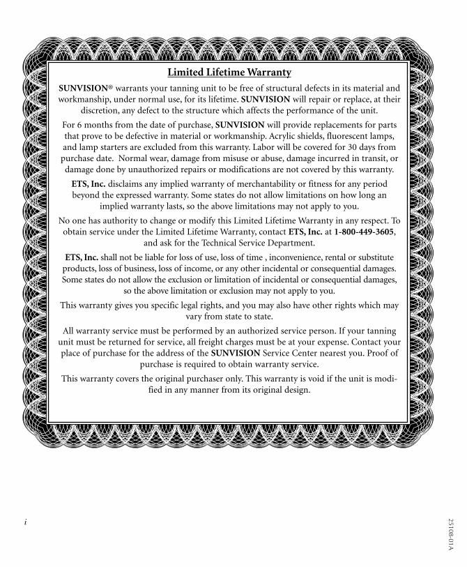
Attaching Legs to BenchLay the bench upside down on the floor.Locate the two stand legs and attach to thebench as shown below.
1. Using six 5/16” x 1” bolts and the sixlarger 5/16” washers (pre-installed),attach the stand legs with the skirtmounting holes toward the back ofthe bench as shown. Install centerbolt first. You may have to gentlypush sides of legs in to align holes.Tighten with the Allen wrench.
(ELECTRICAL CONNECTOR INDICATES BACKOF BENCH)
SKIRT MOUNTING HOLES

5
Installation - Assembly Procedures
25108-01A
Assembling Skirt on 24S series(for 28LE series, see next page)
1. Position the side skirts at either end ofthe base. Install two #8 x 1/2” screws(packaged with the skirt kit) through thepre-drilled holes of the side skirt into theback of the leg support. Repeat for theother side skirt.
2. Turn the bed around and put the frontskirt in place, making sure the ends wrapover the side skirts and the velcro padsgrab at each end.
(BACK OF BED SHOWN)
(FRONT OF BED SHOWN)
Install screws here
6
Installation - Assembly Procedures
2510
8-01
A
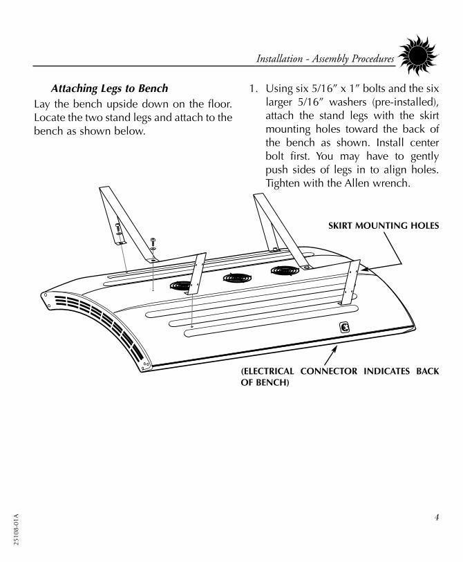
Assembling Skirt on 28LE series(for 24S series, see previous page)
1. Position the side skirts at either end ofthe base. Install two #8 x 1/2” screwsthrough the pre-drilled holes of the sideskirt into the back of the leg support.Repeat for the other side skirt.
2. Turn the bed around and put the frontskirt in place, making sure the ends wrapover the side skirts. Secure it in place withtwo #8 x 1/2” screwsin each end.
(BACK OF BED SHOWN)
(FRONT OF BED SHOWN)
Install screws here
7
Installation - Assembly Procedures
25108-01A
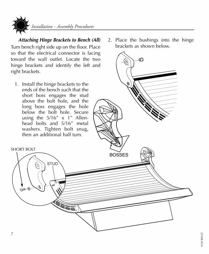
Attaching Hinge Brackets to Bench (All)Turn bench right side up on the floor. Placeso that the electrical connector is facingtoward the wall outlet. Locate the twohinge brackets and identify the left andright brackets.
2. Place the bushings into the hingebrackets as shown below.
1. Install the hinge brackets to theends of the bench such that theshort boss engages the studabove the bolt hole, and thelong boss engages the holebelow the bolt hole. Secureusing the 5/16” x 1” Allen-head bolts and 5/16” metalwashers. Tighten bolt snug,then an additional half turn.
SHORT BOLT

2510
8-01
A 8
Installation - Assembly Procedures
Attaching Canopy to Bench1. Lift the canopy and hold it between
the hinge brackets. You may want touse some of the cardboard packing,laid across the bench, to support thecanopy.
2. Insert the 5/16” x 1 1/2” bolts withthe nylon washers into both hingebrackets. Tighten bolts into the end-cap threaded inserts until snug, thenan additional half turn. Do not over-tighten to avoid damaging threadedinserts.

25108-01A
9
Installation - Assembly Procedures
Attaching Gas Springs1. The gas springs are shipped with
locking clips installed. Use a screw-driver to pry back the locking clipson the gas springs as they areinstalled. (See right)
2. With a helper holding the canopyopen, align open ends of gas springball joints with pivot studs and pushinto place. Be sure rod end is down asshown. DO NOT lower canopy untilboth gas springs are engaged!
3. Lift and lower canopy a few times tolubricate gas springs for optimumperformance.
PIVOT STUD
LOCKING CLIP
BALL JOINT
SCREWDRIVER
CAUTIONFailure to engage locking clips mayresult in the ball joints working loose,allowing the canopy to fall, which mayresult in damage to the unit and injury.

2510
8-01
A 10
Installation - Making Electrical Connections
1. Your sunbed is designed to communicate withremote control devices. The remote control isoptional and is not includedwith your sunbed.If you choosenot to use aremote con-trol, the RemoteControl BypassPlug must beplugged into eitherRemote Port as shown. (Theunit is shipped with the RemoteControl Bypass Plug installed.) Yoursunbed will not operate without either thebypass plug or a remote system connected. Ifremote operation is desired, see RemoteConnections.
2. Connect the canopy to bench power cord to thebench receptacle. The plug is polarized. Alignthe terminals and firmly push on until seatedthen tighten the threaded locking ring.
3. Plug the three-prong 220V AC power cord into adedicated outlet (see Pre-Installation Planning).
Making Electrical Connections
THREADED LOCKING RING
CANOPY POWER CORD
RECEPTACLEON BENCH
ELECTRICAL PANEL
WARNINGShock hazard.Be sure AC power is disconnectedbefore connecting cables.

25108-01A
11
Installation - Remote Connections
Remote Connections
Your sunbed incorporates advanced circuitryallowing it to connect and communicate withmost remote control systems. If a remote sys-tem is to be used, first determine whether theremote system is a T-Max® System or a stan-dard remote system operating with a controlrelay. Follow the appropriate instructions foryour system type.
T-Max® ProductsThe T-Max® remote systems offer the ultimatein sunbed control, while allowing the tannereasy straightforward operation. Your sunbed isconfigured to directly connect to this system.The circuitry inside your sunbed eliminates theneed for the T-Max® 1A or 3A when connect-ing to the T-Max® Manager series. Yoursunbed supports the auto addressing feature ofthe latest T-Max® Manager models and the fol-lowing parameters: 5, 6, 7, 8, 9, and 15. Seeyour T-Max® manual for descriptions of theseparameters and how they function.
T-Max® Manager Remote System This system is ideal for multiple sunbed instal-lations. Simply connect the RJ-22 modularcable(s), described in the T-Max® Managermanual, into the remote port(s) located on theback of your sunbed and follow the instruc-tions that came with your remote system, not-ing figure 1. If you have an older T-Max®Manager that doesn’t support auto addressing,set the address of each sunbed manually asdescribed in Setting the address manually.
You can place your sunbed at any loca-tion in the series.
figure 1
NOTE: A T-Max® 1Acan be substituted for
the 3A in figure 1.
The remote connection is not designed tosupply or accept high voltage, nor can itprovide power to an external timer. Thesunbed’s remote interface circuitry oper-ates on 5 volts, attempting to connect it toany higher voltages will damage thesunbed as well as void your warranty.
CAUTION
12
Installation - Remote Connections
2510
8-01
A
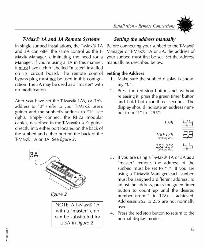
T-Max® 1A and 3A Remote SystemsIn single sunbed installations, the T-Max® 1Aand 3A can offer the same control as the T-Max® Manager, eliminating the need for aManager. If you’re using a 1A in this manner,it must have a chip labelled “master” installedon its circuit board. The remote controlbypass plug must not be used in this configu-ration. The 3A may be used as a “master” withno modification.
After you have set the T-Max® 1A’s, or 3A’s,address to “0” (refer to your T-Max® user’sguide) and the sunbed’s address to “1” (seeright), simply connect the RJ-22 modularcables, described in the T-Max® user’s guide,directly into either port located on the back ofthe sunbed and either port on the back of theT-Max® 1A or 3A. See figure 2.
Setting the address manuallyBefore connecting your sunbed to the T-Max®Manager or T-Max® 1A or 3A, the address ofyour sunbed must first be set. Set the addressmanually as described below.
Setting the Address 1. Make sure the sunbed display is show-
ing “0”.2. Press the red stop button and, without
releasing it, press the green timer buttonand hold both for three seconds. Thedisplay should indicate an address num-ber from “1” to “255”.
3. If you are using a T-Max® 1A or 3A as a“master” remote, the address of thesunbed must be set to “1”. If you areusing a T-Max® Manager each sunbedmust be assigned a different address. Toadjust the address, press the green timerbutton to count up until the desirednumber (from 1 to 128) is achieved.Addresses 252 to 255 are not normallyused.
4. Press the red stop button to return to thenormal display mode.
NOTE: A T-Max® 1Awith a “master” chipcan be substituted for
a 3A in figure 2.
1-99
100-128(blinking dot)
252-255(blinking dot)
figure 2

13
Installation - Remote Connections
25108-01A
figure 3
Remote systems using a Control Relay
Most non-T-Max® remote systems control thesunbed by the use of a relay. The relay oper-ates the sunbed by connecting and discon-necting a pair of wires leading from thesunbed. Refer to the user’s manual providedwith your remote system to determine if itoperates in this way. To connect your sunbedto this type of system a remote interface kit isrequired. Contact your place of purchase toobtain the kit. Figure 3 details a typical con-nection. Follow the instructions provided withthe kit and from the remote’s manual to makethe necessary connections.
The remote connection is not designed tosupply or accept high voltage, nor can itprovide power to an external timer. Thesunbed’s remote interface circuitry oper-ates on 5 volts, attempting to connect it toany higher voltages will damage thesunbed as well as void your warranty.
CAUTION
14
2510
8-01
A
peration
Before You Tan
Before using your sunbed, please note thefollowing important precautions.
• Your skin should be free of cosmetics,oils, or other body lotions prior to tan-ning except for those specificallymade for use with tanning devices.Your hair should be free of gels,mousses, sprays, or other hair productsprior to tanning. These products cancause damage to the sunbed acrylic.As an alternative, a shower cap ortowel can be worn to keep treated hairaway from the sunbed surfaces.
• Natural body oils aid in moisturizingthe skin. Try not to bathe or showerimmediately before tanning.
Exposure Times
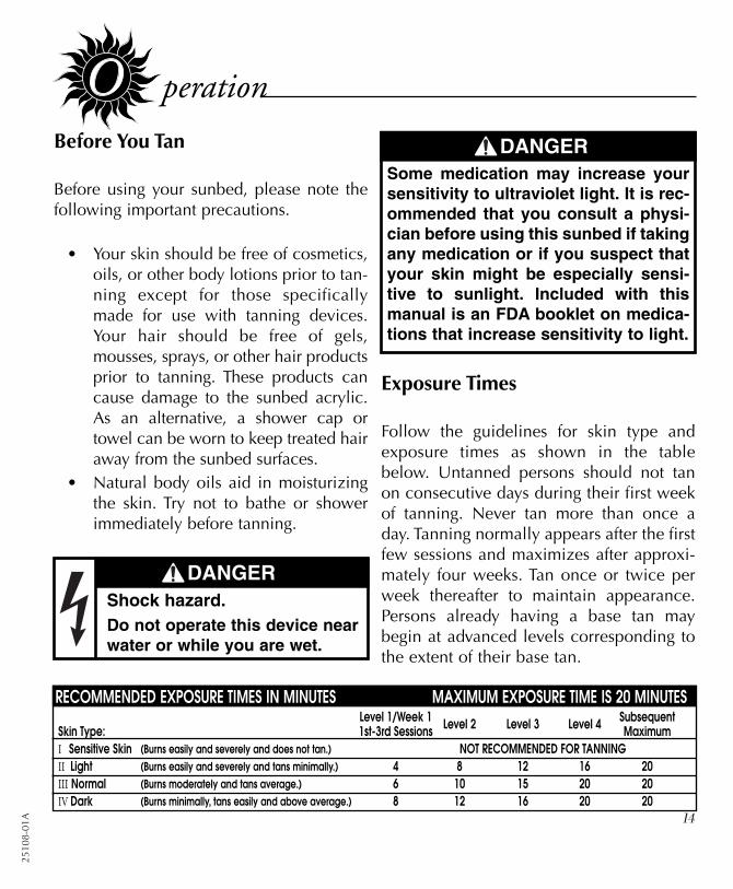
Follow the guidelines for skin type andexposure times as shown in the tablebelow. Untanned persons should not tanon consecutive days during their first weekof tanning. Never tan more than once aday. Tanning normally appears after the firstfew sessions and maximizes after approxi-mately four weeks. Tan once or twice perweek thereafter to maintain appearance.Persons already having a base tan maybegin at advanced levels corresponding tothe extent of their base tan.
RECOMMENDED EXPOSURE TIMES IN MINUTES MAXIMUM EXPOSURE TIME IS 20 MINUTESLevel 1/Week 1 Level 2 Level 3 Level 4 Subsequent
Skin Type: 1st-3rd Sessions MaximumI Sensitive Skin (Burns easily and severely and does not tan.) NOT RECOMMENDED FOR TANNINGII Light (Burns easily and severely and tans minimally.) 4 8 12 16 20III Normal (Burns moderately and tans average.) 6 10 15 20 20IV Dark (Burns minimally, tans easily and above average.) 8 12 16 20 20
DANGERShock hazard.Do not operate this device nearwater or while you are wet.
DANGERSome medication may increase yoursensitivity to ultraviolet light. It is rec-ommended that you consult a physi-cian before using this sunbed if takingany medication or if you suspect thatyour skin might be especially sensi-tive to sunlight. Included with thismanual is an FDA booklet on medica-tions that increase sensitivity to light.

15
Operation - Using Your Sunbed
25108-01A
WARNINGWear protective eyewear.Failure to may result in severe burns orlongterm injury to the eyes.
A
B
C
D
2. Lift the canopy, lie down on the bench(face up), lower the canopy toward yourbody. For best results, position the canopyas close to your body as possible, whilemaintaining minimum distances (seeSafety Information).
3. When the timer reaches “0” the lamps turnoff. If you want to stop your session beforetime expires, press the stop button (C).
4. Raise the canopy by using the outer edgeof the canopy, do not push up on theacrylic shield as it may crack. The coolingfans run for three minutes after the lampsshut off to aid in cooling the sunbed. Thetimer will indicate “..” as a reminder toclean the sunbed. After the sunbed iscleaned press the timer button and thedisplay will return to “0”.
Using Your Sunbed(When connected to the T-Max® Manager or T-Max® 1A or 3A.)
A Timer display - Displays remaining time.
B Timer button - Turns bed on. Timer dis-play shows remaining time. If a lessertime is desired, press timer button untildesired time is displayed.
C Stop button - Interrupts tanning session.
D Face tanner switch - (Units equippedwith facial units only.) Turns face tanner,or turbo lamps, on (|) and off (O).
1. If the remote system has been set to allowa pre-tanning delay time, the timer display(A) will repeatedly flash the delay symbol“dL” and then the remaining delay time.Press the timer button (B) or wait until thedelay time has expired to begin the tanningsession. The lamps will turn on and thetimer will begin to count down. If a tan-ning time less than the displayed time isdesired repeatedly press the timer button(B) to decrease the remaining time.

2510
8-01
A
Operation - Using Your Sunbed
16
A
B
C
D
Using Your Sunbed(When used as a stand alone unit or when connectedto a remote system using a control relay.)
A Timer display - Displays remaining time.
B Timer button - Turns bed on. Timer dis-play shows remaining time. If a lessertime is desired, press timer button untildesired time is displayed.
C Stop button - Interrupts tanning session.
D Face tanner switch - (Units equippedwith facial units only.) Turns face tanner,or turbo lamps, on (|) and off (O).
1. Press the timer button (B) to begin the tan-ning session. The lamps will turn on andthe timer will begin to count down fromthe maximum tanning session time. If atanning time less than the displayed timeis desired repeatedly press the timer but-ton (B) to decrease the remaining time.
2. Lift the canopy, lie down on the bench(face up), lower the canopy toward yourbody. For best results, position the canopyas close to your body as possible, whilemaintaining minimum distances (seeSafety Information).
3. When the timer reaches “0” the lamps turnoff. If you want to stop your session beforetime expires, press the stop button (C).
4. Raise the canopy by using the outer edgeof the canopy, do not push up on theacrylic shield as it may crack. The coolingfans run for three minutes after the lampsshut off to aid in cooling the sunbed.
WARNINGWear protective eyewear.Failure to may result in severe burns orlongterm injury to the eyes.
25108-01A
17
are and Maintenance
Cleaning After Use
Clean and disinfect your tanning bed’sbench and canopy after each use. Use anon-abrasive disinfectant cleaner that doesnot contain ammonia or ammonia deriva-tives. Ammonia may damage the acrylicshields. Spray the acrylic lightly with disin-fectant and wipe dry with a clean soft cloth.We recommend SunQuest® disinfectant andSunQuest® acrylic cleaner.
Thorough Periodic Cleaning
IntroductionThe cooling fans draw air through the bedand over time will cause a dust buildup onthe lamps and reflectors. This will reducethe tanning effectiveness of the bed. Whena dust buildup is observed, it is necessary tothoroughly clean the inside of the benchand canopy.
Cleaning the Canopy and BenchStep 1 Remove the acrylic shields and
lamps as described in ReplacingLamps.
Step 2 With a soft cloth, wipe the entirelength of each lamp to removeany film buildup.
Step 3 Clean both sides of the acrylicshields with a non-ammonia dis-infectant cleaner.
Step 4 Wipe the reflectors with a cleandamp cloth.
Step 5 Reinstall the lamps and acrylicshields.
WARNINGShock hazard.Disconnect power beforeremoving any protective covers.
2510
8-01
A 18
Care and Maintenance - Hour Counter
Mechanical Inspection
Your tanning bed has been built for years ofservice. To ensure trouble-free operationthroughout its life, inspect the unit’smechanical integrity every 400-500 hoursof use.
• Inspect the unit’s fasteners verifyingthat all are firmly in place. Pay partic-ular attention to the hinge bolts.
• Inspect gas springs for signs of wear.Gas springs that will not hold thecanopy in the full open position whenraised should be immediately replaced.
• Inspect the AC power cord and itsconnections.
• Inspect the acrylic. Broken, cracked orbadly scratched acrylics should beimmediately replaced.
Hour Counter
This sunbed incorporates an ingenioushour counter function into the timing cir-cuitry. It allows the operator of the unit tomonitor the hours of use of the lamps,making it easy to determine when tochange them. You may also decide to usethis function to monitor other time basedmaintenance tasks.
To determine how many hours the unithas been in service (since the last reset ofthe hour counter memory), first make surethe timer display shows “0”. Then simplyhold the stop button for three seconds.The display will show two pairs of num-bers which indicate the number of hoursof service, then return to “0”. (example:Display shows 08 then 54. This equals854 hours.) NOTE: If the unit is connect-ed to a T-Max® remote device, it maybriefly lose communication with theremote. This is normal.
To erase the indicated hours disconnectpower from the sunbed. Press and holdthe green timer button as you reconnectpower. Release the button after a few sec-onds.

25108-01A
19
Care and Maintenance - Replacing Lamps
Replacing Lamps
IntroductionTo be assured of maximum tanning effec-tiveness, change lamps after approximate-ly 800-1000 hours of use. Tanning willcontinue after this time but at a slowerrate. To ensure trouble-free operation ofyour sunbed, replace the lamp starterswhenever the lamps are replaced.
Removing/Replacing Acrylic ShieldThe acrylic shields in the bench andcanopy are secured in place by hingedprofiles which run the length of the bed,both front and back. Simply pry up on theinside edge of the profile, starting from themiddle of the profile, until it releases itslatching action (see figure at right).Continue to pry up the profile across itsentire length until it swings back freely.Repeat for the other profile. The long edgesof the acrylic shield are now exposed.Standing in front of the sunbed, grasp theexposed edge of the acrylic and carefullyslide it toward you until it is removed.
After changing the lamps, replace theacrylic shields by reversing the abovedirections. Close the hinged profile bypushing it back into place until it snapstight.
PROFILE
Start pulling from themiddle of the profile!
CAUTIONBe careful. The edges of the acrylicshield may be sharp.
WARNINGShock hazard.Disconnect power before servicing.

Care and Maintenance - Replacing Lamps
2510
8-01
A 20
Recommended Replacement LampsWe recommend using the lamps specifiedbelow. Use of lamps other than thosespecified below, or compatible replace-ments, is a violation of Federal regulationsand will void your warranty. These lampshave an average life of 800-1000 hours ofeffective tanning use. Lamps used longerthan that begin to lose their effectivenesseven though they will continue to light.
Removing/Replacing LampsAfter removing the acrylic shields, replacelamps as follows.
Step 1 Grasp a lamp at one end and atthe middle, then turn the lamp aquarter turn. The lamp may thenbe gently removed from itsholder.
Step 2 To reinstall a lamp, insert thepins located on the ends of thelamp into the slots on top of thelamp holder and turn the lamp aquarter turn.
WARNINGShock hazard.Disconnect power before servicing.
The following lamps have been certified for use in the 24S and 28LE model series:
GOLDEN TAN™ Wolff® Model GT71-T12-100W BI-PIN (Full-length Lamps)
Velocity® Wolff® Model VEL 71-T12-100W (Full-length Lamps)
GOLDEN TAN™ Wolff® Model GT59-T12-80W BI-PIN (Short Lamps in 24SF)
Velocity® Wolff® Model VEL 59-T12-080W (Short lamps in 24SF)
Turbo Sun® S Wolff® Model F8-T5-10W (Turbo lamps in 28LET)
Heraeus E400 HPT, Philips Model HPA 400/30s or CosmoTech Model 23045(SolarMax™ IFT Face tanner lamps in 24SF and 28LE2F)
25108-01A
21
Care and Maintenance - Replacing Lamps
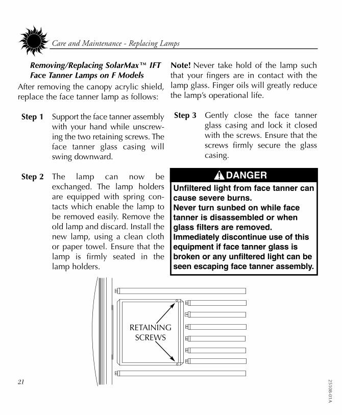
Removing/Replacing SolarMax™ IFTFace Tanner Lamps on F Models
After removing the canopy acrylic shield,replace the face tanner lamp as follows:
Step 1 Support the face tanner assemblywith your hand while unscrew-ing the two retaining screws. Theface tanner glass casing willswing downward.
Step 2 The lamp can now beexchanged. The lamp holdersare equipped with spring con-tacts which enable the lamp tobe removed easily. Remove theold lamp and discard. Install thenew lamp, using a clean clothor paper towel. Ensure that thelamp is firmly seated in thelamp holders.
Note! Never take hold of the lamp suchthat your fingers are in contact with thelamp glass. Finger oils will greatly reducethe lamp’s operational life.
Step 3 Gently close the face tannerglass casing and lock it closedwith the screws. Ensure that thescrews firmly secure the glasscasing.
RETAININGSCREWS
DANGERUnfiltered light from face tanner cancause severe burns.Never turn sunbed on while facetanner is disassembled or whenglass filters are removed. Immediately discontinue use of thisequipment if face tanner glass isbroken or any unfiltered light can beseen escaping face tanner assembly.

2510
8-01
A 22
roubleshooting
Problem SolutionSunbed not tanning
Lamps fail to light and timer dis-play is blank
Timer display changes to indicatea tanning time after the timer but-ton is pressed but lamps do notcome on
Timer display continues to show a0 after the timer button is pressed
One or more lamps fail to light
The face tanners will not come on
The canopy will not stay up
1. Clean sunbed, see Thorough Periodic Cleaning.2. Ensure supply voltage is between 208 and 230V AC.3. Replace lamps if lamp hours are greater than 800hrs.4. Replace acrylic.
1. Make sure the unit is connected to a power source.2. Check source of AC power. Reset circuit breaker or replace fuse.
1. Bypass plug is not installed, see Electrical Connections.2. A non-SunStar® bypass has been used.3. If remote is being used, other than T-Max® Manager, the exter-
nal timer may not be activated.4. Remote wiring is incorrect, see the instructions provided with
the remote interface kit.
1. T-Max® Manager remote system has not yet been set. 2. Sunbed address is not set correctly, see Remote Connections.
1. Check that lamp is installed correctly.2. Switch unlit lamp with a lamp that lights, if new lamp lights
and old lamp still does not, replace old lamp.
1. Face tanners will not relight until cooled.2. Replace face tanner lamp, see Removing/Replacing Face
Tanner Lamp on F Models.
NOTE: Gas springs are manufactured to hold the canopy in itsfully open position as well as allow it to rest fully closed. If leftopen for an extended period of time some creep down mayoccur. This is considered normal. Keep the unit closed whennot in use. If the canopy will not stay fully open when raised...
1. Raise and lower the canopy a few times to lubricate gas springinternal seals.
2. Replace gas springs.
25108-01A
23
Care and Maintenance - Replacing Lamps
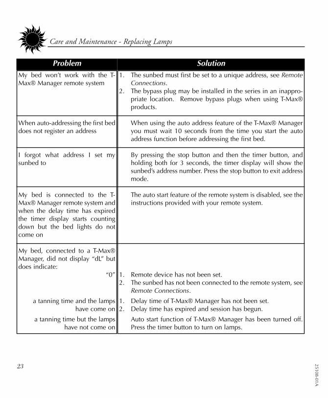
Problem SolutionMy bed won’t work with the T-Max® Manager remote system
When auto-addressing the first beddoes not register an address
I forgot what address I set mysunbed to
My bed is connected to the T-Max® Manager remote system andwhen the delay time has expiredthe timer display starts countingdown but the bed lights do notcome on
My bed, connected to a T-Max®Manager, did not display “dL” butdoes indicate:
“0”
a tanning time and the lampshave come on
a tanning time but the lampshave not come on
1. The sunbed must first be set to a unique address, see RemoteConnections.
2. The bypass plug may be installed in the series in an inappro-priate location. Remove bypass plugs when using T-Max®products.
When using the auto address feature of the T-Max® Manageryou must wait 10 seconds from the time you start the autoaddress function before addressing the first bed.
By pressing the stop button and then the timer button, andholding both for 3 seconds, the timer display will show thesunbed’s address number. Press the stop button to exit addressmode.
The auto start feature of the remote system is disabled, see theinstructions provided with your remote system.
1. Remote device has not been set.2. The sunbed has not been connected to the remote system, see
Remote Connections.
1. Delay time of T-Max® Manager has not been set.2. Delay time has expired and session has begun.
Auto start function of T-Max® Manager has been turned off.Press the timer button to turn on lamps.

2510
8-01
A
M-2
4S

25108-01A
M-2
4SF
2510
8-01
A
M-2
8LE

25108-01A
M-2
8LET
2510
8-01
A
M-2
8LE2
F

25108-01A
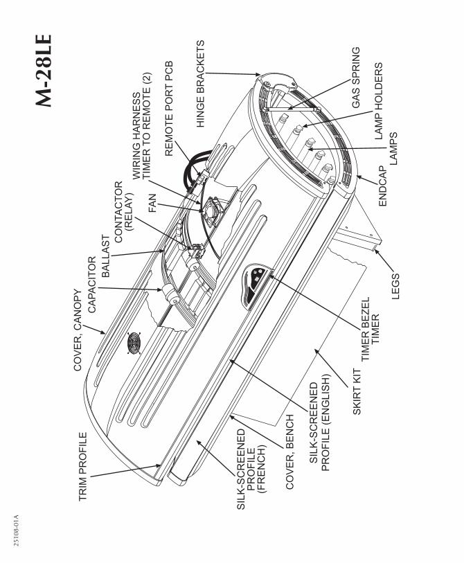
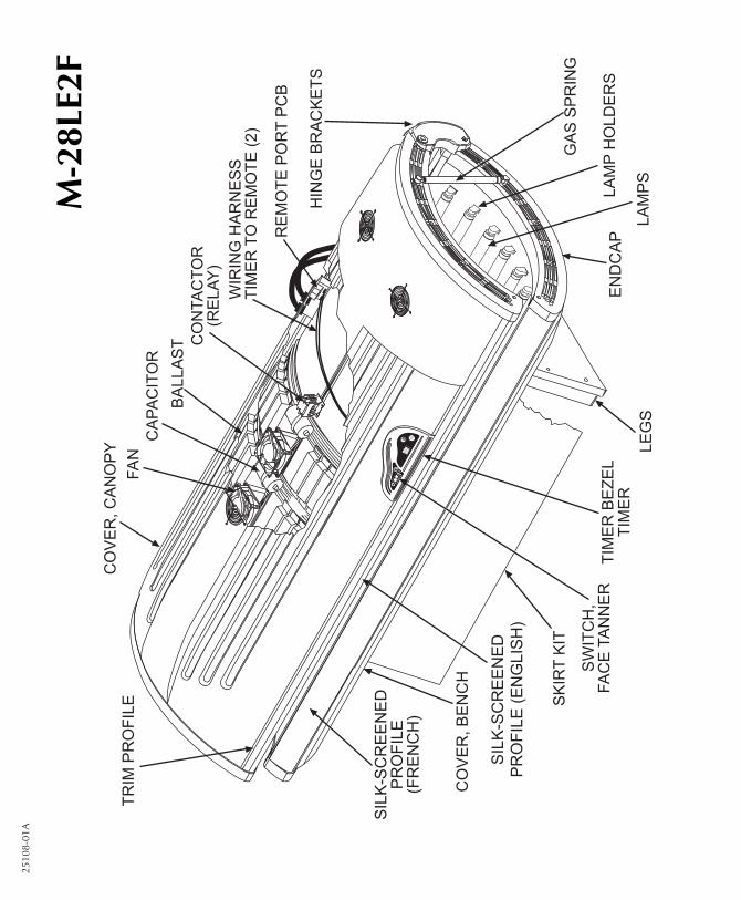
Parts ListThis is a list of parts which may be replaced by theconsumer. Care should be taken when replacinganything related to electrical wiring. We recom-mend contacting a professional electrician.When calling for parts, first state your bed modelas M-24S, M-24SF, M-28LE, M-28LET, or M-28LE2F. Then refer to this list and preceding illus-trations for proper part identification.
Acrylic, Bench*Acrylic, Canopy*Ballast, 30W* (for Turbo lamps)Ballast, 100W (1 for each main lamp, 4 for
each face tanner lamp)Capacitor, 75uFContactor (Relay)Cover, BenchCover, CanopyEndcap Service Kit (1 left and 1 right endcap)FanGas Spring setHardware Kit* (assembly hardware)Hinge Brackets (left and right)Lamp Holder, Turbo*Lamp Holder w/ Starter*Lamp Holder w/o StarterLamp Holder, Face Tanner*LampsLeg Mounts* (found inside the bench)LegsManual*Pillow* Record this information for ease of service:
Date of purchase:
Bench serial number:
Canopy serial number:
Profile* (blank)Remote Control Bypass Plug*Remote Port PCBSchematic Packet*Silk-screened Profile (English)Silk-screened Profile (French)Skirt Kit (front, 2 sides and screws)Starter, S-2* (Turbo)Starter, K-11* (main lamps)Starter, Face Tanner* (ignitor)Starter Holder, Turbo*Switch, Face TannerThermostat, Face Tanner*Timer (complete with timer, buttons, and bezel)Timer BezelTimer Buttons*Trim Profile (plum)Wiring Harness, Timer to Remote
* Not shown

2510
8-01
A
24S 24SFSize
Weight (Pounds) 263 288
Minimum Room Size 6’ x 8’ 6’ x 8’
Electrical -
Voltage (AC) 220 220
Amperage 12 16
Circuit Breaker (Amps) 20 20
Outlet (NEMA standard) 6-20R 6-20R
Main Lamps Velocity® 100W Velocity® 100W/80W
or Golden Tan™ 100W or Golden Tan™ 100W/80W
Ballasts 100W 100W/80W
Face Tanner NA SolarMax™ IFT
FT Ballasts NA 4x100W
Timer System Digital Digital
Max. Exposure Time 20minutes 20minutes
Back-up Timer On-board On-board
Remote Capability T-Max® compatible T-Max® compatible
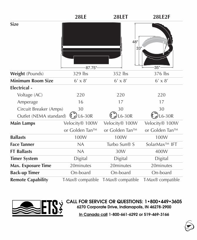
28LE 28LET 28LE2FSize
Weight (Pounds) 329 lbs 352 lbs 376 lbs
Minimum Room Size 6’ x 8’ 6’ x 8’ 6’ x 8’
Electrical -
Voltage (AC) 220 220 220
Amperage 16 17 17
Circuit Breaker (Amps) 30 30 30
Outlet (NEMA standard) L6-30R L6-30R L6-30R
Main Lamps Velocity® 100W Velocity® 100W Velocity® 100W
or Golden Tan™ or Golden Tan™ or Golden Tan™
Ballasts 100W 100W 100W
Face Tanner NA Turbo Sun® S SolarMax™ IFT
FT Ballasts NA 30W 400W
Timer System Digital Digital Digital
Max. Exposure Time 20minutes 20minutes 20minutes
Back-up Timer On-board On-board On-board
Remote Capability T-Max® compatible T-Max® compatible T-Max® compatible
CALL FOR SERVICE OR QUESTIONS: 1•800•449•36056270 Corporate Drive, Indianapolis, IN 46278-2900
In Canada call 1-800-661-6292 or 519-469-3166