Embed Size (px)
Citation preview

Mot
herb
oard
PRL-DL
User Guide
ii
Checklist
Copyright © 2003 ASUSTeK COMPUTER INC. All Rights Reserved.No part of this manual, including the products and software described in it, may bereproduced, transmitted, transcribed, stored in a retrieval system, or translated into anylanguage in any form or by any means, except documentation kept by the purchaser forbackup purposes, without the express written permission of ASUSTeK COMPUTER INC.(“ASUS”).
Product warranty or service will not be extended if: (1) the product is repaired, modified oraltered, unless such repair, modification of alteration is authorized in writing by ASUS; or (2)the serial number of the product is defaced or missing.
ASUS PROVIDES THIS MANUAL “AS IS” WITHOUT WARRANTY OF ANY KIND, EITHEREXPRESS OR IMPLIED, INCLUDING BUT NOT LIMITED TO THE IMPLIED WARRANTIESOR CONDITIONS OF MERCHANTABILITY OR FITNESS FOR A PARTICULAR PURPOSE.IN NO EVENT SHALL ASUS, ITS DIRECTORS, OFFICERS, EMPLOYEES OR AGENTS BELIABLE FOR ANY INDIRECT, SPECIAL, INCIDENTAL, OR CONSEQUENTIAL DAMAGES(INCLUDING DAMAGES FOR LOSS OF PROFITS, LOSS OF BUSINESS, LOSS OF USEOR DATA, INTERRUPTION OF BUSINESS AND THE LIKE), EVEN IF ASUS HAS BEENADVISED OF THE POSSIBILITY OF SUCH DAMAGES ARISING FROM ANY DEFECT ORERROR IN THIS MANUAL OR PRODUCT.
SPECIFICATIONS AND INFORMATION CONTAINED IN THIS MANUAL ARE FURNISHEDFOR INFORMATIONAL USE ONLY, AND ARE SUBJECT TO CHANGE AT ANY TIMEWITHOUT NOTICE, AND SHOULD NOT BE CONSTRUED AS A COMMITMENT BY ASUS.ASUS ASSUMES NO RESPONSIBILITY OR LIABILITY FOR ANY ERRORS ORINACCURACIES THAT MAY APPEAR IN THIS MANUAL, INCLUDING THE PRODUCTSAND SOFTWARE DESCRIBED IN IT.
Products and corporate names appearing in this manual may or may not be registeredtrademarks or copyrights of their respective companies, and are used only for identification orexplanation and to the owners’ benefit, without intent to infringe.
E1172
First EditionJanuary 2003
iii
Fea
ture
s
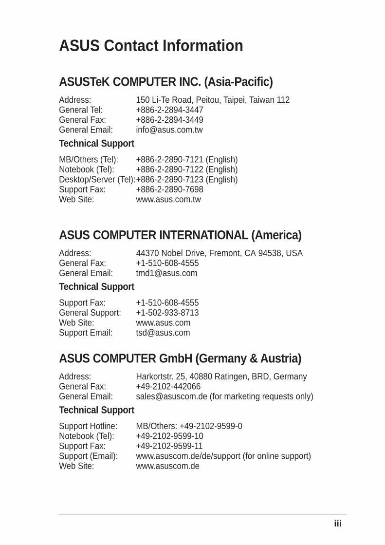
ASUS Contact Information
ASUSTeK COMPUTER INC. (Asia-Pacific)Address: 150 Li-Te Road, Peitou, Taipei, Taiwan 112General Tel: +886-2-2894-3447General Fax: +886-2-2894-3449General Email: [email protected]
Technical Support
MB/Others (Tel): +886-2-2890-7121 (English)Notebook (Tel): +886-2-2890-7122 (English)Desktop/Server (Tel):+886-2-2890-7123 (English)Support Fax: +886-2-2890-7698Web Site: www.asus.com.tw
ASUS COMPUTER INTERNATIONAL (America)Address: 44370 Nobel Drive, Fremont, CA 94538, USAGeneral Fax: +1-510-608-4555General Email: [email protected]
Technical Support
Support Fax: +1-510-608-4555General Support: +1-502-933-8713Web Site: www.asus.comSupport Email: [email protected]
ASUS COMPUTER GmbH (Germany & Austria)Address: Harkortstr. 25, 40880 Ratingen, BRD, GermanyGeneral Fax: +49-2102-442066General Email: [email protected] (for marketing requests only)
Technical Support
Support Hotline: MB/Others: +49-2102-9599-0Notebook (Tel): +49-2102-9599-10Support Fax: +49-2102-9599-11Support (Email): www.asuscom.de/de/support (for online support)Web Site: www.asuscom.de
iv
Safeguards
ContentsNotices ............................................................................................ ii
ASUS contact information .............................................................. iii
FCC/CDC statements ..................................................................... vi
Safety Information ......................................................................... vii
About this guide ............................................................................ viiiHow this guide is organized ................................................ viiiConventions used in this guide ............................................. ixWhere to find more information ............................................. ix
PRL-DL Specifications summary ..................................................... x
Product introduction.................................................. Chapter 11.1 Welcome! ........................................................................... 1-1
1.2 Package contents ............................................................... 1-1
1.3 Special features .................................................................. 1-21.3.1 Product highlights .................................................. 1-21.3.2 Value-added solutions ............................................ 1-4
1.4 Motherboard overview ........................................................ 1-61.4.1 Major components ................................................. 1-61.4.2 Core specifications ................................................ 1-8
Hardware information ................................................ Chapter 22.1 Motherboard installation ..................................................... 2-1
2.1.1 Placement direction ............................................... 2-12.1.2 Screw holes ........................................................... 2-1
2.2 Motherboard layout ............................................................ 2-2
2.3 Before you proceed ............................................................ 2-3
2.4 Central Processing Unit (CPU) ........................................... 2-42.4.1 Overview ................................................................ 2-42.4.2 Installing the CPU .................................................. 2-52.4.3 Installing the CPU heatsink and fan ....................... 2-6
2.5 System memory ................................................................. 2-82.5.1 Overview ................................................................ 2-82.5.2 Memory Configurations .......................................... 2-92.5.3 Installing a DIMM ................................................. 2-102.5.4 Removing a DIMM ............................................... 2-10
2.6 Expansion slots .................................................................2-112.6.1 Installing an expansion card .................................2-11
v
Contents2.6.2 Configuring an expansion card .............................2-112.6.3 PCI slots .............................................................. 2-13
2.7 Switches and jumpers ...................................................... 2-142.7.1 Switches .............................................................. 2-142.7.2 Jumpers ............................................................... 2-16
2.8 Connectors ....................................................................... 2-19
2.9 Onboard LEDs.................................................................. 2-262.9.1 Port 80h post code LEDs ..................................... 2-27
Powering up ............................................................... Chapter 33.1 Starting up for the first time ................................................ 3-1
3.2 Powering off the computer ................................................. 3-2
BIOS setup ................................................................. Chapter 44.1 Managing and updating your BIOS .................................... 4-1
4.1.1 Creating a bootable disk ........................................ 4-14.1.2 Updating the BIOS ................................................. 4-3
4.2 BIOS Setup program .......................................................... 4-54.2.1 BIOS menu bar ...................................................... 4-64.2.2 Legend bar ............................................................. 4-6
4.3 Main Menu.......................................................................... 4-84.3.1 Primary/Secondary/Tertiary Master/Slave ........... 4-104.3.2 Keyboard Features .............................................. 4-14
4.4 Advanced Menu ............................................................... 4-154.4.1 Chip Configuration ............................................... 4-174.4.2 I/O Device Configuration ...................................... 4-184.4.3 PCI Configuration ................................................ 4-20
4.5 Power Menu ..................................................................... 4-224.5.1 Power Up Control ................................................ 4-244.5.2 Hardware Monitor ................................................ 4-26
4.6 Boot Menu ........................................................................ 4-274.6.1 Slot Configuration ................................................ 4-30
4.7 Server Menu ..................................................................... 4-314.7.1 Event Log Viewer ................................................. 4-32
4.8 Exit Menu ......................................................................... 4-33
Support CD ................................................................. Chapter 5
vi
FCC/CDC statements
Federal Communications Commission Statement
This device complies with FCC Rules Part 15. Operation is subject to thefollowing two conditions:
• This device may not cause harmful interference, and
• This device must accept any interference received including interferencethat may cause undesired operation.
This equipment has been tested and found to comply with the limits for aClass B digital device, pursuant to Part 15 of the FCC Rules. These limitsare designed to provide reasonable protection against harmful interferencein a residential installation. This equipment generates, uses and can radiateradio frequency energy and, if not installed and used in accordance withmanufacturer’s instructions, may cause harmful interference to radiocommunications. However, there is no guarantee that interference will notoccur in a particular installation. If this equipment does cause harmfulinterference to radio or television reception, which can be determined byturning the equipment off and on, the user is encouraged to try to correct theinterference by one or more of the following measures:
• Reorient or relocate the receiving antenna.
• Increase the separation between the equipment and receiver.
• Connect the equipment to an outlet on a circuit different from that towhich the receiver is connected.
• Consult the dealer or an experienced radio/TV technician for help.
Canadian Department of Communications Statement
This digital apparatus does not exceed the Class B limits for radio noiseemissions from digital apparatus set out in the Radio InterferenceRegulations of the Canadian Department of Communications.
This class B digital apparatus complies with Canadian ICES-003.
The use of shielded cables for connection of the monitor to thegraphics card is required to assure compliance with FCC regulations.Changes or modifications to this unit not expressly approved by theparty responsible for compliance could void the user’s authority tooperate this equipment.
vii
Safety information
Electrical safety
• To prevent electrical shock hazard, disconnect the power cable fromthe electrical outlet before relocating the system.
• When adding or removing devices to or from the system, ensure thatthe power cables for the devices are unplugged before the signalcables are connected. If possible, disconnect all power cables from theexisting system before you add a device.
• Before connecting or removing signal cables from the motherboard,ensure that all power cables are unplugged.
• Seek professional assistance before using an adpater or extensioncord. These devices could interrupt the grounding circuit.
• Make sure that your power supply is set to the correct voltage in yourarea. If you are not sure about the voltage of the electrical outlet youare using, contact your local power company.
• If the power supply is broken, do not try to fix it by yourself. Contact aqualified service technician or your retailer.
Operation safety• Before installing the product and adding devices on it, carefully read all
the documentation that came with the package.
• Before using the product, make sure all cables are correctly connectedand the power cables are not damaged. If you detect any damage,contact your dealer immediately.
• To avoid short circuits, keep paper clips, screws, and staples away fromconnectors, slots, sockets and circuitry.
• Avoid dust, humidity, and temperature extremes. Do not place theproduct in any area where it may become wet.
• Place the product on a stable surface.
• If you encounter technical problems with the product, contact aqualified service technician or your retailer.
viii
About this guideThis user guide contains the information you need when installing thisASUS motherboard.
How this guide is organizedThis manual contains the following parts:
• Chapter 1: Product introductionThis chapter describes the features of this motherboard. It includesbrief descriptions of the special attributes of the motherboard and thenew technology it supports.
• Chapter 2: Hardware informationThis chapter lists the hardware setup procedures that you have toperform when installing system components. It includes description ofthe switches, jumpers, and connectors on the motherboard.
• Chapter 3: Powering upThis chapter describes the power up sequence and gives informationon the BIOS beep codes.
• Chapter 4: BIOS setupThis chapter tells how to change system settings through the BIOSSetup menus. Detailed descriptions of the BIOS parameters are alsoprovided.
• Chapter 5: OS InstallationThis chapter tells how to install SCSI, LAN, and VGA drivers forvarious operating systems.
ix
Conventions used in this guideTo make sure that you perform certain tasks properly, take note of thefollowing symbols used throughout this manual.
Where to find more informationRefer to the following sources for additional information and for productand software updates.
1. ASUS WebsitesThe ASUS websites worldwide provide updated information on ASUShardware and software products. The ASUS websites are listed in theASUS Contact Information on page x.
2. Optional DocumentationYour product package may include optional documentation, such aswarranty flyers, that may have been added by your dealer. Thesedocuments are not part of the standard package.
WARNING: Information to prevent injury to yourself when tryingto complete a task.
CAUTION: Information to prevent damage to the componentswhen trying to complete a task.
IMPORTANT: Information that you MUST follow to complete atask.
NOTE: Tips and additional information to aid in completing a task.
x
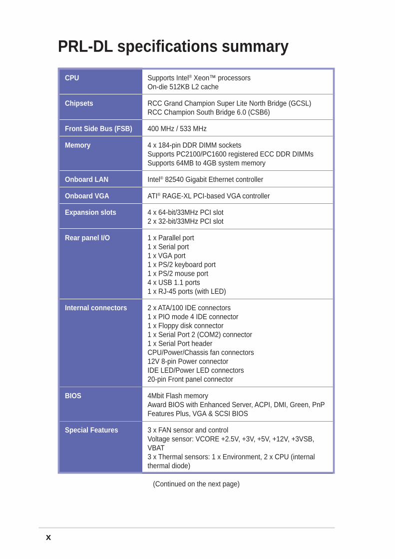
PRL-DL specifications summary
CPU
Chipsets
Front Side Bus (FSB)
Memory
Onboard LAN
Onboard VGA
Expansion slots
Rear panel I/O
Internal connectors
BIOS
Special Features
Supports Intel® Xeon™ processorsOn-die 512KB L2 cache
RCC Grand Champion Super Lite North Bridge (GCSL)RCC Champion South Bridge 6.0 (CSB6)
400 MHz / 533 MHz
4 x 184-pin DDR DIMM socketsSupports PC2100/PC1600 registered ECC DDR DIMMsSupports 64MB to 4GB system memory
Intel® 82540 Gigabit Ethernet controller
ATI® RAGE-XL PCI-based VGA controller
4 x 64-bit/33MHz PCI slot2 x 32-bit/33MHz PCI slot
1 x Parallel port1 x Serial port1 x VGA port1 x PS/2 keyboard port1 x PS/2 mouse port4 x USB 1.1 ports1 x RJ-45 ports (with LED)
2 x ATA/100 IDE connectors1 x PIO mode 4 IDE connector1 x Floppy disk connector1 x Serial Port 2 (COM2) connector1 x Serial Port headerCPU/Power/Chassis fan connectors12V 8-pin Power connectorIDE LED/Power LED connectors20-pin Front panel connector
4Mbit Flash memoryAward BIOS with Enhanced Server, ACPI, DMI, Green, PnPFeatures Plus, VGA & SCSI BIOS
3 x FAN sensor and controlVoltage sensor: VCORE +2.5V, +3V, +5V, +12V, +3VSB,VBAT3 x Thermal sensors: 1 x Environment, 2 x CPU (internalthermal diode)
(Continued on the next page)
xi
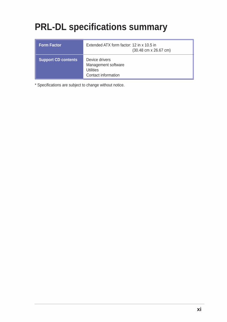
PRL-DL specifications summary
Extended ATX form factor: 12 in x 10.5 in (30.48 cm x 26.67 cm)
Device driversManagement softwareUtilitiesContact information
Form Factor
Support CD contents
* Specifications are subject to change without notice.

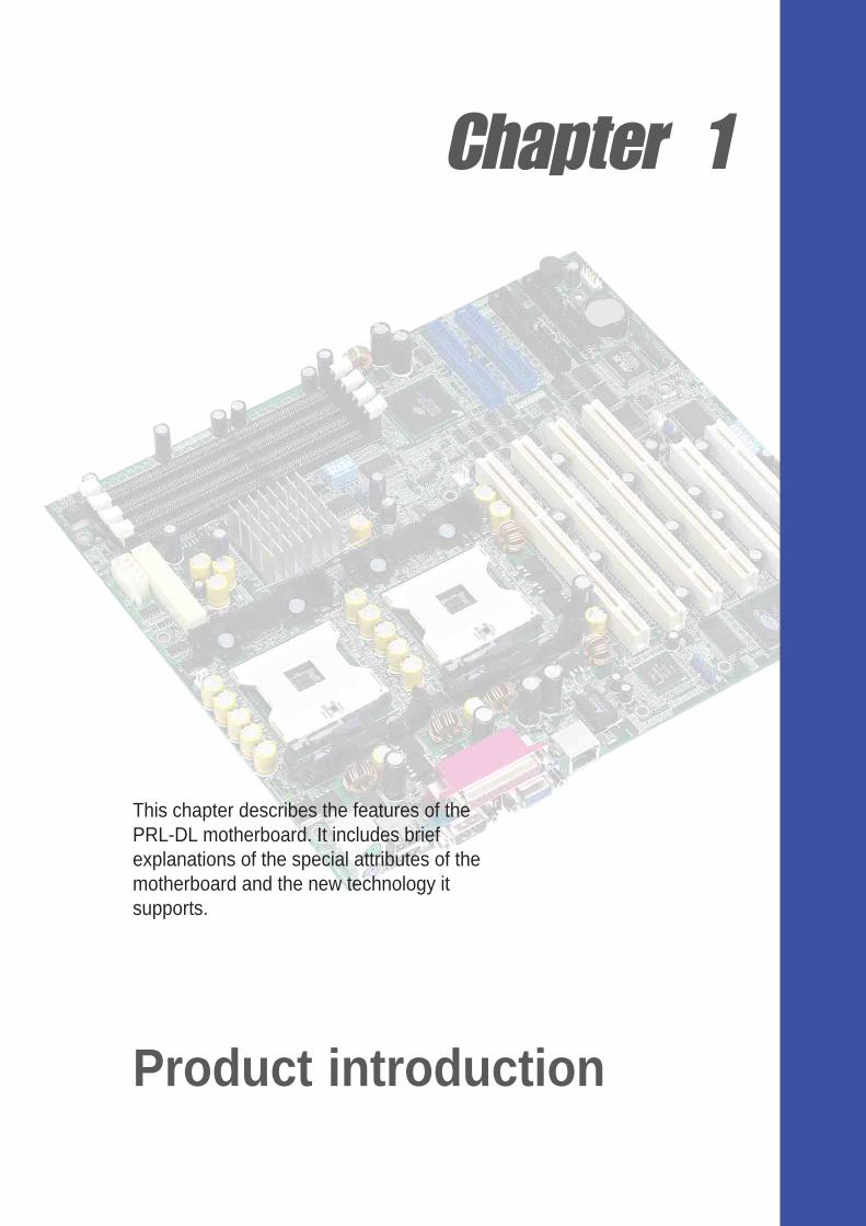
Chapter 1
This chapter describes the features of thePRL-DL motherboard. It includes briefexplanations of the special attributes of themotherboard and the new technology itsupports.
Product introduction
ASUS PRL-DL motherboard
Chapter summary
1.1 Welcome! ........................................................ 1-1
1.2 Package contents .......................................... 1-1
1.3 Special features ............................................. 1-2
1.4 Motherboard overview................................... 1-6
ASUS PRL-DL motherboard user guide 1-1
1.1 Welcome!Thank you for buying the ASUS® PRL-DL motherboard!
The ASUS PRL-DL motherboard delivers a host of new features and latesttechnologies making it another standout in the long line of ASUS qualityserver motherboards!
The PRL-DL incorporates dual Intel® Xeon™ processor in a 603/604-pinpackage coupled with the ServerWorks® Grand Champion Super-Lite(GCSL) System Set to deliver a reliable and high performance dual-processor server platform.
Before you start installing the motherboard, and hardware devices on it,check the items in your package with the list below.
1.2 Package contentsCheck your PRL-DL package for the following items.
If any of the above items is damaged or missing, contact your retailer.
ASUS PRL-DL motherboardExtended ATX form factor: 12 in x 10.5 in (30.48 cm x 26.67 cm)
ASUS PRL-DL support CD
I/O shield
80-conductor ribbon cable for UltraDMA100/66//33 IDE drives
Ribbon cable for a 3.5-inch floppy drive
Bag of extra jumper caps
PRL-DL User Guide
2 x Intel Box CPU mounting plates
1-2 Chapter 1: Product introduction
1.3 Special features
1.3.1 Product highlights
Latest processor technology
The PRL-DL motherboard supports both Intel® Xeon™ processors via dual604-pin surface mount ZIF sockets. The processor features the Intel®
NetBurst™ micro-architecture that includes hyper-pipelined technology, arapid execution engine, a 533MHz or a 400MHz system bus, and anexecution trace cache to offer a significant increase in performance. Seepage 2-4 for more information.
DDR memory support
Employing the Double Data Rate (DDR) memory technology, the PRL-DLmotherboard supports up to 4GB of system memory using PC2100/1600registered ECC DDR DIMMs. The ultra-fast 266MHz memory bus doublesthe speed of the PC100 SDRAM to deliver the required bandwidth for thelatest 3D graphics, multimedia, and Internet applications. See page 2-10.
Advanced 64-bit PCI slots
The 64-bit/33MHz PCI slots maximize I/O bandwidth for current 64-bit PCIcards that support 33MHz bus.
ATA/100 IDE support
The dual-channel bus master IDE connectors comply with the ATA/100protocol and supports ATA/100, Multi-Word DMA Mode2, PIO modes 3 & 4IDE devices such as ATAPI IDE CD-ROM, CD-R/RW, ZIP, and LS-120drives.
Third IDE Channel support
The CSB6 South Bridge chip provides a third IDE with PIO mode 3/4support which provides more device connectivity in this server system.
ASUS PRL-DL motherboard user guide 1-3
Onboard LAN
The motherboard comes with the Intel® 82540 Gigabit Ethernet controllerto support the latest LAN technologies.
Onboard VGA
The ATI Rage-XL PCI-based VGA controller integrates an 8MB displaySDRAM to provide onboard video solution.
1-4 Chapter 1: Product introduction
1.3.2 Value-added solutions
Temperature, fan, and voltage monitoring
The CPU temperature is monitored by the ASUS ASIC to preventoverheating and damage. The system fan rotations per minute (RPM) ismonitored for timely failure detection. The system voltage levels aremonitored to ensure stable supply of current for critical components.
Dual function power switch
While the system is ON, pressing the power switch for less than 4 secondsputs the system to sleep mode or to soft-off mode, depending on the BIOSsetting. Pressing the power switch for more than 4 seconds lets thesystem enter the soft-off mode regardless of the BIOS setting.
Remote Ring In
This feature allows the system to wake up remotely through an internal orexternal modem, if present.
Wake-Up support
The motherboard includes Wake-On-LAN, Wake-On-Ring, and BIOSWake-Up features.
Server management
The motherboard comes with an ASMC connector that supports theoptional ASMC-HE/ME/LE card to comply with server reliability, availability,and serviceability requirements. Remote management response viaremote diagnostics and troubleshooting still works even when theoperating system has stopped functioning.
ACPI ready
The Advanced Configuration power Interface (ACPI) provides more energysaving features for operating systems that support OS Direct PowerManagement (OSPM).
Concurrent PCI
This feature allows multiple PCI transfers from PCI master buses to thememory and processor.
ASUS PRL-DL motherboard user guide 1-5
Chassis intrusion detection
The motherboard supports chassis intrusion monitoring through the ASUSASIC. A chassis intrusion event is retained in the system memory for moreprotection.
Smart BIOS
The 4Mbit firmware gives an easy-to-use interface that provides morecontrol and protection to the motherboard. The BIOS has a boot blockwrite protection and HD/SCSI/MO/ZIP/CD/Floppy boot selection, and isYear 2000 certified.
Compliance
Both the BIOS and the hardware levels of the motherboard meet thestringent requirements for SDG 2.0 certification. The new SDG 2.0requirements for systems and components are based on the followinghigh-level goals: support for Plug-and-Play compatibility and powermanagement for configuring and managing all system components, 32-bitdevice drivers, and installation procedures for Windows NT/2000/XP.Color-coded connectors and descriptive icons make identification easy asrequired by the PC ‘99 specification.
1-6 Chapter 1: Product introduction
1.4 Motherboard overviewBefore you install the PRL-DL motherboard, familiarize yourself with itsphysical configuration and available features to facilitate the motherboardinstallation and future upgrades. A sufficient knowledge of the motherboardspecifications will also help you avoid mistakes that may damage theboard and its components.
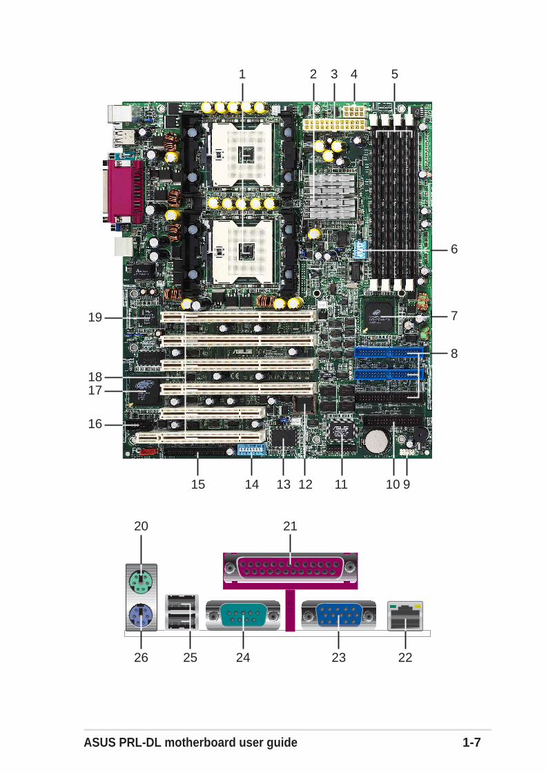
1.4.1 Major componentsThe following are the major components of the PRL-DL motherboard aspointed out in the picture on page 1-7.
1. 604-pin CPU sockets
2. ServerWorks® Grand ChampionSuperLite (GCSL) North Bridge
3. 24/20-pin ATX power connector
4. 8-pin 12V SSI power connector
5. DDR DIMM sockets
6. DIP switches
7. Serverworks CSB6 South Bridge
8. IDE connectors
9. USB header
10. Floppy connector
11. ASUS ASIC
12. Flash ROM
13. LPC Super-I/O controller
14. DIP switches
15. 80-pin ASMB daughterboardconnector
16. Serial port 2
17. ATI Rage-XL VGA controller
18. 64-bit PCI slots (PCI64-1 toPCI64-4), 32-bit PCI slots(PCI-1 & PCI-2)
19. Intel® 82540 Gigabit Ethernetcontroller
20. PS/2 mouse port
21. Parallel port
22. RJ-45 ports
23. VGA port
24. Serial port 1
25. USB ports 1 and 2
26. Keyboard port
See page 1-8 for the specifications of each component. Refer toChapter 2 for detailed information on the components.
ASUS PRL-DL motherboard user guide 1-7
1 5
13
16
8
2
719
3
1011
17
4
6
1214
18
15 9
20 21
26 25 24 23 22
1-8 Chapter 1: Product introduction
604-pin CPU sockets. A 604-pin surface mount, Zero InsertionForce (ZIF) socket for the Intel® Xeon™ processor with 512KB L2cache and a 533MHz or a 400MHz system bus that allows up to4.26GB/s or 3.2GB/s data transfer rate.
ServerWorks® Grand Champion SuperLite north bridge . CMIC-SL. The Champion Memory and I/O Controller SuperLite (CMIC-SL) acts as the host bridge of the Grand Champion SuperLite(GCSL) SystemSet. The GCSL device interfaces directly to theprocessor bus, and integrates the functions of the main memorycontroller and the Inter Module Bus (IMB) interface unit. Theprocessor interface supports a 400/533 MHz Front Side Bus (FSB)providing a 3.2GB/s or 4.26GB/s bandwidth, memory bandwidthwith up to 4GB registered ECC PC1600/2100 DDR DIMMs, andtwo high speed IMBs plus one thin IMB to connect to the southbridge CSB6.
24/20-pin ATX power connector. This power connector is for anATX power supply.
8-pin 12V SSI power connector. This power connector is for anATX power supply.
DDR DIMM sockets. These four 184-pin DIMM sockets support upto 4GB system memory using registered ECC PC1600/2100 DDRDIMMs.
DIP switches. This 5-switch Dual Inline Package (DIP) allows youto set the CPU external frequency.
ServerWorks® South Bridge, CSB6 performs as a PCI to LPC(Low Pin Count) Bridge and integrates PCI master/slave functions,DMA controller, ATA100 IDE interface, USB contoller, SMBus host,ACPI and other integral functions.
IDE connectors. These dual-channel bus master IDE connectorssupport up to four Ultra DMA/100/66, PIO Modes 3 & 4 IDEdevices. Both the primary (blue) and secondary (blue) connectorsare slotted to prevent incorrect insertion of the IDE ribbon cable.
Front USB header. A Front USB header is available for additionalUSB port connectors.
9
8
7
6
5
4
3
2
1
1.4.2 Core specifications
ASUS PRL-DL motherboard user guide 1-9
Floppy disk connector. This connector accommodates theprovided ribbon cable for the floppy disk drive. One side of theconnector is slotted to prevent incorrect insertion of the floppy diskcable.
ASUS ASIC. This chip performs multiple system functions thatinclude hardware and system voltage monitoring, IRQ routing,among others.
Flash ROM. This 4Mb firmware contains the programmable BIOSprogram.
LPC super I/O controller. This Low Pin Count (LPC) interfaceprovides the commonly used Super I/O functionality. The chipsetsupports UART compatible serial ports, one parallel port with EPPand ECP capabilities, a floppy drive, and PS/2 keyboard andmouse.
DIP switches. This Dual Inline Package (DIP) switch allows you toset the frequencies.
50-pin ASMB Connector. This connector supports the ASMBproprietary Server Management daughter card.
Serial port 2. This 9-pin COM2 port is for pointing devices or otherserial devices.
ATI Rage-XL VGA controller. This PCI-based VGA controllersupports up to 8MB display SDRAM for 1280x1024 and true colorresolutions.
64-bit PCI/32-bit PCI slots. Four 64-bit/33MHz PCI slots and two32-bit/33MHz PCI expansion slots support bus master PCI cards.
Intel® 82540 32bit PCI Gigabit Ethernet Controller. This LANcontroller fully supports 10BASE-T/100BASE-TX/1000BASE-Tnetworking protocols and data rates up to 1000Mbps, 100Mbps,and 10Mbps.
PS/2 mouse port. This green 6-pin connector is for a PS/2 mouse.
Parallel port. This 25-pin port connects a parallel printer, ascanner, or other devices.
RJ-45 ports. These ports allows connection to a Local AreaNetwork (LAN) through a network hub.
11
12
13
14
15
16
17
18
19
10
20
21
22
1-10 Chapter 1: Product introduction
VGA port. This port is for a VGA-monitor or other VGA-compatibledevices.
Serial port 1. This 9-pin COM1 port is for pointing devices or otherserial devices.
USB 1.1 ports. These two 4-pin Universal Serial Bus (USB) portsare available for connecting USB devices.
PS/2 keyboard port. This purple 6-pin connector is for a PS/2keyboard.
24
25
23
26
Chapter 2
Hardware information
This chapter describes the hardware setupprocedures that you have to perform wheninstalling system components. It includesdetails on the switches, jumpers, andconnectors on the motherboard.
ASUS PRL-DL motherboard
Chapter summary
2.1 Motherboard installation ............................... 2-1
2.2 Motherboard layout ....................................... 2-2
2.3 Before you proceed ....................................... 2-3
2.4 Central Processing Unit (CPU) ..................... 2-4
2.5 System memory ............................................. 2-8
2.6 Expansion slots ............................................2-11
2.7 Switches and jumpers ................................. 2-14
2.8 Connectors ................................................... 2-19
ASUS PRL-DL motherboard user guide 2-1
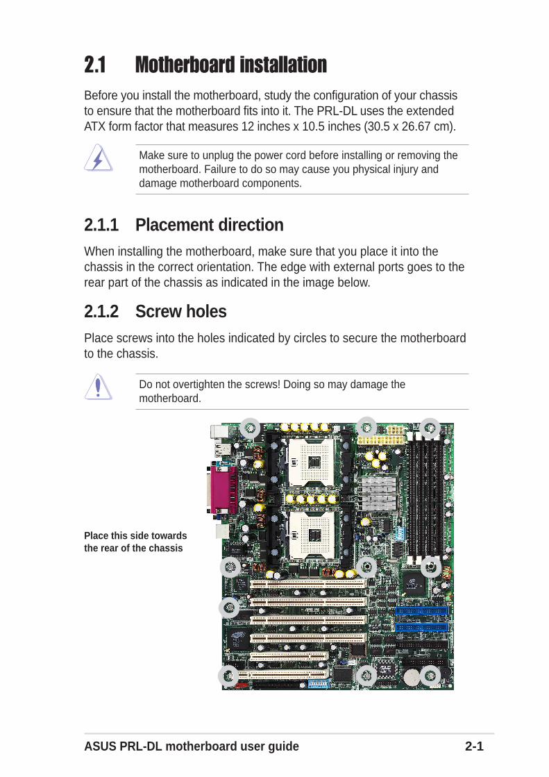
2.1 Motherboard installationBefore you install the motherboard, study the configuration of your chassisto ensure that the motherboard fits into it. The PRL-DL uses the extendedATX form factor that measures 12 inches x 10.5 inches (30.5 x 26.67 cm).
Do not overtighten the screws! Doing so may damage themotherboard.
2.1.1 Placement directionWhen installing the motherboard, make sure that you place it into thechassis in the correct orientation. The edge with external ports goes to therear part of the chassis as indicated in the image below.
2.1.2 Screw holesPlace screws into the holes indicated by circles to secure the motherboardto the chassis.
Make sure to unplug the power cord before installing or removing themotherboard. Failure to do so may cause you physical injury anddamage motherboard components.
Place this side towardsthe rear of the chassis
2-2 Chapter 2: Hardware information
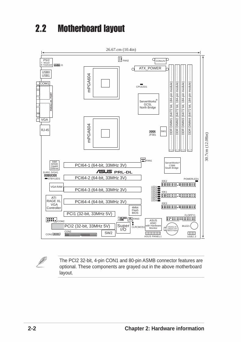
2.2 Motherboard layout
The PCI2 32-bit, 4-pin CON1 and 80-pin ASMB connector features areoptional. These components are grayed out in the above motherboardlayout.
IDE2
FLOPPY1
ASUSASIC
with HardwareMonitor
4MbitFlashBIOS
PRL-DL
PCI64-1 (64-bit, 33MHz 3V)
FAN3
ASUS PANEL1
ATIRAGE XL
VGAController
JVGA1
BUZZ1
CON1
PCI2 (32-bit, 33MHz 5V)
ServerWorks CSB6
South Bridge
®
30.7
cm (
12.0
8in)
®
COM2
SuperI/O
J3
CR2032 3VLithium Cell
CMOS Power
mP
GA
604
mP
GA
604
DD
R D
IMM
1 (6
4/72
bit,
184
-pin
mod
ule)
0 1
DD
R D
IMM
2 (6
4/72
bit,
184
-pin
mod
ule)
2 3
DD
R D
IMM
3 (6
4/72
bit,
184
-pin
mod
ule)
4 5
DD
R D
IMM
4 (6
4/72
bit,
184
-pin
mod
ule)
6 7
CON2
J1
SW2
FAN1
FAN2
JLAN1
JFSB1
VGA RAM
CLRCMOS1
Intel82540GigabitEthernet
ATX_POWER
CON12V
SW1
POWERLED1
LED8
STBYLED1
CPULED1
LED7LED6LED5LED4LED3LED2LED1
USB0USB1
COM1
PAR
AL
LE
L P
OR
T
VGA
RJ-45
PS/2T: MouseB: Keyboard
26.67.cm (10.4in)
PCI1 (32-bit, 33MHz 5V)
IDE1
IDE3
ServerWorksGCSL
North Bridge
®
J1
PCI64-2 (64-bit, 33MHz 3V)
PCI64-3 (64-bit, 33MHz 3V)
PCI64-4 (64-bit, 33MHz 3V)
USB2.3
ASUS PRL-DL motherboard user guide 2-3
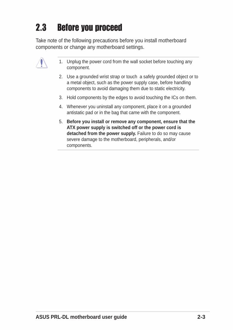
2.3 Before you proceedTake note of the following precautions before you install motherboardcomponents or change any motherboard settings.
1. Unplug the power cord from the wall socket before touching anycomponent.
2. Use a grounded wrist strap or touch a safely grounded object or toa metal object, such as the power supply case, before handlingcomponents to avoid damaging them due to static electricity.
3. Hold components by the edges to avoid touching the ICs on them.
4. Whenever you uninstall any component, place it on a groundedantistatic pad or in the bag that came with the component.
5. Before you install or remove any component, ensure that theATX power supply is switched off or the power cord isdetached from the power supply. Failure to do so may causesevere damage to the motherboard, peripherals, and/orcomponents.
2-4 Chapter 2: Hardware information
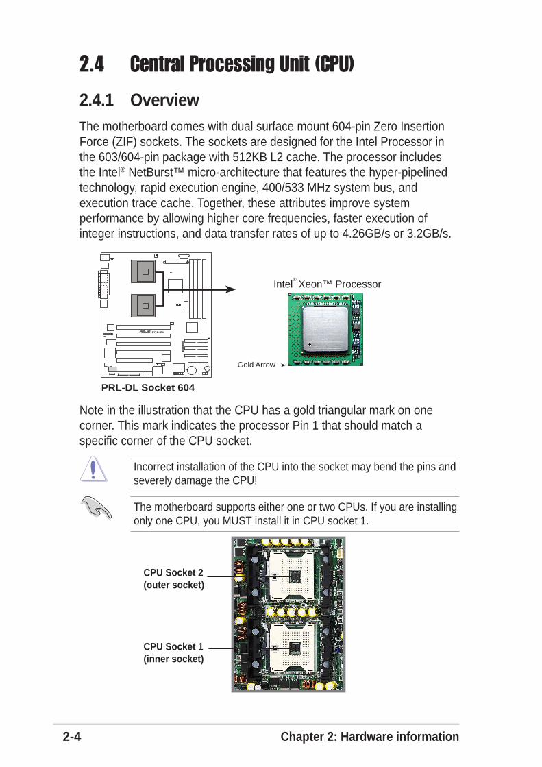
2.4 Central Processing Unit (CPU)
2.4.1 OverviewThe motherboard comes with dual surface mount 604-pin Zero InsertionForce (ZIF) sockets. The sockets are designed for the Intel Processor inthe 603/604-pin package with 512KB L2 cache. The processor includesthe Intel® NetBurst™ micro-architecture that features the hyper-pipelinedtechnology, rapid execution engine, 400/533 MHz system bus, andexecution trace cache. Together, these attributes improve systemperformance by allowing higher core frequencies, faster execution ofinteger instructions, and data transfer rates of up to 4.26GB/s or 3.2GB/s.
Note in the illustration that the CPU has a gold triangular mark on onecorner. This mark indicates the processor Pin 1 that should match aspecific corner of the CPU socket.
Incorrect installation of the CPU into the socket may bend the pins andseverely damage the CPU!
PRL-DL®
PRL-DL Socket 604
Gold Arrow
Intel Xeon™ Processor®
The motherboard supports either one or two CPUs. If you are installingonly one CPU, you MUST install it in CPU socket 1.
CPU Socket 2(outer socket)
CPU Socket 1(inner socket)
ASUS PRL-DL motherboard user guide 2-5
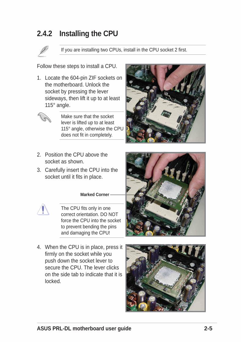
Follow these steps to install a CPU.
1. Locate the 604-pin ZIF sockets onthe motherboard. Unlock thesocket by pressing the leversideways, then lift it up to at least115° angle.
2. Position the CPU above thesocket as shown.
3. Carefully insert the CPU into thesocket until it fits in place.
Make sure that the socketlever is lifted up to at least115° angle, otherwise the CPUdoes not fit in completely.
The CPU fits only in onecorrect orientation. DO NOTforce the CPU into the socketto prevent bending the pinsand damaging the CPU!
4. When the CPU is in place, press itfirmly on the socket while youpush down the socket lever tosecure the CPU. The lever clickson the side tab to indicate that it islocked.
If you are installing two CPUs, install in the CPU socket 2 first.
2.4.2 Installing the CPU
Marked Corner
2-6 Chapter 2: Hardware information
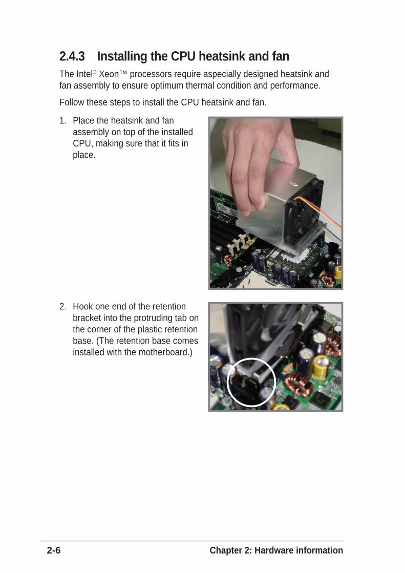
The Intel® Xeon™ processors require aspecially designed heatsink andfan assembly to ensure optimum thermal condition and performance.
Follow these steps to install the CPU heatsink and fan.
2.4.3 Installing the CPU heatsink and fan
1. Place the heatsink and fanassembly on top of the installedCPU, making sure that it fits inplace.
2. Hook one end of the retentionbracket into the protruding tab onthe corner of the plastic retentionbase. (The retention base comesinstalled with the motherboard.)
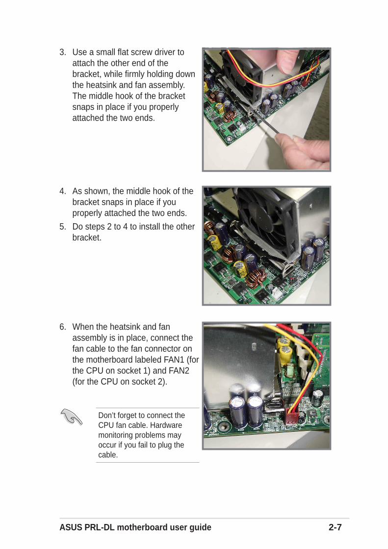
ASUS PRL-DL motherboard user guide 2-7
3. Use a small flat screw driver toattach the other end of thebracket, while firmly holding downthe heatsink and fan assembly.The middle hook of the bracketsnaps in place if you properlyattached the two ends.
4. As shown, the middle hook of thebracket snaps in place if youproperly attached the two ends.
5. Do steps 2 to 4 to install the otherbracket.
6. When the heatsink and fanassembly is in place, connect thefan cable to the fan connector onthe motherboard labeled FAN1 (forthe CPU on socket 1) and FAN2(for the CPU on socket 2).
Don’t forget to connect theCPU fan cable. Hardwaremonitoring problems mayoccur if you fail to plug thecable.
2-8 Chapter 2: Hardware information
2.5 System memory
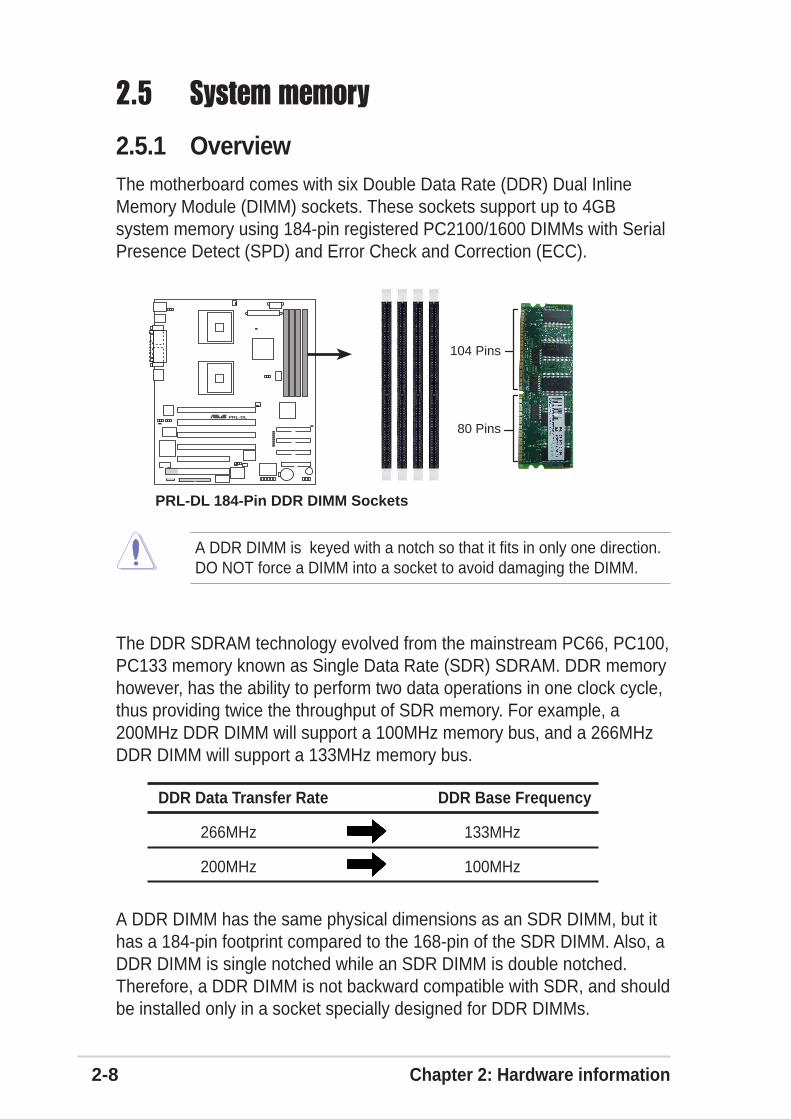
2.5.1 OverviewThe motherboard comes with six Double Data Rate (DDR) Dual InlineMemory Module (DIMM) sockets. These sockets support up to 4GBsystem memory using 184-pin registered PC2100/1600 DIMMs with SerialPresence Detect (SPD) and Error Check and Correction (ECC).
A DDR DIMM is keyed with a notch so that it fits in only one direction.DO NOT force a DIMM into a socket to avoid damaging the DIMM.
The DDR SDRAM technology evolved from the mainstream PC66, PC100,PC133 memory known as Single Data Rate (SDR) SDRAM. DDR memoryhowever, has the ability to perform two data operations in one clock cycle,thus providing twice the throughput of SDR memory. For example, a200MHz DDR DIMM will support a 100MHz memory bus, and a 266MHzDDR DIMM will support a 133MHz memory bus.
A DDR DIMM has the same physical dimensions as an SDR DIMM, but ithas a 184-pin footprint compared to the 168-pin of the SDR DIMM. Also, aDDR DIMM is single notched while an SDR DIMM is double notched.Therefore, a DDR DIMM is not backward compatible with SDR, and shouldbe installed only in a socket specially designed for DDR DIMMs.
DDR Data Transfer Rate DDR Base Frequency
266MHz 133MHz
200MHz 100MHz
PRL-DL®
PRL-DL 184-Pin DDR DIMM Sockets
80 Pins
104 Pins
ASUS PRL-DL motherboard user guide 2-9
The system chipset only supports PC1600/2100 registered ECCDIMMs. Make sure to use only the specified DIMM types for stablesystem operation.
2.5.2 Memory ConfigurationsThe motherboard supports system memory of up to 4GB in a one-waynon-interleaved configuration.
Memory configuration tableDIMM Socket 184-pin ECC DDR DIMM Total Memory
DDRA1 SDRAM 128MB, 256MB, 512MB, 1GB, 2GB (x1) =
DDRA2 SDRAM 128MB, 256MB, 512MB, 1GB, 2GB (x1) =
DDRB1 SDRAM 128MB, 256MB, 512MB, 1GB, 2GB (x1) =
DDRB2 SDRAM 128MB, 256MB, 512MB, 1GB, 2GB (x1) =
Total System Memory (Max. 4GB) =
2-10 Chapter 2: Hardware information
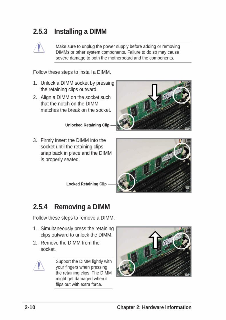
2.5.3 Installing a DIMM
Make sure to unplug the power supply before adding or removingDIMMs or other system components. Failure to do so may causesevere damage to both the motherboard and the components.
Follow these steps to install a DIMM.
1. Unlock a DIMM socket by pressingthe retaining clips outward.
2. Align a DIMM on the socket suchthat the notch on the DIMMmatches the break on the socket.
3. Firmly insert the DIMM into thesocket until the retaining clipssnap back in place and the DIMMis properly seated.
1. Simultaneously press the retainingclips outward to unlock the DIMM.
2. Remove the DIMM from thesocket.
Support the DIMM lightly withyour fingers when pressingthe retaining clips. The DIMMmight get damaged when itflips out with extra force.
Unlocked Retaining Clip
Locked Retaining Clip
2.5.4 Removing a DIMMFollow these steps to remove a DIMM.
ASUS PRL-DL motherboard user guide 2-11
2.6 Expansion slotsIn the future, you may need to install expansion cards. The following sub-sections describe the slots and the expansion cards that they support.
2.6.1 Installing an expansion cardFollow these steps to install an expansion card.
1. Before installing the expansion card, read the documentation thatcame with it and make the necessary hardware settings for the card.
2. Remove the system unit cover (if your motherboard is already installedin a chassis).
3. Remove the bracket opposite the slot that you intend to use. Keep thescrew for later use.
4. Align the card connector with the slot and press firmly until the card iscompletely seated on the slot.
5. Secure the card to the chassis with the screw you removed earlier.
6. Replace the system cover.
Make sure to unplug the power cord before adding or removingexpansion cards. Failure to do so may cause you physical injury anddamage motherboard components.
2.6.2 Configuring an expansion cardAfter installing the expansion card, configure the it by adjusting thesoftware settings.
1. Turn on the system and change the necessary BIOS settings, if any.See Chapter 4 for information on BIOS setup.
2. Assign an IRQ to the card. Refer to the tables on the next page.
3. Install the software drivers for the expansion card.
2-12 Chapter 2: Hardware information
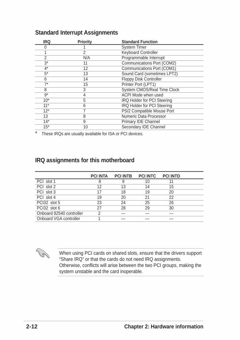
Standard Interrupt AssignmentsIRQ Priority Standard Function 0 1 System Timer 1 2 Keyboard Controller 2 N/A Programmable Interrupt 3* 11 Communications Port (COM2) 4* 12 Communications Port (COM1) 5* 13 Sound Card (sometimes LPT2) 6 14 Floppy Disk Controller 7* 15 Printer Port (LPT1) 8 3 System CMOS/Real Time Clock 9* 4 ACPI Mode when used10* 5 IRQ Holder for PCI Steering11* 6 IRQ Holder for PCI Steering12* 7 PS/2 Compatible Mouse Port13 8 Numeric Data Processor14* 9 Primary IDE Channel15* 10 Secondary IDE Channel
* These IRQs are usually available for ISA or PCI devices.
When using PCI cards on shared slots, ensure that the drivers support“Share IRQ” or that the cards do not need IRQ assignments.Otherwise, conflicts will arise between the two PCI groups, making thesystem unstable and the card inoperable.
IRQ assignments for this motherboard
PCI INTA PCI INTB PCI INTC PCI INTDPCI slot 1 8 9 10 11PCI slot 2 12 13 14 15PCI slot 3 17 18 19 20PCI slot 4 19 20 21 22PCI32 slot 5 23 24 25 26PCI32 slot 6 27 28 29 30Onboard 82540 controller 2 — — —Onboard VGA controller 1 — — —
ASUS PRL-DL motherboard user guide 2-13
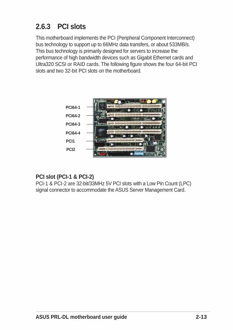
2.6.3 PCI slotsThis motherboard implements the PCI (Peripheral Component Interconnect)bus technology to support up to 66MHz data transfers, or about 533MB/s.This bus technology is primarily designed for servers to increase theperformance of high bandwidth devices such as Gigabit Ethernet cards andUltra320 SCSI or RAID cards. The following figure shows the four 64-bit PCIslots and two 32-bit PCI slots on the motherboard.
PCI slot (PCI-1 & PCI-2)PCI-1 & PCI-2 are 32-bit/33MHz 5V PCI slots with a Low Pin Count (LPC)signal connector to accommodate the ASUS Server Management Card.
PCI64-1
PCI64-2
PCI64-3
PCI64-4
PCI1
PCI2
2-14 Chapter 2: Hardware information
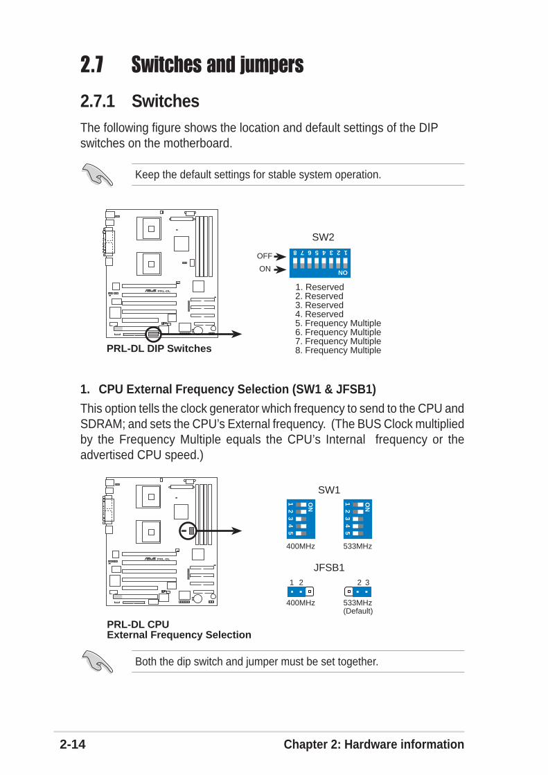
2.7 Switches and jumpers
2.7.1 SwitchesThe following figure shows the location and default settings of the DIPswitches on the motherboard.
PRL-DL®
PRL-DL DIP Switches
SW2
1. Reserved2. Reserved3. Reserved4. Reserved 5. Frequency Multiple6. Frequency Multiple7. Frequency Multiple8. Frequency Multiple
ON
12345678
OFF
ON
Keep the default settings for stable system operation.
1. CPU External Frequency Selection (SW1 & JFSB1)
This option tells the clock generator which frequency to send to the CPU andSDRAM; and sets the CPU’s External frequency. (The BUS Clock multipliedby the Frequency Multiple equals the CPU’s Internal frequency or theadvertised CPU speed.)
Both the dip switch and jumper must be set together.
PRL-DL®
PRL-DL CPUExternal Frequency Selection
(Default)533MHz400MHz
SW1
JFSB1
533MHz400MHz
1 2 32
ON
12
34
5
ON
12
34
5
ASUS PRL-DL motherboard user guide 2-15
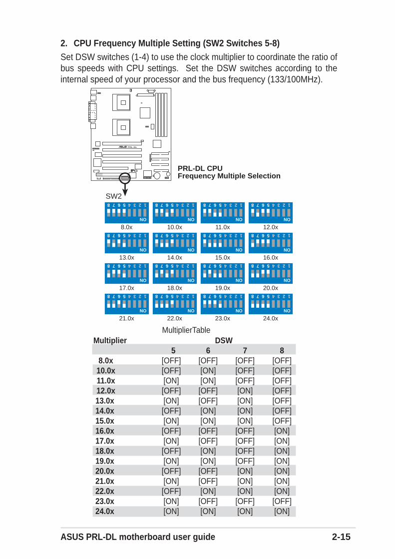
2. CPU Frequency Multiple Setting (SW2 Switches 5-8)Set DSW switches (1-4) to use the clock multiplier to coordinate the ratio ofbus speeds with CPU settings. Set the DSW switches according to theinternal speed of your processor and the bus frequency (133/100MHz).
PRL-DL®
PRL-DL CPUFrequency Multiple Selection
ON
12345678
12.0x
ON
12345678
11.0x
ON
12345678
10.0x
ON
12345678
8.0x
ON
12345678
16.0x
ON
12345678
15.0x
ON
12345678
14.0x
ON
12345678
13.0x
ON
1234567820.0x
ON
1234567819.0x
ON
1234567818.0x
ON
1234567817.0x
ON
12345678
24.0x
ON
12345678
23.0x
ON
12345678
22.0x
ON
12345678
21.0x
SW2
MultiplierTable Multiplier DSW
5 6 7 8 8.0x [OFF] [OFF] [OFF] [OFF] 10.0x [OFF] [ON] [OFF] [OFF] 11.0x [ON] [ON] [OFF] [OFF] 12.0x [OFF] [OFF] [ON] [OFF] 13.0x [ON] [OFF] [ON] [OFF] 14.0x [OFF] [ON] [ON] [OFF] 15.0x [ON] [ON] [ON] [OFF] 16.0x [OFF] [OFF] [OFF] [ON] 17.0x [ON] [OFF] [OFF] [ON] 18.0x [OFF] [ON] [OFF] [ON] 19.0x [ON] [ON] [OFF] [ON] 20.0x [OFF] [OFF] [ON] [ON] 21.0x [ON] [OFF] [ON] [ON] 22.0x [OFF] [ON] [ON] [ON] 23.0x [ON] [OFF] [OFF] [OFF] 24.0x [ON] [ON] [ON] [ON]
2-16 Chapter 2: Hardware information
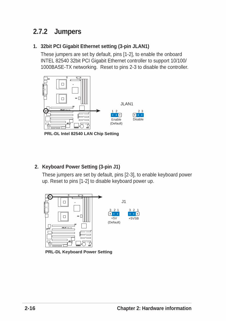
1. 32bit PCI Gigabit Ethernet setting (3-pin JLAN1)
These jumpers are set by default, pins [1-2], to enable the onboardINTEL 82540 32bit PCI Gigabit Ethernet controller to support 10/100/1000BASE-TX networking. Reset to pins 2-3 to disable the controller.
2.7.2 Jumpers
PRL-DL®
PRL-DL Intel 82540 LAN Chip Setting
JLAN1
(Default)Enable Disable
321 2
PRL-DL®
J1
PRL-DL Keyboard Power Setting
(Default)+5VSB+5V
12 3 23 1
2. Keyboard Power Setting (3-pin J1)These jumpers are set by default, pins [2-3], to enable keyboard powerup. Reset to pins [1-2] to disable keyboard power up.
ASUS PRL-DL motherboard user guide 2-17
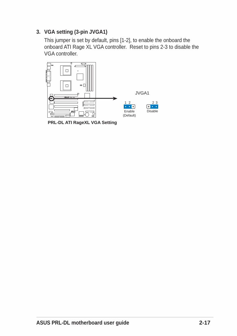
3. VGA setting (3-pin JVGA1)
This jumper is set by default, pins [1-2], to enable the onboard theonboard ATI Rage XL VGA controller. Reset to pins 2-3 to disable theVGA controller.
PRL-DL®
PRL-DL ATI RageXL VGA Setting
JVGA1
(Default)Enable Disable
321 2
2-18 Chapter 2: Hardware information
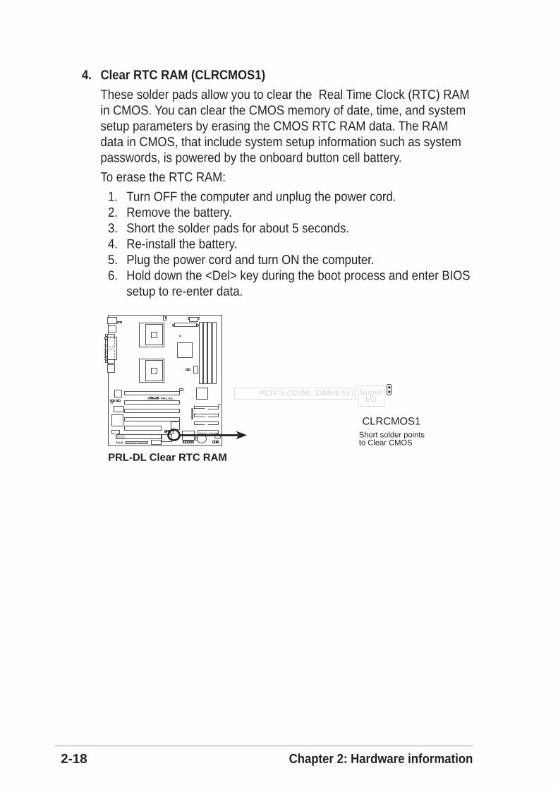
4. Clear RTC RAM (CLRCMOS1)
These solder pads allow you to clear the Real Time Clock (RTC) RAMin CMOS. You can clear the CMOS memory of date, time, and systemsetup parameters by erasing the CMOS RTC RAM data. The RAMdata in CMOS, that include system setup information such as systempasswords, is powered by the onboard button cell battery.
To erase the RTC RAM:
1. Turn OFF the computer and unplug the power cord.2. Remove the battery.3. Short the solder pads for about 5 seconds.4. Re-install the battery.5. Plug the power cord and turn ON the computer.6. Hold down the <Del> key during the boot process and enter BIOS
setup to re-enter data.
PRL-DL®
PRL-DL Clear RTC RAM
Short solder pointsto Clear CMOS
CLRCMOS1
PCIX-5 (32-bit, 33MHz 5V) SuperI/O
ASUS PRL-DL motherboard user guide 2-19
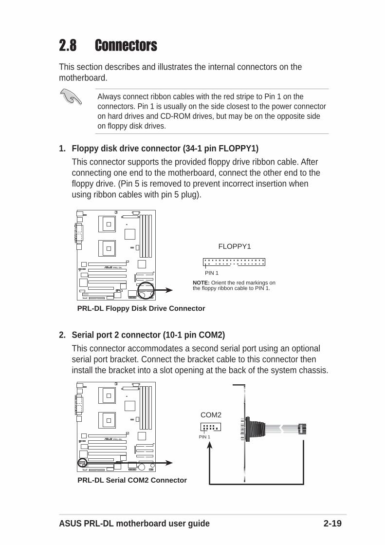
2.8 ConnectorsThis section describes and illustrates the internal connectors on themotherboard.
Always connect ribbon cables with the red stripe to Pin 1 on theconnectors. Pin 1 is usually on the side closest to the power connectoron hard drives and CD-ROM drives, but may be on the opposite sideon floppy disk drives.
1. Floppy disk drive connector (34-1 pin FLOPPY1)This connector supports the provided floppy drive ribbon cable. Afterconnecting one end to the motherboard, connect the other end to thefloppy drive. (Pin 5 is removed to prevent incorrect insertion whenusing ribbon cables with pin 5 plug).
2. Serial port 2 connector (10-1 pin COM2)
This connector accommodates a second serial port using an optionalserial port bracket. Connect the bracket cable to this connector theninstall the bracket into a slot opening at the back of the system chassis.
PRL-DL®
NOTE: Orient the red markings onthe floppy ribbon cable to PIN 1.
PRL-DL Floppy Disk Drive Connector
PIN 1
FLOPPY1
PRL-DL®
PRL-DL Serial COM2 Connector
PIN 1
COM2
2-20 Chapter 2: Hardware information
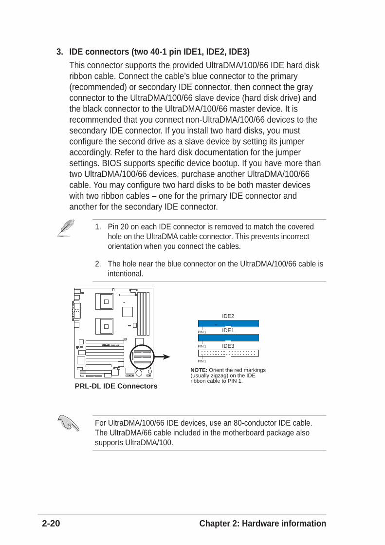
3. IDE connectors (two 40-1 pin IDE1, IDE2, IDE3)
This connector supports the provided UltraDMA/100/66 IDE hard diskribbon cable. Connect the cable’s blue connector to the primary(recommended) or secondary IDE connector, then connect the grayconnector to the UltraDMA/100/66 slave device (hard disk drive) andthe black connector to the UltraDMA/100/66 master device. It isrecommended that you connect non-UltraDMA/100/66 devices to thesecondary IDE connector. If you install two hard disks, you mustconfigure the second drive as a slave device by setting its jumperaccordingly. Refer to the hard disk documentation for the jumpersettings. BIOS supports specific device bootup. If you have more thantwo UltraDMA/100/66 devices, purchase another UltraDMA/100/66cable. You may configure two hard disks to be both master deviceswith two ribbon cables – one for the primary IDE connector andanother for the secondary IDE connector.
1. Pin 20 on each IDE connector is removed to match the coveredhole on the UltraDMA cable connector. This prevents incorrectorientation when you connect the cables.
2. The hole near the blue connector on the UltraDMA/100/66 cable isintentional.
For UltraDMA/100/66 IDE devices, use an 80-conductor IDE cable.The UltraDMA/66 cable included in the motherboard package alsosupports UltraDMA/100.
PRL-DL®
PRL-DL IDE Connectors
NOTE: Orient the red markings(usually zigzag) on the IDEribbon cable to PIN 1.
IDE1
IDE3
IDE2
PIN 1
PIN 1
PIN 1
ASUS PRL-DL motherboard user guide 2-21
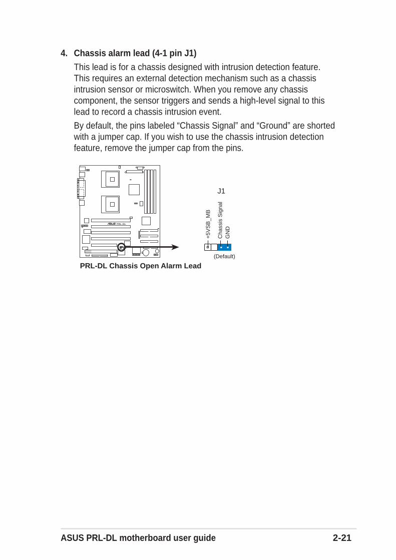
4. Chassis alarm lead (4-1 pin J1)
This lead is for a chassis designed with intrusion detection feature.This requires an external detection mechanism such as a chassisintrusion sensor or microswitch. When you remove any chassiscomponent, the sensor triggers and sends a high-level signal to thislead to record a chassis intrusion event.
By default, the pins labeled “Chassis Signal” and “Ground” are shortedwith a jumper cap. If you wish to use the chassis intrusion detectionfeature, remove the jumper cap from the pins.
PRL-DL®
PRL-DL Chassis Open Alarm Lead
J1
+5V
SB
_MB
Cha
ssis
Sig
nal
GN
D
(Default)
2-22 Chapter 2: Hardware information
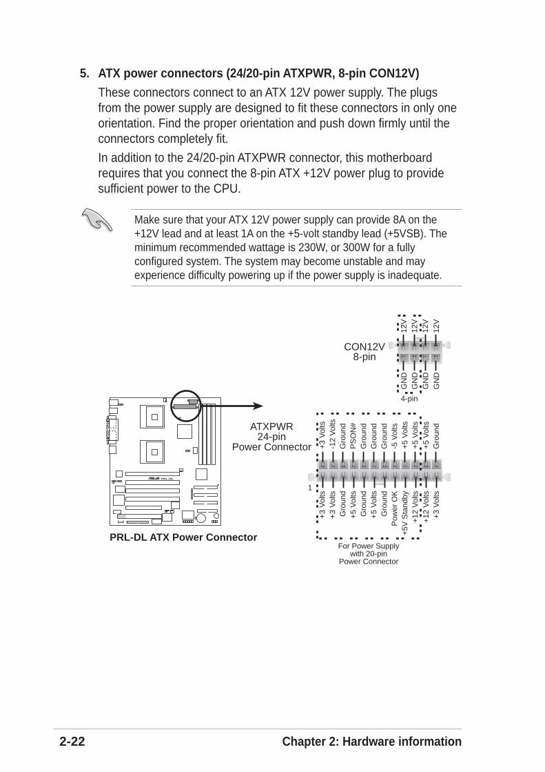
5. ATX power connectors (24/20-pin ATXPWR, 8-pin CON12V)
These connectors connect to an ATX 12V power supply. The plugsfrom the power supply are designed to fit these connectors in only oneorientation. Find the proper orientation and push down firmly until theconnectors completely fit.
In addition to the 24/20-pin ATXPWR connector, this motherboardrequires that you connect the 8-pin ATX +12V power plug to providesufficient power to the CPU.
Make sure that your ATX 12V power supply can provide 8A on the+12V lead and at least 1A on the +5-volt standby lead (+5VSB). Theminimum recommended wattage is 230W, or 300W for a fullyconfigured system. The system may become unstable and mayexperience difficulty powering up if the power supply is inadequate.
PRL-DL®
PRL-DL ATX Power ConnectorFor Power Supply
with 20-pinPower Connector
24-pinPower Connector
CON12V
+3
Vol
ts+
3 V
olts
Gro
und
+5
Vol
ts
+5
Vol
tsG
roun
d
Gro
und
Pow
er O
K+
5V S
tand
by+
12 V
olts
-5 V
olts
+5
Vol
ts
+3
Vol
ts-1
2 V
olts
Gro
und
Gro
und
Gro
und
PS
ON
#
Gro
und
+5
Vol
ts
+12
Vol
ts+
3 V
olts
+5
Vol
ts
1
Gro
undATXPWR
8-pin
GN
D12
VG
ND
12V
GN
D12
VG
ND
12V
4-pin
ASUS PRL-DL motherboard user guide 2-23
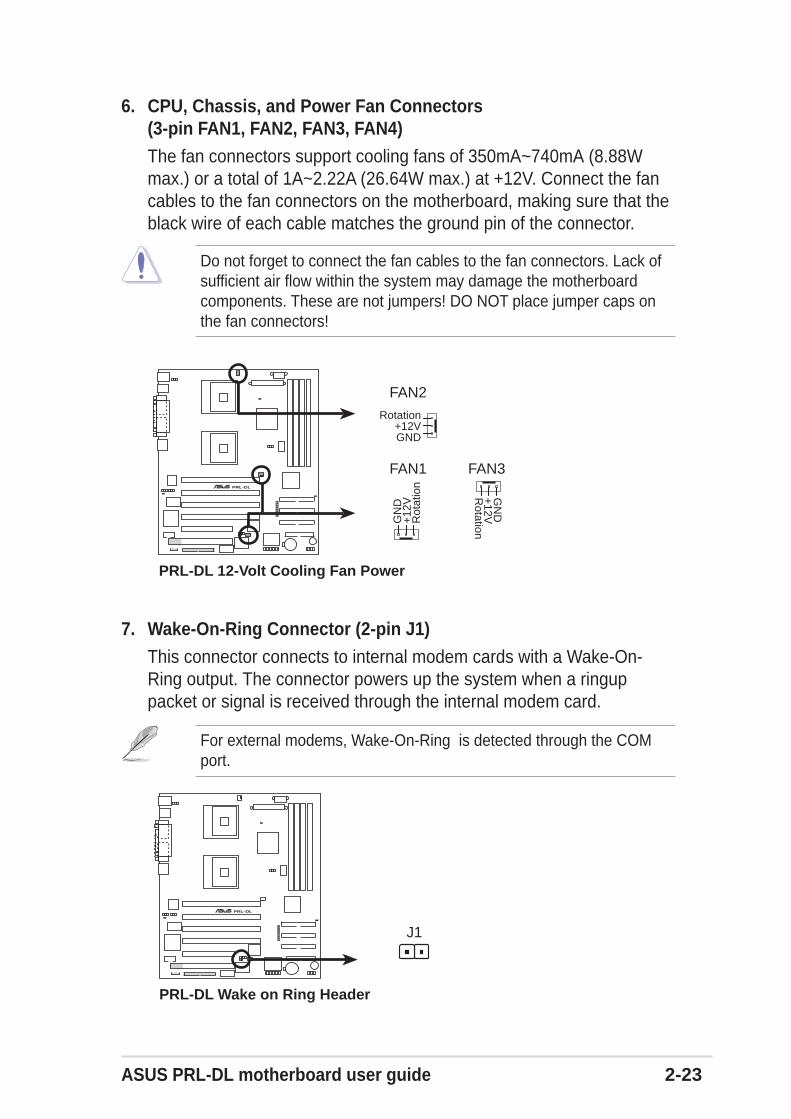
6. CPU, Chassis, and Power Fan Connectors(3-pin FAN1, FAN2, FAN3, FAN4)
The fan connectors support cooling fans of 350mA~740mA (8.88Wmax.) or a total of 1A~2.22A (26.64W max.) at +12V. Connect the fancables to the fan connectors on the motherboard, making sure that theblack wire of each cable matches the ground pin of the connector.
Do not forget to connect the fan cables to the fan connectors. Lack ofsufficient air flow within the system may damage the motherboardcomponents. These are not jumpers! DO NOT place jumper caps onthe fan connectors!
7. Wake-On-Ring Connector (2-pin J1)
This connector connects to internal modem cards with a Wake-On-Ring output. The connector powers up the system when a ringuppacket or signal is received through the internal modem card.
For external modems, Wake-On-Ring is detected through the COMport.
PRL-DL®
PRL-DL Wake on Ring Header
J1
PRL-DL®
PRL-DL 12-Volt Cooling Fan Power
FAN2
GND
Rotation+12V
FAN1 FAN3
GN
D
Rot
atio
n+
12V
GN
D
Rotation
+12V
2-24 Chapter 2: Hardware information
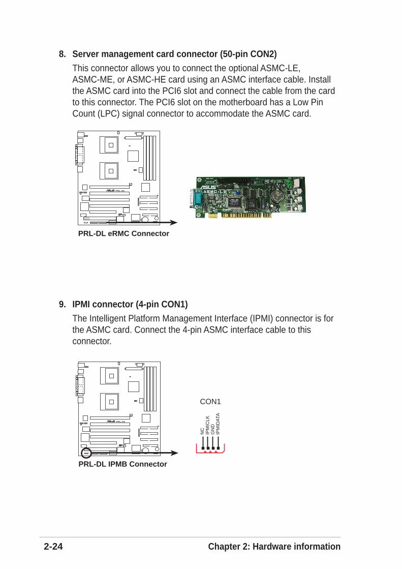
8. Server management card connector (50-pin CON2)
This connector allows you to connect the optional ASMC-LE,ASMC-ME, or ASMC-HE card using an ASMC interface cable. Installthe ASMC card into the PCI6 slot and connect the cable from the cardto this connector. The PCI6 slot on the motherboard has a Low PinCount (LPC) signal connector to accommodate the ASMC card.
9. IPMI connector (4-pin CON1)
The Intelligent Platform Management Interface (IPMI) connector is forthe ASMC card. Connect the 4-pin ASMC interface cable to thisconnector.
PRL-DL®
PRL-DL IPMB Connector
CON1
IPM
IDA
TAG
ND
IPM
ICLK
NC
PRL-DL®
PRL-DL eRMC Connector
ASUS PRL-DL motherboard user guide 2-25
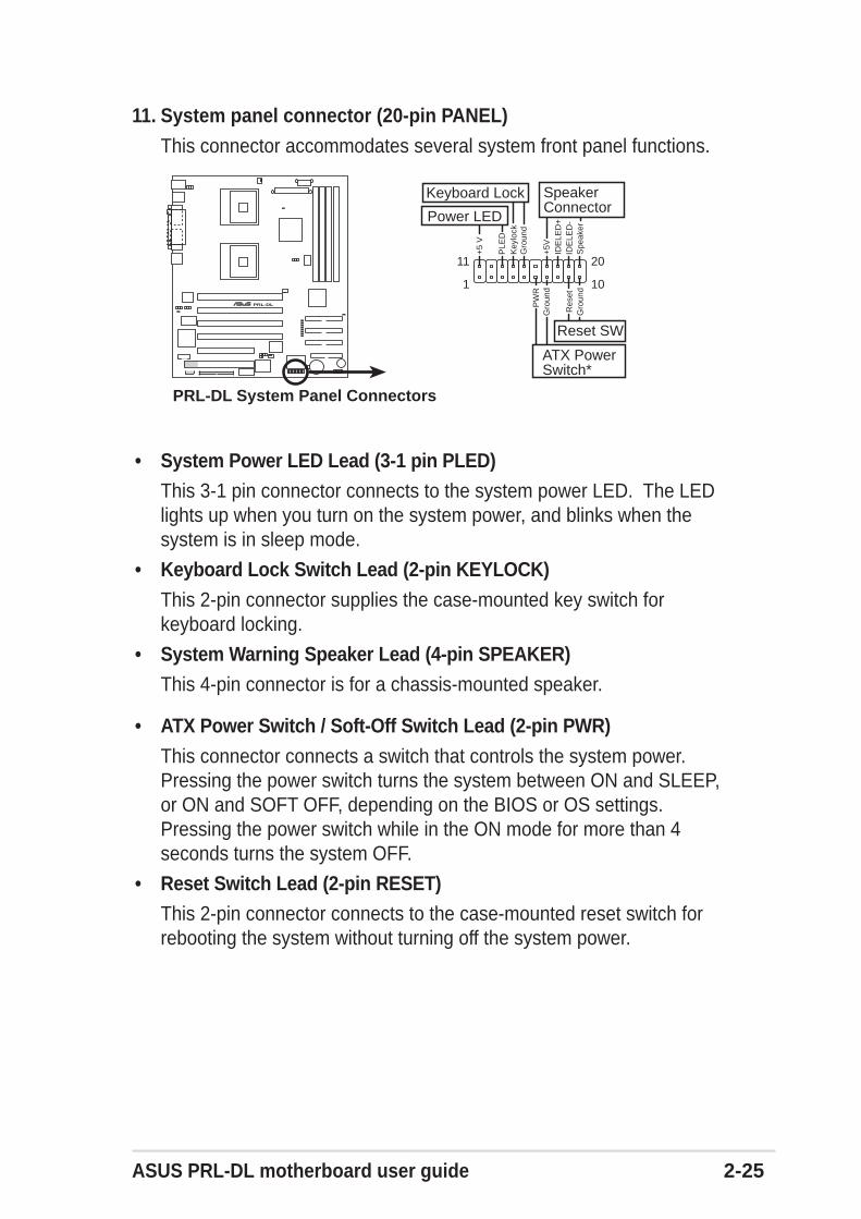
• System Power LED Lead (3-1 pin PLED)This 3-1 pin connector connects to the system power LED. The LEDlights up when you turn on the system power, and blinks when thesystem is in sleep mode.
• Keyboard Lock Switch Lead (2-pin KEYLOCK)
This 2-pin connector supplies the case-mounted key switch forkeyboard locking.
• System Warning Speaker Lead (4-pin SPEAKER)This 4-pin connector is for a chassis-mounted speaker.
• ATX Power Switch / Soft-Off Switch Lead (2-pin PWR)
This connector connects a switch that controls the system power.Pressing the power switch turns the system between ON and SLEEP,or ON and SOFT OFF, depending on the BIOS or OS settings.Pressing the power switch while in the ON mode for more than 4seconds turns the system OFF.
• Reset Switch Lead (2-pin RESET)This 2-pin connector connects to the case-mounted reset switch forrebooting the system without turning off the system power.
11. System panel connector (20-pin PANEL)
This connector accommodates several system front panel functions.
PRL-DL®
PRL-DL System Panel Connectors
PLE
D
PW
R
+5
V
Key
lock
+5V Spe
aker
SpeakerConnector
Power LED
Gro
und
Reset SW
Gro
und
Res
etID
ELE
D+
IDE
LED
-
Gro
und
Keyboard Lock
ATX PowerSwitch*
1
11
10
20
2-26 Chapter 2: Hardware information
IDE2
FLOPPY1
ASUSASIC
with HardwareMonitor
4MbitFlashBIOS
PRL-DL
PCI64-1 (64-bit, 33MHz 3V)
FAN3
ASUS PANEL1
ATIRAGE XL
VGAController
JVGA1
BUZZ1
CON1
PCI2 (32-bit, 33MHz 5V)
ServerWorks CSB6
South Bridge
®
30.7
cm (
12.0
8in)
®
COM2
SuperI/O
J3
CR2032 3VLithium Cell
CMOS Power
mP
GA
604
mP
GA
604
DD
R D
IMM
1 (6
4/72
bit,
184
-pin
mod
ule)
0 1
DD
R D
IMM
2 (6
4/72
bit,
184
-pin
mod
ule)
2 3
DD
R D
IMM
3 (6
4/72
bit,
184
-pin
mod
ule)
4 5
DD
R D
IMM
4 (6
4/72
bit,
184
-pin
mod
ule)
6 7
CON2
J1
SW2
FAN1
FAN2
JLAN1
JFSB1
VGA RAM
CLRCMOS1
Intel82540GigabitEthernet
ATX_POWER
CON12V
SW1
POWERLED1
LED8
STBYLED1
CPULED1
LED7LED6LED5LED4LED3LED2LED1
USB0USB1
COM1
PAR
AL
LE
L P
OR
T
VGA
RJ-45
PS/2T: MouseB: Keyboard
26.67.cm (10.4in)
PCI1 (32-bit, 33MHz 5V)
IDE1
IDE3
ServerWorksGCSL
North Bridge
®
J1
PCI64-2 (64-bit, 33MHz 3V)
PCI64-3 (64-bit, 33MHz 3V)
PCI64-4 (64-bit, 33MHz 3V)
USB2.3
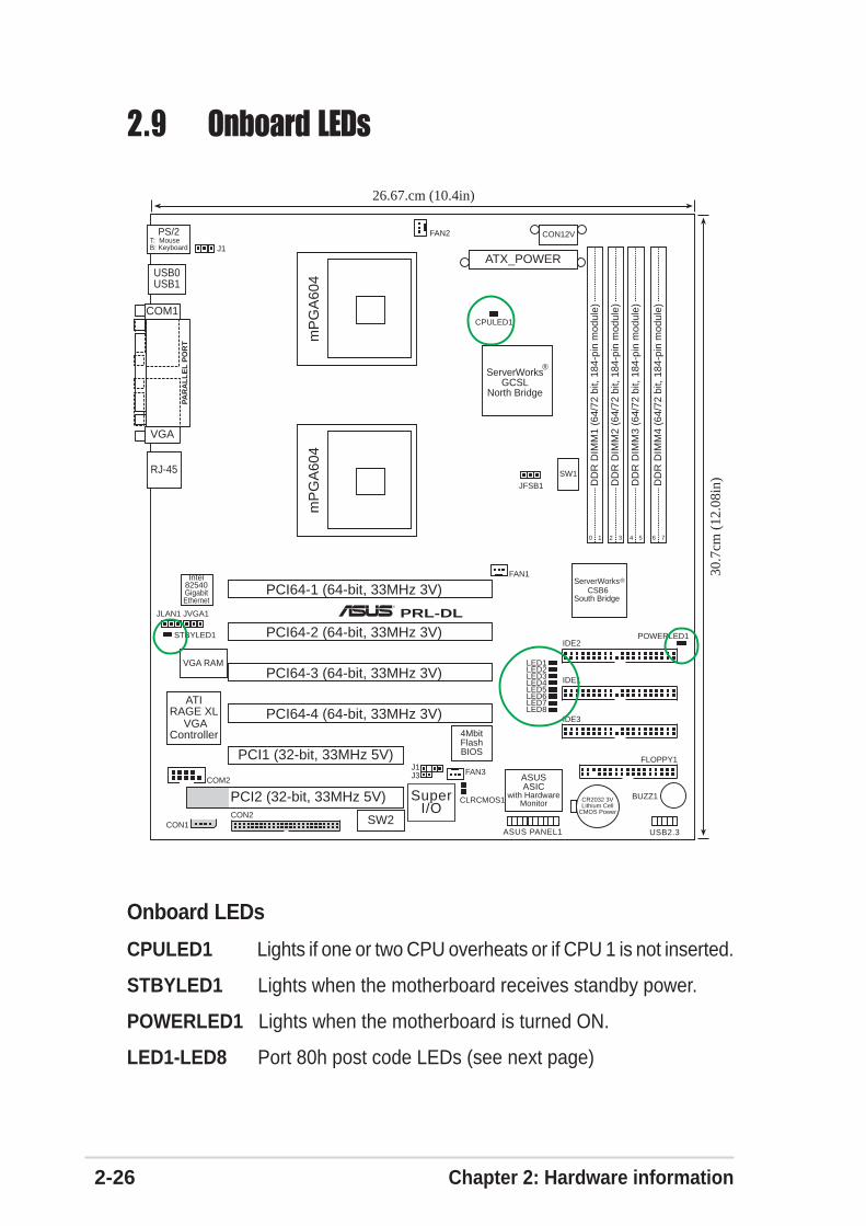
Onboard LEDs
CPULED1 Lights if one or two CPU overheats or if CPU 1 is not inserted.
STBYLED1 Lights when the motherboard receives standby power.
POWERLED1 Lights when the motherboard is turned ON.
LED1-LED8 Port 80h post code LEDs (see next page)
2.9 Onboard LEDs
ASUS PRL-DL motherboard user guide 2-27
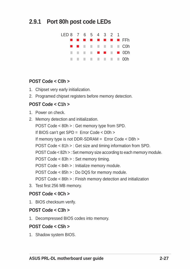
2.9.1 Port 80h post code LEDs
POST Code < C0h >
1. Chipset very early initialization.
2. Programed chipset registers before memory detection.
POST Code < C1h >
1. Power on check.
2. Memory detection and initialization.
POST Code < 80h > : Get memory type from SPD.
If BIOS can’t get SPD = Error Code < D0h >
If memory type is not DDR-SDRAM = Error Code < D8h >
POST Code < 81h > : Get size and timing information from SPD.
POST Code < 82h > : Set memory size according to each memory module.
POST Code < 83h > : Set memory timing.
POST Code < 84h > : Initialize memory module.
POST Code < 85h > : Do DQS for memory module.
POST Code < 86h > : Finish memory detection and initialization
3. Test first 256 MB memory.
POST Code < 0Ch >
1. BIOS checksum verify.
POST Code < C3h >
1. Decompressed BIOS codes into memory.
POST Code < C5h >
1. Shadow system BIOS.
8 7 6 5 4 3 2 1FFhC0h0Dh
00h
LED
2-28 Chapter 2: Hardware information
2. Disabled CPU cache.
3. Check if go to BOOTBLOCK POST.
POST Code < 05h >
1. Blank out the video screen.
2. Initialized the keyboard.
POST Code < 07h >
1. Used walking 1's algorithm to check out interface to CMOS circuitry.
2. Also set real-time clock power status. Then check for override.
POST Code < 09h >
1. Programed chipset register to default value according to ROMTABLE.
2. early initialize CPU.
3. Initialized APIC.
4. Set A20 off.
POST Code < 0Ah >
1. Initialized int. vectors (0-77h) to the spurious interrupt handler. Theninitialize 00h-1fh to their proper places.
POST Code < 0Bh >
1. Checked normal ISA CMOS checksum and battery. If it fails, we load themanufacturing defaults.
2. Chipset very early PM initialization, change SMBASE for CPU and moveSMM code.
3. PMM initialization.
4. Disable all memory caching then enable E800 and F000 segementcaching.
5. PnP early initialization.
6. BBS initialization.
POST Code < 0Ch >
1. Initialize the keyboard controller and set up all of the 40: area data.
2. Load CPU micro-code update if BIOS updated option is enable.
ASUS PRL-DL motherboard user guide 2-29
POST Code < 0Dh >
1. Programed CPU MTRR. Measure CPU speed and save CPU speed.
2. Initialized the video, whether it is mono, color or EGA/VGA. After initialize,shrink the VGA BIOS.
3. If no video found in this stage, beep a warning sound.
POST Code < 0Eh >
1. Set A20 on.
2. Showed HP Logo or Award Logo
3. Showed CPU type on screen.
POST Code < 14h >
1. Test 8254 Channel 2.
POST Code < 18h >
1. Test 8259 functionality.
POST Code < 30h >
1. Disabled D0/D1 command to KBC, wait for command accepted.
2. Special KBC Initialization (set KBC to PS2 mode).
3. Sizing base memory (0-640K) and extended memory starting at just overthe 1M boundary.
Will continue until fail to read what was written or come to the 3GB boundary.
POST Code < 31h >
1. Set CPU MTRR for address above 1MB.
2. Cleared base memory.
3. Build UMB structure.
4. Initialized USB.
5. Erased all of memory above 1MB if QUICK_POST is disabled.
POST Code < 32h >
1. Displayed AWARD PNP message. (Award_PnP_Msg)
2. Initialized onboard SuperIO.
a. Early IDE chip initialize.
b. Programed SuperIO chip.
2-30 Chapter 2: Hardware information
POST Code < 3Dh >
1. Initialize and install mouse and 40: area stuff...
2. Set extended memory size.
3. Save EXT_MEM_Size_MB in G_RAM.
4. Expanded ACPI table into memory.
5. Setup ACPITable and ACPINVS Size.
6. According to length of ACPI table to decrease Ext_MEM_FOUND,EXT_MEMORY.
7. After extended memory test, copy all ACPI tables to ACPI reclaim area(just below top of extended memory, see ATBASE INT15 function 0e820h).
Then fill in physical address and checksum for all ACPI tables.
8. Get extended memory size and set size for E801h.
9. Check USB Legacy Mode.
10. Installed Mouse.
POST Code < 3Eh >
1. Do external cache sizing if it cannot be detected correctly after onboardmemory configuration (just return).
POST Code < 41h >
1. Programed chipset registers accroding to menuitem setting.
2. Installed floppy devices.
POST Code < 42h >
1. Installed hard disks.
POST Code < 45h >
1. Initialized and installed co-processor.
POST Code < 4Eh >
1. Checked whether the keyboard is locked or not.
2. Report USB Keyboard.
3. Translate HaltOn_Item value to tell whether individual catagory errorshould be reported or not.
ASUS PRL-DL motherboard user guide 2-31
POST Code < 4Fh >
1. Power management initialization.
2. Verify password.
POST Code < 50h >
1. Write all of CMOS back to RAM.
POST Code < 52h >
1. Do whatever needs to do before PCI ROM initialization.
2. Shadow adaptor card's ROM.
3. Do whatever need to do after PCI ROM initialization.
4. Build BBS Table.
5. Set segement f000 to shadow write.
6. Save SCSI card information.
7. Set segement f000 to shadow read.
8. Enable parity and NMI.
9. Enable IRQ 12 if PS2 mouse hot plug.
10. Enable BIOS Setup.
POST Code < 60h >
1. Set up PS2.
POST Code < 61h >
1. Enable L1/L2 cache according to BIOS setup option.
2. Chipset final initialization.
3. Chipset power management final initialization.
4. Show system configuration.
POST Code < 62h >
1. Force NUM-LOCK on 101-key keyboard.
2. Clear LEd first.
3. Set NumLock status according BIOS setup.
4. Set Typematic rate according BIOS setup.
2-32 Chapter 2: Hardware information
POST Code < 63h >
1. Send D2 command following with dummy code 80h for PM to check powerdown.
2. PNP final initialization.
3. Enable Boot Menu.
4. Check RTC clock data (hour, minute and second), if error set register Ato default value.
5. Set up low stack.
6. Clear any pending keystroke and KB queue buffer.
7. Clear garbage in base memory except BIOS data.
8. Set segment EC00 to EFFF shadow read/write.
9. Set segment EC00 to EFFF shadow read/write.
10. Set A20 off.
POST Code < ffh >
1. INT 19h (system boot).
Chapter 3
Powering up
This chapter describes the power upsequence and gives information on theBIOS beep codes.
ASUS PRL-DL motherboard
Chapter summary
3.1 Starting up for the first time.......................... 3-1
3.2 Powering off the computer ........................... 3-2
ASUS PRL-DL motherboard user guide 3-1
3.1 Starting up for the first time1. After making all the connections, replace the system case cover.
2. Be sure that all switches are off.
3. Connect the power cord to the power connector at the back of the systemchassis.
4. Connect the power cord to a power outlet that is equipped with a surgeprotector.
5. Turn on the devices in the following order:
a. Monitor
b. External SCSI devices (starting with the last device on the chain)
c. System power (if you are using an ATX power supply, you need toswitch on the power supply as well as press the ATX power switch onthe front of the chassis).
6. After applying power, the power LED on the system front panel case lightsup. For ATX power supplies, the system LED lights up when you press theATX power switch. If your monitor complies with “green” standards or if ithas a “power standby” feature, the monitor LED may light up or switchbetween orange and green after the system LED turns on. The systemthen runs the power-on tests. While the tests are running, the BIOS beepsor additional messages appear on the screen. If you do not see anythingwithin 30 seconds from the time you turned on the power, the system mayhave failed a power-on test. Check the jumper settings and connections orcall your retailer for assistance.
Award BIOS Beep Codes
Beep Meaning
One short beep when No error during POSTdisplaying logo
Long beeps in an endless loop No DRAM installed or detected
One long beep followed by Video card not found or video cardthree short beeps memory bad
High frequency beeps when CPU overheated;system is working System running at a lower frequency
7. At power on, hold down <Delete> to enter BIOS Setup. Follow theinstructions in Chapter 4.
3-2 Chapter 3: Powering up
3.2 Powering off the computerYou must first exit the operating system and shut down the system beforeswitching off the power. For ATX power supplies, you can press the ATXpower switch after exiting or shutting down the operating system. If youuse Windows 98SE/2000/XP, click the Start button, click Shut Down, thenclick the OK button to shut down the computer. The power supply shouldturn off after Windows shuts down.
The message “You can now safely turn off your computer” does notappear when shutting down with ATX power supplies.
Chapter 4
BIOS setup
This chapter tells how to change systemsettings through the BIOS Setup menus.Detailed descriptions of the BIOSparameters are also provided.
ASUS PRL-DL motherboard
Chapter summary
4.1 Managing and updating your BIOS .............. 4-1
4.2 BIOS Setup program...................................... 4-5
4.3 Main Menu ...................................................... 4-8
4.4 Advanced Menu ........................................... 4-15
4.5 Power Menu .................................................. 4-22
4.6 Boot Menu .................................................... 4-27
4.7 Server Menu ................................................. 4-29
4.8 Exit Menu ...................................................... 4-30
ASUS PRL-DL motherboard user guide 4-1
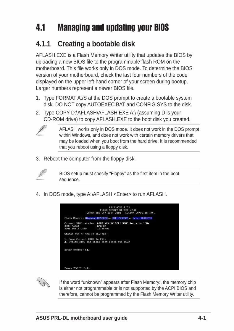
4.1.1 Creating a bootable diskAFLASH.EXE is a Flash Memory Writer utility that updates the BIOS byuploading a new BIOS file to the programmable flash ROM on themotherboard. This file works only in DOS mode. To determine the BIOSversion of your motherboard, check the last four numbers of the codedisplayed on the upper left-hand corner of your screen during bootup.Larger numbers represent a newer BIOS file.
1. Type FORMAT A:/S at the DOS prompt to create a bootable systemdisk. DO NOT copy AUTOEXEC.BAT and CONFIG.SYS to the disk.
2. Type COPY D:\AFLASH\AFLASH.EXE A:\ (assuming D is yourCD-ROM drive) to copy AFLASH.EXE to the boot disk you created.
BIOS setup must specify “Floppy” as the first item in the bootsequence.
4. In DOS mode, type A:\AFLASH <Enter> to run AFLASH.
If the word “unknown” appears after Flash Memory:, the memory chipis either not programmable or is not supported by the ACPI BIOS andtherefore, cannot be programmed by the Flash Memory Writer utility.
AFLASH works only in DOS mode. It does not work in the DOS promptwithin Windows, and does not work with certain memory drivers thatmay be loaded when you boot from the hard drive. It is recommendedthat you reboot using a floppy disk.
3. Reboot the computer from the floppy disk.
4.1 Managing and updating your BIOS
4-2 Chapter 4: BIOS Setup
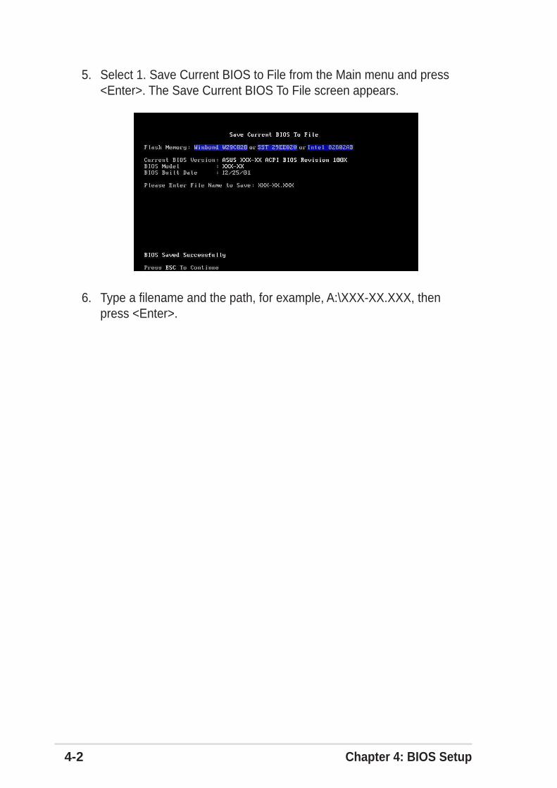
5. Select 1. Save Current BIOS to File from the Main menu and press<Enter>. The Save Current BIOS To File screen appears.
6. Type a filename and the path, for example, A:\XXX-XX.XXX, thenpress <Enter>.
ASUS PRL-DL motherboard user guide 4-3
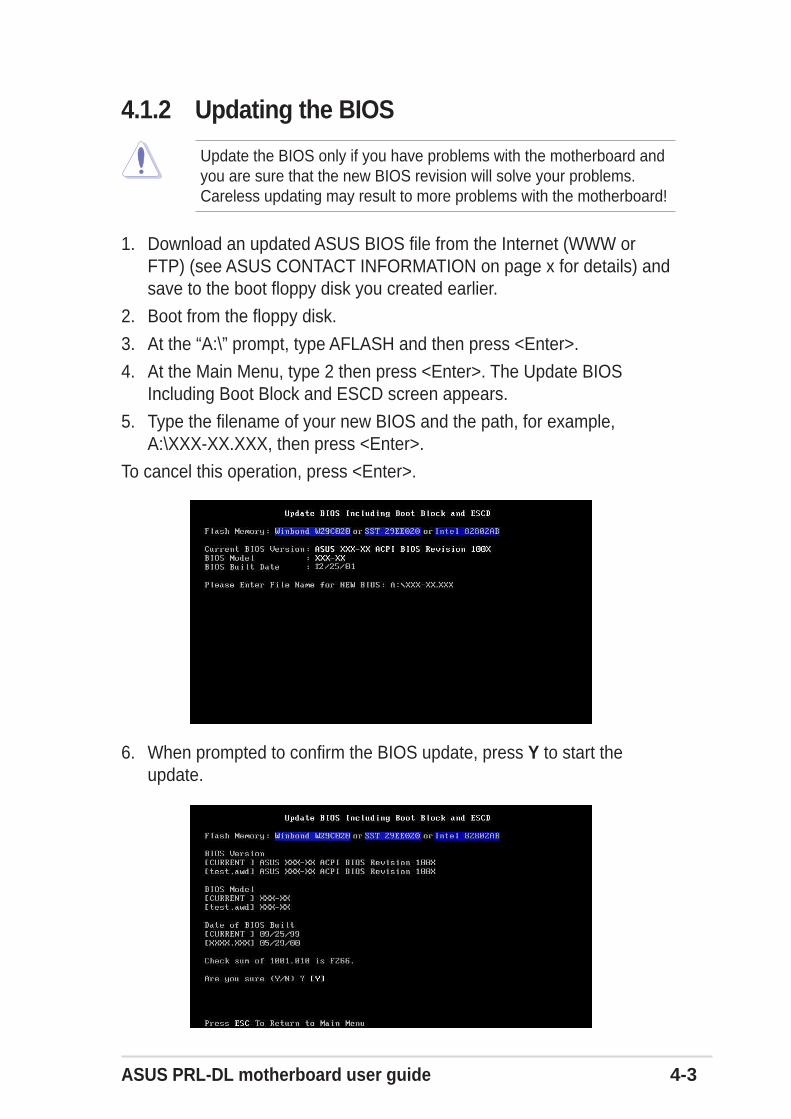
1. Download an updated ASUS BIOS file from the Internet (WWW orFTP) (see ASUS CONTACT INFORMATION on page x for details) andsave to the boot floppy disk you created earlier.
2. Boot from the floppy disk.
3. At the “A:\” prompt, type AFLASH and then press <Enter>.
4. At the Main Menu, type 2 then press <Enter>. The Update BIOSIncluding Boot Block and ESCD screen appears.
5. Type the filename of your new BIOS and the path, for example,A:\XXX-XX.XXX, then press <Enter>.
To cancel this operation, press <Enter>.
6. When prompted to confirm the BIOS update, press Y to start theupdate.
Update the BIOS only if you have problems with the motherboard andyou are sure that the new BIOS revision will solve your problems.Careless updating may result to more problems with the motherboard!
4.1.2 Updating the BIOS
4-4 Chapter 4: BIOS Setup
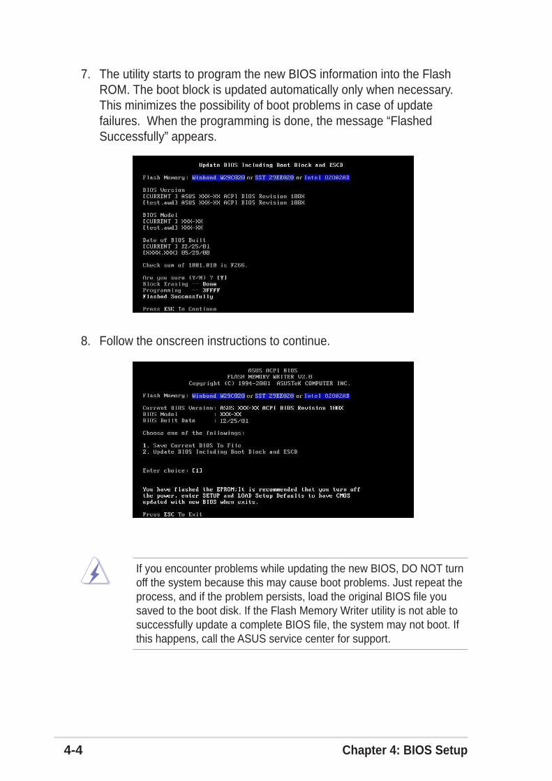
7. The utility starts to program the new BIOS information into the FlashROM. The boot block is updated automatically only when necessary.This minimizes the possibility of boot problems in case of updatefailures. When the programming is done, the message “FlashedSuccessfully” appears.
8. Follow the onscreen instructions to continue.
If you encounter problems while updating the new BIOS, DO NOT turnoff the system because this may cause boot problems. Just repeat theprocess, and if the problem persists, load the original BIOS file yousaved to the boot disk. If the Flash Memory Writer utility is not able tosuccessfully update a complete BIOS file, the system may not boot. Ifthis happens, call the ASUS service center for support.
ASUS PRL-DL motherboard user guide 4-5
4.2 BIOS Setup programThis motherboard supports a programmable Flash ROM that you canupdate using the provided utility described in section “4.1 Managing andupdating your BIOS.”
Use the BIOS Setup program when you are installing a motherboard,reconfiguring your system, or prompted to “Run Setup”. This sectionexplains how to configure your system using this utility.
Even if you are not prompted to use the Setup program, you may want tochange the configuration of your computer in the future. For example, youmay want to enable the security password feature or make changes to thepower management settings. This requires you to reconfigure your systemusing the BIOS Setup program so that the computer can recognize thesechanges and record them in the CMOS RAM of the Flash ROM.
The Flash ROM on the motherboard stores the Setup utility. When youstart up the computer, the system provides you with the opportunity to runthis program. Press <Delete> during the Power-On Self Test (POST) toenter the Setup utility, otherwise, POST continues with its test routines.
If you wish to enter Setup after POST, restart the system by pressing<Ctrl> + <Alt> + <Delete>, or by pressing the reset button on the systemchassis. You can also restart by turning the system off and then back on.Do this last option only if the first two failed.
The Setup program is designed to make it as easy to use as possible. It isa menu-driven program, which means you can scroll through the varioussub-menus and make your selections among the predetermined choices.
Because the BIOS software is constantly being updated, the followingBIOS setup screens and descriptions are for reference purposes only,and may not exactly match what you see on your screen.
4-6 Chapter 4: BIOS Setup
4.2.1 BIOS menu barThe top of the screen has a menu bar with the following selections:
MAIN Use this menu to make changes to the basic systemconfiguration.
ADVANCED Use this menu to enable and make changes to theadvanced features.
POWER Use this menu to configure power management features.
BOOT Use this menu to configure the default system device usedto locate and load the Operating System.
SERVER Use this menu to set server-related items
EXIT Use this menu to exit the current menu or to exit the Setupprogram.
To access the menu bar items, press the right or left arrow key on thekeyboard until the desired item is highlighted.
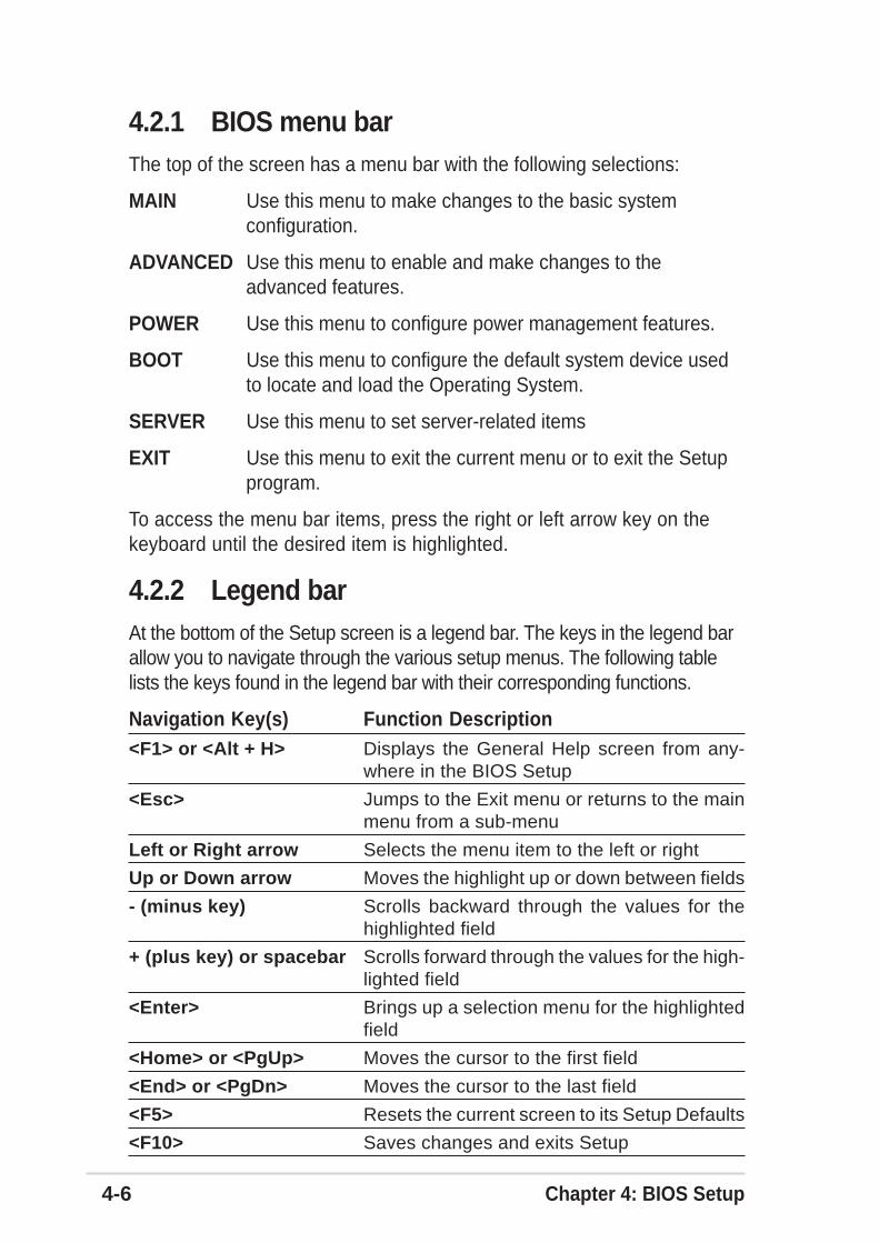
4.2.2 Legend barAt the bottom of the Setup screen is a legend bar. The keys in the legend barallow you to navigate through the various setup menus. The following tablelists the keys found in the legend bar with their corresponding functions.
Navigation Key(s) Function Description<F1> or <Alt + H> Displays the General Help screen from any-
where in the BIOS Setup
<Esc> Jumps to the Exit menu or returns to the mainmenu from a sub-menu
Left or Right arrow Selects the menu item to the left or right
Up or Down arrow Moves the highlight up or down between fields
- (minus key) Scrolls backward through the values for thehighlighted field
+ (plus key) or spacebar Scrolls forward through the values for the high-lighted field
<Enter> Brings up a selection menu for the highlightedfield
<Home> or <PgUp> Moves the cursor to the first field
<End> or <PgDn> Moves the cursor to the last field
<F5> Resets the current screen to its Setup Defaults
<F10> Saves changes and exits Setup
ASUS PRL-DL motherboard user guide 4-7
General helpIn addition to the Item Specific Help window, the BIOS setup program alsoprovides a General Help screen. You may launch this screen from anymenu by simply pressing <F1> or the <Alt> + <H> combination. TheGeneral Help screen lists the legend keys and their correspondingfunctions.
Saving changes and exiting the Setup programSee “4.8 Exit Menu” for detailed information on saving changes and exitingthe setup program.
Scroll barWhen a scroll bar appears to the right of a help window, it indicates thatthere is more information to be displayed that will not fit in the window. Use<PgUp> and <PgDn> or the up and down arrow keys to scroll through theentire help document. Press <Home> to display the first page, press<End> to go to the last page. To exit the help window, press <Enter> or<Esc>.
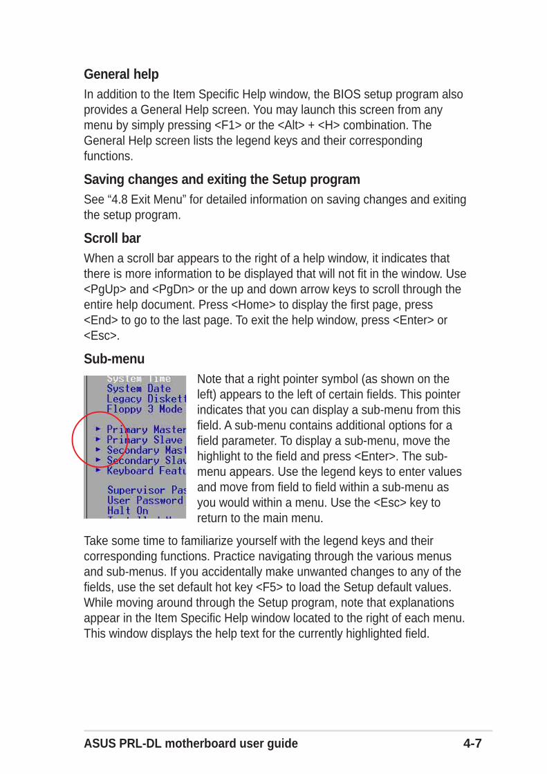
Sub-menuNote that a right pointer symbol (as shown on theleft) appears to the left of certain fields. This pointerindicates that you can display a sub-menu from thisfield. A sub-menu contains additional options for afield parameter. To display a sub-menu, move thehighlight to the field and press <Enter>. The sub-menu appears. Use the legend keys to enter valuesand move from field to field within a sub-menu asyou would within a menu. Use the <Esc> key toreturn to the main menu.
Take some time to familiarize yourself with the legend keys and theircorresponding functions. Practice navigating through the various menusand sub-menus. If you accidentally make unwanted changes to any of thefields, use the set default hot key <F5> to load the Setup default values.While moving around through the Setup program, note that explanationsappear in the Item Specific Help window located to the right of each menu.This window displays the help text for the currently highlighted field.
4-8 Chapter 4: BIOS Setup
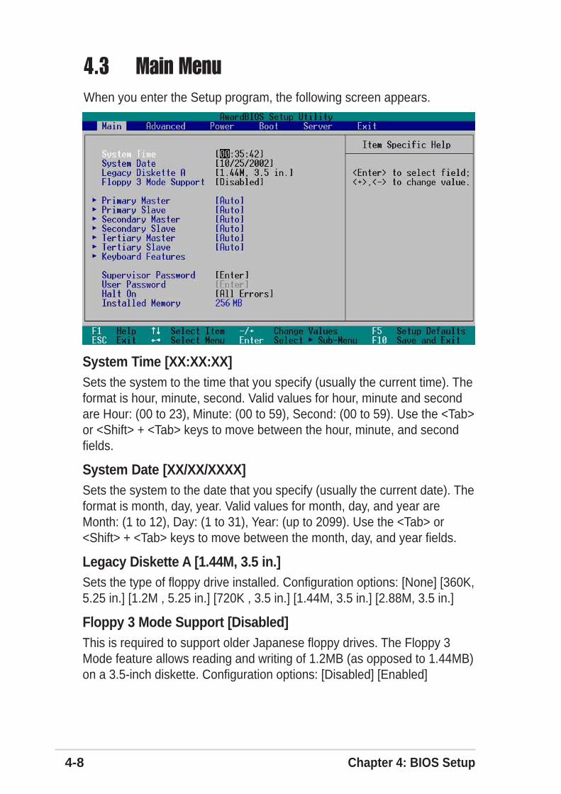
System Time [XX:XX:XX]Sets the system to the time that you specify (usually the current time). Theformat is hour, minute, second. Valid values for hour, minute and secondare Hour: (00 to 23), Minute: (00 to 59), Second: (00 to 59). Use the <Tab>or <Shift> + <Tab> keys to move between the hour, minute, and secondfields.
System Date [XX/XX/XXXX]Sets the system to the date that you specify (usually the current date). Theformat is month, day, year. Valid values for month, day, and year areMonth: (1 to 12), Day: (1 to 31), Year: (up to 2099). Use the <Tab> or<Shift> + <Tab> keys to move between the month, day, and year fields.
Legacy Diskette A [1.44M, 3.5 in.]Sets the type of floppy drive installed. Configuration options: [None] [360K,5.25 in.] [1.2M , 5.25 in.] [720K , 3.5 in.] [1.44M, 3.5 in.] [2.88M, 3.5 in.]
Floppy 3 Mode Support [Disabled]This is required to support older Japanese floppy drives. The Floppy 3Mode feature allows reading and writing of 1.2MB (as opposed to 1.44MB)on a 3.5-inch diskette. Configuration options: [Disabled] [Enabled]
4.3 Main MenuWhen you enter the Setup program, the following screen appears.
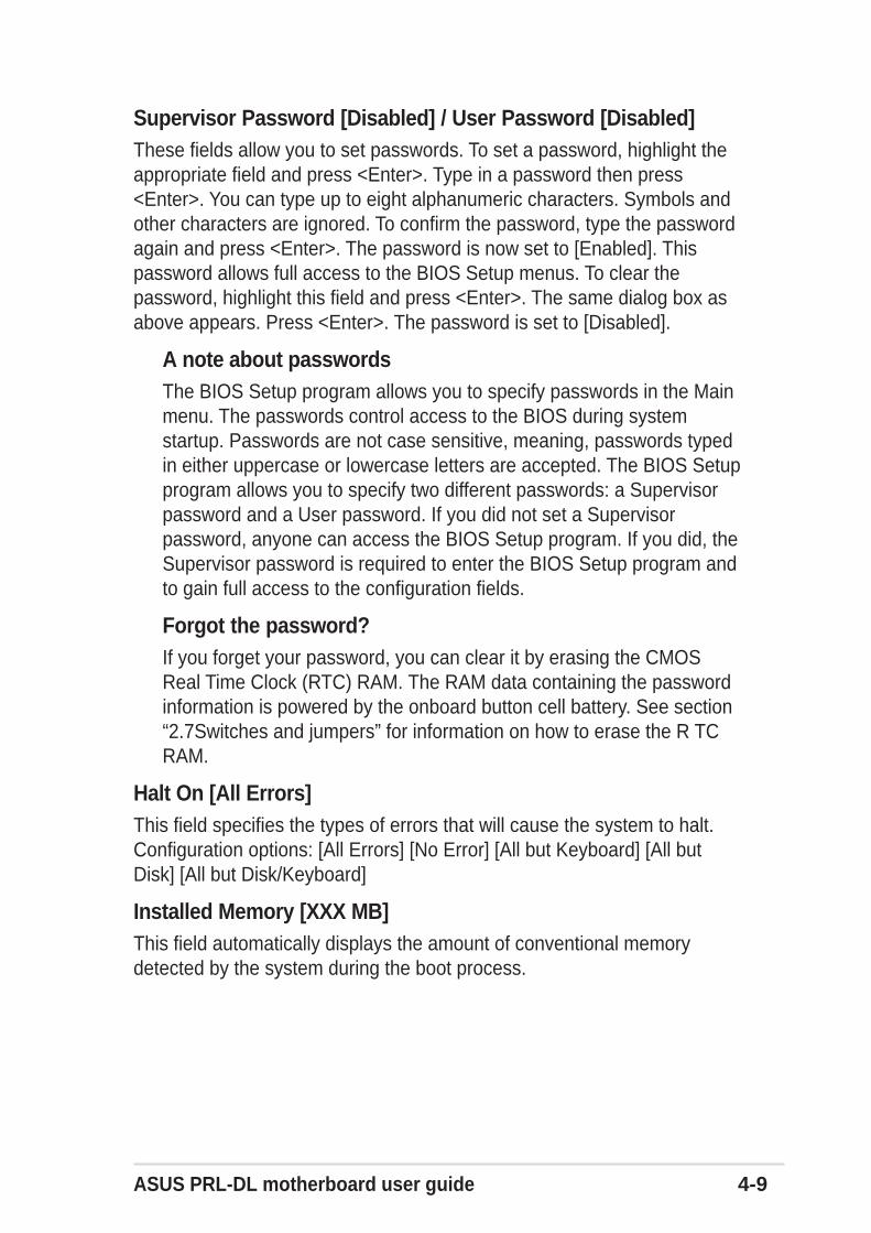
ASUS PRL-DL motherboard user guide 4-9
Supervisor Password [Disabled] / User Password [Disabled]These fields allow you to set passwords. To set a password, highlight theappropriate field and press <Enter>. Type in a password then press<Enter>. You can type up to eight alphanumeric characters. Symbols andother characters are ignored. To confirm the password, type the passwordagain and press <Enter>. The password is now set to [Enabled]. Thispassword allows full access to the BIOS Setup menus. To clear thepassword, highlight this field and press <Enter>. The same dialog box asabove appears. Press <Enter>. The password is set to [Disabled].
A note about passwordsThe BIOS Setup program allows you to specify passwords in the Mainmenu. The passwords control access to the BIOS during systemstartup. Passwords are not case sensitive, meaning, passwords typedin either uppercase or lowercase letters are accepted. The BIOS Setupprogram allows you to specify two different passwords: a Supervisorpassword and a User password. If you did not set a Supervisorpassword, anyone can access the BIOS Setup program. If you did, theSupervisor password is required to enter the BIOS Setup program andto gain full access to the configuration fields.
Forgot the password?If you forget your password, you can clear it by erasing the CMOSReal Time Clock (RTC) RAM. The RAM data containing the passwordinformation is powered by the onboard button cell battery. See section“2.7Switches and jumpers” for information on how to erase the R TCRAM.
Halt On [All Errors]This field specifies the types of errors that will cause the system to halt.Configuration options: [All Errors] [No Error] [All but Keyboard] [All butDisk] [All but Disk/Keyboard]
Installed Memory [XXX MB]This field automatically displays the amount of conventional memorydetected by the system during the boot process.
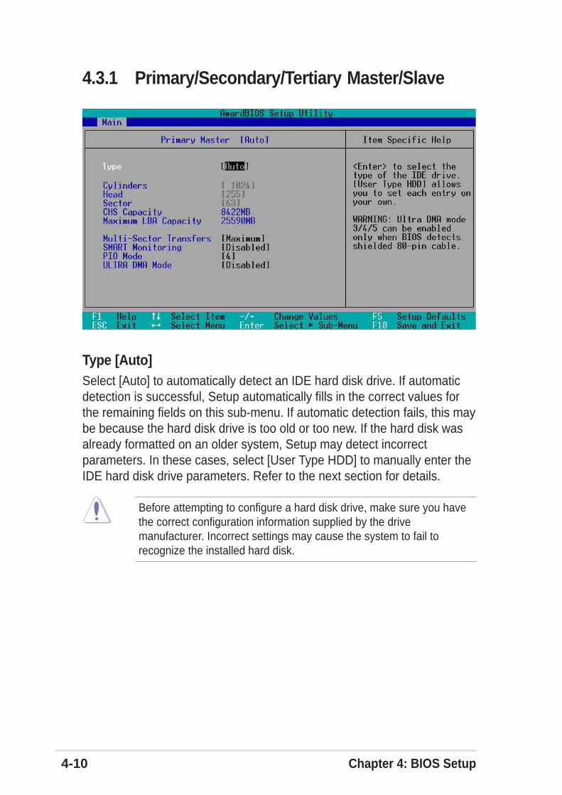
4-10 Chapter 4: BIOS Setup
4.3.1 Primary/Secondary/Tertiary Master/Slave
Type [Auto]Select [Auto] to automatically detect an IDE hard disk drive. If automaticdetection is successful, Setup automatically fills in the correct values forthe remaining fields on this sub-menu. If automatic detection fails, this maybe because the hard disk drive is too old or too new. If the hard disk wasalready formatted on an older system, Setup may detect incorrectparameters. In these cases, select [User Type HDD] to manually enter theIDE hard disk drive parameters. Refer to the next section for details.
Before attempting to configure a hard disk drive, make sure you havethe correct configuration information supplied by the drivemanufacturer. Incorrect settings may cause the system to fail torecognize the installed hard disk.
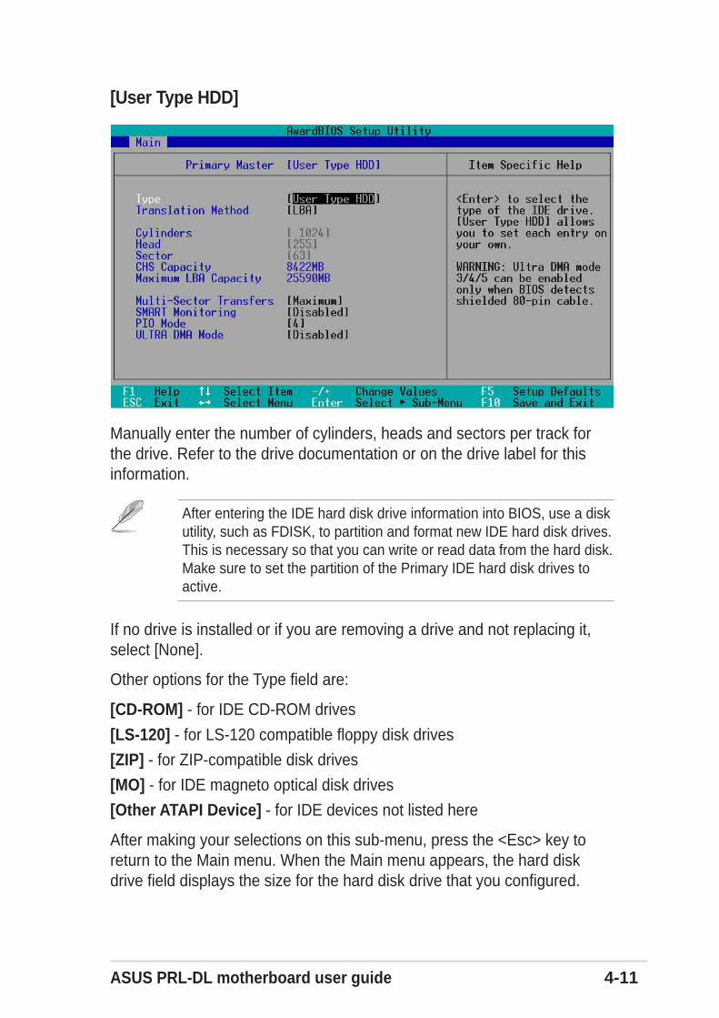
ASUS PRL-DL motherboard user guide 4-11
If no drive is installed or if you are removing a drive and not replacing it,select [None].
Other options for the Type field are:
[CD-ROM] - for IDE CD-ROM drives
[LS-120] - for LS-120 compatible floppy disk drives
[ZIP] - for ZIP-compatible disk drives
[MO] - for IDE magneto optical disk drives
[Other ATAPI Device] - for IDE devices not listed here
After making your selections on this sub-menu, press the <Esc> key toreturn to the Main menu. When the Main menu appears, the hard diskdrive field displays the size for the hard disk drive that you configured.
[User Type HDD]
After entering the IDE hard disk drive information into BIOS, use a diskutility, such as FDISK, to partition and format new IDE hard disk drives.This is necessary so that you can write or read data from the hard disk.Make sure to set the partition of the Primary IDE hard disk drives toactive.
Manually enter the number of cylinders, heads and sectors per track forthe drive. Refer to the drive documentation or on the drive label for thisinformation.
4-12 Chapter 4: BIOS Setup
Translation Method [LBA]Select the hard disk drive type in this field. When Logical Block Addressing(LBA) is enabled, the 28-bit addressing of the hard drive is used withoutregard for cylinders, heads, or sectors. Note that LBA Mode is necessaryfor drives with more than 504MB storage capacity. Configuration options:[LBA] [LARGE] [Normal] [Match Partition Table] [Manual]
CylindersThis field configures the number of cylinders. Refer to the drivedocumentation to determine the correct value. To make changes to thisfield, set the Type field to [User Type HDD] and the Translation Methodfield to [Manual].
HeadThis field configures the number of read/write heads. Refer to the drivedocumentation to determine the correct value. To make changes to thisfield, set the Type field to [User Type HDD] and the Translation Methodfield to [Manual].
SectorThis field configures the number of sectors per track. Refer to the drivedocumentation to determine the correct value. To make changes to thisfield, set the Type field to [User Type HDD] and the Translation Methodfield to [Manual].
CHS CapacityThis field shows the drive’s maximum CHS capacity as calculated by theBIOS based on the drive information you entered.
Maximum LBA CapacityThis field shows the drive’s maximum LBA capacity as calculated by theBIOS based on the drive information you entered.
Multi-Sector Transfers [Maximum]This option automatically sets the number of sectors per block to thehighest number that the drive supports. Note that when this field isautomatically configured, the set value may not always be the fastestvalue for the drive. You may also manually configure this field. Refer to thedocumentation that came with the hard drive to determine the optimumvalue and set it manually. To make changes to this field, set the Type fieldto [User Type HDD]. Configuration options: [Disabled] [2 Sectors] [4Sectors] [8 Sectors] [16 Sectors] [32 Sectors] [Maximum]
ASUS PRL-DL motherboard user guide 4-13
SMART Monitoring [Disabled]This field allows you to enable or disable the S.M.A.R.T. (Self-Monitoring,Analysis and Reporting Technology) system that utilizes internal hard diskdrive monitoring technology. This parameter is normally disabled becausethe resources used in the SMART monitoring feature may decreasesystem performance. Configuration options: [Disabled] [Enabled]
PIO Mode [4]This option lets you set a PIO (Programmed Input/Output) mode for theIDE device. Modes 0 through 4 provide successive increase inperformance. Configuration options: [0] [1] [2] [3] [4]
Ultra DMA Mode [Disabled]Ultra DMA capability allows improved transfer speeds and data integrity forcompatible IDE devices. Set to [Disabled] to suppress Ultra DMAcapability. To make changes to this field, set the Type field to [User TypeHDD]. Configuration options: [0] [1] [2] [3] [4] [5] [Disabled]
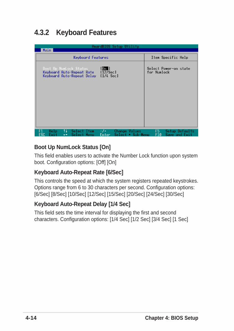
4-14 Chapter 4: BIOS Setup
4.3.2 Keyboard Features
Boot Up NumLock Status [On]This field enables users to activate the Number Lock function upon systemboot. Configuration options: [Off] [On]
Keyboard Auto-Repeat Rate [6/Sec]This controls the speed at which the system registers repeated keystrokes.Options range from 6 to 30 characters per second. Configuration options:[6/Sec] [8/Sec] [10/Sec] [12/Sec] [15/Sec] [20/Sec] [24/Sec] [30/Sec]
Keyboard Auto-Repeat Delay [1/4 Sec]This field sets the time interval for displaying the first and secondcharacters. Configuration options: [1/4 Sec] [1/2 Sec] [3/4 Sec] [1 Sec]
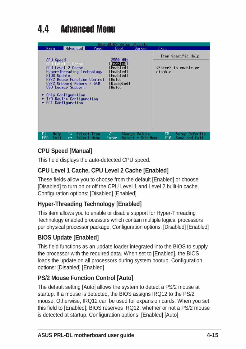
ASUS PRL-DL motherboard user guide 4-15
4.4 Advanced Menu
CPU Speed [Manual]This field displays the auto-detected CPU speed.
CPU Level 1 Cache, CPU Level 2 Cache [Enabled]These fields allow you to choose from the default [Enabled] or choose[Disabled] to turn on or off the CPU Level 1 and Level 2 built-in cache.Configuration options: [Disabled] [Enabled]
Hyper-Threading Technology [Enabled]This item allows you to enable or disable support for Hyper-ThreadingTechnology enabled processors which contain multiple logical processorsper physical processor package. Configuration options: [Disabled] [Enabled]
BIOS Update [Enabled]This field functions as an update loader integrated into the BIOS to supplythe processor with the required data. When set to [Enabled], the BIOSloads the update on all processors during system bootup. Configurationoptions: [Disabled] [Enabled]
PS/2 Mouse Function Control [Auto]The default setting [Auto] allows the system to detect a PS/2 mouse atstartup. If a mouse is detected, the BIOS assigns IRQ12 to the PS/2mouse. Otherwise, IRQ12 can be used for expansion cards. When you setthis field to [Enabled], BIOS reserves IRQ12, whether or not a PS/2 mouseis detected at startup. Configuration options: [Enabled] [Auto]
4-16 Chapter 4: BIOS Setup
OS/2 Onboard Memory > 64M [Disabled]When using OS/2 operating systems with installed DRAM of greater than64MB, you need to set this option to [Enabled]. Otherwise, leave to thedefault setting [Disabled]. Configuration options: [Disabled] [Enabled]
USB Legacy Support [Auto]This motherboard supports Universal Serial Bus (USB) devices. Thedefault of [Auto] allows the system to detect a USB device at startup. Ifdetected, the USB controller legacy mode is enabled. If not detected, theUSB controller legacy mode is disabled.
When you set this field to [Disabled], the USB controller legacy mode isdisabled whether or not you are using a USB device. Configurationoptions: [Disabled] [Enabled] [Auto]
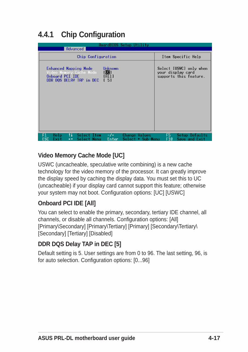
ASUS PRL-DL motherboard user guide 4-17
4.4.1 Chip Configuration
Video Memory Cache Mode [UC]USWC (uncacheable, speculative write combining) is a new cachetechnology for the video memory of the processor. It can greatly improvethe display speed by caching the display data. You must set this to UC(uncacheable) if your display card cannot support this feature; otherwiseyour system may not boot. Configuration options: [UC] [USWC]
Onboard PCI IDE [All]You can select to enable the primary, secondary, tertiary IDE channel, allchannels, or disable all channels. Configuration options: [All][Primary\Secondary] [Primary\Tertiary] [Primary] [Secondary\Tertiary\[Secondary] [Tertiary] [Disabled]
DDR DQS Delay TAP in DEC [5]Default setting is 5. User settings are from 0 to 96. The last setting, 96, isfor auto selection. Configuration options: [0...96]
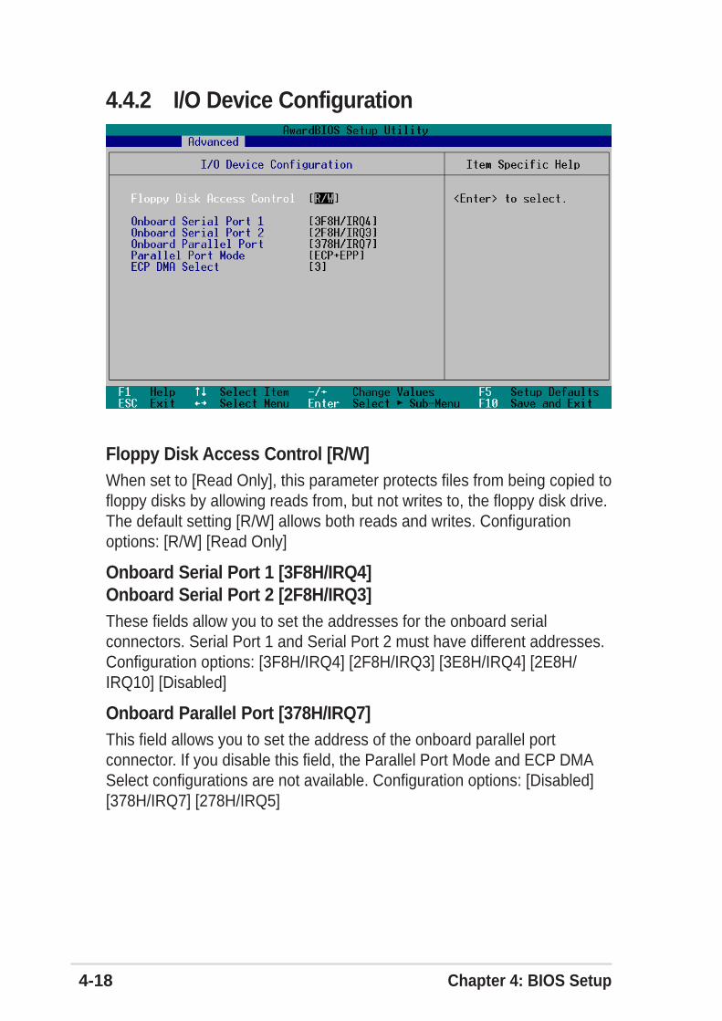
4-18 Chapter 4: BIOS Setup
4.4.2 I/O Device Configuration
Floppy Disk Access Control [R/W]When set to [Read Only], this parameter protects files from being copied tofloppy disks by allowing reads from, but not writes to, the floppy disk drive.The default setting [R/W] allows both reads and writes. Configurationoptions: [R/W] [Read Only]
Onboard Serial Port 1 [3F8H/IRQ4]Onboard Serial Port 2 [2F8H/IRQ3]These fields allow you to set the addresses for the onboard serialconnectors. Serial Port 1 and Serial Port 2 must have different addresses.Configuration options: [3F8H/IRQ4] [2F8H/IRQ3] [3E8H/IRQ4] [2E8H/IRQ10] [Disabled]
Onboard Parallel Port [378H/IRQ7]This field allows you to set the address of the onboard parallel portconnector. If you disable this field, the Parallel Port Mode and ECP DMASelect configurations are not available. Configuration options: [Disabled][378H/IRQ7] [278H/IRQ5]
ASUS PRL-DL motherboard user guide 4-19
Parallel Port Mode [ECP+EPP]This field allows you to set the operation mode of the parallel port.[Normal] allows normal-speed operation but in one direction only; [EPP]allows bidirectional parallel port operation; [ECP] allows the parallel port tooperate in bidirectional DMA mode; [ECP+EPP] allows normal speedoperation in a two-way mode. Configuration options: [Normal] [EPP] [ECP][ECP+EPP]
ECP DMA Select [3]This field allows you to configure the parallel port DMA channel for theselected ECP mode. This selection is available only if you select [ECP] or[ECP+EPP] in Parallel Port Mode above. Configuration options: [1] [3]
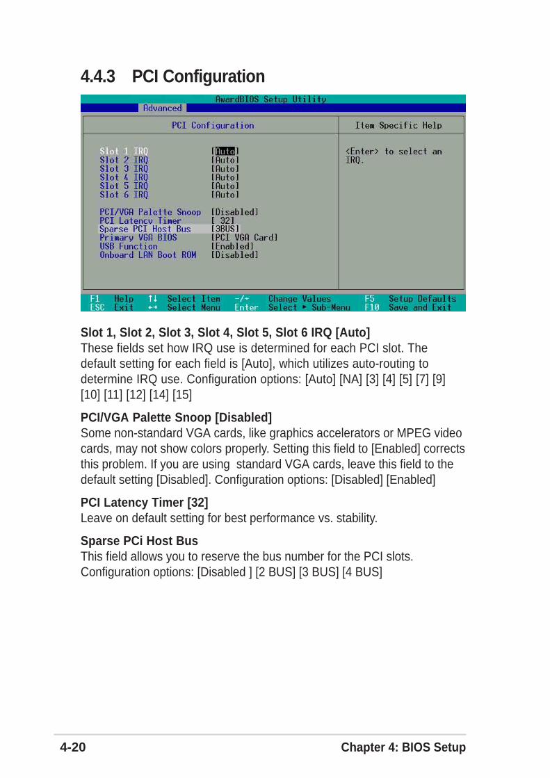
4-20 Chapter 4: BIOS Setup
4.4.3 PCI Configuration
Slot 1, Slot 2, Slot 3, Slot 4, Slot 5, Slot 6 IRQ [Auto]These fields set how IRQ use is determined for each PCI slot. Thedefault setting for each field is [Auto], which utilizes auto-routing todetermine IRQ use. Configuration options: [Auto] [NA] [3] [4] [5] [7] [9][10] [11] [12] [14] [15]
PCI/VGA Palette Snoop [Disabled]Some non-standard VGA cards, like graphics accelerators or MPEG videocards, may not show colors properly. Setting this field to [Enabled] correctsthis problem. If you are using standard VGA cards, leave this field to thedefault setting [Disabled]. Configuration options: [Disabled] [Enabled]
PCI Latency Timer [32]Leave on default setting for best performance vs. stability.
Sparse PCi Host BusThis field allows you to reserve the bus number for the PCI slots.Configuration options: [Disabled ] [2 BUS] [3 BUS] [4 BUS]
ASUS PRL-DL motherboard user guide 4-21
Primary VGA BIOS First [PCI VGA Card]This field allows you to select the primary graphics card. Configurationoptions: [PCI VGA Card] [Onboard VGA]
USB Function [Enabled]Set this field to [Enabled] if you want to use Universal Serial Bus devices.Configuration options: [Disabled] [Enabled]
Onboard LAN Boot ROM [Disabled]When set to [Enabled], these fields allow the system to boot from thenetwork using the onboard LAN controller boot ROM. Configurationoptions: [Disabled] [Enabled]
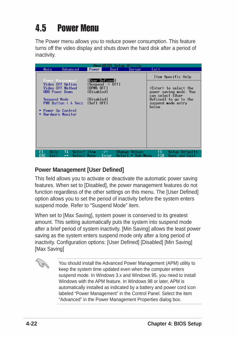
4-22 Chapter 4: BIOS Setup
4.5 Power MenuThe Power menu allows you to reduce power consumption. This featureturns off the video display and shuts down the hard disk after a period ofinactivity.
Power Management [User Defined]This field allows you to activate or deactivate the automatic power savingfeatures. When set to [Disabled], the power management features do notfunction regardless of the other settings on this menu. The [User Defined]option allows you to set the period of inactivity before the system enterssuspend mode. Refer to “Suspend Mode” item.
When set to [Max Saving], system power is conserved to its greatestamount. This setting automatically puts the system into suspend modeafter a brief period of system inactivity. [Min Saving] allows the least powersaving as the system enters suspend mode only after a long period ofinactivity. Configuration options: [User Defined] [Disabled] [Min Saving][Max Saving]
You should install the Advanced Power Management (APM) utility tokeep the system time updated even when the computer enterssuspend mode. In Windows 3.x and Windows 95, you need to installWindows with the APM feature. In Windows 98 or later, APM isautomatically installed as indicated by a battery and power cord iconlabeled “Power Management” in the Control Panel. Select the item“Advanced” in the Power Management Properties dialog box.
ASUS PRL-DL motherboard user guide 4-23
Video Off Option [Suspend -> Off ]This field determines when to activate the video off feature for monitorpower management. Configuration options: [Always On] [Suspend -> Off]
Video Off Method [DPMS OFF]This field defines the video off features. The Display Power ManagementSystem (DPMS) feature allows the BIOS to control the video display card ifit supports the DPMS feature. [Blank Screen] only blanks the screen. Usethis for monitors without power management or “green” features.
Even if installed, your screen saver does not display when you select[Blank Screen] for the above field.
[V/H SYNC+Blank] blanks the screen and turns off vertical and horizontalscanning. Configuration options: [Blank Screen] [V/H SYNC+Blank][DPMS Standby] [DPMS Suspend] [DPMS OFF] [DPMS Reduce ON]
HDD Power Down [Disabled]Shuts down any IDE hard disk drives in the system after a period ofinactivity as set in this user-configurable field. This feature does not affectSCSI hard drives. Configuration options: [Disabled] [1 Min] [2 Min] [3Min]...[15 Min]
Suspend Mode [Disabled]Sets the time period before the system goes into suspend mode.Configuration options: [Disabled] [1~2 Min] [2~3 Min] [4~5 min] [8~9 Min][20 Min] [30 Min] [40 Min] [1 Hour]
PWR Button < 4 Secs [Soft Off]When set to [Soft off], the ATX switch can be used as a normal systempower-off button when pressed for less than 4 seconds. [Suspend] allowsthe button to have a dual function where pressing less than 4 secondsputs the system in sleep mode. Regardless of the setting, holding the ATXswitch for more than 4 seconds powers off the system. Configurationoptions: [Soft off] [Suspend]
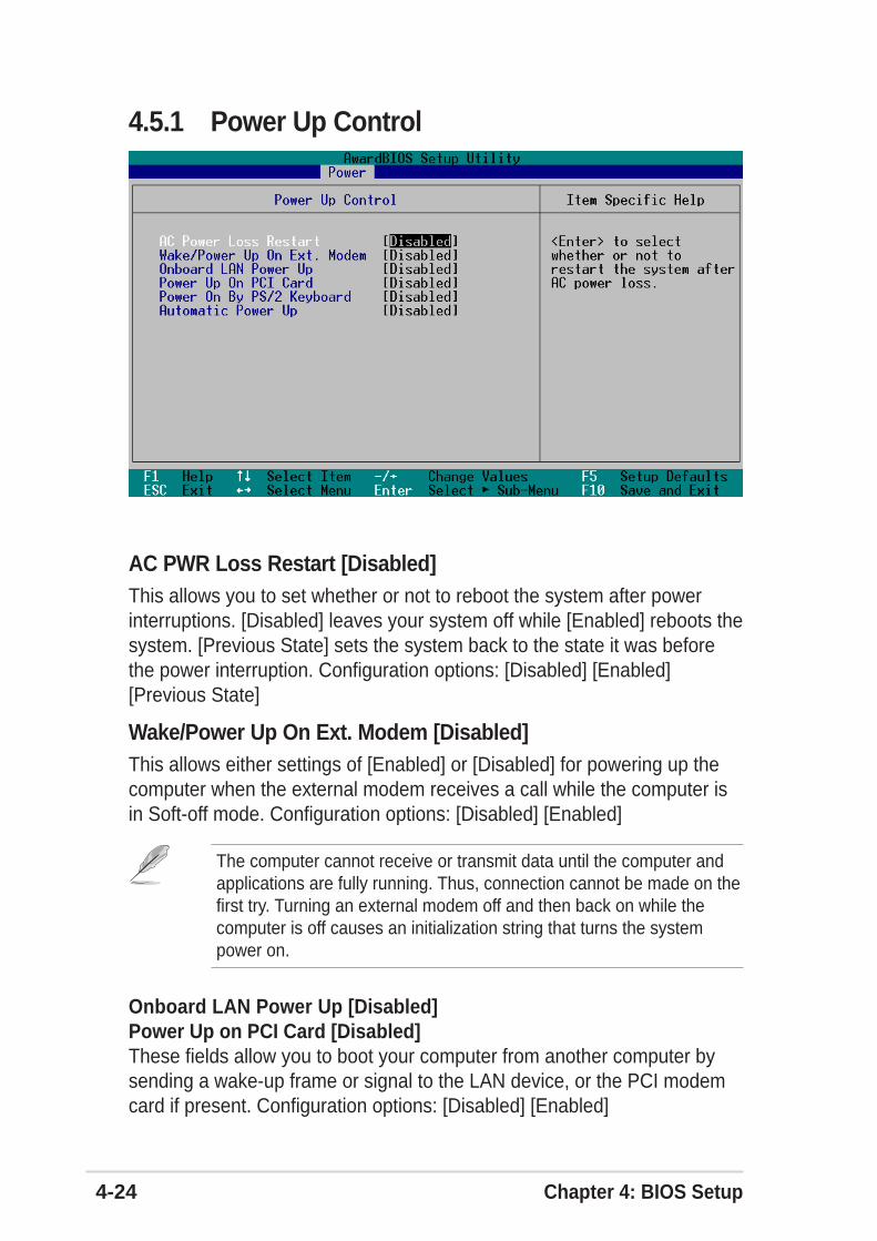
4-24 Chapter 4: BIOS Setup
4.5.1 Power Up Control
AC PWR Loss Restart [Disabled]This allows you to set whether or not to reboot the system after powerinterruptions. [Disabled] leaves your system off while [Enabled] reboots thesystem. [Previous State] sets the system back to the state it was beforethe power interruption. Configuration options: [Disabled] [Enabled][Previous State]
Wake/Power Up On Ext. Modem [Disabled]This allows either settings of [Enabled] or [Disabled] for powering up thecomputer when the external modem receives a call while the computer isin Soft-off mode. Configuration options: [Disabled] [Enabled]
The computer cannot receive or transmit data until the computer andapplications are fully running. Thus, connection cannot be made on thefirst try. Turning an external modem off and then back on while thecomputer is off causes an initialization string that turns the systempower on.
Onboard LAN Power Up [Disabled]Power Up on PCI Card [Disabled]These fields allow you to boot your computer from another computer bysending a wake-up frame or signal to the LAN device, or the PCI modemcard if present. Configuration options: [Disabled] [Enabled]
ASUS PRL-DL motherboard user guide 4-25
Power On By PS/2 Keyboard [Disabled]This parameter allows you to use specific keys on the keyboard to turn onthe system. This feature requires an ATX power supply that provides atleast 1A on the +5VSB lead. Configuration options: [Disabled] [Space Bar][Ctrl-Esc] [Power Key]
Automatic Power Up [Disabled]This allows an unattended or automatic system power up. You mayconfigure your system to power up at a certain time of the day by selecting[Everyday] or at a certain time and day by selecting [By Date].Configuration options: [Disabled] [Everyday] [By Date]
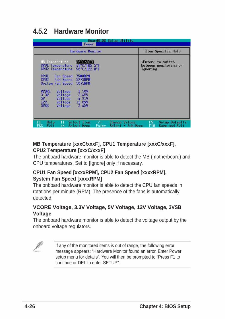
4-26 Chapter 4: BIOS Setup
4.5.2 Hardware Monitor
MB Temperature [xxxC/xxxF], CPU1 Temperature [xxxC/xxxF],CPU2 Temperature [xxxC/xxxF]The onboard hardware monitor is able to detect the MB (motherboard) andCPU temperatures. Set to [Ignore] only if necessary.
CPU1 Fan Speed [xxxxRPM], CPU2 Fan Speed [xxxxRPM],System Fan Speed [xxxxRPM]The onboard hardware monitor is able to detect the CPU fan speeds inrotations per minute (RPM). The presence of the fans is automaticallydetected.
VCORE Voltage, 3.3V Voltage, 5V Voltage, 12V Voltage, 3VSBVoltageThe onboard hardware monitor is able to detect the voltage output by theonboard voltage regulators.
If any of the monitored items is out of range, the following errormessage appears: “Hardware Monitor found an error. Enter Powersetup menu for details”. You will then be prompted to “Press F1 tocontinue or DEL to enter SETUP”.
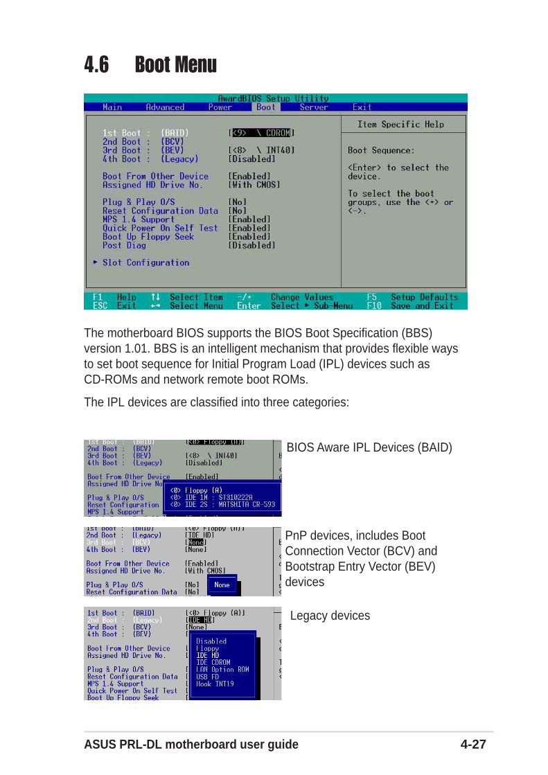
ASUS PRL-DL motherboard user guide 4-27
4.6 Boot Menu
BIOS Aware IPL Devices (BAID)
Legacy devices
The motherboard BIOS supports the BIOS Boot Specification (BBS)version 1.01. BBS is an intelligent mechanism that provides flexible waysto set boot sequence for Initial Program Load (IPL) devices such asCD-ROMs and network remote boot ROMs.
The IPL devices are classified into three categories:
PnP devices, includes BootConnection Vector (BCV) andBootstrap Entry Vector (BEV)devices
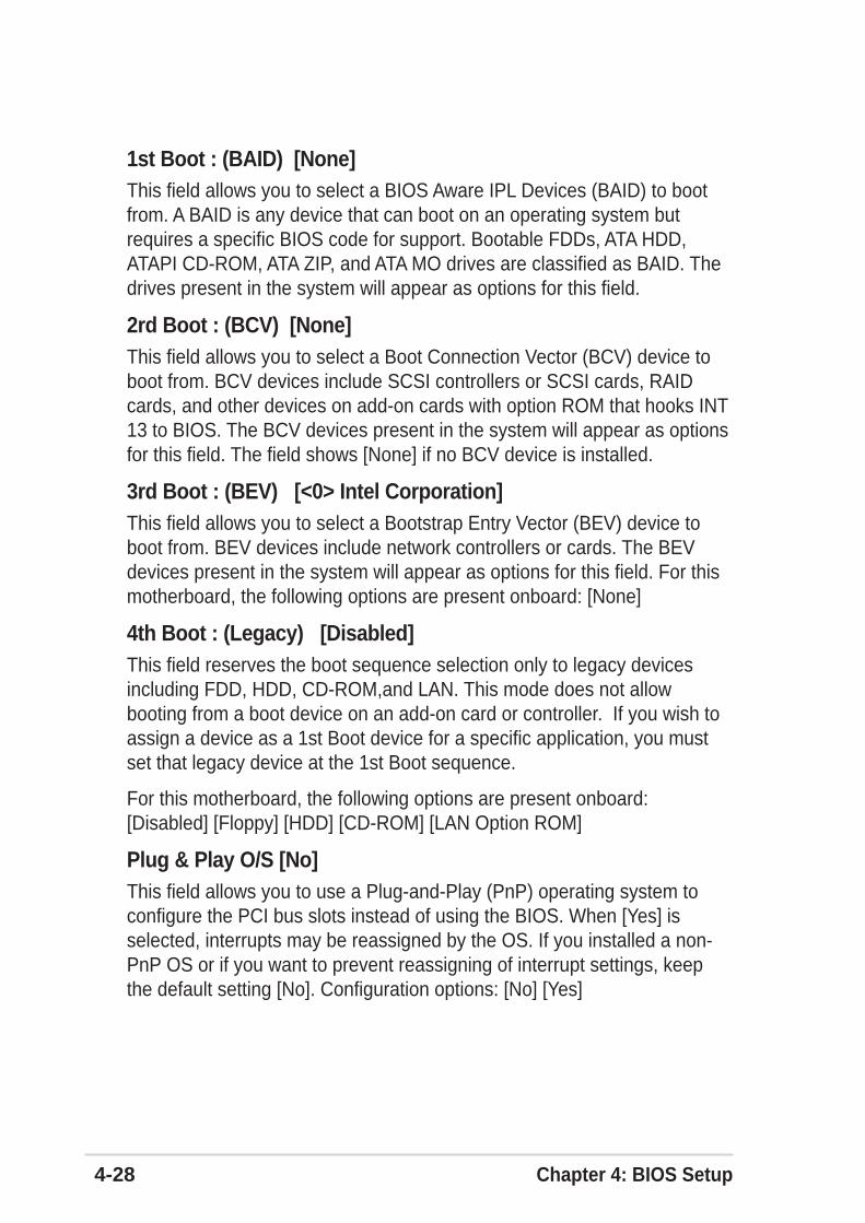
4-28 Chapter 4: BIOS Setup
1st Boot : (BAID) [None]This field allows you to select a BIOS Aware IPL Devices (BAID) to bootfrom. A BAID is any device that can boot on an operating system butrequires a specific BIOS code for support. Bootable FDDs, ATA HDD,ATAPI CD-ROM, ATA ZIP, and ATA MO drives are classified as BAID. Thedrives present in the system will appear as options for this field.
2rd Boot : (BCV) [None]This field allows you to select a Boot Connection Vector (BCV) device toboot from. BCV devices include SCSI controllers or SCSI cards, RAIDcards, and other devices on add-on cards with option ROM that hooks INT13 to BIOS. The BCV devices present in the system will appear as optionsfor this field. The field shows [None] if no BCV device is installed.
3rd Boot : (BEV) [<0> Intel Corporation]This field allows you to select a Bootstrap Entry Vector (BEV) device toboot from. BEV devices include network controllers or cards. The BEVdevices present in the system will appear as options for this field. For thismotherboard, the following options are present onboard: [None]
4th Boot : (Legacy) [Disabled]This field reserves the boot sequence selection only to legacy devicesincluding FDD, HDD, CD-ROM,and LAN. This mode does not allowbooting from a boot device on an add-on card or controller. If you wish toassign a device as a 1st Boot device for a specific application, you mustset that legacy device at the 1st Boot sequence.
For this motherboard, the following options are present onboard:[Disabled] [Floppy] [HDD] [CD-ROM] [LAN Option ROM]
Plug & Play O/S [No]This field allows you to use a Plug-and-Play (PnP) operating system toconfigure the PCI bus slots instead of using the BIOS. When [Yes] isselected, interrupts may be reassigned by the OS. If you installed a non-PnP OS or if you want to prevent reassigning of interrupt settings, keepthe default setting [No]. Configuration options: [No] [Yes]
ASUS PRL-DL motherboard user guide 4-29
Reset Configuration Data [No]The Extended System Configuration Data (ESCD) contain informationabout non-PnP devices. It also holds the complete record of how thesystem was configured the last time it was booted. Select [Yes] if you wantto clear these data during the Power-On-Self-Test (POST). Configurationoptions: [No] [Yes]
MPS 1.4 Support [Enabled]This field allows you to enable or disable the MultiProcessor Specification1.4 support. Configuration options: [Disabled] [Enabled]
Quick Power On Self Test [Enabled]This field speeds up the Power-On-Self Test (POST) routine by skippingretesting a second, third, and fourth time. Configuration options: [Disabled][Enabled]
Boot Up Floppy Seek [Enabled]When enabled, the BIOS will seek the floppy disk drive to determinewhether the drive has 40 or 80 tracks. Configuration options: [Disabled][Enabled]
Post Diag [Disabled]Configuration options: [Disabled] [Enabled]
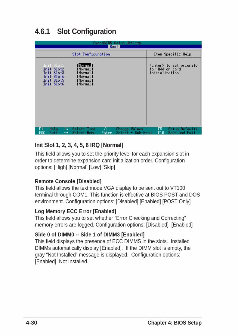
4-30 Chapter 4: BIOS Setup
Remote Console [Disabled]This field allows the text mode VGA display to be sent out to VT100terminal through COM1. This function is effective at BIOS POST and DOSenvironment. Configuration options: [Disabled] [Enabled] [POST Only]
Log Memory ECC Error [Enabled]This field allows you to set whether “Error Checking and Correcting”memory errors are logged. Configuration options: [Disabled] [Enabled]
Side 0 of DIMM0 -- Side 1 of DIMM3 [Enabled]This field displays the presence of ECC DIMMS in the slots. InstalledDIMMs automatically display [Enabled]. If the DIMM slot is empty, thegray “Not Installed” message is displayed. Configuration options:[Enabled] Not Installed.
4.6.1 Slot Configuration
Init Slot 1, 2, 3, 4, 5, 6 IRQ [Normal]This field allows you to set the priority level for each expansion slot inorder to determine expansion card initialization order. Configurationoptions: [High] [Normal] [Low] [Skip]
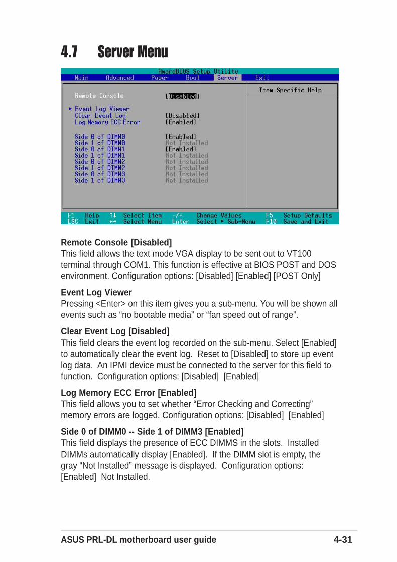
ASUS PRL-DL motherboard user guide 4-31
4.7 Server Menu
Remote Console [Disabled]This field allows the text mode VGA display to be sent out to VT100terminal through COM1. This function is effective at BIOS POST and DOSenvironment. Configuration options: [Disabled] [Enabled] [POST Only]
Event Log ViewerPressing <Enter> on this item gives you a sub-menu. You will be shown allevents such as “no bootable media” or “fan speed out of range”.
Clear Event Log [Disabled]This field clears the event log recorded on the sub-menu. Select [Enabled]to automatically clear the event log. Reset to [Disabled] to store up eventlog data. An IPMI device must be connected to the server for this field tofunction. Configuration options: [Disabled] [Enabled]
Log Memory ECC Error [Enabled]This field allows you to set whether “Error Checking and Correcting”memory errors are logged. Configuration options: [Disabled] [Enabled]
Side 0 of DIMM0 -- Side 1 of DIMM3 [Enabled]This field displays the presence of ECC DIMMS in the slots. InstalledDIMMs automatically display [Enabled]. If the DIMM slot is empty, thegray “Not Installed” message is displayed. Configuration options:[Enabled] Not Installed.
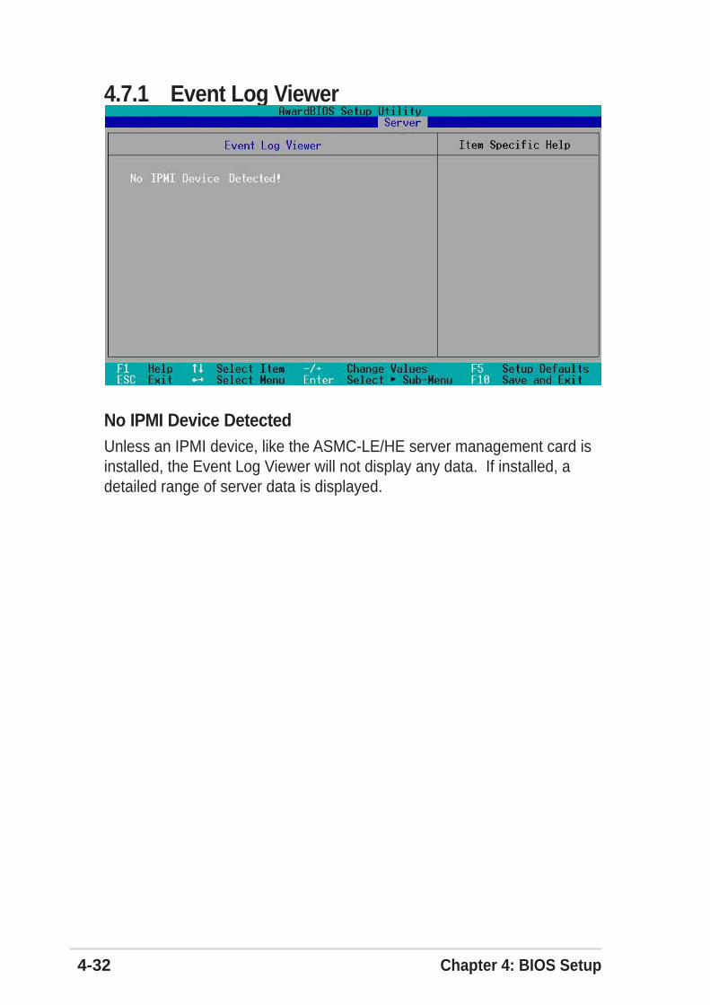
4-32 Chapter 4: BIOS Setup
No IPMI Device DetectedUnless an IPMI device, like the ASMC-LE/HE server management card isinstalled, the Event Log Viewer will not display any data. If installed, adetailed range of server data is displayed.
4.7.1 Event Log Viewer
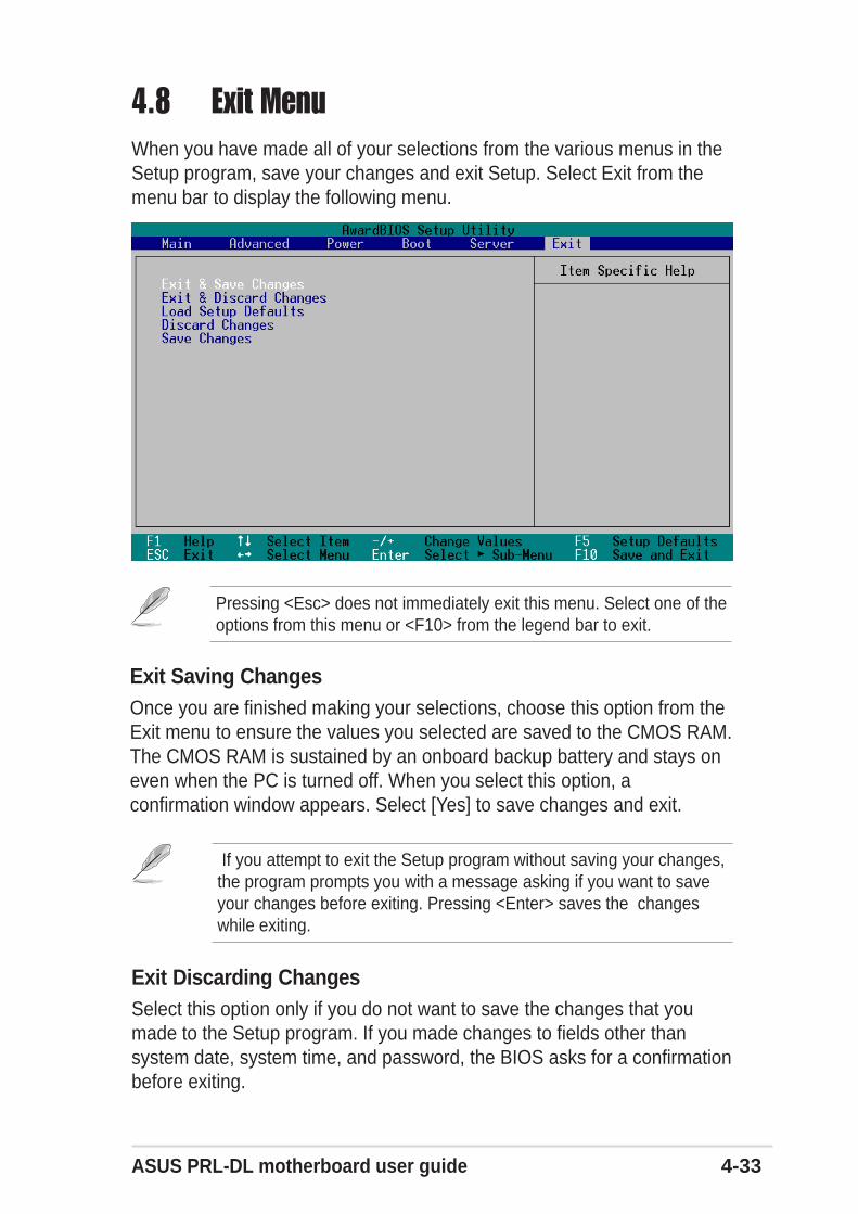
ASUS PRL-DL motherboard user guide 4-33
4.8 Exit MenuWhen you have made all of your selections from the various menus in theSetup program, save your changes and exit Setup. Select Exit from themenu bar to display the following menu.
Exit Saving ChangesOnce you are finished making your selections, choose this option from theExit menu to ensure the values you selected are saved to the CMOS RAM.The CMOS RAM is sustained by an onboard backup battery and stays oneven when the PC is turned off. When you select this option, aconfirmation window appears. Select [Yes] to save changes and exit.
Pressing <Esc> does not immediately exit this menu. Select one of theoptions from this menu or <F10> from the legend bar to exit.
If you attempt to exit the Setup program without saving your changes,the program prompts you with a message asking if you want to saveyour changes before exiting. Pressing <Enter> saves the changeswhile exiting.
Exit Discarding ChangesSelect this option only if you do not want to save the changes that youmade to the Setup program. If you made changes to fields other thansystem date, system time, and password, the BIOS asks for a confirmationbefore exiting.
4-34 Chapter 4: BIOS Setup
Load Setup DefaultsThis option allows you to load the default values for each of theparameters on the Setup menus. When you select this option or if youpress <F5>, a confirmation window appears. Select [Yes] to load defaultvalues. Select Exit Saving Changes or make other changes before savingthe values to the non-volatile RAM.
Discard ChangesThis option allows you to discard the selections you made and restore thepreviously saved values. After selecting this option, a confirmationappears. Select [Yes] to discard any changes and load the previouslysaved values.
Save ChangesThis option saves your selections without exiting the Setup program. Youcan then return to other menus and make further changes. After you selectthis option, a confirmation window appears. Select [Yes] to save anychanges to the non-volatile RAM.
Chapter 5
Support CD
This chapter gives information on theprovided motherboard support CD.
ASUS PRL-DL motherboard
Chapter summary
5.1 Microsoft Windows NT Server
5.2 Microsoft Windows 2000 Server
5.3 Microsoft Windows XP Professional
5.4 Novell NetWare Server
5.5 SCO Open Server 5.0.x
5.6 Linux RedHat 7.x
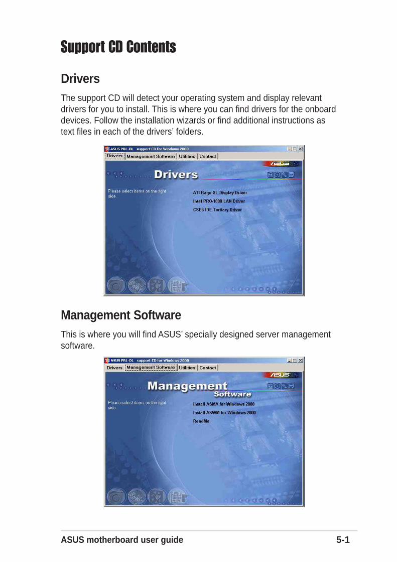
ASUS motherboard user guide 5-1
Support CD Contents
DriversThe support CD will detect your operating system and display relevantdrivers for you to install. This is where you can find drivers for the onboarddevices. Follow the installation wizards or find additional instructions astext files in each of the drivers’ folders.
Management SoftwareThis is where you will find ASUS’ specially designed server managementsoftware.
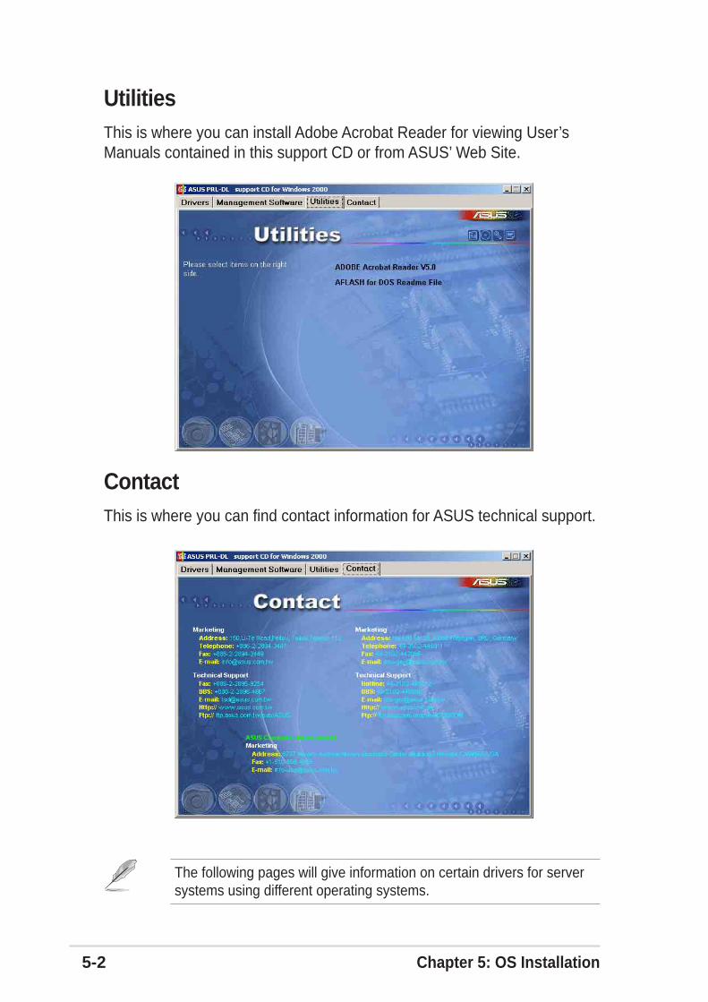
5-2 Chapter 5: OS Installation
ContactThis is where you can find contact information for ASUS technical support.
UtilitiesThis is where you can install Adobe Acrobat Reader for viewing User’sManuals contained in this support CD or from ASUS’ Web Site.
The following pages will give information on certain drivers for serversystems using different operating systems.
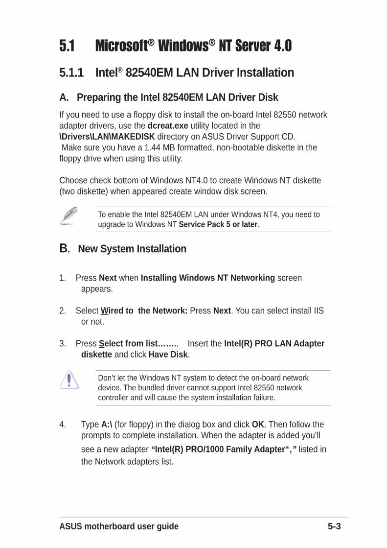
ASUS motherboard user guide 5-3
5.1.1 Intel® 82540EM LAN Driver Installation
A. Preparing the Intel 82540EM LAN Driver Disk
If you need to use a floppy disk to install the on-board Intel 82550 networkadapter drivers, use the dcreat.exe utility located in the\Drivers\LAN\MAKEDISK directory on ASUS Driver Support CD. Make sure you have a 1.44 MB formatted, non-bootable diskette in thefloppy drive when using this utility.
Choose check bottom of Windows NT4.0 to create Windows NT diskette(two diskette) when appeared create window disk screen.
To enable the Intel 82540EM LAN under Windows NT4, you need toupgrade to Windows NT Service Pack 5 or later.
5.1 Microsoft® Windows® NT Server 4.0
B. New System Installation
1. Press Next when Installing Windows NT Networking screenappears.
2. Select Wired to the Network: Press Next. You can select install IISor not.
3. Press Select from list…….. Insert the Intel(R) PRO LAN Adapterdiskette and click Have Disk.
Don’t let the Windows NT system to detect the on-board networkdevice. The bundled driver cannot support Intel 82550 networkcontroller and will cause the system installation failure.
4. Type A:\ (for floppy) in the dialog box and click OK. Then follow theprompts to complete installation. When the adapter is added you’ll
see a new adapter “Intel(R) PRO/1000 Family Adapter“,” listed inthe Network adapters list.
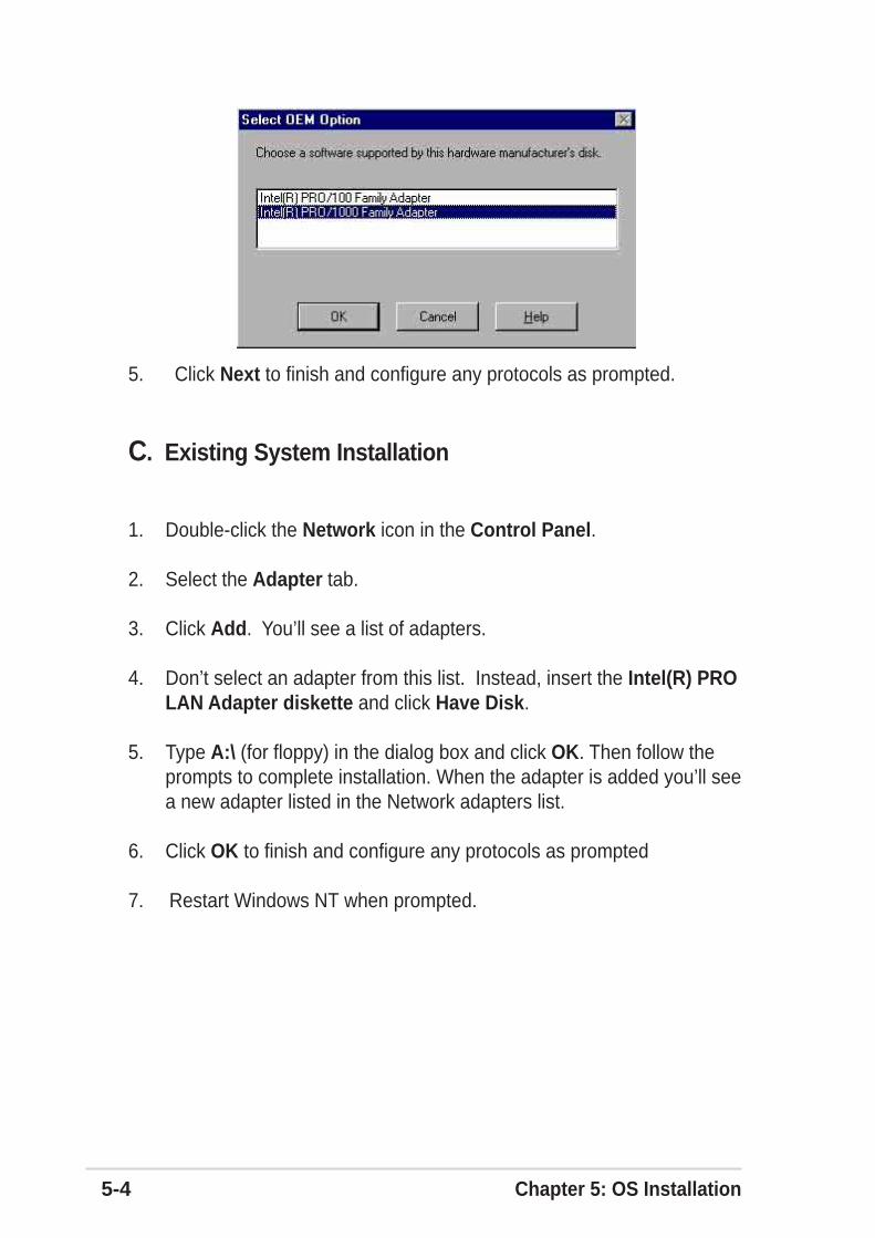
5-4 Chapter 5: OS Installation
5. Click Next to finish and configure any protocols as prompted.
C. Existing System Installation
1. Double-click the Network icon in the Control Panel.
2. Select the Adapter tab.
3. Click Add. You’ll see a list of adapters.
4. Don’t select an adapter from this list. Instead, insert the Intel(R) PROLAN Adapter diskette and click Have Disk.
5. Type A:\ (for floppy) in the dialog box and click OK. Then follow theprompts to complete installation. When the adapter is added you’ll seea new adapter listed in the Network adapters list.
6. Click OK to finish and configure any protocols as prompted
7. Restart Windows NT when prompted.
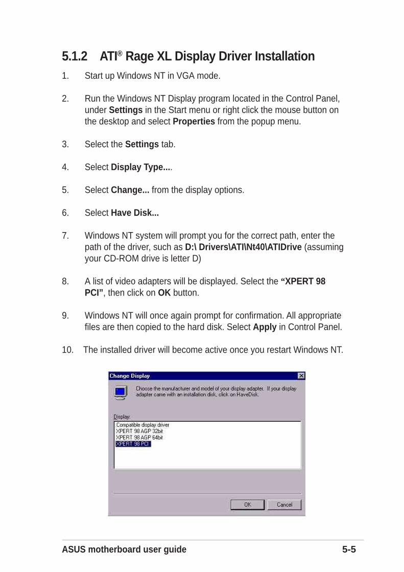
ASUS motherboard user guide 5-5
5.1.2 ATI® Rage XL Display Driver Installation1. Start up Windows NT in VGA mode.
2. Run the Windows NT Display program located in the Control Panel,under Settings in the Start menu or right click the mouse button onthe desktop and select Properties from the popup menu.
3. Select the Settings tab.
4. Select Display Type....
5. Select Change... from the display options.
6. Select Have Disk...
7. Windows NT system will prompt you for the correct path, enter thepath of the driver, such as D:\ Drivers\ATI\Nt40\ATIDrive (assumingyour CD-ROM drive is letter D)
8. A list of video adapters will be displayed. Select the “XPERT 98PCI”, then click on OK button.
9. Windows NT will once again prompt for confirmation. All appropriatefiles are then copied to the hard disk. Select Apply in Control Panel.
10. The installed driver will become active once you restart Windows NT.
5-6 Chapter 5: OS Installation
5.2.1 Intel® 82540EM LAN Driver InstallationYou may install the Intel LAN drivers directly from the support CD. Proceedto the section “B. Update LAN Driver on an Existing System Installation.”
If you wish to create a LAN driver disk, proceed to the section“A.Preparing the Intel LAN Driver Disk.”
A. Preparing the Intel 82540EM LAN Driver Disk
5.2 Microsoft® Windows® 2000 Server
If you need to use a floppy disk to install the on-board Intel 82540EMnetwork adapter drivers, use the dcreat.exe utility located inthe\Drivers\LAN\MAKEDISK directory on ASUS Driver Support CD. Make sure you have a 1.44 MB formatted, non-bootable diskette in thefloppy drive when using this utility.
Choose check bottom of Windows 2000 to create Windows 2000 diskette(one diskette) when appeared create window disk screen.
B. Update Driver on an Existing System Installation
1. Boot Windows 2000 system and log on as Administrator.
2. Click on the Start button. Select Settings—>Control Panel.
3. Double-click the System icon in the Control Panel. Select theHardware tab. Click on Device Manager…. Button.
4. Click the Other Devices. And highlight “Ethernet Controller”.Click right-button on the mouse. Select Properties.
5. Select the Driver tab. Click on Update Drivers.. Button.
6. Click Next. Select the “Display a list of the known drivers for thisdevice ………….”.
7. Select “Network adapters” in Hardware Type and Click Next.
Prepare one blank formatted high density floppy disk beforeproceeding.
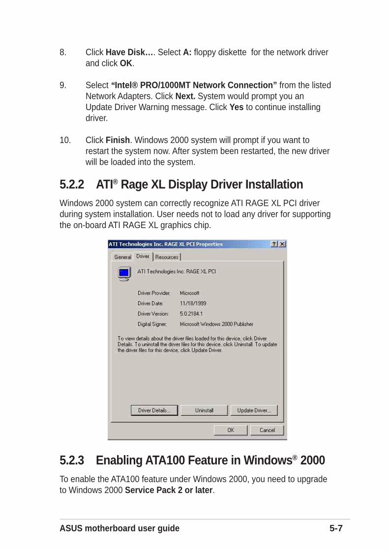
ASUS motherboard user guide 5-7
8. Click Have Disk…. Select A: floppy diskette for the network driverand click OK.
9. Select “Intel® PRO/1000MT Network Connection” from the listedNetwork Adapters. Click Next. System would prompt you anUpdate Driver Warning message. Click Yes to continue installingdriver.
10. Click Finish. Windows 2000 system will prompt if you want torestart the system now. After system been restarted, the new driverwill be loaded into the system.
5.2.2 ATI® Rage XL Display Driver InstallationWindows 2000 system can correctly recognize ATI RAGE XL PCI driverduring system installation. User needs not to load any driver for supportingthe on-board ATI RAGE XL graphics chip.
5.2.3 Enabling ATA100 Feature in Windows® 2000To enable the ATA100 feature under Windows 2000, you need to upgradeto Windows 2000 Service Pack 2 or later.
5-8 Chapter 5: OS Installation
5.3 Microsoft® Windows® XP Professional
5.3.1 Intel® 82540EM LAN Driver Installation
A. Preparing Intel 82540EM LAN Driver Disk
If you need to use a floppy disk to install the on-board Intel 82540EMnetwork adapter drivers, use the dcreat.exe utility located in the\Drivers\LAN\MAKEDISK directory on ASUS Driver Support CD. Make sure you have a 1.44 MB formatted, non-bootable diskette in thefloppy drive when using this utility.
Choose check bottom of Windows XP to create Windows XP diskette (onediskette) when appeared create window disk screen.
B. Update Driver on an Existing System Installation
1. Boot Windows XP system and log on as Administrator.
2. Click on the Start button. Select Settings—>Control Panel.
3. Double-click the System icon in the Control Panel. Select theHardware tab. Click on Device Manager…. Button.
4. Click the Other Devices. And highlight “Ethernet Controller”.Click right-button on the mouse. Select Properties.
5. Select the Driver tab. Click on Update Drivers.. Button.
6. Click Next. Select the “Install from a list or specificlocation[Advanced]”.
7. Click Next. Select A: floppy diskette for the network driver.
ASUS motherboard user guide 5-9
5.3.2 Enabling ATA100 Feature in Windows® XPProfessional
Windows XP system can correctly recognize ATI RAGE XL PCI driverduring system installation. User needs not to load any driver for supportingthe on-board ATI RAGE XL graphics chip.
8. Select “Intel® PRO/1000MT Network Connection” from the listedNetwork Adapters. Click Next. System would prompt you an UpdateDriver Warning message. Click Yes to continue installing driver.
9. Click Finish. Windows XP system will prompt if you want to restart the system now. After system been restarted, the new driver will be loaded into the system.
5-10 Chapter 5: OS Installation
B. NetWare 4.XX, 5.X, and 6.X Installations
1. Prepare the Intel(R) PRO LAN Adapter diskette from previoussection.
2. Install NetWare 4.xx or 5.x according to the NetWare instructions.
5.4.1 Intel® 82540EM LAN Driver Installation
A. Preparing Intel 82540EM LAN Driver Disk
1. Use the self-extracting image files:
For the Intel(R) PRO/1000 Server Adapter driver, the executable file islocated here:
\Drivers\Lan\makedisk\makenw.bat
2. Use the manual to create driver diskette:
If you need to use a floppy disk to install the on-board Intel 82550 networkadapter drivers, use the MAKEDISK.BAT utility located in the\Drivers\LAN\MAKEDISK directory on ASUS Driver Support CD.
MAKEDISK [operating system] [destination]
where [operating system] is the OS for which you are creating thediskette, and [destination] is the drive letter and path (such as A:). If nodestination is specified, the A: drive will be used. The possible [operatingsystem] options are:
NT = Microsoft Windows NTW2K = Microsoft Windows* 2000NW = Novell NetWare servers and clients
Make sure you have a 1.44 MB formatted, non-bootable diskette in thefloppy drive when using this utility.
5.4 Novell® NetWare® Server
ASUS motherboard user guide 5-11
If the “Loader could not find public symbol: <symbol name>” errormessage prompted when system is loading Intel PRO LAN adapterdriver, it is because the related network driver modules are too old.Download the latest Netware Support Pack from Novell web site at:http://support.novell.com/products/nw411/patches.htm
5.4.2 ATI® Rage XL Display Driver InstallationYou can select the “Super VGA” for the X Server on NetWare 5.x serversystem. The other NetWare system didn’t support X Server and you didn’tneed the VGA driver support.
3. When the NetWare installation procedure prompts you for a NetworkDriver, insert the Intel PRO/1000 driver diskette into drive A: Thenuse the INS key to select an unlisted driver. A dialog box appears.The “CE1000.LAN — Intel 8254X Based Network Connection“driver appear as a selection.
4. Installation of the Intel 82540EM Network Adapter for NetWare 5.x or4.xx is complete.
Add or check the load and bind statements you need to the server’sAUTOEXEC.NCF file so the
Intel(R) PRO LAN Adapter driver loads automatically load and bindthe server driver as follows:
LOAD CE1000 LAN SLOT=10004 FRAME=ETHERNET_IINAME=CE1000_1_EII
BIND IP CE1000_1_EII addr=xxx.xxx.xxx.xxxmask=xxx.xxx.xxx.xxx gate=xxx.xxx.xxx.xxx
5-12 Chapter 5: OS Installation
5.5.1 Intel® 82540EM LAN Driver InstallationSCO OpenServer 5.0.6 system can correctly recognize Intel network controllerduring installation. User doesn’t need to load or modify the network driver for theonboard LAN device.
You can find the Intel 82540 Network driver from support CD at:
\Drivers\Lan\UNIX\SCO5
Instructions for Installing the eeE Driver for SCO OpenServer
1. Copy the eee.vol file to any directory, say /tmp, on the SCO system,renaming the file as VOL.000.000. Also, make the file read-only by using‘chmod’.For example,
# cp eeE.vol /tmp/VOL.000.000# chmod 444 /tmp/VOL.000.000
2. If there is an older version of the eeE driver on the system, you must firstremove it. To do this, run ‘netconfig’. Remove all instances of the “Intel ...”adapters. Exit netconfig without opting to relink the kernel.
3. Install the new driver using ‘custom’. When asked for the installationmedia, choose ‘media images’, and type the directory path to theVOL.000.000 file. (In step 1, if you copied it to /tmp, type ‘/tmp’). After theinstallation of the driver is complete, exit ‘custom’.
4. Run ‘netconfig’ and add the adapters. For each adapter that is present inthe system, enter the appropriate TCP/IP parameters. By default, thedriver automatically detects the line speed and duplex mode. If you want toforce any of these settings, choose ‘Advanced Options’ and set the speedand duplex modes. Exit ‘netconfig’ and choose to relink the kernel.
5. Reboot the system. At the command prompt, type:
# reboot (or init 6)
5.5 SCO Open Server 5.0.x
5.5.2 ATI® Rage XL Display Driver InstallationSCO OpenServer 5.0.6 system can correctly recognize ATI Rage XLgraphic controller (ATI MACH64) during installation. User doesn’t need toload or modify the video driver for the onboard VGA device.
ASUS motherboard user guide 5-13
5.6 Linux RedHat 7.x
5.6.1 Intel 82540EM LAN Driver InstallationThis file describes the Linux* Base Driver for the Intel® PRO/1000 Familyof Adapters, version 4.1.x. This driver is intended for 2.2.x and 2.4.xkernels; it is known to build properly on 2.2.x kernels through 2.2.20 andon 2.4.x kernels through 2.4.17. Intel focused testing on Intel processor-based systems running kernels 2.4.7 and 2.2.16. This driver includessupport for Itanium™-based systems.The Intel PRO/1000 driver is only supported as a loadable module at thistime. Intel is not supplying patches against the kernel sourceto allow forstatic linking of the driver. For questions related to hardware requirements,refer to the documentation supplied with your Intel PRO/1000 adapter. Allhardware requirements listed apply to use with Linux.New features include support for the Intel® PRO/1000 MT DesktopAdapter.
Update Driver on an Existing System Installation
To build a binary RPM* package of this driver, run’rpm -tb<filename.tar.gz>’. Replace <filename.tar.gz> with thespecific file name ofthe driver.
For the build to work properly, the currently running kernel MUSTmatch the version and configuration of the installed kernel sources. Ifyou have just recompiled the kernel reboot the system now.
1. Move the base driver tar file to the directory of your choice. Forexample, use ‘/home/username/e1000’ or ‘/usr/local/src/e1000’.
2. Untar/unzip the archive, where x.x.x is the version number for thedriver tar:
tar zxf e1000-x.x.x.tar.gz
3. Change to the driver src directory, where x.x.x is the versionnumber for the driver tar:
cd e1000-x.x.x/src/
5-14 Chapter 5: OS Installation
5.6.2 ATI Rage XL Display Driver InstallationThe RedHat 7.x system can automatically recognize ATI Rage XL graphiccontroller (ATI MACH64) during installation. You don’t need to load ormodify the video driver for the onboard VGA device.
4. Compile the driver module:
make install
The binary will be installed as:
For Linux 2.2.x systems: /lib/modules/[KERNEL_VERSION]/net/e1000.o
For Linux 2.4.x systems:/lib/modules [KERNEL_VERSION]/kernel/drivers/net e1000.o
The install locations listed above are the default locations. They maynot be correct for certain Linux distributions. For more information, goto ldistrib.htm.
5. Install the module:
insmod e1000 <parameter>=<value>
6. Assign an IP address to the interface by entering the following,where x is the interface number:
ifconfig ethx <IP_address>
7. Verify that the interface works. Enter the following, where<IP_address> is the IP address for another machine on thesame subnet as the interface that is being tested:
ping <IP_address>