Embed Size (px)
Citation preview

P H Y S I C A L R E V I E W L E T T E R S week ending5 SEPTEMBER 2003VOLUME 91, NUMBER 10
Anatomy of a BathtubVortex
A. Andersen,1,2,* T. Bohr,1 B. Stenum,2 J. Juul Rasmussen,2 and B. Lautrup3
1The Technical University of Denmark, Department of Physics, DK-2800 Kgs. Lyngby, Denmark2Risø National Laboratory, Optics and Fluid Dynamics Department, DK-4000 Roskilde, Denmark
3The Niels Bohr Institute, Blegdamsvej 17, DK-2100 Copenhagen Ø, Denmark(Received 11 March 2003; published 5 September 2003)
104502-1
We present experiments and theory for the ‘‘bathtub vortex,’’ which forms when a fluid drains out ofa rotating cylindrical container through a small drain hole. The fast down-flow is found to be confinedto a narrow and rapidly rotating ‘‘drainpipe’’ from the free surface down to the drain hole. Surroundingthis drainpipe is a region with slow upward flow generated by the Ekman layer at the bottom of thecontainer. This flow structure leads us to a theoretical model similar to one obtained earlier byLundgren [J. Fluid Mech. 155, 381 (1985)], but here including surface tension and Ekman upwelling,comparing favorably with our measurements. At the tip of the needlelike surface depression, weobserve a bubble-forming instability at high rotation rates.
DOI: 10.1103/PhysRevLett.91.104502 PACS numbers: 47.32.–y, 47.45.Gx
FIG. 1. The bathtub vortex in a cylindrical container with adrain hole at the center of the bottom (not shown). The fluid inthe central region is rotating rapidly, and the depth of thefree surface dip depends on the rotation rate of the container.Picture (a) was taken at 6 rpm, (b) at 12 rpm, and (c) at 18 rpm.The drain hole radius was 0.1 cm and the unperturbed fluiddepth 10.9 cm. The rates of the out-flow were (a) 3:62 cm3 s�1,(b) 3:54 cm3 s�1, and (c) 3:16 cm3 s�1. The photographs weretaken through the square reservoir tank surrounding the cy-lindrical tank, and in each photograph the area is4:0 cm �horizontally� � 7:2 cm �vertically� and the lower edgeof the frame is 4.2 cm above the drain hole. The structure abovethe surface is due to reflections. The water is recirculatedthrough a rotationally symmetric inlet at the bottom of the
fix the size of the drain hole (and thus approximately the outer cylindrical boundary.
The generation of strongly localized vorticity is a fas-cinating and complicating ingredient of a broad variety offluid flows ranging from vortex shedding at solid surfaces(such as paddles, sand ripples, or insect wings) over flowsthrough turbines to large-scale tornadoes [1]. In general,these flows are poorly understood, since the interplaybetween fast axial motion and intense, localized vorticityleads to difficult mathematical problems outside the com-fortable realm of classical subjects such as potential flowor standard boundary layer theory.
One of the most well-known examples of such flows isthe so-called ‘‘bathtub vortex,’’ which forms when waterdrains out of a container. The strong, localized deforma-tion of the free surface makes the vortex beautifullyvisible, and has made the bathtub vortex the prototype‘‘vortex.’’ This popularity is in stark contrast to theattention which the phenomenon receives in the literature.The few classic papers about it either neglect the axialflow [2] or consider the problem without a free surface [3].Similarly, textbooks very seldom mention the bathtubvortex, and if they do [4,5] the flow is modeled withinpotential theory (with the inclusion of an ad hoc viscouscore [4]) without incorporating the axial motion. In thevortex core the axial velocity can be high, an essentialingredient of the strong ‘‘swirl’’ [6] which makes the flowso fascinating. Our aim in this Letter is to provide basicunderstanding of the stationary bathtub vortex: the flowstructure, the shape of the free surface, and the interde-pendence of important characteristics such as the size ofthe central surface depression, the rate of the out-flow,and the rotation rate in the vortex core.
We study a stationary bathtub vortex in a rotatingcontainer with a small drain hole at the bottom. Thecontainer is filled to a constant level with water, and theout-flow is driven by gravity. The free surface shapedepends strongly on the rate of the out-flow and less onthe rotation rate of the container. In the experiment, we
0031-9007=03=91(10)=104502(4)$20.00
flow rate) and vary the rotation rate (angular velocity) �.Pictures of the observed free surface profiles are shown inFig. 1. The surface depression increases with �, and at18 rpm the surface dip has a narrow, needlelike shape andis rotating very rapidly (around 104 rpm). At higher val-ues of the rotation rate, the tip is no longer stable: Airbubbles detach from it and are dragged down by thesurrounding flow as shown in Fig. 2. When � is increasedfurther, the frequency of bubble shedding increases untilthe air-filled core extends all the way down through thedrain hole.
2003 The American Physical Society 104502-1

FIG. 2. The tip of the surface depression is unstable when therotation rate of the container is high. An air bubble has justdetached from the tip and is dragged down the drain by thesurrounding flow.
FIG. 3 (color). (a) An overlay of two flow visualizations madeby adding fluorescent dye at the surface (red) and at the bottominlet (green), respectively. The red dye is flowing in a thinsurface layer to the central vortex core where it is diverteddownwards to the drain hole. The free surface dip is seen abovethe central red region (the red pattern above the surface is dueto reflections). The green dye spirals inward in the thin Ekmanlayer at the bottom, then upwards around the central drainpipe,and finally down the drain. Only a thin vertical cross sectionthrough the axis of symmetry is illuminated and thereby thespiraling upward motion gives rise to the layered structure ofthe green dye. (b) Sketch of the flow structure (not to scale).
P H Y S I C A L R E V I E W L E T T E R S week ending5 SEPTEMBER 2003VOLUME 91, NUMBER 10
The flow structure is surprisingly complex. Figure 3(a)shows an overlay of two flow visualizations made byadding fluorescent dye at the surface (red) and at thebottom inlet (green), respectively. The control parameterscorrespond to Fig. 1(b). The central down-flow region(red) below the free surface dip is strongly localized,and the downward velocities are of the order of 1 m s�1.This region appears similar to a weakly conical drainpipewith a radius comparable to that of the drain hole. Ifthis corresponds to the ‘‘esophagus’’ of the vortex, the‘‘mouth’’ would appear to be the surface region above thedrain, but in the stationary flow only a small fraction ofthe flow rate through the drain hole actually comes fromthis region. Nearly all of the flow rate is provided by thethin Ekman layer at the bottom of the container. In thisboundary layer, the fluid spirals inward. Close to the drainhole, a large part of it is diverted upward and the rest goesdirectly down the drain. We note that a similar up-flowwas observed by Lewellen [3] close to the drain hole in arotating flow without a free surface. Figure 3(b) summa-rizes the flow structure of the bathtub vortex: The flow1 cm away from the axis is upward (with velocities of theorder of 1 cm s�1), and most of the fluid passing outthrough the drain hole has thus taken a contorted pathin through the bottom Ekman layer, up through the next-to-central upwelling region, and finally down through therapidly rotating ‘‘porous’’ central drainpipe.
In the bulk of the container the flow is essentially twodimensional and well described as a central line vortexsuperimposed on the rigid rotation of the container.This means that the radial velocity u and the verticalvelocity w both vanish, whereas the azimuthal velocity
104502-2
v � vB�r� � � r� �=r, where � is the line vortexstrength. Large deviations from this are observed onlynear the boundaries and in the central region. Because ofthe mismatch between the rigidly rotating bottom and the�=r term in vB, an Ekman boundary layer is formed, withthe thickness � �
����������=�
p� 1 mm, where is the kine-
matic viscosity. By standard linear theory [7], one finds,
104502-2
P H Y S I C A L R E V I E W L E T T E R S week ending5 SEPTEMBER 2003VOLUME 91, NUMBER 10
in the reference frame rotating with rotation rate �,that ~uu�r; z� � ���=r� exp��z=�� sin�z=�� and ~vv�r; z� ���=r� �1� exp��z=�� cos�z=��. If we assume that themain flow rate F through the drain hole is carried bythe Ekman layer, we get F � �
R10 2 r~uu dz � ��, and
we can thus express the strength of the line vortex interms of the flow rate and the rotation rate as � �F
�����������=
p= . This result has been confirmed experimen-
tally for a source-sink flow without a free surface [8], andour particle tracking measurements at 6, 12, and 18 rpmagree with the prediction to within 10% [9]. The up-flowis similar to Ekman pumping, which in the linear ap-proximation [7] is proportional to the vertical componentof the vorticity, and it vanishes in the bulk since the bulkflow �=r is irrotational. At the smallest radii ~vv is linear inr, corresponding to the approximately rigid rotation ofthe core. A corresponding up-flow appears due to Ekmanpumping, but in this region the nonlinear terms becomeimportant and invalidate the linear Ekman theory. In anonlinear theory [10,11] of the Ekman layer, it is pre-dicted that the boundary layer thickness decreases towardthe center and that the up-flow in a vortex core in rigidrotation is reduced due to the nonlinear corrections.
The vertical down-flow in the central core is surpris-ingly localized. We have thus modeled the flow below thesurface dip as a ‘‘drainpipe,’’ i.e., as if it was limited by aboundary r0�z� on which w vanishes while u, v, and p arematched to the z-independent exterior bulk flow. In thevortex core u � w and v � w, and in this region thederivatives with respect to z in the viscous terms can beneglected in a boundary layer approximation of theNavier-Stokes equations. Within the drainpipe, we as-sumed a parabolic down-flow profile, and we expandedthe velocity components and the pressure in powers of r.We did not make any assumptions about the functionaldependence on z, and to lowest order in r the problemreduced to a closed set of differential equations for threefunctions of z. The details are reported elsewhere [9], butthe main property used in the following is that the highazimuthal velocity in the vortex core together with thematching to a z-independent exterior flow is sufficient toforce the flow in the vortex core to have a simple func-tional dependence where w is approximately linear in zinside the drainpipe, while r0 and the central rotationrate, �C, are approximately independent of z.
That u and v are approximately independent of zwhereas w is linear in z was used by Lundgren [12] toderive a set of differential equations for the free surfaceh�r�. With scales W for the vertical velocity in the vortexcore and H for the surface height, Lundgren showed thatthe velocity field has this functional form if the Rossbynumber Ro � W=�H�� � 1 and if W2 � 2gH, where gis the gravitational acceleration. These assumptions arevalid only for low flow rates and mild depressions of thefree surface. In our experiment Ro � 10, but we have asmall local Rossby number RoC � W=�H�C� � 10�2,defined in terms of the central rotation rate, and this is
104502-3
the relevant number if we restrict our attention to thecentral drainpipe. Since the out-flow is driven by gravity,our vertical velocities are of the order of the free fallvelocity W �
����������2gH
p� 1 m s�1, and we would thus ex-
pect significant corrections to Lundgren’s equationswhich assume hydrostatic pressure. However, as we shallsee below, Lundgren’s equations lead to surprisingly ac-curate predictions. The reason is probably that the char-acteristic vertical velocities near the free surface areconsiderably smaller than the free fall velocity at thedrain hole, due to the velocity increase down the drain-pipe and the stagnation point at the tip of the surfacedepression.
In the following, we apply Lundgren’s model [seeRef. [12] equations (4.1), (4.15), and (4.18)] and extendit to include surface tension. Knowledge of the verticalvelocity immediately above the Ekman layer w�z � 0�makes it possible to compute the product hu, since thekinematic boundary condition at the free surface and theincompressibility of the fluid lead to the equation
1
r
d�rhu�dr
� w�z � 0�: (1)
Inside the down-flow region, we assume a downward plugflow, and in the up-flow region our measurements show anexponential profile:
w�z � 0� �
(� Q
R2 if r � RQe��r�R�=d
2 d�R�d� if r > R;(2)
where the flow rate Q for the Ekman upwelling and thelength scales R and d are determined experimentally. Theflow rate Q is about 50% of the total flow rate, F, sincesome of the fluid carried by the Ekman layer flowsdirectly down the drain hole. The radius of the down-flow region above the drain hole decreases close to theoutlet due to the direct outflow from the Ekman layerthrough the drain hole. The effective value of R is there-fore slightly larger than the radius of the drain hole. Theradial and the axial Navier-Stokes equations lead with theassumptions RoC � 1 and W2 � 2gH to
v2
r� g
dhdr
���d�dr
; (3)
where � is the surface tension of the air-water interface, �is the density of water, and � � h0=fr�1� �h0�21=2g �h00=�1� �h0�23=2 is the curvature of the free surface.Compared to Lundgren’s original equations, we here in-troduce the surface tension correction to the pressuresince it is important in a quantitative comparison withour measurements. Finally, the azimuthal Navier-Stokesequation reduces to the equation
u�dvdr
�vr
��
�d2v
dr2�
1
rdvdr
�v
r2
�: (4)
The problem is thus reduced to solving Eqs. (3) and (4) forh and v using Eq. (1) and the bottom vertical velocityprofile in Eq. (2) to eliminate u.
104502-3

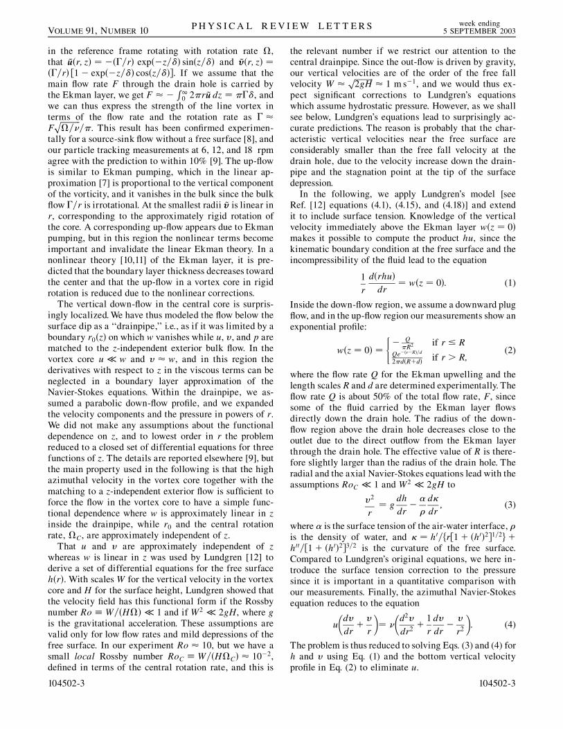
0
10
20
30
40
50
0 0.4 0.8 1.2 1.6 2
v [c
m/s
]
r [cm]
(b)
8
8.5
9
9.5
10
10.5
11
0 0.2 0.4 0.6 0.8 1
h [c
m]
r [cm]
(a)
FIG. 4 (color). Numerical solution of Lundgren’s equationswith surface tension (blue) and without surface tension (green)compared with experimental results (red) at 12 rpm. (a) Thefree surface and (b) the azimuthal velocity in the corotatingreference frame. We used g � 981 cm s�2, � � 1:0 g cm�3, � 0:0089 cm2 s�1, � � 65 g s�2, and d � 0:35 cm. To ob-tain the best possible agreement with the measurements, we setR � 0:16 cm and Q � 1:79 cm3 s�1 in the solution with sur-face tension, and R � 0:17 cm and Q � 1:76 cm3 s�1 in thesolution without surface tension. We measured � in the experi-ment, and the values of R, d, and Q are based on the best fit toour measured vertical velocities 1 cm above the bottom.
P H Y S I C A L R E V I E W L E T T E R S week ending5 SEPTEMBER 2003VOLUME 91, NUMBER 10
Figure 4 shows a comparison of the measured surfaceprofile and azimuthal velocities at 12 rpm [see Figs. 1(b)and 3(a)] and the corresponding numerical solution ofLundgren’s equations with and without surface tension.The numerical solution with surface tension agrees wellwith the measurements, whereas the model without sur-face tension overestimates the depth of the central surfacedepression by 70%. Difficulties in obtaining reliable ex-perimental data for the velocity field and numerical in-stabilities encountered with Eqs. (3) and (4) at highrotation rates have kept us from making a similar com-parison at 18 rpm.
The bubble-forming instability (Fig. 2) is induced bysurface tension. The capillary instability of a fluid col-
104502-4
umn [13] does not change qualitatively when it is rotating[14]. We therefore speculate that the critical value of �where the instability sets in occurs when the downwarddrag becomes large enough to overcome the upward buoy-ancy force and drag the bubbles formed by the capillaryinstability along with the flow. Using values for the dragon a spherical bubble at high Reynolds number [15], weestimate the critical value of the vertical velocity asWC � ga2=�9�, where a is the radius of the bubble.With a bubble radius of a � 0:5 mm, we find WC �25 cm s�1, which is in the measured range of w. We donot, however, have measurements of w immediately be-low the surface tip for � around 22 rpm when the tipbecomes unstable, and a precise test of the criterion forthe tip instability remains to be carried out.
We thank Jens Eggers and Vachtang Putkaradze fordrawing our attention to Ref. [12] and Tom Lundgrenfor helpful suggestions. We are thankful to MortenErnebjerg for help with measurements of the free surfacedepression, and to Mark Schram Christensen, MortenNørgaard Nielsen, and Jacob Richter for inspirationthrough a series of preparatory experiments. We acknowl-edge support from the Danish Natural Science ResearchCouncil Grant No. 24-56880.
*Present address: Cornell University, Dept. of Theoreticaland Applied Mech., Ithaca, NY 14853, USA.
[1] H. J. Lugt, Vortex Flow in Nature and Technology(Krieger, Malabar, Florida, 1995).
[2] H. A. Einstein and H. Li, in Proceedings of the HeatTransfer and Fluid Mechanics Institute, StanfordUniversity, 1951, p. 33.
[3] W. S. Lewellen, J. Fluid Mech. 14, 420 (1962).[4] H. Lamb, Hydrodynamics (Cambridge University Press,
Cambridge, U.K., 1932).[5] R. P. Feynman, R. B. Leighton, and M. Sands, The
Feynman Lectures on Physics (Addison-Wesley,Reading, 1964).
[6] G. K. Batchelor, An Introduction to Fluid Dynamics(Cambridge University Press, Cambridge, U.K., 1967).
[7] D. J. Acheson, Elementary Fluid Dynamics (OxfordUniversity Press, Oxford, 1990).
[8] M. Mory and N. Yurchenko, Eur. J. Mech. B 12, 729(1993).
[9] A. Andersen, Ph.D. thesis, The Technical University ofDenmark, 2002).
[10] J. M. Owen, J. R. Pincombe, and R. H. Rogers, J. FluidMech. 155, 233 (1985).
[11] A. Andersen, B. Lautrup, and T. Bohr, J. Fluid Mech.487, 81 (2003).
[12] T. S. Lundgren, J. Fluid Mech. 155, 381 (1985).[13] P. G. Drazin and W. H. Reid, Hydrodynamic Stability
(Cambridge University Press, Cambridge, U.K., 1981).[14] L. M. Hocking, Mathematika 7, 1 (1960).[15] J. Magnaudet and I. Eames, Annu. Rev. Fluid Mech. 32,
659 (2000).
104502-4

![Josephson-Vortex-FlowTerahertzEmissioninLayeredHigh-Tc ...qtsl.postech.ac.kr/subscreen/PRL-THz radiationl.pdf · Josephson vortex lattice on multiple SJP modes [14,15]. SJP oscillations](https://img.pdfslide.us/doc/110x75/60aaa4aea1d14f79f6448abc/josephson-vortex-flowterahertzemissioninlayeredhigh-tc-qtsl-radiationlpdf.jpg)