Embed Size (px)
Citation preview
Private QMULTICHANNEL CUE SYSTEMMYTEK TECHNOLOGIES USA
Reference Manual
C Mytek Technologies 1992
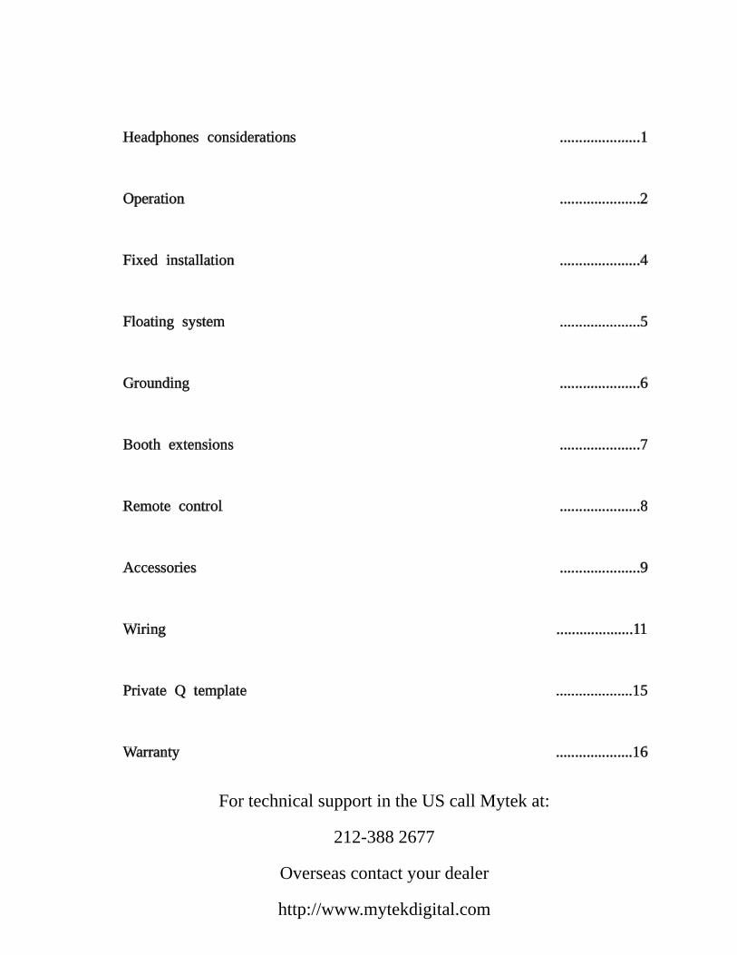
Headphones considerations
Operation
Fixed installation
Floating system
Grounding
Booth extensions
Remote control
Accessories
Wiring
Private Q template
Warranty
.....................1
.....................2
.....................4
.....................5
.....................6
.....................7
.....................8
.....................9
....................11
....................15
....................16
For technical support in the US call Mytek at:
212-388 2677
Overseas contact your dealer
http://www.mytekdigital.com
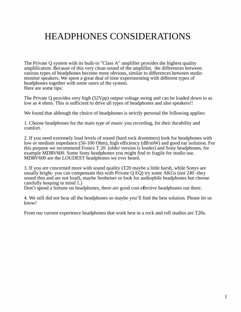
The Private Q system with its built-in "Class A" amplifier provides the highest quality amplification. Because of this very clean sound of the amplifier, the differences between various types of headphones become more obvious, similar to differences between studio monitor speakers. We spent a great deal of time experimenting with different types of headphones together with some users of the system. Here are some tips:
The Private Q provides very high (52Vpp) output voltage swing and can be loaded down to as low as 4 ohms. This is sufficient to drive all types of headphones and also speakers!!
We found that although the choice of headphones is strictly personal the following applies:
1. Choose headphones for the main type of music you recording, for their durability and comfort.
2. If you need extremely loud levels of sound (hard rock drummers) look for headphones with low or medium impedance (50-100 Ohm), high efficiency (dB/mW) and good ear isolation. For this purpose we recommend Fostex T 20 (older version is louder) and Sony headphones, for example MDRV600. Some Sony headphones you might find to fragile for studio use. MDRV600 are the LOUDEST headphones we ever heard.
3. If you are concerned more with sound quality (T20 maybe a little harsh, while Sonys are usually bright- you can compensate this with Private Q EQ) try some AKGs (not 240 -they sound thin and are not loud), maybe Senheiser or look for audiophile headphones but choose carefully keeping in mind 1.)Don’t spend a fortune on headphones, there are good cost effective headphones out there.
4. We still did not hear all the headphones so maybe you’ll find the best solution. Please let us know!
From our current experience headphones that work best in a rock and roll studios are T20s.
1
HEADPHONES CONSIDERATIONS
OPERATION
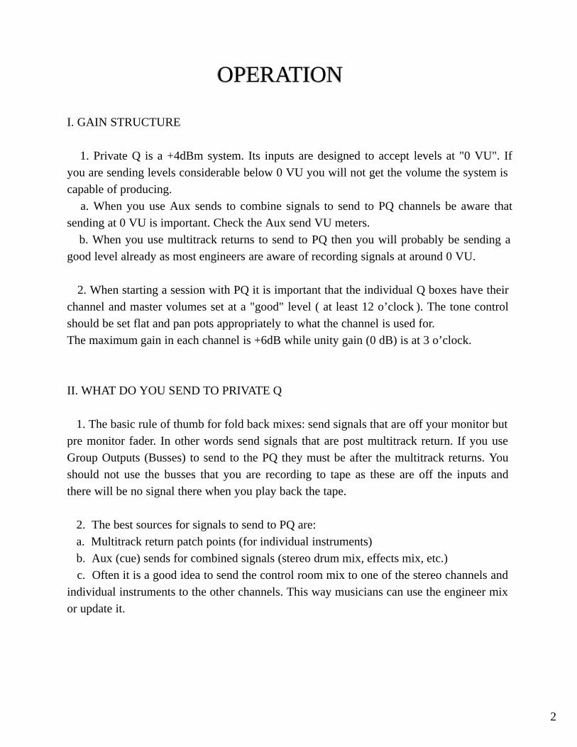
I. GAIN STRUCTURE
1. Private Q is a +4dBm system. Its inputs are designed to accept levels at "0 VU". If
you are sending levels considerable below 0 VU you will not get the volume the system is
capable of producing.
a. When you use Aux sends to combine signals to send to PQ channels be aware that
sending at 0 VU is important. Check the Aux send VU meters.
b. When you use multitrack returns to send to PQ then you will probably be sending a
good level already as most engineers are aware of recording signals at around 0 VU.
2. When starting a session with PQ it is important that the individual Q boxes have their
channel and master volumes set at a "good" level ( at least 12 o’clock ). The tone control
should be set flat and pan pots appropriately to what the channel is used for.
The maximum gain in each channel is +6dB while unity gain (0 dB) is at 3 o’clock.
II. WHAT DO YOU SEND TO PRIVATE Q
1. The basic rule of thumb for fold back mixes: send signals that are off your monitor but
pre monitor fader. In other words send signals that are post multitrack return. If you use
Group Outputs (Busses) to send to the PQ they must be after the multitrack returns. You
should not use the busses that you are recording to tape as these are off the inputs and
there will be no signal there when you play back the tape.
2. The best sources for signals to send to PQ are:
a. Multitrack return patch points (for individual instruments)
b. Aux (cue) sends for combined signals (stereo drum mix, effects mix, etc.)
c. Often it is a good idea to send the control room mix to one of the stereo channels and
individual instruments to the other channels. This way musicians can use the engineer mix
or update it.
2
III. TALKBACK
1. We will give an example with the SSL console but it is similar in all consoles:
Talkback to headphones usually occurs inside the SSL and is inserted into Aux sends
at the patch point called CUE SENDS or CUE OUTPUTS not the CUE INSERTS. Any
time you use the Cue Sends as a way to feed some signal to PQ then talkback to Cues will
get to the musicians at some level when the engineer presses the "Cues" talkback button.
2. A good idea if you have a spare channel on the Q mixer is to dedicate that channel as
a "Talkback" and patch any of the Cue send/output patch points into it. That way each
musician has a level control for talkback and you are not relying on them to have any other
specific channel turned up. This does not disable this send as an echo send.
IV. OPERATION
1. Operation of the Private Q mixers is very simple and self explanatory to you.
However you cannot assume that it is self-explanatory to every musician who will be using
it. Some may have no problems, some may have no idea! A few simple things that the
assistant can do at the beginning of the session will help:
a. Properly label all Q boxes with artist tape and sharpie.
b. Preset all volume pots at around 12 o’clock, tone controls flat, and pan pots
appropriately. As the engineer starts getting sounds assistant can go around with a set of
headphones and help the musicians get the mix up. It is a good idea to talk to each
musician for a minute and show them how the thing works and what is on each channel.
DO NOT EVER HOT PLUG the cue cables !! They carry power for the boxes andoccurring sparks will DAMAGE the connectors and possibly the boxes. First set upthe system, then power it up. If you have to add a box it is OK to turn off the system.
3
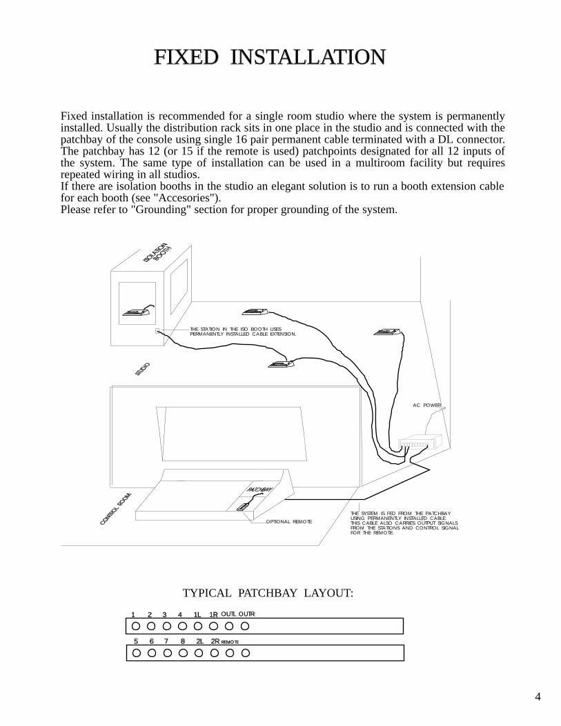
FIXED INSTALLATION
Fixed installation is recommended for a single room studio where the system is permanently installed. Usually the distribution rack sits in one place in the studio and is connected with the patchbay of the console using single 16 pair permanent cable terminated with a DL connector. The patchbay has 12 (or 15 if the remote is used) patchpoints designated for all 12 inputs of the system. The same type of installation can be used in a multiroom facility but requires repeated wiring in all studios.If there are isolation booths in the studio an elegant solution is to run a booth extension cable for each booth (see "Accesories"). Please refer to "Grounding" section for proper grounding of the system.
1 2 3 4 1L 1R
5 6 7 8 2L 2R
OUTL OUTR
REMOTE
TYPICAL PATCHBAY LAYOUT:
OPTIONAL REMOTE
THE STATION IN THE ISO BOOTH USESPERMANENTLY INSTALLED CABLE EXTENSION.
THE SYSTEM IS FED FROM THE PATCHBAYUSING PERMANENTLY INSTALLED CABLE.THIS CABLE ALSO CARRIES OUTPUT SIGNALSFROM THE STATIONS AND CONTROL SIGNAL FOR THE REMOTE.
AC POWER
4
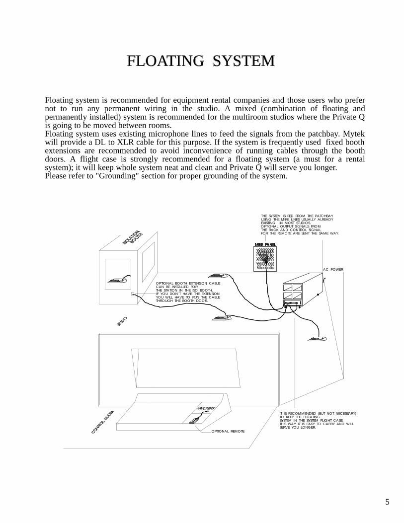
FLOATING SYSTEM
Floating system is recommended for equipment rental companies and those users who prefer not to run any permanent wiring in the studio. A mixed (combination of floating and permanently installed) system is recommended for the multiroom studios where the Private Q is going to be moved between rooms. Floating system uses existing microphone lines to feed the signals from the patchbay. Mytek will provide a DL to XLR cable for this purpose. If the system is frequently used fixed booth extensions are recommended to avoid inconvenience of running cables through the booth doors. A flight case is strongly recommended for a floating system (a must for a rental system); it will keep whole system neat and clean and Private Q will serve you longer.Please refer to "Grounding" section for proper grounding of the system.
OPTIONAL REMOTE
OPTIONAL BOOTH EXTENSION CABLECAN BE INSTALLED FORTHE STATION IN THE ISO BOOTH.IF YOU DON’T HAVE THE EXTENSIONYOU WILL HAVE TO RUN THE CABLE THROUGH THE BOOTH DOOR.
THE SYSTEM IS FED FROM THE PATCHBAYUSING THE MIKE LINES USUALLY ALREADY EXISTING IN MOST STUDIOS.OPTIONAL OUTPUT SIGNALS FROM THE RACK AND CONTROL SIGNAL FOR THE REMOTE ARE SENT THE SAME WAY.
AC POWER
MIKE PANEL
IT IS RECOMMENDED (BUT NOT NECESSARY)TO KEEP THE FLOATING SYSTEM IN THE SYSTEM FLIGHT CASE.THIS WAY IT IS EASY TO CARRY AND WILLSERVE YOU LONGER.
5
GROUNDING
As most professional systems the Private Q uses +4dBm balanced shielded lines and the grounding is configured on the "STAR" principle. This means that all grounds and shields meet in one central point inside the distribution rack and nowhere else to avoid ground loops. For instance:
1. All the cables connecting the PQ mixers have the individual shields connected on both connectors so it doesn’t matter which end goes where. All shields of all the cables are grounded at the rack side.Inside each PQ mixer the shields are disconnected from the ground and the mixer sees the ground reference only through the main drain wire (called on the schematics GND).Each PQ mixer chassis is grounded through this drain wire.
2. The second DL on each mixer still feeds the shields through so when few units are daisy-chained all of the individual cable shields are still grounded at the rack side.
3. Rack chassis is always connected to the central ground point inside the rack.The power plug should be lifted if the input ground is connected to the system ground.4. In a floating system the shields of the rack’s input cable are connected on both sides (DL and pin 1 of all XLRs). The main drain wire is connected to the central ground point and has an "alligator" clip on the other side. This clip should be connected by the user to the studio’s ground.
5. In a permanently installed system the shields of the input cable (except the control wire #15) MUST NOT be connected. The drain wire however MUST be connected to the main studio’s ground point. It usually has to be extended using an insulated thick wire.
6. Properly installed system should be absolutely quiet.
7. PQ mixer output XLRs come from the factory with pin 1 disconnected. You may connect it if necessary by opening the mixer and soldering the pin to the designated point on the printed circuit board.
8. If you hear loud hum in one channel of a PQ mixer it is usually not related to grounding but one of the channel wires (either hot or cold) is not making contact.Try resetting the DL, if it does not help check the cable.
6
BOOTH EXTENSIONS
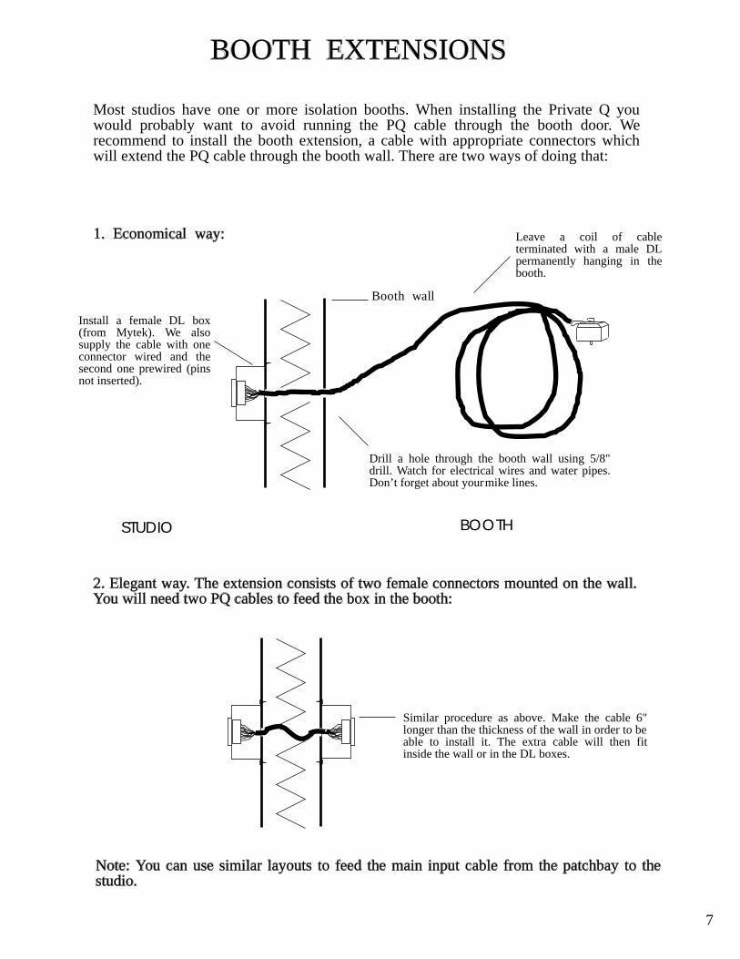
Most studios have one or more isolation booths. When installing the Private Q you would probably want to avoid running the PQ cable through the booth door. We recommend to install the booth extension, a cable with appropriate connectors which will extend the PQ cable through the booth wall. There are two ways of doing that:
1. Economical way:
Booth wall
Drill a hole through the booth wall using 5/8" drill. Watch for electrical wires and water pipes. Don’t forget about your mike lines.
Install a female DL box (from Mytek). We also supply the cable with one connector wired and the second one prewired (pins not inserted).
Leave a coil of cable terminated with a male DL permanently hanging in the booth.
STUDIO BOOTH
2. Elegant way. The extension consists of two female connectors mounted on the wall. You will need two PQ cables to feed the box in the booth:
Similar procedure as above. Make the cable 6" longer than the thickness of the wall in order to be able to install it. The extra cable will then fit inside the wall or in the DL boxes.
Note: You can use similar layouts to feed the main input cable from the patchbay to the studio.
7
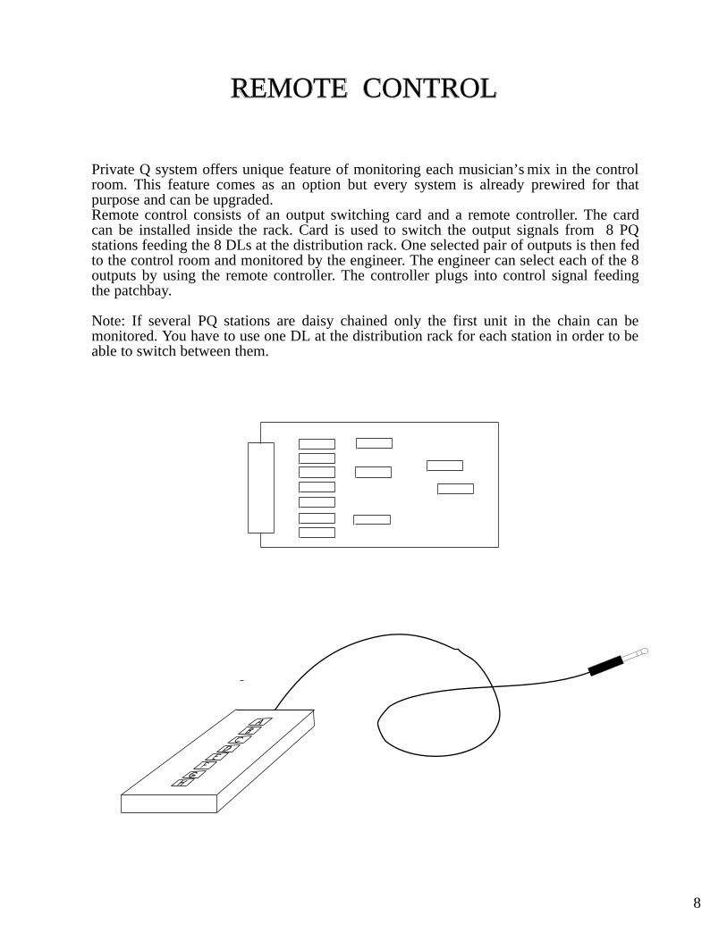
REMOTE CONTROL
Private Q system offers unique feature of monitoring each musician’s mix in the control room. This feature comes as an option but every system is already prewired for that purpose and can be upgraded. Remote control consists of an output switching card and a remote controller. The card can be installed inside the rack. Card is used to switch the output signals from 8 PQ stations feeding the 8 DLs at the distribution rack. One selected pair of outputs is then fed to the control room and monitored by the engineer. The engineer can select each of the 8 outputs by using the remote controller. The controller plugs into control signal feeding the patchbay.
Note: If several PQ stations are daisy chained only the first unit in the chain can be monitored. You have to use one DL at the distribution rack for each station in order to be able to switch between them.
8
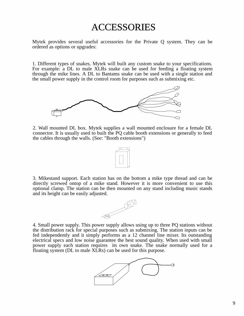
ACCESSORIESMytek provides several useful accessories for the Private Q system. They can be ordered as options or upgrades:
1. Different types of snakes. Mytek will built any custom snake to your specifications. For example: a DL to male XLRs snake can be used for feeding a floating system through the mike lines. A DL to Bantams snake can be used with a single station and the small power supply in the control room for purposes such as submixing etc.
2. Wall mounted DL box. Mytek supplies a wall mounted enclosure for a female DL connector. It is usually used to built the PQ cable booth extensions or generally to feed the cables through the walls. (See: "Booth extensions")
3. Mikestand support. Each station has on the bottom a mike type thread and can be directly screwed ontop of a mike stand. However it is more convenient to use this optional clamp. The station can be then mounted on any stand including music stands and its height can be easily adjusted.
4. Small power supply. This power supply allows using up to three PQ stations without the distribution rack for special purposes such as submixing. The station inputs can be fed independently and it simply performs as a 12 channel line mixer. Its outstanding electrical specs and low noise guarantee the best sound quality. When used with small power supply each station requires its own snake. The snake normally used for a floating system (DL to male XLRs) can be used for this purpose.
9
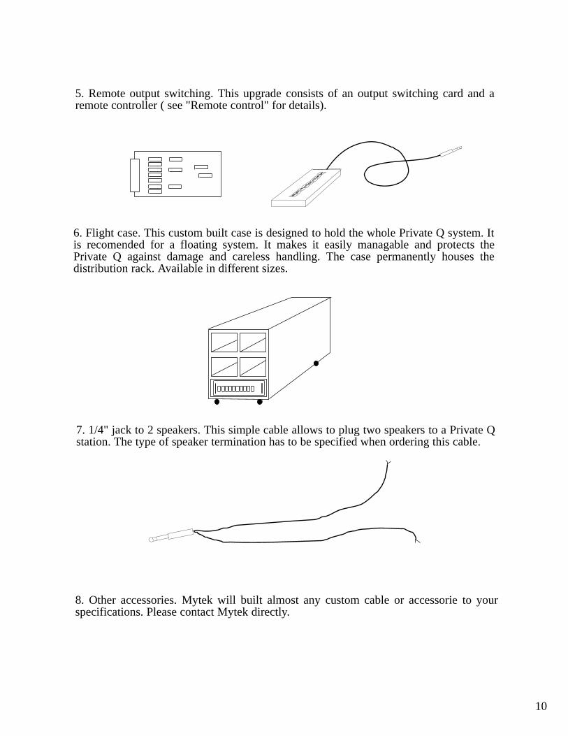
5. Remote output switching. This upgrade consists of an output switching card and a remote controller ( see "Remote control" for details).
6. Flight case. This custom built case is designed to hold the whole Private Q system. It is recomended for a floating system. It makes it easily managable and protects the Private Q against damage and careless handling. The case permanently houses the distribution rack. Available in different sizes.
7. 1/4" jack to 2 speakers. This simple cable allows to plug two speakers to a Private Q station. The type of speaker termination has to be specified when ordering this cable.
8. Other accessories. Mytek will built almost any custom cable or accessorie to your specifications. Please contact Mytek directly.
10
1 2 3 4 5 6
A
B
C
D
E
F
G
H
J
K
1 2 3 4 5 6
1+ 1- 1s
2+ 2- 2s
3+ 3- 3s
4+ 4- 4s
5+ 5- 5s
6+ 6- 6s
7+ 7- 7s
8+ 8- 8s
9+ 9- 9s
10+ 10- 10s
11+ 11- 11s
12+ 12- 12s
13+ 13- 13s 14+ 14- 14s
15 1515 151515
16 1616 1616 16
GNDGND GND GND GND GND
1 2 3 4 5 6
A
B
C
D
E
F
G
H
J
K
1 2 3 4 5 6
1
2+
3+
2-
1- 1s
2s
3- 3s
4+ 4- 4s
5+ 5- 5s
6+ 6- 6s
OL+ OL- OLs
+29V +29V+29V+29V+29V+29V
GNDGND GND GND GND GND
-29V-29V -29V -29V -29V -29V
OR+OR- ORs
7+ 7- 7s
8+ 8- 8s
1L+ 1L- 1Ls
1R+ 1R- 1Rs
2L+ 2L- 2Ls
2R+ 2R- 2Rs
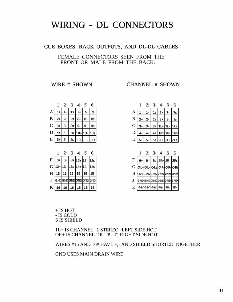
WIRING - DL CONNECTORS
CUE BOXES, RACK OUTPUTS, AND DL-DL CABLES
FEMALE CONNECTORS SEEN FROM THEFRONT OR MALE FROM THE BACK.
WIRE # SHOWN CHANNEL # SHOWN
11
+ IS HOT- IS COLDS IS SHIELD
1L+ IS CHANNEL "1 STEREO" LEFT SIDE HOTOR+ IS CHANNEL ’OUTPUT" RIGHT SIDE HOT
WIRES #15 AND 16# HAVE +,- AND SHIELD SHORTED TOGETHER
GND USES MAIN DRAIN WIRE
+ IS HOT- IS COLDS IS SHIELD
1L+ IS CHANNEL "1 STEREO" LEFT SIDE HOTOR+ IS CHANNEL ’OUTPUT" RIGHT SIDE HOT
WIRES #15 AND 16# HAVE +,- AND SHIELD SHORTED TOGETHER
GND USES MAIN DRAIN WIRE
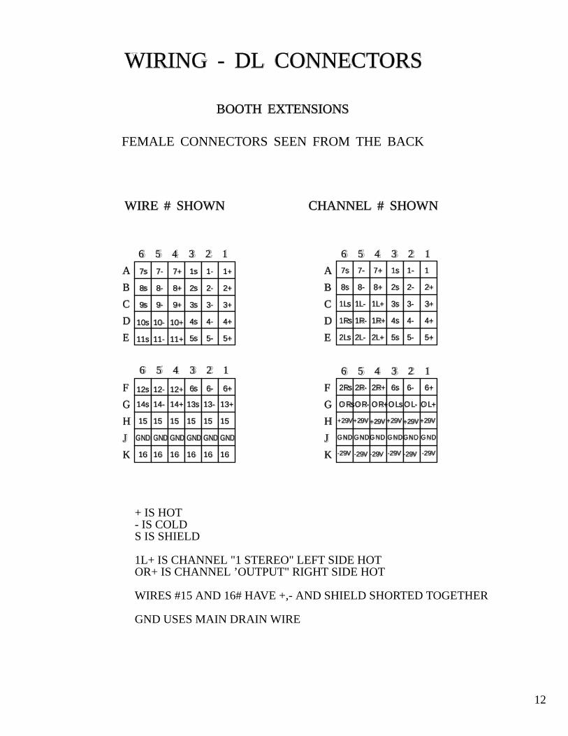
WIRING - DL CONNECTORS
BOOTH EXTENSIONS
FEMALE CONNECTORS SEEN FROM THE BACK
WIRE # SHOWN CHANNEL # SHOWN
123456
123456
A
B
C
D
E
F
G
H
J
K
1+1-1s
2+2-2s
3+3-3s
4+4-4s
5+5-5s
6+6-6s
7+7-7s
8+8-8s
9+9-9s
10+10-10s
11+11-11s
12+12-12s
13+13-13s14+14-14s
1515 1515 15 15
1616 1616 1616
GND GNDGNDGNDGNDGND
123456
123456
A
B
C
D
E
F
G
H
J
K
1
2+
3+
2-
1-1s
2s
3-3s
4+4-4s
5+5-5s
6+6-6s
OL+OL-OLs
+29V+29V+29V+29V+29V +29V
GNDGNDGNDGNDGNDGND
-29V-29V-29V-29V-29V-29V
OR+OR-ORs
7+7-7s
8+8-8s
1L+1L-1Ls
1R+1R-1Rs
2L+2L-2Ls
2R+2R-2Rs
12
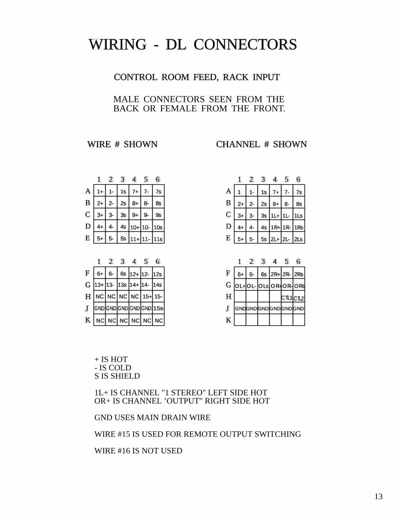
+ IS HOT- IS COLDS IS SHIELD
1L+ IS CHANNEL "1 STEREO" LEFT SIDE HOTOR+ IS CHANNEL ’OUTPUT" RIGHT SIDE HOT
GND USES MAIN DRAIN WIRE
WIRE #15 IS USED FOR REMOTE OUTPUT SWITCHING
WIRE #16 IS NOT USED
1 2 3 4 5 6
A
B
C
D
E
F
G
H
J
K
1 2 3 4 5 6
1+ 1- 1s
2+ 2- 2s
3+ 3- 3s
4+ 4- 4s
5+ 5- 5s
6+ 6- 6s
7+ 7- 7s
8+ 8- 8s
9+ 9- 9s
10+ 10- 10s
11+ 11- 11s
12+ 12- 12s
13+ 13- 13s 14+ 14- 14s
NC 15-NC 15+NCNC
NC NCNC NCNC NC
15sGND GND GND GND GND
1 2 3 4 5 6
A
B
C
D
E
F
G
H
J
K
1 2 3 4 5 6
1
2+
3+
2-
1- 1s
2s
3- 3s
4+ 4- 4s
5+ 5- 5s
6+ 6- 6s
OL+ OL- OLs
GNDGND GND GND GND GND
OR+OR- ORs
7+ 7- 7s
8+ 8- 8s
1L+ 1L- 1Ls
1R+ 1R- 1Rs
2L+ 2L- 2Ls
2R+ 2R- 2Rs
WIRING - DL CONNECTORS
CONTROL ROOM FEED, RACK INPUT
MALE CONNECTORS SEEN FROM THEBACK OR FEMALE FROM THE FRONT.
WIRE # SHOWN CHANNEL # SHOWN
CTL1 CTL2
13
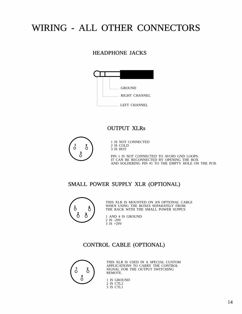
WIRING - ALL OTHER CONNECTORS
HEADPHONE JACKS
GROUND
RIGHT CHANNEL
LEFT CHANNEL
OUTPUT XLRs
1 2
3
1 2
3
1
2 3
4
SMALL POWER SUPPLY XLR (OPTIONAL)
CONTROL CABLE (OPTIONAL)
1 IS NOT CONNECTED2 IS COLD3 IS HOT
PIN 1 IS NOT CONNECTED TO AVOID GND LOOPS. IT CAN BE RECONNECTED BY OPENING THE BOX AND SOLDERING PIN #1 TO THE EMPTY HOLE ON THE PCB.
THIS XLR IS MOUNTED ON AN OPTIONAL CABLE WHEN USING THE BOXES SEPARATELY FROM THE RACK WITH THE SMALL POWER SUPPLY.
1 AND 4 IS GROUND2 IS -29V3 IS +29V
THIS XLR IS USED IN A SPECIAL CUSTOMAPPLICATIONS TO CARRY THE CONTROL SIGNAL FOR THE OUTPUT SWITCHING REMOTE.
1 IS GROUND2 IS CTL23 IS CTL1
14
1
2 3 4
1
2
3
4
0
LR
1
2 3 4
1
2 3 4
0
LR
1
2 3 4
1
2
3 4
0
LR
1
2 3 4
1
2
3
4
0
LR
1
2 3 4
1
2
3
4
0
LR
1
2 3 4
1
2 3 4
0
LR
1
2 3 4
1
2 3 4
0
LR
1
2 3 4
1
2
3 4
0
LR
6
7 8 9
4
3
2
1
56
7 8 9
4
3 2 1
56
7 8 9
4
3
2 1
56
7 8 9
4
3 2 1
56
7 8 9
4
3
2
1
56
7 8 9
4
3
2
1
56
7 8 9
4
3 2 1
56
7 8 9
4
3
2 1
56
7 8 9
4
3
2
1
56
7 8 9
4
3 2 1
56
7 8 9
4
3 2 1
5
_ 18V
+ 18
V
T ON
E
HI
L O
PE
AK
S TE R
E OS T
E RE O
MAS
TER
12
34
56
78
12
Pri
vate
QM
UL T
I CH
AN
NE L
CU
E S Y
STE M
MY
TE K
T
E CH
NO
L OG
IES
USA
PAN
V OL
1
2 3 4
1
2 3 4
0
+-
1
2 3 4
1
2 3 4
0
+-
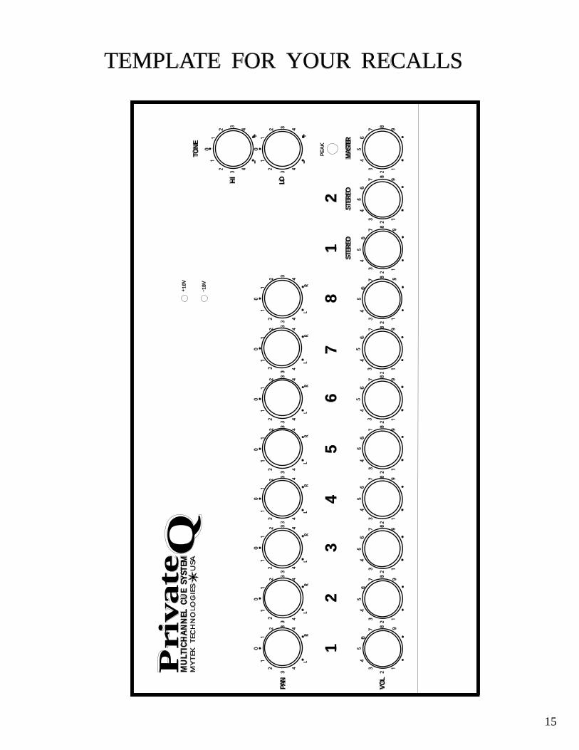
TEMPLATE FOR YOUR RECALLS
15
WARRANTY
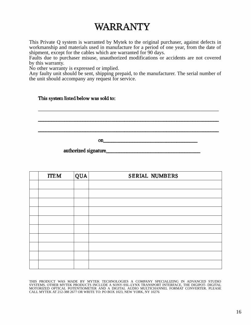
This Private Q system is warranted by Mytek to the original purchaser, against defects in workmanship and materials used in manufacture for a period of one year, from the date of shipment, except for the cables which are warranted for 90 days.Faults due to purchaser misuse, unauthorized modifications or accidents are not covered by this warranty.No other warranty is expressed or implied.Any faulty unit should be sent, shipping prepaid, to the manufacturer. The serial number of the unit should accompany any request for service.
This system listed below was sold to:
_____________________________________________________________________
_____________________________________________________________________
_____________________________________________________________________
on____________________________________
authorized signature____________________________________
ITEM QUA SERIAL NUMBERS
THIS PRODUCT WAS MADE BY MYTEK TECHNOLOGIES A COMPANY SPECIALIZING IN ADVANCED STUDIO SYSTEMS. OTHER MYTEK PRODUCTS INCLUDE A SONY-SSL-LYNX TRANSPORT INTERFACE, THE DIGIPOT- DIGITAL MOTORIZED OPTICAL POTENTIOMETER AND A DIGITAL AUDIO MULTICHANNEL FORMAT CONVERTER. PLEASE CALL MYTEK AT 212-388 2677 OR WRITE TO: PO BOX 1023, NEW YORK, NY 10276
16