Embed Size (px)
Citation preview
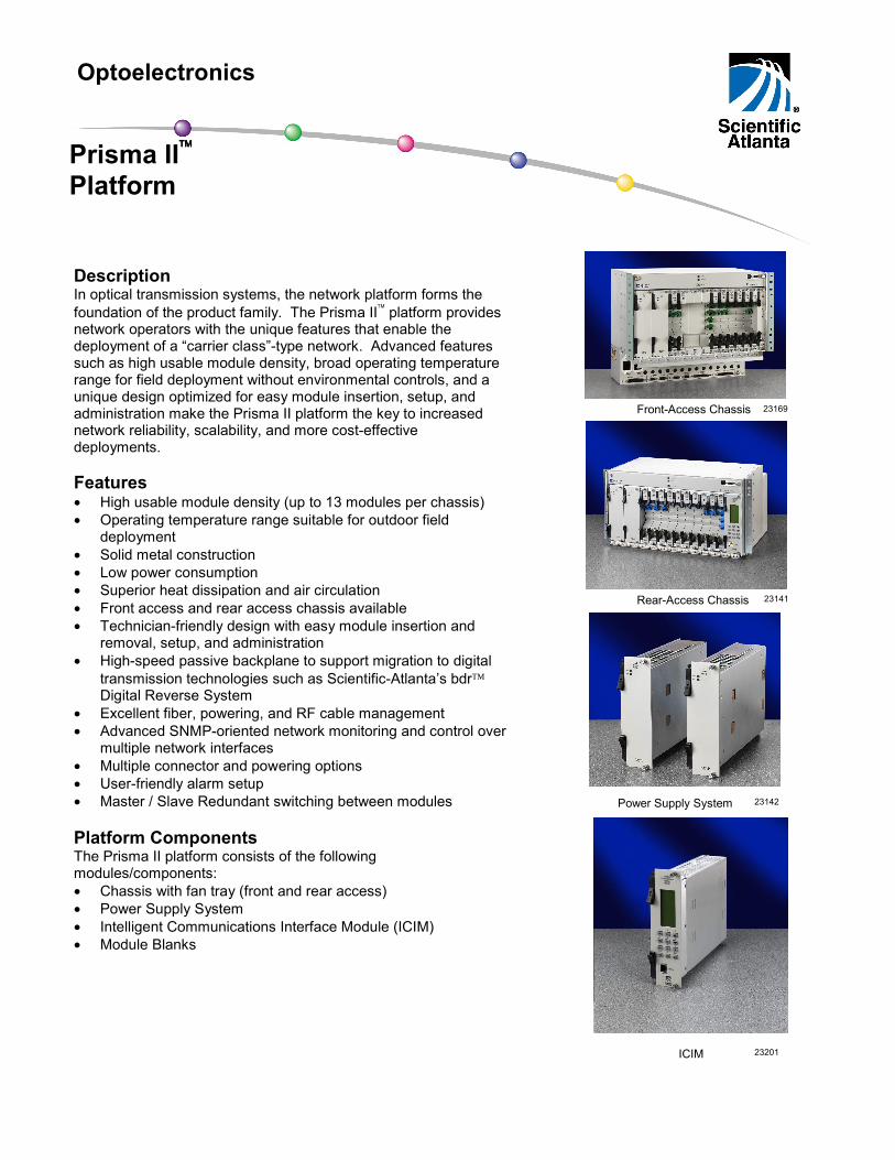
23169 Front-Access Chassis
Power Supply System 23142
ICIM
Rear-Access Chassis
Description In optical transmission systems, the network platform forms the foundation of the product family. The Prisma II platform provides network operators with the unique features that enable the deployment of a “carrier class”-type network. Advanced features such as high usable module density, broad operating temperature range for field deployment without environmental controls, and a unique design optimized for easy module insertion, setup, and administration make the Prisma II platform the key to increased network reliability, scalability, and more cost-effective deployments. Features • High usable module density (up to 13 modules per chassis) • Operating temperature range suitable for outdoor field
deployment • Solid metal construction • Low power consumption • Superior heat dissipation and air circulation • Front access and rear access chassis available • Technician-friendly design with easy module insertion and
removal, setup, and administration • High-speed passive backplane to support migration to digital
transmission technologies such as Scientific-Atlanta’s bdr Digital Reverse System
• Excellent fiber, powering, and RF cable management • Advanced SNMP-oriented network monitoring and control over
multiple network interfaces • Multiple connector and powering options • User-friendly alarm setup • Master / Slave Redundant switching between modules Platform Components The Prisma II platform consists of the following modules/components: • Chassis with fan tray (front and rear access) • Power Supply System • Intelligent Communications Interface Module (ICIM) • Module Blanks
Optoelectronics
Prisma II Platform
23141
23201
2
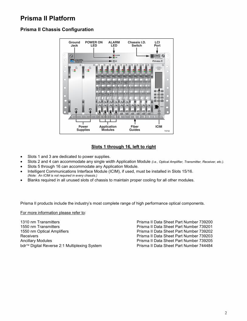
Prisma II Platform Prisma II Chassis Configuration
Slots 1 through 16, left to right • Slots 1 and 3 are dedicated to power supplies. • Slots 2 and 4 can accommodate any single width Application Module (i.e., Optical Amplifier, Transmitter, Receiver, etc.). • Slots 5 through 16 can accommodate any Application Module. • Intelligent Communications Interface Module (ICIM), if used, must be installed in Slots 15/16.
(Note: An ICIM is not required in every chassis.) • Blanks required in all unused slots of chassis to maintain proper cooling for all other modules. Prisma II products include the industry’s most complete range of high performance optical components. For more information please refer to: 1310 nm Transmitters Prisma II Data Sheet Part Number 739200 1550 nm Transmitters Prisma II Data Sheet Part Number 739201 1550 nm Optical Amplifiers Prisma II Data Sheet Part Number 739202 Receivers Prisma II Data Sheet Part Number 739203 Ancillary Modules Prisma II Data Sheet Part Number 739205 bdr Digital Reverse 2:1 Multiplexing System Prisma II Data Sheet Part Number 744484
IntelligentCommunicaitons
InterfaceModule
1 2 3
4 5 6
7 8 9
Entr
Ethernet
0
STAT CFG
ICIM SEL
SHIFT
ENTR MAIN ALRM
ALARM
CHASSIS ID LOCAL CRAFT INTERFACEON
Prisma¤ II
EDFA
Fail
ACT
EDFA
Fail
ACT
EDFA
Fail
ACT
DRR
Fail
ACT
DRR
Fail
ACT
DRR
Fail
ACT
OTM
Fail
ACT
OTM
Fail
ACT
OTM
Fail
ACT
OTM
Fail
ACT
5 9
Can
Alarm
On
ACPowerSupply
Alarm
On
ACPowerSupply
ALARMLED
LCIPort
POWER ONLED
Chassis I.D.Switch
GroundJack
PowerSupplies
ApplicationModules
FiberGuides
ICIMT8702
3
23169
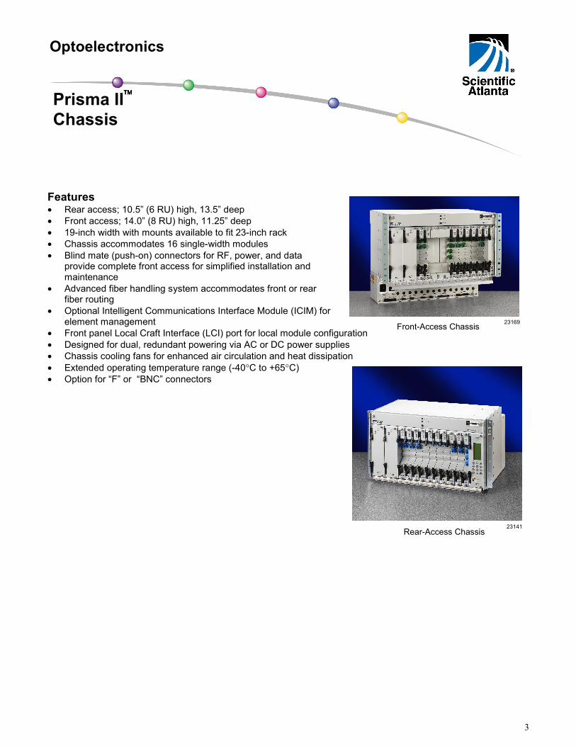
Features • Rear access; 10.5” (6 RU) high, 13.5” deep • Front access; 14.0” (8 RU) high, 11.25” deep • 19-inch width with mounts available to fit 23-inch rack • Chassis accommodates 16 single-width modules • Blind mate (push-on) connectors for RF, power, and data
provide complete front access for simplified installation and maintenance
• Advanced fiber handling system accommodates front or rear fiber routing
• Optional Intelligent Communications Interface Module (ICIM) for element management
• Front panel Local Craft Interface (LCI) port for local module configuration • Designed for dual, redundant powering via AC or DC power supplies • Chassis cooling fans for enhanced air circulation and heat dissipation • Extended operating temperature range (-40°C to +65°C) • Option for “F” or “BNC” connectors
Optoelectronics
Prisma II Chassis
Rear-Access Chassis 23141
Front-Access Chassis
4
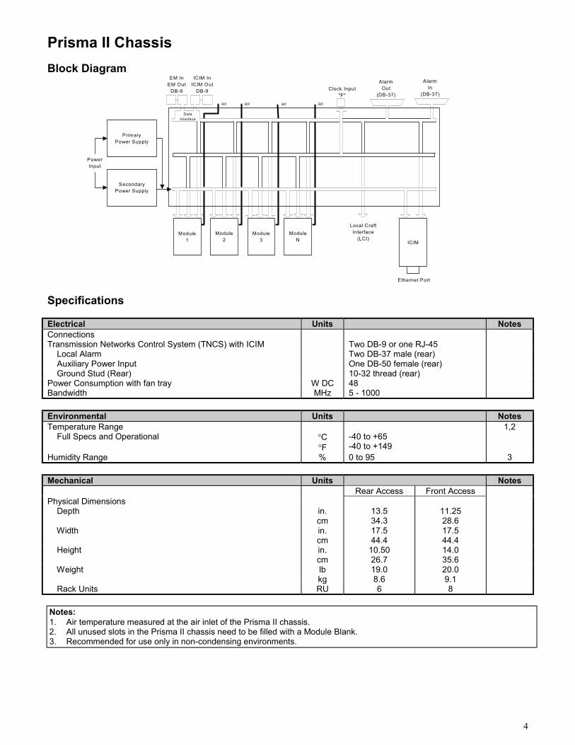
Prisma II Chassis Block Diagram
SecondaryPower Supply
PrimaryPower Supply
Module1
Module2
Module3
ModuleN ICIM
Ethernet Port
ICIM InICIM Out
DB-9
RF
DataInterface
RF RFRF
AlarmIn
(DB-37)
PowerInput
EM InEM Out
DB-9
AlarmOut
(DB-37)Clock Input
"F"
Local CraftInterface
(LCI)
Specifications Electrical Units Notes Connections Transmission Networks Control System (TNCS) with ICIM
Two DB-9 or one RJ-45
Local Alarm Two DB-37 male (rear) Auxiliary Power Input One DB-50 female (rear) Ground Stud (Rear) 10-32 thread (rear) Power Consumption with fan tray W DC 48 Bandwidth MHz 5 - 1000 Environmental Units Notes Temperature Range Full Specs and Operational
°C °F
-40 to +65 -40 to +149
1,2
Humidity Range % 0 to 95 3 Mechanical Units Notes Rear Access Front Access Physical Dimensions Depth
in. cm
13.5 34.3
11.25 28.6
Width in. cm
17.5 44.4
17.5 44.4
Height in. cm
10.50 26.7
14.0 35.6
Weight lb kg
19.0 8.6
20.0 9.1
Rack Units RU 6 8
Notes: 1. Air temperature measured at the air inlet of the Prisma II chassis. 2. All unused slots in the Prisma II chassis need to be filled with a Module Blank. 3. Recommended for use only in non-condensing environments.
5
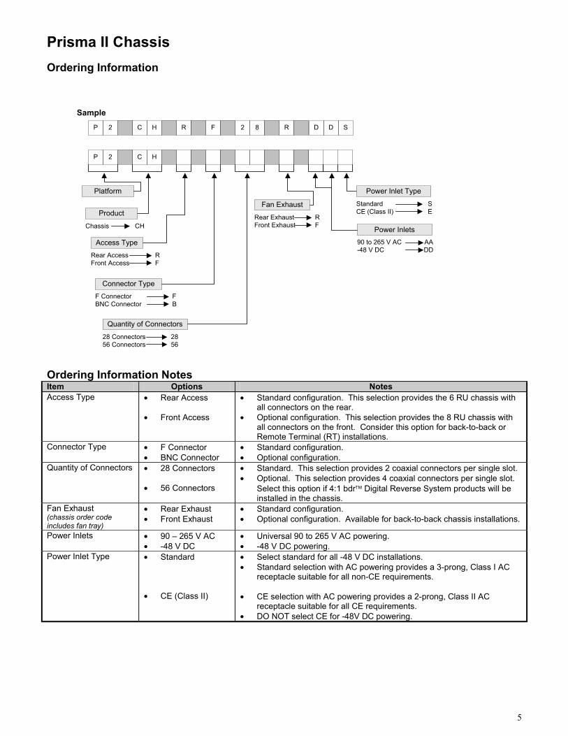
Prisma II Chassis Ordering Information
Ordering Information Notes Item Options Notes Access Type • Rear Access
• Front Access
• Standard configuration. This selection provides the 6 RU chassis with all connectors on the rear.
• Optional configuration. This selection provides the 8 RU chassis with all connectors on the front. Consider this option for back-to-back or Remote Terminal (RT) installations.
Connector Type • F Connector • BNC Connector
• Standard configuration. • Optional configuration.
Quantity of Connectors • 28 Connectors • 56 Connectors
• Standard. This selection provides 2 coaxial connectors per single slot. • Optional. This selection provides 4 coaxial connectors per single slot.
Select this option if 4:1 bdr Digital Reverse System products will be installed in the chassis.
Fan Exhaust (chassis order code includes fan tray)
• Rear Exhaust • Front Exhaust
• Standard configuration. • Optional configuration. Available for back-to-back chassis installations.
Power Inlets • 90 – 265 V AC • -48 V DC
• Universal 90 to 265 V AC powering. • -48 V DC powering.
Power Inlet Type • Standard • CE (Class II)
• Select standard for all -48 V DC installations. • Standard selection with AC powering provides a 3-prong, Class I AC
receptacle suitable for all non-CE requirements. • CE selection with AC powering provides a 2-prong, Class II AC
receptacle suitable for all CE requirements. • DO NOT select CE for -48V DC powering.
Sample
Platform
P 2 C H 2FR R8
P 2 C H
Product
CHChassis
Access TypeRF
Rear AccessFront Access
Connector Type
Quantity of Connectors2856
28 Connectors56 Connectors
FB
F ConnectorBNC Connector
DD S
Power Inlets
Fan ExhaustRF
Rear ExhaustFront Exhaust
Power Inlet TypeSE
StandardCE (Class II)
AADD
90 to 265 V AC-48 V DC
6
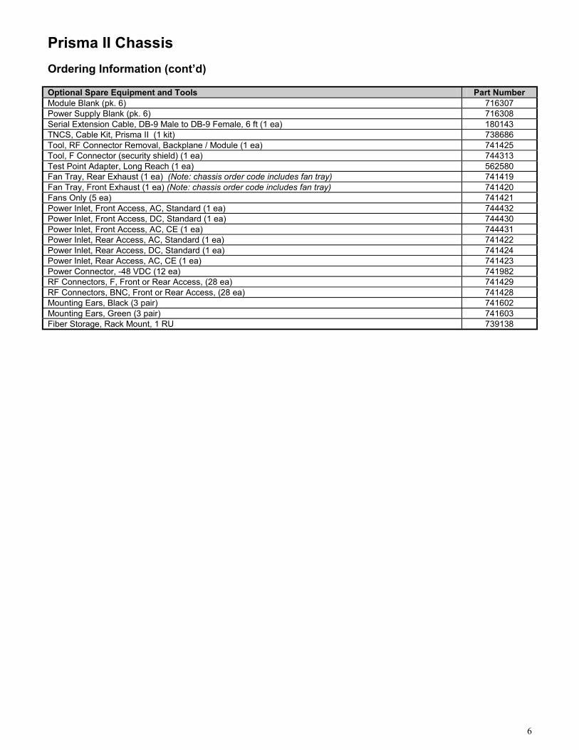
Prisma II Chassis Ordering Information (cont’d) Optional Spare Equipment and Tools Part Number Module Blank (pk. 6) 716307 Power Supply Blank (pk. 6) 716308 Serial Extension Cable, DB-9 Male to DB-9 Female, 6 ft (1 ea) 180143 TNCS, Cable Kit, Prisma II (1 kit) 738686 Tool, RF Connector Removal, Backplane / Module (1 ea) 741425 Tool, F Connector (security shield) (1 ea) 744313 Test Point Adapter, Long Reach (1 ea) 562580 Fan Tray, Rear Exhaust (1 ea) (Note: chassis order code includes fan tray) 741419 Fan Tray, Front Exhaust (1 ea) (Note: chassis order code includes fan tray) 741420 Fans Only (5 ea) 741421 Power Inlet, Front Access, AC, Standard (1 ea) 744432 Power Inlet, Front Access, DC, Standard (1 ea) 744430 Power Inlet, Front Access, AC, CE (1 ea) 744431 Power Inlet, Rear Access, AC, Standard (1 ea) 741422 Power Inlet, Rear Access, DC, Standard (1 ea) 741424 Power Inlet, Rear Access, AC, CE (1 ea) 741423 Power Connector, -48 VDC (12 ea) 741982 RF Connectors, F, Front or Rear Access, (28 ea) 741429 RF Connectors, BNC, Front or Rear Access, (28 ea) 741428 Mounting Ears, Black (3 pair) 741602 Mounting Ears, Green (3 pair) 741603 Fiber Storage, Rack Mount, 1 RU 739138
7
23142
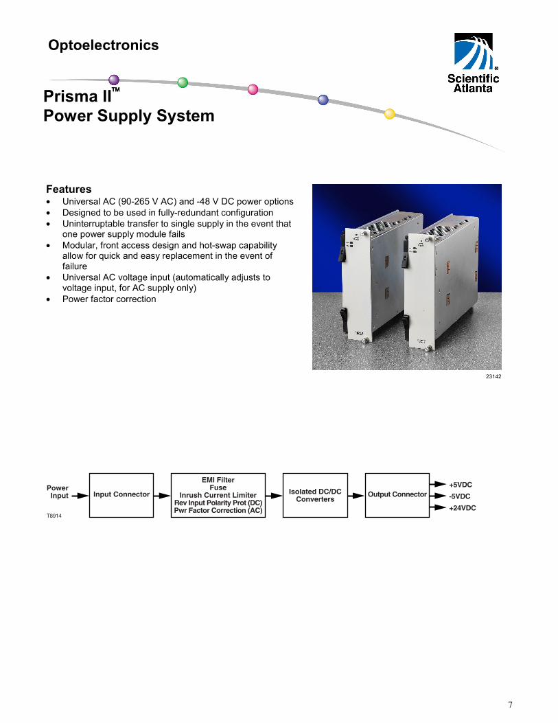
Features • Universal AC (90-265 V AC) and -48 V DC power options • Designed to be used in fully-redundant configuration • Uninterruptable transfer to single supply in the event that
one power supply module fails • Modular, front access design and hot-swap capability
allow for quick and easy replacement in the event of failure
• Universal AC voltage input (automatically adjusts to voltage input, for AC supply only)
• Power factor correction
+24VDCT8914
-5VDC
+5VDCEMI Filter
FuseInrush Current Limiter
Rev Input Polarity Prot (DC)Pwr Factor Correction (AC)
Input Connector Isolated DC/DCConverters
Output ConnectorPower
Input
Optoelectronics
Prisma II Power Supply System
8
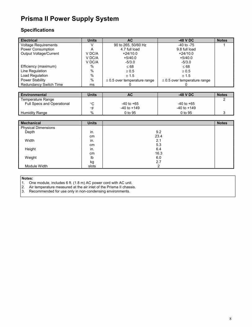
Prisma II Power Supply System Specifications Electrical Units AC -48 V DC Notes Voltage Requirements V 90 to 265, 50/60 Hz -40 to -75 1 Power Consumption A 4.7 full load 9.8 full load Output Voltage/Current V DC/A
V DC/A V DC/A
+24/10.0 +5/40.0 -5/3.0
+24/10.0 +5/40.0 -5/3.0
Efficiency (maximum) % ≤ 68 ≤ 68 Line Regulation % ≥ 0.5 ≥ 0.5 Load Regulation % ± 1.5 ± 1.5 Power Stability % ± 0.5 over temperature range ± 0.5 over temperature range Redundancy Switch Time ms 0 0 Environmental Units AC -48 V DC Notes Temperature Range Full Specs and Operational
°C °F
-40 to +65
-40 to +149
-40 to +65
-40 to +149
2
Humidity Range % 0 to 95 0 to 95 3 Mechanical Units Notes Physical Dimensions Depth
in. cm
9.2
23.4
Width in. cm
2.1 5.3
Height in. cm
6.4 16.3
Weight lb kg
6.0 2.7
Module Width slots 2
Notes: 1. One module, includes 6 ft. (1.8 m) AC power cord with AC unit. 2. Air temperature measured at the air inlet of the Prisma II chassis. 3. Recommended for use only in non-condensing environments.
9
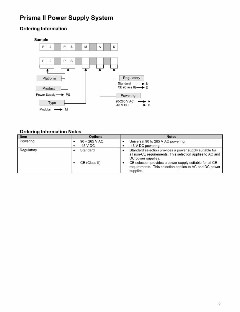
Prisma II Power Supply System Ordering Information
Ordering Information Notes Item Options Notes Powering • 90 – 265 V AC
• -48 V DC • Universal 90 to 265 V AC powering. • -48 V DC powering.
Regulatory • Standard • CE (Class II)
• Standard selection provides a power supply suitable for all non-CE requirements. This selection applies to AC and DC power supplies.
• CE selection provides a power supply suitable for all CE requirements. This selection applies to AC and DC power supplies.
Sample
Platform
Product
PSPower Supply
A SP 2 P S M
Type
MModular
RegulatorySE
StandardCE (Class II)
PoweringAD
90-265 V AC-48 V DC
P 2 SP
10
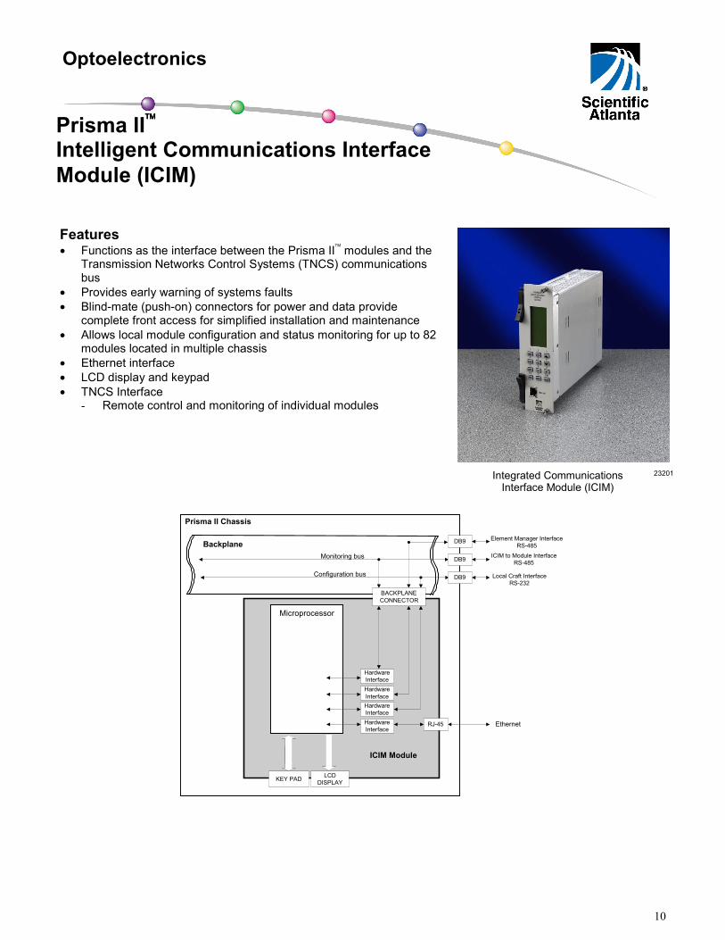
Features • Functions as the interface between the Prisma II modules and the
Transmission Networks Control Systems (TNCS) communications bus
• Provides early warning of systems faults • Blind-mate (push-on) connectors for power and data provide
complete front access for simplified installation and maintenance • Allows local module configuration and status monitoring for up to 82
modules located in multiple chassis • Ethernet interface • LCD display and keypad • TNCS Interface
- Remote control and monitoring of individual modules
Ethernet
Element Manager InterfaceRS-485
Local Craft InterfaceRS-232
Microprocessor
HardwareInterface
Backplane
ICIM Module
Prisma II Chassis
Configuration bus
Monitoring bus
HardwareInterface
HardwareInterface
HardwareInterface
ICIM to Module InterfaceRS-485
RJ-45
KEY PAD LCDDISPLAY
BACKPLANECONNECTOR
DB9
DB9
DB9
Optoelectronics
Prisma II Intelligent Communications Interface Module (ICIM)
23201 Integrated Communications Interface Module (ICIM)
11
Prisma II Intelligent Communications Interface Module (ICIM) Specifications Electrical Units Notes Connections RJ-45 (Ethernet) Power Consumption Nominal Operation Heater ON Operation
W DC W DC
0.3 13.0
Polling Speed Kb 38.4 Environmental Units Notes Temperature Range Full Specs and Operational
°C °F
-40 to +65 -40 to +149
1
Humidity Range % 0 to 95 2 Mechanical Units Notes Physical Dimensions Depth
in. cm
9.8 24.9
Width in. cm
2.1 5.3
Height in. cm
7.6 19.3
Weight lb kg
2.0 0.9
Module Width slot 2
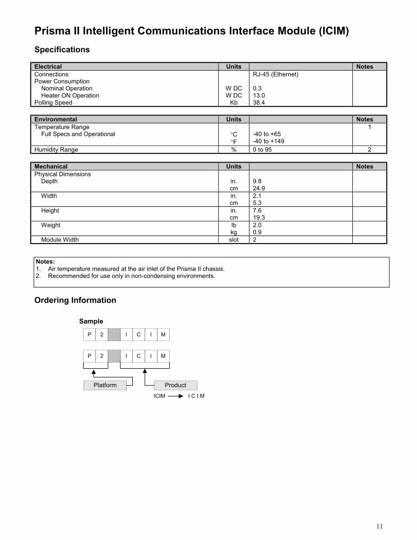
Ordering Information
Notes: 1. Air temperature measured at the air inlet of the Prisma II chassis. 2. Recommended for use only in non-condensing environments.
Sample
Platform Product
I C I MICIM
P 2 I C MI
P 2 I C MI
12
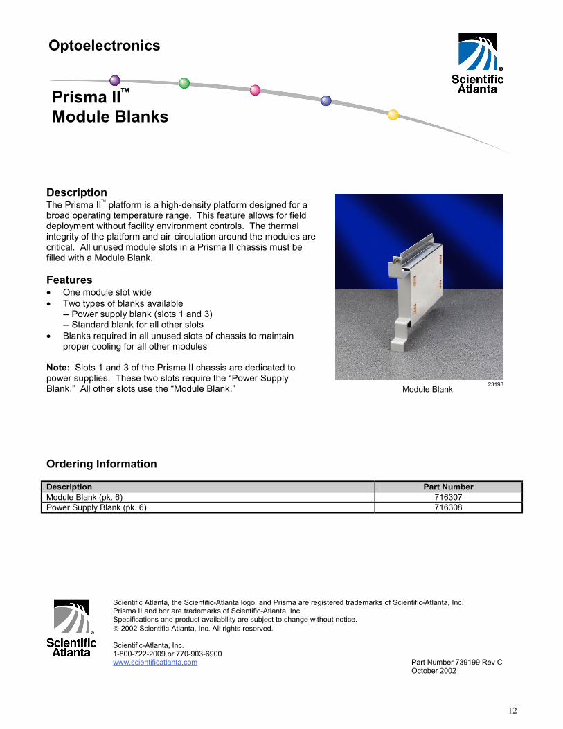
Description The Prisma II platform is a high-density platform designed for a broad operating temperature range. This feature allows for field deployment without facility environment controls. The thermal integrity of the platform and air circulation around the modules are critical. All unused module slots in a Prisma II chassis must be filled with a Module Blank. Features • One module slot wide • Two types of blanks available
-- Power supply blank (slots 1 and 3) -- Standard blank for all other slots
• Blanks required in all unused slots of chassis to maintain proper cooling for all other modules
Note: Slots 1 and 3 of the Prisma II chassis are dedicated to power supplies. These two slots require the “Power Supply Blank.” All other slots use the “Module Blank.” Ordering Information Description Part Number Module Blank (pk. 6) 716307 Power Supply Blank (pk. 6) 716308
Scientific Atlanta, the Scientific-Atlanta logo, and Prisma are registered trademarks of Scientific-Atlanta, Inc. Prisma II and bdr are trademarks of Scientific-Atlanta, Inc. Specifications and product availability are subject to change without notice. 2002 Scientific-Atlanta, Inc. All rights reserved. Scientific-Atlanta, Inc. 1-800-722-2009 or 770-903-6900 www.scientificatlanta.com Part Number 739199 Rev C October 2002
Optoelectronics
Prisma II Module Blanks
Module Blank 23198