Embed Size (px)
Citation preview
Printing techniques
Painettavan elektroniikan jatkokurssi – 15.11.2011Dr. Jukka HastPrincipal Scientist, Team leader, Adjunct ProfessorVTT Technical Research Centre of Finland
217/11/2011
© VTT 2011
Contents
Benefits of printing to for manufacturing of electronics and optics manufacturingPrinting techniques
Gravure printingFlexography printingScreen printingOffset printingInkJet printing
317/11/2011
© VTT 2011
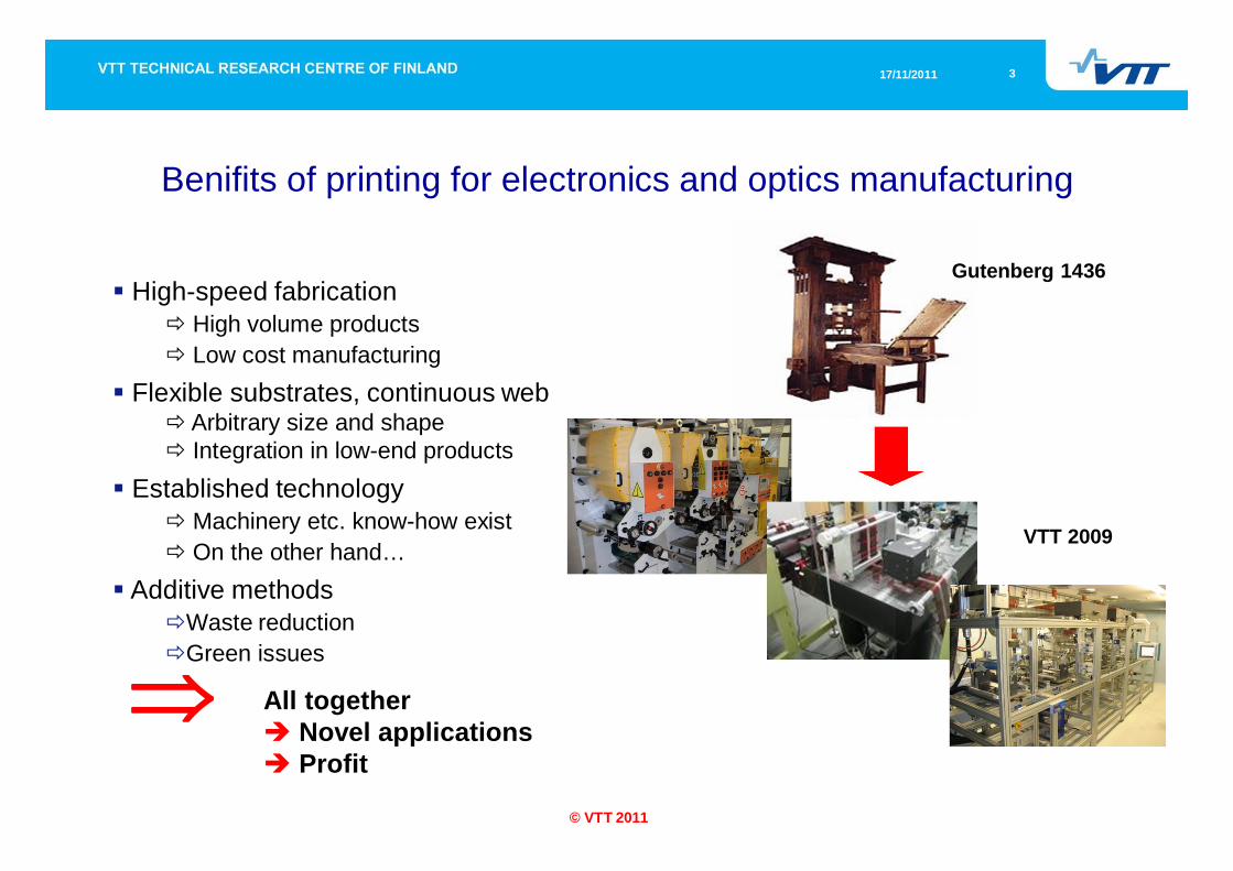
Benifits of printing for electronics and optics manufacturing
Gutenberg 1436
VTT 2009
High-speed fabricationHigh volume productsLow cost manufacturing
Flexible substrates, continuous webArbitrary size and shapeIntegration in low-end products
Established technologyMachinery etc. know-how existOn the other hand…
Additive methodsWaste reductionGreen issues
All togetherNovel applicationsProfit
417/11/2011
© VTT 2011
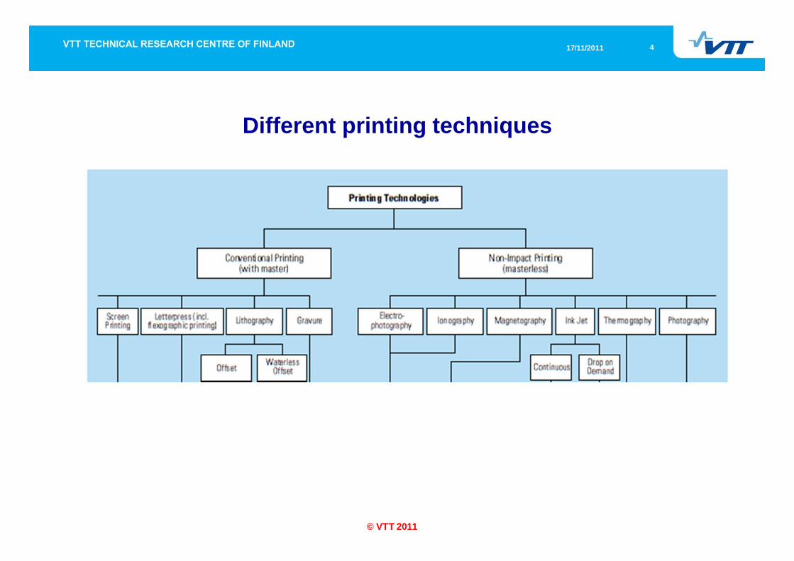
Different printing techniques
517/11/2011
© VTT 2011
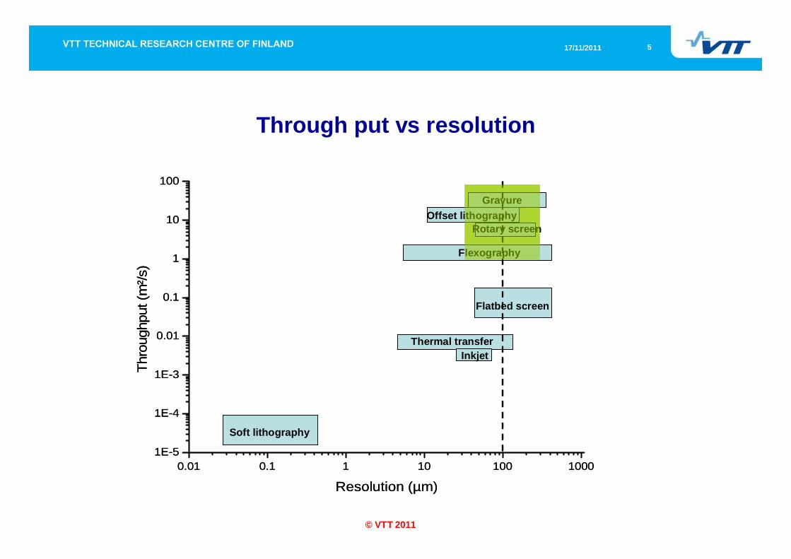
Through put vs resolution
0.01 0.1 1 10 100 10001E-5
1E-4
1E-3
0.01
0.1
1
10
100
Thro
ughp
ut (m
²/s)
Resolution (µm)
GravureOffset lithography
Rotary screen
Flexography
Flatbed screen
Thermal transfer
Soft lithography
Inkjet
0.01 0.1 1 10 100 10001E-5
1E-4
1E-3
0.01
0.1
1
10
100
Thro
ughp
ut (m
²/s)
Resolution (µm)
GravureOffset lithography
Rotary screen
Flexography
Flatbed screen
Thermal transfer
Soft lithography
Inkjet
617/11/2011
© VTT 2011
Gravure printing
Typically used to print high-quality and high-volume publications and packages [1,2]. The advantages of gravure are:
the simple operation principlesimple-structured printing equipmenthigh production speedhigh through-puthigh resolution.
Various solvents can be used since the printing cylinders are resistant to most inks.Disadvantages are:
the high costs of cylinders (> 1K€)high quality demands for substrateshigh requirements for suitable process parameters
1. Kipphan, H., Handbook of print media. Springer-Verlag, Heidelberg, Germany, 2001.
2. Gravure Association of America, Gravure Process and Technology, Rochester NY, 2003.
717/11/2011
© VTT 2011
Operation principle of gravure printing
817/11/2011
© VTT 2011
Operation principle of gravure printing
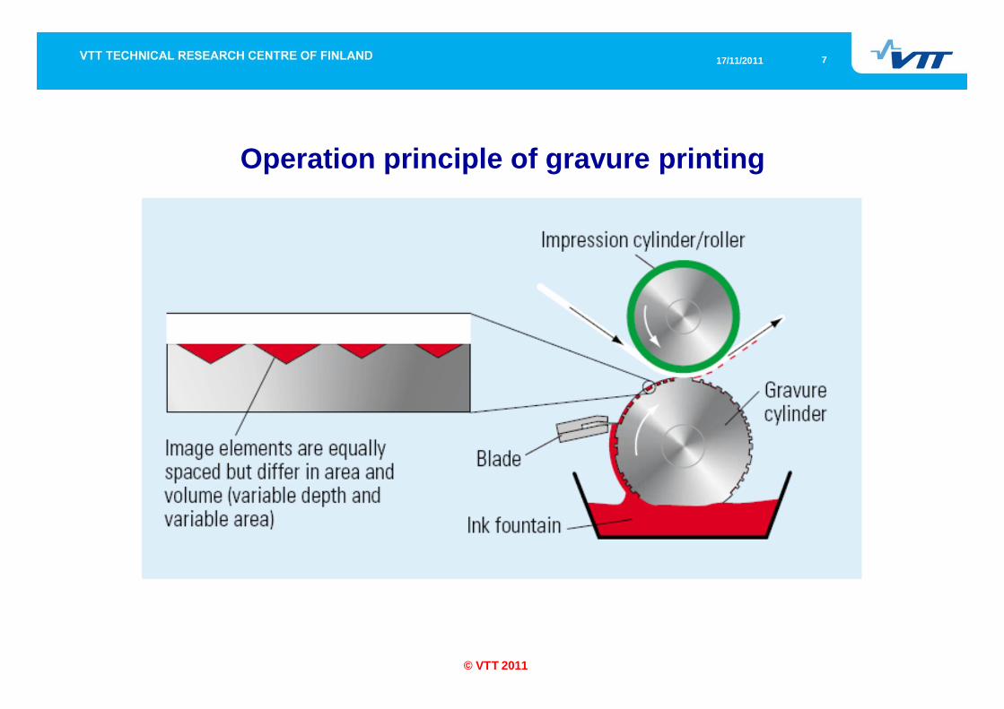
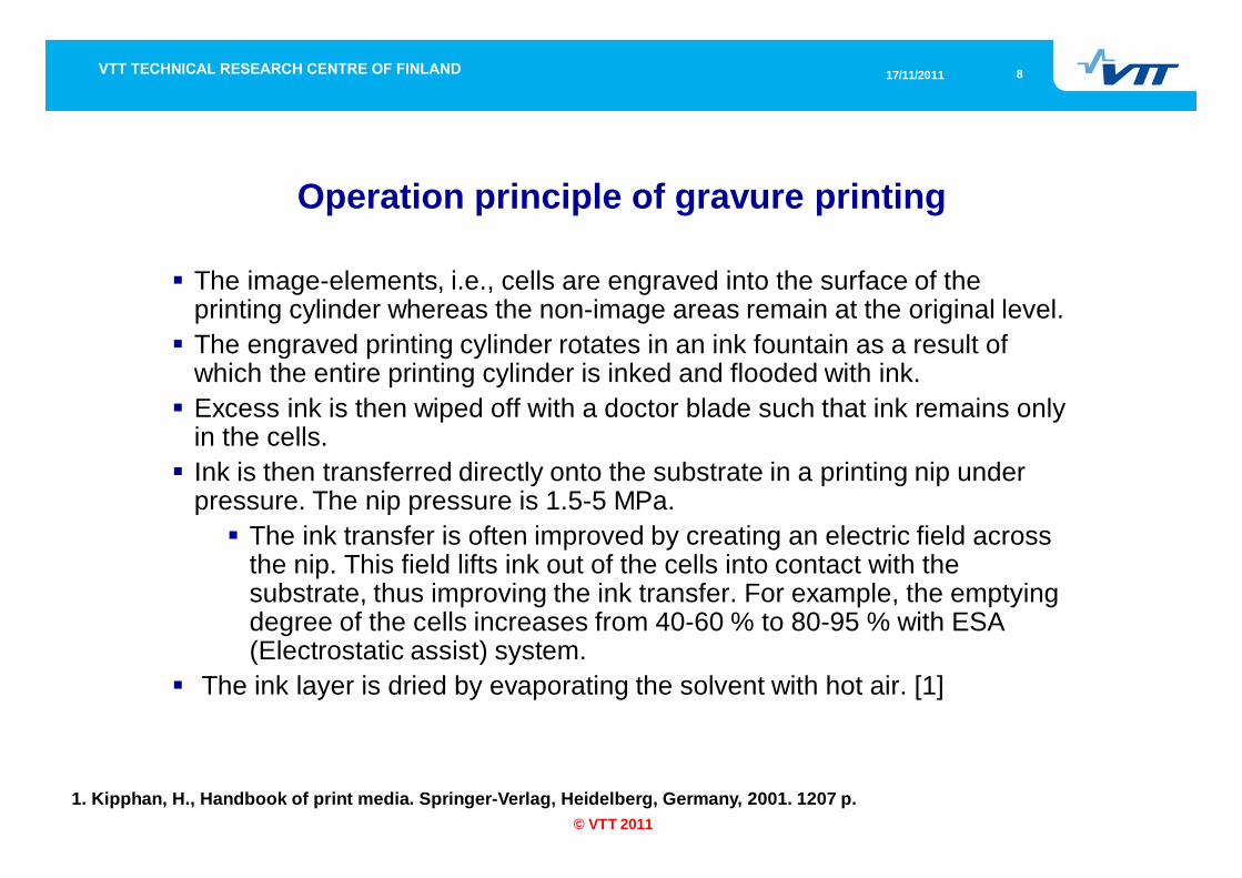
The image-elements, i.e., cells are engraved into the surface of the printing cylinder whereas the non-image areas remain at the original level. The engraved printing cylinder rotates in an ink fountain as a result of which the entire printing cylinder is inked and flooded with ink.Excess ink is then wiped off with a doctor blade such that ink remains only in the cells. Ink is then transferred directly onto the substrate in a printing nip under pressure. The nip pressure is 1.5-5 MPa.
The ink transfer is often improved by creating an electric field across the nip. This field lifts ink out of the cells into contact with the substrate, thus improving the ink transfer. For example, the emptying degree of the cells increases from 40-60 % to 80-95 % with ESA (Electrostatic assist) system.
The ink layer is dried by evaporating the solvent with hot air. [1]
1. Kipphan, H., Handbook of print media. Springer-Verlag, Heidelberg, Germany, 2001. 1207 p.
917/11/2011
© VTT 2011
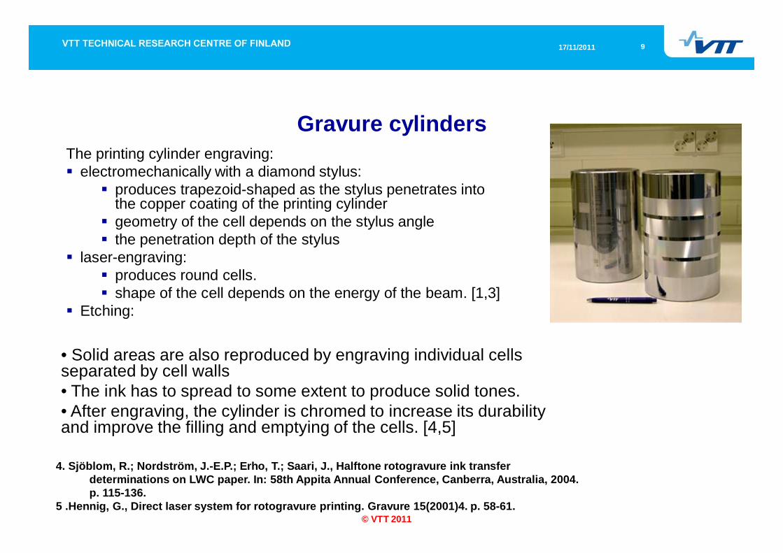
Gravure cylindersThe printing cylinder engraving:
electromechanically with a diamond stylus:produces trapezoid-shaped as the stylus penetrates into the copper coating of the printing cylindergeometry of the cell depends on the stylus anglethe penetration depth of the stylus
laser-engraving: produces round cells. shape of the cell depends on the energy of the beam. [1,3]
Etching:
• Solid areas are also reproduced by engraving individual cells separated by cell walls • The ink has to spread to some extent to produce solid tones.• After engraving, the cylinder is chromed to increase its durability and improve the filling and emptying of the cells. [4,5]
4. Sjöblom, R.; Nordström, J.-E.P.; Erho, T.; Saari, J., Halftone rotogravure ink transfer determinations on LWC paper. In: 58th Appita Annual Conference, Canberra, Australia, 2004. p. 115-136.
5 .Hennig, G., Direct laser system for rotogravure printing. Gravure 15(2001)4. p. 58-61.
1017/11/2011
© VTT 2011
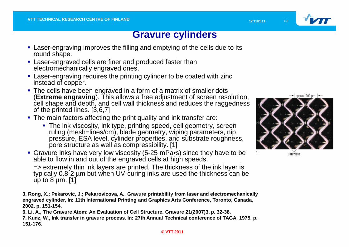
Gravure cylindersLaser-engraving improves the filling and emptying of the cells due to its round shape. Laser-engraved cells are finer and produced faster than electromechanically engraved ones. Laser-engraving requires the printing cylinder to be coated with zinc instead of copper. The cells have been engraved in a form of a matrix of smaller dots (Extreme engraving). This allows a free adjustment of screen resolution, cell shape and depth, and cell wall thickness and reduces the raggedness of the printed lines. [3,6,7]The main factors affecting the print quality and ink transfer are:
The ink viscosity, ink type, printing speed, cell geometry, screen ruling (mesh=lines/cm), blade geometry, wiping parameters, nip pressure, ESA level, cylinder properties, and substrate roughness, pore structure as well as compressibility. [1]
Gravure inks have very low viscosity (5-25 mPa•s) since they have to be able to flow in and out of the engraved cells at high speeds. => extremely thin ink layers are printed. The thickness of the ink layer is typically 0.8-2 µm but when UV-curing inks are used the thickness can be up to 8 µm. [1]
3. Rong, X.; Pekarovic, J.; Pekarovicova, A., Gravure printability from laser and electromechanically engraved cylinder, In: 11th International Printing and Graphics Arts Conference, Toronto, Canada, 2002. p. 151-154.6. Li, A., The Gravure Atom: An Evaluation of Cell Structure. Gravure 21(2007)3. p. 32-38.7. Kunz, W., Ink transfer in gravure process. In: 27th Annual Technical conference of TAGA, 1975. p. 151-176.
1117/11/2011
© VTT 2011
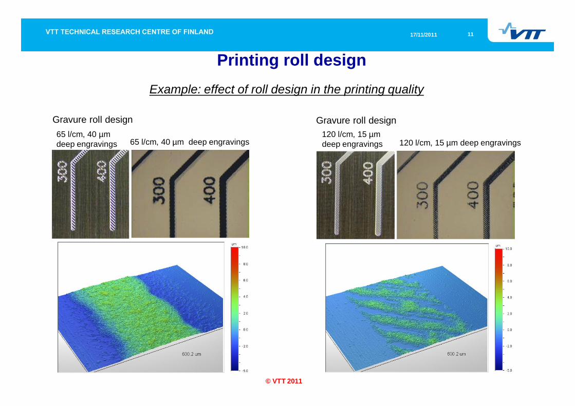
Example: effect of roll design in the printing quality
Printing roll design
65 l/cm, 40 µm deep engravings65 l/cm, 40 µm deep engravings
Gravure roll design
120 l/cm, 15 µm deep engravings120 l/cm, 15 µm deep engravings
Gravure roll design
1217/11/2011
© VTT 2011
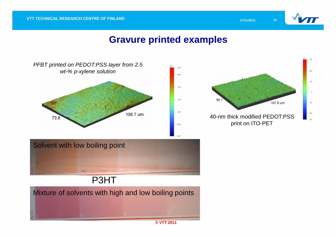
Gravure printed examples
40-nm thick modified PEDOT:PSS print on ITO-PET
Solvent with low boiling point
Mixture of solvents with high and low boiling pointsP3HT
PFBT printed on PEDOT:PSS layer from 2.5 wt-% p-xylene solution
1317/11/2011
© VTT 2011
Flexography printing
used mainly in packaging printing applicationsThe main advantages are:
the wide variety of suitable substratessimple operation principle and press constructionrather accurately adjustable applied amount of ink
Disadvantages include:the lower print qualitypoorer register accuracylower printing speed
compared to other mechanical printing methods. the plate material limits the amount of suitable inks. [8,9]
8. Pekarovicova, A.; Pekarovic, J.; Serafano, J., Flexo printability of publication grades: technical challenges of publication flexography. In: 53rd Annual Technical Conference of TAGA, San Diego, USA, 2001. p. 98-110.
9. Savastano, D., The flexo ink market. Ink world 83(2005)2. p. 48-52.
1417/11/2011
© VTT 2011
Operation principle of flexography printing
1517/11/2011
© VTT 2011
Operation principle of flexography printing
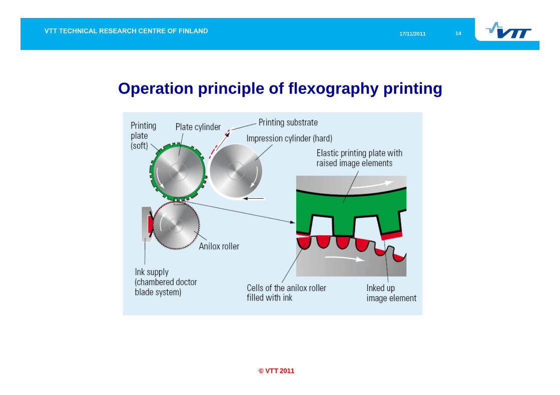
The image elements of the printing plate are raised above the non-image elements, forming a relief pattern of the printed image.Printing ink is applied onto the image elements via an anilox roller that has small cells engraved evenly onto its surface. The surface of the anilox roller is first flooded with ink from an ink chamber after which excess ink is removed with a doctor blade. As a result, ink remains only in the cells. Ink is then transferred onto the raised image elements of the plate and further onto the substrate. The nip pressure is 0.1-0.5 MPa.The plate is made of soft and flexible material which improves the contact formation at the ink transfer points. The ink layer is then dried with hot air. [1]
1617/11/2011
© VTT 2011
Anilox rolls
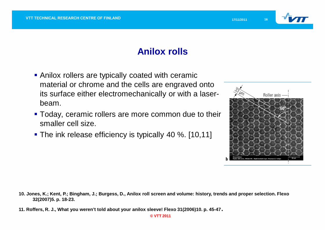
Anilox rollers are typically coated with ceramic material or chrome and the cells are engraved onto its surface either electromechanically or with a laser-beam. Today, ceramic rollers are more common due to their smaller cell size. The ink release efficiency is typically 40 %. [10,11]
10. Jones, K.; Kent, P.; Bingham, J.; Burgess, D., Anilox roll screen and volume: history, trends and proper selection. Flexo32(2007)5. p. 18-23.
11. Roffers, R. J., What you weren’t told about your anilox sleeve! Flexo 31(2006)10. p. 45-47.
1717/11/2011
© VTT 2011
Flexographic printing platesFlexographic printing plates are typically made of photopolymerThese plates are first back-exposed to UV radiation to determine the relief depth. After this, the plate surface is exposed to UV radiation through a film negative. The exposed image areas polymerize and become insoluble. The unexposed material is then removed in a washing stage. CTP (computer-to-plate) plates are imaged directly from digital page data. The plates have a black coating onto which the page negative is formed by ablating it with a laser. Otherwise, the plate making steps are similar to the conventional plates. CTP plates have improved register accuracy. Thermal imaging improves the print quality further. [12-16]
12. Hahn, L. M., Variables in printability and ink transfer in flexography. Ink Maker 81(2003)4. p. 46-50.13. Galton, D., Photopolymer plate characterization. In: 52th Annual Technical Conference of TAGA, Ashville, NC, USA, 2002. p. 109-127.14. Galton, D., Platemaking technologies and trends. Flexo, 32(2007)1. p. 44-48.15. Cherry, J.; Claypole, T. C.; Gethin, D. T., Measurement of the ink release from the anilox roll. In: 58th Annual Technical Conference of
TAGA, Vancouver, B.C., Canada, 2006. p. 395-408.16. Bould, D.C.; Hamblyn, S.M.; Claypole, T.C.; Bohan, M.F.J., The effect of process characteristics on image reproduction in flexographic
printing. In: 33rd International research conference of IARIGAI, Leipzig, Germany, 2006.
1817/11/2011
© VTT 2011
Flexography
The factors affecting the ink transfer and print quality are:the cell geometry of the anilox roller, anilox roller type, ink viscosity, plate material, plate imaging, printing speed, nip pressure, and substrate properties. [1,15,16]
Flexographic printing inks have low viscosity of 10-200 mPa s contributing to the ink flow and improving the ink transfer. The ink layer thickness is 0.8-1 µm but with UV inks the thickness can be 2.5 µm. Recent developments in the laser engraving have increased the ink layer thickness to 6-8 m. [1]
1917/11/2011
© VTT 2011
Offset printing
is the most common printing method in newspaper and commercial printing in particular when high print quality is required. Offset printing plates are quickly and easily produced
the plates have a long lifetime since the plate is not in direct contact with the substrate.
due to the high viscosity of inks drying can be done after the last printing unit. However, the ink-water balance needs to be accurately adjusted and the use of dampening water limits the range of suitable materials to be printed. Waterless offset removes the difficulties caused by the dampening water. In this case, silicone replaces water. [1]
2017/11/2011
© VTT 2011
Operation principle of offset printing
2117/11/2011
© VTT 2011
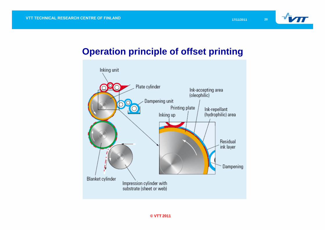
Operation principle of offset printing
Offset printing is an indirect printing method where ink is transferred from the printing plate onto the substrate via an intermediate blanket cylinder. The image and non-image areas of the plate are on the same level but they have different surface energies: the image areas are ink-receptive and non-image areas ink-repellent but water-accepting.Dampening unit applies first a thin film of dampening water onto the non-image areas after which inking unit applies a thin layer of ink onto the image areas. The surface chemistry difference and the dampening water layer prevent ink from spreading onto the non-image areas. The dampening water also cools down the printing unit. The ink layer is then transferred onto the blanket cylinder and further onto the substrate. After the last printing unit, the ink layer is dried via absorption, polymerization, oxidation, or evaporation. [1]
2217/11/2011
© VTT 2011
Offset plates
Offset printing plates are typically made of aluminium that is coated with a photopolymer layer. The photopolymer layer cross-links as it is exposed to UV radiation. The unexposed material can be then washed off with solvents. After development, the plate is protected and strengthened by gumming and baking. CTP plates are today popular since they eliminate the need of page films. However, these plates are more expensive but due to their sensitivity the exposure time and energy are greatly reduced. Nowadays, also thermal, chemistry-free, and process-less CTP plates are gaining popularity. These plates improve the print quality, eliminate several plate making steps, or offer energy and cost savings. [1,17,18]
17. Kull, S.; Timpe, H.-J.; Flugel, M.; Baumann, H., Red-hot and violet. Photopolymer systems at your service. In: 58th Annual Technical conference of TAGA, Vancouver, B.C., Canada, 2006. p. 153-168.
18. Ozcan, A.; Yenidogan, S.; Sesli, Y., The comparison of prints produced by CTP and conventional plate. In: 58th Annual Technical conference of TAGA, Vancouver, B.C., Canada, 2006. p. 534-541.
2317/11/2011
© VTT 2011
Offset printing
The print quality of offset printing depends on:the ink properties, dampening water properties, substrate properties,
printing conditions, ink-water balance, design of the inking and dampening units, as well as the plate and blanket properties.
The quality of the offset printing is difficult and complicated to control. The most important quality factor is the ink-water balance that controls the amount of waste and ink transfer. [1,19]Offset printing inks have high viscosity (40-100 Pa·s). This high viscosity prevents excessive ink penetration into the substrate. The thickness of the ink film is typically 0.5-1.5 µm. Dampening water consists mainly of water (95-98 %) and additives such as isopropanol (IPA). IPA decreases the surface tension of water to increase the spreading rate of dampening water onto the non-image areas. [1]
19. Savastano, D. 2007. The challenge of emulsification. Ink world 13(2007)8. p. 4.
2417/11/2011
© VTT 2011
Screen printing (flat bed and rotary)
Screen printing can be utilized at numerous applications such as printing textiles, advertisements, ceramics, curved substrates, and electronics. In addition, the range of suitable inks is large. On the other hand, the printing speed is low and often the print quality is also poor. [1,20]
20. Stephens, J., Screen printing in a digital age. Pira. UK. 2000. 84 p.
2517/11/2011
© VTT 2011
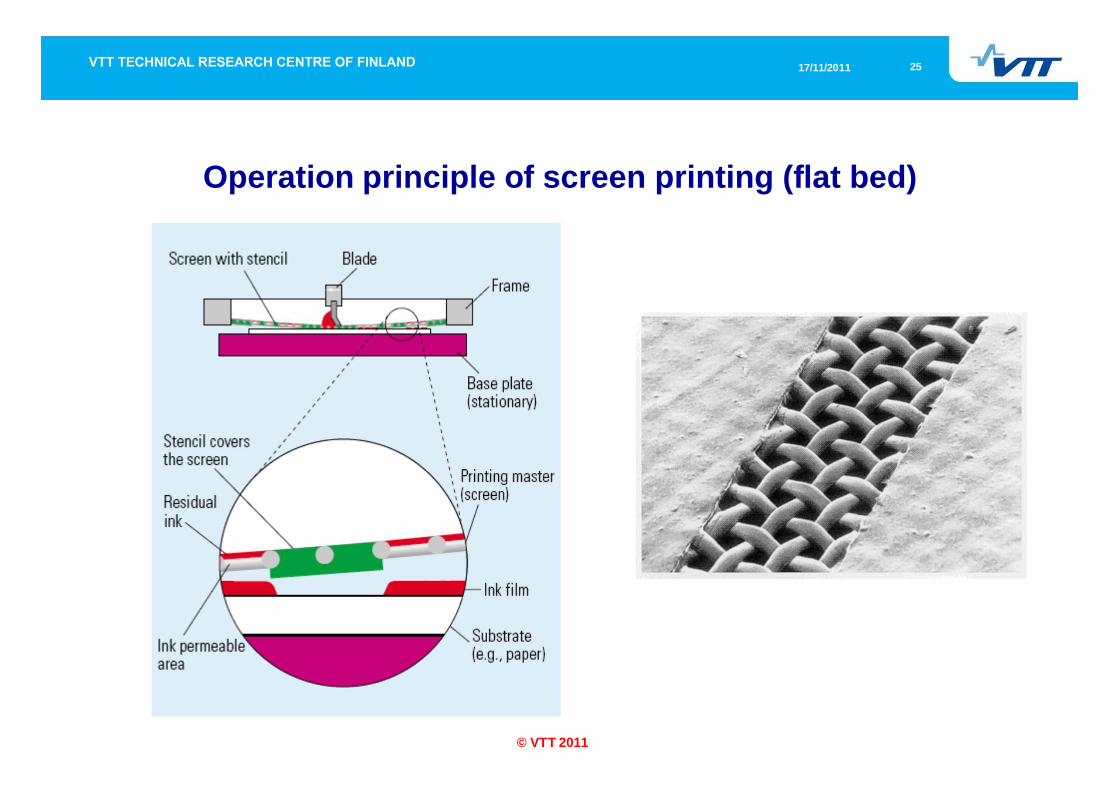
Operation principle of screen printing (flat bed)
2617/11/2011
© VTT 2011
Operation principle of screen printing (flat bed)
Screen printing is a push-through process where ink is pushed through a fine fabric (screen) made of plastic or metal threads. The non-image areas of the screen are covered with a stencil. The screen is flooded with ink which is pushed through the image areas of the screen onto the substrate by means of a squeegee.In order to tension the screen fabric, it is attached to a screen frame. The ink layer is then dried via evaporation, oxidation, or polymerization. [1,20]
2717/11/2011
© VTT 2011
Operation principle of screen printing (flat bed)
The thread count and the mesh thickness determine the openscreen area.This area should be large enough to pass though the pigments andfine enough to provide safe anchoring of the screen onto thesmallest parts of the stencil.The stencil that is typically made of photopolymer is placed on theopposite side of the screen than the squeegee to avoid its wear.The thickness of the ink layer depends on the thickness of thestencil that ranges from 12 to 100 µm. [1,20]
2817/11/2011
© VTT 2011
Operation principle of screen printing (flat bed)
The print quality is determined by the screen material, the finenessand thickness of the screen, as well as the degree of the open areaof the screen.The screen fineness is typically 90-120 fibers/cm.In order to produce high print quality, the screen fineness shouldbe approximately 3-4 times greater than the screen resolution(lines/cm).In addition, the ink, substrate, and squeegee properties and theprint conditions affect the print quality. [1,20]
2917/11/2011
© VTT 2011
Operation principle of screen printing (rotary)
3017/11/2011
© VTT 2011
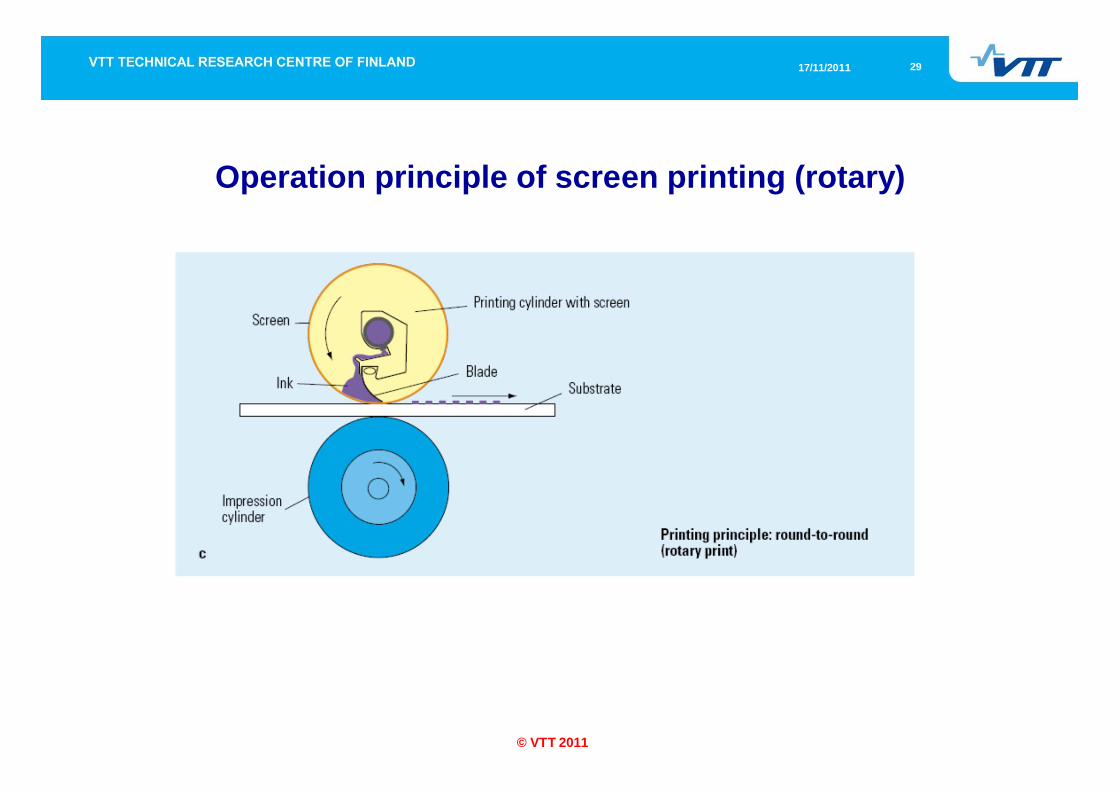
Operation principle of screen printing (rotary)
Rotary screen printing enables higher printing speeds and increases the print quality. The screen has a cylinder shape and the ink is also placed inside this cylinder. The stationary squeegee located inside the cylinder pushes ink through the screen apertures onto the substrate as the cylinder rotates. The ink choice depends on the application as well as on the substrate. The ink viscosity must match to the desired ink layer thickness and the fineness of the screen. Typically, the ink film is 8-30 µm thick. [1]
3117/11/2011
© VTT 2011
Comparison
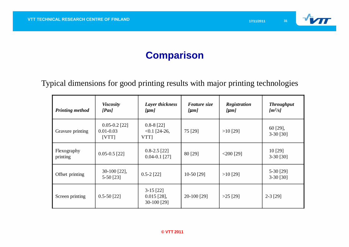
Typical dimensions for good printing results with major printing technologies
Printing methodViscosity[Pas]
Layer thickness[µm]
Feature size[µm]
Registration[µm]
Throughput[m2/s]
Gravure printing0.05-0.2 [22]
0.01-0.03[VTT]
0.8-8 [22]<0.1 [24-26,
VTT]75 [29] >10 [29] 60 [29],
3-30 [30]
Flexography printing 0.05-0.5 [22] 0.8-2.5 [22]
0.04-0.1 [27] 80 [29] <200 [29] 10 [29]3-30 [30]
Offset printing 30-100 [22],5-50 [23] 0.5-2 [22] 10-50 [29] >10 [29] 5-30 [29]
3-30 [30]
Screen printing 0.5-50 [22]3-15 [22]0.015 [28],30-100 [29]
20-100 [29] >25 [29] 2-3 [29]
3217/11/2011
© VTT 2011
References
Kipphan, H., Handbook of print media. Springer-Verlag, Heidelberg, Germany, 2001. 1207 p.Gravure Association of America, Gravure Process and Technology, Rochester NY, 2003.Rong, X.; Pekarovic, J.; Pekarovicova, A., Gravure printability from laser and electromechanically engraved cylinder, In: 11th International Printing and Graphics Arts Conference, Toronto, Canada, 2002. p. 151-154.Sjöblom, R.; Nordström, J.-E.P.; Erho, T.; Saari, J., Halftone rotogravure ink transfer determinations on LWC paper. In: 58th Appita Annual Conference, Canberra, Australia, 2004. p. 115-136.Hennig, G., Direct laser system for rotogravure printing. Gravure 15(2001)4. p. 58-61.Li, A., The Gravure Atom: An Evaluation of Cell Structure. Gravure 21(2007)3. p. 32-38.Kunz, W., Ink transfer in gravure process. In: 27th Annual Technical conference of TAGA, 1975. p. 151-176.Pekarovicova, A.; Pekarovic, J.; Serafano, J., Flexo printability of publication grades: technical challenges of publication flexography. In: 53rd Annual Technical Conference of TAGA, San Diego, USA, 2001. p. 98-110.Savastano, D., The flexo ink market. Ink world 83(2005)2. p. 48-52.Jones, K.; Kent, P.; Bingham, J.; Burgess, D., Anilox roll screen and volume: history, trends and proper selection. Flexo 32(2007)5. p. 18-23.Roffers, R. J., What you weren’t told about your anilox sleeve! Flexo 31(2006)10. p. 45-47.Hahn, L. M., Variables in printability and ink transfer in flexography. Ink Maker 81(2003)4. p. 46-50.Galton, D., Photopolymer plate characterization. In: 52th Annual Technical Conference of TAGA, Ashville, NC, USA, 2002. p. 109-127.Galton, D., Platemaking technologies and trends. Flexo, 32(2007)1. p. 44-48.
3317/11/2011
© VTT 2011
References
Cherry, J.; Claypole, T. C.; Gethin, D. T., Measurement of the ink release from the anilox roll. In: 58th Annual Technical Conference of TAGA, Vancouver, B.C., Canada, 2006. p. 395-408.Bould, D.C.; Hamblyn, S.M.; Claypole, T.C.; Bohan, M.F.J., The effect of process characteristics on image reproduction in flexographic printing. In: 33rd International research conference of IARIGAI, Leipzig, Germany, 2006. Kull, S.; Timpe, H.-J.; Flugel, M.; Baumann, H., Red-hot and violet. Photopolymer systems at your service. In: 58th Annual Technical conference of TAGA, Vancouver, B.C., Canada, 2006. p. 153-168.Ozcan, A.; Yenidogan, S.; Sesli, Y., The comparison of prints produced by CTP and conventional plate. In: 58th Annual Technical conference of TAGA, Vancouver, B.C., Canada, 2006. p. 534-541.Savastano, D. 2007. The challenge of emulsification. Ink world 13(2007)8. p. 4.Stephens, J., Screen printing in a digital age. Pira. UK. 2000. 84 p.Digital and screen printing association, Common printing processes: Principles of operation and applications, http://www.spauk.co.uk/VISITORS/Print%20Processes.pdf.Huebler, A.; Hahn, U.; Beier, W.; Lasch, N.; Fischer, T., High Volume Printing Technologies for the Production of Polymer Electronic Structures. In: 2nd International IEEE Conference on Polymers and Adhesives in Microelectronics and Photonics, Zalaegerzeg, Hungary, 2002. p. 172-176Blayo, A.; Pineaux, B., Printing Processes and their Potential for RFID Printing. In: Proceedings of the 2005 joint conference on Smart objects and ambient intelligence, Grenoble, France, 2005. p. 27-30.
3417/11/2011
© VTT 2011
ReferencesKawahara, T.; Doushita, K.; Tada, H., A large area patterned TiO2/SiO2 bilayer type photocatalyst prepared by gravure printing, Journal of sol-gel science and technology, 27(2003). p.301-307Maaninen, A.; Tuomikoski, M.; Kivimäki, L.; Kololuoma, T.; Välimäki, M.; Leinonen, M.; Känsäkoski, M., Roll to roll fabrication technologies for optoelectronic and electronic devices and sensors. In: Proceedings of SPIE, 5956, Warsaw, Poland, 2005. p.25-34.Bergsmann, M.; Kastner, F.; Bauer, G.; Domnick, R., Novel security feature made by thin film coating technique. In: 46th Annual technical conference proceedings of the society of the vacuum coaters, San Francisco, USA, 2003. p. 556-569Joyo Engineering/Crystec Technology Trading GmbH, Printing Machines for LCD Manufacturing, http://www.crystec.com/joyprie.htmJabbour, G.E.; Radspinner, R.; Peyghambarian, N., Screen Printing for the Fabrication of Organic Light-Emitting Devices. IEEE Journal on selected topics in quantum electronics, 7(2001)5. p. 769-773.Sirringhaus, H., Device physics and reliability of solution processed organic TFTs. Flexidis Training Workshop, Stuttgart, Germany, 2006.Schrödner, M.; Schultheis, K.; Stohn, R.; Schache H.; Blankenburg, L.; Roth, H., Reel-to-reel laser patterning and coating for the production of polymer electronic devices. In: Technologies for Polymer Electronics, Frankfurt, Germany, 2006.Kim J.Y.; Kim S.H., Lee H.-H; Ma W, Gong X.; Heeger A.J., New Architecture for High-Efficiency Polymer Photovoltaic Cells Using Solution-Based Titanium Oxide as an Optical Spacer. Advanced Materials 18(2006)5. p. 572-576.Kim J.Y.; Lee K.; Coates N.E.; Moses D.; Nguyen T.Q.; Dante M.; Heeger A.J., Efficient Tandem Polymer Solar Cells Fabricated by All-Solution Processing. Science 317(2007)5838. p.222-225. Lee K.; Kim J.Y.; Park S.H.; Kim S.H.; Cho S.; Heeger A.J., Air-Stable Polymer Electronic Devices. Advanced Materials 19(2007)18. p. 2446-2449.

3517/11/2011
© VTT 2011
VTT creates business from technology