Embed Size (px)
DESCRIPTION
Principles of Systems Engineering Introduction & Overview. Agenda. Definitions of system and systems engineer The role of a systems engineer Systems engineering vs. project management Systems engineering functions and processes Requirements Development and Management - PowerPoint PPT Presentation
Citation preview
Morgan State University • Systems Engineering Lecture 1
Principles of Systems Engineering
Introduction & Overview
Morgan State University • Systems Engineering Lecture 1 2
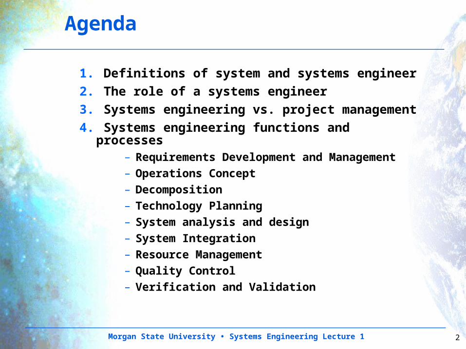
Agenda
1. Definitions of system and systems engineer
2. The role of a systems engineer
3. Systems engineering vs. project management
4. Systems engineering functions and processes
– Requirements Development and Management
– Operations Concept– Decomposition– Technology Planning– System analysis and design– System Integration– Resource Management– Quality Control– Verification and Validation
Morgan State University • Systems Engineering Lecture 1 3
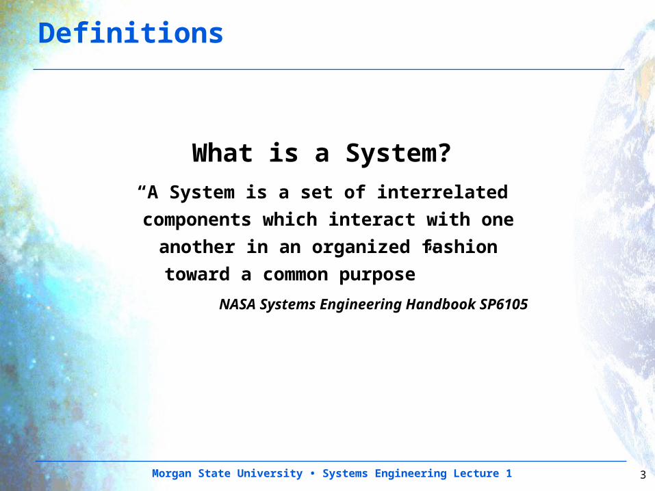
Definitions
What is a System?“A System is a set of interrelated
components which interact with one
another in an organized fashion
toward a common purpose”
NASA Systems Engineering Handbook SP6105
Morgan State University • Systems Engineering Lecture 1 4
Definitions (Continued)
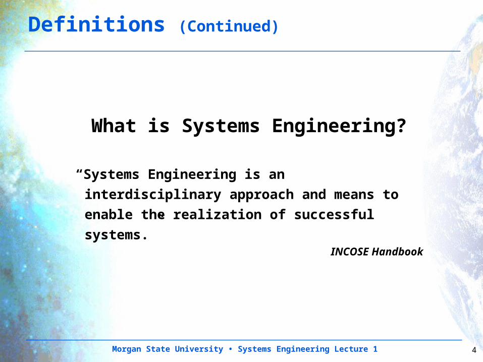
What is Systems Engineering?
“Systems Engineering is an interdisciplinary
approach and means to enable the
realization of successful systems.”INCOSE Handbook
Morgan State University • Systems Engineering Lecture 1 5
Definitions (Continued)
Another Definition
“Systems Engineering is a robust approach to the
design, creation, and operations of systems.”NASA Systems Engineering Handbook SP-6105
Morgan State University • Systems Engineering Lecture 1 6
Definitions (Continued)
In simple terms, the systems engineering approach consists of:
– Identification and quantification of system goals, – Creation of alternative system design concepts, – Performance of design trades, – Selection and implementation of the best design, – Verification that the design is properly built and
integrated, and – Post implementation assessment of how well the
system meets (or met) the goals
Morgan State University • Systems Engineering Lecture 1 7
Definitions (Continued)
“Engineering of Systems”
Anyone involved in engineering a system should exercise good systems engineering practices.
Morgan State University • Systems Engineering Lecture 1 8
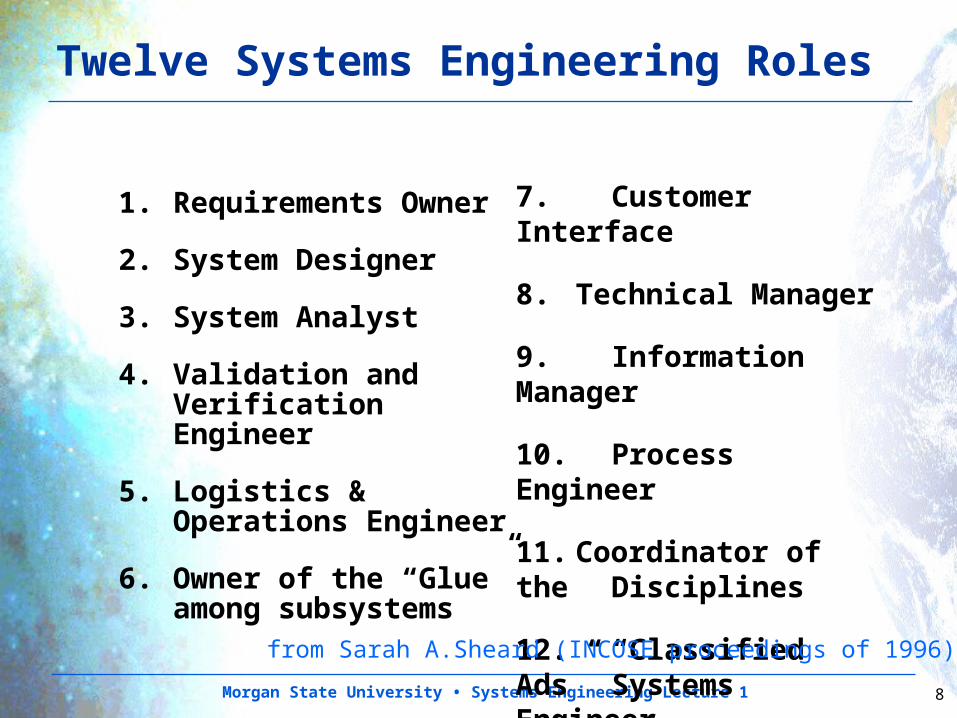
Twelve Systems Engineering Roles
1. Requirements Owner
2. System Designer
3. System Analyst
4. Validation and Verification Engineer
5. Logistics & Operations Engineer
6. Owner of the “Glue” among subsystems
7. Customer Interface
8. Technical Manager
9. Information Manager
10. Process Engineer
11. Coordinator of the Disciplines
12. “Classified Ads” Systems Engineer
from Sarah A.Sheard (INCOSE proceedings of 1996)
Morgan State University • Systems Engineering Lecture 1 9
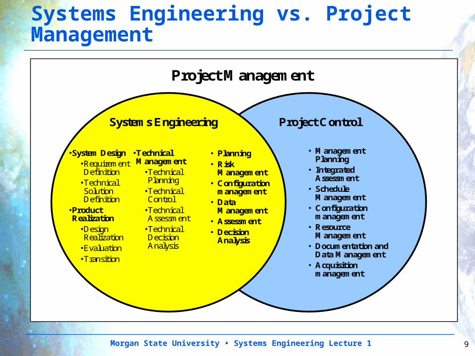
Systems Engineering Project Control
•System Design•Requirement Definition
•Technical Solution Definition
•Product Realization
•Design Realization
•Evaluation•Transition
•Technical Management
•Technical Planning
•Technical Control
•Technical Assessment
•Technical Decision Analysis
• Planning• Risk
Management• Configuration
management• Data
Management• Assessment• Decision
Analysis
• Management Planning
• Integrated Assessment
• Schedule Management
• Configuration management
• Resource Management
• Documentation and Data Management
• Acquisition management
Project Management
Systems Engineering vs. Project Management
Morgan State University • Systems Engineering Lecture 1 10
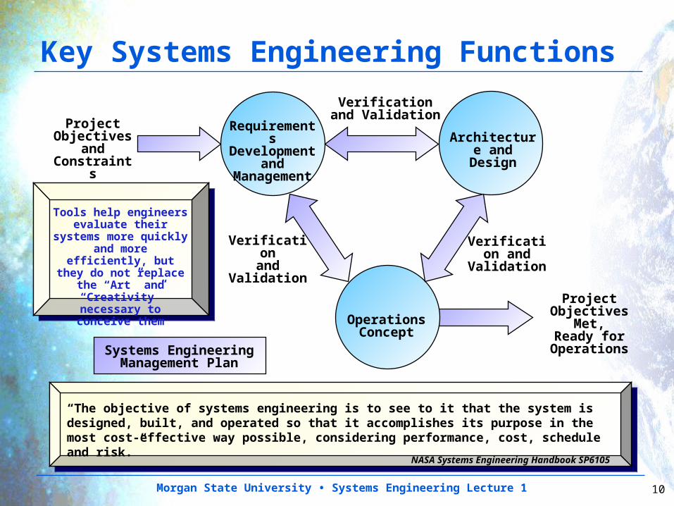
Key Systems Engineering Functions
Tools help engineers evaluate their
systems more quickly and more efficiently,
but they do not replace the “Art” and
“Creativity” necessary to
conceive them
“The objective of systems engineering is to see to it that the system is designed, built, and operated so that it accomplishes its purpose in the most cost-effective way possible, considering performance, cost, schedule and risk.”
NASA Systems Engineering Handbook SP6105
Project Objectives
and Constraint
s
Requirements
Development and
Management
Architecture and Design
Operations Concept
Verification and Validation
Verification
andValidation
Verification and
Validation
Systems Engineering Management Plan
Project Objectives
Met,Ready for
Operations
Morgan State University • Systems Engineering Lecture 1 11
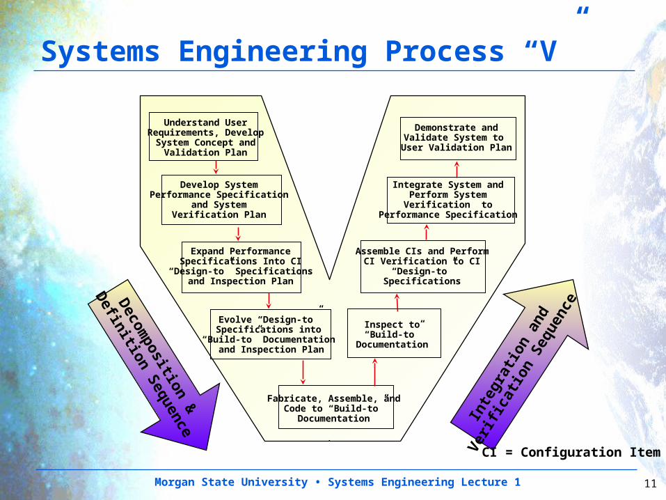
Decom
position
&
Defi
nitio
n S
equen
ceIn
tegra
tion
and
Ver
ifica
tion
Seq
uen
ce
Understand UserRequirements, Develop
System Concept andValidation Plan
Demonstrate andValidate System to User Validation Plan
Develop SystemPerformance Specification
and SystemVerification Plan
Expand PerformanceSpecifications Into CI
“Design-to” Specificationsand Inspection Plan
Evolve “Design-to”Specifications into
“Build-to” Documentation and Inspection Plan
Integrate System andPerform SystemVerification to
Performance Specification
Assemble CIs and PerformCI Verification to CI
“Design-to”Specifications
Inspect to“Build-to”
Documentation
Fabricate, Assemble, andCode to “Build-to”
Documentation
CI = Configuration Item
Systems Engineering Process “V”
Morgan State University • Systems Engineering Lecture 1 12
*Kevin Forsberg and Harold Mooz, "The Relationship of System Engineering to the Project Cycle," Proceedings of the First Annual Symposium of National Council on System Engineering (NCOSE), Chattanooga, Tennessee, Oct. 1991, pp 57 - 65.
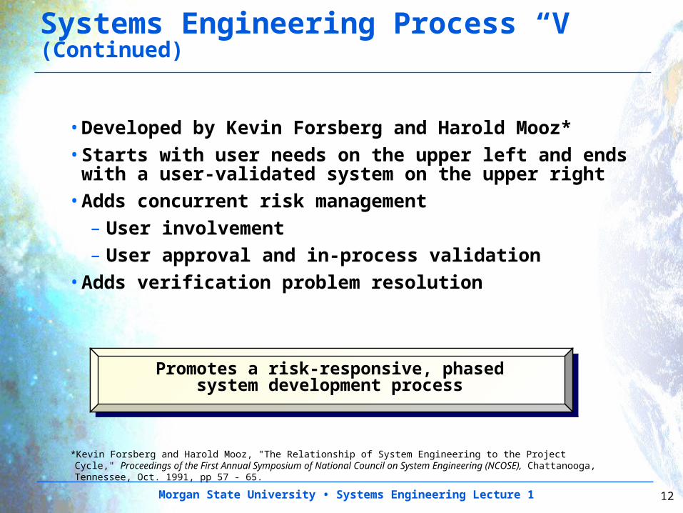
Systems Engineering Process “V” (Continued)
•Developed by Kevin Forsberg and Harold Mooz*•Starts with user needs on the upper left and ends with a user-validated system on the upper right
•Adds concurrent risk management– User involvement– User approval and in-process validation
•Adds verification problem resolution
Promotes a risk-responsive, phased system development process
Morgan State University • Systems Engineering Lecture 1 13
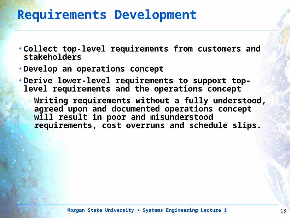
Requirements Development
•Collect top-level requirements from customers and stakeholders
•Develop an operations concept•Derive lower-level requirements to support top-level requirements and the operations concept– Writing requirements without a fully understood,
agreed upon and documented operations concept will result in poor and misunderstood requirements, cost overruns and schedule slips.
Morgan State University • Systems Engineering Lecture 1 14
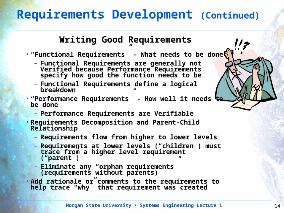
Writing Good Requirements
• “Functional Requirements” - What needs to be done– Functional Requirements are generally not
Verified because Performance Requirements specify how good the function needs to be
– Functional Requirements define a logical breakdown
• “Performance Requirements” - How well it needs to be done– Performance Requirements are Verifiable
• Requirements Decomposition and Parent-Child Relationship– Requirements flow from higher to lower levels– Requirements at lower levels (“children”) must
trace from a higher level requirement (“parent”)– Eliminate any “orphan requirements”
(requirements without parents) • Add rationale or comments to the requirements to
help trace “why” that requirement was created
Requirements Development (Continued)
Morgan State University • Systems Engineering Lecture 1 15
Requirements Development (Continued)
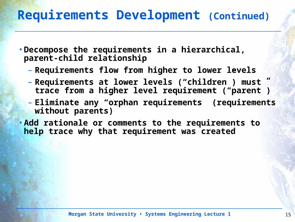
•Decompose the requirements in a hierarchical, parent-child relationship– Requirements flow from higher to lower levels– Requirements at lower levels (“children”) must
trace from a higher level requirement (“parent”)– Eliminate any “orphan requirements” (requirements
without parents) •Add rationale or comments to the requirements to help trace why that requirement was created
Morgan State University • Systems Engineering Lecture 1 16
Requirements Development (Continued)
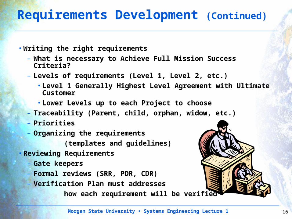
• Writing the right requirements– What is necessary to Achieve Full Mission Success Criteria?– Levels of requirements (Level 1, Level 2, etc.)
• Level 1 Generally Highest Level Agreement with Ultimate Customer
• Lower Levels up to each Project to choose– Traceability (Parent, child, orphan, widow, etc.)– Priorities– Organizing the requirements
(templates and guidelines) • Reviewing Requirements
– Gate keepers– Formal reviews (SRR, PDR, CDR)– Verification Plan must addresses
how each requirement will be verified
Morgan State University • Systems Engineering Lecture 1 17
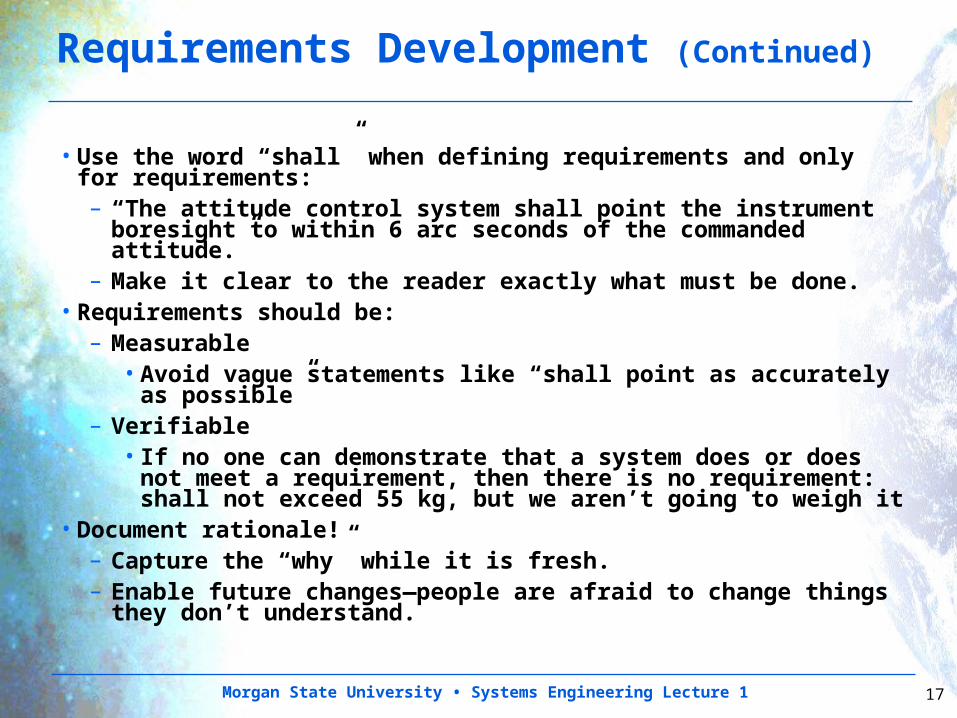
Requirements Development (Continued)
• Use the word “shall” when defining requirements and only for requirements:– “The attitude control system shall point the instrument
boresight to within 6 arc seconds of the commanded attitude.”
– Make it clear to the reader exactly what must be done.• Requirements should be:
– Measurable•Avoid vague statements like “shall point as accurately
as possible”– Verifiable
• If no one can demonstrate that a system does or does not meet a requirement, then there is no requirement: shall not exceed 55 kg, but we aren’t going to weigh it
• Document rationale!– Capture the “why” while it is fresh.– Enable future changes—people are afraid to change
things they don’t understand.
Morgan State University • Systems Engineering Lecture 1 18
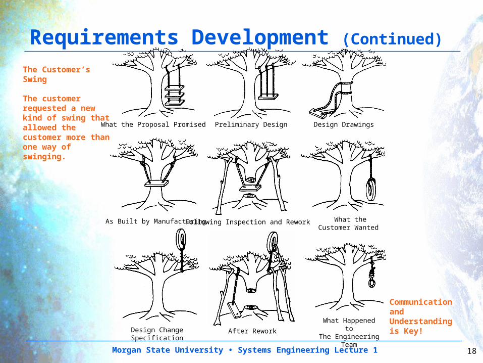
What the Proposal Promised Preliminary Design Design Drawings
As Built by ManufacturingFollowing Inspection and Rework What the Customer Wanted
Design Change Specification
After Rework
What Happened toThe Engineering
Team
The Customer’s Swing
The customer requested a new kind of swing that allowed the customer more than one way of swinging.
Communication and Understanding is Key!
Requirements Development (Continued)
Morgan State University • Systems Engineering Lecture 1 19
Requirements Management
•Collect top-level requirements from customers and stakeholders
•Develop operations concept•Derive lower-level requirements to support top-level requirements and the operations concept
•Choose an appropriate tool to store and manage the requirements– This can range from an Excel spreadsheet for
simple projects to sophisticated tools such as DOORS, Team Center, CORE, etc. for more complex projects
•Baseline the requirements at a System Requirements Review (SRR)– “Baseline” means requirements are signed off
and put under configuration control•Control any future changes to requirements through a configuration management process
Morgan State University • Systems Engineering Lecture 1 20
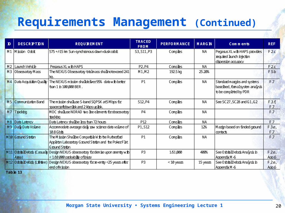
ID DESCRIPTION REQUIREMENTTRACED FROM
PERFORMANCE MARGIN Comments REF
M1 Mission Orbit 575 +/-15 km Sun-synchronous dawn-dusk orbit S3, S11, P3 Complies NA Pegasus XL with HAPS provides required launch injection dispersion accuracy
F.2.c
M2 Launch Vehicle Pegasus XL with HAPS P2, P4 Complies NA F.2.cM3 Observatory Mass The NEXUS Observatory total mass shall not exceed 241
kg. M1, M2 192.5 kg 25.20% F.5.b
M4 Data Acquisition Quality The NEXUS mission shall deliver 95% data with better than 1 in 100,000 BER.
P1 Complies NA Standard margins and systems baselined, formal system analysis to be completed by PDR
F.7
M5 Communication Band The mission shall use S-band SQPSK at 5 Mbps for spacecraft downlink and 2 kbps uplink.
S12, P4 Complies NA See SC27, SC28 and G1, G2 F.3.f,F.7
M7 Tracking MOC shall use NORAD two line elements for observatory tracking
P4 Complies NA F.7
M8 Data Latency Data Latency shall be less than 72 hours P12 Complies NA F.7M9 Daily Data Volume Accommodate average daily raw science data volume of
10.8 Gbits P1, S12 Complies 12% Marign based on funded ground
contacts F.3.e,
F.7M10 Ground Station The Mission Shall be Compatible With the Rutherford
Appleton Laboratory Ground Station and the Poker Flat Ground Station
P1 Complies NA F.7
M11 Orbital Debris (Casualty Area)
Design NEXUS observatory for demise upon reentry with < 1/10,000 probability of injury
P3 1/51,000 400% See Orbital Debris Analysis in Appendix M-6
F.2.e,App.6
M12 Orbital Debris (Lifetime) Design NEXUS observatory for re-entry <25 years after end of mission
P3 < 10 years 15 years See Orbital Debris Analysis in Appendix M-6
F.2.e,App.6
Table 13
Requirements Management (Continued)
Morgan State University • Systems Engineering Lecture 1 21
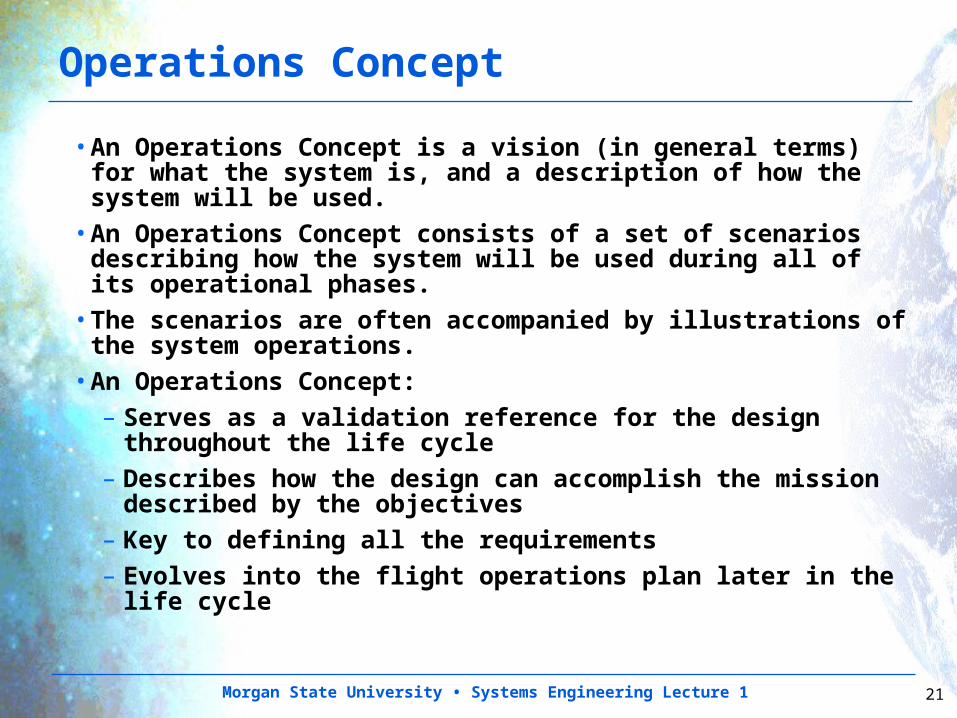
•An Operations Concept is a vision (in general terms) for what the system is, and a description of how the system will be used.
•An Operations Concept consists of a set of scenarios describing how the system will be used during all of its operational phases.
•The scenarios are often accompanied by illustrations of the system operations.
•An Operations Concept:– Serves as a validation reference for the design
throughout the life cycle– Describes how the design can accomplish the mission
described by the objectives– Key to defining all the requirements– Evolves into the flight operations plan later in the life
cycle
Operations Concept
Morgan State University • Systems Engineering Lecture 1 22
Operations Concept (Continued)
•Stakeholders participate in the development of the Operations Concept
•Trade studies and analyses are used to demonstrate that the operations concept will meet the mission requirements within cost and schedule constraints
Morgan State University • Systems Engineering Lecture 1 23
• Considerations for developing an Operations Concept for a Space Mission:– Allocation of functions between ground segment and flight
segment– Mission operational modes and configurations– Time ordered sequence of mission activities– Identification of facilities, equipment and procedures needed
to ensure the safe development and operation of the system– Operations team size, staffing and extent of automation– Ground segment functions– Contingency concepts– Ground test configurations necessary to accomplish
verification including GSE, BTE, simulators and non-flight articles such as ETU’s
– Description of functions that cut across various subsystems • Observation strategy• Date collection, storage and downlink• Ground station utilization• Mission orbit maintenance and maneuvers• Power and battery management
Operations Concept (Continued)
Morgan State University • Systems Engineering Lecture 1 24
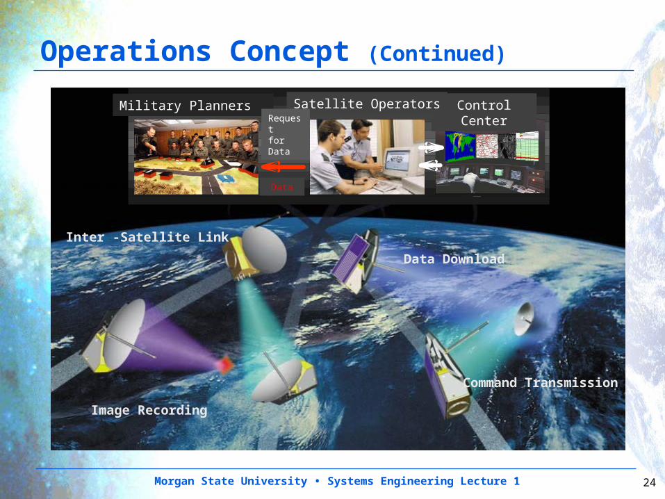
Image Recording
Inter -Satellite Link
MILITÄRISCHER NUTZER
Dossier
Auftrag
NUTZER-BODENSEGMENT
SATELLITEN-BODENSEGMENT
Command Transmission
Data Download
Operations Concept (Continued)
Control CenterSatellite OperatorsMilitary Planners Request for Data
Data
Morgan State University • Systems Engineering Lecture 1 25
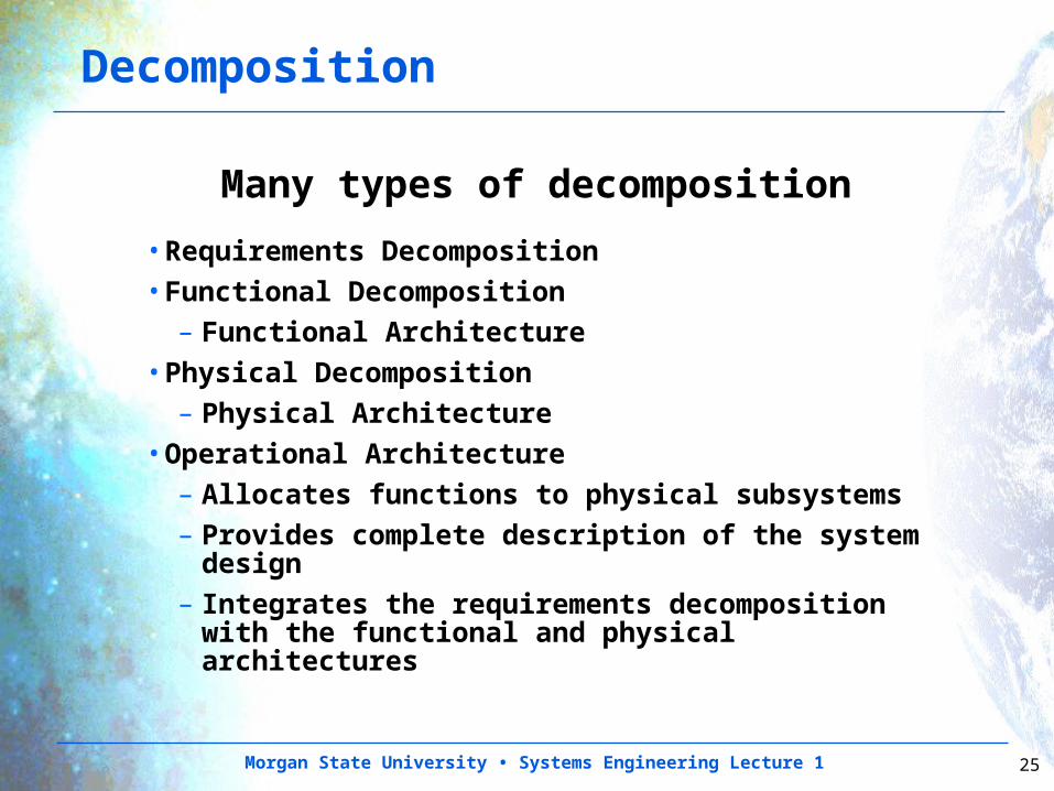
Decomposition
Many types of decomposition
•Requirements Decomposition•Functional Decomposition
– Functional Architecture•Physical Decomposition
– Physical Architecture•Operational Architecture
– Allocates functions to physical subsystems– Provides complete description of the
system design– Integrates the requirements
decomposition with the functional and physical architectures
Morgan State University • Systems Engineering Lecture 1 26
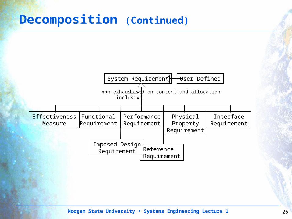
System Requirement
FunctionalRequirement
PerformanceRequirement
PhysicalProperty
Requirement
Imposed DesignRequirement Reference
Requirement
InterfaceRequirement
based on content and allocation
EffectivenessMeasure
User Defined
non-exhaustiveinclusive
Decomposition (Continued)
Morgan State University • Systems Engineering Lecture 1 27
Technology Planning
•Projects are sometimes initiated with known technology shortfalls– Technology “Pull”
•Often there are areas for which new technology will result in substantial product improvement– Technology “Push”
•Technology development can be done in parallel with the project evolution and inserted as late as the PDR
•Risk mitigation requires a parallel approach that is not dependent on the development of new technology
•The technology development activity should be managed as a critical activity
Morgan State University • Systems Engineering Lecture 1 28
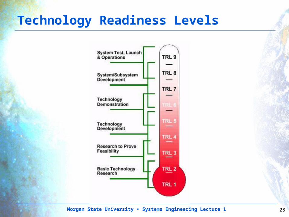
Technology Readiness Levels
Morgan State University • Systems Engineering Lecture 1 29
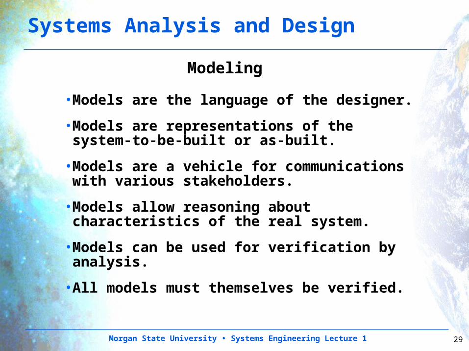
•Models are the language of the designer.
•Models are representations of the system-to-be-built or as-built.
•Models are a vehicle for communications with various stakeholders.
•Models allow reasoning about characteristics of the real system.
•Models can be used for verification by analysis.
•All models must themselves be verified.
Systems Analysis and Design
Modeling
Morgan State University • Systems Engineering Lecture 1 30
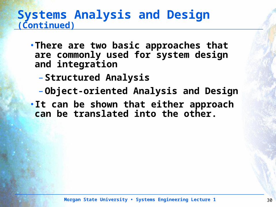
Systems Analysis and Design (Continued)
•There are two basic approaches that are commonly used for system design and integration– Structured Analysis– Object-oriented Analysis and Design
•It can be shown that either approach can be translated into the other.
Morgan State University • Systems Engineering Lecture 1 31
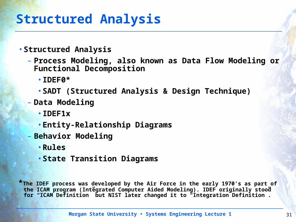
Structured Analysis
•Structured Analysis– Process Modeling, also known as Data Flow Modeling
or Functional Decomposition•IDEF0*•SADT (Structured Analysis & Design Technique)
– Data Modeling•IDEF1x•Entity-Relationship Diagrams
– Behavior Modeling•Rules •State Transition Diagrams
*The IDEF process was developed by the Air Force in the early 1970’s as part of the ICAM program (Integrated Computer Aided Modeling). IDEF originally stood for “ICAM Definition” but NIST later changed it to “Integration Definition”.
Morgan State University • Systems Engineering Lecture 1 32
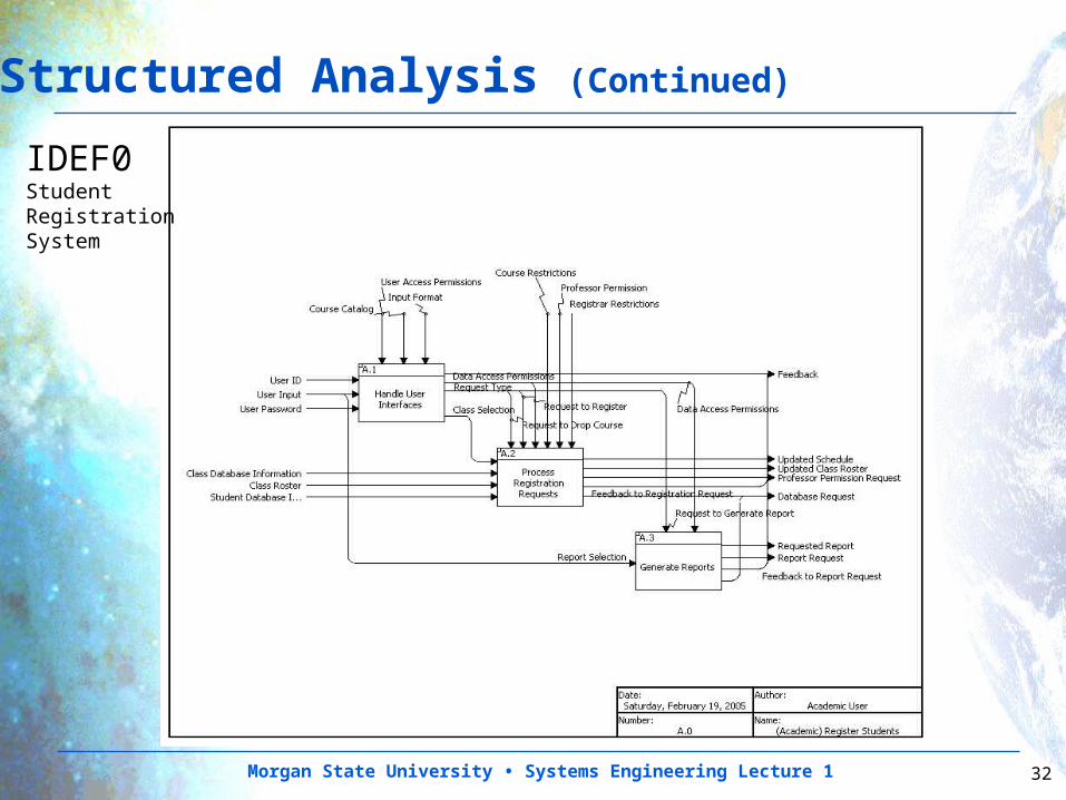
Structured Analysis (Continued)
IDEF0StudentRegistration System
Morgan State University • Systems Engineering Lecture 1 33
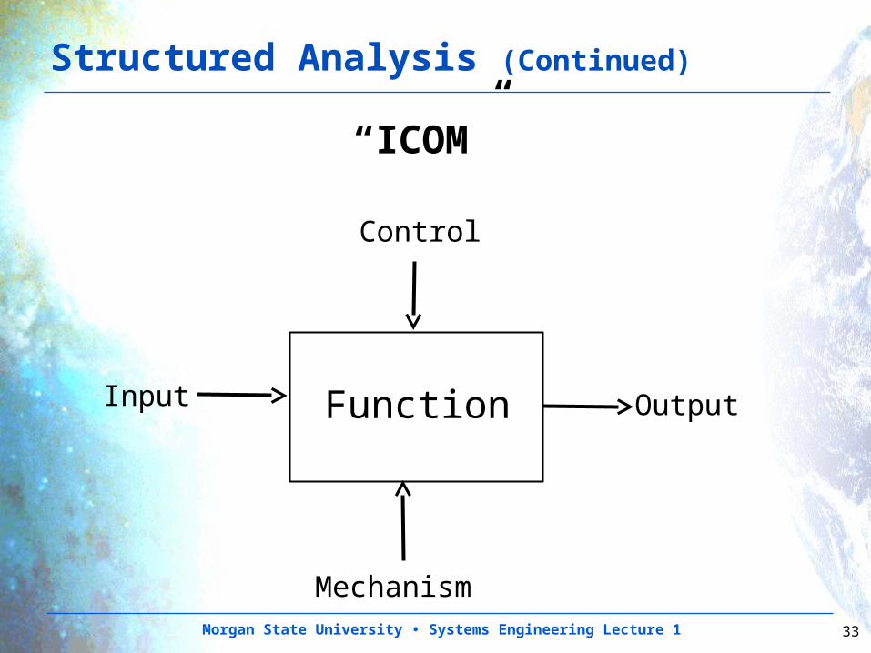
Structured Analysis (Continued)
“ICOM”
Input Output
Control
Mechanism
Function
Morgan State University • Systems Engineering Lecture 1 34
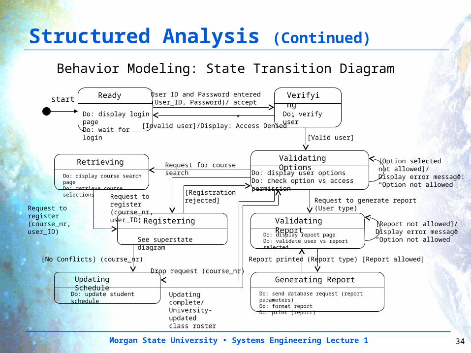
Ready Verifying
Do: verify user
[Valid user]
[Invalid user]/Display:”Access Denied”
Validating Options
Do: display user options Do: check option vs access permission
User ID and Password entered(User_ID, Password)/ accept
[Option selected not allowed]/Display error message: “Option not allowed”
Validating ReportRegistering
See superstate diagram
Request for course search
Do: display login pageDo: wait for login
Retrieving
Do: display course search pageDo: retrieve course selections
Request to register (course_nr, user_ID)
Request to register (course_nr, user_ID)
Request to generate report (User type)
Do: display report page Do: validate user vs report selected
[Report not allowed]/Display error message “Option not allowed”
(Report type) [Report allowed]
start
Generating Report
Do: send database request (report parameters)Do: format reportDo: print (report)
Updating Schedule
Do: update student schedule
[No Conflicts] (course_nr)
Drop request (course_nr)
[Registration rejected]
Updating complete/University-updated class roster
Report printed
Behavior Modeling: State Transition Diagram
Structured Analysis (Continued)
Morgan State University • Systems Engineering Lecture 1 35
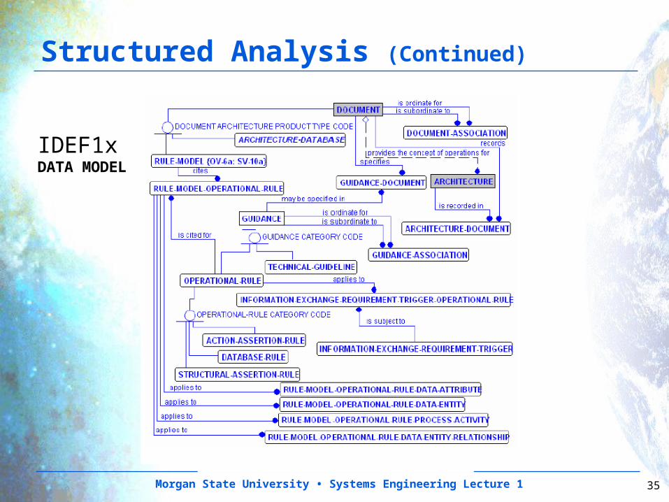
Structured Analysis (Continued)
IDEF1xDATA MODEL
Morgan State University • Systems Engineering Lecture 1 36
Object-Oriented Analysis and Design
•Object-Oriented Analysis and Design– The concept of “object” or “object class” is the
result of a long history of software engineering design.•From a programming viewpoint, an object is a collection of specialized data packaged with the functions (operations and methods) which are needed specifically by that specialized data.
•From a systems design viewpoint, an object is a system or component which maintains its own information and is able to perform some specific functions.
– Developed more recently for software engineering, object- oriented design is now migrating to systems engineering.
– Object-oriented design defines the relationships between object classes and the behavior of the classes.
Morgan State University • Systems Engineering Lecture 1 37
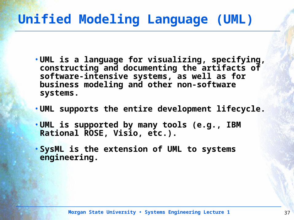
Unified Modeling Language (UML)
•UML is a language for visualizing, specifying, constructing and documenting the artifacts of software-intensive systems, as well as for business modeling and other non-software systems.
•UML supports the entire development lifecycle.
•UML is supported by many tools (e.g., IBM Rational ROSE, Visio, etc.).
•SysML is the extension of UML to systems engineering.
Morgan State University • Systems Engineering Lecture 1 38
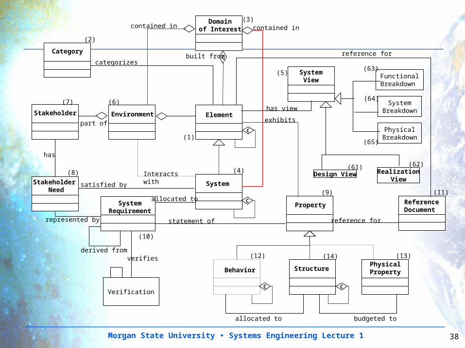
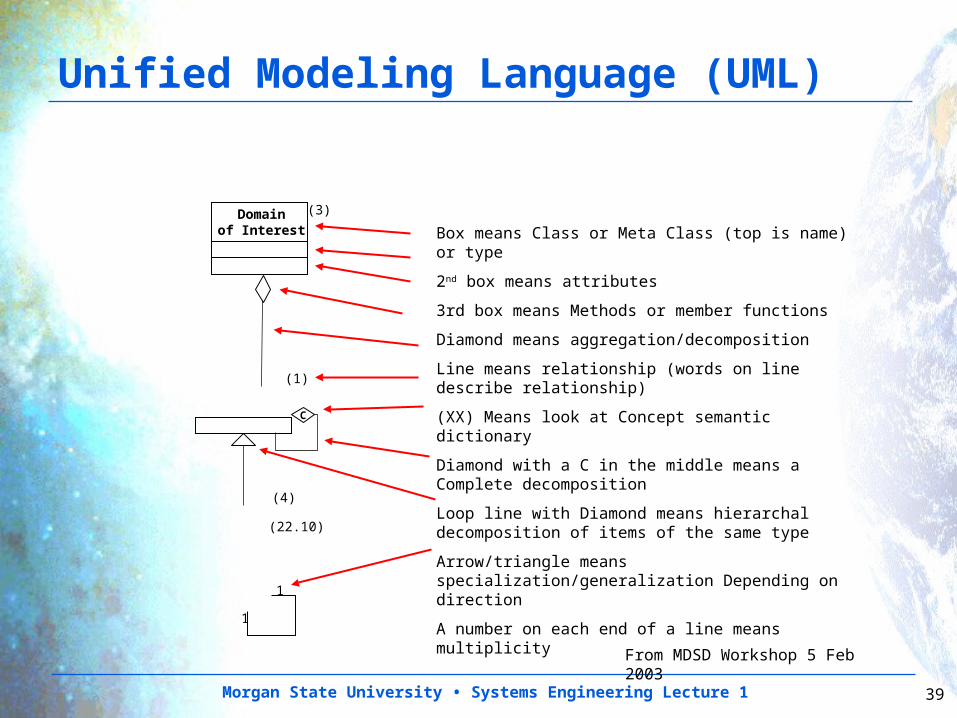
Domainof Interest
Element
System
Property
StructurePhysicalProperty
Environment
C
C
SystemRequirement
statement of
Interacts with
exhibits
allocated to
Stakeholder Need
Stakeholder
satisfied by
represented by
has
allocated to budgeted to
SystemView
has view
(1)
(3)
(5)
(4)
(6)(7)
(8)
derived from
(9)
(10)
Behavior
C
(12) (14) (13)
ReferenceDocument
(11)
reference for
categorizes
Category
(2)
reference for
Verification
verifies
contained in contained in
C
Cbuilt from
part of
Design View(61)
RealizationView
(62)
FunctionalBreakdown
SystemBreakdown
PhysicalBreakdown
(65)
(64)
(63)
Morgan State University • Systems Engineering Lecture 1 39
Domainof Interest
(1)
(3)
C
(4)
(22.10)
Box means Class or Meta Class (top is name) or type
2nd box means attributes
3rd box means Methods or member functions
Diamond means aggregation/decomposition
Line means relationship (words on line describe relationship)
(XX) Means look at Concept semantic dictionary
Diamond with a C in the middle means a Complete decomposition
Loop line with Diamond means hierarchal decomposition of items of the same type
Arrow/triangle means specialization/generalization Depending on direction
A number on each end of a line means multiplicity1
1
From MDSD Workshop 5 Feb 2003
Unified Modeling Language (UML)
Morgan State University • Systems Engineering Lecture 1 40
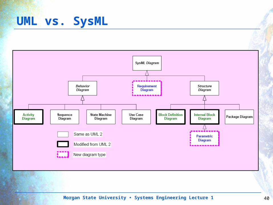
UML vs. SysML
Morgan State University • Systems Engineering Lecture 1 41
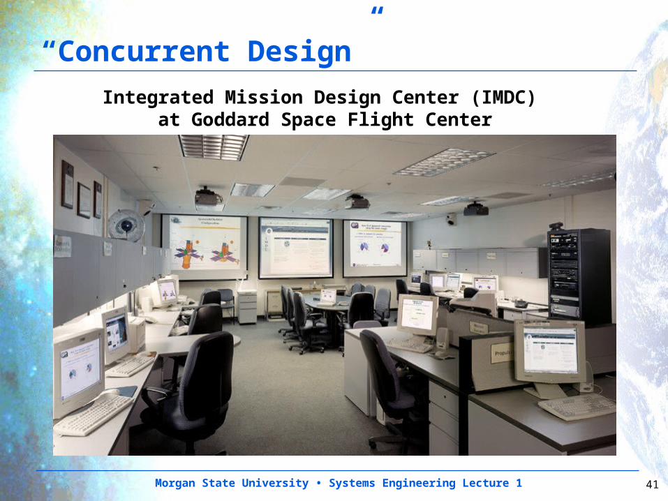
“Concurrent Design”
Integrated Mission Design Center (IMDC) at Goddard Space Flight Center
Morgan State University • Systems Engineering Lecture 1 42
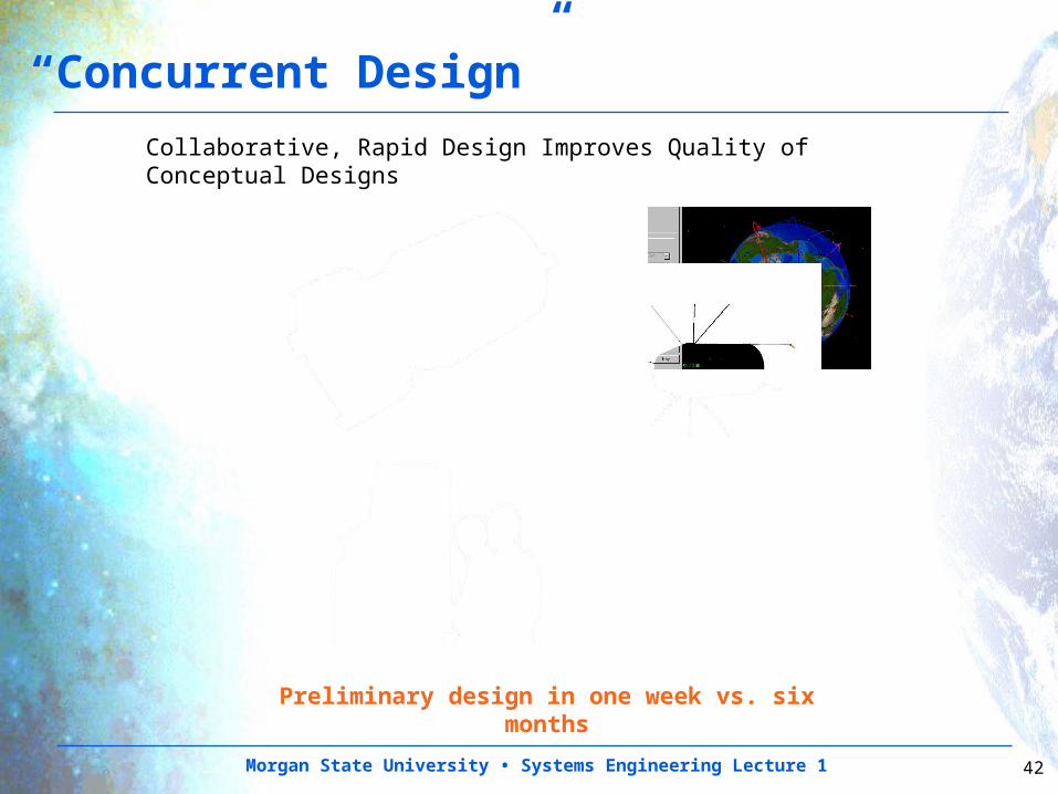
“Concurrent Design”
Collaborative, Rapid Design Improves Quality of Conceptual Designs
Preliminary design in one week vs. six months
Morgan State University • Systems Engineering Lecture 1 43
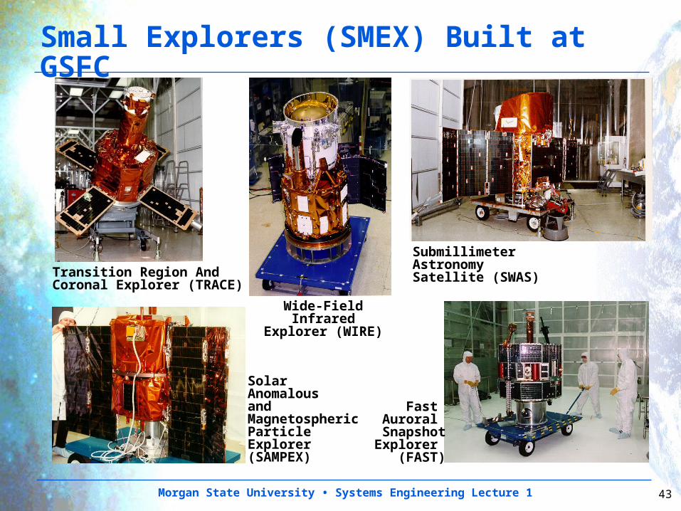
Small Explorers (SMEX) Built at GSFC
Wide-Field InfraredExplorer (WIRE)
Transition Region And Coronal Explorer (TRACE)
Submillimeter Astronomy Satellite (SWAS)
Fast Auroral
SnapshotExplorer
(FAST)
SolarAnomalousand MagnetosphericParticle Explorer(SAMPEX)
Morgan State University • Systems Engineering Lecture 1 44
System Integration
•Integration is the process of assembling the system from components.
•Integration begins with the elementary pieces or configuration items (CI’s) of the system.
•After each CI is tested, components comprising multiple CI’s are tested.
•This process continues until the entire system is assembled and tested.
•Interface Specifications and Interface Control are critical to a successful system integration.
Morgan State University • Systems Engineering Lecture 1 45
Work and Resource Management
•A Work Breakdown Structure (WBS) is a hierarchical breakdown of the work necessary to complete a project.
•The WBS should be a product-based, hierarchical division of deliverable items and associated services.
•The WBS should contain the Product Breakdown Structure (PBS).
•At the lowest level are products such as hardware items, software items, and information items (documents, databases, etc.) for which there is a cognizant engineer or manager.
•A project WBS should be carried down to the cost account level appropriate to the risks to be managed.
Morgan State University • Systems Engineering Lecture 1 46
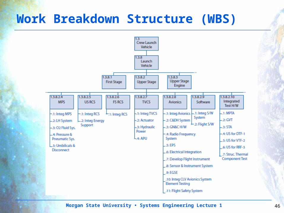
Work Breakdown Structure (WBS)
Morgan State University • Systems Engineering Lecture 1 47
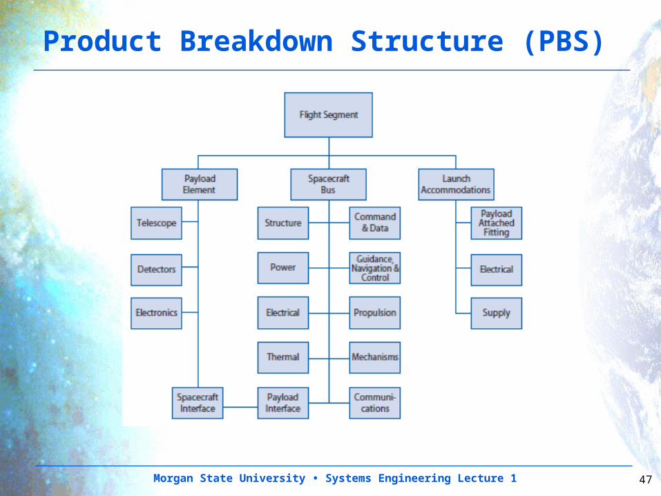
Product Breakdown Structure (PBS)
Morgan State University • Systems Engineering Lecture 1 48
Technical Resource Management
•Critical mission resources shall be identified, allocated and managed
•Acceptable resource margins shall be established•A margin management philosophy shall be set up based on design maturity and time– Required margins are reduced as the project matures– Margins are assessed based on the fidelity of the
estimate•Care must be taken that margins are not added to margins
– Stacked margins that do occur simultaneously in real life
– Lead systems engineer holds the overall system margins– Subsystem engineers must be allowed to hold some
margin in order to meet their design requirements– This hierarchy of margins must be taken into account so
that the overall system margins do not drive the design and the cost
Morgan State University • Systems Engineering Lecture 1 49
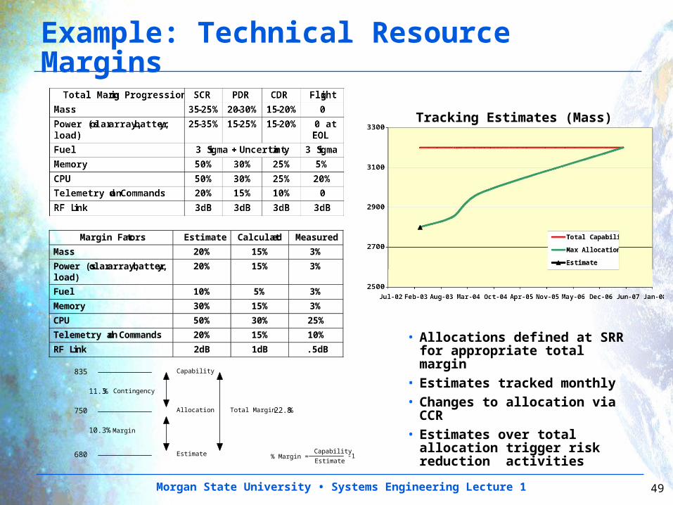
Example: Technical Resource Margins
Margin Factors Estimate Calculated Measured
Mass 20% 15% 3%
Power (solar array, battery, load)
20% 15% 3%
Fuel 10% 5% 3%
Memory 30% 15% 3%
CPU 50% 30% 25%
Telemetry and Commands 20% 15% 10%
RF Link 2dB 1dB .5dB
Estimate
Allocation
Capability
Margin
Contingency
Total Margin
835
750
680
10.3%
11.3%
22.8%
% Margin =Capability
Estimate-1
Tracking Estimates (Mass)
• Allocations defined at SRR for appropriate total margin
• Estimates tracked monthly• Changes to allocation via
CCR• Estimates over total
allocation trigger risk reduction activities
Morgan State University • Systems Engineering Lecture 1 50
Specialty Engineering
• Specialty engineers support the systems engineering process by applying specific knowledge and analytic methods from a variety of engineering specialty disciplines to ensure that the resulting system is actually able to perform its mission in its operational environment.
• For space systems these specialty areas often include:
– Quality Assurance
– Reliability
– Maintainability
– Producibility
– Logistics
– Safety
– Environment (e.g., radiation, atomic oxygen, atmospheric density, etc.)
– Contamination
– Parts Engineering
Morgan State University • Systems Engineering Lecture 1 51
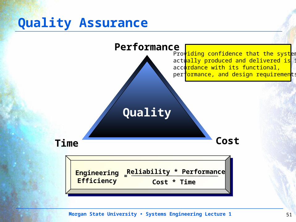
Quality
Performance
CostTime
EngineeringEfficiency
= Reliability * Performance
Cost * Time
Quality Assurance
Providing confidence that the system actually produced and delivered is in accordance with its functional, performance, and design requirements.
Morgan State University • Systems Engineering Lecture 1 52
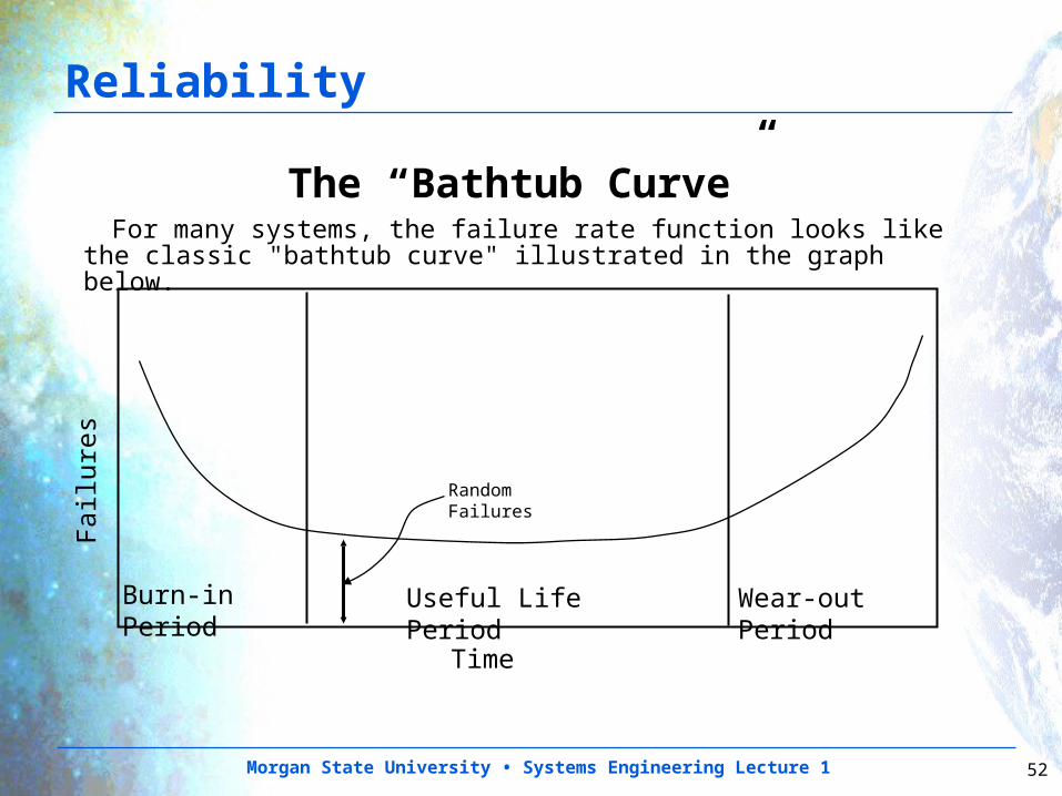
Reliability
The “Bathtub Curve” For many systems, the failure rate function looks like the
classic "bathtub curve" illustrated in the graph below.
Burn-in Period Useful Life Period Wear-out Period
Fai
lure
s
Time
Random Failures
Morgan State University • Systems Engineering Lecture 1 53
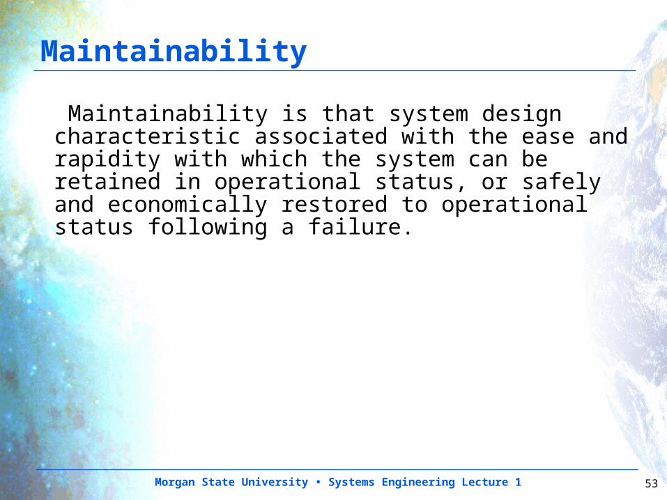
Maintainability
Maintainability is that system design characteristic associated with the ease and rapidity with which the system can be retained in operational status, or safely and economically restored to operational status following a failure.
Morgan State University • Systems Engineering Lecture 1 54
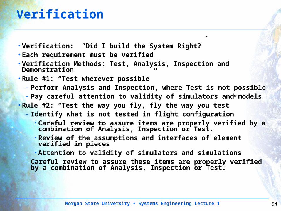
Verification
•Verification: “Did I build the System Right?”•Each requirement must be verified•Verification Methods: Test, Analysis, Inspection and Demonstration
•Rule #1: “Test wherever possible”– Perform Analysis and Inspection, where Test is not
possible– Pay careful attention to validity of simulators and models
•Rule #2: “Test the way you fly, fly the way you test”– Identify what is not tested in flight configuration
•Careful review to assure items are properly verified by a combination of Analysis, Inspection or Test.
•Review of the assumptions and interfaces of element verified in pieces
•Attention to validity of simulators and simulations– Careful review to assure these items are properly verified
by a combination of Analysis, Inspection or Test.
Morgan State University • Systems Engineering Lecture 1 55
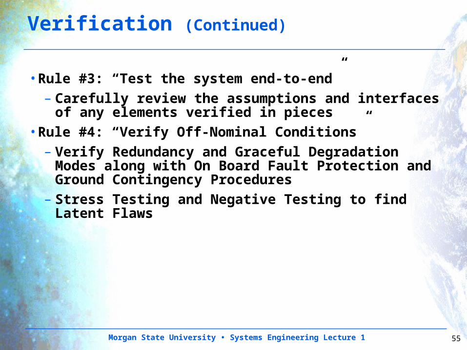
•Rule #3: “Test the system end-to-end”– Carefully review the assumptions and interfaces
of any elements verified in pieces•Rule #4: “Verify Off-Nominal Conditions”
– Verify Redundancy and Graceful Degradation Modes along with On Board Fault Protection and Ground Contingency Procedures
– Stress Testing and Negative Testing to find Latent Flaws
Verification (Continued)
Morgan State University • Systems Engineering Lecture 1 56
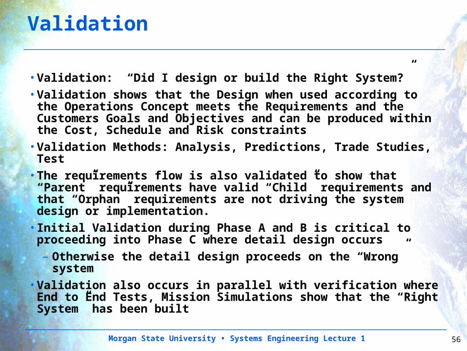
Validation
•Validation: “Did I design or build the Right System?”•Validation shows that the Design when used according to the Operations Concept meets the Requirements and the Customers Goals and Objectives and can be produced within the Cost, Schedule and Risk constraints
•Validation Methods: Analysis, Predictions, Trade Studies, Test
•The requirements flow is also validated to show that “Parent” requirements have valid “Child” requirements and that “Orphan” requirements are not driving the system design or implementation.
•Initial Validation during Phase A and B is critical to proceeding into Phase C where detail design occurs– Otherwise the detail design proceeds on the “Wrong”
system•Validation also occurs in parallel with verification where End to End Tests, Mission Simulations show that the “Right System” has been built
Morgan State University • Systems Engineering Lecture 1 57
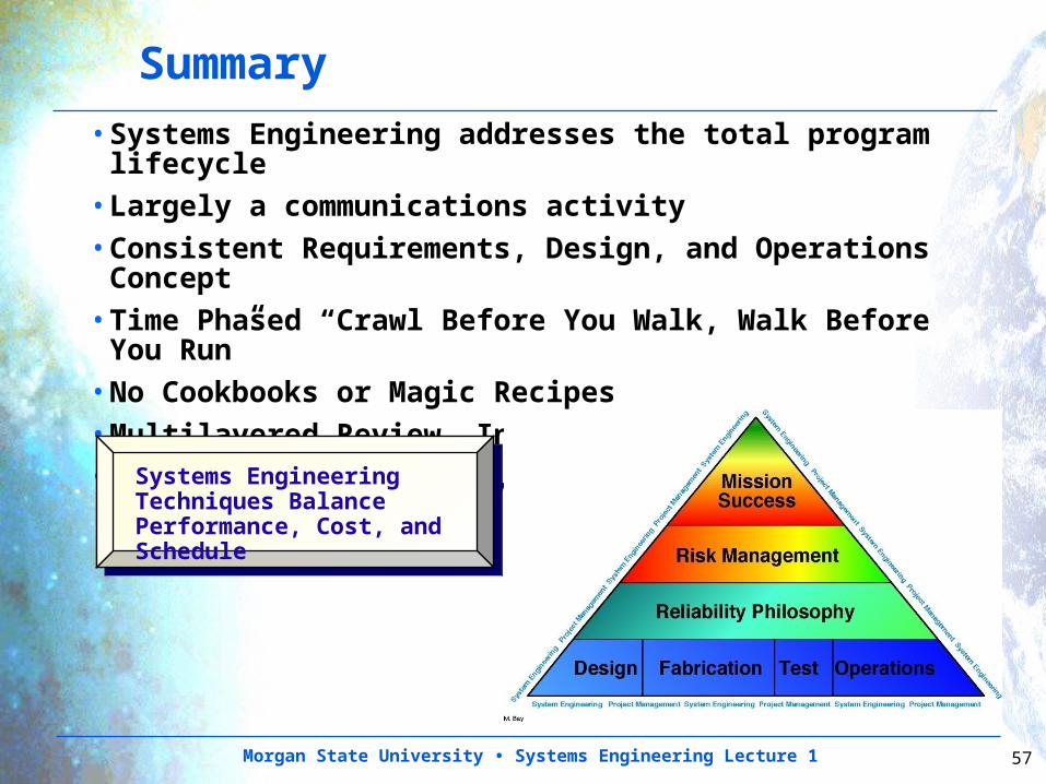
Summary•Systems Engineering addresses the total program lifecycle
•Largely a communications activity•Consistent Requirements, Design, and Operations Concept
•Time Phased “Crawl Before You Walk, Walk Before You Run”
•No Cookbooks or Magic Recipes•Multilayered Review, Inspection and Test Process•It is the Project Team, the People, that makes projects successful
Systems Engineering Techniques Balance Performance, Cost, and Schedule
Morgan State University • Systems Engineering Lecture 1 58
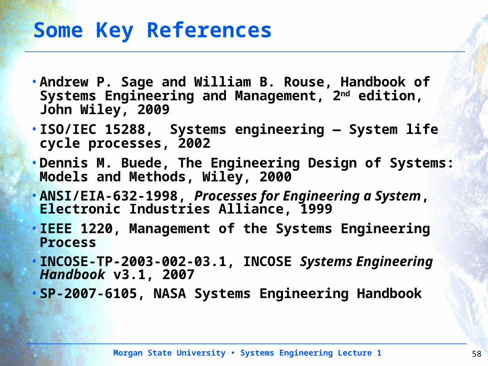
Some Key References
•Andrew P. Sage and William B. Rouse, Handbook of Systems Engineering and Management, 2nd edition, John Wiley, 2009
•ISO/IEC 15288, Systems engineering — System life cycle processes, 2002
•Dennis M. Buede, The Engineering Design of Systems: Models and Methods, Wiley, 2000
•ANSI/EIA-632-1998, Processes for Engineering a System, Electronic Industries Alliance, 1999
•IEEE 1220, Management of the Systems Engineering Process
•INCOSE-TP-2003-002-03.1, INCOSE Systems Engineering Handbook v3.1, 2007
•SP-2007-6105, NASA Systems Engineering Handbook
Morgan State University • Systems Engineering Lecture 1 59
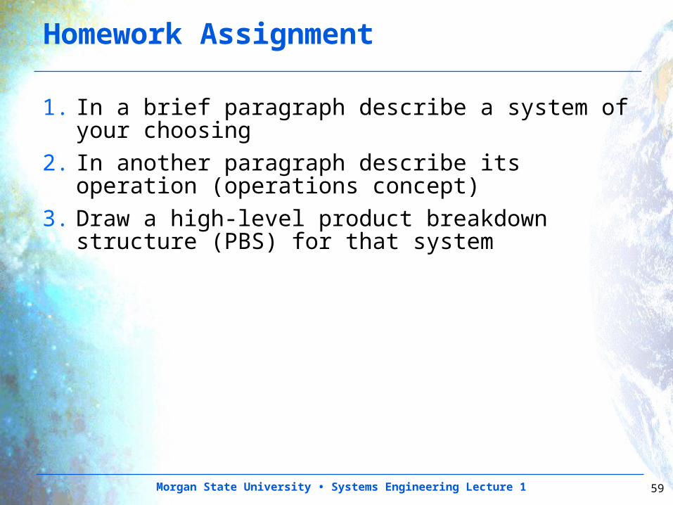
Homework Assignment
1. In a brief paragraph describe a system of your choosing
2. In another paragraph describe its operation (operations concept)
3. Draw a high-level product breakdown structure (PBS) for that system