Embed Size (px)
Citation preview
HDR 104
CHAPTER 5
RADIOGRAPHIC EQUIPMENT AND IMAGE RECORDING 1
PRINCIPLES OF RADIOGRAPHIC
PROCESSING
PREPARED BY:MR KAMARUL AMIN BIN ABDULLAH
SCHOOL OF MEDICAL IMAGINGFACULTY OF HEALTH SCIENCE
Slide 2 of 52
TOPIC
CHAPTER 5: Principle of Radiographic Processing
LEARNING OUTCOMES
At the end of the lesson, student should able to:-
Briefly explain the chemicals used and roles in radiographic processing.
The agents and roles in the developer and fixer.
Describe the 4 steps of processing
Describe the path of the film traveling through the processor
Slide 3 of 52
TOPIC
CHAPTER 5: Principle of Radiographic Processing
Purpose of PROCESSING
Change silver halide crystals from film emulsion (after exposure to x-ray or
light photons) to black metallic silver.
Latent image (invisible until processed) is developed into a visible image.
Improper or careless processing can cause poor diagnostic quality.

Slide 4 of 52
TOPIC
CHAPTER 5: Principle of Radiographic Processing
FOUR (4) Steps of PROCESSING
Developing – formation of the image, converts latent image into visible image
Fixing – stopping of development, permanent fixing of image on film, clear
the film of unexposed, undeveloped silver bromide crystals, promotes archival
quality
Washing – removal of residual fixer.
Drying – warm air blowing over film.
Slide 5 of 52
TOPIC
CHAPTER 5: Principle of Radiographic Processing
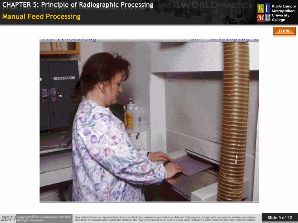
Manual Feed Processing

Slide 6 of 52
TOPIC
CHAPTER 5: Principle of Radiographic Processing
Hand Processing in the Early years
• Strong smell of chemicals
• Messy
• Time consuming
Slide 7 of 52
TOPIC
CHAPTER 5: Principle of Radiographic Processing
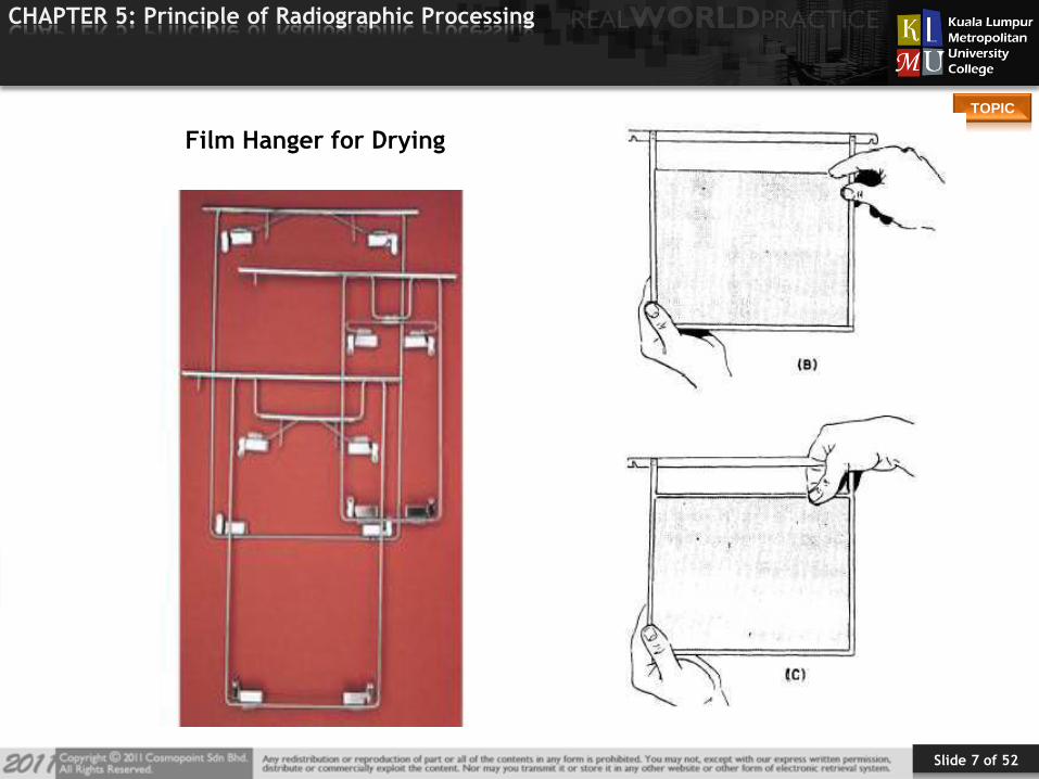
Film Hanger for Drying

Slide 8 of 52
TOPIC
CHAPTER 5: Principle of Radiographic Processing
1956 – first roller transport6 minute processing time

Slide 9 of 52
TOPIC
CHAPTER 5: Principle of Radiographic Processing
Processing Time
3 MINUTES 90 SECONDS
Slide 10 of 52
TOPIC
CHAPTER 5: Principle of Radiographic Processing
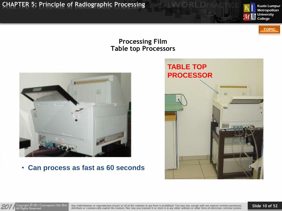
Processing FilmTable top Processors
• Can process as fast as 60 seconds
TABLE TOP
PROCESSOR
Slide 11 of 52
TOPIC
CHAPTER 5: Principle of Radiographic Processing
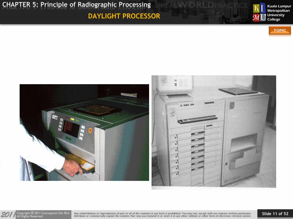
DAYLIGHT PROCESSOR
Slide 12 of 52
TOPIC
CHAPTER 5: Principle of Radiographic Processing
Daylight Processor
Enable film to be processed without need for darkroom
Special cassettes
Increase in department efficiency, no need for special darkroom staff
Disadvantages – cost, mechanical breakdowns
Slide 13 of 52
TOPIC
CHAPTER 5: Principle of Radiographic Processing
AUTOMATIC PROCESSING
1. TRANSPORTATION SYSTEM
2. DEVELOPER
3. FIXER
4. WASHER
5. DRYER
6. REPLENISHMENT SYSTEM
Slide 14 of 52
TOPIC
CHAPTER 5: Principle of Radiographic Processing
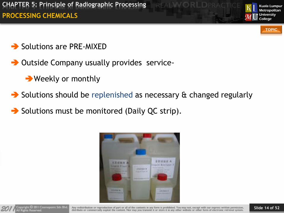
PROCESSING CHEMICALS
Solutions are PRE-MIXED
Outside Company usually provides service-
Weekly or monthly
Solutions should be replenished as necessary & changed regularly
Solutions must be monitored (Daily QC strip).
Slide 15 of 52
TOPIC
CHAPTER 5: Principle of Radiographic Processing
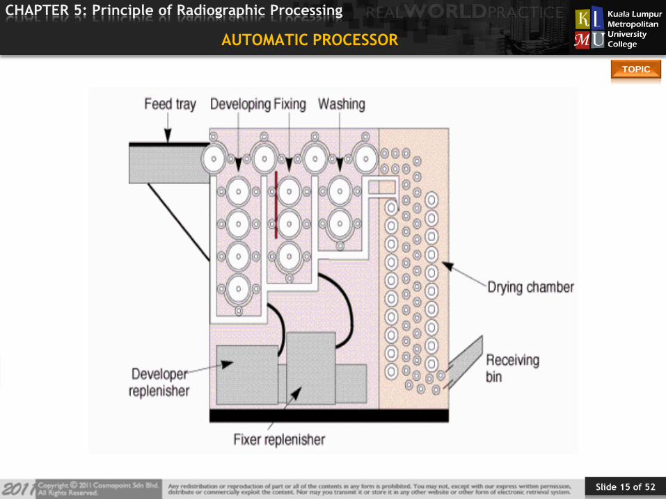
AUTOMATIC PROCESSOR
Slide 16 of 52
TOPIC
CHAPTER 5: Principle of Radiographic Processing
DEVELOPER
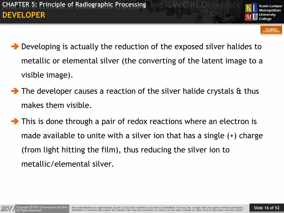
Developing is actually the reduction of the exposed silver halides to
metallic or elemental silver (the converting of the latent image to a
visible image).
The developer causes a reaction of the silver halide crystals & thus
makes them visible.
This is done through a pair of redox reactions where an electron is
made available to unite with a silver ion that has a single (+) charge
(from light hitting the film), thus reducing the silver ion to
metallic/elemental silver.
Slide 17 of 52
TOPIC
CHAPTER 5: Principle of Radiographic Processing
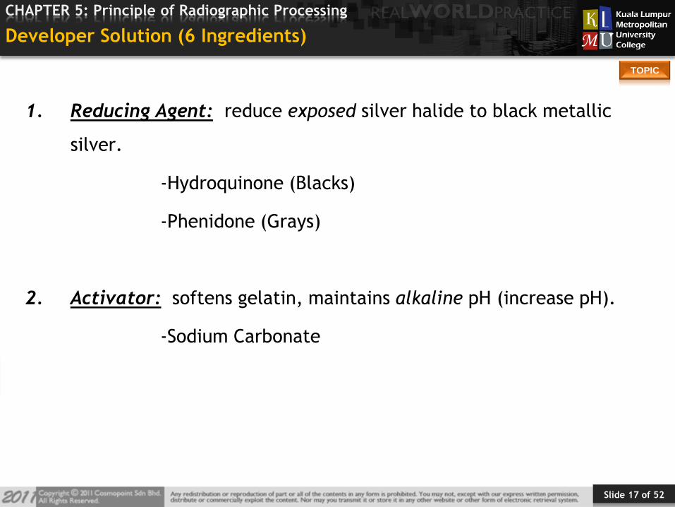
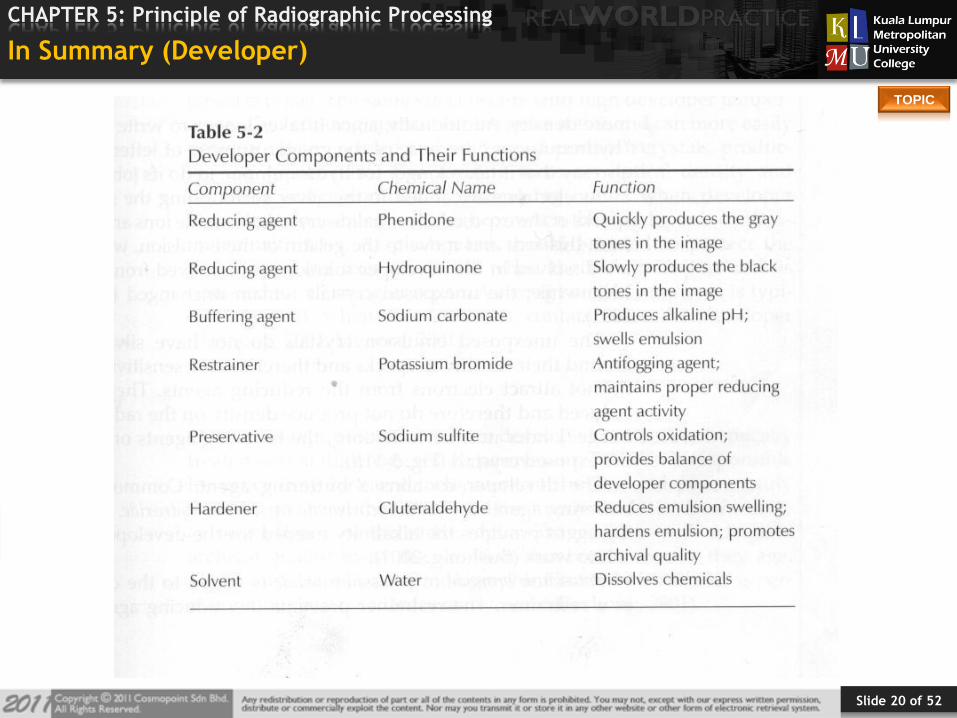
Developer Solution (6 Ingredients)
1. Reducing Agent: reduce exposed silver halide to black metallic
silver.
-Hydroquinone (Blacks)
-Phenidone (Grays)
2. Activator: softens gelatin, maintains alkaline pH (increase pH).
-Sodium Carbonate
Slide 18 of 52
TOPIC
CHAPTER 5: Principle of Radiographic Processing
Developer Solution
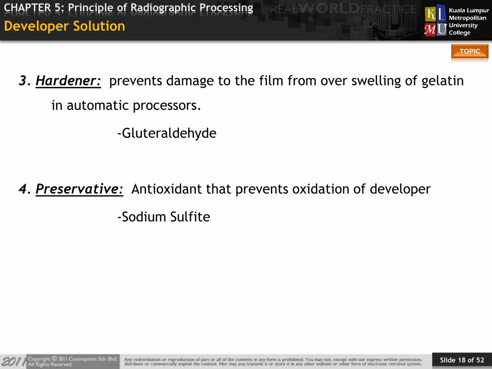
3. Hardener: prevents damage to the film from over swelling of gelatin
in automatic processors.
-Gluteraldehyde
4. Preservative: Antioxidant that prevents oxidation of developer
-Sodium Sulfite
Slide 19 of 52
TOPIC
CHAPTER 5: Principle of Radiographic Processing
Developer Solution
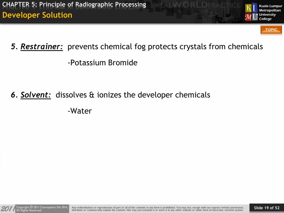
5. Restrainer: prevents chemical fog protects crystals from chemicals
-Potassium Bromide
6. Solvent: dissolves & ionizes the developer chemicals
-Water
Slide 20 of 52
TOPIC
CHAPTER 5: Principle of Radiographic Processing
In Summary (Developer)
Slide 21 of 52
TOPIC
CHAPTER 5: Principle of Radiographic Processing
Fixing
Once development is complete, the film must be treated so
that the image will not fade but will remain permanently.
Slide 22 of 52
TOPIC
CHAPTER 5: Principle of Radiographic Processing
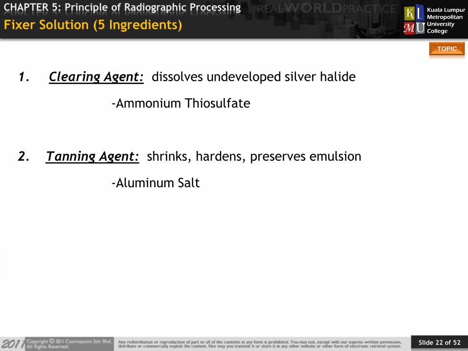
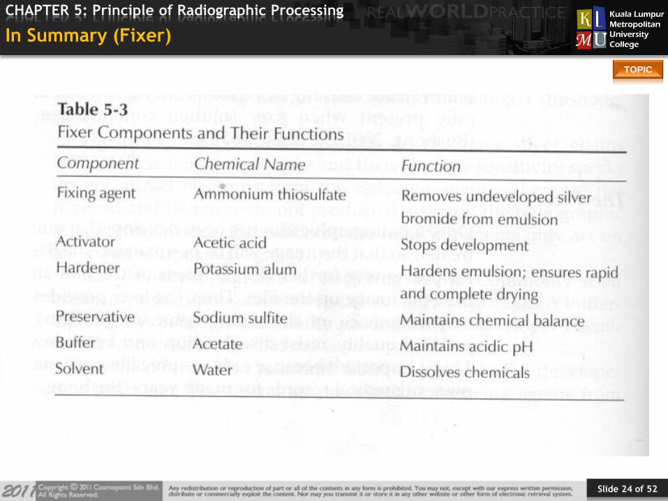
Fixer Solution (5 Ingredients)
1. Clearing Agent: dissolves undeveloped silver halide
-Ammonium Thiosulfate
2. Tanning Agent: shrinks, hardens, preserves emulsion
-Aluminum Salt
Slide 23 of 52
TOPIC
CHAPTER 5: Principle of Radiographic Processing
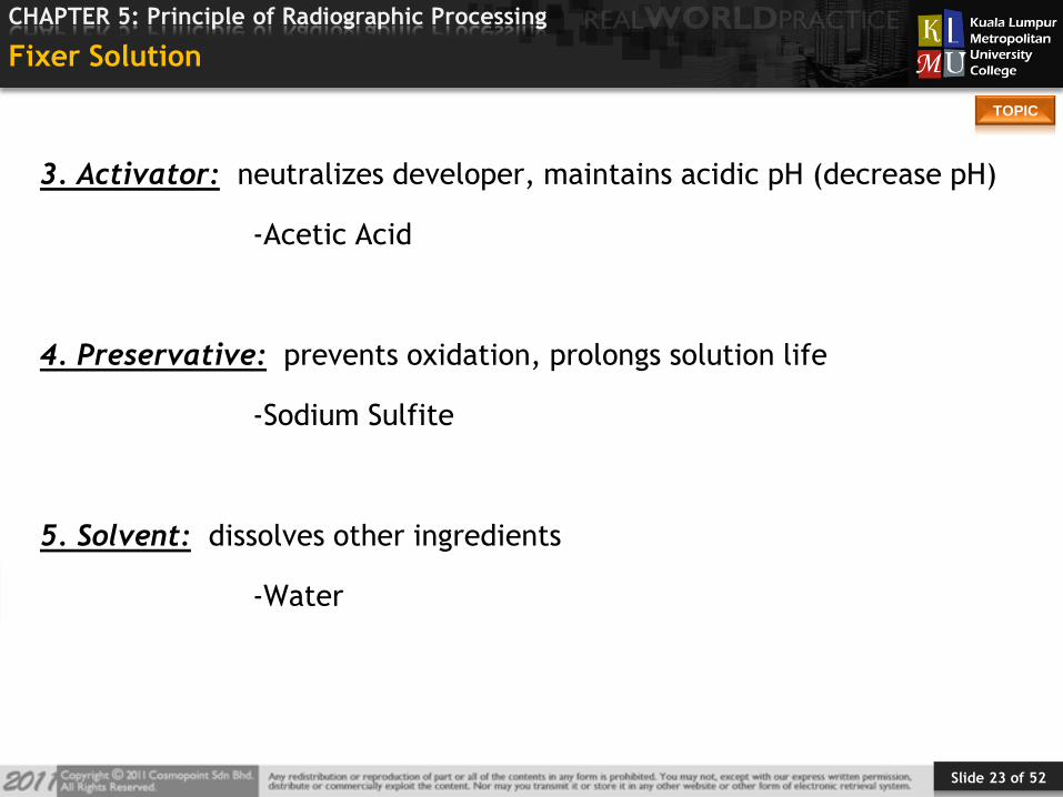
Fixer Solution
3. Activator: neutralizes developer, maintains acidic pH (decrease pH)
-Acetic Acid
4. Preservative: prevents oxidation, prolongs solution life
-Sodium Sulfite
5. Solvent: dissolves other ingredients
-Water
Slide 24 of 52
TOPIC
CHAPTER 5: Principle of Radiographic Processing
In Summary (Fixer)
Slide 25 of 52
TOPIC
CHAPTER 5: Principle of Radiographic Processing
Wash
Rid the film of residual chemicals
Residual chemicals on the film will discolor radiograph over time.
Cold water processors are less efficient in removing chemicals – Warm
water processors much better.
Agitation during wash process is essential
Slide 26 of 52
TOPIC
CHAPTER 5: Principle of Radiographic Processing
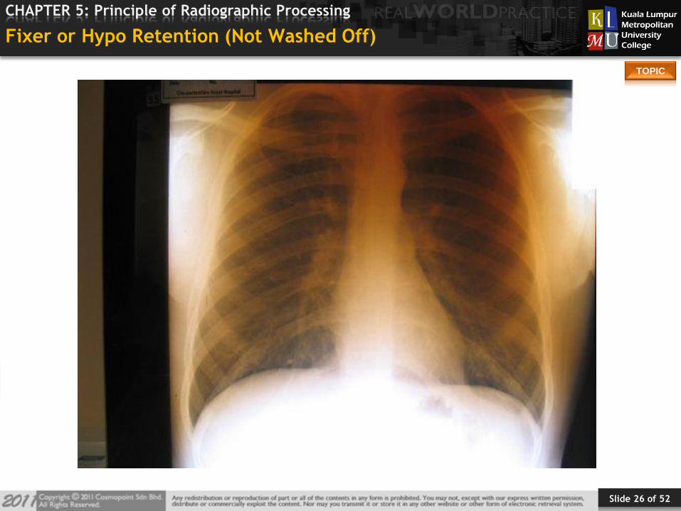
Fixer or Hypo Retention (Not Washed Off)
Slide 27 of 52
TOPIC
CHAPTER 5: Principle of Radiographic Processing
Dryer Systems
Dryer: Removes water from film by blowing warm, dry air
-Between 120 degrees & 130 degrees F.
Dries the film before its removal for viewing
If not dry, difficult to hang on viewing box
Consists of blower, ventilation ducts, vented dryer tubes & exhaust
system
Blower draws in air from room and passes it over heating coils
Heated air enters ventilation ducts & dryer tubes & then blows over
film
Moist warm air vented
Slide 28 of 52
TOPIC
CHAPTER 5: Principle of Radiographic Processing
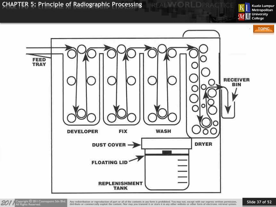
Transport System in Automatic Processors
Conveys the film through different solutions (sections) by a series of
rollers driven by gears, chains & sprockets.
Done at a prescribed speed – determines length of time the film is in
each solution
Slide 29 of 52
TOPIC
CHAPTER 5: Principle of Radiographic Processing
Transport System
Film fed on feed tray in darkroom
Entrance rollers grab film and draw it into developer
Entrance rollers separate slightly, film passes between rollers
activating microswitch controlling replenishment of chemicals
When film completely in developer tank bell ring or light flicks on –
safe to turn on light
Slide 30 of 52
TOPIC
CHAPTER 5: Principle of Radiographic Processing
Transport System Components
Feed Tray
Rollers (Different Assemblies):
1. Entrance
2. Deep Racks
3. Turnaround
4. Crossover
5. Squeegee
6. Dryer
Receiving Bin
Slide 31 of 52
TOPIC
CHAPTER 5: Principle of Radiographic Processing
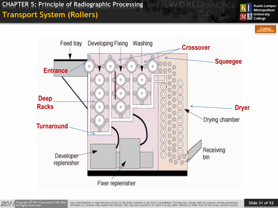
Transport System (Rollers)
Crossover
Squeegee
Dryer
Turnaround
Deep
Racks
Entrance

Slide 32 of 52
TOPIC
CHAPTER 5: Principle of Radiographic Processing
Feed Tray
Engages a micro switch to start the replenishment system.
Always feed the film evenly, using the side rails of the feed tray.
Alternate sides from film to film.
Short side of film against the side rail for proper replenishment.
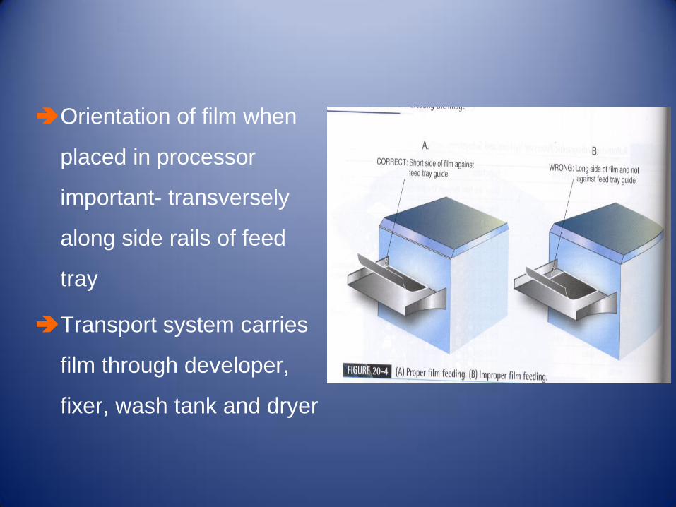
Orientation of film when
placed in processor
important- transversely
along side rails of feed
tray
Transport system carries
film through developer,
fixer, wash tank and dryer

Rollers
Transport rollers – front
and back positions in
racks, 1inch in diameter
Turnaround Assembly – 3
inch roller master roller
Planetary Rollers surround
master roller

Transport Racks
Support rollers and
turnaround
assemblies
Can be removed for
cleaning

Drive Motor
Electric motor & a
system of gears
chains, sprockets, bel
ts and pulleys provide
power & motion in
transport system
Slide 37 of 52
TOPIC
CHAPTER 5: Principle of Radiographic Processing
Slide 38 of 52
TOPIC
CHAPTER 5: Principle of Radiographic Processing
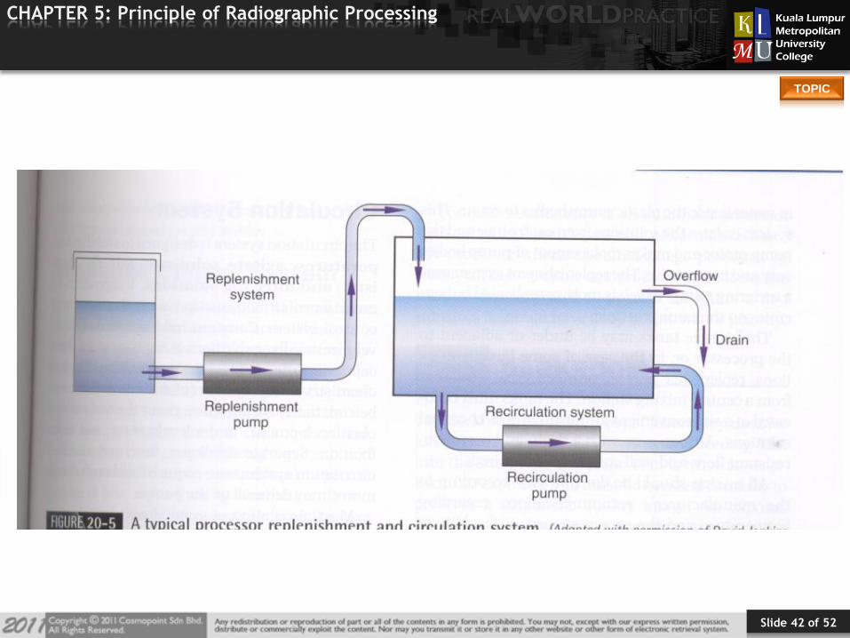
Recirculation System
Controlled by recirculation pumps that agitate solutions to
keep them mixed to maintain constant temperature
Circulation of water required to wash residual fixer (12
litres per minute)
Provides agitation necessary for uniform solution
concentration
Slide 39 of 52
TOPIC
CHAPTER 5: Principle of Radiographic Processing
Replenishment System
Main function: Keep solution tanks full and assure proper solution
concentration.
As film is introduced into processor, sensor initiates solution
replenishment
Right & wrong way to feed in film
-Feed in along short edge
Slide 40 of 52
TOPIC
CHAPTER 5: Principle of Radiographic Processing
Replenishment System
Fixer & developer levels drop as films processed
system replaces lost chemicals
Microswitch of entrance rollers starts replenishment pump – stops
when film exits entrance rollers
Placing films transversely stops excess waste of chemicals
Slide 41 of 52
TOPIC
CHAPTER 5: Principle of Radiographic Processing
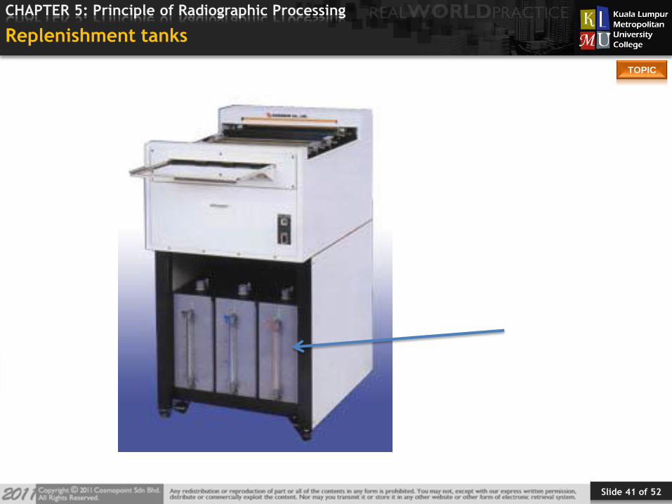
Replenishment tanks
Slide 42 of 52
TOPIC
CHAPTER 5: Principle of Radiographic Processing
Slide 43 of 52
TOPIC
CHAPTER 5: Principle of Radiographic Processing
Temperature Regulation
Main function: To control the temperature of each section of the
processor.
Developer – most important solution to regulate
Usually between 92 degrees and 95 degrees
Thermostatically controlled
Slide 44 of 52
TOPIC
CHAPTER 5: Principle of Radiographic Processing
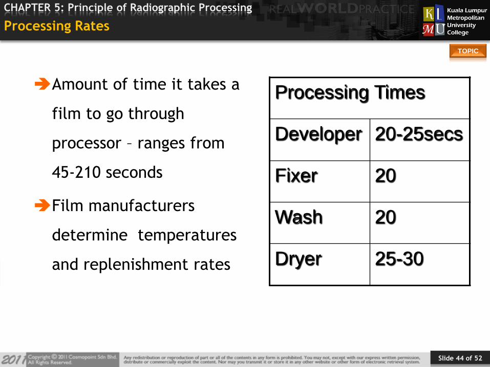
Processing Rates
Amount of time it takes a
film to go through
processor – ranges from
45-210 seconds
Film manufacturers
determine temperatures
and replenishment rates
Processing Times
Developer 20-25secs
Fixer 20
Wash 20
Dryer 25-30
Slide 45 of 52
TOPIC
CHAPTER 5: Principle of Radiographic Processing
Silver Recovery
About ½ of the film’s silver remains in the emulsion after exposure &
processing.
Other ½ (unexposed silver) is removed from the film during fixing
process.
Silver is toxic to public water supply – must have proper disposal.